US11324538B2 - Active bone plate - Google Patents
Active bone plateDownload PDFInfo
- Publication number
- US11324538B2 US11324538B2US17/086,757US202017086757AUS11324538B2US 11324538 B2US11324538 B2US 11324538B2US 202017086757 AUS202017086757 AUS 202017086757AUS 11324538 B2US11324538 B2US 11324538B2
- Authority
- US
- United States
- Prior art keywords
- plate
- anvils
- bone
- plate frame
- resiliency
- Prior art date
- Legal status (The legal status is an assumption and is not a legal conclusion. Google has not performed a legal analysis and makes no representation as to the accuracy of the status listed.)
- Active
Links
Images


Classifications
- A—HUMAN NECESSITIES
- A61—MEDICAL OR VETERINARY SCIENCE; HYGIENE
- A61B—DIAGNOSIS; SURGERY; IDENTIFICATION
- A61B17/00—Surgical instruments, devices or methods
- A61B17/56—Surgical instruments or methods for treatment of bones or joints; Devices specially adapted therefor
- A61B17/58—Surgical instruments or methods for treatment of bones or joints; Devices specially adapted therefor for osteosynthesis, e.g. bone plates, screws or setting implements
- A61B17/68—Internal fixation devices, including fasteners and spinal fixators, even if a part thereof projects from the skin
- A61B17/80—Cortical plates, i.e. bone plates; Instruments for holding or positioning cortical plates, or for compressing bones attached to cortical plates
- A61B17/8033—Cortical plates, i.e. bone plates; Instruments for holding or positioning cortical plates, or for compressing bones attached to cortical plates having indirect contact with screw heads, or having contact with screw heads maintained with the aid of additional components, e.g. nuts, wedges or head covers
- A61B17/8047—Cortical plates, i.e. bone plates; Instruments for holding or positioning cortical plates, or for compressing bones attached to cortical plates having indirect contact with screw heads, or having contact with screw heads maintained with the aid of additional components, e.g. nuts, wedges or head covers wherein the additional element surrounds the screw head in the plate hole
- A—HUMAN NECESSITIES
- A61—MEDICAL OR VETERINARY SCIENCE; HYGIENE
- A61B—DIAGNOSIS; SURGERY; IDENTIFICATION
- A61B17/00—Surgical instruments, devices or methods
- A61B17/56—Surgical instruments or methods for treatment of bones or joints; Devices specially adapted therefor
- A61B17/58—Surgical instruments or methods for treatment of bones or joints; Devices specially adapted therefor for osteosynthesis, e.g. bone plates, screws or setting implements
- A61B17/68—Internal fixation devices, including fasteners and spinal fixators, even if a part thereof projects from the skin
- A61B17/80—Cortical plates, i.e. bone plates; Instruments for holding or positioning cortical plates, or for compressing bones attached to cortical plates
- A61B17/8004—Cortical plates, i.e. bone plates; Instruments for holding or positioning cortical plates, or for compressing bones attached to cortical plates with means for distracting or compressing the bone or bones
- A61B17/8014—Cortical plates, i.e. bone plates; Instruments for holding or positioning cortical plates, or for compressing bones attached to cortical plates with means for distracting or compressing the bone or bones the extension or compression force being caused by interaction of the plate hole and the screws
- A—HUMAN NECESSITIES
- A61—MEDICAL OR VETERINARY SCIENCE; HYGIENE
- A61B—DIAGNOSIS; SURGERY; IDENTIFICATION
- A61B17/00—Surgical instruments, devices or methods
- A61B17/56—Surgical instruments or methods for treatment of bones or joints; Devices specially adapted therefor
- A61B17/58—Surgical instruments or methods for treatment of bones or joints; Devices specially adapted therefor for osteosynthesis, e.g. bone plates, screws or setting implements
- A61B17/68—Internal fixation devices, including fasteners and spinal fixators, even if a part thereof projects from the skin
- A61B17/80—Cortical plates, i.e. bone plates; Instruments for holding or positioning cortical plates, or for compressing bones attached to cortical plates
- A61B17/8052—Cortical plates, i.e. bone plates; Instruments for holding or positioning cortical plates, or for compressing bones attached to cortical plates immobilised relative to screws by interlocking form of the heads and plate holes, e.g. conical or threaded
- A61B17/8057—Cortical plates, i.e. bone plates; Instruments for holding or positioning cortical plates, or for compressing bones attached to cortical plates immobilised relative to screws by interlocking form of the heads and plate holes, e.g. conical or threaded the interlocking form comprising a thread
- A—HUMAN NECESSITIES
- A61—MEDICAL OR VETERINARY SCIENCE; HYGIENE
- A61B—DIAGNOSIS; SURGERY; IDENTIFICATION
- A61B17/00—Surgical instruments, devices or methods
- A61B17/56—Surgical instruments or methods for treatment of bones or joints; Devices specially adapted therefor
- A61B17/58—Surgical instruments or methods for treatment of bones or joints; Devices specially adapted therefor for osteosynthesis, e.g. bone plates, screws or setting implements
- A61B17/68—Internal fixation devices, including fasteners and spinal fixators, even if a part thereof projects from the skin
- A61B17/84—Fasteners therefor or fasteners being internal fixation devices
- A61B17/86—Pins or screws or threaded wires; nuts therefor
- A61B17/8625—Shanks, i.e. parts contacting bone tissue
- A61B17/863—Shanks, i.e. parts contacting bone tissue with thread interrupted or changing its form along shank, other than constant taper
- A—HUMAN NECESSITIES
- A61—MEDICAL OR VETERINARY SCIENCE; HYGIENE
- A61B—DIAGNOSIS; SURGERY; IDENTIFICATION
- A61B17/00—Surgical instruments, devices or methods
- A61B17/56—Surgical instruments or methods for treatment of bones or joints; Devices specially adapted therefor
- A61B17/58—Surgical instruments or methods for treatment of bones or joints; Devices specially adapted therefor for osteosynthesis, e.g. bone plates, screws or setting implements
- A61B17/68—Internal fixation devices, including fasteners and spinal fixators, even if a part thereof projects from the skin
- A61B2017/681—Alignment, compression, or distraction mechanisms
Definitions
- the present disclosurerelates to bone plates. Specifically, the present disclosure relates to active bone plates and methods of use thereof.
- Bone platesare used in a variety of surgical procedures, such as to treat fractures of bones in the body.
- an elongate bone plate with a plurality of fixation holes along its extentcan be used to affix the bone plate to multiple bone fragments of a fractured bone.
- the bone platebridges the gaps created between bone fragments to provide support for the fractured bone and aiding in the healing process.
- Example 1is a bone plate comprising: a plate frame having a first surface, the plate frame defining a first opening and a second opening along a longitudinal axis that extends from opposing ends of the plate frame; and a first anvil and a second anvil, the first and second anvils each comprising: a first plate having a first surface arranged to rest against the first surface of the plate frame when the bone plate is implanted, a second plate sized to pass into each of the first and second openings, and a body located in between the first and second plates, the body defining a through hole sized to receive a fastener, the body sized such that the plate frame is moveable along the longitudinal axis relative to the first and second anvils when the bone plate is implanted.
- Example 2the subject matter of Example 1 optionally includes wherein the first surface of the plate frame defines a recess sized to receive the first plate of each of the first and second anvils.
- Example 3the subject matter of any one or more of Examples 1-2 optionally include wherein the plate frame defines first and second locking pin holes and the first plate of each of the first and second anvils defines a complementary locking pin hole.
- Example 4the subject matter of any one or more of Examples 1-3 optionally include wherein the first anvil is manufactured from a metal and includes a polymer cladding.
- Example 5the subject matter of any one or more of Examples 1-4 optionally include wherein the plate frame includes first and second flexible tabs projecting into the first and second openings, respectively, and wherein the second plate of each of the first and second anvils includes first and second beveled flanges configured to engage the first and second flexible tabs, respectively.
- Example 6the subject matter of any one or more of Examples 1-5 optionally include wherein the through hole of the first anvil is unthreaded so as to receive a compression screw.
- Example 7the subject matter of any one or more of Examples 1-6 optionally include wherein the through hole of the second anvil is threaded so as to receive a locking screw.
- Example 8the subject matter of any one or more of Examples 1-7 optionally include wherein the second plate of the first and second anvils each protrudes below a second surface of the plate frame when implanted, the second surface of the plate frame located opposite the first surface of the plate frame.
- Example 9the subject matter of any one or more of Examples 1-8 optionally include wherein the first and second openings are rectangular.
- Example 10the subject matter of any one or more of Examples 1-9 optionally include wherein the first anvil includes a first gasket and the second anvil includes a second gasket.
- Example 11the subject matter of Example 10 optionally includes wherein the first gasket has a first resiliency and the second gasket has a second resiliency, the first resiliency being greater than the second resiliency.
- Example 12the subject matter of any one or more of Examples 10-11 optionally include wherein the first gasket has a first resiliency and the second gasket has a second resiliency, the first resiliency and the second resiliency being equal.
- Example 13is a bone plate system comprising: a plate frame having a first surface and a longitudinal axis extending between opposed first and second ends of the plate frame, the plate frame defining a plurality of openings; a plurality of fasteners; and a plurality of anvils, each of the plurality of anvils comprising: a first plate having a first surface arranged to rest against the first surface of the plate frame when the plate frame is implanted, a second plate sized to pass through at least one of the plurality of openings, and a body located in between the first plate and the second plate, the body defining a through hole sized to receive one of the plurality of fasteners, the body sized such that, when implanted, the body is moveable along the longitudinal axis of the plate frame.
- Example 14the subject matter of Example 13 optionally includes a plurality of locking pins, the plate frame defining a plurality of locking pin holes and the first plate of each of the plurality of anvils defining a complementary locking pin hole.
- Example 15the subject matter of any one or more of Examples 13-14 optionally include wherein the plate frame includes a plurality of flexible tabs, each of the plurality of flexible tabs projecting into a corresponding one of the plurality openings, and wherein the second plate of each of the plurality of anvils includes a beveled flange configured to engage one of the plurality of flexible tabs.
- Example 16the subject matter of any one or more of Examples 13-15 optionally include wherein the second plate of at least one of the plurality of anvils protrudes below a second surface of the plate frame when implanted, the second surface of the plate frame located opposite the first surface of the plate frame.
- Example 17the subject matter of any one or more of Examples 13-16 optionally include wherein a first subset of the plurality of anvils is a first size and a second subset of the plurality of anvils is a second size, the first and second sizes being different.
- Example 18the subject matter of any one or more of Examples 13-17 optionally include wherein each of the plurality of anvils includes a gasket.
- Example 19the subject matter of Example 18 optionally includes wherein the gasket of a first one of the plurality of anvils has a first resiliency and the gasket of a second one of the plurality of anvils has a second resiliency, the first resiliency being different than the second resiliency.
- Example 20the subject matter of any one or more of Examples 18-19 optionally include wherein the gasket of a first one of the plurality of anvils has a first resiliency and the gasket of a second one of the plurality of anvils has a second resiliency, the first resiliency and the second resiliency being equal.
- Example 21a bone plate or a bone plate system of any one or any combination of Examples 1-20 can optionally be configured such that all elements or options recited are available to use or select from.
- FIGS. 1A, 1B, and 1Cshow a bone plate system in accordance with at least one example of the present disclosure.
- FIGS. 2A, 2B, and 2Cshow a plate frame in accordance with at least one example of the present disclosure.
- FIGS. 3A, 3B, and 3Cshow an anvil and a gasket in accordance with at least one example of the present disclosure.
- FIGS. 4A and 4Bshow an anvil and a gasket in accordance with at least one example of the present disclosure.
- FIGS. 5A and 5Bshow an anvil and a gasket in accordance with at least one example of the present disclosure.
- FIGS. 6A and 6Bshow the insertion of an anvil into a plate frame in accordance with at least one example of the present disclosure.
- FIG. 7shows an anvil inserted into a plate frame in accordance with at least one example of the present disclosure.
- FIG. 8shows a method in accordance with at least one example of the present disclosure.
- a nailing approachcan promote secondary bone healing and can create a faster and stronger bone healing since there is a relative motion of diaphysis bone fragments that can stimulate the remodeling tissue.
- Traditional bone platesdo not allow for the relative motion of diaphysis bone.
- the bone plates and bone plate systems disclosed hereinallow for relative motion of diaphysis bone.
- the bone plates and bone plate systems disclosed hereinincorporate at least axial displacement between screws that are used to hold a plate frame in place and the plate frame.
- the bone plates, bone plate systems, and method of use thereof disclosed hereininclude a bone plate that includes a plate frame and a plurality of anvils.
- the plate framecan have a first surface for the anvils to rest against.
- the plate framecan also define a plurality of openings. Each of the plurality of openings can accept one of the plurality of anvils.
- Each of the plurality of anvilscan have a size that is smaller than the plurality of openings so as to pass through the openings.
- each of the anvilscan include a gasket that can fill any space between the anvils and the openings.
- the gasketcan be a resilient material that can allow for movement of the anvils relative to the plate frame.
- the gasketcan allow for a dynamic response to loading, such as, for example, allowing for dampening or a delayed response to moderate impacts such as high-speed loads and slow ramping loads.
- resilient materialscan include elastomers, silicones, and materials that can respond with a viscoelastic behavior to physiological loading conditions.
- the movement of the anvils relative to the plate framecan allow for bone fragments to move.
- the movement of bone fragmentswhich does not occur with traditional bone plates, can stimulate bone growth to promote faster healing.
- the bone plate systems disclosed hereincan allow for movement of anvils, and bone fragments in a predefined direction with compression of the bone fragments.
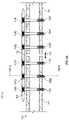
- FIGS. 1A, 1B, and 1Cillustrate a bone plate system 100 , in accordance with at least one example of this disclosure.
- Bone plate system 100can include a plate frame 102 , anvils 104 (labeled individually as anvil 104 A, 104 B, 104 C, 104 D, 104 E, and 104 F), and fasteners such as screws 106 (labeled individually as screw 106 A, 106 B, 106 C, 106 D, 106 E, and 106 F).
- screws 106can pass through anvils 104 and into a bone 108 .
- FIGS. 1Awhen implanted, screws 106 can pass through anvils 104 and into a bone 108 .
- screws 106can include a shaft 120 , a head 122 , and a self-tapping portion 124 .
- the self-tapping portioncan cut threads into bone 108 as shaft 120 passes into bone 108 .
- Head 122can rest in anvil 104 B.
- screws 106can be insertable in a polyaxial manner. For instance, screws 106 can each be inserted at an angle relative to a hole in anvils 104 through which they pass and at an angle relative to one another.
- Bone 108can have a bone gap 110 .
- Bone gap 110can be caused by a fracture or other trauma that caused bone 108 to be separated into a first bone fragment 112 and a second bone fragment 114 .
- Bone gap 110is shown exaggerated in FIG. 1A . Once bone plate system 100 is implanted first bone fragment 112 and second bone fragment 114 can be in contact with one another.
- first bone fragment 112 and second bone fragment 114can be moveable as indicated by arrow 116 .
- First bone fragment 112 and second bone fragment 114can be compressed against one another using bone plate system 100 .
- compression of first bone fragment 112 and second bone fragment 114 along with movement of first bone fragment 112 and second bone fragment 114can promote healing of the bone 108 .
- FIGS. 2A and 2Bshow a plate frame 200 , similar to plate frame 102 , in accordance was at least one example of the present disclosure.
- the plate frame 200can include a first surface 202 and a second surface 204 .
- the second surface 204can be located opposite the first surface 202 .
- a body 206 of the plate frame 200can define openings 208 (labeled individually as opening 208 A, 208 B, 208 C, and 208 D).
- the openings 208can pass through plate frame 200 .
- Plate frame 200can also define recesses 210 (labeled individually as recess 210 A, 210 B, 210 C, and 210 D).
- Recesses 210can allow a first plate of anvils disclosed herein to rest substantially flush with or beneath first surface 202 .
- a second plate of anvils disclosed hereincan pass through openings 208 and protrude below second surface 204 as disclosed herein with respect to at least FIG. 7 .
- FIGS. 2A and 2Bshow openings 208 arranged along a longitudinal axis 212 that extends from opposing first and second ends 213 and 215 of body 206 , openings 208 can be arranged staggered to longitudinal axis 212 as shown in FIG. 2C .
- FIGS. 2A and 2Bshow openings 208 arranged perpendicular to longitudinal axis 212 , openings 208 can be arranged at an angle relative to longitudinal axis 212 as shown in FIG. 2C .
- FIG. 2Cshows a plate frame 2250 that includes openings 208 and recesses 210 .
- Openings 208 and 210can be square or rectangular as shown in FIG. 2C .
- openings 208 and recesses 210can be a curved shape such as a circle or an oval.
- openings 208 and recesses 210can define any symmetrical or asymmetrical shape.
- Plate frame 200can include a combination of square and rectangular openings 208 and recesses 210 .
- An openingdoes not have to have a recess.
- opening 208 Acan have recess 210 A while opening 208 B does not have to have recess 210 B. While FIGS.
- openings 208may be circular and recesses 210 may be square.
- longitudinal axis 212When implanted, longitudinal axis 212 can be arranged parallel to arrow 116 ( FIG. 1A ). Orienting longitudinal axis 212 parallel to arrow 116 can allow for movement of first bone fragment 112 and second bone fragment 114 in a predefined direction. Stated another way, anvils 104 can be fixed to bone 108 via screws 106 and move relative to plate frame 102 . The movement of anvils 104 can be constrained along longitudinal axis 212 as disclosed herein.
- plate frame 102 and anvils 104can constrain movement of first bone fragment 112 and second bone fragment 114 along longitudinal axis 212 while also preventing movement of first bone fragment 112 and second bone fragment 114 in a direction perpendicular to longitudinal axis 212 .
- the constriction of movementcan allow first bone fragment 112 and second bone fragment 114 to be preloaded in contact with one another while preventing lateral movement that can cause additional damage to bone 108 .
- first bone fragment 112 and second bone fragment 114can be prevented from grinding against one another.
- Plate frame 200can be manufactured from a metal, polymer, ceramic, or any combination thereof.
- plate frame 200can be machined, cast, etc. from a metal.
- Plate frame 200can be injection molded from a polymer.
- Plate frame 200can be machined from a metal and then coated with a polymer cladding via an overmolding process.
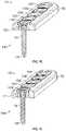
- FIGS. 3A, 3B, and 3Cshow an anvil 300 and a gasket 302 in accordance with at least one example of the present disclosure.
- Anvil 300can include a first plate 304 , a second plate 306 , and a body 308 located in between first plate 304 and second plate 306 .
- First plate 304 and second plate 306can be the same size or different sizes.
- first plate 304can extend past an exterior surface 310 of gasket 302 .
- first plate 304can allow a portion of first plate 304 to rest on a surface of a plate frame, such as plate frame 102 or plate frame 200 , while allowing body 308 and second plate 306 to rest in an opening, such as any one of openings 208 .
- First plate 304can also define a locking hole 312 . As disclosed herein, locking hole 312 can be used to lock anvil 300 to a plate frame while implanting a bone plate.
- Body 308can define a through hole 314 .
- Through hole 314can receive a fastener, such as one of screws 106 .
- through hole 314can allow for compression screws and locking screws to pass through anvil 300 to secure anvil 300 to a bone or bone fragment.
- through hole 314can include threads 316 to engage a locking screw to secure anvil 300 to a bone or bone fragment.
- Anvil 300can be manufactured from a metal, polymer, ceramic, or any combination thereof.
- anvil 300can be machined, cast, etc. from a metal.
- Anvil 300can be injection molded from a polymer.
- Anvil 300can be machined from a metal and then coated with a polymer or ceramic cladding.
- Gasket 302can be manufactured from a polymer or other flexible material. As shown in FIG. 3B , side portions 318 can be thinner than end portions 320 and define a through hole 322 . The thin and flexible nature of side portions 318 can allow gasket 302 to stretch and be slid over either first plate 304 or second plate 306 . Once clear of first plate 304 or second plate 306 , gasket 302 can encircle body 308 and rest in between first plate 304 and second plate 306 . Side portions 318 can rest flush with sidewalls 324 and 326 of first plate 304 and second plate 306 . Sidewalls 324 and 326 can protrude past exterior surface 310 of gasket 302 .
- FIGS. 4A and 4Bshow an anvil 400 and a gasket 402 in accordance with at least one example of the present disclosure.
- Anvil 400can include a first plate 404 , a second plate 406 , and a body 408 located in between first plate 404 and second plate 406 .
- First plate 404 and second plate 406can be the same size or different sizes as described above with respect to FIGS. 3A, 3B , and 3 C.
- the larger size of first plate 404can allow a portion of first plate 404 to rest on a surface of a plate frame, such as plate frame 102 or plate frame 200 , while allowing body 408 and second plate 406 to rest in an opening, such as any one of openings 208 .
- Body 408can define a through hole 414 .
- Through hole 414can receive a fastener, such as one of screws 106 .
- through hole 414can allow for compression screws and locking screws to pass through anvil 400 to secure anvil 400 to a bone or bone fragment.
- through hole 414can include threads 416 to engage a locking screw to secure anvil 400 to a bone or bone fragment.
- Anvil 400can be manufactured from a metal, polymer, ceramic, or any combination thereof.
- anvil 400can be machined, cast, etc. from a metal.
- Anvil 400can be injection molded from a polymer.
- anvil 400can include a cladding 430 .
- Cladding 430can be a polymer, metal, ceramic, or any combination thereof. Consistent with embodiments disclosed herein, cladding 430 can be a different material from a plate frame.
- cladding 430can be a polymer that is overmolded onto a metal anvil.
- the polymer cladding 430can include a lubricated polymer or other wear resistant material.
- cladding 430can eliminate metal on metal contact, which can cause wear and damage the bone plate.
- cladding 430can be a polyether ether ketone (PEEK) applied to bearing surfaces to allow anvil 400 to slide against surfaces of the plate frame.
- PEEKpolyether ether ketone
- Gasket 402can be manufactured from a polymer or other flexible material. As disclosed above with respect to FIG. 3B , side portion 418 can be thinner than end portions 420 and define a through hole as described herein. The thin and flexible nature of side portions 418 can allow gasket 402 to stretch and be slid over either first plate 404 or second plate 406 . Once clear of first plate 404 or second plate 406 , gasket 402 can encircle body 408 and rest in between first plate 404 and second plate 406 . Side portions 418 can rest flush with sidewalls 424 and 426 of first plate 404 and second plate 406 . Sidewalls 424 and 426 can protrude past exterior surface 410 of gasket 402 .
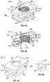
- FIGS. 5A and 5Bshow an anvil 500 and gaskets 502 in accordance with at least one example of the present disclosure.
- Anvil 500can include a first plate 504 , a second plate 506 , and a body 508 located in between first plate 504 and second plate 506 .
- First plate 504 and second plate 506can be the same size or different sizes as described above with respect to FIGS. 3A, 3B , and 3 C.
- the larger size of first plate 504can allow a portion of first plate 504 to rest on a surface of a plate frame, such as plate frame 102 or plate frame 200 , while allowing body 508 and second plate 506 to rest in an opening, such as any one of openings 208 .
- Body 508can define a through hole 514 .
- Through hole 514can receive a fastener, such as one of screws 106 .
- through hole 514can allow for compression screws and locking screws to pass through anvil 400 to secure anvil 400 to a bone or bone fragment.
- through hole 514can include a smooth surface 532 to allow a compression screw to engage anvil 500 .
- a non-threaded hole, such as through hole 514that includes a PEEK cladding (or anvil 500 is made from PEEK) can allow for a threaded head screw to be installed in a custom orientation. For example, the threads on the head of the screw can cut their own threads into the PEEK as the surgeon drives the screw into bone.
- Anvil 500can be manufactured from a metal, polymer, ceramic, or any combination thereof.
- anvil 500can be machined, cast, etc. from a metal.
- Anvil 500can be injection molded from a polymer.
- Anvil 500can include a cladding as described above with respect to FIGS. 4A and 4B .
- Making anvil 500 from a polymercan include making anvil 500 from a lubricated polymer or other wear resistant material. As such, movement of anvil 500 against a metal plate frame can minimize damage to anvil 500 and the plate frame.
- the plate framecan be made of a polymer and anvil 500 can be made of a metal.
- Gaskets 502can be manufactured from a polymer or other flexible material. As shown in FIG. 5B , gaskets 502 can have a flat face 534 and a curved portion 536 . Flat face 534 can include a mastic or other adhesive that can allow gaskets 502 to bond or otherwise adhere to body 508 . Gaskets 502 can be made of the same material or different materials. For example, one of gaskets 502 can be made of a first material and the other gasket 502 can be made of a second material. The first material can have a first resiliency and the second material can have a second resiliency. The first resiliency and the second resiliency can be the same or different.
- gaskets 502need not be present in every embodiment.
- a gasket 502can be attached to body 508 opposite the bone gap.
- gasket 502can apply a force to the plate frame that pushes anvil 500 towards to bone gap.
- gasket 502can be attached to body 508 on the same side as the bone gap.
- gasket 502can act as a shock absorber to minimize impact forces that may be created if bone fragments are permitted to hit one another under loading. For instance, when a patient walks, gasket 502 can act as a shock absorber to minimize impact forces generated in femur fragments generated when the patient's foot hits the floor.
- the thickness of gaskets 502can be such that friction is able to secure gaskets 502 in between first plate 504 and second plate 506 .
- the thickness of gaskets 502may be 5.5 mm.
- the radius, R, of gaskets 502can vary.
- one of gaskets 502can have a radius or R 1 and the other gasket 502 can have a radius of R 2 .
- the surgeoncan select gaskets 502 to adjust the travel of anvil 500 within an opening of a plate frame. For instance, to increase the distance anvil 500 can move within an opening of a plate frame, gaskets 502 with a smaller radius can be selected. To decrease the distance anvil 500 can move within an opening of a plate frame, gaskets 502 with a larger radius can be selected.
- FIGS. 6A and 6Bshow the insertion of an anvil 600 into a plate frame 650 in accordance with at least one example of the present disclosure.
- Anvil 600can include a gasket 602 , a first plate 604 , a second plate 606 , and a body 608 located in between first plate 604 and second plate 606 .
- Second plate 606can include a beveled flange 658 .
- a portion 662 of first plate 604can rest against first surface 612 .
- beveled flange 658can contact flexible tab 652 .
- the contactcan cause flexible tab 652 to flex such that beveled flange 658 and second plate 606 pass flexible tab 652 .
- flexible tab 652can be located in between first plate 604 and second plate 606 to retain anvil 600 in opening 660 as shown in FIG. 6B .
- Flexible tab 652can rest against gasket 602 or there can be space in between flexible tab 652 and gasket 602 .
- Plate frame 650can define a locking pin hole 654 and a recess 656
- Anvil 600can define a complementary locking pin hole 616 .
- a locking pin 664can be inserted into locking holes 616 and 654 . Insertion of locking pin 664 can restrict movement of anvil 600 within plate frame 650 .
- the restriction of movement of anvil 600can allow the surgeon to secure the anvil 600 to bone without anvil 600 moving. Having anvil 600 temporarily fixed to plate frame 650 can allow the surgeon to grip plate frame 650 instead of anvil 600 , thereby decreasing the risk of slippage and possible injury to the patient and surgeon do to movement of anvil 600 and plate frame 650 while being attached to bone.
- locking pin 664can be removed to allow anvil 600 to move relative to plate frame 650 ,
- FIG. 7shows an anvil 700 inserted into a plate frame 750 in accordance with at least one example of the present disclosure.
- Anvil 700can include a gasket 702 , a first plate 704 , a second plate 706 , and a body 708 .
- second plate 706can include a first flange 770 and a second flange 772 .
- First flange 770can have a length, L 1
- second flange 772can have a length L 2 .
- L 2can be less than L 1 .
- Second flange 772can include a curved surface 774 .
- gasket 702can compressing against a first portion 776 of plate frame 750 and body 708 as curved surface 774 contacts and presses against a second portion 778 of plate frame 750 . Upon clearing second portion 778 , gasket 702 may decompress and press second flange 772 underneath second portion 778 to secure anvil 700 to plate frame 750 .
- a bottom surface 760 of anvil 700can protrude past a bottom surface 762 of plate frame 750 . Having bottom surface 760 extend past bottom surface 762 can allow anvil 700 to be fixed to bone without having plate frame 750 also contact bone. Thus, by having bottom surface 760 extend past bottom surface 762 , anvil 700 and bone attached to anvil 700 can move without causing plate frame 750 to rub against bone. Minimizing contact between plate frame 750 and bone can reduce a risk of further damage to bone that can be cause by plate frame 750 rubbing against bone or bone fragments as they move.
- gasket 702can extend and cover portions of first plate 704 and second plate 706 . As a result, gasket 702 can act as a cladding, such as cladding 430 described above with respect to FIGS. 4A and 4B .
- FIG. 8shows a method 800 in accordance with at least one example of the present disclosure.
- Method 800can begin by providing or obtaining a bone plate system ( 802 ).
- Providing or obtaining a bone plate systemcan include providing or obtaining plate frames, anvils, fasteners, gaskets, etc. described herein,
- Providing or obtaining a bone plate systemcan include providing or obtaining anvils that include gaskets preinstalled or gaskets that are separate from the anvils. As such, the surgeon can select the gaskets and anvils as needed.
- the fastenerscan include locking screws and compression screws.
- Multiple plate framescan be provided or obtained and the plate frames can include differing numbers of openings, different arrangement of the openings, etc.
- the surgeon or other medical staffcan press anvils into openings of plate frame(s) so that a plate of each of the anvils rests against a first surface of the plate frame(s) ( 804 ).
- the anvilscan be pressed into the plate frame(s) as disclosed herein. Pressing the anvils into the openings can include pressing the anvils such that a bottom surface of the anvils protrudes below a bottom surface of the plate frame(s) as disclosed herein. Pressing the anvils into the plate frame(s) can include pressing a first plate of the anvils into recesses in the plate frame(s) as disclosed herein.
- locking pinscan be inserted into locking pin holes in the anvils and plate frame(s) ( 806 ). As disclosed herein, inserting the locking pins can immobilize the anvils within the openings. Immobilizing the anvils can reduce the risk of injury to the surgeon, patient, and other medical staff by increasing the surface area in which the surgeon and medical staff can grip the plate frame(s).
- fastenerscan be passed through each of the anvils to secure the plate frame(s) to the bone ( 808 ).
- the surgeoncan drill holes into the bone and screw locking and compression screws through the anvils and into the drilled holes in the bone.
- the locking pincan be removed from the locking pin holes.
- the anvilscan be freed to move relative to the plate frame(s). For example, once the locking pins are removed the anvils can translate along a longitudinal axis of the plate frame(s).
- the terms “a” or “an”are used, as is common in patent documents, to include one or more than one, independent of any other instances or usages of “at least one” or “one or more.”
- the term “or”is used to refer to a nonexclusive or, such that “A or B” includes “A but not B,” “B but not A,” and “A and B,” unless otherwise indicated.
Landscapes
- Health & Medical Sciences (AREA)
- Orthopedic Medicine & Surgery (AREA)
- Surgery (AREA)
- Life Sciences & Earth Sciences (AREA)
- Heart & Thoracic Surgery (AREA)
- Nuclear Medicine, Radiotherapy & Molecular Imaging (AREA)
- Engineering & Computer Science (AREA)
- Biomedical Technology (AREA)
- Neurology (AREA)
- Medical Informatics (AREA)
- Molecular Biology (AREA)
- Animal Behavior & Ethology (AREA)
- General Health & Medical Sciences (AREA)
- Public Health (AREA)
- Veterinary Medicine (AREA)
- Surgical Instruments (AREA)
Abstract
Description
Claims (20)
Priority Applications (1)
| Application Number | Priority Date | Filing Date | Title |
|---|---|---|---|
| US17/086,757US11324538B2 (en) | 2019-12-04 | 2020-11-02 | Active bone plate |
Applications Claiming Priority (2)
| Application Number | Priority Date | Filing Date | Title |
|---|---|---|---|
| US201962943321P | 2019-12-04 | 2019-12-04 | |
| US17/086,757US11324538B2 (en) | 2019-12-04 | 2020-11-02 | Active bone plate |
Publications (2)
| Publication Number | Publication Date |
|---|---|
| US20210169536A1 US20210169536A1 (en) | 2021-06-10 |
| US11324538B2true US11324538B2 (en) | 2022-05-10 |
Family
ID=76209292
Family Applications (1)
| Application Number | Title | Priority Date | Filing Date |
|---|---|---|---|
| US17/086,757ActiveUS11324538B2 (en) | 2019-12-04 | 2020-11-02 | Active bone plate |
Country Status (1)
| Country | Link |
|---|---|
| US (1) | US11324538B2 (en) |
Families Citing this family (1)
| Publication number | Priority date | Publication date | Assignee | Title |
|---|---|---|---|---|
| US8790379B2 (en) | 2010-06-23 | 2014-07-29 | Zimmer, Inc. | Flexible plate fixation of bone fractures |
Citations (127)
| Publication number | Priority date | Publication date | Assignee | Title |
|---|---|---|---|---|
| FR742618A (en) | 1933-03-10 | |||
| US2406832A (en) | 1945-03-05 | 1946-09-03 | Mervyn G Hardinge | Fracture plate |
| US2580821A (en) | 1950-10-21 | 1952-01-01 | Nicola Toufick | Spring impactor bone plate |
| US3807394A (en) | 1971-08-19 | 1974-04-30 | Nat Res Dev | Fracture fixing device |
| US4029091A (en) | 1974-08-12 | 1977-06-14 | Von Bezold Gotz Dietrich | Osteosynthesis |
| US4338296A (en) | 1979-10-16 | 1982-07-06 | Smithkline-Rit | Influenza virus and process of producing a vaccine therefrom |
| US4361153A (en) | 1980-05-27 | 1982-11-30 | Cordis Corporation | Implant telemetry system |
| US4743260A (en) | 1985-06-10 | 1988-05-10 | Burton Charles V | Method for a flexible stabilization system for a vertebral column |
| FR2634368A1 (en) | 1988-07-20 | 1990-01-26 | Massaad Raymond | Functional fixation device for osteosynthesis using a slide plate |
| US4905679A (en) | 1988-02-22 | 1990-03-06 | M P Operation, Inc. | Bone fracture reduction device and method of internal fixation of bone fractures |
| US4943292A (en) | 1989-11-08 | 1990-07-24 | National Research Council Of Canada | Plate for broken bone fixation |
| US5306310A (en) | 1991-08-27 | 1994-04-26 | Man Ceramics Gmbh | Vertebral prosthesis |
| EP0615728A2 (en) | 1993-02-16 | 1994-09-21 | MIKHAIL, Michael W.E. | Orthopaedic reconstruction plate |
| US5423816A (en) | 1993-07-29 | 1995-06-13 | Lin; Chih I. | Intervertebral locking device |
| US5468242A (en) | 1993-11-19 | 1995-11-21 | Leibinger Gmbh | Form-fitting mesh implant |
| US5578036A (en) | 1993-12-06 | 1996-11-26 | Stone; Kevin T. | Method and apparatus for fixation of bone during surgical procedures |
| US5578034A (en) | 1995-06-07 | 1996-11-26 | Danek Medical, Inc. | Apparatus for preventing screw backout in a bone plate fixation system |
| US5681311A (en) | 1994-09-15 | 1997-10-28 | Smith & Nephew, Inc. | Osteosynthesis apparatus |
| US5709686A (en) | 1995-03-27 | 1998-01-20 | Synthes (U.S.A.) | Bone plate |
| US5741258A (en) | 1993-01-25 | 1998-04-21 | Synthes (U.S.A.) | Lock washer for bone plate osteosynthesis |
| US5743913A (en) | 1997-04-02 | 1998-04-28 | Wellisz; Tadeusz Z. | Readily expansible bone fixation plate |
| US5984925A (en) | 1997-07-30 | 1999-11-16 | Cross Medical Products, Inc. | Longitudinally adjustable bone plates and method for use thereof |
| US6093188A (en) | 1997-11-10 | 2000-07-25 | Murray; William M. | Adjustable bone fixation plate |
| US6206882B1 (en) | 1999-03-30 | 2001-03-27 | Surgical Dynamics Inc. | Plating system for the spine |
| US6340632B1 (en) | 1999-06-04 | 2002-01-22 | Hitachi, Ltd. | Method of manufacturing a semiconductor device |
| US20020150671A1 (en) | 2001-02-09 | 2002-10-17 | Edouard Koulik | Methods for modifying surfaces of articles |
| US6540746B1 (en) | 1999-09-30 | 2003-04-01 | Sulzer Orthopedics Ltd. | Bone plate for splinting a fracture at a bone with a plurality of bone screws |
| US6663632B1 (en) | 1998-05-19 | 2003-12-16 | Synthes (U.S.A.) | Osteosynthetic implant with an embedded hinge joint |
| US20040006343A1 (en) | 2000-05-25 | 2004-01-08 | Sevrain Lionel C. | Auxiliary vertebrae connecting device |
| US20040019353A1 (en) | 2002-02-01 | 2004-01-29 | Freid James M. | Spinal plate system for stabilizing a portion of a spine |
| US20040097937A1 (en) | 2002-11-19 | 2004-05-20 | Sandi Pike | Orthopedic bone plate |
| US6755832B2 (en) | 2001-04-03 | 2004-06-29 | Inion Ltd. | Bone plate implant |
| US20040193155A1 (en) | 2003-03-27 | 2004-09-30 | Hand Innovations, Inc. | Fracture fixation plate with particular plate hole and fastener engagement and methods of using the same |
| JP2005507953A (en) | 2001-03-08 | 2005-03-24 | ザ・トラスティーズ・オブ・ザ・ユニバーシティ・オブ・ペンシルベニア | Superficially amphiphilic polymers as anti-infective agents |
| US20050090825A1 (en) | 2002-02-15 | 2005-04-28 | Medartis Ag | Bone plate |
| US20050096657A1 (en) | 2002-02-26 | 2005-05-05 | Alex Autericque | Osteosynthesis or arthrodesis material comprising a bony plate |
| US20050116930A1 (en) | 2003-11-06 | 2005-06-02 | Universal Electronics Inc. | Remote control having a display with multi-function EL segments |
| WO2005065557A1 (en) | 2004-01-08 | 2005-07-21 | David Mark Allison | Bone fixing device |
| US20050196421A1 (en) | 2003-11-20 | 2005-09-08 | Angiotech International Ag | Polymer compositions and methods for their use |
| US20050216008A1 (en) | 2004-03-24 | 2005-09-29 | Zwirnmann Ralph F | Bone fixation implants |
| US20050273105A1 (en) | 2002-12-31 | 2005-12-08 | Depuy Spine, Inc. | Bone plate and screw system allowing bi-directional assembly |
| US20050288668A1 (en) | 2002-06-24 | 2005-12-29 | Bernhard Brinkhaus | Spinal column support system |
| US6986771B2 (en) | 2003-05-23 | 2006-01-17 | Globus Medical, Inc. | Spine stabilization system |
| US20060058796A1 (en) | 2004-09-14 | 2006-03-16 | Hartdegen Vernon R | Compression brace |
| US7048739B2 (en) | 2002-12-31 | 2006-05-23 | Depuy Spine, Inc. | Bone plate and resilient screw system allowing bi-directional assembly |
| US20060116682A1 (en) | 2004-11-18 | 2006-06-01 | Longo Marc N | Surgical implant and methods of making and using the same |
| US20060155282A1 (en) | 2003-02-28 | 2006-07-13 | Silvana Vese | Osteosynthesis plate |
| US20060195099A1 (en) | 2005-02-15 | 2006-08-31 | Apex Abc, Llc | Bone screw for positive locking but flexible engagement to a bone |
| US20060241612A1 (en) | 2005-04-12 | 2006-10-26 | Robert J. Medoff | Bearing plate for use in fracture fixation having a spherical bearing hole with yielding expandability |
| US20060247639A1 (en) | 2005-04-29 | 2006-11-02 | Sdgi Holdings, Inc. | Apparatus for retaining a bone anchor in a bone plate and method for use thereof |
| US20060247638A1 (en) | 2005-04-29 | 2006-11-02 | Sdgi Holdings, Inc. | Composite spinal fixation systems |
| US20060264949A1 (en) | 2003-11-18 | 2006-11-23 | Georges Kohut | Osteosynthesis plate set |
| WO2007009124A2 (en) | 2005-07-13 | 2007-01-18 | Acumed Llc | Bone plates with movable locking elements |
| US7189237B2 (en) | 2002-11-19 | 2007-03-13 | Acumed Llc | Deformable bone plates |
| WO2007056874A1 (en) | 2005-11-16 | 2007-05-24 | Synthes Gmbh | A through hole for bone fixation device |
| US20070118127A1 (en) | 2005-11-22 | 2007-05-24 | Depuy Spine, Inc. | Implant fixation methods and apparatus |
| US20070213729A1 (en) | 2006-03-08 | 2007-09-13 | Sdgi Holdings, Inc. | Flexible bone plates and methods for dynamic spinal stabilization |
| US7276070B2 (en) | 2003-06-11 | 2007-10-02 | Mueckter Helmut | Osteosynthesis plate or comparable implant plus ball socket |
| CN101060815A (en) | 2004-06-07 | 2007-10-24 | 芯赛斯公司 | Orthopaedic implant with sensors |
| US20080027439A1 (en) | 2006-07-31 | 2008-01-31 | Sasing Jude L | Cervical plate system having an insertable rotating element |
| US7341591B2 (en) | 2003-01-30 | 2008-03-11 | Depuy Spine, Inc. | Anterior buttress staple |
| US20080083613A1 (en) | 2006-10-06 | 2008-04-10 | Nelson Oi | Port structures for non-rigid bone plates |
| US20080097445A1 (en) | 2006-10-23 | 2008-04-24 | Weinstein Robert B | Bone fixation system |
| US7377921B2 (en) | 2001-12-07 | 2008-05-27 | Synthes (U.S.A.) | Damping element and device for stabilization of adjacent vertebral bodies |
| EP1926445A1 (en) | 2005-09-23 | 2008-06-04 | Universitätsklinikum Freiburg | Osteosynthesis aid |
| US20080147122A1 (en) | 2006-10-12 | 2008-06-19 | Jackson Roger P | Dynamic stabilization connecting member with molded inner segment and surrounding external elastomer |
| US20080147125A1 (en) | 2006-12-12 | 2008-06-19 | Dennis Colleran | Active Settling Plate and Method of Use |
| US20080154265A1 (en) | 2004-02-10 | 2008-06-26 | Georg Duda | Component and Method for Assembling an Implant Arrangement |
| US20080200955A1 (en) | 2005-02-22 | 2008-08-21 | Kyon | Plate and Screws for Treatment of Bone Fractures |
| CN101291634A (en) | 2005-08-23 | 2008-10-22 | 史密夫和内修有限公司 | Telemetric Orthopedic Implants |
| US20080275509A1 (en) | 2007-05-01 | 2008-11-06 | Exploramed Nc4, Inc. | Mounts for implantable extra-articular systems |
| US20080306536A1 (en) | 2007-06-08 | 2008-12-11 | Robert Frigg | Dynamic stabilization system |
| EP2005978A1 (en) | 2007-06-19 | 2008-12-24 | Zimmer, Inc. | Spacer with a coating thereon for use with an implant device |
| US20090012571A1 (en) | 2007-07-03 | 2009-01-08 | Pioneer Surgical Technology, Inc. | Bone Plate System |
| US20090030467A1 (en) | 2006-03-17 | 2009-01-29 | Saga University | Bone plate |
| US20090043341A1 (en) | 2007-08-09 | 2009-02-12 | Aesculap, Inc. | Dynamic extension plate for anterior cervical fusion and method of installation |
| JP2009505751A (en) | 2005-08-23 | 2009-02-12 | スミス アンド ネフュー インコーポレーテッド | Telemetric orthopedic implant |
| US20090062915A1 (en) | 2007-08-27 | 2009-03-05 | Andrew Kohm | Spinous-process implants and methods of using the same |
| WO2009039430A1 (en) | 2007-09-19 | 2009-03-26 | Stout Medical Group, L.P. | Implantable support device and method of use |
| US20090118768A1 (en) | 2007-11-02 | 2009-05-07 | Sixto Jr Robert | Elbow Fracture Fixation System |
| US20090125067A1 (en) | 2007-11-08 | 2009-05-14 | Depuy Spine, Inc. | In-line occipital plate and method of use |
| US20090157121A1 (en) | 2007-12-13 | 2009-06-18 | Harris Peter M | Dynamic anterior vertebral plate |
| US20090157123A1 (en) | 2007-12-17 | 2009-06-18 | Andreas Appenzeller | Dynamic bone fixation element and method of using the same |
| US7572282B2 (en) | 2004-04-23 | 2009-08-11 | Depuy Spine Sarl | Spinal fixation plates and plate extensions |
| US20090234393A1 (en) | 2006-04-27 | 2009-09-17 | Medicrea Technologies | Osteosynthesis plate |
| US7591840B2 (en) | 2005-01-21 | 2009-09-22 | Loubert Suddaby | Orthopedic fusion plate having both active and passive subsidence controlling features |
| US20090270924A1 (en) | 2005-09-30 | 2009-10-29 | Wing Charles A | Occipitocervical Fixation System |
| USD603511S1 (en) | 2008-07-03 | 2009-11-03 | Theken Spine, Llc | Cervical plate |
| USD603508S1 (en) | 2008-07-03 | 2009-11-03 | Theken Spine, Llc | Cervical plate |
| USD603510S1 (en) | 2008-07-03 | 2009-11-03 | Theken Spine, Llc | Cervical plate |
| USD603504S1 (en) | 2008-07-03 | 2009-11-03 | Theken Spine, Llc | Cervical plate |
| USD603505S1 (en) | 2008-07-03 | 2009-11-03 | Theken Spine, Llc | Cervical plate |
| USD603507S1 (en) | 2008-07-03 | 2009-11-03 | Theken Spine, Llc | Cervical plate |
| USD603503S1 (en) | 2008-07-03 | 2009-11-03 | Theken Spine, Llc | Cervical plate |
| USD603962S1 (en) | 2008-07-03 | 2009-11-10 | Theken Spine, Llc | Cervical plate |
| USD603964S1 (en) | 2008-07-03 | 2009-11-10 | Theken Spine, Llc | Cervical plate |
| USD603963S1 (en) | 2008-07-03 | 2009-11-10 | Theken Spine, Llc | Cervical plate |
| USD603961S1 (en) | 2008-07-03 | 2009-11-10 | Theken Spine, Llc | Cervical plate |
| US7621942B2 (en) | 2005-03-21 | 2009-11-24 | Zimmer Spine, Inc. | Variable geometry occipital fixation plate |
| US20090318976A1 (en) | 2007-05-01 | 2009-12-24 | Moximed, Inc. | Implantable brace for providing joint support |
| US20090318921A1 (en) | 2006-07-07 | 2009-12-24 | Patrick White | Bone plate with complex, adjacent holes joined by a bend relief zone |
| WO2010037984A1 (en) | 2008-10-02 | 2010-04-08 | Memometal Technologies | Orthopedic implant in the form of a plate to be fixed between two bone parts |
| US20100094351A1 (en) | 2008-10-10 | 2010-04-15 | K2M, Inc. | Occipital plate for cervical fixation |
| US20100131012A1 (en) | 2008-11-24 | 2010-05-27 | Ralph James D | Clavicle plate and screws |
| US20100131013A1 (en) | 2008-11-24 | 2010-05-27 | Ralph James D | Clavicle plate and screws |
| JP2010521274A (en) | 2007-03-22 | 2010-06-24 | シンセス ゲゼルシャフト ミット ベシュレンクテル ハフツング | Bone plate |
| US20100217327A1 (en) | 2009-02-24 | 2010-08-26 | Vancelette David W | Plate and system for lateral treatment of a fracture of the calcaneus |
| WO2010111350A1 (en) | 2009-03-24 | 2010-09-30 | Stabiliz Orthopedics, LLC | Orthopedic fixation device with bioresorbable layer |
| US7806914B2 (en) | 2003-12-31 | 2010-10-05 | Spine Wave, Inc. | Dynamic spinal stabilization system |
| US7811312B2 (en) | 2002-12-04 | 2010-10-12 | Morphographics, Lc | Bone alignment implant and method of use |
| US7833256B2 (en) | 2004-04-16 | 2010-11-16 | Biedermann Motech Gmbh | Elastic element for the use in a stabilization device for bones and vertebrae and method for the manufacture of such elastic element |
| WO2010132252A1 (en) | 2009-05-12 | 2010-11-18 | Synthes Usa, Llc | Readjustable locking plate hole |
| US7842037B2 (en) | 2006-09-27 | 2010-11-30 | Dupuy Products, Inc. | Flexible bone fixation device |
| US20100305569A1 (en) | 2007-10-12 | 2010-12-02 | Synthes (U.S.A.) | Reconstruction device |
| US20110029024A1 (en) | 2009-07-29 | 2011-02-03 | Lawrence Crainich | Fixation plate screw retention |
| US7887587B2 (en) | 2004-06-04 | 2011-02-15 | Synthes Usa, Llc | Soft tissue spacer |
| US7914561B2 (en) | 2002-12-31 | 2011-03-29 | Depuy Spine, Inc. | Resilient bone plate and screw system allowing bi-directional assembly |
| US20110319942A1 (en) | 2010-06-23 | 2011-12-29 | Apex Biomedical Company Llc | Flexible plate fixation of bone fractures |
| US20120143193A1 (en) | 2010-07-21 | 2012-06-07 | Urs Hulliger | Device for Osteosynthesis |
| US20120310289A1 (en) | 2010-06-23 | 2012-12-06 | Apex Biomedical Company Llc | Flexible plate fixation of bone fractures |
| US20130000631A1 (en) | 2011-06-27 | 2013-01-03 | Baird Paul C | Screen For A Heating Device |
| WO2013021357A1 (en) | 2011-08-08 | 2013-02-14 | Ecole Polytechnique Federale De Lausanne (Epfl) | In-vivo condition monitoring of metallic implants by electrochemical techniques |
| WO2013116642A1 (en) | 2012-02-03 | 2013-08-08 | Genesis Fracture Care Inc. | Bone place for elastic osteosynthesis |
| US8687865B2 (en) | 2009-07-06 | 2014-04-01 | Smith & Nephew, Inc. | Telemetric orthopaedic implant |
| WO2016014977A1 (en) | 2014-07-25 | 2016-01-28 | Michael Bottlang | Flexible plate fixation of bone fractures |
| US20160074082A1 (en)* | 2011-10-20 | 2016-03-17 | Stryker Trauma Sa | Flexible locked plate fixation |
| US20160081729A1 (en) | 2013-04-12 | 2016-03-24 | Zimmer Gmbh | Implantable insert sleeve |
- 2020
- 2020-11-02USUS17/086,757patent/US11324538B2/enactiveActive
Patent Citations (186)
| Publication number | Priority date | Publication date | Assignee | Title |
|---|---|---|---|---|
| FR742618A (en) | 1933-03-10 | |||
| US2406832A (en) | 1945-03-05 | 1946-09-03 | Mervyn G Hardinge | Fracture plate |
| US2580821A (en) | 1950-10-21 | 1952-01-01 | Nicola Toufick | Spring impactor bone plate |
| US3807394A (en) | 1971-08-19 | 1974-04-30 | Nat Res Dev | Fracture fixing device |
| US4029091A (en) | 1974-08-12 | 1977-06-14 | Von Bezold Gotz Dietrich | Osteosynthesis |
| US4338296A (en) | 1979-10-16 | 1982-07-06 | Smithkline-Rit | Influenza virus and process of producing a vaccine therefrom |
| US4361153A (en) | 1980-05-27 | 1982-11-30 | Cordis Corporation | Implant telemetry system |
| US4743260A (en) | 1985-06-10 | 1988-05-10 | Burton Charles V | Method for a flexible stabilization system for a vertebral column |
| US4905679A (en) | 1988-02-22 | 1990-03-06 | M P Operation, Inc. | Bone fracture reduction device and method of internal fixation of bone fractures |
| FR2634368A1 (en) | 1988-07-20 | 1990-01-26 | Massaad Raymond | Functional fixation device for osteosynthesis using a slide plate |
| US4943292A (en) | 1989-11-08 | 1990-07-24 | National Research Council Of Canada | Plate for broken bone fixation |
| US5306310A (en) | 1991-08-27 | 1994-04-26 | Man Ceramics Gmbh | Vertebral prosthesis |
| US5741258A (en) | 1993-01-25 | 1998-04-21 | Synthes (U.S.A.) | Lock washer for bone plate osteosynthesis |
| EP0615728A2 (en) | 1993-02-16 | 1994-09-21 | MIKHAIL, Michael W.E. | Orthopaedic reconstruction plate |
| US5423816A (en) | 1993-07-29 | 1995-06-13 | Lin; Chih I. | Intervertebral locking device |
| US5468242A (en) | 1993-11-19 | 1995-11-21 | Leibinger Gmbh | Form-fitting mesh implant |
| US5578036A (en) | 1993-12-06 | 1996-11-26 | Stone; Kevin T. | Method and apparatus for fixation of bone during surgical procedures |
| US5681311A (en) | 1994-09-15 | 1997-10-28 | Smith & Nephew, Inc. | Osteosynthesis apparatus |
| US5709686A (en) | 1995-03-27 | 1998-01-20 | Synthes (U.S.A.) | Bone plate |
| US5578034A (en) | 1995-06-07 | 1996-11-26 | Danek Medical, Inc. | Apparatus for preventing screw backout in a bone plate fixation system |
| US5743913A (en) | 1997-04-02 | 1998-04-28 | Wellisz; Tadeusz Z. | Readily expansible bone fixation plate |
| US5984925A (en) | 1997-07-30 | 1999-11-16 | Cross Medical Products, Inc. | Longitudinally adjustable bone plates and method for use thereof |
| US6364881B1 (en) | 1997-07-30 | 2002-04-02 | Interpore Cross International | Longitudinally adjustable bone plates and method for use thereof |
| US6093188A (en) | 1997-11-10 | 2000-07-25 | Murray; William M. | Adjustable bone fixation plate |
| US6663632B1 (en) | 1998-05-19 | 2003-12-16 | Synthes (U.S.A.) | Osteosynthetic implant with an embedded hinge joint |
| US7887569B2 (en) | 1998-05-19 | 2011-02-15 | Synthes Usa, Llc | Osteosynthetic implant with an embedded hinge joint |
| US20040220570A1 (en) | 1998-05-19 | 2004-11-04 | Synthes (Usa) | Osteosynthetic implant with an embedded hinge joint |
| US6206882B1 (en) | 1999-03-30 | 2001-03-27 | Surgical Dynamics Inc. | Plating system for the spine |
| US6340632B1 (en) | 1999-06-04 | 2002-01-22 | Hitachi, Ltd. | Method of manufacturing a semiconductor device |
| US6540746B1 (en) | 1999-09-30 | 2003-04-01 | Sulzer Orthopedics Ltd. | Bone plate for splinting a fracture at a bone with a plurality of bone screws |
| US20040006343A1 (en) | 2000-05-25 | 2004-01-08 | Sevrain Lionel C. | Auxiliary vertebrae connecting device |
| US20020150671A1 (en) | 2001-02-09 | 2002-10-17 | Edouard Koulik | Methods for modifying surfaces of articles |
| JP2005507953A (en) | 2001-03-08 | 2005-03-24 | ザ・トラスティーズ・オブ・ザ・ユニバーシティ・オブ・ペンシルベニア | Superficially amphiphilic polymers as anti-infective agents |
| US6755832B2 (en) | 2001-04-03 | 2004-06-29 | Inion Ltd. | Bone plate implant |
| US7377921B2 (en) | 2001-12-07 | 2008-05-27 | Synthes (U.S.A.) | Damping element and device for stabilization of adjacent vertebral bodies |
| US20040019353A1 (en) | 2002-02-01 | 2004-01-29 | Freid James M. | Spinal plate system for stabilizing a portion of a spine |
| US20050090825A1 (en) | 2002-02-15 | 2005-04-28 | Medartis Ag | Bone plate |
| US20050096657A1 (en) | 2002-02-26 | 2005-05-05 | Alex Autericque | Osteosynthesis or arthrodesis material comprising a bony plate |
| US20050288668A1 (en) | 2002-06-24 | 2005-12-29 | Bernhard Brinkhaus | Spinal column support system |
| US7189237B2 (en) | 2002-11-19 | 2007-03-13 | Acumed Llc | Deformable bone plates |
| US20040097937A1 (en) | 2002-11-19 | 2004-05-20 | Sandi Pike | Orthopedic bone plate |
| US7811312B2 (en) | 2002-12-04 | 2010-10-12 | Morphographics, Lc | Bone alignment implant and method of use |
| US7914561B2 (en) | 2002-12-31 | 2011-03-29 | Depuy Spine, Inc. | Resilient bone plate and screw system allowing bi-directional assembly |
| US20050273105A1 (en) | 2002-12-31 | 2005-12-08 | Depuy Spine, Inc. | Bone plate and screw system allowing bi-directional assembly |
| US7651517B2 (en) | 2002-12-31 | 2010-01-26 | Depuy Acromed, Inc. | Bone plate and resilient screw system allowing bi-directional assembly |
| US7175624B2 (en) | 2002-12-31 | 2007-02-13 | Depuy Spine, Inc. | Bone plate and screw system allowing bi-directional assembly |
| US7048739B2 (en) | 2002-12-31 | 2006-05-23 | Depuy Spine, Inc. | Bone plate and resilient screw system allowing bi-directional assembly |
| US7341591B2 (en) | 2003-01-30 | 2008-03-11 | Depuy Spine, Inc. | Anterior buttress staple |
| US20060155282A1 (en) | 2003-02-28 | 2006-07-13 | Silvana Vese | Osteosynthesis plate |
| US20040193155A1 (en) | 2003-03-27 | 2004-09-30 | Hand Innovations, Inc. | Fracture fixation plate with particular plate hole and fastener engagement and methods of using the same |
| US6989011B2 (en) | 2003-05-23 | 2006-01-24 | Globus Medical, Inc. | Spine stabilization system |
| US6986771B2 (en) | 2003-05-23 | 2006-01-17 | Globus Medical, Inc. | Spine stabilization system |
| US7276070B2 (en) | 2003-06-11 | 2007-10-02 | Mueckter Helmut | Osteosynthesis plate or comparable implant plus ball socket |
| US20050116930A1 (en) | 2003-11-06 | 2005-06-02 | Universal Electronics Inc. | Remote control having a display with multi-function EL segments |
| US20060264949A1 (en) | 2003-11-18 | 2006-11-23 | Georges Kohut | Osteosynthesis plate set |
| US20050196421A1 (en) | 2003-11-20 | 2005-09-08 | Angiotech International Ag | Polymer compositions and methods for their use |
| US7806914B2 (en) | 2003-12-31 | 2010-10-05 | Spine Wave, Inc. | Dynamic spinal stabilization system |
| US20090036930A1 (en) | 2004-01-08 | 2009-02-05 | David Mark Allison | Bone fixing device |
| WO2005065557A1 (en) | 2004-01-08 | 2005-07-21 | David Mark Allison | Bone fixing device |
| US20080154265A1 (en) | 2004-02-10 | 2008-06-26 | Georg Duda | Component and Method for Assembling an Implant Arrangement |
| US20050216008A1 (en) | 2004-03-24 | 2005-09-29 | Zwirnmann Ralph F | Bone fixation implants |
| US7833256B2 (en) | 2004-04-16 | 2010-11-16 | Biedermann Motech Gmbh | Elastic element for the use in a stabilization device for bones and vertebrae and method for the manufacture of such elastic element |
| US7572282B2 (en) | 2004-04-23 | 2009-08-11 | Depuy Spine Sarl | Spinal fixation plates and plate extensions |
| US20100010541A1 (en) | 2004-04-23 | 2010-01-14 | Depuy Spine Sarl | Spinal fixation plates and plate extensions |
| US7887587B2 (en) | 2004-06-04 | 2011-02-15 | Synthes Usa, Llc | Soft tissue spacer |
| CN101060815A (en) | 2004-06-07 | 2007-10-24 | 芯赛斯公司 | Orthopaedic implant with sensors |
| US20060058796A1 (en) | 2004-09-14 | 2006-03-16 | Hartdegen Vernon R | Compression brace |
| US20100036430A1 (en) | 2004-09-14 | 2010-02-11 | Wright Medical Technology, Inc. | Compression brace |
| US20060116682A1 (en) | 2004-11-18 | 2006-06-01 | Longo Marc N | Surgical implant and methods of making and using the same |
| US7591840B2 (en) | 2005-01-21 | 2009-09-22 | Loubert Suddaby | Orthopedic fusion plate having both active and passive subsidence controlling features |
| US20060195099A1 (en) | 2005-02-15 | 2006-08-31 | Apex Abc, Llc | Bone screw for positive locking but flexible engagement to a bone |
| US20080200955A1 (en) | 2005-02-22 | 2008-08-21 | Kyon | Plate and Screws for Treatment of Bone Fractures |
| US7621942B2 (en) | 2005-03-21 | 2009-11-24 | Zimmer Spine, Inc. | Variable geometry occipital fixation plate |
| US20100114177A1 (en) | 2005-03-21 | 2010-05-06 | Zimmer Spine, Inc. | Variable geometry occipital fixation plate |
| US7749257B2 (en) | 2005-04-12 | 2010-07-06 | Robert J. Medoff | Bearing plate for use in fracture fixation having a spherical bearing hole with yielding expandability |
| US20060241612A1 (en) | 2005-04-12 | 2006-10-26 | Robert J. Medoff | Bearing plate for use in fracture fixation having a spherical bearing hole with yielding expandability |
| US7452370B2 (en) | 2005-04-29 | 2008-11-18 | Warsaw Orthopedic, Inc | Apparatus for retaining a bone anchor in a bone plate and method for use thereof |
| US20060247638A1 (en) | 2005-04-29 | 2006-11-02 | Sdgi Holdings, Inc. | Composite spinal fixation systems |
| US20060247639A1 (en) | 2005-04-29 | 2006-11-02 | Sdgi Holdings, Inc. | Apparatus for retaining a bone anchor in a bone plate and method for use thereof |
| US20070055251A1 (en) | 2005-07-13 | 2007-03-08 | Huebner Randall J | Bone plates with movable locking elements |
| CN101262828A (en) | 2005-07-13 | 2008-09-10 | 精密医疗责任有限公司 | Bone plate with movable locking element |
| WO2007009124A2 (en) | 2005-07-13 | 2007-01-18 | Acumed Llc | Bone plates with movable locking elements |
| JP2009501575A (en) | 2005-07-13 | 2009-01-22 | アキュームド・エルエルシー | Bone plate with movable locking element |
| JP2009505751A (en) | 2005-08-23 | 2009-02-12 | スミス アンド ネフュー インコーポレーテッド | Telemetric orthopedic implant |
| US20120277746A1 (en) | 2005-08-23 | 2012-11-01 | Smith & Nephew, Inc. | Telemetric orthopaedic implant |
| US8486070B2 (en) | 2005-08-23 | 2013-07-16 | Smith & Nephew, Inc. | Telemetric orthopaedic implant |
| CN101291634A (en) | 2005-08-23 | 2008-10-22 | 史密夫和内修有限公司 | Telemetric Orthopedic Implants |
| EP1926445A1 (en) | 2005-09-23 | 2008-06-04 | Universitätsklinikum Freiburg | Osteosynthesis aid |
| EP1926445B1 (en) | 2005-09-23 | 2013-05-22 | Universitätsklinikum Freiburg | Osteosynthesis aid |
| US20090270924A1 (en) | 2005-09-30 | 2009-10-29 | Wing Charles A | Occipitocervical Fixation System |
| US20090222049A1 (en) | 2005-11-16 | 2009-09-03 | Robert Frigg | Device for Bone Fixation with at least one Through Hole |
| WO2007056874A1 (en) | 2005-11-16 | 2007-05-24 | Synthes Gmbh | A through hole for bone fixation device |
| US20070118127A1 (en) | 2005-11-22 | 2007-05-24 | Depuy Spine, Inc. | Implant fixation methods and apparatus |
| US20100076495A1 (en) | 2006-03-08 | 2010-03-25 | Lindemann Gary S | Flexible bone plates and methods for dynamic spinal stabilization |
| US7641675B2 (en) | 2006-03-08 | 2010-01-05 | Warsaw Orthopedic, Inc. | Flexible bone plates and methods for dynamic spinal stabilization |
| US20070213729A1 (en) | 2006-03-08 | 2007-09-13 | Sdgi Holdings, Inc. | Flexible bone plates and methods for dynamic spinal stabilization |
| US20090030467A1 (en) | 2006-03-17 | 2009-01-29 | Saga University | Bone plate |
| US20090234393A1 (en) | 2006-04-27 | 2009-09-17 | Medicrea Technologies | Osteosynthesis plate |
| US20090318921A1 (en) | 2006-07-07 | 2009-12-24 | Patrick White | Bone plate with complex, adjacent holes joined by a bend relief zone |
| US20080027439A1 (en) | 2006-07-31 | 2008-01-31 | Sasing Jude L | Cervical plate system having an insertable rotating element |
| US7842037B2 (en) | 2006-09-27 | 2010-11-30 | Dupuy Products, Inc. | Flexible bone fixation device |
| US20080083613A1 (en) | 2006-10-06 | 2008-04-10 | Nelson Oi | Port structures for non-rigid bone plates |
| US20080147122A1 (en) | 2006-10-12 | 2008-06-19 | Jackson Roger P | Dynamic stabilization connecting member with molded inner segment and surrounding external elastomer |
| US20080097445A1 (en) | 2006-10-23 | 2008-04-24 | Weinstein Robert B | Bone fixation system |
| US20080147125A1 (en) | 2006-12-12 | 2008-06-19 | Dennis Colleran | Active Settling Plate and Method of Use |
| JP2010521274A (en) | 2007-03-22 | 2010-06-24 | シンセス ゲゼルシャフト ミット ベシュレンクテル ハフツング | Bone plate |
| US20080275509A1 (en) | 2007-05-01 | 2008-11-06 | Exploramed Nc4, Inc. | Mounts for implantable extra-articular systems |
| US20090318976A1 (en) | 2007-05-01 | 2009-12-24 | Moximed, Inc. | Implantable brace for providing joint support |
| US20080306536A1 (en) | 2007-06-08 | 2008-12-11 | Robert Frigg | Dynamic stabilization system |
| EP2005978A1 (en) | 2007-06-19 | 2008-12-24 | Zimmer, Inc. | Spacer with a coating thereon for use with an implant device |
| US20090012571A1 (en) | 2007-07-03 | 2009-01-08 | Pioneer Surgical Technology, Inc. | Bone Plate System |
| US20090043341A1 (en) | 2007-08-09 | 2009-02-12 | Aesculap, Inc. | Dynamic extension plate for anterior cervical fusion and method of installation |
| US20090062915A1 (en) | 2007-08-27 | 2009-03-05 | Andrew Kohm | Spinous-process implants and methods of using the same |
| WO2009039430A1 (en) | 2007-09-19 | 2009-03-26 | Stout Medical Group, L.P. | Implantable support device and method of use |
| US20100305569A1 (en) | 2007-10-12 | 2010-12-02 | Synthes (U.S.A.) | Reconstruction device |
| US20090118770A1 (en) | 2007-11-02 | 2009-05-07 | Sixto Jr Robert | Fracture Fixation Plate for the Olecranon of the Proximal Ulna |
| US20090118769A1 (en) | 2007-11-02 | 2009-05-07 | Sixto Jr Robert | Fracture Fixation Plate for the Proximal Radius |
| US20090118768A1 (en) | 2007-11-02 | 2009-05-07 | Sixto Jr Robert | Elbow Fracture Fixation System |
| US20090125070A1 (en) | 2007-11-02 | 2009-05-14 | Sixto Jr Robert | Fracture Fixation Plate for the Coronoid of the Proximal Ulna |
| US20090125069A1 (en) | 2007-11-02 | 2009-05-14 | Sixto Jr Robert | Fracture Fixation Plates for the Distal Humerus |
| US20090125067A1 (en) | 2007-11-08 | 2009-05-14 | Depuy Spine, Inc. | In-line occipital plate and method of use |
| US20090157121A1 (en) | 2007-12-13 | 2009-06-18 | Harris Peter M | Dynamic anterior vertebral plate |
| US20090157123A1 (en) | 2007-12-17 | 2009-06-18 | Andreas Appenzeller | Dynamic bone fixation element and method of using the same |
| USD603964S1 (en) | 2008-07-03 | 2009-11-10 | Theken Spine, Llc | Cervical plate |
| USD603504S1 (en) | 2008-07-03 | 2009-11-03 | Theken Spine, Llc | Cervical plate |
| USD603510S1 (en) | 2008-07-03 | 2009-11-03 | Theken Spine, Llc | Cervical plate |
| USD603511S1 (en) | 2008-07-03 | 2009-11-03 | Theken Spine, Llc | Cervical plate |
| USD603508S1 (en) | 2008-07-03 | 2009-11-03 | Theken Spine, Llc | Cervical plate |
| USD603505S1 (en) | 2008-07-03 | 2009-11-03 | Theken Spine, Llc | Cervical plate |
| USD603507S1 (en) | 2008-07-03 | 2009-11-03 | Theken Spine, Llc | Cervical plate |
| USD603503S1 (en) | 2008-07-03 | 2009-11-03 | Theken Spine, Llc | Cervical plate |
| USD603961S1 (en) | 2008-07-03 | 2009-11-10 | Theken Spine, Llc | Cervical plate |
| USD603963S1 (en) | 2008-07-03 | 2009-11-10 | Theken Spine, Llc | Cervical plate |
| USD603962S1 (en) | 2008-07-03 | 2009-11-10 | Theken Spine, Llc | Cervical plate |
| WO2010037984A1 (en) | 2008-10-02 | 2010-04-08 | Memometal Technologies | Orthopedic implant in the form of a plate to be fixed between two bone parts |
| US20100094351A1 (en) | 2008-10-10 | 2010-04-15 | K2M, Inc. | Occipital plate for cervical fixation |
| US20100131013A1 (en) | 2008-11-24 | 2010-05-27 | Ralph James D | Clavicle plate and screws |
| US20100131012A1 (en) | 2008-11-24 | 2010-05-27 | Ralph James D | Clavicle plate and screws |
| US20100217327A1 (en) | 2009-02-24 | 2010-08-26 | Vancelette David W | Plate and system for lateral treatment of a fracture of the calcaneus |
| US20100249850A1 (en) | 2009-03-24 | 2010-09-30 | Stabiliz Orthopedics, LLC | Orthopedic Fixation Device with Bioresorbable Layer |
| WO2010111350A1 (en) | 2009-03-24 | 2010-09-30 | Stabiliz Orthopedics, LLC | Orthopedic fixation device with bioresorbable layer |
| WO2010132252A1 (en) | 2009-05-12 | 2010-11-18 | Synthes Usa, Llc | Readjustable locking plate hole |
| US20110118742A1 (en) | 2009-05-12 | 2011-05-19 | Urs Hulliger | Readjustable Locking Plate Hole |
| US8687865B2 (en) | 2009-07-06 | 2014-04-01 | Smith & Nephew, Inc. | Telemetric orthopaedic implant |
| US20110029024A1 (en) | 2009-07-29 | 2011-02-03 | Lawrence Crainich | Fixation plate screw retention |
| US8790379B2 (en)* | 2010-06-23 | 2014-07-29 | Zimmer, Inc. | Flexible plate fixation of bone fractures |
| US9788873B2 (en) | 2010-06-23 | 2017-10-17 | Zimmer, Inc. | Flexible plate fixation of bone fractures |
| US10716605B2 (en) | 2010-06-23 | 2020-07-21 | Zimmer, Inc. | Flexible plate fixation of bone fractures |
| US20120310289A1 (en) | 2010-06-23 | 2012-12-06 | Apex Biomedical Company Llc | Flexible plate fixation of bone fractures |
| US20200155209A1 (en) | 2010-06-23 | 2020-05-21 | Zimmer, Inc. | Flexible plate fixation of bone fractures |
| US10507049B2 (en) | 2010-06-23 | 2019-12-17 | Zimmer, Inc. | Flexible plate fixation of bone fractures |
| US20180070997A1 (en) | 2010-06-23 | 2018-03-15 | Zimmer, Inc. | Flexible plate fixation of bone fractures |
| US20180036048A1 (en) | 2010-06-23 | 2018-02-08 | Zimmer, Inc. | Flexible plate fixation of bone fractures |
| WO2011163387A2 (en) | 2010-06-23 | 2011-12-29 | Apex Biomedical Company, Llc | Flexible plate fixation of bone fractures |
| US20110319942A1 (en) | 2010-06-23 | 2011-12-29 | Apex Biomedical Company Llc | Flexible plate fixation of bone fractures |
| US9763713B2 (en) | 2010-06-23 | 2017-09-19 | Zimmer, Inc. | Flexible plate fixation of bone fractures |
| US20140330275A1 (en) | 2010-06-23 | 2014-11-06 | Zimmer, Inc. | Flexible plate fixation of bone fractures |
| US8882815B2 (en) | 2010-06-23 | 2014-11-11 | Zimmer, Inc. | Flexible plate fixation of bone fractures |
| US20150025588A1 (en) | 2010-06-23 | 2015-01-22 | Zimmer, Inc. | Flexible plate fixation of bone fractures |
| US9510879B2 (en) | 2010-06-23 | 2016-12-06 | Zimmer, Inc. | Flexible plate fixation of bone fractures |
| US8992583B2 (en) | 2010-06-23 | 2015-03-31 | Zimmer, Inc. | Flexible plate fixation of bone fractures |
| US20150230840A1 (en) | 2010-06-23 | 2015-08-20 | Zimmer, Inc. | Flexible plate fixation of bone fractures |
| US20120143193A1 (en) | 2010-07-21 | 2012-06-07 | Urs Hulliger | Device for Osteosynthesis |
| US9101423B2 (en) | 2010-07-21 | 2015-08-11 | DePuy Synthes Products, Inc. | Device for osteosynthesis |
| US20130000631A1 (en) | 2011-06-27 | 2013-01-03 | Baird Paul C | Screen For A Heating Device |
| WO2013021357A1 (en) | 2011-08-08 | 2013-02-14 | Ecole Polytechnique Federale De Lausanne (Epfl) | In-vivo condition monitoring of metallic implants by electrochemical techniques |
| US20160157905A1 (en) | 2011-10-20 | 2016-06-09 | Stryker European Holdings I, Llc | Flexible locked plate fixation |
| US20160074082A1 (en)* | 2011-10-20 | 2016-03-17 | Stryker Trauma Sa | Flexible locked plate fixation |
| CN104135953A (en) | 2012-02-03 | 2014-11-05 | 捷迈有限公司 | Bone Plates for Elastic Osteosynthesis |
| US10022168B2 (en) | 2012-02-03 | 2018-07-17 | Zimmer, Inc. | Bone plate for elastic osteosynthesis |
| JP2015507953A (en) | 2012-02-03 | 2015-03-16 | ジンマー,インコーポレイティド | Bone plate for elastic osteosynthesis |
| US20150327896A1 (en) | 2012-02-03 | 2015-11-19 | Michael Bottlang | Flexible plate fixation of bone fractures |
| US9700361B2 (en) | 2012-02-03 | 2017-07-11 | Zimmer, Inc. | Bone plate for elastic osteosynthesis |
| WO2013116642A1 (en) | 2012-02-03 | 2013-08-08 | Genesis Fracture Care Inc. | Bone place for elastic osteosynthesis |
| US9295508B2 (en)* | 2012-02-03 | 2016-03-29 | Zimmer, Inc. | Bone plate for elastic osteosynthesis |
| US20170273728A1 (en) | 2012-02-03 | 2017-09-28 | Zimmer, Inc. | Bone plate for elastic osteosynthesis |
| US10070905B2 (en) | 2012-02-03 | 2018-09-11 | Zimmer, Inc. | Flexible plate fixation of bone fractures |
| CA2863597A1 (en) | 2012-02-03 | 2013-08-08 | Zimmer, Inc. | Bone plate for elastic osteosynthesis |
| US20130204304A1 (en) | 2012-02-03 | 2013-08-08 | Genesis Facture Care Inc. | Bone plate for elastic osteosynthesis |
| JP2018064962A (en) | 2012-02-03 | 2018-04-26 | ジンマー,インコーポレイティド | Bone plate for elastic osteosynthesis |
| CN108186101A (en) | 2012-02-03 | 2018-06-22 | 捷迈有限公司 | For the bone plate of elastic bone joining |
| US20160166293A1 (en) | 2012-02-03 | 2016-06-16 | Zimmer, Inc. | Bone plate for elastic osteosynthesis |
| US20160081729A1 (en) | 2013-04-12 | 2016-03-24 | Zimmer Gmbh | Implantable insert sleeve |
| JP2017521189A (en) | 2014-07-25 | 2017-08-03 | ジンマー,インコーポレイティド | Flexible plate fixation of fracture |
| WO2016014977A1 (en) | 2014-07-25 | 2016-01-28 | Michael Bottlang | Flexible plate fixation of bone fractures |
| CN106794036A (en) | 2014-07-25 | 2017-05-31 | 捷迈有限公司 | Flexible plate fixation of fractures |
Non-Patent Citations (176)
Also Published As
| Publication number | Publication date |
|---|---|
| US20210169536A1 (en) | 2021-06-10 |
Similar Documents
| Publication | Publication Date | Title |
|---|---|---|
| US9254153B2 (en) | Hip fracture device with static locking mechanism allowing compression | |
| US9999453B2 (en) | Femoral neck fracture implant | |
| US11638601B2 (en) | Bone compression systems | |
| US20240293159A1 (en) | Devices, methods and systems for remedying or preventing fractures | |
| US20160038186A1 (en) | Devices and methods for bone anchoring | |
| US20140221919A1 (en) | Internal Fixation Device | |
| WO2008098728A2 (en) | Fixation device | |
| CA2805109A1 (en) | Assemblies for aligning a bone fixation plate | |
| US11324538B2 (en) | Active bone plate | |
| US11389215B2 (en) | Bone fixation system including compression plate | |
| Wang et al. | Biomechanical study of intramedullary versus extramedullary implants for four types of subtrochanteric femoral fracture | |
| US20230014327A1 (en) | Device for implanting compression plate within a body | |
| US7935115B2 (en) | System for fixation of fractures comprising an elastic chassis | |
| AU2002363205A1 (en) | A system for fixation of fractures comprising an elastic chassis | |
| Klitscher et al. | Biomechanical comparison of dorsal nail plate versus screw and K-wire construct for extra-articular distal radius fractures in a cadaver bone model | |
| Ferguson | Principles and application of internal fixation in cattle | |
| Imade et al. | Breakage of a volar locking compression plate in distal radial fracture | |
| Kritsaneephaiboon et al. | Biomechanical comparison of the anterior reverse PHILOS and locking compression plate extra-articular distal humerus plates for extra-articular distal humeral fractures | |
| Bishnoi | A comparative analysis of humeral interlocking nail and compression plating in patients with fracture of shaft of humerus | |
| Ayyappan | Dynamic compression plate (DCP) and limited contact dynamic compression plate (LC-DCP) application for management of large bone fractures | |
| Hulsmans et al. | Plate or nail fixation for dislocated midshaft clavicle fractures; a review of literature | |
| Baker | Extended use of the k wire and the orthopaedic screw:: the Fixclip™ Project | |
| Auer | The Locking Compression Plate (LCP). | |
| Oprisan et al. | Biomechanical Solutions in Tibial Malleolus Fracture |
Legal Events
| Date | Code | Title | Description |
|---|---|---|---|
| FEPP | Fee payment procedure | Free format text:ENTITY STATUS SET TO UNDISCOUNTED (ORIGINAL EVENT CODE: BIG.); ENTITY STATUS OF PATENT OWNER: LARGE ENTITY | |
| STPP | Information on status: patent application and granting procedure in general | Free format text:APPLICATION DISPATCHED FROM PREEXAM, NOT YET DOCKETED | |
| AS | Assignment | Owner name:BIOMET MANUFACTURING, LLC, INDIANA Free format text:ASSIGNMENT OF ASSIGNORS INTEREST;ASSIGNORS:CASTANEDA, ALFREDO;CAVALLAZZI, CESARE;SIGNING DATES FROM 20201218 TO 20201221;REEL/FRAME:056380/0446 | |
| STPP | Information on status: patent application and granting procedure in general | Free format text:DOCKETED NEW CASE - READY FOR EXAMINATION | |
| STPP | Information on status: patent application and granting procedure in general | Free format text:NON FINAL ACTION MAILED | |
| STPP | Information on status: patent application and granting procedure in general | Free format text:RESPONSE TO NON-FINAL OFFICE ACTION ENTERED AND FORWARDED TO EXAMINER | |
| STPP | Information on status: patent application and granting procedure in general | Free format text:NOTICE OF ALLOWANCE MAILED -- APPLICATION RECEIVED IN OFFICE OF PUBLICATIONS | |
| STPP | Information on status: patent application and granting procedure in general | Free format text:NOTICE OF ALLOWANCE MAILED -- APPLICATION RECEIVED IN OFFICE OF PUBLICATIONS | |
| STPP | Information on status: patent application and granting procedure in general | Free format text:PUBLICATIONS -- ISSUE FEE PAYMENT VERIFIED | |
| STCF | Information on status: patent grant | Free format text:PATENTED CASE |