US11321249B2 - Mechanism to autonomously manage SSDS in an array - Google Patents
Mechanism to autonomously manage SSDS in an arrayDownload PDFInfo
- Publication number
- US11321249B2 US11321249B2US15/957,773US201815957773AUS11321249B2US 11321249 B2US11321249 B2US 11321249B2US 201815957773 AUS201815957773 AUS 201815957773AUS 11321249 B2US11321249 B2US 11321249B2
- Authority
- US
- United States
- Prior art keywords
- memory
- host
- drive
- peer
- storage drive
- Prior art date
- Legal status (The legal status is an assumption and is not a legal conclusion. Google has not performed a legal analysis and makes no representation as to the accuracy of the status listed.)
- Active, expires
Links
Images


Classifications
- G—PHYSICS
- G06—COMPUTING OR CALCULATING; COUNTING
- G06F—ELECTRIC DIGITAL DATA PROCESSING
- G06F13/00—Interconnection of, or transfer of information or other signals between, memories, input/output devices or central processing units
- G06F13/14—Handling requests for interconnection or transfer
- G06F13/16—Handling requests for interconnection or transfer for access to memory bus
- G06F13/1668—Details of memory controller
- G06F13/1673—Details of memory controller using buffers
- G—PHYSICS
- G06—COMPUTING OR CALCULATING; COUNTING
- G06F—ELECTRIC DIGITAL DATA PROCESSING
- G06F13/00—Interconnection of, or transfer of information or other signals between, memories, input/output devices or central processing units
- G06F13/14—Handling requests for interconnection or transfer
- G06F13/16—Handling requests for interconnection or transfer for access to memory bus
- G06F13/1668—Details of memory controller
- G—PHYSICS
- G06—COMPUTING OR CALCULATING; COUNTING
- G06F—ELECTRIC DIGITAL DATA PROCESSING
- G06F13/00—Interconnection of, or transfer of information or other signals between, memories, input/output devices or central processing units
- G06F13/14—Handling requests for interconnection or transfer
- G06F13/20—Handling requests for interconnection or transfer for access to input/output bus
- G06F13/28—Handling requests for interconnection or transfer for access to input/output bus using burst mode transfer, e.g. direct memory access DMA, cycle steal
- G—PHYSICS
- G06—COMPUTING OR CALCULATING; COUNTING
- G06F—ELECTRIC DIGITAL DATA PROCESSING
- G06F3/00—Input arrangements for transferring data to be processed into a form capable of being handled by the computer; Output arrangements for transferring data from processing unit to output unit, e.g. interface arrangements
- G06F3/06—Digital input from, or digital output to, record carriers, e.g. RAID, emulated record carriers or networked record carriers
- G06F3/0601—Interfaces specially adapted for storage systems
- G06F3/0602—Interfaces specially adapted for storage systems specifically adapted to achieve a particular effect
- G06F3/0626—Reducing size or complexity of storage systems
- G—PHYSICS
- G06—COMPUTING OR CALCULATING; COUNTING
- G06F—ELECTRIC DIGITAL DATA PROCESSING
- G06F3/00—Input arrangements for transferring data to be processed into a form capable of being handled by the computer; Output arrangements for transferring data from processing unit to output unit, e.g. interface arrangements
- G06F3/06—Digital input from, or digital output to, record carriers, e.g. RAID, emulated record carriers or networked record carriers
- G06F3/0601—Interfaces specially adapted for storage systems
- G06F3/0628—Interfaces specially adapted for storage systems making use of a particular technique
- G06F3/0646—Horizontal data movement in storage systems, i.e. moving data in between storage devices or systems
- G—PHYSICS
- G06—COMPUTING OR CALCULATING; COUNTING
- G06F—ELECTRIC DIGITAL DATA PROCESSING
- G06F3/00—Input arrangements for transferring data to be processed into a form capable of being handled by the computer; Output arrangements for transferring data from processing unit to output unit, e.g. interface arrangements
- G06F3/06—Digital input from, or digital output to, record carriers, e.g. RAID, emulated record carriers or networked record carriers
- G06F3/0601—Interfaces specially adapted for storage systems
- G06F3/0628—Interfaces specially adapted for storage systems making use of a particular technique
- G06F3/0655—Vertical data movement, i.e. input-output transfer; data movement between one or more hosts and one or more storage devices
- G06F3/0656—Data buffering arrangements
- G—PHYSICS
- G06—COMPUTING OR CALCULATING; COUNTING
- G06F—ELECTRIC DIGITAL DATA PROCESSING
- G06F3/00—Input arrangements for transferring data to be processed into a form capable of being handled by the computer; Output arrangements for transferring data from processing unit to output unit, e.g. interface arrangements
- G06F3/06—Digital input from, or digital output to, record carriers, e.g. RAID, emulated record carriers or networked record carriers
- G06F3/0601—Interfaces specially adapted for storage systems
- G06F3/0628—Interfaces specially adapted for storage systems making use of a particular technique
- G06F3/0655—Vertical data movement, i.e. input-output transfer; data movement between one or more hosts and one or more storage devices
- G06F3/0658—Controller construction arrangements
- G—PHYSICS
- G06—COMPUTING OR CALCULATING; COUNTING
- G06F—ELECTRIC DIGITAL DATA PROCESSING
- G06F3/00—Input arrangements for transferring data to be processed into a form capable of being handled by the computer; Output arrangements for transferring data from processing unit to output unit, e.g. interface arrangements
- G06F3/06—Digital input from, or digital output to, record carriers, e.g. RAID, emulated record carriers or networked record carriers
- G06F3/0601—Interfaces specially adapted for storage systems
- G06F3/0668—Interfaces specially adapted for storage systems adopting a particular infrastructure
- G06F3/067—Distributed or networked storage systems, e.g. storage area networks [SAN], network attached storage [NAS]
- G—PHYSICS
- G06—COMPUTING OR CALCULATING; COUNTING
- G06F—ELECTRIC DIGITAL DATA PROCESSING
- G06F3/00—Input arrangements for transferring data to be processed into a form capable of being handled by the computer; Output arrangements for transferring data from processing unit to output unit, e.g. interface arrangements
- G06F3/06—Digital input from, or digital output to, record carriers, e.g. RAID, emulated record carriers or networked record carriers
- G06F3/0601—Interfaces specially adapted for storage systems
- G06F3/0668—Interfaces specially adapted for storage systems adopting a particular infrastructure
- G06F3/0671—In-line storage system
- G06F3/0683—Plurality of storage devices
- G06F3/0688—Non-volatile semiconductor memory arrays
- G—PHYSICS
- G06—COMPUTING OR CALCULATING; COUNTING
- G06F—ELECTRIC DIGITAL DATA PROCESSING
- G06F2213/00—Indexing scheme relating to interconnection of, or transfer of information or other signals between, memories, input/output devices or central processing units
- G06F2213/0026—PCI express
Definitions
- Modern enterprise data storage systemsstore substantial amounts of important data. Such data requires protective measures to prevent data loss as a consequence of storage device failures.
- one or more controlling entitiesperform a multiplicity of protection methods that achieve this objective.
- These entitiesare often storage server unit central processing units (CPUs).
- storage server CPUsperform the storage and protection methods in a supervisory manner and the storage devices participate as strictly subordinate devices.
- the controlling entitiestypically use policy-based criteria to determine what data is stored on which subordinate storage devices under their control.
- Transfer activities between the CPU and storage devicesinvolve at least local CPU caches and dynamic random access memory (DRAM) along the data transfer path, as well as the use of network resources.
- DRAMdynamic random access memory
- performing such CPU-controlled data protection methodstypically consumes substantial storage server resources.
- CPU involvement in data transferscan result in latency as a result of CPU cache pollution, significant DRAM usage, synchronization software workloads, and additional processing.
- SSDssolid-state drives
- NVMeNon-Volatile Memory Express
- the control memory bufferis a portion of an SSD's DRAM that the SSD exposes to hosts for input/output (I/O) memory queues, data buffers, etc.
- An improved storage device and drive-to-drive storage methodis needed that can perform autonomous data storage and data protection services without involving a CPU or other controlling entity. Further, an improved storage device and drive-to-drive storage method is needed that can take advantage of the unused resources and capabilities of the storage device. Such improved storage devices and methods can reduce the amount of host resources needed for data protection and backup.
- Embodiments of the present inventioninclude a drive-to-drive storage system comprising a host server having a host CPU and a host storage drive, one or more remote storage drives, and a peer-to-peer link connecting the host storage drive to the one or more remote storage drives.
- the host storage driveincludes a processor and a memory, wherein the memory has stored thereon instructions that, when executed by the processor, causes the processor to transfer data from the host storage drive via the peer-to-peer link to the one or more remote storage drives when the host CPU issues a write command.
- Additional embodimentsinclude a method for storing data using a drive-to-drive storage system, wherein the drive-to-drive storage system includes a host server having a host CPU and a host storage drive, the host storage drive having a processor and memory, one or more remote storage drives, and a peer-to-peer link connecting the host storage drive to the one or more remote storage drives.
- the methodincludes initiating a write command to write data to the host storage drive, sending the data to the memory of the host storage drive using direct memory access, and transferring the data from the memory of the host storage drive to the one or more remote storage drives via the peer-to-peer link.
- FIG. 1is a schematic diagram of a CPU controlled system for data protection.
- FIG. 2is a schematic diagram of a drive-to-drive storage system according to an embodiment of the present invention.
- FIG. 3is a schematic diagram of an embodiment of FIG. 2 in which storage drives in the storage system are connected via a dedicated port or a reprogrammed switch port.
- FIG. 4is a schematic diagram of a host storage drive according to an embodiment of the present invention.
- FIG. 5is a flowchart depicting a method for storing data using the drive-to-drive storage system of FIG. 2 or FIG. 3 .
- the electronic or electric devices and/or any other relevant devices or components according to embodiments of the present invention described hereinmay be implemented utilizing any suitable hardware, firmware (e.g. an application-specific integrated circuit), software, or a combination of software, firmware, and hardware.
- the various components of these devicesmay be formed on one integrated circuit (IC) chip or on separate IC chips.
- the various components of these devicesmay be implemented on a flexible printed circuit film, a tape carrier package (TCP), a printed circuit board (PCB), or formed on one substrate.
- the various components of these devicesmay be a process or thread, running on one or more processors, in one or more computing devices, executing computer program instructions and interacting with other system components for performing the various functionalities described herein.
- the computer program instructionsare stored in a memory which may be implemented in a computing device using a standard memory device, such as, for example, a random access memory (RAM).
- the computer program instructionsmay also be stored in other non-transitory computer readable media such as, for example, a CD-ROM, flash drive, or the like.
- a person of skill in the artshould recognize that the functionality of various computing devices may be combined or integrated into a single computing device, or the functionality of a particular computing device may be distributed across one or more other computing devices without departing from the spirit and scope of the exemplary embodiments of the present invention.
- Embodiments of the present inventioninclude a storage device (e.g., a host storage device) that is aware of its connectivity as a storage device to a host CPU and is aware of its connectivity to one or more storage device(s).
- a storage devicee.g., a host storage device
- Embodiments of the host storage devicecan initiate a direct peer-to-peer transfer of data to one or more remote storage devices to provide policy-based autonomous data transfer services. This effectively offloads the host CPU from performing additional I/O to provide replication and other data protection services to the host storage device, reducing host CPU computing requirements and lowering storage system latency due to reduced storage server CPU involvement in data transfers.
- Some embodimentsoffload specific storage protocols from a CPU-to-SSD method to a storage device to an SSD-to-SSD method. Further embodiments provide an opportunity to define native storage device to storage device vendor-defined (private) methods.
- further embodimentsinclude a storage device that enables a push or pull model to synchronize write traffic between storage devices for data
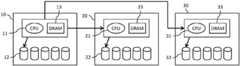
- FIG. 1is a system for data protection in which CPUs of storage servers control the storage of data.
- nodes 10 , 20 and 30are storage servers.
- Each node 10 , 20 , 30includes a CPU 11 , 21 , 31 , DRAM 13 , 23 , 33 , and one or more storage drives 12 , 22 , 32 .
- the one or more storage drives 12 , 22 , 32may be connected to their respective CPU 11 , 21 , 31 via a secondary port if the storage drive 12 , 22 , 32 is a dual-port storage device, a PCIe switch fabric, a network fabric, or other suitable connector.
- the CPU 11 of node 10issues a write command to local drive 12 of node 10 .
- the data to be storedis first cached in local DRAM 13 of node 10 before being stored on the local drive 12 .
- the CPU 11 of node 10initiates a write to remote drive 22 of node 20 with the same data to fulfill policy-based replication requirements.
- the CPU 11 of node 10initiates the CPU 21 of node 20 to store the data.
- the CPU 21issues a write command to the drive 22 via CPU 21 .
- the datais first cached in a local DRAM 23 of node 20 before being stored in the local drive 22 .
- a second writemay be configured with dual port drive(s) where the CPU 21 of node 20 is not involved.
- the CPU 11 of node 10may commit the data to additional drives on node 30 .
- the CPU 11may initiate the CPU of node 30 which then writes the data to its local drive 32 according to the same process as for node 20 .
- the server CPUs 11 , 21 , and 31orchestrate the data transfer.
- the transfer activitiesinvolve local CPU caches and DRAM along the data transfer path and require CPU power usage for storage across the various local drives.
- further softwaremay be required to synchronize the storage of data across the various nodes.
- storage server softwaremay coordinate both ends of the replication process in order to provide synchronous and asynchronous functionality.
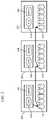
- FIG. 2is a schematic diagram of a drive-to-drive storage system according to an embodiment of the present invention.
- nodes 100 , 200 and 300are storage servers. Each node 100 , 200 and 300 includes a CPU 110 , 210 , 310 , DRAM 130 , 230 , 330 , and one or more storage drives 120 , 220 , 320 .
- the one or more storage drives 120 , 220 , 320may be SSDs.
- the one or more storage drives 120 , 220 , 320may be NVMe SSDs.
- CPUs 210 , 310 and DRAM 230 , 330may be excluded and nodes 200 , 300 may only include storage drives 220 , 320 .
- the one or more storage drives 120 , 220 , 320may be connected to their respective CPU 110 , 210 , 310 , for example, via a secondary port if the storage drive 120 , 220 , 320 is a dual-port storage device, a PCIe switch fabric, a network fabric, or other suitable connector.
- the storage drives 120 , 220 , 320can be connected to each other in a PCIe direct configuration, a switch fabric configuration or any other configuration in which the storage drives 120 , 220 , 320 are connected peer-to-peer.
- the storage drives 120 , 220 , 320can be connected to each other via a dedicated port or a reprogrammed switch port.
- the storage drives 120 , 220 , 320can communicate using either existing protocols or vendor specific implementations.
- connections and communication protocols as part of the peer-to-peer configurationcan drive direct memory access (DMA) requests and synchronization between the storage drives 120 , 220 , 320 , as described below.
- the storage drives 120 , 220 , 320can expose additional configuration options to be configured for peer-to-peer connectivity. Examples of such a configuration control path are get or set log_page (peer_config). This will be a new log page defined specifically for peer-to-peer logic. In some embodiments, the existing, well-known and standardized log page, the SMART log page, may be used.
- connections and communication protocols as part of the peer-to-peer configurationcan allow the storage drives 120 , 220 , 320 to communicate between each other, to be configured in dual mode, to share hardware resources enabling data transfers, and to provide a transport and signaling mechanism that may, in some embodiments, be vendor specific.
- FIG. 3is a schematic diagram of an embodiment of FIG. 2 in which the storage drives 120 , 220 , 320 are connected via a dedicated port or a reprogrammed switch port.
- the remote drives 220 , 320may be attached to separate CPUs 210 , 310 ; however, as shown in FIG. 3 , they need not have separate CPUs.
- the drives 220 , 320are termed as remote drives because they are not directly connected to the host CPU, but are instead connected to the host CPU 110 either through their own respective CPUs 220 , 320 or through another storage drive, such as the storage drive 120 .
- the storage server 100includes a root complex device 140 that connects the storage server 100 to a switch 150 , which is connected to the host storage drive 120 .
- the switch 150is also connected to switches 250 , 350 connected to storage drives 220 , 320 , respectively.
- the switches 150 , 250 , 350may be PCIe switches or other suitable dedicated or reprogrammed switch ports.
- the switches 150 , 250 , 350should support Access Control Services (ACS), if, for example, PCIe switches are used, or a suitable communication protocol to allow the storage drives 120 , 220 , 320 to communicate with one another and to share hardware resources for data transfers.
- ACSAccess Control Services
- the switches 150 , 250 , 350are network switches in a network fabric configuration
- the drives 120 , 220 , 320can be network attached directly to each other through a network protocol instead of PCIe. Memory accesses for synchronization in such an embodiment would be network memory mapped.
- the storage drives 120 , 220 , 320 of FIGS. 2 and 3can communicate to perform policy-based data transfers. This, in essence, creates a quality of service (QoS) channel between the storage drives 120 , 220 , 320 , as they are able to transfer data directly to each other.
- QoSquality of service
- the CPUs 110 , 210 , 310can manage the peer-to-peer connection between the storage drives 120 , 220 , 320 in a top-down configuration.
- the CPU 110 , 210 , 310 for a respective storage drive 120 , 220 , 320can manage the drive's peer access for pairing.
- the CPU 110 , 210 , 310can also program associated switches 150 , 250 , 350 between the storage drives 120 , 220 , 320 to allow for a peer-to-peer connection through the communication protocol used, for example, ACS, if PCIe switches are used.
- the CPU 110 , 210 , 310can program the network switches to allow for a peer-to-peer connection.
- the CPU 110can use a set log_page (peer_config) command to the storage drives 120 , 220 , 320 to instruct the storage drives 120 , 220 , 320 regarding their peer connectivity and the protection group.
- This commandis managed by the host CPU 110 and implemented in the drive and may only be required in the top-down configuration.
- the CPU 110 , 210 , 310 for a respective storage drive 120 , 220 , 320may also manage error paths.
- the storage drives 120 , 220 , 320can manage the peer-to-peer connection between the storage drives 120 , 220 , 320 in a bottom-up configuration.
- the storage drives 120 , 220 , 320can elect or otherwise provide a master controller with subordinate remote drives to form a self-managed cluster, for example, in a RAID formation.
- storage drive 120(hereafter referred to as the host drive 120 ) can act as a master controller for subordinate storage drives 220 , 320 .
- the host drive 120can consolidate storage pool resources providing one management view and, if desired, one address range.
- Software on the CPU 110can program the host drive 120 once the host drive 120 is on the cluster chain.
- the log_page commandcan specify and identify which drive is the host drive 120 and which are remote storage drives 220 , 320 .
- the host drive 120can control data flow and may include data in its local path or may push data from the CPU 110 directly to end storage devices 220 , 320 .
- An embodiment of the push modelmay use a RAID configuration.
- the host drive 120 connected to the CPU 110acts as the master controller that abstracts the LBA space and data movement.
- some LBA spacewill be local to the host drive 120 while other LBA space is on remote storage drives 220 , 320 .
- the data that is localwill be written to the host drive 120 while data in LBA ranges that are on remote storage drives 220 , 320 will be pushed to them.
- the host drive 120orchestrates the data movement.
- the remote drives 220 , 320can pull data to themselves.
- An embodiment of this pull modelmay use a RAID1 (replication) configuration in which control messages are pushed to the storage drives 120 , 220 , 320 and the data is pulled in by the remote storage drives 220 , 320 .
- Both the push and pull modelssynchronize the write traffic as per the data flow from the host CPU 110 .
- the host device 120can control logical block addressing (LBA) information and memory buffers at the host drive's control memory buffer 121 (see FIG. 4 ).
- LBAlogical block addressing
- the host drive 120can manage error and alternate paths and the CPU 110 can subscribe for error flow notifications that are managed by the host drive 120 .
- the host drive 120may expose errors only on the visible drives as normal error flows to the host CPU 110 . In other embodiments, the host drive 120 may make errors on those drives not visible and may only notify the host CPU 110 via special notifications that may require additional software.
- the storage drives 120 , 220 , 320In a bottom-up configuration, once the storage drives 120 , 220 , 320 are put into the peer-to-peer configuration for a policy-based data protection scheme, they will be driven autonomously independent (and in some cases transparent) to the host CPU 110 . In the latter case where the storage drives 120 , 220 , 320 are transparent to the host CPU 110 , an external mechanism is needed to discover, configure and modify the protection scheme. This may be achieved through, for example, a separate control plane, a BMC, or a switch management port, to name a few.
- the host drive 120includes software that can instruct the one or more remote storage devices 220 , 320 on the other storage servers 200 , 300 to be aware of the host drive 120 .
- the softwaremay store in the control memory buffer 122 of a DRAM 121 of the host storage device 120 , as shown in FIG. 4 .
- the control memory buffer 122is an NVMe drive definition which is a portion of the host drive's DRAM 121 memory that can be exposed to the host CPU 110 for data transfer mechanisms in embodiments of the current invention.
- the CMBcan be used to share control and data payload packets.
- the notificationitself is transport specific, e.g., TLPs for PCIe.
- This organizationallows a portion of the control memory buffer 122 of the host drive 120 to perform as a replication and data transfer staging area.
- the control memory buffer 122can be used by the host drive 120 to expose the data payload and synchronization memory pointers.
- the host drive 120will coordinate with the one or more remote storage devices 220 , 320 with its buffer management options and control, and the one or more remote storage devices 220 , 320 will respond similarly.
- the host drive 120will expose its buffer management scheme and its synchronization method in this way, implementing an effective buffer management.
- these mechanismsmay not strictly follow the specifications of existing protocols, such as NVMe, and thus may be implemented as private or vendor specific protocols.
- This peer-to-peer connectioneffectively offloads the host CPUs 110 , 210 , 310 , reducing host CPU computing requirements and helping to lower storage system latency as a result of reduced storage server CPU involvement in data transfers.
- FIG. 5is a flowchart depicting a method for storing data using the drive-to-drive storage system of FIG. 2 or 3 .
- the CPU 110 of node 100stores data in the host drive 120 in a manner similar to that described above regarding FIG. 1 .
- the CPU 110issues a write command (S 1 ) to the host drive 120 .
- the data to be storedis first cached in a local DRAM 130 of node 100 before being stored in the host drive 120 .
- the host drive 120uses a direct memory access (DMA) request to the host CPU 110 to send (S 2 ) the data to be written to its DRAM 121 , thus triggering the data currently in the host server's DRAM 130 to be written in the control memory buffer 122 of the host drive's DRAM 121 .
- DMAdirect memory access
- the host drive 120also triggers (S 3 , S 4 ) a notification to one or more remote drives 220 , 320 with information regarding the data to be written, its location and offset within the control memory buffer 112 , and additional details such as Namespace/LUN, LBA offset, number of bytes, and/or any other information regarding the data that may be needed to initiate storage.
- the notificationitself can be a wire message between the host drive 120 and the remote drives 220 , 320 .
- the host drive 120also sets a flag (for example, the host drive 120 can increment a reference count for each remote drive 220 , 320 it will write data to according to policy-based data protection scheme) indicating that the associated memory block(s) is referenced and should not be prematurely dereferenced for its own tracking.
- the one or more remote drives 220 , 320use the received information to construct and issue (S 5 , S 6 ) a DMA request to their respective memory ( 221 , 331 ) from the host drive control memory buffer 121 using the given information.
- the provided informatione.g., Namespace/LUN, LBA, number of bytes, etc.
- the associated one or more remote drives 220 , 320signal (S 7 , S 8 ) the completion to the host drive 120 , allowing the host drive 120 to decrement the reference count in the control memory buffer 122 . This may occur using a separate call or by DMA operations directly manipulating host drive memory pointers atomically.
- the entire process as described above regarding FIG. 5may proceed transparently to the storage server nodes 100 , 200 , 300 .
- the remote drives 220 , 320need not have enabled CMB. However, if remote drives 220 , 320 have CMBs and they are enabled, those respective CMBs can be used in the above-described push model to replicate the payload by the host drive 120 .
- data distributionmay be achieved in other ways, such as by a daisy-chain or torus manner instead of a host drive to one or more remote drives.
- daisy-chain and torus topologiesare switchless interconnects.
- the drivesare connected in series, with the host drive 120 connected to a first remote storage drive (e.g., the remote drive 220 ), the first remote storage drive connected to the next remote storage drive (e.g., the remote drive 320 ), and so forth for any number of storage drives included in the system.
- Drive-to-drive communicationis direct and need not follow a standards based protocol. Connections such as USB, FireWire, Thunderbolt and Ethernet are other examples used in a daisy-chain.
- each storage driveis directly connected to more than one of the other storage drives in a parallel system configuration and without a switch in between (1D, 2D, 3D, ND) the drives.
- the host drive 120is connected to both remote storage drives 220 and 320
- the storage drive 220is connected to the host drive 120 and the remote storage drive 320
- the remote storage drive 320is connected to both the host drive 120 and the remote storage drive 220 .
- the costcan also be decreased in such a topology due to reduced hardware requirements.
- the close proximity of the drives in this configurationcan lead to decreased latency and to scaling benefits.
- the drives 120 , 220 , 320may additionally construct a private network outside the control and even outside the view of storage server CPUs 110 , 210 , 310 .
- Choosing an existing communication protocolcan require adhering to all the requirements of the existing protocol, including corner cases and error conditions, which can require additional hardware/firmware resources in the host drive.
- the host drive and the one or more remote storage drivesare from one vendor, then some of the existing protocol restrictions can be relaxed by using a vendor-specific method that is not constrained. Examples of such private definitions are public NVMe over Fabrics (NVMe-oF) definitions and vendor specific implementations of NVMe, such as NVMe over Ethernet and NVMe over Network vendor specific implementations.
- NVMe-oFpublic NVMe over Fabrics
- MCTP over PCI Expresscan be redefined into a vendor-specific implementation by removing the DMFT specific definitions and its required compatibility, timing specifications. This makes it a stripped down version of the original definitions tailored for usage with embodiments of the present invention.
- a network interconnectmay be used to enable the host drive to talk directly to peered remote drive(s). This private network can likewise be streamlined with vendor specific definitions.
- private device connectivity as shown in the above examplescan be made vendor specific and unconstrained by public specifications allowing vendor-specific drive methods to communicate information more effectively between storage devices as compared to currently used protocol transfers, thereby providing consistent performance.
- the drivecan expose its atomicity down to the SSD's FTL layer and its Logical-to-Physical mapping (L2P) commit.
- L2PLogical-to-Physical mapping
- For replicationwhen a sample payload arrives at the host drive, it can delay the update to its mapping till all peered remote drives have synchronized to that write request. There will be an additional synchronization related message to update the flash L2P mapping that goes back to the peers if all of them have successfully committed the write. This is possible because the drive does not expose its internal configuration definition to external software and keeps it hidden between its peers and the vendor peers its IP on drive layout intact. This is one way atomicity can be achieved. Further, the above embodiments provide atomicity between data protection sample sets such as replication sample sets.
- the above embodimentsprovide a host storage device and method to allow the storage devices to address each other directly, without an intervening CPU, thereby offloading data movement activities that typically engage the server CPU.
- the storage serverscan potentially support a greater number of storage devices or the power of the CPUs can be decreased and still support the same number of storage devices.
- the above embodimentsalso simplify host software coordination between multiple drives, and the host software does not affect I/O performance and latency metrics once the storage device synchronization is setup, as the storage drives can perform data transfers without further involving the host system.
- Possible usages of the embodiments of the present inventioninclude, but are not limited to, data replication, snapshots for direct data, and Key Value type usages for indirect data.
Landscapes
- Engineering & Computer Science (AREA)
- Theoretical Computer Science (AREA)
- Physics & Mathematics (AREA)
- General Engineering & Computer Science (AREA)
- General Physics & Mathematics (AREA)
- Human Computer Interaction (AREA)
- Information Retrieval, Db Structures And Fs Structures Therefor (AREA)
- Bus Control (AREA)
- Information Transfer Systems (AREA)
- Vehicle Body Suspensions (AREA)
- Memory System Of A Hierarchy Structure (AREA)
- Automatic Disk Changers (AREA)
Abstract
Description
Claims (19)
Priority Applications (8)
| Application Number | Priority Date | Filing Date | Title |
|---|---|---|---|
| US15/957,773US11321249B2 (en) | 2018-03-26 | 2018-04-19 | Mechanism to autonomously manage SSDS in an array |
| KR1020180154812AKR102705791B1 (en) | 2018-03-26 | 2018-12-04 | Mechanism to autonomously manage ssds in an array |
| TW107145535ATWI795491B (en) | 2018-03-26 | 2018-12-18 | Drive-to-drive storage system, storage drive and method for storing data |
| JP2019043503AJP7311280B2 (en) | 2018-03-26 | 2019-03-11 | Storage system and its host storage drive and data storage method |
| CN201910223119.8ACN110362515B (en) | 2018-03-26 | 2019-03-22 | Drive-to-drive storage system, storage drive, and method of storing data |
| US17/734,908US11775454B2 (en) | 2018-03-26 | 2022-05-02 | Mechanism to autonomously manage SSDs in an array |
| US18/373,711US12174762B2 (en) | 2018-03-26 | 2023-09-27 | Mechanism to autonomously manage SSDs in an array |
| US18/940,613US20250061068A1 (en) | 2018-03-26 | 2024-11-07 | Mechanism to autonomously manage ssds in an array |
Applications Claiming Priority (2)
| Application Number | Priority Date | Filing Date | Title |
|---|---|---|---|
| US201862648292P | 2018-03-26 | 2018-03-26 | |
| US15/957,773US11321249B2 (en) | 2018-03-26 | 2018-04-19 | Mechanism to autonomously manage SSDS in an array |
Related Child Applications (1)
| Application Number | Title | Priority Date | Filing Date |
|---|---|---|---|
| US17/734,908ContinuationUS11775454B2 (en) | 2018-03-26 | 2022-05-02 | Mechanism to autonomously manage SSDs in an array |
Publications (2)
| Publication Number | Publication Date |
|---|---|
| US20190294565A1 US20190294565A1 (en) | 2019-09-26 |
| US11321249B2true US11321249B2 (en) | 2022-05-03 |
Family
ID=67985075
Family Applications (4)
| Application Number | Title | Priority Date | Filing Date |
|---|---|---|---|
| US15/957,773Active2038-05-20US11321249B2 (en) | 2018-03-26 | 2018-04-19 | Mechanism to autonomously manage SSDS in an array |
| US17/734,908ActiveUS11775454B2 (en) | 2018-03-26 | 2022-05-02 | Mechanism to autonomously manage SSDs in an array |
| US18/373,711ActiveUS12174762B2 (en) | 2018-03-26 | 2023-09-27 | Mechanism to autonomously manage SSDs in an array |
| US18/940,613PendingUS20250061068A1 (en) | 2018-03-26 | 2024-11-07 | Mechanism to autonomously manage ssds in an array |
Family Applications After (3)
| Application Number | Title | Priority Date | Filing Date |
|---|---|---|---|
| US17/734,908ActiveUS11775454B2 (en) | 2018-03-26 | 2022-05-02 | Mechanism to autonomously manage SSDs in an array |
| US18/373,711ActiveUS12174762B2 (en) | 2018-03-26 | 2023-09-27 | Mechanism to autonomously manage SSDs in an array |
| US18/940,613PendingUS20250061068A1 (en) | 2018-03-26 | 2024-11-07 | Mechanism to autonomously manage ssds in an array |
Country Status (5)
| Country | Link |
|---|---|
| US (4) | US11321249B2 (en) |
| JP (1) | JP7311280B2 (en) |
| KR (1) | KR102705791B1 (en) |
| CN (1) | CN110362515B (en) |
| TW (1) | TWI795491B (en) |
Cited By (1)
| Publication number | Priority date | Publication date | Assignee | Title |
|---|---|---|---|---|
| US20220327068A1 (en)* | 2018-03-26 | 2022-10-13 | Samsung Electronics Co., Ltd. | Mechanism to autonomously manage ssds in an array |
Families Citing this family (11)
| Publication number | Priority date | Publication date | Assignee | Title |
|---|---|---|---|---|
| US11954220B2 (en) | 2018-05-21 | 2024-04-09 | Pure Storage, Inc. | Data protection for container storage |
| US12086431B1 (en)* | 2018-05-21 | 2024-09-10 | Pure Storage, Inc. | Selective communication protocol layering for synchronous replication |
| US12181981B1 (en) | 2018-05-21 | 2024-12-31 | Pure Storage, Inc. | Asynchronously protecting a synchronously replicated dataset |
| US10846020B2 (en)* | 2018-11-02 | 2020-11-24 | Dell Products L.P. | Drive assisted storage controller system and method |
| US11048447B2 (en)* | 2019-10-17 | 2021-06-29 | International Business Machines Corporation | Providing direct data access between accelerators and storage in a computing environment, wherein the direct data access is independent of host CPU and the host CPU transfers object map identifying object of the data |
| US11316917B2 (en) | 2020-03-04 | 2022-04-26 | Samsung Electronics Co., Ltd. | Methods and apparatus for peer-to-peer data channels for storage devices |
| US11656795B2 (en)* | 2021-01-21 | 2023-05-23 | EMC IP Holding Company LLC | Indicating optimized and non-optimized paths to hosts using NVMe-oF in a metro cluster storage system |
| US12014052B2 (en)* | 2021-03-22 | 2024-06-18 | Google Llc | Cooperative storage architecture |
| US20240020030A1 (en)* | 2022-07-14 | 2024-01-18 | Dell Products L.P. | System and method of utilizing nonvolatile memory media associated with an information handling system |
| US12072795B1 (en) | 2023-03-14 | 2024-08-27 | Dell Products L.P. | Providing access to a namespace via multiple storage arrays |
| US12223212B1 (en)* | 2023-08-02 | 2025-02-11 | Dell Products L.P. | Software raid/management communication system |
Citations (23)
| Publication number | Priority date | Publication date | Assignee | Title |
|---|---|---|---|---|
| US5325489A (en)* | 1991-07-15 | 1994-06-28 | Nec Corporation | Data transfer control device using direct memory access |
| KR20000021045A (en) | 1998-09-25 | 2000-04-15 | 차동해 | Method and system for performing dual operating of computer control |
| JP2005293435A (en) | 2004-04-05 | 2005-10-20 | Konica Minolta Business Technologies Inc | Data transfer device and its setting method |
| US7334076B2 (en)* | 2005-03-08 | 2008-02-19 | Microsoft Corporation | Method and system for a guest physical address virtualization in a virtual machine environment |
| US20140181435A1 (en) | 2012-12-20 | 2014-06-26 | Kenneth W. Privitt | Multiple computer system processing write data outside of checkpointing |
| US20150026368A1 (en)* | 2013-07-17 | 2015-01-22 | Mellanox Technologies Ltd. | Direct memory access to storage devices |
| US20150278246A1 (en) | 2013-02-20 | 2015-10-01 | Panasonic Intellectual Property Management Co., Ltd. | Wireless access device and wireless access system |
| US20160188500A1 (en)* | 2014-12-25 | 2016-06-30 | Intel Corporation | Packed write completions |
| US20160357443A1 (en)* | 2015-06-05 | 2016-12-08 | University Of Florida Research Foundation, Incorporated | Method and apparatus for big data cloud storage resource management |
| US20170024334A1 (en)* | 2013-04-17 | 2017-01-26 | Apeiron Data Systems | Method and apparatus for accessing multiple storage devices from multiple hosts without use of remote direct memory access (rdma) |
| CN106557429A (en) | 2015-09-29 | 2017-04-05 | 华为技术有限公司 | A kind of moving method and Node Controller of internal storage data |
| US20170300433A1 (en)* | 2014-10-29 | 2017-10-19 | Hewlett Packard Enterprise Development Lp | Trans-fabric instruction set for a communication fabric |
| US9817607B1 (en) | 2014-06-20 | 2017-11-14 | EMC IP Holding Company LLC | Optimizations to avoid intersocket links |
| US20170357609A1 (en)* | 2016-06-10 | 2017-12-14 | Liqid Inc. | Multi-Port Interposer Architectures In Data Storage Systems |
| US20180027680A1 (en)* | 2016-07-22 | 2018-01-25 | Mohan J. Kumar | Dynamic Memory for Compute Resources in a Data Center |
| US20180095871A1 (en)* | 2016-10-04 | 2018-04-05 | Pure Storage, Inc. | Peer-to-peer non-volatile random-access memory |
| US20180189207A1 (en)* | 2011-09-30 | 2018-07-05 | Intel Corporation | Memory channel that supports near memory and far memory access |
| US10079889B1 (en)* | 2014-11-04 | 2018-09-18 | Pavilion Data Systems, Inc. | Remotely accessible solid state drive |
| US20180341606A1 (en)* | 2017-05-25 | 2018-11-29 | Western Digital Technologies, Inc. | Offloaded Disaggregated Storage Architecture |
| US20190034306A1 (en)* | 2017-07-31 | 2019-01-31 | Intel Corporation | Computer System, Computer System Host, First Storage Device, Second Storage Device, Controllers, Methods, Apparatuses and Computer Programs |
| US10216666B2 (en)* | 2014-11-04 | 2019-02-26 | Cavium, Llc | Caching methods and systems using a network interface card |
| US20190250852A1 (en)* | 2018-02-15 | 2019-08-15 | Seagate Technology Llc | Distributed compute array in a storage system |
| US20190294339A1 (en)* | 2018-03-21 | 2019-09-26 | Western Digital Technologies, Inc. | Data Storage System Scale-Out with Local Address Remapping |
Family Cites Families (25)
| Publication number | Priority date | Publication date | Assignee | Title |
|---|---|---|---|---|
| JP3617437B2 (en)* | 2000-09-13 | 2005-02-02 | 日本電気株式会社 | Data copy method and program recording medium recording data copy program |
| CN101187849A (en)* | 2003-07-07 | 2008-05-28 | 日立超大规模集成电路系统株式会社 | Storage device and storage system |
| US7660943B2 (en)* | 2006-02-17 | 2010-02-09 | International Business Machines Corporation | Data storage drive for automated data storage library |
| US9331955B2 (en) | 2011-06-29 | 2016-05-03 | Microsoft Technology Licensing, Llc | Transporting operations of arbitrary size over remote direct memory access |
| US9158461B1 (en)* | 2012-01-18 | 2015-10-13 | Western Digital Technologies, Inc. | Measuring performance of data storage systems |
| US10651975B2 (en)* | 2012-08-02 | 2020-05-12 | Pure Storage, Inc. | Forwarding data amongst cooperative DSTN processing units of a massive data ingestion system |
| ES2779551T3 (en)* | 2013-10-29 | 2020-08-18 | Huawei Tech Co Ltd | Data processing system and data processing method |
| WO2015138245A1 (en) | 2014-03-08 | 2015-09-17 | Datawise Systems, Inc. | Methods and systems for converged networking and storage |
| US9727503B2 (en)* | 2014-03-17 | 2017-08-08 | Mellanox Technologies, Ltd. | Storage system and server |
| US10114784B2 (en) | 2014-04-25 | 2018-10-30 | Liqid Inc. | Statistical power handling in a scalable storage system |
| US9294567B2 (en) | 2014-05-02 | 2016-03-22 | Cavium, Inc. | Systems and methods for enabling access to extensible storage devices over a network as local storage via NVME controller |
| WO2015200313A1 (en)* | 2014-06-23 | 2015-12-30 | Liqid Inc. | Modular switched fabric for data storage systems |
| US9712619B2 (en)* | 2014-11-04 | 2017-07-18 | Pavilion Data Systems, Inc. | Virtual non-volatile memory express drive |
| JP6517549B2 (en)* | 2015-03-13 | 2019-05-22 | 東芝メモリ株式会社 | Memory controller, storage device, data transfer system, data transfer method, and data transfer program |
| US9892071B2 (en)* | 2015-08-03 | 2018-02-13 | Pure Storage, Inc. | Emulating a remote direct memory access (‘RDMA’) link between controllers in a storage array |
| WO2017040706A1 (en)* | 2015-09-02 | 2017-03-09 | Cnex Labs, Inc. | Nvm express controller for remote access of memory and i/o over ethernet-type networks |
| US10083144B2 (en)* | 2015-09-30 | 2018-09-25 | International Business Machines Corporation | Programming interface operations in a port in communication with a driver for reinitialization of storage controller elements |
| US10223313B2 (en) | 2016-03-07 | 2019-03-05 | Quanta Computer Inc. | Scalable pooled NVMe storage box that comprises a PCIe switch further connected to one or more switches and switch ports |
| ES2714804T3 (en) | 2016-07-06 | 2019-05-30 | Nestec Sa | Recyclable container comprising a flexible bag |
| KR102683728B1 (en)* | 2016-07-22 | 2024-07-09 | 삼성전자주식회사 | Method of achieving low write latency in a data starage system |
| US10423487B2 (en)* | 2016-08-19 | 2019-09-24 | Samsung Electronics Co., Ltd. | Data protection offloads using SSD peering |
| US11138103B1 (en)* | 2017-06-11 | 2021-10-05 | Pure Storage, Inc. | Resiliency groups |
| US11321249B2 (en)* | 2018-03-26 | 2022-05-03 | Samsung Electronics Co., Ltd. | Mechanism to autonomously manage SSDS in an array |
| US10678433B1 (en)* | 2018-04-27 | 2020-06-09 | Pure Storage, Inc. | Resource-preserving system upgrade |
| US11385792B2 (en)* | 2018-04-27 | 2022-07-12 | Pure Storage, Inc. | High availability controller pair transitioning |
- 2018
- 2018-04-19USUS15/957,773patent/US11321249B2/enactiveActive
- 2018-12-04KRKR1020180154812Apatent/KR102705791B1/enactiveActive
- 2018-12-18TWTW107145535Apatent/TWI795491B/enactive
- 2019
- 2019-03-11JPJP2019043503Apatent/JP7311280B2/enactiveActive
- 2019-03-22CNCN201910223119.8Apatent/CN110362515B/enactiveActive
- 2022
- 2022-05-02USUS17/734,908patent/US11775454B2/enactiveActive
- 2023
- 2023-09-27USUS18/373,711patent/US12174762B2/enactiveActive
- 2024
- 2024-11-07USUS18/940,613patent/US20250061068A1/enactivePending
Patent Citations (24)
| Publication number | Priority date | Publication date | Assignee | Title |
|---|---|---|---|---|
| US5325489A (en)* | 1991-07-15 | 1994-06-28 | Nec Corporation | Data transfer control device using direct memory access |
| KR20000021045A (en) | 1998-09-25 | 2000-04-15 | 차동해 | Method and system for performing dual operating of computer control |
| JP2005293435A (en) | 2004-04-05 | 2005-10-20 | Konica Minolta Business Technologies Inc | Data transfer device and its setting method |
| US7334076B2 (en)* | 2005-03-08 | 2008-02-19 | Microsoft Corporation | Method and system for a guest physical address virtualization in a virtual machine environment |
| US20190018809A1 (en)* | 2011-09-30 | 2019-01-17 | Intel Corporation | Memory channel that supports near memory and far memory access |
| US20180189207A1 (en)* | 2011-09-30 | 2018-07-05 | Intel Corporation | Memory channel that supports near memory and far memory access |
| US20140181435A1 (en) | 2012-12-20 | 2014-06-26 | Kenneth W. Privitt | Multiple computer system processing write data outside of checkpointing |
| US20150278246A1 (en) | 2013-02-20 | 2015-10-01 | Panasonic Intellectual Property Management Co., Ltd. | Wireless access device and wireless access system |
| US20170024334A1 (en)* | 2013-04-17 | 2017-01-26 | Apeiron Data Systems | Method and apparatus for accessing multiple storage devices from multiple hosts without use of remote direct memory access (rdma) |
| US20150026368A1 (en)* | 2013-07-17 | 2015-01-22 | Mellanox Technologies Ltd. | Direct memory access to storage devices |
| US9817607B1 (en) | 2014-06-20 | 2017-11-14 | EMC IP Holding Company LLC | Optimizations to avoid intersocket links |
| US20170300433A1 (en)* | 2014-10-29 | 2017-10-19 | Hewlett Packard Enterprise Development Lp | Trans-fabric instruction set for a communication fabric |
| US10216666B2 (en)* | 2014-11-04 | 2019-02-26 | Cavium, Llc | Caching methods and systems using a network interface card |
| US10079889B1 (en)* | 2014-11-04 | 2018-09-18 | Pavilion Data Systems, Inc. | Remotely accessible solid state drive |
| US20160188500A1 (en)* | 2014-12-25 | 2016-06-30 | Intel Corporation | Packed write completions |
| US20160357443A1 (en)* | 2015-06-05 | 2016-12-08 | University Of Florida Research Foundation, Incorporated | Method and apparatus for big data cloud storage resource management |
| CN106557429A (en) | 2015-09-29 | 2017-04-05 | 华为技术有限公司 | A kind of moving method and Node Controller of internal storage data |
| US20170357609A1 (en)* | 2016-06-10 | 2017-12-14 | Liqid Inc. | Multi-Port Interposer Architectures In Data Storage Systems |
| US20180027680A1 (en)* | 2016-07-22 | 2018-01-25 | Mohan J. Kumar | Dynamic Memory for Compute Resources in a Data Center |
| US20180095871A1 (en)* | 2016-10-04 | 2018-04-05 | Pure Storage, Inc. | Peer-to-peer non-volatile random-access memory |
| US20180341606A1 (en)* | 2017-05-25 | 2018-11-29 | Western Digital Technologies, Inc. | Offloaded Disaggregated Storage Architecture |
| US20190034306A1 (en)* | 2017-07-31 | 2019-01-31 | Intel Corporation | Computer System, Computer System Host, First Storage Device, Second Storage Device, Controllers, Methods, Apparatuses and Computer Programs |
| US20190250852A1 (en)* | 2018-02-15 | 2019-08-15 | Seagate Technology Llc | Distributed compute array in a storage system |
| US20190294339A1 (en)* | 2018-03-21 | 2019-09-26 | Western Digital Technologies, Inc. | Data Storage System Scale-Out with Local Address Remapping |
Cited By (4)
| Publication number | Priority date | Publication date | Assignee | Title |
|---|---|---|---|---|
| US20220327068A1 (en)* | 2018-03-26 | 2022-10-13 | Samsung Electronics Co., Ltd. | Mechanism to autonomously manage ssds in an array |
| US11775454B2 (en)* | 2018-03-26 | 2023-10-03 | Samsung Electronics Co., Ltd. | Mechanism to autonomously manage SSDs in an array |
| US20240020247A1 (en)* | 2018-03-26 | 2024-01-18 | Samsung Electronics Co., Ltd. | Mechanism to autonomously manage ssds in an array |
| US12174762B2 (en)* | 2018-03-26 | 2024-12-24 | Samsung Electronics Co., Ltd. | Mechanism to autonomously manage SSDs in an array |
Also Published As
| Publication number | Publication date |
|---|---|
| KR102705791B1 (en) | 2024-09-12 |
| US20250061068A1 (en) | 2025-02-20 |
| JP7311280B2 (en) | 2023-07-19 |
| CN110362515B (en) | 2024-11-26 |
| TW201945946A (en) | 2019-12-01 |
| JP2019175445A (en) | 2019-10-10 |
| US20240020247A1 (en) | 2024-01-18 |
| US20190294565A1 (en) | 2019-09-26 |
| US11775454B2 (en) | 2023-10-03 |
| US20220327068A1 (en) | 2022-10-13 |
| KR20190112626A (en) | 2019-10-07 |
| US12174762B2 (en) | 2024-12-24 |
| TWI795491B (en) | 2023-03-11 |
| CN110362515A (en) | 2019-10-22 |
Similar Documents
| Publication | Publication Date | Title |
|---|---|---|
| US12174762B2 (en) | Mechanism to autonomously manage SSDs in an array | |
| CN113810312B (en) | Systems and methods for managing memory resources | |
| US11416431B2 (en) | System with cache-coherent memory and server-linking switch | |
| CN116501681B (en) | CXL data transmission board card and method for controlling data transmission | |
| CN108351813B (en) | Method and apparatus for enabling individual non-volatile memory express (NVMe) input/output (IO) queues on different network addresses of NVMe controller | |
| CN110941576B (en) | System, method and device for memory controller with multi-mode PCIE function | |
| US11194743B2 (en) | Method of accessing a dual line SSD device through PCIe EP and network interface simultaneously | |
| US12079506B2 (en) | Memory expander, host device using memory expander, and operation method of sever system including memory expander | |
| WO2020233435A1 (en) | Data processing method, apparatus, and system | |
| CN107209725A (en) | Method, processor and the computer of processing write requests | |
| EP4278268B1 (en) | Dual-port memory module design for composable computing | |
| US11194746B2 (en) | Exchanging drive information | |
| JP7752489B2 (en) | Systems and methods for managing memory resources | |
| Gupta et al. | Gen-Z emerging technology for memory intensive applications | |
| US20190303316A1 (en) | Hardware based virtual memory management |
Legal Events
| Date | Code | Title | Description |
|---|---|---|---|
| AS | Assignment | Owner name:SAMSUNG ELECTRONICS CO., LTD, KOREA, REPUBLIC OF Free format text:ASSIGNMENT OF ASSIGNORS INTEREST;ASSIGNORS:PINTO, OSCAR P.;BRENNAN, ROBERT;SIGNING DATES FROM 20180418 TO 20180419;REEL/FRAME:045593/0770 | |
| FEPP | Fee payment procedure | Free format text:ENTITY STATUS SET TO UNDISCOUNTED (ORIGINAL EVENT CODE: BIG.); ENTITY STATUS OF PATENT OWNER: LARGE ENTITY | |
| STPP | Information on status: patent application and granting procedure in general | Free format text:NON FINAL ACTION MAILED | |
| STPP | Information on status: patent application and granting procedure in general | Free format text:RESPONSE TO NON-FINAL OFFICE ACTION ENTERED AND FORWARDED TO EXAMINER | |
| STPP | Information on status: patent application and granting procedure in general | Free format text:FINAL REJECTION MAILED | |
| STPP | Information on status: patent application and granting procedure in general | Free format text:ADVISORY ACTION MAILED | |
| STPP | Information on status: patent application and granting procedure in general | Free format text:DOCKETED NEW CASE - READY FOR EXAMINATION | |
| STPP | Information on status: patent application and granting procedure in general | Free format text:NOTICE OF ALLOWANCE MAILED -- APPLICATION RECEIVED IN OFFICE OF PUBLICATIONS | |
| STPP | Information on status: patent application and granting procedure in general | Free format text:PUBLICATIONS -- ISSUE FEE PAYMENT RECEIVED | |
| STPP | Information on status: patent application and granting procedure in general | Free format text:PUBLICATIONS -- ISSUE FEE PAYMENT VERIFIED | |
| STCF | Information on status: patent grant | Free format text:PATENTED CASE |