US11320916B2 - Pen holding devices - Google Patents
Pen holding devicesDownload PDFInfo
- Publication number
- US11320916B2 US11320916B2US16/092,112US201616092112AUS11320916B2US 11320916 B2US11320916 B2US 11320916B2US 201616092112 AUS201616092112 AUS 201616092112AUS 11320916 B2US11320916 B2US 11320916B2
- Authority
- US
- United States
- Prior art keywords
- pen
- holding device
- standardized interface
- receiver
- standardized
- Prior art date
- Legal status (The legal status is an assumption and is not a legal conclusion. Google has not performed a legal analysis and makes no representation as to the accuracy of the status listed.)
- Active, expires
Links
Images


Classifications
- B—PERFORMING OPERATIONS; TRANSPORTING
- B43—WRITING OR DRAWING IMPLEMENTS; BUREAU ACCESSORIES
- B43K—IMPLEMENTS FOR WRITING OR DRAWING
- B43K29/00—Combinations of writing implements with other articles
- B43K29/20—Combinations of writing implements with other articles with other articles having storage compartments
- G—PHYSICS
- G06—COMPUTING OR CALCULATING; COUNTING
- G06F—ELECTRIC DIGITAL DATA PROCESSING
- G06F3/00—Input arrangements for transferring data to be processed into a form capable of being handled by the computer; Output arrangements for transferring data from processing unit to output unit, e.g. interface arrangements
- G06F3/01—Input arrangements or combined input and output arrangements for interaction between user and computer
- G06F3/03—Arrangements for converting the position or the displacement of a member into a coded form
- G06F3/033—Pointing devices displaced or positioned by the user, e.g. mice, trackballs, pens or joysticks; Accessories therefor
- G06F3/0354—Pointing devices displaced or positioned by the user, e.g. mice, trackballs, pens or joysticks; Accessories therefor with detection of 2D relative movements between the device, or an operating part thereof, and a plane or surface, e.g. 2D mice, trackballs, pens or pucks
- G06F3/03545—Pens or stylus
- B—PERFORMING OPERATIONS; TRANSPORTING
- B43—WRITING OR DRAWING IMPLEMENTS; BUREAU ACCESSORIES
- B43K—IMPLEMENTS FOR WRITING OR DRAWING
- B43K25/00—Attaching writing implements to wearing apparel or objects involving constructional changes of the implements
- B43K25/02—Clips
- B—PERFORMING OPERATIONS; TRANSPORTING
- B43—WRITING OR DRAWING IMPLEMENTS; BUREAU ACCESSORIES
- B43L—ARTICLES FOR WRITING OR DRAWING UPON; WRITING OR DRAWING AIDS; ACCESSORIES FOR WRITING OR DRAWING
- B43L27/00—Ink stands
- B43L27/02—Ink stands having means for securing objects thereon
- B—PERFORMING OPERATIONS; TRANSPORTING
- B43—WRITING OR DRAWING IMPLEMENTS; BUREAU ACCESSORIES
- B43L—ARTICLES FOR WRITING OR DRAWING UPON; WRITING OR DRAWING AIDS; ACCESSORIES FOR WRITING OR DRAWING
- B43L27/00—Ink stands
- B43L27/04—Ink stands securable to other objects
- G—PHYSICS
- G06—COMPUTING OR CALCULATING; COUNTING
- G06F—ELECTRIC DIGITAL DATA PROCESSING
- G06F2200/00—Indexing scheme relating to G06F1/04 - G06F1/32
- G06F2200/16—Indexing scheme relating to G06F1/16 - G06F1/18
- G06F2200/163—Indexing scheme relating to constructional details of the computer
- G06F2200/1632—Pen holder integrated in the computer
- G—PHYSICS
- G06—COMPUTING OR CALCULATING; COUNTING
- G06F—ELECTRIC DIGITAL DATA PROCESSING
- G06F2200/00—Indexing scheme relating to G06F1/04 - G06F1/32
- G06F2200/16—Indexing scheme relating to G06F1/16 - G06F1/18
- G06F2200/163—Indexing scheme relating to constructional details of the computer
- G06F2200/1635—Stackable modules
Definitions
- An electronic devicemay allow a user to input commands via a number of different devices.
- the number of different devicesmay include a computer keyboard, a computer mouse, and a pen that can be mechanically and/or electronically coupled to the electronic device.
- FIG. 1illustrates an example of a pen holding device according to the disclosure.
- FIGS. 2A and 2Billustrate an example of a pen holding device according to the disclosure.
- FIG. 3illustrates an example of a pen holding device with a snap feature according to the disclosure.
- FIG. 4illustrates an example of a system including a pen holding device according to the disclosure.
- FIG. 5illustrates an example of a pen holding device with a plurality of connectors according to the disclosure.
- a pen holding devicemay be coupled to an electronic device and receive and couple to a pen.
- a usercan attach and detach the pen from the pen holding device for use with the electronic device.
- the usermay use the pen to input a number of commands to the electronic device via the pen.
- the pen holding devicemay include a particular coupling mechanism to couple the pen to the pen holding device.
- the pen holding devicemay include a magnet to provide a magnetic coupling between the pen and the pen holding device.
- a particular coupling mechanismmay not be securely couple the pen to the pen holding device.
- mere magnetic couplingmay allow for free orientation (i.e., movement of the pen) of the pen along a longitudinal axis of the pen and/or such free orientation may weaken the magnetic coupling between the pen and the pen holding device.
- the penmay be inadvertently detached from the pen holding device.
- a pen holding devicecan include a connector coupled to a receiver to couple the pen holding device to an electronic device, and the receiver including a magnet and a pen clip holder to couple a pen (e.g., a stylus or other type of pen) via the magnet and the pen clip holder.
- the pen holding deviceas described herein, can strengthen the coupling between the pen and the pen holding device by providing two or more coupling mechanisms such as a magnetic coupling and a frictional coupling that are employed at the same time.
- a frictional couplingrefers to a coupling between a pen and a pen holding device, in which the pen holding device is to, when coupled to the pen, limit movement of the pen within the pen holding device via a frictional force.
- a magnetic couplingrefers to a coupling between a pen and a pen holding device, in which the pen holding device is to, when coupled to the pen, limit movement of the pen within the pen holding device via a magnetic force.
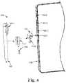
- FIG. 1illustrates an example of a pen holding device 110 according to the disclosure.
- the pen holding device 110can comprise a connector 110 - 2 coupled to a receiver 110 - 1 to couple the pen holding device 110 to an electronic device (not shown), and the receiver 110 - 1 including a magnet 115 and a pen clip holder (not shown) to couple a pen 120 via the magnet and the pen clip holder (not shown).
- the receiver 110 - 1can include a magnet 115 to couple the pen 120 to the receiver 110 - 1 .
- the receiver 110 - 1can include the magnet 115 .
- the magnet 115 coupled to the receiver 110 - 1can provide a magnetic coupling between the receiver 110 - 1 and the pen 120 .
- the pen 120can be formed at least in part of a metal (e.g., steel, etc.) that is readily coupled to the magnet 115 .
- the pen 120can be a stylus to interact with an electronic device and/or another type of pen such as those including ink or other writing materials.
- the magnet 115can be positioned adjacent to the pen clip holder to couple the pen via both the magnet and the pen clip holder at the same time. For example, when the pen 120 is being coupled to the pen clip holder 110 , the magnetic coupling and the frictional coupling can occur at the same time as the magnet 115 is positioned adjacent to the pen clip holder.
- the receiver 110 - 1can include a pen clip holder (not shown in FIG. 1 ) to couple the pen 120 to the receiver 110 - 1 .
- the receiver 110 - 1can include the pen clip holder to couple a pen clip 120 - 1 of the pen 120 .
- the pen holding devicecan strengthen the coupling between the pen 120 and the pen holding device 110 in contrast to other approaches that may employ a lone type of coupling mechanism by itself.
- the receiver 110 - 1can be unremovably coupled to the connector 110 - 2 to prevent a disassembly of the pen holding device.
- the pen holding device 110as described in FIG. 1 , can comprise two different components: the receiver 110 - 1 and the connector 110 - 2 that can be coupled to each other in an unremovable manner (i.e., nonremovably coupled).
- the pen holding device 110can comprise a plastic connector (e.g., a connector 110 - 2 ) and a metal receiver (e.g., a receiver 110 - 1 ), in which the metal receiver is insert-molded into the plastic receiver to form a pen holding device.
- the plastic connectorcan be glued to the metal receiver.
- the pen holding device 110can be a continuous metal body that is manufactured by a computer numeric control (CNC) machine.
- CNCcomputer numeric control
- the receiver 110 - 1includes a snap feature (not shown) to couple and detach the pen, as describe herein.
- the snap feature of the receiver 110 - 1can flexibly open wide to couple the pen 120 , and restore its original state once the pen 120 is coupled to the receiver 110 - 1 .
- the connector 110 - 2includes a flexible end 112 forming a flexible U-shaped end disposable against a surface of a standardized interface of the electronic device to removably couple the pen holding device 110 to the electronic device (not shown).
- the connector 110 - 2can include a connector 112 that is a U-shaped and flexible, as described herein.
- the flexible end 112when being coupled to the standardized interface, can be compressed to be deformably coupled to the standardized interface by exerting spring tension against the surface of the standardized interface. When decoupled from the standardized interface the flexible end 112 can restore to its original state/shape.
- FIGS. 2A and 2Billustrate an example of a pen holding device 210 according to the disclosure.
- the pen holding device 210 illustrated in FIGS. 2A and 2Bcan be analogous to the pen holding device 110 as illustrated in FIG. 1 .
- the receiver 220 - 1 and the connector 210 - 2 of the pen holding device 210 illustrated in FIGS. 2A and 2Bare analogous to the receiver 110 - 1 and the connector 110 - 2 of the pen holding device 110 as illustrated in FIG. 1 , respectively.
- FIG. 2Aillustrates an example of the pen holding device 210 with a pen clip holder 214 .
- the receiver 210 - 1can couple a pen clip of the pen (not shown) to provide additional frictional coupling via the pen clip holder 214 .
- the pen clip holder 214can be specialized in coupling the pen clip (e.g., a pen clip 120 - 1 ).
- the pen holding device 210can be designed to fit for the pen (not shown) such that frictional force that may exerted to the pen while the pen (not shown) is coupled to the pen holding device.
- the pen clip holder 214can further strengthen the frictional coupling as described herein.
- FIG. 2Billustrates an example of a pen holding device 210 according to the disclosure.
- the receiver 210 - 1can couple the pen (not shown) moving along an axis 240 , as described herein.
- the pen (not shown)can be slidely inserted into the receiver 210 - 1 along the axis 240 such that the pen (not shown) can be coupled to the receiver 210 - 1 .
- the receiver 210 - 1can couple the pen (not shown) moving along an axis perpendicular to the axis 240 .
- the receiver 210 - 1can include a snap feature to flexibly coupe the pen (not shown) moving along the axis perpendicular to axis 240 , and to provide the coupling between the receiver 210 - 1 and the pen (not shown), as described herein.
- the receivercan, upon coupling the pen clip, limit an orientation of the pen along a longitudinal axis 240 of the pen to secure the coupling between the pen and the receiver.
- a pen holding device without a pen clip holdere.g., 240
- the penmay be inadvertently detached from the pen holding device.
- the pen holding device 210may secure the coupling between the pen holding device 210 and the pen.
- the pen holding device 210may include the pen clip holder 240 without a magnet 215 that provides the magnetic coupling.
- the connector 210 - 2may couple the pen to the pen holding device 210 via the pen clip holder 214 without the magnet 215 such that the pen can be coupled to the pen holding device 210 via the frictional coupling without the magnetic coupling.
- a length of the connector 210 - 2 along the longitudinal axis 240can be designed to provide a stronger frictional coupling between the pen holding device 210 and the pen.
- the length of the connector 210 - 2can be extended along the longitudinal axis 240 to provide more surface area of the connector 210 - 2 that can be in contact with the pen. By providing more surface area, the pen holding device 210 - 2 can limit the orientation of the pen coupled to the pen holding device 210 - 2 along the longitudinal axis 240 without a pen clip holder 214 .
- the connector 210 - 2can couple the pen holding device 210 to the electronic device (not shown) via a standardized interface of the electronic device.
- the connector 210 - 2can include a flexible end 212 disposable against a surface of a standardized interface (not shown) of the electronic device to removably couple the pen holding device 210 to the electronic device (not shown).
- the flexible end 212when being coupled to the standardized interface, can be compressed to be deformably coupled to the standardized interface, and restore its original state upon completing the coupling to exert spring tension by disposing itself against the surface of the standardized interface.
- the flexible endas illustrated in FIG. 2A , can form a U-shaped end.
- a receiving surface of the receiver 210 - 1can be concave.
- the receiving surface of the receiver 210 - 1 that can, when coupled to the pen, be in contact with the pencan be concave such that the pen with a circular longitudinal surface can fit to the receiving surface of the receiver 210 - 1 .
- the magnet 215 that can be included in the receiver 210 - 1can also be a curved-shape (e.g., concave) to fit into the concave-shaped receiver 210 - 1 , and to provide more surface area of the magnet 215 that can be in contact with the pen.
- the pen holding device 210can provide a stronger magnetic and frictional coupling between the pen and the pen holding device 210 .
- FIG. 3illustrates an example of a pen holding device 310 with a snap feature 316 according to the disclosure.
- the pen holding device 310 illustrated in FIG. 3is analogous to the pen holding device 110 and 210 as illustrated in FIG. 1 and FIG. 2 , respectively.
- the receiver 310 - 1 of the pen holding device 310can be analogous to the receiver 110 - 1 and the receiver 210 - 1 as illustrated in FIG. 1 and FIG. 2 , respectively.
- the receiver 310 - 1includes a snap feature 316 to couple and detach the pen.
- the plurality of flexible endscan provide the snap feature 316 for the coupling by flexibly opening wide to receive the pen (not shown), and restore its original state once the pen is coupled to the receiver 310 - 1 .
- the plurality of flexible endscan restore its original state to hold the pen (not shown) such that pen (not shown) can be coupled to the pen holding device 310 via a frictional coupling.
- the snap feature 316may prevent the pen holding device 310 that holds the pen via the frictional coupling from being broken when coupling or detaching the pen.
- FIG. 4illustrates an example of a system 400 including a pen holding device 410 according to the disclosure.
- the system 400can include a pen holding device 410 , a pen 420 , and an electronic device 430 .
- the pen holding device 410 illustrated in FIG. 4is analogous to the pen holding device 110 , 210 , and 310 as illustrated in FIG. 1 , FIG. 2 , and FIG. 3 , respectively.
- FIG. 4illustrates an example of a system 400 including a pen holding device 410 according to the disclosure.
- the system 400can include a
- the pen holding device 410can include a receiver 410 - 1 and a connector 410 - 2 that are analogous to the receiver 110 - 1 , 210 - 1 , and 310 - 1 , and the connector 110 - 2 , 210 - 2 , and 310 - 2 as illustrated in FIG. 1 , FIG. 2 , and FIG. 3 , respectively.
- the system 400can comprise the electronic device 430 to which the pen holding device 410 can be coupled to, and the pen holding device 430 to removably couple the pen 420 to the pen holding device 430 via a magnet 415 , and a pen clip holder (not shown).
- the pen holding device 410can include the receiver 410 - 1 and the connector 410 - 2 that can be unremovably coupled to each other, although examples are not limited so.
- the receiver 410 - 1can include the magnet 415 to provide a magnetic coupling between the pen 420 and the pen holding device 410 .
- the receiver 410 - 1can also include the pen clip holder (not shown) that is analogous to the pen clip holder 214 as illustrated in FIG. 2 .
- the receiver 410 - 1can, upon coupling the pen clip 420 - 1 , limit an orientation of the pen 420 along a longitudinal axis (e.g., an axis 240 as illustrated in FIG. 2B ) of the pen to secure the coupling between the pen 420 and the receiver 420 - 1 .
- the electronic device 430can include a plurality of standardized interfaces.
- the electronic device 430may include a plurality of standardized interface 430 - 1 , 430 - 2 , 430 - 3 , and 430 - 4 .
- the plurality of standardized interface of the electronic devicecan include different form factors.
- the plurality of standardized interfaces 430 - 1 , 430 - 2 , 430 - 3 , and 430 - 4can include a high definition multimedia interface (HDMI), a micro secure digital (SD) card, a kensington lock, a cable lock, and/or a universal serial bus (USB) standardized interface, among other possibilities.
- HDMIhigh definition multimedia interface
- SDmicro secure digital
- USBuniversal serial bus
- the form factorrefers to a physical size and shape of a standardized interface.
- the pen holding device 410can include a plurality of connectors (e.g., a connector 410 - 2 as illustrated in FIG. 4 ) to be coupled to the electronic device via the plurality of standardized interfaces 430 - 1 , 430 - 2 , 430 - 3 , and 430 - 4 .
- FIG. 5illustrates an example of a pen holding device 510 with a plurality of connectors (e.g. connectors 512 - 1 and 512 - 2 ) according to the disclosure.
- the pen holding device 510 illustrated in FIG. 5is analogous to the pen holding device 110 , 210 , 310 , and 410 of FIG. 1 , FIG. 2 , FIG. 3 , and FIG. 4 , respectively.
- the pen 520is coupled to the pen holding device 510 , as described herein, via a magnet (not shown) and a pen clip holder (not shown) that are analogous to the magnet 115 and the pen clip holder 214 as illustrated in FIG. 1 and FIG. 2B .
- the pen holding device 510can include a plurality of connectors.
- the pen holding device 510can include a plurality of connectors 512 - 1 and 512 - 2 as illustrated in FIG. 5 .
- Each of the plurality of connectors 512 - 1 and 512 - 2can be coupled to a respective standardized interface of the electronic device.
- the connector 512 - 1can be coupled to a HDMI standardized interface of the electronic device (not shown)
- the connector 512 - 2can be coupled to a cable lock of the electronic device (not shown).
- the connector 512 - 1can be coupled to the cable lock, and the connector 512 - 2 can be coupled to a USB standardized interface.
- the pen holding device 510can provide a stronger coupling between the pen holding device 510 and the electronic device than other approaches that may employ a particular type of coupling mechanism by itself.
- the disclosureis not limited so.
- pen holding device 510may include a connector (as illustrated in FIG. 1 and FIG. 2 ) to couple the pen holding device 510 to a standardized interface of the electronic device.
- the pen holding device 510can include a connector that can be coupled to a kensington lock standardized interface of the electronic device.
- the pen holding device 510 with the connector for the Kensington lock standardized interfacemay be a continuous metal body.
- At least one of the plurality of connectorscan include a flexible end, as described herein.
- at least one of the plurality of connectors 512 - 1 and 512 - 2can include a flexible end, and when coupled to the standardized interface, the flexible end can provide spring tension to secure the coupling between the connector and the standardized interface, as described herein.
Landscapes
- Engineering & Computer Science (AREA)
- General Engineering & Computer Science (AREA)
- Theoretical Computer Science (AREA)
- Human Computer Interaction (AREA)
- Physics & Mathematics (AREA)
- General Physics & Mathematics (AREA)
- Details Of Connecting Devices For Male And Female Coupling (AREA)
- Casings For Electric Apparatus (AREA)
Abstract
Description
Claims (9)
Applications Claiming Priority (1)
| Application Number | Priority Date | Filing Date | Title |
|---|---|---|---|
| PCT/US2016/043523WO2018017118A1 (en) | 2016-07-22 | 2016-07-22 | Pen holding devices |
Publications (2)
| Publication Number | Publication Date |
|---|---|
| US20200333894A1 US20200333894A1 (en) | 2020-10-22 |
| US11320916B2true US11320916B2 (en) | 2022-05-03 |
Family
ID=60992703
Family Applications (1)
| Application Number | Title | Priority Date | Filing Date |
|---|---|---|---|
| US16/092,112Active2037-07-23US11320916B2 (en) | 2016-07-22 | 2016-07-22 | Pen holding devices |
Country Status (3)
| Country | Link |
|---|---|
| US (1) | US11320916B2 (en) |
| TW (1) | TWI630511B (en) |
| WO (1) | WO2018017118A1 (en) |
Cited By (2)
| Publication number | Priority date | Publication date | Assignee | Title |
|---|---|---|---|---|
| USD972574S1 (en)* | 2021-05-06 | 2022-12-13 | Dongguan Gangyuan Technology Co., Ltd. | Protective case for tablet |
| US12124905B1 (en)* | 2021-12-17 | 2024-10-22 | Wells Fargo Bank, N.A. | Transaction instrument with features for destruction and disposal |
Families Citing this family (2)
| Publication number | Priority date | Publication date | Assignee | Title |
|---|---|---|---|---|
| WO2020131093A1 (en) | 2018-12-21 | 2020-06-25 | Hewlett-Packard Development Company, L.P. | Accessory holders |
| CN214202321U (en)* | 2021-03-02 | 2021-09-14 | 华硕电脑股份有限公司 | Charging stand |
Citations (21)
| Publication number | Priority date | Publication date | Assignee | Title |
|---|---|---|---|---|
| JP2005235570A (en)* | 2004-02-19 | 2005-09-02 | Seiko Epson Corp | Power cable and electronic equipment |
| RU74721U1 (en) | 2008-03-28 | 2008-07-10 | Общество с ограниченной ответственностью "Технические системы-сервис, качество и надежность" | INDUSTRIAL TABLET COMPUTER |
| TW201019085A (en) | 2008-11-14 | 2010-05-16 | E Ten Information System Co Ltd | Assembly for automatically fixing and ejecting apparatus stylus and electronic device having the same |
| US20100252337A1 (en) | 2009-04-02 | 2010-10-07 | Hong Fu Jin Precision Industry( Shenzhen) Co., Ltd | Stylus and electronic device having same |
| CN202189301U (en) | 2011-06-29 | 2012-04-11 | 健博贸易有限公司 | An adapter device for a tablet computer |
| US20120295467A1 (en)* | 2011-05-18 | 2012-11-22 | Hon Hai Precision Industry Co., Ltd. | Connector and connector assembly |
| CN203134164U (en) | 2013-03-16 | 2013-08-14 | 高雪莹 | English electronic dictionary with point-reading pen |
| US20130295796A1 (en)* | 2011-08-29 | 2013-11-07 | Yazaki Corporation | Multiple plug connector unit |
| JP5389708B2 (en) | 2010-03-18 | 2014-01-15 | パナソニック株式会社 | Input pen holding device and electronic device equipped with the same |
| US20140029183A1 (en)* | 2012-07-27 | 2014-01-30 | Britt C. Ashcraft | Stylus and holder device associated therewith |
| US20140049851A1 (en) | 2012-08-20 | 2014-02-20 | Scott Snell | Device and related systems and methods for securing accessories to hand held electronic devices |
| US20140078116A1 (en)* | 2012-09-18 | 2014-03-20 | Research In Motion Limited | Rechargeable active pen and electronic device with corresponding charging dock |
| US20150035809A1 (en) | 2013-08-05 | 2015-02-05 | Samsung Electronics Co., Ltd. | Electronic pen detachable device and mobile device including the same |
| US8988876B2 (en) | 2011-01-31 | 2015-03-24 | Apple Inc. | Magnetic attachment unit |
| US9153125B2 (en) | 2005-12-20 | 2015-10-06 | Savant Systems, Llc | Programmable multimedia controller with programmable services |
| US20160026218A1 (en) | 2014-07-25 | 2016-01-28 | Lenovo (Singapore) Pte. Ltd. | Foldable tablet covers |
| US20160077843A1 (en)* | 2014-09-15 | 2016-03-17 | Microsoft Corporation | Inductive Peripheral Retention Device |
| TWM525043U (en) | 2016-03-16 | 2016-07-01 | 群光電子股份有限公司 | Protective cover and electronic apparatus |
| US20170097698A1 (en)* | 2015-10-01 | 2017-04-06 | Kabushiki Kaisha Toshiba | Electronic apparatus with touch screen, pen for touch screen and pen retention method |
| US20170102739A1 (en)* | 2015-10-09 | 2017-04-13 | Joseph A. Zaloom | Integrated pen holder for tablet computers and personal display and input devices |
| US11068081B1 (en)* | 2017-03-23 | 2021-07-20 | Hewlett-Packard Development Company, L.P. | Digital pens for computing devices |
- 2016
- 2016-07-22USUS16/092,112patent/US11320916B2/enactiveActive
- 2016-07-22WOPCT/US2016/043523patent/WO2018017118A1/ennot_activeCeased
- 2017
- 2017-04-06TWTW106111543Apatent/TWI630511B/ennot_activeIP Right Cessation
Patent Citations (22)
| Publication number | Priority date | Publication date | Assignee | Title |
|---|---|---|---|---|
| JP2005235570A (en)* | 2004-02-19 | 2005-09-02 | Seiko Epson Corp | Power cable and electronic equipment |
| US9153125B2 (en) | 2005-12-20 | 2015-10-06 | Savant Systems, Llc | Programmable multimedia controller with programmable services |
| RU74721U1 (en) | 2008-03-28 | 2008-07-10 | Общество с ограниченной ответственностью "Технические системы-сервис, качество и надежность" | INDUSTRIAL TABLET COMPUTER |
| TW201019085A (en) | 2008-11-14 | 2010-05-16 | E Ten Information System Co Ltd | Assembly for automatically fixing and ejecting apparatus stylus and electronic device having the same |
| US20100252337A1 (en) | 2009-04-02 | 2010-10-07 | Hong Fu Jin Precision Industry( Shenzhen) Co., Ltd | Stylus and electronic device having same |
| JP5389708B2 (en) | 2010-03-18 | 2014-01-15 | パナソニック株式会社 | Input pen holding device and electronic device equipped with the same |
| US8988876B2 (en) | 2011-01-31 | 2015-03-24 | Apple Inc. | Magnetic attachment unit |
| US20120295467A1 (en)* | 2011-05-18 | 2012-11-22 | Hon Hai Precision Industry Co., Ltd. | Connector and connector assembly |
| US20130301200A1 (en)* | 2011-06-29 | 2013-11-14 | Elton Yu Man Leung | Adapter device for tablet computer |
| CN202189301U (en) | 2011-06-29 | 2012-04-11 | 健博贸易有限公司 | An adapter device for a tablet computer |
| US20130295796A1 (en)* | 2011-08-29 | 2013-11-07 | Yazaki Corporation | Multiple plug connector unit |
| US20140029183A1 (en)* | 2012-07-27 | 2014-01-30 | Britt C. Ashcraft | Stylus and holder device associated therewith |
| US20140049851A1 (en) | 2012-08-20 | 2014-02-20 | Scott Snell | Device and related systems and methods for securing accessories to hand held electronic devices |
| US20140078116A1 (en)* | 2012-09-18 | 2014-03-20 | Research In Motion Limited | Rechargeable active pen and electronic device with corresponding charging dock |
| CN203134164U (en) | 2013-03-16 | 2013-08-14 | 高雪莹 | English electronic dictionary with point-reading pen |
| US20150035809A1 (en) | 2013-08-05 | 2015-02-05 | Samsung Electronics Co., Ltd. | Electronic pen detachable device and mobile device including the same |
| US20160026218A1 (en) | 2014-07-25 | 2016-01-28 | Lenovo (Singapore) Pte. Ltd. | Foldable tablet covers |
| US20160077843A1 (en)* | 2014-09-15 | 2016-03-17 | Microsoft Corporation | Inductive Peripheral Retention Device |
| US20170097698A1 (en)* | 2015-10-01 | 2017-04-06 | Kabushiki Kaisha Toshiba | Electronic apparatus with touch screen, pen for touch screen and pen retention method |
| US20170102739A1 (en)* | 2015-10-09 | 2017-04-13 | Joseph A. Zaloom | Integrated pen holder for tablet computers and personal display and input devices |
| TWM525043U (en) | 2016-03-16 | 2016-07-01 | 群光電子股份有限公司 | Protective cover and electronic apparatus |
| US11068081B1 (en)* | 2017-03-23 | 2021-07-20 | Hewlett-Packard Development Company, L.P. | Digital pens for computing devices |
Non-Patent Citations (3)
| Title |
|---|
| "Microsoft Surface Pro 3 Stylus Pen Holder Storage Dock Mount". |
| "Stylus Dock—Superior Surface Pen Holder-Storage Bracket-Exclusively for the Microsoft Surface Pro 3". |
| "XStylus Touch Stylus for iPad", Sep. 20, 2011. |
Cited By (2)
| Publication number | Priority date | Publication date | Assignee | Title |
|---|---|---|---|---|
| USD972574S1 (en)* | 2021-05-06 | 2022-12-13 | Dongguan Gangyuan Technology Co., Ltd. | Protective case for tablet |
| US12124905B1 (en)* | 2021-12-17 | 2024-10-22 | Wells Fargo Bank, N.A. | Transaction instrument with features for destruction and disposal |
Also Published As
| Publication number | Publication date |
|---|---|
| US20200333894A1 (en) | 2020-10-22 |
| WO2018017118A1 (en) | 2018-01-25 |
| TWI630511B (en) | 2018-07-21 |
| TW201804294A (en) | 2018-02-01 |
Similar Documents
| Publication | Publication Date | Title |
|---|---|---|
| US11320916B2 (en) | Pen holding devices | |
| US11714501B2 (en) | Digital pen holder | |
| US3771108A (en) | Presettable polarizing key for electrical connectors | |
| US9536187B2 (en) | Attachment assembly having identification capability | |
| CN107000466A (en) | Manual unit including reversible tip for capacitive screen | |
| CN207634475U (en) | Clamp device | |
| WO2003009516A9 (en) | Cable identification and cable management sliding device | |
| CN103576246A (en) | Optical fiber connector | |
| KR20190137382A (en) | Pen lead holding appartus | |
| TW201531756A (en) | Optical connector | |
| CN207020651U (en) | Touch screen combines the unit with stylus | |
| KR101418554B1 (en) | Stylus pen | |
| CN207081863U (en) | Optical module unlocking device | |
| US10932550B2 (en) | Lanyard attachment for an input device | |
| TWI620487B (en) | Server case | |
| JP2015036894A (en) | Stylus pen | |
| CN205617974U (en) | But split plug -in hinge | |
| CN107925194A (en) | Contact carrier | |
| KR101539396B1 (en) | Ball pen | |
| CN107482370A (en) | Power cord plug structure and socket structure | |
| KR101383412B1 (en) | Car power connecting unit | |
| TWI569535B (en) | Adapter fixing device | |
| CN110504576B (en) | Connectors | |
| JP3218012U (en) | key ring | |
| CN209682082U (en) | Electronic equipment assembles auxiliary tool |
Legal Events
| Date | Code | Title | Description |
|---|---|---|---|
| FEPP | Fee payment procedure | Free format text:ENTITY STATUS SET TO UNDISCOUNTED (ORIGINAL EVENT CODE: BIG.); ENTITY STATUS OF PATENT OWNER: LARGE ENTITY | |
| AS | Assignment | Owner name:HEWLETT-PACKARD DEVELOPMENT COMPANY, L.P., TEXAS Free format text:ASSIGNMENT OF ASSIGNORS INTEREST;ASSIGNORS:PARK, CHAN-WOO;LALINDE, PAUL ROBERTO;KANAS, DEREK;REEL/FRAME:047585/0243 Effective date:20160722 | |
| STPP | Information on status: patent application and granting procedure in general | Free format text:APPLICATION DISPATCHED FROM PREEXAM, NOT YET DOCKETED | |
| STPP | Information on status: patent application and granting procedure in general | Free format text:DOCKETED NEW CASE - READY FOR EXAMINATION | |
| STPP | Information on status: patent application and granting procedure in general | Free format text:NON FINAL ACTION MAILED | |
| STPP | Information on status: patent application and granting procedure in general | Free format text:RESPONSE TO NON-FINAL OFFICE ACTION ENTERED AND FORWARDED TO EXAMINER | |
| STPP | Information on status: patent application and granting procedure in general | Free format text:FINAL REJECTION MAILED | |
| STPP | Information on status: patent application and granting procedure in general | Free format text:DOCKETED NEW CASE - READY FOR EXAMINATION | |
| STPP | Information on status: patent application and granting procedure in general | Free format text:NON FINAL ACTION MAILED | |
| STPP | Information on status: patent application and granting procedure in general | Free format text:RESPONSE TO NON-FINAL OFFICE ACTION ENTERED AND FORWARDED TO EXAMINER | |
| STPP | Information on status: patent application and granting procedure in general | Free format text:NOTICE OF ALLOWANCE MAILED -- APPLICATION RECEIVED IN OFFICE OF PUBLICATIONS | |
| STPP | Information on status: patent application and granting procedure in general | Free format text:PUBLICATIONS -- ISSUE FEE PAYMENT VERIFIED | |
| STCF | Information on status: patent grant | Free format text:PATENTED CASE |