US11320900B2 - Current drain reduction in AR/VR display systems - Google Patents
Current drain reduction in AR/VR display systemsDownload PDFInfo
- Publication number
- US11320900B2 US11320900B2US15/448,402US201715448402AUS11320900B2US 11320900 B2US11320900 B2US 11320900B2US 201715448402 AUS201715448402 AUS 201715448402AUS 11320900 B2US11320900 B2US 11320900B2
- Authority
- US
- United States
- Prior art keywords
- display
- user
- reducing
- change
- current drain
- Prior art date
- Legal status (The legal status is an assumption and is not a legal conclusion. Google has not performed a legal analysis and makes no representation as to the accuracy of the status listed.)
- Active
Links
Images


Classifications
- G—PHYSICS
- G06—COMPUTING OR CALCULATING; COUNTING
- G06F—ELECTRIC DIGITAL DATA PROCESSING
- G06F1/00—Details not covered by groups G06F3/00 - G06F13/00 and G06F21/00
- G06F1/26—Power supply means, e.g. regulation thereof
- G06F1/32—Means for saving power
- G06F1/3203—Power management, i.e. event-based initiation of a power-saving mode
- G06F1/3206—Monitoring of events, devices or parameters that trigger a change in power modality
- G06F1/3231—Monitoring the presence, absence or movement of users
- G—PHYSICS
- G06—COMPUTING OR CALCULATING; COUNTING
- G06F—ELECTRIC DIGITAL DATA PROCESSING
- G06F1/00—Details not covered by groups G06F3/00 - G06F13/00 and G06F21/00
- G06F1/26—Power supply means, e.g. regulation thereof
- G06F1/32—Means for saving power
- G06F1/3203—Power management, i.e. event-based initiation of a power-saving mode
- G06F1/3234—Power saving characterised by the action undertaken
- G06F1/325—Power saving in peripheral device
- G06F1/3265—Power saving in display device
- G—PHYSICS
- G06—COMPUTING OR CALCULATING; COUNTING
- G06F—ELECTRIC DIGITAL DATA PROCESSING
- G06F3/00—Input arrangements for transferring data to be processed into a form capable of being handled by the computer; Output arrangements for transferring data from processing unit to output unit, e.g. interface arrangements
- G06F3/01—Input arrangements or combined input and output arrangements for interaction between user and computer
- G06F3/011—Arrangements for interaction with the human body, e.g. for user immersion in virtual reality
- G06F3/013—Eye tracking input arrangements
- G—PHYSICS
- G06—COMPUTING OR CALCULATING; COUNTING
- G06F—ELECTRIC DIGITAL DATA PROCESSING
- G06F3/00—Input arrangements for transferring data to be processed into a form capable of being handled by the computer; Output arrangements for transferring data from processing unit to output unit, e.g. interface arrangements
- G06F3/01—Input arrangements or combined input and output arrangements for interaction between user and computer
- G06F3/03—Arrangements for converting the position or the displacement of a member into a coded form
- G06F3/0304—Detection arrangements using opto-electronic means
- G—PHYSICS
- G09—EDUCATION; CRYPTOGRAPHY; DISPLAY; ADVERTISING; SEALS
- G09G—ARRANGEMENTS OR CIRCUITS FOR CONTROL OF INDICATING DEVICES USING STATIC MEANS TO PRESENT VARIABLE INFORMATION
- G09G3/00—Control arrangements or circuits, of interest only in connection with visual indicators other than cathode-ray tubes
- G09G3/20—Control arrangements or circuits, of interest only in connection with visual indicators other than cathode-ray tubes for presentation of an assembly of a number of characters, e.g. a page, by composing the assembly by combination of individual elements arranged in a matrix no fixed position being assigned to or needed to be assigned to the individual characters or partial characters
- G09G3/34—Control arrangements or circuits, of interest only in connection with visual indicators other than cathode-ray tubes for presentation of an assembly of a number of characters, e.g. a page, by composing the assembly by combination of individual elements arranged in a matrix no fixed position being assigned to or needed to be assigned to the individual characters or partial characters by control of light from an independent source
- G09G3/3406—Control of illumination source
- G—PHYSICS
- G09—EDUCATION; CRYPTOGRAPHY; DISPLAY; ADVERTISING; SEALS
- G09G—ARRANGEMENTS OR CIRCUITS FOR CONTROL OF INDICATING DEVICES USING STATIC MEANS TO PRESENT VARIABLE INFORMATION
- G09G3/00—Control arrangements or circuits, of interest only in connection with visual indicators other than cathode-ray tubes
- G09G3/20—Control arrangements or circuits, of interest only in connection with visual indicators other than cathode-ray tubes for presentation of an assembly of a number of characters, e.g. a page, by composing the assembly by combination of individual elements arranged in a matrix no fixed position being assigned to or needed to be assigned to the individual characters or partial characters
- G09G3/34—Control arrangements or circuits, of interest only in connection with visual indicators other than cathode-ray tubes for presentation of an assembly of a number of characters, e.g. a page, by composing the assembly by combination of individual elements arranged in a matrix no fixed position being assigned to or needed to be assigned to the individual characters or partial characters by control of light from an independent source
- G09G3/36—Control arrangements or circuits, of interest only in connection with visual indicators other than cathode-ray tubes for presentation of an assembly of a number of characters, e.g. a page, by composing the assembly by combination of individual elements arranged in a matrix no fixed position being assigned to or needed to be assigned to the individual characters or partial characters by control of light from an independent source using liquid crystals
- G09G3/3611—Control of matrices with row and column drivers
- G09G3/3648—Control of matrices with row and column drivers using an active matrix
- G—PHYSICS
- G09—EDUCATION; CRYPTOGRAPHY; DISPLAY; ADVERTISING; SEALS
- G09G—ARRANGEMENTS OR CIRCUITS FOR CONTROL OF INDICATING DEVICES USING STATIC MEANS TO PRESENT VARIABLE INFORMATION
- G09G2330/00—Aspects of power supply; Aspects of display protection and defect management
- G09G2330/02—Details of power systems and of start or stop of display operation
- G09G2330/021—Power management, e.g. power saving
- G—PHYSICS
- G09—EDUCATION; CRYPTOGRAPHY; DISPLAY; ADVERTISING; SEALS
- G09G—ARRANGEMENTS OR CIRCUITS FOR CONTROL OF INDICATING DEVICES USING STATIC MEANS TO PRESENT VARIABLE INFORMATION
- G09G2340/00—Aspects of display data processing
- G09G2340/04—Changes in size, position or resolution of an image
- G09G2340/0407—Resolution change, inclusive of the use of different resolutions for different screen areas
- G09G2340/0435—Change or adaptation of the frame rate of the video stream
- G—PHYSICS
- G09—EDUCATION; CRYPTOGRAPHY; DISPLAY; ADVERTISING; SEALS
- G09G—ARRANGEMENTS OR CIRCUITS FOR CONTROL OF INDICATING DEVICES USING STATIC MEANS TO PRESENT VARIABLE INFORMATION
- G09G2354/00—Aspects of interface with display user
- Y—GENERAL TAGGING OF NEW TECHNOLOGICAL DEVELOPMENTS; GENERAL TAGGING OF CROSS-SECTIONAL TECHNOLOGIES SPANNING OVER SEVERAL SECTIONS OF THE IPC; TECHNICAL SUBJECTS COVERED BY FORMER USPC CROSS-REFERENCE ART COLLECTIONS [XRACs] AND DIGESTS
- Y02—TECHNOLOGIES OR APPLICATIONS FOR MITIGATION OR ADAPTATION AGAINST CLIMATE CHANGE
- Y02D—CLIMATE CHANGE MITIGATION TECHNOLOGIES IN INFORMATION AND COMMUNICATION TECHNOLOGIES [ICT], I.E. INFORMATION AND COMMUNICATION TECHNOLOGIES AIMING AT THE REDUCTION OF THEIR OWN ENERGY USE
- Y02D10/00—Energy efficient computing, e.g. low power processors, power management or thermal management
Definitions
- the present disclosurerelates to virtual reality and augmented reality imaging and visualization systems and more particularly to power management in virtual reality and augmented reality systems.
- a virtual reality, or “VR”, scenariotypically involves presentation of digital or virtual image information without transparency to other actual real-world visual input;
- an augmented reality, or “AR”, scenariotypically involves presentation of digital or virtual image information as an augmentation to visualization of the actual world around the user.
- a display system with reduced power usecomprising:
- Embodiment 1wherein the change in the user's eye status is a blink or a saccade.
- the displaycomprises a light source
- reducing a current drain of the displaycomprises turning off the light source
- reducing a current drain of the displaycomprises configuring a graphics driver associated with the display to reduce an amount of power consumed by the display.
- Embodiment 5wherein the graphics driver is configured to skip a designated number of frames, the designated number of frames based upon a length of time that the eye blinks or saccades.
- the inward-facing sensorcomprises a camera.
- the inward-facing sensorcomprises an eye-tracking camera.
- the display system of any of the Embodiments 1-11further comprises a graphics driver wherein reducing the current drain of the display system comprises reducing the power consumption of a graphics driver.
- a method for reducing power use of a display systemcomprising:
- Embodiment 13wherein the change in the user's eye status is a blink or saccade.
- reducing a current drain of the display systemcomprises configuring a graphics driver associated with the display system to reduce an amount of power consumed by the display system.
- Embodiment 17wherein the graphics driver is configured to skip a designated number of frames, the designated number of frames based upon a length of a blink or length of time the eye cannot see.
- the display systemcomprises an LCD display.
- the display systemcomprises an augmented reality or a virtual reality display.
- the inward-facing sensorcomprises an eye-tracking camera.
- reducing the current drain of the display systemcomprises reducing a refresh rate associated with the display.
- reducing the current drain of the display systemcomprises reducing the power consumption of a graphics driver.
- a display systemcomprising:
- reducing a current drain of the displaycomprises configuring a graphics driver associated with the display to reduce an amount of power consumed by the display.
- Embodiment 28wherein the graphics driver is configured to skip a designated number of frames, the designated number of frames based upon a length of a blink.
- Embodiment 28wherein the graphics driver is configured to reduce an amount of power consumed by the display for a designated period of time, based upon a length of a blink.
- a method for reducing current drain in a displaycomprising:
- Embodiment 33wherein the display comprise a light source, and wherein reducing a current drain of the display comprises dimming the light source of the display.
- Embodiment 34wherein the light source comprises a backlight.
- reducing a current drain of the displaycomprises configuring a graphics driver associated with the display to reduce an amount of power consumed by the display.
- Embodiment 36wherein the graphics driver is configured to skip a designated number of frames, the designated number of frames based upon a length of a blink.
- Embodiment 36wherein the graphics driver is configured to reduce an amount of power consumed by the display for a designated period of time, based upon a length of a blink.
- the cameracomprises an eye-tracking camera.
- the displaycomprises a head mounted display.
- the display system of any of the Embodiments 1-12 or 43further comprising a frame configured to support the display in front of the user's eye.
- the display systemcomprises an AR or VR system configured to provide image content to the user with different amounts of divergence, such that the image content appears to the user to be located at different depths.
- the display systemcomprises a head mounted display.
- the display systemfurther comprises a frame configured to support the display in front of the user's eye.
- the display systemcomprises an AR or VR system configured to provide image content to the user with different amounts of divergence, such that the image content appears to the user to be located at different depths.
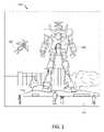
- FIG. 1illustrates a user's view of augmented reality (AR) through an AR device.
- ARaugmented reality
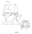
- FIG. 2illustrates an example of wearable display system.
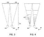
- FIG. 3illustrates a conventional display system for simulating three-dimensional imagery for a user.
- FIG. 4illustrates aspects of an approach for simulating three-dimensional imagery using multiple depth planes.
- FIGS. 5A-5Cillustrate relationships between radius of curvature and focal radius.
- FIG. 6illustrates an example of a waveguide stack for outputting image information to a user.
- FIG. 7illustrates an example of exit beams outputted by a waveguide.
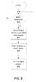
- FIG. 8illustrates a flowchart of a process for reducing current drain of the display system.
- an augmented reality scene 100is depicted.
- virtual realityor “augmented reality” experiences
- a virtual reality, or “VR”, scenariotypically involves presentation of digital or virtual image information without transparency to other actual real-world visual input
- an augmented reality, or “AR”scenario typically involves presentation of digital or virtual image information as an augmentation to visualization of the actual world around the user.
- FIG. 1A virtual reality, or “VR”, scenario typically involves presentation of digital or virtual image information without transparency to other actual real-world visual input; an augmented reality, or “AR”, scenario typically involves presentation of digital or virtual image information as an augmentation to visualization of the actual world around the user.
- FIG. 1shows an example of such a scene in which a user of an AR technology sees a real-world park-like setting 110 featuring people, trees, buildings in the background, and a concrete platform 120 .
- the user of the AR technologyalso perceives that he “sees” a robot statue 130 standing upon the real-world platform 120 , and a cartoon-like avatar character 140 flying by which seems to be a personification of a bumble bee, even though these elements 130 , 150 do not exist in the real world.
- the human visual perception systemis complex, it is challenging to produce a VR or AR technology that facilitates a comfortable, natural-feeling, rich presentation of virtual image elements amongst other virtual or real-world imagery elements.
- FIG. 2illustrates an example of wearable display system 200 .
- the display system 200includes a display 208 , and various mechanical and electronic modules and systems to support the functioning of that display 208 .
- the display 208may be coupled to a frame 212 , which is wearable by a display system user or viewer 201 and which is configured to position the display 208 in front of the eyes of the user 201 .
- the display 208may be considered eyewear in some embodiments.
- a speaker 216is coupled to the frame 212 and positioned adjacent the ear canal of the user 201 (in some embodiments, another speaker, not shown, is positioned adjacent the other ear canal of the user to provide for stereo/shapeable sound control).
- the display systemmay also include one or more microphones (not shown) or other devices to detect sound.
- the microphoneis configured to allow the user to provide inputs or commands to the system 200 (e.g., the selection of voice menu commands, natural language questions, etc.) and/or may allow audio communication with other persons (e.g., with other users of similar display systems).
- the display 208is operatively coupled, such as by a wired lead or wireless connectivity, to a local data processing module 224 which may be mounted in a variety of configurations, such as fixedly attached to the frame 212 , fixedly attached to a helmet or hat worn by the user, embedded in headphones, or otherwise removably attached to the user 201 (e.g., in a backpack-style configuration, in a belt-coupling style configuration).
- the local processing and data module 224may comprise a hardware processor or processing electronics or circuitry, as well as digital memory, such as non-volatile memory (e.g., flash memory or hard disk drives), both of which may be utilized to assist in the processing, caching, and storage of data.
- the datainclude data a) captured from sensors (which may be, e.g., operatively coupled to the frame 212 or otherwise attached to the user 201 ), such as image capture devices (such as cameras), microphones, inertial measurement units, accelerometers, compasses, GPS units, radio devices, and/or gyros; and/or b) acquired and/or processed using remote processing module 228 and/or remote data repository 232 , possibly for passage to the display 208 after such processing or retrieval.
- sensorswhich may be, e.g., operatively coupled to the frame 212 or otherwise attached to the user 201
- image capture devicessuch as cameras
- microphonessuch as cameras
- inertial measurement unitssuch as cameras
- accelerometerscompasses
- GPS unitsGPS units
- radio devicesradio devices
- the local processing and data module 224may be operatively coupled by communication links 236 , 240 , such as via a wired or wireless communication links, to the remote processing module 228 and remote data repository 232 such that these remote modules 228 , 232 are operatively coupled to each other and available as resources to the local processing and data module 224 .
- the local processing and data module 224may include one or more of the image capture devices, microphones, inertial measurement units, accelerometers, compasses, GPS units, radio devices, and/or gyros. In some other embodiments, one or more of these sensors may be attached to the frame 212 , or may be stand alone structures that communicate with the local processing and data module 224 by wired or wireless communication pathways.
- the remote processing module 228may comprise one or more processors or processing electronics or circuitry configured to analyze and process data and/or image information.
- the remote data repository 232may comprise a digital data storage facility, which may be available through the internet or other networking configuration in a “cloud” resource configuration.
- the remote data repository 232may include one or more remote servers, which provide information, e.g., information for generating augmented reality content, to the local processing and data module 224 and/or the remote processing module 228 .
- all datais stored and all computations are performed in the local processing and data module, allowing fully autonomous use from a remote module.
- FIG. 3illustrates a conventional display system for simulating three-dimensional imagery for a user.
- Two distinct images 306 , 308are outputted to the user.
- the images 306 , 308are spaced from the eyes 302 , 304 by a distance 310 along an optical or z-axis parallel to the line of sight of the viewer.
- the images 306 , 308are flat and the eyes 302 , 304 may focus on the images by assuming a single accommodated state.
- Such systemsrely on the human visual system to combine the images 306 , 308 to provide a perception of depth for the combined image.
- Such systemscan be uncomfortable for many viewers, however, since they, among other things, simply provide a different presentations of a scene, but with the eyes viewing all the image information at a single accommodated state, and work against the “accommodation-vergence reflex.” Display systems that provide a better match between accommodation and vergence may form more realistic and comfortable simulations of three-dimensional imagery.
- FIG. 4illustrates aspects of an approach for simulating three-dimensional imagery using multiple depth planes.
- Objects at various distances from eyes 302 , 304 on the z-axisare accommodated by the eyes 302 , 304 so that those objects are in focus.
- the eyes ( 302 and 304 )assume particular accommodated states to bring into focus objects at different distances along the z-axis. Consequently, a particular accommodated state may be said to be associated with a particular one of depth planes 402 , which has an associated focal distance, such that objects or parts of objects in a particular depth plane are in focus when the eye is in the accommodated state for that depth plane.
- three-dimensional imagerymay be simulated by providing different presentations of an image for each of the eyes 302 , 304 , and also by providing different presentations of the image corresponding to each of the depth planes. While shown as being separate for clarity of illustration, it will be appreciated that the fields of view of the eyes 302 , 304 may overlap, for example, as distance along the z-axis increases. In addition, while shown as flat for ease of illustration, it will be appreciated that the contours of a depth plane may be curved in physical space, such that all features in a depth plane are in focus with the eye in a particular accommodated state.
- FIGS. 5A-5Cillustrate relationships between distance and the divergence of light rays.
- the distance between the object and the eye 302is represented by, in order of decreasing distance, R 1 , R 2 , and R 3 .
- R 1 , R 2 , and R 3the distance between the object and the eye 302
- the light raysbecome more divergent as distance to the object decreases.
- the light raysbecome more collimated.
- the light field produced by a point(the object or a part of the object) has a spherical wavefront curvature, which is a function of how far away the point is from the eye of the user.
- the curvatureincreases with decreasing distance between the object and the eye 302 . Consequently, at different depth planes, the degree of divergence of light rays is also different, with the degree of divergence increasing with decreasing distance between depth planes and the viewer's eye 302 . While only a single eye 302 is illustrated for clarity of illustration in FIGS. 5A-5C and other figures herein, it will be appreciated that the discussions regarding eye 302 may be applied to both eyes 302 and 304 of a viewer.
- the human eyetypically can interpret a finite number of depth planes to provide depth perception. Consequently, a highly believable simulation of perceived depth may be achieved by providing, to the eye, different presentations of an image corresponding to each of these limited number of depth planes.
- the different presentationsmay be separately focused by the viewer's eyes, thereby helping to provide the user with depth cues based on the accommodation of the eye required to bring into focus different image features for the scene located on different depth plane and/or based on observing different image features on different depth planes being out of focus.
- FIG. 6illustrates an example of a waveguide stack for outputting image information to a user.
- a display system 600includes a stack of waveguides, or stacked waveguide assembly, 605 that may be utilized to provide three-dimensional perception to the eye/brain using a plurality of waveguides 620 , 622 , 624 , 626 , 628 .
- the display system 600is the system 200 of FIG. 2 , with FIG. 6 schematically showing some parts of that system 200 in greater detail.
- the waveguide assembly 605may be part of the display 208 of FIG. 2 .
- the waveguide assembly 1240may also include a plurality of features 630 , 632 , 634 , 636 between the waveguides.
- the features 630 , 632 , 634 , 636may be lenses.
- the waveguides 620 , 622 , 624 , 626 , 628 and/or the plurality of lenses 630 , 632 , 634 , 636may be configured to send image information to the eye with various levels of wavefront curvature or light ray divergence. Each waveguide level may be associated with a particular depth plane and may be configured to output image information corresponding to that depth plane.
- Image injection devices 640 , 642 , 644 , 646 , 648may function as a source of light for the waveguides and may be utilized to inject image information into the waveguides 620 , 622 , 624 , 626 , 628 , each of which may be configured, as described herein, to distribute incoming light across each respective waveguide, for output toward the eye 302 .
- the light sourcesthemselves act to switch depth planes by switching on or off the illumination for each depth plane, as desired.
- each of the input surfaces 670 , 672 , 674 , 676 , 678may be an edge of a corresponding waveguide, or may be part of a major surface of the corresponding waveguide (that is, one of the waveguide surfaces directly facing the world 610 or the viewer's eye 302 ).
- a single beam of light(e.g. a collimated beam) may be injected into each waveguide to output an entire field of cloned collimated beams that are directed toward the eye 302 at particular angles (and amounts of divergence) corresponding to the depth plane associated with a particular waveguide.
- a single one of the image injection devices 640 , 642 , 644 , 646 , 648may be associated with and inject light into a plurality (e.g., three) of the waveguides 620 , 622 , 624 , 626 , 628 .
- the image injection devices 640 , 642 , 644 , 646 , 648are discrete displays that each produce image information for injection into a corresponding waveguide 620 , 622 , 624 , 626 , 628 , respectively.
- the image injection devices 640 , 642 , 644 , 646 , 648comprise scanning fibers or scanning fiber display devices.
- the image injection devices 640 , 642 , 644 , 646 , 648are the output ends of a single multiplexed display which may, e.g., pipe image information via one or more optical conduits (such as fiber optic cables) to each of the image injection devices 640 , 642 , 644 , 646 , 648 .
- the image information provided by the image injection devices 640 , 642 , 644 , 646 , 648may include light of different wavelengths, or colors (e.g., different component colors).
- the light injected into the waveguides 620 , 622 , 624 , 626 , 628is provided by a light output module 614 , which may include a light source, such as backlight 614 b .
- the backlight 614 bmay comprise one or more emitters such as one or more light-emitting diodes (LEDs).
- the light from the backlight 614 bmay be modified by a light modulator 614 a , e.g., a spatial light modulator.
- the light modulator 614 amay be configured to change the perceived intensity of the light injected into the waveguides 620 , 622 , 624 , 626 , 628 .
- the light output modulemay include one or more light guides, light pipes or reflectors, which are configured to direct light from the emitter (e.g., by transmitting and/or reflecting the light) to the light modulator 614 a.
- a controller 612controls the operation of one or more of the stacked waveguide assembly 1240 , including operation of the image injection devices 640 , 642 , 644 , 646 , 648 , the light emitter 614 b , and/or the light modulator 614 a .
- the controller 612is part of the local data processing module 224 .
- the controller 612includes programming (e.g., instructions in a non-transitory medium) that regulates the timing and provision of image information to the waveguides 620 , 622 , 624 , 626 , 628 according to, e.g., any of the various schemes disclosed herein.
- the controller 612may be configured to control the operations and/or received input from one or more cameras or sensors (e.g., an inward-facing camera) that image an eye of a user, wherein the operation of the light emitter 614 b and/or light modulator 614 a may be based at least in part upon images of the eye and/or associated image data, such as the determination of when the eye is blinking or moving.
- the controllermay be a single integral device, or a distributed system connected by wired or wireless communication channels.
- the controller 612may be part of the processing modules or electronics 224 or 228 ( FIG. 2 ) and/or other processing electronics and circuitry in some embodiments.
- the waveguides 620 , 622 , 624 , 626 , 628 , 190may be configured to propagate light within each respective waveguide by total internal reflection (TIR).
- the waveguides 620 , 622 , 624 , 626 , 628may each be planar or have another shape (e.g., curved), with major top and bottom surfaces and edges extending between those major top and bottom surfaces.
- the waveguides 620 , 622 , 624 , 626 , 628may each include outcoupling optical elements 660 , 662 , 664 , 666 , 628 that are configured to extract light out of a waveguide by redirecting the light propagating within each respective waveguide, out of the waveguide to output image information to the eye 4 .
- Extracted lightmay also be referred to as outcoupled light and the outcoupling optical elements may also be referred to light extracting optical elements.
- An extracted beam of lightmay be outputted by the waveguide at locations at which the light propagating in the waveguide strikes a light extracting optical element.
- the outcoupling optical elements 660 , 662 , 664 , 666 , 628may, for example, be gratings, including diffractive optical features, as discussed further herein. While illustrated as disposed at the bottom major surfaces of the waveguides 620 , 622 , 624 , 626 , 628 for ease of description and drawing clarity, in some embodiments, the outcoupling optical elements 660 , 662 , 664 , 666 , 628 may be disposed at the top and/or bottom major surfaces, and/or may be disposed directly in the volume of the waveguides 620 , 622 , 624 , 626 , 628 , as discussed further herein.
- the outcoupling optical elements 660 , 662 , 664 , 666 , 628may be formed in a layer of material that is attached to a transparent substrate to form the waveguides 620 , 622 , 624 , 626 , 628 .
- the waveguides 620 , 622 , 624 , 626 , 628may be a monolithic piece of material and the outcoupling optical elements 660 , 662 , 664 , 666 , 628 may be formed on a surface and/or in the interior of that piece of material.
- each waveguide 620 , 622 , 624 , 626 , 628is configured to output light to form an image corresponding to a particular depth plane.
- the waveguide 620 nearest the eyemay be configured to deliver collimated light, as injected into such waveguide 620 , to the eye 302 .
- the collimated lightmay be representative of the optical infinity focal plane.
- the next waveguide up 622may be configured to send out collimated light which passes through the first lens 630 (e.g., a negative lens) before it can reach the eye 302 ; such first lens 630 may be configured to create a slight convex wavefront curvature so that the eye/brain interprets light coming from that next waveguide up 622 as coming from a first focal plane closer inward toward the eye 302 from optical infinity.
- first lens 630e.g., a negative lens
- the third up waveguide 624passes its output light through both the first 630 and second 632 lenses before reaching the eye 302 ; the combined optical power of the first 630 and second 632 lenses may be configured to create another incremental amount of wavefront curvature so that the eye/brain interprets light coming from the third waveguide 624 as coming from a second focal plane that is even closer inward toward the person from optical infinity than was light from the next waveguide up 622 .
- the other waveguide layers 626 , 628 and lenses 634 , 636are similarly configured, with the highest waveguide 628 in the stack sending its output through all of the lenses between it and the eye for an aggregate focal power representative of the closest focal plane to the person.
- a compensating lens layer 638may be disposed at the top of the stack to compensate for the aggregate power of the lens stack 630 , 632 , 634 , 636 below.
- Such a configurationprovides as many perceived focal planes as there are available waveguide/lens pairings.
- Both the outcoupling optical elements of the waveguides and the focusing aspects of the lensesmay be static (i.e., not dynamic or electro-active). In some alternative embodiments, either or both may be dynamic using electro-active features.
- two or more of the waveguides 620 , 622 , 624 , 626 , 628may have the same associated depth plane.
- multiple waveguides 620 , 622 , 624 , 626 , 628may be configured to output images set to the same depth plane, or multiple subsets of the waveguides 620 , 622 , 624 , 626 , 628 may be configured to output images set to the same plurality of depth planes, with one set for each depth plane. This can provide advantages for forming a tiled image to provide an expanded field of view at those depth planes.
- the outcoupling optical elements 660 , 662 , 664 , 666 , 628may be configured to both redirect light out of their respective waveguides and to output this light with the appropriate amount of divergence or collimation for a particular depth plane associated with the waveguide.
- waveguides having different associated depth planesmay have different configurations of outcoupling optical elements 660 , 662 , 664 , 666 , 628 , which output light with a different amount of divergence depending on the associated depth plane.
- the light extracting optical elements 660 , 662 , 664 , 666 , 628may be volumetric or surface features, which may be configured to output light at specific angles.
- the light extracting optical elements 660 , 662 , 664 , 666 , 628may be volume holograms, surface holograms, and/or diffraction gratings.
- the features 630 , 632 , 634 , 636may not be lenses; rather, they may simply be spacers (e.g., cladding layers and/or structures for forming air gaps).
- the outcoupling optical elements 660 , 662 , 664 , 666 , 628are diffractive features that form a diffraction pattern, or “diffractive optical element” (also referred to herein as a “DOE”).
- DOEdiffractive optical element
- the DOE'shave a sufficiently low diffraction efficiency so that only a portion of the light of the beam is deflected away toward the eye 302 with each intersection of the DOE, while the rest continues to move through a waveguide via total internal reflection.
- the light carrying the image informationis thus divided into a number of related exit beams that exit the waveguide at a multiplicity of locations and the result is a fairly uniform pattern of exit emission toward the eye 302 for this particular collimated beam bouncing around within a waveguide.
- one or more DOEsmay be switchable between “on” states in which they actively diffract, and “off” states in which they do not significantly diffract.
- a switchable DOEmay comprise a layer of polymer dispersed liquid crystal, in which microdroplets comprise a diffraction pattern in a host medium, and the refractive index of the microdroplets can be switched to substantially match the refractive index of the host material (in which case the pattern does not appreciably diffract incident light) or the microdroplet can be switched to an index that does not match that of the host medium (in which case the pattern actively diffracts incident light).
- FIG. 7shows an example of exit beams outputted by a waveguide.
- One waveguideis illustrated, but it will be appreciated that other waveguides in the waveguide assembly 605 may function similarly, where the waveguide assembly 605 includes multiple waveguides.
- Light 700is injected into the waveguide 620 at the input surface 670 of the waveguide 620 and propagates within the waveguide 620 by TIR. At points where the light 700 impinges on the DOE 660 , a portion of the light exits the waveguide as exit beams 702 .
- the exit beams 7are illustrated as substantially parallel but, as discussed herein, they may also be redirected to propagate to the eye 302 at an angle (e.g., forming divergent exit beams), depending on the depth plane associated with the waveguide 620 . It will be appreciated that substantially parallel exit beams may be indicative of a waveguide with outcoupling optical elements that outcouple light to form images that appear to be set on a depth plane at a large distance (e.g., optical infinity) from the eye 302 .
- waveguides or other sets of outcoupling optical elementsmay output an exit beam pattern that is more divergent, which would require the eye 302 to accommodate to a closer distance to bring it into focus on the retina and would be interpreted by the brain as light from a distance closer to the eye 302 than optical infinity.
- the display system 600 as discussed abovemay be powered by a battery. Current drain reduction or power reduction can be desirable in order to provide for more run time from the battery or to reduce heating of the device.
- current in the display system 200may be drawn to light the display of the display system 620 (e.g., using the backlight 614 b , image injection devices 640 , 642 , 644 , 646 , 648 such as possibly one or more scanning fibers or scanning fibers display devices, etc.).
- currentis employed to control the display (e.g., a graphics processor or driver of the controller 612 ).
- some current drain reduction or power reductioncan be achieved, for example, by dimming or turning off the display (e.g., dimming or turning off the display backlight), reducing the display update or refresh rate, or dimming or shutting off the display after a time-out period, based on lack of user interaction.
- dimming or turning off the displaye.g., dimming or turning off the display backlight
- reducing the display update or refresh ratee.g., dimming or turning off the display backlight
- dimming or shutting off the display after a time-out periodbased on lack of user interaction.
- a cameramay be used to track eye movement.
- the display system 600may comprise an inward facing camera 616 directed inward to the face of the user, and in particular, toward the eye of the user (e.g., the eye 302 ). In some cases, this eye tracking may be done, for example, in order to adjust the view being displayed by the display system 600 .
- the camera 616may be used to capture images of the eye 302 from which a state or position of the eye pupil or iris can be tracked. The state or position of the eye pupil or iris may be used to determine where the user of the device is looking, allowing for the display to be adjusted accordingly.
- eye trackingcan be used to determine if the user's eye is in a state where the user is temporarily unable to see. For example, the user may not be able to see when the user is blinking. In addition, the user may not be able to see when the user's eyes are undergoing a saccade (e.g., a rapid movement of the eyes between fixation points).
- a saccadee.g., a rapid movement of the eyes between fixation points.
- the eye tracking camera or inward facing cameracan be used to determine if the user is blinking by determining if the pupil or iris of the user is partially or fully blocked from view.
- the cameramay track the iris of the user's eye as a dark circle within a background (e.g., the eye white of the user).
- the cameramay track the pupil of the user as a darker circle within the iris.
- the controller 612may “graphically” detect the blink in response to the circle pattern corresponding to the user's iris or pupil being partially or totally missing.
- how much of the circle pattern is visiblemay be compared against a threshold value, wherein the user is determined to be blinking if the amount of visible (e.g., circle) pattern does not meet the threshold value.
- the threshold valuemay be preconfigured based upon user trials.
- the controller 612may detect whether the user is blinking based upon an amount of contrast calculated from the view of the camera 616 . For example, a determination may be made as to whether the contrast meets a threshold value. In some embodiments, when the user's eye is open and the iris or pupil of the user is visible, there may be a high amount of contrast in the images reflected back (e.g., from the eye or combinations of the eye and eyelid) and captured by the camera. On the other hand, when the user's eye is closed (e.g., the user's eyelid covers the eye), the amount of contrast may be much lower compared to when the user's eye is open (e.g., at least partially open). As such, the controller 612 may detect a blink when the contrast is lower than the threshold value.
- the controller 612may generate an “error” state if the iris or pupil of the user is unable to be detected, which may also serve as a blink detection.
- the controller 612may detect a saccade by the user. When the user's eyes are in a state of saccade, the user may not perceive any visual information despite the user's eyes being open. In some embodiments, the controller 612 may detect a saccade by using the inward facing camera 616 to track a location of the user's iris or pupil (e.g., as a dark circle, as discussed above). If movement of the user's iris or pupil above a certain rate is detected, then the user may be considered to be in a saccade state.
- a time period of a blink or saccademay be a predetermined period of time.
- the predetermined period of timemay be determined based upon empirical data from user studies.
- a time period for a blink or saccademay be measured by one or more sensors of the display system 600 (e.g., the inward facing camera 616 ) based upon eye open/closed criteria or eye movement criteria as discussed above. If the eye is closed or experiencing saccades for a period of time, the system may be set to a lower energy state to conserve power.
- any type of hardware that can be used to detect a state of the user's eyemay be used, such as other types of sensor systems.
- it may be desirable to utilize hardware already integrated with display system 600e.g., hardware designed to serve other purposes in the display system 600 ), in order to reduce power consumption that would be consumed by the addition of new hardware.
- the camera or other type of sensor systemis not limited to using visible light and may employ infrared (IR) light.
- the display system 600may reduce its current or power drain during the period when the user is unable to see (e.g., due to a blink or saccade). For example, current drain or power usage of the display can be reduced by employing one or more current drain or power reduction techniques, which may include dimming or turning off a light source for the display (e.g., a backlight) associated with the display.
- the light source (e.g., backlight) 614 b of the display system 600may be dimmed or turned off.
- current drain or power usagemay be reduced by dimming or turning off one or more active pixels of the display.
- Other types of display components or displaysmay be turned off, dimmed or set to a lower power consumption mode when the eye cannot see (e.g., during a blink or saccades).
- a graphics driver or processor or processing electronics associated with the display“skips” a number of frames or waits for a designated period of time where the graphics driver is in a state that causes less power to be consumed than if providing new images or refreshing images.
- the graphics drivercan cause the graphics processor to suspend refreshing a displayed image, or reduce a refresh rate of the display, thus consuming less power in comparison to normal operation.
- the number of frames or period of time during which current drain is reducedmay be configured to correspond to a length of the blink or saccade. The time period for a blink, for example, is typically between 100 to 400 mSec.
- the controller 612may dim the backlight 614 b as well as cause the graphics drive to skip a designated number of frames. In other embodiments, the controller 612 may cause the graphics driver to skip a designated number of frames without dimming the backlight 614 b , or vice versa.
- FIG. 8illustrates a flowchart of an example process for reducing current draining or power usage, in accordance with some embodiments. Any portion of this flowchart may be executed by electronics such as processing electronics or circuitry.
- a determinationis made as to whether a state when a user of the display system is unable to see is detected (e.g., a blink or saccade by the user). In some embodiments, this may be done using an eye tracking or inward facing camera or other sensor or sensor system that determines whether the pupil or iris of the user is blocked from view or is experiencing rapid movement. If a blink or saccade is detected, the process may proceed to block 804 . Otherwise, the process may continue to monitor the eye, for example, to detect for a blink or saccade by the user of the display system.
- a light source associated with the displayis dimmed or turned off.
- the light sourcemay be configured to enter a low power mode or be disabled.
- the light sourcemay comprise the backlight 614 b .
- the light sourcemay comprise a plurality of active pixels of the display (e.g., of an OLED display). Other light sources and display configurations are possible.
- a graphics driver associated with the display systemmay reduce an amount of power consumed. For example, the graphics driver may skip X number of frames or wait for a period of time Y, wherein X and Y are determined based upon a period of a blink (e.g., between 100 and 400 mSec) or saccade. In some embodiments, the graphics driver may reduce a refresh rate of the display.
- the light source associated with the displaye.g., the backlight 614 b , active pixels of the display, and/or the like
- the display systemresumes normal operation. It is understood that the process illustrated in this flowchart is an example, and that steps may be excluded, added, and/or reordered.
- FIG. 8illustrates both dimming/turning off a light source associated with the display (blocks 804 , 808 ) and reducing a power consumption of a graphics driver or processor (block 806 )
- the display system 600may perform any combination of current drain or power reduction techniques.
- the display system 600may perform only dimming/turning off the light source of the display, only reducing a power consumption of the graphics driver or processor (e.g., skipping frames, reducing a refresh rate, and/or the like), or both.
- Power conservationcan also come from other components. For example, setting the spatial light modulator or one or more scanning fibers or scanning fiber display devices to a lower power state can also reduce power consumption.
- the average personblinks about once every 2 to 10 seconds, for a period of 100 to 400 msec.
- the eyesare closed for about 1% of the time.
- the eyeswill be closed for 2% to 5% of the time. Therefore a reduction of a few percent can possibly be achieved in the current drain associated with lighting the display using a light source (e.g., a backlight or active pixels) and/or the graphics driver/processor.
- a light sourcee.g., a backlight or active pixels
- the graphics driver/processore.g., a graphics driver/processor.
- the inventionincludes methods that may be performed using the subject devices.
- the methodsmay comprise the act of providing such a suitable device. Such provision may be performed by the user.
- the “providing” actmerely requires the user obtain, access, approach, position, set-up, activate, power-up or otherwise act to provide the requisite device in the subject method.
- Methods recited hereinmay be carried out in any order of the recited events that is logically possible, as well as in the recited order of events.
- any optional feature of the inventive variations describedmay be set forth and claimed independently, or in combination with any one or more of the features described herein.
- Reference to a singular itemincludes the possibility that there are plural of the same items present. More specifically, as used herein and in claims associated hereto, the singular forms “a,” “an,” “said,” and “the” include plural referents unless the specifically stated otherwise.
- use of the articlesallow for “at least one” of the subject item in the description above as well as claims associated with this disclosure. It is further noted that such claims may be drafted to exclude any optional element. As such, this statement is intended to serve as antecedent basis for use of such exclusive terminology as “solely,” “only” and the like in connection with the recitation of claim elements, or use of a “negative” limitation.
Landscapes
- Engineering & Computer Science (AREA)
- Theoretical Computer Science (AREA)
- General Engineering & Computer Science (AREA)
- Physics & Mathematics (AREA)
- General Physics & Mathematics (AREA)
- Human Computer Interaction (AREA)
- Computer Hardware Design (AREA)
- Crystallography & Structural Chemistry (AREA)
- Chemical & Material Sciences (AREA)
- Control Of Indicators Other Than Cathode Ray Tubes (AREA)
- Transforming Electric Information Into Light Information (AREA)
- Controls And Circuits For Display Device (AREA)
- Liquid Crystal Display Device Control (AREA)
- Testing, Inspecting, Measuring Of Stereoscopic Televisions And Televisions (AREA)
- Control Of El Displays (AREA)
- Electronic Switches (AREA)
- Mechanical Optical Scanning Systems (AREA)
- Devices For Indicating Variable Information By Combining Individual Elements (AREA)
Abstract
Description
- an inward-facing sensor;
- a display; and
- processing electronics in communication with the inward-facing sensor and the display, the processing electronics configured to:
- detect a change in a user's eye status using the inward facing sensor, and
- reduce a current drain of the display system based on when the change in the user's eye status is detected.
- detecting a change in a user's eye status using an inward facing sensor, and
- reducing a current drain of the display system based on when the change in the user's eye status is detected.
- an inward-facing camera;
- a display; and
- hardware processing electronics in communication with the inward-facing camera and the display, the hardware processing electronics programmed to:
- using the camera determine when a user of the display is blinking; and
- in response to a determination that the user is blinking, reducing a current drain of the display system.
- using an inward-facing camera to determine when a user of the display system is blinking; and
- in response to a determination that the user is blinking, reducing a current drain of the display.
Claims (44)
Priority Applications (6)
| Application Number | Priority Date | Filing Date | Title |
|---|---|---|---|
| US15/448,402US11320900B2 (en) | 2016-03-04 | 2017-03-02 | Current drain reduction in AR/VR display systems |
| US16/544,707US10649527B2 (en) | 2016-03-04 | 2019-08-19 | Current drain reduction in AR/VR display systems |
| US15/930,386US11402898B2 (en) | 2016-03-04 | 2020-05-12 | Current drain reduction in AR/VR display systems |
| US17/734,965US11775062B2 (en) | 2016-03-04 | 2022-05-02 | Current drain reduction in AR/VR display systems |
| US18/338,235US12229337B2 (en) | 2016-03-04 | 2023-06-20 | Current drain reduction in AR/VR display systems |
| US19/022,748US20250155973A1 (en) | 2016-03-04 | 2025-01-15 | Current drain reduction in ar/vr display systems |
Applications Claiming Priority (2)
| Application Number | Priority Date | Filing Date | Title |
|---|---|---|---|
| US201662304098P | 2016-03-04 | 2016-03-04 | |
| US15/448,402US11320900B2 (en) | 2016-03-04 | 2017-03-02 | Current drain reduction in AR/VR display systems |
Related Parent Applications (1)
| Application Number | Title | Priority Date | Filing Date |
|---|---|---|---|
| US15/448,402ContinuationUS11320900B2 (en) | 2016-03-04 | 2017-03-02 | Current drain reduction in AR/VR display systems |
Related Child Applications (4)
| Application Number | Title | Priority Date | Filing Date |
|---|---|---|---|
| US15/448,402ContinuationUS11320900B2 (en) | 2016-03-04 | 2017-03-02 | Current drain reduction in AR/VR display systems |
| US16/544,707ContinuationUS10649527B2 (en) | 2016-03-04 | 2019-08-19 | Current drain reduction in AR/VR display systems |
| US15/930,386ContinuationUS11402898B2 (en) | 2016-03-04 | 2020-05-12 | Current drain reduction in AR/VR display systems |
| US17/734,965ContinuationUS11775062B2 (en) | 2016-03-04 | 2022-05-02 | Current drain reduction in AR/VR display systems |
Publications (2)
| Publication Number | Publication Date |
|---|---|
| US20170255259A1 US20170255259A1 (en) | 2017-09-07 |
| US11320900B2true US11320900B2 (en) | 2022-05-03 |
Family
ID=59722695
Family Applications (6)
| Application Number | Title | Priority Date | Filing Date |
|---|---|---|---|
| US15/448,402ActiveUS11320900B2 (en) | 2016-03-04 | 2017-03-02 | Current drain reduction in AR/VR display systems |
| US16/544,707ActiveUS10649527B2 (en) | 2016-03-04 | 2019-08-19 | Current drain reduction in AR/VR display systems |
| US15/930,386ActiveUS11402898B2 (en) | 2016-03-04 | 2020-05-12 | Current drain reduction in AR/VR display systems |
| US17/734,965ActiveUS11775062B2 (en) | 2016-03-04 | 2022-05-02 | Current drain reduction in AR/VR display systems |
| US18/338,235ActiveUS12229337B2 (en) | 2016-03-04 | 2023-06-20 | Current drain reduction in AR/VR display systems |
| US19/022,748PendingUS20250155973A1 (en) | 2016-03-04 | 2025-01-15 | Current drain reduction in ar/vr display systems |
Family Applications After (5)
| Application Number | Title | Priority Date | Filing Date |
|---|---|---|---|
| US16/544,707ActiveUS10649527B2 (en) | 2016-03-04 | 2019-08-19 | Current drain reduction in AR/VR display systems |
| US15/930,386ActiveUS11402898B2 (en) | 2016-03-04 | 2020-05-12 | Current drain reduction in AR/VR display systems |
| US17/734,965ActiveUS11775062B2 (en) | 2016-03-04 | 2022-05-02 | Current drain reduction in AR/VR display systems |
| US18/338,235ActiveUS12229337B2 (en) | 2016-03-04 | 2023-06-20 | Current drain reduction in AR/VR display systems |
| US19/022,748PendingUS20250155973A1 (en) | 2016-03-04 | 2025-01-15 | Current drain reduction in ar/vr display systems |
Country Status (10)
| Country | Link |
|---|---|
| US (6) | US11320900B2 (en) |
| EP (1) | EP3424038A4 (en) |
| JP (6) | JP7190903B2 (en) |
| KR (3) | KR20230109789A (en) |
| CN (2) | CN109074785B (en) |
| AU (2) | AU2017225977C1 (en) |
| CA (1) | CA3016032C (en) |
| IL (3) | IL307287A (en) |
| NZ (2) | NZ756561A (en) |
| WO (1) | WO2017151974A1 (en) |
Cited By (3)
| Publication number | Priority date | Publication date | Assignee | Title |
|---|---|---|---|---|
| US11775062B2 (en) | 2016-03-04 | 2023-10-03 | Magic Leap, Inc. | Current drain reduction in AR/VR display systems |
| US11966059B2 (en) | 2016-03-25 | 2024-04-23 | Magic Leap, Inc. | Virtual and augmented reality systems and methods |
| US12205545B2 (en) | 2022-09-13 | 2025-01-21 | Samsung Electronics Co., Ltd. | Electronic device and method for driving display thereof |
Families Citing this family (18)
| Publication number | Priority date | Publication date | Assignee | Title |
|---|---|---|---|---|
| US10372205B2 (en)* | 2016-03-31 | 2019-08-06 | Sony Interactive Entertainment Inc. | Reducing rendering computation and power consumption by detecting saccades and blinks |
| US10401952B2 (en) | 2016-03-31 | 2019-09-03 | Sony Interactive Entertainment Inc. | Reducing rendering computation and power consumption by detecting saccades and blinks |
| US10192528B2 (en) | 2016-03-31 | 2019-01-29 | Sony Interactive Entertainment Inc. | Real-time user adaptive foveated rendering |
| GB2566013B (en)* | 2017-08-24 | 2022-12-07 | Displaylink Uk Ltd | Compressing image data for transmission to a display |
| GB2607455B (en)* | 2017-08-24 | 2023-02-15 | Displaylink Uk Ltd | Compressing image data for transmission to a display |
| WO2019246044A1 (en) | 2018-06-18 | 2019-12-26 | Magic Leap, Inc. | Head-mounted display systems with power saving functionality |
| JP7378431B2 (en) | 2018-06-18 | 2023-11-13 | マジック リープ, インコーポレイテッド | Augmented reality display with frame modulation functionality |
| US10802585B2 (en) | 2018-07-12 | 2020-10-13 | Apple Inc. | Electronic devices with display operation based on eye activity |
| US11966055B2 (en) | 2018-07-19 | 2024-04-23 | Magic Leap, Inc. | Content interaction driven by eye metrics |
| US20200073465A1 (en)* | 2018-08-30 | 2020-03-05 | Qualcomm Incorporated | Load reduction in a visual rendering system |
| JP7431244B2 (en) | 2019-01-18 | 2024-02-14 | マジック リープ, インコーポレイテッド | Virtual, augmented, and mixed reality systems and methods |
| CN112445315B (en)* | 2019-08-28 | 2024-11-05 | 北京小米移动软件有限公司 | Screen refresh frame rate control method, device and storage medium |
| CN110658904A (en)* | 2019-09-19 | 2020-01-07 | Oppo广东移动通信有限公司 | Method, device, terminal and storage medium for controlling terminal current |
| US11568242B2 (en) | 2019-12-05 | 2023-01-31 | International Business Machines Corporation | Optimization framework for real-time rendering of media using machine learning techniques |
| US11960345B2 (en) | 2021-05-25 | 2024-04-16 | Samsung Electronics Co., Ltd. | System and method for controlling operational modes for XR devices for performance optimization |
| SE545387C2 (en)* | 2021-06-30 | 2023-07-25 | Tobii Ab | Method, computer program product, control unit and head-mounted display for conserving energy in an eye tracking system |
| US12405653B2 (en)* | 2022-09-23 | 2025-09-02 | Qualcomm Incorporated | Providing runtime power profile tuning based on eye state in processor-based extended reality (XR) devices |
| KR102824355B1 (en) | 2022-11-21 | 2025-06-24 | 가온그룹 주식회사 | control method for power saving of XR devices by use of local dimming |
Citations (91)
| Publication number | Priority date | Publication date | Assignee | Title |
|---|---|---|---|---|
| JPH08271953A (en) | 1995-03-30 | 1996-10-18 | Olympus Optical Co Ltd | Finder device |
| EP0849959A2 (en) | 1996-12-18 | 1998-06-24 | Toyota Jidosha Kabushiki Kaisha | Apparatus and method for displaying stereoscopic images |
| JPH11249064A (en) | 1998-03-04 | 1999-09-17 | Omron Corp | Head mounted display device |
| US20040130680A1 (en) | 2002-03-13 | 2004-07-08 | Samuel Zhou | Systems and methods for digitally re-mastering or otherwise modifying motion pictures or other image sequences data |
| US6850221B1 (en) | 1995-09-05 | 2005-02-01 | Interlink Electronics, Inc. | Trigger operated electronic device |
| USD514570S1 (en) | 2004-06-24 | 2006-02-07 | Microsoft Corporation | Region of a fingerprint scanning device with an illuminated ring |
| US20060028436A1 (en) | 1992-03-05 | 2006-02-09 | Armstrong Brad A | Image controller |
| JP2006059147A (en) | 2004-08-20 | 2006-03-02 | Kiyomi Nakamura | Computer input method and device |
| US20060140166A1 (en) | 2004-12-27 | 2006-06-29 | Microsoft Corporation | Reducing power consumption of a wireless device |
| US20070081123A1 (en) | 2005-10-07 | 2007-04-12 | Lewis Scott W | Digital eyewear |
| JP2009267733A (en) | 2008-04-24 | 2009-11-12 | Sharp Corp | Imaging apparatus and imaging control method |
| US20100118019A1 (en) | 2008-11-12 | 2010-05-13 | International Business Machines Corporation | Dynamically Managing Power Consumption Of A Computer With Graphics Adapter Configurations |
| JP2010187132A (en) | 2009-02-10 | 2010-08-26 | Brother Ind Ltd | Head mounted display |
| US20110075257A1 (en) | 2009-09-14 | 2011-03-31 | The Arizona Board Of Regents On Behalf Of The University Of Arizona | 3-Dimensional electro-optical see-through displays |
| US20110085700A1 (en) | 2009-07-13 | 2011-04-14 | Lee Hans C | Systems and Methods for Generating Bio-Sensory Metrics |
| US20110106025A1 (en) | 2009-10-29 | 2011-05-05 | Hall Gary S | Ophthalmic fluid pump |
| US20110182469A1 (en) | 2010-01-28 | 2011-07-28 | Nec Laboratories America, Inc. | 3d convolutional neural networks for automatic human action recognition |
| US20110242661A1 (en) | 2008-12-12 | 2011-10-06 | Bae Systems Plc | waveguides |
| JP2012022150A (en) | 2010-07-14 | 2012-02-02 | Nikon Corp | Display device and display method |
| US20120127062A1 (en) | 2010-11-18 | 2012-05-24 | Avi Bar-Zeev | Automatic focus improvement for augmented reality displays |
| US20120162549A1 (en) | 2010-12-24 | 2012-06-28 | Chunyu Gao | Ergonomic Head Mounted Display Device And Optical System |
| US20120242570A1 (en) | 2011-03-24 | 2012-09-27 | Seiko Epson Corporation | Device, head mounted display, control method of device and control method of head mounted display |
| JP2012203127A (en) | 2011-03-24 | 2012-10-22 | Seiko Epson Corp | Head mounted display, method for controlling head mounted display and computer program for controlling head mounted display |
| US20130082922A1 (en) | 2011-09-29 | 2013-04-04 | Samuel A. Miller | Tactile glove for human-computer interaction |
| US8437513B1 (en) | 2012-08-10 | 2013-05-07 | EyeVerify LLC | Spoof detection for biometric authentication |
| US20130117377A1 (en) | 2011-10-28 | 2013-05-09 | Samuel A. Miller | System and Method for Augmented and Virtual Reality |
| US20130125027A1 (en) | 2011-05-06 | 2013-05-16 | Magic Leap, Inc. | Massive simultaneous remote digital presence world |
| US20130135196A1 (en)* | 2011-11-29 | 2013-05-30 | Samsung Electronics Co., Ltd. | Method for operating user functions based on eye tracking and mobile device adapted thereto |
| US20130208234A1 (en) | 2005-10-07 | 2013-08-15 | Percept Technologies Inc. | Enhanced optical and perceptual digital eyewear |
| JP2013162407A (en) | 2012-02-07 | 2013-08-19 | Sharp Corp | Image display device |
| US20130242262A1 (en) | 2005-10-07 | 2013-09-19 | Percept Technologies Inc. | Enhanced optical and perceptual digital eyewear |
| US20130257709A1 (en)* | 2012-04-02 | 2013-10-03 | Google Inc. | Proximity Sensing for Wink Detection |
| US20130300652A1 (en) | 2011-11-30 | 2013-11-14 | Google, Inc. | Unlocking a Screen Using Eye Tracking Information |
| US20130314793A1 (en) | 2012-05-22 | 2013-11-28 | Steven John Robbins | Waveguide optics focus elements |
| US20140071539A1 (en) | 2012-09-11 | 2014-03-13 | Magic Leap, Inc. | Ergonomic head mounted display device and optical system |
| US20140145914A1 (en) | 2012-11-29 | 2014-05-29 | Stephen Latta | Head-mounted display resource management |
| US20140177023A1 (en) | 2012-04-05 | 2014-06-26 | Augmented Vision Inc. | Apparatus for optical see-through head mounted display with mutual occlusion and opaqueness control capability |
| US20140247210A1 (en) | 2013-03-01 | 2014-09-04 | Tobii Technology Ab | Zonal gaze driven interaction |
| US20140267420A1 (en) | 2013-03-15 | 2014-09-18 | Magic Leap, Inc. | Display system and method |
| US20140306866A1 (en) | 2013-03-11 | 2014-10-16 | Magic Leap, Inc. | System and method for augmented and virtual reality |
| US20140380249A1 (en) | 2013-06-25 | 2014-12-25 | Apple Inc. | Visual recognition of gestures |
| US20150016777A1 (en) | 2012-06-11 | 2015-01-15 | Magic Leap, Inc. | Planar waveguide apparatus with diffraction element(s) and system employing same |
| US8950867B2 (en) | 2011-11-23 | 2015-02-10 | Magic Leap, Inc. | Three dimensional virtual and augmented reality display system |
| US20150061999A1 (en)* | 2013-08-28 | 2015-03-05 | Lg Electronics Inc. | Wearable display and method of controlling therefor |
| US8976110B2 (en) | 2011-10-27 | 2015-03-10 | Tobii Technology Ab | Power management in an eye-tracking system |
| US20150103306A1 (en) | 2013-10-16 | 2015-04-16 | Magic Leap, Inc. | Virtual or augmented reality headsets having adjustable interpupillary distance |
| JP2015081313A (en) | 2013-10-23 | 2015-04-27 | 株式会社光波 | Single crystal phosphor and light emitting device |
| WO2015081313A2 (en) | 2013-11-27 | 2015-06-04 | Magic Leap, Inc. | Virtual and augmented reality systems and methods |
| US20150178939A1 (en) | 2013-11-27 | 2015-06-25 | Magic Leap, Inc. | Virtual and augmented reality systems and methods |
| US20150222883A1 (en) | 2014-01-31 | 2015-08-06 | Magic Leap, Inc. | Multi-focal display system and method |
| US20150222884A1 (en) | 2014-01-31 | 2015-08-06 | Magic Leap, Inc. | Multi-focal display system and method |
| US20150241967A1 (en) | 2014-02-25 | 2015-08-27 | EyeVerify Inc. | Eye Gaze Tracking |
| KR20150098162A (en) | 2014-02-19 | 2015-08-27 | 삼성전자주식회사 | Method and apparatus for controlling operation associated with multimedia data |
| KR20150099430A (en) | 2014-02-21 | 2015-08-31 | 삼성전자주식회사 | Electronic device |
| US20150248170A1 (en) | 2013-07-12 | 2015-09-03 | Magic Leap, Inc. | Method and system for generating a virtual user interface related to a totem |
| WO2015134740A1 (en) | 2014-03-05 | 2015-09-11 | Arizona Board Of Regents On Behalf Of The University Of Arizona | Wearable 3d augmented reality display with variable focus and/or object recognition |
| US20150268415A1 (en) | 2013-01-15 | 2015-09-24 | Magic Leap, Inc. | Ultra-high resolution scanning fiber display |
| US20150301599A1 (en) | 2014-04-18 | 2015-10-22 | Magic Leap, Inc. | Eye tracking systems and method for augmented or virtual reality |
| US20150326570A1 (en) | 2014-05-09 | 2015-11-12 | Eyefluence, Inc. | Systems and methods for discerning eye signals and continuous biometric identification |
| JP2015205114A (en) | 2014-04-23 | 2015-11-19 | アルプス電気株式会社 | Eyeglass-type electronic equipment |
| WO2015184412A1 (en) | 2014-05-30 | 2015-12-03 | Magic Leap, Inc. | Methods and system for creating focal planes in virtual and augmented reality |
| US20150346490A1 (en) | 2014-05-30 | 2015-12-03 | Magic Leap, Inc. | Methods and systems for generating virtual content display with a virtual or augmented reality apparatus |
| US20150346495A1 (en) | 2014-05-30 | 2015-12-03 | Magic Leap, Inc. | Methods and system for creating focal planes in virtual and augmented reality |
| US9207760B1 (en) | 2012-09-28 | 2015-12-08 | Google Inc. | Input detection |
| US20160011419A1 (en) | 2010-12-24 | 2016-01-14 | Magic Leap, Inc. | Methods and systems for displaying stereoscopy with a freeform optical system with addressable focus for virtual and augmented reality |
| US20160025971A1 (en) | 2014-07-25 | 2016-01-28 | William M. Crow | Eyelid movement as user input |
| US20160026253A1 (en) | 2014-03-11 | 2016-01-28 | Magic Leap, Inc. | Methods and systems for creating virtual and augmented reality |
| US20160048220A1 (en) | 2014-08-14 | 2016-02-18 | Qualcomm Incorporated | Management for wearable display |
| US20160085300A1 (en) | 2014-09-24 | 2016-03-24 | Steven Robbins | Waveguide eye tracking employing switchable diffraction gratings |
| USD752529S1 (en) | 2014-06-09 | 2016-03-29 | Comcast Cable Communications, Llc | Electronic housing with illuminated region |
| US9310559B2 (en) | 2012-06-11 | 2016-04-12 | Magic Leap, Inc. | Multiple depth plane three-dimensional display using a wave guide reflector array projector |
| US20160109709A1 (en)* | 2014-01-21 | 2016-04-21 | Osterhout Group, Inc. | See-through computer display systems |
| US20160131905A1 (en) | 2014-11-07 | 2016-05-12 | Kabushiki Kaisha Toshiba | Electronic apparatus, method and storage medium |
| US20160133201A1 (en) | 2014-11-07 | 2016-05-12 | Osterhout Group, Inc. | Power management for head worn computing |
| USD758367S1 (en) | 2015-05-14 | 2016-06-07 | Magic Leap, Inc. | Virtual reality headset |
| USD759657S1 (en) | 2014-05-19 | 2016-06-21 | Microsoft Corporation | Connector with illumination region |
| US20160270656A1 (en) | 2015-03-16 | 2016-09-22 | Magic Leap, Inc. | Methods and systems for diagnosing and treating health ailments |
| US9489044B2 (en) | 2014-11-07 | 2016-11-08 | Eye Labs, LLC | Visual stabilization system for head-mounted displays |
| EP3109689A1 (en) | 2015-06-22 | 2016-12-28 | Nokia Technologies Oy | Transition from a display power mode to a different display power mode |
| JP2017058853A (en) | 2015-09-15 | 2017-03-23 | 株式会社コーエーテクモゲームス | Information processing apparatus, operation control method, and operation control program |
| US9606622B1 (en) | 2014-06-26 | 2017-03-28 | Audible, Inc. | Gaze-based modification to content presentation |
| USD794288S1 (en) | 2016-03-11 | 2017-08-15 | Nike, Inc. | Shoe with illuminable sole light sequence |
| US20170237974A1 (en) | 2014-03-14 | 2017-08-17 | Magic Leap, Inc. | Multi-depth plane display system with reduced switching between depth planes |
| WO2017139667A1 (en) | 2016-02-11 | 2017-08-17 | Magic Leap, Inc. | Multi-depth plane display system with reduced switching between depth planes |
| WO2017151974A1 (en) | 2016-03-04 | 2017-09-08 | Magic Leap, Inc. | Current drain reduction in ar/vr display systems |
| US20170276948A1 (en) | 2016-03-25 | 2017-09-28 | Magic Leap, Inc. | Virtual and augmented reality systems and methods |
| US20170293356A1 (en) | 2016-04-08 | 2017-10-12 | Vizzario, Inc. | Methods and Systems for Obtaining, Analyzing, and Generating Vision Performance Data and Modifying Media Based on the Vision Performance Data |
| USD805734S1 (en) | 2016-03-04 | 2017-12-26 | Nike, Inc. | Shirt |
| US20180039083A1 (en) | 2016-08-02 | 2018-02-08 | Magic Leap, Inc. | Fixed-distance virtual and augmented reality systems and methods |
| WO2020042654A1 (en) | 2018-08-28 | 2020-03-05 | 武汉华星光电技术有限公司 | Method for reducing power consumption of display panel, and low-power-consumption display apparatus |
| US20210181514A1 (en) | 2018-07-19 | 2021-06-17 | Magic Leap, Inc. | Content interaction driven by eye metrics |
Family Cites Families (13)
| Publication number | Priority date | Publication date | Assignee | Title |
|---|---|---|---|---|
| JP3563459B2 (en)* | 1994-10-31 | 2004-09-08 | 大正製薬株式会社 | Blink detection system |
| JPH09105853A (en) | 1995-10-06 | 1997-04-22 | Canon Inc | Optical device and photographing device |
| JP4129972B2 (en) | 2002-02-18 | 2008-08-06 | オリンパス株式会社 | Decentered optical system |
| RU2493613C2 (en)* | 2008-08-22 | 2013-09-20 | Сони Корпорейшн | Image display device and driving method |
| JP5308305B2 (en) | 2009-10-20 | 2013-10-09 | 株式会社トーメーコーポレーション | Retinal potential measuring device |
| US9128281B2 (en) | 2010-09-14 | 2015-09-08 | Microsoft Technology Licensing, Llc | Eyepiece with uniformly illuminated reflective display |
| US9766381B2 (en) | 2010-03-12 | 2017-09-19 | Nokia Technologies Oy | Light-guiding structures |
| JP2012109810A (en)* | 2010-11-17 | 2012-06-07 | Panasonic Corp | Display device, display control method, mobile phone, and semiconductor device |
| US20130300634A1 (en) | 2012-05-09 | 2013-11-14 | Nokia Corporation | Method and apparatus for determining representations of displayed information based on focus distance |
| CN110022472B (en) | 2012-10-18 | 2022-07-26 | 亚利桑那大学评议会 | Stereoscopic display with addressable focus cues |
| JP6364790B2 (en)* | 2014-01-30 | 2018-08-01 | 株式会社リコー | pointing device |
| JP2014222909A (en) | 2014-07-02 | 2014-11-27 | パナソニック株式会社 | Display device, display control method, and semiconductor device |
| JP6573755B2 (en) | 2014-07-10 | 2019-09-11 | 富士通株式会社 | Display control method, information processing program, and information processing apparatus |
- 2017
- 2017-03-02AUAU2017225977Apatent/AU2017225977C1/enactiveActive
- 2017-03-02NZNZ756561Apatent/NZ756561A/enunknown
- 2017-03-02ILIL307287Apatent/IL307287A/enunknown
- 2017-03-02JPJP2018545667Apatent/JP7190903B2/enactiveActive
- 2017-03-02EPEP17760851.0Apatent/EP3424038A4/enactivePending
- 2017-03-02WOPCT/US2017/020522patent/WO2017151974A1/ennot_activeCeased
- 2017-03-02CACA3016032Apatent/CA3016032C/enactiveActive
- 2017-03-02CNCN201780027169.8Apatent/CN109074785B/enactiveActive
- 2017-03-02KRKR1020237023562Apatent/KR20230109789A/enactivePending
- 2017-03-02CNCN202210361819.5Apatent/CN114690881A/enactivePending
- 2017-03-02NZNZ745738Apatent/NZ745738A/enunknown
- 2017-03-02KRKR1020227006658Apatent/KR102556320B1/enactiveActive
- 2017-03-02ILIL291915Apatent/IL291915B2/enunknown
- 2017-03-02USUS15/448,402patent/US11320900B2/enactiveActive
- 2017-03-02KRKR1020187028590Apatent/KR102370445B1/enactiveActive
- 2018
- 2018-08-27ILIL261394Apatent/IL261394B/enunknown
- 2019
- 2019-08-19USUS16/544,707patent/US10649527B2/enactiveActive
- 2020
- 2020-02-28JPJP2020033116Apatent/JP7274435B2/enactiveActive
- 2020-05-12USUS15/930,386patent/US11402898B2/enactiveActive
- 2021
- 2021-07-02JPJP2021110759Apatent/JP7280922B2/enactiveActive
- 2022
- 2022-05-02USUS17/734,965patent/US11775062B2/enactiveActive
- 2022-09-20JPJP2022148941Apatent/JP7387843B2/enactiveActive
- 2023
- 2023-04-27AUAU2023202546Apatent/AU2023202546B2/enactiveActive
- 2023-06-20USUS18/338,235patent/US12229337B2/enactiveActive
- 2023-11-15JPJP2023194132Apatent/JP2024020401A/enactivePending
- 2024
- 2024-06-19JPJP2024098682Apatent/JP2024120919A/enactivePending
- 2025
- 2025-01-15USUS19/022,748patent/US20250155973A1/enactivePending
Patent Citations (128)
| Publication number | Priority date | Publication date | Assignee | Title |
|---|---|---|---|---|
| US9081426B2 (en) | 1992-03-05 | 2015-07-14 | Anascape, Ltd. | Image controller |
| US20060028436A1 (en) | 1992-03-05 | 2006-02-09 | Armstrong Brad A | Image controller |
| JPH08271953A (en) | 1995-03-30 | 1996-10-18 | Olympus Optical Co Ltd | Finder device |
| US6850221B1 (en) | 1995-09-05 | 2005-02-01 | Interlink Electronics, Inc. | Trigger operated electronic device |
| EP0849959A2 (en) | 1996-12-18 | 1998-06-24 | Toyota Jidosha Kabushiki Kaisha | Apparatus and method for displaying stereoscopic images |
| US6388639B1 (en) | 1996-12-18 | 2002-05-14 | Toyota Jidosha Kabushiki Kaisha | Stereoscopic image display apparatus, method of displaying stereoscopic image, and recording medium |
| JPH11249064A (en) | 1998-03-04 | 1999-09-17 | Omron Corp | Head mounted display device |
| US20040130680A1 (en) | 2002-03-13 | 2004-07-08 | Samuel Zhou | Systems and methods for digitally re-mastering or otherwise modifying motion pictures or other image sequences data |
| USD514570S1 (en) | 2004-06-24 | 2006-02-07 | Microsoft Corporation | Region of a fingerprint scanning device with an illuminated ring |
| JP2006059147A (en) | 2004-08-20 | 2006-03-02 | Kiyomi Nakamura | Computer input method and device |
| US20060140166A1 (en) | 2004-12-27 | 2006-06-29 | Microsoft Corporation | Reducing power consumption of a wireless device |
| US20070081123A1 (en) | 2005-10-07 | 2007-04-12 | Lewis Scott W | Digital eyewear |
| US20130242262A1 (en) | 2005-10-07 | 2013-09-19 | Percept Technologies Inc. | Enhanced optical and perceptual digital eyewear |
| US20130208234A1 (en) | 2005-10-07 | 2013-08-15 | Percept Technologies Inc. | Enhanced optical and perceptual digital eyewear |
| JP2009267733A (en) | 2008-04-24 | 2009-11-12 | Sharp Corp | Imaging apparatus and imaging control method |
| US20100118019A1 (en) | 2008-11-12 | 2010-05-13 | International Business Machines Corporation | Dynamically Managing Power Consumption Of A Computer With Graphics Adapter Configurations |
| US20110242661A1 (en) | 2008-12-12 | 2011-10-06 | Bae Systems Plc | waveguides |
| JP2010187132A (en) | 2009-02-10 | 2010-08-26 | Brother Ind Ltd | Head mounted display |
| US20110085700A1 (en) | 2009-07-13 | 2011-04-14 | Lee Hans C | Systems and Methods for Generating Bio-Sensory Metrics |
| US20110075257A1 (en) | 2009-09-14 | 2011-03-31 | The Arizona Board Of Regents On Behalf Of The University Of Arizona | 3-Dimensional electro-optical see-through displays |
| US20110106025A1 (en) | 2009-10-29 | 2011-05-05 | Hall Gary S | Ophthalmic fluid pump |
| KR20120107949A (en) | 2009-10-29 | 2012-10-04 | 존슨 앤드 존슨 비젼 케어, 인코포레이티드 | Ophthalmic fluid pump |
| US20110182469A1 (en) | 2010-01-28 | 2011-07-28 | Nec Laboratories America, Inc. | 3d convolutional neural networks for automatic human action recognition |
| JP2012022150A (en) | 2010-07-14 | 2012-02-02 | Nikon Corp | Display device and display method |
| US20120127062A1 (en) | 2010-11-18 | 2012-05-24 | Avi Bar-Zeev | Automatic focus improvement for augmented reality displays |
| US20120162549A1 (en) | 2010-12-24 | 2012-06-28 | Chunyu Gao | Ergonomic Head Mounted Display Device And Optical System |
| US9348143B2 (en) | 2010-12-24 | 2016-05-24 | Magic Leap, Inc. | Ergonomic head mounted display device and optical system |
| US20160011419A1 (en) | 2010-12-24 | 2016-01-14 | Magic Leap, Inc. | Methods and systems for displaying stereoscopy with a freeform optical system with addressable focus for virtual and augmented reality |
| US20120242570A1 (en) | 2011-03-24 | 2012-09-27 | Seiko Epson Corporation | Device, head mounted display, control method of device and control method of head mounted display |
| US20150268720A1 (en) | 2011-03-24 | 2015-09-24 | Seiko Epson Corporation | Device, head mounted display, control method of device and control method of head mounted display |
| JP2012203127A (en) | 2011-03-24 | 2012-10-22 | Seiko Epson Corp | Head mounted display, method for controlling head mounted display and computer program for controlling head mounted display |
| US20130125027A1 (en) | 2011-05-06 | 2013-05-16 | Magic Leap, Inc. | Massive simultaneous remote digital presence world |
| US20130082922A1 (en) | 2011-09-29 | 2013-04-04 | Samuel A. Miller | Tactile glove for human-computer interaction |
| US8976110B2 (en) | 2011-10-27 | 2015-03-10 | Tobii Technology Ab | Power management in an eye-tracking system |
| US20130117377A1 (en) | 2011-10-28 | 2013-05-09 | Samuel A. Miller | System and Method for Augmented and Virtual Reality |
| US9215293B2 (en) | 2011-10-28 | 2015-12-15 | Magic Leap, Inc. | System and method for augmented and virtual reality |
| US8950867B2 (en) | 2011-11-23 | 2015-02-10 | Magic Leap, Inc. | Three dimensional virtual and augmented reality display system |
| US20130135196A1 (en)* | 2011-11-29 | 2013-05-30 | Samsung Electronics Co., Ltd. | Method for operating user functions based on eye tracking and mobile device adapted thereto |
| US20130300652A1 (en) | 2011-11-30 | 2013-11-14 | Google, Inc. | Unlocking a Screen Using Eye Tracking Information |
| JP2013162407A (en) | 2012-02-07 | 2013-08-19 | Sharp Corp | Image display device |
| US20150029096A1 (en) | 2012-02-07 | 2015-01-29 | Sharp Kabushiki Kaisha | Image display device |
| US20130257709A1 (en)* | 2012-04-02 | 2013-10-03 | Google Inc. | Proximity Sensing for Wink Detection |
| US9851563B2 (en) | 2012-04-05 | 2017-12-26 | Magic Leap, Inc. | Wide-field of view (FOV) imaging devices with active foveation capability |
| US20140218468A1 (en) | 2012-04-05 | 2014-08-07 | Augmented Vision Inc. | Wide-field of view (fov) imaging devices with active foveation capability |
| US20140177023A1 (en) | 2012-04-05 | 2014-06-26 | Augmented Vision Inc. | Apparatus for optical see-through head mounted display with mutual occlusion and opaqueness control capability |
| US9547174B2 (en) | 2012-04-05 | 2017-01-17 | Magic Leap, Inc. | Apparatus for optical see-through head mounted display with mutual occlusion and opaqueness control capability |
| US20130314793A1 (en) | 2012-05-22 | 2013-11-28 | Steven John Robbins | Waveguide optics focus elements |
| US20150016777A1 (en) | 2012-06-11 | 2015-01-15 | Magic Leap, Inc. | Planar waveguide apparatus with diffraction element(s) and system employing same |
| US9671566B2 (en) | 2012-06-11 | 2017-06-06 | Magic Leap, Inc. | Planar waveguide apparatus with diffraction element(s) and system employing same |
| US9310559B2 (en) | 2012-06-11 | 2016-04-12 | Magic Leap, Inc. | Multiple depth plane three-dimensional display using a wave guide reflector array projector |
| US20150309263A2 (en) | 2012-06-11 | 2015-10-29 | Magic Leap, Inc. | Planar waveguide apparatus with diffraction element(s) and system employing same |
| US8437513B1 (en) | 2012-08-10 | 2013-05-07 | EyeVerify LLC | Spoof detection for biometric authentication |
| US9740006B2 (en) | 2012-09-11 | 2017-08-22 | Magic Leap, Inc. | Ergonomic head mounted display device and optical system |
| US20140071539A1 (en) | 2012-09-11 | 2014-03-13 | Magic Leap, Inc. | Ergonomic head mounted display device and optical system |
| US9207760B1 (en) | 2012-09-28 | 2015-12-08 | Google Inc. | Input detection |
| US20140145914A1 (en) | 2012-11-29 | 2014-05-29 | Stephen Latta | Head-mounted display resource management |
| US20150268415A1 (en) | 2013-01-15 | 2015-09-24 | Magic Leap, Inc. | Ultra-high resolution scanning fiber display |
| US20140247210A1 (en) | 2013-03-01 | 2014-09-04 | Tobii Technology Ab | Zonal gaze driven interaction |
| US20140306866A1 (en) | 2013-03-11 | 2014-10-16 | Magic Leap, Inc. | System and method for augmented and virtual reality |
| US20150235435A1 (en) | 2013-03-11 | 2015-08-20 | Magic Leap, Inc. | Recognizing objects in a passable world model in augmented or virtual reality systems |
| US20140267420A1 (en) | 2013-03-15 | 2014-09-18 | Magic Leap, Inc. | Display system and method |
| US9417452B2 (en) | 2013-03-15 | 2016-08-16 | Magic Leap, Inc. | Display system and method |
| US20140380249A1 (en) | 2013-06-25 | 2014-12-25 | Apple Inc. | Visual recognition of gestures |
| US20150248793A1 (en) | 2013-07-12 | 2015-09-03 | Magic Leap, Inc. | Method and system for facilitating surgery using an augmented reality system |
| US20150248788A1 (en) | 2013-07-12 | 2015-09-03 | Magic Leap, Inc. | Method and system for retrieving data in response to user activity |
| US20150248170A1 (en) | 2013-07-12 | 2015-09-03 | Magic Leap, Inc. | Method and system for generating a virtual user interface related to a totem |
| US20150248169A1 (en) | 2013-07-12 | 2015-09-03 | Magic Leap, Inc. | Method and system for generating a virtual user interface related to a physical entity |
| US20150061999A1 (en)* | 2013-08-28 | 2015-03-05 | Lg Electronics Inc. | Wearable display and method of controlling therefor |
| US9470906B2 (en) | 2013-10-16 | 2016-10-18 | Magic Leap, Inc. | Virtual or augmented reality headsets having adjustable interpupillary distance |
| US20150103306A1 (en) | 2013-10-16 | 2015-04-16 | Magic Leap, Inc. | Virtual or augmented reality headsets having adjustable interpupillary distance |
| JP2015081313A (en) | 2013-10-23 | 2015-04-27 | 株式会社光波 | Single crystal phosphor and light emitting device |
| US20160043289A1 (en) | 2013-10-23 | 2016-02-11 | National Institute For Materials Science | Single crystal phosphor, phosphor-containing member and light-emitting device |
| US20150235456A1 (en) | 2013-11-27 | 2015-08-20 | Magic Leap, Inc. | Modulating a polarization of light for augmented or virtual reality |
| US20150178939A1 (en) | 2013-11-27 | 2015-06-25 | Magic Leap, Inc. | Virtual and augmented reality systems and methods |
| US9874749B2 (en) | 2013-11-27 | 2018-01-23 | Magic Leap, Inc. | Virtual and augmented reality systems and methods |
| US20150205126A1 (en) | 2013-11-27 | 2015-07-23 | Magic Leap, Inc. | Virtual and augmented reality systems and methods |
| US9791700B2 (en) | 2013-11-27 | 2017-10-17 | Magic Leap, Inc. | Virtual and augmented reality systems and methods |
| WO2015081313A2 (en) | 2013-11-27 | 2015-06-04 | Magic Leap, Inc. | Virtual and augmented reality systems and methods |
| US20160109709A1 (en)* | 2014-01-21 | 2016-04-21 | Osterhout Group, Inc. | See-through computer display systems |
| US20150222884A1 (en) | 2014-01-31 | 2015-08-06 | Magic Leap, Inc. | Multi-focal display system and method |
| US20150222883A1 (en) | 2014-01-31 | 2015-08-06 | Magic Leap, Inc. | Multi-focal display system and method |
| KR20150098162A (en) | 2014-02-19 | 2015-08-27 | 삼성전자주식회사 | Method and apparatus for controlling operation associated with multimedia data |
| KR20150099430A (en) | 2014-02-21 | 2015-08-31 | 삼성전자주식회사 | Electronic device |
| US20170011210A1 (en) | 2014-02-21 | 2017-01-12 | Samsung Electronics Co., Ltd. | Electronic device |
| US20150241967A1 (en) | 2014-02-25 | 2015-08-27 | EyeVerify Inc. | Eye Gaze Tracking |
| WO2015134740A1 (en) | 2014-03-05 | 2015-09-11 | Arizona Board Of Regents On Behalf Of The University Of Arizona | Wearable 3d augmented reality display with variable focus and/or object recognition |
| US20160026253A1 (en) | 2014-03-11 | 2016-01-28 | Magic Leap, Inc. | Methods and systems for creating virtual and augmented reality |
| US20170237974A1 (en) | 2014-03-14 | 2017-08-17 | Magic Leap, Inc. | Multi-depth plane display system with reduced switching between depth planes |
| US20150301599A1 (en) | 2014-04-18 | 2015-10-22 | Magic Leap, Inc. | Eye tracking systems and method for augmented or virtual reality |
| US20150302652A1 (en) | 2014-04-18 | 2015-10-22 | Magic Leap, Inc. | Systems and methods for augmented and virtual reality |
| US20150356781A1 (en) | 2014-04-18 | 2015-12-10 | Magic Leap, Inc. | Rendering an avatar for a user in an augmented or virtual reality system |
| JP2015205114A (en) | 2014-04-23 | 2015-11-19 | アルプス電気株式会社 | Eyeglass-type electronic equipment |
| US20160062459A1 (en) | 2014-05-09 | 2016-03-03 | Eyefluence, Inc. | Systems and methods for biomechanically-based eye signals for interacting with real and virtual objects |
| WO2016018487A2 (en) | 2014-05-09 | 2016-02-04 | Eyefluene, Inc. | Systems and methods for biomechanically-based eye signals for interacting with real and virtual objects |
| US20150326570A1 (en) | 2014-05-09 | 2015-11-12 | Eyefluence, Inc. | Systems and methods for discerning eye signals and continuous biometric identification |
| US20150338915A1 (en)* | 2014-05-09 | 2015-11-26 | Eyefluence, Inc. | Systems and methods for biomechanically-based eye signals for interacting with real and virtual objects |
| USD759657S1 (en) | 2014-05-19 | 2016-06-21 | Microsoft Corporation | Connector with illumination region |
| US20150346490A1 (en) | 2014-05-30 | 2015-12-03 | Magic Leap, Inc. | Methods and systems for generating virtual content display with a virtual or augmented reality apparatus |
| US9857591B2 (en) | 2014-05-30 | 2018-01-02 | Magic Leap, Inc. | Methods and system for creating focal planes in virtual and augmented reality |
| WO2015184412A1 (en) | 2014-05-30 | 2015-12-03 | Magic Leap, Inc. | Methods and system for creating focal planes in virtual and augmented reality |
| US20150346495A1 (en) | 2014-05-30 | 2015-12-03 | Magic Leap, Inc. | Methods and system for creating focal planes in virtual and augmented reality |
| USD752529S1 (en) | 2014-06-09 | 2016-03-29 | Comcast Cable Communications, Llc | Electronic housing with illuminated region |
| US9606622B1 (en) | 2014-06-26 | 2017-03-28 | Audible, Inc. | Gaze-based modification to content presentation |
| US20160025971A1 (en) | 2014-07-25 | 2016-01-28 | William M. Crow | Eyelid movement as user input |
| US20160048220A1 (en) | 2014-08-14 | 2016-02-18 | Qualcomm Incorporated | Management for wearable display |
| US20160085300A1 (en) | 2014-09-24 | 2016-03-24 | Steven Robbins | Waveguide eye tracking employing switchable diffraction gratings |
| US20160131905A1 (en) | 2014-11-07 | 2016-05-12 | Kabushiki Kaisha Toshiba | Electronic apparatus, method and storage medium |
| US9489044B2 (en) | 2014-11-07 | 2016-11-08 | Eye Labs, LLC | Visual stabilization system for head-mounted displays |
| US20160133201A1 (en) | 2014-11-07 | 2016-05-12 | Osterhout Group, Inc. | Power management for head worn computing |
| US20160270656A1 (en) | 2015-03-16 | 2016-09-22 | Magic Leap, Inc. | Methods and systems for diagnosing and treating health ailments |
| USD758367S1 (en) | 2015-05-14 | 2016-06-07 | Magic Leap, Inc. | Virtual reality headset |
| EP3109689A1 (en) | 2015-06-22 | 2016-12-28 | Nokia Technologies Oy | Transition from a display power mode to a different display power mode |
| JP2017058853A (en) | 2015-09-15 | 2017-03-23 | 株式会社コーエーテクモゲームス | Information processing apparatus, operation control method, and operation control program |
| WO2017139667A1 (en) | 2016-02-11 | 2017-08-17 | Magic Leap, Inc. | Multi-depth plane display system with reduced switching between depth planes |
| US20190369724A1 (en) | 2016-03-04 | 2019-12-05 | Magic Leap, Inc. | Current drain reduction in ar/vr display systems |
| US20200379553A1 (en) | 2016-03-04 | 2020-12-03 | Magic Leap, Inc. | Current drain reduction in ar/vr display systems |
| US10649527B2 (en) | 2016-03-04 | 2020-05-12 | Magic Leap, Inc. | Current drain reduction in AR/VR display systems |
| WO2017151974A1 (en) | 2016-03-04 | 2017-09-08 | Magic Leap, Inc. | Current drain reduction in ar/vr display systems |
| USD805734S1 (en) | 2016-03-04 | 2017-12-26 | Nike, Inc. | Shirt |
| USD794288S1 (en) | 2016-03-11 | 2017-08-15 | Nike, Inc. | Shoe with illuminable sole light sequence |
| WO2017165848A1 (en) | 2016-03-25 | 2017-09-28 | Magic Leap, Inc. | Virtual and augmented reality systems and methods |
| US20170276948A1 (en) | 2016-03-25 | 2017-09-28 | Magic Leap, Inc. | Virtual and augmented reality systems and methods |
| US10698215B2 (en) | 2016-03-25 | 2020-06-30 | Magic Leap, Inc. | Virtual and augmented reality systems and methods |
| US20200319466A1 (en) | 2016-03-25 | 2020-10-08 | Magic Leap, Inc. | Virtual and augmented reality systems and methods |
| US20170293356A1 (en) | 2016-04-08 | 2017-10-12 | Vizzario, Inc. | Methods and Systems for Obtaining, Analyzing, and Generating Vision Performance Data and Modifying Media Based on the Vision Performance Data |
| US20180039083A1 (en) | 2016-08-02 | 2018-02-08 | Magic Leap, Inc. | Fixed-distance virtual and augmented reality systems and methods |
| US20210181514A1 (en) | 2018-07-19 | 2021-06-17 | Magic Leap, Inc. | Content interaction driven by eye metrics |
| WO2020042654A1 (en) | 2018-08-28 | 2020-03-05 | 武汉华星光电技术有限公司 | Method for reducing power consumption of display panel, and low-power-consumption display apparatus |
Non-Patent Citations (66)
| Title |
|---|
| "Basic Psychological Process—B.Sc. in Counseling Psychology Core Course", University of Calicut, School of Distance Education, (2011 Admission onwards) in 189 pages. URL: http://www.universityofcalicut.info/syl/CP1B01BasicPsychologicalProcesses.pdf. |
| "Digital Mirror Fashion", GibamVision, retrieved Sep. 22, 2016, in 2 pages. URL: http://www.gibamvision.com/en/digital-mirror-fashion. |
| "Eye Intensity Response, Contrast Sensitivity", Telescope-Optics.net, retrieved Jul. 11, 2017, in 14 pages. URL: http://www.telescope-optics.net/eye_intensity_response.htm. |
| "Eye Spectral Response", Telescope-Optics.net, retrieved Jul. 11, 2017, in 9 pages. URL: http://www.telescope-optics.net/eye_spectral_response.htm. |
| "How do I calculate total acceleration from the x, y, and z g-force values given by an accelerometer?", Quora, answered Dec. 28, 2015, accessed Jul. 11, 2017, in 4 pages. URL: https://www.quora.com/How-do-I-calculate-total-acceleration-from-the- -y-and-z-g-force-values-given-by-an-accelerometer. |
| "Positron emission tomography", Wikipedia, as archived Aug. 3, 2017, in 14 pages. URL: https://web.archive.org/web/20170803232043/https://en.wikipedia.org/wiki/Positron_emission_tomography. |
| "Research helps stroke victims retrain brain", Victoria University, Dec. 10, 2015, as archived Aug. 10, 2017, in 3 pages. URL: https://web.archive.org/web/20170810220140/https://www.vu.edu.au/news-events/media-releases/research-helps-stroke-victims-retrain-brain. |
| "Scientists Literally Stretch Brain to Map Details", Medgadget, Aug. 1, 2016, as archived Aug. 4, 2017, in 5 pages. URL: https://web.archive.org/web/20170804161858/https://www.medgadget.com/2016/08/scientists-stretch-brain.html. |
| "The Telescopic Eye", Telescope-Optics.net, archived Jul. 21, 2016, in 5 pages. URL: https://web.archive.org/web/20160721003510/https://www.telescope-optics.net/eye.htm. |
| "Transcranial Direct Current Stimulation Shown to Improve Learning Skills", Medgadget, Mar. 1, 2016, as archived Aug. 10, 2017, in 6 pages. URL: https://web.archive.org/save/_embed/https://www.medgadget.com/2016/03/transcranial-direct-current-stimulation-shown-improve-learning-skills.html. |
| "True Mirror®: See Yourself™", True Mirror, The True Mirror Company, Inc., 2015, accessed Jun. 30, 2016, in 3 pages. URL: http://www.truemirror.com/. |
| "True Mirrors" (homepage), True Mirror Company, as archived Aug. 17, 2017, in 2 pages. URL: https://web.archive.org/web/20170817144914/http://www.truemirror.com/. |
| American Academy of Neurology (AAN), "Ultrasound headset may be new way to recognize concussion on the sidelines." ScienceDaily, Apr. 13, 2016, as archived Aug. 10, 2017, in 3 pages. URL: https://web.archive.org/web/20170810201930/https://www.sciencedaily.com/releases/2016/04/1604131 83041.htm. |
| Anthony, S., "MIT releases open-source software that reveals invisible motion and detail in video", Extreme Tech, Feb. 28, 2013, as accessed Aug. 4, 2017, in 5 pages. |
| ARToolKit: https://web.archive.org/web/20051013062315/http://www.hiti,washington.edu:80/artoolkit/documentaton/hardware.htm, archived Oct. 13, 2005. |
| Azuma, "a Survey of Augmented Reality," Teleoperators and Virtual Environments 6, 4 (Aug. 1997), pp. 335-385. http://web.archive.org/web/20010604100006/http://www.cs.unc.edu/˜azuma/ARpresence.pdf. |
| Azuma, "Predictive Tracking for Augmented Realty," TR95-007, Department of Computer Science, UNC-Chapel Hill, NC, Feb. 1995. |
| Bimber, et al., "Spatial Augmented Reality—Merging Real and Virtual Worlds," 2005 https://web.media.mit.edu/˜raskar/book/BimberRaskarAugmentedRealityBook.pdf. |
| Butler, D. et al., "Mirror, Mirror, on the Wall, How Does My Brain Recognize My Image at All?" PLoS One, vol. 7, Issue 2, 2012, published online Feb. 16, 2012, in 11 pages. URL: http://www.ncbi.nlm.nih.gov/pmc/articles/PMC3281068. |
| Carter, T. et al., "UltraHaptics: Multi-Point Mid-Air Haptic Feedback for Touch Surfaces", UIST '13 Proceedings of the 26th Annual ACM Symposium on User Interface Software and Technology, Oct. 2013, in 10 pages. URL: http://big.cs.bris.ac.uk/wp-content/uploads/2013/10/Ultrahaptics.Carter.2013.pdf. |
| CNRS, "Learning to read: Tricking the brain," ScienceDaily, Aug. 28, 2014, in 3 pages. URL: http://www.sciencedaily.com/releases/2014/08/140828115248.htm. |
| Curawave: "About The Curawave (MRgFUS) Treatment", Curawave, as archived Aug. 16, 2017, in 4 pages. URL: https://web.archive.org/web/20170816232429/http://USA.uterine-fibroids.org/about-mrgfus/. |
| Economic and Social Research Council, "How can we still read words when the letters are jumbled up?" ScienceDaily, Mar. 15, 2013, in 2 pages. URL: https://www.sciencedaily.com/releases/2013/03/130315074613.htm. |
| European Extended Search Report, re EP Application No. 17760851.0, dated Sep. 23, 2019. |
| Farabet, C. et al., "Hardware Accelerated Convolutional Neural Networks for Synthetic Vision Systems", Proceedings of the 2010 IEEE International Symposium (May 30-Jun. 2, 2010) Circuits and Systems (ISCAS), pp. 257-260. |
| Fotopoulou, A. et al., "Mirror-view reverses somatoparaphrenia: dissociation between first- and third-person perspectives on body ownership", Neuropsychologia, vol. 49, Dec. 2011, in 10 pages. URL: http://www.ncbi.nlm.nih.gov/pubmed/22023911. |
| Gilliam, C., "Can VR Justify QHD and 4K Displays?", DA Developers, Feb. 11, 2015, as archived Aug. 4, 2017, in 7 pages. URL:https://web.archive.org/web/20170804164547/https://www.da-developers.com/can-vr-justify-qhd-and-4k-displays/. |
| Green, M., "Night Vision", Visual E pert, as archived Aug. 4, 2017, in 9 pages. URL: https://web.archive.org/web/20170804160954/http://www.visuale pert.com/Resources/nightvision.html. |
| Griffith, D., "‘Digital neurotherapeutic’ developed at UC Davis Mind Institute", Daily Democrat, Jun. 24, 2016, as archived Aug. 3, 2017, in 3 pages. URL: https://web.archive.Org/web/20170803232850/http://www.dailydemocrat.com/genera!-news/20160624/digital-neurotherapeutic-developed-at-uc-davis-mind-institute. |
| Harrison, W., "Eye movement targets are released from visual crowding", Will J Harrison, Mar. 13, 2013, as archived Aug. 4, 2017, in 3 pages. URL: https://web.archive.org/web/20170804165524/http://willjharrison.com/2013/03/eye-movement-targets-are-released-from-visual-crowding/. |
| Ibsen, S. et al., "Sonogenetics is a non-invasive approach to activating neurons in Caenorhabditis elegans", Nature Communications, Sep. 15, 2015, in 12 pages. URL: http://www.nature.com/ncomms/2015/150915/ncomms9264/full/ncomms9264.html. |
| Intel: "Retail Solution Configuration: Memory Mirror Solution", Intel, printed Sep. 25, 2015, in 3 pages. URL: http://www.intel.com/content/www/US/en/retail/nrf-2014/memory.html?wapkw=mi. |
| International Preliminary Report on Patentability for PCT Application No. PCT/US17/20522, dated Sep. 4, 2018. |
| International Search Report and Written Opinion for PCT Application No. PCT/US17/20522, dated May 19, 2017. |
| Iosa, M. et al., "Seven Capital Devices for the Future of Stroke Rehabilitation", Stroke Research and Treatment, vol. 2012, Nov. 2012, in 9 pages. URL: http://www.ncbi.nlm.nih.gov/pmc/articles/PMC3530851/. |
| Jacob, "Eye Tracking in Advanced Interface Design," Human-Computer Interaction Lab Naval Research Laboratory, Washington, D.C. / paper/ in Virtual Environments and Advanced Interface Design, ed. by W. Barfield and T.A. Furness, pp. 258-288, Oxford University Press, New York (1995). |
| Jurcina, K., "clinApp- Prism Adaptation", YouTube, published Dec. 7, 2015, as archived Sep. 8, 2017, in 10 pages (with video transcription). URL: https://web.archive.org/web/20170908195617/https://www.youtube.com/watch?v=k1 K5qV678wQ. |
| Khan Academy: "The effects of ultrasound on different tissue types", Khan Academy, as archived Aug. 11, 2017, in 9 pages. URL: https://web.archive.org/web/20170811162328/https://www.khanacademy.org/test-prep/mcat/physical-sciences-practice/physical-sciences-practice-tut/e/the-effects-of-ultrasound-on-different-tissue-types. |
| Kolb, H., "Part XIII: Facts and Figures concerning the human retina by Helga Kolb", Webvision, archived Jul. 2, 2016, in 5 pages. URL: https://web.archive.org/web/20160702134518/http://webvision.med.utah.edu/book/part-xiii-facts-and-figures-concerning-the-human-retina/. |
| Le, et al., "Robust and Accurate Skeletal Rigging from Mesh Sequences," ACM Transactions on Graphics (TOG), vol. 33(4), pp. 84-93, Jul. 2014. |
| Matsumoto, J., "I was recently diagnosed with parkinsonism. What causes it, and how can I cope as it progresses?", Mayo Clinic, as archived Aug. 11, 2017, in 3 pages. URL: https://web.archive.org/web/20170811161634/http://www.mayoclinic.org/diseases-conditions/parkinsons-disease/e pert-answers/parkinsonism/faq-20058490. |
| Milde, C. et al., "Do Mirror Glasses Have the Same Effect on Brain Activity as a Mirror Bo ? Evidence from a Functional Magnetic Resonance Imaging Study with Healthy Subjects", PLoS One, vol. 10, Issue. 5, published online May 27, 2015, in 13 pages. URL: http://www.ncbi.nlm.nih.gov/pmc/articles/PMC4446290/. |
| Millenniumdroid, "True Mirror - Android Apps on Google Play", Google Play Store, retrieved Jun. 30, 2016, in 2 pages. URL: https://play.google.com/store/apps/details?id=com.blogspot.mdroid.mymirror&hl=en. |
| ModernNeurology, "Binocular Stereoscopic Depth Perception", YouTube, published Mar. 15, 2016, as archived Sep. 8, 2017, in 11 pages (with video transcription). URL: https://web.archive.org/web/20170906181457/https://www.youtube.com/watch?v=NarhP8PAdyc&feature=youtube&app=desktop. |
| Morries, L. et al., "Treatments for traumatic brain injury with emphasis on transcranial near-infrared laser phototherapy", Neuropsychiatric Disease and Treatment, vol. 11, Aug. 2015, in 17 pages. URL: http://www.ncbi.nlm.nih.gov/pubmed/26347062. |
| Mrovlje, J. et al., "Distance measuring based on stereoscopic pictures", 9th International PhD Workshop on Systems and Control: Young Generation Viewpoint, Oct. 2008, in 6 pages. URL: http://dsc.ijs.si/files/papers/S101 %20Mrovlje.pdf. |
| Plataforma SINC, "Through the looking glass: Research into brain's ability to understand mirror-image words sheds light on dysle ia," ScienceDaily, Mar. 31, 2011, in 3 pages. URL: https://www.sciencedaily.com/releases/2011/03/110331080037.htm. |
| Podda, M. et al., "Anodal transcranial direct current stimulation boosts synaptic plasticity and memory in mice via epigenetic regulation of Bdnf e pression", Scientific Reports, Feb. 24, 2016, in 19 pages. URL: http://www.nature.com/articles/srep22180. |
| Preston, C. et al., "Owning the body in the mirror: The effect of visual perspective and mirror view on the full-body illusion", Scientific Reports, vol. 5, published online Dec. 17, 2015, in 13 pages. URL: http://www.ncbi.nlm.nih.gov/pmc/articles/PMC4683587/. |
| Pullen, L., "Brain Therapy Helps Rehabilitate Stroke Patients", Medscape, Dec. 5, 2013, in 10 pages. URL: http://www.medscape.com/viewarticle/815458. |
| Rubinstein, M., "Eulerian Video Magnification", YouTube, published May 23, 2012, as archived Sep. 6, 2017, in 13 pages (with video transcription). URL: https://web.archive.org/web/20170906180503/https://www.youtube.com/watch?v=ONZcjs1Pjmk&feature=youtube. |
| Rutkin, A., "Digital mirror reveals what lies under your skin", New Scientist, Apr. 15, 2014, in 3 pages. URL: https://www.newscientist.com/article/mg22229653-800-digital-mirror-reveals-what-lies-under-your-skin/. |
| Searle, R., "10 Crazy Facts About Mirrors," ListVerse, Dec. 30, 2013, in 11 pages. URL: http://listverse.com/2013/12/30/10-crazy-facts-about-mirrors/. |
| Szegedy et al., "Going deeper with convolutions", arXiv:1409.4842v1, Sep. 17, 2014 in 12 pages. |
| Tanriverdi and Jacob, "Interacting with Eye Movements in Virtual Environments," Department of Electrical Engineering and Computer Science, Tufts University, Medford, MA—paper/Proc. ACM CHI 2000 Human Factors in Computing Systems Conference, pp. 265-272, Addison-Wesley/ACM Press (2000). |
| The New York Times, "MIT Computer Program Reveals Invisible Motion in Video The New York Times", YouTube, published Feb. 27, 2013, as archived Sep. 8, 2017, in 10 pages (with video transcription). URL: https://web.archive.org/web/20170906180629/https://www.youtube.com/watch?feature=youtu.be&t=1m5s&y=3rWycBEHn3s&app=desktop. |
| Wang, W. et al., "Neural Interface Technology for Rehabilitation: E ploiting and Promoting Neuroplasticity", Physical Medicine Rehabilitation Clinics of North America, vol. 21, Feb. 2010, in 22 pages. URL: http://www.ncbi.nlm.nih.gov/pmc/articles/PMC2788507/. |
| Wikipedia: "Adaptation", Wikipedia, printed Jul. 11, 2017, in 9 pages. URL: https://en.wikipedia.org/wiki/Adaptation_(eye). |
| Wikipedia: "Atomic Mirror", Wikipedia, printed Dec. 13, 2016, in 2 pages. URL: http/en.wikipedia.org/wiki/Atomic_mirror. |
| Wikipedia: "Body transfer illusion", Wikipedia, as archived Aug. 10, 2017, in 4 pages. URL: https://web.archive.org/web/20170810213201/https://en.wikipedia.org/wiki/Body_transfer_illusion. |
| Wikipedia: "Mirror Neuron", Wikipedia, printed Jun. 30, 2016, in 17 pages. URL: https://en.wikipedia.org/wiki/Mirror_neuron. |
| Wikipedia: "Non-reversing mirror," Wikipedia, printed Jun. 30, 2016, in 2 pages. URL: https://en.wikipedia.org/wiki/Non-reversing_mirror. |
| Wikipedia: "Parkinsonism", Wikipedia, as archived Aug. 10, 2017, in pages. URL: https://web.archive.org/web/20170810214355/https://en.wikipedia.org/wiki/Parkinsonism. |
| Wikipedia: "Peripheral vision", Wikipedia, as archived Aug. 3, 2017, in 6 pages. URL: https://web.archive.org/web/20170803223449/https://en.wikipedia.org/wiki/Peripheral_vision. |
| Wikipedia: "Prism adaptation", Wikipedia, as archived Aug. 10, 2017, in 5 pages. URL: https://web.archive.org/web/20170810213634/https://en.wikipedia.org/wiki/Prism_adaptation. |
| Zult, T. et al., "Mirror illusion reduces motor cortical inhibition in the ipsilateral primary motor corte during forceful unilateral muscle contractions", Journal of Neurophysiology, vol. 113, Issue 7, Apr. 2015, published online Jan. 28, 2015, in 14 pages. URL: http://www.ncbi.nlm.nih.gov/pmc/articles/PMC4416555/. |
Cited By (4)
| Publication number | Priority date | Publication date | Assignee | Title |
|---|---|---|---|---|
| US11775062B2 (en) | 2016-03-04 | 2023-10-03 | Magic Leap, Inc. | Current drain reduction in AR/VR display systems |
| US12229337B2 (en) | 2016-03-04 | 2025-02-18 | Magic Leap, Inc. | Current drain reduction in AR/VR display systems |
| US11966059B2 (en) | 2016-03-25 | 2024-04-23 | Magic Leap, Inc. | Virtual and augmented reality systems and methods |
| US12205545B2 (en) | 2022-09-13 | 2025-01-21 | Samsung Electronics Co., Ltd. | Electronic device and method for driving display thereof |
Also Published As
Similar Documents
| Publication | Publication Date | Title |
|---|---|---|
| US12229337B2 (en) | Current drain reduction in AR/VR display systems | |
| JP7511070B2 (en) | Systems and methods for manipulating light from ambient light sources - Patents.com | |
| US11256095B2 (en) | Reflective switching device for inputting different wavelengths of light into waveguides |
Legal Events
| Date | Code | Title | Description |
|---|---|---|---|
| AS | Assignment | Owner name:MAGIC LEAP, INC., FLORIDA Free format text:ASSIGNMENT OF ASSIGNORS INTEREST;ASSIGNOR:MOR, TAL;REEL/FRAME:046689/0115 Effective date:20170222 | |
| STPP | Information on status: patent application and granting procedure in general | Free format text:NON FINAL ACTION MAILED | |
| STPP | Information on status: patent application and granting procedure in general | Free format text:NOTICE OF ALLOWANCE MAILED -- APPLICATION RECEIVED IN OFFICE OF PUBLICATIONS | |
| AS | Assignment | Owner name:JP MORGAN CHASE BANK, N.A., NEW YORK Free format text:PATENT SECURITY AGREEMENT;ASSIGNORS:MAGIC LEAP, INC.;MOLECULAR IMPRINTS, INC.;MENTOR ACQUISITION ONE, LLC;REEL/FRAME:050138/0287 Effective date:20190820 | |
| STPP | Information on status: patent application and granting procedure in general | Free format text:AWAITING TC RESP, ISSUE FEE PAYMENT VERIFIED | |
| STPP | Information on status: patent application and granting procedure in general | Free format text:PUBLICATIONS -- ISSUE FEE PAYMENT VERIFIED | |
| STCF | Information on status: patent grant | Free format text:PATENTED CASE | |
| AS | Assignment | Owner name:CITIBANK, N.A., NEW YORK Free format text:ASSIGNMENT OF SECURITY INTEREST IN PATENTS;ASSIGNOR:JPMORGAN CHASE BANK, N.A.;REEL/FRAME:050967/0138 Effective date:20191106 | |
| STPP | Information on status: patent application and granting procedure in general | Free format text:DOCKETED NEW CASE - READY FOR EXAMINATION | |
| STPP | Information on status: patent application and granting procedure in general | Free format text:NOTICE OF ALLOWANCE MAILED -- APPLICATION RECEIVED IN OFFICE OF PUBLICATIONS | |
| STPP | Information on status: patent application and granting procedure in general | Free format text:DOCKETED NEW CASE - READY FOR EXAMINATION | |
| STPP | Information on status: patent application and granting procedure in general | Free format text:RESPONSE TO NON-FINAL OFFICE ACTION ENTERED AND FORWARDED TO EXAMINER | |
| STPP | Information on status: patent application and granting procedure in general | Free format text:AWAITING TC RESP., ISSUE FEE NOT PAID | |
| STPP | Information on status: patent application and granting procedure in general | Free format text:NOTICE OF ALLOWANCE MAILED -- APPLICATION RECEIVED IN OFFICE OF PUBLICATIONS | |
| STPP | Information on status: patent application and granting procedure in general | Free format text:DOCKETED NEW CASE - READY FOR EXAMINATION | |
| STPP | Information on status: patent application and granting procedure in general | Free format text:NOTICE OF ALLOWANCE MAILED -- APPLICATION RECEIVED IN OFFICE OF PUBLICATIONS | |
| AS | Assignment | Owner name:MAGIC LEAP, INC., FLORIDA Free format text:ASSIGNMENT OF ASSIGNORS INTEREST;ASSIGNOR:MOR, TAL;REEL/FRAME:058579/0567 Effective date:20211015 | |
| STPP | Information on status: patent application and granting procedure in general | Free format text:NOTICE OF ALLOWANCE MAILED -- APPLICATION RECEIVED IN OFFICE OF PUBLICATIONS | |
| STPP | Information on status: patent application and granting procedure in general | Free format text:PUBLICATIONS -- ISSUE FEE PAYMENT VERIFIED | |
| STCF | Information on status: patent grant | Free format text:PATENTED CASE |