US11320665B2 - Retarder stack pairs for polarization basis vector transformations - Google Patents
Retarder stack pairs for polarization basis vector transformationsDownload PDFInfo
- Publication number
- US11320665B2 US11320665B2US16/289,335US201916289335AUS11320665B2US 11320665 B2US11320665 B2US 11320665B2US 201916289335 AUS201916289335 AUS 201916289335AUS 11320665 B2US11320665 B2US 11320665B2
- Authority
- US
- United States
- Prior art keywords
- stack
- pbv
- layers
- polarization
- retarder
- Prior art date
- Legal status (The legal status is an assumption and is not a legal conclusion. Google has not performed a legal analysis and makes no representation as to the accuracy of the status listed.)
- Active, expires
Links
- 230000010287polarizationEffects0.000titleclaimsabstractdescription95
- 239000013598vectorSubstances0.000titleclaimsabstractdescription24
- 230000009466transformationEffects0.000titledescription29
- 238000000844transformationMethods0.000titledescription11
- 239000010410layerSubstances0.000claimsabstractdescription108
- 239000002346layers by functionSubstances0.000claimsabstractdescription7
- 238000001228spectrumMethods0.000claimsdescription18
- 239000002131composite materialSubstances0.000claimsdescription17
- 239000006185dispersionSubstances0.000claimsdescription12
- 229920000089Cyclic olefin copolymerPolymers0.000claimsdescription10
- 238000010521absorption reactionMethods0.000claimsdescription6
- 229920000515polycarbonatePolymers0.000claimsdescription6
- 239000004417polycarbonateSubstances0.000claimsdescription6
- 239000000758substrateSubstances0.000claimsdescription4
- 230000001681protective effectEffects0.000claimsdescription3
- 239000002904solventSubstances0.000claimsdescription2
- 238000013461designMethods0.000description70
- 230000004044responseEffects0.000description25
- 239000000463materialSubstances0.000description17
- 230000003595spectral effectEffects0.000description17
- 238000000034methodMethods0.000description16
- 239000011159matrix materialSubstances0.000description10
- 230000003287optical effectEffects0.000description10
- 230000005540biological transmissionEffects0.000description5
- 230000001419dependent effectEffects0.000description5
- 230000001965increasing effectEffects0.000description5
- 238000013459approachMethods0.000description4
- 230000008901benefitEffects0.000description4
- 238000006243chemical reactionMethods0.000description4
- 230000000694effectsEffects0.000description4
- 229920000106Liquid crystal polymerPolymers0.000description3
- 239000004977Liquid-crystal polymers (LCPs)Substances0.000description3
- 239000004973liquid crystal related substanceSubstances0.000description3
- 230000035945sensitivityEffects0.000description3
- 239000004986Cholesteric liquid crystals (ChLC)Substances0.000description2
- 230000015556catabolic processEffects0.000description2
- 150000001875compoundsChemical class0.000description2
- 239000013078crystalSubstances0.000description2
- 230000007423decreaseEffects0.000description2
- 230000007812deficiencyEffects0.000description2
- 238000006731degradation reactionMethods0.000description2
- 230000006872improvementEffects0.000description2
- 238000012986modificationMethods0.000description2
- 230000004048modificationEffects0.000description2
- 230000001131transforming effectEffects0.000description2
- 238000000411transmission spectrumMethods0.000description2
- 241001270131Agaricus moelleriSpecies0.000description1
- 239000004793PolystyreneSubstances0.000description1
- 230000003190augmentative effectEffects0.000description1
- 238000000576coating methodMethods0.000description1
- 229920001577copolymerPolymers0.000description1
- 230000001186cumulative effectEffects0.000description1
- 230000002708enhancing effectEffects0.000description1
- 238000001914filtrationMethods0.000description1
- 230000004313glareEffects0.000description1
- 229910010272inorganic materialInorganic materials0.000description1
- 239000011147inorganic materialSubstances0.000description1
- GQYHUHYESMUTHG-UHFFFAOYSA-Nlithium niobateChemical compound[Li+].[O-][Nb](=O)=OGQYHUHYESMUTHG-UHFFFAOYSA-N0.000description1
- 230000000116mitigating effectEffects0.000description1
- 229920000642polymerPolymers0.000description1
- 229920002223polystyrenePolymers0.000description1
- 238000004321preservationMethods0.000description1
- 230000008569processEffects0.000description1
- 238000012545processingMethods0.000description1
- 239000010453quartzSubstances0.000description1
- 229910052594sapphireInorganic materials0.000description1
- 239000010980sapphireSubstances0.000description1
- VYPSYNLAJGMNEJ-UHFFFAOYSA-Nsilicon dioxideInorganic materialsO=[Si]=OVYPSYNLAJGMNEJ-UHFFFAOYSA-N0.000description1
- 239000002356single layerSubstances0.000description1
- 238000004611spectroscopical analysisMethods0.000description1
- 230000002194synthesizing effectEffects0.000description1
- 230000007704transitionEffects0.000description1
- 238000001429visible spectrumMethods0.000description1
Images


Classifications
- G—PHYSICS
- G02—OPTICS
- G02B—OPTICAL ELEMENTS, SYSTEMS OR APPARATUS
- G02B5/00—Optical elements other than lenses
- G02B5/30—Polarising elements
- G02B5/3016—Polarising elements involving passive liquid crystal elements
- G—PHYSICS
- G02—OPTICS
- G02B—OPTICAL ELEMENTS, SYSTEMS OR APPARATUS
- G02B27/00—Optical systems or apparatus not provided for by any of the groups G02B1/00 - G02B26/00, G02B30/00
- G02B27/28—Optical systems or apparatus not provided for by any of the groups G02B1/00 - G02B26/00, G02B30/00 for polarising
- G02B27/286—Optical systems or apparatus not provided for by any of the groups G02B1/00 - G02B26/00, G02B30/00 for polarising for controlling or changing the state of polarisation, e.g. transforming one polarisation state into another
- G—PHYSICS
- G02—OPTICS
- G02B—OPTICAL ELEMENTS, SYSTEMS OR APPARATUS
- G02B5/00—Optical elements other than lenses
- G02B5/30—Polarising elements
- G02B5/3083—Birefringent or phase retarding elements
Definitions
- Retarder stacks with an engineered impulse-responseare useful for wavelength-selective polarization transformations.
- One of the practical issues for use of retarder-stacks in optical systemsis the thickness-direction retardation (R th ) of readily available uniaxial retarder materials.
- R thcan have the effect of limiting the acceptance angle of the retarder stack due to corruption of the impulse-response off-normal.
- a particular polarization-spectrum requirementdrives the number of impulses, and hence the number of retarder layers that can determine the composite R th . This highlights a tradeoff that can exist between the number of samples in the impulse train and the useful acceptance angle of the retarder stack when using such materials.
- the constraintmay take the form of an additional requirement that a specific state of polarization (SOP) is generated both between the stacks and at the output of the pair.
- SOPstate of polarization
- An example of thisis a spectral switch (liquid crystal device between a stack pair), where the SOP at the location between the stacks determines the wavelength range over which an LC device can switch the SOP (see e.g. U.S. Pat. No. 6,882,384, incorporated herein by reference).
- Retarder stack pairsare also useful for transforming from a first polarization basis vector (PBV 1 ) (e.g. linear) to a second polarization basis vector (PBV 2 ) (e.g. circular).
- PBV 1first polarization basis vector
- PBV 2second polarization basis vector
- the second stackcan then restore PBV 1 .
- Such basis vector transformationsare often required to be wavelength and angle-of-incidence insensitive.
- retarder stack pair angle relationshipsare discussed in, for example, Chapter 6 (pages 143-151) Polarization Engineering for LCD Projection, by Robinson, Chen and Sharp, incorporated herein by reference. Among others, these include (1) Reverse Order (RO), (2) Reverse-Order with Reflection, (3) Reverse-Order Reflection/Rotation and (4) Reverse-Order Rotation (aka Reverse-Order-Crossed (ROC)). Certain symmetries between the stacks can be useful for constraining the impulse-response that determines PBV 2 .
- ROReverse Order
- ROCReverse-Order Rotation
- a device for manipulating the polarization of lightthat includes a first retarder-stack (Stack 1 ) that converts the polarization of input light from a first polarization basis vector (PBV 1 ) to a second polarization basis vector (PBV 2 ), Stack 1 having a plurality of layers, wherein the number of layers, retardation values, and orientations of layers in Stack 1 are selected to produce a PBV 2 that is substantially spectrally-uniform over a prescribed range of wavelengths.
- Stack 1first retarder-stack
- PBV 1first polarization basis vector
- PBV 2second polarization basis vector
- Italso includes a second retarder-stack (Stack 2 ) that returns the polarization of light from PBV 2 to PBV 1 , wherein PBV 1 is a non-trivial eigen-polarization of combined Stack 1 and Stack 2 , Stack 2 having a plurality of layers, wherein Stack 2 is arranged in series with Stack 1 . It further includes one or more optically functional layers between Stack 1 and Stack 2 .
- Stack 2second retarder-stack
- Each of Stack 1 and Stack 2may have base retarder layers and the base retarder layers of Stack 1 and Stack 2 each have R th ⁇ R e /2.
- the layers of Stack 2may have a reverse-order (RO) arrangement with respect to the layers of Stack 1 .
- Each of Stack 1 and Stack 2may have base retarder layers and the base retarder layers of Stack 1 and Stack 2 each have a birefringence dispersion of near zero.
- Each of Stack 1 and Stack 2may have base retarder layers and the base retarder layers of Stack 1 and Stack 2 have reverse birefringence dispersion.
- Each of Stack 1 and Stack 2may have base retarder layers and the base retarder layers of Stack 1 and Stack 2 may be one of cyclic-olefin polymer, cyclic olefin co-polymer, or polycarbonate.
- the layers of Stack 1 and Stack 2may be solvent bonded to each other.
- PBV 1may a linear polarization and PBV 2 may be the ⁇ 45°-rotated version of PBV 1 .
- Stack 1may contain two or more half-wave retarders.
- One or both of a positive c-plate and a crossed negative a-platemay be inserted between Stack 1 and Stack 2 to reduce the composite R th .
- PBV 1may be a linear polarization and PBV 2 may be a circular polarization.
- the devicemay further include a first linear polarizer preceding Stack 1 and a second linear polarizer following Stack 2 , with the first and second linear polarizers having parallel absorption axes.
- the first linear polarizer layermay be clad with protective substrates having R th ⁇ 5 nm.
- the ellipticity field-ratio of PBV 2may be at least 0.95 in the red, green, and blue portions of the spectrum.
- the ellipticity field-ratio of PBV 2may be at least 0.98 in the red, green, and blue portions of the spectrum.
- the layers of Stack 2may have a reverse-order-reflection-about-zero (RORAZ) arrangement with respect to the layers of Stack 1 .
- Stack 1may contain one or more half-wave retarders followed by a quarter-wave retarder.
- the devicemay further include one or both of a positive c-plate and a crossed negative a-plate inserted between Stack 1 and Stack 2 to reduce the composite R th .
- a device for manipulating the polarization of lightincluding a retarder-stack that converts the polarization of forward-pass light from a linear polarization (PBV 1 ) to a circular polarization (PBV 2 ) over a prescribed range of wavelengths, wherein the retarder-stack has base retarder layers that each have R th ⁇ R e /2, wherein the retarder-stack contains M half-wave retarders with slow-axes oriented at angles ( ⁇ 1 , ⁇ 2 . . . ⁇ M ) such that ( ⁇ 2 >2 ⁇ 1 , ⁇ 3 >2 ⁇ 2. . . .
- the devicemay further include a linear polarizer preceding Stack 1 .
- the linear polarizer layermay be clad with protective substrates having R th ⁇ 5 nm.
- the devicemay further include one or both of a positive c-plate and a crossed negative a-plate inserted between Stack 1 and the reflector to reduce the composite R th .
- Mmay equal 1
- ⁇ 1may be approximately 14.5°
- ⁇ 0may be approximately 74°
- the C-plate retardationmay be 50 nm ⁇ R th ⁇ 300 nm.
- Mmay equal 3
- ⁇ 1may be approximately 2°
- ⁇ 2may be approximately 14°
- ⁇ 3may be approximately 48°
- ⁇ 0may be approximately ⁇ 63°
- the C-plate retardationmay be 50 nm ⁇ R th ⁇ 300 nm.
- the aggregated ellipticity field-ratio exiting the retarder stack in the forward passmay be >0.91 in the red, green, and blue portions of the spectrum.
- the aggregated ellipticity field-ratio exiting the retarder stack in the forward passmay be >0.98 in the red, green, and blue portions of the spectrum.
- FIG. 1shows a prior art retarder stack pair with matched retardation and general angle relationships.
- FIG. 2shows a prior art reverse-order-crossed (ROC) retarder stack pair.
- FIG. 3shows a Reverse-Order (RO) retarder stack of the type disclosed herein, used to convert between linear and circular polarization over a wide range of incidence angles and wavelengths.
- ROReverse-Order
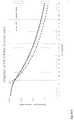
- FIG. 4shows the photopic contrast of an isolator of the present disclosure using the configuration of FIG. 3 .
- FIG. 5shows a reverse-order-reflection-about-zero (RORAZ) stack pair of the present disclosure used to convert between linear and circular polarization over a wide range of incidence angles and wavelengths.
- RORAZreverse-order-reflection-about-zero
- FIG. 6shows photopic contrast versus incidence angle (at the worst-case azimuth angle) for the FIG. 5 configuration of the present disclosure, compared to the prior art reverse-order-cross configuration; both without compensation.
- FIG. 7shows contrast versus incidence angle (at the worst-case azimuth angle) for the FIG. 5 configuration, compared to the prior art reverse-order-cross configuration with 200 nm of +C-plate compensation.
- FIG. 8shows green (540 nm) contrast versus azimuth angle at 30° incidence angle, for three configurations: (a) no compensation, (b) 130 nm of +C-plate compensation, and (c) a pair of CNAP retarders, each with 130 nm of retardation.
- FIG. 9shows a retarder stack pair of the present disclosure for converting between linear and 45° rotated linear polarization.
- FIG. 10shows photopic contrast for the FIG. 9 configuration, versus a prior art reverse-order-cross configuration
- the inventionmay be generally relevant to polarization transformations produced by linear retarder-stacks.
- the need for a retarder-stackis frequently borne out of necessity, owing to deficiencies in available anisotropic material properties. Such deficiencies can impact normal-incidence and/or off-normal behavior.
- an achromatic conversion from linear to circular polarizationcould in principle be accomplished in a single layer, using a linear retarder material that allows specifying the birefringence dispersion at all relevant wavelengths.
- an increase in optical pathlength-differencei.e. increase in birefringence
- n xis the refractive index in the stretching direction (usually the machine direction)
- n yis the refractive index in the transverse direction (or cross-web)
- dis the film thickness.
- These refractive indexesare wavelength-dependent, such that the difference (aka birefringence) typically decreases with wavelength.
- the usual phase retardationis the angle associated with the ratio of (wavelength-dependent) pathlength-difference to wavelength.
- n zis the refractive index in the thickness direction.
- n xn o (i.e. ordinary and extraordinary refractive index).
- R eaverage refractive index in-plane
- the thickness direction retardationhas the effect of modifying the complex amplitude of the impulse-train of a retarder stack, which typically degrades the polarization transformation.
- the specific nature of the degradationdepends upon the plane of incidence (POI) azimuth orientation relative to the distribution of retarders in the stack.
- POIplane of incidence
- AOIangle-of-incidence
- Bincreasing the number of layers to improve quality of a particular transformation increases the composite (or cumulative) R th , resulting in a more rapid decline in performance with AOI.
- Solutions to this probleminclude either the use of more exotic and/or complex retarder-stack materials, or designing optical systems with more collimated inputs. Neither of these may be practical in certain applications.
- FIG. 1shows a particular retarder stack pair of the prior art, where the normal-incidence retardation ( ⁇ r ) of each layer of Stack 1 is identical to that of the counterpart layer in Stack 2 .
- the corresponding layersare mirrored about the mid-point, as shown.
- the specific optic-axis angles ( ⁇ i ) for the layers of Stack 1depend upon the desired impulse response in transforming from PBV 1 to PBV 2 .
- the relationships between the angles of each of the corresponding layers of Stack 1 and Stack 2 ( ⁇ ′ i )may be further constrained if the objective is to (e.g.) restore PBV 1 .
- the Jones matrix for combined Stack 1 and Stack 2is in general the identity matrix (i.e. the off-diagonal terms are identically zero, and the diagonal components have the identical complex-amplitude).
- Thisis termed herein as the “trivial-case,” as Stack 2 can always be formed without regard for either the specific input basis vector (PBV 1 ), or the specific transformation to PBV 2 .
- the magnitude of the off-diagonal termsis minimized via the design (equivalent to stating that the magnitude of the diagonal terms is unity for a lossless retarder-stack), but an arbitrary phase-difference can exist between the diagonal components in the PBV 1 space.
- This phase-differenceis termed herein as a “linear compound-retardation,” and is a variable that can be exploited to identify designs with low composite R th .
- the Jones matrixis in general diagonal, it is termed an “eigen-polarization” of combined Stack 1 and Stack 2 .
- designs of the inventionrepresent Jones matrices in the PBV 1 space that represent non-trivial eigen-polarizations of combined Stack 1 and Stack 2 . Again, solutions in this broader design space are preferred that have inherently lower intrinsic AOI sensitivity than the trivial case.
- the stack pair transformationneed not be the identity matrix in some cases.
- the ROC arrangement for restoration of PBV 1may limit the inherent AOI sensitivity and/or effectiveness of compensation schemes in mitigating AOI dependence.
- the azimuth and wavelength dependence of R thcan make effective compensation of the ROC solution a practical impossibility.
- retarder-stack pairsaccomplish the required PBV transformations, with minimal composite R th , that respond well to practical compensation schemes for preserving performance over a broad range of wavelengths and incidence angles.
- the azimuth-dependence of R thcan be matched to a simple compensator (e.g. a C-plate), equal in magnitude, and opposite in sign, the structure can preserve the normal-incidence impulse response for all AOI.
- Stack 1produces one (or more) spectral bands over which the polarization is converted from PBV 1 to PBV 2 . It may further include designs where one (or more) spectral bands retain PBV 1 , along with one (or more) transition spectral bands where the SOP is in an intermediate polarization state.
- a method for designing Stack 1is to directly constrain the impulse response. Finite-impulse-response (FIR) filter design methodologies are known to be useful for identifying stack designs, though they do not in general allow specifying polarization transformations. Linear systems theory can relate the power transmission to the impulse response, where a set of designs that produce a particular transmission spectrum (typically between linear polarizers), can be identified.
- FIRFinite-impulse-response
- the objectiveis to identify the subset of stack designs that produce a particular polarization transformation spectrum from the more general solutions that satisfy the power transmission spectrum constraint.
- This additional constraintmay be imposed using retarder-stack pairs with certain (retardation/angle) symmetries.
- the SOP between the stacks (PBV 2 )is intermediate; such as circular, ⁇ 45° rotated linear, or other elliptical polarizations that lie in the (S 2 /S 3 ) plane of the Poincare sphere.
- the transformation to PBV 2and associated wavelength dependence, are actually arbitrary as may be required by the application. It may further be required that the second stack restores PBV 1 , or transform to another basis vector.
- the present disclosurerecognizes that the input polarization can be regarded an eigen-polarization of the combined Stack 1 and Stack 2 .
- the combinationrepresents a (lossless) diagonalized Jones matrix.
- the structurehas a compound optic-axis that is wavelength-stable and parallel/perpendicular to the input polarization.
- stack-pair designsthat transform from an achromatic first polarization basis vector (PBV 1 ), to a second achromatic polarization basis vector (PBV 2 ) using Stack 1 , and then transform the light to a state orthogonal to PBV 1 using Stack 2 .
- the stack pairhas a reverse-order (RO) relationship, or operates in reflection-mode (e.g. a retro-reflector follows Stack 1 ), which is effectively RO.
- ROreverse-order
- An example of thisis an optical isolator, where Stack 1 transforms from linear to circular polarization, with the reverse-order pass of Stack 1 converting from circular to orthogonal linear polarization.
- This lightis oriented along the absorption axis of a linear polarizer, and is therefore extinguished.
- this arrangementcan also be constructed by arranging Stack 2 to form the RO structure in transmission mode.
- stacks that effectively convert from linear to circular polarization over a broad range of wavelengthsmay require several layers, giving excellent normal-incidence behavior, but often at the expense of performance (e.g. isolator contrast) off-normal.
- An objective of the present disclosureis to identify optimum stack designs, using available (e.g. positive uniaxial) materials and practical compensation, that best preserve the normal-incidence impulse response over a range of incidence angles. Compensation typically refers to retarder layers that do not contribute to the polarization transformation at normal incidence, but which attempt to correct for polarization errors when light is incident off-normal. Rather than compensate each layer of a retarder stack, one approach of the invention is to explore design space for solutions that consolidate compensation to a single location (e.g.) between a stack pair. Methods for compensating to decouple normal-incidence performance from angle-of-incidence sensitivity in uniaxial stacks are described in co-pending US Patent Application Publication No.
- polarization switchessuch as liquid crystal devices.
- LC variable retarderscan be used to switch the orientation, ellipticity, phase, or handedness of an input polarization state.
- Retarder stackscan be used to transform the SOP to precondition for such modulation.
- broad-band transformations with wide acceptance anglecan be combined with wide-angle broad-band LC switches to create a new class of modulator.
- An example of the latteris disclosed in co-pending U.S. patent application Ser. No. 16/195,618, entitled “Self-Compensating Liquid Crystal Retardation Switch”, the entire contents of which are hereby incorporated by reference.
- Another exampleincludes a polarization-based isolator, typically composed of a linear absorptive polarizer followed by a quarter-wave retarder.
- a polarization-based isolatortypically composed of a linear absorptive polarizer followed by a quarter-wave retarder.
- light transmitted by the polarizer in the forward-passis absorbed by it in the reverse-pass, provided that return-light is from a down-stream pure specular reflection, and that the retarder provides a half-wave retardation in a round-trip.
- These simple isolatorswere used in applications such as eliminating glare from CRT monitors. Today they are relevant to (e.g.) sunlight-readability of mobile phones. This is particularly so for OLED displays, which are highly susceptible to reflection from the addressing structure. But because the OLED does not otherwise require a polarizer (versus e.g.
- isolatorcan be very effective.
- isolator contrastis limited by the wavelength and angle-of-incidence dependence of the conversion from linear to quasi-circular.
- the designs of the inventionare highly relevant to the OLED display.
- FIG. 16/260,903Another example includes wide-angle collimators, as described in co-pending U.S. patent application Ser. No. 16/260,903, entitled “Hollow Triple-Pass Optical Elements”, the entire contents of which are hereby incorporated by reference.
- a forward pass(Stack 1 +Stack 2 ) must restore the input SOP
- a subsequent double-passi.e. RO
- Such structuresmust typically operate over the entire visible band, and over a broad range of incidence angles in order to avoid stray light and ghost images.
- the objectiveis to use Stack 1 explicitly to maximize the bandwidth and dynamic range of the spectral range of conversion from PBV 1 to PBV 2 as much as possible.
- the composite R thwhich can modify (and in many instances increase) the compensation requirement.
- the latteris also specific to the polarization transformation, as will be shown in Examples 1 and 2.
- Optically-functional layersinclude all of the aforementioned examples, including compensation layers, passive/active components, polarization optics, refractive-elements, reflective-elements, diffractive-elements.
- the polarization transformation to PBV 2is intended to produce an optical response from the one or more optically functional layers that is closer to optimum than were PBV 1 introduced. In some instances, PBV 2 represents the optimum SOP, and thus it should be wavelength and AOI stable.
- Example 1 of the present disclosurea positive uniaxial retarder Stack 1 is used to convert from linear to circular polarization over a broad range of wavelengths.
- Stack 2either forms the reverse-order (RO) stack to convert to the orthogonal SOP, or Stack 1 is followed by a mirror, to force an effective RO arrangement in the reverse-pass.
- the designis required to operate over a broad range of visible wavelengths and to preserve that behavior off-normal via +C-plate compensation at a single location.
- a stack pairtransforms from a linear basis vector (PBV 1 ) to a circular polarization basis vector (PBV 2 ) at the mid-point, restoring PBV 1 after the second stack.
- Constrain a reverse-order (RO) stack(containing an odd number of layers) to convert as broad a spectral band as possible to the orthogonal SOP.
- the constraintcan use expansion of the off-diagonal terms of the impulse response in a Fourier sine-series. In this case, all layers have the same retardation which is half-wave at the design wavelength.
- RORAZreverse-order-reflection-about-zero
- a stack-pair with N layers and RO symmetry according to Step 1produces Stack 1 designs with (N+1)/2 layers.
- Table 1shows an example of preferred Stack 1 retardation/angles for RO designs with 3, 5, 7 and 9 layers. The table also shows the retardation/angle of the Stack 2 layers derived from Stack 1 according to Step 3 .
- the present disclosurerecognizes that not all of the stack designs with the identical (normal-incidence) impulse response have the same off-normal behavior. Moreover, not all of the stack designs can be compensated effectively using available (e.g. C-plate) compensators.
- One preferred family of solutionsis illustrated in FIG. 3 , including a particular arrangement of half-wave (HW) retarders followed by a single quarter-wave (QW) retarder. Specifically, the HW retarders have a successively increasing orientation (i.e. ⁇ 2 >2 ⁇ 1 , ⁇ 3 >2 ⁇ 2 , etc), as shown in Table 1, such that the magnitude of the polarization transformations observed on the Poincare sphere grows with each HW retarder.
- the net effectis a rotated linear state at the design wavelength, where the orientation of the polarization exiting the final HW retarder forms an angle of 45° with respect to the optic axis of the QW retarder.
- the purpose of the HW stackis to precondition the SOP, matching the ellipticity spectrum to that introduced in the final transformation by the QW retarder. Under ideal circumstances, this match allows the QW retarder to transform all relevant wavelengths to a pole of the Poincare sphere.
- the objective of the half-wave stackis to produce a fixed polarization orientation (i.e. all wavelengths having the same longitude on the Poincare sphere) with ellipticity spectrum matched to that of the quarter-wave retarder (i.e. the spectral distribution of ellipticity in latitude above/below the equator).
- green lightmay lie on the equator, with blue below, and red above, such that the QW retarder maps all three bands to the pole.
- This transformationcan become more precise as the number of layers increases, and with enough HW layers, can be a virtual identical match to that introduced by the QW retarder. Light exiting the QW can therefore in principle have unity ellipticity at all wavelengths.
- the present disclosureanticipates the need for specific retarder-stack designs that transform a broad-range of wavelengths from a linear to a circular SOP (and vice-versa), which are also effectively compensated using available materials (e.g. +C-Plate retarders).
- +C-plate retarderswere developed for the display industry using reactive-mesogens, or liquid-crystal-polymer coatings that can be applied directly to the retarder stack.
- the family of stack designs conforming to FIG. 3can have these properties and are preferred over other designs with the same impulse response.
- Example 1 of the present disclosurethe performance is characterized here using metric 3 above.
- the design selectedis that using three HW layers, with angles shown in Table 1.
- the modelrepresents a true double-pass of Stack 1 , with C-plate compensation retardation selected to minimize off-normal leakage through the polarizer in the return pass.
- an ideal isolatorproduces a linear SOP along the polarizer absorption axis after a double-pass of Stack 1 for all relevant wavelengths and incidence angles. The inverse of this gives the contrast of the isolator.
- ⁇65.2°, giving a calculated QW angle of ⁇ 69.8°.
- FIG. 4is a line-plot through the contrast polar plot at the worst-case azimuth as a function of incidence angle. The contrast is calculated as the ratio of input lumens divided by the leakage lumens through the polarizer after a double-pass of the stack assuming a flat-top input spectrum.
- the HW/QW retardersare dispersionless, with a center wavelength of 500 nm, and the dispersionless C-Plate has a positive R th of 80 nm (single-pass).
- the polarizerhas zero transmission along the absorption axis and unity transmission in the orthogonal direction.
- Example 2 of the inventionthe four design steps taught herein are used to convert from a linear PBV 1 to a circular PBV 2 via stack 1 , followed by restoration of the input SOP via Stack 2 .
- the performanceis benchmarked against a design using the prior art ROC approach, where all of the four metrics are relevant.
- Both the inventive and prior art design approachescan identify the same Stack 1 , so it is assumed that metric 1 above is the same for both.
- Metric 3can be optimized by selecting a C-plate retardation that maximizes the angular performance of the stack pair.
- Metric 2is exemplary for the ROC arrangement, since it yields the identity matrix, though it is design-dependent for the techniques taught herein. The comparison focuses to a great extent on comparison of metric 4 .
- optimizing compensation for metric 3 and metric 4can be done independently, according to Step 4 .
- the objectiveis to identify Stack 1 compensation that optimizes off-normal stability of PBV 2 , that is also compatible with compensation of the combined stacks.
- a C-plate compensator with retardation ⁇ 1may optimize PBV 2
- a C-plate compensator with retardation ⁇ 2optimizes the overall transformation. This can be accomplished using a pair of C-plates with retardation ⁇ 1 and retardation ( ⁇ 2 ⁇ i ).
- FIG. 5is an example of this.
- FIG. 5shows the arrangement of an optimized design according to Example 2.
- FIG. 7compares the angle-dependent contrast of the compensated ROC arrangement and that of the techniques taught herein at the worst-case azimuth. As before, the ROC design has better performance at small angle, though the cross-over contrast now is approximately 6,000:1. For all larger angles, the techniques taught herein perform substantially better. Comparing FIG. 6 to FIG.
- FIG. 7shows that, while the ROC case has incremental contrast improvement with compensation, the RORAZ case has a dramatic improvement. Again, this is because a large proportion of the retardation introduced by R th off-normal has a relatively uniform behavior in azimuth, and as such, can be compensated with a single +C-plate.
- FIG. 7shows that the 1,000:1 contrast boundary is at approximately 26° AOI, 500:1 at 32°, 200:1 at 41°, and well over 100:1 at 46°. For any AOI above 24°, the techniques taught herein deliver 8-9 ⁇ higher contrast than the compensated ROC case.
- Compensation for stack R thcan take many forms.
- R this positive, usually requiring a compensator with a negative R th .
- Examples of thisinclude positive C-plates (positive uniaxial material with optic axis normal to the substrate), or crossed negative A-plates (negative uniaxial materials with optic axis in-plane) with matched retardation.
- Typical solutionsinclude biaxially stretched uniaxial films, liquid crystal polymers and even inorganic crystals. The main difference between the behavior of these is the azimuth dependence of the applied compensation. Neither compensator affects the SOP at normal incidence. In the case where the SOP between the stacks is substantially circular, both compensators apply a retardation shift to any light incident off-normal.
- the magnitude of the compensationincreases with AOI.
- the differenceis that the projected optic axis orientation for the C-plate is in general contained in the plane of incidence (POI), while the optic axis of the crossed negative A-plate (CNAP) configuration is substantially fixed in orientation.
- the two compensatorsperform substantially the same (assuming all have the same base retardation).
- the difference in azimuth angle between the two compensator optic axis orientationsis at a maximum.
- the optic axes of the CNAP retardersno longer appear crossed due to geometrical rotation.
- the amount of compensation neededdepends upon the specific stack design. Combinations of C-plate and CNAP compensators can be used in various configurations to best achieve this.
- the RORAZ design of Example 2demonstrates the difference between two simple cases where positive C-Plate and CNAPs compensators are used with this stack design.
- the metric used hereis the elevation angle (EA) for the SOP exiting Stack 1 with respect to the equator of the Poincare sphere, which is a measure of the ellipticity of PBV 2 .
- the ideal elevation angleis of course 90°, or unity ellipticity.
- the ellipticitycould also be expressed as a field-ratio in the frame of the elliptical polarization, where the field-ratio (FR) is unity for a circular SOP.
- the aggregated ellipticity field-ratiocould also be expressed as photopically-weighted in the event that the eye is used as the sensor.
- the purpose of a compensatoris to minimize the composite R th in order to maintain the aggregated FR near unity over as broad a range of incidence angles as possible.
- a stack pairgenerates an achromatic 45° rotated linear polarization basis vector (PBV 2 ) at the mid-point, while restoring PBV 1 after the second stack.
- PBV 2linear polarization basis vector
- a stack pair with RORAZ symmetry according to Step 1 with N layersproduces Stack 1 designs with N/2 layers.
- Table 2 examplesrepresent a particular set of solutions where the HW layers have a “fan” characteristic, as in Example 2. The table also shows the Stack 2 angles derived from Stack 1 .
- the layersare all half-wave retarders at 530 nm, with zero birefringence dispersion.
- Example 3rotator
- metric 4is used in this case to compare native contrast performance of Example 3 to the ROC counterpart.
- FIG. 9shows the (metric 4 ) contrast versus incidence angle at the worst-case azimuth for the Example 3 design and for the ROC counterpart.
- the ROC designdelivers higher contrast below 8°, but the contrast of Example 3 remains above 10,000:1 for angles smaller than this.
- the Example 3 designprovides contrast between 3-4 ⁇ greater than that of the ROC design.
- Stack 1can be designed to produce a particular PBV transformation.
- a design angle symmetryis then exploited between Stack 1 and Stack 2 to restore the input PBV (e.g. Examples 2 and 3). It could alternatively be used to transform to a third PBV, as in Example 1.
- the set of solutionscan in general be compensated at the mid-point to mitigate degradation of the normal-incidence impulse-response. This applies to arbitrary PBV cases, with the three examples given to illustrate the design methodology. It also includes (e.g.) PBV transformations from linear to orthogonal linear, circular to linear, circular to circular (of opposite handedness), etc. The examples given are illustrative, but are not intended to limit the scope of the invention.
- Wide-angle wavelength selective polarization transformationsare useful in, for example, image projection and direct-view display, image capture, sensors, polarization metrology, augmented/virtual/mixed-reality headsets, sunglasses, spectrometry, and telecommunications.
- the techniques taught hereincan be applied to any situation where preservation of the normal-incidence impulse response of a retarder-stack must be maintained when light is incident off-normal. These techniques are particularly useful in situations where the building blocks are uniaxial retarders, or any retarder with non-zero R th .
- the designs taught hereincan be applied to any spectral band, including UV, near-infrared, and infrared bands.
- Applicable materialsinclude any organic or inorganic layer that functions as a linear retarder.
- Stretched organic retarder materialsinclude polycarbonate (PC), polycarbonate co-polymers, polystyrene, and cyclic-olefin polymer (COP) or cyclic-olefin co-polymer (COC). Further included are liquid crystal polymers/reactive mesogens.
- Inorganic materialsinclude crystals such as quartz, lithium niobate, and sapphire.
- Embodiments of the inventionthat are designed to be broad-band (e.g. achromatic) benefit from base retarder materials with low birefringence dispersion.
- base retarder materialse.g. achromatic
- COPhas lower birefringence dispersion than PC so a particular achromatic stack design has broader spectral coverage with the former.
- the present disclosurerecognizes the value of going beyond this; forming achromatic retarder stacks using a base-film that has reverse-dispersion (i.e. birefringence increases with wavelength).
- a base film that is already quasi-achromaticcan produce a retarder stack with extreme wavelength insensitivity using a simple stack design with just a few layers.
- Teijinmanufactures a co-polymer that has such reverse dispersion (WR-M) that can be used as the base-film of an achromatic retarder stack.
- WR-Mreverse dispersion
- the three-HW layer stack of Table 1can be used to create an isolator with broader spectral coverage than the zero-dispersion case shown in Example 1.
- a sufficiently achromatic base filmcan produce the normal-incidence performance of the three-HW layer stack using two HW layers, or potentially even one HW layer.
Landscapes
- Physics & Mathematics (AREA)
- General Physics & Mathematics (AREA)
- Optics & Photonics (AREA)
- Chemical & Material Sciences (AREA)
- Crystallography & Structural Chemistry (AREA)
- Polarising Elements (AREA)
Abstract
Description
- 1. Constrain the first stack design directly by forcing a particular PBV2 from the specific PBV1. Alternatively, constrain the impulse response of a stack pair possessing a particular symmetry in such a way that a particular PBV2 is forced.
- 2. Arrange the second stack to form a reverse-order-crossed (ROC) stack pair, as shown in
FIG. 2 . In the ROC arrangement, each layer inStack 1 has the same retardation and is crossed with the counterpart layer inStack 2. This configuration guarantees that the composite Jones matrix is the identity matrix at normal incidence, regardless of PBV2, and therefore that the original PBV1 is restored at all wavelengths. - 3. Insert Rthcompensation as needed to best maintain the normal-incidence impulse response over the range of incidence angles and wavelengths.
- 1. Normal incidence polarization ellipticity spectrum of PBV2. Again, this is limited by material (dispersion) properties, N, and somewhat by the choice of center wavelength. A method for evaluating this is modeling/measuring
Stack 1 paired with the RO version ofStack 1 and evaluating the (e.g.) photopic contrast between parallel polarizers. The ability of the stack pair to convert to the orthogonal SOP is an indication of the ellipticity of PBV2. - 2. Normal incidence restoration of PBV1. For the present, where ROC is not used, this can also be influenced by N and center wavelength. Performance can be given by the (e.g. photopic) contrast of the stack pair between crossed polarizers. Recall that ROC gives infinite contrast here for all PBV2, but solutions discussed herein may require that PBV1 is a stable eigenpolarization of the combined stacks. The associated transformation may be imperfect, limiting contrast.
- 3. AOI dependence of polarization ellipticity spectrum of PBV2 for compensated
Stack 1. As inmetric 1, a potential way to model/measure this is by pairingStack 1 with the RO version ofStack 1 and evaluating the contrast polar plot between parallel polarizers - 4. AOI dependent of the restoration of PBV1. As in
metric 2, a potential way to model/measure this is by pairing compensatedStack 1 andStack 2 and evaluating the contrast polar plot between crossed polarizers.
- 1. Normal incidence polarization ellipticity spectrum of PBV2. Again, this is limited by material (dispersion) properties, N, and somewhat by the choice of center wavelength. A method for evaluating this is modeling/measuring
| TABLE 1 |
| Stack designs according to Example 2 steps. |
| N | (N + 1)/2 | Retardation/Angle |
| 3 | 2 | (H) 14.9° (Q) 73.9°/(Q) −73.9° (H) −14.9° |
| 5 | 3 | (H) 4.5° (H) 28.9° (Q) −86.5°/(Q) 86.5° (H) −28.9°, |
| (H) −4.5°, | ||
| 7 | 4 | (H) 1.5° (H) 11.2° (H) 42.3° (Q) −70.0°/(Q) 70.0° |
| (H) −42.3° (H) −11.2° (H) −1.5° | ||
| 9 | 5 | (H) 1.2° (H) 8.8° (H) 32.3° (H) 80.9° (Q) −22.5°/ |
| (Q) 22.5° (H) −80.9° (H) −32.3° (H) −8.8°(H) −1.2° | ||
- 1. Constrain a RORAZ stack (containing an even number of layers) to convert as broad a spectral band as possible to the orthogonal SOP. The constraint can use expansion of the off-diagonal terms of the impulse response in a Fourier cosine-series. In this case, all layers have the same retardation which is half-wave at the design wavelength.
- 2. Divide the RORAZ stack in half, forming
Stack 1. Because the stack pair has an even number of layers, all layers ofStack 1 are half-wave at the design wavelength. In order for the RORAZ stack to convert to the orthogonal SOP, it must do so with rotation only (zero retardation). As such, the SOP at the mid-point is constrained to be 45° linear. - 3.
Form Stack 2 as the reverse-order (RO) arrangement ofStack 1. A characteristic of RO is that it nullifies any rotation fromStack 1, while doubling retardation. Since the RO design is constrained to have minimal rotation, the arrangement can restore the original SOP.
| TABLE 2 |
| Stack pair according to Example 2 design steps. All |
| layers are half-wave at the design wavelength. |
| N | N/2 | Angle |
| 4 | 2 | 10.5° 32.9°/32.9° 10.5° |
| 6 | 3 | 4.3° 19.6° 37.8°/37.8° 19.6° 4.3° |
| 8 | 4 | 1.7° 10.0° 26.1° 40.2°/40.2° 26.1° 10.0° 1.7° |
| 10 | 5 | 1.2° 7.1° 19.9° 34.4° 43.0°/43.0° 34.4° 19.9° 7.1° 1.2° |
Claims (28)
Priority Applications (2)
| Application Number | Priority Date | Filing Date | Title |
|---|---|---|---|
| US16/289,335US11320665B2 (en) | 2018-03-02 | 2019-02-28 | Retarder stack pairs for polarization basis vector transformations |
| US17/660,996US20220260845A1 (en) | 2018-03-02 | 2022-04-27 | Retarder stack pairs for polarization basis vector transformations |
Applications Claiming Priority (2)
| Application Number | Priority Date | Filing Date | Title |
|---|---|---|---|
| US201862637832P | 2018-03-02 | 2018-03-02 | |
| US16/289,335US11320665B2 (en) | 2018-03-02 | 2019-02-28 | Retarder stack pairs for polarization basis vector transformations |
Related Child Applications (1)
| Application Number | Title | Priority Date | Filing Date |
|---|---|---|---|
| US17/660,996ContinuationUS20220260845A1 (en) | 2018-03-02 | 2022-04-27 | Retarder stack pairs for polarization basis vector transformations |
Publications (2)
| Publication Number | Publication Date |
|---|---|
| US20190271853A1 US20190271853A1 (en) | 2019-09-05 |
| US11320665B2true US11320665B2 (en) | 2022-05-03 |
Family
ID=67768577
Family Applications (2)
| Application Number | Title | Priority Date | Filing Date |
|---|---|---|---|
| US16/289,335Active2039-11-24US11320665B2 (en) | 2018-03-02 | 2019-02-28 | Retarder stack pairs for polarization basis vector transformations |
| US17/660,996AbandonedUS20220260845A1 (en) | 2018-03-02 | 2022-04-27 | Retarder stack pairs for polarization basis vector transformations |
Family Applications After (1)
| Application Number | Title | Priority Date | Filing Date |
|---|---|---|---|
| US17/660,996AbandonedUS20220260845A1 (en) | 2018-03-02 | 2022-04-27 | Retarder stack pairs for polarization basis vector transformations |
Country Status (5)
| Country | Link |
|---|---|
| US (2) | US11320665B2 (en) |
| EP (1) | EP3759531A4 (en) |
| JP (1) | JP7284182B2 (en) |
| CN (2) | CN115685432A (en) |
| WO (1) | WO2019169170A1 (en) |
Cited By (3)
| Publication number | Priority date | Publication date | Assignee | Title |
|---|---|---|---|---|
| US20220260845A1 (en)* | 2018-03-02 | 2022-08-18 | Gary Sharp Innovations, Inc. | Retarder stack pairs for polarization basis vector transformations |
| US20240242665A1 (en)* | 2021-07-05 | 2024-07-18 | Jdi Design And Development G.K. | Tiling panel, self-luminous panel, and manufacturing method |
| US12276882B2 (en) | 2023-07-19 | 2025-04-15 | Samsung Display Co., Ltd. | Display device |
Families Citing this family (7)
| Publication number | Priority date | Publication date | Assignee | Title |
|---|---|---|---|---|
| JP7263643B2 (en) | 2017-03-08 | 2023-04-25 | メタ プラットフォームズ テクノロジーズ, リミテッド ライアビリティ カンパニー | Wide angle variable neutral density filter |
| CN111108428A (en) | 2017-07-17 | 2020-05-05 | 加里夏普创新有限责任公司 | Wide angle compensation of uniaxial retarder stacks |
| US11249355B2 (en) | 2018-01-29 | 2022-02-15 | Gary Sharp Innovations, Llc | Color switch for reduced color cross-talk |
| EP3746822A4 (en) | 2018-01-29 | 2022-01-12 | Gary Sharp Innovations, LLC | Hollow triple-pass optical elements |
| US11269131B2 (en)* | 2020-03-16 | 2022-03-08 | Facebook Technologies, Llc | Liquid crystal reflective polarizer and pancake lens assembly having the same |
| CN115698782A (en) | 2020-03-25 | 2023-02-03 | 奇跃公司 | Optical device with a single-way mirror |
| JP2024057839A (en)* | 2022-10-13 | 2024-04-25 | 日東電工株式会社 | Optical laminate |
Citations (157)
| Publication number | Priority date | Publication date | Assignee | Title |
|---|---|---|---|---|
| US4511225A (en) | 1982-12-23 | 1985-04-16 | Lipson Herbert G | Variable neutral density laser goggles |
| US4884876A (en) | 1983-10-30 | 1989-12-05 | Stereographics Corporation | Achromatic liquid crystal shutter for stereoscopic and other applications |
| US5132826A (en) | 1989-10-30 | 1992-07-21 | The University Of Colorado Foundation, Inc. | Ferroelectric liquid crystal tunable filters and color generation |
| US5231521A (en) | 1989-10-30 | 1993-07-27 | The University Of Colorado Foundation, Inc. | Chiral smectic liquid crystal polarization interference filters |
| US5243455A (en) | 1990-05-11 | 1993-09-07 | The University Of Colorado Foundation, Inc. | Chiral smectic liquid crystal polarization interference filters |
| US5381253A (en) | 1991-11-14 | 1995-01-10 | Board Of Regents Of University Of Colorado | Chiral smectic liquid crystal optical modulators having variable retardation |
| US5387958A (en) | 1992-06-30 | 1995-02-07 | Sony Electronics, Inc. | Electro-optical control of light attenuation in the optical path of a camera |
| US5493426A (en) | 1991-11-14 | 1996-02-20 | University Of Colorado Foundation, Inc. | Lateral electrode smectic liquid crystal devices |
| US5528393A (en) | 1989-10-30 | 1996-06-18 | Regents Of The University Of Colorado | Split-element liquid crystal tunable optical filter |
| US5552912A (en) | 1991-11-14 | 1996-09-03 | Board Of Regents Of The University Of Colorado | Chiral smectic liquid crystal optical modulators |
| US5574553A (en) | 1994-12-27 | 1996-11-12 | The United States Of America As Represented By The Secretary Of The Air Force | Ladar receiver incorporating an optical amplifier and polarization optical mixer |
| US5619355A (en) | 1993-10-05 | 1997-04-08 | The Regents Of The University Of Colorado | Liquid crystal handedness switch and color filter |
| US5627666A (en) | 1994-07-27 | 1997-05-06 | Board Of Regents Of The University Of Colorado | Liquid crystal phase modulator using cholesteric circular polarizers |
| US5658490A (en) | 1995-04-07 | 1997-08-19 | Board Of Regents Of The University Of Colorado | Liquid crystal achromatic compound retarder |
| US5689317A (en) | 1995-03-22 | 1997-11-18 | Cambridge Research Instrumentation, Inc. | Tunable color filter |
| US5715023A (en) | 1996-04-30 | 1998-02-03 | Kaiser Electro-Optics, Inc. | Plane parallel optical collimating device employing a cholesteric liquid crystal |
| US5751384A (en) | 1995-05-23 | 1998-05-12 | The Board Of Regents Of The University Of Colorado | Color polarizers for polarizing an additive color spectrum along a first axis and it's compliment along a second axis |
| US5781268A (en) | 1996-04-09 | 1998-07-14 | Board Of Regents Of The University Of Colorado | Polarization-insensitive fabry-perot tunable filter |
| US5822021A (en) | 1996-05-14 | 1998-10-13 | Colorlink, Inc. | Color shutter liquid crystal display system |
| US5870159A (en) | 1995-10-30 | 1999-02-09 | Kaj | Switchable achromatic polarization rotator |
| US5892559A (en) | 1996-11-25 | 1999-04-06 | Colorlink, Inc. | Chromaticity compensating liquid crystal filter |
| US5892612A (en) | 1997-08-07 | 1999-04-06 | Cambridge Research & Instrumentation Inc. | Tunable optical filter with white state |
| US5929946A (en) | 1995-05-23 | 1999-07-27 | Colorlink, Inc. | Retarder stack for preconditioning light for a modulator having modulation and isotropic states of polarization |
| US5999240A (en) | 1995-05-23 | 1999-12-07 | Colorlink, Inc. | Optical retarder stack pair for transforming input light into polarization states having saturated color spectra |
| US6028656A (en) | 1996-10-09 | 2000-02-22 | Cambridge Research & Instrumentation Inc. | Optical polarization switch and method of using same |
| US6049367A (en) | 1995-05-23 | 2000-04-11 | Colorlink, Inc. | Polarization manipulating device modulator with retarder stack which preconditions light for modulation and isotropic states |
| US6075651A (en) | 1999-01-28 | 2000-06-13 | Kaiser Electro-Optics, Inc. | Compact collimating apparatus |
| US6078374A (en) | 1995-04-07 | 2000-06-20 | Colorlink, Inc. | Spatially switched achromatic compound retarder |
| US6141071A (en) | 1995-10-30 | 2000-10-31 | Colorlink, Inc. | Switchable achromatic polarization rotator |
| US6183091B1 (en) | 1995-04-07 | 2001-02-06 | Colorlink, Inc. | Color imaging systems and methods |
| US6252638B1 (en) | 1995-05-23 | 2001-06-26 | Colorlink, Inc. | Color controllable illumination device, indicator lights, transmissive windows and color filters employing retarder stacks |
| US6273571B1 (en) | 1995-05-23 | 2001-08-14 | Colorlink, Inc. | Display architectures using an electronically controlled optical retarder stack |
| US6380997B1 (en) | 1995-04-07 | 2002-04-30 | Colorlink, Inc. | Achromatic polarization inverters for displaying inverse frames in DC balanced liquid crystal displays |
| US6417892B1 (en) | 1995-05-23 | 2002-07-09 | Colorlink, Inc. | Color filters, sequencers and displays using color selective light modulators |
| US6630037B1 (en) | 1998-08-25 | 2003-10-07 | Kobe Steel, Ltd. | High strength aluminum alloy forgings |
| US6638583B1 (en) | 2000-03-16 | 2003-10-28 | Colorlink, Inc. | Method and apparatus for laminating stacks of polycarbonate films |
| US6650377B2 (en) | 2000-05-08 | 2003-11-18 | Colorlink, Inc. | Two panel projection systems |
| US6704065B1 (en) | 1995-04-07 | 2004-03-09 | Colorlink, Inc. | Optical system for producing a modulated color image |
| US6707516B1 (en) | 1995-05-23 | 2004-03-16 | Colorlink, Inc. | Single-panel field-sequential color display systems |
| US6735017B1 (en) | 1997-11-26 | 2004-05-11 | Sharp Kabushiki Kaisha | Broadband optical retardation device |
| US6816309B2 (en) | 2001-11-30 | 2004-11-09 | Colorlink, Inc. | Compensated color management systems and methods |
| US6882384B1 (en) | 1995-05-23 | 2005-04-19 | Colorlink, Inc. | Color filters and sequencers using color selective light modulators |
| US6922221B2 (en) | 2002-10-17 | 2005-07-26 | Research Foundation Of The University Of Central Florida | Broadband quarter-wave film device including in combination a chromatic half-wave film and a TN-LC polymeric film |
| US6961179B2 (en) | 2001-11-30 | 2005-11-01 | Colorlink, Inc. | Compensated color management systems and methods |
| US7002752B2 (en) | 2001-11-30 | 2006-02-21 | Colorlink, Inc. | Three-panel color management systems and methods |
| US7083282B1 (en) | 2002-02-19 | 2006-08-01 | Colorlink, Inc. | Light recycling colored light source and method of using |
| US7106509B2 (en) | 2002-09-06 | 2006-09-12 | Colorlink, Inc. | Filter for enhancing vision and/or protecting the eyes and method of making a filter |
| US7126649B2 (en) | 2002-10-30 | 2006-10-24 | Colorlink, Inc. | Oblique plate compensators for projection display systems |
| US7154667B2 (en) | 2002-08-30 | 2006-12-26 | Colorlink, Inc. | Birefringent networks |
| US7195356B1 (en) | 2003-09-22 | 2007-03-27 | Colorlink, Inc. | Split-path color switching system and method |
| US7298386B1 (en) | 2002-05-14 | 2007-11-20 | Colorlink, Inc. | Sequential color display system and method |
| US7345723B2 (en) | 2004-05-24 | 2008-03-18 | Colorlink, Inc. | LC panel compensators |
| US7436476B2 (en) | 2004-05-24 | 2008-10-14 | Real D | High durability and high performance polarization optics using a low-elasticity organic layer |
| US7510280B2 (en) | 2005-08-30 | 2009-03-31 | Real D | High yield bonding process for manufacturing polycarbonate polarized lenses |
| US7528906B2 (en) | 2006-01-23 | 2009-05-05 | Real D | Achromatic polarization switches |
| US7583439B2 (en) | 2007-08-09 | 2009-09-01 | University Of Central Florida Research Foundation, Inc. | Wide-angle and broadband polarization converter |
| US7692746B2 (en) | 2005-08-01 | 2010-04-06 | Real D | Digitally-switchable bandpass filter |
| US7898734B2 (en) | 2008-01-28 | 2011-03-01 | Reald Inc. | Polarization preserving front projection screen |
| US7898603B2 (en) | 2006-11-30 | 2011-03-01 | Reald Inc. | Double-shutter lenses with compensators |
| US7905602B2 (en) | 2006-09-29 | 2011-03-15 | Reald Inc. | Polarization conversion systems for stereoscopic projection |
| US8085644B2 (en) | 2004-12-16 | 2011-12-27 | Reald Inc. | Achromatic polarization devices for optical disc pickup heads |
| US8169699B2 (en) | 2009-12-22 | 2012-05-01 | Reald Inc. | Polarization preserving projection screen with engineered pigment and method for making same |
| US8184215B2 (en) | 2010-08-17 | 2012-05-22 | Lc-Tec Displays Ab | High-speed liquid crystal polarization modulator |
| US8194315B2 (en) | 2009-12-22 | 2012-06-05 | ReaID Inc. | Polarization preserving projection screen with engineered particle and method for making same |
| US8233034B2 (en) | 2006-02-10 | 2012-07-31 | Reald Inc. | Multi-functional active matrix liquid crystal displays |
| US8330911B2 (en) | 2005-06-27 | 2012-12-11 | University Of Central Florida Research Foundation, Inc. | Wide-acceptance-angle circular polarizers |
| US8328362B2 (en) | 2010-02-24 | 2012-12-11 | Reald Inc. | Waveplate compensation in projection polarization conversion system |
| US8403488B2 (en) | 2009-06-29 | 2013-03-26 | Reald Inc. | Stereoscopic projection system employing spatial multiplexing at an intermediate image plane |
| US8408708B2 (en) | 2009-05-22 | 2013-04-02 | Reald Inc. | Polarization modulation wheel |
| US8427394B2 (en) | 2006-11-30 | 2013-04-23 | Reald Inc. | Shutter glass drive scheme for sequential-color displays |
| US8425041B2 (en) | 2008-12-01 | 2013-04-23 | Reald Inc. | Stereoscopic projection systems for employing spatial multiplexing at an intermediate image plane |
| US8488240B2 (en) | 2009-12-22 | 2013-07-16 | Reald Inc. | Polarization preserving projection screen with engineered pigment and method for making same |
| US8526106B2 (en) | 2011-03-09 | 2013-09-03 | Reald Inc. | Method and apparatus for managing optical non-uniformities in seaming processes |
| US8638400B2 (en) | 2010-07-13 | 2014-01-28 | Reald Inc. | Field-of-view compensated polarization switch for short-throw 3D projection |
| US8687275B2 (en) | 2007-10-11 | 2014-04-01 | Reald Inc. | Curved retarder-based optical filters |
| US8724218B2 (en) | 2011-07-07 | 2014-05-13 | Reald Inc. | Speckle reduction using screen vibration techniques and apparatus |
| US8727536B2 (en) | 2007-05-09 | 2014-05-20 | Reald Inc. | Polarization conversion system and method for projecting polarization encoded imagery |
| US8746876B2 (en) | 2011-02-24 | 2014-06-10 | Reald Inc. | Stereoscopic eyewear with stray light management |
| US8760760B2 (en) | 2010-09-30 | 2014-06-24 | Reald Inc. | Cleanable coating for projection screen |
| US8820937B2 (en) | 2010-08-17 | 2014-09-02 | Lc-Tec Displays Ab | Optical polarization state modulator assembly for use in stereoscopic three-dimensional image projection system |
| US8851680B2 (en) | 2011-05-12 | 2014-10-07 | Reald Inc. | Polarization compensated stereoscopic systems |
| US8891042B1 (en) | 2013-09-23 | 2014-11-18 | Lc-Tec Displays Ab | Electro-optic liquid crystal camera iris providing angle independent transmission for uniform gray shades |
| US8908081B2 (en) | 2010-09-09 | 2014-12-09 | Red.Com, Inc. | Optical filter opacity control for reducing temporal aliasing in motion picture capture |
| US8941801B2 (en) | 2011-06-14 | 2015-01-27 | Reald Inc. | In-plane switched active retarder for stereoscopic display systems |
| US9046755B2 (en) | 2012-09-06 | 2015-06-02 | Reald Inc. | High elastic modulus projection screen substrates |
| US9057880B2 (en) | 2011-11-30 | 2015-06-16 | Reald Inc. | Laser beam scanned display apparatus and method thereof |
| US9121999B2 (en) | 2013-07-30 | 2015-09-01 | Au Optronics Corporation | Optical film and display device having the same |
| US9223142B2 (en) | 2010-01-20 | 2015-12-29 | Reald Inc. | Stereoscopic projection system with multiple power groups |
| US9229139B2 (en) | 2012-01-19 | 2016-01-05 | Lc-Tec Displays Ab | Enhanced vision system implemented with optical shutter alternately transmitting visible radiation and near infrared radiation |
| US9235057B2 (en) | 2012-05-18 | 2016-01-12 | Reald Inc. | Polarization recovery in a directional display device |
| US9316865B2 (en) | 2012-01-19 | 2016-04-19 | Lc-Tec Displays Ab | Rapid switching optical shutter alternately transmitting visible radiation and near infrared radiation |
| US20160109730A1 (en) | 2004-03-22 | 2016-04-21 | Fakespace Labs, Inc. | Electrically Controlled Optical Elements and Method |
| US9350980B2 (en) | 2012-05-18 | 2016-05-24 | Reald Inc. | Crosstalk suppression in a directional backlight |
| US9380220B2 (en) | 2013-04-05 | 2016-06-28 | Red.Com, Inc. | Optical filtering for cameras |
| US9530397B2 (en) | 2012-03-06 | 2016-12-27 | Reald Inc. | Light efficient acoustically transmissive front projection screens |
| US9618765B2 (en) | 2014-10-21 | 2017-04-11 | Reald Inc. | High power handling polarization switches |
| US9625745B2 (en) | 2013-11-15 | 2017-04-18 | Reald Inc. | High dynamic range, high contrast projection systems |
| US9664945B2 (en) | 2013-03-29 | 2017-05-30 | Au Optronics Corporation | Display apparatus |
| US9680132B1 (en) | 2015-11-30 | 2017-06-13 | Industrial Technology Research Institute | Display device and optical film |
| US9823561B2 (en) | 2011-07-13 | 2017-11-21 | Reald Inc. | Method and apparatus for joining screen material for minimal optical distortion |
| US20180039004A1 (en) | 2015-09-03 | 2018-02-08 | 3M Innovative Properties Company | Optical system and magnifying device |
| US20180039052A1 (en) | 2016-08-02 | 2018-02-08 | Apple Inc. | Optical System for Head-Mounted Display |
| US9933636B2 (en)* | 2015-10-23 | 2018-04-03 | Gary D. Sharp | Optical filter with color enhancement |
| US9933631B2 (en) | 2016-03-28 | 2018-04-03 | Lc-Tec Displays Ab | Electro-optic guest-host liquid crystal variable transmission filter with wide viewing angle |
| US9946088B2 (en) | 2010-06-08 | 2018-04-17 | Reald Inc. | Stereoscopic liquid crystal display systems |
| US10012884B2 (en) | 2013-09-23 | 2018-07-03 | Lc-Tec Displays Ab | High contrast electro-optic liquid crystal camera iris providing angle independent transmission for uniform gray shades |
| US20180210223A1 (en) | 2017-01-24 | 2018-07-26 | Gary D. Sharp | Tunable color enhancement filter |
| US10049627B2 (en) | 2013-01-04 | 2018-08-14 | Reald Inc. | Multi-primary backlight for multi-functional active-matrix liquid crystal displays |
| US20180259692A1 (en) | 2017-03-08 | 2018-09-13 | Gary D. Sharp | Wide angle variable neutral density filter |
| US10082675B2 (en) | 2014-10-21 | 2018-09-25 | Reald Inc. | High power handling polarization switches |
| US20190018177A1 (en) | 2017-07-17 | 2019-01-17 | Gary D. Sharp | Wide-angle compensation of uniaxial retarder stacks |
| US20190235145A1 (en) | 2018-01-29 | 2019-08-01 | Gary D. Sharp | Hollow triple-pass optical elements |
| US20190235300A1 (en) | 2018-01-29 | 2019-08-01 | Gary D. Sharp | Color switch for reduced color cross-talk |
| US10393946B2 (en) | 2010-11-19 | 2019-08-27 | Reald Spark, Llc | Method of manufacturing directional backlight apparatus and directional structured optical film |
| US10394040B2 (en) | 2016-10-12 | 2019-08-27 | Facebook Technologies, Llc | Head mounted display including pancake lens block |
| US10401700B2 (en) | 2013-09-23 | 2019-09-03 | Lc-Tec Displays Ab | High contrast electro-optic liquid crystal camera iris including liquid crystal material mixed with a dye to improve achromatic performance |
| US20190271853A1 (en) | 2018-03-02 | 2019-09-05 | Gary Sharp Innovations, Llc | Retarder stack pairs for polarization basis vector transformations |
| US10416461B2 (en) | 2016-10-27 | 2019-09-17 | Facebook Technologies, Llc | Pancake lens with large FOV |
| US20190302479A1 (en) | 2018-03-29 | 2019-10-03 | Oculus Vr, Llc | Optical lens assemblies and related methods |
| US10474229B1 (en) | 2017-11-01 | 2019-11-12 | Facebook Technologies, Llc | Folded viewing optics with high eye tracking contrast ratio |
| US10495798B1 (en) | 2018-08-07 | 2019-12-03 | Facebook Technologies, Llc | Switchable reflective circular polarizer in head-mounted display |
| US20190377182A1 (en) | 2018-06-07 | 2019-12-12 | Facebook Technologies, Llc | Reverse-order crossed pancake lens with azimuthal compensation |
| US10520772B1 (en) | 2017-12-15 | 2019-12-31 | Facebook Technologies, Llc | Self-compensated liquid crystal polymer coatings on curved optical surface |
| US10539829B1 (en) | 2016-11-16 | 2020-01-21 | Facebook Technologies, Llc | Method of selecting a state of a switchable half waveplate and selecting an optical power of a liquid lens structure in optical series with a liquid crystal lens in a head-mounted display |
| US10545348B1 (en) | 2018-08-16 | 2020-01-28 | Facebook Technologies, Llc | Transmission improvement for flat lens based AR/VR glasses |
| US10571719B1 (en) | 2014-01-10 | 2020-02-25 | Oakley, Inc. | Eyewear with chroma enhancement |
| US10600352B1 (en) | 2018-12-04 | 2020-03-24 | Facebook Technologies, Llc | Display device with a switchable window and see-through pancake lens assembly |
| US10598928B1 (en) | 2017-12-21 | 2020-03-24 | Facebook Technologies, Llc | Light redirection structures for eye tracking systems |
| US10598945B1 (en) | 2017-03-28 | 2020-03-24 | Facebook Technologies, Llc | Multifocal system using pixel level polarization controllers and folded optics |
| US10609364B2 (en) | 2018-04-06 | 2020-03-31 | Facebook Technologies, Llc | Pupil swim corrected lens for head mounted display |
| US20200116912A1 (en) | 2018-10-12 | 2020-04-16 | Gary Sharp Innovations, Llc | Polarization-based filters with angle-sensitive transmission |
| US10642048B2 (en) | 2018-08-07 | 2020-05-05 | Facebook Technologies, Llc | Reflective circular polarizer for head-mounted display |
| US20200142276A1 (en) | 2018-11-02 | 2020-05-07 | Gary Sharp Innovations, Llc | Compact polarization-based multi-pass optical architectures |
| US10670928B2 (en) | 2015-12-21 | 2020-06-02 | Facebook Technologies, Llc | Wide angle beam steering for virtual reality and augmented reality |
| US10670861B2 (en) | 2018-06-04 | 2020-06-02 | Facebook Technologies, Llc | Optical assembly with waveplate configuration for ghost image reduction |
| US10678116B1 (en) | 2017-11-09 | 2020-06-09 | Facebook Technologies, Llc | Active multi-color PBP elements |
| US10678057B2 (en) | 2017-05-17 | 2020-06-09 | Facebook Technologies, Llc | Liquid crystal cells for polarization rotation |
| US10691198B1 (en) | 2017-09-21 | 2020-06-23 | Facebook Technologies, Llc | Attenuation of Narcissus effect in pancake lens assembly |
| US10690930B1 (en) | 2016-12-29 | 2020-06-23 | Facebook Technologies, Llc | Optical structure comprising a structure of stacked optical elements that receives circularly polarized light having a first handedness and outputs circularly polarized light having a second handedness to a focal point |
| US10705401B1 (en) | 2016-10-31 | 2020-07-07 | Facebook Technologies, Llc | Apochromatic Pancharatnam Berry Phase (PBP) liquid crystal structures for head-mounted displays |
| US10712485B1 (en) | 2017-02-28 | 2020-07-14 | Facebook Technologies, Llc | Composite optical coating on a curved optical surface |
| US20200241312A1 (en) | 2018-10-02 | 2020-07-30 | Gary Sharp Innovations, Llc | Polarization Folded Path Device with Complementary Angle Filtering |
| US10739651B2 (en) | 2017-11-17 | 2020-08-11 | Gary Sharp Innovations, Llc | Self-compensating liquid crystal retardation switch |
| US10838214B2 (en) | 2018-12-14 | 2020-11-17 | Facebook Technologies, Llc | Angle compensating lens and display |
| US10839609B2 (en) | 2018-10-05 | 2020-11-17 | Facebook Technologies, Llc | Apparatus, systems, and methods for display devices including local dimming |
| US10845597B1 (en) | 2017-11-27 | 2020-11-24 | Facebook Technologies, Llc | Pancake lenses using Fresnel surfaces |
| US20200379155A1 (en) | 2019-04-11 | 2020-12-03 | Gary Sharp Innovations, Llc | Polarization compensator for tilted surfaces |
| US10871653B1 (en) | 2018-04-24 | 2020-12-22 | Lc-Tec Displays Ab | Viewing direction independent single-layer, pixelated light dimming filter |
| US20200409183A1 (en) | 2012-05-10 | 2020-12-31 | Oakley, Inc. | Eyewear with multiple functional layers |
| US10890823B1 (en) | 2019-10-18 | 2021-01-12 | Facebook Technologies, Llc | Pitch variable optical devices and systems containing the same |
| US10895675B2 (en) | 2017-04-13 | 2021-01-19 | Gary Sharp Innovations, Llc | Chromatic polarization filtering that is input specific |
| US10901205B1 (en) | 2016-08-09 | 2021-01-26 | Facebook Technologies, Llc | Focus adjusting liquid crystal lenses in a head-mounted display |
| US10902820B2 (en) | 2018-04-16 | 2021-01-26 | Facebook Technologies, Llc | Display device with dynamic resolution enhancement |
| US10914953B1 (en) | 2018-06-11 | 2021-02-09 | Facebook Technologies, Llc | Varifocal waveguide display using tunable lens |
| US20210041711A1 (en) | 2019-07-08 | 2021-02-11 | Gary Sharp Innovations, Llc | Compact Polarization-Based Collimators with High Contrast |
| US10934381B2 (en) | 2018-02-20 | 2021-03-02 | Board Of Supervisors Of Louisiana State University And Agricultural And Mechanical College | Composition and method of making two-way shape memory polymer based sealant |
| US10935790B2 (en) | 2019-02-07 | 2021-03-02 | Facebook Technologies, Llc | Active flexible liquid crystal optical devices |
Family Cites Families (28)
| Publication number | Priority date | Publication date | Assignee | Title |
|---|---|---|---|---|
| GB2318878A (en)* | 1996-10-31 | 1998-05-06 | Sharp Kk | Reflective liquid crystal device |
| US20080198456A1 (en)* | 1998-07-31 | 2008-08-21 | Colorlink, Inc. | Laminated retarder stack |
| WO2000007172A2 (en)* | 1998-07-31 | 2000-02-10 | Colorlink, Inc. | Color filters, sequencers and displays using color selective light modulators |
| WO2000036462A1 (en) | 1998-12-18 | 2000-06-22 | Colorlink, Inc. | Achromatic compound retarder |
| EP1168679A1 (en)* | 2000-06-21 | 2002-01-02 | PIRELLI CAVI E SISTEMI S.p.A. | Passive polarisation stabiliser |
| JP4658383B2 (en) | 2001-06-04 | 2011-03-23 | 日東電工株式会社 | Manufacturing method of optical film, laminated polarizing plate using the same, and liquid crystal display device |
| CN100399075C (en)* | 2002-04-23 | 2008-07-02 | 日东电工株式会社 | Polarization member, polarized light source and image display device using the same |
| US6924893B2 (en)* | 2002-05-13 | 2005-08-02 | Marine Biological Laboratory | Enhancing polarized light microscopy |
| GB0611184D0 (en)* | 2006-06-06 | 2006-07-19 | Crysoptix Ltd | Liquid crystal display operating in a vertically aligned mode |
| JP5252611B2 (en)* | 2006-09-15 | 2013-07-31 | 日東電工株式会社 | Retardation film, optical laminate, liquid crystal panel, and liquid crystal display device |
| WO2008042766A1 (en)* | 2006-09-29 | 2008-04-10 | Chemimage Corporation | Spectral imaging system |
| JP4998941B2 (en) | 2006-11-20 | 2012-08-15 | 日東電工株式会社 | Laminated optical film, liquid crystal panel and liquid crystal display device using laminated optical film |
| JP4805130B2 (en)* | 2006-12-27 | 2011-11-02 | 富士フイルム株式会社 | Reflective liquid crystal display element and reflective liquid crystal projector |
| US9298041B2 (en)* | 2007-04-16 | 2016-03-29 | North Carolina State University | Multi-twist retarders for broadband polarization transformation and related fabrication methods |
| JP2010015045A (en)* | 2008-07-04 | 2010-01-21 | Sumitomo Chemical Co Ltd | Elliptically polarizing plate roll and method of manufacturing the same, and liquid crystal substrate roll and display apparatus having elliptically polarizing plate |
| JP5051475B2 (en)* | 2008-10-27 | 2012-10-17 | セイコーエプソン株式会社 | 1/4 wavelength plate, optical pickup device and reflection type liquid crystal display device |
| KR101632610B1 (en) | 2009-05-04 | 2016-06-22 | 동우 화인켐 주식회사 | A laminated polarizer set and blue phase liquid crystal mode liquid crystal display comprising the same |
| DE102010001336B3 (en)* | 2010-01-28 | 2011-07-28 | Carl Zeiss SMT GmbH, 73447 | Arrangement and method for characterizing the polarization properties of an optical system |
| US20120092668A1 (en)* | 2010-10-15 | 2012-04-19 | The Hong Kong University Of Science And Technology | Patterned polarization converter |
| TWI444680B (en)* | 2011-01-19 | 2014-07-11 | Nat Applied Res Laboratories | Free space single-mode fibers for fiber sensor application |
| JP2013031054A (en)* | 2011-07-29 | 2013-02-07 | Ricoh Co Ltd | Image pickup device and object detection device incorporating the same and optical filter and manufacturing method thereof |
| US9081147B2 (en)* | 2012-01-03 | 2015-07-14 | 3M Innovative Properties Company | Effective media retarder films with spatially selective birefringence reduction |
| JP2014013291A (en)* | 2012-07-04 | 2014-01-23 | Dainippon Printing Co Ltd | Transfer body for optical film, optical film, image display device, and method of manufacturing optical film |
| US20140204459A1 (en)* | 2013-01-22 | 2014-07-24 | Cynosure Photonics Corp. | High efficiency light combination module of projection system |
| KR20140118595A (en)* | 2013-03-29 | 2014-10-08 | 제일모직주식회사 | Polarizing plate for oled and optical display apparatus comprising the same |
| ES2604684B2 (en)* | 2015-09-08 | 2018-01-09 | Universidad Miguel Hernández | Calibration procedure of light space modulators |
| CN107102436B (en)* | 2017-05-10 | 2020-01-24 | 中国计量大学 | A Waveplate Design Method for Compensating Arbitrary Optical Phase Delay |
| CN107340559B (en)* | 2017-07-04 | 2019-07-23 | 北京理工大学 | High efficiency and broad band circular polarization switching device and method based on super clever surface |
- 2019
- 2019-02-28USUS16/289,335patent/US11320665B2/enactiveActive
- 2019-02-28JPJP2020545733Apatent/JP7284182B2/enactiveActive
- 2019-02-28CNCN202211385818.0Apatent/CN115685432A/enactivePending
- 2019-02-28EPEP19760764.1Apatent/EP3759531A4/enactivePending
- 2019-02-28WOPCT/US2019/020110patent/WO2019169170A1/ennot_activeCeased
- 2019-02-28CNCN201980027293.3Apatent/CN112219143B/enactiveActive
- 2022
- 2022-04-27USUS17/660,996patent/US20220260845A1/ennot_activeAbandoned
Patent Citations (212)
| Publication number | Priority date | Publication date | Assignee | Title |
|---|---|---|---|---|
| US4511225A (en) | 1982-12-23 | 1985-04-16 | Lipson Herbert G | Variable neutral density laser goggles |
| US4884876A (en) | 1983-10-30 | 1989-12-05 | Stereographics Corporation | Achromatic liquid crystal shutter for stereoscopic and other applications |
| US5528393A (en) | 1989-10-30 | 1996-06-18 | Regents Of The University Of Colorado | Split-element liquid crystal tunable optical filter |
| US5132826A (en) | 1989-10-30 | 1992-07-21 | The University Of Colorado Foundation, Inc. | Ferroelectric liquid crystal tunable filters and color generation |
| US5231521A (en) | 1989-10-30 | 1993-07-27 | The University Of Colorado Foundation, Inc. | Chiral smectic liquid crystal polarization interference filters |
| US6091462A (en) | 1989-10-30 | 2000-07-18 | The Board Of Regents Of The University Of Colorado | Split-element liquid crystal tunable optical filter |
| US5243455A (en) | 1990-05-11 | 1993-09-07 | The University Of Colorado Foundation, Inc. | Chiral smectic liquid crystal polarization interference filters |
| US5381253A (en) | 1991-11-14 | 1995-01-10 | Board Of Regents Of University Of Colorado | Chiral smectic liquid crystal optical modulators having variable retardation |
| US5552912A (en) | 1991-11-14 | 1996-09-03 | Board Of Regents Of The University Of Colorado | Chiral smectic liquid crystal optical modulators |
| US5493426A (en) | 1991-11-14 | 1996-02-20 | University Of Colorado Foundation, Inc. | Lateral electrode smectic liquid crystal devices |
| US5387958A (en) | 1992-06-30 | 1995-02-07 | Sony Electronics, Inc. | Electro-optical control of light attenuation in the optical path of a camera |
| US5619355A (en) | 1993-10-05 | 1997-04-08 | The Regents Of The University Of Colorado | Liquid crystal handedness switch and color filter |
| US5627666A (en) | 1994-07-27 | 1997-05-06 | Board Of Regents Of The University Of Colorado | Liquid crystal phase modulator using cholesteric circular polarizers |
| US6141069A (en) | 1994-07-27 | 2000-10-31 | University Technology Corporation | Liquid crystal phase modulator using a ferroelectric liquid crystal with a rotatable axis and cholesteric circular polarizers |
| US5574553A (en) | 1994-12-27 | 1996-11-12 | The United States Of America As Represented By The Secretary Of The Air Force | Ladar receiver incorporating an optical amplifier and polarization optical mixer |
| US5689317A (en) | 1995-03-22 | 1997-11-18 | Cambridge Research Instrumentation, Inc. | Tunable color filter |
| US6899430B2 (en) | 1995-04-07 | 2005-05-31 | Colorlink, Inc. | Color imaging systems and methods |
| US6704065B1 (en) | 1995-04-07 | 2004-03-09 | Colorlink, Inc. | Optical system for producing a modulated color image |
| US6380997B1 (en) | 1995-04-07 | 2002-04-30 | Colorlink, Inc. | Achromatic polarization inverters for displaying inverse frames in DC balanced liquid crystal displays |
| US6183091B1 (en) | 1995-04-07 | 2001-02-06 | Colorlink, Inc. | Color imaging systems and methods |
| US5658490A (en) | 1995-04-07 | 1997-08-19 | Board Of Regents Of The University Of Colorado | Liquid crystal achromatic compound retarder |
| US6046786A (en) | 1995-04-07 | 2000-04-04 | University Technology Corporation | Switchable achromatic compound retarder |
| US6078374A (en) | 1995-04-07 | 2000-06-20 | Colorlink, Inc. | Spatially switched achromatic compound retarder |
| US5751384A (en) | 1995-05-23 | 1998-05-12 | The Board Of Regents Of The University Of Colorado | Color polarizers for polarizing an additive color spectrum along a first axis and it's compliment along a second axis |
| US6882384B1 (en) | 1995-05-23 | 2005-04-19 | Colorlink, Inc. | Color filters and sequencers using color selective light modulators |
| US5999240A (en) | 1995-05-23 | 1999-12-07 | Colorlink, Inc. | Optical retarder stack pair for transforming input light into polarization states having saturated color spectra |
| US7511787B2 (en)* | 1995-05-23 | 2009-03-31 | Real D | Color filters and sequencers using color-selective light modulators |
| US5953083A (en) | 1995-05-23 | 1999-09-14 | Colorlink, Inc. | Retarder stacks for polarizing a first color spectrum along a first axis and a second color spectrum along a second axis |
| US6049367A (en) | 1995-05-23 | 2000-04-11 | Colorlink, Inc. | Polarization manipulating device modulator with retarder stack which preconditions light for modulation and isotropic states |
| US6707516B1 (en) | 1995-05-23 | 2004-03-16 | Colorlink, Inc. | Single-panel field-sequential color display systems |
| US5929946A (en) | 1995-05-23 | 1999-07-27 | Colorlink, Inc. | Retarder stack for preconditioning light for a modulator having modulation and isotropic states of polarization |
| US6667784B2 (en) | 1995-05-23 | 2003-12-23 | Colorlink, Inc. | Color filters, sequencers and displays using color selective light modulators |
| US6452646B1 (en) | 1995-05-23 | 2002-09-17 | Colorlink, Inc. | Optical retarder stack formed of multiple retarder sheets |
| US6417892B1 (en) | 1995-05-23 | 2002-07-09 | Colorlink, Inc. | Color filters, sequencers and displays using color selective light modulators |
| US6310673B1 (en) | 1995-05-23 | 2001-10-30 | University Technology Corporation | Transmissive optical polarizing filters designed to maximize a desired portion of a spectral output |
| US6273571B1 (en) | 1995-05-23 | 2001-08-14 | Colorlink, Inc. | Display architectures using an electronically controlled optical retarder stack |
| US6252638B1 (en) | 1995-05-23 | 2001-06-26 | Colorlink, Inc. | Color controllable illumination device, indicator lights, transmissive windows and color filters employing retarder stacks |
| US6141071A (en) | 1995-10-30 | 2000-10-31 | Colorlink, Inc. | Switchable achromatic polarization rotator |
| US6097461A (en) | 1995-10-30 | 2000-08-01 | Kaj | Switchable achromatic polarization rotator |
| US5870159A (en) | 1995-10-30 | 1999-02-09 | Kaj | Switchable achromatic polarization rotator |
| US5781268A (en) | 1996-04-09 | 1998-07-14 | Board Of Regents Of The University Of Colorado | Polarization-insensitive fabry-perot tunable filter |
| US5715023A (en) | 1996-04-30 | 1998-02-03 | Kaiser Electro-Optics, Inc. | Plane parallel optical collimating device employing a cholesteric liquid crystal |
| US5822021A (en) | 1996-05-14 | 1998-10-13 | Colorlink, Inc. | Color shutter liquid crystal display system |
| US5990996A (en) | 1996-05-14 | 1999-11-23 | Colorlink, Inc. | Color selective light modulators employing birefringent stacks |
| US6028656A (en) | 1996-10-09 | 2000-02-22 | Cambridge Research & Instrumentation Inc. | Optical polarization switch and method of using same |
| US6172722B1 (en) | 1996-11-25 | 2001-01-09 | Colorlink, Inc. | Chromaticity compensating liquid crystal filter |
| US5892559A (en) | 1996-11-25 | 1999-04-06 | Colorlink, Inc. | Chromaticity compensating liquid crystal filter |
| US5892612A (en) | 1997-08-07 | 1999-04-06 | Cambridge Research & Instrumentation Inc. | Tunable optical filter with white state |
| US6735017B1 (en) | 1997-11-26 | 2004-05-11 | Sharp Kabushiki Kaisha | Broadband optical retardation device |
| US6630037B1 (en) | 1998-08-25 | 2003-10-07 | Kobe Steel, Ltd. | High strength aluminum alloy forgings |
| US6075651A (en) | 1999-01-28 | 2000-06-13 | Kaiser Electro-Optics, Inc. | Compact collimating apparatus |
| US6638583B1 (en) | 2000-03-16 | 2003-10-28 | Colorlink, Inc. | Method and apparatus for laminating stacks of polycarbonate films |
| US6650377B2 (en) | 2000-05-08 | 2003-11-18 | Colorlink, Inc. | Two panel projection systems |
| US6816309B2 (en) | 2001-11-30 | 2004-11-09 | Colorlink, Inc. | Compensated color management systems and methods |
| US6961179B2 (en) | 2001-11-30 | 2005-11-01 | Colorlink, Inc. | Compensated color management systems and methods |
| US6961181B2 (en) | 2001-11-30 | 2005-11-01 | Colorlink, Inc. | Compensated color management systems and methods |
| US7002752B2 (en) | 2001-11-30 | 2006-02-21 | Colorlink, Inc. | Three-panel color management systems and methods |
| US7083282B1 (en) | 2002-02-19 | 2006-08-01 | Colorlink, Inc. | Light recycling colored light source and method of using |
| US7298386B1 (en) | 2002-05-14 | 2007-11-20 | Colorlink, Inc. | Sequential color display system and method |
| US7154667B2 (en) | 2002-08-30 | 2006-12-26 | Colorlink, Inc. | Birefringent networks |
| US7106509B2 (en) | 2002-09-06 | 2006-09-12 | Colorlink, Inc. | Filter for enhancing vision and/or protecting the eyes and method of making a filter |
| US6922221B2 (en) | 2002-10-17 | 2005-07-26 | Research Foundation Of The University Of Central Florida | Broadband quarter-wave film device including in combination a chromatic half-wave film and a TN-LC polymeric film |
| US7126649B2 (en) | 2002-10-30 | 2006-10-24 | Colorlink, Inc. | Oblique plate compensators for projection display systems |
| US7195356B1 (en) | 2003-09-22 | 2007-03-27 | Colorlink, Inc. | Split-path color switching system and method |
| US20160109730A1 (en) | 2004-03-22 | 2016-04-21 | Fakespace Labs, Inc. | Electrically Controlled Optical Elements and Method |
| US7436476B2 (en) | 2004-05-24 | 2008-10-14 | Real D | High durability and high performance polarization optics using a low-elasticity organic layer |
| US7545469B2 (en) | 2004-05-24 | 2009-06-09 | Real D | Dark-state compensators for LC panels |
| US7345723B2 (en) | 2004-05-24 | 2008-03-18 | Colorlink, Inc. | LC panel compensators |
| US8085644B2 (en) | 2004-12-16 | 2011-12-27 | Reald Inc. | Achromatic polarization devices for optical disc pickup heads |
| US8330911B2 (en) | 2005-06-27 | 2012-12-11 | University Of Central Florida Research Foundation, Inc. | Wide-acceptance-angle circular polarizers |
| US7692746B2 (en) | 2005-08-01 | 2010-04-06 | Real D | Digitally-switchable bandpass filter |
| US7510280B2 (en) | 2005-08-30 | 2009-03-31 | Real D | High yield bonding process for manufacturing polycarbonate polarized lenses |
| US7528906B2 (en) | 2006-01-23 | 2009-05-05 | Real D | Achromatic polarization switches |
| US8233034B2 (en) | 2006-02-10 | 2012-07-31 | Reald Inc. | Multi-functional active matrix liquid crystal displays |
| US7905602B2 (en) | 2006-09-29 | 2011-03-15 | Reald Inc. | Polarization conversion systems for stereoscopic projection |
| US8220934B2 (en) | 2006-09-29 | 2012-07-17 | Reald Inc. | Polarization conversion systems for stereoscopic projection |
| US8833943B2 (en) | 2006-09-29 | 2014-09-16 | Reald Inc. | Polarization conversion systems for stereoscopic projection |
| US9594298B2 (en) | 2006-09-29 | 2017-03-14 | Reald Inc. | Polarization conversion systems for stereoscopic projection |
| US8427394B2 (en) | 2006-11-30 | 2013-04-23 | Reald Inc. | Shutter glass drive scheme for sequential-color displays |
| US7898603B2 (en) | 2006-11-30 | 2011-03-01 | Reald Inc. | Double-shutter lenses with compensators |
| US8727536B2 (en) | 2007-05-09 | 2014-05-20 | Reald Inc. | Polarization conversion system and method for projecting polarization encoded imagery |
| US9740016B2 (en) | 2007-05-09 | 2017-08-22 | Reald Inc. | Polarization conversion system and method for projecting polarization encoded imagery |
| US10203511B2 (en) | 2007-05-09 | 2019-02-12 | Reald Inc. | Polarization conversion system and method for projecting polarization encoded imagery |
| US10739611B2 (en) | 2007-05-09 | 2020-08-11 | Reald Inc. | 3D projection system |
| US7583439B2 (en) | 2007-08-09 | 2009-09-01 | University Of Central Florida Research Foundation, Inc. | Wide-angle and broadband polarization converter |
| US8687275B2 (en) | 2007-10-11 | 2014-04-01 | Reald Inc. | Curved retarder-based optical filters |
| US9457523B2 (en) | 2007-10-11 | 2016-10-04 | Reald Inc. | Curved retarder-based optical filters |
| US8072681B2 (en) | 2008-01-28 | 2011-12-06 | Reald Inc. | Polarization preserving front projection screen material |
| US7898734B2 (en) | 2008-01-28 | 2011-03-01 | Reald Inc. | Polarization preserving front projection screen |
| US8004758B2 (en) | 2008-01-28 | 2011-08-23 | Reald Inc. | Polarization preserving front projection screen microstructures |
| US8711477B2 (en) | 2008-01-28 | 2014-04-29 | Reald Inc. | Polarization preserving front projection screen microstructures |
| US8425041B2 (en) | 2008-12-01 | 2013-04-23 | Reald Inc. | Stereoscopic projection systems for employing spatial multiplexing at an intermediate image plane |
| US8757806B2 (en) | 2008-12-01 | 2014-06-24 | Reald Inc. | Stereoscopic projection systems and methods for employing spatial multiplexing at an intermediate image plane |
| US8408708B2 (en) | 2009-05-22 | 2013-04-02 | Reald Inc. | Polarization modulation wheel |
| US8794764B2 (en) | 2009-06-29 | 2014-08-05 | Reald Inc. | Stereoscopic projection system employing spatial multiplexing at an intermediate image plane |
| US8403488B2 (en) | 2009-06-29 | 2013-03-26 | Reald Inc. | Stereoscopic projection system employing spatial multiplexing at an intermediate image plane |
| US8169699B2 (en) | 2009-12-22 | 2012-05-01 | Reald Inc. | Polarization preserving projection screen with engineered pigment and method for making same |
| US8194315B2 (en) | 2009-12-22 | 2012-06-05 | ReaID Inc. | Polarization preserving projection screen with engineered particle and method for making same |
| US8659828B2 (en) | 2009-12-22 | 2014-02-25 | Reald Inc. | Polarization preserving projection screen with engineered particle and method for making same |
| US8488240B2 (en) | 2009-12-22 | 2013-07-16 | Reald Inc. | Polarization preserving projection screen with engineered pigment and method for making same |
| US9110363B2 (en) | 2009-12-22 | 2015-08-18 | Reald Inc. | Polarization preserving projection screen with engineered pigment and method for making same |
| US9223142B2 (en) | 2010-01-20 | 2015-12-29 | Reald Inc. | Stereoscopic projection system with multiple power groups |
| US9554125B2 (en) | 2010-01-20 | 2017-01-24 | Reald Inc. | Wide field-of-view stereoscopic projection system |
| US8540372B2 (en) | 2010-02-24 | 2013-09-24 | Reald Inc. | Waveplate compensation in projection polarization conversion systems |
| US8328362B2 (en) | 2010-02-24 | 2012-12-11 | Reald Inc. | Waveplate compensation in projection polarization conversion system |
| US9946088B2 (en) | 2010-06-08 | 2018-04-17 | Reald Inc. | Stereoscopic liquid crystal display systems |
| US8638400B2 (en) | 2010-07-13 | 2014-01-28 | Reald Inc. | Field-of-view compensated polarization switch for short-throw 3D projection |
| US9167236B2 (en) | 2010-07-13 | 2015-10-20 | Reald Inc. | Field-of-view compensated polarization switch for short-throw 3D projection |
| US8184215B2 (en) | 2010-08-17 | 2012-05-22 | Lc-Tec Displays Ab | High-speed liquid crystal polarization modulator |
| US8820937B2 (en) | 2010-08-17 | 2014-09-02 | Lc-Tec Displays Ab | Optical polarization state modulator assembly for use in stereoscopic three-dimensional image projection system |
| US9686474B2 (en) | 2010-09-09 | 2017-06-20 | Red.Com, Inc. | Optical filter opacity control for reducing temporal aliasing in motion picture capture |
| US8908081B2 (en) | 2010-09-09 | 2014-12-09 | Red.Com, Inc. | Optical filter opacity control for reducing temporal aliasing in motion picture capture |
| US10129484B2 (en) | 2010-09-09 | 2018-11-13 | Red.Com Llc | Optical filter opacity control for reducing temporal aliasing in motion picture capture |
| US10630908B2 (en) | 2010-09-09 | 2020-04-21 | Red.Com, Llc | Optical filter opacity control in motion picture capture |
| US9146454B2 (en) | 2010-09-30 | 2015-09-29 | Reald Inc. | Cleanable coating for projection screens |
| US8760760B2 (en) | 2010-09-30 | 2014-06-24 | Reald Inc. | Cleanable coating for projection screen |
| US10393946B2 (en) | 2010-11-19 | 2019-08-27 | Reald Spark, Llc | Method of manufacturing directional backlight apparatus and directional structured optical film |
| US8746876B2 (en) | 2011-02-24 | 2014-06-10 | Reald Inc. | Stereoscopic eyewear with stray light management |
| US9383590B2 (en) | 2011-02-24 | 2016-07-05 | Reald Inc. | Stereoscopic eyewear with stray light management |
| US8526106B2 (en) | 2011-03-09 | 2013-09-03 | Reald Inc. | Method and apparatus for managing optical non-uniformities in seaming processes |
| US8851680B2 (en) | 2011-05-12 | 2014-10-07 | Reald Inc. | Polarization compensated stereoscopic systems |
| US9459463B2 (en) | 2011-05-12 | 2016-10-04 | Reald Inc. | Polarization compensated stereoscopic projection |
| US8941801B2 (en) | 2011-06-14 | 2015-01-27 | Reald Inc. | In-plane switched active retarder for stereoscopic display systems |
| US8724218B2 (en) | 2011-07-07 | 2014-05-13 | Reald Inc. | Speckle reduction using screen vibration techniques and apparatus |
| US9086578B2 (en) | 2011-07-07 | 2015-07-21 | Reald Inc. | Speckle reduction using screen vibration techniques and apparatus |
| US9823561B2 (en) | 2011-07-13 | 2017-11-21 | Reald Inc. | Method and apparatus for joining screen material for minimal optical distortion |
| US9310618B2 (en) | 2011-11-30 | 2016-04-12 | Reald Inc. | Laser beam scanned display apparatus and method thereof |
| US9057880B2 (en) | 2011-11-30 | 2015-06-16 | Reald Inc. | Laser beam scanned display apparatus and method thereof |
| US9316865B2 (en) | 2012-01-19 | 2016-04-19 | Lc-Tec Displays Ab | Rapid switching optical shutter alternately transmitting visible radiation and near infrared radiation |
| US9229139B2 (en) | 2012-01-19 | 2016-01-05 | Lc-Tec Displays Ab | Enhanced vision system implemented with optical shutter alternately transmitting visible radiation and near infrared radiation |
| US9530397B2 (en) | 2012-03-06 | 2016-12-27 | Reald Inc. | Light efficient acoustically transmissive front projection screens |
| US20200409183A1 (en) | 2012-05-10 | 2020-12-31 | Oakley, Inc. | Eyewear with multiple functional layers |
| US9350980B2 (en) | 2012-05-18 | 2016-05-24 | Reald Inc. | Crosstalk suppression in a directional backlight |
| US9910207B2 (en) | 2012-05-18 | 2018-03-06 | Reald Spark, Llc | Polarization recovery in a directional display device |
| US9235057B2 (en) | 2012-05-18 | 2016-01-12 | Reald Inc. | Polarization recovery in a directional display device |
| US9709883B2 (en) | 2012-09-06 | 2017-07-18 | Reald Inc. | High elastic modulus projection screen substrates |
| US10054851B2 (en) | 2012-09-06 | 2018-08-21 | Reald Luxe, Llc | High elastic modulus projection screen substrates |
| US9046755B2 (en) | 2012-09-06 | 2015-06-02 | Reald Inc. | High elastic modulus projection screen substrates |
| US10614767B2 (en) | 2013-01-04 | 2020-04-07 | Reald Inc. | Multi-primary backlight for multi-functional active-matrix liquid crystal displays |
| US10049627B2 (en) | 2013-01-04 | 2018-08-14 | Reald Inc. | Multi-primary backlight for multi-functional active-matrix liquid crystal displays |
| US9664945B2 (en) | 2013-03-29 | 2017-05-30 | Au Optronics Corporation | Display apparatus |
| US9380220B2 (en) | 2013-04-05 | 2016-06-28 | Red.Com, Inc. | Optical filtering for cameras |
| US9854180B2 (en) | 2013-04-05 | 2017-12-26 | Red.Com, Llc | Optical filtering for electronic devices |
| US10187588B2 (en) | 2013-04-05 | 2019-01-22 | Red.Com, Llc | Optical filtering for electronic devices |
| US9121999B2 (en) | 2013-07-30 | 2015-09-01 | Au Optronics Corporation | Optical film and display device having the same |
| US10012884B2 (en) | 2013-09-23 | 2018-07-03 | Lc-Tec Displays Ab | High contrast electro-optic liquid crystal camera iris providing angle independent transmission for uniform gray shades |
| US10401700B2 (en) | 2013-09-23 | 2019-09-03 | Lc-Tec Displays Ab | High contrast electro-optic liquid crystal camera iris including liquid crystal material mixed with a dye to improve achromatic performance |
| US8891042B1 (en) | 2013-09-23 | 2014-11-18 | Lc-Tec Displays Ab | Electro-optic liquid crystal camera iris providing angle independent transmission for uniform gray shades |
| US10928698B2 (en) | 2013-09-23 | 2021-02-23 | Lc-Tec Displays Ab | High contrast liquid crystal light control device providing angle independent variable transmission of incident light for uniform gray shades |
| US9625745B2 (en) | 2013-11-15 | 2017-04-18 | Reald Inc. | High dynamic range, high contrast projection systems |
| US10571719B1 (en) | 2014-01-10 | 2020-02-25 | Oakley, Inc. | Eyewear with chroma enhancement |
| US10082675B2 (en) | 2014-10-21 | 2018-09-25 | Reald Inc. | High power handling polarization switches |
| US9618765B2 (en) | 2014-10-21 | 2017-04-11 | Reald Inc. | High power handling polarization switches |
| US20180039004A1 (en) | 2015-09-03 | 2018-02-08 | 3M Innovative Properties Company | Optical system and magnifying device |
| US20200241305A1 (en) | 2015-09-03 | 2020-07-30 | 3M Innovative Properties Company | Optical system |
| US20190265467A1 (en) | 2015-09-03 | 2019-08-29 | 3M Innovative Properties Company | Optical stack and optical system |
| US9933636B2 (en)* | 2015-10-23 | 2018-04-03 | Gary D. Sharp | Optical filter with color enhancement |
| US10502981B2 (en)* | 2015-10-23 | 2019-12-10 | Gary Sharp Innovations, Llc | Optical filter with color enhancement |
| US9680132B1 (en) | 2015-11-30 | 2017-06-13 | Industrial Technology Research Institute | Display device and optical film |
| US10670928B2 (en) | 2015-12-21 | 2020-06-02 | Facebook Technologies, Llc | Wide angle beam steering for virtual reality and augmented reality |
| US9933631B2 (en) | 2016-03-28 | 2018-04-03 | Lc-Tec Displays Ab | Electro-optic guest-host liquid crystal variable transmission filter with wide viewing angle |
| US20180039052A1 (en) | 2016-08-02 | 2018-02-08 | Apple Inc. | Optical System for Head-Mounted Display |
| US10901205B1 (en) | 2016-08-09 | 2021-01-26 | Facebook Technologies, Llc | Focus adjusting liquid crystal lenses in a head-mounted display |
| US10394040B2 (en) | 2016-10-12 | 2019-08-27 | Facebook Technologies, Llc | Head mounted display including pancake lens block |
| US10416461B2 (en) | 2016-10-27 | 2019-09-17 | Facebook Technologies, Llc | Pancake lens with large FOV |
| US10809585B1 (en) | 2016-10-31 | 2020-10-20 | Facebook Technologies, Llc | Apochromatic pancharatnam berry phase (PBP) liquid crystal structures for head-mounted displays |
| US10705401B1 (en) | 2016-10-31 | 2020-07-07 | Facebook Technologies, Llc | Apochromatic Pancharatnam Berry Phase (PBP) liquid crystal structures for head-mounted displays |
| US10539829B1 (en) | 2016-11-16 | 2020-01-21 | Facebook Technologies, Llc | Method of selecting a state of a switchable half waveplate and selecting an optical power of a liquid lens structure in optical series with a liquid crystal lens in a head-mounted display |
| US10935804B1 (en) | 2016-12-29 | 2021-03-02 | Facebook Technologies, Llc | Optical structure comprising a plurality of stacked optical elements that receive light having a first polarization and output light having a second polarization to a focal point |
| US10690930B1 (en) | 2016-12-29 | 2020-06-23 | Facebook Technologies, Llc | Optical structure comprising a structure of stacked optical elements that receives circularly polarized light having a first handedness and outputs circularly polarized light having a second handedness to a focal point |
| US10866429B2 (en) | 2017-01-24 | 2020-12-15 | Gary Sharp Innovations, Llc | Tunable color enhancement filter |
| US20180210223A1 (en) | 2017-01-24 | 2018-07-26 | Gary D. Sharp | Tunable color enhancement filter |
| US10712485B1 (en) | 2017-02-28 | 2020-07-14 | Facebook Technologies, Llc | Composite optical coating on a curved optical surface |
| US20180259692A1 (en) | 2017-03-08 | 2018-09-13 | Gary D. Sharp | Wide angle variable neutral density filter |
| US10598945B1 (en) | 2017-03-28 | 2020-03-24 | Facebook Technologies, Llc | Multifocal system using pixel level polarization controllers and folded optics |
| US10895675B2 (en) | 2017-04-13 | 2021-01-19 | Gary Sharp Innovations, Llc | Chromatic polarization filtering that is input specific |
| US10678057B2 (en) | 2017-05-17 | 2020-06-09 | Facebook Technologies, Llc | Liquid crystal cells for polarization rotation |
| US20190018177A1 (en) | 2017-07-17 | 2019-01-17 | Gary D. Sharp | Wide-angle compensation of uniaxial retarder stacks |
| US10691198B1 (en) | 2017-09-21 | 2020-06-23 | Facebook Technologies, Llc | Attenuation of Narcissus effect in pancake lens assembly |
| US10474229B1 (en) | 2017-11-01 | 2019-11-12 | Facebook Technologies, Llc | Folded viewing optics with high eye tracking contrast ratio |
| US10678116B1 (en) | 2017-11-09 | 2020-06-09 | Facebook Technologies, Llc | Active multi-color PBP elements |
| US10739651B2 (en) | 2017-11-17 | 2020-08-11 | Gary Sharp Innovations, Llc | Self-compensating liquid crystal retardation switch |
| US10845597B1 (en) | 2017-11-27 | 2020-11-24 | Facebook Technologies, Llc | Pancake lenses using Fresnel surfaces |
| US10520772B1 (en) | 2017-12-15 | 2019-12-31 | Facebook Technologies, Llc | Self-compensated liquid crystal polymer coatings on curved optical surface |
| US10598928B1 (en) | 2017-12-21 | 2020-03-24 | Facebook Technologies, Llc | Light redirection structures for eye tracking systems |
| US20190235300A1 (en) | 2018-01-29 | 2019-08-01 | Gary D. Sharp | Color switch for reduced color cross-talk |
| US20190235145A1 (en) | 2018-01-29 | 2019-08-01 | Gary D. Sharp | Hollow triple-pass optical elements |
| US10934381B2 (en) | 2018-02-20 | 2021-03-02 | Board Of Supervisors Of Louisiana State University And Agricultural And Mechanical College | Composition and method of making two-way shape memory polymer based sealant |
| US20190271853A1 (en) | 2018-03-02 | 2019-09-05 | Gary Sharp Innovations, Llc | Retarder stack pairs for polarization basis vector transformations |
| US20190302479A1 (en) | 2018-03-29 | 2019-10-03 | Oculus Vr, Llc | Optical lens assemblies and related methods |
| US10609364B2 (en) | 2018-04-06 | 2020-03-31 | Facebook Technologies, Llc | Pupil swim corrected lens for head mounted display |
| US10902820B2 (en) | 2018-04-16 | 2021-01-26 | Facebook Technologies, Llc | Display device with dynamic resolution enhancement |
| US10871653B1 (en) | 2018-04-24 | 2020-12-22 | Lc-Tec Displays Ab | Viewing direction independent single-layer, pixelated light dimming filter |
| US10670861B2 (en) | 2018-06-04 | 2020-06-02 | Facebook Technologies, Llc | Optical assembly with waveplate configuration for ghost image reduction |
| US20190377184A1 (en) | 2018-06-07 | 2019-12-12 | Facebook Technologies, Llc | Reverse-order crossed pancake lens with index gradient structure |
| US20190377176A1 (en) | 2018-06-07 | 2019-12-12 | Facebook Technologies, Llc | Head mounted display including a reverse-order crossed pancake lens |
| US20190377182A1 (en) | 2018-06-07 | 2019-12-12 | Facebook Technologies, Llc | Reverse-order crossed pancake lens with azimuthal compensation |
| US20190377183A1 (en) | 2018-06-07 | 2019-12-12 | Facebook Technologies, Llc | Reverse-order crossed pancake lens with a shaped polarizer |
| US10914953B1 (en) | 2018-06-11 | 2021-02-09 | Facebook Technologies, Llc | Varifocal waveguide display using tunable lens |
| US10495798B1 (en) | 2018-08-07 | 2019-12-03 | Facebook Technologies, Llc | Switchable reflective circular polarizer in head-mounted display |
| US10642048B2 (en) | 2018-08-07 | 2020-05-05 | Facebook Technologies, Llc | Reflective circular polarizer for head-mounted display |
| US10545348B1 (en) | 2018-08-16 | 2020-01-28 | Facebook Technologies, Llc | Transmission improvement for flat lens based AR/VR glasses |
| US20200241312A1 (en) | 2018-10-02 | 2020-07-30 | Gary Sharp Innovations, Llc | Polarization Folded Path Device with Complementary Angle Filtering |
| US10839609B2 (en) | 2018-10-05 | 2020-11-17 | Facebook Technologies, Llc | Apparatus, systems, and methods for display devices including local dimming |
| US20200116912A1 (en) | 2018-10-12 | 2020-04-16 | Gary Sharp Innovations, Llc | Polarization-based filters with angle-sensitive transmission |
| US20200142276A1 (en) | 2018-11-02 | 2020-05-07 | Gary Sharp Innovations, Llc | Compact polarization-based multi-pass optical architectures |
| US10600352B1 (en) | 2018-12-04 | 2020-03-24 | Facebook Technologies, Llc | Display device with a switchable window and see-through pancake lens assembly |
| US10838214B2 (en) | 2018-12-14 | 2020-11-17 | Facebook Technologies, Llc | Angle compensating lens and display |
| US10935790B2 (en) | 2019-02-07 | 2021-03-02 | Facebook Technologies, Llc | Active flexible liquid crystal optical devices |
| US20200379155A1 (en) | 2019-04-11 | 2020-12-03 | Gary Sharp Innovations, Llc | Polarization compensator for tilted surfaces |
| US20210041711A1 (en) | 2019-07-08 | 2021-02-11 | Gary Sharp Innovations, Llc | Compact Polarization-Based Collimators with High Contrast |
| US10890823B1 (en) | 2019-10-18 | 2021-01-12 | Facebook Technologies, Llc | Pitch variable optical devices and systems containing the same |
Cited By (3)
| Publication number | Priority date | Publication date | Assignee | Title |
|---|---|---|---|---|
| US20220260845A1 (en)* | 2018-03-02 | 2022-08-18 | Gary Sharp Innovations, Inc. | Retarder stack pairs for polarization basis vector transformations |
| US20240242665A1 (en)* | 2021-07-05 | 2024-07-18 | Jdi Design And Development G.K. | Tiling panel, self-luminous panel, and manufacturing method |
| US12276882B2 (en) | 2023-07-19 | 2025-04-15 | Samsung Display Co., Ltd. | Display device |
Also Published As
| Publication number | Publication date |
|---|---|
| JP7284182B2 (en) | 2023-05-30 |
| CN112219143B (en) | 2022-11-22 |
| JP2021516364A (en) | 2021-07-01 |
| CN112219143A (en) | 2021-01-12 |
| US20220260845A1 (en) | 2022-08-18 |
| EP3759531A1 (en) | 2021-01-06 |
| US20190271853A1 (en) | 2019-09-05 |
| WO2019169170A1 (en) | 2019-09-06 |
| CN115685432A (en) | 2023-02-03 |
| EP3759531A4 (en) | 2021-12-15 |
Similar Documents
| Publication | Publication Date | Title |
|---|---|---|
| US20220260845A1 (en) | Retarder stack pairs for polarization basis vector transformations | |
| US6816309B2 (en) | Compensated color management systems and methods | |
| CN1869762B (en) | Tilted C-plate retarder compensator and display systems incorporating the same | |
| US11703622B2 (en) | Polarization-based filters with angle-sensitive transmission having circular polarizers | |
| JP4884380B2 (en) | LC panel compensator | |
| EP1353214B1 (en) | Optical devices comprising high performance polarizer package | |
| JP4476293B2 (en) | Liquid crystal display | |
| US6175400B1 (en) | Broadband cholesteric optical device having a broadband cholesteric layer, a positive C-plate and a negative C-plate | |
| US11573360B2 (en) | Polarization compensator for tilted surfaces | |
| US20220196899A1 (en) | Wide-angle compensation of uniaxial retarder stacks | |
| EP1542044A1 (en) | Trim retarders incorporating negative birefringence | |
| CN100456107C (en) | Liquid crystal display device | |
| JP5386101B2 (en) | Liquid crystal display projection system and method for improving contrast ratio in liquid crystal display projection system | |
| US20210263346A1 (en) | Digitally Reconfigurable Neutral Density Filter | |
| US20060290853A1 (en) | Wide-acceptance-angle circular polarizers | |
| US7969543B2 (en) | Retardation films having single retardation value with variation | |
| US6686975B2 (en) | Achromatic apparatus for producing a wavelength-independent high contrast light signal | |
| Bone | 46.2: Method to Improve Contrast in an Off‐Axis Projection Engine |
Legal Events
| Date | Code | Title | Description |
|---|---|---|---|
| FEPP | Fee payment procedure | Free format text:ENTITY STATUS SET TO UNDISCOUNTED (ORIGINAL EVENT CODE: BIG.); ENTITY STATUS OF PATENT OWNER: SMALL ENTITY | |
| FEPP | Fee payment procedure | Free format text:ENTITY STATUS SET TO SMALL (ORIGINAL EVENT CODE: SMAL); ENTITY STATUS OF PATENT OWNER: SMALL ENTITY | |
| AS | Assignment | Owner name:GARY SHARP INNOVATIONS, LLC, COLORADO Free format text:ASSIGNMENT OF ASSIGNORS INTEREST;ASSIGNOR:SHARP, GARY D;REEL/FRAME:048812/0567 Effective date:20190405 | |
| STPP | Information on status: patent application and granting procedure in general | Free format text:NON FINAL ACTION MAILED | |
| STPP | Information on status: patent application and granting procedure in general | Free format text:NON FINAL ACTION MAILED | |
| STPP | Information on status: patent application and granting procedure in general | Free format text:RESPONSE TO NON-FINAL OFFICE ACTION ENTERED AND FORWARDED TO EXAMINER | |
| STPP | Information on status: patent application and granting procedure in general | Free format text:NOTICE OF ALLOWANCE MAILED -- APPLICATION RECEIVED IN OFFICE OF PUBLICATIONS | |
| STPP | Information on status: patent application and granting procedure in general | Free format text:DOCKETED NEW CASE - READY FOR EXAMINATION | |
| STPP | Information on status: patent application and granting procedure in general | Free format text:DOCKETED NEW CASE - READY FOR EXAMINATION | |
| STPP | Information on status: patent application and granting procedure in general | Free format text:RESPONSE TO NON-FINAL OFFICE ACTION ENTERED AND FORWARDED TO EXAMINER | |
| STPP | Information on status: patent application and granting procedure in general | Free format text:NON FINAL ACTION MAILED | |
| STPP | Information on status: patent application and granting procedure in general | Free format text:RESPONSE TO NON-FINAL OFFICE ACTION ENTERED AND FORWARDED TO EXAMINER | |
| STPP | Information on status: patent application and granting procedure in general | Free format text:NOTICE OF ALLOWANCE MAILED -- APPLICATION RECEIVED IN OFFICE OF PUBLICATIONS | |
| STPP | Information on status: patent application and granting procedure in general | Free format text:PUBLICATIONS -- ISSUE FEE PAYMENT VERIFIED | |
| STCF | Information on status: patent grant | Free format text:PATENTED CASE | |
| AS | Assignment | Owner name:GARY SHARP INNOVATIONS, INC., COLORADO Free format text:CHANGE OF NAME;ASSIGNOR:GARY SHARP INNOVATIONS, LLC;REEL/FRAME:059726/0895 Effective date:20210101 | |
| AS | Assignment | Owner name:META PLATFORMS TECHNOLOGIES, LLC, CALIFORNIA Free format text:SHARE PURCHASE AGREEMENT;ASSIGNOR:GARY SHARP INNOVATIONS, INC.;REEL/FRAME:061239/0452 Effective date:20220613 |