US11318940B2 - Method for determining a dynamic vehicle distance between a following vehicle and a preceding vehicle of a platoon - Google Patents
Method for determining a dynamic vehicle distance between a following vehicle and a preceding vehicle of a platoonDownload PDFInfo
- Publication number
- US11318940B2 US11318940B2US16/334,758US201716334758AUS11318940B2US 11318940 B2US11318940 B2US 11318940B2US 201716334758 AUS201716334758 AUS 201716334758AUS 11318940 B2US11318940 B2US 11318940B2
- Authority
- US
- United States
- Prior art keywords
- vehicle
- distance
- preceding vehicle
- following vehicle
- deceleration
- Prior art date
- Legal status (The legal status is an assumption and is not a legal conclusion. Google has not performed a legal analysis and makes no representation as to the accuracy of the status listed.)
- Active, expires
Links
- 238000000034methodMethods0.000titleclaimsabstractdescription90
- 230000005540biological transmissionEffects0.000claimsabstractdescription111
- 230000001419dependent effectEffects0.000claimsabstractdescription12
- 230000000977initiatory effectEffects0.000claimsabstractdescription10
- 238000004891communicationMethods0.000claimsdescription14
- 230000003287optical effectEffects0.000claimsdescription7
- 238000012545processingMethods0.000claimsdescription4
- 239000000446fuelSubstances0.000description6
- 238000012360testing methodMethods0.000description6
- 230000008901benefitEffects0.000description3
- 238000001514detection methodMethods0.000description3
- 230000010354integrationEffects0.000description2
- 238000001429visible spectrumMethods0.000description2
- 238000010586diagramMethods0.000description1
- 238000012986modificationMethods0.000description1
- 230000004048modificationEffects0.000description1
- 238000009877renderingMethods0.000description1
Images


Classifications
- G—PHYSICS
- G08—SIGNALLING
- G08G—TRAFFIC CONTROL SYSTEMS
- G08G1/00—Traffic control systems for road vehicles
- G08G1/16—Anti-collision systems
- G08G1/161—Decentralised systems, e.g. inter-vehicle communication
- G08G1/162—Decentralised systems, e.g. inter-vehicle communication event-triggered
- B—PERFORMING OPERATIONS; TRANSPORTING
- B60—VEHICLES IN GENERAL
- B60W—CONJOINT CONTROL OF VEHICLE SUB-UNITS OF DIFFERENT TYPE OR DIFFERENT FUNCTION; CONTROL SYSTEMS SPECIALLY ADAPTED FOR HYBRID VEHICLES; ROAD VEHICLE DRIVE CONTROL SYSTEMS FOR PURPOSES NOT RELATED TO THE CONTROL OF A PARTICULAR SUB-UNIT
- B60W30/00—Purposes of road vehicle drive control systems not related to the control of a particular sub-unit, e.g. of systems using conjoint control of vehicle sub-units
- B60W30/14—Adaptive cruise control
- B60W30/16—Control of distance between vehicles, e.g. keeping a distance to preceding vehicle
- B60W30/165—Automatically following the path of a preceding lead vehicle, e.g. "electronic tow-bar"
- B—PERFORMING OPERATIONS; TRANSPORTING
- B60—VEHICLES IN GENERAL
- B60W—CONJOINT CONTROL OF VEHICLE SUB-UNITS OF DIFFERENT TYPE OR DIFFERENT FUNCTION; CONTROL SYSTEMS SPECIALLY ADAPTED FOR HYBRID VEHICLES; ROAD VEHICLE DRIVE CONTROL SYSTEMS FOR PURPOSES NOT RELATED TO THE CONTROL OF A PARTICULAR SUB-UNIT
- B60W30/00—Purposes of road vehicle drive control systems not related to the control of a particular sub-unit, e.g. of systems using conjoint control of vehicle sub-units
- B60W30/18—Propelling the vehicle
- B60W30/18009—Propelling the vehicle related to particular drive situations
- B60W30/18109—Braking
- G—PHYSICS
- G05—CONTROLLING; REGULATING
- G05D—SYSTEMS FOR CONTROLLING OR REGULATING NON-ELECTRIC VARIABLES
- G05D1/00—Control of position, course, altitude or attitude of land, water, air or space vehicles, e.g. using automatic pilots
- G05D1/02—Control of position or course in two dimensions
- G05D1/021—Control of position or course in two dimensions specially adapted to land vehicles
- G05D1/0287—Control of position or course in two dimensions specially adapted to land vehicles involving a plurality of land vehicles, e.g. fleet or convoy travelling
- G05D1/0291—Fleet control
- G05D1/0293—Convoy travelling
- G—PHYSICS
- G08—SIGNALLING
- G08G—TRAFFIC CONTROL SYSTEMS
- G08G1/00—Traffic control systems for road vehicles
- G08G1/22—Platooning, i.e. convoy of communicating vehicles
- H—ELECTRICITY
- H04—ELECTRIC COMMUNICATION TECHNIQUE
- H04W—WIRELESS COMMUNICATION NETWORKS
- H04W4/00—Services specially adapted for wireless communication networks; Facilities therefor
- H04W4/30—Services specially adapted for particular environments, situations or purposes
- H04W4/40—Services specially adapted for particular environments, situations or purposes for vehicles, e.g. vehicle-to-pedestrians [V2P]
- H04W4/46—Services specially adapted for particular environments, situations or purposes for vehicles, e.g. vehicle-to-pedestrians [V2P] for vehicle-to-vehicle communication [V2V]
- B—PERFORMING OPERATIONS; TRANSPORTING
- B60—VEHICLES IN GENERAL
- B60W—CONJOINT CONTROL OF VEHICLE SUB-UNITS OF DIFFERENT TYPE OR DIFFERENT FUNCTION; CONTROL SYSTEMS SPECIALLY ADAPTED FOR HYBRID VEHICLES; ROAD VEHICLE DRIVE CONTROL SYSTEMS FOR PURPOSES NOT RELATED TO THE CONTROL OF A PARTICULAR SUB-UNIT
- B60W2520/00—Input parameters relating to overall vehicle dynamics
- B60W2520/10—Longitudinal speed
- B60W2520/105—Longitudinal acceleration
- B—PERFORMING OPERATIONS; TRANSPORTING
- B60—VEHICLES IN GENERAL
- B60W—CONJOINT CONTROL OF VEHICLE SUB-UNITS OF DIFFERENT TYPE OR DIFFERENT FUNCTION; CONTROL SYSTEMS SPECIALLY ADAPTED FOR HYBRID VEHICLES; ROAD VEHICLE DRIVE CONTROL SYSTEMS FOR PURPOSES NOT RELATED TO THE CONTROL OF A PARTICULAR SUB-UNIT
- B60W2554/00—Input parameters relating to objects
- B60W2554/80—Spatial relation or speed relative to objects
- B60W2554/802—Longitudinal distance
- B—PERFORMING OPERATIONS; TRANSPORTING
- B60—VEHICLES IN GENERAL
- B60W—CONJOINT CONTROL OF VEHICLE SUB-UNITS OF DIFFERENT TYPE OR DIFFERENT FUNCTION; CONTROL SYSTEMS SPECIALLY ADAPTED FOR HYBRID VEHICLES; ROAD VEHICLE DRIVE CONTROL SYSTEMS FOR PURPOSES NOT RELATED TO THE CONTROL OF A PARTICULAR SUB-UNIT
- B60W2554/00—Input parameters relating to objects
- B60W2554/80—Spatial relation or speed relative to objects
- B60W2554/804—Relative longitudinal speed
- B—PERFORMING OPERATIONS; TRANSPORTING
- B60—VEHICLES IN GENERAL
- B60W—CONJOINT CONTROL OF VEHICLE SUB-UNITS OF DIFFERENT TYPE OR DIFFERENT FUNCTION; CONTROL SYSTEMS SPECIALLY ADAPTED FOR HYBRID VEHICLES; ROAD VEHICLE DRIVE CONTROL SYSTEMS FOR PURPOSES NOT RELATED TO THE CONTROL OF A PARTICULAR SUB-UNIT
- B60W2556/00—Input parameters relating to data
- B60W2556/45—External transmission of data to or from the vehicle
- B60W2556/65—Data transmitted between vehicles
- B—PERFORMING OPERATIONS; TRANSPORTING
- B60—VEHICLES IN GENERAL
- B60W—CONJOINT CONTROL OF VEHICLE SUB-UNITS OF DIFFERENT TYPE OR DIFFERENT FUNCTION; CONTROL SYSTEMS SPECIALLY ADAPTED FOR HYBRID VEHICLES; ROAD VEHICLE DRIVE CONTROL SYSTEMS FOR PURPOSES NOT RELATED TO THE CONTROL OF A PARTICULAR SUB-UNIT
- B60W2754/00—Output or target parameters relating to objects
- B60W2754/10—Spatial relation or speed relative to objects
- B60W2754/30—Longitudinal distance
Definitions
- the inventionrelates to a method for determining a dynamic vehicle distance between a following vehicle and a preceding vehicle in a platoon.
- a vehicle distanceis fixedly set in dependency upon customary and fixedly preset values for the braking performance and the transmission time of information.
- a customary or minimally required maximum preceding vehicle decelerationsare assumed for the preceding vehicle as fixedly set values and for the following vehicle a customary or a poorest-possible or rather minimally required maximum following vehicle decelerations are assumed and also a customary transmission time for transmitting the information that the preceding vehicle has initiated an emergency braking procedure.
- the vehicle distanceis to be selected such that the fuel consumption may be minimized and the road capacity utilization optimized. As a consequence, both safety and also effectiveness are increased.
- the present inventionprovides a method for determining a dynamic vehicle distance between a following vehicle and a preceding vehicle of a platoon, wherein a V2V signal is configured to be transmitted in a wireless manner between the following vehicle and the preceding vehicle.
- the methodincludes determining a current maximum following vehicle deceleration of the following vehicle, determining a current transmission time for transmitting information from the preceding vehicle to the following vehicle, determining a current maximum preceding vehicle deceleration of the preceding vehicle, and determining the dynamic vehicle distance comprising a transmission distance and a braking distance difference.
- the transmission distanceindicates a distance traveled by the following vehicle between the preceding vehicle initiating an emergency braking procedure and the following vehicle initiating an emergency braking procedure.
- the transmission distanceis dependent upon the current transmission time.
- the braking distance differenceindicates a difference between a preceding vehicle braking distance that is predetermined from the maximum preceding vehicle deceleration and a following vehicle braking distance that is predetermined from the maximum following vehicle deceleration.
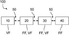
- FIG. 1illustrates a schematic view of a platoon
- FIG. 2illustrates a schematic view of a following vehicle and a preceding vehicle
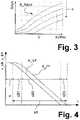
- FIG. 3illustrates exemplary distance curves for determining a dynamic vehicle distance
- FIG. 4illustrates a time graph of a following vehicle deceleration and a preceding vehicle deceleration in the case that an emergency braking procedure has been performed
- FIG. 5illustrates a flow diagram of a method according to an embodiment of the invention.
- Embodiments of the inventionpropose methods for determining a dynamic vehicle distance, wherein in a simple manner a vehicle distance may be determined that fulfills both the requirements relating to safety during a possible emergency braking procedure and that also optimizes the fuel consumption and the road capacity utilization. Furthermore, embodiments of the invention provide control units for performing such methods.
- a current transmission distanceis defined in this case as the distance that the following vehicle travels until the information that the preceding vehicle has initiated an emergency braking procedure is received by the following vehicle and said following vehicle likewise initiates an emergency brake system in response thereto.
- the braking distance differenceis formed from the difference between a preceding vehicle braking distance and a following vehicle braking distance if during an emergency braking situation the two vehicles each brake with a maximum preceding vehicle deceleration or rather a maximum following vehicle deceleration.
- a current transmission timein particular is determined in accordance with the invention and furthermore the current maximum preceding vehicle deceleration of the preceding vehicle and the current maximum following vehicle deceleration of the following vehicle are determined in order for the procedure of calculating the dynamic vehicle distance to be able to advantageously use the actually prevailing values.
- the current transmission timeindicates in this case the time that is actually required to transmit information between the preceding vehicle and the following vehicle, in other words the time between sending information, by way of example that an emergency braking procedure has been initiated, on the preceding vehicle and receiving this information on the following vehicle.
- the preceding vehiclecommunicates in this case with the following vehicle and conversely via a wireless data communication or rather vehicle-to-vehicle communication (V2V), which renders it possible for V2V signals to be exchanged in a wireless manner in order to be able to transmit information in a simple manner between the vehicles, said communication procedures rendering it possible in particular to monitor and coordinate the platoon.
- V2Vvehicle-to-vehicle communication
- the current transmission distanceis then obtained from the determined current transmission time, preferably by taking into consideration a dead time, in other words the time it takes for processing the determined V2V signals and for outputting a braking request on the following vehicle, and from a response time, in other words the time after which the braking request is output until a braking pressure is actually built up at the brakes of the following vehicle.
- the transmission distanceindicates the distance traveled by the following vehicle between the preceding vehicle initiating a braking procedure and the following vehicle initiating an emergency braking procedure.
- the braking distance differenceis determined accordingly from the difference between the braking distances for the currently determined maximum preceding vehicle deceleration and the current maximum following vehicle deceleration, wherein it is possible to use for this purpose a deceleration difference between the maximum preceding vehicle deceleration and the maximum following vehicle deceleration.
- the procedure of determining the dynamic vehicle distanceuses current additional information, in other words in particular uses a current transmission time and a current maximum vehicle deceleration and does not use values that have been previously fixedly parameterized or rather fixedly stored. As a consequence, it is possible to determine a vehicle distance that is dynamically adjusted to the current driving situation.
- the vehicle distanceis advantageously adjusted in such a manner that in the case of an emergency braking procedure that is initiated by the preceding vehicle with the maximum preceding vehicle deceleration, the following vehicle that likewise initiates an emergency braking procedure with the maximum following vehicle deceleration comes to a standstill in such a manner that a rear-end collision does not occur.
- the dynamic vehicle distanceis set in such a manner that it is possible to reduce the fuel consumption and the road capacity utilization is optimized. It is consequently possible to take the two aspects into consideration.
- the dynamic vehicle distanceis obtained in this case advantageously from a distance curve that is stored in the following vehicle, by way of example in a control unit in accordance with the invention, wherein said distance curve indicates for a determined transmission distance the connection between the deceleration difference and the dynamic vehicle distance. If therefore the deceleration difference between the maximum preceding vehicle deceleration and the maximum following vehicle deceleration is known, it is possible to read out the dynamic vehicle distance from the corresponding distance curve for the determined transmission distance.
- the maximum preceding vehicle deceleration of the preceding vehiclemay be transmitted via the V2V signal from the preceding vehicle to the following vehicle.
- the preceding vehicledetermines by way of example in a previously performed test braking procedure with full deceleration the maximum preceding vehicle deceleration that is to be achieved and is dependent by way of example upon a current preceding vehicle friction value, a current preceding vehicle brake lining condition, a current preceding vehicle braking response behavior, a current preceding vehicle tire condition, a current preceding vehicle brake condition or is also dependent upon the weather, and transmits this maximum preceding vehicle deceleration that is to be achieved in a wireless manner via the V2V signal via the wireless data communication to the following vehicle.
- the maximum preceding vehicle deceleration that is to be achievedmay also be adjusted while the vehicle is traveling, by way of example in dependence upon a current braking temperature.
- the following vehiclemay then determine therefrom the dynamic vehicle distance using the relevant maximum following vehicle deceleration.
- the maximum following vehicle decelerationis obtained in this case by way of example in a similar manner to that for the preceding vehicle from previously performed test braking procedures with full deceleration, where necessary adjusted to the braking temperature.
- customary valuesmay be assumed as current in order to be able to safely adjust the vehicle distance advantageously at least for a worst-case-scenario.
- a first transmission timeis determined advantageously via a time stamp that comprises a sent time at which the V2V signal has been sent by the preceding vehicle and a receiving time at which the V2V signal is received by the following vehicle.
- a location stampmay also be used in order to ensure that it concerns the respective preceding vehicle.
- the current transmission timein a safe and simple manner since the time stamp is in any case transmitted.
- the information regarding an emergency braking procedure that is initiated by the preceding vehicleis transmitted to the following vehicle via the V2V signal.
- the procedure of determining the first transmission timemay in this case be performed for each desired transmitted V2V signal since a wireless data exchange is in any case constantly taking place.
- the wireless data communicationmay fail, it is possible to assume as a current transmission time a customary value that is determined by redundancy systems, wherein possible redundancy systems are by way of example a VLC light source and/or a distance sensor system. Accordingly, a second transmission time or a third transmission time may be assumed in lieu of the first transmission time.
- the preceding vehiclemay transmit by way of example via a VLC light source the information that an emergency braking procedure has been initiated. In other words, information is transmitted using light (visible light communication), wherein the VLC light source outputs for this purpose an optical warning signal in the visible spectrum if an emergency braking procedure is initiated by the preceding vehicle.
- the second transmission timeis assumed, in other words the time until the following vehicle is able to initiate an emergency braking procedure at the earliest after the preceding vehicle.
- the dynamic vehicle status or rather the transmission distanceis then determined in dependence upon this second transmission time and also upon the dead time and the response time.
- the third transmission timeis assumed in addition to the dead time and the response time for determining the transmission distance, wherein the third transmission time characterizes the time for a distance sensor system to detect a changing relative velocity. In other words, a check is performed using the distance sensor system as to whether the preceding vehicle has initiated an emergency braking procedure and based thereon initiate an emergency braking procedure according to the third transmission time.
- the braking distance differenceis then preferably determined using the last known values for the maximum preceding vehicle deceleration and the following vehicle deceleration if it is no longer possible to receive a V2V signal in a wireless manner.
- FIG. 1illustrates a platoon 100 in which a plurality of vehicles 10 , 20 , 30 , 40 , preferably passenger cars and/or commercial vehicles, in particular semitrailers or trucks with trailers, are driving one behind the other.
- the vehicles 20 , 30 , 40are following vehicles FF and the vehicles 10 , 20 , 30 are preceding vehicles VF, wherein a following vehicle FF follows a preceding vehicle VF, which is driving in front of said following vehicle, at a determined dynamic vehicle distance Adyn in accordance with FIG. 2 , wherein the dynamic vehicle distance Adyn indicates a spatial distance.
- the dynamic vehicle distance Adyn between the following vehicle FF and the respective preceding vehicle VFmay vary since it is provided to dynamically set a lowest-possible safe vehicle distance Adyn with respect to the preceding vehicle VF, in other words adjusted to the respective driving situation of the relevant vehicles 10 , 20 , 30 , 40 .
- the dynamic vehicle distance Adynis selected in such a manner that a collision between the vehicles 10 , 20 , 30 , 40 may also be prevented in the case of an emergency braking procedure N of the preceding vehicle VF in a dangerous situation. Furthermore, the dynamic vehicle distance Adyn is selected in such a manner that it is possible to optimize fuel consumption and road capacity utilization.
- a V2V signal S 1is constantly transmitted between the preceding vehicle VF and the respective following vehicle FF via a wireless data communication 50 (vehicle-to-vehicle communication, V2V) so as to be able to coordinate or rather monitor the platoon 100 .
- the V2V signal S 1transmits in this case in particular a vehicle velocity v_VF, vFF of the respective vehicles VF, FF, the dynamic vehicle distance Adyn and also the information regarding whether an emergency braking procedure N has been initiated.
- a V2V signal S 1is transmitted within a first transmission time t 1 exclusively in a wireless manner.
- the dynamic vehicle distance Adynis determined by each following vehicle FF itself, wherein said distance is selected in such a manner that in the case of an emergency braking procedure N of the following vehicle FF with a maximum possible following vehicle deceleration zMax_FF for the following vehicle FF, it is possible to avoid a collision with the preceding vehicle VF that has initiated an emergency braking procedure N with a maximum possible preceding vehicle deceleration zMax_VF for the preceding vehicle VF.
- the dynamic vehicle distance Adyncomprises for this purpose a transmission distance s and a braking distance difference sB.
- the transmission distance sindicates in this case the distance that the following vehicle FF travels between the point in time t at which the preceding vehicle VF starts to brake and the point in time t at which the following vehicle FF starts to brake, in other words the distance that is required to transmit the information to the following vehicle FF that the preceding vehicle VF has initiated an emergency braking procedure N and it is necessary for the following vehicle FF to implement an emergency braking procedure N.
- the transmission distance sis in this case by way of example dependent upon the first transmission time t 1 for transmitting the V2V signal S 1 and also upon a dead time tT and a response time tS, wherein the dead time tT indicates the time for processing the transmitted V2V signals S 1 on the following vehicle FF until a braking request is output and the response time tS indicates the time starting with the output of a braking request until a braking pressure is actually built up.
- the preceding vehicle VFmay in the case of an emergency braking procedure N brake more intensely than the following vehicle FF, it is necessary to select a greater vehicle distance Adyn than in the reverse case, so that a rear-end collision may be reliably avoided.
- Adyns+sB (dzMax).
- the dynamic vehicle distance Adynis plotted in dependence upon different transmission distances s over the deceleration difference dzMax in FIG. 3 in different distance curves K_Adyn, wherein the broken-line arrow indicates that the transmission distance s drops off in this direction for the respective distance curves K_Adyn, in other words the shorter the transmission distance s the shorter also the dynamic vehicle distance Adyn. Consequently, it follows from these distance curves K_Adyn how high the dynamic vehicle distance Adyn is to be selected in the case of a determined transmission distance s in dependence upon the determined maximum following vehicle deceleration zMax_FF and upon the maximum preceding vehicle deceleration zMax_VF.
- Distance curves K_A of this typemay be stored by way of example in dependence upon the velocity in the following vehicle FF with the result that it is possible in dependence upon the known values for the maximum following vehicle deceleration zMax_FF, the maximum preceding vehicle deceleration zMax_VF and upon the transmission distance s to determine the dynamic distance Adyn in the following vehicle FF.
- the actual or rather current maximum following vehicle deceleration zMax_FF of the following vehicle FFis obtained from the physical driving states of the following vehicle FF and may be determined by way of example in the previously performed test braking procedures with maximum deceleration by the following vehicle FF.
- the maximum following vehicle deceleration zMax_FFis in this case by way of example dependent upon a current following vehicle friction value mue_FF, a current following vehicle brake lining condition ZB_FF, a current following vehicle braking response behavior VB_FF or other current vehicle parameters that indicate the braking performance of the respective following vehicle FF.
- the first transmission time t 1is currently determined that in the normal operation of a platoon 100 may be assumed as time for a data transmission in order to transmit in particular the information regarding an initiated emergency braking procedure N.
- a precise time offset between a possible start of the emergency braking procedure N in the preceding vehicle VF and a possible start of the emergency braking procedure N in the following vehicle FFis obtained from the actual first transmission time t 1 by taking into consideration the dead time tT and the response time tS.
- an actual value for the transmission distance s (t 1 , tT, tS)is obtained therefrom, in other words the distance that the following vehicle FF travels in this actual first transmission time t 1 by taking into account a dead time tT and a response time tS.
- an actual or rather current maximum preceding vehicle deceleration zMax_VFis also determined in not to have to assume the value that has been adjusted for the worst-case-scenario.
- the respective preceding vehicle VFdetermines by the respective preceding vehicle VF in a similar manner to that also by the following vehicle FF, by way of example in test braking procedures with full deceleration, how intense or rather with which maximum preceding vehicle deceleration zMax_VF the respective preceding vehicle VF is actually able to brake in an emergency braking situation N. From the moment in time that the respective preceding vehicle VF joins the platoon 100 , this determined maximum preceding vehicle deceleration zMax_VF is constantly output via the V2V signal S 1 and consequently transmitted to the other following vehicles FF of the platoon 100 .
- the respective following vehicle FFmay then using the braking performance zMax_FF, zMax_VF that is currently established for the relevant following vehicle FF and currently established by the preceding vehicle VF determine the braking distance difference sB from the deceleration difference dzMax for the corresponding transmission distance s in accordance with FIG. 3 .
- the dynamic vehicle distance Adynis represented for a transmission distance s by way of example in FIG. 4 with the aid of velocity graphs K_VF, K_FF, wherein the respective braking distance w_VF, w_FF is obtained using an integration method from the respective velocity graph K_VF, KFF.
- the maximum preceding vehicle deceleration zMax_VFis equal to the maximum following vehicle deceleration zMax_FF, by way of example in each case 5 m/s 2 since the velocity graphs K_VF, K_FF have the same maximum positive gradient.
- the velocity graphs K_VF, K_FF or rather braking distance difference sBwhich is obtained using an integration method from the velocity graphs K_VF, K_FF or their difference may be divided into different partial braking distances sB 1 , sB 2 , sB 3 :
- a first partial braking distance sB 1indicates in this case the distance that the following vehicle FF travels after the transmission distance s until the preceding vehicle VF and the following vehicle FF have a constant preceding vehicle deceleration z_VF or rather a constant following vehicle deceleration z_FF, wherein these constant decelerations z_VF, z_FF in each case are predetermined by means of the maximum preceding vehicle deceleration zMax_VF or rather the maximum following vehicle deceleration zMax_FF.
- a second partial braking distance sB 2indicates the distance that the following vehicle FF travels while both the preceding vehicle VF and also the following vehicle FF brake constantly with the maximum preceding vehicle deceleration zMax_VF or rather the maximum following vehicle deceleration zMax_FF.
- a third partial braking distance sB 3indicates in this exemplary embodiment the distance that the following vehicle FF travels from the point in time t after which the preceding vehicle VF is at a standstill until the point in time t at which the following vehicle FF (after the start of the braking procedure) achieves the same velocity as the preceding vehicle VF.
- the dynamic vehicle distance Adynis consequently established in such a manner that in the case of a braking procedure of the following vehicle FF with the respective partial braking distances sB 1 , sB 2 , sB 3 , contact is not made with the preceding vehicle VF, in this respect also the transmission distance s is also taken into consideration.
- the preceding vehicle VFmay also output via a VLC light source 60 an optical warning signal SW to the following vehicle FF, wherein the VLC light source 60 represents a redundancy system for wireless transmission.
- the VLC light source 60represents a redundancy system for wireless transmission.
- informationis transmitted from the preceding vehicle VF to the following vehicle FF using light (visible light communication), wherein the VLC light source 60 outputs for this purpose the optical warning signal SW in the visible spectrum if an emergency braking procedure N is initiated by the preceding vehicle VF.
- the following vehicle FFconstantly records whether the VLC light source 60 outputs a warning signal SW and in the presence of the optical warning signal SW forwards a request for an emergency braking procedure N to be performed by way of example in the event that it is not possible to detect a V2V signal S 1 .
- the dynamic vehicle distance Adynis subsequently determined using a transmission distance s for which a second transmission time t 2 is assumed that takes into consideration the generation and detection of the warning signal SW.
- the last value transmitted via the V2V signal S 1is assumed as the maximum preceding vehicle deceleration zMax_VF. If this is not known, then customary values for a worst-case-scenario are used. As a consequence, it is possible to detect any failure of the wireless data communication 50 and an emergency braking procedure N of the preceding vehicle VF may be detected via the optical warning signal SW.
- a distance sensor system 70by way of example RADAR, LIDAR, camera braking light detection system, which represent a further redundancy system, to detect how high a change of a relative velocity dvRel is between the following vehicle FF and the preceding vehicle VF.
- the dynamic vehicle distance Adynis subsequently determined using a transmission distance s for which a third transmission time t 3 is assumed that takes into consideration the detection of the change in the relative velocity dvRel via the distance sensor system 70 .
- the value last transmitted via the V2V signal S 1is assumed as the maximum preceding vehicle deceleration zMax_VF.
- a dynamic vehicle distance Adynhas been determined in the following vehicle FF, this is set by controlling a brake system 80 and/or controlling a drive system 90 of the following vehicle FF in order to control the following vehicle FF safely in the platoon 100 .
- a distancemay be determined and set in accordance with a method in accordance with the invention as follows.
- an initial step St 0the method starts by way of example after the following vehicle FF joins a platoon 100 .
- a relevant maximum following vehicle deceleration zMax_FFis determined from physical driving conditions of the relevant following vehicle FF, which may be determined by way of example in previously performed test braking procedures with full deceleration by the following vehicle FF.
- a first transmission time t 1is determined from the data transmission via the V2V signal S 1 by taking into consideration the sent time to at which the V2V signal S 1 has been sent by the preceding vehicle VF, and the received time tE at which the relevant following vehicle FF has received the V2V signal S 1 . If the data transmission is disturbed, the second transmission time t 2 is used when the VLC warning light 60 is used or the third transmission time t 3 is used when the distance sensor system 70 is used, as described above.
- a third step St 3the maximum preceding vehicle deceleration zMax_VF that is determined by the preceding vehicle VF and transmitted via the V2V signal S 1 is recorded, which may be determined by way of example in previously performed test braking procedures with full deceleration by the preceding vehicle VF.
- the dynamic vehicle distance Adynmay be set by means of controlling the brakes and/or the drive of the following vehicle FF in order to increase the safety in the platoon 100 while simultaneously reducing fuel consumption.
- the dynamic vehicle distance Adynmay be set by means of controlling the brakes and/or the drive of the following vehicle FF in order to increase the safety in the platoon 100 while simultaneously reducing fuel consumption.
- the recitation of “at least one of A, B and C”should be interpreted as one or more of a group of elements consisting of A, B and C, and should not be interpreted as requiring at least one of each of the listed elements A, B and C, regardless of whether A, B and C are related as categories or otherwise.
- the recitation of “A, B and/or C” or “at least one of A, B or C”should be interpreted as including any singular entity from the listed elements, e.g., A, any subset from the listed elements, e.g., A and B, or the entire list of elements A, B and C.
Landscapes
- Engineering & Computer Science (AREA)
- Physics & Mathematics (AREA)
- General Physics & Mathematics (AREA)
- Automation & Control Theory (AREA)
- Transportation (AREA)
- Mechanical Engineering (AREA)
- Computer Networks & Wireless Communication (AREA)
- Signal Processing (AREA)
- Aviation & Aerospace Engineering (AREA)
- Radar, Positioning & Navigation (AREA)
- Remote Sensing (AREA)
- Traffic Control Systems (AREA)
- Control Of Driving Devices And Active Controlling Of Vehicle (AREA)
- Regulating Braking Force (AREA)
Abstract
Description
- 10,20,30,40 Vehicles of the platoon
- 50 Wireless data communication
- 60 VLC light source
- 70 Distance sensor system
- 80 Brake system
- 90 Drive system
- 100 Platoon
- Adyn Dynamic distance
- dvRel Relative velocity
- dzMax Deceleration difference
- FF Following vehicle
- K_FF Velocity graph of the following vehicle
- K_VF Velocity graph of the preceding vehicle
- mue_FF Following vehicle friction value
- mue_VF Preceding vehicle friction value
- N Emergency braking procedure
- t Point in time
- t1 First transmission time (V2V)
- t2 Second transmission time (VLC)
- t3 Third transmission time (Distance sensor system)
- tA Sent time
- tE Received time
- tT Dead time
- tS Response time
- S1 V2V signal
- s Transmission distance
- sB Braking distance difference
- sB1, sB2, sB3 Partial braking distances
- sW Warning signal
- v_FF Following vehicle velocity
- v_VF Preceding vehicle velocity
- VB_FF Following vehicle braking response behavior
- VB_VF Preceding vehicle braking response behavior
- VF Preceding vehicle
- W Weather
- w_FF Following vehicle braking distance
- w_VF Preceding vehicle braking distance
- ZB_FF Following vehicle brake lining condition
- ZB_VF Preceding vehicle brake lining condition
- z_FF Following vehicle deceleration
- zMax_FF Maximum vehicle deceleration of the following vehicle
- zMax_VF Maximum vehicle deceleration of the preceding vehicle
- z_VF Preceding vehicle deceleration
- St0, St1, St2, St3, St4 Steps of a method
Claims (13)
Applications Claiming Priority (3)
| Application Number | Priority Date | Filing Date | Title |
|---|---|---|---|
| DE102016011325.1ADE102016011325A1 (en) | 2016-09-21 | 2016-09-21 | A method for determining a dynamic vehicle distance between a follower vehicle and a front vehicle of a platoon |
| DE102016011325.1 | 2016-09-21 | ||
| PCT/EP2017/001002WO2018054520A1 (en) | 2016-09-21 | 2017-08-22 | Method for determining a dynamic vehicle distance between a following vehicle and a preceding vehicle of a platoon |
Publications (2)
| Publication Number | Publication Date |
|---|---|
| US20190232962A1 US20190232962A1 (en) | 2019-08-01 |
| US11318940B2true US11318940B2 (en) | 2022-05-03 |
Family
ID=59895260
Family Applications (1)
| Application Number | Title | Priority Date | Filing Date |
|---|---|---|---|
| US16/334,758Active2038-01-20US11318940B2 (en) | 2016-09-21 | 2017-08-22 | Method for determining a dynamic vehicle distance between a following vehicle and a preceding vehicle of a platoon |
Country Status (7)
| Country | Link |
|---|---|
| US (1) | US11318940B2 (en) |
| EP (1) | EP3516638B1 (en) |
| JP (1) | JP7066687B2 (en) |
| KR (1) | KR20190050792A (en) |
| CN (1) | CN109690642A (en) |
| DE (1) | DE102016011325A1 (en) |
| WO (1) | WO2018054520A1 (en) |
Cited By (1)
| Publication number | Priority date | Publication date | Assignee | Title |
|---|---|---|---|---|
| US12194997B2 (en) | 2019-11-08 | 2025-01-14 | Zf Cv Systems Global Gmbh | Method for controlling a vehicle and distance regulation control device |
Families Citing this family (49)
| Publication number | Priority date | Publication date | Assignee | Title |
|---|---|---|---|---|
| US9582006B2 (en) | 2011-07-06 | 2017-02-28 | Peloton Technology, Inc. | Systems and methods for semi-autonomous convoying of vehicles |
| US10520581B2 (en) | 2011-07-06 | 2019-12-31 | Peloton Technology, Inc. | Sensor fusion for autonomous or partially autonomous vehicle control |
| US20170242443A1 (en) | 2015-11-02 | 2017-08-24 | Peloton Technology, Inc. | Gap measurement for vehicle convoying |
| WO2018039114A1 (en) | 2016-08-22 | 2018-03-01 | Peloton Technology, Inc. | Systems for vehicular platooning and methods therefor |
| US10520952B1 (en) | 2011-07-06 | 2019-12-31 | Peloton Technology, Inc. | Devices, systems, and methods for transmitting vehicle data |
| US11334092B2 (en) | 2011-07-06 | 2022-05-17 | Peloton Technology, Inc. | Devices, systems, and methods for transmitting vehicle data |
| US11294396B2 (en) | 2013-03-15 | 2022-04-05 | Peloton Technology, Inc. | System and method for implementing pre-cognition braking and/or avoiding or mitigation risks among platooning vehicles |
| US20180210463A1 (en) | 2013-03-15 | 2018-07-26 | Peloton Technology, Inc. | System and method for implementing pre-cognition braking and/or avoiding or mitigation risks among platooning vehicles |
| JP7005526B2 (en) | 2016-05-31 | 2022-01-21 | ぺロトン テクノロジー インコーポレイテッド | State machine of platooning controller |
| US10369998B2 (en) | 2016-08-22 | 2019-08-06 | Peloton Technology, Inc. | Dynamic gap control for automated driving |
| FR3076047B1 (en)* | 2017-12-22 | 2021-01-08 | Michelin & Cie | PROCESS FOR MANAGING A PLATOON OF TRUCKS BASED ON INFORMATION RELATING TO THE TIRES EQUIPPING THE TRUCKS DUDIT PLATOON |
| FR3078786A1 (en)* | 2018-03-08 | 2019-09-13 | Orange | METHOD FOR ADAPTING THE SPEED OF VEHICLES MOVING INTO CONVOY |
| CN108556845B (en)* | 2018-04-10 | 2020-07-10 | 清华大学 | A vehicle following system and method |
| DE102018206446A1 (en)* | 2018-04-26 | 2019-10-31 | Zf Friedrichshafen Ag | Method and control device for adjusting the distance between platoon vehicles |
| DE102018206569B4 (en)* | 2018-04-27 | 2022-08-04 | Bayerische Motoren Werke Aktiengesellschaft | System and method for operating an autonomous drawbarless trailer |
| JP7180126B2 (en)* | 2018-06-01 | 2022-11-30 | 株式会社デンソー | travel control device |
| US10899323B2 (en) | 2018-07-08 | 2021-01-26 | Peloton Technology, Inc. | Devices, systems, and methods for vehicle braking |
| DE102018118744A1 (en)* | 2018-08-02 | 2020-02-06 | Wabco Gmbh | Method for setting a vehicle deceleration of a vehicle in a platoon, and platooning control system and vehicle |
| US10887023B1 (en) | 2018-10-10 | 2021-01-05 | Wayfarer, Inc. | Variable bandwidth free-space optical communication system for autonomous or semi-autonomous passenger vehicles |
| US10762791B2 (en) | 2018-10-29 | 2020-09-01 | Peloton Technology, Inc. | Systems and methods for managing communications between vehicles |
| KR102610741B1 (en)* | 2018-11-15 | 2023-12-08 | 현대자동차주식회사 | Apparatus for controlling platooning of vehicle and method thereof |
| US11709501B2 (en)* | 2019-02-14 | 2023-07-25 | Toyota Motor North America, Inc. | System and method for controlling an autonomous vehicle |
| JP7379462B2 (en)* | 2019-03-15 | 2023-11-14 | 本田技研工業株式会社 | Vehicle communication device and program |
| US11427196B2 (en) | 2019-04-15 | 2022-08-30 | Peloton Technology, Inc. | Systems and methods for managing tractor-trailers |
| DE102019210559A1 (en)* | 2019-04-15 | 2020-10-15 | Technische Universität Dresden | Method for controlling a convoy by means of vehicle-to-vehicle communication |
| US11462111B2 (en) | 2019-04-29 | 2022-10-04 | Qualcomm Incorporated | Method and apparatus for vehicle maneuver planning and messaging |
| DE102019210664A1 (en)* | 2019-07-18 | 2021-01-21 | Robert Bosch Gmbh | Method for operating a vehicle in a vehicle group |
| CN110466520A (en)* | 2019-08-01 | 2019-11-19 | 武汉理工大学 | A kind of adaptive cruise method based on coefficient of road adhesion identification |
| JP7120186B2 (en)* | 2019-08-29 | 2022-08-17 | トヨタ自動車株式会社 | vehicle control system |
| EP3790295B1 (en)* | 2019-09-09 | 2024-05-29 | Volkswagen AG | Method, computer program, and apparatus for determining a minimum inter-vehicular distance for a platoon, vehicle, traffic control entity |
| EP3790296B1 (en) | 2019-09-09 | 2025-08-06 | Volkswagen AG | Method, computer program, and apparatus for adapting a speed of vehicles in a platoon, vehicle, traffic control entity |
| CN110861682A (en)* | 2019-11-13 | 2020-03-06 | 中国铁路兰州局集团有限公司 | Intelligent road condition measuring and controlling system for railway vehicle |
| CN110789576B (en)* | 2019-11-26 | 2021-09-10 | 交控科技股份有限公司 | Collaborative formation train safety protection scene division method and device |
| DE102019132943A1 (en)* | 2019-12-04 | 2021-06-10 | Wabco Europe Bvba | Method for coordinating vehicles in a vehicle group during emergency braking and a control unit |
| DE102020202513A1 (en) | 2020-02-27 | 2021-09-02 | Robert Bosch Gesellschaft mit beschränkter Haftung | Method for operating an automated vehicle group |
| CN111356076B (en)* | 2020-03-02 | 2025-07-08 | 腾讯科技(深圳)有限公司 | Message screening method and device |
| KR20210149973A (en)* | 2020-06-02 | 2021-12-10 | 현대모비스 주식회사 | Platoon driving control system and method of vehicle |
| EP4168281B1 (en)* | 2020-06-19 | 2025-05-21 | Glydways, Inc. | Braking and signaling schemes for autonomous vehicle system |
| KR20220005680A (en)* | 2020-07-06 | 2022-01-14 | 현대모비스 주식회사 | Platoon driving control system and method of vehicle |
| CN114003024B (en)* | 2020-07-13 | 2024-06-18 | 广州汽车集团股份有限公司 | A vehicle speed planning method, device and vehicle based on vehicle formation |
| WO2022103906A2 (en)* | 2020-11-12 | 2022-05-19 | Cummins Inc. | Systems and methods to use tire connectivity for powertrain efficiency |
| US11827245B2 (en)* | 2021-03-09 | 2023-11-28 | Toyota Motor Engineering & Manufacturing North America, Inc. | Systems and methods for estimating motion of an automated vehicle for cooperative driving |
| DE102021116468A1 (en) | 2021-06-25 | 2022-12-29 | Ford Global Technologies, Llc | Method for operating a vehicle platoon with a plurality of motor vehicles |
| US20230054327A1 (en)* | 2021-08-19 | 2023-02-23 | Toyota Research Institute, Inc. | Collaborative localization of a vehicle using radiolocation |
| US12427996B1 (en)* | 2021-09-27 | 2025-09-30 | Grote Industries, Inc. | Wireless vehicle communication system |
| CN114670830A (en)* | 2022-01-05 | 2022-06-28 | 天津卡尔狗科技有限公司 | Vehicle control method, apparatus, controller, storage medium, and program product |
| DE102022100289A1 (en) | 2022-01-07 | 2023-07-13 | Zf Cv Systems Global Gmbh | Method for determining the maximum possible braking deceleration of a vehicle and braking system for carrying out the method |
| KR20240150640A (en)* | 2023-04-06 | 2024-10-16 | 현대자동차주식회사 | Apparatus for controlling a vehicle, and method thereof |
| EP4542522A1 (en)* | 2023-10-16 | 2025-04-23 | Kopernikus Automotive GmbH | Method of operating a vehicle convoy, vehicle and system for coupling the movements of at least two vehicles |
Citations (21)
| Publication number | Priority date | Publication date | Assignee | Title |
|---|---|---|---|---|
| JPH09249047A (en) | 1996-03-18 | 1997-09-22 | Nissan Diesel Motor Co Ltd | Vehicle group traveling controller |
| JPH10293899A (en) | 1997-04-21 | 1998-11-04 | Fujitsu Ten Ltd | Device and method for controlling vehicle group formation |
| DE102004008895A1 (en) | 2004-02-24 | 2005-09-08 | Robert Bosch Gmbh | System for controlling and / or regulating driver assistance systems and method related thereto |
| US20070117525A1 (en)* | 2005-11-18 | 2007-05-24 | Hitachi, Ltd. | Method and apparatus for vehicle-to-vehicle multi-hop broadcast communication |
| JP2009043174A (en) | 2007-08-10 | 2009-02-26 | Sumitomo Electric Ind Ltd | Information providing apparatus and information providing method |
| JP2009090718A (en) | 2007-10-04 | 2009-04-30 | Denso Corp | Safety traveling system |
| US20090212935A1 (en) | 2008-02-24 | 2009-08-27 | Qi Luo | Anti-collision Emergency Braking System |
| DE102008026686A1 (en) | 2008-06-04 | 2009-12-10 | Andreas Glindemann | Method for simultaneously controlling acceleration of group of motor vehicles i.e. lorries, involves determining distances between motor vehicles and controlling acceleration of each motor vehicle |
| JP2010102522A (en) | 2008-10-24 | 2010-05-06 | Mitsubishi Electric Corp | Information providing device and information providing method |
| US20100256835A1 (en) | 2009-04-06 | 2010-10-07 | Gm Global Technology Operations, Inc. | Fail-safe speed profiles for cooperative autonomous vehicles |
| DE102010028637A1 (en) | 2010-05-05 | 2011-11-10 | Bayerische Motoren Werke Aktiengesellschaft | Coupling method for electronically coupling two motor vehicles, involves using vehicle property information for coupling of two vehicles, where vehicle property for one vehicle influences resulting aerodynamic drag for another vehicle |
| JP2012027862A (en) | 2010-07-27 | 2012-02-09 | Toyota Motor Corp | Vehicle control system |
| JP2012035817A (en) | 2010-08-11 | 2012-02-23 | Toyota Motor Corp | Vehicle control device |
| US20120191318A1 (en) | 2011-01-26 | 2012-07-26 | Audi Ag | Method for operating a longitudinal driver assist system of an automobile, and an automobile |
| JP2012256167A (en) | 2011-06-08 | 2012-12-27 | Japan Automobile Research Institute | Platooning control device |
| US20130041567A1 (en)* | 2011-08-10 | 2013-02-14 | Denso Corporation | Travel support apparatus and travel support system |
| DE102012002695A1 (en) | 2012-02-14 | 2013-08-14 | Wabco Gmbh | Method for determining an emergency braking situation of a vehicle |
| JP2014099098A (en) | 2012-11-15 | 2014-05-29 | Denso Corp | Communication device |
| DE102014223999A1 (en) | 2014-11-25 | 2016-05-25 | Bayerische Motoren Werke Aktiengesellschaft | Longitudinal driver assistance system of a motor vehicle with situation-dependent parameterization |
| WO2016134770A1 (en) | 2015-02-26 | 2016-09-01 | Volvo Truck Corporation | Method of controlling inter-vehicle gap(s) in a platoon |
| US10016895B2 (en)* | 2015-01-30 | 2018-07-10 | Kuka Deutschland Gmbh | Method and system for operating and/or monitoring a multi-axis machine |
Family Cites Families (7)
| Publication number | Priority date | Publication date | Assignee | Title |
|---|---|---|---|---|
| JP2004217175A (en)* | 2003-01-17 | 2004-08-05 | Toyota Motor Corp | Inter-vehicle distance control device |
| WO2005003885A2 (en)* | 2003-07-07 | 2005-01-13 | Sensomatix Ltd. | Traffic information system |
| DE102008014771A1 (en)* | 2008-03-18 | 2009-09-24 | Wabco Gmbh | Adaptive cruise control |
| CN102473350B (en)* | 2009-07-27 | 2014-04-16 | 丰田自动车株式会社 | Vehicular information processing device |
| CN104054119B (en)* | 2012-01-20 | 2016-08-24 | 丰田自动车株式会社 | Vehicle behavior prediction device, vehicle behavior prediction method, and driving support device |
| CN104859654B (en)* | 2015-05-12 | 2017-12-26 | 同济大学 | The real-time computing technique of limiting vehicle speed target range and with progress control method of speeding |
| CN105427669B (en)* | 2015-12-04 | 2019-05-31 | 重庆邮电大学 | A kind of anti-collision early warning method based on DSRC truck traffic technology |
- 2016
- 2016-09-21DEDE102016011325.1Apatent/DE102016011325A1/enactivePending
- 2017
- 2017-08-22USUS16/334,758patent/US11318940B2/enactiveActive
- 2017-08-22JPJP2019514819Apatent/JP7066687B2/enactiveActive
- 2017-08-22KRKR1020197008276Apatent/KR20190050792A/ennot_activeCeased
- 2017-08-22CNCN201780055186.2Apatent/CN109690642A/enactivePending
- 2017-08-22EPEP17768357.0Apatent/EP3516638B1/enactiveActive
- 2017-08-22WOPCT/EP2017/001002patent/WO2018054520A1/ennot_activeCeased
Patent Citations (28)
| Publication number | Priority date | Publication date | Assignee | Title |
|---|---|---|---|---|
| JPH09249047A (en) | 1996-03-18 | 1997-09-22 | Nissan Diesel Motor Co Ltd | Vehicle group traveling controller |
| JPH10293899A (en) | 1997-04-21 | 1998-11-04 | Fujitsu Ten Ltd | Device and method for controlling vehicle group formation |
| DE102004008895A1 (en) | 2004-02-24 | 2005-09-08 | Robert Bosch Gmbh | System for controlling and / or regulating driver assistance systems and method related thereto |
| US20070117525A1 (en)* | 2005-11-18 | 2007-05-24 | Hitachi, Ltd. | Method and apparatus for vehicle-to-vehicle multi-hop broadcast communication |
| JP2009043174A (en) | 2007-08-10 | 2009-02-26 | Sumitomo Electric Ind Ltd | Information providing apparatus and information providing method |
| JP2009090718A (en) | 2007-10-04 | 2009-04-30 | Denso Corp | Safety traveling system |
| US20090212935A1 (en) | 2008-02-24 | 2009-08-27 | Qi Luo | Anti-collision Emergency Braking System |
| DE102008026686A1 (en) | 2008-06-04 | 2009-12-10 | Andreas Glindemann | Method for simultaneously controlling acceleration of group of motor vehicles i.e. lorries, involves determining distances between motor vehicles and controlling acceleration of each motor vehicle |
| JP2010102522A (en) | 2008-10-24 | 2010-05-06 | Mitsubishi Electric Corp | Information providing device and information providing method |
| US20100256835A1 (en) | 2009-04-06 | 2010-10-07 | Gm Global Technology Operations, Inc. | Fail-safe speed profiles for cooperative autonomous vehicles |
| US20100256852A1 (en)* | 2009-04-06 | 2010-10-07 | Gm Global Technology Operations, Inc. | Platoon vehicle management |
| DE102010013647A1 (en) | 2009-04-06 | 2011-02-03 | GM Global Technology Operations, Inc., Detroit | Column vehicle management |
| DE102010028637A1 (en) | 2010-05-05 | 2011-11-10 | Bayerische Motoren Werke Aktiengesellschaft | Coupling method for electronically coupling two motor vehicles, involves using vehicle property information for coupling of two vehicles, where vehicle property for one vehicle influences resulting aerodynamic drag for another vehicle |
| JP2012027862A (en) | 2010-07-27 | 2012-02-09 | Toyota Motor Corp | Vehicle control system |
| US20130116861A1 (en) | 2010-07-27 | 2013-05-09 | Toyota Jidosha Kabushiki Kaisha | Vehicle control system |
| JP2012035817A (en) | 2010-08-11 | 2012-02-23 | Toyota Motor Corp | Vehicle control device |
| US20130144502A1 (en) | 2010-08-11 | 2013-06-06 | Toyota Jidosha Kabushiki Kaisha | Vehicle control device and vehicle control method |
| DE102011009483A1 (en) | 2011-01-26 | 2012-07-26 | Audi Ag | Method for operating a longitudinal driver assistance system of a motor vehicle and motor vehicle |
| US20120191318A1 (en) | 2011-01-26 | 2012-07-26 | Audi Ag | Method for operating a longitudinal driver assist system of an automobile, and an automobile |
| JP2012256167A (en) | 2011-06-08 | 2012-12-27 | Japan Automobile Research Institute | Platooning control device |
| US20130041567A1 (en)* | 2011-08-10 | 2013-02-14 | Denso Corporation | Travel support apparatus and travel support system |
| DE102012002695A1 (en) | 2012-02-14 | 2013-08-14 | Wabco Gmbh | Method for determining an emergency braking situation of a vehicle |
| US20150012204A1 (en) | 2012-02-14 | 2015-01-08 | Wabco Gmbh | Method for Determining an Emergency Braking Situation of a Vehicle |
| JP2014099098A (en) | 2012-11-15 | 2014-05-29 | Denso Corp | Communication device |
| DE102014223999A1 (en) | 2014-11-25 | 2016-05-25 | Bayerische Motoren Werke Aktiengesellschaft | Longitudinal driver assistance system of a motor vehicle with situation-dependent parameterization |
| US10016895B2 (en)* | 2015-01-30 | 2018-07-10 | Kuka Deutschland Gmbh | Method and system for operating and/or monitoring a multi-axis machine |
| WO2016134770A1 (en) | 2015-02-26 | 2016-09-01 | Volvo Truck Corporation | Method of controlling inter-vehicle gap(s) in a platoon |
| US20180126931A1 (en)* | 2015-02-26 | 2018-05-10 | Volvo Truck Corporaton | Method of controlling inter-vehicle gap(s) |
Cited By (1)
| Publication number | Priority date | Publication date | Assignee | Title |
|---|---|---|---|---|
| US12194997B2 (en) | 2019-11-08 | 2025-01-14 | Zf Cv Systems Global Gmbh | Method for controlling a vehicle and distance regulation control device |
Also Published As
| Publication number | Publication date |
|---|---|
| DE102016011325A1 (en) | 2018-03-22 |
| JP2019530086A (en) | 2019-10-17 |
| US20190232962A1 (en) | 2019-08-01 |
| EP3516638B1 (en) | 2024-01-24 |
| CN109690642A (en) | 2019-04-26 |
| JP7066687B2 (en) | 2022-05-13 |
| EP3516638A1 (en) | 2019-07-31 |
| WO2018054520A1 (en) | 2018-03-29 |
| KR20190050792A (en) | 2019-05-13 |
Similar Documents
| Publication | Publication Date | Title |
|---|---|---|
| US11318940B2 (en) | Method for determining a dynamic vehicle distance between a following vehicle and a preceding vehicle of a platoon | |
| US10234871B2 (en) | Distributed safety monitors for automated vehicles | |
| US10906544B2 (en) | Dynamic gap control for automated driving | |
| US10474166B2 (en) | System and method for implementing pre-cognition braking and/or avoiding or mitigation risks among platooning vehicles | |
| US11414060B2 (en) | Method and vehicle for activating an autonomous braking maneuver | |
| JPWO2018054520A5 (en) | ||
| CN103523016B (en) | Method for the operation vehicle during sliding | |
| KR101283073B1 (en) | Controlling apparatus for distance between cars, collision reduction and collision prevention and controlling method thereof | |
| US11577707B2 (en) | Systems and methods for braking in an autonomous vehicle | |
| US11328608B2 (en) | Method for controlling the braking of a following vehicle of a string comprising a plurality of platooning vehicles | |
| US11136029B2 (en) | Method for controlling a vehicle | |
| CN114746825A (en) | Method and control unit for coordinating vehicles of a vehicle combination | |
| JP2015022419A (en) | Convoy travel control device and convoy travel control method | |
| CN111055764A (en) | Logistics truck reversing and unloading auxiliary parking system and control method thereof | |
| US20220410923A1 (en) | Method for coordinating vehicles of a group of vehicles during emergency braking, and control unit | |
| JP2020091692A (en) | Platoon traveling controller | |
| JP7470655B2 (en) | Remote control device, remote automatic driving method, and computer program | |
| US20180178765A1 (en) | Brake assist system and method | |
| EP4300248B1 (en) | Method of controlling a platoon combination | |
| EP4136519B1 (en) | Method of controlling a platoon combination by exchanging brake performance estimation values | |
| US10279787B2 (en) | Method and device for carrying out a driver-independent brake force holding function in a motor vehicle when the motor vehicle is at a standstill on a roadway that is inclined in the vehicle longitudinal direction | |
| CN113492828A (en) | Vehicle control method and apparatus | |
| KR20230102465A (en) | Automatic emergency braking method and device considering road surface condition |
Legal Events
| Date | Code | Title | Description |
|---|---|---|---|
| FEPP | Fee payment procedure | Free format text:ENTITY STATUS SET TO UNDISCOUNTED (ORIGINAL EVENT CODE: BIG.); ENTITY STATUS OF PATENT OWNER: LARGE ENTITY | |
| AS | Assignment | Owner name:WABCO EUROPE BVBA, BELGIUM Free format text:ASSIGNMENT OF ASSIGNORS INTEREST;ASSIGNORS:BROLL, NIKLAS;DIECKMANN, THOMAS;WOLF, THOMAS;SIGNING DATES FROM 20190121 TO 20190128;REEL/FRAME:048749/0022 | |
| STPP | Information on status: patent application and granting procedure in general | Free format text:DOCKETED NEW CASE - READY FOR EXAMINATION | |
| STPP | Information on status: patent application and granting procedure in general | Free format text:NON FINAL ACTION MAILED | |
| STPP | Information on status: patent application and granting procedure in general | Free format text:RESPONSE TO NON-FINAL OFFICE ACTION ENTERED AND FORWARDED TO EXAMINER | |
| STPP | Information on status: patent application and granting procedure in general | Free format text:NON FINAL ACTION MAILED | |
| AS | Assignment | Owner name:ZF CV SYSTEMS EUROPE BV, BELGIUM Free format text:CHANGE OF NAME;ASSIGNOR:WABCO EUROPE BVBA;REEL/FRAME:056196/0042 Effective date:20210122 | |
| STPP | Information on status: patent application and granting procedure in general | Free format text:RESPONSE TO NON-FINAL OFFICE ACTION ENTERED AND FORWARDED TO EXAMINER | |
| STPP | Information on status: patent application and granting procedure in general | Free format text:FINAL REJECTION MAILED | |
| STPP | Information on status: patent application and granting procedure in general | Free format text:RESPONSE AFTER FINAL ACTION FORWARDED TO EXAMINER | |
| STPP | Information on status: patent application and granting procedure in general | Free format text:NOTICE OF ALLOWANCE MAILED -- APPLICATION RECEIVED IN OFFICE OF PUBLICATIONS | |
| STPP | Information on status: patent application and granting procedure in general | Free format text:PUBLICATIONS -- ISSUE FEE PAYMENT VERIFIED | |
| STCF | Information on status: patent grant | Free format text:PATENTED CASE |