US11318294B2 - Collapsible valve - Google Patents
Collapsible valveDownload PDFInfo
- Publication number
- US11318294B2 US11318294B2US16/299,003US201916299003AUS11318294B2US 11318294 B2US11318294 B2US 11318294B2US 201916299003 AUS201916299003 AUS 201916299003AUS 11318294 B2US11318294 B2US 11318294B2
- Authority
- US
- United States
- Prior art keywords
- valve
- housing
- concave cut
- access device
- head
- Prior art date
- Legal status (The legal status is an assumption and is not a legal conclusion. Google has not performed a legal analysis and makes no representation as to the accuracy of the status listed.)
- Active, expires
Links
- 238000000034methodMethods0.000claimsdescription20
- 239000012530fluidSubstances0.000claimsdescription14
- 239000007788liquidSubstances0.000claims10
- 238000013022ventingMethods0.000claims1
- 238000006073displacement reactionMethods0.000description9
- 230000008901benefitEffects0.000description7
- 238000004519manufacturing processMethods0.000description5
- 230000008569processEffects0.000description4
- 239000000463materialSubstances0.000description3
- 239000000203mixtureSubstances0.000description3
- 241000405070PercophidaeSpecies0.000description2
- 239000008280bloodSubstances0.000description2
- 210000004369bloodAnatomy0.000description2
- 238000003780insertionMethods0.000description2
- 230000037431insertionEffects0.000description2
- 238000000465mouldingMethods0.000description2
- 239000004033plasticSubstances0.000description2
- 238000007789sealingMethods0.000description2
- LFQSCWFLJHTTHZ-UHFFFAOYSA-NEthanolChemical compoundCCOLFQSCWFLJHTTHZ-UHFFFAOYSA-N0.000description1
- 238000004026adhesive bondingMethods0.000description1
- 230000004075alterationEffects0.000description1
- 238000010276constructionMethods0.000description1
- 230000001934delayEffects0.000description1
- 238000011010flushing procedureMethods0.000description1
- 230000005802health problemEffects0.000description1
- 230000008520organizationEffects0.000description1
- 239000004417polycarbonateSubstances0.000description1
- 229920000515polycarbonatePolymers0.000description1
- 229920001296polysiloxanePolymers0.000description1
- 238000006467substitution reactionMethods0.000description1
- 238000003466weldingMethods0.000description1
Images


Classifications
- A—HUMAN NECESSITIES
- A61—MEDICAL OR VETERINARY SCIENCE; HYGIENE
- A61M—DEVICES FOR INTRODUCING MEDIA INTO, OR ONTO, THE BODY; DEVICES FOR TRANSDUCING BODY MEDIA OR FOR TAKING MEDIA FROM THE BODY; DEVICES FOR PRODUCING OR ENDING SLEEP OR STUPOR
- A61M39/00—Tubes, tube connectors, tube couplings, valves, access sites or the like, specially adapted for medical use
- A61M39/10—Tube connectors; Tube couplings
- A—HUMAN NECESSITIES
- A61—MEDICAL OR VETERINARY SCIENCE; HYGIENE
- A61M—DEVICES FOR INTRODUCING MEDIA INTO, OR ONTO, THE BODY; DEVICES FOR TRANSDUCING BODY MEDIA OR FOR TAKING MEDIA FROM THE BODY; DEVICES FOR PRODUCING OR ENDING SLEEP OR STUPOR
- A61M39/00—Tubes, tube connectors, tube couplings, valves, access sites or the like, specially adapted for medical use
- A61M39/22—Valves or arrangement of valves
- A61M39/24—Check- or non-return valves
- A—HUMAN NECESSITIES
- A61—MEDICAL OR VETERINARY SCIENCE; HYGIENE
- A61M—DEVICES FOR INTRODUCING MEDIA INTO, OR ONTO, THE BODY; DEVICES FOR TRANSDUCING BODY MEDIA OR FOR TAKING MEDIA FROM THE BODY; DEVICES FOR PRODUCING OR ENDING SLEEP OR STUPOR
- A61M39/00—Tubes, tube connectors, tube couplings, valves, access sites or the like, specially adapted for medical use
- A61M39/22—Valves or arrangement of valves
- A61M39/26—Valves closing automatically on disconnecting the line and opening on reconnection thereof
- A—HUMAN NECESSITIES
- A61—MEDICAL OR VETERINARY SCIENCE; HYGIENE
- A61M—DEVICES FOR INTRODUCING MEDIA INTO, OR ONTO, THE BODY; DEVICES FOR TRANSDUCING BODY MEDIA OR FOR TAKING MEDIA FROM THE BODY; DEVICES FOR PRODUCING OR ENDING SLEEP OR STUPOR
- A61M39/00—Tubes, tube connectors, tube couplings, valves, access sites or the like, specially adapted for medical use
- A61M39/22—Valves or arrangement of valves
- A61M39/24—Check- or non-return valves
- A61M2039/2433—Valve comprising a resilient or deformable element, e.g. flap valve, deformable disc
- A—HUMAN NECESSITIES
- A61—MEDICAL OR VETERINARY SCIENCE; HYGIENE
- A61M—DEVICES FOR INTRODUCING MEDIA INTO, OR ONTO, THE BODY; DEVICES FOR TRANSDUCING BODY MEDIA OR FOR TAKING MEDIA FROM THE BODY; DEVICES FOR PRODUCING OR ENDING SLEEP OR STUPOR
- A61M39/00—Tubes, tube connectors, tube couplings, valves, access sites or the like, specially adapted for medical use
- A61M39/22—Valves or arrangement of valves
- A61M39/26—Valves closing automatically on disconnecting the line and opening on reconnection thereof
- A61M2039/263—Valves closing automatically on disconnecting the line and opening on reconnection thereof where the fluid space within the valve is decreasing upon disconnection
- A—HUMAN NECESSITIES
- A61—MEDICAL OR VETERINARY SCIENCE; HYGIENE
- A61M—DEVICES FOR INTRODUCING MEDIA INTO, OR ONTO, THE BODY; DEVICES FOR TRANSDUCING BODY MEDIA OR FOR TAKING MEDIA FROM THE BODY; DEVICES FOR PRODUCING OR ENDING SLEEP OR STUPOR
- A61M39/00—Tubes, tube connectors, tube couplings, valves, access sites or the like, specially adapted for medical use
- A61M39/22—Valves or arrangement of valves
- A61M39/26—Valves closing automatically on disconnecting the line and opening on reconnection thereof
- A61M2039/266—Valves closing automatically on disconnecting the line and opening on reconnection thereof where the valve comprises venting channels, e.g. to insure better connection, to help decreasing the fluid space upon disconnection, or to help the fluid space to remain the same during disconnection
- A—HUMAN NECESSITIES
- A61—MEDICAL OR VETERINARY SCIENCE; HYGIENE
- A61M—DEVICES FOR INTRODUCING MEDIA INTO, OR ONTO, THE BODY; DEVICES FOR TRANSDUCING BODY MEDIA OR FOR TAKING MEDIA FROM THE BODY; DEVICES FOR PRODUCING OR ENDING SLEEP OR STUPOR
- A61M2207/00—Methods of manufacture, assembly or production
- Y—GENERAL TAGGING OF NEW TECHNOLOGICAL DEVELOPMENTS; GENERAL TAGGING OF CROSS-SECTIONAL TECHNOLOGIES SPANNING OVER SEVERAL SECTIONS OF THE IPC; TECHNICAL SUBJECTS COVERED BY FORMER USPC CROSS-REFERENCE ART COLLECTIONS [XRACs] AND DIGESTS
- Y10—TECHNICAL SUBJECTS COVERED BY FORMER USPC
- Y10T—TECHNICAL SUBJECTS COVERED BY FORMER US CLASSIFICATION
- Y10T29/00—Metal working
- Y10T29/49—Method of mechanical manufacture
- Y10T29/49405—Valve or choke making
- Y—GENERAL TAGGING OF NEW TECHNOLOGICAL DEVELOPMENTS; GENERAL TAGGING OF CROSS-SECTIONAL TECHNOLOGIES SPANNING OVER SEVERAL SECTIONS OF THE IPC; TECHNICAL SUBJECTS COVERED BY FORMER USPC CROSS-REFERENCE ART COLLECTIONS [XRACs] AND DIGESTS
- Y10—TECHNICAL SUBJECTS COVERED BY FORMER USPC
- Y10T—TECHNICAL SUBJECTS COVERED BY FORMER US CLASSIFICATION
- Y10T29/00—Metal working
- Y10T29/49—Method of mechanical manufacture
- Y10T29/49826—Assembling or joining
Definitions
- the present disclosurerelates, generally, to fluid flow devices and, more specifically, to valves for use in medical devices.
- Needleless access devicesallow a healthcare professional to, e.g., replace/add IV bags, and/or access an IV line without having to use a needle.
- FIG. 1is a cut-away view of a current needleless access device 100 .
- Needleless access device 100includes female luer fitting 101 , male luer fitting 102 , and valve 103 .
- male luer fitting 102is connected to, e.g., a catheter or to a female luer
- female luer fitting 101is connected to a fluid reservoir.
- Female luer fitting 101is connected to the fluid reservoir via a second male luer fitting (not shown) that includes a hollow member inserted through the top of female luer fitting 101 , collapsing valve 103 down into volume 104 to break the seal and create a fluid flow path.
- the hollow member of the second male luer fittingdelivers the fluid, which flows around valve 103 into channels (not shown) in male luer fitting 102 and into the catheter or female luer.
- Device 100is a positive displacement device, so that when a new connection is made at female luer fitting 101 , device 100 pulls fluid in from the male side of the valve (i.e., the side proximate male luer fitting 102 ). When a disconnection is made at female luer fitting 101 , device 100 pushes fluid in from the female side (i.e., the side proximate the top of female luer fitting 101 .
- the advantage of positive displacementis that when a disconnection is made, device 100 expels fluid out of the male luer fitting 102 and effectively flushing the catheter.
- valve 103when the female end is accessed by a male luer (not shown), valve 103 is elastic so that it can bend out of the way to allow flow and then return to its original shape after a disconnection is made at the female end.
- device 100re-seals itself and forms a flat surface that can be disinfected at the top surface 110 using an alcohol swab.
- plastic valvesthat cannot flex to move out of the way to allow flow, thus requiring the use of valves that are slanted or incorporating features at the top, making swabbing difficult.
- Device 100has a symmetrical valve body providing symmetrical wall strength, as well as weakness points on both sides by virtue of duckbills 105 . Furthermore, device 100 includes uniform wall thickness in the valve body, even at and around duckbills 105 . The contact area between a luer and the top surface 110 of valve 103 and the type of luer motion will dictate the form of collapse of the valve body. Device 100 provides good performance, but could benefit from enhanced repeatability and controllability of collapse.
- Various embodiments of the inventionare directed to valves, and to needleless access devices that use collapsible valves, which include a cut and at least one dimple to cause specific collapsing valve behavior.
- a cutis placed on a top portion of a valve, the top portion being narrower in diameter than a bottom portion and forming the top seal of a needleless access device.
- the bottom portionis substantially cylindrical, forming a septum, and including at least one dimple thereon.
- the dimpleis angularly offset from the cut by approximately ninety degrees, enough so that a load point on the top surface of the valve is shifted away from the cut to delay the collapse of the cut and result in less forward fall of the top portion when the cut collapses.
- a method according to one embodimentis related to processes for manufacture of needleless access devices.
- Another embodimentis directed to a needleless access device that includes a collapsible valve.
- FIG. 1is a cut-away view of a current needleless access device
- FIGS. 2A and 2Bare cut-away views showing an exemplary needleless access device adapted according to one embodiment of the invention.
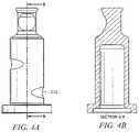
- FIGS. 3A-3Cshow views of a valve by itself
- FIGS. 4A and 4Bshow views ninety degrees from those of FIGS. 3A and 3B ;
- FIG. 5is an illustration of an exemplary needleless access device with a syringe inserted therein and collapsing an exemplary valve
- FIGS. 6A-6Dillustrate the behavior of an exemplary valve, as pressure is applied by a syringe, but before collapse, according to embodiments of the invention
- FIGS. 7A 7 Dillustrate behavior of an exemplary valve as pressure is applied by a syringe, but before collapse, according to embodiments of the invention
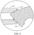
- FIG. 8is an illustration of one scenario of use of an exemplary valve.
- FIGS. 9A-9Cshow three examples of a wide variety of cuts that can be applied to some embodiments of the invention.
- FIGS. 2A and 2Bare cut-away views showing exemplary needleless access device 200 adapted according to one embodiment of the invention.
- the view in FIG. 2Bis rotated ninety degrees from that shown in FIG. 2A .
- Device 200includes female luer fitting 201 , male luer fitting 202 , and valve 210 .
- Valve 210includes cut 211 , which in this example, is referred to as a “smiley cut.”
- Valve 210also includes dimples 212 and 213 on the outside of its lower portion and placed with axial and angular offsets from each other so that the body of valve 210 is not symmetrical. While cut 211 is referred to as a cut, it can be manufactured using any of a variety of techniques, including molding so that a cut is not actually made.
- An example of a material that may be used for male and female luer fittings 201 and 202is polycarbonate, and an example of a material that may be used for valve 210 is silicone, though any of a variety of suitable materials may also be used in various embodiments.
- Device 200provides for positive displacement and self sealing, similar to the device shown in FIG. 1 .
- Male luer fitting 202 at the bottomconnects to a catheter or other medical device (not shown) that is connected to the body of the patient.
- a syringe(not shown) mates with female luer fitting 201 to collapse valve 210 into the cavity defined between male and female luer fittings 201 and 202 .
- Fluid flowgoes from the top of device 200 , around valve 210 , and through channels 230 , 240 to middle channel 250 of male luer fitting 202 .
- Valves 260 and 270allow air to enter and escape septum 215 of valve 210 .
- valve 210When closed, valve 210 provides two seals. The first seal is at the top surface 280 of device 200 . The second seal is at shoulder 290 . As explained in more detail with respect to FIG. 5 , insertion of a syringe at female luer fitting 201 collapses valve 210 , thereby breaking the seals. Valve 210 acts as a spring, so that when it is pushed it down, it collapses, and when the force is removed, it returns to its shape thereby resealing. Generally, the thicker the wall of valve 210 , the more spring force, and the thinner the wall, the less spring force. Therefore, wall thickness affects characteristics, such as ease of syringe insertion and displacement.
- valve 210is approximately two centimeters in length
- a wall thickness within the range of 0.030 and 0.038 inchesprovides acceptable displacement, sealing, and ease of use.
- the wall thicknessis less, as can be seen especially well at FIG. 3A .
- device 200is manufactured by separately molding valve 210 and male and female luer fittings 201 and 202 .
- Valve 210is then placed in the cavity that is formed by male and female luer fittings 201 and 202 .
- Male and female luer fittings 201 and 202are positioned and welded.
- Device 200is then sterilized and packaged.
- Other methods for manufacturingare possible, e.g., by gluing rather than welding male and female luers 201 and 202 , and are within the scope of embodiments.
- FIGS. 3A-Cshow views of valve 210 by itself.
- FIG. 3Bshows a side view
- FIG. 3Ashows a cut-away view
- FIG. 3Cshows a bottom view of valve 210 .
- both the top portion and the bottom portion of valve 210are annular (in this case, substantially cylindrically shaped), where the top portion includes smiley cut 211 , and the bottom portion includes dimples 212 and 213 .
- the bottom portion of valve 210is substantially hollow, defining septum 215 .
- FIGS. 4A and 4Bshow views ninety degrees from those of FIGS. 3A and 3B .
- FIG. 5is an illustration of exemplary device 200 with exemplary syringe 510 inserted therein and collapsing valve 210 .
- Smiley cut 211collapses, tilting its top surface 216 to let fluid flow out of syringe 510 .
- the lower portion of valve 210also collapses, aided by dimples 212 and 213 , which act as two weak points, placed to cause the lower portion to collapse before smiley cut 211 collapses.
- Arrowsare added to FIG. 5 to illustrate a path of fluid as it flows through syringe 510 , around valve 210 , and out of male luer 202 .
- FIGS. 6A-6Dillustrate the behavior of valve 210 , as pressure is applied by syringe 510 , but before collapse.
- dimple 213is placed ninety degrees clockwise from smiley cut 211 , which places load point 610 counterclockwise to smiley cut 211 (wherein clockwise and counterclockwise refer to the orientation shown in FIGS. 2-6 , where the valve 210 is shown with smiley cut 211 above the dimples).
- load point 610is notable because a male luer fitting (not shown) associated with syringe 510 has a thread to connect to female luer fitting 201 , thereby rotating syringe 510 as it is inserted (and in turn, putting rotational pressure on valve 210 ). As dimple 213 begins to collapse, pressure point 610 appears ninety degrees from smiley cut 211 , where the side of the top portion of valve 210 is stronger than it is directly above smiley cut 211 . In this embodiment, smiley cut 211 collapses later than it would in a scenario where load point 610 is placed directly over smiley cut 211 .
- FIGS. 7A-7Dillustrate behavior of valve 710 as pressure is applied by syringe 510 , but before collapse, according to embodiments of the invention.
- smiley cut 211is 180 degrees from dimple 213 and directly above dimple 212 .
- pressure point 720causes pressure point 720 to be directly above smiley cut 211 , thereby causing smiley cut 211 to collapse sooner than it does in the scenario illustrated in FIGS. 6A-6D .
- valve 210 and valve 710are acceptable alternatives.
- early collapse of smiley cut 211may cause the top of valve 710 to fall forward and become lodged in the counterbore, thereby somewhat impeding the flow of fluid.
- FIG. 8Such a scenario is shown in FIG. 8 , where the top of valve 710 is lodged in counterbore 820 of syringe 810 .
- valve 210delays the collapse of smiley cut 211 , providing a more vertical collapse of smiley cut 211 and avoiding blockage of syringe counterbores.
- valve 210can be employed successfully.
- valve 210 and valve 710can be successfully employed in applications using a syringe, such as that shown in FIGS. 5-7 .
- Various embodimentscan use any angular displacement of a dimple relative to a cut, with valve 210 and valve 710 illustrating two examples.
- valves 210 and 710are shown with two dimples each, various embodiments are not so limited. For instance, more dimples may be added, and some embodiments may include only one dimple. Furthermore, embodiments are not limited to the use of smiley cuts, as other shaped cuts may be employed. For instance, FIGS. 9A-9C show V-cut 910 , U-cut 920 , and “seagull” cut 930 , which are but three examples of a wide variety of cuts that can be applied to embodiments.
- valves 210 and 710 of the embodiments described aboveprovide positive displacement and are self-flushed, thereby providing better hygiene that negative displacement devices.
- the flat top surfaces of valves 210 and 710can provide for better swabability than do devices with slanted or grooved tops, once again providing better hygienic qualities.
- the dimples and cuts shown in the embodiments aboveprovide for somewhat predictable collapse of the valves, and (especially in the case of valve 210 ) applicability to any of a variety of syringes.
Landscapes
- Health & Medical Sciences (AREA)
- Heart & Thoracic Surgery (AREA)
- Pulmonology (AREA)
- Engineering & Computer Science (AREA)
- Anesthesiology (AREA)
- Biomedical Technology (AREA)
- Hematology (AREA)
- Life Sciences & Earth Sciences (AREA)
- Animal Behavior & Ethology (AREA)
- General Health & Medical Sciences (AREA)
- Public Health (AREA)
- Veterinary Medicine (AREA)
- Infusion, Injection, And Reservoir Apparatuses (AREA)
Abstract
Description
Claims (17)
Priority Applications (2)
| Application Number | Priority Date | Filing Date | Title |
|---|---|---|---|
| US16/299,003US11318294B2 (en) | 2009-07-30 | 2019-03-11 | Collapsible valve |
| US17/734,903US12285585B2 (en) | 2009-07-30 | 2022-05-02 | Collapsible valve |
Applications Claiming Priority (3)
| Application Number | Priority Date | Filing Date | Title |
|---|---|---|---|
| US12/512,719US8715247B2 (en) | 2009-07-30 | 2009-07-30 | Collapsible valve |
| US14/835,460US10265513B2 (en) | 2009-07-30 | 2015-08-25 | Collapsible valve |
| US16/299,003US11318294B2 (en) | 2009-07-30 | 2019-03-11 | Collapsible valve |
Related Parent Applications (1)
| Application Number | Title | Priority Date | Filing Date |
|---|---|---|---|
| US14/835,460ContinuationUS10265513B2 (en) | 2009-07-30 | 2015-08-25 | Collapsible valve |
Related Child Applications (1)
| Application Number | Title | Priority Date | Filing Date |
|---|---|---|---|
| US17/734,903ContinuationUS12285585B2 (en) | 2009-07-30 | 2022-05-02 | Collapsible valve |
Publications (2)
| Publication Number | Publication Date |
|---|---|
| US20190201682A1 US20190201682A1 (en) | 2019-07-04 |
| US11318294B2true US11318294B2 (en) | 2022-05-03 |
Family
ID=43527687
Family Applications (5)
| Application Number | Title | Priority Date | Filing Date |
|---|---|---|---|
| US12/512,719Active2029-09-25US8715247B2 (en) | 2009-07-30 | 2009-07-30 | Collapsible valve |
| US14/262,210ActiveUS9119950B2 (en) | 2009-07-30 | 2014-04-25 | Collapsible valve |
| US14/835,460ActiveUS10265513B2 (en) | 2009-07-30 | 2015-08-25 | Collapsible valve |
| US16/299,003Active2035-10-22US11318294B2 (en) | 2009-07-30 | 2019-03-11 | Collapsible valve |
| US17/734,903Active2030-05-29US12285585B2 (en) | 2009-07-30 | 2022-05-02 | Collapsible valve |
Family Applications Before (3)
| Application Number | Title | Priority Date | Filing Date |
|---|---|---|---|
| US12/512,719Active2029-09-25US8715247B2 (en) | 2009-07-30 | 2009-07-30 | Collapsible valve |
| US14/262,210ActiveUS9119950B2 (en) | 2009-07-30 | 2014-04-25 | Collapsible valve |
| US14/835,460ActiveUS10265513B2 (en) | 2009-07-30 | 2015-08-25 | Collapsible valve |
Family Applications After (1)
| Application Number | Title | Priority Date | Filing Date |
|---|---|---|---|
| US17/734,903Active2030-05-29US12285585B2 (en) | 2009-07-30 | 2022-05-02 | Collapsible valve |
Country Status (12)
| Country | Link |
|---|---|
| US (5) | US8715247B2 (en) |
| EP (3) | EP3747501A1 (en) |
| JP (1) | JP5695046B2 (en) |
| KR (1) | KR101749361B1 (en) |
| CN (1) | CN102497897B (en) |
| AU (1) | AU2010276758B2 (en) |
| BR (1) | BR112012001634B8 (en) |
| CA (2) | CA2993733C (en) |
| ES (2) | ES2733507T3 (en) |
| MX (1) | MX2012001117A (en) |
| RU (1) | RU2542776C2 (en) |
| WO (1) | WO2011014265A1 (en) |
Families Citing this family (48)
| Publication number | Priority date | Publication date | Assignee | Title |
|---|---|---|---|---|
| US6695817B1 (en) | 2000-07-11 | 2004-02-24 | Icu Medical, Inc. | Medical valve with positive flow characteristics |
| US7600530B2 (en) | 2004-08-09 | 2009-10-13 | Medegen, Inc. | Connector with check valve and method of use |
| US10478607B2 (en) | 2004-08-09 | 2019-11-19 | Carefusion 303, Inc. | Connector for transferring fluid and method of use |
| US20140276459A1 (en)* | 2013-03-13 | 2014-09-18 | Jonathan Yeh | Needleless connector with folding valve |
| US20060161115A1 (en) | 2004-11-05 | 2006-07-20 | Fangrow Thomas F | Soft-grip medical connector |
| US9168366B2 (en) | 2008-12-19 | 2015-10-27 | Icu Medical, Inc. | Medical connector with closeable luer connector |
| US8454579B2 (en) | 2009-03-25 | 2013-06-04 | Icu Medical, Inc. | Medical connector with automatic valves and volume regulator |
| US8715247B2 (en) | 2009-07-30 | 2014-05-06 | Carefusion 303, Inc. | Collapsible valve |
| US8323249B2 (en) | 2009-08-14 | 2012-12-04 | The Regents Of The University Of Michigan | Integrated vascular delivery system |
| US8636720B2 (en) | 2009-11-16 | 2014-01-28 | Carefusion 303, Inc. | Needleless access connectors and valve elements therefor |
| USD644731S1 (en) | 2010-03-23 | 2011-09-06 | Icu Medical, Inc. | Medical connector |
| US8298196B1 (en)* | 2010-03-24 | 2012-10-30 | Mansour George M | Needleless access connector and method of use |
| US8758306B2 (en) | 2010-05-17 | 2014-06-24 | Icu Medical, Inc. | Medical connectors and methods of use |
| US8814833B2 (en) | 2010-05-19 | 2014-08-26 | Tangent Medical Technologies Llc | Safety needle system operable with a medical device |
| WO2011146769A2 (en) | 2010-05-19 | 2011-11-24 | Tangent Medical Technologies Llc | Integrated vascular delivery system |
| TWI626063B (en)* | 2011-06-03 | 2018-06-11 | 凱爾福郡303股份有限公司 | Positive-displacement needleless access connector and method for manufacturing the same |
| US9067049B2 (en)* | 2011-07-25 | 2015-06-30 | Carefusion 303, Inc. | Providing positive displacement upon disconnection using a connector with a dual diaphragm valve |
| ES2664517T3 (en) | 2011-09-09 | 2018-04-19 | Icu Medical, Inc. | Medical connectors with fluid resistant coupling interfaces |
| JP5241045B2 (en)* | 2011-09-12 | 2013-07-17 | 信越ポリマー株式会社 | Connector valve body and connector |
| US8801678B2 (en) | 2012-01-20 | 2014-08-12 | Carefusion 303, Inc. | Piston for a needleless valve system |
| US9114244B2 (en) | 2012-01-27 | 2015-08-25 | Carefusion 303, Inc. | Needleless valve system fluid control |
| US9162029B2 (en)* | 2012-11-09 | 2015-10-20 | Carefusion 303, Inc. | Tailless needleless valve system |
| EP2916905A4 (en) | 2012-11-12 | 2016-11-09 | Icu Medical Inc | MEDICAL CONNECTION |
| CN103071200B (en)* | 2013-01-29 | 2014-02-26 | 苏州林华医疗器械有限公司 | Positive-pressure needle-free connecting piece |
| US9278205B2 (en) | 2013-03-13 | 2016-03-08 | Carefusion 303, Inc. | Collapsible valve with internal dimples |
| US9370651B2 (en)* | 2013-03-13 | 2016-06-21 | Carefusion 303, Inc. | Needleless connector with reduced trapped volume |
| US8840577B1 (en)* | 2013-03-14 | 2014-09-23 | Carefusion 303, Inc. | Needleless connector with flexible valve |
| US9144672B2 (en)* | 2013-03-13 | 2015-09-29 | Carefusion 303, Inc. | Needleless connector with compressible valve |
| US9089682B2 (en)* | 2013-03-14 | 2015-07-28 | Carefusion 303, Inc. | Needleless connector with support member |
| US8708976B1 (en)* | 2013-03-14 | 2014-04-29 | Carefusion 303, Inc. | Needleless connector with a tortuous fluid flow path |
| JP6370364B2 (en) | 2013-03-15 | 2018-08-08 | アイシーユー・メディカル・インコーポレーテッド | Medical connector |
| CN103272302B (en)* | 2013-05-15 | 2019-05-14 | 浙江康泰医疗器械有限公司 | Positive pressure connector |
| EP2862587A1 (en) | 2013-10-15 | 2015-04-22 | Becton Dickinson France | Tip cap assembly for closing an injection system |
| AU2014364218B2 (en) | 2013-12-11 | 2019-06-06 | Icu Medical, Inc. | Check valve |
| CA2937744C (en) | 2014-02-04 | 2022-08-09 | Icu Medical, Inc. | Self-priming systems and methods |
| CN106163608B (en) | 2014-03-26 | 2019-07-26 | 泰尔茂株式会社 | Connector and infusion set |
| EP3124073B1 (en)* | 2014-03-28 | 2019-01-30 | Terumo Kabushiki Kaisha | Medical connector |
| CN205252243U (en)* | 2014-08-08 | 2016-05-25 | 康尔福盛2200公司 | A washing port valve module for air flue adapter |
| USD793551S1 (en) | 2014-12-03 | 2017-08-01 | Icu Medical, Inc. | Fluid manifold |
| USD786427S1 (en) | 2014-12-03 | 2017-05-09 | Icu Medical, Inc. | Fluid manifold |
| ES3037643T3 (en) | 2016-07-11 | 2025-10-03 | Puracath Medical Inc | Point of care ultraviolet disinfection system |
| JP7102694B2 (en)* | 2017-09-15 | 2022-07-20 | 株式会社リコー | Complex and its manufacturing method, laminate, cell adhesion substrate and its manufacturing method |
| EP3941563A4 (en)* | 2019-03-22 | 2022-11-30 | Puracath Medical, Inc. | NEEDLELESS CONNECTOR VALVE FOR UV DISINFECTION |
| US12016961B2 (en) | 2019-10-04 | 2024-06-25 | Puracath Medical, Inc. | Point of care ultraviolet disinfection system |
| US11904131B2 (en)* | 2020-01-16 | 2024-02-20 | Carefusion 303, Inc. | Needleless connector having check valve with concave flow surface |
| US12036380B2 (en)* | 2021-05-04 | 2024-07-16 | Carefusion 303, Inc. | Needleless connector with compressible and deflectable valve |
| US11828388B2 (en) | 2022-03-08 | 2023-11-28 | B. Braun Medical Inc. | Needle-free connector |
| EP4623983A1 (en)* | 2022-11-24 | 2025-10-01 | Nipro Corporation | Needleless connector |
Citations (14)
| Publication number | Priority date | Publication date | Assignee | Title |
|---|---|---|---|---|
| CN1139010A (en) | 1995-06-23 | 1997-01-01 | 贝克顿迪金森公司 | Valved PRN adapter for medical access devices |
| US5730418A (en) | 1996-09-30 | 1998-03-24 | The Kipp Group | Minimum fluid displacement medical connector |
| US5782816A (en) | 1995-09-07 | 1998-07-21 | David R. Kipp | Bi-directional valve and method of using same |
| US20030098430A1 (en) | 2001-11-29 | 2003-05-29 | Leinsing Karl R. | Needle free medical connector with expanded valve mechanism and method of fluid flow control |
| US20030209681A1 (en) | 2002-05-08 | 2003-11-13 | Leinsing Karl R. | Needle-free medical connector with expandable valve mechanism and method of fluid flow control |
| US20050010177A1 (en) | 2003-07-08 | 2005-01-13 | Hsi-Chin Tsai | Injection joint for an intravenous (iv) device tube |
| US20050059952A1 (en) | 2003-09-17 | 2005-03-17 | Giuliano Amy S. | I.V. solution bag with a needleless port |
| US20060025724A1 (en) | 2004-07-27 | 2006-02-02 | Globe Medical Tech, Inc. | Medical connector with valve |
| US20060027270A1 (en)* | 2004-08-09 | 2006-02-09 | Truitt Tim L | Connector with check valve and method of use |
| US20060161115A1 (en) | 2004-11-05 | 2006-07-20 | Fangrow Thomas F | Soft-grip medical connector |
| US20060163515A1 (en) | 2003-06-17 | 2006-07-27 | Ruschke Ricky R | Fluid handling device and method of making same |
| US7184825B2 (en) | 1999-07-27 | 2007-02-27 | Cardinal Health 303, Inc. | Needless medical connector having antimicrobial agent |
| DE10348016B4 (en) | 2003-10-15 | 2007-05-03 | Fresenius Kabi Deutschland Gmbh | Connector for medical fluid containing packaging and packaging for medical fluids |
| US8715247B2 (en) | 2009-07-30 | 2014-05-06 | Carefusion 303, Inc. | Collapsible valve |
Family Cites Families (1)
| Publication number | Priority date | Publication date | Assignee | Title |
|---|---|---|---|---|
| EP1166818A1 (en)* | 2000-06-29 | 2002-01-02 | Societe Des Produits Nestle S.A. | Medium cracking pressure valve |
- 2009
- 2009-07-30USUS12/512,719patent/US8715247B2/enactiveActive
- 2010
- 2010-02-22EPEP20188824.5Apatent/EP3747501A1/enactivePending
- 2010-02-22KRKR1020127002057Apatent/KR101749361B1/enactiveActive
- 2010-02-22AUAU2010276758Apatent/AU2010276758B2/enactiveActive
- 2010-02-22MXMX2012001117Apatent/MX2012001117A/enactiveIP Right Grant
- 2010-02-22JPJP2012522821Apatent/JP5695046B2/enactiveActive
- 2010-02-22ESES10804833Tpatent/ES2733507T3/enactiveActive
- 2010-02-22BRBR112012001634Apatent/BR112012001634B8/enactiveIP Right Grant
- 2010-02-22CNCN201080038630.8Apatent/CN102497897B/enactiveActive
- 2010-02-22ESES18210572Tpatent/ES2837600T3/enactiveActive
- 2010-02-22CACA2993733Apatent/CA2993733C/enactiveActive
- 2010-02-22EPEP10804833.1Apatent/EP2459249B1/enactiveActive
- 2010-02-22RURU2012102368/14Apatent/RU2542776C2/enactive
- 2010-02-22CACA2769268Apatent/CA2769268C/enactiveActive
- 2010-02-22EPEP18210572.6Apatent/EP3479868B1/enactiveActive
- 2010-02-22WOPCT/US2010/024875patent/WO2011014265A1/enactiveApplication Filing
- 2014
- 2014-04-25USUS14/262,210patent/US9119950B2/enactiveActive
- 2015
- 2015-08-25USUS14/835,460patent/US10265513B2/enactiveActive
- 2019
- 2019-03-11USUS16/299,003patent/US11318294B2/enactiveActive
- 2022
- 2022-05-02USUS17/734,903patent/US12285585B2/enactiveActive
Patent Citations (15)
| Publication number | Priority date | Publication date | Assignee | Title |
|---|---|---|---|---|
| CN1139010A (en) | 1995-06-23 | 1997-01-01 | 贝克顿迪金森公司 | Valved PRN adapter for medical access devices |
| US5782816A (en) | 1995-09-07 | 1998-07-21 | David R. Kipp | Bi-directional valve and method of using same |
| US5730418A (en) | 1996-09-30 | 1998-03-24 | The Kipp Group | Minimum fluid displacement medical connector |
| US7184825B2 (en) | 1999-07-27 | 2007-02-27 | Cardinal Health 303, Inc. | Needless medical connector having antimicrobial agent |
| US20030098430A1 (en) | 2001-11-29 | 2003-05-29 | Leinsing Karl R. | Needle free medical connector with expanded valve mechanism and method of fluid flow control |
| US20030209681A1 (en) | 2002-05-08 | 2003-11-13 | Leinsing Karl R. | Needle-free medical connector with expandable valve mechanism and method of fluid flow control |
| US20060163515A1 (en) | 2003-06-17 | 2006-07-27 | Ruschke Ricky R | Fluid handling device and method of making same |
| US20050010177A1 (en) | 2003-07-08 | 2005-01-13 | Hsi-Chin Tsai | Injection joint for an intravenous (iv) device tube |
| US20050059952A1 (en) | 2003-09-17 | 2005-03-17 | Giuliano Amy S. | I.V. solution bag with a needleless port |
| DE10348016B4 (en) | 2003-10-15 | 2007-05-03 | Fresenius Kabi Deutschland Gmbh | Connector for medical fluid containing packaging and packaging for medical fluids |
| US20060025724A1 (en) | 2004-07-27 | 2006-02-02 | Globe Medical Tech, Inc. | Medical connector with valve |
| US20060027270A1 (en)* | 2004-08-09 | 2006-02-09 | Truitt Tim L | Connector with check valve and method of use |
| US20060161115A1 (en) | 2004-11-05 | 2006-07-20 | Fangrow Thomas F | Soft-grip medical connector |
| US8715247B2 (en) | 2009-07-30 | 2014-05-06 | Carefusion 303, Inc. | Collapsible valve |
| US9119950B2 (en) | 2009-07-30 | 2015-09-01 | Carefusion 303, Inc. | Collapsible valve |
Non-Patent Citations (15)
| Title |
|---|
| Brazilian Office Action for Application No. BR112012001634-2, dated Jun. 8, 2020, 8 pages. |
| Canadian Office Action for Application No. 2769268, dated Nov. 7, 2016, 3 pages. |
| Canadian Office Action for Application No. 2993733, dated Oct. 30, 2018, 3 pages. |
| CN-1139010. |
| DE-10348016-B4. |
| European Office Action for Application No. 10804833.1, dated Sep. 12, 2017, 10 pages. |
| Extended European Search Report for Application No. 18210572.6, dated Feb. 20, 2019, 8 pages. |
| Extended European Search Report in Application No. 20188824.5, dated Sep. 11, 2020, 7 pages. |
| Extended European Search Report in European Application No. 10804833.1/U.S. Pat. No. 2,459,249 dated Aug. 5, 2014. |
| Garcia, R. et al., "A Study of the Effects on Bacteremia and Sharps Injury Rates After Introduction of an Advanced Luer Activated Device (LAD) for Intravascular Access in a Large Hospital Setting," http://www.maximummedical.com/pdf/Garcia%20Study.pdf (last accessed Jul. 29, 2009), 6 pages, Medegen, Inc. |
| Indian Office Action for Application No. 775/CHENP/2012, dated Jan. 12, 2018, 5 pages. |
| International Search Report and Written Opinion issued for PCT/US2010/24875, dated Apr. 28, 2010, 7 pages. |
| Max Plus Brochure, http://www.maximummedical.com/pdf/maxPlus.sub.--Brochure.pdf (last accessed Jul. 29, 2009), 2 pages, Medegen, Inc. |
| Max Plus Clear Brochure, http://www.maximummedical.com/pdf/MaxPlusClearNewFlyer.pdf (last accessed Jul. 29, 2009), 2 pages, Medegen, Inc. |
| Search Report for Chinese Patent Application No. 2010800386308, dated Feb. 22, 2013. |
Also Published As
Similar Documents
| Publication | Publication Date | Title |
|---|---|---|
| US11318294B2 (en) | Collapsible valve | |
| US12109388B2 (en) | Needleless access connectors and valve elements therefor | |
| JP6971913B2 (en) | Fluid control of needleless valve system | |
| US8840577B1 (en) | Needleless connector with flexible valve | |
| EP2550057B1 (en) | New needleless access connector and method of use | |
| BR122019025490B1 (en) | folding valve, needle-free access device and method for making needle-free access device |
Legal Events
| Date | Code | Title | Description |
|---|---|---|---|
| FEPP | Fee payment procedure | Free format text:ENTITY STATUS SET TO UNDISCOUNTED (ORIGINAL EVENT CODE: BIG.); ENTITY STATUS OF PATENT OWNER: LARGE ENTITY | |
| AS | Assignment | Owner name:CAREFUSION 303, INC., CALIFORNIA Free format text:ASSIGNMENT OF ASSIGNORS INTEREST;ASSIGNOR:MEDEGEN, INC.;REEL/FRAME:049163/0629 Effective date:20101027 Owner name:MEDEGEN, INC., ARIZONA Free format text:ASSIGNMENT OF ASSIGNORS INTEREST;ASSIGNORS:MANSOUR, GEORGE M.;BENNETT, JAMES;REEL/FRAME:049163/0639 Effective date:20090828 | |
| STPP | Information on status: patent application and granting procedure in general | Free format text:RESPONSE AFTER FINAL ACTION FORWARDED TO EXAMINER | |
| STPP | Information on status: patent application and granting procedure in general | Free format text:ADVISORY ACTION MAILED | |
| STPP | Information on status: patent application and granting procedure in general | Free format text:DOCKETED NEW CASE - READY FOR EXAMINATION | |
| STPP | Information on status: patent application and granting procedure in general | Free format text:NON FINAL ACTION MAILED | |
| STPP | Information on status: patent application and granting procedure in general | Free format text:RESPONSE TO NON-FINAL OFFICE ACTION ENTERED AND FORWARDED TO EXAMINER | |
| STPP | Information on status: patent application and granting procedure in general | Free format text:FINAL REJECTION MAILED | |
| STPP | Information on status: patent application and granting procedure in general | Free format text:RESPONSE AFTER FINAL ACTION FORWARDED TO EXAMINER | |
| STPP | Information on status: patent application and granting procedure in general | Free format text:NOTICE OF ALLOWANCE MAILED -- APPLICATION RECEIVED IN OFFICE OF PUBLICATIONS | |
| STPP | Information on status: patent application and granting procedure in general | Free format text:PUBLICATIONS -- ISSUE FEE PAYMENT VERIFIED | |
| STCF | Information on status: patent grant | Free format text:PATENTED CASE | |
| FEPP | Fee payment procedure | Free format text:PETITION RELATED TO MAINTENANCE FEES GRANTED (ORIGINAL EVENT CODE: PTGR); ENTITY STATUS OF PATENT OWNER: LARGE ENTITY |