US11317912B2 - Surgical stapler with rotatable distal tip - Google Patents
Surgical stapler with rotatable distal tipDownload PDFInfo
- Publication number
- US11317912B2 US11317912B2US16/729,557US201916729557AUS11317912B2US 11317912 B2US11317912 B2US 11317912B2US 201916729557 AUS201916729557 AUS 201916729557AUS 11317912 B2US11317912 B2US 11317912B2
- Authority
- US
- United States
- Prior art keywords
- tip
- anvil
- jaw
- axis
- tip member
- Prior art date
- Legal status (The legal status is an assumption and is not a legal conclusion. Google has not performed a legal analysis and makes no representation as to the accuracy of the status listed.)
- Active
Links
Images


Classifications
- A—HUMAN NECESSITIES
- A61—MEDICAL OR VETERINARY SCIENCE; HYGIENE
- A61B—DIAGNOSIS; SURGERY; IDENTIFICATION
- A61B17/00—Surgical instruments, devices or methods
- A61B17/068—Surgical staplers, e.g. containing multiple staples or clamps
- A61B17/072—Surgical staplers, e.g. containing multiple staples or clamps for applying a row of staples in a single action, e.g. the staples being applied simultaneously
- A61B17/07207—Surgical staplers, e.g. containing multiple staples or clamps for applying a row of staples in a single action, e.g. the staples being applied simultaneously the staples being applied sequentially
- A—HUMAN NECESSITIES
- A61—MEDICAL OR VETERINARY SCIENCE; HYGIENE
- A61B—DIAGNOSIS; SURGERY; IDENTIFICATION
- A61B17/00—Surgical instruments, devices or methods
- A61B17/068—Surgical staplers, e.g. containing multiple staples or clamps
- A61B17/0682—Surgical staplers, e.g. containing multiple staples or clamps for applying U-shaped staples or clamps, e.g. without a forming anvil
- A61B17/0684—Surgical staplers, e.g. containing multiple staples or clamps for applying U-shaped staples or clamps, e.g. without a forming anvil having a forming anvil staying above the tissue during stapling
- A—HUMAN NECESSITIES
- A61—MEDICAL OR VETERINARY SCIENCE; HYGIENE
- A61B—DIAGNOSIS; SURGERY; IDENTIFICATION
- A61B17/00—Surgical instruments, devices or methods
- A61B17/068—Surgical staplers, e.g. containing multiple staples or clamps
- A61B17/072—Surgical staplers, e.g. containing multiple staples or clamps for applying a row of staples in a single action, e.g. the staples being applied simultaneously
- A61B2017/07214—Stapler heads
- A61B2017/07257—Stapler heads characterised by its anvil
- A61B2017/07264—Stapler heads characterised by its anvil characterised by its staple forming cavities, e.g. geometry or material
- A—HUMAN NECESSITIES
- A61—MEDICAL OR VETERINARY SCIENCE; HYGIENE
- A61B—DIAGNOSIS; SURGERY; IDENTIFICATION
- A61B17/00—Surgical instruments, devices or methods
- A61B17/068—Surgical staplers, e.g. containing multiple staples or clamps
- A61B17/072—Surgical staplers, e.g. containing multiple staples or clamps for applying a row of staples in a single action, e.g. the staples being applied simultaneously
- A61B2017/07214—Stapler heads
- A61B2017/07271—Stapler heads characterised by its cartridge
- A—HUMAN NECESSITIES
- A61—MEDICAL OR VETERINARY SCIENCE; HYGIENE
- A61B—DIAGNOSIS; SURGERY; IDENTIFICATION
- A61B17/00—Surgical instruments, devices or methods
- A61B17/068—Surgical staplers, e.g. containing multiple staples or clamps
- A61B17/072—Surgical staplers, e.g. containing multiple staples or clamps for applying a row of staples in a single action, e.g. the staples being applied simultaneously
- A61B2017/07214—Stapler heads
- A61B2017/07285—Stapler heads characterised by its cutter
- A—HUMAN NECESSITIES
- A61—MEDICAL OR VETERINARY SCIENCE; HYGIENE
- A61B—DIAGNOSIS; SURGERY; IDENTIFICATION
- A61B90/00—Instruments, implements or accessories specially adapted for surgery or diagnosis and not covered by any of the groups A61B1/00 - A61B50/00, e.g. for luxation treatment or for protecting wound edges
- A61B90/08—Accessories or related features not otherwise provided for
- A61B2090/0801—Prevention of accidental cutting or pricking
- A61B2090/08021—Prevention of accidental cutting or pricking of the patient or his organs
Definitions
- endoscopic surgical instrumentsmay be preferred over traditional open surgical devices since a smaller incision may reduce the post-operative recovery time and complications. Consequently, some endoscopic surgical instruments may be suitable for placement of a distal end effector at a desired surgical site through the cannula of a trocar. These distal end effectors may engage tissue in a number of ways to achieve a diagnostic or therapeutic effect (e.g., endocutter, grasper, cutter, stapler, clip applier, access device, drug/gene therapy delivery device, and energy delivery device using ultrasound, RF, laser, etc.). Endoscopic surgical instruments may include a shaft between the end effector and a handle portion, which is manipulated by the clinician.
- Such a shaftmay enable insertion to a desired depth and rotation about the longitudinal axis of the shaft, thereby facilitating positioning of the end effector within the patient. Positioning of an end effector may be further facilitated through inclusion of one or more articulation joints or features, enabling the end effector to be selectively articulated or otherwise deflected relative to the longitudinal axis of the shaft.
- endoscopic surgical instrumentsinclude surgical staplers. Some such staplers are operable to clamp down on layers of tissue, cut through the clamped layers of tissue, and drive staples through the layers of tissue to substantially seal the severed layers of tissue together near the severed ends of the tissue layers.
- surgical staplersare disclosed in U.S. Pat. No. 4,805,823, entitled “Pocket Configuration for Internal Organ Staplers,” issued Feb. 21, 1989; U.S. Pat. No. 5,415,334, entitled “Surgical Stapler and Staple Cartridge,” issued May 16, 1995; U.S. Pat. No. 5,465,895, entitled “Surgical Stapler Instrument,” issued Nov. 14, 1995; U.S. Pat. No.
- surgical staplers referred to aboveare described as being used in endoscopic procedures, it should be understood that such surgical staplers may also be used in open procedures and/or other non-endoscopic procedures.
- a surgical staplermay be inserted through a thoracotomy and thereby between a patient's ribs to reach one or more organs in a thoracic surgical procedure that does not use a trocar as a conduit for the stapler.
- Such proceduresmay include the use of the stapler to sever and close a vessel leading to a lung. For instance, the vessels leading to an organ may be severed and closed by a stapler before removal of the organ from the thoracic cavity.
- surgical staplersmay be used in various other settings and procedures.
- FIG. 1depicts a perspective view of an exemplary articulating surgical stapling instrument
- FIG. 2depicts a side view of the instrument of FIG. 1 ;
- FIG. 3depicts a perspective view of an opened end effector of the instrument of FIG. 1 ;
- FIG. 4Adepicts a side cross-sectional view of the end effector of FIG. 3 , taken along line 4 - 4 of FIG. 3 , with the firing beam in a proximal position;
- FIG. 4Bdepicts a side cross-sectional view of the end effector of FIG. 3 , taken along line 4 - 4 of FIG. 3 , with the firing beam in a distal position;
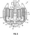
- FIG. 5depicts an end cross-sectional view of the end effector of FIG. 3 , taken along line 5 - 5 of FIG. 3 ;
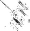
- FIG. 6depicts an exploded perspective view of the end effector of FIG. 3 ;
- FIG. 7depicts a perspective view of the end effector of FIG. 3 , positioned at tissue and having been actuated once in the tissue;
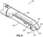
- FIG. 8depicts a perspective view of an alternative version of an end effector with an angled anvil and an angled cartridge
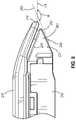
- FIG. 9depicts an enlarged, side view of the end effector of FIG. 8 ;
- FIG. 10depicts an enlarged top view of the end effector of FIG. 8 ;
- FIG. 11depicts a perspective view of an exemplary surgical stapling instrument having an end effector with a curved elastically deformable tip section;
- FIG. 12Adepicts an enlarged side view of a distal portion of the end effector of FIG. 11 ;
- FIG. 12Bdepicts an enlarged side view of a distal portion of an alternate end effector similar to that of FIG. 11 ;
- FIG. 13depicts a partial top view of an alternate anvil of an end effector for use with the surgical instruments described herein;
- FIG. 14Adepicts a cross sectional side view of the anvil of FIG. 13 , taken along line 14 - 14 of FIG. 13 , and showing a tip of the anvil in a first position;
- FIG. 14Bdepicts an enlarged perspective view of the anvil of FIG. 14A , shown with a portion of the anvil in phantom;
- FIG. 15depicts a side view of the anvil of FIG. 13 , showing the tip of the anvil rotated to a second position;
- FIG. 16depicts a cross sectional side view of an alternate anvil of an end effector for use with the surgical instruments described herein, and similar to the anvil of FIG. 14 but having multiple rotatable tip portions;
- FIG. 17depicts a perspective view of an alternate anvil of an end effector for use with the surgical instruments described herein;
- FIG. 18depicts a cross sectional side view of the anvil of FIG. 17 , shown with the elastomeric overmold in phantom, and showing a pivot member pivotable about a fulcrum feature;
- FIG. 19depicts a perspective view of an alternate tip of an anvil of an end effector for use with the surgical instruments described herein, shown with the tip in a first position;
- FIG. 20depicts a perspective view of the tip of FIG. 19 , shown with the tip in a second position;
- FIG. 21depicts a perspective view of a distal portion of another exemplary end effector having an anvil with a selectively rotatable distal tip, showing the distal tip in a first discrete position relative to an anvil body;
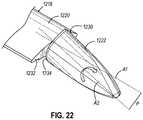
- FIG. 22depicts a perspective view of the body and the distal tip of the anvil of FIG. 21 , showing the distal tip rotating relative to the body between the first discrete position and a second discrete position;
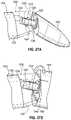
- FIG. 23Adepicts a side elevational view of a distal portion of the end effector of FIG. 21 , showing the distal tip in the first discrete position relative to the body;
- FIG. 23Bdepicts a side elevational view of a distal portion of the end effector of FIG. 21 , showing the distal tip in the second discrete position relative to the body;
- FIG. 24depicts a perspective view of a distal portion of another exemplary anvil having a body, a selectively rotatable distal tip, and a tip locking mechanism, showing the distal tip in a pre-finalized state of assembly and in a second discrete position relative to the body;
- FIG. 25depicts a side sectional view of the distal portion of the anvil of FIG. 24 , showing the distal tip in a finalized state of assembly and in a first discrete position relative to the body;
- FIG. 26depicts a top plan view of a distal portion of another exemplary anvil having a body, a selectively rotatable distal tip, and a tip locking mechanism, showing the distal tip in a first discrete position relative to the body;
- FIG. 27Adepicts a perspective of a distal portion of another exemplary anvil having a body, a rotatable distal tip, and a tip locking mechanism, showing the distal tip partially decoupled from and in a second discrete position relative to the body;
- FIG. 27Bdepicts an enlarged perspective view of the distal portion of the anvil of FIG. 27A , showing the distal tip rotating relative to the body between a first discrete position and the second discrete position;
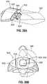
- FIG. 28Adepicts a perspective view of a distal portion of another exemplary anvil having a selectively rotatable distal and a tip locking mechanism, showing the distal tip in a second discrete position and in phantom to reveal features of the tip locking mechanism;
- FIG. 28Bdepicts an end view of the distal portion of the anvil of FIG. 28A , showing the distal tip rotating relative to a connection member between the second discrete position and a first discrete position;
- FIG. 29depicts a perspective of a distal portion of another exemplary anvil having a selectively rotatable distal tip and a tip locking mechanism, showing the distal tip in phantom to reveal internal features;
- FIG. 30depicts a perspective view of an exemplary shaft that permits rotation of the distal tip of the anvil of FIG. 29 ;
- FIG. 31depicts a perspective view of an exemplary clip configured to secure the shaft of FIG. 30 axially relative to the distal tip and a connection member of FIG. 29 ;
- FIG. 32depicts an enlarged perspective view of a distal portion of the shaft of FIG. 30 , showing an exemplary detent feature of the tip locking mechanism of the anvil.
- FIGS. 1-7depict an exemplary surgical stapling and severing instrument ( 10 ) that is sized for insertion, in a nonarticulated state as depicted in FIG. 1 , through a trocar cannula to a surgical site in a patient for performing a surgical procedure.
- a trocarmay be inserted in a patient's abdomen, between two of the patient's ribs, or elsewhere.
- instrument ( 10 )is used without a trocar.
- instrument ( 10 )may be inserted directly through a thoracotomy or other type of incision.
- Instrument ( 10 ) of the present exampleincludes a handle portion ( 20 ) connected to a shaft ( 22 ).
- Shaft ( 22 )distally terminates in an articulation joint ( 11 ), which is further coupled with an end effector ( 12 ).
- end effector12
- proximal and distalare used herein with reference to a clinician gripping handle portion ( 20 ) of instrument ( 10 ).
- end effector ( 12 )is distal with respect to the more proximal handle portion ( 20 ).
- spatial termssuch as “vertical” and “horizontal” are used herein with respect to the drawings. However, surgical instruments are used in many orientations and positions, and these terms are not intended to be limiting and absolute.
- shaft ( 22 )is constructed in accordance with at least some of the teachings of U.S. Pat. No. 9,795,379, entitled “Surgical Instrument with Multi-Diameter Shaft,” issued Oct. 24, 2017, the disclosure of which is incorporated by reference herein.
- Other suitable configurations for shaft ( 22 )will be apparent to those of ordinary skill in the art in view of the teachings herein.
- articulation joint ( 11 )may be remotely articulated, as depicted in phantom in FIG. 1 , by an articulation control ( 13 ), such that end effector ( 12 ) may be deflected from the longitudinal axis (LA) of shaft ( 22 ) at a desired angle (a). End effector ( 12 ) may thereby reach behind an organ or approach tissue from a desired angle or for other reasons.
- articulation joint ( 11 )enables deflection of end effector ( 12 ) along a single plane.
- articulation joint ( 11 )enables deflection of end effector along more than one plane.
- Articulation joint ( 11 ) and articulation control ( 13 )may be configured in accordance with the teachings of any of the numerous references that are cited herein.
- articulation joint ( 11 ) and/or articulation control ( 13 )may have any other suitable configuration.
- articulation control ( 13 )may instead be configured as a knob that rotates about an axis that is perpendicular to the longitudinal axis (LA) of shaft ( 22 ).
- articulation joint ( 11 ) and/or articulation control ( 13 )are/is constructed and operable in accordance with at least some of the teachings of U.S. Pat. No. 9,186,142, entitled “Surgical Instrument End Effector Articulation Drive with Pinion and Opposing Racks,” issued on Nov. 17, 2015, the disclosure of which is incorporated by reference herein.
- Articulation joint ( 11 )may also be constructed and operable in accordance with at least some of the teachings of U.S. Pat. No. 9,795,379, entitled “Surgical Instrument with Multi-Diameter Shaft,” issued Oct. 24, 2017, the disclosure of which is incorporated by reference herein.
- Other suitable forms that articulation joint ( 11 ) and articulation control ( 13 ) may takewill be apparent to those of ordinary skill in the art in view of the teachings herein.
- End effector ( 12 ) of the present exampleincludes a lower jaw ( 16 ) and an upper jaw in the form of a pivotable anvil ( 18 ).
- lower jaw ( 16 )is constructed in accordance with at least some of the teachings of U.S. Pat. No. 9,808,248, entitled “Installation Features for Surgical Instrument End Effector Cartridge,” issued Nov. 7, 2017, the disclosure of which is incorporated by reference herein.
- Anvil ( 18 )may be constructed in accordance with at least some of the teachings of U.S. Pat. No. 9,517,065, entitled “Integrated Tissue Positioning and Jaw Alignment Features for Surgical Stapler,” issued on Dec.
- Handle portion ( 20 )includes a pistol grip ( 24 ) and a closure trigger ( 26 ).
- Closure trigger ( 26 )is pivotable toward pistol grip ( 24 ) to cause clamping, or closing, of the anvil ( 18 ) toward lower jaw ( 16 ) of end effector ( 12 ).
- Such closing of anvil ( 18 )is provided through a closure tube ( 32 ) and a closure ring ( 33 ), which both longitudinally translate relative to handle portion ( 20 ) in response to pivoting of closure trigger ( 26 ) relative to pistol grip ( 24 ).
- Closure tube ( 32 )extends along the length of shaft ( 22 ); and closure ring ( 33 ) is positioned distal to articulation joint ( 11 ). Articulation joint ( 11 ) is operable to communicate/transmit longitudinal movement from closure tube ( 32 ) to closure ring ( 33 ).
- Handle portion ( 20 )also includes a firing trigger ( 28 ).
- An elongate member(not shown) longitudinally extends through shaft ( 22 ) and communicates a longitudinal firing motion from handle portion ( 20 ) to a firing beam ( 14 ) in response to actuation of firing trigger ( 28 ).
- This distal translation of firing beam ( 14 )causes the stapling and severing of clamped tissue in end effector ( 12 ), as will be described in greater detail below.
- triggers ( 26 , 28 )may be released to release the tissue from end effector ( 12 ).
- FIGS. 3-6depict end effector ( 12 ) employing an E-beam form of firing beam ( 14 ) to perform a number of functions.
- Firing beam ( 14 )may take any other suitable form, including but not limited to non-E-beam forms.
- firing beam ( 14 )includes a transversely oriented upper pin ( 38 ), a firing beam cap ( 44 ), a transversely oriented middle pin ( 46 ), and a distally presented cutting edge ( 48 ).
- Upper pin ( 38 )is positioned and translatable within a longitudinal anvil slot ( 42 ) of anvil ( 18 ).
- Firing beam cap ( 44 )slidably engages a lower surface of lower jaw ( 16 ) by having firing beam ( 14 ) extend through lower jaw slot ( 45 ) (shown in FIG. 4B ) that is formed through lower jaw ( 16 ).
- Middle pin ( 46 )slidingly engages a top surface of lower jaw ( 16 ), cooperating with firing beam cap ( 44 ). Thereby, firing beam ( 14 ) affirmatively spaces end effector ( 12 ) during firing.
- firing beam ( 14 )may lack upper pin ( 38 ), middle pin ( 46 ) and/or firing beam cap ( 44 ). Some such versions of instrument ( 10 ) may simply rely on closure ring ( 33 ) or some other feature to pivot anvil ( 18 ) to a closed position and hold anvil ( 18 ) in the closed position while firing beam ( 14 ) advances to the distal position.
- firing beam ( 14 ) and/or associated lockout featuresmay be constructed and operable in accordance with at least some of the teachings of U.S. Pat. No. 9,717,497, entitled “Lockout Feature for Movable Cutting Member of Surgical Instrument,” issued Aug. 1, 2017, the disclosure of which is incorporated by reference herein.
- Other suitable forms that firing beam ( 14 ) may takewill be apparent to those of ordinary skill in the art in view of the teachings herein.
- FIG. 3shows firing beam ( 14 ) of the present example proximally positioned and anvil ( 18 ) pivoted to an open position, allowing an unspent staple cartridge ( 37 ) to be removably installed into a channel of lower jaw ( 16 ).
- staple cartridge ( 37 ) of this exampleincludes a cartridge body ( 70 ), which presents an upper deck ( 72 ) and is coupled with a lower cartridge tray ( 74 ).
- a vertical slot ( 49 )is formed through part of staple cartridge ( 37 ).
- FIG. 3shows firing beam ( 14 ) of the present example proximally positioned and anvil ( 18 ) pivoted to an open position, allowing an unspent staple cartridge ( 37 ) to be removably installed into a channel of lower jaw ( 16 ).
- staple cartridge ( 37 ) of this exampleincludes a cartridge body ( 70 ), which presents an upper deck ( 72 ) and is coupled with a lower cartridge tray ( 74 ).
- a vertical slot ( 49 )is formed through part of staple cartridge
- three rows of staple apertures ( 51 )are formed through upper deck ( 72 ) on one side of vertical slot ( 49 ), with another set of three rows of staple apertures ( 51 ) being formed through upper deck ( 72 ) on the other side of vertical slot ( 49 ).
- any other suitable number of staple rowse.g., two rows, four rows, any other number
- a wedge sled ( 41 ) and a plurality of staple drivers ( 43 )are captured between cartridge body ( 70 ) and tray ( 74 ), with wedge sled ( 41 ) being located proximal to staple drivers ( 43 ).
- Wedge sled ( 41 )is movable longitudinally within staple cartridge ( 37 ); while staple drivers ( 43 ) are movable vertically within staple cartridge ( 37 ). Staples ( 47 ) are also positioned within cartridge body ( 70 ), above corresponding staple drivers ( 43 ). In particular, each staple ( 47 ) is driven vertically within cartridge body ( 70 ) by a staple driver ( 43 ) to drive staple ( 47 ) out through an associated staple aperture ( 51 ). As best seen in FIGS. 4A-4B and 6 , wedge sled ( 41 ) presents inclined cam surfaces that urge staple drivers ( 43 ) upwardly as wedge sled ( 41 ) is driven distally through staple cartridge ( 37 ).
- staple cartridge ( 37 )is constructed and operable in accordance with at least some of the teachings of U.S. Pat. No. 9,517,065, entitled “Integrated Tissue Positioning and Jaw Alignment Features for Surgical Stapler,” issued Dec. 13, 2016, the disclosure of which is incorporated by reference herein.
- staple cartridge ( 37 )may be constructed and operable in accordance with at least some of the teachings of U.S. Pat. No. 9,808,248, entitled “Installation Features for Surgical Instrument End Effector Cartridge,” issued Nov. 7, 2017, the disclosure of which is incorporated by reference herein.
- Other suitable forms that staple cartridge ( 37 ) may takewill be apparent to those of ordinary skill in the art in view of the teachings herein.
- firing beam ( 14 )is then advanced in engagement with anvil ( 18 ) by having upper pin ( 38 ) enter longitudinal anvil slot ( 42 ).
- a pusher block ( 80 )(shown in FIG. 5 ) is located at the distal end of firing beam ( 14 ), and is configured to engage wedge sled ( 41 ) such that wedge sled ( 41 ) is pushed distally by pusher block ( 80 ) as firing beam ( 14 ) is advanced distally through staple cartridge ( 37 ) when firing trigger ( 28 ) is actuated.
- middle pin ( 46 ) and pusher block ( 80 )together actuate staple cartridge ( 37 ) by entering into vertical slot ( 49 ) within staple cartridge ( 37 ), driving wedge sled ( 41 ) into upward camming contact with staple drivers ( 43 ) that in turn drive staples ( 47 ) out through staple apertures ( 51 ) and into forming contact with staple forming pockets ( 53 ) (shown in FIG. 3 ) on the inner surface of anvil ( 18 ).
- FIG. 4A-4Bmiddle pin ( 46 ) and pusher block ( 80 ) together actuate staple cartridge ( 37 ) by entering into vertical slot ( 49 ) within staple cartridge ( 37 ), driving wedge sled ( 41 ) into upward camming contact with staple drivers ( 43 ) that in turn drive staples ( 47 ) out through staple apertures ( 51 ) and into forming contact with staple forming pockets ( 53 ) (shown in FIG. 3 ) on the inner surface of anvil ( 18 ).
- FIG. 4Bdepicts firing beam ( 14 ) fully distally translated after completing severing and stapling of tissue. It should be understood that staple forming pockets ( 53 ) are intentionally omitted from the view in FIGS. 4A-4B ; but staple forming pockets ( 53 ) are shown in FIG. 3 . It should also be understood that anvil ( 18 ) is intentionally omitted from the view in FIG. 5 .
- FIG. 7shows end effector ( 12 ) having been actuated through a single stroke through tissue ( 90 ).
- cutting edge ( 48 )(obscured in FIG. 7 ) has cut through tissue ( 90 ), while staple drivers ( 43 ) have driven three alternating rows of staples ( 47 ) through the tissue ( 90 ) on each side of the cut line produced by cutting edge ( 48 ).
- Staples ( 47 )are all oriented substantially parallel to the cut line in this example, though it should be understood that staples ( 47 ) may be positioned at any suitable orientations.
- end effector ( 12 )is withdrawn from the trocar after the first stroke is complete, spent staple cartridge ( 37 ) is replaced with a new staple cartridge, and end effector ( 12 ) is then again inserted through the trocar to reach the stapling site for further cutting and stapling. This process may be repeated until the desired amount of cuts and staples ( 47 ) have been provided.
- Anvil ( 18 )may need to be closed to facilitate insertion and withdrawal through the trocar; and anvil ( 18 ) may need to be opened to facilitate replacement of staple cartridge ( 37 ).
- cutting edge ( 48 )may sever tissue substantially contemporaneously with staples ( 47 ) being driven through tissue during each actuation stroke.
- cutting edge ( 48 )just slightly lags behind driving of staples ( 47 ), such that a staple ( 47 ) is driven through the tissue just before cutting edge ( 48 ) passes through the same region of tissue, though it should be understood that this order may be reversed or that cutting edge ( 48 ) may be directly synchronized with adjacent staples. While FIG.
- end effector ( 12 )being actuated in two layers ( 92 , 94 ) of tissue ( 90 )
- end effector ( 12 )may be actuated through a single layer of tissue ( 90 ) or more than two layers ( 92 , 94 ) of tissue.
- the formation and positioning of staples ( 47 ) adjacent to the cut line produced by cutting edge ( 48 )may substantially seal the tissue at the cut line, thereby reducing or preventing bleeding and/or leaking of other bodily fluids at the cut line.
- FIG. 7shows end effector ( 12 ) being actuated in two substantially flat, apposed planar layers ( 92 , 94 ) of tissue, it should be understood that end effector ( 12 ) may also be actuated across a tubular structure such as a blood vessel, a section of the gastrointestinal tract, etc. FIG. 7 should therefore not be viewed as demonstrating any limitation on the contemplated uses for end effector ( 12 ).
- instrument ( 10 )may be used will be apparent to those of ordinary skill in the art in view of the teachings herein.
- instrument ( 10 )provides motorized control of firing beam ( 14 ).
- Exemplary components that may be used to provide motorized control of firing beam ( 14 )are shown and described in U.S. Pat. No. 9,622,746, entitled “Distal Tip Features for End Effector of Surgical Instrument,” issued Apr. 18, 2017, the disclosure of which is incorporated by reference herein.
- at least part of the motorized controlmay be configured in accordance with at least some of the teachings of U.S. Pat. No. 8,210,411, entitled “Motor-Driven Surgical Instrument,” issued Jul. 3, 2012, the disclosure of which is incorporated by reference herein.
- firing beam ( 14 )may be configured in accordance with at least some of the teachings of U.S. Pat. No. 8,453,914, the disclosure of which is incorporated by reference herein; and/or in accordance with at least some of the teachings of U.S. Pat. No. 8,453,914, the disclosure of which is also incorporated by reference herein.
- Other suitable components, features, and configurations for providing motorization of firing beam ( 14 )will be apparent to those of ordinary skill in the art in view of the teachings herein. It should also be understood that some other versions may provide manual driving of firing beam ( 14 ), such that a motor may be omitted.
- firing beam ( 14 )may be actuated in accordance with at least some of the teachings of any other patent/publication reference cited herein.
- Instrument ( 10 )may also include a lockout switch and lockout indicator as shown and described in U.S. Pat. No. 9,622,746, entitled “Distal Tip Features for End Effector of Surgical Instrument,” issued Apr. 18, 2017, the disclosure of which is incorporated by reference herein. Additionally, a lockout switch and/or lockout indication and associated components/functionality may be configured in accordance with at least some of the teachings of U.S. Pat. No. 7,644,848, entitled “Electronic Lockouts and Surgical Instrument Including Same,” issued Jan. 12, 2010, the disclosure of which is incorporated by reference herein.
- Instrument ( 10 )also include a manual return switch ( 116 ) configured to act as a “bailout” feature, enabling the operator to quickly begin retracting firing beam ( 14 ) proximally during a firing stroke.
- manual return switch ( 116 )may be manually actuated when firing beam ( 14 ) has only been partially advanced distally.
- Manual return switch ( 116 )may provide further functionality in accordance with at least some of the teachings of U.S. Pat. No. 9,622,746, entitled “Distal Tip Features for End Effector of Surgical Instrument,” issued Apr. 18, 2017, the disclosure of which is incorporated by reference herein.
- anvil ( 18 )pivots about an axis that is defined by a pin (or similar feature) that slides along an elongate slot or channel as anvil ( 18 ) moves toward lower jaw ( 16 ). In such versions, the pivot axis translates along the path defined by the slot or channel while anvil ( 18 ) simultaneously pivots about that axis.
- pivot axismay slide along the slot/channel first, with anvil ( 18 ) then pivoting about the pivot axis after the pivot axis has slid a certain distance along the slot/channel.
- sliding/translating pivotal movementis encompassed within terms such as “pivot,” “pivots,” “pivotal,” “pivotable,” “pivoting,” and the like.
- some versionsmay provide pivotal movement of anvil ( 18 ) about an axis that remains fixed and does not translate within a slot or channel, etc.
- instrument ( 10 )may be configured and operable in accordance with any of the teachings of U.S. Pat. Nos. 4,805,823; 5,415,334; 5,465,895; 5,597,107; 5,632,432; 5,673,840; 5,704,534; 5,814,055; 6,978,921; 7,000,818; 7,143,923; 7,303,108; 7,367,485; 7,380,695; 7,380,696; 7,404,508; 7,434,715; 7,721,930; 8,408,439; and/or 8,453,914.
- the disclosures of each of those patents and publicationsare incorporated by reference herein.
- instrument ( 10 )Additional exemplary modifications that may be provided for instrument ( 10 ) will be described in greater detail below.
- Various suitable ways in which the below teachings may be incorporated into instrument ( 10 )will be apparent to those of ordinary skill in the art.
- various suitable ways in which the below teachings may be combined with various teachings of the patents/publications cited hereinwill be apparent to those of ordinary skill in the art.
- the below teachingsare not limited to instrument ( 10 ) or devices taught in the patents cited herein.
- the below teachingsmay be readily applied to various other kinds of instruments, including instruments that would not be classified as surgical staplers.
- Various other suitable devices and settings in which the below teachings may be appliedwill be apparent to those of ordinary skill in the art in view of the teachings herein.
- end effector ( 12 )it may be desirable to provide the user with better visualization of end effector ( 12 ).
- the usermay rotate shaft ( 22 ) of instrument ( 10 ) during the procedure.
- end effector ( 12 )also rotates.
- end effector ( 12 )could be rotated such that when the user views end effector ( 12 ), anvil ( 18 ) is visible by the user. It may be desirable to provide visibility of the surgical site for the user beyond what is possible in instrument ( 10 ) of FIG. 1 . For instance, in the case of some surgical procedures where fluid carrying vessels are transected and stapled, it may be desirable to have visual confirmation that anvil ( 18 ) and lower jaw ( 16 ) completely cover the vessel to be cut, such that the vessel may be fully cut and stapled in one single actuation. In other words, the user may wish to avoid cutting and stapling only a portion of a vessel.
- Some means of visual monitoring and/or feedbackmay be desirable so that the user will know that end effector ( 12 ) has been positioned properly within the surgical site for anvil ( 18 ) and lower jaw ( 16 ) to fully clamp the vessel.
- One potential way of monitoring the surgical sitemay include improving visualization of the area adjacent to the distal tip of lower jaw ( 16 ) and anvil ( 18 ).
- end effector ( 12 )may be desirable, but also it may be desirable to construct end effector ( 12 ) such that the distal end of anvil ( 18 ) is configured to urge tissue (e.g., a large vessel) proximally into the space between anvil ( 18 ) and lower jaw ( 16 ) as anvil ( 18 ) closes toward lower jaw ( 16 ).
- tissuee.g., a large vessel
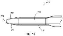
- FIG. 8depicts an exemplary end effector ( 212 ) comprising an anvil ( 218 ) and a lower jaw ( 216 ). It will be appreciated that end effector ( 212 ) may be used in place of end effector ( 12 ) of instrument ( 10 ). End effector ( 212 ) may be integrally formed with instrument ( 10 ) or in the alternative may be interchangeable with end effector ( 12 ) of instrument ( 10 ).
- Anvil ( 218 )is operable to pivot relative to lower jaw ( 216 ).
- Anvil ( 218 ) and lower jaw ( 216 )may clamp tissue ( 90 ) similarly to clamping performed by anvil ( 18 ) and lower jaw ( 16 ) shown in FIG. 1 .
- End effector ( 212 )further comprises a cartridge ( 237 ) operable to be placed in lower jaw ( 216 ) similarly to cartridge ( 37 ) shown in FIG. 3 .
- Anvil ( 218 ) as can be seen in FIGS. 8-10has an elongated shape where the distal portion of anvil ( 218 ) angles toward cartridge ( 237 ).
- the distal portion of anvil ( 218 )angles toward cartridge ( 237 ) such that the distal most tip ( 219 ) of anvil ( 218 ) extends distally longitudinally further than cartridge ( 237 ).
- distal tip ( 219 )may extend to a distance longitudinally equal to cartridge ( 237 ) or proximal relative to the distal most point on cartridge ( 237 ).
- anvil ( 218 )angles toward cartridge ( 237 ) through a gentle slope. As seen best in FIG.
- anvil ( 218 )includes sides ( 241 ) that taper as they approach the distal most tip ( 219 ) of anvil ( 218 ).
- anvil ( 218 )is shaped in FIG. 8 similarly to an inverted ski tip.
- the angled shape of anvil ( 218 )may provide easier insertion of end effector ( 212 ) into a surgical site.
- the gentle slope or inverted ski tip shape of anvil ( 218 )may provide an atraumatic tissue deflection surface as anvil ( 218 ) contacts or moves through tissue.
- Such atraumatic tissue deflectionmay include urging tissue (e.g., a large vessel) proximally into the space between anvil ( 218 ) and lower jaw ( 216 ) as anvil ( 218 ) closes toward lower jaw ( 216 ).
- tissuee.g., a large vessel
- the angled shape of anvil ( 218 )may also provide better maneuverability of end effector ( 212 ) and better visibility of the distal end of end effector ( 212 ) in relation to anatomical structures at the surgical site.
- Other suitable variations of anvil ( 218 )will be apparent to one of ordinary skill in the art in view of the teachings herein.
- Cartridge ( 237 )is operable to hold staples similar to staples ( 47 ) shown in FIG. 4A for driving into tissue.
- the distal end of cartridge ( 237 )has a triangular profile.
- the distal end of cartridge ( 237 )comprises an upper tapered surface ( 239 ) and a lower tapered surface ( 238 ).
- the distal end of cartridge ( 237 )comprises a tapered side surface ( 243 ) on each side.
- each tapered side surface ( 243 ) of cartridge ( 237 )generally aligns with the taper presented by sides ( 241 ) of anvil ( 218 ).
- side surfaces ( 243 ) of cartridge ( 237 )do not extend outwardly from longitudinal axis (LA) of end effector ( 212 ) past sides ( 241 ) of anvil ( 218 ).
- Upper tapered surface ( 239 ) and lower tapered surface ( 238 )lead to the distal most end of cartridge ( 237 ).
- Lower tapered surface ( 238 )defines a sight line ( 240 ) such that once end effector ( 212 ) is inserted into a surgical site, the user can see along sight line ( 240 ).
- Sight line ( 240 )extends along the edge of lower tapered surface ( 238 ).
- planar shape of lower tapered surface ( 238 )may be operable to allow the user to visualize and/or nearly visualize the distal tip ( 219 ) of anvil ( 218 ).
- sight line ( 240 )intersects longitudinal axis (LA), which extends longitudinally through end effector ( 212 ), to form a viewing angle ( ⁇ ).
- Viewing angle ( ⁇ )may establish the relative visibility that a user has regarding distal tip ( 219 ).
- the usercan see in front of distal tip ( 219 ) along any line of sight that passes through the intersection of sight line ( 240 ) and longitudinal axis (LA) within viewing angle ( ⁇ ).
- viewing angle ( ⁇ )defines an angle greater than 90 degrees.
- viewing angle ( ⁇ )defines an angle greater than 135 degrees.
- viewing angle ( ⁇ )Other suitable angles for viewing angle ( ⁇ ) will be apparent to one of ordinary skill in the art in view of the teachings herein.
- the usergenerally looks along sight line ( 240 ) or along some other line of sight within viewing angle ( ⁇ ), thus, the user has visibility along sight line as well as any area within viewing angle ( ⁇ ).
- the underside of distal tip ( 219 )is further slightly rounded to aid in the visibility of the intersection of longitudinal axis (LA) and sight line ( 240 ).
- tissue ( 90 )When tissue ( 90 ) is clamped between a closed cartridge ( 237 ) and anvil ( 218 ), the user can look along sight line ( 240 ) or elsewhere within viewing angle ( ⁇ ) to see, for instance, precisely where anvil ( 218 ) has clamped tissue ( 90 ). Furthermore, the user would be able to determine whether the tissue is completely clamped between anvil ( 218 ) and cartridge ( 237 ) such that tissue does not spill over the end of end effector ( 212 ). The user may be able to also visualize the quality of the clamp between anvil ( 218 ) and cartridge ( 237 ) against tissue ( 90 ). It will be appreciated that in some instances, end effector ( 212 ) may be rotated before, during, or after clamping tissue ( 90 ).
- the tapered shape of anvil ( 218 )may also provide more accessible viewing of distal tip ( 219 ) or substantially adjacent distal tip ( 219 ).
- the taper of anvil ( 218 ) along with lower tapered surface ( 238 ) of cartridge ( 237 )may further promote easy insertion of end effector ( 212 ) into tissue in an atraumatic manner.
- itmay be easier to fit end effector ( 212 ) through a trocar or other devices operable to introduce end effector ( 212 ) into a surgical site due to the tapered end of end effector ( 212 ).
- lower tapered surface ( 238 ) and the tapered shape of anvil ( 218 )may provide a lead-in, guiding the rest of end effector ( 212 ) into the trocar.
- visibility and maneuverabilitycan be enhanced by the tapered design for both sides ( 241 ) of anvil ( 218 ) and each side ( 243 ) of cartridge ( 237 ).
- end effector ( 212 ) and versions of instrument ( 10 ) incorporating end effector ( 212 )may be configured and operable in accordance with at least some of the teachings of U.S. Pat. No. 9,186,142, entitled “Surgical Instrument End Effector Articulation Drive with Pinion and Opposing Racks,” issued Nov. 17, 2015, the disclosure of which is incorporated by reference herein; U.S. Pat. No. 9,717,497, entitled “Lockout Feature for Movable Cutting Member of Surgical Instrument,” issued Aug. 1, 2017, the disclosure of which is incorporated by reference herein; U.S. Pat. No. 9,517,065, entitled “Integrated Tissue Positioning and Jaw Alignment Features for Surgical Stapler,” issued Dec.
- instrument ( 10 )may be placed at the surgical site, actuated to cut and staple, then removed from the surgical site for installing a new cartridge ( 37 ), and then be placed back at the surgical site again for the next cut and staple along the same path in which the previous cutting and stapling cycle occurred. This process is repeated until the cut and staple procedure is complete. As can be seen in FIGS. 4A-4B and FIG.
- the distal end configuration of end effector ( 12 )provides a gap between the distal end of anvil ( 18 ) and the distal end of cartridge ( 37 ). This gap may facilitate marching by providing an atraumatic space for tissue to enter the distal end of end effector ( 12 ) at the beginning of each marching step.
- the distal end configuration of end effector ( 212 )is different from the distal end configuration of end effector ( 12 ); with the different configuration of end effector ( 212 ) providing different potential advantages.
- the distal end configuration of end effector ( 212 )may provide improved maneuverability and improved visibility of the relationship between the distal end of end effector ( 212 ) and adjacent anatomical structures.
- the distal end configuration of end effector ( 212 )may provide tissue-gathering effects by urging tissue proximally into the space between anvil ( 218 ) and lower jaw ( 216 ) as anvil ( 218 ) is closed toward lower jaw ( 216 ).
- end effector ( 212 )may not lend itself well to marching operations, as distal tip ( 219 ) may impart trauma to tissue that is not gathered into the space between anvil ( 218 ) and lower jaw ( 216 ) as anvil ( 218 ) is closed toward lower jaw ( 216 ).
- end effector ( 212 )may be best suited for cutting and stapling operations (e.g., vessel transection) where all of the tissue that is to be cut and stapled is gathered proximal to distal tip ( 219 ).
- an anvilhas a distal tip that is resiliently biased to assume a bent or angled configuration like distal tip ( 219 ); yet the resiliently biased distal tip is deflectable away from the lower jaw in response to a sufficient load on the distal tip.
- an anvil with an elastically deformable angled distal tip portioncan provide an additional level of maneuverability benefits in terms of navigating through tissue to a surgical site.
- the deformable distal tip portionmay deflect or deform to promote smooth and atraumatic movement of the end effector through tissue, particularly during marching operations.
- an anvil having a bias to an angled position when not in a loaded state or contacted by surrounding tissueenhanced visualization during tissue capture and cutting can be achieved compared to using end effectors with a straight or non-angled anvil.
- an anvil with a distal tip that is biased to an angled positionmay provide some degree of tissue gathering effects up until reaching a load point that would be associated with marching rather than being associated with simply gathering a relatively small tissue structure between the anvil and lower jaw.
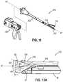
- FIG. 11shows another exemplary instrument ( 310 ) configured as a surgical stapler.
- Instrument ( 310 )comprises a handle portion ( 320 ) and a shaft ( 322 ).
- Instrument ( 310 )has a modular configuration such that shaft ( 322 ) is selectively removable from, and attachable to, handle portion ( 320 ).
- Instrument ( 310 )is configured similarly to instrument ( 10 ) such that the operability and use of instrument ( 310 ) is the same as described above for instrument ( 10 ) with the added feature of instrument ( 310 ) being a modular configuration. With its modular configuration, instrument ( 310 ) provides a way to change the end effector.
- instrument ( 310 )may be configured in accordance with at least some of the teachings of U.S. Pat. No. 10,182,813, entitled “Surgical Stapling Instrument with Shaft Release, Powered Firing, and Powered Articulation,” issued Jan. 22, 2019, the disclosure of which is incorporated by reference herein.
- Other suitable components, features, and configurations for providing instrument ( 310 ) with a modular configurationwill be apparent to those of ordinary skill in the art in view of the teachings herein.
- instrument ( 10 )may be modified to incorporate a modular configuration as shown and described with respect to instrument ( 310 ) or other instruments incorporated by reference herein.
- instrument ( 310 )comprises an end effector ( 312 ) having an anvil ( 318 ) that has an angled distal tip ( 319 ). Furthermore, distal tip ( 319 ) of anvil ( 318 ) is elastically deformable. In this manner, and as shown best in FIGS. 12A and 12B , angled distal tip ( 319 ) is operable to elastically deform from a first angled position to a second position.
- the second position for angled distal tip ( 319 )may be substantially straight in some versions, but may be angled to a degree (e.g., slightly above or slightly below the longitudinal axis (A 1 )) in other versions.
- the second position for angled distal tip ( 319 )may be defined by the characteristics (e.g., thickness, density, etc.) of the tissue that is being captured between anvil ( 318 ) and lower jaw ( 16 ).
- end effector ( 312 )is provided on shaft ( 322 ) that is detachable from handle portion ( 320 ).
- shaft ( 322 )may be detachable from handle portion ( 320 ) in accordance with at least some of the teachings of U.S. Pat. No. 9,913,642, entitled “Surgical Instrument Comprising a Sensor System,” issued Mar. 13, 2018, the disclosure of which is incorporated by reference herein. In some other versions, shaft ( 322 ) is not detachable from handle portion ( 320 ).
- end effector ( 312 )may be used in place of end effector ( 12 ) shown in FIG. 1 .
- end effector ( 312 )may be integrally formed with shaft ( 22 ) or alternatively may be separately formed and then combined.
- end effector ( 312 )may be provided for use in robotic systems. In such robotic systems, modular shaft ( 322 ) having end effector ( 312 ) may be attachable to a portion of the robotic system for use such that handle portion ( 320 ) is replaced by components of the robotic system.
- end effector ( 312 )may be adapted for use with a robotic system in a manner where end effector ( 312 ) connects with the robotic system without necessarily connecting the entire modular shaft ( 322 ).
- end effector ( 312 )may be adapted for use with a robotic system in a manner where end effector ( 312 ) connects with the robotic system without necessarily connecting the entire modular shaft ( 322 ).
- FIG. 12Ashows an enlarged side view of the distal end of end effector ( 312 ).
- End effector ( 312 )comprises anvil ( 318 ) and lower jaw ( 16 ) that accepts cartridge ( 37 ) as described above with respect to instrument ( 10 ).
- Anvil ( 318 )pivotably rotates toward lower jaw ( 16 ) in the same manner as anvil ( 18 ) as described above with respect to instrument ( 10 ).
- end effector ( 312 )is similar to end effector ( 12 ), however, anvil ( 318 ) comprises angled distal tip ( 319 ) that is elastically deformable. As shown in FIG. 12A , tip ( 319 ) is imparted with a bias to an angled position that is shown in FIG.
- Tip ( 319 )assumes this angled position when end effector ( 312 ) is not clamping tissue and is open, as shown in FIG. 11 ; or closed without clamping tissue, as shown in phantom in FIG. 12A .
- end effector ( 312 )can be considered not loaded or in a non-loaded state or position.
- end effector ( 312 )can be considered loaded or in a loaded state or position.
- an underside surface ( 324 ) of tip ( 319 )defines a plane that intersects a longitudinal axis (A 1 ) defined by shaft ( 322 ) to form an angle ( ⁇ 1 ).
- underside surface ( 324 ) of tip ( 319 )contacts tissue ( 90 ).
- underside surface ( 324 ) of tip ( 319 )defines a plane that intersects longitudinal axis (A 1 ) to form an angle ( ⁇ 2 ).
- angles ( ⁇ 1 , ⁇ 2 )are relative to longitudinal axis (A 1 ), and the sum of angles ( ⁇ 1 , ⁇ 2 ) represent the range of motion distal tip ( 319 ) undergoes.
- angle ( ⁇ 1 )is between about 20 and about 70 degrees, or more particularly between about 30 degrees and about 50 degrees, in a downward direction from longitudinal axis (A 1 ) toward cartridge ( 37 ).
- angle ( ⁇ 2 )is between about 0 and about 90 degrees in an upward direction from longitudinal axis (A 1 ) away from cartridge ( 37 ).
- the range of motion undergone by tip ( 319 )is between about 20 degrees and about 110 degrees.
- the angles described for angles ( ⁇ 1 , ⁇ 2 )are exemplary only and not limiting. Other suitable angles will be apparent to those of ordinary skill in the art in view of the teachings herein.
- longitudinal axis (A 1 )represents a zero-degree reference and angles relative thereto may be positive or negative.
- the anglemay be characterized as a negative angle.
- an angleis in an upward direction from longitudinal axis (A 1 ) away from cartridge ( 37 )
- the anglemay be characterized as a positive angle.
- the range of motion of distal tip ( 319 ) due to deformationcan be understood as the sum of the absolute value of the angle when distal tip ( 319 ) is in the position contacting cartridge ( 37 ), and the angle when distal tip ( 319 ) is in the deformed state when clamping tissue.
- FIG. 12Bshows another side view of an alternate end effector ( 412 ) similar to end effector ( 312 ) of FIG. 12A .
- end effector ( 312 )when anvil ( 318 ) is in its angled and non-deformed state (as seen in phantom in the view of FIG. 12A ), anvil ( 318 ) extends to a point even with or proximal to the distal most end of cartridge ( 37 ).
- anvil ( 318 )is deformed such that it is deflected upwardly, the end of distal tip ( 319 ) extends to a point just distal to the distal most end of cartridge ( 37 ).
- end effector ( 412 )as shown in FIG.
- anvil ( 318 )when anvil ( 318 ) is in its angled and non-deformed state (as seen in phantom in the view of FIG. 12B ), anvil ( 318 ) extends to a point even with or proximal to the distal most end of cartridge ( 37 ).
- anvil ( 318 )is deformed such that it is deflected upwardly, the end of a distal tip ( 319 ) of anvil ( 318 ) extends to a point even with or proximal to the distal most end of cartridge ( 37 ).
- anvil ( 318 ) of end effector ( 412 )remains even with or proximal to the distal most end of cartridge ( 37 ) when anvil ( 318 ) is in its angled state or deformed state such that anvil ( 318 ) does not extend past the distal most end of cartridge ( 37 ) whether anvil ( 318 ) is in its angled and non-deformed state or in its deformed state. In some instances, this can be achieved by modifying anvil ( 318 ) such that distal tip ( 319 ) of anvil is shortened in length. In other instances, instruments ( 10 , 310 ) may be modified to provide for a slight proximal retraction of anvil ( 318 ) when clamping. In view of the teachings herein, other ways to modify end effector ( 412 ) as it relates to control of anvil ( 318 ) position, will be apparent to those of ordinary skill in the art.
- tissuee.g., a large vessel
- angled and “bent” as used herein in connection with the various exemplary anvil tips disclosedencompass tip configurations in which the tip defines a flat planar exterior surface that extends angularly in a distal direction from the distal end of the anvil body; and also tip configurations in which the tip defines a curved exterior surface that extends arcuately in a distal direction from the distal end of the anvil body (e.g., where the tip is said to be in a “curved” configuration).
- a distal end of the anvil tipis vertically offset from a longitudinal axis of the anvil body along an axis that extends transversely to the longitudinal axis and through the corresponding staple cartridge, such that the tip as a whole is “angled” or “bent” relative to the anvil body.
- FIGS. 13-16depict exemplary anvils ( 518 , 118 ) usable with the end effectors described herein and others.
- anvils ( 518 , 118 )can be interchanged or used in place of anvils ( 18 , 218 , 318 ) of respective end effectors ( 12 , 212 , 312 , 412 ) described above.
- end effectors ( 12 , 212 , 312 , 412 ) incorporating either of anvils ( 518 , 118 )may be used with instruments ( 10 , 310 ) and the other surgical instruments described herein.
- end effectors ( 12 , 212 , 312 , 412 ) incorporating either of anvils ( 518 , 118 )may be integrally formed with instruments ( 10 , 310 ) and the other surgical instruments described herein, or in the alternative may be interchangeable end effectors of instruments ( 10 , 310 ) and the other surgical instruments described herein.
- anvils ( 518 , 118 )are operable to pivot relative to lower jaws ( 16 , 216 ).
- Anvils ( 518 , 118 ) and lower jaws ( 16 , 216 )may clamp tissue ( 90 ) similarly to clamping performed by anvil ( 18 ) and lower jaw ( 16 ) shown in FIG. 7 .
- Anvils ( 518 , 118 ) and lower jaws ( 16 , 216 )may further cut and staple clamped tissue ( 90 ) similarly to the cutting and stapling performed by anvil ( 18 ) and lower jaw ( 16 ) shown in FIG. 7 .
- end effectors ( 12 , 212 , 312 , 412 ) incorporating either of anvils ( 518 , 118 )further comprises a cartridge ( 37 , 237 ) containing staples where cartridge ( 37 , 237 ) is operable to be placed in lower jaw ( 16 , 216 ).
- Anvil ( 518 )comprises a body ( 520 ) and a tip ( 519 ) extending distally from body ( 520 ). Proximal to tip ( 519 ), anvil ( 518 ) comprises an extension ( 502 ) on body ( 520 ). Anvil ( 518 ) further comprises a pair of spaced apart detents ( 504 ). A portion of detents ( 504 ) located on extension ( 502 ) are configured as raised portions or protrusions ( 510 ) as shown in the illustrated version. The other portion of detents ( 504 ) are located on tip ( 519 ) and are configured as recesses ( 523 ) as will be discussed further below.
- Anvil ( 518 )also comprises a bore ( 506 ) that extends through the sides of body ( 520 ) of anvil ( 518 ) and bore ( 506 ) is configured to receive a pin ( 508 ).
- pin ( 508 )defines an axis of rotation about which tip ( 519 ) is rotatable.
- Tip ( 519 )comprises a bore ( 521 ) that extends through the sides of tip ( 519 ) and bore ( 521 ) is configured to also receive pin ( 508 ). In this manner, tip ( 519 ) is operable to rotate about pin ( 508 ) and thus rotate relative to a longitudinal axis (A 2 ) of anvil ( 518 ). Bores ( 506 , 521 ) have a circular shape, but in other examples have an elongated shape. In some instances an elongated shape for bores ( 506 , 521 ) provides for or contributes to tip ( 519 ) assuming different discrete positions as discussed further below.
- tip ( 519 )comprises a pair of recesses ( 523 ) that are configured to be selectively engageable with raised portions or protrusions ( 510 ) of detents ( 504 ).
- tip ( 519 )comprises a pair of slots ( 525 ) that extend longitudinally and define a resilient portion ( 527 ).
- resilient portion ( 527 )comprises recesses ( 523 ) along an underside of resilient portion ( 527 ).
- anvil ( 518 )is configured with tip ( 519 ) that can be moved into discrete positions.
- Detents ( 504 )provide for selective engagement between raised portions ( 510 ) of detents ( 504 ) and recesses ( 523 ) of detents ( 504 ), which allow for tip ( 519 ) to move to different discrete positions.
- FIG. 14Aillustrates tip ( 519 ) is a first position that has tip ( 519 ) in a straight orientation such that a longitudinal axis of tip ( 519 ) is generally parallel with or coincides with longitudinal axis (A 2 ) of anvil ( 518 ).
- tip ( 519 ) in a second positionthat has tip ( 519 ) in An angled orientation such that the longitudinal axis of tip ( 519 ) forms an angle with longitudinal axis (A 2 ) of anvil ( 518 ) that is less than about 180 degrees.
- slots ( 525 )define resilient portion ( 527 ), such that resilient portion ( 527 ) acts as a spring to thereby allow tip ( 519 ) to change positions by recesses ( 523 ) engaging raised portions ( 510 ) in different manners. For instance, when in the straight orientation as shown in FIG. 14A , the proximal most recess ( 523 ) engages with the proximal most raised portion ( 510 ). Similarly, in this straight orientation the distal most recess ( 523 ) engages with the distal most raised portion ( 510 ). When in the angled orientation as shown in FIG.
- the proximal most recess ( 523 )engages with the distal most raised portion ( 510 ). Furthermore, in this angled orientation the distal most recess ( 523 ) is not engaged with either raised portion ( 510 ).
- anvil ( 518 )comprises a stop feature ( 500 ) that is configured to contact a proximal end of tip ( 519 ) and prevent tip ( 519 ) from moving to an even further angled position.
- tip ( 519 )is configured to adopt discrete positions where tip ( 519 ) remains in one of the discrete positions until acted upon by a force sufficient to overcome the interference connection established between recesses ( 523 ) and raised portions ( 510 ) of detents ( 504 ).
- a gap ( 529 )can be present in some versions.
- An optional sleeve(not shown) can be added to anvil ( 518 ) to cover or extend over gap ( 529 ) to remove the possibility that gap ( 529 ) could present a pinch point for surrounding tissue.
- such a sleevecould extend to reach the end of tip ( 519 ) and go as far back as the stapling line of anvil ( 518 ), although this would not be required in all versions.
- anvil ( 518 )is constructed of a single material such as stainless steel, but other materials instead of stainless steel can be used in other versions. Furthermore, in some other versions, anvil ( 518 ) can be overcoated with another material to provide for visualization, sliding, or other material properties or attributes as will be apparent to those of ordinary skill in the art in view of the teachings herein.
- three detents ( 504 )can be used such that three discrete positions for tip ( 519 ) can be defined.
- tip ( 519 )can be configured to adopt either a straight orientation, an angled orientation (which may form a curved configuration), or a flared or open orientation where tip ( 519 ) is bent upward away from lower jaw ( 16 , 216 ).
- detents ( 504 )can be located on the sides of tip ( 519 ) and body ( 520 ) of anvil ( 518 ) instead of the top.
- the location of the features of detents ( 504 )can be opposite.
- raised portions ( 510 )being located on body ( 520 ) of anvil ( 518 )
- raised portionsare located on tip ( 519 ).
- slots ( 525 ) and resilient portion ( 527 ) with recesses ( 523 )are located on body ( 520 ) of anvil ( 518 ).
- these featuresstill cooperate in the same manner as described above to provide for discrete positioning of tip ( 519 ).
- other ways to configure anvil ( 518 ) and detents ( 504 ) to achieve multiple discrete positions for tip ( 519 )will be apparent to those of ordinary skill in the art.
- FIG. 16illustrates another exemplary anvil ( 118 ) usable with the end effectors described herein and others.
- Anvil ( 118 )is similar to anvil ( 518 ) described above except for the differences noted below. Thus, the description above for anvil ( 518 ) applies equally to anvil ( 118 ).
- Anvil ( 118 )comprises a body ( 520 ) and a tip ( 119 ) extending distally from body ( 520 ).
- the features and functions of anvil ( 518 )apply equally to anvil ( 118 ) including the features and functions of tip ( 519 ) applying equally to tip ( 119 ).
- tip ( 119 )includes additional features and functionality. Specifically, tip ( 119 ) comprises a distal portion ( 131 ) and a proximal portion ( 133 ).
- tip ( 119 )is configured such that not only is proximal portion ( 133 ) rotatable to discrete positions relative to body ( 520 ) of anvil ( 118 ) as described above with respect to anvil ( 118 ), but distal portion ( 131 ) is rotatable to discrete positions relative to proximal portion ( 133 ) of tip ( 119 ).
- the rotatability of distal portion ( 131 ) relative to proximal portion ( 133 )occurs in the same manner as the rotatability of proximal portion ( 133 ) relative to body ( 520 ) of anvil ( 118 ).
- a pin ( 135 )extends through and connects distal portion ( 131 ) and proximal portion ( 133 ).
- further pin ( 135 )provides and defines an axis of rotation about which distal portion ( 131 ) may rotate.
- tip ( 119 )is comprised of multiple pinned pieces or sections. This configuration allows for a greater angle and also in some versions an overall curvature-like shape to be achieved with otherwise straight but angled sections of tip ( 119 ).
- detents ( 504 )can be used with distal and proximal portions ( 131 , 133 ) of tip ( 119 ) to achieve the rotation to discrete positions.
- a first discrete position for distal portion ( 131 )is a straight orientation relative to proximal portion ( 133 ) as shown in FIG. 16 .
- a second discrete position for distal portion ( 131 )is an angled or curved orientation relative to proximal portion ( 133 ) where distal portion ( 131 ) bends or angles downward toward lower jaw ( 16 , 216 ) of the associated end effector.
- the second discrete position for distal portion ( 131 )could be flared or bent upward relative to proximal portion ( 133 ).
- proximal portion ( 133 )could be flared or bent upward relative to proximal portion ( 133 ).
- other configurations and ways to achieve such configurations for a tip ( 119 ) having multiple rotatable pinned sectionswill be apparent to those of ordinary skill in the art.
- FIGS. 17 and 18depict a portion of an exemplary anvil ( 618 ) that is usable with the end effectors described herein and others.
- anvil ( 618 )can be interchanged or used in place of anvils ( 18 , 218 , 318 ) of respective end effectors ( 12 , 212 , 312 , 412 ) described above.
- end effectors ( 12 , 212 , 312 , 412 ) incorporating anvil ( 618 )may be used with instruments ( 10 , 310 ) and the other surgical instruments described herein.
- end effectors ( 12 , 212 , 312 , 412 ) incorporating anvil ( 618 )may be integrally formed with instruments ( 10 , 310 ) and the other surgical instruments described herein, or in the alternative may be interchangeable end effectors of instruments ( 10 , 310 ) and the other surgical instruments described herein.
- anvil ( 618 )is operable to pivot relative to lower jaws ( 16 , 216 ).
- Anvil ( 618 ) and lower jaws ( 16 , 216 )may clamp tissue ( 90 ) similarly to clamping performed by anvil ( 18 ) and lower jaw ( 16 ) shown in FIG. 7 .
- Anvil ( 618 ) and lower jaws ( 16 , 216 )may further cut and staple clamped tissue ( 90 ) similarly to the cutting and stapling performed by anvil ( 18 ) and lower jaw ( 16 ) shown in FIG. 7 .
- end effectors ( 12 , 212 , 312 , 412 ) incorporating anvil ( 618 )further comprises a cartridge ( 37 , 237 ) containing staples where cartridge ( 37 , 237 ) is operable to be placed in lower jaw ( 16 , 216 ).
- Anvil ( 618 )comprises body ( 620 ), tip ( 619 ), and connection member ( 621 ).
- Tip ( 619 )comprises a polymeric or metallic covering (shown as an elastomeric overmold ( 623 )) and a pivot member ( 625 ) as best seen in FIG. 18 .
- Connection member ( 621 )is configured to attach with body ( 620 ).
- connection member ( 621 )comprises a metal stamping configured to be welded to body ( 620 ) of anvil ( 618 ).
- connection member ( 621 )is configured to be press-fit or clicked to body ( 620 ).
- connection member ( 621 )may comprise features that engage with slot ( 627 ) of body ( 620 ).
- other ways to attach connection member ( 621 ) with body ( 620 ) of anvil ( 618 )will be apparent to those of ordinary skill in the art.
- Connection member ( 621 )comprises arms ( 629 ) that extend distally. Arms ( 629 ) each comprise bores ( 631 ) that are configured to receive projections ( 633 ) of pivot member ( 625 ). In this manner, bores ( 631 ) provides a pivot axis or axis of rotation for tip ( 619 ). Connection member ( 621 ) further comprises a curved lip ( 635 ) that acts like a fulcrum feature. Curved lip ( 635 ) protrudes distally and is configured to interact with a proximal end ( 637 ) of pivot member ( 625 ) of tip ( 619 ).
- Pivot member ( 625 )is connectable with connection member ( 621 ) as mentioned, with projections ( 633 ) being received within bores ( 631 ) of connection member ( 621 ). With this configuration, pivot member ( 625 ) is rotatably adjustable relative to connection member ( 621 ) and body ( 620 ) of anvil ( 618 ). When projections ( 633 ) are within bores ( 631 ), proximal end ( 637 ) of pivot member ( 625 ) is located in a slight overlapping orientation relative to curved lip ( 635 ). The remainder of pivot member ( 625 ) extends distally from connection member ( 621 ). As shown in FIG. 18 , elastomeric overmold ( 623 ), shown in phantom to reveal internal components, covers pivot member ( 625 ) and connection member ( 621 ).
- tip ( 619 )is configured to rotate or pivot about the pivot axis defined by bores ( 631 ), whereby proximal end ( 637 ) of pivot member ( 625 ) can adopt discrete positions relative to curved lip ( 635 ), such that tip ( 619 ) adopts discrete positions relative body ( 620 ).
- proximal end ( 637 ) of pivot member ( 625 )can adopt discrete positions relative to curved lip ( 635 ), such that tip ( 619 ) adopts discrete positions relative body ( 620 ).
- pivot member ( 625 )in a first position, pivot member ( 625 ) can have an angled orientation. In the illustrated version, this corresponds to when proximal end ( 637 ) of pivot member ( 625 ) is above curved lip ( 635 ).
- pivot member ( 625 )in a second position, can have a straight or slightly flared orientation. In the illustrated version, this corresponds to when proximal end ( 637 ) of pivot member ( 625 ) is below curved lip ( 635 ).
- elastomeric overmold ( 623 )acts as the spring that holds pivot member ( 625 ) in place on either side of curved lip ( 635 ) until a sufficient force is applied to tip ( 619 ) to overcome the bias provided by elastomeric overmold ( 623 ) and the contact between proximal end ( 637 ) and curved lip ( 635 ).
- proximal end ( 637 ) of pivot member ( 625 )will rotate downward and click past curved lip ( 635 ) allowing tip ( 619 ) to adopt the other discrete position.
- proximal end ( 637 ) of pivot member ( 625 )will rotate upward and click past curved lip ( 635 ) allowing tip ( 619 ) to adopt the other discrete position.
- proximal end ( 637 )is rounded and toleranced so that it clicks past curved lip ( 635 ), which acts as the fulcrum feature.
- curved lip ( 635 )can incorporate a rounded and toleranced distal end to facilitate movement of proximal end ( 637 ) from one side of curved lip ( 635 ) to the other side of curved lip ( 635 ).
- tip ( 619 )will remain in place because of elastomeric overmold ( 623 ) acting as the spring to hold pivot member ( 625 ) in place.
- tuning for force or sound feedbackcould be accomplished by configuring the fulcrum feature with a deformable dome-type geometry that proximal end ( 637 ) moves past when changing discrete positions.
- greater or lesser deformationcan be used with the fulcrum feature so that a user gets haptic and/or audible feedback confirming tip ( 619 ) has changed position.
- other ways to modify anvil ( 618 ), connection member ( 621 ), and tip ( 619 ) to achieve a pivoting tip that adopts discrete positionswill be apparent to those of ordinary skill in the art.
- FIGS. 19 and 20depict a portion of an exemplary anvil ( 718 ) that is usable with the end effectors described herein and others.
- anvil ( 718 )can be interchanged or used in place of anvils ( 18 , 218 , 318 ) of respective end effectors ( 12 , 212 , 312 , 412 ) described above.
- end effectors ( 12 , 212 , 312 , 412 ) incorporating anvil ( 718 )may be used with instruments ( 10 , 310 ) and the other surgical instruments described herein.
- end effectors ( 12 , 212 , 312 , 412 ) incorporating anvil ( 718 )may be integrally formed with instruments ( 10 , 310 ) and the other surgical instruments described herein, or in the alternative may be interchangeable end effectors of instruments ( 10 , 310 ) and the other surgical instruments described herein.
- anvil ( 718 )is operable to pivot relative to lower jaws ( 16 , 216 ).
- Anvil ( 718 ) and lower jaws ( 16 , 216 )may clamp tissue ( 90 ) similarly to clamping performed by anvil ( 18 ) and lower jaw ( 16 ) shown in FIG. 7 .
- Anvil ( 718 ) and lower jaws ( 16 , 216 )may further cut and staple clamped tissue ( 90 ) similarly to the cutting and stapling performed by anvil ( 18 ) and lower jaw ( 16 ) shown in FIG. 7 .
- end effectors ( 12 , 212 , 312 , 412 ) incorporating anvil ( 718 )further comprises a cartridge ( 37 , 237 ) containing staples where cartridge ( 37 , 237 ) is operable to be placed in lower jaw ( 16 , 216 ).
- Anvil ( 718 )comprises body ( 720 ), tip ( 719 ), and connection member ( 721 ).
- Tip ( 719 )comprises a polymeric or metallic covering (shown as an elastomeric overmold ( 723 )) and a pivot member ( 725 ).
- Connection member ( 721 )is configured to attach with body ( 720 ).
- connection member ( 721 )comprises a metal stamping configured to be welded to body ( 720 ) of anvil ( 718 ).
- connection member ( 721 )is configured to be press-fit or clicked to body ( 720 ).
- connection member ( 721 )may comprise features that engage with a slot of body ( 720 ), similar to slot ( 627 ) of body ( 620 ).
- connection member ( 721 )may comprise features that engage with a slot of body ( 720 ), similar to slot ( 627 ) of body ( 620 ).
- other ways to attach connection member ( 721 ) with body ( 720 ) of anvil ( 718 )will be apparent to those of ordinary skill in the art.
- Connection member ( 721 )comprises a dual bump feature ( 735 ) that extends distally. As shown in the illustrated version, connection member ( 721 ) further comprises a space or gap ( 739 ) between the bumps of dual bump feature ( 735 ). In the present example, but not required in all versions, dual bump feature ( 735 ) is rigid. Pivot member ( 725 ) comprises triangular body ( 741 ) and elongated member ( 743 ) connected with and extending distally from triangular body ( 741 ). In the present example, but not required in all versions, pivot member ( 725 ) comprises a metallic structure.
- dual bump feature ( 735 )is dimensioned and toleranced to interact with triangular body ( 741 ) of pivot member ( 725 ).
- dual bump feature ( 735 )defines base corners ( 745 , 747 ), and triangular body ( 741 ) defines vertexes ( 749 , 751 ).
- vertex ( 749 )is biased into base corner ( 745 ).
- vertex ( 751 )is pivoted away from base corner ( 747 ) and is instead near a distal end of dual bump feature ( 735 ).
- FIG. 19when tip ( 719 ) is in a first discrete position where tip ( 719 ) has a downward angled orientation, vertex ( 749 ) is biased into base corner ( 745 ).
- vertex ( 751 )is pivoted away from base corner ( 747 ) and is instead near a distal end of dual bump feature ( 735 ).
- FIG. 19shows that vertex ( 751 ) is pivoted away from base corner ( 747
- vertex ( 751 )is biased into base corner ( 747 ).
- vertex ( 749 )is pivoted away from base corner ( 745 ) and is near a distal end of dual bump feature ( 735 ).
- elastomeric overmold ( 723 )biases triangular body ( 741 ) proximally.
- elastomeric overmold ( 723 )acts as the spring that holds triangular body ( 741 ) of pivot member ( 725 ) in place against dual bump feature ( 735 ).
- triangular body ( 741 )pivots between dual bump feature ( 735 ) as illustrated by the change in position of triangular body ( 741 ) in FIGS. 19 and 20 . For instance, when in the angled or curved orientation, shown in FIG.
- vertex ( 749 ) of triangular body ( 741 )travels distally along a lower bump of dual bump feature ( 735 ).
- vertex ( 751 ) of triangular body ( 741 ) of pivot member ( 725 )travels proximally along an upper bump of dual bump feature ( 735 ) until locking into base corner ( 747 ).
- vertex ( 749 ) of triangular body ( 741 )travels proximally along a lower bump of dual bump feature ( 735 ) until locking into base corner ( 745 ).
- vertex ( 751 ) of triangular body ( 741 ) of pivot member ( 725 )travels distally along an upper bump of dual bump feature ( 735 ).
- toggling the position of tip ( 719 )may involve a user pinching and pulling distally on tip ( 719 ) thereby temporarily deforming elastomeric overmold ( 723 ) when relocating tip ( 719 ).
- toggling the position of tip ( 719 )may involve a user pushing upward or downward such that the force is largely orthogonally applied to the longitudinal axis of anvil ( 718 ).
- anvil of a surgical stapler end effectorwith a selectively adjustable distal tip that is configured to transition between first and second discrete positions via rotation about a longitudinal axis.
- Such configurationsmay provide different benefits than other configurations in which the distal trip transitions between first and second discrete positions via upward and downward pivoting about a lateral axis as described above in connection with FIGS. 13-20 , or via flexion as described in U.S. patent application Ser. No. 16/729,559, entitled “Surgical Stapler with Deflectable Distal Tip,” filed on Dec. 30, 2019, published as U.S. Pub. No. 2020/0237370 on Jul. 30, 2020, the disclosure of which is incorporated by reference herein.
- the anvil tipmay be configured with a rigid construction, an elastically deformable construction, or any suitable combination thereof while still be selectively transitionable between first and second discrete positions exhibiting the advantages described above.
- the anvil tipis said to rotatably “swivel” relative to the anvil body between the first and second discrete positions.
- FIGS. 21-29depict exemplary anvils ( 1218 , 1318 , 1418 , 1518 , 1618 , 1718 , 1818 ) having distal tips ( 1222 , 1322 , 1422 , 1522 , 1622 , 1722 , 1822 ) that are selectively rotatable relative to the respective anvil body in such a manner that the tip ( 1222 , 1322 , 1422 , 1522 , 1622 , 1722 , 1822 ) is configured to swivel relative to the anvil body between first and second discrete positions.
- Anvils ( 1218 , 1318 , 1418 , 1518 , 1618 , 1718 , 1818 ) and their respective end effectors described belowmay be interchanged with any of the exemplary anvils ( 18 , 218 , 318 , 518 , 618 , 718 ) and end effectors ( 12 , 212 , 312 , 412 ) described above, and may be used with surgical instruments ( 10 , 310 ) and other exemplary surgical instruments described herein.
- anvils ( 1218 , 1318 , 1418 , 1518 , 1618 , 1718 , 1818 )are similar to anvils ( 18 , 218 , 318 , 518 , 618 , 718 ) described above in that anvils ( 1218 , 1318 , 1418 , 1518 , 1618 , 1718 , 1818 ) are operable to clamp tissue ( 90 ) against a staple cartridge supported within the lower jaw of a corresponding end effector, such as staple cartridge ( 37 ) supported within lower jaw ( 16 ) described above, and are further operable to form staples ejected by the staple cartridge into the clamped tissue.
- anvils( 1218 , 1318 , 1418 , 1518 , 1618 , 1718 , 1818 ) may be provided with a tip locking mechanism operable to releasably retain the anvil tip within the discrete positions and thereby protect against inadvertent rotation of the anvil tip out of a discrete position.
- any of the exemplary anvil tips ( 1222 , 1322 , 1422 , 1522 , 1622 , 1722 , 1822 ) described belowmay be formed of one or more materials as desired, which may include rigid materials, elastically deformable materials, or combinations thereof.
- an anvil tip ( 1222 )may be include a core or proximal base portion formed of a rigid material such as a metal, and an elastomeric body portion coupled to or otherwise overmolded about the rigid core or proximal base portion.
- FIGS. 21-23Billustrate an exemplary end effector ( 1212 ) that includes an anvil ( 1218 ) pivotably coupled with lower jaw ( 16 ), and staple cartridge ( 37 ) positioned within lower jaw ( 16 ).
- Anvil ( 1218 )includes an elongate anvil body ( 1220 ) having a plurality of staple forming pockets (not shown) similar to pockets ( 53 ) of anvil ( 18 ) arranged along a length thereof.
- a tapered distal anvil tip ( 1222 )is rotatably coupled to a distal end of anvil body ( 1220 ), and is selectively rotatable relative to anvil body ( 1220 ) between first and second discrete positions in response to an external rotational force applied to tip ( 1222 ) by a user or by an adjacent anatomical structure.
- anvil tip ( 1222 ) in the first discrete positionis angled relative to anvil body ( 1220 ) such that a distal end of anvil tip ( 1222 ) extends toward staple cartridge ( 37 ) and is configured to contact a distal end of staple cartridge ( 37 ) when anvil ( 1218 ) is closed to clamp tissue therebetween.
- FIG. 21 and 23Aanvil tip in the first discrete position is angled relative to anvil body ( 1220 ) such that a distal end of anvil tip ( 1222 ) extends toward staple cartridge ( 37 ) and is configured to contact a distal end of staple cartridge ( 37 ) when anvil ( 1218
- anvil tip ( 1222 ) in the second discrete positionis oriented straight relative to anvil body ( 1220 ) such that when end effector ( 1212 ) is in the closed state, anvil tip ( 1222 ) extends generally parallel to lower jaw ( 16 ) and staple cartridge ( 37 ), and the distal end of anvil tip ( 1222 ) is thus spaced apart from the distal end of staple cartridge ( 37 ) to define a gap therebetween.
- anvil tip ( 1222 ) in the straight positionis configured to provide end effector ( 1212 ) with a distally opening aperture throughout its clamping range that is larger than a corresponding aperture exhibited by end effector ( 1212 ) when anvil tip ( 1222 ) is in angled position.
- anvil tip ( 1222 ) in the angled positionis suitably oriented to draw tissue proximally between anvil ( 1218 ) and staple cartridge ( 37 ) and to facilitate visualization of the target tissue during closure of end effector ( 1212 ).
- anvil tip ( 1222 ) in the straight positionis suitably oriented to facilitate marching during a stapling procedure, as also described above. A user may thus select the angled position or the straight position of anvil tip ( 1222 ) as desired to best facilitate a particular procedure being performed.
- anvil body ( 1220 )extends along a longitudinal body axis (A 1 ), and anvil tip ( 1222 ) is configured to rotate about a rotational axis (A 2 ) that intersects and is obliquely angled relative to body axis (A 1 ) while still extending in a generally proximal-to-distal direction.
- Axes (A 1 , A 2 )thus define and are contained by a vertical plane (P) that extends along a longitudinal centerline of end effector ( 1212 ), so as to also contain a longitudinal axis (not shown) of lower jaw ( 16 ).
- each axis (A 1 , A 2 )extends within and along vertical plane (P).
- the rotational axis (A 2 ) of anvil tip ( 1222 )is defined by a rotary member (not shown), which may be in the form of a shaft similar to any of shafts ( 1324 , 1524 , 1634 , 1740 ) described below in connection with exemplary anvils ( 1318 , 1518 , 1618 , 1718 ) of FIGS. 24-32 .
- the rotary memberis suitably configured such that rotational axis (A 2 ) extends obliquely to the longitudinal axis of anvil tip ( 1222 ).
- anvil ( 1218 )includes an angled interface ( 1230 ) defined by an angled distal face ( 1232 ) of anvil body ( 1220 ) and an angled proximal face ( 1234 ) of anvil tip ( 1222 ).
- Angled faces ( 1232 , 1234 )are configured to engage one another in first and second mating configurations to define the first and second discrete positions of anvil tip ( 1222 ).
- angled faces ( 1232 , 1234 )are obliquely angled relative to the longitudinal axes of anvil body ( 1220 ) and anvil tip ( 1222 ). As shown in FIG.
- the oblique angles of angled interface ( 1230 )are summated when anvil tip ( 1222 ) is in the first rotational orientation relative to anvil body ( 1220 ), thus orienting the longitudinal axis of anvil tip ( 1222 ) obliquely relative to the longitudinal axis (A 1 ) of anvil body ( 1220 ) to provide anvil tip ( 1222 ) in the angled position.
- the anvil tip ( 1222 )includes first and second opposing surfaces ( 1236 , 1238 ) that are shown as being generally arcuate. In the first rotational orientation of FIG. 23A , first surface ( 1236 ) is the outer surface, and first surface ( 1238 ) is the inner surface relative to staple cartridge ( 37 ).
- the second rotational orientationmay be obtained by rotating anvil tip ( 1222 ) 180-degrees relative to the first rotational orientation.
- the oblique angles of angled interface ( 1230 )are configured to negate one another when anvil tip ( 1222 ) is in the second rotational orientation relative to anvil body ( 1220 ), thus aligning the longitudinal axes of anvil body ( 1220 ) and anvil tip ( 1222 ) coaxially such that anvil tip ( 1222 ) extends distally straight from anvil body ( 1220 ).
- angled faces ( 1232 , 1234 )are oriented relative to one another in the second discrete position, shown in FIG.
- angled faces ( 1232 , 1234 )define supplementary angles that together define a 180-degree angle.
- angled faces ( 1232 , 1234 )could be alternatively configured to define an angle of greater than 180 degrees when anvil tip ( 1222 ) is in the second discrete position.
- anvil tip ( 1222 ) in the second discrete positionwould flare upwardly away from the distal end of staple cartridge ( 37 ) and anvil body axis (A 1 ).
- second surface ( 1238 )is the outer surface
- first surface ( 1236 )is the inner surface relative to staple cartridge ( 37 ).
- anvil ( 1218 )may further include a tip locking mechanism operable to releasably retain anvil tip ( 1222 ) in the first and second discrete positions, and thus prevent inadvertent rotation of tip ( 1222 ) away from a selected position.
- a tip locking mechanismmay comprise one or more detent features, protrusions, recesses, resilient members, interference features, and the like of various types that will be readily apparent to those of ordinary skill in the art in view of the teachings herein.
- anvil ( 1218 )may include any one or more of the exemplary tip locking mechanisms described below in connection with anvils ( 1318 , 1418 , 1518 , 1618 , 1718 , 1818 ), such as detent protrusions ( 1340 ) and detent recesses ( 1342 ). Additionally, though not shown, anvil ( 1218 ) may further include a connection member rigidly secured to a distal end of anvil body ( 1220 ) and to which anvil tip ( 1222 ) is rotatably coupled. Such a connection member may be similar to any of the exemplary connection members ( 1330 , 1430 , 1530 , 1630 , 1730 , 1830 ) described below. Moreover, anvil tip ( 1222 ) may be secured axially relative to anvil body ( 1220 ) using any of the exemplary methods described below.
- FIGS. 24-25illustrate a distal portion of another exemplary anvil ( 1318 ) suitable for use with any of the exemplary end effectors described above.
- Anvil ( 1318 )is similar to anvil ( 1218 ) described above except as otherwise described below.
- anvil ( 1318 )includes an elongate anvil body ( 1320 ) having a plurality of staple forming pockets (not shown) arranged along an underside thereof, and a tapered distal tip ( 1322 ) rotatably disposed at a distal end of anvil body ( 1320 ).
- anvil tip ( 1322 )is configured to swivel relative to anvil body ( 1320 ) about a rotational axis disposed within a plane that contains the longitudinal axis of anvil body ( 1320 ) and a longitudinal centerline of a corresponding end effector having lower jaw ( 16 ).
- anvil tip ( 1322 )is configured to swivel about the rotational axis between a first discrete position in which anvil tip ( 1322 ) is angled relative to anvil body ( 1320 ) in a direction toward lower jaw ( 16 ), and a second discrete position in which anvil tip ( 1322 ) extends distally straight from anvil body ( 1320 ) so as to be oriented away from lower jaw ( 16 ).
- Anvil ( 1318 )further includes a connection member ( 1330 ) that is rigidly secured to a distal end of anvil body ( 1320 ) and rotatably supports anvil tip ( 1322 ).
- connection member ( 1330 )includes a proximal plug ( 1332 ) that is securely received (e.g., via an interference fit) within an open distal end of a longitudinal anvil slot ( 1321 ) of anvil body ( 1320 ), which may be similar to longitudinal anvil slot ( 42 ) of anvil ( 18 ) described above.
- Connection member ( 1330 )further includes an internal bore ( 1334 ) that extends obliquely to a longitudinal axis of anvil body ( 1320 ) and connection member ( 1330 ), and is configured to rotatably receive a proximally extending shaft ( 1324 ) of anvil tip ( 1322 ).
- Shaft ( 1324 )may be formed integrally with a body of anvil tip ( 1322 ) and extends obliquely to a longitudinal axis thereof.
- Bore ( 1334 ) and shaft ( 1324 )cooperate to define a rotational axis (A 2 ) of anvil tip ( 1322 ) that is obliquely angled relative to the longitudinal axes of anvil body ( 1320 ) and anvil tip ( 1322 ).
- Anvil tip ( 1322 ) and connection member ( 1330 )include angled end faces that adjustably mate with one another to define an angled interface ( 1336 ) that provides for the angled and straight orientations of anvil tip ( 1322 ) relative to anvil body ( 1320 ) in the first and second discrete positions, similar to angled interface ( 1230 ) of anvil ( 1218 ) described above.
- a proximal end of shaft ( 1324 ) of anvil tip of anvil tip ( 1322 ) of the present versionincludes a retention feature ( 1326 ) configured to engage an internal shoulder of bore ( 1334 ) and thereby retain shaft ( 1324 ) axially within bore ( 1334 ) while still permitting shaft ( 1324 ) to rotate therein to enable rotation of anvil tip ( 1322 ) between the straight and angled positions.
- Retention feature ( 1326 ) of the present exampleis shown in FIG.
- FIG. 25shows anvil ( 1318 ) in a pre-finalized state of assembly prior to the formation of rounded protrusion ( 1326 ), and FIG. 25 shows anvil ( 1318 ) in a finalized state of assembly following deformation of rounded protrusion ( 1326 ).
- deformatione.g., thermal deformation, or “heat staking”
- FIG. 24shows anvil ( 1318 ) in a pre-finalized state of assembly prior to the formation of rounded protrusion ( 1326 )
- FIG. 25shows anvil ( 1318 ) in a finalized state of assembly following deformation of rounded protrusion ( 1326 ).
- Various other suitable types of retention featuresthat may be provided integrally with or independently from shaft ( 1324 ) will be readily apparent to those of ordinary skill in the art in view of the teachings herein.
- anvil tip ( 1322 ) of the present examplefurther includes an optional stiffening member ( 1328 ) embedded therein and which extends proximally through shaft ( 1324 ) and distally through a least a portion of a body of anvil tip ( 1322 ).
- Stiffening member ( 1328 )may be formed of a material having greater rigidity than the body of anvil tip ( 1322 ), such that a distal-most portion of anvil tip ( 1322 ) through which stiffening member ( 1328 ) does not extend has greater flexibility that a proximal portion of anvil tip ( 1322 ), including shaft ( 1324 ).
- the body of anvil tip ( 1322 )may be formed of a flexible elastomeric material while stiffening member ( 1328 ) is formed of a more rigid material, which may be bendable.
- the material of stiffening member ( 1328 )may compatible with magnetic resonance imaging (MRI) devices, and/or may be configured to serve as a marker for fluoroscopic identification.
- MRImagnetic resonance imaging
- a proximal end of stiffening member ( 1328 )joins within an inner core element of retention feature ( 1326 ), thus enabling retention feature ( 1326 ) to maintain its engagement with the inner shoulder of bore ( 1334 ) when an axial load is exerted on shaft ( 1324 ), for instance during swiveling of anvil tip ( 1322 ).
- anvil ( 1318 )further includes a tip locking mechanism configured to releasably retain anvil tip ( 1322 ) in the first and second discrete positions.
- the tip locking mechanism of the present exampleis shown in the form of detent features provided at angled interface ( 1336 ) of anvil tip ( 1322 ) and connection member ( 1330 ).
- a pair of detent protrusions ( 1340 )is provided on the angled proximal face of anvil tip ( 1322 ), and a corresponding pair of detent recesses ( 1342 ) is provided in the angled distal face of connection member ( 1330 ).
- Detent protrusions ( 1340 )are configured to fully seat within detent recesses ( 1342 ) when anvil tip ( 1322 ) is in either of the first or second discrete positions.
- Detent protrusions ( 1340 ) and/or shaft ( 1324 )may resiliently deform as anvil tip ( 1322 ) is rotated between the discrete positions to permit detent protrusions ( 1340 ) to temporarily disengage detent recesses ( 1342 ).
- anvil tip ( 1322 )Upon anvil tip ( 1322 ) reaching one of the first or second discrete positions relative to anvil body ( 1320 ), detent protrusions ( 1340 ) then snap back into respective detent recesses ( 1342 ), thus providing the user with tactile confirmation that anvil tip ( 1322 ) has fully assumed the selected tip position.
- anvil ( 1318 )may include various other suitable types of tip locking mechanisms, such as those described below.
- FIG. 26shows a distal portion of another exemplary anvil ( 1418 ) suitable for use with any of the exemplary end effectors described above.
- Anvil ( 1418 )is similar to anvil ( 1318 ) described above except as otherwise described below.
- anvil ( 1418 )includes an elongate anvil body ( 1420 ) having a plurality of staple forming pockets (not shown) arranged along an underside thereof, a connection member ( 1430 ) secured to a distal end of anvil body ( 1420 ), and a tapered distal tip ( 1422 ) rotatably coupled to connection member ( 1430 ).
- anvil tip ( 1422 )is configured to swivel relative to connection member ( 1430 ) and anvil body ( 1420 ) about a rotational axis disposed within a plane that contains the longitudinal axis of anvil body ( 1420 ) and a longitudinal centerline of a corresponding end effector having lower jaw ( 16 ).
- anvil tip ( 1422 )is configured to swivel about the rotational axis between a first discrete position in which anvil tip ( 1422 ) is angled relative to anvil body ( 1420 ) in a direction toward lower jaw ( 16 ), and a second discrete position in which anvil tip ( 1422 ) extends distally straight from anvil body ( 1420 ) so as to be oriented away from lower jaw ( 16 ).
- Connection member ( 1430 ) and anvil tip ( 1422 )define an angled interface ( 1432 ) therebetween that provides for the angular reorientation of anvil tip ( 1322 ) relative to the longitudinal axis of anvil body ( 1420 ) during rotation of anvil tip ( 1422 ) between the first and second discrete positions.
- Anvil ( 1418 ) of the present examplefurther includes a tip locking mechanism disposed at angled interface ( 1432 ) and configured to releasably retain anvil tip ( 1422 ) in each of the first and second discrete positions relative to anvil body ( 1420 ).
- the present tip locking mechanismis shown in the form of a pair of resilient detent arms ( 1440 ) extending laterally from the angled proximal end of anvil tip ( 1422 ), and a corresponding pair of detent recesses ( 1442 ) disposed on the angled distal face of connection member ( 1430 ).
- Detent arms ( 1440 )are configured to seat within detent recesses ( 1442 ) when anvil tip ( 1422 ) is in either of the first or second discrete positions.
- detent arms ( 1440 )resiliently deflect distally to thereby disengage detent recesses ( 1442 ).
- detent arms ( 1440 )snap back into respective detent recesses ( 1442 ), thus providing the user with tactile confirmation that anvil tip ( 1422 ) has fully assumed the selected tip position.
- FIGS. 27A-27Bshow a distal portion of another exemplary anvil ( 1518 ) suitable for use with any of the exemplary end effectors described above.
- Anvil ( 1518 )is similar to anvils ( 1318 , 1418 ) described above except as otherwise described below.
- anvil ( 1518 )includes an elongate anvil body ( 1520 ) having a plurality of staple forming pockets (not shown) arranged along an underside thereof, a connection member ( 1530 ) secured to a distal end of anvil body ( 1520 ), and a tapered distal tip ( 1522 ) rotatably coupled to connection member ( 1530 ).
- anvil tip ( 1522 )is configured to swivel relative to connection member ( 1530 ) and anvil body ( 1520 ) about a rotational axis disposed within a plane that contains the longitudinal axis of anvil body ( 1520 ) and a longitudinal centerline of a corresponding end effector having lower jaw ( 16 ).
- anvil tip ( 1522 )is configured to swivel about the rotational axis between a first discrete position in which anvil tip ( 1522 ) is angled relative to anvil body ( 1520 ) in a direction toward lower jaw ( 16 ), and a second discrete position in which anvil tip ( 1522 ) extends distally straight from anvil body ( 1520 ) so as to be oriented away from lower jaw ( 16 ).
- Connection member ( 1530 ) and anvil tip ( 1522 )define an angled interface ( 1432 ) therebetween that provides for the angular reorientation of anvil tip ( 1522 ) relative to the longitudinal axis of anvil body ( 1520 ) during rotation of anvil tip ( 1522 ) between the first and second discrete positions.
- Anvil ( 1518 ) of the present examplefurther includes a tip locking mechanism disposed at angled interface ( 1532 ) and configured to releasably retain anvil tip ( 1522 ) in each of the first and second discrete positions relative to anvil body ( 1520 ).
- the present tip locking mechanismis shown in the form of an annular wave projection ( 1540 ) disposed at the base of shaft ( 1524 ) on an angled proximal face ( 1526 ) of anvil tip ( 1522 ); and a corresponding annular wave recess ( 1542 ) formed at the opening of bore ( 1534 ) on an angled distal face ( 1536 ) of connection member ( 1530 ).
- shaft ( 1524 )may be retained axially within bore ( 1534 ) by a retention feature similar to rounded protrusion ( 1326 ) described above.
- Axially raised portions of annular wave projection ( 1540 )are configured to be received by corresponding axially recessed portions of annular wave recess ( 1542 ), and vice versa, when anvil tip ( 1522 ) is rotatably oriented in either the angled position shown in FIG. 27A or a straight position similar to that shown in FIG. 24 .
- raised portions of annular wave projection ( 1540 ) and of annular wave recess ( 1542 )engage and drive axially against one another, thereby creating tension in shaft ( 1524 ). This resulting tension in shaft ( 1524 ) urges anvil tip ( 1522 ) rotationally toward the nearest straight or angled position, thus defining these positions as discrete positions.
- FIGS. 28A-28Bshow a distal portion of another exemplary anvil ( 1618 ) suitable for use with any of the exemplary end effectors described above.
- Anvil ( 1618 )is similar to anvils ( 1318 , 1418 , 1518 ) described above except as otherwise described below.
- anvil ( 1618 )includes an elongate anvil body (not shown) having a plurality of staple forming pockets arranged along an underside thereof, a connection member ( 1630 ) secured to a distal end of the anvil body, and a tapered distal tip ( 1622 ) rotatably coupled to connection member ( 1630 ).
- anvil tip ( 1622 )is configured to swivel relative to connection member ( 1630 ) about a rotational axis disposed within a plane that contains the longitudinal axis of the anvil body and a longitudinal centerline of a corresponding end effector having lower jaw ( 16 ).
- anvil tip ( 1622 )is configured to swivel about the rotational axis between a first discrete position in which anvil tip ( 1622 ) is angled relative to the anvil body in a direction toward lower jaw ( 16 ), and a second discrete position in which anvil tip ( 1622 ) extends distally straight from the anvil body so as to be oriented away from lower jaw ( 16 ).
- Connection member ( 1630 ) and anvil tip ( 1622 )define an angled interface ( 1632 ) therebetween that provides for the angular reorientation of anvil tip ( 1622 ) relative to the longitudinal axis of the anvil body during rotation of anvil tip ( 1622 ) between the first and second discrete positions.
- connection member ( 1630 )includes a shaft ( 1634 ) that extends distally from an angled distal face thereof and is rotatably received within a corresponding bore ( 1624 ) formed within anvil tip ( 1622 ). Shaft ( 1634 ) and bore ( 1624 ) thus cooperate to define the axis about which anvil tip ( 1622 ) rotates relative to connection member ( 1630 ) between the first and second discrete positions.
- shaft ( 1634 )includes a cylindrical proximal portion and a distal cap ( 1636 ) having a non-circular cross-sectional shape.
- Shaft ( 1634 ) and bore ( 1624 )also cooperate to define a tip locking mechanism configured to releasably retain anvil tip ( 1522 ) in each of the first and second discrete positions relative to connection member ( 1630 ).
- shaft cap ( 1636 ) and bore ( 1624 )are suitably shaped to contact one another with an interference engagement when anvil tip ( 1622 ) is rotated between the angular and straight positions. This interference engagement results in resilient deflection of shaft cap ( 1636 ) and/or anvil tip ( 1622 ), which urges anvil tip ( 1622 ) toward the nearest straight or angled position.
- FIG. 29shows a distal portion of another exemplary anvil ( 1718 ) suitable for use with any of the exemplary end effectors described above.
- Anvil ( 1718 )is similar to anvils ( 1318 , 1418 , 1518 , 1618 ) described above except as otherwise described below.
- anvil ( 1718 )includes an elongate anvil body (not shown) having a plurality of staple forming pockets arranged along an underside thereof, a connection member ( 1730 ) secured to a distal end of the anvil body, and a tapered distal tip ( 1722 ) rotatably coupled to connection member ( 1730 ).
- anvil tip ( 1722 )is configured to swivel relative to connection member ( 1730 ) about a rotational axis disposed within a plane that contains the longitudinal axis of the anvil body and a longitudinal centerline of a corresponding end effector having lower jaw ( 16 ).
- anvil tip ( 1722 )is configured to swivel about the rotational axis between a first discrete position in which anvil tip ( 1722 ) is angled relative to the anvil body in a direction toward lower jaw ( 16 ), and a second discrete position in which anvil tip ( 1722 ) extends distally straight from the anvil body so as to be oriented away from lower jaw ( 16 ).
- Connection member ( 1730 ) and anvil tip ( 1722 )define an angled interface ( 1732 ) therebetween that provides for the angular reorientation of anvil tip ( 1722 ) relative to the longitudinal axis of the anvil body during rotation of anvil tip ( 1722 ) between the first and second discrete positions.
- connection memberincludes a first bore ( 1734 ) that extends obliquely to a longitudinal axis of connection member ( 1730 ) and the anvil body, and anvil tip ( 1722 ) includes a second bore ( 1736 ) that aligns coaxially with first bore ( 1734 ).
- a shaft ( 1740 ) provided independently of anvil tip ( 1722 ) and connection member ( 1730 )is disposed within first and second bores ( 1734 , 1736 ) and enables anvil tip ( 1722 ) to rotate relative to connection member ( 1730 ) between the first and second discreet positions. As shown in FIG.
- a proximal end of shaft ( 1740 )includes a radially enlarged head ( 1742 ), and a distal end of shaft ( 1740 ) includes an annular groove ( 1744 ).
- Shaft ( 1740 )is configured to be received within first and second bores ( 1734 , 1736 ) such that proximal head ( 1742 ) seats against an internal stop shoulder (not shown) of first bore ( 1734 ), and such that annular groove ( 1744 ) is exposed through a distal end of second bore ( 1736 ) so that a C-clip ( 1746 ) can be applied to annular groove ( 1744 ).
- the proximal portion of shaft ( 1740 )may be received by first bore ( 1734 ) with a press-fit engagement while the distal portion of shaft ( 1740 ) is received within second bore ( 1736 ) with a slip-fit engagement, thus permitting rotation of anvil tip ( 1722 ) about anvil shaft ( 1740 ) while anvil tip ( 1722 ) is retained axially on shaft ( 1740 ) by C-clip ( 1746 ).
- Anvil ( 1718 )may further include a tip locking mechanism operable to releasably retain anvil tip ( 1722 ) in the first and second discrete positions relative to connection member ( 1730 ) and the anvil body.
- a detent recess ( 1748 )is provided on the distal portion of shaft ( 1740 ) in annular groove ( 1744 ) and is configured to engage a corresponding detent protrusion (not shown) secured to anvil tip ( 1722 ).
- a reverse configurationmay be provided in which shaft ( 1740 ) is fixed to anvil tip ( 1722 ) and is rotatably disposed within first bore ( 1734 ) of connection member ( 1730 ), where the proximal portion of shaft ( 1740 ) provides a first detent feature and connection member ( 1730 ) provides a second detent feature.
- shaft ( 1740 )is fixed to anvil tip ( 1722 ) and is rotatably disposed within first bore ( 1734 ) of connection member ( 1730 ), where the proximal portion of shaft ( 1740 ) provides a first detent feature and connection member ( 1730 ) provides a second detent feature.
- a surgical staplercomprising: (a) a body; (b) a shaft extending from the body, wherein the shaft defines a longitudinal axis; and (c) an end effector in communication with the shaft, wherein the end effector is operable to compress, staple, and cut tissue, wherein the end effector comprises: (i) a first jaw; (ii) a second jaw opposed from the first jaw, wherein the first and second jaws are operable to transition from an open state to a closed state to clamp tissue therebetween; and (iii) a tip member coupled with a distal end of the first jaw, wherein the tip member is selectively rotatable along a rotation axis to toggle between a first discrete position and a second discrete position, wherein the tip member in the first discrete position is configured to assume a first orientation relative to the second jaw, and the tip member in the second discrete position is configured to assume a second orientation relative to the second jaw.
- Example 1The surgical stapler of Example 1, wherein the tip member is configured to maintain either the first discrete position or the second discrete position unless acted upon by an external force.
- Example 2The surgical stapler of any one or more of Example 1 through Example 2, wherein the first jaw extends distally along a first jaw axis, wherein the tip member is rotatable between the first and second discrete positions about a rotational axis that extends within a plane that contains the first jaw axis.
- Example 4The surgical stapler of any one or more of Example 1 through Example 4, wherein when the first and second jaws are in the closed state, the tip member in the first discrete position is configured to be obliquely oriented relative to the second jaw, and the tip member in the second discrete position is configured to be parallel to the second jaw.
- a proximal end of the tip memberdefines a first angled face configured to abut a second angled face disposed proximal to the tip member, wherein the first and second angled faces are configured to engage one another in a first configuration to provide the tip member in the first discrete position, wherein the first and second angled faces are configured to engage one another in a second configuration to provide the tip member in the second discrete position.
- the surgical stapler of Example 9wherein the locking mechanism comprises a first detent feature provided by the tip member and a second detent feature disposed proximal to the tip member.
- connection member or the tip memberincludes a bore
- surgical instrument end effectorfurther comprises a shaft rotatably disposed within the bore and configured to enable rotation of the tip member relative to the first jaw between the first and second discrete positions.
- Example 11The surgical stapler of any one or more of Example 11 through Example 12, wherein a proximal end of the tip member defines a first angled face, wherein a distal end of the connection member defines a second angled face configured to engage the first angled face in each of the first and second discrete positions of the tip member.
- connection memberincludes a first locking feature
- tip memberincludes a second locking feature configured to engage the first locking feature to releasably retain the tip member in each of the first and second discrete positions.
- Example 14The surgical stapler of any one or more of Example 1 through Example 14, wherein the tip member is rotatable relative to the first jaw between the first and second discrete positions about an axis that extends transversely to a longitudinal axis of the first jaw.
- a surgical staplercomprising: (a) a body; (b) a shaft extending from the body, wherein the shaft defines a longitudinal axis; and (c) an end effector in communication with the shaft, wherein the end effector is operable to compress, staple, and cut tissue, wherein the end effector comprises: (i) a first jaw configured to retain a cartridge configured to hold one or more staples, wherein the first jaw extends distally along a first jaw axis, (ii) a second jaw comprising an anvil, wherein the first and second jaws are operable to transition between an open state and a closed state, and (iii) a tip member coupled with a distal end of the first jaw, wherein the tip member is selectively rotatable relative to the first jaw between first and second discrete positions about a rotational axis that extends within a plane that contains the first jaw axis.
- Example 16The surgical stapler of Example 16, wherein the tip member in the first discrete position is configured to assume a first orientation relative to the second jaw, and wherein the tip member in the second discrete position is configured to assume a second orientation relative to the second jaw.
- An anvilconfigured for use with an end effector of a surgical stapler, wherein the anvil comprises: (a) a body defining a longitudinal body axis; (b) a plurality of staple forming pockets arranged along a length of the body; and (c) a tip member coupled with a distal end of the body and having a longitudinal tip axis, wherein the tip member is rotatable relative to the body about a rotational axis that extends within a plane that contains the longitudinal body axis, wherein the tip member is selectively rotatable relative to the body about the rotational axis between a first discrete position in which the longitudinal tip axis is in a first orientation relative to the longitudinal body axis, and a second discrete position in which the longitudinal tip axis is in a second orientation relative to the longitudinal body axis.
- any one or more of the teachings hereinmay be combined with any one or more of the teachings disclosed in U.S. patent application Ser. No. 16/729,559, entitled “Surgical Stapler with Deflectable Distal Tip,” filed on Dec. 30, 2019, now U.S. Pub. No. 2020/0237370 published on Jul. 30, 2020; and/or U.S. patent application Ser. No. 16/729,553, entitled “Surgical Stapler with Toggling Distal Tip,” filed on Dec. 30, 2019, now U.S. Pub. No. 2020/0237368 published on Jul. 30, 2020.
- the disclosure of each of these U.S. patent applicationsis incorporated by reference herein.
- 16/035,803entitled “Surgical Stapling End Effector Component with Deformable Tip Having Void,” filed Jul. 16, 2018, issued as U.S. Pat. No. 10,786,252 on Sep. 29, 2020; U.S. patent application Ser. No. 16/035,821, entitled “Surgical Stapling End Effector Component with Deformable Tip Skewing in Multiple Planes,” filed Jul. 16, 2018, issued as U.S. Pat. No. 11,179,154 on Nov. 23, 2021; U.S. patent application Ser. No. 16/035,825, entitled “Surgical Stapling End Effector Component with Articulation and Asymmetric Deformable Tip,” filed Jul. 16, 2018, issued as U.S. Pat. No. 11,160,550 on Nov. 2, 2021; U.S.
- Versions of the devices described abovemay have application in conventional medical treatments and procedures conducted by a medical professional, as well as application in robotic-assisted medical treatments and procedures.
- various teachings hereinmay be readily incorporated into a robotic surgical system such as the DAVINCITM system by Intuitive Surgical, Inc., of Sunnyvale, Calif.
- Versions of the devices described abovemay be designed to be disposed of after a single use, or they can be designed to be used multiple times. Versions may, in either or both cases, be reconditioned for reuse after at least one use. Reconditioning may include any combination of the steps of disassembly of the device, followed by cleaning or replacement of particular pieces, and subsequent reassembly. In particular, some versions of the device may be disassembled, and any number of the particular pieces or parts of the device may be selectively replaced or removed in any combination. Upon cleaning and/or replacement of particular parts, some versions of the device may be reassembled for subsequent use either at a reconditioning facility, or by a user immediately prior to a procedure.
- reconditioning of a devicemay utilize a variety of techniques for disassembly, cleaning/replacement, and reassembly. Use of such techniques, and the resulting reconditioned device, are all within the scope of the present application.
- versions described hereinmay be sterilized before and/or after a procedure.
- the deviceis placed in a closed and sealed container, such as a plastic or TYVEK bag.
- the container and devicemay then be placed in a field of radiation that can penetrate the container, such as gamma radiation, x-rays, or high-energy electrons.
- the radiationmay kill bacteria on the device and in the container.
- the sterilized devicemay then be stored in the sterile container for later use.
- a devicemay also be sterilized using any other technique known in the art, including but not limited to beta or gamma radiation, ethylene oxide, or steam.
Landscapes
- Health & Medical Sciences (AREA)
- Life Sciences & Earth Sciences (AREA)
- Surgery (AREA)
- Heart & Thoracic Surgery (AREA)
- Engineering & Computer Science (AREA)
- Biomedical Technology (AREA)
- Nuclear Medicine, Radiotherapy & Molecular Imaging (AREA)
- Medical Informatics (AREA)
- Molecular Biology (AREA)
- Animal Behavior & Ethology (AREA)
- General Health & Medical Sciences (AREA)
- Public Health (AREA)
- Veterinary Medicine (AREA)
- Surgical Instruments (AREA)
Abstract
Description
Claims (20)
Priority Applications (6)
| Application Number | Priority Date | Filing Date | Title |
|---|---|---|---|
| US16/729,557US11317912B2 (en) | 2019-01-30 | 2019-12-30 | Surgical stapler with rotatable distal tip |
| JP2021544368AJP7455849B2 (en) | 2019-01-30 | 2020-01-29 | Surgical stapler with rotatable distal tip |
| BR112021014533-8ABR112021014533A2 (en) | 2019-01-30 | 2020-01-29 | SURGICAL STAPLER WITH ROTATING DISTAL TIP |
| CN202080017487.8ACN113795202B (en) | 2019-01-30 | 2020-01-29 | Surgical stapler with rotatable distal tip |
| PCT/IB2020/050701WO2020157674A1 (en) | 2019-01-30 | 2020-01-29 | Surgical stapler with rotatable distal tip |
| EP20154723.9AEP3689266B1 (en) | 2019-01-30 | 2020-01-30 | Surgical stapler with rotatable distal tip |
Applications Claiming Priority (3)
| Application Number | Priority Date | Filing Date | Title |
|---|---|---|---|
| US201962798651P | 2019-01-30 | 2019-01-30 | |
| US201962840602P | 2019-04-30 | 2019-04-30 | |
| US16/729,557US11317912B2 (en) | 2019-01-30 | 2019-12-30 | Surgical stapler with rotatable distal tip |
Publications (2)
| Publication Number | Publication Date |
|---|---|
| US20200237369A1 US20200237369A1 (en) | 2020-07-30 |
| US11317912B2true US11317912B2 (en) | 2022-05-03 |
Family
ID=69411394
Family Applications (1)
| Application Number | Title | Priority Date | Filing Date |
|---|---|---|---|
| US16/729,557ActiveUS11317912B2 (en) | 2019-01-30 | 2019-12-30 | Surgical stapler with rotatable distal tip |
Country Status (6)
| Country | Link |
|---|---|
| US (1) | US11317912B2 (en) |
| EP (1) | EP3689266B1 (en) |
| JP (1) | JP7455849B2 (en) |
| CN (1) | CN113795202B (en) |
| BR (1) | BR112021014533A2 (en) |
| WO (1) | WO2020157674A1 (en) |
Cited By (204)
| Publication number | Priority date | Publication date | Assignee | Title |
|---|---|---|---|---|
| US11553916B2 (en) | 2015-09-30 | 2023-01-17 | Cilag Gmbh International | Compressible adjunct with crossing spacer fibers |
| US11559302B2 (en) | 2007-06-04 | 2023-01-24 | Cilag Gmbh International | Surgical instrument including a firing member movable at different speeds |
| US11564686B2 (en) | 2017-06-28 | 2023-01-31 | Cilag Gmbh International | Surgical shaft assemblies with flexible interfaces |
| US11564682B2 (en) | 2007-06-04 | 2023-01-31 | Cilag Gmbh International | Surgical stapler device |
| US11571207B2 (en) | 2014-12-18 | 2023-02-07 | Cilag Gmbh International | Surgical system including lateral supports for a flexible drive member |
| US11576672B2 (en) | 2019-12-19 | 2023-02-14 | Cilag Gmbh International | Surgical instrument comprising a closure system including a closure member and an opening member driven by a drive screw |
| US11576673B2 (en) | 2005-08-31 | 2023-02-14 | Cilag Gmbh International | Stapling assembly for forming staples to different heights |
| US11583279B2 (en) | 2008-10-10 | 2023-02-21 | Cilag Gmbh International | Powered surgical cutting and stapling apparatus with manually retractable firing system |
| US11602340B2 (en) | 2010-09-30 | 2023-03-14 | Cilag Gmbh International | Adhesive film laminate |
| US11612393B2 (en) | 2006-01-31 | 2023-03-28 | Cilag Gmbh International | Robotically-controlled end effector |
| US11612395B2 (en) | 2008-02-14 | 2023-03-28 | Cilag Gmbh International | Surgical system including a control system having an RFID tag reader |
| US11612394B2 (en) | 2011-05-27 | 2023-03-28 | Cilag Gmbh International | Automated end effector component reloading system for use with a robotic system |
| US11617575B2 (en) | 2008-09-23 | 2023-04-04 | Cilag Gmbh International | Motor-driven surgical cutting instrument |
| US11617577B2 (en) | 2020-10-29 | 2023-04-04 | Cilag Gmbh International | Surgical instrument comprising a sensor configured to sense whether an articulation drive of the surgical instrument is actuatable |
| US11622763B2 (en) | 2013-04-16 | 2023-04-11 | Cilag Gmbh International | Stapling assembly comprising a shiftable drive |
| US11622785B2 (en) | 2006-09-29 | 2023-04-11 | Cilag Gmbh International | Surgical staples having attached drivers and stapling instruments for deploying the same |
| US11627959B2 (en) | 2019-06-28 | 2023-04-18 | Cilag Gmbh International | Surgical instruments including manual and powered system lockouts |
| US11627960B2 (en) | 2020-12-02 | 2023-04-18 | Cilag Gmbh International | Powered surgical instruments with smart reload with separately attachable exteriorly mounted wiring connections |
| US11638587B2 (en) | 2019-06-28 | 2023-05-02 | Cilag Gmbh International | RFID identification systems for surgical instruments |
| US11642125B2 (en) | 2016-04-15 | 2023-05-09 | Cilag Gmbh International | Robotic surgical system including a user interface and a control circuit |
| US11642128B2 (en) | 2017-06-28 | 2023-05-09 | Cilag Gmbh International | Method for articulating a surgical instrument |
| US11648008B2 (en) | 2006-01-31 | 2023-05-16 | Cilag Gmbh International | Surgical instrument having force feedback capabilities |
| US11648009B2 (en) | 2019-04-30 | 2023-05-16 | Cilag Gmbh International | Rotatable jaw tip for a surgical instrument |
| US11648005B2 (en) | 2008-09-23 | 2023-05-16 | Cilag Gmbh International | Robotically-controlled motorized surgical instrument with an end effector |
| US11653914B2 (en) | 2017-06-20 | 2023-05-23 | Cilag Gmbh International | Systems and methods for controlling motor velocity of a surgical stapling and cutting instrument according to articulation angle of end effector |
| US11653918B2 (en) | 2014-09-05 | 2023-05-23 | Cilag Gmbh International | Local display of tissue parameter stabilization |
| US11653920B2 (en) | 2020-12-02 | 2023-05-23 | Cilag Gmbh International | Powered surgical instruments with communication interfaces through sterile barrier |
| US11653915B2 (en) | 2020-12-02 | 2023-05-23 | Cilag Gmbh International | Surgical instruments with sled location detection and adjustment features |
| US11660163B2 (en) | 2019-06-28 | 2023-05-30 | Cilag Gmbh International | Surgical system with RFID tags for updating motor assembly parameters |
| US11660110B2 (en) | 2006-01-31 | 2023-05-30 | Cilag Gmbh International | Motor-driven surgical cutting and fastening instrument with tactile position feedback |
| US11666332B2 (en) | 2007-01-10 | 2023-06-06 | Cilag Gmbh International | Surgical instrument comprising a control circuit configured to adjust the operation of a motor |
| US11672536B2 (en) | 2010-09-30 | 2023-06-13 | Cilag Gmbh International | Layer of material for a surgical end effector |
| US11672532B2 (en) | 2017-06-20 | 2023-06-13 | Cilag Gmbh International | Techniques for adaptive control of motor velocity of a surgical stapling and cutting instrument |
| US11678880B2 (en) | 2017-06-28 | 2023-06-20 | Cilag Gmbh International | Surgical instrument comprising a shaft including a housing arrangement |
| US11678877B2 (en) | 2014-12-18 | 2023-06-20 | Cilag Gmbh International | Surgical instrument including a flexible support configured to support a flexible firing member |
| US11684360B2 (en) | 2010-09-30 | 2023-06-27 | Cilag Gmbh International | Staple cartridge comprising a variable thickness compressible portion |
| US11684369B2 (en) | 2019-06-28 | 2023-06-27 | Cilag Gmbh International | Method of using multiple RFID chips with a surgical assembly |
| US11684365B2 (en) | 2004-07-28 | 2023-06-27 | Cilag Gmbh International | Replaceable staple cartridges for surgical instruments |
| US11684434B2 (en) | 2019-06-28 | 2023-06-27 | Cilag Gmbh International | Surgical RFID assemblies for instrument operational setting control |
| US11696757B2 (en) | 2021-02-26 | 2023-07-11 | Cilag Gmbh International | Monitoring of internal systems to detect and track cartridge motion status |
| US11696761B2 (en) | 2019-03-25 | 2023-07-11 | Cilag Gmbh International | Firing drive arrangements for surgical systems |
| US11701113B2 (en) | 2021-02-26 | 2023-07-18 | Cilag Gmbh International | Stapling instrument comprising a separate power antenna and a data transfer antenna |
| US11701115B2 (en) | 2016-12-21 | 2023-07-18 | Cilag Gmbh International | Methods of stapling tissue |
| US11701111B2 (en) | 2019-12-19 | 2023-07-18 | Cilag Gmbh International | Method for operating a surgical stapling instrument |
| US11701110B2 (en) | 2013-08-23 | 2023-07-18 | Cilag Gmbh International | Surgical instrument including a drive assembly movable in a non-motorized mode of operation |
| US11707273B2 (en) | 2012-06-15 | 2023-07-25 | Cilag Gmbh International | Articulatable surgical instrument comprising a firing drive |
| US11717291B2 (en) | 2021-03-22 | 2023-08-08 | Cilag Gmbh International | Staple cartridge comprising staples configured to apply different tissue compression |
| US11717289B2 (en) | 2020-10-29 | 2023-08-08 | Cilag Gmbh International | Surgical instrument comprising an indicator which indicates that an articulation drive is actuatable |
| US11717294B2 (en) | 2014-04-16 | 2023-08-08 | Cilag Gmbh International | End effector arrangements comprising indicators |
| US11717297B2 (en) | 2014-09-05 | 2023-08-08 | Cilag Gmbh International | Smart cartridge wake up operation and data retention |
| US11723662B2 (en) | 2021-05-28 | 2023-08-15 | Cilag Gmbh International | Stapling instrument comprising an articulation control display |
| US11723658B2 (en) | 2021-03-22 | 2023-08-15 | Cilag Gmbh International | Staple cartridge comprising a firing lockout |
| US11723657B2 (en) | 2021-02-26 | 2023-08-15 | Cilag Gmbh International | Adjustable communication based on available bandwidth and power capacity |
| US11730473B2 (en) | 2021-02-26 | 2023-08-22 | Cilag Gmbh International | Monitoring of manufacturing life-cycle |
| US11730471B2 (en) | 2016-02-09 | 2023-08-22 | Cilag Gmbh International | Articulatable surgical instruments with single articulation link arrangements |
| US11737754B2 (en) | 2010-09-30 | 2023-08-29 | Cilag Gmbh International | Surgical stapler with floating anvil |
| US11737749B2 (en) | 2021-03-22 | 2023-08-29 | Cilag Gmbh International | Surgical stapling instrument comprising a retraction system |
| US11737751B2 (en) | 2020-12-02 | 2023-08-29 | Cilag Gmbh International | Devices and methods of managing energy dissipated within sterile barriers of surgical instrument housings |
| US11744583B2 (en) | 2021-02-26 | 2023-09-05 | Cilag Gmbh International | Distal communication array to tune frequency of RF systems |
| US11744603B2 (en) | 2021-03-24 | 2023-09-05 | Cilag Gmbh International | Multi-axis pivot joints for surgical instruments and methods for manufacturing same |
| US11749877B2 (en) | 2021-02-26 | 2023-09-05 | Cilag Gmbh International | Stapling instrument comprising a signal antenna |
| US11744581B2 (en) | 2020-12-02 | 2023-09-05 | Cilag Gmbh International | Powered surgical instruments with multi-phase tissue treatment |
| US11744588B2 (en) | 2015-02-27 | 2023-09-05 | Cilag Gmbh International | Surgical stapling instrument including a removably attachable battery pack |
| US11751869B2 (en) | 2021-02-26 | 2023-09-12 | Cilag Gmbh International | Monitoring of multiple sensors over time to detect moving characteristics of tissue |
| US11751867B2 (en) | 2017-12-21 | 2023-09-12 | Cilag Gmbh International | Surgical instrument comprising sequenced systems |
| US11759208B2 (en) | 2015-12-30 | 2023-09-19 | Cilag Gmbh International | Mechanisms for compensating for battery pack failure in powered surgical instruments |
| US11759202B2 (en) | 2021-03-22 | 2023-09-19 | Cilag Gmbh International | Staple cartridge comprising an implantable layer |
| US11766258B2 (en) | 2017-06-27 | 2023-09-26 | Cilag Gmbh International | Surgical anvil arrangements |
| US11771419B2 (en) | 2019-06-28 | 2023-10-03 | Cilag Gmbh International | Packaging for a replaceable component of a surgical stapling system |
| US11779330B2 (en) | 2020-10-29 | 2023-10-10 | Cilag Gmbh International | Surgical instrument comprising a jaw alignment system |
| US11779420B2 (en) | 2012-06-28 | 2023-10-10 | Cilag Gmbh International | Robotic surgical attachments having manually-actuated retraction assemblies |
| US11779336B2 (en) | 2016-02-12 | 2023-10-10 | Cilag Gmbh International | Mechanisms for compensating for drivetrain failure in powered surgical instruments |
| US11786243B2 (en) | 2021-03-24 | 2023-10-17 | Cilag Gmbh International | Firing members having flexible portions for adapting to a load during a surgical firing stroke |
| US11786239B2 (en) | 2021-03-24 | 2023-10-17 | Cilag Gmbh International | Surgical instrument articulation joint arrangements comprising multiple moving linkage features |
| US11793514B2 (en) | 2021-02-26 | 2023-10-24 | Cilag Gmbh International | Staple cartridge comprising sensor array which may be embedded in cartridge body |
| US11793511B2 (en) | 2005-11-09 | 2023-10-24 | Cilag Gmbh International | Surgical instruments |
| US11793518B2 (en) | 2006-01-31 | 2023-10-24 | Cilag Gmbh International | Powered surgical instruments with firing system lockout arrangements |
| US11793516B2 (en) | 2021-03-24 | 2023-10-24 | Cilag Gmbh International | Surgical staple cartridge comprising longitudinal support beam |
| US11793512B2 (en) | 2005-08-31 | 2023-10-24 | Cilag Gmbh International | Staple cartridges for forming staples having differing formed staple heights |
| US11793509B2 (en) | 2012-03-28 | 2023-10-24 | Cilag Gmbh International | Staple cartridge including an implantable layer |
| US11793513B2 (en) | 2017-06-20 | 2023-10-24 | Cilag Gmbh International | Systems and methods for controlling motor speed according to user input for a surgical instrument |
| US11801051B2 (en) | 2006-01-31 | 2023-10-31 | Cilag Gmbh International | Accessing data stored in a memory of a surgical instrument |
| US11801047B2 (en) | 2008-02-14 | 2023-10-31 | Cilag Gmbh International | Surgical stapling system comprising a control circuit configured to selectively monitor tissue impedance and adjust control of a motor |
| US11806011B2 (en) | 2021-03-22 | 2023-11-07 | Cilag Gmbh International | Stapling instrument comprising tissue compression systems |
| US11811253B2 (en) | 2016-04-18 | 2023-11-07 | Cilag Gmbh International | Surgical robotic system with fault state detection configurations based on motor current draw |
| US11806013B2 (en) | 2012-06-28 | 2023-11-07 | Cilag Gmbh International | Firing system arrangements for surgical instruments |
| US11812964B2 (en) | 2021-02-26 | 2023-11-14 | Cilag Gmbh International | Staple cartridge comprising a power management circuit |
| US11812958B2 (en) | 2014-12-18 | 2023-11-14 | Cilag Gmbh International | Locking arrangements for detachable shaft assemblies with articulatable surgical end effectors |
| US11812954B2 (en) | 2008-09-23 | 2023-11-14 | Cilag Gmbh International | Robotically-controlled motorized surgical instrument with an end effector |
| US11826132B2 (en) | 2015-03-06 | 2023-11-28 | Cilag Gmbh International | Time dependent evaluation of sensor data to determine stability, creep, and viscoelastic elements of measures |
| US11826042B2 (en) | 2021-03-22 | 2023-11-28 | Cilag Gmbh International | Surgical instrument comprising a firing drive including a selectable leverage mechanism |
| US11826012B2 (en) | 2021-03-22 | 2023-11-28 | Cilag Gmbh International | Stapling instrument comprising a pulsed motor-driven firing rack |
| US11832816B2 (en) | 2021-03-24 | 2023-12-05 | Cilag Gmbh International | Surgical stapling assembly comprising nonplanar staples and planar staples |
| US11839375B2 (en) | 2005-08-31 | 2023-12-12 | Cilag Gmbh International | Fastener cartridge assembly comprising an anvil and different staple heights |
| US11839352B2 (en) | 2007-01-11 | 2023-12-12 | Cilag Gmbh International | Surgical stapling device with an end effector |
| US11844518B2 (en) | 2020-10-29 | 2023-12-19 | Cilag Gmbh International | Method for operating a surgical instrument |
| US11844520B2 (en) | 2019-12-19 | 2023-12-19 | Cilag Gmbh International | Staple cartridge comprising driver retention members |
| US11849944B2 (en) | 2021-03-24 | 2023-12-26 | Cilag Gmbh International | Drivers for fastener cartridge assemblies having rotary drive screws |
| US11850310B2 (en) | 2010-09-30 | 2023-12-26 | Cilag Gmbh International | Staple cartridge including an adjunct |
| US11849945B2 (en) | 2021-03-24 | 2023-12-26 | Cilag Gmbh International | Rotary-driven surgical stapling assembly comprising eccentrically driven firing member |
| US11849946B2 (en) | 2015-09-23 | 2023-12-26 | Cilag Gmbh International | Surgical stapler having downstream current-based motor control |
| US11849943B2 (en) | 2020-12-02 | 2023-12-26 | Cilag Gmbh International | Surgical instrument with cartridge release mechanisms |
| US11849952B2 (en) | 2010-09-30 | 2023-12-26 | Cilag Gmbh International | Staple cartridge comprising staples positioned within a compressible portion thereof |
| US11849941B2 (en) | 2007-06-29 | 2023-12-26 | Cilag Gmbh International | Staple cartridge having staple cavities extending at a transverse angle relative to a longitudinal cartridge axis |
| US11857187B2 (en) | 2010-09-30 | 2024-01-02 | Cilag Gmbh International | Tissue thickness compensator comprising controlled release and expansion |
| US11857183B2 (en) | 2021-03-24 | 2024-01-02 | Cilag Gmbh International | Stapling assembly components having metal substrates and plastic bodies |
| US11871923B2 (en) | 2008-09-23 | 2024-01-16 | Cilag Gmbh International | Motorized surgical instrument |
| US11871925B2 (en) | 2020-07-28 | 2024-01-16 | Cilag Gmbh International | Surgical instruments with dual spherical articulation joint arrangements |
| US11871939B2 (en) | 2017-06-20 | 2024-01-16 | Cilag Gmbh International | Method for closed loop control of motor velocity of a surgical stapling and cutting instrument |
| US11877748B2 (en) | 2006-10-03 | 2024-01-23 | Cilag Gmbh International | Robotically-driven surgical instrument with E-beam driver |
| USD1013170S1 (en) | 2020-10-29 | 2024-01-30 | Cilag Gmbh International | Surgical instrument assembly |
| US11883026B2 (en) | 2014-04-16 | 2024-01-30 | Cilag Gmbh International | Fastener cartridge assemblies and staple retainer cover arrangements |
| US11883020B2 (en) | 2006-01-31 | 2024-01-30 | Cilag Gmbh International | Surgical instrument having a feedback system |
| US11883025B2 (en) | 2010-09-30 | 2024-01-30 | Cilag Gmbh International | Tissue thickness compensator comprising a plurality of layers |
| US11890010B2 (en) | 2020-12-02 | 2024-02-06 | Cllag GmbH International | Dual-sided reinforced reload for surgical instruments |
| US11890012B2 (en) | 2004-07-28 | 2024-02-06 | Cilag Gmbh International | Staple cartridge comprising cartridge body and attached support |
| US11890015B2 (en) | 2015-09-30 | 2024-02-06 | Cilag Gmbh International | Compressible adjunct with crossing spacer fibers |
| US11890005B2 (en) | 2017-06-29 | 2024-02-06 | Cilag Gmbh International | Methods for closed loop velocity control for robotic surgical instrument |
| US11896219B2 (en) | 2021-03-24 | 2024-02-13 | Cilag Gmbh International | Mating features between drivers and underside of a cartridge deck |
| US11896217B2 (en) | 2020-10-29 | 2024-02-13 | Cilag Gmbh International | Surgical instrument comprising an articulation lock |
| US11896222B2 (en) | 2017-12-15 | 2024-02-13 | Cilag Gmbh International | Methods of operating surgical end effectors |
| US11896218B2 (en) | 2021-03-24 | 2024-02-13 | Cilag Gmbh International | Method of using a powered stapling device |
| US11903581B2 (en) | 2019-04-30 | 2024-02-20 | Cilag Gmbh International | Methods for stapling tissue using a surgical instrument |
| US11903582B2 (en) | 2021-03-24 | 2024-02-20 | Cilag Gmbh International | Leveraging surfaces for cartridge installation |
| US11911032B2 (en) | 2019-12-19 | 2024-02-27 | Cilag Gmbh International | Staple cartridge comprising a seating cam |
| US11918215B2 (en) | 2016-12-21 | 2024-03-05 | Cilag Gmbh International | Staple cartridge with array of staple pockets |
| US11918210B2 (en) | 2014-10-16 | 2024-03-05 | Cilag Gmbh International | Staple cartridge comprising a cartridge body including a plurality of wells |
| US11918220B2 (en) | 2012-03-28 | 2024-03-05 | Cilag Gmbh International | Tissue thickness compensator comprising tissue ingrowth features |
| US11918212B2 (en) | 2015-03-31 | 2024-03-05 | Cilag Gmbh International | Surgical instrument with selectively disengageable drive systems |
| US11918222B2 (en) | 2014-04-16 | 2024-03-05 | Cilag Gmbh International | Stapling assembly having firing member viewing windows |
| US11925349B2 (en) | 2021-02-26 | 2024-03-12 | Cilag Gmbh International | Adjustment to transfer parameters to improve available power |
| US11931028B2 (en) | 2016-04-15 | 2024-03-19 | Cilag Gmbh International | Surgical instrument with multiple program responses during a firing motion |
| US11931038B2 (en) | 2014-10-29 | 2024-03-19 | Cilag Gmbh International | Cartridge assemblies for surgical staplers |
| USD1018577S1 (en) | 2017-06-28 | 2024-03-19 | Cilag Gmbh International | Display screen or portion thereof with a graphical user interface for a surgical instrument |
| US11931025B2 (en) | 2020-10-29 | 2024-03-19 | Cilag Gmbh International | Surgical instrument comprising a releasable closure drive lock |
| US11931034B2 (en) | 2016-12-21 | 2024-03-19 | Cilag Gmbh International | Surgical stapling instruments with smart staple cartridges |
| US11937816B2 (en) | 2021-10-28 | 2024-03-26 | Cilag Gmbh International | Electrical lead arrangements for surgical instruments |
| US11944296B2 (en) | 2020-12-02 | 2024-04-02 | Cilag Gmbh International | Powered surgical instruments with external connectors |
| US11944300B2 (en) | 2017-08-03 | 2024-04-02 | Cilag Gmbh International | Method for operating a surgical system bailout |
| US11944336B2 (en) | 2021-03-24 | 2024-04-02 | Cilag Gmbh International | Joint arrangements for multi-planar alignment and support of operational drive shafts in articulatable surgical instruments |
| US11944338B2 (en) | 2015-03-06 | 2024-04-02 | Cilag Gmbh International | Multiple level thresholds to modify operation of powered surgical instruments |
| US11950777B2 (en) | 2021-02-26 | 2024-04-09 | Cilag Gmbh International | Staple cartridge comprising an information access control system |
| US11950779B2 (en) | 2021-02-26 | 2024-04-09 | Cilag Gmbh International | Method of powering and communicating with a staple cartridge |
| WO2024075052A1 (en) | 2022-10-06 | 2024-04-11 | Cilag Gmbh International | Surgical stapler with discretely positionable distal tip |
| US11957339B2 (en) | 2018-08-20 | 2024-04-16 | Cilag Gmbh International | Method for fabricating surgical stapler anvils |
| US11957345B2 (en) | 2013-03-01 | 2024-04-16 | Cilag Gmbh International | Articulatable surgical instruments with conductive pathways for signal communication |
| US11963680B2 (en) | 2017-10-31 | 2024-04-23 | Cilag Gmbh International | Cartridge body design with force reduction based on firing completion |
| US11974747B2 (en) | 2011-05-27 | 2024-05-07 | Cilag Gmbh International | Surgical stapling instruments with rotatable staple deployment arrangements |
| US11974746B2 (en) | 2014-04-16 | 2024-05-07 | Cilag Gmbh International | Anvil for use with a surgical stapling assembly |
| US11974742B2 (en) | 2017-08-03 | 2024-05-07 | Cilag Gmbh International | Surgical system comprising an articulation bailout |
| US11980363B2 (en) | 2021-10-18 | 2024-05-14 | Cilag Gmbh International | Row-to-row staple array variations |
| US11980366B2 (en) | 2006-10-03 | 2024-05-14 | Cilag Gmbh International | Surgical instrument |
| US11980362B2 (en) | 2021-02-26 | 2024-05-14 | Cilag Gmbh International | Surgical instrument system comprising a power transfer coil |
| US11986183B2 (en) | 2008-02-14 | 2024-05-21 | Cilag Gmbh International | Surgical cutting and fastening instrument comprising a plurality of sensors to measure an electrical parameter |
| US11992214B2 (en) | 2013-03-14 | 2024-05-28 | Cilag Gmbh International | Control systems for surgical instruments |
| US11992213B2 (en) | 2016-12-21 | 2024-05-28 | Cilag Gmbh International | Surgical stapling instruments with replaceable staple cartridges |
| US11998198B2 (en) | 2004-07-28 | 2024-06-04 | Cilag Gmbh International | Surgical stapling instrument incorporating a two-piece E-beam firing mechanism |
| US11998194B2 (en) | 2008-02-15 | 2024-06-04 | Cilag Gmbh International | Surgical stapling assembly comprising an adjunct applicator |
| US11998200B2 (en) | 2007-06-22 | 2024-06-04 | Cilag Gmbh International | Surgical stapling instrument with an articulatable end effector |
| US11998206B2 (en) | 2008-02-14 | 2024-06-04 | Cilag Gmbh International | Detachable motor powered surgical instrument |
| US12004740B2 (en) | 2019-06-28 | 2024-06-11 | Cilag Gmbh International | Surgical stapling system having an information decryption protocol |
| US12011166B2 (en) | 2016-12-21 | 2024-06-18 | Cilag Gmbh International | Articulatable surgical stapling instruments |
| US12016564B2 (en) | 2014-09-26 | 2024-06-25 | Cilag Gmbh International | Circular fastener cartridges for applying radially expandable fastener lines |
| US12023022B2 (en) | 2014-03-26 | 2024-07-02 | Cilag Gmbh International | Systems and methods for controlling a segmented circuit |
| US12035913B2 (en) | 2019-12-19 | 2024-07-16 | Cilag Gmbh International | Staple cartridge comprising a deployable knife |
| US12053175B2 (en) | 2020-10-29 | 2024-08-06 | Cilag Gmbh International | Surgical instrument comprising a stowed closure actuator stop |
| US12076008B2 (en) | 2018-08-20 | 2024-09-03 | Cilag Gmbh International | Method for operating a powered articulatable surgical instrument |
| US12076096B2 (en) | 2017-12-19 | 2024-09-03 | Cilag Gmbh International | Method for determining the position of a rotatable jaw of a surgical instrument attachment assembly |
| US12076011B2 (en) | 2017-10-30 | 2024-09-03 | Cilag Gmbh International | Surgical stapler knife motion controls |
| US12076017B2 (en) | 2014-09-18 | 2024-09-03 | Cilag Gmbh International | Surgical instrument including a deployable knife |
| US12082806B2 (en) | 2007-01-10 | 2024-09-10 | Cilag Gmbh International | Surgical instrument with wireless communication between control unit and sensor transponders |
| US12089841B2 (en) | 2021-10-28 | 2024-09-17 | Cilag CmbH International | Staple cartridge identification systems |
| US12102323B2 (en) | 2021-03-24 | 2024-10-01 | Cilag Gmbh International | Rotary-driven surgical stapling assembly comprising a floatable component |
| US12108950B2 (en) | 2014-12-18 | 2024-10-08 | Cilag Gmbh International | Surgical instrument assembly comprising a flexible articulation system |
| US12108951B2 (en) | 2021-02-26 | 2024-10-08 | Cilag Gmbh International | Staple cartridge comprising a sensing array and a temperature control system |
| US12114859B2 (en) | 2014-12-10 | 2024-10-15 | Cilag Gmbh International | Articulatable surgical instrument system |
| US12137912B2 (en) | 2015-09-30 | 2024-11-12 | Cilag Gmbh International | Compressible adjunct with attachment regions |
| EP4467083A2 (en) | 2022-10-06 | 2024-11-27 | Cilag GmbH International | Surgical stapler with discretely positionable distal tip |
| US12156653B2 (en) | 2015-12-30 | 2024-12-03 | Cilag Gmbh International | Surgical instruments with motor control circuits |
| US12161326B2 (en) | 2017-06-27 | 2024-12-10 | Cilag Gmbh International | Surgical anvil manufacturing methods |
| US12171508B2 (en) | 2006-03-23 | 2024-12-24 | Cilag Gmbh International | Robotically-controlled surgical instrument with selectively articulatable end effector |
| US12171507B2 (en) | 2016-08-16 | 2024-12-24 | Cilag Gmbh International | Surgical tool with manual control of end effector jaws |
| US12207835B2 (en) | 2009-12-24 | 2025-01-28 | Cilag Gmbh International | Motor-driven surgical cutting instrument with electric actuator directional control assembly |
| US12213666B2 (en) | 2010-09-30 | 2025-02-04 | Cilag Gmbh International | Tissue thickness compensator comprising layers |
| US12232723B2 (en) | 2014-03-26 | 2025-02-25 | Cilag Gmbh International | Systems and methods for controlling a segmented circuit |
| US12239316B2 (en) | 2011-05-27 | 2025-03-04 | Cilag Gmbh International | Automated end effector component reloading system for use with a robotic system |
| US12245901B2 (en) | 2015-09-25 | 2025-03-11 | Cilag Gmbh International | Implantable layer comprising boundary indicators |
| US12245764B2 (en) | 2016-12-21 | 2025-03-11 | Cilag Gmbh International | Shaft assembly comprising a lockout |
| US12262888B2 (en) | 2018-08-20 | 2025-04-01 | Cilag Gmbh International | Surgical instruments with progressive jaw closure arrangements |
| US12285166B2 (en) | 2014-03-26 | 2025-04-29 | Cilag Gmbh International | Feedback algorithms for manual bailout systems for surgical instruments |
| US12324581B2 (en) | 2017-06-28 | 2025-06-10 | Cilag Gmbh International | Surgical instrument comprising selectively actuatable rotatable couplers |
| US12324580B2 (en) | 2021-02-26 | 2025-06-10 | Cilag Gmbh International | Method of powering and communicating with a staple cartridge |
| US12329381B2 (en) | 2019-04-30 | 2025-06-17 | Cilag Gmbh International | Stapling instrument comprising a mounted shaft orientation sensor |
| US12336705B2 (en) | 2017-12-21 | 2025-06-24 | Cilag Gmbh International | Continuous use self-propelled stapling instrument |
| US12383267B2 (en) | 2012-06-28 | 2025-08-12 | Cilag Gmbh International | Robotically powered surgical device with manually-actuatable reversing system |
| US12383274B1 (en) | 2024-04-12 | 2025-08-12 | Cilag Gmbh International | Shaft deflection detection system for a surgical instrument |
| US12383259B2 (en) | 2014-09-26 | 2025-08-12 | Cilag Gmbh International | Method for creating a flexible staple line |
| US12383269B1 (en) | 2024-04-12 | 2025-08-12 | Cilag Gmbh International | Continuous track of tissue gap for cambering adjustment and accurate tissue measurement |
| US12402880B1 (en) | 2024-04-12 | 2025-09-02 | Cilag Gmbh International | Dummy cartridge with load cells for measuring tissue thickness and indicating cartridge selection |
| US12414768B2 (en) | 2014-09-05 | 2025-09-16 | Cilag Gmbh International | Staple cartridge electrical contacts |
| EP4620407A1 (en) | 2024-03-18 | 2025-09-24 | Cilag GmbH International | Indirect end of cutline detection in an endocutter which eliminates need for tool characterization for completion thereof |
| US12432790B2 (en) | 2021-10-28 | 2025-09-30 | Cilag Gmbh International | Method and device for transmitting UART communications over a security short range wireless communication |
| US12433627B2 (en) | 2013-03-01 | 2025-10-07 | Cilag Gmbh International | Surgical instrument soft stop |
| US12440213B2 (en) | 2022-12-05 | 2025-10-14 | Cilag Gmbh International | Surgical instrument having a power control circuit |
Families Citing this family (3)
| Publication number | Priority date | Publication date | Assignee | Title |
|---|---|---|---|---|
| US11304697B2 (en) | 2019-01-30 | 2022-04-19 | Cilag Gmbh International | Surgical stapler with deflectable distal tip |
| US11439391B2 (en) | 2019-01-30 | 2022-09-13 | Cilag Gmbh International | Surgical stapler with toggling distal tip |
| US12383260B2 (en)* | 2019-12-13 | 2025-08-12 | Covidien Lp | Surgical stapler with universal tip reload |
Citations (59)
| Publication number | Priority date | Publication date | Assignee | Title |
|---|---|---|---|---|
| US4805823A (en) | 1988-03-18 | 1989-02-21 | Ethicon, Inc. | Pocket configuration for internal organ staplers |
| EP0537453A1 (en)* | 1991-10-17 | 1993-04-21 | United States Surgical Corporation | Anvil for surgical staplers |
| US5415334A (en) | 1993-05-05 | 1995-05-16 | Ethicon Endo-Surgery | Surgical stapler and staple cartridge |
| US5465895A (en) | 1994-02-03 | 1995-11-14 | Ethicon Endo-Surgery, Inc. | Surgical stapler instrument |
| US5597107A (en) | 1994-02-03 | 1997-01-28 | Ethicon Endo-Surgery, Inc. | Surgical stapler instrument |
| US5632432A (en) | 1994-12-19 | 1997-05-27 | Ethicon Endo-Surgery, Inc. | Surgical instrument |
| US5704534A (en) | 1994-12-19 | 1998-01-06 | Ethicon Endo-Surgery, Inc. | Articulation assembly for surgical instruments |
| US5814055A (en) | 1995-09-19 | 1998-09-29 | Ethicon Endo-Surgery, Inc. | Surgical clamping mechanism |
| US6978921B2 (en) | 2003-05-20 | 2005-12-27 | Ethicon Endo-Surgery, Inc. | Surgical stapling instrument incorporating an E-beam firing mechanism |
| US7143923B2 (en) | 2003-05-20 | 2006-12-05 | Ethicon Endo-Surgery, Inc. | Surgical stapling instrument having a firing lockout for an unclosed anvil |
| US7303108B2 (en) | 2003-09-29 | 2007-12-04 | Ethicon Endo-Surgery, Inc. | Surgical stapling instrument incorporating a multi-stroke firing mechanism with a flexible rack |
| US7367485B2 (en) | 2004-06-30 | 2008-05-06 | Ethicon Endo-Surgery, Inc. | Surgical stapling instrument incorporating a multistroke firing mechanism having a rotary transmission |
| US7380695B2 (en) | 2003-05-20 | 2008-06-03 | Ethicon Endo-Surgery, Inc. | Surgical stapling instrument having a single lockout mechanism for prevention of firing |
| US7380696B2 (en) | 2003-05-20 | 2008-06-03 | Ethicon Endo-Surgery, Inc. | Articulating surgical stapling instrument incorporating a two-piece E-beam firing mechanism |
| US7404508B2 (en) | 2005-07-26 | 2008-07-29 | Ethicon Endo-Surgery, Inc. | Surgical stapling and cutting device |
| US7434715B2 (en) | 2003-09-29 | 2008-10-14 | Ethicon Endo-Surgery, Inc. | Surgical stapling instrument having multistroke firing with opening lockout |
| US7644848B2 (en) | 2006-01-31 | 2010-01-12 | Ethicon Endo-Surgery, Inc. | Electronic lockouts and surgical instrument including same |
| US7682368B1 (en) | 1999-07-28 | 2010-03-23 | Cardica, Inc. | Anastomosis tool actuated with stored energy |
| US20100094315A1 (en) | 2006-09-08 | 2010-04-15 | Beardsley John W | Dissection Tip And Introducer For Surgical Instrument |
| US7721930B2 (en) | 2006-11-10 | 2010-05-25 | Thicon Endo-Surgery, Inc. | Disposable cartridge with adhesive for use with a stapling device |
| US7866523B1 (en) | 2007-09-21 | 2011-01-11 | Cardica, Inc. | Soft-tipped anvil |
| US20120143218A1 (en) | 2006-09-08 | 2012-06-07 | Tyco Healthcare Group Lp | Dissection Tip and Introducer for Surgical Instrument |
| US8210411B2 (en) | 2008-09-23 | 2012-07-03 | Ethicon Endo-Surgery, Inc. | Motor-driven surgical cutting instrument |
| US8408439B2 (en) | 2007-06-22 | 2013-04-02 | Ethicon Endo-Surgery, Inc. | Surgical stapling instrument with an articulatable end effector |
| US8453914B2 (en) | 2009-12-24 | 2013-06-04 | Ethicon Endo-Surgery, Inc. | Motor-driven surgical cutting instrument with electric actuator directional control assembly |
| EP2599452A1 (en) | 2010-11-23 | 2013-06-05 | Covidien LP | Tissue stop for surgical instrument |
| WO2013151888A1 (en) | 2012-04-04 | 2013-10-10 | Cardica, Inc. | Surgical staple cartridge with bendable tip |
| EP2674111A2 (en) | 2012-06-14 | 2013-12-18 | Covidien LP | Sliding anvil/retracting cartridge reload |
| EP2777523A1 (en)* | 2013-03-12 | 2014-09-17 | Covidien LP | Interchangeable tips for surgical device |
| US9186142B2 (en) | 2013-02-28 | 2015-11-17 | Ethicon Endo-Surgery, Inc. | Surgical instrument end effector articulation drive with pinion and opposing racks |
| WO2016094236A1 (en) | 2014-12-10 | 2016-06-16 | Ethicon Endo-Surgery, Llc | Articulatable surgical instrument system |
| US9517065B2 (en) | 2013-02-28 | 2016-12-13 | Ethicon Endo-Surgery, Llc | Integrated tissue positioning and jaw alignment features for surgical stapler |
| US9622746B2 (en) | 2013-02-28 | 2017-04-18 | Ethicon Endo-Surgery, Llc | Distal tip features for end effector of surgical instrument |
| US9717497B2 (en) | 2013-02-28 | 2017-08-01 | Ethicon Llc | Lockout feature for movable cutting member of surgical instrument |
| US9795379B2 (en) | 2013-02-28 | 2017-10-24 | Ethicon Llc | Surgical instrument with multi-diameter shaft |
| US9808248B2 (en) | 2013-02-28 | 2017-11-07 | Ethicon Llc | Installation features for surgical instrument end effector cartridge |
| US9839421B2 (en) | 2013-02-28 | 2017-12-12 | Ethicon Llc | Jaw closure feature for end effector of surgical instrument |
| US9913642B2 (en) | 2014-03-26 | 2018-03-13 | Ethicon Llc | Surgical instrument comprising a sensor system |
| US9936952B2 (en) | 2014-02-03 | 2018-04-10 | Covidien Lp | Introducer assembly for a surgical fastener applying apparatus |
| US20180168651A1 (en)* | 2016-12-21 | 2018-06-21 | Ethicon Endo-Surgery, Llc | Surgical end effectors and adaptable firing members therefor |
| US20180235611A1 (en) | 2017-02-17 | 2018-08-23 | Ethicon Llc | Surgical stapler with cooperating distal tip features on anvil and staple cartridge |
| US20180235610A1 (en) | 2017-02-17 | 2018-08-23 | Ethicon Llc | Surgical stapler with insertable distal anvil tip |
| US20180235619A1 (en) | 2017-02-17 | 2018-08-23 | Ethicon Llc | Surgical stapler with bent anvil tip, angled staple cartridge tip, and tissue gripping features |
| US10092292B2 (en) | 2013-02-28 | 2018-10-09 | Ethicon Llc | Staple forming features for surgical stapling instrument |
| USD833010S1 (en) | 2017-02-17 | 2018-11-06 | Ethicon Llc | Stapling head feature for a surgical stapler |
| USD836199S1 (en) | 2017-02-17 | 2018-12-18 | Ethicon Llc | End effector for a surgical stapler |
| USD836198S1 (en) | 2017-02-17 | 2018-12-18 | Ethicon Llc | Staple cartridge for a surgical stapler |
| US20190000481A1 (en) | 2017-02-17 | 2019-01-03 | Ethicon Llc | Method of Surgical Stapling with End Effector Component Having a Curved Tip |
| US20190015100A1 (en) | 2015-03-17 | 2019-01-17 | Covidien Lp | Surgical instrument, loading unit for use therewith and related methods |
| US10182813B2 (en) | 2015-09-29 | 2019-01-22 | Ethicon Llc | Surgical stapling instrument with shaft release, powered firing, and powered articulation |
| US20200015814A1 (en) | 2018-07-16 | 2020-01-16 | Ethicon Llc | Surgical Stapling End Effector Component with Deformable Tip Having Thick Distal End |
| US20200015812A1 (en) | 2018-07-16 | 2020-01-16 | Ethicon Llc | Surgical Stapling End Effector Component with Deformable Tip Skewing in Multiple Planes |
| US20200015815A1 (en) | 2018-07-16 | 2020-01-16 | Ethicon Llc | Permanent attachment means for curved tip of component of surgical stapling instrument |
| US20200015817A1 (en) | 2018-07-16 | 2020-01-16 | Ethicon Llc | Buttress Applier Cartridge for Surgical Stapler Having End Effector with Deflectable Curved Tip |
| US20200015813A1 (en) | 2018-07-16 | 2020-01-16 | Ethicon Llc | Surgical Stapling End Effector Component with Articulation and Asymmetric Deformable Tip |
| US20200205825A1 (en) | 2018-12-28 | 2020-07-02 | Ethicon Llc | Method of applying buttresses to surgically cut and stapled sites |
| US20200237370A1 (en) | 2019-01-30 | 2020-07-30 | Ethicon Llc | Surgical stapler with deflectable distal tip |
| US20200237368A1 (en) | 2019-01-30 | 2020-07-30 | Ethicon Llc | Surgical stapler with toggling distal tip |
| US10786252B2 (en) | 2018-07-16 | 2020-09-29 | Ethicon Llc | Surgical stapling end effector component with deformable tip having void |
Family Cites Families (1)
| Publication number | Priority date | Publication date | Assignee | Title |
|---|---|---|---|---|
| US10314577B2 (en)* | 2014-06-25 | 2019-06-11 | Ethicon Llc | Lockout engagement features for surgical stapler |
- 2019
- 2019-12-30USUS16/729,557patent/US11317912B2/enactiveActive
- 2020
- 2020-01-29JPJP2021544368Apatent/JP7455849B2/enactiveActive
- 2020-01-29WOPCT/IB2020/050701patent/WO2020157674A1/ennot_activeCeased
- 2020-01-29BRBR112021014533-8Apatent/BR112021014533A2/enunknown
- 2020-01-29CNCN202080017487.8Apatent/CN113795202B/enactiveActive
- 2020-01-30EPEP20154723.9Apatent/EP3689266B1/enactiveActive
Patent Citations (65)
| Publication number | Priority date | Publication date | Assignee | Title |
|---|---|---|---|---|
| US4805823A (en) | 1988-03-18 | 1989-02-21 | Ethicon, Inc. | Pocket configuration for internal organ staplers |
| EP0537453A1 (en)* | 1991-10-17 | 1993-04-21 | United States Surgical Corporation | Anvil for surgical staplers |
| US5415334A (en) | 1993-05-05 | 1995-05-16 | Ethicon Endo-Surgery | Surgical stapler and staple cartridge |
| US5465895A (en) | 1994-02-03 | 1995-11-14 | Ethicon Endo-Surgery, Inc. | Surgical stapler instrument |
| US5597107A (en) | 1994-02-03 | 1997-01-28 | Ethicon Endo-Surgery, Inc. | Surgical stapler instrument |
| US5632432A (en) | 1994-12-19 | 1997-05-27 | Ethicon Endo-Surgery, Inc. | Surgical instrument |
| US5673840A (en) | 1994-12-19 | 1997-10-07 | Ethicon Endo-Surgery, Inc. | Surgical instrument |
| US5704534A (en) | 1994-12-19 | 1998-01-06 | Ethicon Endo-Surgery, Inc. | Articulation assembly for surgical instruments |
| US5814055A (en) | 1995-09-19 | 1998-09-29 | Ethicon Endo-Surgery, Inc. | Surgical clamping mechanism |
| US7682368B1 (en) | 1999-07-28 | 2010-03-23 | Cardica, Inc. | Anastomosis tool actuated with stored energy |
| US6978921B2 (en) | 2003-05-20 | 2005-12-27 | Ethicon Endo-Surgery, Inc. | Surgical stapling instrument incorporating an E-beam firing mechanism |
| US7000818B2 (en) | 2003-05-20 | 2006-02-21 | Ethicon, Endo-Surger, Inc. | Surgical stapling instrument having separate distinct closing and firing systems |
| US7143923B2 (en) | 2003-05-20 | 2006-12-05 | Ethicon Endo-Surgery, Inc. | Surgical stapling instrument having a firing lockout for an unclosed anvil |
| US7380695B2 (en) | 2003-05-20 | 2008-06-03 | Ethicon Endo-Surgery, Inc. | Surgical stapling instrument having a single lockout mechanism for prevention of firing |
| US7380696B2 (en) | 2003-05-20 | 2008-06-03 | Ethicon Endo-Surgery, Inc. | Articulating surgical stapling instrument incorporating a two-piece E-beam firing mechanism |
| US7303108B2 (en) | 2003-09-29 | 2007-12-04 | Ethicon Endo-Surgery, Inc. | Surgical stapling instrument incorporating a multi-stroke firing mechanism with a flexible rack |
| US7434715B2 (en) | 2003-09-29 | 2008-10-14 | Ethicon Endo-Surgery, Inc. | Surgical stapling instrument having multistroke firing with opening lockout |
| US7367485B2 (en) | 2004-06-30 | 2008-05-06 | Ethicon Endo-Surgery, Inc. | Surgical stapling instrument incorporating a multistroke firing mechanism having a rotary transmission |
| US7404508B2 (en) | 2005-07-26 | 2008-07-29 | Ethicon Endo-Surgery, Inc. | Surgical stapling and cutting device |
| US7644848B2 (en) | 2006-01-31 | 2010-01-12 | Ethicon Endo-Surgery, Inc. | Electronic lockouts and surgical instrument including same |
| US20140166723A1 (en) | 2006-09-08 | 2014-06-19 | Covidien Lp | Dissection tip and introducer for surgical instrument |
| US20100094315A1 (en) | 2006-09-08 | 2010-04-15 | Beardsley John W | Dissection Tip And Introducer For Surgical Instrument |
| US20120143218A1 (en) | 2006-09-08 | 2012-06-07 | Tyco Healthcare Group Lp | Dissection Tip and Introducer for Surgical Instrument |
| US8403196B2 (en) | 2006-09-08 | 2013-03-26 | Covidien Lp | Dissection tip and introducer for surgical instrument |
| US7721930B2 (en) | 2006-11-10 | 2010-05-25 | Thicon Endo-Surgery, Inc. | Disposable cartridge with adhesive for use with a stapling device |
| US8408439B2 (en) | 2007-06-22 | 2013-04-02 | Ethicon Endo-Surgery, Inc. | Surgical stapling instrument with an articulatable end effector |
| US7866523B1 (en) | 2007-09-21 | 2011-01-11 | Cardica, Inc. | Soft-tipped anvil |
| US20110106150A1 (en) | 2007-09-21 | 2011-05-05 | Cardica, Inc. | Surgical Method Utilizing a Soft-Tipped Anvil |
| US8210411B2 (en) | 2008-09-23 | 2012-07-03 | Ethicon Endo-Surgery, Inc. | Motor-driven surgical cutting instrument |
| US8453914B2 (en) | 2009-12-24 | 2013-06-04 | Ethicon Endo-Surgery, Inc. | Motor-driven surgical cutting instrument with electric actuator directional control assembly |
| EP2599452A1 (en) | 2010-11-23 | 2013-06-05 | Covidien LP | Tissue stop for surgical instrument |
| WO2013151888A1 (en) | 2012-04-04 | 2013-10-10 | Cardica, Inc. | Surgical staple cartridge with bendable tip |
| EP2674111A2 (en) | 2012-06-14 | 2013-12-18 | Covidien LP | Sliding anvil/retracting cartridge reload |
| US20130334280A1 (en) | 2012-06-14 | 2013-12-19 | Covidien Lp | Sliding Anvil/Retracting Cartridge Reload |
| US10092292B2 (en) | 2013-02-28 | 2018-10-09 | Ethicon Llc | Staple forming features for surgical stapling instrument |
| US9808248B2 (en) | 2013-02-28 | 2017-11-07 | Ethicon Llc | Installation features for surgical instrument end effector cartridge |
| US9186142B2 (en) | 2013-02-28 | 2015-11-17 | Ethicon Endo-Surgery, Inc. | Surgical instrument end effector articulation drive with pinion and opposing racks |
| US9517065B2 (en) | 2013-02-28 | 2016-12-13 | Ethicon Endo-Surgery, Llc | Integrated tissue positioning and jaw alignment features for surgical stapler |
| US9622746B2 (en) | 2013-02-28 | 2017-04-18 | Ethicon Endo-Surgery, Llc | Distal tip features for end effector of surgical instrument |
| US9717497B2 (en) | 2013-02-28 | 2017-08-01 | Ethicon Llc | Lockout feature for movable cutting member of surgical instrument |
| US9795379B2 (en) | 2013-02-28 | 2017-10-24 | Ethicon Llc | Surgical instrument with multi-diameter shaft |
| US9839421B2 (en) | 2013-02-28 | 2017-12-12 | Ethicon Llc | Jaw closure feature for end effector of surgical instrument |
| EP2777523A1 (en)* | 2013-03-12 | 2014-09-17 | Covidien LP | Interchangeable tips for surgical device |
| US9936952B2 (en) | 2014-02-03 | 2018-04-10 | Covidien Lp | Introducer assembly for a surgical fastener applying apparatus |
| US9913642B2 (en) | 2014-03-26 | 2018-03-13 | Ethicon Llc | Surgical instrument comprising a sensor system |
| WO2016094236A1 (en) | 2014-12-10 | 2016-06-16 | Ethicon Endo-Surgery, Llc | Articulatable surgical instrument system |
| US20190015100A1 (en) | 2015-03-17 | 2019-01-17 | Covidien Lp | Surgical instrument, loading unit for use therewith and related methods |
| US10182813B2 (en) | 2015-09-29 | 2019-01-22 | Ethicon Llc | Surgical stapling instrument with shaft release, powered firing, and powered articulation |
| US20180168651A1 (en)* | 2016-12-21 | 2018-06-21 | Ethicon Endo-Surgery, Llc | Surgical end effectors and adaptable firing members therefor |
| USD833010S1 (en) | 2017-02-17 | 2018-11-06 | Ethicon Llc | Stapling head feature for a surgical stapler |
| USD836198S1 (en) | 2017-02-17 | 2018-12-18 | Ethicon Llc | Staple cartridge for a surgical stapler |
| USD836199S1 (en) | 2017-02-17 | 2018-12-18 | Ethicon Llc | End effector for a surgical stapler |
| US20180235619A1 (en) | 2017-02-17 | 2018-08-23 | Ethicon Llc | Surgical stapler with bent anvil tip, angled staple cartridge tip, and tissue gripping features |
| US20190000481A1 (en) | 2017-02-17 | 2019-01-03 | Ethicon Llc | Method of Surgical Stapling with End Effector Component Having a Curved Tip |
| US20180235610A1 (en) | 2017-02-17 | 2018-08-23 | Ethicon Llc | Surgical stapler with insertable distal anvil tip |
| US20180235611A1 (en) | 2017-02-17 | 2018-08-23 | Ethicon Llc | Surgical stapler with cooperating distal tip features on anvil and staple cartridge |
| US20200015814A1 (en) | 2018-07-16 | 2020-01-16 | Ethicon Llc | Surgical Stapling End Effector Component with Deformable Tip Having Thick Distal End |
| US20200015812A1 (en) | 2018-07-16 | 2020-01-16 | Ethicon Llc | Surgical Stapling End Effector Component with Deformable Tip Skewing in Multiple Planes |
| US20200015815A1 (en) | 2018-07-16 | 2020-01-16 | Ethicon Llc | Permanent attachment means for curved tip of component of surgical stapling instrument |
| US20200015817A1 (en) | 2018-07-16 | 2020-01-16 | Ethicon Llc | Buttress Applier Cartridge for Surgical Stapler Having End Effector with Deflectable Curved Tip |
| US20200015813A1 (en) | 2018-07-16 | 2020-01-16 | Ethicon Llc | Surgical Stapling End Effector Component with Articulation and Asymmetric Deformable Tip |
| US10786252B2 (en) | 2018-07-16 | 2020-09-29 | Ethicon Llc | Surgical stapling end effector component with deformable tip having void |
| US20200205825A1 (en) | 2018-12-28 | 2020-07-02 | Ethicon Llc | Method of applying buttresses to surgically cut and stapled sites |
| US20200237370A1 (en) | 2019-01-30 | 2020-07-30 | Ethicon Llc | Surgical stapler with deflectable distal tip |
| US20200237368A1 (en) | 2019-01-30 | 2020-07-30 | Ethicon Llc | Surgical stapler with toggling distal tip |
Non-Patent Citations (6)
| Title |
|---|
| European Search Report and Written Opinion dated Apr. 21, 2020 for Application No. EP 20154720.5, 10 pgs. |
| European Search Report and Written Opinion dated Apr. 8, 2020 for Application No. EP 20154700.7, 12 pgs. |
| European Search Report and Written Opinion dated May 8, 2020 for Application No. EP 20154723.9, 10 pgs. |
| International Search Report and Written Opinion dated Apr. 21, 2020 for International Application No. PCT/IB2020/050703, 11 pages. |
| International Search Report and Written Opinion dated Apr. 8, 2020 for International Application No. PCT/IB2020/050700, 12 pages. |
| International Search Report and Written Opinion dated May 4, 2020 for International Application No. PCT/IB2020/050701, 11 pages. |
Cited By (309)
| Publication number | Priority date | Publication date | Assignee | Title |
|---|---|---|---|---|
| US11890012B2 (en) | 2004-07-28 | 2024-02-06 | Cilag Gmbh International | Staple cartridge comprising cartridge body and attached support |
| US12011165B2 (en) | 2004-07-28 | 2024-06-18 | Cilag Gmbh International | Surgical stapling instrument comprising replaceable staple cartridge |
| US11812960B2 (en) | 2004-07-28 | 2023-11-14 | Cilag Gmbh International | Method of segmenting the operation of a surgical stapling instrument |
| US12029423B2 (en) | 2004-07-28 | 2024-07-09 | Cilag Gmbh International | Surgical stapling instrument comprising a staple cartridge |
| US11998198B2 (en) | 2004-07-28 | 2024-06-04 | Cilag Gmbh International | Surgical stapling instrument incorporating a two-piece E-beam firing mechanism |
| US11684365B2 (en) | 2004-07-28 | 2023-06-27 | Cilag Gmbh International | Replaceable staple cartridges for surgical instruments |
| US11963679B2 (en) | 2004-07-28 | 2024-04-23 | Cilag Gmbh International | Articulating surgical stapling instrument incorporating a two-piece E-beam firing mechanism |
| US11882987B2 (en) | 2004-07-28 | 2024-01-30 | Cilag Gmbh International | Articulating surgical stapling instrument incorporating a two-piece E-beam firing mechanism |
| US11896225B2 (en) | 2004-07-28 | 2024-02-13 | Cilag Gmbh International | Staple cartridge comprising a pan |
| US11793512B2 (en) | 2005-08-31 | 2023-10-24 | Cilag Gmbh International | Staple cartridges for forming staples having differing formed staple heights |
| US11576673B2 (en) | 2005-08-31 | 2023-02-14 | Cilag Gmbh International | Stapling assembly for forming staples to different heights |
| US11730474B2 (en) | 2005-08-31 | 2023-08-22 | Cilag Gmbh International | Fastener cartridge assembly comprising a movable cartridge and a staple driver arrangement |
| US11839375B2 (en) | 2005-08-31 | 2023-12-12 | Cilag Gmbh International | Fastener cartridge assembly comprising an anvil and different staple heights |
| US11771425B2 (en) | 2005-08-31 | 2023-10-03 | Cilag Gmbh International | Stapling assembly for forming staples to different formed heights |
| US11793511B2 (en) | 2005-11-09 | 2023-10-24 | Cilag Gmbh International | Surgical instruments |
| US11890029B2 (en) | 2006-01-31 | 2024-02-06 | Cilag Gmbh International | Motor-driven surgical cutting and fastening instrument |
| US11801051B2 (en) | 2006-01-31 | 2023-10-31 | Cilag Gmbh International | Accessing data stored in a memory of a surgical instrument |
| US11612393B2 (en) | 2006-01-31 | 2023-03-28 | Cilag Gmbh International | Robotically-controlled end effector |
| US12433584B2 (en) | 2006-01-31 | 2025-10-07 | Cilag Gmbh International | Robotically-controlled end effector |
| US11944299B2 (en) | 2006-01-31 | 2024-04-02 | Cilag Gmbh International | Surgical instrument having force feedback capabilities |
| US11793518B2 (en) | 2006-01-31 | 2023-10-24 | Cilag Gmbh International | Powered surgical instruments with firing system lockout arrangements |
| US11660110B2 (en) | 2006-01-31 | 2023-05-30 | Cilag Gmbh International | Motor-driven surgical cutting and fastening instrument with tactile position feedback |
| US11648008B2 (en) | 2006-01-31 | 2023-05-16 | Cilag Gmbh International | Surgical instrument having force feedback capabilities |
| US11883020B2 (en) | 2006-01-31 | 2024-01-30 | Cilag Gmbh International | Surgical instrument having a feedback system |
| US12161329B2 (en) | 2006-01-31 | 2024-12-10 | Cilag Gmbh International | Surgical systems comprising a control circuit including a timer |
| US11890008B2 (en) | 2006-01-31 | 2024-02-06 | Cilag Gmbh International | Surgical instrument with firing lockout |
| US12171508B2 (en) | 2006-03-23 | 2024-12-24 | Cilag Gmbh International | Robotically-controlled surgical instrument with selectively articulatable end effector |
| US11622785B2 (en) | 2006-09-29 | 2023-04-11 | Cilag Gmbh International | Surgical staples having attached drivers and stapling instruments for deploying the same |
| US12178434B2 (en) | 2006-10-03 | 2024-12-31 | Cilag Gmbh International | Surgical stapling system including control circuit to monitor clamping pressure |
| US11980366B2 (en) | 2006-10-03 | 2024-05-14 | Cilag Gmbh International | Surgical instrument |
| US11877748B2 (en) | 2006-10-03 | 2024-01-23 | Cilag Gmbh International | Robotically-driven surgical instrument with E-beam driver |
| US11849947B2 (en) | 2007-01-10 | 2023-12-26 | Cilag Gmbh International | Surgical system including a control circuit and a passively-powered transponder |
| US11844521B2 (en) | 2007-01-10 | 2023-12-19 | Cilag Gmbh International | Surgical instrument for use with a robotic system |
| US11812961B2 (en) | 2007-01-10 | 2023-11-14 | Cilag Gmbh International | Surgical instrument including a motor control system |
| US11666332B2 (en) | 2007-01-10 | 2023-06-06 | Cilag Gmbh International | Surgical instrument comprising a control circuit configured to adjust the operation of a motor |
| US11918211B2 (en) | 2007-01-10 | 2024-03-05 | Cilag Gmbh International | Surgical stapling instrument for use with a robotic system |
| US12082806B2 (en) | 2007-01-10 | 2024-09-10 | Cilag Gmbh International | Surgical instrument with wireless communication between control unit and sensor transponders |
| US12004743B2 (en) | 2007-01-10 | 2024-06-11 | Cilag Gmbh International | Staple cartridge comprising a sloped wall |
| US11937814B2 (en) | 2007-01-10 | 2024-03-26 | Cilag Gmbh International | Surgical instrument for use with a robotic system |
| US11931032B2 (en) | 2007-01-10 | 2024-03-19 | Cilag Gmbh International | Surgical instrument with wireless communication between a control unit of a robotic system and remote sensor |
| US11771426B2 (en) | 2007-01-10 | 2023-10-03 | Cilag Gmbh International | Surgical instrument with wireless communication |
| US11839352B2 (en) | 2007-01-11 | 2023-12-12 | Cilag Gmbh International | Surgical stapling device with an end effector |
| US11672531B2 (en) | 2007-06-04 | 2023-06-13 | Cilag Gmbh International | Rotary drive systems for surgical instruments |
| US11992208B2 (en) | 2007-06-04 | 2024-05-28 | Cilag Gmbh International | Rotary drive systems for surgical instruments |
| US11857181B2 (en) | 2007-06-04 | 2024-01-02 | Cilag Gmbh International | Robotically-controlled shaft based rotary drive systems for surgical instruments |
| US12035906B2 (en) | 2007-06-04 | 2024-07-16 | Cilag Gmbh International | Surgical instrument including a handle system for advancing a cutting member |
| US11564682B2 (en) | 2007-06-04 | 2023-01-31 | Cilag Gmbh International | Surgical stapler device |
| US11648006B2 (en) | 2007-06-04 | 2023-05-16 | Cilag Gmbh International | Robotically-controlled shaft based rotary drive systems for surgical instruments |
| US11911028B2 (en) | 2007-06-04 | 2024-02-27 | Cilag Gmbh International | Surgical instruments for use with a robotic surgical system |
| US12023024B2 (en) | 2007-06-04 | 2024-07-02 | Cilag Gmbh International | Robotically-controlled shaft based rotary drive systems for surgical instruments |
| US11559302B2 (en) | 2007-06-04 | 2023-01-24 | Cilag Gmbh International | Surgical instrument including a firing member movable at different speeds |
| US11998200B2 (en) | 2007-06-22 | 2024-06-04 | Cilag Gmbh International | Surgical stapling instrument with an articulatable end effector |
| US11849941B2 (en) | 2007-06-29 | 2023-12-26 | Cilag Gmbh International | Staple cartridge having staple cavities extending at a transverse angle relative to a longitudinal cartridge axis |
| US12023025B2 (en) | 2007-06-29 | 2024-07-02 | Cilag Gmbh International | Surgical stapling instrument having a releasable buttress material |
| US12213671B2 (en) | 2008-02-14 | 2025-02-04 | Cilag Gmbh International | Motorized system having a plurality of power sources |
| US11612395B2 (en) | 2008-02-14 | 2023-03-28 | Cilag Gmbh International | Surgical system including a control system having an RFID tag reader |
| US11998206B2 (en) | 2008-02-14 | 2024-06-04 | Cilag Gmbh International | Detachable motor powered surgical instrument |
| US11986183B2 (en) | 2008-02-14 | 2024-05-21 | Cilag Gmbh International | Surgical cutting and fastening instrument comprising a plurality of sensors to measure an electrical parameter |
| US11801047B2 (en) | 2008-02-14 | 2023-10-31 | Cilag Gmbh International | Surgical stapling system comprising a control circuit configured to selectively monitor tissue impedance and adjust control of a motor |
| US11998194B2 (en) | 2008-02-15 | 2024-06-04 | Cilag Gmbh International | Surgical stapling assembly comprising an adjunct applicator |
| US11648005B2 (en) | 2008-09-23 | 2023-05-16 | Cilag Gmbh International | Robotically-controlled motorized surgical instrument with an end effector |
| US12029415B2 (en) | 2008-09-23 | 2024-07-09 | Cilag Gmbh International | Motor-driven surgical cutting instrument |
| US11812954B2 (en) | 2008-09-23 | 2023-11-14 | Cilag Gmbh International | Robotically-controlled motorized surgical instrument with an end effector |
| US11617575B2 (en) | 2008-09-23 | 2023-04-04 | Cilag Gmbh International | Motor-driven surgical cutting instrument |
| US11617576B2 (en) | 2008-09-23 | 2023-04-04 | Cilag Gmbh International | Motor-driven surgical cutting instrument |
| US11684361B2 (en) | 2008-09-23 | 2023-06-27 | Cilag Gmbh International | Motor-driven surgical cutting instrument |
| US11871923B2 (en) | 2008-09-23 | 2024-01-16 | Cilag Gmbh International | Motorized surgical instrument |
| US11583279B2 (en) | 2008-10-10 | 2023-02-21 | Cilag Gmbh International | Powered surgical cutting and stapling apparatus with manually retractable firing system |
| US11730477B2 (en) | 2008-10-10 | 2023-08-22 | Cilag Gmbh International | Powered surgical system with manually retractable firing system |
| US12207835B2 (en) | 2009-12-24 | 2025-01-28 | Cilag Gmbh International | Motor-driven surgical cutting instrument with electric actuator directional control assembly |
| US11672536B2 (en) | 2010-09-30 | 2023-06-13 | Cilag Gmbh International | Layer of material for a surgical end effector |
| US11857187B2 (en) | 2010-09-30 | 2024-01-02 | Cilag Gmbh International | Tissue thickness compensator comprising controlled release and expansion |
| US11737754B2 (en) | 2010-09-30 | 2023-08-29 | Cilag Gmbh International | Surgical stapler with floating anvil |
| US11812965B2 (en) | 2010-09-30 | 2023-11-14 | Cilag Gmbh International | Layer of material for a surgical end effector |
| US11850310B2 (en) | 2010-09-30 | 2023-12-26 | Cilag Gmbh International | Staple cartridge including an adjunct |
| US12213666B2 (en) | 2010-09-30 | 2025-02-04 | Cilag Gmbh International | Tissue thickness compensator comprising layers |
| US11957795B2 (en) | 2010-09-30 | 2024-04-16 | Cilag Gmbh International | Tissue thickness compensator configured to redistribute compressive forces |
| US11849952B2 (en) | 2010-09-30 | 2023-12-26 | Cilag Gmbh International | Staple cartridge comprising staples positioned within a compressible portion thereof |
| US11925354B2 (en) | 2010-09-30 | 2024-03-12 | Cilag Gmbh International | Staple cartridge comprising staples positioned within a compressible portion thereof |
| US11883025B2 (en) | 2010-09-30 | 2024-01-30 | Cilag Gmbh International | Tissue thickness compensator comprising a plurality of layers |
| US11602340B2 (en) | 2010-09-30 | 2023-03-14 | Cilag Gmbh International | Adhesive film laminate |
| US12178432B2 (en) | 2010-09-30 | 2024-12-31 | Cilag Gmbh International | Tissue thickness compensator comprising laterally offset layers |
| US11684360B2 (en) | 2010-09-30 | 2023-06-27 | Cilag Gmbh International | Staple cartridge comprising a variable thickness compressible portion |
| US11944292B2 (en) | 2010-09-30 | 2024-04-02 | Cilag Gmbh International | Anvil layer attached to a proximal end of an end effector |
| US11911027B2 (en) | 2010-09-30 | 2024-02-27 | Cilag Gmbh International | Adhesive film laminate |
| US12256930B2 (en) | 2011-05-27 | 2025-03-25 | Cilag Gmbh International | Robotically-driven surgical instrument with E-beam driver |
| US12239316B2 (en) | 2011-05-27 | 2025-03-04 | Cilag Gmbh International | Automated end effector component reloading system for use with a robotic system |
| US11612394B2 (en) | 2011-05-27 | 2023-03-28 | Cilag Gmbh International | Automated end effector component reloading system for use with a robotic system |
| US11918208B2 (en) | 2011-05-27 | 2024-03-05 | Cilag Gmbh International | Robotically-controlled shaft based rotary drive systems for surgical instruments |
| US12059154B2 (en) | 2011-05-27 | 2024-08-13 | Cilag Gmbh International | Surgical instrument with detachable motor control unit |
| US12290261B2 (en) | 2011-05-27 | 2025-05-06 | Cilag Gmbh International | Robotically-driven surgical instrument with E-beam driver |
| US11974747B2 (en) | 2011-05-27 | 2024-05-07 | Cilag Gmbh International | Surgical stapling instruments with rotatable staple deployment arrangements |
| US12121234B2 (en) | 2012-03-28 | 2024-10-22 | Cilag Gmbh International | Staple cartridge assembly comprising a compensator |
| US11793509B2 (en) | 2012-03-28 | 2023-10-24 | Cilag Gmbh International | Staple cartridge including an implantable layer |
| US11918220B2 (en) | 2012-03-28 | 2024-03-05 | Cilag Gmbh International | Tissue thickness compensator comprising tissue ingrowth features |
| US11707273B2 (en) | 2012-06-15 | 2023-07-25 | Cilag Gmbh International | Articulatable surgical instrument comprising a firing drive |
| US11857189B2 (en) | 2012-06-28 | 2024-01-02 | Cilag Gmbh International | Surgical instrument including first and second articulation joints |
| US11806013B2 (en) | 2012-06-28 | 2023-11-07 | Cilag Gmbh International | Firing system arrangements for surgical instruments |
| US12383267B2 (en) | 2012-06-28 | 2025-08-12 | Cilag Gmbh International | Robotically powered surgical device with manually-actuatable reversing system |
| US12369911B2 (en) | 2012-06-28 | 2025-07-29 | Cilag Gmbh International | Firing system lockout arrangements for surgical instruments |
| US12343013B2 (en) | 2012-06-28 | 2025-07-01 | Cilag Gmbh International | Interconnected joint segments forming drive tube for stapling assembly |
| US11779420B2 (en) | 2012-06-28 | 2023-10-10 | Cilag Gmbh International | Robotic surgical attachments having manually-actuated retraction assemblies |
| US11918213B2 (en) | 2012-06-28 | 2024-03-05 | Cilag Gmbh International | Surgical stapler including couplers for attaching a shaft to an end effector |
| US12433627B2 (en) | 2013-03-01 | 2025-10-07 | Cilag Gmbh International | Surgical instrument soft stop |
| US11957345B2 (en) | 2013-03-01 | 2024-04-16 | Cilag Gmbh International | Articulatable surgical instruments with conductive pathways for signal communication |
| US11992214B2 (en) | 2013-03-14 | 2024-05-28 | Cilag Gmbh International | Control systems for surgical instruments |
| US12161320B2 (en) | 2013-04-16 | 2024-12-10 | Cilag Gmbh International | Powered surgical stapler |
| US11633183B2 (en) | 2013-04-16 | 2023-04-25 | Cilag International GmbH | Stapling assembly comprising a retraction drive |
| US11690615B2 (en) | 2013-04-16 | 2023-07-04 | Cilag Gmbh International | Surgical system including an electric motor and a surgical instrument |
| US11622763B2 (en) | 2013-04-16 | 2023-04-11 | Cilag Gmbh International | Stapling assembly comprising a shiftable drive |
| US12178429B2 (en) | 2013-04-16 | 2024-12-31 | Cilag Gmbh International | Surgical instruments having modular end effector selectively coupleable to housing assembly |
| US11638581B2 (en) | 2013-04-16 | 2023-05-02 | Cilag Gmbh International | Powered surgical stapler |
| US11701110B2 (en) | 2013-08-23 | 2023-07-18 | Cilag Gmbh International | Surgical instrument including a drive assembly movable in a non-motorized mode of operation |
| US12053176B2 (en) | 2013-08-23 | 2024-08-06 | Cilag Gmbh International | End effector detention systems for surgical instruments |
| US12023022B2 (en) | 2014-03-26 | 2024-07-02 | Cilag Gmbh International | Systems and methods for controlling a segmented circuit |
| US12285166B2 (en) | 2014-03-26 | 2025-04-29 | Cilag Gmbh International | Feedback algorithms for manual bailout systems for surgical instruments |
| US12232723B2 (en) | 2014-03-26 | 2025-02-25 | Cilag Gmbh International | Systems and methods for controlling a segmented circuit |
| US11925353B2 (en) | 2014-04-16 | 2024-03-12 | Cilag Gmbh International | Surgical stapling instrument comprising internal passage between stapling cartridge and elongate channel |
| US12089849B2 (en) | 2014-04-16 | 2024-09-17 | Cilag Gmbh International | Staple cartridges including a projection |
| US11963678B2 (en) | 2014-04-16 | 2024-04-23 | Cilag Gmbh International | Fastener cartridges including extensions having different configurations |
| US12285171B2 (en) | 2014-04-16 | 2025-04-29 | Cilag Gmbh International | Fastener cartridges including extensions having different configurations |
| US11883026B2 (en) | 2014-04-16 | 2024-01-30 | Cilag Gmbh International | Fastener cartridge assemblies and staple retainer cover arrangements |
| US11974746B2 (en) | 2014-04-16 | 2024-05-07 | Cilag Gmbh International | Anvil for use with a surgical stapling assembly |
| US12256931B2 (en) | 2014-04-16 | 2025-03-25 | Cilag Gmbh International | Fastener cartridges including extensions having different configurations |
| US11944307B2 (en) | 2014-04-16 | 2024-04-02 | Cilag Gmbh International | Surgical stapling system including jaw windows |
| US12324585B2 (en) | 2014-04-16 | 2025-06-10 | Cilag Gmbh International | Fastener cartridges including extensions having different configurations |
| US12274445B2 (en) | 2014-04-16 | 2025-04-15 | Cilag Gmbh International | Fastener cartridges including extensions having different configurations |
| US11717294B2 (en) | 2014-04-16 | 2023-08-08 | Cilag Gmbh International | End effector arrangements comprising indicators |
| US11918222B2 (en) | 2014-04-16 | 2024-03-05 | Cilag Gmbh International | Stapling assembly having firing member viewing windows |
| US11653918B2 (en) | 2014-09-05 | 2023-05-23 | Cilag Gmbh International | Local display of tissue parameter stabilization |
| US12336709B2 (en) | 2014-09-05 | 2025-06-24 | Cilag Gmbh International | Smart cartridge wake up operation and data retention |
| US11717297B2 (en) | 2014-09-05 | 2023-08-08 | Cilag Gmbh International | Smart cartridge wake up operation and data retention |
| US12414768B2 (en) | 2014-09-05 | 2025-09-16 | Cilag Gmbh International | Staple cartridge electrical contacts |
| US12042147B2 (en) | 2014-09-05 | 2024-07-23 | Cllag GmbH International | Smart cartridge wake up operation and data retention |
| US12076017B2 (en) | 2014-09-18 | 2024-09-03 | Cilag Gmbh International | Surgical instrument including a deployable knife |
| US12016564B2 (en) | 2014-09-26 | 2024-06-25 | Cilag Gmbh International | Circular fastener cartridges for applying radially expandable fastener lines |
| US12383259B2 (en) | 2014-09-26 | 2025-08-12 | Cilag Gmbh International | Method for creating a flexible staple line |
| US12004741B2 (en) | 2014-10-16 | 2024-06-11 | Cilag Gmbh International | Staple cartridge comprising a tissue thickness compensator |
| US11918210B2 (en) | 2014-10-16 | 2024-03-05 | Cilag Gmbh International | Staple cartridge comprising a cartridge body including a plurality of wells |
| US11931038B2 (en) | 2014-10-29 | 2024-03-19 | Cilag Gmbh International | Cartridge assemblies for surgical staplers |
| US12114859B2 (en) | 2014-12-10 | 2024-10-15 | Cilag Gmbh International | Articulatable surgical instrument system |
| US11812958B2 (en) | 2014-12-18 | 2023-11-14 | Cilag Gmbh International | Locking arrangements for detachable shaft assemblies with articulatable surgical end effectors |
| US12108950B2 (en) | 2014-12-18 | 2024-10-08 | Cilag Gmbh International | Surgical instrument assembly comprising a flexible articulation system |
| US11678877B2 (en) | 2014-12-18 | 2023-06-20 | Cilag Gmbh International | Surgical instrument including a flexible support configured to support a flexible firing member |
| US12029419B2 (en) | 2014-12-18 | 2024-07-09 | Cilag Gmbh International | Surgical instrument including a flexible support configured to support a flexible firing member |
| US11571207B2 (en) | 2014-12-18 | 2023-02-07 | Cilag Gmbh International | Surgical system including lateral supports for a flexible drive member |
| US11744588B2 (en) | 2015-02-27 | 2023-09-05 | Cilag Gmbh International | Surgical stapling instrument including a removably attachable battery pack |
| US12076018B2 (en) | 2015-02-27 | 2024-09-03 | Cilag Gmbh International | Modular stapling assembly |
| US11826132B2 (en) | 2015-03-06 | 2023-11-28 | Cilag Gmbh International | Time dependent evaluation of sensor data to determine stability, creep, and viscoelastic elements of measures |
| US11944338B2 (en) | 2015-03-06 | 2024-04-02 | Cilag Gmbh International | Multiple level thresholds to modify operation of powered surgical instruments |
| US11918212B2 (en) | 2015-03-31 | 2024-03-05 | Cilag Gmbh International | Surgical instrument with selectively disengageable drive systems |
| US11849946B2 (en) | 2015-09-23 | 2023-12-26 | Cilag Gmbh International | Surgical stapler having downstream current-based motor control |
| US12245901B2 (en) | 2015-09-25 | 2025-03-11 | Cilag Gmbh International | Implantable layer comprising boundary indicators |
| US11712244B2 (en) | 2015-09-30 | 2023-08-01 | Cilag Gmbh International | Implantable layer with spacer fibers |
| US11890015B2 (en) | 2015-09-30 | 2024-02-06 | Cilag Gmbh International | Compressible adjunct with crossing spacer fibers |
| US11944308B2 (en) | 2015-09-30 | 2024-04-02 | Cilag Gmbh International | Compressible adjunct with crossing spacer fibers |
| US11903586B2 (en) | 2015-09-30 | 2024-02-20 | Cilag Gmbh International | Compressible adjunct with crossing spacer fibers |
| US12137912B2 (en) | 2015-09-30 | 2024-11-12 | Cilag Gmbh International | Compressible adjunct with attachment regions |
| US11553916B2 (en) | 2015-09-30 | 2023-01-17 | Cilag Gmbh International | Compressible adjunct with crossing spacer fibers |
| US11759208B2 (en) | 2015-12-30 | 2023-09-19 | Cilag Gmbh International | Mechanisms for compensating for battery pack failure in powered surgical instruments |
| US12324579B2 (en) | 2015-12-30 | 2025-06-10 | Cilag Gmbh International | Mechanisms for compensating for battery pack failure in powered surgical instruments |
| US12156653B2 (en) | 2015-12-30 | 2024-12-03 | Cilag Gmbh International | Surgical instruments with motor control circuits |
| US11730471B2 (en) | 2016-02-09 | 2023-08-22 | Cilag Gmbh International | Articulatable surgical instruments with single articulation link arrangements |
| US11779336B2 (en) | 2016-02-12 | 2023-10-10 | Cilag Gmbh International | Mechanisms for compensating for drivetrain failure in powered surgical instruments |
| US12144500B2 (en) | 2016-04-15 | 2024-11-19 | Cilag Gmbh International | Surgical instrument with multiple program responses during a firing motion |
| US11931028B2 (en) | 2016-04-15 | 2024-03-19 | Cilag Gmbh International | Surgical instrument with multiple program responses during a firing motion |
| US11642125B2 (en) | 2016-04-15 | 2023-05-09 | Cilag Gmbh International | Robotic surgical system including a user interface and a control circuit |
| US11811253B2 (en) | 2016-04-18 | 2023-11-07 | Cilag Gmbh International | Surgical robotic system with fault state detection configurations based on motor current draw |
| US12261471B2 (en) | 2016-04-18 | 2025-03-25 | Cilag Gmbh International | Technologies for detection of drive train failures in a surgical instrument |
| US12171507B2 (en) | 2016-08-16 | 2024-12-24 | Cilag Gmbh International | Surgical tool with manual control of end effector jaws |
| US11701115B2 (en) | 2016-12-21 | 2023-07-18 | Cilag Gmbh International | Methods of stapling tissue |
| US12185946B2 (en) | 2016-12-21 | 2025-01-07 | Cilag Gmbh International | Articulatable surgical stapling instruments |
| US11931034B2 (en) | 2016-12-21 | 2024-03-19 | Cilag Gmbh International | Surgical stapling instruments with smart staple cartridges |
| US12011166B2 (en) | 2016-12-21 | 2024-06-18 | Cilag Gmbh International | Articulatable surgical stapling instruments |
| US11992213B2 (en) | 2016-12-21 | 2024-05-28 | Cilag Gmbh International | Surgical stapling instruments with replaceable staple cartridges |
| US12245764B2 (en) | 2016-12-21 | 2025-03-11 | Cilag Gmbh International | Shaft assembly comprising a lockout |
| US11918215B2 (en) | 2016-12-21 | 2024-03-05 | Cilag Gmbh International | Staple cartridge with array of staple pockets |
| US11871939B2 (en) | 2017-06-20 | 2024-01-16 | Cilag Gmbh International | Method for closed loop control of motor velocity of a surgical stapling and cutting instrument |
| US12274438B2 (en) | 2017-06-20 | 2025-04-15 | Cilag Gmbh International | Systems and methods for controlling motor velocity of a surgical stapling and cutting instrument according to articulation angle of end effector |
| US11672532B2 (en) | 2017-06-20 | 2023-06-13 | Cilag Gmbh International | Techniques for adaptive control of motor velocity of a surgical stapling and cutting instrument |
| US11793513B2 (en) | 2017-06-20 | 2023-10-24 | Cilag Gmbh International | Systems and methods for controlling motor speed according to user input for a surgical instrument |
| US11653914B2 (en) | 2017-06-20 | 2023-05-23 | Cilag Gmbh International | Systems and methods for controlling motor velocity of a surgical stapling and cutting instrument according to articulation angle of end effector |
| US12167849B2 (en) | 2017-06-20 | 2024-12-17 | Cilag Gmbh International | Techniques for adaptive control of motor velocity of a surgical stapling and cutting instrument |
| US12207820B2 (en) | 2017-06-27 | 2025-01-28 | Cilag Gmbh International | Surgical anvil arrangements |
| US11766258B2 (en) | 2017-06-27 | 2023-09-26 | Cilag Gmbh International | Surgical anvil arrangements |
| US12161326B2 (en) | 2017-06-27 | 2024-12-10 | Cilag Gmbh International | Surgical anvil manufacturing methods |
| US12324581B2 (en) | 2017-06-28 | 2025-06-10 | Cilag Gmbh International | Surgical instrument comprising selectively actuatable rotatable couplers |
| US11642128B2 (en) | 2017-06-28 | 2023-05-09 | Cilag Gmbh International | Method for articulating a surgical instrument |
| USD1018577S1 (en) | 2017-06-28 | 2024-03-19 | Cilag Gmbh International | Display screen or portion thereof with a graphical user interface for a surgical instrument |
| US11678880B2 (en) | 2017-06-28 | 2023-06-20 | Cilag Gmbh International | Surgical instrument comprising a shaft including a housing arrangement |
| US11696759B2 (en) | 2017-06-28 | 2023-07-11 | Cilag Gmbh International | Surgical stapling instruments comprising shortened staple cartridge noses |
| US11564686B2 (en) | 2017-06-28 | 2023-01-31 | Cilag Gmbh International | Surgical shaft assemblies with flexible interfaces |
| US11890005B2 (en) | 2017-06-29 | 2024-02-06 | Cilag Gmbh International | Methods for closed loop velocity control for robotic surgical instrument |
| US11944300B2 (en) | 2017-08-03 | 2024-04-02 | Cilag Gmbh International | Method for operating a surgical system bailout |
| US11974742B2 (en) | 2017-08-03 | 2024-05-07 | Cilag Gmbh International | Surgical system comprising an articulation bailout |
| US12076011B2 (en) | 2017-10-30 | 2024-09-03 | Cilag Gmbh International | Surgical stapler knife motion controls |
| US11963680B2 (en) | 2017-10-31 | 2024-04-23 | Cilag Gmbh International | Cartridge body design with force reduction based on firing completion |
| US11896222B2 (en) | 2017-12-15 | 2024-02-13 | Cilag Gmbh International | Methods of operating surgical end effectors |
| US12076096B2 (en) | 2017-12-19 | 2024-09-03 | Cilag Gmbh International | Method for determining the position of a rotatable jaw of a surgical instrument attachment assembly |
| US11751867B2 (en) | 2017-12-21 | 2023-09-12 | Cilag Gmbh International | Surgical instrument comprising sequenced systems |
| US12336705B2 (en) | 2017-12-21 | 2025-06-24 | Cilag Gmbh International | Continuous use self-propelled stapling instrument |
| US11849939B2 (en) | 2017-12-21 | 2023-12-26 | Cilag Gmbh International | Continuous use self-propelled stapling instrument |
| US11957339B2 (en) | 2018-08-20 | 2024-04-16 | Cilag Gmbh International | Method for fabricating surgical stapler anvils |
| US12076008B2 (en) | 2018-08-20 | 2024-09-03 | Cilag Gmbh International | Method for operating a powered articulatable surgical instrument |
| US12262888B2 (en) | 2018-08-20 | 2025-04-01 | Cilag Gmbh International | Surgical instruments with progressive jaw closure arrangements |
| US11696761B2 (en) | 2019-03-25 | 2023-07-11 | Cilag Gmbh International | Firing drive arrangements for surgical systems |
| US12290259B2 (en) | 2019-03-25 | 2025-05-06 | Cilag Gmbh International | Firing drive arrangements for surgical systems |
| US11903581B2 (en) | 2019-04-30 | 2024-02-20 | Cilag Gmbh International | Methods for stapling tissue using a surgical instrument |
| US12329381B2 (en) | 2019-04-30 | 2025-06-17 | Cilag Gmbh International | Stapling instrument comprising a mounted shaft orientation sensor |
| US11648009B2 (en) | 2019-04-30 | 2023-05-16 | Cilag Gmbh International | Rotatable jaw tip for a surgical instrument |
| US11638587B2 (en) | 2019-06-28 | 2023-05-02 | Cilag Gmbh International | RFID identification systems for surgical instruments |
| US11771419B2 (en) | 2019-06-28 | 2023-10-03 | Cilag Gmbh International | Packaging for a replaceable component of a surgical stapling system |
| US11684434B2 (en) | 2019-06-28 | 2023-06-27 | Cilag Gmbh International | Surgical RFID assemblies for instrument operational setting control |
| US11684369B2 (en) | 2019-06-28 | 2023-06-27 | Cilag Gmbh International | Method of using multiple RFID chips with a surgical assembly |
| US12004740B2 (en) | 2019-06-28 | 2024-06-11 | Cilag Gmbh International | Surgical stapling system having an information decryption protocol |
| US11744593B2 (en) | 2019-06-28 | 2023-09-05 | Cilag Gmbh International | Method for authenticating the compatibility of a staple cartridge with a surgical instrument |
| US11627959B2 (en) | 2019-06-28 | 2023-04-18 | Cilag Gmbh International | Surgical instruments including manual and powered system lockouts |
| US11660163B2 (en) | 2019-06-28 | 2023-05-30 | Cilag Gmbh International | Surgical system with RFID tags for updating motor assembly parameters |
| US11911032B2 (en) | 2019-12-19 | 2024-02-27 | Cilag Gmbh International | Staple cartridge comprising a seating cam |
| US11844520B2 (en) | 2019-12-19 | 2023-12-19 | Cilag Gmbh International | Staple cartridge comprising driver retention members |
| US11576672B2 (en) | 2019-12-19 | 2023-02-14 | Cilag Gmbh International | Surgical instrument comprising a closure system including a closure member and an opening member driven by a drive screw |
| US12035913B2 (en) | 2019-12-19 | 2024-07-16 | Cilag Gmbh International | Staple cartridge comprising a deployable knife |
| US11701111B2 (en) | 2019-12-19 | 2023-07-18 | Cilag Gmbh International | Method for operating a surgical stapling instrument |
| US12220126B2 (en) | 2020-07-28 | 2025-02-11 | Cilag Gmbh International | Surgical instruments with double pivot articulation joint arrangements |
| US12064107B2 (en) | 2020-07-28 | 2024-08-20 | Cilag Gmbh International | Articulatable surgical instruments with articulation joints comprising flexible exoskeleton arrangements |
| US12161323B2 (en) | 2020-07-28 | 2024-12-10 | Cilag Gmbh International | Surgical instruments with torsion spine drive arrangements |
| US11974741B2 (en) | 2020-07-28 | 2024-05-07 | Cilag Gmbh International | Surgical instruments with differential articulation joint arrangements for accommodating flexible actuators |
| US11871925B2 (en) | 2020-07-28 | 2024-01-16 | Cilag Gmbh International | Surgical instruments with dual spherical articulation joint arrangements |
| US11931025B2 (en) | 2020-10-29 | 2024-03-19 | Cilag Gmbh International | Surgical instrument comprising a releasable closure drive lock |
| USD1013170S1 (en) | 2020-10-29 | 2024-01-30 | Cilag Gmbh International | Surgical instrument assembly |
| US12053175B2 (en) | 2020-10-29 | 2024-08-06 | Cilag Gmbh International | Surgical instrument comprising a stowed closure actuator stop |
| US11779330B2 (en) | 2020-10-29 | 2023-10-10 | Cilag Gmbh International | Surgical instrument comprising a jaw alignment system |
| US11896217B2 (en) | 2020-10-29 | 2024-02-13 | Cilag Gmbh International | Surgical instrument comprising an articulation lock |
| US11717289B2 (en) | 2020-10-29 | 2023-08-08 | Cilag Gmbh International | Surgical instrument comprising an indicator which indicates that an articulation drive is actuatable |
| US11617577B2 (en) | 2020-10-29 | 2023-04-04 | Cilag Gmbh International | Surgical instrument comprising a sensor configured to sense whether an articulation drive of the surgical instrument is actuatable |
| US11844518B2 (en) | 2020-10-29 | 2023-12-19 | Cilag Gmbh International | Method for operating a surgical instrument |
| US12226099B2 (en) | 2020-10-29 | 2025-02-18 | Cilag Gmbh International | Surgical stapler with pulse width modulated driven adjustable speed staple firing stroke |
| US11653920B2 (en) | 2020-12-02 | 2023-05-23 | Cilag Gmbh International | Powered surgical instruments with communication interfaces through sterile barrier |
| US12232724B2 (en) | 2020-12-02 | 2025-02-25 | Cilag Gmbh International | Surgical instruments with sled location detection and adjustment features |
| US12016559B2 (en) | 2020-12-02 | 2024-06-25 | Cllag GmbH International | Powered surgical instruments with communication interfaces through sterile barrier |
| US11737751B2 (en) | 2020-12-02 | 2023-08-29 | Cilag Gmbh International | Devices and methods of managing energy dissipated within sterile barriers of surgical instrument housings |
| US11944296B2 (en) | 2020-12-02 | 2024-04-02 | Cilag Gmbh International | Powered surgical instruments with external connectors |
| US11849943B2 (en) | 2020-12-02 | 2023-12-26 | Cilag Gmbh International | Surgical instrument with cartridge release mechanisms |
| US11744581B2 (en) | 2020-12-02 | 2023-09-05 | Cilag Gmbh International | Powered surgical instruments with multi-phase tissue treatment |
| US11627960B2 (en) | 2020-12-02 | 2023-04-18 | Cilag Gmbh International | Powered surgical instruments with smart reload with separately attachable exteriorly mounted wiring connections |
| US11653915B2 (en) | 2020-12-02 | 2023-05-23 | Cilag Gmbh International | Surgical instruments with sled location detection and adjustment features |
| US12133648B2 (en) | 2020-12-02 | 2024-11-05 | Cilag Gmbh International | Surgical instrument with cartridge release mechanisms |
| US11890010B2 (en) | 2020-12-02 | 2024-02-06 | Cllag GmbH International | Dual-sided reinforced reload for surgical instruments |
| US12171427B2 (en) | 2020-12-02 | 2024-12-24 | Cilag Gmbh International | Powered surgical instruments with smart reload with separately attachable exteriorly mounted wiring connections |
| US12035911B2 (en) | 2021-02-26 | 2024-07-16 | Cilag Gmbh International | Stapling instrument comprising a separate power antenna and a data transfer antenna |
| US12357309B2 (en) | 2021-02-26 | 2025-07-15 | Cilag Gmbh International | Staple cartridge comprising a power management circuit |
| US11812964B2 (en) | 2021-02-26 | 2023-11-14 | Cilag Gmbh International | Staple cartridge comprising a power management circuit |
| US11950779B2 (en) | 2021-02-26 | 2024-04-09 | Cilag Gmbh International | Method of powering and communicating with a staple cartridge |
| US11950777B2 (en) | 2021-02-26 | 2024-04-09 | Cilag Gmbh International | Staple cartridge comprising an information access control system |
| US12144501B2 (en) | 2021-02-26 | 2024-11-19 | Cilag Gmbh International | Monitoring of manufacturing life-cycle |
| US11793514B2 (en) | 2021-02-26 | 2023-10-24 | Cilag Gmbh International | Staple cartridge comprising sensor array which may be embedded in cartridge body |
| US12369909B2 (en) | 2021-02-26 | 2025-07-29 | Cilag Gmbh International | Monitoring of multiple sensors over time to detect moving characteristics of tissue |
| US11925349B2 (en) | 2021-02-26 | 2024-03-12 | Cilag Gmbh International | Adjustment to transfer parameters to improve available power |
| US12324580B2 (en) | 2021-02-26 | 2025-06-10 | Cilag Gmbh International | Method of powering and communicating with a staple cartridge |
| US12035910B2 (en) | 2021-02-26 | 2024-07-16 | Cllag GmbH International | Monitoring of internal systems to detect and track cartridge motion status |
| US11696757B2 (en) | 2021-02-26 | 2023-07-11 | Cilag Gmbh International | Monitoring of internal systems to detect and track cartridge motion status |
| US12035912B2 (en) | 2021-02-26 | 2024-07-16 | Cilag Gmbh International | Adjustable communication based on available bandwidth and power capacity |
| US11751869B2 (en) | 2021-02-26 | 2023-09-12 | Cilag Gmbh International | Monitoring of multiple sensors over time to detect moving characteristics of tissue |
| US11701113B2 (en) | 2021-02-26 | 2023-07-18 | Cilag Gmbh International | Stapling instrument comprising a separate power antenna and a data transfer antenna |
| US12108951B2 (en) | 2021-02-26 | 2024-10-08 | Cilag Gmbh International | Staple cartridge comprising a sensing array and a temperature control system |
| US11749877B2 (en) | 2021-02-26 | 2023-09-05 | Cilag Gmbh International | Stapling instrument comprising a signal antenna |
| US11980362B2 (en) | 2021-02-26 | 2024-05-14 | Cilag Gmbh International | Surgical instrument system comprising a power transfer coil |
| US11744583B2 (en) | 2021-02-26 | 2023-09-05 | Cilag Gmbh International | Distal communication array to tune frequency of RF systems |
| US11723657B2 (en) | 2021-02-26 | 2023-08-15 | Cilag Gmbh International | Adjustable communication based on available bandwidth and power capacity |
| US11730473B2 (en) | 2021-02-26 | 2023-08-22 | Cilag Gmbh International | Monitoring of manufacturing life-cycle |
| US11717291B2 (en) | 2021-03-22 | 2023-08-08 | Cilag Gmbh International | Staple cartridge comprising staples configured to apply different tissue compression |
| US11806011B2 (en) | 2021-03-22 | 2023-11-07 | Cilag Gmbh International | Stapling instrument comprising tissue compression systems |
| US11737749B2 (en) | 2021-03-22 | 2023-08-29 | Cilag Gmbh International | Surgical stapling instrument comprising a retraction system |
| US12023026B2 (en) | 2021-03-22 | 2024-07-02 | Cilag Gmbh International | Staple cartridge comprising a firing lockout |
| US11826042B2 (en) | 2021-03-22 | 2023-11-28 | Cilag Gmbh International | Surgical instrument comprising a firing drive including a selectable leverage mechanism |
| US11723658B2 (en) | 2021-03-22 | 2023-08-15 | Cilag Gmbh International | Staple cartridge comprising a firing lockout |
| US11826012B2 (en) | 2021-03-22 | 2023-11-28 | Cilag Gmbh International | Stapling instrument comprising a pulsed motor-driven firing rack |
| US11759202B2 (en) | 2021-03-22 | 2023-09-19 | Cilag Gmbh International | Staple cartridge comprising an implantable layer |
| US12042146B2 (en) | 2021-03-22 | 2024-07-23 | Cilag Gmbh International | Surgical stapling instrument comprising a retraction system |
| US11903582B2 (en) | 2021-03-24 | 2024-02-20 | Cilag Gmbh International | Leveraging surfaces for cartridge installation |
| US11786239B2 (en) | 2021-03-24 | 2023-10-17 | Cilag Gmbh International | Surgical instrument articulation joint arrangements comprising multiple moving linkage features |
| US11832816B2 (en) | 2021-03-24 | 2023-12-05 | Cilag Gmbh International | Surgical stapling assembly comprising nonplanar staples and planar staples |
| US11896219B2 (en) | 2021-03-24 | 2024-02-13 | Cilag Gmbh International | Mating features between drivers and underside of a cartridge deck |
| US11857183B2 (en) | 2021-03-24 | 2024-01-02 | Cilag Gmbh International | Stapling assembly components having metal substrates and plastic bodies |
| US11849945B2 (en) | 2021-03-24 | 2023-12-26 | Cilag Gmbh International | Rotary-driven surgical stapling assembly comprising eccentrically driven firing member |
| US12102323B2 (en) | 2021-03-24 | 2024-10-01 | Cilag Gmbh International | Rotary-driven surgical stapling assembly comprising a floatable component |
| US11786243B2 (en) | 2021-03-24 | 2023-10-17 | Cilag Gmbh International | Firing members having flexible portions for adapting to a load during a surgical firing stroke |
| US11896218B2 (en) | 2021-03-24 | 2024-02-13 | Cilag Gmbh International | Method of using a powered stapling device |
| US11849944B2 (en) | 2021-03-24 | 2023-12-26 | Cilag Gmbh International | Drivers for fastener cartridge assemblies having rotary drive screws |
| US11793516B2 (en) | 2021-03-24 | 2023-10-24 | Cilag Gmbh International | Surgical staple cartridge comprising longitudinal support beam |
| US11944336B2 (en) | 2021-03-24 | 2024-04-02 | Cilag Gmbh International | Joint arrangements for multi-planar alignment and support of operational drive shafts in articulatable surgical instruments |
| US11744603B2 (en) | 2021-03-24 | 2023-09-05 | Cilag Gmbh International | Multi-axis pivot joints for surgical instruments and methods for manufacturing same |
| US11998201B2 (en) | 2021-05-28 | 2024-06-04 | Cilag CmbH International | Stapling instrument comprising a firing lockout |
| US11826047B2 (en) | 2021-05-28 | 2023-11-28 | Cilag Gmbh International | Stapling instrument comprising jaw mounts |
| US11918217B2 (en) | 2021-05-28 | 2024-03-05 | Cilag Gmbh International | Stapling instrument comprising a staple cartridge insertion stop |
| US11723662B2 (en) | 2021-05-28 | 2023-08-15 | Cilag Gmbh International | Stapling instrument comprising an articulation control display |
| US11980363B2 (en) | 2021-10-18 | 2024-05-14 | Cilag Gmbh International | Row-to-row staple array variations |
| US12089841B2 (en) | 2021-10-28 | 2024-09-17 | Cilag CmbH International | Staple cartridge identification systems |
| US11937816B2 (en) | 2021-10-28 | 2024-03-26 | Cilag Gmbh International | Electrical lead arrangements for surgical instruments |
| US12432790B2 (en) | 2021-10-28 | 2025-09-30 | Cilag Gmbh International | Method and device for transmitting UART communications over a security short range wireless communication |
| WO2024075052A1 (en) | 2022-10-06 | 2024-04-11 | Cilag Gmbh International | Surgical stapler with discretely positionable distal tip |
| EP4467083A2 (en) | 2022-10-06 | 2024-11-27 | Cilag GmbH International | Surgical stapler with discretely positionable distal tip |
| US12440213B2 (en) | 2022-12-05 | 2025-10-14 | Cilag Gmbh International | Surgical instrument having a power control circuit |
| US12440209B2 (en) | 2023-05-09 | 2025-10-14 | Cilag Gmbh International | Surgical instrument with multiple program responses during a firing motion |
| US12440208B2 (en) | 2023-08-23 | 2025-10-14 | Cilag Gmbh International | Powered surgical instrument |
| EP4620407A1 (en) | 2024-03-18 | 2025-09-24 | Cilag GmbH International | Indirect end of cutline detection in an endocutter which eliminates need for tool characterization for completion thereof |
| US12402880B1 (en) | 2024-04-12 | 2025-09-02 | Cilag Gmbh International | Dummy cartridge with load cells for measuring tissue thickness and indicating cartridge selection |
| US12383269B1 (en) | 2024-04-12 | 2025-08-12 | Cilag Gmbh International | Continuous track of tissue gap for cambering adjustment and accurate tissue measurement |
| US12383274B1 (en) | 2024-04-12 | 2025-08-12 | Cilag Gmbh International | Shaft deflection detection system for a surgical instrument |
Also Published As
| Publication number | Publication date |
|---|---|
| JP7455849B2 (en) | 2024-03-26 |
| JP2022519514A (en) | 2022-03-24 |
| EP3689266C0 (en) | 2024-04-24 |
| US20200237369A1 (en) | 2020-07-30 |
| CN113795202A (en) | 2021-12-14 |
| EP3689266B1 (en) | 2024-04-24 |
| EP3689266A1 (en) | 2020-08-05 |
| CN113795202B (en) | 2024-12-13 |
| BR112021014533A2 (en) | 2021-10-13 |
| WO2020157674A1 (en) | 2020-08-06 |
Similar Documents
| Publication | Publication Date | Title |
|---|---|---|
| US11317912B2 (en) | Surgical stapler with rotatable distal tip | |
| US11992212B2 (en) | Surgical stapling end effector component with tip having varying bend angle | |
| US20230082255A1 (en) | Surgical stapler with toggling distal tip | |
| US11304697B2 (en) | Surgical stapler with deflectable distal tip | |
| US10758231B2 (en) | Surgical stapler with bent anvil tip, angled staple cartridge tip, and tissue gripping features | |
| US10973515B2 (en) | Permanent attachment means for curved tip of component of surgical stapling instrument | |
| US20220249091A1 (en) | Method of surgical stapling with end effector component having a curved tip | |
| US11103244B2 (en) | Surgical stapling end effector jaw with tip deflecting toward other jaw | |
| US20180235610A1 (en) | Surgical stapler with insertable distal anvil tip | |
| WO2020016724A2 (en) | Method of surgical stapling with end effector component having a curved tip | |
| US20240115259A1 (en) | Surgical stapler with discretely positionable distal tip | |
| EP3597121A2 (en) | Surgical stapling end effector jaw with tip deflecting toward other jaw | |
| WO2024075052A1 (en) | Surgical stapler with discretely positionable distal tip | |
| WO2020016721A1 (en) | Surgical stapling end effector component with tip having varying bend angle |
Legal Events
| Date | Code | Title | Description |
|---|---|---|---|
| FEPP | Fee payment procedure | Free format text:ENTITY STATUS SET TO UNDISCOUNTED (ORIGINAL EVENT CODE: BIG.); ENTITY STATUS OF PATENT OWNER: LARGE ENTITY | |
| AS | Assignment | Owner name:ETHICON LLC, PUERTO RICO Free format text:ASSIGNMENT OF ASSIGNORS INTEREST;ASSIGNORS:JENKINS, SCOTT A.;BRUNS, JEFFERY D.;SIMMS, ROBERT J.;REEL/FRAME:051723/0799 Effective date:20200204 | |
| STPP | Information on status: patent application and granting procedure in general | Free format text:DOCKETED NEW CASE - READY FOR EXAMINATION | |
| STPP | Information on status: patent application and granting procedure in general | Free format text:NON FINAL ACTION MAILED | |
| AS | Assignment | Owner name:CILAG GMBH INTERNATIONAL, SWITZERLAND Free format text:ASSIGNMENT OF ASSIGNORS INTEREST;ASSIGNOR:ETHICON LLC;REEL/FRAME:056601/0339 Effective date:20210405 | |
| STPP | Information on status: patent application and granting procedure in general | Free format text:RESPONSE TO NON-FINAL OFFICE ACTION ENTERED AND FORWARDED TO EXAMINER | |
| STPP | Information on status: patent application and granting procedure in general | Free format text:FINAL REJECTION MAILED | |
| STPP | Information on status: patent application and granting procedure in general | Free format text:RESPONSE AFTER FINAL ACTION FORWARDED TO EXAMINER | |
| STPP | Information on status: patent application and granting procedure in general | Free format text:ADVISORY ACTION MAILED | |
| STPP | Information on status: patent application and granting procedure in general | Free format text:DOCKETED NEW CASE - READY FOR EXAMINATION | |
| STPP | Information on status: patent application and granting procedure in general | Free format text:NOTICE OF ALLOWANCE MAILED -- APPLICATION RECEIVED IN OFFICE OF PUBLICATIONS | |
| STPP | Information on status: patent application and granting procedure in general | Free format text:AWAITING TC RESP., ISSUE FEE NOT PAID | |
| STPP | Information on status: patent application and granting procedure in general | Free format text:NOTICE OF ALLOWANCE MAILED -- APPLICATION RECEIVED IN OFFICE OF PUBLICATIONS | |
| STPP | Information on status: patent application and granting procedure in general | Free format text:PUBLICATIONS -- ISSUE FEE PAYMENT VERIFIED | |
| STCF | Information on status: patent grant | Free format text:PATENTED CASE |