US11317892B2 - Over-the-wire ultrasound system with torque-cable driven rotary transducer - Google Patents
Over-the-wire ultrasound system with torque-cable driven rotary transducerDownload PDFInfo
- Publication number
- US11317892B2 US11317892B2US15/221,729US201615221729AUS11317892B2US 11317892 B2US11317892 B2US 11317892B2US 201615221729 AUS201615221729 AUS 201615221729AUS 11317892 B2US11317892 B2US 11317892B2
- Authority
- US
- United States
- Prior art keywords
- gear
- transducer
- longitudinal axis
- piece
- torque cable
- Prior art date
- Legal status (The legal status is an assumption and is not a legal conclusion. Google has not performed a legal analysis and makes no representation as to the accuracy of the status listed.)
- Active, expires
Links
- 238000002604ultrasonographyMethods0.000titleclaimsdescription75
- 239000012530fluidSubstances0.000claimsabstractdescription22
- 230000004044responseEffects0.000claimsdescription9
- 238000000034methodMethods0.000abstractdescription26
- 238000003384imaging methodMethods0.000abstractdescription12
- 210000004204blood vesselAnatomy0.000abstractdescription4
- 238000011010flushing procedureMethods0.000abstract2
- 238000000926separation methodMethods0.000abstract1
- 230000008878couplingEffects0.000description39
- 238000010168coupling processMethods0.000description39
- 238000005859coupling reactionMethods0.000description39
- 239000000463materialSubstances0.000description22
- 230000007246mechanismEffects0.000description17
- 230000033001locomotionEffects0.000description16
- 238000002347injectionMethods0.000description9
- 239000007924injectionSubstances0.000description9
- 238000003780insertionMethods0.000description9
- 230000037431insertionEffects0.000description9
- 230000005540biological transmissionEffects0.000description6
- 239000004020conductorSubstances0.000description6
- 238000004519manufacturing processMethods0.000description6
- 210000001124body fluidAnatomy0.000description5
- 229910052751metalInorganic materials0.000description5
- 239000002184metalSubstances0.000description5
- 230000008569processEffects0.000description5
- 238000012546transferMethods0.000description5
- PXHVJJICTQNCMI-UHFFFAOYSA-NNickelChemical compound[Ni]PXHVJJICTQNCMI-UHFFFAOYSA-N0.000description4
- FAPWRFPIFSIZLT-UHFFFAOYSA-MSodium chlorideChemical compound[Na+].[Cl-]FAPWRFPIFSIZLT-UHFFFAOYSA-M0.000description4
- 239000008280bloodSubstances0.000description4
- 210000004369bloodAnatomy0.000description4
- 239000004033plasticSubstances0.000description4
- 229920003023plasticPolymers0.000description4
- 229920000642polymerPolymers0.000description4
- 239000011780sodium chlorideSubstances0.000description4
- 230000008901benefitEffects0.000description3
- 239000010839body fluidSubstances0.000description3
- 230000008859changeEffects0.000description3
- 210000005069earsAnatomy0.000description3
- 229910052737goldInorganic materials0.000description3
- 239000010931goldSubstances0.000description3
- 230000002452interceptive effectEffects0.000description3
- 239000003921oilSubstances0.000description3
- 239000007787solidSubstances0.000description3
- 230000001225therapeutic effectEffects0.000description3
- 229910052720vanadiumInorganic materials0.000description3
- KDLHZDBZIXYQEI-UHFFFAOYSA-NPalladiumChemical compound[Pd]KDLHZDBZIXYQEI-UHFFFAOYSA-N0.000description2
- 239000004698PolyethyleneSubstances0.000description2
- 239000004676acrylonitrile butadiene styreneSubstances0.000description2
- 230000009471actionEffects0.000description2
- 150000001298alcoholsChemical class0.000description2
- 238000003491arrayMethods0.000description2
- 230000004888barrier functionEffects0.000description2
- 238000004891communicationMethods0.000description2
- 230000000694effectsEffects0.000description2
- 238000007772electroless platingMethods0.000description2
- 230000006870functionEffects0.000description2
- PCHJSUWPFVWCPO-UHFFFAOYSA-NgoldChemical compound[Au]PCHJSUWPFVWCPO-UHFFFAOYSA-N0.000description2
- 239000007943implantSubstances0.000description2
- 230000000670limiting effectEffects0.000description2
- 238000012986modificationMethods0.000description2
- 230000004048modificationEffects0.000description2
- 229910052759nickelInorganic materials0.000description2
- -1polyethylenePolymers0.000description2
- 229920000573polyethylenePolymers0.000description2
- 239000002861polymer materialSubstances0.000description2
- 239000011116polymethylpenteneSubstances0.000description2
- 238000012285ultrasound imagingMethods0.000description2
- 229910015373AuCoInorganic materials0.000description1
- 229910002711AuNiInorganic materials0.000description1
- RYGMFSIKBFXOCR-UHFFFAOYSA-NCopperChemical compound[Cu]RYGMFSIKBFXOCR-UHFFFAOYSA-N0.000description1
- 208000031481Pathologic ConstrictionDiseases0.000description1
- 239000004642PolyimideSubstances0.000description1
- BQCADISMDOOEFD-UHFFFAOYSA-NSilverChemical compound[Ag]BQCADISMDOOEFD-UHFFFAOYSA-N0.000description1
- 239000004809TeflonSubstances0.000description1
- 229920006362Teflon®Polymers0.000description1
- ATJFFYVFTNAWJD-UHFFFAOYSA-NTinChemical compound[Sn]ATJFFYVFTNAWJD-UHFFFAOYSA-N0.000description1
- 238000005299abrasionMethods0.000description1
- 229910045601alloyInorganic materials0.000description1
- 239000000956alloySubstances0.000description1
- 230000004075alterationEffects0.000description1
- 210000003484anatomyAnatomy0.000description1
- 238000002583angiographyMethods0.000description1
- 210000001367arteryAnatomy0.000description1
- DMFGNRRURHSENX-UHFFFAOYSA-Nberyllium copperChemical compound[Be].[Cu]DMFGNRRURHSENX-UHFFFAOYSA-N0.000description1
- 230000015556catabolic processEffects0.000description1
- 239000000919ceramicSubstances0.000description1
- 238000012790confirmationMethods0.000description1
- 238000010276constructionMethods0.000description1
- 229910052802copperInorganic materials0.000description1
- 239000010949copperSubstances0.000description1
- 238000005260corrosionMethods0.000description1
- 230000007797corrosionEffects0.000description1
- 238000006731degradation reactionMethods0.000description1
- 230000002526effect on cardiovascular systemEffects0.000description1
- 238000004049embossingMethods0.000description1
- 238000005516engineering processMethods0.000description1
- 238000005530etchingMethods0.000description1
- 230000008713feedback mechanismEffects0.000description1
- 229920002457flexible plasticPolymers0.000description1
- 239000002783friction materialSubstances0.000description1
- 239000003292glueSubstances0.000description1
- 238000011065in-situ storageMethods0.000description1
- 239000012212insulatorSubstances0.000description1
- 239000007788liquidSubstances0.000description1
- 239000007769metal materialSubstances0.000description1
- 150000002739metalsChemical class0.000description1
- 229910000510noble metalInorganic materials0.000description1
- 230000009972noncorrosive effectEffects0.000description1
- 229910052763palladiumInorganic materials0.000description1
- 230000036961partial effectEffects0.000description1
- 230000037361pathwayEffects0.000description1
- 230000002093peripheral effectEffects0.000description1
- 210000003800pharynxAnatomy0.000description1
- 238000000206photolithographyMethods0.000description1
- 229920001721polyimidePolymers0.000description1
- 229920001343polytetrafluoroethylenePolymers0.000description1
- 239000004810polytetrafluoroethyleneSubstances0.000description1
- 238000002360preparation methodMethods0.000description1
- 238000003825pressingMethods0.000description1
- 238000012545processingMethods0.000description1
- 230000001737promoting effectEffects0.000description1
- 230000001681protective effectEffects0.000description1
- 210000000664rectumAnatomy0.000description1
- 230000002829reductive effectEffects0.000description1
- 229910052709silverInorganic materials0.000description1
- 239000004332silverSubstances0.000description1
- 229910000679solderInorganic materials0.000description1
- 230000036262stenosisEffects0.000description1
- 208000037804stenosisDiseases0.000description1
- 239000000758substrateSubstances0.000description1
- 229910052718tinInorganic materials0.000description1
- 239000011135tinSubstances0.000description1
- 210000000626ureterAnatomy0.000description1
- 210000003708urethraAnatomy0.000description1
- 210000001215vaginaAnatomy0.000description1
- 230000002792vascularEffects0.000description1
Images


Classifications
- A—HUMAN NECESSITIES
- A61—MEDICAL OR VETERINARY SCIENCE; HYGIENE
- A61B—DIAGNOSIS; SURGERY; IDENTIFICATION
- A61B8/00—Diagnosis using ultrasonic, sonic or infrasonic waves
- A61B8/44—Constructional features of the ultrasonic, sonic or infrasonic diagnostic device
- A61B8/4444—Constructional features of the ultrasonic, sonic or infrasonic diagnostic device related to the probe
- A61B8/4461—Features of the scanning mechanism, e.g. for moving the transducer within the housing of the probe
- A61B8/4466—Features of the scanning mechanism, e.g. for moving the transducer within the housing of the probe involving deflection of the probe
- A—HUMAN NECESSITIES
- A61—MEDICAL OR VETERINARY SCIENCE; HYGIENE
- A61B—DIAGNOSIS; SURGERY; IDENTIFICATION
- A61B8/00—Diagnosis using ultrasonic, sonic or infrasonic waves
- A61B8/12—Diagnosis using ultrasonic, sonic or infrasonic waves in body cavities or body tracts, e.g. by using catheters
- A—HUMAN NECESSITIES
- A61—MEDICAL OR VETERINARY SCIENCE; HYGIENE
- A61B—DIAGNOSIS; SURGERY; IDENTIFICATION
- A61B8/00—Diagnosis using ultrasonic, sonic or infrasonic waves
- A61B8/44—Constructional features of the ultrasonic, sonic or infrasonic diagnostic device
- A61B8/4444—Constructional features of the ultrasonic, sonic or infrasonic diagnostic device related to the probe
- A61B8/445—Details of catheter construction
- A—HUMAN NECESSITIES
- A61—MEDICAL OR VETERINARY SCIENCE; HYGIENE
- A61B—DIAGNOSIS; SURGERY; IDENTIFICATION
- A61B8/00—Diagnosis using ultrasonic, sonic or infrasonic waves
- A61B8/44—Constructional features of the ultrasonic, sonic or infrasonic diagnostic device
- A61B8/4444—Constructional features of the ultrasonic, sonic or infrasonic diagnostic device related to the probe
- A61B8/4461—Features of the scanning mechanism, e.g. for moving the transducer within the housing of the probe
Definitions
- the present disclosureconcerns devices and methods for ultrasound use within the human body.
- Ultrasound technologyhas been used for therapeutic and diagnostic medical procedures, which can include providing imaging of internal portions of a body.
- deviceshave been proposed for ultrasound imaging within blood vessels to view the condition of the vessel and/or placement or condition of a device placed in the vessel, as well as to help to determine plaque volume and the degree of stenosis within an artery lumen. That information is often difficult to obtain through angiographic imaging and exterior ultrasound imaging, particularly in regions having multiple overlapping arterial segments.
- a catheteris fitted with a transducer.
- a wire guideis positioned within a body conduit through use of angiography or ultrasound and is used to safely direct the catheter through the anatomy.
- the catheteris slid over the wire guide and positioned near the farthest end of the wire guide.
- the transducertransmits and/or receives ultrasound waves.
- a transducerWhen a transducer is placed within the body, commonly it is inside a protective envelope, such as a tube, catheter, or similar housing or enclosure.
- the material of such an envelopemay be selected for its similarity in acoustic impedance to that of bodily fluids, so that there is little or no attenuation as ultrasound waves travel from that material to the fluids or tissues of the body.
- the inner pocket or volume of the body within which the transducer is placedneeds a coupling medium having an acoustic impedance similar to that of the envelope material and the body's fluids to allow maximum transmission. Without such medium, transmission of the ultrasound waves may be significantly impeded.
- Suitable coupling mediainclude biocompatible fluids such as saline, certain oils, alcohols, and other fluids.
- coupling mediae.g. saline
- a corrosive coupling mediumis to be used, a drawback is that degradation of part(s) of the transducer or other aspects of the device (e.g. structure used to turn or move the transducer) may occur. An unacceptably short shelf life for the product may thus result with such medium.
- the relatively low-cost medium of salinehas significant downside to a practical internal transducer product.
- Embodiments of internal transducer products using piezoelectric motors to turn or otherwise move a transducerhave also been suggested.
- Applicable piezoelectric motorsgenerally need dry conditions to operate, as they require a high friction contact area between a stator and a clutch. If fluid touches that contact area or interface, the friction will be substantially reduced, thereby also reducing the torque output of the motor.
- a sealis included between the motor and the transducer to prevent leakage of the coupling medium from the volume around the transducer toward the motor. Such seals can fail over time, which is one potential factor in shelf life for such products.
- Three-dimensional informationprovides the added value that it can be used to help in navigation and confirmation of position of devices within body conduits.
- catheterscan be pulled back within vessels at a controlled speed and the image data obtained via ultrasound can be processed in order to create three-dimensional information.
- the catheter tip motion and anglemust be known in order to produce accurate and usable data.
- Three-dimensional imagesmay be acquired by one-dimensional arrays connected to a mechanical actuator which moves the arrays within the catheter or other device. Such designs are often expensive.
- a device for medical ultrasoundin particular embodiments includes a housing having a longitudinal axis, a transducer configured for transmitting and/or receiving ultrasound signals and operatively coupled with a drive shaft extending substantially along the longitudinal axis wherein the transducer and the drive shaft positioned within the housing and the transducer rotates about the longitudinal axis in response to rotation of the drive shaft.
- a non-rotating wire guidepositioned along the longitudinal axis within the housing and a torque cable offset a distance from the longitudinal axis, the torque cable operably connected to the drive shaft and a motor so that the drive shaft rotates in response to the torque cable.
- a first gearis operably connected to the torque cable and a second gear is operably connected to the drive shaft, wherein the second gear is configured to interact with the first gear such that the second gear is configured to rotate when the first gear rotates.
- the first gearhas a rotational axis offset from the longitudinal axis and the first gear is configured to rotate about the rotational axis and the second gear is configured to rotate about the longitudinal axis when the first gear rotates.
- the deviceincludes a mounting piece positioned within the housing, the mounting piece is configured to receive the transducer and the drive shaft, wherein the mounting piece defines a lumen that aligns with the longitudinal axis and is sized to receive the wire guide such that the wire guide is non-rotatable, and the mounting piece is configured to rotate about the longitudinal axis.
- the deviceincludes a slip ring assembly operably connected to the mounting piece and the torque cable.
- the mounting piecedefines a bore that extends along the longitudinal axis, and the slip ring assembly includes a stationary mount piece configured to retain the drive shaft sized to operatively mate with the bore.
- the deviceincludes a pusher piece operably connected to the housing, the pusher piece defining a plurality of lumens that span the length of the pusher piece wherein one of the plurality of lumens is sized to receive the wire guide and another of the plurality of lumens is sized to receive the torque cable.
- another of the plurality of lumens of the pusher pieceis sized to receive one or more transducer electrical wires operably connected to the transducer.
- the housingis a catheter.
- a medical ultrasound deviceincludes a housing having a longitudinal axis, a transducer positioned within the housing wherein the transducer is configured for transmitting and/or receiving ultrasound signals, and a mounting piece positioned within the housing and operatively coupled with a torque cable that is configured to rotate the mounting piece about the longitudinal axis.
- the mounting pieceis also configured to receive the transducer, wherein the mounting piece defines a lumen that aligns with the longitudinal.
- a torque cableoperably connected to the mounting piece to transmit torque to the mounting piece.
- the devicecan include a non-rotating wire guide positioned within the housing along the longitudinal axis and a gear assembly positioned within the housing, the gear assembly having a first gear interactively coupled to a second gear, wherein the first gear is rotatably mounted to a stationary mount piece within the housing and the first gear is operatively connected to the torque cable, and the second gear is rotatably mounted to the stationary mount piece about the longitudinal axis.
- the mounting piecedefines a lumen sized to receive the wire guide.
- the deviceincludes a second torque cable operably connected to the transducer, the first torque cable and the second torque cable configured to pivot and to rotate the transducer.
- the deviceincludes a pusher piece operably connected to the housing, the pusher piece defining a plurality of lumens that span the length of the pusher piece wherein one of the plurality of lumens is sized to receive the wire guide and a second of the plurality of lumens is sized to receive the torque cable.
- the lumen sized to receive the wire guidecan include an ultrasound-transmissive fluid.
- the deviceincludes a motor positioned exteriorly to the housing, wherein the motor is operably connected to the torque cable.
- the deviceincludes a motor positioned exteriorly to the housing and a gear assembly mounted on the motor, wherein the torque cable is operably connected to the gear assembly and the torque cable is further configured to receive the wire guide therein.
- the torque cableis offset a distance from the longitudinal axis.
- the transducercan be operatively coupled with a drive shaft extending substantially along the longitudinal axis such that the transducer and the drive shaft are positioned within the housing and the transducer rotates about the longitudinal axis in response to rotation of the drive shaft.
- the devicein yet another embodiment, includes a housing having a longitudinal axis, a non-rotating wire guide positioned within the housing along the longitudinal axis, a transducer positioned within the housing wherein the transducer is configured for transmitting and/or receiving ultrasound signals.
- the devicealso includes a mounting piece positioned within the housing and operatively coupled with a torque cable that is configured to rotate the mounting piece about the longitudinal axis, the mounting piece also configured to receive the transducer, wherein the mounting piece defines a lumen that is sized to receive the wire guide.
- the devicefurther includes a torque cable operably connected to the mounting piece to transmit torque to the mounting piece, the torque cable further configured to receive the wire guide therein and a gear assembly mounted on a motor exterior to the housing, wherein the torque cable is also operably connected to the gear assembly.
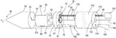
- FIG. 1is an illustrative perspective view of an embodiment of an ultrasound device in a disassembled configuration.
- FIG. 2is an illustrative cross-sectional view of the ultrasound device of FIG. 1 .
- FIG. 3is an illustrative perspective view of a slip ring assembly of the ultrasound device of FIG. 1 .
- FIG. 4is an illustrative perspective view of a stationary component of the FIG. 3 embodiment.
- FIG. 5is an illustrative front view of a rotational contact portion of the slip ring assembly of the FIG. 3 embodiment.
- FIG. 6is an illustrative perspective view of the rotational contact portion of FIG. 5 .
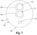
- FIG. 7is an illustrative end view of one embodiment of a pusher piece from the device of FIG. 1 .
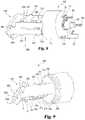
- FIG. 8is a perspective view of a portion of an embodiment of a three-dimensional ultrasound device in a first condition.
- FIG. 9is a perspective view of a portion of the device of FIG. 8 in a second condition.
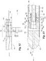
- FIG. 10is an illustrative cross-sectional view of a portion of an alternative embodiment of an ultrasound device having an isolated wire guide lumen.
- FIG. 11is an illustrative cross-sectional view of a portion of an alternative embodiment of an external motor having a hollow shaft and a hollow torque cable attached to the hollow shaft for use with an ultrasound device.
- FIG. 12is an illustrative cross-sectional view of a portion of an alternative embodiment of an external motor having a gear assembly attached thereof and a hollow torque cable for use with an ultrasound device.
- FIG. 13is an illustrative cross-sectional view of a portion of an alternative embodiment of an ultrasound device that is connectable to either embodiment illustrated in FIG. 11 or FIG. 12 .
- a device 20 for internal ultrasound proceduresSuch devices may be diagnostic or therapeutic (including interventional) in application, and include devices inserted percutaneously, subcutaneously or endoluminally into the patient.
- Device 20can be used with a system which includes a console (not shown) for processing data or signals received from an ultrasound transducer.
- the ultrasound consolecan be a type which is generally used for medical ultrasonic imaging, e.g. generally including control devices usable by a physician and a graphic display which displays graphical images obtained during an ultrasound procedure.
- the device 20is connectable to the console portion through standard connections.
- Device 20can be used for obtaining images at various locations and conduits of a body such as a blood vessel, urethra, ureter, vagina, rectum, throat, ear, or through an artificial tract by percutaneous puncture for example.
- Device 20is capable of transmitting and receiving ultrasound signals and then communicating data obtained from ultrasound signals to the console.
- device 20is shown in a disassembled configuration in which elements are illustrated with some distance between two elements. In an assembled configuration such that device 20 could be implanted in a patient's body, adjacent elements of device 20 will be positioned in contact with each other, as described in more detail below.
- device 20includes a catheter 22 or other flexible elongated or tubular member having a wall 24 and extending along a longitudinal axis L and a catheter tip 25 (or other tubular member) having a channel 30 and extending along the longitudinal axis L.
- Wall 24has an inner surface defining an internal chamber 26 , within which is included a mounting piece 29 housing a transducer 28 for sending and/or receiving ultrasound signals.
- catheter tip 25may have a port or other feature to allow injection of fluid into internal chamber 26 .
- the catheter tip 25includes a channel or through hole 30 configured to receive a wire guide 42 .
- the rotation axis R about which the transducer 28 rotatesis aligned or coincides with the longitudinal axis L along catheter 22 .
- transducer 28may also be pivoted about a pivot axis substantially transverse or perpendicular to the rotation axis R, allowing ultrasound emission to extend forward (axially relative to the rotation axis) and laterally (radially relative to the rotation axis). Therefore, transducer 28 is capable of transmitting and receiving ultrasound signals in a variety of directions or orientations which are passed along data signal communication lines between transducer 28 and the ultrasound console.
- Catheter 22 in the illustrated embodimentis an elongated device of plastic or other sturdy flexible material.
- catheter 22is sized and configured for insertion into and/or travel along bodily orifices or lumens.
- Catheter 22includes a control end which during use is nearest to the user and an application end which during use is nearest to the user's point of interest within the patient.
- control and applicationare used throughout this description to describe these positional orientations.
- Wall 24surrounds chamber 26 , which is near the application end of device 20 in the illustrated embodiment. The application end of wall 24 is sized and configured to receive and retain catheter tip 25 .
- the control end of wall 24 and/or catheter 22may extend outside of the patient during use, or may attach to another piece that extends outside the patient, and may end in a handle or other operating portion for maneuvering catheter 22 .
- the application side end of catheter tip 25is tapered in some embodiments, and in the particular illustrated embodiment is open at end 38 to an external area surrounding the catheter.
- the application end of the catheter 22is at least partially constructed of a material which has acoustic impedances similar to that of body fluids such as blood. Only the distal or control end of the catheter needs to be acoustically transparent, but more or all of catheter 22 may be made of the same material as wall 24 in some embodiments. Possible materials could include, for example, a polymer material such as polyethylene (PE), polymethylpentene (PMP), or acrylonitrile butadiene styrene (ABS).
- PEpolyethylene
- PMPpolymethylpentene
- ABSacrylonitrile butadiene styrene
- Transducer 28is indicated schematically in the drawings.
- the term “transducer”should be understood to include an assembly of two or more parts as well as a single piece. Embodiments of transducer 28 may be capable in particular examples of sending and receiving ultrasound waves in a range of frequencies which are typically used in medical ultrasound procedures, such as, for example, in the range from 20 kHz to 100 MHz.
- Transducer 28is operably linked to a motor 100 via a torque cable 60 to permit transducer 28 to turn, pivot, or otherwise move.
- “transducer” as used hereinincludes devices that transmit ultrasound signals (i.e. transform an electrical (RF) signal to ultrasound), receive ultrasound signals (i.e. transform ultrasound to an electrical (RF) signal), or both.
- RFelectrical
- Transducer(s) as described hereinmay have one or more piezoelectric elements as respective transducers, and may operate in combination with other transducers within or outside the body.
- “transducer” as used hereinincludes a split single element transducer on a rotating and/or pivoting member, a single element transducer on a rotating and/or pivoting member, or a one-dimensional array of elements on a rotating and/or pivoting member.
- Channel 30extends from the control end to the application end of the catheter 22 .
- channel 30ends at the application side 27 b of catheter tip 25 .
- the channel 30can be configured to accept varied sizes of wire guides, such as wire guides with diameters between 0.014′′ to 0.038′′.
- Channel 30is sized and configured to permit effective injection and travel of a coupling medium toward chamber 26 .
- mounting piece 29defines at least one passageway 66 extending from channel 30 to chamber 26 , such as the illustrated passageway 66 , which is configured to permit the transfer of coupling medium into chamber 26 .
- the passageway 66is in open communication with chamber 26 . In other embodiments, there may be greater or fewer than the one illustrated passageway defined in mounting piece 29 .
- passageway 66may be perpendicular to a bore 64 or the passageway 66 may be angled with respect to the channel 30 (axially with respect to rotation axis R), such that the passageway extends from the channel 30 to the chamber 26 in a direction generally from the control end to the application end of the catheter 22 .
- the passageway(s)may be oriented differently than as illustrated.
- Open end 38 of device 20allows gas to move from chamber 26 to the external area outside of device 20 during filling or charging of chamber 26 with coupling medium.
- a dedicated exhaust portmay be incorporated into the device and open end 38 may be absent.
- an amount of gas(es) or liquid(s)may enter through open end 38 from the external area outside of the device 20 during insertion and/or use of the device 20 , although the amount may be minimal, insubstantial or inconsequential to the use and operation of the device 20 .
- the diameter of the opening in end 38is slightly smaller than channel 30 .
- Device 20includes a slip ring assembly 50 and a hollow shaft 62 with the mounting piece 29 attached thereto as illustrated in FIG. 2 .
- Electronic signalspass between an ultrasound console and transducer 28 through both a stationary portion 49 and a rotating portion 51 which together form a slip ring assembly 50 .
- a motor 100is operatively connected with the shaft 62 or the mounting piece 29 while the rotating portion 51 of the slip ring assembly 50 is operatively connected with rotatable shaft 62 or the mount piece 27 and the stationary portion 49 with the gear base as described in more detail below.
- Slip ring assembly 50includes brush-style rotational contacts 52 , 54 and ring-shaped stationary contacts 56 , 58 .
- Rotatable shaft 62is a hollow cylindrical shaft having a lumen 63 extending therethrough.
- Transducer 28is operatively connected to shaft 62 via the mounting piece 29 so that transducer 28 rotates in response to rotation of shaft 62 .
- Mounting piece 29is a structure that is configured to support transducer 28 while providing additional functions.
- Various embodiments of the mounting piececan allow rotational motion of the transducer around a rotation axis, define part of a wire guide channel, and/or include a cavity for housing a transducer element as well as providing other features or functions as described herein.
- a bore 64extends along or substantially parallel to the rotation axis through mounting piece 29 and provides attachment to shaft 62 as well as defining a portion of the channel 30 or the lumen, which, in the illustrated embodiment is configured to accept a wire guide 42 .
- bore 64includes a side passageway 66 that extends through mounting piece 29 , which, in some embodiments can be used for fluid injection.
- mounting piece 29Another example of such mounting pieces is explained in U.S. Provisional Application No. 61/885,155 (filed Oct. 1, 2013 and entitled “Over-The-Wire Ultrasound System”), and in U.S. patent application Ser. No. 14/501,745 (filed Sep. 30, 2014 and entitled “Over-The-Wire Ultrasound System”), which are incorporated herein by reference in their entirety.
- Stationary contacts 56 , 58are part of a stationary mount piece 70 of slip ring assembly 50 .
- Stationary mount piece 70has a contact end 72 opposite a cable end 74 and a length that spans between contact end 72 and cable end 74 .
- Mounted to the stationary mount piece 70are the slip ring assembly 50 , a pin 75 , and shaft 62 that gears 77 and 79 , respectively, are mounted to.
- Stationary mount piece 70includes a bore 78 that spans between a contact end 72 and a cable end 74 , wherein the bore 78 is sized to receive the shaft 62 . As such, shaft 62 passes through bore 78 from the contact end 72 to the cable end 74 .
- the contact end 72is circular and is positioned at the control side of mounting piece 29 .
- Contact end 72is oriented so that stationary contacts 56 , 58 are positioned generally normal to the rotation axis.
- the cable end 74is circular and includes pin 75 that is positioned on a face of cable end 74 .
- Pin 75is sized to receive and retain a drive gear 77 that is connected to a torque cable 60 .
- Pin 75is located on the face of cable end 74 of the stationary mount piece 70 to enable coupling of the drive gear 77 to a ring gear 79 that is coupled with shaft 62 (see FIG. 1 ).
- the drive gear 77 and the ring gear 79are configured to interact with one another and are external gears, i.e., having teeth that point away from their axes of rotation. Alternate embodiments can include different interactive gears that do not include teeth, such as belt driven gears or friction gears, to name a few.
- the face of cable end 74also includes two contact pads 81 that are positioned opposite the pin 75 . Contact pads 81 are used to solder or weld transducer electrical wires 160 thereto.
- the pin 75 , bore 78 , and the contact pads 81are generally positioned in a lineal fashion on the face of the cable end 74 . As described in more detail below, the pin 75 , bore 78 , and the contact pads 81 are positioned to align with respective lumens 170 , 172 , and 174 in a pusher piece 176 .
- Stationary portion 49 of the stationary mount piece 70includes stationary contacts 56 , 58 in the illustrated embodiment ( FIGS. 3 and 4 ) is constructed from printed circuit board methods of manufacture including photolithography and etching.
- the stationary portion 49is constructed as a flexible printed circuit board and is layered, having alternating conductive hard-gold plated nickel or copper and insulative polyimide layers.
- a topmost conductive layer 80includes stationary contacts 56 , 58 . Wires (not illustrated) provide electrical connectivity between stationary contact 56 and contact pads 81 in cable end 74 .
- Beneath layer 80is an insulative layer 82 , which electrically isolates stationary portion 49 from other components.
- the conductive layer 80is electrically connected to contact pads 81 by a conductive path such as a wire or other means (not illustrated) through the stationary mount piece 70 and carries an electrical signal through the stationary mount piece 70 to contact pads 81 .
- the transducer electrical wires 160which include a coaxial cable or other suitable conductors ( FIG. 1 ) are attached to both contact pads 81 in cable end 74 to carry signals to the control end of device 20 .
- Rotational contacts 52 , 54are attached to mounting piece 29 in the illustrated embodiment.
- rotational contacts 52 , 54are individual metal pieces that are stamped or otherwise manufactured from the same sheet of metal as illustrated in FIGS. 5 and 6 .
- rotational contacts 52 , 54are two separate electrical lines.
- Rotational contact 52has two brush prongs 130 and a conductor prong 132 .
- rotational contact 54has two brush prongs 134 and a conductor prong 136 .
- Other embodimentsinclude more or less brush prongs as appropriate.
- rotational contacts 52 , 54are a flexible printed circuit board. In some embodiments, rotational contacts 52 , 54 are insert molded into mounting piece 29 . In other embodiments, rotational contacts 52 , 54 are integrated into mounting piece 29 using a hot embossing process or with a hot-staking process. In other embodiments, rotational contacts 52 , 54 may be configured as conductive traces positioned on or into mounting piece 29 using electroless plating of metalizable plastic and/or a laser direct structuring technique.
- the rotational contacts 52 , 54are designed to attach to transducer 28 or other rotating part of device 20 that is generally normal to the rotation axis (similar connection illustrated in FIGS. 8, 9, and 10 ).
- the connectionsare made through mounting piece 29 using laser direct structuring process (LDS) and/or electroless plating of metalizable regions of the plastic.
- LDSlaser direct structuring process
- tabs 128hold rotational contacts 52 and 54 relative to each other while the contacts are attached to mounting piece 29 using glue, fasteners, or another suitable attachment method. After rotational contacts 52 and 54 are attached to mounting piece 29 , tabs 128 are cut and removed so that rotational contact 52 is physically and electrically separated from rotational contact 54 .
- Mounting piece 29is constructed from (or coated wholly or partially with) an electrically insulative material so that it acts as an insulator between rotational contacts 52 and 54 .
- Conductor prongs 132 , 136are bent around mounting piece 29 and attached to transducer 28 to form the signal and ground channels, which are then connected to transducer 28 .
- Brush prongs 130are positioned to abut against and slide along stationary contact 56
- brush prongs 134are positioned to abut against and slide along stationary contact 58 .
- Brush prongs 130 , 134are bent to an angle to create a spring force when brush prongs 130 , 134 are positioned to abut against stationary contacts 56 , 58 .
- Contact end 72 of stationary mount piece 70is positioned generally normal to the rotation axis and parallel to the control side surface of mounting piece 29 that supports rotational contacts 52 , 54 .
- Rotational contacts 52 , 54include multiple brush prongs which also help to ensure stable connection.
- an elastically compressible polymeris used for the brush portion which is an elevated portion of mounting piece 29 with conductive traces printed/plated on top of the elevated regions that are configured to contact stationary contacts 56 , 58 .
- FIGS. 1, 2, and 3device 20 in FIGS. 1, 2, and 3 is depicted with mounting piece 29 positioned slightly away from stationary mount piece 70 so that rotational contacts 52 , 54 are not in contact with stationary contacts 56 , 58 .
- mounting piece 29is positioned close enough to stationary mount piece 70 to make functional electrical connections between the stationary contacts and rotational contacts such as in an assembled configuration.
- either or both of rotational contacts 52 , 54 and/or stationary mount piece 70has a finish layer that includes a layer or layers of beryllium copper, nickel, tin, gold, palladium, silver, hard gold (e.g. AuCo, AuNi, AuCoNi, etc.) or other noble metals and their alloys.
- the finish layeris designed to prevent corrosion in air or fluid as well as to not create debris within chamber 26 during use.
- the stationary contactscan include brush prongs and the rotational contacts can include planar surfaces configured to abut against the brush prongs.
- Other examples of slip ring designsare explained in International Application No. PCT/US2013/064611, filed on Oct. 11, 2013, published as WO 2014/059292 A1, and entitled “INTERNAL TRANSDUCER ASSEMBLY WITH SLIP RING”, which is hereby incorporated by reference in its entirety.
- pusher piece 176includes lumens 170 , 172 , and 174 that span between an application end 178 and a control end 180 .
- the application end 178includes a face 182 with a first recess 184 that extends substantially around the lumen 170 and a portion of lumen 172 .
- the first recess 184is sized to receive the drive gear 77 .
- the face 182also includes a second recess 186 that extends substantially around the lumen 172 and a portion of lumen 170 .
- the second recess 186is sized to receive the ring gear 79 .
- first recess 184 and the second recess 186are arranged and sized to collectively receive the drive gear 77 and the ring gear 79 , respectively.
- the pusher piece 176is butted up to the stationary mount piece 70 such that the drive gear 77 nests with the first recess 184 and the ring gear 79 nests with the second recess 186 .
- Lumen 170is sized to receive the torque cable 60 .
- lumen 170is reinforced to avoid abrasion of the torque cable 60 when the device 20 is being used.
- Lumen 172is sized substantially the same as the bore 78 to enable the wire guide 42 and fluid to pass through lumen 172 and into bore 78 for a fluid passageway. As such, fluid flushes into the mounting piece 29 and out the side passageway 66 to fill chamber 26 .
- lumen 172is sized to fit a metal or polymer tubing that seals between the wire guide 42 and the chamber 26 . In this embodiment, lumen 172 is sealed on the tip side and on the side of the stationary mount piece that is closer to the control end to contain the coupling fluid within chamber 26 .
- Lumen 174is sized to receive the transducer electrical wires 160 and the contact pads 81 .
- pusher piece 176is made of a flexible plastic rod.
- the pin 75 , bore 78 , and the contact pads 81are positioned to align with respective lumens 170 , 172 , and 174 in a pusher piece 176 .
- Lumens 170 , 172 , and 174maintain the torque cable 60 , wire guide 42 , and transducer electrical wires 160 , respectively, from becoming entangled with one another after assembly of the device 20 .
- Motor 100is mechanically connected with the torque cable 60 to operatively drive the gear 77 which drives the gear 79 that is connected to the shaft 62 .
- Shaft 62in turn drives the mounting piece 29 and the transducer 28 .
- the motor 100is placed remotely and will drive the mounting piece 29 and the transducer 28 via the long torque cable 60 .
- the motor 100is not placed within the catheter 22 but is positioned outside and a distance from the catheter 22 therefore the size of motor 100 may vary as desired.
- the motor 100is external to the catheter 22 and could be mounted on the handle or connected to the handle to transfer torque to the torque cable 60 . It could be any type of motor, electrically driven, pneumatically, or hydraulically driven. It could also be driven by the operator via a crank handle.
- motor 100turns the torque cable 60 about its longitudinal axis, which in turn drives or rotates the drive gear 77 .
- the drive gear 77is coupled to the ring gear 79 such that rotation of the drive gear 77 rotates ring gear 79 which in turn rotates mounting piece 29 that is connected to the ring gear 79 via the shaft 62 .
- rotating the torque cable 60in turn rotates the mounting piece 29 and the transducer 28 , albeit in the opposite direction.
- Motor 100may be configured to rotate torque cable 60 and thus mounting piece 29 continuously in a single rotational direction.
- transducer 28is rotated around the rotation axis in that single rotational direction.
- Appropriate feedback mechanismsmay be used to precisely control the rotational position of mounting piece 29 (and transducer 28 rotated by it) relative to the rest of device 20 , ensuring proper registration of images obtained through transducer 28 . Registration can be accomplished via methods and structures discussed in U.S. Provisional Application No. 61/713,142 (filed Oct. 12, 2012 and entitled “Feedback/Registration Mechanism for Ultrasound Devices”) which is incorporated by reference herein in its entirety.
- Motor 100may alternatively be configured to run in a reciprocating motion, with torque cable 60 switching between rotation in a first rotary direction (e.g. for a predetermined time, arc or number of turns) and rotation in a second, opposite, rotary direction (e.g. for a predetermined time, arc or number of turns).
- a first rotary directione.g. for a predetermined time, arc or number of turns
- a second, opposite, rotary directione.g. for a predetermined time, arc or number of turns.
- device 20is typically charged or injected with coupling medium prior to insertion into the patient's body, e.g. before a wire guide or other tool or structure is placed in channel 30 .
- chamber 26is pre-filled with coupling medium during production.
- device 20is inserted into the body of a patient, and/or maneuvered to a desired location (e.g. in a particular blood vessel).
- the device 20may be charged (or further filled or refilled) with coupling medium following insertion into the patient's body, or may occur during insertion and transducer 28 may be operated during travel to the desired location.
- filling or refillingcan be done with structure (e.g. wire guide 42 ) inside channel 30 , or with channel 30 otherwise empty.
- particular embodiments of catheter 22 or at least chamber 26are cylindrical, and are sized for insertion into and passage through body conduits.
- Appropriate coupling mediumis selected, such as saline, oils, alcohols or other appropriate ultrasound-transmissive fluids, so as to give chamber 26 ultrasound characteristics similar or substantially identical to that of wall 24 and the surrounding bodily environment (e.g. the blood stream).
- the coupling mediumis loaded into a syringe with a needle (not shown) or other appropriate injection, insertion or transfer device.
- Coupling mediummay be injected into channel 30 at or near the control end of the catheter 22 , or otherwise at an entry location into channel 30 , so as to urge the coupling medium to travel within channel 30 toward chamber 26 .
- the coupling mediummay be forced through the needle and into channel 30 via pressing a syringe plunger.
- motor 100Prior to, during and/or following injection of the coupling medium, motor 100 is activated to cause mounting piece 29 to rotate about the rotation axis R. Upon reaching mounting piece 29 , the coupling medium is urged into the passageway 66 and out into chamber 26 by centrifugal action or inertial force as a result of rotation of mounting piece 29 about the rotation axis R.
- the coupling mediumAs the coupling medium enters the chamber 26 , it displaces the gas within chamber 26 by increasing the pressure on such gas (e.g. air). The increased pressure forces the gas out of chamber 26 through open end 38 to the external area outside of device 20 . Injection of coupling medium continues until chamber 26 is filled to a satisfactory degree, for example when a predetermined amount of medium has been injected, and/or a maximum amount of the gas previously in chamber 26 has been replaced with coupling medium. As a result, the chamber 26 is filled with coupling medium to an extent that there are no visible gas pockets or bubbles present around transducer 28 , as gas pockets or bubbles have an acoustic impedance significantly different from the coupling medium, and thus can reflect or otherwise attenuate ultrasound waves.
- gase.g. air
- the charging and exhaust effects occurring with respect to the illustrated devicedo not require space within the wall 24 of catheter 22 , as is needed for the placement of other types of tubes or ports required for charging. Such space considerations can be quite important for uses of ultrasound in small areas, such as cardiovascular (e.g. peripheral vascular) applications.
- the illustrated arrangementalso provides the ability to flush the catheter with and/or add coupling medium from an access at or near the control end and while the catheter is in situ, if deemed necessary by the medical professional.
- Motor 100may be operated to turn transducer 28 around the rotation axis R to provide the desired imaging at one or more different times throughout the procedure.
- the transducer 28may be rotated during injection of the coupling medium, during travel and placement of the catheter, and/or at the final desired imaging location.
- the option of providing imaging while coupling medium is injected into the device and enters the chamber 26allows the user to evaluate the fill status of the chamber 26 and determine when complete fluid coupling occurs.
- the user consolemay be configured to provide notifications to the user indicating the fill status of the chamber 26 and/or indicating the presence of gas pockets or bubbles, or providing indications of other issues pertaining to the user of the device.
- motor 100can be operated to turn transducer 28 around the rotation axis R to provide images of tissue(s) or other matter around device 20 , and in certain optional embodiments to pivot the transducer about a pivot axis.
- the ultrasound signalpasses through wall 24 of catheter 22 until it encounters an acoustic impedance boundary (e.g. body tissue, plaque, medical implant, or other material which has acoustic impedance sufficiently different from bodily fluids or other surrounding material) such that the ultrasound signal is at least partially reflected at the boundary. At least a portion of the ultrasound signal is reflected back towards transducer 28 .
- an acoustic impedance boundarye.g. body tissue, plaque, medical implant, or other material which has acoustic impedance sufficiently different from bodily fluids or other surrounding material
- One or more electrical signals representing reflected ultrasound received at transducer 28are sent from transducer 28 via a conduction pathway to the ultrasound console, for imaging and/or other data display to the physician. Simultaneously or subsequently transducer 28 continues to emit further ultrasound signals and the process is repeated continuously in certain embodiments and over a desired period of time. Controls for motor 100 may be provided to maintain rotational motion of transducer 28 about the rotation axis at a particular rotational speed or pattern. Imaging continues, with adjustments to the positioning of transducer 28 and the ultrasound field, as the physician deems necessary or useful. Once the desired therapeutic, diagnostic, imaging or other ultrasound procedure is performed, the device can be removed.
- Catheter 22has at least a portion that presents a minimal barrier to the passage of ultrasound signals so that ultrasound images of surrounding matter (e.g. tissue(s) or implant(s)) may be reasonably acquired through the barrier.
- catheter 22may have at least a portion that is constructed of a material which is substantially echolucent (i.e. having small ultrasound attenuation, having similar acoustic impedance or small difference in acoustic impedance with the surrounding environment) when placed in the surrounding working environment, such that it acts as an acoustic window which allows passage of ultrasound signals with minimal reflection. It will be understood that only the application end of catheter 22 (e.g.
- catheter 22need be acoustically transparent, but more or all of catheter 22 and/or other components thereof may be made of the same material in some embodiments.
- catheter 22when used within a body conduit containing body tissues and blood, it is preferable for catheter 22 to be constructed of a material which is structurally rigid and which has acoustic impedance similar to that of body fluids such as blood.
- Possible materialscould include, for example, a polymer material such as high density polyethelene, polymethylpentene (PMP), or acrylonitrile butadiene styrene (ABS). It has been determined that in some cases the thickness of at least the portion of catheter 22 which serves as the viewing window can be approximately N/2 (where N is a positive integer) of the wavelength corresponding to the center frequency of the ultrasound signal.
- Device 20could also be used for a variety of other medical procedures and with a variety of other medical devices. Accordingly, the particular methods of use described herein are not indicative of any limiting aspects of the usage capabilities of device 20 .
- FIGS. 8 and 9represent an alternate embodiment of structure of a device 220 for internal ultrasound procedures.
- This embodiment of device 220includes a transducer 228 , pivoting mechanism 230 , a first torque cable 60 , a second torque cable 162 , a coaxial cable 171 , and one or more slip disk connection pads 173 .
- the features of device 220are intended in particular embodiments to be housed within a catheter, essentially as described above with respect to device 20 and catheter 22 .
- Torque cable 60connects to drive gear 77 which is mounted on pin 75 , similarly as described above. Ring gear 79 is coupled with shaft 62 wherein drive gear 77 and ring gear 79 are configured and positioned to interact with one another as described above. Torque cable 60 is connected to drive gear 77 wherein the torque cable 60 causes the drive gear 77 to rotate to thereby rotate the ring gear 79 to rotate the shaft 62 and the transducer 228 .
- a through shaft 161passes through shaft 62 and stationary mount piece 70 to a threaded shaft 280 . There is some clearance between through shaft 161 and shaft 62 so that shaft 62 can rotate without coming in contact with through shaft 161 .
- through shaft 161 and threaded shaft 280are a single component.
- Shaft 280passes through hollow shaft 62 with a portion of the distal end of shaft 280 extending beyond the end of shaft 62 .
- shaft 280is threaded over its entire length, while in other embodiments shaft 280 may be threaded only over one or more discrete portions, e.g. a portion that passes through hollow shaft 62 and extends beyond hollow shaft 62 .
- shaft 280may be threaded only over one or more discrete portions.
- Shaft 280is able to turn within and independently of shaft 62 .
- the rate of rotation of torque cable 162controls the rate of rotation of threaded shaft 280 .
- Transducer 228is similar to transducer 28 .
- Transducer 228is mounted in pivoting mechanism 230 to permit transducer 228 to turn around a rotating axis as well as pivot around a pivoting axis.
- the illustrated embodiment of mechanism 230is a gimbal-type mounting, having an outer frame piece or base 250 including a center portion 252 with a hole 254 therethrough and matching arms 256 extending laterally of hole 254 from center portion 252 .
- Center portion 252is fixed to or with respect to shaft 62 so that shaft 62 can turn pivoting mechanism 230 .
- Hole 254is sized and configured to threadedly accommodate a portion of shaft 280 .
- a pivoting element 258fits into holes 260 in arms 256 in the embodiment of FIGS. 8 and 9 .
- Pivoting element 258 in the illustrated embodimentis a circular disk 262 having side ears or pivot points 264 that fit into holes 260 and act as an axle, so that element 258 can pivot around the axis defined by ears 264 .
- pivoting element 258may be a backing, base or substrate on which all or a part of transducer 228 is fixed, or may be a portion of transducer 228 .
- Mechanism 230 in this embodimentincludes a sliding member or plate 310 in contact with arms 256 .
- Plate 310has respective lateral sides 311 in this embodiment each having top and bottom grooves 312 .
- Arms 256 of mechanism 230are within grooves 312 of sliding member or plate 310 , so that plate 310 can slide along the arms, moving linearly with respect to mechanism 230 .
- Plate 310includes an opening 313 therethrough, which in the illustrated embodiment is substantially in the center of Plate 310 .
- Plate 310may be thin so that the rim or edge of opening 313 acts as a thread that is compatible with the thread of shaft 280 , or the rim or edge of opening 313 may be internally threaded so as to engage the threads of threaded shaft 280 .
- the range of movement of plate 310 along arms 256is defined by limit stops 331 on the arms of the pivoting mechanism 230 .
- Limit stops 331are shown in this embodiment as raised portions or bosses extending from the arms, e.g. a square or rectangular tab in the plane of and monolithic with the arm 256 .
- the sites of limit stops 331determine the maximum amount of movement of plate 310 by creating a location relative to arms 256 at which plate 310 is blocked from further sliding along arms 256 .
- limit stops 331are placed only at a location distal of center portion 252 , so that plate 310 can slide at most between center portion 252 (acting as a control-side limit stop) and limit stops 331 , while in other embodiments a set of limit stops 331 may be placed inside center portion 252 and another set of limit stops 331 further distally.
- Part or all of plate 310 and/or of arms 256can be made from or coated with a low friction material (e.g. PTFE (Teflon)) to make the sliding of plate 310 over arms 256 easier.
- a low friction materiale.g. PTFE (Teflon)
- plate 310Because plate 310 is connected to arms 256 , it rotates along with pivoting mechanism 230 at a rate of speed that is determined by the rotation of shaft 62 by torque cable 162 . Plate 310 is also threadedly connected to shaft 280 , as threads of shaft 280 engage plate 310 through opening 313 . The rate of rotation of threaded shaft 280 is determined by torque cable 162 .
- a forcing member 360is attached to plate 310 , and in the illustrated embodiment member 360 is connected to pivoting element 258 on one end and to the side of the pivoting axis.
- pivoting element 258can include a tab T that extends from pivoting element 258 opposite (e.g. substantially perpendicular) from transducer 228 .
- Forcing member 360can include a distal finger F that connects to tab T, as by extending through a hole or slot in tab T (e.g. FIGS. 8 and 9 ), so that member 360 can pivot with respect to tab T.
- forcing member 360attached to plate 310 and connected to pivoting element 258 , movement of plate 310 causes the forcing member 360 to apply force to pivoting element 258 , which rotates pivoting element 258 (with transducer 228 ) around the axis defined by ears 264 .
- Forcing member 360 in the illustrated embodimentis a flattened bar that preferably has little or no longitudinal elasticity, so that movement of plate 310 is efficiently transmitted to pivoting element 258 .
- a suitable forcing membermay be of other shapes or materials that provide for transmission of enough force to pivot element 258 when sliding plate 310 moves along arms 256 , such as a C-shaped wire structure or similar member described above.
- Mechanism 230permits transducer 228 to turn around a rotating (e.g. longitudinal) axis, via transmission of rotational motion from torque cable 60 to mechanism 230 via shaft 62 .
- Mechanism 230permits pivoting of transducer 228 around a pivoting axis (e.g. perpendicular to the rotating axis) at the same time, via pulling or pushing force on pivoting element 258 transmitted via member 360 from sliding plate 310 .
- Plate 310is moved along arms 256 when the rotational speed of threaded shaft 280 is different from the rotational speed of shaft 62 , so that a nonzero rotational speed of shaft 280 relative to shaft 62 exists. In the latter case, the threaded engagement of shaft 280 and plate 310 causes plate 310 to slide along arms 256 . Pivoting element 258 is thus able to rotate about both the pivoting and axial directions.
- plate 310moves in a one linear direction along arms 256 (either toward or away from base 250 ), and pivots element 258 in one angular direction (either clockwise or counterclockwise).
- the speed of shaft 280is less than V (i.e. between V and V-v or at V-v)
- plate 310moves in the other linear direction along arms 256 , and pivots element 258 in the other angular direction.
- pivoting element 258it is possible to arrange pivoting of pivoting element 258 from a first position that is substantially forward-looking (e.g. FIG. 8 ), so that transducer 228 points along or substantially along a longitudinal axis of device 220 , to a second position that is somewhat rearward-looking, so that transducer 228 points in a direction more than 90 degrees behind that forward-looking first position (i.e., past perpendicular to the longitudinal axis).
- Device 220thus has the ability to look forward using ultrasound, as well as having a very wide angle and volume of available viewing through ultrasound transmission. Further details regarding the motion mechanism are described in International Application No. PCT/US2013/064570 filed on Oct. 11, 2013 and published as WO 2014/059292, which is incorporated by reference.
- FIG. 10represents an alternate embodiment of a device 420 for internal ultrasound procedures.
- This embodiment of device 420includes similar features as device 20 .
- Device 420includes a catheter 422 similar to catheter 22 having a wall 424 and extending along a longitudinal axis L and a catheter tip 425 having a wall 427 and extending along the longitudinal axis L.
- Wall 424has an inner surface defining an internal chamber 426 , within which is included a mounting piece 429 housing a transducer 428 .
- Wall 424surrounds chamber 426 which is near the application end of the device 420 .
- the application end of wall 424is sized and configured to receive and retain catheter tip 425 .
- chamber 426is pre-filled with a coupling medium during manufacture of device 420 .
- Cannula 440extends a partial or full length of channel 430 .
- Cannula 440contains the wire guide lumen, and allows for the wire guide lumen to be isolated from chamber 426 , which allows for chamber 426 to be pre-filled with coupling medium during manufacturing of device 420 .
- Transducer 428is similar to transducer 28 therefore for the sake of brevity will not be described again.
- Transducer 428is operably linked to a motor (positioned exterior to the catheter 422 ) via a torque cable 460 to permit transducer 428 to turn, pivot, or otherwise move.
- a channel 430extends from the control end to the application end of the catheter 422 .
- Channel 430includes a tubular opening 431 sized to receive a cannula 440 sized and configured to receive a wire guide 442 .
- the cannula 440is configured to seal the chamber 426 to block any fluid in the chamber 426 from entering or contacting the wire guide 442 inside cannula 440 .
- a sealis formed near a stationary mount piece 470 and with the cannula 440 .
- the chamber 426is completely sealed off from the rest of the catheter 422 and can be pre-filled during production with oil or other non-corrosive and biocompatible coupling mediums and then the chamber 426 is sealed closed.
- mounting piece 429does not include a passageway to chamber 426 for filling the chamber 426 as in FIGS. 1 and 2 .
- Cannula 440is an elongated structure such as a metal tube or polymer or plastic tubing having a lumen to receive the wire guide 442 wherein the cannula 440 passes through catheter tip 425 , mounting piece 429 , a hollow shaft 462 , and a slip ring assembly 450 .
- Cannula 440can be configured to accept varied sizes of wire guides and align with channel 430 . In the illustrated embodiment, cannula 440 is positioned in channel 430 .
- Device 420includes a slip ring assembly 450 and a hollow shaft 462 similar to slip ring assembly 50 and hollow rotatable shaft 62 , respectively, discussed above.
- Slip ring assembly 450includes a stationary portion 449 and a rotating portion 451 .
- a motor(not illustrated) positioned exteriorly to the wall 424 is operatively connected with rotatable shaft 462 or the mounting piece 429 while the rotating portion 451 of the slip ring assembly 450 is operatively connected with the mounting piece 429 and the stationary portion 449 with the gear base.
- Slip ring assembly 450includes brush-style rotational contacts and ring-shaped contacts as described above.
- Rotatable shaft 462is a hollow cylindrical shaft having a lumen 463 extending therethrough.
- Transducer 428is operatively connected to shaft 462 via the mounting piece 429 so that transducer 428 rotates in response to rotation of the shaft 462 .
- a bore 464 similar to bore 64extends along or substantially parallel to the rotation axis through mounting piece 429 and provides attachment to the shaft 462 . Bore 464 is also sized to receive cannula 440 therein; however, cannula 440 does not rotate.
- a stationary mount piece 470is similar to stationary mount piece 70 described above and includes a contact end 472 opposite a cable end 474 and a length that spans between contact end 472 and cable end 474 .
- Mounted to the stationary mount piece 470are the slip ring assembly 450 , a pin 475 , and shaft 462 that gears 477 and 479 , respectively, are mounted to.
- Stationary mount piece 470includes a bore 478 that spans between contact and cable ends and is sized to receive the shaft 462 wherein the shaft 462 passes through bore 478 .
- Another important feature of the joint between the bore 478 in stationary mount piece 470 and shaft 462is that this joint is a bearing surface in order to allow shaft 462 to rotate with minimal friction.
- the cable end 474includes a pin 475 similar to pin 75 .
- Pin 475is sized to receive and retain a drive gear 477 that is connected to a torque cable 460 .
- Pin 475is located on the face of the cable end 474 to enable coupling of the drive gear 477 to a ring gear 479 that is coupled with shaft 462 .
- the drive gear 477 and the ring gear 479are configured to interact with one another and are external gears.
- a coaxial cable 560 or other suitable conductoris electrically connected with stationary portion 449 to carry signals to the control end of the device 420 .
- Stationary portion 449 of the stationary mount piece 470is similar to the stationary portion 49 described above.
- Rotational contacts 452 , 454are similar to rotational contacts 52 , 54 and are attached to the mounting piece 429 . Therefore similar features for stationary portion 449 and stationary mount piece 470 will not be described again.
- device 420 in FIG. 10is depicted with mounting piece 429 positioned slightly away from stationary mount piece 470 .
- mounting piece 429is positioned close enough to stationary mount piece 470 to make functional electrical connections between the stationary contacts and rotational contacts such as in an assembled configuration.
- a pusher piece similar to pusher piece 176 described abovemay be used with catheter 422 ; however, the pusher piece not shown in this embodiment.
- a motor(not illustrated) is connected with torque cable 460 to operatively drive gear 477 which drives gear 479 that is connected to the shaft 462 .
- Shaft 462in turn drives the mounting piece 429 and the transducer 428 .
- the motoris placed remotely and is positioned outside catheter 422 .
- the motor for embodiment illustrated in FIG. 10is similar to motor 100 discussed above.
- gear 477As gear 477 rotates, gear 477 causes gear 479 to also rotate to thereby transfer rotation from a central axis in gear 477 to a central axis in gear 479 , in other words, from an axis off center of the rotation axis of the transducer 428 to the central axis or channel 430 of the catheter 422 .
- the chamber 426is filled with coupling medium and then sealed such that the coupling medium does not leak out of it.
- FIG. 11represents an alternate embodiment of an external motor 600 with a hollow shaft 602 operably attached to the motor 600 for use with a hollow torque cable and an over the wire catheter as described above and in FIG. 13 .
- the motor 600includes the hollow shaft 602 .
- Other embodimentsmay not include the hollow shaft 602 but instead include an alternative connection between the motor 600 and the hollow torque cable 604 .
- the hollow shaft 602defines a lumen 605 that is sized to receive a wire guide 608 therein and a wall 607 that surrounds the lumen 605 wherein the wall 607 has a thickness and a length that is sufficient to receive and retain a distal end of the hollow torque cable 604 thereon.
- the hollow shaft 602is operably connected to a hollow torque cable 604 such that the torque cable 604 is driven directly by the hollow shaft 602 and the motor 600 .
- the hollow torque cable 604includes a lumen 606 sized and configured to receive the wire guide 608 therein. As such the wire guide 608 passes through the lumen 605 of the hollow shaft 602 and the lumen 606 of the hollow torque cable 604 .
- the hollow torque cable 604includes a distal end 610 opposite a proximal end (not illustrated) wherein the proximal end is operably connected to a hollow shaft 862 illustrated in FIG. 13 and described more below.
- FIG. 12represents an alternate embodiment of an external motor 700 with a solid shaft 702 operably attached to the motor 700 for use with an over the wire catheter as described above and in FIG. 13 .
- the solid shaft 702has a cylindrical shape and a solid cross-section.
- the shaft 702includes an alternative configuration that may be hollow.
- Mounted onto the shaft 702is a gear assembly 704 that includes a first gear 706 rotatably mounted onto the shaft 702 and a second gear 708 operably connected to the first gear 706 as described below.
- the gear assembly 704includes a first peg 710 mounted on a first face of the second gear 708 and a second peg 712 mounted on a second face of the second gear 708 .
- the first peg 710 or the second peg 712enables a first connection between the second gear 708 and a stationary piece 722 and a second connection between the second gear 708 and a hollow torque cable 709 .
- the first peg 710 and the second peg 712can include a pin, a dowel, or some other type of connector element.
- the first gear 706 and the second gear 708are configured and arranged to have an interactive relationship wherein the first gear 706 drives or moves the second gear 708 when the motor 700 is activated.
- the first gear 706 and the second gear 708are configured to interact with one another and are external gears, i.e., having teeth that point away from their axes of rotation. Alternate embodiments can include different interactive gears that do not include teeth, such as belt driven gears or friction gears, to name a few.
- the first gear 706is positioned adjacent to or offset a distance from a longitudinal axis L such that the first gear 706 has a rotational axis offset from the longitudinal axis L and the first gear 706 is rotatable about the rotational axis.
- the second gear 708is positioned along the longitudinal axis L of the housing and the second gear 708 is configured to interact with the first gear 706 wherein the second gear 708 , including the first peg 710 and the second peg 712 , is rotatable about the longitudinal axis L when the first gear 706 rotates about the rotational axis.
- the second gear 708defines a lumen 714 that is aligned with a lumen 716 on the first peg 710 and a lumen 718 on the second peg 712 .
- the lumens 714 , 716 , and 718are configured and aligned to receive a wire guide 720 therein.
- the first peg 710 and the second peg 712each have a cylindrical shape.
- the first peg 710has the same length and cross-sectional shape and size as the second peg 712 .
- the first peg 710can have a different length or cross-sectional shape than the second peg 712 .
- the first peg 710 and/or the second peg 712can be monolithic with the second gear 708 .
- the motor 700also includes a stationary piece 722 that is mounted or attached to the motor 700 .
- the stationary piece 722defines a first lumen or hole 724 that is sized to receive the wire guide 720 therein.
- the stationary piece 722also defines a second lumen or hole 726 that is sized and configured to retain a portion of the first peg 710 therein.
- the second lumen 726forms a bearing surface for the first peg 710 to enable rotation of the first peg 710 within the second lumen 726 when the second gear 708 rotates.
- the first lumen 724has a diameter that is smaller than a diameter of the second lumen 726 .
- the hollow torque cable 709is attached to the second peg 712 and is configured to receive the wire guide 720 therein.
- the shaft 702in turn causes the first gear 706 to rotate.
- Rotation of the first gear 706causes rotation of the second gear 708 and the first and the second pegs 710 and 712 .
- Rotation of the first peg 710causes the hollow torque cable 709 to rotate.
- second gear 708also rotates to thereby transfer rotation from a central or rotational axis in first gear 706 to a central axis in second gear 708 , in other words, from an axis off center of the rotation axis of the motor 700 to the central or longitudinal axis L of the housing.
- FIG. 13represents an alternate embodiment of a device 820 for internal ultrasound procedures that can be used with either the FIG. 11 or the FIG. 12 embodiments.
- This embodiment of device 820includes similar features as device 420 .
- Device 820includes a catheter 822 similar to catheter 422 having a wall 824 and extending along a longitudinal axis L and a catheter tip 825 having a wall 827 and extending along the longitudinal axis L.
- Wall 824has an inner surface defining an internal chamber 826 , within which is included a mounting piece 829 housing a transducer 828 .
- Wall 824surrounds chamber 826 which is near the application end of the device 820 .
- the application end of wall 824is sized and configured to receive and retain a catheter tip 825 .
- a coupling mediumis flushed into the chamber 826 from the handle end of the device 820 .
- Transducer 828is similar to transducer 28 therefore for the sake of brevity will not be described again.
- Transducer 828is operably linked to the motor 600 or 700 (positioned exterior to the catheter 822 ) via the torque cable 604 or 709 to permit transducer 828 to turn, pivot, or otherwise move.
- a channel 830extends from the control end to the application end of the catheter 822 .
- Channel 830is sized and configured to receive the wire guide 608 (or the wire guide 720 ).
- the chamber 826is filled with a coupling medium from the control end of the catheter 822 .
- Device 820includes a slip ring assembly 850 and a hollow shaft 862 similar to slip ring assembly 450 and hollow shaft 462 , respectively, discussed above.
- Slip ring assembly 850includes a stationary portion 849 and a rotating portion 851 .
- the motor 600 or 700 positioned exteriorly to the wall 824is operatively connected with the rotatable shaft 862 or the mounting piece 829 while the rotating portion 851 of the slip ring assembly 850 is operatively connected with the mounting piece 829 and the stationary portion 849 with the gear base.
- Slip ring assembly 850includes brush-style rotational contacts and ring-shaped contacts as described above.
- Rotatable shaft 862is a hollow cylindrical shaft having a lumen 863 extending therethrough and an outer surface 865 .
- the lumen 863is sized to receive and retain the application end of the hollow torque cable 604 or 709 therein.
- the outer surface 865 of the shaft 862may be sized and configured to receive and retain the application end of the hollow torque cable 604 or 709 thereon.
- the hollow torque cable 604 or 709connects directly with the rotatable shaft 862 .
- Transducer 828is operatively connected to the shaft 862 via the mounting piece 829 so that transducer 828 rotates in response to rotation of the shaft 862 .
- a bore 864 similar to bore 464extends along or substantially parallel to the rotation axis through mounting piece 829 and provides attachment to the shaft 862 .
- a stationary mount piece 870includes a contact end 872 opposite a cable end 874 and a length that spans between the contact end 872 and the cable end 874 .
- Mounted to the stationary mount piece 870is the slip ring assembly 850 .
- Stationary mount piece 470includes a bore 878 that spans between the contact end 872 and the cable end 874 and is sized to receive the shaft 862 wherein the shaft 862 passes through bore 878 .
- a bearing surfaceis located between the bore 878 and the shaft 862 to allow the shaft 862 to rotate with minimal friction.
- a coaxial cable 880 or other suitable conductoris electrically connected with stationary portion 849 to carry signals to the control end of the device 820 .
- Stationary portion 849 of the stationary mount piece 870is similar to stationary portion 449 described above.
- Rotational contacts 852 , 854are similar to rotational contacts 452 , 454 and are attached to the mounting piece 829 . Therefore similar features for stationary portion 849 and stationary mount piece 870 will not be described again.
- device 820 in FIG. 13is depicted with mounting piece 829 positioned slightly away from stationary mount piece 470 .
- mounting piece 829is positioned close enough to stationary mount piece 870 to make functional electrical connections between the stationary contacts and rotational contacts such as in an assembled configuration.
- a motor such as the motor 600 or 700is connected with the torque cable to operatively drive the shaft 862 .
- motor 600 illustrated in FIG. 11is connected to the device 820
- the torque cable 604operatively connects directly to the shaft 862 and to the motor 600 .
- the gear assembly 704drives the torque cable 709 as described above.
- rotation(with respect to the rotation axis and motion about the pivot axis as well as generally), it should be understood that even though rotation often implies an angle change much greater than 360°, the devices disclosed herein may be configured in certain embodiments so that the rotational angle may rotate through angles less than 360°.
- the term “pivot”may be considered by some more natural than “rotate” or vice versa, but for the purposes of this application the terms “rotate” and “pivot” are used for clarity to indicate the axis about which a change in angle occurs, not the nature or magnitude of the angle change.
Landscapes
- Life Sciences & Earth Sciences (AREA)
- Health & Medical Sciences (AREA)
- Biomedical Technology (AREA)
- Biophysics (AREA)
- Nuclear Medicine, Radiotherapy & Molecular Imaging (AREA)
- Pathology (AREA)
- Radiology & Medical Imaging (AREA)
- Engineering & Computer Science (AREA)
- Physics & Mathematics (AREA)
- Heart & Thoracic Surgery (AREA)
- Medical Informatics (AREA)
- Molecular Biology (AREA)
- Surgery (AREA)
- Animal Behavior & Ethology (AREA)
- General Health & Medical Sciences (AREA)
- Public Health (AREA)
- Veterinary Medicine (AREA)
- Ultra Sonic Daignosis Equipment (AREA)
Abstract
Description
Claims (14)
Priority Applications (1)
| Application Number | Priority Date | Filing Date | Title |
|---|---|---|---|
| US15/221,729US11317892B2 (en) | 2015-08-12 | 2016-07-28 | Over-the-wire ultrasound system with torque-cable driven rotary transducer |
Applications Claiming Priority (2)
| Application Number | Priority Date | Filing Date | Title |
|---|---|---|---|
| US201562203983P | 2015-08-12 | 2015-08-12 | |
| US15/221,729US11317892B2 (en) | 2015-08-12 | 2016-07-28 | Over-the-wire ultrasound system with torque-cable driven rotary transducer |
Publications (2)
| Publication Number | Publication Date |
|---|---|
| US20170042508A1 US20170042508A1 (en) | 2017-02-16 |
| US11317892B2true US11317892B2 (en) | 2022-05-03 |
Family
ID=56799581
Family Applications (1)
| Application Number | Title | Priority Date | Filing Date |
|---|---|---|---|
| US15/221,729Active2037-11-05US11317892B2 (en) | 2015-08-12 | 2016-07-28 | Over-the-wire ultrasound system with torque-cable driven rotary transducer |
Country Status (2)
| Country | Link |
|---|---|
| US (1) | US11317892B2 (en) |
| WO (1) | WO2017027690A1 (en) |
Families Citing this family (7)
| Publication number | Priority date | Publication date | Assignee | Title |
|---|---|---|---|---|
| EP3531920A1 (en)* | 2016-10-27 | 2019-09-04 | Koninklijke Philips N.V. | Inner member for intravascular imaging device and associated devices,systems, and methods |
| US9833256B1 (en)* | 2016-12-14 | 2017-12-05 | Ethicon Endo-Surgery, Llc | Ultrasonic surgical instrument with transducer slip joint |
| CN112384148B (en)* | 2018-07-10 | 2025-04-04 | 皇家飞利浦有限公司 | Wire connections in ultrasound imaging devices, systems and methods |
| JP7147079B2 (en)* | 2019-05-17 | 2022-10-04 | ボストン サイエンティフィック サイムド,インコーポレイテッド | Medical imaging device and system |
| US20220087648A1 (en)* | 2020-09-18 | 2022-03-24 | B-K Medical Aps | 3-D Endocavity Ultrasound Probe with a Needle Guide |
| US20220287679A1 (en)* | 2021-03-09 | 2022-09-15 | OneProjects Design and Innovation Ltd. | Disposable catheter with rotatable image array |
| CN114246675A (en)* | 2022-01-24 | 2022-03-29 | 微亚医疗科技(苏州)有限公司 | Power unit for vascular interventional surgery robot |
Citations (126)
| Publication number | Priority date | Publication date | Assignee | Title |
|---|---|---|---|---|
| US2790095A (en) | 1952-03-06 | 1957-04-23 | Philips Corp | Device for converting rotary motion into reciprocating motion or conversely |
| US4421118A (en) | 1981-08-12 | 1983-12-20 | Smithkline Instruments, Inc. | Ultrasonic transducer |
| US4637256A (en) | 1983-06-23 | 1987-01-20 | Matsushita Electric Industrial Co., Ltd. | Ultrasonic probe having dual-motion transducer |
| US4720266A (en) | 1985-03-27 | 1988-01-19 | Micro-Mega S.A. | Dental treatment device |
| US4785816A (en) | 1985-01-14 | 1988-11-22 | Johnson & Johnson Ultrasound Inc. | Ultrasonic transducer probe assembly |
| US4811617A (en) | 1988-02-01 | 1989-03-14 | Whiteman Marvin E Jr | Unidirectional to bidirectional angular displacement conversion apparatus |
| US4834102A (en) | 1988-02-25 | 1989-05-30 | Jack Schwarzchild | Endoscope for transesophageal echocardiography |
| US4895158A (en)* | 1986-07-07 | 1990-01-23 | Matsushita Electric Industrial Co., Ltd. | Ultrasonic probe |
| US4930515A (en) | 1988-10-04 | 1990-06-05 | Diasonics, Inc. | Ultrasound probe with multi-orientation tip-mounted transducer |
| US4951677A (en) | 1988-03-21 | 1990-08-28 | Prutech Research And Development Partnership Ii | Acoustic imaging catheter and the like |
| US4972839A (en) | 1988-12-22 | 1990-11-27 | Angelsen Bjorn A J | Miniaturized mechanically-steerable ultrasonic probe |
| JPH03215252A (en) | 1990-01-22 | 1991-09-20 | Toshiba Corp | Mechanical ultrasonic diagnostic apparatus |
| US5168878A (en) | 1990-04-06 | 1992-12-08 | Kabushiki Kaisha Toshiba | Mechanical scan type ultasonic probe |
| US5176141A (en) | 1989-10-16 | 1993-01-05 | Du-Med B.V. | Disposable intra-luminal ultrasonic instrument |
| US5181514A (en) | 1991-05-21 | 1993-01-26 | Hewlett-Packard Company | Transducer positioning system |
| JPH05154150A (en) | 1991-12-06 | 1993-06-22 | Aloka Co Ltd | Ultrasonic probe for intra-body cavity use |
| US5237884A (en) | 1991-04-22 | 1993-08-24 | Osada Research Institute, Ltd. | Power transmission device |
| US5240003A (en) | 1989-10-16 | 1993-08-31 | Du-Med B.V. | Ultrasonic instrument with a micro motor having stator coils on a flexible circuit board |
| JPH05269133A (en) | 1992-03-26 | 1993-10-19 | Toshiba Corp | Ultrasonic probe |
| JPH06209939A (en) | 1993-01-18 | 1994-08-02 | Fuji Photo Optical Co Ltd | Ultrasonic probe |
| US5373845A (en) | 1992-05-22 | 1994-12-20 | Echo Cath, Ltd. | Apparatus and method for forward looking volume imaging |
| US5377682A (en)* | 1991-09-05 | 1995-01-03 | Matsushita Electric Industrial Co., Ltd. | Ultrasonic probe for transmission and reception of ultrasonic wave and ultrasonic diagnostic apparatus including ultrasonic probe |
| US5377685A (en) | 1993-12-17 | 1995-01-03 | Baylis Medical Company, Inc. | Ultrasound catheter with mechanically steerable beam |
| WO1995019143A1 (en) | 1994-01-14 | 1995-07-20 | Paul G. Yock And Robert J. Siegel, A Joint Venture | Ultrasonic ablation of stenoses and occlusions with imaging guidance |
| US5437283A (en) | 1992-12-11 | 1995-08-01 | Tetrad Corporation | Endosurgical ultrasonic probe with integrated biopsy actuator |
| US5485845A (en) | 1995-05-04 | 1996-01-23 | Hewlett Packard Company | Rotary encoder for intravascular ultrasound catheter |
| US5507294A (en) | 1995-01-17 | 1996-04-16 | Hewlett Packard Company | Ultrasound diagnostic probe having non-rotating acoustic imaging waveguide |
| US5535715A (en) | 1994-11-23 | 1996-07-16 | Mouton; William J. | Geared reciprocating piston engine with spherical rotary valve |
| US5561366A (en) | 1991-10-22 | 1996-10-01 | Hitachi, Ltd. | Current sensor system and detection method comprising magetoresistance element, biasing conductor and current measurement conductor on insulating substrate |
| US5611246A (en) | 1993-08-20 | 1997-03-18 | Eastman Kodak Company | Variable angular velocity coupling for reciprocating devices |
| US5651366A (en) | 1994-09-19 | 1997-07-29 | Board Of Trustees Of The Leland Stanford Junior University | Forward viewing ultrasonic imaging catheter |
| US5701901A (en) | 1996-11-26 | 1997-12-30 | Hewlett Packard Company | Ultrasonic probe with back and forth sweeping ultrasonic source |
| US5729508A (en) | 1996-05-24 | 1998-03-17 | Rosemount Aerospace Inc. | Environmentally sealed acoustic transducer coupling |
| CN1188401A (en) | 1995-02-15 | 1998-07-22 | 超声波扫描公司 | Ultrasonic biometric imaging and identity verification system |
| US5799655A (en) | 1992-10-05 | 1998-09-01 | Cardiovascular Imaging Systems, Inc. | Method and apparatus for ultrasound imaging and atherectomy |
| JPH10262974A (en) | 1997-03-26 | 1998-10-06 | Olympus Optical Co Ltd | Ultrasonic endoscope |
| US5846204A (en) | 1997-07-02 | 1998-12-08 | Hewlett-Packard Company | Rotatable ultrasound imaging catheter |
| US5865751A (en) | 1996-06-11 | 1999-02-02 | Olympus Optical Co., Ltd. | Ultrasonic diagnostic apparatus which performs complex vector phase correction to echo signals obtained in time sequence from each ultrasonic transducer |
| US5951480A (en) | 1997-09-29 | 1999-09-14 | Boston Scientific Corporation | Ultrasound imaging guidewire with static central core and tip |
| JP2000015754A (en) | 1998-07-07 | 2000-01-18 | Mitsubishi Chemicals Corp | Resin laminate |
| WO2000023125A2 (en) | 1998-10-19 | 2000-04-27 | Intraluminal Therapeutics, Inc. | Catheter for laser treatment of atherosclerotic plaque and other tissue abnormalities |
| JP2000126184A (en) | 1998-10-21 | 2000-05-09 | Aloka Co Ltd | Ultrasonic probe and water injection method |
| US6162178A (en) | 1998-07-31 | 2000-12-19 | Scimed Life Systems, Inc. | Ultrasonic transducer off-aperture connection |
| JP2001046375A (en) | 1999-08-04 | 2001-02-20 | Olympus Optical Co Ltd | Intra-celom ultrasonic diagnostic device |
| JP2001046367A (en) | 1999-08-04 | 2001-02-20 | Olympus Optical Co Ltd | Ultrasonic probe |
| US6200269B1 (en) | 1998-05-28 | 2001-03-13 | Diasonics, Ultrasound, Inc. | Forward-scanning ultrasound catheter probe |
| US6241744B1 (en) | 1998-08-14 | 2001-06-05 | Fox Hollow Technologies, Inc. | Apparatus for deploying a guidewire across a complex lesion |
| US6248074B1 (en) | 1997-09-30 | 2001-06-19 | Olympus Optical Co., Ltd. | Ultrasonic diagnosis system in which periphery of magnetic sensor included in distal part of ultrasonic endoscope is made of non-conductive material |
| JP2002034981A (en) | 2000-07-31 | 2002-02-05 | Matsushita Electric Ind Co Ltd | Ultrasonic vibrator drive motor device and ultrasonic diagnostic apparatus using the same |
| US6354814B1 (en) | 1997-06-24 | 2002-03-12 | Ralf Kaufmann | Device for conversion of a unidirectional rotational motion into reciprocating back and forth motion and pump device comprising same |
| US6371915B1 (en) | 1999-11-02 | 2002-04-16 | Scimed Life Systems, Inc. | One-twelfth wavelength impedence matching transformer |
| US20020062080A1 (en) | 2000-11-17 | 2002-05-23 | Eiichi Okawa | Ultrasonic probe and method of producing same |
| US20020082503A1 (en) | 2000-02-29 | 2002-06-27 | Scimed Life Systems, Inc. | RF ablation and ultrasound catheter for crossing chronic total occlusions |
| US20020087083A1 (en) | 1994-03-11 | 2002-07-04 | Nix Elvin Leonard | Ultrasonic transducer array and method of manufacturing the same |
| US20020143252A1 (en) | 2001-01-25 | 2002-10-03 | Dunne Shane Denis | Spiral scanner with electronic control |
| US20030073907A1 (en) | 2001-10-16 | 2003-04-17 | Taylor James D. | Scanning probe |
| JP2003116853A (en) | 2001-10-16 | 2003-04-22 | Aloka Co Ltd | Ultrasonic probe |
| US6599288B2 (en) | 2000-05-16 | 2003-07-29 | Atrionix, Inc. | Apparatus and method incorporating an ultrasound transducer onto a delivery member |
| US6607502B1 (en) | 1998-11-25 | 2003-08-19 | Atrionix, Inc. | Apparatus and method incorporating an ultrasound transducer onto a delivery member |
| JP2003339697A (en) | 2002-05-22 | 2003-12-02 | Aloka Co Ltd | Ultrasonic probe, and ultrasonic diagnostic equipment |
| US6684094B1 (en) | 1999-05-14 | 2004-01-27 | Heinz Lehr | Instrument for medical purposes |
| US6689066B1 (en) | 2001-12-05 | 2004-02-10 | Olympus Corporation | Ultrasonic probe |
| JP2004129697A (en) | 2002-10-08 | 2004-04-30 | Aloka Co Ltd | Ultrasonic search unit |
| US20040133105A1 (en)* | 1992-06-30 | 2004-07-08 | Scimed Life Systems, Inc. | Automated longitudinal position translator for ultrasonic imaging probes, and methods of using same |
| US20050027198A1 (en)* | 2003-07-31 | 2005-02-03 | Couvillon Lucien Alfred | Ultrasonic imaging catheter |
| US20050203416A1 (en) | 2004-03-10 | 2005-09-15 | Angelsen Bjorn A. | Extended, ultrasound real time 2D imaging probe for insertion into the body |
| US20050283080A1 (en) | 2003-09-19 | 2005-12-22 | Flowcardia, Inc. | Connector for securing ultrasound catheter to transducer |
| US20060030797A1 (en) | 2004-08-03 | 2006-02-09 | Zhaoying Zhou | Ultrasonic orthopedic surgical device with compound ultrasound vibration |
| US20060173348A1 (en) | 2004-12-14 | 2006-08-03 | Siemens Medical Solutions Usa, Inc. | Array rotation for ultrasound catheters |
| US20060253023A1 (en) | 2005-04-20 | 2006-11-09 | Scimed Life Systems, Inc. | Neurovascular intervention device |
| JP2006325875A (en) | 2005-05-25 | 2006-12-07 | Olympus Corp | Medical capsule |
| JP2007000293A (en) | 2005-06-22 | 2007-01-11 | Matsushita Electric Ind Co Ltd | Ultrasonic probe |
| US20070038110A1 (en) | 2005-07-07 | 2007-02-15 | Aime Flesch | Motorized ultrasonic scanhead |
| US20070149917A1 (en) | 1997-05-01 | 2007-06-28 | Bennett Frederick J | Ultrasound catheter |
| US20070167821A1 (en) | 2005-11-30 | 2007-07-19 | Warren Lee | Rotatable transducer array for volumetric ultrasound |
| US20070239010A1 (en) | 2006-04-11 | 2007-10-11 | Medtronic Vascular, Inc. | Catheters with Laterally Deployable Elements and Linear Ultrasound Arrays |
| JP2007267998A (en) | 2006-03-31 | 2007-10-18 | Fujinon Corp | Optical and ultrasonic tomographic image generator |
| US20080097403A1 (en) | 2006-10-20 | 2008-04-24 | General Electric Company | Four-Way Steerable Catheter System and Method of Use |
| US20080161693A1 (en) | 2006-02-17 | 2008-07-03 | Esi, Inc. | Immersion bag system for use with an ultrasound probe |
| US20080177183A1 (en) | 2007-01-19 | 2008-07-24 | Brian Courtney | Imaging probe with combined ultrasounds and optical means of imaging |
| US20080221506A1 (en) | 2001-12-03 | 2008-09-11 | Rodriguez Oscar E | Small vessel ultrasound cathter |
| US20080228081A1 (en) | 2004-04-02 | 2008-09-18 | Koninklijke Philips Electronics, N.V. | Ultrasonic Intracavity Probe For 3D Imaging |
| US20080234716A1 (en) | 2005-10-12 | 2008-09-25 | Kiester Douglas P | Apparatus And Method For A High Speed Rotation-To-Rotation Oscillation Converter For Surgical Use |
| US20080243035A1 (en) | 2007-03-26 | 2008-10-02 | Liposonix, Inc. | Interchangeable high intensity focused ultrasound transducer |
| EP1977230A1 (en) | 2005-12-29 | 2008-10-08 | Ansaldo Energia S.P.A. | Endosonic apparatus for the inspection of large size, hollow axis rotors |
| US20080319376A1 (en) | 2007-06-22 | 2008-12-25 | Ekos Corporation | Method and apparatus for treatment of intracranial hemorrhages |
| US20090030312A1 (en) | 2007-07-27 | 2009-01-29 | Andreas Hadjicostis | Image-guided intravascular therapy catheters |
| US20090051121A1 (en) | 2007-08-20 | 2009-02-26 | Interson Corporation | Seal for a rotating shaft |
| US20090088631A1 (en) | 2007-06-28 | 2009-04-02 | W.L. Gore & Associates - Englewood Group (Emd) | Catheter |
| US20090131798A1 (en) | 2007-11-19 | 2009-05-21 | Minar Christopher D | Method and apparatus for intravascular imaging and occlusion crossing |
| US20090156941A1 (en) | 2007-12-17 | 2009-06-18 | Silicon Valley Medical Instruments, Inc. | Telescope for an imaging catheter |
| US20090306518A1 (en) | 2008-06-06 | 2009-12-10 | Boston Scientific Scimed, Inc. | Transducers, devices and systems containing the transducers, and methods of manufacture |
| US20100036258A1 (en) | 2008-05-30 | 2010-02-11 | Dietz Dennis R | Real time ultrasound catheter probe |
| US20100145310A1 (en) | 2008-12-05 | 2010-06-10 | Warren Lee | Method and apparatus for Operating a Micromotor in a fluid |
| US20100160788A1 (en) | 2008-12-19 | 2010-06-24 | Volcano Corporation | Rotational intravascular ultrasound probe and method of manufacturing the same |
| US20100168577A1 (en) | 2008-08-05 | 2010-07-01 | Daniel Vezina | Peripheral ultrasound device |
| US20100179426A1 (en) | 2009-01-09 | 2010-07-15 | Volcano Corporation | Ultrasound catheter with rotatable transducer |
| US20100217125A1 (en) | 2007-06-04 | 2010-08-26 | Masahiko Kadokura | Ultrasonic diagnosis device and ultrasonic probe for use in ultrasonic diagnosis device |
| US20100234736A1 (en) | 2009-03-11 | 2010-09-16 | Volcano Corporation | Rotational intravascular ultrasound probe with an active spinning element |
| US20100249599A1 (en) | 2009-03-31 | 2010-09-30 | Boston Scientific Scimed, Inc. | Systems and methods for making and using an imaging core of an intravascular ultrasound imaging system |
| US20100249602A1 (en) | 2007-01-18 | 2010-09-30 | General Electric Company | Ultrasound catheter housing with electromagnetic shielding properties and methods of manufacture |
| US20100249601A1 (en) | 2009-03-31 | 2010-09-30 | Brian Kent Courtney | Medical device with means to improve transmission of torque along a rotational drive shaft |
| US20100249604A1 (en) | 2009-03-31 | 2010-09-30 | Boston Scientific Corporation | Systems and methods for making and using a motor distally-positioned within a catheter of an intravascular ultrasound imaging system |
| US20110021924A1 (en) | 2007-02-09 | 2011-01-27 | Shriram Sethuraman | Intravascular photoacoustic and utrasound echo imaging |
| US20110021926A1 (en) | 2009-07-01 | 2011-01-27 | Spencer Maegan K | Catheter-based off-axis optical coherence tomography imaging system |
| US20110071401A1 (en) | 2009-09-24 | 2011-03-24 | Boston Scientific Scimed, Inc. | Systems and methods for making and using a stepper motor for an intravascular ultrasound imaging system |
| US20110071400A1 (en) | 2009-09-23 | 2011-03-24 | Boston Scientific Scimed, Inc. | Systems and methods for making and using intravascular ultrasound imaging systems with sealed imaging cores |
| US20110166455A1 (en) | 2010-01-07 | 2011-07-07 | Cully Edward H | Catheter |
| US20110196286A1 (en) | 2010-02-11 | 2011-08-11 | Ethicon Endo-Surgery, Inc. | Ultrasonically powered surgical instruments with rotating cutting implement |
| US20110263986A1 (en) | 2008-05-16 | 2011-10-27 | Byong-Ho Park | Miniature forward-looking ultrasound imaging mechanism enabled by local shape memory alloy actuator |
| US20110301508A1 (en) | 2009-03-02 | 2011-12-08 | Koninklijke Philips Electronics N.V. | Transurethral ultrasound probe for treatment of prostate |
| US20120022379A1 (en) | 2009-04-01 | 2012-01-26 | Analogic Corporation | Ultrasound probe |
| US20120108980A1 (en) | 2010-10-22 | 2012-05-03 | Gore Enterprise Holdings, Inc. | Catheter with shape memory alloy actuator |
| WO2012061643A1 (en) | 2010-11-05 | 2012-05-10 | Ethicon Endo-Surgery, Inc. | Surgical instrument with slip ring assembly to power ultrasonic transducer |
| US8206307B2 (en) | 2010-03-10 | 2012-06-26 | Dbmedx Inc. | Ultrasound imaging probe and method |
| US20120172698A1 (en) | 2010-12-30 | 2012-07-05 | Boston Scientific Scimed, Inc. | Imaging system |
| US20120265070A1 (en) | 2011-04-14 | 2012-10-18 | St. Jude Medical, Inc. | Single transducer with angular orientation for lesion feedback in ablation catheter |
| US20130066304A1 (en) | 2009-02-27 | 2013-03-14 | Modular Surgical, Inc. | Apparatus and methods for hybrid endoscopic and laparoscopic surgery |
| US20130303907A1 (en) | 2012-05-11 | 2013-11-14 | Volcano Corporation | Device and System For Imaging and Blood Flow Velocity Measurement |
| US20130345556A1 (en) | 2007-01-19 | 2013-12-26 | Sunnybrook Health Sciences Centre | Scanning mechanisms for imaging probe |
| WO2014059299A1 (en) | 2012-10-12 | 2014-04-17 | Muffin Incorporated | Substantially acoustically transparent and conductive window |
| US20140107492A1 (en) | 2012-10-12 | 2014-04-17 | Muffin Incorporated | Mechanical scanning ultrasound transducer with micromotor |
| US20140107491A1 (en) | 2012-10-12 | 2014-04-17 | Muffin Incorporated | Devices and methods for three-dimensional internal ultrasound usage |
| WO2014059315A1 (en) | 2012-10-12 | 2014-04-17 | Muffin Incorporated | Reciprocating internal ultrasound transducer assembly |
| US20140194743A1 (en) | 2013-01-04 | 2014-07-10 | Muffin Incorporated | Reciprocating ultrasound device |
| US20150094595A1 (en) | 2013-10-01 | 2015-04-02 | Muffin Incorporated | Over-the-wire ultrasound system |
- 2016
- 2016-07-28USUS15/221,729patent/US11317892B2/enactiveActive
- 2016-08-11WOPCT/US2016/046518patent/WO2017027690A1/ennot_activeCeased
Patent Citations (138)
| Publication number | Priority date | Publication date | Assignee | Title |
|---|---|---|---|---|
| US2790095A (en) | 1952-03-06 | 1957-04-23 | Philips Corp | Device for converting rotary motion into reciprocating motion or conversely |
| US4421118A (en) | 1981-08-12 | 1983-12-20 | Smithkline Instruments, Inc. | Ultrasonic transducer |
| US4637256A (en) | 1983-06-23 | 1987-01-20 | Matsushita Electric Industrial Co., Ltd. | Ultrasonic probe having dual-motion transducer |
| US4785816A (en) | 1985-01-14 | 1988-11-22 | Johnson & Johnson Ultrasound Inc. | Ultrasonic transducer probe assembly |
| US4720266A (en) | 1985-03-27 | 1988-01-19 | Micro-Mega S.A. | Dental treatment device |
| US4895158A (en)* | 1986-07-07 | 1990-01-23 | Matsushita Electric Industrial Co., Ltd. | Ultrasonic probe |
| US4811617A (en) | 1988-02-01 | 1989-03-14 | Whiteman Marvin E Jr | Unidirectional to bidirectional angular displacement conversion apparatus |
| US4834102A (en) | 1988-02-25 | 1989-05-30 | Jack Schwarzchild | Endoscope for transesophageal echocardiography |
| US4951677A (en) | 1988-03-21 | 1990-08-28 | Prutech Research And Development Partnership Ii | Acoustic imaging catheter and the like |
| US4930515A (en) | 1988-10-04 | 1990-06-05 | Diasonics, Inc. | Ultrasound probe with multi-orientation tip-mounted transducer |
| US4972839A (en) | 1988-12-22 | 1990-11-27 | Angelsen Bjorn A J | Miniaturized mechanically-steerable ultrasonic probe |
| US5176141A (en) | 1989-10-16 | 1993-01-05 | Du-Med B.V. | Disposable intra-luminal ultrasonic instrument |
| US5240003A (en) | 1989-10-16 | 1993-08-31 | Du-Med B.V. | Ultrasonic instrument with a micro motor having stator coils on a flexible circuit board |
| JPH03215252A (en) | 1990-01-22 | 1991-09-20 | Toshiba Corp | Mechanical ultrasonic diagnostic apparatus |
| US5168878A (en) | 1990-04-06 | 1992-12-08 | Kabushiki Kaisha Toshiba | Mechanical scan type ultasonic probe |
| US5237884A (en) | 1991-04-22 | 1993-08-24 | Osada Research Institute, Ltd. | Power transmission device |
| US5181514A (en) | 1991-05-21 | 1993-01-26 | Hewlett-Packard Company | Transducer positioning system |
| US5377682A (en)* | 1991-09-05 | 1995-01-03 | Matsushita Electric Industrial Co., Ltd. | Ultrasonic probe for transmission and reception of ultrasonic wave and ultrasonic diagnostic apparatus including ultrasonic probe |
| US5561366A (en) | 1991-10-22 | 1996-10-01 | Hitachi, Ltd. | Current sensor system and detection method comprising magetoresistance element, biasing conductor and current measurement conductor on insulating substrate |
| JPH05154150A (en) | 1991-12-06 | 1993-06-22 | Aloka Co Ltd | Ultrasonic probe for intra-body cavity use |
| JPH05269133A (en) | 1992-03-26 | 1993-10-19 | Toshiba Corp | Ultrasonic probe |
| US5373845A (en) | 1992-05-22 | 1994-12-20 | Echo Cath, Ltd. | Apparatus and method for forward looking volume imaging |
| US20040133105A1 (en)* | 1992-06-30 | 2004-07-08 | Scimed Life Systems, Inc. | Automated longitudinal position translator for ultrasonic imaging probes, and methods of using same |
| US5799655A (en) | 1992-10-05 | 1998-09-01 | Cardiovascular Imaging Systems, Inc. | Method and apparatus for ultrasound imaging and atherectomy |
| US5437283A (en) | 1992-12-11 | 1995-08-01 | Tetrad Corporation | Endosurgical ultrasonic probe with integrated biopsy actuator |
| JPH06209939A (en) | 1993-01-18 | 1994-08-02 | Fuji Photo Optical Co Ltd | Ultrasonic probe |
| US5611246A (en) | 1993-08-20 | 1997-03-18 | Eastman Kodak Company | Variable angular velocity coupling for reciprocating devices |
| US5377685A (en) | 1993-12-17 | 1995-01-03 | Baylis Medical Company, Inc. | Ultrasound catheter with mechanically steerable beam |
| WO1995019143A1 (en) | 1994-01-14 | 1995-07-20 | Paul G. Yock And Robert J. Siegel, A Joint Venture | Ultrasonic ablation of stenoses and occlusions with imaging guidance |
| US20020087083A1 (en) | 1994-03-11 | 2002-07-04 | Nix Elvin Leonard | Ultrasonic transducer array and method of manufacturing the same |
| US5651366A (en) | 1994-09-19 | 1997-07-29 | Board Of Trustees Of The Leland Stanford Junior University | Forward viewing ultrasonic imaging catheter |
| US5535715A (en) | 1994-11-23 | 1996-07-16 | Mouton; William J. | Geared reciprocating piston engine with spherical rotary valve |
| US5507294A (en) | 1995-01-17 | 1996-04-16 | Hewlett Packard Company | Ultrasound diagnostic probe having non-rotating acoustic imaging waveguide |
| CN1188401A (en) | 1995-02-15 | 1998-07-22 | 超声波扫描公司 | Ultrasonic biometric imaging and identity verification system |
| US5935071A (en) | 1995-02-15 | 1999-08-10 | Ultra-Scan Corporation | Ultrasonic biometric imaging and identity verification system |
| US5485845A (en) | 1995-05-04 | 1996-01-23 | Hewlett Packard Company | Rotary encoder for intravascular ultrasound catheter |
| US5729508A (en) | 1996-05-24 | 1998-03-17 | Rosemount Aerospace Inc. | Environmentally sealed acoustic transducer coupling |
| US5865751A (en) | 1996-06-11 | 1999-02-02 | Olympus Optical Co., Ltd. | Ultrasonic diagnostic apparatus which performs complex vector phase correction to echo signals obtained in time sequence from each ultrasonic transducer |
| US5701901A (en) | 1996-11-26 | 1997-12-30 | Hewlett Packard Company | Ultrasonic probe with back and forth sweeping ultrasonic source |
| JPH10262974A (en) | 1997-03-26 | 1998-10-06 | Olympus Optical Co Ltd | Ultrasonic endoscope |
| US20070149917A1 (en) | 1997-05-01 | 2007-06-28 | Bennett Frederick J | Ultrasound catheter |
| US6354814B1 (en) | 1997-06-24 | 2002-03-12 | Ralf Kaufmann | Device for conversion of a unidirectional rotational motion into reciprocating back and forth motion and pump device comprising same |
| US5846204A (en) | 1997-07-02 | 1998-12-08 | Hewlett-Packard Company | Rotatable ultrasound imaging catheter |
| US5951480A (en) | 1997-09-29 | 1999-09-14 | Boston Scientific Corporation | Ultrasound imaging guidewire with static central core and tip |
| US6248074B1 (en) | 1997-09-30 | 2001-06-19 | Olympus Optical Co., Ltd. | Ultrasonic diagnosis system in which periphery of magnetic sensor included in distal part of ultrasonic endoscope is made of non-conductive material |
| US6200269B1 (en) | 1998-05-28 | 2001-03-13 | Diasonics, Ultrasound, Inc. | Forward-scanning ultrasound catheter probe |
| JP2000015754A (en) | 1998-07-07 | 2000-01-18 | Mitsubishi Chemicals Corp | Resin laminate |
| US6162178A (en) | 1998-07-31 | 2000-12-19 | Scimed Life Systems, Inc. | Ultrasonic transducer off-aperture connection |
| US6241744B1 (en) | 1998-08-14 | 2001-06-05 | Fox Hollow Technologies, Inc. | Apparatus for deploying a guidewire across a complex lesion |
| WO2000023125A2 (en) | 1998-10-19 | 2000-04-27 | Intraluminal Therapeutics, Inc. | Catheter for laser treatment of atherosclerotic plaque and other tissue abnormalities |
| JP2000126184A (en) | 1998-10-21 | 2000-05-09 | Aloka Co Ltd | Ultrasonic probe and water injection method |
| US6607502B1 (en) | 1998-11-25 | 2003-08-19 | Atrionix, Inc. | Apparatus and method incorporating an ultrasound transducer onto a delivery member |
| US6684094B1 (en) | 1999-05-14 | 2004-01-27 | Heinz Lehr | Instrument for medical purposes |
| JP2001046375A (en) | 1999-08-04 | 2001-02-20 | Olympus Optical Co Ltd | Intra-celom ultrasonic diagnostic device |
| JP2001046367A (en) | 1999-08-04 | 2001-02-20 | Olympus Optical Co Ltd | Ultrasonic probe |
| US6371915B1 (en) | 1999-11-02 | 2002-04-16 | Scimed Life Systems, Inc. | One-twelfth wavelength impedence matching transformer |
| US20020082503A1 (en) | 2000-02-29 | 2002-06-27 | Scimed Life Systems, Inc. | RF ablation and ultrasound catheter for crossing chronic total occlusions |
| US6599288B2 (en) | 2000-05-16 | 2003-07-29 | Atrionix, Inc. | Apparatus and method incorporating an ultrasound transducer onto a delivery member |
| JP2002034981A (en) | 2000-07-31 | 2002-02-05 | Matsushita Electric Ind Co Ltd | Ultrasonic vibrator drive motor device and ultrasonic diagnostic apparatus using the same |
| US20020062080A1 (en) | 2000-11-17 | 2002-05-23 | Eiichi Okawa | Ultrasonic probe and method of producing same |
| US20020143252A1 (en) | 2001-01-25 | 2002-10-03 | Dunne Shane Denis | Spiral scanner with electronic control |
| JP2003116853A (en) | 2001-10-16 | 2003-04-22 | Aloka Co Ltd | Ultrasonic probe |
| US20030073907A1 (en) | 2001-10-16 | 2003-04-17 | Taylor James D. | Scanning probe |
| US20080221506A1 (en) | 2001-12-03 | 2008-09-11 | Rodriguez Oscar E | Small vessel ultrasound cathter |
| US6689066B1 (en) | 2001-12-05 | 2004-02-10 | Olympus Corporation | Ultrasonic probe |
| JP2003339697A (en) | 2002-05-22 | 2003-12-02 | Aloka Co Ltd | Ultrasonic probe, and ultrasonic diagnostic equipment |
| JP2004129697A (en) | 2002-10-08 | 2004-04-30 | Aloka Co Ltd | Ultrasonic search unit |
| US20050027198A1 (en)* | 2003-07-31 | 2005-02-03 | Couvillon Lucien Alfred | Ultrasonic imaging catheter |
| US20070038114A1 (en) | 2003-07-31 | 2007-02-15 | Couvillon Lucien A Jr | Ultrasonic imaging catheter |
| US20050283080A1 (en) | 2003-09-19 | 2005-12-22 | Flowcardia, Inc. | Connector for securing ultrasound catheter to transducer |
| US20050203416A1 (en) | 2004-03-10 | 2005-09-15 | Angelsen Bjorn A. | Extended, ultrasound real time 2D imaging probe for insertion into the body |
| US20080228081A1 (en) | 2004-04-02 | 2008-09-18 | Koninklijke Philips Electronics, N.V. | Ultrasonic Intracavity Probe For 3D Imaging |
| US20060030797A1 (en) | 2004-08-03 | 2006-02-09 | Zhaoying Zhou | Ultrasonic orthopedic surgical device with compound ultrasound vibration |
| US20060173348A1 (en) | 2004-12-14 | 2006-08-03 | Siemens Medical Solutions Usa, Inc. | Array rotation for ultrasound catheters |
| US20060253023A1 (en) | 2005-04-20 | 2006-11-09 | Scimed Life Systems, Inc. | Neurovascular intervention device |
| JP2006325875A (en) | 2005-05-25 | 2006-12-07 | Olympus Corp | Medical capsule |
| JP2007000293A (en) | 2005-06-22 | 2007-01-11 | Matsushita Electric Ind Co Ltd | Ultrasonic probe |
| US7798971B2 (en) | 2005-07-07 | 2010-09-21 | Vermon | Motorized ultrasonic scanhead |
| US20070038110A1 (en) | 2005-07-07 | 2007-02-15 | Aime Flesch | Motorized ultrasonic scanhead |
| US20080234716A1 (en) | 2005-10-12 | 2008-09-25 | Kiester Douglas P | Apparatus And Method For A High Speed Rotation-To-Rotation Oscillation Converter For Surgical Use |
| US20070167821A1 (en) | 2005-11-30 | 2007-07-19 | Warren Lee | Rotatable transducer array for volumetric ultrasound |
| US20070167813A1 (en) | 2005-11-30 | 2007-07-19 | Warren Lee | Apparatuses Comprising Catheter Tips, Including Mechanically Scanning Ultrasound Probe Catheter Tip |
| EP1977230A1 (en) | 2005-12-29 | 2008-10-08 | Ansaldo Energia S.P.A. | Endosonic apparatus for the inspection of large size, hollow axis rotors |
| US20080161693A1 (en) | 2006-02-17 | 2008-07-03 | Esi, Inc. | Immersion bag system for use with an ultrasound probe |
| JP2007267998A (en) | 2006-03-31 | 2007-10-18 | Fujinon Corp | Optical and ultrasonic tomographic image generator |
| US20070239010A1 (en) | 2006-04-11 | 2007-10-11 | Medtronic Vascular, Inc. | Catheters with Laterally Deployable Elements and Linear Ultrasound Arrays |
| US20080097403A1 (en) | 2006-10-20 | 2008-04-24 | General Electric Company | Four-Way Steerable Catheter System and Method of Use |
| US20100249602A1 (en) | 2007-01-18 | 2010-09-30 | General Electric Company | Ultrasound catheter housing with electromagnetic shielding properties and methods of manufacture |
| US8214010B2 (en) | 2007-01-19 | 2012-07-03 | Sunnybrook Health Sciences Centre | Scanning mechanisms for imaging probe |
| US20080177138A1 (en) | 2007-01-19 | 2008-07-24 | Brian Courtney | Scanning mechanisms for imaging probe |
| US20130345556A1 (en) | 2007-01-19 | 2013-12-26 | Sunnybrook Health Sciences Centre | Scanning mechanisms for imaging probe |
| US20080177183A1 (en) | 2007-01-19 | 2008-07-24 | Brian Courtney | Imaging probe with combined ultrasounds and optical means of imaging |
| US20110021924A1 (en) | 2007-02-09 | 2011-01-27 | Shriram Sethuraman | Intravascular photoacoustic and utrasound echo imaging |
| US20080243035A1 (en) | 2007-03-26 | 2008-10-02 | Liposonix, Inc. | Interchangeable high intensity focused ultrasound transducer |
| US20100217125A1 (en) | 2007-06-04 | 2010-08-26 | Masahiko Kadokura | Ultrasonic diagnosis device and ultrasonic probe for use in ultrasonic diagnosis device |
| US20080319376A1 (en) | 2007-06-22 | 2008-12-25 | Ekos Corporation | Method and apparatus for treatment of intracranial hemorrhages |
| US20090088631A1 (en) | 2007-06-28 | 2009-04-02 | W.L. Gore & Associates - Englewood Group (Emd) | Catheter |
| US20090030312A1 (en) | 2007-07-27 | 2009-01-29 | Andreas Hadjicostis | Image-guided intravascular therapy catheters |
| US20090051121A1 (en) | 2007-08-20 | 2009-02-26 | Interson Corporation | Seal for a rotating shaft |
| US20090131798A1 (en) | 2007-11-19 | 2009-05-21 | Minar Christopher D | Method and apparatus for intravascular imaging and occlusion crossing |
| US20090156941A1 (en) | 2007-12-17 | 2009-06-18 | Silicon Valley Medical Instruments, Inc. | Telescope for an imaging catheter |
| US20110263986A1 (en) | 2008-05-16 | 2011-10-27 | Byong-Ho Park | Miniature forward-looking ultrasound imaging mechanism enabled by local shape memory alloy actuator |
| US20100036258A1 (en) | 2008-05-30 | 2010-02-11 | Dietz Dennis R | Real time ultrasound catheter probe |
| US20110237955A1 (en) | 2008-05-30 | 2011-09-29 | Dietz Dennis R | Real Time Ultrasound Catheter Probe |
| US20090306518A1 (en) | 2008-06-06 | 2009-12-10 | Boston Scientific Scimed, Inc. | Transducers, devices and systems containing the transducers, and methods of manufacture |
| US20100168577A1 (en) | 2008-08-05 | 2010-07-01 | Daniel Vezina | Peripheral ultrasound device |
| US20100145310A1 (en) | 2008-12-05 | 2010-06-10 | Warren Lee | Method and apparatus for Operating a Micromotor in a fluid |
| US20100160788A1 (en) | 2008-12-19 | 2010-06-24 | Volcano Corporation | Rotational intravascular ultrasound probe and method of manufacturing the same |
| US20100179426A1 (en) | 2009-01-09 | 2010-07-15 | Volcano Corporation | Ultrasound catheter with rotatable transducer |
| US20130066304A1 (en) | 2009-02-27 | 2013-03-14 | Modular Surgical, Inc. | Apparatus and methods for hybrid endoscopic and laparoscopic surgery |
| US20110301508A1 (en) | 2009-03-02 | 2011-12-08 | Koninklijke Philips Electronics N.V. | Transurethral ultrasound probe for treatment of prostate |
| US20100234736A1 (en) | 2009-03-11 | 2010-09-16 | Volcano Corporation | Rotational intravascular ultrasound probe with an active spinning element |
| US20100249599A1 (en) | 2009-03-31 | 2010-09-30 | Boston Scientific Scimed, Inc. | Systems and methods for making and using an imaging core of an intravascular ultrasound imaging system |
| US20100249604A1 (en) | 2009-03-31 | 2010-09-30 | Boston Scientific Corporation | Systems and methods for making and using a motor distally-positioned within a catheter of an intravascular ultrasound imaging system |
| US20100249601A1 (en) | 2009-03-31 | 2010-09-30 | Brian Kent Courtney | Medical device with means to improve transmission of torque along a rotational drive shaft |
| US20120022379A1 (en) | 2009-04-01 | 2012-01-26 | Analogic Corporation | Ultrasound probe |
| US20110021926A1 (en) | 2009-07-01 | 2011-01-27 | Spencer Maegan K | Catheter-based off-axis optical coherence tomography imaging system |
| US20110071400A1 (en) | 2009-09-23 | 2011-03-24 | Boston Scientific Scimed, Inc. | Systems and methods for making and using intravascular ultrasound imaging systems with sealed imaging cores |
| US20110071401A1 (en) | 2009-09-24 | 2011-03-24 | Boston Scientific Scimed, Inc. | Systems and methods for making and using a stepper motor for an intravascular ultrasound imaging system |
| US20110166455A1 (en) | 2010-01-07 | 2011-07-07 | Cully Edward H | Catheter |
| US20110196286A1 (en) | 2010-02-11 | 2011-08-11 | Ethicon Endo-Surgery, Inc. | Ultrasonically powered surgical instruments with rotating cutting implement |
| US8206307B2 (en) | 2010-03-10 | 2012-06-26 | Dbmedx Inc. | Ultrasound imaging probe and method |
| US20120108980A1 (en) | 2010-10-22 | 2012-05-03 | Gore Enterprise Holdings, Inc. | Catheter with shape memory alloy actuator |
| WO2012061643A1 (en) | 2010-11-05 | 2012-05-10 | Ethicon Endo-Surgery, Inc. | Surgical instrument with slip ring assembly to power ultrasonic transducer |
| US20120172698A1 (en) | 2010-12-30 | 2012-07-05 | Boston Scientific Scimed, Inc. | Imaging system |
| US20120265070A1 (en) | 2011-04-14 | 2012-10-18 | St. Jude Medical, Inc. | Single transducer with angular orientation for lesion feedback in ablation catheter |
| US20130303907A1 (en) | 2012-05-11 | 2013-11-14 | Volcano Corporation | Device and System For Imaging and Blood Flow Velocity Measurement |
| WO2014059299A1 (en) | 2012-10-12 | 2014-04-17 | Muffin Incorporated | Substantially acoustically transparent and conductive window |
| US20140107492A1 (en) | 2012-10-12 | 2014-04-17 | Muffin Incorporated | Mechanical scanning ultrasound transducer with micromotor |
| US20140107491A1 (en) | 2012-10-12 | 2014-04-17 | Muffin Incorporated | Devices and methods for three-dimensional internal ultrasound usage |
| WO2014059315A1 (en) | 2012-10-12 | 2014-04-17 | Muffin Incorporated | Reciprocating internal ultrasound transducer assembly |
| US20140107489A1 (en) | 2012-10-12 | 2014-04-17 | Muffin Incorporated | Reciprocating internal ultrasound transducer assembly |
| US20140107490A1 (en) | 2012-10-12 | 2014-04-17 | Muffin Incorporated | Feedback/registration mechanism for ultrasound devices |
| WO2014059292A1 (en) | 2012-10-12 | 2014-04-17 | Muffin Incorporated | Devices and methods for three-dimensional internal ultrasound usage |
| US20150216503A1 (en) | 2012-10-12 | 2015-08-06 | Muffin Incorporated | Substantially acoustically transparent and conductive window |
| US20140194743A1 (en) | 2013-01-04 | 2014-07-10 | Muffin Incorporated | Reciprocating ultrasound device |
| US20150094595A1 (en) | 2013-10-01 | 2015-04-02 | Muffin Incorporated | Over-the-wire ultrasound system |
| WO2015050860A1 (en) | 2013-10-01 | 2015-04-09 | Muffin Incorporated | Over-the-wire ultrasound system |
Non-Patent Citations (16)
| Title |
|---|
| English Abstract of CN 1188401, dated Nov. 16, 2005. |
| English Abstract of JP H05-154150 A, Feb. 28, 2017. |
| International Patent Application PCT/US2016/046518 International Search Report and Written Opinion dated Nove. 8, 2016. 12 pages. |
| International Search Report and Written Ooinion issued in PCT/US2013/064606, dated Jan. 8, 2014. |
| International Search Report and Written Opinion issued in PCT/US2013/064570, dated Jan. 24, 2014. |
| International Search Report and Written Opinion issued in PCT/US2013/064579, dated Jan. 23, 2014. |
| International Search Report and Written Opinion issued in PCT/US2013/064611, dated Jan. 28, 2014. |
| International Search Report and Written Opinion issued in PCT/US2013/064618, dated Jan. 24, 2014. |
| International Search Report and Written Opinion issued in PCT/US2013/078245, dated Apr. 25, 2014. |
| International Search Report and Written Opinion issued in PCT/US2014/023088, dated Aug. 18, 2014, 14 pgs. |
| International Search Report and Written Opinion issued in PCT/US2014/023092, dated Aug. 12, 2014, 16 pgs. |
| International Search Report and Written Opinion issued in PCT/US2014/058289, dated Jan. 9, 2015, 17 pgs. |
| Office action, Chinese appln. 201380064735.4, dated Jul. 22, 2016, 15 pgs. |
| U.S. Appl. No. 61/713,135 to Neal E. Fearnot et al., filed Oct. 12, 2012. |
| U.S. Appl. No. 61/713,142 to Neal E. Fearnot et al., filed Oct. 12, 2012. |
| U.S. Appl. No. 61/885,155 to William J. Havel et al, filed Oct. 1, 2013. |
Also Published As
| Publication number | Publication date |
|---|---|
| US20170042508A1 (en) | 2017-02-16 |
| WO2017027690A8 (en) | 2017-03-09 |
| WO2017027690A1 (en) | 2017-02-16 |
Similar Documents
| Publication | Publication Date | Title |
|---|---|---|
| US11317892B2 (en) | Over-the-wire ultrasound system with torque-cable driven rotary transducer | |
| US10231703B2 (en) | Devices and methods for three-dimensional internal ultrasound usage | |
| EP2908732B1 (en) | Internal transducer assembly with slip ring | |
| US10207078B2 (en) | Steerable intravascular devices and associated devices, systems, and methods | |
| EP3052024B1 (en) | Over-the-wire ultrasound system | |
| EP2941193B1 (en) | Ultrasound transducer direction control | |
| AU2013371338A1 (en) | Reciprocating ultrasound device | |
| JP2017205430A (en) | Diagnostic imaging catheter |
Legal Events
| Date | Code | Title | Description |
|---|---|---|---|
| AS | Assignment | Owner name:MUFFIN INCORPORATED, INDIANA Free format text:ASSIGNMENT OF ASSIGNORS INTEREST;ASSIGNORS:HAVEL, WILLIAM J.;FEARNOT, NEAL E.;ROBBINS, SARAH;AND OTHERS;SIGNING DATES FROM 20150828 TO 20150930;REEL/FRAME:039323/0780 | |
| STPP | Information on status: patent application and granting procedure in general | Free format text:RESPONSE TO NON-FINAL OFFICE ACTION ENTERED AND FORWARDED TO EXAMINER | |
| STPP | Information on status: patent application and granting procedure in general | Free format text:NON FINAL ACTION MAILED | |
| STPP | Information on status: patent application and granting procedure in general | Free format text:FINAL REJECTION MAILED | |
| STPP | Information on status: patent application and granting procedure in general | Free format text:ADVISORY ACTION MAILED | |
| STPP | Information on status: patent application and granting procedure in general | Free format text:DOCKETED NEW CASE - READY FOR EXAMINATION | |
| STPP | Information on status: patent application and granting procedure in general | Free format text:FINAL REJECTION MAILED | |
| STPP | Information on status: patent application and granting procedure in general | Free format text:DOCKETED NEW CASE - READY FOR EXAMINATION | |
| STPP | Information on status: patent application and granting procedure in general | Free format text:FINAL REJECTION MAILED | |
| STPP | Information on status: patent application and granting procedure in general | Free format text:ADVISORY ACTION MAILED | |
| STPP | Information on status: patent application and granting procedure in general | Free format text:DOCKETED NEW CASE - READY FOR EXAMINATION | |
| STPP | Information on status: patent application and granting procedure in general | Free format text:NOTICE OF ALLOWANCE MAILED -- APPLICATION RECEIVED IN OFFICE OF PUBLICATIONS | |
| STPP | Information on status: patent application and granting procedure in general | Free format text:PUBLICATIONS -- ISSUE FEE PAYMENT RECEIVED | |
| STPP | Information on status: patent application and granting procedure in general | Free format text:PUBLICATIONS -- ISSUE FEE PAYMENT VERIFIED | |
| STCF | Information on status: patent grant | Free format text:PATENTED CASE | |
| CC | Certificate of correction |