US11317496B2 - LED lamp circuit - Google Patents
LED lamp circuitDownload PDFInfo
- Publication number
- US11317496B2 US11317496B2US16/495,960US201816495960AUS11317496B2US 11317496 B2US11317496 B2US 11317496B2US 201816495960 AUS201816495960 AUS 201816495960AUS 11317496 B2US11317496 B2US 11317496B2
- Authority
- US
- United States
- Prior art keywords
- circuit
- voltage
- component
- coupled
- led
- Prior art date
- Legal status (The legal status is an assumption and is not a legal conclusion. Google has not performed a legal analysis and makes no representation as to the accuracy of the status listed.)
- Active
Links
Images


Classifications
- H—ELECTRICITY
- H05—ELECTRIC TECHNIQUES NOT OTHERWISE PROVIDED FOR
- H05B—ELECTRIC HEATING; ELECTRIC LIGHT SOURCES NOT OTHERWISE PROVIDED FOR; CIRCUIT ARRANGEMENTS FOR ELECTRIC LIGHT SOURCES, IN GENERAL
- H05B45/00—Circuit arrangements for operating light-emitting diodes [LED]
- H05B45/10—Controlling the intensity of the light
- H05B45/18—Controlling the intensity of the light using temperature feedback
- H—ELECTRICITY
- H05—ELECTRIC TECHNIQUES NOT OTHERWISE PROVIDED FOR
- H05B—ELECTRIC HEATING; ELECTRIC LIGHT SOURCES NOT OTHERWISE PROVIDED FOR; CIRCUIT ARRANGEMENTS FOR ELECTRIC LIGHT SOURCES, IN GENERAL
- H05B45/00—Circuit arrangements for operating light-emitting diodes [LED]
- H05B45/50—Circuit arrangements for operating light-emitting diodes [LED] responsive to malfunctions or undesirable behaviour of LEDs; responsive to LED life; Protective circuits
- H05B45/56—Circuit arrangements for operating light-emitting diodes [LED] responsive to malfunctions or undesirable behaviour of LEDs; responsive to LED life; Protective circuits involving measures to prevent abnormal temperature of the LEDs
- H—ELECTRICITY
- H01—ELECTRIC ELEMENTS
- H01C—RESISTORS
- H01C7/00—Non-adjustable resistors formed as one or more layers or coatings; Non-adjustable resistors made from powdered conducting material or powdered semi-conducting material with or without insulating material
- H01C7/02—Non-adjustable resistors formed as one or more layers or coatings; Non-adjustable resistors made from powdered conducting material or powdered semi-conducting material with or without insulating material having positive temperature coefficient
- H—ELECTRICITY
- H01—ELECTRIC ELEMENTS
- H01C—RESISTORS
- H01C7/00—Non-adjustable resistors formed as one or more layers or coatings; Non-adjustable resistors made from powdered conducting material or powdered semi-conducting material with or without insulating material
- H01C7/04—Non-adjustable resistors formed as one or more layers or coatings; Non-adjustable resistors made from powdered conducting material or powdered semi-conducting material with or without insulating material having negative temperature coefficient
- Y—GENERAL TAGGING OF NEW TECHNOLOGICAL DEVELOPMENTS; GENERAL TAGGING OF CROSS-SECTIONAL TECHNOLOGIES SPANNING OVER SEVERAL SECTIONS OF THE IPC; TECHNICAL SUBJECTS COVERED BY FORMER USPC CROSS-REFERENCE ART COLLECTIONS [XRACs] AND DIGESTS
- Y02—TECHNOLOGIES OR APPLICATIONS FOR MITIGATION OR ADAPTATION AGAINST CLIMATE CHANGE
- Y02B—CLIMATE CHANGE MITIGATION TECHNOLOGIES RELATED TO BUILDINGS, e.g. HOUSING, HOUSE APPLIANCES OR RELATED END-USER APPLICATIONS
- Y02B20/00—Energy efficient lighting technologies, e.g. halogen lamps or gas discharge lamps
- Y02B20/30—Semiconductor lamps, e.g. solid state lamps [SSL] light emitting diodes [LED] or organic LED [OLED]
Definitions
- the present inventionrelates to the field of LED lighting, relating in particular to an LED circuit.
- LED lightinghas seen rapid growth in recent years owing to its energy efficiency, long service life, compact size, and environmental friendly advantages. LED lighting is increasingly being used as a replacement for fluorescent lighting.
- the original electronic ballastis used as an LED lamp driver.
- itis not necessary to configure a dedicated LED driver, which saves on manpower. This is especially beneficial in countries and regions where labor is expensive.
- These daysthere are many LED lamps on the market that are shaped like fluorescent tubes. Some can be adapted only to specific types of electronic ballasts, some can be adapted to numerous types of electronic ballasts, and some are compatible with electronic ballasts or LED lamps powered by AC grid voltages.
- One early technologymainly focuses on how to convert the high-frequency output of an electronic ballast to the DC drive current required by an LED when there is absolutely no other protective measure.
- the operating characteristics of a fluorescent lampare different from those of an LED lamp.
- an electronic ballastUpon activation, an electronic ballast must be in a light load state before a stable working state can be established.
- a relatively large working currentmay appear in the electronic ballast at the moment of its activation. Consequently, the electronic ballast may mistakenly assume that the load is short-circuited and enter a protective state, such that the lamp does not light up.
- a protective circuit inside the electronic ballastprotects the electronic ballast only from being burned when an arc occurs.
- an instantaneous surge current generated by the arcdamages the LED lamp beads. Events in which LED beads are burned by arcs occur frequently.
- One way of preventing arcsis to use a resettable fuse that protects against over-temperature. When a severe arc occurs and the temperature of the lamp head becomes high, the resettable fuse is disconnected and the arc is stopped. This passive form of anti-arc protection only works when the arc is severe. It has therefore been necessary to develop a new technology that prevent arcs in LED lamps. If an arc occurs between the pin and base of an LED lamp while the lamp is being operated, or if an arc occurs because the connectors inside the lamp tube are not connected well, the new technology can prevent damage to the LED lamp beads.
- an LED lamp circuitcomprising an LED luminous component circuit, a rectifier circuit, and an output control circuit coupled between the LED luminous component circuit and the rectifier circuit.
- the LED luminous component circuitcomprises at least one light-emitting diode.
- the rectifier circuitis configured to output a rectified voltage to the LED luminous component circuit.
- the output control circuitcomprises a voltage regulator circuit and a control switch circuit.
- the voltage regulator circuitcomprises a thermosensitive device and a voltage divider connected in series. The thermosensitive device can regulate the control voltage at both ends of the control switch circuit. To protect the LED lamp, the control switch circuit disconnects when the control voltage is less than the threshold voltage of the control switch circuit.
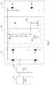
- FIG. 1is a schematic circuit diagram of the first embodiment of the LED lamp circuit according to the present invention.
- FIG. 2is a schematic diagram of the change in resistance of a negative temperature coefficient thermistor with temperature in the first embodiment of the present invention.
- FIG. 3is a schematic circuit diagram of the second embodiment of the LED lamp circuit according to the present invention.
- FIG. 4is a schematic diagram of the change in resistance of a positive temperature coefficient thermistor with temperature in the second embodiment of the present invention.
- FIG. 1shows the first embodiment of the present invention, which comprises an electronic ballast 11 for driving an LED lamp, four lamp pins 12 connected to the electronic ballast 11 , a high-frequency rectifier circuit 13 and LED luminous component circuit 17 connected to the four lamp pins 12 , and an output control circuit 14 coupled between the high-frequency rectifier circuit 13 and the LED luminous component circuit 17 .
- the high-frequency rectifier circuit 13is a full-wave bridge rectifier circuit, comprising four rectifier diodes D 1 , D 2 , D 3 , and D 4 .
- the high-frequency rectifier circuit 13is configured to regulate the voltage of the LED luminous component circuit 17 , convert the high-frequency alternating current output from the electronic ballast 11 into a direct current, and output the regulated voltage and current required by both ends V+ and V ⁇ to drive the LED luminous component circuit 17 .
- the output control circuit 14comprises a voltage regulator circuit 15 connected in parallel with the high-frequency rectifier circuit 13 , and a control switch circuit 16 coupled between the voltage regulator circuit 15 and the LED luminous component circuit 17 .
- the voltage regulator circuit 15comprises a thermosensitive device 18 and a voltage divider 19 connected in series.
- the thermosensitive device 18can regulate the control voltage at both ends of the control switch circuit 16 .
- the control switch circuit 16disconnects when the control voltage is less than the threshold voltage of the control switch circuit 16 .
- the thermosensitive device 18may comprise at least one negative temperature coefficient thermistor or at least one positive temperature coefficient thermistor.
- the voltage divider 19comprises a voltage dividing resistor, a voltage regulator tube, or other voltage-regulating device that can perform voltage division.
- the thermosensitive device 18comprises four negative temperature coefficient thermistors NTC 1 , NTC 2 , NTC 3 , and NTC 4 (hereinafter NTC) respectively coupled to the four lamp pins 12 of the LED lamp.
- the voltage divider 19comprises a voltage dividing resistor R.
- the four negative temperature coefficient thermistors NTCare connected in parallel to form the thermosensitive device 18 .
- One end of the thermosensitive device 18is connected in series with the voltage divider 19 , while the other end is connected to the DC output voltage V ⁇ end of the high-frequency rectifier circuit 13 .
- the other end of the voltage divider 19is connected to the DC output voltage V+ end of the high-frequency rectifier circuit 13 .
- the control switch circuit 16comprises a field-effect transistor switching tube, which is connected in parallel with the thermosensitive device 18 (negative temperature coefficient thermistors NTC).
- the field-effect transistor switching tubecomprises a gate G, a source S, and a drain D.
- the source S of the field-effect transistor switching tubeis connected to one end of the thermosensitive device 18
- the gate G of the field-effect transistor switching tubeis connected to the other end of the thermosensitive device 18 , or in other words, connected between the thermosensitive device 18 and the voltage divider 19 .
- the drain D of the field-effect transistor switching tube Qis connected to the LED luminous component circuit 17 .
- the number of negative temperature coefficient thermistors NTC connected in paralleldepends on the number of LED lamp pins.
- the number of LED lamp pinsis the same as the number of negative temperature coefficient thermistors NTC connected in parallel.
- the LED lamphas four lamp pins 12 .
- the LED lamp circuitcomprises four negative temperature coefficient thermistors NTC connected in parallel and respectively coupled to the four lamp pins 12 .
- the LED lampmay also comprise two lamp pins.
- the LED lamp circuitcomprises two negative temperature coefficient thermistors connected in parallel and respectively coupled to the two lamp pins.
- the LED luminous component circuit 17comprises a light-emitting diode component, which comprises a plurality of light-emitting diodes LED 1 to LEDN connected in series.
- the LED luminous component circuit 17further comprises a filter capacitor C connected in parallel with the light-emitting diode component.
- One end (the anode) of the filter capacitor Cis connected to one end of the voltage divider 19 , and the two are then connected to the V+ output end of the high-frequency rectifier circuit 3 .
- the other end (the cathode) of the filter capacitor Cis connected to the drain D of the field-effect transistor switching tube Q.
- the anode of the light-emitting diode componentis connected to the anode of the filter capacitor C.
- the cathode of the light-emitting diode componentis connected to the cathode of the filter capacitor C, and the two are then connected to the drain D of the field-effect transistor switching tube Q.
- the filter capacitor Ccan reduce the ripple current of the light-emitting diodes LED 1 to LEDN, so as to provider a better light-emitting effect.
- thermosensitive device 18decreases as the temperature rises, whereas the resistance value increases as the temperature decreases.
- the control voltage V GSdecreases accordingly.
- the control voltage V GSis less than the turn-on threshold voltage of the field-effect transistor switching tube, the field-effect transistor switching tube is turned off, and the entire circuit is disconnected. No current flows through the entire circuit, thereby eliminating the arc and protecting the LED lamp.
- FIG. 3shows an LED lamp circuit driven by an electronic ballast according to another embodiment of the present invention, which also comprises an electronic ballast 21 for driving an LED lamp, four lamp pins 22 connected to the electronic ballast 21 , a high-frequency rectifier circuit 23 and an LED luminous component circuit 27 connected to the four lamp pins 22 , and an output control circuit 24 coupled between the high-frequency rectifier circuit 23 and the LED luminous component circuit 27 .
- the output control circuit 24comprises a voltage regulator circuit 25 and a control switch circuit 26 .
- the voltage regulator circuit 25 and the high-frequency rectifier circuit 23are connected in parallel.
- the voltage regulator circuit 25comprises a thermosensitive device 28 and a voltage divider 29 connected in series.
- the thermosensitive device 28may comprise at least one positive temperature coefficient thermistor.
- the voltage divider 29comprises a voltage dividing resistor, a voltage regulator tube, or other voltage-regulating device that can perform voltage division.
- the thermosensitive device 28comprises four positive temperature coefficient thermistors PTC 1 , PTC 2 , PTC 3 , and PTC 4 (hereinafter PTC) connected in series.
- the four positive temperature coefficient thermistors PTCare connected in series to form the thermosensitive device 28 .
- One end of the thermosensitive device 28is connected to the voltage divider 29 , and the other end is connected to the DC output voltage V+ end of the high-frequency rectifier circuit 23 .
- the other end of the voltage divider 29is connected to the V ⁇ output end of the high-frequency rectifier circuit 23 .
- the control switch circuit 26comprises a field-effect transistor switching tube, which is connected in series with the thermosensitive device 28 (which comprises the four positive temperature coefficient thermistors PTC that are connected in series).
- the field-effect transistor switching tubecomprises a gate G, a source S, and a drain D.
- the gate G of the field-effect transistor switching tubeis connected to one end of the voltage divider 29 , or in other words, connected between the voltage divider 29 and the thermosensitive device 28 .
- the source S of the field-effect transistor switching tubeis connected to the other end of the voltage divider 29 .
- the drain D of the field-effect transistor switching tubeis connected to the LED luminous component circuit 7 .
- the number of positive temperature coefficient thermistors PTC connected in seriesdepends on the number of LED lamp pins.
- the number of LED lamp pinsis the same as the number of positive temperature coefficient thermistors PTC connected in series.
- the LED lamphas four lamp pins 22 .
- the LED lamp circuitcomprises four positive temperature coefficient thermistors connected in series PTC and respectively coupled to the four lamp pins 22 .
- the LED lampmay also comprise two lamp pins.
- the LED lamp circuitcomprises two positive temperature coefficient thermistors connected in series and respectively coupled to the two lamp pins.
- thermosensitive device 28increases as the temperature rises, and the resistance value decreases as the temperature decreases.
- thermosensitive device 28which comprises the positive temperature coefficient thermistors PTC connected in series
- the control voltage V GS of the field-effect transistor switching tube Qis sufficient.
- V GSV LED/ (1+(R PTC1 + . . . +R PTC4 )/R) of the control voltage of the field-effect transistor switching tube Q
- the control voltage V GSdecreases accordingly.
- the control voltage V GSis less than the turn-on threshold voltage of the field-effect transistor switching tube Q
- the field-effect transistor switching tube Qis turned off, and the entire circuit is disconnected. No current flows through the entire circuit, thereby eliminating the arc and protecting the LED lamp.
Landscapes
- Circuit Arrangement For Electric Light Sources In General (AREA)
Abstract
Description
VGS=VLED/(1+R/(RNTC1// . . . //RNTCN))
VGS=VLED/(1+(RPTC1+ . . . +RPTC4)/R)
Claims (11)
Applications Claiming Priority (3)
| Application Number | Priority Date | Filing Date | Title |
|---|---|---|---|
| CN201710378151.4 | 2017-05-25 | ||
| CN201710378151.4ACN108934103B (en) | 2017-05-25 | 2017-05-25 | Circuit of LED lamp |
| PCT/US2018/033621WO2018217609A2 (en) | 2017-05-25 | 2018-05-21 | Led lamp circuit |
Publications (2)
| Publication Number | Publication Date |
|---|---|
| US20200137854A1 US20200137854A1 (en) | 2020-04-30 |
| US11317496B2true US11317496B2 (en) | 2022-04-26 |
Family
ID=64395853
Family Applications (1)
| Application Number | Title | Priority Date | Filing Date |
|---|---|---|---|
| US16/495,960ActiveUS11317496B2 (en) | 2017-05-25 | 2018-05-21 | LED lamp circuit |
Country Status (4)
| Country | Link |
|---|---|
| US (1) | US11317496B2 (en) |
| CN (1) | CN108934103B (en) |
| CA (1) | CA3063467A1 (en) |
| WO (1) | WO2018217609A2 (en) |
Families Citing this family (2)
| Publication number | Priority date | Publication date | Assignee | Title |
|---|---|---|---|---|
| EP3820253A1 (en)* | 2019-11-11 | 2021-05-12 | GaN Power Technology Co., Ltd. | Led driving structure |
| JP7303983B2 (en)* | 2019-11-27 | 2023-07-06 | 東芝ライテック株式会社 | Vehicle lighting device and vehicle lamp |
Citations (29)
| Publication number | Priority date | Publication date | Assignee | Title |
|---|---|---|---|---|
| US3187576A (en)* | 1960-05-18 | 1965-06-08 | Frontier Dev Inc | Electronic thermometer |
| US3623367A (en)* | 1969-12-23 | 1971-11-30 | Westinghouse Electric Corp | Apparatus for measuring the average temperature of a gas stream |
| US3777234A (en)* | 1971-09-13 | 1973-12-04 | Agfa Gevaert Ag | Circuit arrangement for regulating the speed of a dc motor |
| US4301407A (en)* | 1978-10-26 | 1981-11-17 | Siemens Aktiengesellschaft | Hand held testing device for indicating an electric test voltage |
| US5354965A (en)* | 1990-08-21 | 1994-10-11 | Gensonic, Inc. | Window cleaning fluid heating system having timer-controlled heater and differential input circuit |
| US6111739A (en) | 1999-08-11 | 2000-08-29 | Leotek Electronics Corporation | LED power supply with temperature compensation |
| CN2643538Y (en)* | 2003-08-28 | 2004-09-22 | 上海开通数控有限公司 | Soft starter for whole digit AC servo drive system |
| US20070040696A1 (en)* | 2005-08-18 | 2007-02-22 | Honeywell International Inc. | Aerospace light-emitting diode (LED)-based lights life and operation monitor compensator |
| US20080130288A1 (en)* | 2003-09-12 | 2008-06-05 | Anthony Catalano | Light Emitting Diode Replacement Lamp |
| US20090100924A1 (en)* | 2007-10-23 | 2009-04-23 | Therm-O-Disc, Incorporated | Fluid Flow Rate Sensor And Method Of Operation |
| US20100039794A1 (en) | 2008-08-15 | 2010-02-18 | Lumination Llc. | Traffic led lamp with internal circuit backup system |
| US20110298374A1 (en)* | 2011-06-07 | 2011-12-08 | Switch Bulb Company, Inc. | Thermal protection circuit for an led bulb |
| US20110304201A1 (en)* | 2009-07-08 | 2011-12-15 | Haixiang Wang | Regulating Device of General Automobile Performance |
| US20120038289A1 (en) | 2010-08-11 | 2012-02-16 | Yong Keun Jee | Led lamp and driving circuit for the same |
| US8330381B2 (en) | 2009-05-14 | 2012-12-11 | Ilumisys, Inc. | Electronic circuit for DC conversion of fluorescent lighting ballast |
| US20130141004A1 (en)* | 2011-12-01 | 2013-06-06 | RAB Lighting Inc. | Led driver protection circuit |
| CN203840609U (en) | 2014-05-05 | 2014-09-17 | 长治市华杰光电科技有限公司 | LED circuit having overheating protection function |
| US8896235B1 (en)* | 2010-11-17 | 2014-11-25 | Soraa, Inc. | High temperature LED system using an AC power source |
| CN104545479A (en) | 2013-10-23 | 2015-04-29 | 吴长江 | Heater for water dispensers and water dispenser |
| WO2015066566A1 (en) | 2013-10-31 | 2015-05-07 | Innosys, Inc. | Fluorescent lamp replacement led protection |
| US20150208470A1 (en) | 2014-01-17 | 2015-07-23 | Shang-Kuei Tsai | Led light with triac-ballasted |
| JP2015215214A (en)* | 2014-05-09 | 2015-12-03 | Koa株式会社 | Temperature history storage device |
| US20150382420A1 (en)* | 2013-02-18 | 2015-12-31 | Citizen Holdings Co., Ltd. | Led drive circuit |
| US9243757B2 (en) | 2013-05-02 | 2016-01-26 | Lunera Lighting, Inc. | Retrofit LED lighting system for replacement of fluorescent lamp |
| US20160172898A1 (en)* | 2014-12-15 | 2016-06-16 | Commissariat à l'énergie atomique et aux énergies alternatives | Circuit for comparing a voltage with a threshold |
| US20160226393A1 (en)* | 2015-01-29 | 2016-08-04 | Technical Consumer Products, Inc. | Light emitting diode (led) driver having direct replacement capabilities |
| US20170184840A1 (en)* | 2014-04-01 | 2017-06-29 | Agiltron, Inc. | Microelectromechanical displacement structure and method for controlling displacement |
| US20180183315A1 (en)* | 2016-12-28 | 2018-06-28 | Dongguan City Minleon Electronics Co., Ltd. | Drive Circuit for Transmitting Data Signals on Power Wire |
| US20180301073A1 (en)* | 2017-04-14 | 2018-10-18 | Schneider Electric Industries Sas | Bistable display and driving method thereof |
Family Cites Families (5)
| Publication number | Priority date | Publication date | Assignee | Title |
|---|---|---|---|---|
| KR200432142Y1 (en)* | 2006-09-19 | 2006-12-01 | 금호전기주식회사 | LED current control circuit using PTC element |
| CN202048996U (en)* | 2011-04-28 | 2011-11-23 | 海洋王照明科技股份有限公司 | Temperature monitoring circuit and led lamp |
| CN103001177B (en)* | 2011-09-19 | 2016-03-30 | 海洋王(东莞)照明科技有限公司 | A kind of LED lamp and overheating protection circuit thereof |
| CN103391660A (en)* | 2012-05-09 | 2013-11-13 | 海洋王(东莞)照明科技有限公司 | LED lamp over-temperature protection circuit and LED lamp |
| CN204090219U (en)* | 2014-07-17 | 2015-01-07 | 张秀红 | A kind of overheating protection circuit of LED |
- 2017
- 2017-05-25CNCN201710378151.4Apatent/CN108934103B/ennot_activeExpired - Fee Related
- 2018
- 2018-05-21WOPCT/US2018/033621patent/WO2018217609A2/ennot_activeCeased
- 2018-05-21CACA3063467Apatent/CA3063467A1/ennot_activeAbandoned
- 2018-05-21USUS16/495,960patent/US11317496B2/enactiveActive
Patent Citations (29)
| Publication number | Priority date | Publication date | Assignee | Title |
|---|---|---|---|---|
| US3187576A (en)* | 1960-05-18 | 1965-06-08 | Frontier Dev Inc | Electronic thermometer |
| US3623367A (en)* | 1969-12-23 | 1971-11-30 | Westinghouse Electric Corp | Apparatus for measuring the average temperature of a gas stream |
| US3777234A (en)* | 1971-09-13 | 1973-12-04 | Agfa Gevaert Ag | Circuit arrangement for regulating the speed of a dc motor |
| US4301407A (en)* | 1978-10-26 | 1981-11-17 | Siemens Aktiengesellschaft | Hand held testing device for indicating an electric test voltage |
| US5354965A (en)* | 1990-08-21 | 1994-10-11 | Gensonic, Inc. | Window cleaning fluid heating system having timer-controlled heater and differential input circuit |
| US6111739A (en) | 1999-08-11 | 2000-08-29 | Leotek Electronics Corporation | LED power supply with temperature compensation |
| CN2643538Y (en)* | 2003-08-28 | 2004-09-22 | 上海开通数控有限公司 | Soft starter for whole digit AC servo drive system |
| US20080130288A1 (en)* | 2003-09-12 | 2008-06-05 | Anthony Catalano | Light Emitting Diode Replacement Lamp |
| US20070040696A1 (en)* | 2005-08-18 | 2007-02-22 | Honeywell International Inc. | Aerospace light-emitting diode (LED)-based lights life and operation monitor compensator |
| US20090100924A1 (en)* | 2007-10-23 | 2009-04-23 | Therm-O-Disc, Incorporated | Fluid Flow Rate Sensor And Method Of Operation |
| US20100039794A1 (en) | 2008-08-15 | 2010-02-18 | Lumination Llc. | Traffic led lamp with internal circuit backup system |
| US8330381B2 (en) | 2009-05-14 | 2012-12-11 | Ilumisys, Inc. | Electronic circuit for DC conversion of fluorescent lighting ballast |
| US20110304201A1 (en)* | 2009-07-08 | 2011-12-15 | Haixiang Wang | Regulating Device of General Automobile Performance |
| US20120038289A1 (en) | 2010-08-11 | 2012-02-16 | Yong Keun Jee | Led lamp and driving circuit for the same |
| US8896235B1 (en)* | 2010-11-17 | 2014-11-25 | Soraa, Inc. | High temperature LED system using an AC power source |
| US20110298374A1 (en)* | 2011-06-07 | 2011-12-08 | Switch Bulb Company, Inc. | Thermal protection circuit for an led bulb |
| US20130141004A1 (en)* | 2011-12-01 | 2013-06-06 | RAB Lighting Inc. | Led driver protection circuit |
| US20150382420A1 (en)* | 2013-02-18 | 2015-12-31 | Citizen Holdings Co., Ltd. | Led drive circuit |
| US9243757B2 (en) | 2013-05-02 | 2016-01-26 | Lunera Lighting, Inc. | Retrofit LED lighting system for replacement of fluorescent lamp |
| CN104545479A (en) | 2013-10-23 | 2015-04-29 | 吴长江 | Heater for water dispensers and water dispenser |
| WO2015066566A1 (en) | 2013-10-31 | 2015-05-07 | Innosys, Inc. | Fluorescent lamp replacement led protection |
| US20150208470A1 (en) | 2014-01-17 | 2015-07-23 | Shang-Kuei Tsai | Led light with triac-ballasted |
| US20170184840A1 (en)* | 2014-04-01 | 2017-06-29 | Agiltron, Inc. | Microelectromechanical displacement structure and method for controlling displacement |
| CN203840609U (en) | 2014-05-05 | 2014-09-17 | 长治市华杰光电科技有限公司 | LED circuit having overheating protection function |
| JP2015215214A (en)* | 2014-05-09 | 2015-12-03 | Koa株式会社 | Temperature history storage device |
| US20160172898A1 (en)* | 2014-12-15 | 2016-06-16 | Commissariat à l'énergie atomique et aux énergies alternatives | Circuit for comparing a voltage with a threshold |
| US20160226393A1 (en)* | 2015-01-29 | 2016-08-04 | Technical Consumer Products, Inc. | Light emitting diode (led) driver having direct replacement capabilities |
| US20180183315A1 (en)* | 2016-12-28 | 2018-06-28 | Dongguan City Minleon Electronics Co., Ltd. | Drive Circuit for Transmitting Data Signals on Power Wire |
| US20180301073A1 (en)* | 2017-04-14 | 2018-10-18 | Schneider Electric Industries Sas | Bistable display and driving method thereof |
Non-Patent Citations (2)
| Title |
|---|
| Chinese Office Action dated Aug. 19, 2019 which was issued in connection with CN201710378151.4 which was filed on May 25, 2017. |
| International Search Report and Written Opinion dated Nov. 15, 2018 which was issued in connection with PCT/US18/33621 which was filed on May 21, 2018. |
Also Published As
| Publication number | Publication date |
|---|---|
| CN108934103B (en) | 2021-07-30 |
| US20200137854A1 (en) | 2020-04-30 |
| CN108934103A (en) | 2018-12-04 |
| WO2018217609A2 (en) | 2018-11-29 |
| CA3063467A1 (en) | 2018-11-29 |
| WO2018217609A3 (en) | 2019-01-03 |
Similar Documents
| Publication | Publication Date | Title |
|---|---|---|
| US9860958B2 (en) | Dimming drive circuit of alternating current directly-driven LED module | |
| CN102387638B (en) | LED (Light-emitting Diode) lamp with temperature-control protective circuit | |
| CN108966430B (en) | A linear drive circuit for LED lighting | |
| US20130127367A1 (en) | Lighting device and illumination apparatus | |
| CN102307411A (en) | Light-emitting diode (LED) lamp control circuit having key element overvoltage protection function | |
| US11051378B2 (en) | Eliminating flicker and open load protection for driver compatible with NAFTA dim ECG | |
| CN105027682A (en) | Control circuit for light emitting diode lighting device | |
| US11317496B2 (en) | LED lamp circuit | |
| CN103188845A (en) | LED lighting device directly driven by alternating current | |
| KR101365307B1 (en) | Switching power supply circuit for LED lighting equipment | |
| CN111212497A (en) | Driving circuit | |
| KR20110051691A (en) | Constant current power supply such as LED lighting | |
| JP5724516B2 (en) | LED lighting device | |
| CN113301690B (en) | Lighting lamp driving chip and driving circuit | |
| US10959309B2 (en) | LED lamp protection circuit | |
| KR20140104196A (en) | Power supply circuit for light emitting diode lighting | |
| KR20110004892U (en) | LED element constant current driving device | |
| KR101784857B1 (en) | Driving Device of LED Lamp Compatable with a circle, FPL and Fluorescent Lamp Stabilizer | |
| CN202050573U (en) | LED (light-emitting diode) lamp control circuit with overvoltage protection function for key components | |
| KR101091046B1 (en) | LED lighting circuit with stabilizer for fluorescent lamp | |
| CN108712807A (en) | The driving circuit of light emitting diode | |
| KR101728415B1 (en) | Ac direct-type led lighting circuit with protection | |
| CN208523031U (en) | The driving circuit of light emitting diode | |
| CN201976304U (en) | Multichannel light emitting diode driving system | |
| KR100919420B1 (en) | Led lamp with smoothing circuit |
Legal Events
| Date | Code | Title | Description |
|---|---|---|---|
| AS | Assignment | Owner name:GE LIGHTING SOLUTIONS, LLC, OHIO Free format text:ASSIGNMENT OF ASSIGNORS INTEREST;ASSIGNORS:MAO, ZHU;LONG, QI;FANG, MIN;AND OTHERS;REEL/FRAME:050442/0372 Effective date:20170921 Owner name:CURRENT LIGHTING SOLUTIONS, LLC, OHIO Free format text:CHANGE OF NAME;ASSIGNOR:GE LIGHTING SOLUTIONS, LLC;REEL/FRAME:050455/0972 Effective date:20190401 | |
| FEPP | Fee payment procedure | Free format text:ENTITY STATUS SET TO UNDISCOUNTED (ORIGINAL EVENT CODE: BIG.); ENTITY STATUS OF PATENT OWNER: LARGE ENTITY | |
| STPP | Information on status: patent application and granting procedure in general | Free format text:NON FINAL ACTION MAILED | |
| STPP | Information on status: patent application and granting procedure in general | Free format text:RESPONSE AFTER FINAL ACTION FORWARDED TO EXAMINER | |
| STPP | Information on status: patent application and granting procedure in general | Free format text:DOCKETED NEW CASE - READY FOR EXAMINATION | |
| STPP | Information on status: patent application and granting procedure in general | Free format text:NON FINAL ACTION MAILED | |
| STPP | Information on status: patent application and granting procedure in general | Free format text:RESPONSE TO NON-FINAL OFFICE ACTION ENTERED AND FORWARDED TO EXAMINER | |
| STPP | Information on status: patent application and granting procedure in general | Free format text:FINAL REJECTION MAILED | |
| STPP | Information on status: patent application and granting procedure in general | Free format text:RESPONSE AFTER FINAL ACTION FORWARDED TO EXAMINER | |
| STPP | Information on status: patent application and granting procedure in general | Free format text:NOTICE OF ALLOWANCE MAILED -- APPLICATION RECEIVED IN OFFICE OF PUBLICATIONS | |
| AS | Assignment | Owner name:ALLY BANK, AS COLLATERAL AGENT, NEW YORK Free format text:SECURITY AGREEMENT;ASSIGNORS:HUBBELL LIGHTING, INC.;LITECONTROL CORPORATION;CURRENT LIGHTING SOLUTIONS, LLC;AND OTHERS;REEL/FRAME:058982/0844 Effective date:20220201 | |
| AS | Assignment | Owner name:ATLANTIC PARK STRATEGIC CAPITAL FUND, L.P., AS COLLATERAL AGENT, NEW YORK Free format text:SECURITY INTEREST;ASSIGNORS:HUBBELL LIGHTING, INC.;LITECONTROL CORPORATION;CURRENT LIGHTING SOLUTIONS, LLC;AND OTHERS;REEL/FRAME:059034/0469 Effective date:20220201 | |
| STPP | Information on status: patent application and granting procedure in general | Free format text:PUBLICATIONS -- ISSUE FEE PAYMENT VERIFIED | |
| STCF | Information on status: patent grant | Free format text:PATENTED CASE | |
| AS | Assignment | Owner name:ALLY BANK, AS COLLATERAL AGENT, NEW YORK Free format text:CORRECTIVE ASSIGNMENT TO CORRECT THE PATENT NUMBER 10841994 TO PATENT NUMBER 11570872 PREVIOUSLY RECORDED ON REEL 058982 FRAME 0844. ASSIGNOR(S) HEREBY CONFIRMS THE SECURITY AGREEMENT;ASSIGNORS:HUBBELL LIGHTING, INC.;LITECONTROL CORPORATION;CURRENT LIGHTING SOLUTIONS, LLC;AND OTHERS;REEL/FRAME:066355/0455 Effective date:20220201 | |
| AS | Assignment | Owner name:ATLANTIC PARK STRATEGIC CAPITAL FUND, L.P., AS COLLATERAL AGENT, NEW YORK Free format text:CORRECTIVE ASSIGNMENT TO CORRECT THE PATENT NUMBER PREVIOUSLY RECORDED AT REEL: 059034 FRAME: 0469. ASSIGNOR(S) HEREBY CONFIRMS THE SECURITY INTEREST;ASSIGNORS:HUBBELL LIGHTING, INC.;LITECONTROL CORPORATION;CURRENT LIGHTING SOLUTIONS, LLC;AND OTHERS;REEL/FRAME:066372/0590 Effective date:20220201 | |
| MAFP | Maintenance fee payment | Free format text:PAYMENT OF MAINTENANCE FEE, 4TH YEAR, LARGE ENTITY (ORIGINAL EVENT CODE: M1551); ENTITY STATUS OF PATENT OWNER: LARGE ENTITY Year of fee payment:4 |