US11313673B2 - Methods of making a component with an integral strain indicator - Google Patents
Methods of making a component with an integral strain indicatorDownload PDFInfo
- Publication number
- US11313673B2 US11313673B2US15/413,864US201715413864AUS11313673B2US 11313673 B2US11313673 B2US 11313673B2US 201715413864 AUS201715413864 AUS 201715413864AUS 11313673 B2US11313673 B2US 11313673B2
- Authority
- US
- United States
- Prior art keywords
- component
- fiducial markers
- fiducial
- markers
- marker
- Prior art date
- Legal status (The legal status is an assumption and is not a legal conclusion. Google has not performed a legal analysis and makes no representation as to the accuracy of the status listed.)
- Active, expires
Links
Images


Classifications
- F—MECHANICAL ENGINEERING; LIGHTING; HEATING; WEAPONS; BLASTING
- F01—MACHINES OR ENGINES IN GENERAL; ENGINE PLANTS IN GENERAL; STEAM ENGINES
- F01D—NON-POSITIVE DISPLACEMENT MACHINES OR ENGINES, e.g. STEAM TURBINES
- F01D17/00—Regulating or controlling by varying flow
- F01D17/02—Arrangement of sensing elements
- F01D17/04—Arrangement of sensing elements responsive to load
- G—PHYSICS
- G01—MEASURING; TESTING
- G01B—MEASURING LENGTH, THICKNESS OR SIMILAR LINEAR DIMENSIONS; MEASURING ANGLES; MEASURING AREAS; MEASURING IRREGULARITIES OF SURFACES OR CONTOURS
- G01B11/00—Measuring arrangements characterised by the use of optical techniques
- G01B11/002—Measuring arrangements characterised by the use of optical techniques for measuring two or more coordinates
- B—PERFORMING OPERATIONS; TRANSPORTING
- B22—CASTING; POWDER METALLURGY
- B22F—WORKING METALLIC POWDER; MANUFACTURE OF ARTICLES FROM METALLIC POWDER; MAKING METALLIC POWDER; APPARATUS OR DEVICES SPECIALLY ADAPTED FOR METALLIC POWDER
- B22F10/00—Additive manufacturing of workpieces or articles from metallic powder
- B22F10/20—Direct sintering or melting
- B22F10/25—Direct deposition of metal particles, e.g. direct metal deposition [DMD] or laser engineered net shaping [LENS]
- B—PERFORMING OPERATIONS; TRANSPORTING
- B22—CASTING; POWDER METALLURGY
- B22F—WORKING METALLIC POWDER; MANUFACTURE OF ARTICLES FROM METALLIC POWDER; MAKING METALLIC POWDER; APPARATUS OR DEVICES SPECIALLY ADAPTED FOR METALLIC POWDER
- B22F10/00—Additive manufacturing of workpieces or articles from metallic powder
- B22F10/80—Data acquisition or data processing
- B—PERFORMING OPERATIONS; TRANSPORTING
- B22—CASTING; POWDER METALLURGY
- B22F—WORKING METALLIC POWDER; MANUFACTURE OF ARTICLES FROM METALLIC POWDER; MAKING METALLIC POWDER; APPARATUS OR DEVICES SPECIALLY ADAPTED FOR METALLIC POWDER
- B22F7/00—Manufacture of composite layers, workpieces, or articles, comprising metallic powder, by sintering the powder, with or without compacting wherein at least one part is obtained by sintering or compression
- B22F7/02—Manufacture of composite layers, workpieces, or articles, comprising metallic powder, by sintering the powder, with or without compacting wherein at least one part is obtained by sintering or compression of composite layers
- B—PERFORMING OPERATIONS; TRANSPORTING
- B33—ADDITIVE MANUFACTURING TECHNOLOGY
- B33Y—ADDITIVE MANUFACTURING, i.e. MANUFACTURING OF THREE-DIMENSIONAL [3-D] OBJECTS BY ADDITIVE DEPOSITION, ADDITIVE AGGLOMERATION OR ADDITIVE LAYERING, e.g. BY 3-D PRINTING, STEREOLITHOGRAPHY OR SELECTIVE LASER SINTERING
- B33Y10/00—Processes of additive manufacturing
- B—PERFORMING OPERATIONS; TRANSPORTING
- B33—ADDITIVE MANUFACTURING TECHNOLOGY
- B33Y—ADDITIVE MANUFACTURING, i.e. MANUFACTURING OF THREE-DIMENSIONAL [3-D] OBJECTS BY ADDITIVE DEPOSITION, ADDITIVE AGGLOMERATION OR ADDITIVE LAYERING, e.g. BY 3-D PRINTING, STEREOLITHOGRAPHY OR SELECTIVE LASER SINTERING
- B33Y80/00—Products made by additive manufacturing
- F—MECHANICAL ENGINEERING; LIGHTING; HEATING; WEAPONS; BLASTING
- F01—MACHINES OR ENGINES IN GENERAL; ENGINE PLANTS IN GENERAL; STEAM ENGINES
- F01D—NON-POSITIVE DISPLACEMENT MACHINES OR ENGINES, e.g. STEAM TURBINES
- F01D21/00—Shutting-down of machines or engines, e.g. in emergency; Regulating, controlling, or safety means not otherwise provided for
- F01D21/003—Arrangements for testing or measuring
- G—PHYSICS
- G01—MEASURING; TESTING
- G01B—MEASURING LENGTH, THICKNESS OR SIMILAR LINEAR DIMENSIONS; MEASURING ANGLES; MEASURING AREAS; MEASURING IRREGULARITIES OF SURFACES OR CONTOURS
- G01B11/00—Measuring arrangements characterised by the use of optical techniques
- G01B11/16—Measuring arrangements characterised by the use of optical techniques for measuring the deformation in a solid, e.g. optical strain gauge
- G—PHYSICS
- G01—MEASURING; TESTING
- G01B—MEASURING LENGTH, THICKNESS OR SIMILAR LINEAR DIMENSIONS; MEASURING ANGLES; MEASURING AREAS; MEASURING IRREGULARITIES OF SURFACES OR CONTOURS
- G01B11/00—Measuring arrangements characterised by the use of optical techniques
- G01B11/24—Measuring arrangements characterised by the use of optical techniques for measuring contours or curvatures
- G—PHYSICS
- G01—MEASURING; TESTING
- G01B—MEASURING LENGTH, THICKNESS OR SIMILAR LINEAR DIMENSIONS; MEASURING ANGLES; MEASURING AREAS; MEASURING IRREGULARITIES OF SURFACES OR CONTOURS
- G01B21/00—Measuring arrangements or details thereof, where the measuring technique is not covered by the other groups of this subclass, unspecified or not relevant
- G01B21/02—Measuring arrangements or details thereof, where the measuring technique is not covered by the other groups of this subclass, unspecified or not relevant for measuring length, width, or thickness
- G01B21/04—Measuring arrangements or details thereof, where the measuring technique is not covered by the other groups of this subclass, unspecified or not relevant for measuring length, width, or thickness by measuring coordinates of points
- G01B21/047—Accessories, e.g. for positioning, for tool-setting, for measuring probes
- G—PHYSICS
- G01—MEASURING; TESTING
- G01B—MEASURING LENGTH, THICKNESS OR SIMILAR LINEAR DIMENSIONS; MEASURING ANGLES; MEASURING AREAS; MEASURING IRREGULARITIES OF SURFACES OR CONTOURS
- G01B21/00—Measuring arrangements or details thereof, where the measuring technique is not covered by the other groups of this subclass, unspecified or not relevant
- G01B21/32—Measuring arrangements or details thereof, where the measuring technique is not covered by the other groups of this subclass, unspecified or not relevant for measuring the deformation in a solid
- B—PERFORMING OPERATIONS; TRANSPORTING
- B22—CASTING; POWDER METALLURGY
- B22F—WORKING METALLIC POWDER; MANUFACTURE OF ARTICLES FROM METALLIC POWDER; MAKING METALLIC POWDER; APPARATUS OR DEVICES SPECIALLY ADAPTED FOR METALLIC POWDER
- B22F10/00—Additive manufacturing of workpieces or articles from metallic powder
- B22F10/20—Direct sintering or melting
- B22F10/28—Powder bed fusion, e.g. selective laser melting [SLM] or electron beam melting [EBM]
- Y—GENERAL TAGGING OF NEW TECHNOLOGICAL DEVELOPMENTS; GENERAL TAGGING OF CROSS-SECTIONAL TECHNOLOGIES SPANNING OVER SEVERAL SECTIONS OF THE IPC; TECHNICAL SUBJECTS COVERED BY FORMER USPC CROSS-REFERENCE ART COLLECTIONS [XRACs] AND DIGESTS
- Y02—TECHNOLOGIES OR APPLICATIONS FOR MITIGATION OR ADAPTATION AGAINST CLIMATE CHANGE
- Y02P—CLIMATE CHANGE MITIGATION TECHNOLOGIES IN THE PRODUCTION OR PROCESSING OF GOODS
- Y02P10/00—Technologies related to metal processing
- Y02P10/25—Process efficiency
Definitions
- the present disclosurerelates generally to methods for monitoring component strain, and methods for making a component with an integral strain indicator.
- apparatus componentsare subjected to numerous extreme conditions (e.g., high temperatures, high pressures, large stress loads, etc.). Over time, an apparatus's individual components may suffer creep and/or deformation that may reduce the component's usable life. Such concerns might apply, for instance, to some turbomachines.
- a conventional gas turbine systemincludes a compressor section, a combustor section, and at least one turbine section.
- the compressor sectionis configured to compress a working fluid (e.g., air) as the working fluid flows through the compressor section.
- the compressor sectionsupplies a high pressure compressed working fluid to the combustors where the high pressure working fluid is mixed with a fuel and burned in a combustion chamber to generate combustion gases having a high temperature and pressure.
- the combustion gasesflow along a hot gas path into the turbine section.
- the turbine sectionutilizes the combustion gases by extracting energy therefrom to produce work. For example, expansion of the combustion gases in the turbine section may rotate a shaft to power the compressor, an electrical generator, and other various loads.
- various components within the turbomachine and particularly components along the hot gas pathsuch as turbine blades within the turbine section of the turbomachine, may be subject to creep due to high temperatures and stresses.
- creepmay cause portions of or the entire blade to elongate so that the blade tips contact a stationary structure, for example a turbine casing, and potentially cause unwanted vibrations and/or reduced performance during operation.
- a method of making a component with an integral strain indicatorincludes forming the component, the component including an internal volume including a first material and an outer surface. The method further includes directly depositing a plurality of fiducial markers on a portion of the outer surface.
- the fiducial markersinclude a second material that is compatible with the first material and the portion of the outer surface includes an analysis region on the outer surface of the component.
- the analysis regiondefines a gage length, and each fiducial marker of the plurality of fiducial markers has a maximum diameter of between one-tenth and one-twentieth of the gage length.
- a method of monitoring a componentincludes an internal volume including a first material and an outer surface.
- the methodincludes initially directly measuring a plurality of fiducial markers on a portion of the outer surface of the component with a three-dimensional data acquisition device and creating a three-dimensional model of the component based on the initial direct measurement.
- the methodalso includes subjecting the component to at least one duty cycle, subsequently directly measuring the plurality of fiducial markers after the at least one duty cycle with the three-dimensional data acquisition device, and creating a three-dimensional model of the component based on the subsequent direct measurement.
- the methodfurther includes comparing the three-dimensional model based on the initial direct measurement to the three-dimensional model based on the subsequent direct measurement.
- the plurality of fiducial markersare directly deposited on the portion of the outer surface of the component and the fiducial markers comprise a second material compatible with the first material.
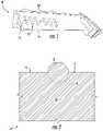
- FIG. 1is a perspective view of an exemplary component including a plurality of fiducial markers in accordance with embodiments of the present disclosure
- FIG. 2is a partial section view of the component of FIG. 1 including a fiducial marker formed thereon in accordance with embodiments of the present disclosure
- FIG. 3is a partial section view of the component of FIG. 1 including a fiducial marker formed thereon in accordance with additional embodiments of the present disclosure
- FIG. 4is a partial section view of the component of FIG. 1 including a fiducial marker formed thereon in accordance with further additional embodiments of the present disclosure
- FIG. 5is a perspective view of a system for monitoring component strain in accordance with embodiments of the present disclosure
- FIG. 6is a an overhead view of a plurality of fiducial markers in accordance with embodiments of the present disclosure
- FIG. 7is a an overhead view of a plurality of fiducial markers in accordance with embodiments of the present disclosure.
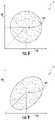
- FIG. 8is a section view of an exemplary fiducial marker at a first time in accordance with embodiments of the present disclosure
- FIG. 9is a section view of the fiducial marker of FIG. 8 at a second time in accordance with embodiments of the present disclosure.
- FIG. 10is a flow chart illustrating a method of making a component in accordance with embodiments of the present disclosure.
- FIG. 11is a flow chart illustrating a method for monitoring component deformation in accordance with one or more embodiments of the present disclosure.
- an exemplary component 10is illustrated with a plurality of fiducial markers 12 formed on the component's outer surface 14 .
- the component 10can be any of a variety of types of components used in a variety of different applications, such as components utilized in high temperature applications (e.g., components including nickel or cobalt based superalloys).
- the component 10may be an industrial gas turbine or steam turbine component such as a combustion component or hot gas path component.
- the component 10may be a turbine blade, compressor blade, vane, nozzle, shroud, rotor, transition piece or casing.
- the component 10may be any other component for a gas turbine, steam turbine or the like.
- the componentmay be a non-turbine component including, but not limited to, automotive components (e.g., cars, trucks, etc.), aerospace components (e.g., airplanes, helicopters, space shuttles, aluminum parts, etc.), locomotive or rail components (e.g., trains, train tracks, etc.), structural, infrastructure or civil engineering components (e.g., bridges, buildings, construction equipment, etc.), and/or power plant or chemical processing components (e.g., pipes used in high temperature applications).
- automotive componentse.g., cars, trucks, etc.
- aerospace componentse.g., airplanes, helicopters, space shuttles, aluminum parts, etc.
- locomotive or rail componentse.g., trains, train tracks, etc.
- structural, infrastructure or civil engineering componentse.g., bridges, buildings, construction equipment, etc.
- power plant or chemical processing componentse.g., pipes used in high temperature applications.
- the exemplary component 10has an outer surface 14 on which the fiducial markers 12 are positioned.
- the example component 10 shown in the illustrative embodiment of FIG. 1is a turbine component, more specifically, a turbine blade.
- the component 10can be various additional or alternative components, as described above.
- the fiducial markers 12are generally identifiable targets having a length L and width W (see FIG. 6 ) across the outer surface 14 .
- Certain fiducial marker 12 embodimentsmay further include a thickness relative to the outer surface 14 , thereby forming an elevated marker surface having a height H (see FIGS. 2-4 ) above the outer surface 14 .
- the exemplary component 10has an interior volume 15 which is formed from a first material.
- Various cooling passagesmay be defined in the interior volume 15 .
- suitable materials for the interior volume 15may include high performance nickel-based superalloys such as GTD- 111 , GTD- 141 , GTD- 444 , R 108 , INCONELTM 738 , or single crystal N 4 and N 5 .
- the turbine blade 10may be formed from other suitable metal or other materials.
- the fiducial markers 12may each be advantageously formed from a material, e.g., a second material, which is compatible with (and in some cases, identical to) the first material.
- a second materialmay be compatible with a first material when the addition of the second material does not create undesirable changes in the material properties or useable life of the component 10 .
- the fiducial markers 12may include a compatible second material with similar properties that may be life-limiting within the use environment of the component 10 . Examples of such properties are corrosion resistance and coefficient of thermal expansion.
- the component 10may be a hot gas path component of a gas turbine.
- the use environment of the component 10includes high temperatures to which the component 10 and any fiducial markers 12 formed thereon may be exposed, such that suitable compatible materials for the fiducial markers 12 would include materials with a coefficient of thermal expansion similar to the first material.
- the outer surface 14 of the component 10may be formed from the first material as well. In other embodiments, it is also possible for the outer surface 14 to include different materials, e.g., a thermal barrier layer material as discussed below.
- the second materialmay be a metal, a polymer, or a ceramic material, and may be applied by any suitable methods, such as additive methods, as will be described below.
- the fiducial markers 12are positioned on a portion 18 of the outer surface 14 of the component 10 .
- at least two discrete markerse.g., 12 a and 12 b
- these measurementscan help determine the amount of strain, strain rate, creep, fatigue, stress, etc. at that region of the component 10 .
- the at least two discrete markers 12 a and 12 bcan be disposed at a variety of distances and in a variety of locations depending on the specific component 10 so long as the distance D therebetween can be measured.
- the fiducial markers 12may have any suitable shapes, such as dots, lines, circles, rectangles or any other geometrical or non-geometrical shape, so long as they are consistently identifiable and may be used to measure the distance D therebetween.
- the fiducial markers 12may form a variety of different configurations and cross-sections such as by incorporating a variety of differently shaped, sized, and positioned fiducial markers 12 .
- each fiducial marker 12may include a matched or unique shape.
- each marker 12may define a circular shape, rectangular shape, or linear shape that is the same as (i.e., matched) or unique from another fiducial marker.
- the markers 12may be directly deposited on a portion of the outer surface 14 by various exemplary methods.
- the markers 12may be printed on the outer surface 14 of the component 10 .
- Suitable printing methodsinclude two-dimensional (2-D) or three-dimensional (3-D) printing, e.g., by screen printing, laser printing, direct ceramic inkjet printing, aerosol jet printing, or another suitable method.
- the markers 12may be directly deposited on the outer surface 14 of the component 10 by additive methods such as laser cladding, electro-spark deposition, spot welding, stick welding, powder-bed printing, soldering, brazing, or any other suitable additive method.
- a coating or thin film processing techniquemay be used to deposit the fiducial markers 12 on the portion of the outer surface.
- such techniquesinclude but are not limited to thermal spray, chemical deposition, physical vapor deposition, atomic layer deposition, and photoresist/chemical etching techniques.
- One exemplary welding methodmay include providing a welding rod of the second material and selectively welding the second material onto the outer surface 14 of component 10 to form the fiducial markers 12 .
- the component 10may also be formed by such additive manufacturing method, and the plurality of fiducial markers 12 may be directly deposited on a portion of the outer surface 14 of the component 10 during formation of the component 10 .
- the plurality of fiducial markers 12may be directly deposited by staining, painting, or adhering.
- the fiducial markers 12may be applied with and/or positioned in an optional bond layer 17 and/or thermal barrier layer 16 .
- the fiducial markers 12may be a portion of the thermal barrier layer 16 , e.g., the second material of the fiducial markers 12 may be the thermal barrier layer material.
- the outer surface 14is at least partially defined by thermal barrier layer 16 and the thermal barrier layer 16 includes the second material.
- Suitable thermal barrier layer materials for use in such embodimentsmay include, for example, yttria-stabilized zirconia (“YSZ”) or suitable ceramic-based compositions having low thermal conductivities.
- additional layerssuch as bond layer 17 may be provided between the thermal barrier layer 16 and the internal volume 15 of component 10 .
- the fiducial markers 12may be a portion of the bond layer 17 , e.g., the second material of the fiducial markers 12 may be the bond layer material.
- Suitable materials for use as bond layer 17may include, for example, an alloy of nickel, chromium, aluminum, and yttrium (“NiCrAlY”) an alloy of nickel, cobalt, chromium, aluminum, and yttrium (“NiCoCrAlY”) or other alloys sold under the tradenames GE 33 , GE 55 , Gel Aluminide, GT 21 , GT 29 , or GT 33 .
- the outer surface 14 on which the fiducial markers 12 are formedmay be, but is not necessarily, the outermost surface of the component 10 .
- outer surface 14may be the outermost surface of one of the layers, e.g., the substrate or internal volume 15 , the bond coat 17 (if present), or the thermal barrier layer 16 (if present). Further, in some embodiments, a thermally grown oxide may be included between the foregoing layers, e.g., between the bond coat 17 and the thermal barrier layer 16 .
- suitable methods of directly depositing the fiducial markers 12 on the outer surface 14 of the component 10include methods that do not affect the strength or useful life of the component 10 . For example, it may be verified in practice that the grain structure of component 10 has not been affected through microscopic analysis, such as with an electron scanning microscope, of a test piece or sample. Additionally, methods of directly depositing the fiducial markers 12 on the outer surface 14 may be suitable in accordance with the present disclosure when such methods do not create stress risers in the component 10 . Suitable methods may also include methods which may create temporary stress risers when the temporary stress riser can be relaxed, e.g., by heat treating.
- the fiducial markers 12are integrally joined with the outer surface 14 of the component 10 , so as to reduce or minimize movements of the fiducial markers 12 independent or in excess of the component 10 . Accordingly, the fiducial markers 12 in accordance with the present disclosure form an integral strain indicator of the component 10 . Further, the direct application of fiducial markers 12 on the component 10 may increase durability and reduce the risk that suitable measurement devices will be unable to measure the markers 12 over time.
- the portion of the outer surface 14 on which the fiducial markers 12 are formedmay define an analysis region 18 on the outer surface 14 of the component 10 .
- the major dimension of the analysis region 18defines a gage length G of the analysis region 18 .
- the fiducial markers 12may each have a maximum diameter MD ( FIG. 6 ), and the maximum diameter MD of each fiducial marker 12 may be between one-eighth and one-twenty fifth, such as between one-tenth and one-twentieth, of the gage length G.
- the gage length G of the analysis region 18may be between two-tenths of an inch (0.2′′) and one and two-tenths inches (1.2′′), such as between three-tenths of an inch (0.3′′) and one inch (1.0′′).
- the maximum diameter MD of the markers 12may be between one hundredth of an inch (0.01′′) and fifteen hundredths of an inch (0.15′′), such as between two hundredths of an inch (0.02′′) and twelve hundredths of an inch (0.12′′).
- the gage length Gmay be three tenths of an inch (0.3′′), and the maximum diameter MD of the markers 12 may be between fifteen thousandths of an inch (0.015′′) and three hundredths of an inch (0.03′′). It should be understood that the maximum diameter MD of one fiducial marker 12 may differ from that of other fiducial markers 12 , e.g., the maximum diameters MD may all be within the same range but not necessarily equal to one another. Notably, the relatively large distance between markers 12 relative to the size of the markers 12 may advantageously provide a relatively accurate representation of the strain on the component 10 itself by avoiding or reducing the influence of deformation of the markers 12 on the measured changes resulting from stress and/or strain on the component 10 .
- fiducial marker 12may have a height H (see FIGS. 2-4 ) above the outer surface 14 .
- the component 10may be a turbine blade or other suitable aerodynamic component.
- the size of the fiducial markers 12 , and the height H in particular,is preferably small enough not to impact the aerodynamics of the component, while also being large enough to measure, as discussed herein.
- the height H of the fiducial markers 12may be between one thousandth of an inch (0.001′′) and thirty thousandths of an inch (0.030′′), such as between three thousandths of an inch (0.003′′) and twenty-five thousandths of an inch (0.025′′), such as between six thousandths of an inch (0.006′′) and twenty thousandths of an inch (0.020′′), such as between eight thousandths of an inch (0.008′′) and fifteen thousandths of an inch (0.015′′).
- various embodimentsinclude directly measuring the plurality of fiducial markers 12 using a three-dimensional data acquisition device, such as with an optical scanner 24 ( FIG. 5 ).
- the optical scanner 24 or other suitable devicemay, in some embodiments, have a field of view, i.e., a maximum areal extent that the device can capture in a single image or pass.
- the gage length G of the analysis region 18may preferably be at least one-third (1 ⁇ 3) of the field of view longest dimension, e.g., when the field of view is elliptical, the major axis of the ellipse defined by the field of view.
- the optical scanner 24may be a structured light scanner, and an exemplary embodiment of such scanners may have a sixty millimeter (60 mm) field of view.
- the gage length G of the analysis region 18may be at least twenty millimeters (20 mm).
- the field of view of scanner 24 or other suitable devicemay provide an upper limit on the size of analysis region 18 , e.g., analysis region 18 may be sized such that all of the plurality of fiducial markers 12 can fit within the field of view.
- the fiducial markers 12may be positioned in one or more of a variety of locations on various components.
- the fiducial markers 12may be positioned on a turbine blade, vane, nozzle, shroud, rotor, transition piece or casing.
- the fiducial markers 12may be configured in one or more locations known to experience various forces during unit operation such as on or proximate airfoils, platforms, tips or any other suitable location.
- the fiducial markers 12may be deposited in one or more locations known to experience elevated temperatures.
- the fiducial markers 12may be positioned in a hot gas path and/or on a combustion component 10 .
- the analysis regionmay include a life-limiting region of the component, e.g., a high stress or high creep region and/or a region with close tolerances or clearances.
- a life-limiting region of the componente.g., a high stress or high creep region and/or a region with close tolerances or clearances.
- the analysis region 18may include substantially the entire outer surface 14 of component 10 . Such embodiments may permit the optional detection of local strain across selective variable sub-portions (e.g., the region between two adjacent markers 12 ), and/or detection of global strain across the component 10 .
- the plurality of fiducial markers 12may be disposed on outer surface 14 of the component 10 in any suitable number and arrangement.
- providing at least four fiducial markers 12may advantageously permit a 2D strain field measurement and analysis, and providing at least seven fiducial markers 12 may advantageously permit a 3D strain field measurement and analysis.
- the fiducial markers 12may in various exemplary embodiments be arranged along a regular grid, e.g., such that the markers 12 define a rectangular shape.
- the fiducial markers 12may be arranged in a linear fashion or other regular pattern.
- the fiducial markers 12may be arranged in a non-linear pattern and/or may define an irregular shape.
- fiducial markers 12may be provided in various embodiments.
- the fiducial markermay be or approximate a portion of a sphere, such as a hemisphere, e.g., each fiducial marker of the plurality of fiducial markers may partially define a spherical surface.
- a centroid 120FIGS. 8 and 9
- center of mass of the fiducial marker 12may be used to define the location of the fiducial marker 12 for purposes of analysis.
- the centroid 120 of the fiducial marker 12 for analysis purposesmay be the actual centroid defined by the physical geometry of the, e.g., hemispherical, fiducial marker.
- a processor 26may calculate or derive a centroid 120 of a complete sphere 13 from the partial, e.g., half, sphere defined by the fiducial marker 12 . That is, the centroid of the fiducial marker for analysis purposes in some exemplary methods of monitoring as set forth herein may be a virtual centroid, e.g., the centroid of a sphere, where the fiducial marker defines a portion of the sphere. See, for example, FIG. 2 , where fiducial marker 12 defines about half of a sphere 13 , the remainder of the sphere 13 indicated by dashed lines below outer surface 14 within interior volume 15 .
- a centroid in accordance with the present disclosureis a geometric center of a region, which may be a two-dimensional or three-dimensional region, and is thus the arithmetic mean or average position of all points in the shape.
- a centroidmay be located through use of the imaging device 24 and processor 26 .
- Processor 26in analyzing an image of, for example, a fiducial marker, may calculate and thus locate the centroid of the fiducial marker, which may be a physical centroid or a virtual centroid, as discussed above.
- FIG. 8illustrates an exemplary fiducial marker 12 in an initial condition, e.g., as manufactured
- FIG. 9illustrates the fiducial marker 12 of FIG. 8 in a subsequent condition, e.g., after the component 10 on which marker 12 is situated has been subjected to at least one duty cycle.
- the distance between a point on the edge of marker 12 and another point on an adjacent markermay change merely because the shape of marker 12 changed such that points along the edge or circumference of marker 12 are displaced due to deformation of marker 12 instead of or in addition to any deformation of the component 10 .
- the location of the centroid 120remains relatively constant as compared to the location of points along the edge of the marker 12 , and as such a truer picture of the deformation of the component 10 may be obtained by defining the location of each marker 12 , and the distances between markers, based on the centroid(s) 120 .
- the location of centroid 120is defined in a coordinate system with reference to mutually orthogonal axes 50 , 52 , which may be any two of the X-axis, Y-axis or Z-axis, as described below and illustrated in FIG. 5 .
- the location of centroid 120may be defined in a three-dimensional coordinate system with reference to all three of the X-axis, Y-axis and Z-axis.
- FIGS. 1 through 7an exemplary embodiment of a system for monitoring component deformation is illustrated.
- Such systems in accordance with the present disclosuremay facilitate improved local and/or global strain analysis by measuring fiducial markers 12 along three axes (conventionally termed as an X-axis, Y-axis and Z-axis and which are mutually orthogonal). Movements M ( FIG. 7 ) of the fiducial markers 12 may be tracked in each plane as the system 23 measures the relative displacement of each marker, and thereby the deformation of the component 10 , as illustrated in FIG. 6 .
- the system 23may include, for example, a plurality of fiducial markers 12 which are positioned on the outer surface 14 of one or more components as discussed above.
- system 23may include a three-dimensional data acquisition device 24 , such as in exemplary embodiments an optical scanner 24 ( FIG. 5 ) for analyzing the fiducial markers 12 , and a processor 26 in operative communication with the three-dimensional data acquisition device.
- processorrefers not only to integrated circuits referred to in the art as being included in a computer, but also refers to a controller, a microcontroller, a microcomputer, a programmable logic controller (PLC), an application specific integrated circuit, and other programmable circuits.
- the processor 26may also include various input/output channels for receiving inputs from and sending control signals to various other components with which the processor 26 is in communication, such as the three-dimensional data acquisition device 24 .
- the processor 26may further include suitable hardware and/or software for storing and analyzing inputs and data from the three-dimensional data acquisition device 24 , and for generally performing method steps as described herein.
- processor 26may be integrated within the three-dimensional data acquisition device 24 .
- the processor 26may be separate from the three-dimensional data acquisition device 24 .
- processor 26includes components that are integrated within the three-dimensional data acquisition device 24 for initially processing data received by the three-dimensional data acquisition device 24 , and components that are separate from the three-dimensional data acquisition device 24 for measuring the fiducial markers 12 and/or assembling contemporary three-dimensional profiles from the data and comparing these profiles.
- processor 26is operable for directly measuring the fiducial markers 12 along an X-axis, a Y-axis and a Z-axis to obtain X-axis data points, Y-axis data points, and Z-axis data points and create accurate 3D digital replications of the topology of surface 14 .
- the axesare mutually orthogonal.
- the X-axis data points, Y-axis data points, and Z-axis data pointsare dimensional data points related to the direct measurement of the fiducial markers 12 .
- Processor 26may further be operable for locating a centroid 120 of each fiducial marker 12 , e.g., determining three-dimensional coordinates representing the location of the centroid 120 .
- the component 10may be monitored for, e.g. stress and/or strain.
- the three-dimensional data acquisition device 24may be operable to perform a single three-dimensional scan of the component 10 such that a composite scan is not required or performed.
- the single three-dimensional scan of the component 10produces three-dimensional data and permits three-dimensional strain analysis.
- Exemplary embodiments of such three-dimensional datamay include polygon mesh data within three-dimensional point clouds, including centroid coordinates in a three-dimensional space defined by the mutually orthogonal axes X, Y, and Z. Such three-dimensional data may then be input to deformation analysis algorithms to calculate regional surface strain.
- any suitable three-dimensional data acquisition device 24which utilizes surface metrology techniques to obtain direct measurements in three dimensions may be utilized.
- device 24is a non-contact device which utilizes non-contact surface metrology techniques.
- a device 24 in accordance with the present disclosurehas a resolution along the X-axis, the Y-axis and the Z-axis of between approximately 100 nanometers and approximately 100 micrometers. Accordingly, and in accordance with exemplary methods, the X-axis data points, Y-axis data points, and Z-axis data points are obtained at resolutions of between approximately 100 nanometers and approximately 100 micrometers.
- FIG. 5illustrates an exemplary embodiment of an optical scanner 24 in accordance with the present disclosure, wherein the scanner is a structured light scanner.
- Structured light scannersgenerally emit light 28 from included emitter such as light-emitting diodes 30 or other suitable light generating apparatus.
- the emitted light 28 utilized by a structured light scanneris blue light or white light.
- the emitted light 28is projected onto the fiducial markers 12 and component 10 generally in a particular pattern. When the light 28 contacts the fiducial markers 12 and component 10 , the surface contour of the component and fiducial markers 12 distorts the light 28 .
- This distortionmay be captured by a detector after the structured light is reflected by the outer surface, e.g., in an image taken by a camera 32 .
- the image of the light 28 contacting the fiducial markers 12 (and surrounding outer surface 14 )is received by, for example, the processor 26 .
- the processor 26calculates X-axis data points, Y-axis data points, and Z-axis data points based on the received images by, for example, comparing the distortions in the light pattern to the expected pattern.
- the processor 26operates such optical scanners 24 to perform various above disclosed steps.
- device 24is a laser scanner.
- Laser scannersgenerally include lasers which emit light in the form of laser beams towards objects, such as in these embodiments fiducial markers 12 and turbine components 10 generally.
- the lightis then detected by a sensor of the device 24 .
- the lightis then reflected off of surfaces which it contacts, and received by a sensor of the device 24 .
- the round-trip time for the light to reach the sensoris utilized to determine measurements along the various axes.
- These devicesare typically known as time-of-flight devices.
- the senordetects the light on the surface which it contacts, and determines measurements based on the relative location of the light in the field-of-view of the sensor.
- These devicesare typically known as triangulation devices.
- X-axis, Y-axis and Z-axis data pointsare then calculated based on the detected light, as mentioned.
- processor 26performs and operates such data acquisition devices 24 to perform various above disclosed steps.
- the light emitted by a laseris emitted in a band which is only wide enough to reflect off a portion of object to be measured, such as the plurality of fiducial markers 12 .
- a stepper motor or other suitable mechanism for moving the lasermay be utilized to move the laser and the emitted band as required until light has been reflected off of the entire object to be measured.
- suitable three-dimensional data acquisition devices 24may be utilized. Alternatively, however, the present disclosure is not limited to the use of three-dimensional data acquisition devices 24 .
- other suitable devicesinclude electrical field scanners, which may include for example an eddy current coil, a Hall Effect probe, a conductivity probe, and/or a capacitance probe.
- the method 200includes the step 210 of forming the component with an internal volume and an outer surface, the internal volume formed from a first material.
- the method 200further includes step 220 of directly depositing a plurality of fiducial markers 12 on a portion 18 of the outer surface 14 .
- the fiducial markers 12are each formed from a second material that is compatible with the first material and the portion of the outer surface defines an analysis region 18 on the outer surface 14 of the component 10 .
- the analysis region 18defines a gage length G, and each fiducial marker 12 of the plurality of fiducial markers has a maximum diameter MD of between one-tenth and one-twentieth of the gage length G.
- Method 300may include the step 310 of directly depositing a plurality of fiducial markers 12 on a portion 18 of the outer surface 14 of the component 10 , the fiducial markers 12 formed from a second material compatible with the first material.
- the step 310 of directly depositing a plurality of fiducial markers 12may be performed during formation of the component 10 .
- the step 310may be performed after formation of the component 10 .
- Method 300further includes the step 320 of initially measuring the plurality of fiducial markers 12 with a three-dimensional data acquisition device 24 , such as by scanning the plurality of fiducial markers 12 with an optical scanner.
- Method 300further includes the step 330 of creating a three-dimensional model of the component 10 based on the initial measurement, such as using the X-axis, Y-axis and Z-axis data points as discussed herein. Such step may occur at a first time.
- Method 300further includes the step 340 of subjecting the component 10 to at least one duty cycle, which may occur after the first time. For example, the duty cycle may occur for turbine components as use in service in a turbomachine or other operation.
- Method 300further includes the step 350 of subsequently measuring the plurality of fiducial markers 12 after the at least one duty cycle (and at a second time after the first time), such as directly measuring with a three-dimensional data acquisition device 24 .
- Method 300further includes the step 360 of creating a three-dimensional model of the component 10 based on the subsequent measurement, such as using the X-axis, Y-axis and Z-axis data points as discussed herein.
- Method 300further includes the step 370 of comparing the three-dimensional model based on the initial measurement to the three-dimensional model based on the subsequent measurement.
- the three-dimensional model of the component 10 based on the initial measurementmay also include a representation of an initial location of each fiducial marker 12 , e.g., three-dimensional coordinates representing the location of centroid 120 in a three-dimensional space defined by axes X, Y, and Z, as described above.
- Some embodiments of the three-dimensional model of the component based on the subsequent measurementmay also include a representation of a subsequent location of each fiducial marker, which may be three-dimensional centroid coordinates similar to the representation of the initial location of each fiducial marker.
- the step 370 of comparingmay include comparing the initial locations of the plurality of fiducial markers to the subsequent locations of the plurality of fiducial markers.
Landscapes
- Engineering & Computer Science (AREA)
- Chemical & Material Sciences (AREA)
- Manufacturing & Machinery (AREA)
- Materials Engineering (AREA)
- Physics & Mathematics (AREA)
- General Physics & Mathematics (AREA)
- Mechanical Engineering (AREA)
- General Engineering & Computer Science (AREA)
- Composite Materials (AREA)
- Length Measuring Devices By Optical Means (AREA)
- Length Measuring Devices With Unspecified Measuring Means (AREA)
Abstract
Description
Claims (18)
Priority Applications (4)
| Application Number | Priority Date | Filing Date | Title |
|---|---|---|---|
| US15/413,864US11313673B2 (en) | 2017-01-24 | 2017-01-24 | Methods of making a component with an integral strain indicator |
| EP18152059.4AEP3351897A1 (en) | 2017-01-24 | 2018-01-17 | Methods of making a component with an integral strain indicator |
| KR1020180008260AKR102543861B1 (en) | 2017-01-24 | 2018-01-23 | Methods of making a component with an integral strain indicator |
| CN201810068454.0ACN108344373A (en) | 2017-01-24 | 2018-01-24 | The method for making the component with integral type strain indicator |
Applications Claiming Priority (1)
| Application Number | Priority Date | Filing Date | Title |
|---|---|---|---|
| US15/413,864US11313673B2 (en) | 2017-01-24 | 2017-01-24 | Methods of making a component with an integral strain indicator |
Publications (2)
| Publication Number | Publication Date |
|---|---|
| US20180209782A1 US20180209782A1 (en) | 2018-07-26 |
| US11313673B2true US11313673B2 (en) | 2022-04-26 |
Family
ID=61005731
Family Applications (1)
| Application Number | Title | Priority Date | Filing Date |
|---|---|---|---|
| US15/413,864Active2038-05-31US11313673B2 (en) | 2017-01-24 | 2017-01-24 | Methods of making a component with an integral strain indicator |
Country Status (4)
| Country | Link |
|---|---|
| US (1) | US11313673B2 (en) |
| EP (1) | EP3351897A1 (en) |
| KR (1) | KR102543861B1 (en) |
| CN (1) | CN108344373A (en) |
Families Citing this family (4)
| Publication number | Priority date | Publication date | Assignee | Title |
|---|---|---|---|---|
| US10695844B2 (en) | 2018-06-17 | 2020-06-30 | Arevo, Inc. | Registration of articles of manufacture with dimensional variations |
| CN113532370B (en)* | 2021-06-11 | 2023-03-31 | 中国建筑第八工程局有限公司 | Deformation measuring method for bidirectional sheared concrete member |
| IT202100031499A1 (en)* | 2021-12-16 | 2023-06-16 | Leonardo Spa | System and method for monitoring the displacements of points on the surface of an aircraft or spacecraft component |
| US20230314352A1 (en)* | 2022-03-31 | 2023-10-05 | University Of Tennessee Research Foundation | Systems and methods for measuring thermal characteristics of an object |
Citations (54)
| Publication number | Priority date | Publication date | Assignee | Title |
|---|---|---|---|---|
| US4529452A (en)* | 1984-07-30 | 1985-07-16 | United Technologies Corporation | Process for fabricating multi-alloy components |
| US4528856A (en) | 1984-01-17 | 1985-07-16 | Westinghouse Electric Corp. | Eddy current stress-strain gauge |
| US4746858A (en) | 1987-01-12 | 1988-05-24 | Westinghouse Electric Corp. | Non destructive testing for creep damage of a ferromagnetic workpiece |
| US4782705A (en) | 1985-01-23 | 1988-11-08 | Alcatel N.V. | Strain gauge |
| US4859062A (en) | 1980-10-04 | 1989-08-22 | Gerhard Thurn | Optoelectrical measuring system and apparatus |
| JPH07219266A (en) | 1993-12-06 | 1995-08-18 | Xerox Corp | Formation method of picture |
| US6078396A (en) | 1997-06-10 | 2000-06-20 | British Aerospace Public Limited Company | Non-contact deformation measurement |
| US6175644B1 (en) | 1998-05-01 | 2001-01-16 | Cognex Corporation | Machine vision system for object feature analysis and validation based on multiple object images |
| JP2002090118A (en) | 2000-09-19 | 2002-03-27 | Olympus Optical Co Ltd | Three-dimensional position and attitude sensing device |
| US6574363B1 (en) | 1998-11-13 | 2003-06-03 | Flexi-Coil Ltd. | Method for color detection in video images |
| US6983659B2 (en) | 2003-01-22 | 2006-01-10 | Mitsubishi Heavy Industries, Ltd. | Turbine blade creep life evaluating method, turbine blade creep elongation strain measuring apparatus, and turbine blade |
| US6986287B1 (en) | 2002-09-30 | 2006-01-17 | Nanodynamics Inc. | Method and apparatus for strain-stress sensors and smart skin for aircraft and space vehicles |
| US20060112775A1 (en)* | 2004-11-29 | 2006-06-01 | Krauskopf Brett J | Custom vehicular monitoring device |
| US7200259B1 (en) | 1999-07-25 | 2007-04-03 | Orbotech Ltd. | Optical inspection system |
| US7227648B2 (en) | 2001-05-08 | 2007-06-05 | Wolfgang Weinhold | Method and apparatus for a touch-free examination of objects, particularly regarding the surface character of the same |
| US7414732B2 (en) | 2000-05-16 | 2008-08-19 | Steinbichler Optotechnik Gmbh | Method and device for determining the 3D profile of an object |
| US7421370B2 (en) | 2005-09-16 | 2008-09-02 | Veeco Instruments Inc. | Method and apparatus for measuring a characteristic of a sample feature |
| US7441464B2 (en) | 2006-11-08 | 2008-10-28 | Honeywell International Inc. | Strain gauge sensor system and method |
| US7477995B2 (en) | 2005-02-03 | 2009-01-13 | Direct Measurements Inc. | Optical linear strain gage |
| US7490522B2 (en) | 2004-07-05 | 2009-02-17 | Infineon Technologies Ag | Magnetostrictive multilayer sensor and method for producing a sensor |
| US7533818B2 (en) | 2005-06-28 | 2009-05-19 | Direct Measurements Inc. | Binary code symbol for non-linear strain measurement and apparatus and method for analyzing and measuring strain therewith |
| CN201402124Y (en) | 2008-12-16 | 2010-02-10 | 河海大学常州校区 | A measuring device for ship geometry |
| US7689003B2 (en) | 2006-03-20 | 2010-03-30 | Siemens Energy, Inc. | Combined 2D and 3D nondestructive examination |
| US7697966B2 (en) | 2002-03-08 | 2010-04-13 | Sensys Medical, Inc. | Noninvasive targeting system method and apparatus |
| US7849752B2 (en) | 2007-10-24 | 2010-12-14 | Argon St, Inc. | Method and system for passive wireless strain gauge |
| DE102010008985A1 (en) | 2010-02-24 | 2011-06-30 | Deutsches Zentrum für Luft- und Raumfahrt e.V., 51147 | Tracing device i.e. marker, for movement-tracing of finger limb in human hand, has reflection elements arranged at distance to each other to determine position and orientation of human limb to be traced in simultaneous manner |
| US8098247B2 (en) | 2009-09-24 | 2012-01-17 | Crucs Holdings, Llc | Systems and methods for geometric data compression and encryption |
| US8245578B2 (en) | 2007-02-23 | 2012-08-21 | Direct Measurements, Inc. | Differential non-linear strain measurement using binary code symbol |
| US8307715B2 (en) | 2009-03-24 | 2012-11-13 | Direct Measurments, Inc. | Directly applied read and transmit—digital strain encoder and digital load cell |
| US20130013224A1 (en) | 2009-09-03 | 2013-01-10 | Smart Structures Llc | Strain Measuring Method, Strain Measuring Device and Program |
| US20130038930A1 (en) | 2011-08-08 | 2013-02-14 | Gradient Lens Corporation | Alignment apparatus |
| US20130194567A1 (en) | 2012-01-31 | 2013-08-01 | General Electric Company | System and method for wind turbine blade inspection |
| US20130202192A1 (en)* | 2012-02-03 | 2013-08-08 | Solar Turbines Inc. | Apparatus and method for optically measuring creep |
| US8511182B2 (en) | 2011-11-23 | 2013-08-20 | Siemens Aktiengesellschaft | Determining an accumulated load of a wind turbine in angular sectors |
| US8600147B2 (en) | 2009-06-03 | 2013-12-03 | The United States of America as represented by the Secreatary of the Navy | System and method for remote measurement of displacement and strain fields |
| US20140000380A1 (en) | 2012-06-27 | 2014-01-02 | Alstom Technology Ltd. | Method and apparatus for determining geometry deformation in rotating components |
| WO2014031957A1 (en) | 2012-08-23 | 2014-02-27 | Siemens Energy, Inc. | System and method for visual inspection and 3d white light scanning of off-line industrial gas turbines and other power generation machinery |
| US20140267677A1 (en) | 2013-03-14 | 2014-09-18 | General Electric Company | Turbomachine component monitoring system and method |
| US8994845B2 (en) | 2012-04-27 | 2015-03-31 | Blackberry Limited | System and method of adjusting a camera based on image data |
| US20150239043A1 (en)* | 2014-02-21 | 2015-08-27 | Siemens Energy, Inc. | Cast Features for Location and Inspection |
| US9128063B2 (en) | 2010-11-24 | 2015-09-08 | Pratt & Whitney Canada Corp. | Non-contact stress measuring device |
| US9200889B2 (en) | 2009-08-17 | 2015-12-01 | European Aeronautic Defence And Space Company Eads France | Strain gauge, and system for spatially locating such gauges |
| US9207154B2 (en) | 2013-10-22 | 2015-12-08 | General Electric Company | Method and system for creep measurement |
| US20160022973A1 (en)* | 2014-07-25 | 2016-01-28 | Warsaw Orthopedic, Inc. | Drug delivery device and methods having a drug cartridge |
| US9292916B2 (en) | 2011-08-09 | 2016-03-22 | Hid Global Corporation | Methods and systems for estimating genetic characteristics from biometric measurements |
| US9311566B2 (en) | 2012-08-03 | 2016-04-12 | George Mason Research Foundation, Inc. | Method and system for direct strain imaging |
| US9316571B2 (en) | 2012-09-18 | 2016-04-19 | Technische Universität München | Method and device for monitoring the state of rotor blades |
| US20160161242A1 (en) | 2013-07-09 | 2016-06-09 | United Technologies Corporation | Non-contact strain measurement |
| US20160177740A1 (en)* | 2014-12-18 | 2016-06-23 | United Technologies Corporation | Gas Turbine Engine Component With Conformal Fillet Cooling Path |
| US9423243B1 (en)* | 2015-02-26 | 2016-08-23 | Konica Minolta, Inc. | Strain sensor and method of measuring strain amount |
| US20160313114A1 (en) | 2015-04-24 | 2016-10-27 | Faro Technologies, Inc. | Two-camera triangulation scanner with detachable coupling mechanism |
| US20160354174A1 (en) | 2015-06-05 | 2016-12-08 | Innovative In Vivo Sensing, Llc | Wireless strain sensing device |
| US20180209781A1 (en)* | 2017-01-23 | 2018-07-26 | General Electric Company | Method of Making a Component with an Integral Strain Indicator |
| US20180210971A1 (en)* | 2017-01-23 | 2018-07-26 | General Electric Company | Methods of making and monitoring a component with an integral strain indicator |
Family Cites Families (7)
| Publication number | Priority date | Publication date | Assignee | Title |
|---|---|---|---|---|
| US6831750B2 (en)* | 2002-05-31 | 2004-12-14 | Texas Instruments Incorporated | Method and apparatus for using spatial patterns for measuring mirror tilt angles in digital mirror devices |
| US20110106459A1 (en)* | 2009-10-29 | 2011-05-05 | Northrop Grumman Corporation | In-situ optical crack measurement using a dot pattern |
| CN102288431B (en)* | 2011-05-13 | 2013-12-04 | 东南大学 | Health monitoring method of cable system based on strain monitoring in angular displacement of supporting seat |
| CN204902780U (en)* | 2015-07-10 | 2015-12-23 | 同济大学 | Optic fibre bragg grating array strain sensor of high sensitivity high resolution high accuracy |
| CN105652031A (en)* | 2015-12-10 | 2016-06-08 | 无锡拓能自动化科技有限公司 | Air conditioner pipeline flow velocity monitor |
| CN105784184A (en)* | 2016-03-16 | 2016-07-20 | 重庆大学 | Temperature-strain integrated measuring method in high-temperature tension test |
| US10126119B2 (en)* | 2017-01-17 | 2018-11-13 | General Electric Company | Methods of forming a passive strain indicator on a preexisting component |
- 2017
- 2017-01-24USUS15/413,864patent/US11313673B2/enactiveActive
- 2018
- 2018-01-17EPEP18152059.4Apatent/EP3351897A1/enactivePending
- 2018-01-23KRKR1020180008260Apatent/KR102543861B1/enactiveActive
- 2018-01-24CNCN201810068454.0Apatent/CN108344373A/enactivePending
Patent Citations (57)
| Publication number | Priority date | Publication date | Assignee | Title |
|---|---|---|---|---|
| US4859062A (en) | 1980-10-04 | 1989-08-22 | Gerhard Thurn | Optoelectrical measuring system and apparatus |
| US4528856A (en) | 1984-01-17 | 1985-07-16 | Westinghouse Electric Corp. | Eddy current stress-strain gauge |
| US4529452A (en)* | 1984-07-30 | 1985-07-16 | United Technologies Corporation | Process for fabricating multi-alloy components |
| US4782705A (en) | 1985-01-23 | 1988-11-08 | Alcatel N.V. | Strain gauge |
| US4746858A (en) | 1987-01-12 | 1988-05-24 | Westinghouse Electric Corp. | Non destructive testing for creep damage of a ferromagnetic workpiece |
| JPH07219266A (en) | 1993-12-06 | 1995-08-18 | Xerox Corp | Formation method of picture |
| US6078396A (en) | 1997-06-10 | 2000-06-20 | British Aerospace Public Limited Company | Non-contact deformation measurement |
| US6175644B1 (en) | 1998-05-01 | 2001-01-16 | Cognex Corporation | Machine vision system for object feature analysis and validation based on multiple object images |
| US6574363B1 (en) | 1998-11-13 | 2003-06-03 | Flexi-Coil Ltd. | Method for color detection in video images |
| US7200259B1 (en) | 1999-07-25 | 2007-04-03 | Orbotech Ltd. | Optical inspection system |
| US7414732B2 (en) | 2000-05-16 | 2008-08-19 | Steinbichler Optotechnik Gmbh | Method and device for determining the 3D profile of an object |
| JP2002090118A (en) | 2000-09-19 | 2002-03-27 | Olympus Optical Co Ltd | Three-dimensional position and attitude sensing device |
| US7227648B2 (en) | 2001-05-08 | 2007-06-05 | Wolfgang Weinhold | Method and apparatus for a touch-free examination of objects, particularly regarding the surface character of the same |
| US7697966B2 (en) | 2002-03-08 | 2010-04-13 | Sensys Medical, Inc. | Noninvasive targeting system method and apparatus |
| US6986287B1 (en) | 2002-09-30 | 2006-01-17 | Nanodynamics Inc. | Method and apparatus for strain-stress sensors and smart skin for aircraft and space vehicles |
| US6983659B2 (en) | 2003-01-22 | 2006-01-10 | Mitsubishi Heavy Industries, Ltd. | Turbine blade creep life evaluating method, turbine blade creep elongation strain measuring apparatus, and turbine blade |
| US7490522B2 (en) | 2004-07-05 | 2009-02-17 | Infineon Technologies Ag | Magnetostrictive multilayer sensor and method for producing a sensor |
| US20060112775A1 (en)* | 2004-11-29 | 2006-06-01 | Krauskopf Brett J | Custom vehicular monitoring device |
| US7477995B2 (en) | 2005-02-03 | 2009-01-13 | Direct Measurements Inc. | Optical linear strain gage |
| US7533818B2 (en) | 2005-06-28 | 2009-05-19 | Direct Measurements Inc. | Binary code symbol for non-linear strain measurement and apparatus and method for analyzing and measuring strain therewith |
| US7421370B2 (en) | 2005-09-16 | 2008-09-02 | Veeco Instruments Inc. | Method and apparatus for measuring a characteristic of a sample feature |
| US7689003B2 (en) | 2006-03-20 | 2010-03-30 | Siemens Energy, Inc. | Combined 2D and 3D nondestructive examination |
| US7441464B2 (en) | 2006-11-08 | 2008-10-28 | Honeywell International Inc. | Strain gauge sensor system and method |
| US8245578B2 (en) | 2007-02-23 | 2012-08-21 | Direct Measurements, Inc. | Differential non-linear strain measurement using binary code symbol |
| US7849752B2 (en) | 2007-10-24 | 2010-12-14 | Argon St, Inc. | Method and system for passive wireless strain gauge |
| CN201402124Y (en) | 2008-12-16 | 2010-02-10 | 河海大学常州校区 | A measuring device for ship geometry |
| US8307715B2 (en) | 2009-03-24 | 2012-11-13 | Direct Measurments, Inc. | Directly applied read and transmit—digital strain encoder and digital load cell |
| US8600147B2 (en) | 2009-06-03 | 2013-12-03 | The United States of America as represented by the Secreatary of the Navy | System and method for remote measurement of displacement and strain fields |
| US9200889B2 (en) | 2009-08-17 | 2015-12-01 | European Aeronautic Defence And Space Company Eads France | Strain gauge, and system for spatially locating such gauges |
| US20130013224A1 (en) | 2009-09-03 | 2013-01-10 | Smart Structures Llc | Strain Measuring Method, Strain Measuring Device and Program |
| US8098247B2 (en) | 2009-09-24 | 2012-01-17 | Crucs Holdings, Llc | Systems and methods for geometric data compression and encryption |
| DE102010008985A1 (en) | 2010-02-24 | 2011-06-30 | Deutsches Zentrum für Luft- und Raumfahrt e.V., 51147 | Tracing device i.e. marker, for movement-tracing of finger limb in human hand, has reflection elements arranged at distance to each other to determine position and orientation of human limb to be traced in simultaneous manner |
| US9128063B2 (en) | 2010-11-24 | 2015-09-08 | Pratt & Whitney Canada Corp. | Non-contact stress measuring device |
| US20130038930A1 (en) | 2011-08-08 | 2013-02-14 | Gradient Lens Corporation | Alignment apparatus |
| US9292916B2 (en) | 2011-08-09 | 2016-03-22 | Hid Global Corporation | Methods and systems for estimating genetic characteristics from biometric measurements |
| US8511182B2 (en) | 2011-11-23 | 2013-08-20 | Siemens Aktiengesellschaft | Determining an accumulated load of a wind turbine in angular sectors |
| US20130194567A1 (en) | 2012-01-31 | 2013-08-01 | General Electric Company | System and method for wind turbine blade inspection |
| US20130202192A1 (en)* | 2012-02-03 | 2013-08-08 | Solar Turbines Inc. | Apparatus and method for optically measuring creep |
| US8818078B2 (en) | 2012-02-03 | 2014-08-26 | Solar Turbines Inc. | Apparatus and method for optically measuring creep |
| US8994845B2 (en) | 2012-04-27 | 2015-03-31 | Blackberry Limited | System and method of adjusting a camera based on image data |
| US20140000380A1 (en) | 2012-06-27 | 2014-01-02 | Alstom Technology Ltd. | Method and apparatus for determining geometry deformation in rotating components |
| US9311566B2 (en) | 2012-08-03 | 2016-04-12 | George Mason Research Foundation, Inc. | Method and system for direct strain imaging |
| WO2014031957A1 (en) | 2012-08-23 | 2014-02-27 | Siemens Energy, Inc. | System and method for visual inspection and 3d white light scanning of off-line industrial gas turbines and other power generation machinery |
| US9316571B2 (en) | 2012-09-18 | 2016-04-19 | Technische Universität München | Method and device for monitoring the state of rotor blades |
| US20140267677A1 (en) | 2013-03-14 | 2014-09-18 | General Electric Company | Turbomachine component monitoring system and method |
| US20160161242A1 (en) | 2013-07-09 | 2016-06-09 | United Technologies Corporation | Non-contact strain measurement |
| US9207154B2 (en) | 2013-10-22 | 2015-12-08 | General Electric Company | Method and system for creep measurement |
| US20150239043A1 (en)* | 2014-02-21 | 2015-08-27 | Siemens Energy, Inc. | Cast Features for Location and Inspection |
| US20160022973A1 (en)* | 2014-07-25 | 2016-01-28 | Warsaw Orthopedic, Inc. | Drug delivery device and methods having a drug cartridge |
| US20160177740A1 (en)* | 2014-12-18 | 2016-06-23 | United Technologies Corporation | Gas Turbine Engine Component With Conformal Fillet Cooling Path |
| US9423243B1 (en)* | 2015-02-26 | 2016-08-23 | Konica Minolta, Inc. | Strain sensor and method of measuring strain amount |
| CN105928465A (en) | 2015-02-26 | 2016-09-07 | 柯尼卡美能达株式会社 | Strain sensor and method of measuring strain amount |
| US20160313114A1 (en) | 2015-04-24 | 2016-10-27 | Faro Technologies, Inc. | Two-camera triangulation scanner with detachable coupling mechanism |
| US20160354174A1 (en) | 2015-06-05 | 2016-12-08 | Innovative In Vivo Sensing, Llc | Wireless strain sensing device |
| US20180209781A1 (en)* | 2017-01-23 | 2018-07-26 | General Electric Company | Method of Making a Component with an Integral Strain Indicator |
| US20180210971A1 (en)* | 2017-01-23 | 2018-07-26 | General Electric Company | Methods of making and monitoring a component with an integral strain indicator |
| US10872176B2 (en)* | 2017-01-23 | 2020-12-22 | General Electric Company | Methods of making and monitoring a component with an integral strain indicator |
Non-Patent Citations (2)
| Title |
|---|
| Chinese Office Action Corresponding to Application No. 201810068454 dated Oct. 12, 2020. |
| Extended European Search Report and Opinion issued in connection with corresponding EP Application No. 18152059.4 dated Apr. 9, 2018. |
Also Published As
| Publication number | Publication date |
|---|---|
| EP3351897A1 (en) | 2018-07-25 |
| CN108344373A (en) | 2018-07-31 |
| US20180209782A1 (en) | 2018-07-26 |
| KR102543861B1 (en) | 2023-06-14 |
| KR20180087183A (en) | 2018-08-01 |
Similar Documents
| Publication | Publication Date | Title |
|---|---|---|
| US10872176B2 (en) | Methods of making and monitoring a component with an integral strain indicator | |
| EP3348960B1 (en) | Method of forming a passive strain indicator on a preexisting turbine component, turbine component comprising a passive strain indicator | |
| EP3363995A1 (en) | Methods of making and monitoring components with integral strain indicators | |
| EP3351896A1 (en) | Method of making a component with an integral strain indicator | |
| US11313673B2 (en) | Methods of making a component with an integral strain indicator | |
| US9953408B2 (en) | Methods for monitoring components | |
| EP3372783B1 (en) | Methods for monitoring components using micro and macro three-dimensional analysis | |
| US20170176291A1 (en) | Methods for monitoring turbine components | |
| US9618334B2 (en) | Systems and methods for monitoring turbine component strain | |
| JP7180980B2 (en) | passive strain indicator | |
| US9835440B2 (en) | Methods for monitoring turbine components | |
| US9909860B2 (en) | Systems and methods for monitoring component deformation | |
| EP3173732A1 (en) | Systems and methods for monitoring component strain | |
| JP2017142230A (en) | Components with array-based strain sensors and methods for monitoring the same |
Legal Events
| Date | Code | Title | Description |
|---|---|---|---|
| AS | Assignment | Owner name:GENERAL ELECTRIC COMPANY, NEW YORK Free format text:ASSIGNMENT OF ASSIGNORS INTEREST;ASSIGNORS:HOVIS, GREGORY LEE;SCHWAB, LACEY LYNN;RANSON, WILLIAM F.;AND OTHERS;SIGNING DATES FROM 20170113 TO 20170123;REEL/FRAME:041064/0012 | |
| STPP | Information on status: patent application and granting procedure in general | Free format text:RESPONSE TO NON-FINAL OFFICE ACTION ENTERED AND FORWARDED TO EXAMINER | |
| STPP | Information on status: patent application and granting procedure in general | Free format text:NON FINAL ACTION MAILED | |
| STPP | Information on status: patent application and granting procedure in general | Free format text:RESPONSE TO NON-FINAL OFFICE ACTION ENTERED AND FORWARDED TO EXAMINER | |
| STPP | Information on status: patent application and granting procedure in general | Free format text:FINAL REJECTION MAILED | |
| STPP | Information on status: patent application and granting procedure in general | Free format text:DOCKETED NEW CASE - READY FOR EXAMINATION | |
| STPP | Information on status: patent application and granting procedure in general | Free format text:RESPONSE TO NON-FINAL OFFICE ACTION ENTERED AND FORWARDED TO EXAMINER | |
| STPP | Information on status: patent application and granting procedure in general | Free format text:FINAL REJECTION MAILED | |
| STPP | Information on status: patent application and granting procedure in general | Free format text:RESPONSE AFTER FINAL ACTION FORWARDED TO EXAMINER | |
| STPP | Information on status: patent application and granting procedure in general | Free format text:DOCKETED NEW CASE - READY FOR EXAMINATION | |
| STPP | Information on status: patent application and granting procedure in general | Free format text:NOTICE OF ALLOWANCE MAILED -- APPLICATION RECEIVED IN OFFICE OF PUBLICATIONS | |
| STPP | Information on status: patent application and granting procedure in general | Free format text:PUBLICATIONS -- ISSUE FEE PAYMENT RECEIVED | |
| STPP | Information on status: patent application and granting procedure in general | Free format text:PUBLICATIONS -- ISSUE FEE PAYMENT VERIFIED | |
| STCF | Information on status: patent grant | Free format text:PATENTED CASE | |
| AS | Assignment | Owner name:GE INFRASTRUCTURE TECHNOLOGY LLC, SOUTH CAROLINA Free format text:ASSIGNMENT OF ASSIGNORS INTEREST;ASSIGNOR:GENERAL ELECTRIC COMPANY;REEL/FRAME:065727/0001 Effective date:20231110 | |
| MAFP | Maintenance fee payment | Free format text:PAYMENT OF MAINTENANCE FEE, 4TH YEAR, LARGE ENTITY (ORIGINAL EVENT CODE: M1551); ENTITY STATUS OF PATENT OWNER: LARGE ENTITY Year of fee payment:4 |