US11313514B2 - Method and system for tank refueling using dispenser and nozzle readings - Google Patents
Method and system for tank refueling using dispenser and nozzle readingsDownload PDFInfo
- Publication number
- US11313514B2 US11313514B2US16/530,415US201916530415AUS11313514B2US 11313514 B2US11313514 B2US 11313514B2US 201916530415 AUS201916530415 AUS 201916530415AUS 11313514 B2US11313514 B2US 11313514B2
- Authority
- US
- United States
- Prior art keywords
- fuel
- time
- control value
- candidate fill
- temperatures
- Prior art date
- Legal status (The legal status is an assumption and is not a legal conclusion. Google has not performed a legal analysis and makes no representation as to the accuracy of the status listed.)
- Active
Links
Images


Classifications
- F—MECHANICAL ENGINEERING; LIGHTING; HEATING; WEAPONS; BLASTING
- F17—STORING OR DISTRIBUTING GASES OR LIQUIDS
- F17C—VESSELS FOR CONTAINING OR STORING COMPRESSED, LIQUEFIED OR SOLIDIFIED GASES; FIXED-CAPACITY GAS-HOLDERS; FILLING VESSELS WITH, OR DISCHARGING FROM VESSELS, COMPRESSED, LIQUEFIED, OR SOLIDIFIED GASES
- F17C5/00—Methods or apparatus for filling containers with liquefied, solidified, or compressed gases under pressures
- F17C5/002—Automated filling apparatus
- F17C5/007—Automated filling apparatus for individual gas tanks or containers, e.g. in vehicles
- F—MECHANICAL ENGINEERING; LIGHTING; HEATING; WEAPONS; BLASTING
- F17—STORING OR DISTRIBUTING GASES OR LIQUIDS
- F17C—VESSELS FOR CONTAINING OR STORING COMPRESSED, LIQUEFIED OR SOLIDIFIED GASES; FIXED-CAPACITY GAS-HOLDERS; FILLING VESSELS WITH, OR DISCHARGING FROM VESSELS, COMPRESSED, LIQUEFIED, OR SOLIDIFIED GASES
- F17C5/00—Methods or apparatus for filling containers with liquefied, solidified, or compressed gases under pressures
- F17C5/06—Methods or apparatus for filling containers with liquefied, solidified, or compressed gases under pressures for filling with compressed gases
- F—MECHANICAL ENGINEERING; LIGHTING; HEATING; WEAPONS; BLASTING
- F17—STORING OR DISTRIBUTING GASES OR LIQUIDS
- F17C—VESSELS FOR CONTAINING OR STORING COMPRESSED, LIQUEFIED OR SOLIDIFIED GASES; FIXED-CAPACITY GAS-HOLDERS; FILLING VESSELS WITH, OR DISCHARGING FROM VESSELS, COMPRESSED, LIQUEFIED, OR SOLIDIFIED GASES
- F17C13/00—Details of vessels or of the filling or discharging of vessels
- F17C13/02—Special adaptations of indicating, measuring, or monitoring equipment
- F17C13/026—Special adaptations of indicating, measuring, or monitoring equipment having the temperature as the parameter
- F—MECHANICAL ENGINEERING; LIGHTING; HEATING; WEAPONS; BLASTING
- F17—STORING OR DISTRIBUTING GASES OR LIQUIDS
- F17C—VESSELS FOR CONTAINING OR STORING COMPRESSED, LIQUEFIED OR SOLIDIFIED GASES; FIXED-CAPACITY GAS-HOLDERS; FILLING VESSELS WITH, OR DISCHARGING FROM VESSELS, COMPRESSED, LIQUEFIED, OR SOLIDIFIED GASES
- F17C2201/00—Vessel construction, in particular geometry, arrangement or size
- F17C2201/05—Size
- F17C2201/056—Small (<1 m3)
- F—MECHANICAL ENGINEERING; LIGHTING; HEATING; WEAPONS; BLASTING
- F17—STORING OR DISTRIBUTING GASES OR LIQUIDS
- F17C—VESSELS FOR CONTAINING OR STORING COMPRESSED, LIQUEFIED OR SOLIDIFIED GASES; FIXED-CAPACITY GAS-HOLDERS; FILLING VESSELS WITH, OR DISCHARGING FROM VESSELS, COMPRESSED, LIQUEFIED, OR SOLIDIFIED GASES
- F17C2201/00—Vessel construction, in particular geometry, arrangement or size
- F17C2201/05—Size
- F17C2201/058—Size portable (<30 l)
- F—MECHANICAL ENGINEERING; LIGHTING; HEATING; WEAPONS; BLASTING
- F17—STORING OR DISTRIBUTING GASES OR LIQUIDS
- F17C—VESSELS FOR CONTAINING OR STORING COMPRESSED, LIQUEFIED OR SOLIDIFIED GASES; FIXED-CAPACITY GAS-HOLDERS; FILLING VESSELS WITH, OR DISCHARGING FROM VESSELS, COMPRESSED, LIQUEFIED, OR SOLIDIFIED GASES
- F17C2205/00—Vessel construction, in particular mounting arrangements, attachments or identifications means
- F17C2205/01—Mounting arrangements
- F17C2205/0123—Mounting arrangements characterised by number of vessels
- F17C2205/013—Two or more vessels
- F—MECHANICAL ENGINEERING; LIGHTING; HEATING; WEAPONS; BLASTING
- F17—STORING OR DISTRIBUTING GASES OR LIQUIDS
- F17C—VESSELS FOR CONTAINING OR STORING COMPRESSED, LIQUEFIED OR SOLIDIFIED GASES; FIXED-CAPACITY GAS-HOLDERS; FILLING VESSELS WITH, OR DISCHARGING FROM VESSELS, COMPRESSED, LIQUEFIED, OR SOLIDIFIED GASES
- F17C2221/00—Handled fluid, in particular type of fluid
- F17C2221/01—Pure fluids
- F17C2221/012—Hydrogen
- F—MECHANICAL ENGINEERING; LIGHTING; HEATING; WEAPONS; BLASTING
- F17—STORING OR DISTRIBUTING GASES OR LIQUIDS
- F17C—VESSELS FOR CONTAINING OR STORING COMPRESSED, LIQUEFIED OR SOLIDIFIED GASES; FIXED-CAPACITY GAS-HOLDERS; FILLING VESSELS WITH, OR DISCHARGING FROM VESSELS, COMPRESSED, LIQUEFIED, OR SOLIDIFIED GASES
- F17C2223/00—Handled fluid before transfer, i.e. state of fluid when stored in the vessel or before transfer from the vessel
- F17C2223/01—Handled fluid before transfer, i.e. state of fluid when stored in the vessel or before transfer from the vessel characterised by the phase
- F17C2223/0107—Single phase
- F17C2223/0123—Single phase gaseous, e.g. CNG, GNC
- F—MECHANICAL ENGINEERING; LIGHTING; HEATING; WEAPONS; BLASTING
- F17—STORING OR DISTRIBUTING GASES OR LIQUIDS
- F17C—VESSELS FOR CONTAINING OR STORING COMPRESSED, LIQUEFIED OR SOLIDIFIED GASES; FIXED-CAPACITY GAS-HOLDERS; FILLING VESSELS WITH, OR DISCHARGING FROM VESSELS, COMPRESSED, LIQUEFIED, OR SOLIDIFIED GASES
- F17C2223/00—Handled fluid before transfer, i.e. state of fluid when stored in the vessel or before transfer from the vessel
- F17C2223/03—Handled fluid before transfer, i.e. state of fluid when stored in the vessel or before transfer from the vessel characterised by the pressure level
- F17C2223/036—Very high pressure (>80 bar)
- F—MECHANICAL ENGINEERING; LIGHTING; HEATING; WEAPONS; BLASTING
- F17—STORING OR DISTRIBUTING GASES OR LIQUIDS
- F17C—VESSELS FOR CONTAINING OR STORING COMPRESSED, LIQUEFIED OR SOLIDIFIED GASES; FIXED-CAPACITY GAS-HOLDERS; FILLING VESSELS WITH, OR DISCHARGING FROM VESSELS, COMPRESSED, LIQUEFIED, OR SOLIDIFIED GASES
- F17C2225/00—Handled fluid after transfer, i.e. state of fluid after transfer from the vessel
- F17C2225/01—Handled fluid after transfer, i.e. state of fluid after transfer from the vessel characterised by the phase
- F17C2225/0107—Single phase
- F17C2225/0123—Single phase gaseous, e.g. CNG, GNC
- F—MECHANICAL ENGINEERING; LIGHTING; HEATING; WEAPONS; BLASTING
- F17—STORING OR DISTRIBUTING GASES OR LIQUIDS
- F17C—VESSELS FOR CONTAINING OR STORING COMPRESSED, LIQUEFIED OR SOLIDIFIED GASES; FIXED-CAPACITY GAS-HOLDERS; FILLING VESSELS WITH, OR DISCHARGING FROM VESSELS, COMPRESSED, LIQUEFIED, OR SOLIDIFIED GASES
- F17C2225/00—Handled fluid after transfer, i.e. state of fluid after transfer from the vessel
- F17C2225/03—Handled fluid after transfer, i.e. state of fluid after transfer from the vessel characterised by the pressure level
- F17C2225/036—Very high pressure, i.e. above 80 bars
- F—MECHANICAL ENGINEERING; LIGHTING; HEATING; WEAPONS; BLASTING
- F17—STORING OR DISTRIBUTING GASES OR LIQUIDS
- F17C—VESSELS FOR CONTAINING OR STORING COMPRESSED, LIQUEFIED OR SOLIDIFIED GASES; FIXED-CAPACITY GAS-HOLDERS; FILLING VESSELS WITH, OR DISCHARGING FROM VESSELS, COMPRESSED, LIQUEFIED, OR SOLIDIFIED GASES
- F17C2227/00—Transfer of fluids, i.e. method or means for transferring the fluid; Heat exchange with the fluid
- F17C2227/01—Propulsion of the fluid
- F17C2227/0128—Propulsion of the fluid with pumps or compressors
- F17C2227/0157—Compressors
- F—MECHANICAL ENGINEERING; LIGHTING; HEATING; WEAPONS; BLASTING
- F17—STORING OR DISTRIBUTING GASES OR LIQUIDS
- F17C—VESSELS FOR CONTAINING OR STORING COMPRESSED, LIQUEFIED OR SOLIDIFIED GASES; FIXED-CAPACITY GAS-HOLDERS; FILLING VESSELS WITH, OR DISCHARGING FROM VESSELS, COMPRESSED, LIQUEFIED, OR SOLIDIFIED GASES
- F17C2227/00—Transfer of fluids, i.e. method or means for transferring the fluid; Heat exchange with the fluid
- F17C2227/03—Heat exchange with the fluid
- F17C2227/0337—Heat exchange with the fluid by cooling
- F17C2227/0341—Heat exchange with the fluid by cooling using another fluid
- F—MECHANICAL ENGINEERING; LIGHTING; HEATING; WEAPONS; BLASTING
- F17—STORING OR DISTRIBUTING GASES OR LIQUIDS
- F17C—VESSELS FOR CONTAINING OR STORING COMPRESSED, LIQUEFIED OR SOLIDIFIED GASES; FIXED-CAPACITY GAS-HOLDERS; FILLING VESSELS WITH, OR DISCHARGING FROM VESSELS, COMPRESSED, LIQUEFIED, OR SOLIDIFIED GASES
- F17C2227/00—Transfer of fluids, i.e. method or means for transferring the fluid; Heat exchange with the fluid
- F17C2227/03—Heat exchange with the fluid
- F17C2227/0367—Localisation of heat exchange
- F17C2227/0388—Localisation of heat exchange separate
- F17C2227/0393—Localisation of heat exchange separate using a vaporiser
- F—MECHANICAL ENGINEERING; LIGHTING; HEATING; WEAPONS; BLASTING
- F17—STORING OR DISTRIBUTING GASES OR LIQUIDS
- F17C—VESSELS FOR CONTAINING OR STORING COMPRESSED, LIQUEFIED OR SOLIDIFIED GASES; FIXED-CAPACITY GAS-HOLDERS; FILLING VESSELS WITH, OR DISCHARGING FROM VESSELS, COMPRESSED, LIQUEFIED, OR SOLIDIFIED GASES
- F17C2227/00—Transfer of fluids, i.e. method or means for transferring the fluid; Heat exchange with the fluid
- F17C2227/04—Methods for emptying or filling
- F—MECHANICAL ENGINEERING; LIGHTING; HEATING; WEAPONS; BLASTING
- F17—STORING OR DISTRIBUTING GASES OR LIQUIDS
- F17C—VESSELS FOR CONTAINING OR STORING COMPRESSED, LIQUEFIED OR SOLIDIFIED GASES; FIXED-CAPACITY GAS-HOLDERS; FILLING VESSELS WITH, OR DISCHARGING FROM VESSELS, COMPRESSED, LIQUEFIED, OR SOLIDIFIED GASES
- F17C2250/00—Accessories; Control means; Indicating, measuring or monitoring of parameters
- F17C2250/03—Control means
- F17C2250/032—Control means using computers
- F—MECHANICAL ENGINEERING; LIGHTING; HEATING; WEAPONS; BLASTING
- F17—STORING OR DISTRIBUTING GASES OR LIQUIDS
- F17C—VESSELS FOR CONTAINING OR STORING COMPRESSED, LIQUEFIED OR SOLIDIFIED GASES; FIXED-CAPACITY GAS-HOLDERS; FILLING VESSELS WITH, OR DISCHARGING FROM VESSELS, COMPRESSED, LIQUEFIED, OR SOLIDIFIED GASES
- F17C2250/00—Accessories; Control means; Indicating, measuring or monitoring of parameters
- F17C2250/03—Control means
- F17C2250/034—Control means using wireless transmissions
- F—MECHANICAL ENGINEERING; LIGHTING; HEATING; WEAPONS; BLASTING
- F17—STORING OR DISTRIBUTING GASES OR LIQUIDS
- F17C—VESSELS FOR CONTAINING OR STORING COMPRESSED, LIQUEFIED OR SOLIDIFIED GASES; FIXED-CAPACITY GAS-HOLDERS; FILLING VESSELS WITH, OR DISCHARGING FROM VESSELS, COMPRESSED, LIQUEFIED, OR SOLIDIFIED GASES
- F17C2250/00—Accessories; Control means; Indicating, measuring or monitoring of parameters
- F17C2250/04—Indicating or measuring of parameters as input values
- F17C2250/0404—Parameters indicated or measured
- F17C2250/043—Pressure
- F—MECHANICAL ENGINEERING; LIGHTING; HEATING; WEAPONS; BLASTING
- F17—STORING OR DISTRIBUTING GASES OR LIQUIDS
- F17C—VESSELS FOR CONTAINING OR STORING COMPRESSED, LIQUEFIED OR SOLIDIFIED GASES; FIXED-CAPACITY GAS-HOLDERS; FILLING VESSELS WITH, OR DISCHARGING FROM VESSELS, COMPRESSED, LIQUEFIED, OR SOLIDIFIED GASES
- F17C2250/00—Accessories; Control means; Indicating, measuring or monitoring of parameters
- F17C2250/04—Indicating or measuring of parameters as input values
- F17C2250/0404—Parameters indicated or measured
- F17C2250/0439—Temperature
- F—MECHANICAL ENGINEERING; LIGHTING; HEATING; WEAPONS; BLASTING
- F17—STORING OR DISTRIBUTING GASES OR LIQUIDS
- F17C—VESSELS FOR CONTAINING OR STORING COMPRESSED, LIQUEFIED OR SOLIDIFIED GASES; FIXED-CAPACITY GAS-HOLDERS; FILLING VESSELS WITH, OR DISCHARGING FROM VESSELS, COMPRESSED, LIQUEFIED, OR SOLIDIFIED GASES
- F17C2250/00—Accessories; Control means; Indicating, measuring or monitoring of parameters
- F17C2250/04—Indicating or measuring of parameters as input values
- F17C2250/0404—Parameters indicated or measured
- F17C2250/0443—Flow or movement of content
- F—MECHANICAL ENGINEERING; LIGHTING; HEATING; WEAPONS; BLASTING
- F17—STORING OR DISTRIBUTING GASES OR LIQUIDS
- F17C—VESSELS FOR CONTAINING OR STORING COMPRESSED, LIQUEFIED OR SOLIDIFIED GASES; FIXED-CAPACITY GAS-HOLDERS; FILLING VESSELS WITH, OR DISCHARGING FROM VESSELS, COMPRESSED, LIQUEFIED, OR SOLIDIFIED GASES
- F17C2250/00—Accessories; Control means; Indicating, measuring or monitoring of parameters
- F17C2250/06—Controlling or regulating of parameters as output values
- F17C2250/0605—Parameters
- F17C2250/0673—Time or time periods
- F—MECHANICAL ENGINEERING; LIGHTING; HEATING; WEAPONS; BLASTING
- F17—STORING OR DISTRIBUTING GASES OR LIQUIDS
- F17C—VESSELS FOR CONTAINING OR STORING COMPRESSED, LIQUEFIED OR SOLIDIFIED GASES; FIXED-CAPACITY GAS-HOLDERS; FILLING VESSELS WITH, OR DISCHARGING FROM VESSELS, COMPRESSED, LIQUEFIED, OR SOLIDIFIED GASES
- F17C2260/00—Purposes of gas storage and gas handling
- F17C2260/02—Improving properties related to fluid or fluid transfer
- F17C2260/022—Avoiding overfilling
- F—MECHANICAL ENGINEERING; LIGHTING; HEATING; WEAPONS; BLASTING
- F17—STORING OR DISTRIBUTING GASES OR LIQUIDS
- F17C—VESSELS FOR CONTAINING OR STORING COMPRESSED, LIQUEFIED OR SOLIDIFIED GASES; FIXED-CAPACITY GAS-HOLDERS; FILLING VESSELS WITH, OR DISCHARGING FROM VESSELS, COMPRESSED, LIQUEFIED, OR SOLIDIFIED GASES
- F17C2260/00—Purposes of gas storage and gas handling
- F17C2260/02—Improving properties related to fluid or fluid transfer
- F17C2260/023—Avoiding overheating
- F—MECHANICAL ENGINEERING; LIGHTING; HEATING; WEAPONS; BLASTING
- F17—STORING OR DISTRIBUTING GASES OR LIQUIDS
- F17C—VESSELS FOR CONTAINING OR STORING COMPRESSED, LIQUEFIED OR SOLIDIFIED GASES; FIXED-CAPACITY GAS-HOLDERS; FILLING VESSELS WITH, OR DISCHARGING FROM VESSELS, COMPRESSED, LIQUEFIED, OR SOLIDIFIED GASES
- F17C2260/00—Purposes of gas storage and gas handling
- F17C2260/02—Improving properties related to fluid or fluid transfer
- F17C2260/025—Reducing transfer time
- F—MECHANICAL ENGINEERING; LIGHTING; HEATING; WEAPONS; BLASTING
- F17—STORING OR DISTRIBUTING GASES OR LIQUIDS
- F17C—VESSELS FOR CONTAINING OR STORING COMPRESSED, LIQUEFIED OR SOLIDIFIED GASES; FIXED-CAPACITY GAS-HOLDERS; FILLING VESSELS WITH, OR DISCHARGING FROM VESSELS, COMPRESSED, LIQUEFIED, OR SOLIDIFIED GASES
- F17C2260/00—Purposes of gas storage and gas handling
- F17C2260/02—Improving properties related to fluid or fluid transfer
- F17C2260/026—Improving properties related to fluid or fluid transfer by calculation
- F—MECHANICAL ENGINEERING; LIGHTING; HEATING; WEAPONS; BLASTING
- F17—STORING OR DISTRIBUTING GASES OR LIQUIDS
- F17C—VESSELS FOR CONTAINING OR STORING COMPRESSED, LIQUEFIED OR SOLIDIFIED GASES; FIXED-CAPACITY GAS-HOLDERS; FILLING VESSELS WITH, OR DISCHARGING FROM VESSELS, COMPRESSED, LIQUEFIED, OR SOLIDIFIED GASES
- F17C2265/00—Effects achieved by gas storage or gas handling
- F17C2265/06—Fluid distribution
- F17C2265/065—Fluid distribution for refuelling vehicle fuel tanks
- F—MECHANICAL ENGINEERING; LIGHTING; HEATING; WEAPONS; BLASTING
- F17—STORING OR DISTRIBUTING GASES OR LIQUIDS
- F17C—VESSELS FOR CONTAINING OR STORING COMPRESSED, LIQUEFIED OR SOLIDIFIED GASES; FIXED-CAPACITY GAS-HOLDERS; FILLING VESSELS WITH, OR DISCHARGING FROM VESSELS, COMPRESSED, LIQUEFIED, OR SOLIDIFIED GASES
- F17C2270/00—Applications
- F17C2270/01—Applications for fluid transport or storage
- F17C2270/0165—Applications for fluid transport or storage on the road
- F17C2270/0168—Applications for fluid transport or storage on the road by vehicles
- Y—GENERAL TAGGING OF NEW TECHNOLOGICAL DEVELOPMENTS; GENERAL TAGGING OF CROSS-SECTIONAL TECHNOLOGIES SPANNING OVER SEVERAL SECTIONS OF THE IPC; TECHNICAL SUBJECTS COVERED BY FORMER USPC CROSS-REFERENCE ART COLLECTIONS [XRACs] AND DIGESTS
- Y02—TECHNOLOGIES OR APPLICATIONS FOR MITIGATION OR ADAPTATION AGAINST CLIMATE CHANGE
- Y02E—REDUCTION OF GREENHOUSE GAS [GHG] EMISSIONS, RELATED TO ENERGY GENERATION, TRANSMISSION OR DISTRIBUTION
- Y02E60/00—Enabling technologies; Technologies with a potential or indirect contribution to GHG emissions mitigation
- Y02E60/30—Hydrogen technology
- Y02E60/32—Hydrogen storage
Definitions
- a method for filling a fuel tankincludes identifying a plurality of fuel temperatures including a first fuel temperature corresponding to a first location at a filling station and a second fuel temperature corresponding to a second location at the filling station, determining a plurality of candidate fill times based on the fuel temperatures, and selecting a control value from the candidate fill times for controlling a delivery of fuel to the fuel tank.
- the candidate fill timesinclude a first candidate fill time determined using the first fuel temperature and a second candidate fill time determined using the second fuel temperature.
- a filling stationin another aspect, includes a fuel source, a fuel dispenser coupled in fluid communication with the fuel source, a first sensor at the fuel dispenser, a nozzle coupled in fluid communication with the fuel dispenser, a second sensor at the nozzle, and a controller.
- the nozzleis coupleable to a vehicle for filling a fuel tank at the vehicle.
- the first sensoris configured to detect a first parameter associated with the fuel dispenser
- the second sensoris configured to detect a second parameter associated with the nozzle.
- the controllerdetermines a plurality of candidate fill times based on the first parameter and the second parameter and compares the candidate fill times to identify a control value for controlling a delivery of fuel to the fuel tank.
- a control systemfor controlling a filling station.
- the control systemincludes a plurality of sensors detecting a plurality of fuel temperatures at the filling station, and a controller communicating with the sensors to identify the fuel temperatures, using the fuel temperatures to determine a plurality of candidate fill times, and comparing the candidate fill times to identify a control value for controlling a delivery of fuel.
- the fuel temperaturesinclude a first fuel temperature corresponding to a first location at the filling station and a second fuel temperature corresponding to a second location at the filling station
- the candidate fill timesinclude a first candidate fill time corresponding to the first fuel temperature and a second candidate fill time corresponding to the second fuel temperature.
- FIG. 1is a schematic diagram of an example hydrogen station in accordance with one aspect of the present disclosure
- FIG. 2is a block diagram of an example control system that may be used to control one or more operations at a filling station, such as the hydrogen station shown in FIG. 1 , in accordance with one aspect of the present disclosure;
- FIG. 3is a flowchart of an example method for filling a fuel tank in accordance with one aspect of the present disclosure
- FIG. 4is a flow diagram of an example method for determining a time to fill a fuel tank at a filling station, such as the hydrogen station shown in FIG. 1 , in accordance with one aspect of the present disclosure.
- FIG. 5is a block diagram of an example computing system that may be used to control a fueling procedure at a filling station, such as using the hydrogen station shown in FIG. 1 , in accordance with one aspect of the present disclosure.
- a hydrogen filling stationmay utilize an analytical method to calculate an end-of-fill temperature in a hydrogen tank that, in turn, allows for improvements in a fill quantity while tending to reduce refueling time.
- the amount of heat transferred from the fueling hardware to the hydrogen gas throughout the fillmay have a significant effect on the gas temperature development inside a fuel tank of a vehicle.
- the present disclosuremore accurately takes advantage of down-the-line readings to account for this heat transfer, reducing fill times and/or using warmer pre-cooling temperatures. Examples described herein calculate fill times based on fuel delivery temperatures. Other benefits and advantages will become clear from the disclosure provided herein and those advantages provided are for illustration.
- the hydrogen station 100may include a fuel source having a plurality of tanks 102 for storing hydrogen (e.g., high-pressure hydrogen gas).
- the tanks 102may be filled, for example, using hydrogen transported via trucks and/or pipes. Additionally or alternatively, hydrogen may be generated on site (e.g., by separating hydrogen from water or natural gas). While three tanks 102 are shown, the fuel source may include any number of tanks 102 .
- the tanks 102may be coupled in fluid communication with a dispenser 104 via one or more pipes 106 .
- a heat exchanger 108may be coupled to the pipes 106 for controlling a temperature of the hydrogen gas before or as it is channeled to the dispenser 104 .
- the heat exchanger 108may cool the hydrogen gas to ⁇ 40 degrees Celsius (° C.).
- the dispenser 104may be coupled in fluid communication with a nozzle 110 via a hydrogen supply tube or hose 112 .
- the hose 112may include a breakaway 114 that allows the hose 112 to separate into multiple segments.
- the dispenser 104includes a nozzle holder (not shown) for holding the nozzle 110 detachably thereon. The nozzle holder may hold the nozzle 110 , for example, when the fueling process is not being performed.
- the hydrogen station 100includes a compressor in direct communication with the dispenser 104 and/or heat exchanger 108 .
- the nozzle 110may be coupleable to a vehicle (not shown) for filling a fuel tank (e.g., at the vehicle).
- the nozzle 110may include a filling coupler 116 that enables the nozzle 110 to be detachably coupled to a hydrogen charging port of the vehicle.
- the nozzle 110may include a connection sensor 118 that detects whether the nozzle 110 is held on the nozzle holder and/or coupled to the hydrogen charging port.
- the dispenser 104automatically starts charging hydrogen when the filling coupler 116 is coupled to a hydrogen charging port.
- hydrogen gasis channeled from the tanks 102 and through the pipes 106 and hose 112 .
- a plurality of sensors 120may detect or measure a plurality of thermodynamic parameters at the hydrogen station 100 .
- the sensors 120may be configured to detect or measure a temperature, pressure, and/or flow rate of hydrogen gas channeled through the pipes 106 and/or hose 112 .
- the dispenser 104 and/or nozzle 110may be equipped with a flow regulating valve, an open-close valve, and the like.
- FIG. 2shows an example control system 200 for managing one or more operations at the hydrogen station 100 .
- the control system 200includes a controller 210 that communicates with the sensors 120 to control a delivery of hydrogen gas based on one or more thermodynamic parameters.
- the controller 210may be communicatively coupled to one or more first sensors 220 associated with a first location at the hydrogen station 100 (e.g., the dispenser 104 ).
- the first sensors 220may include a first temperature sensor 222 , a first pressure sensor 224 , a first mass flow meter 226 , and/or a first ambient temperature sensor 228 .
- the first sensors 220may be disposed at a location that would allow thermodynamic parameters to be identified before or as the hydrogen gas is leaving the dispenser 104 .
- the first sensors 220are at or upstream of the breakaway 114 (e.g., at a fitting between the dispenser 104 and the hose 112 ) or inside the dispenser 104 .
- the controller 210may also be communicatively coupled to one or more second sensors 230 associated with a second location at the hydrogen station 100 (e.g., the nozzle 110 ).
- the second sensors 230may include a second temperature sensor 232 , a second pressure sensor 234 , a second mass flow meter 236 , and a second ambient temperature sensor 238 .
- the second sensors 230may be disposed at a location that would allow thermodynamic parameters to be identified after the hydrogen gas has left the dispenser 104 .
- the second sensors 230are at or downstream of the breakaway 114 (e.g., at a fitting between the nozzle 110 and the hose 112 ) or inside the nozzle 110 .
- the controller 210may communicate with, and continuously receives measurement values as inputs from, the first sensors 220 and second sensors 230 to identify thermodynamic parameters in the manner described below.
- the controller 210may include one or more arithmetic processors, computers, or any other devices capable of receiving all of the herein-described measurement values, performing all of the herein-described calculations, and controlling the dispenser 104 and/or nozzle 110 to dispense hydrogen at a calculated temperature, pressure, and/or flow rate.
- control system 200may include a first flow regulator 240 (e.g., flow regulating valve, open-close valve) at the first location and/or a second flow regulator 242 (e.g., flow regulating valve, open-close valve) at the second location, in addition to the heat exchanger 108 (shown in FIG. 1 ), the breakaway 114 , and the connection sensor 118 (shown in FIG. 1 ).
- a first flow regulator 240e.g., flow regulating valve, open-close valve
- second flow regulator 242e.g., flow regulating valve, open-close valve
- FIG. 3shows an example method 300 for filling a fuel tank at a vehicle.
- the controller 210may be used to implement one or more operations of the method 300 .
- a first fuel temperature and a second fuel temperatureare identified at operation 310 .
- Each fuel temperatureis associated with a respective location at the hydrogen station 100 .
- the fuel temperaturesmay be identified based on measurement values received from one or more sensors 120 (e.g., first temperature sensor 222 , second temperature sensor 232 ). In this manner, a first fuel temperature corresponding to a first reading or measurement value received from the first temperature sensor 222 may be associated with the dispenser 104 , and/or a second fuel temperature corresponding to a second reading or measurement value received from the second temperature sensor 232 may be associated with the nozzle 110 .
- the fuel temperatures identified at operation 310are specifically associated with the hydrogen station 100 and components of the hydrogen station 100 (e.g., tank 102 , dispenser 104 , heat exchanger 108 , nozzle 110 ).
- a first candidate fill time and a second candidate fill timemay be determined at operation 320 .
- the candidate fill timesmay be determined based on the identified fuel temperatures.
- the first candidate fill timemay be determined using the first fuel temperature
- the second candidate fill timemay be determined using the second fuel temperature.
- a control valueis selected at operation 330 for controlling a delivery of fuel to the fuel tank is selected.
- the lower of the candidate fill timesfor example, may be identified as the control value.
- the fuel temperatures, candidate fill times, and/or control valuesare monitored over time to determine when to change the control value. For example, the fuel temperatures, candidate fill times, and/or control values may be identified iteratively at a plurality of times.
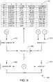
- FIG. 4shows an example method 400 for calculating a time to fill a fuel tank (t final ).
- the value for t finalmay be used, for example, to manage one or more operations at a hydrogen station 100 , such as pressure and/or temperature regulation of the hydrogen gas being dispensed.
- One or more coefficientsare identified at operation 410 .
- a table 412may be used to identify values for a, b, c, and d based on an ambient temperature (T amb ).
- T amban ambient temperature
- a value for T ambis detected by and/or received from the first ambient temperature sensor 228 and/or second ambient temperature sensor 238 . Because ambient temperatures may vary based on time, each set of coefficients may be identified continuously or iteratively (e.g., at a plurality of times) throughout the fill.
- the table 412may be the same or similar to that used in the original MC Formula described in commonly-owned U.S. Pat. No. 9,347,614 entitled “Method and System for Tank Refilling Using Active Fueling Speed Control,” which issued on May 24, 2016 from U.S. Application Ser. No. 14/300,229 filed Jun. 9, 2014 and is incorporated by reference herein in its entirety. Values for a, b, c, and d may also be derived from fueling simulations using the same or similar fueling model with the same or similar assumptions and boundary conditions used in the original MC Formula.
- a first set of coefficients(e.g., a D , b D , c D , d D ) may be identified based on a first location at the hydrogen station 100 (e.g., the dispenser 104 ), and a second set of coefficients (e.g., a N , b N , c N , d N ) may be identified based on a second location at the hydrogen station 100 (e.g., the nozzle 110 ).
- a mass average temperature of the hydrogen gas (MAT)may be identified at operation 420 .
- a value for MATmay be identified based on a mass flow rate of the hydrogen gas ( ⁇ dot over (m) ⁇ ) and a temperature of the hydrogen gas (T). For example, a value for MAT for a time interval (i) may be calculated using Equation [1]:
- MAT ( i )⁇ 1 i ⁇ [ ⁇ ⁇ ⁇ m ( i ) ⁇ 0.5 ⁇ ( T ( i ) + T ( i - 1 ) ) ] ⁇ 1 i ⁇ ⁇ ⁇ ⁇ m ( i ) [ 1 ]
- ⁇ m (i)is a change in mass of the hydrogen gas relative to the previous measurement (i.e., m (i) ⁇ m (i ⁇ 1) );
- T (i)is a temperature of the hydrogen gas according to the current measurement
- T (i ⁇ 1)is a temperature of the hydrogen gas according to the previous measurement.
- a first mass average temperature(e.g., MAT D ) may be identified based on a first change in mass and temperature associated with the first location at the hydrogen station 100 (e.g., ⁇ m D and T D , respectively)
- second mass average temperature(e.g., MAT N ) may be identified based on a second change in mass and temperature associated with the second location at the hydrogen station 100 (e.g., ⁇ m N and T N , respectively).
- Values for ⁇ m D , T D , ⁇ m N , and T Nmay be detected by and/or received from the first mass flow meter 226 , first temperature sensor 222 , second mass flow meter 236 , and second temperature sensor 232 , respectively. Additionally, because flow rates and/or temperatures of the hydrogen gas may vary based on time, each MAT may be identified continuously or iteratively (e.g., at a plurality of times) throughout the fill. In some examples, values for MAT D and MAT N are identified or calculated using a common value for ⁇ m detected by and/or received from a single mass flow meter (e.g., first mass flow meter 226 or second mass flow meter 236 ).
- a control value for t finalis identified at operation 430 using the coefficients identified at operation 410 (e.g., a, b, c, d) and the mass average temperature identified at operation 420 (e.g., MAT).
- ⁇is an adjustment factor to account for variability in a pressure ramp rate (PRR) during fueling; and ⁇ is an adjustment factor to account for a pressure corridor which defines an upper pressure limit above the ramp pressure and a lower pressure limit below the ramp pressure during the fill.
- PRRpressure ramp rate
- a value for beta ( ⁇ )may be calculated using Equation [3]:
- P finalis a predetermined target fill pressure of the hydrogen gas
- P minis a predetermined minimum fill pressure of the hydrogen gas
- P tolis a predetermined fill pressure tolerance.
- thermodynamic parameters throughout the fillensures an efficient and effective fueling process. From a control standpoint, differences between thermodynamic parameters may lead to varying values for t final .
- a first fill timee.g., t final D
- first set of coefficientse.g., a D , b D , c D , d D
- first mass average temperaturee.g., MAT D
- second fill timee.g., t final N
- thermodynamic parameters at the first location at the hydrogen station 100and thermodynamic parameters at the second location at the hydrogen station 100 , both t final D and t final N are calculated, and the lower of the two t final values is identified as the control value.
- the control value for t finalmay be used to control the fueling process throughout the fill. Because MAT D tends to be colder than MAT N at the beginning of a fill, the control value for t final may be initially dictated by t final D . However, MAT N tends to become progressively colder as a fill progresses, lowering t final N . When t final N becomes less than t final D , the control value for t final smoothly and seamlessly switches from being dictated by t final D to being dictated by t final N .
- control value for t finalmay be used to identify PRR at operation 440 and/or a target fill pressure (P) at operation 450 .
- Ptarget fill pressure
- a value for PRRmay be calculated, for example, using Equation [5]:
- PRR( P final - P current ) [ t final ⁇ ( P final - P initial ) ( P final - P min ) - t current ] [ 5 ]
- P currentis a current fill pressure of the hydrogen gas
- P initialis a fill pressure of the hydrogen gas during fueling startup
- t currentis an elapsed fill time
- a value for a target fill pressure for the next time interval (P (i+1) )may be calculated, for example, using Equation [6]:
- P (i)is a fill pressure of the hydrogen gas according to the current measurement
- t (i)is a fill time according to the current measurement
- t (i+1)is a fill time according to the next measurement.
- values for P final , P current , P (i) , P initial , and/or P minmay be detected by and/or received from the first pressure sensor 224 .
- values for P final , P current , P (i) , P initial , and/or P minmay be detected by and/or received from the second pressure sensor 234 .
- a single pressure sensordetects and/or provides values for P final , P current , P (i) , P initial , and/or P min , whether t final is dictated by t final D or t final N .
- inherent margins that exist in the original MC Formulamay be reduced by increasing a fueling rate and/or target fill pressure. Additionally or alternatively, the inherent margins may be reduced by reducing an energy used to pre-cool the hydrogen gas (e.g., by the heat exchanger 108 ) before it is delivered to the dispenser 104 .
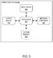
- FIG. 5shows an example computing system 500 configured to perform one or more computing operations. While some examples of the disclosure are illustrated and described herein with reference to the computing system 500 being included in a controller 210 (shown, e.g., in FIG. 1 ), aspects of the disclosure are operable with any computing system (e.g., connection sensor 118 , sensors 120 , first sensors 220 , first temperature sensor 222 , first pressure sensor 224 , first mass flow meter 226 , first ambient temperature sensor 228 , second sensors 230 , second temperature sensor 232 , second pressure sensor 234 , second mass flow meter 236 , second ambient temperature sensor 238 ) that executes instructions to implement the operations and functionality associated with the computing system 500 .
- the computing system 500shows only one example of a computing environment for performing one or more computing operations and is not intended to suggest any limitation as to the scope of use or functionality of the disclosure.
- the computing system 500includes a system memory 510 and a processor 520 coupled to the system memory 510 .
- the system memory 510stores data associated with the control system 200 and computer-executable instructions, and the processor 520 is programmed or configured to execute the computer-executable instructions for implementing aspects of the disclosure using the control system 200 .
- the system memory 510includes one or more computer-readable media that allow information, such as the computer-executable instructions and other data, to be stored and/or retrieved by the processor 520 .
- At least some datamay be associated with one or more fuel tanks, vehicles, fuel types, fuel amounts, fuel temperatures, fuel pressures, flow rates, ambient temperatures, one or more control mechanisms (e.g., heat exchanger 108 , breakaway 114 , first hydrogen flow regulator 240 , second hydrogen flow regulator 242 ), and/or one or more sensors (e.g., connection sensor 118 , sensors 120 , first sensors 220 , first temperature sensor 222 , first pressure sensor 224 , first mass flow meter 226 , first ambient temperature sensor 228 , second sensors 230 , second temperature sensor 232 , second pressure sensor 234 , second mass flow meter 236 , second ambient temperature sensor 238 ) such that the computer-executable instructions enable the processor 520 to manage or control one or more operations of the controller 210 .
- control mechanismse.g., heat exchanger 108 , breakaway 114 , first hydrogen flow regulator 240 , second hydrogen flow regulator 242
- sensorse.g., connection sensor 118 , sensors
- Computer-readable mediamay include computer storage media and communication media.
- Computer storage mediaare tangible and mutually exclusive to communication media.
- the system memory 510may include computer storage media in the form of volatile and/or nonvolatile memory, such as read only memory (ROM) or random access memory (RAM), electrically erasable programmable read-only memory (EEPROM), solid-state storage (SSS), flash memory, a hard disk, a floppy disk, a compact disc (CD), a digital versatile disc (DVD), magnetic tape, or any other medium that may be used to store desired information that may be accessed by the processor 520 .
- Computer storage mediaare implemented in hardware and exclude carrier waves and propagated signals. That is, computer storage media for purposes of this disclosure are not signals per se.
- the processor 520executes the computer-executable instructions to identify a plurality of fuel temperatures, determine a plurality of candidate fill times, and select a control value for controlling a delivery of fuel to the fuel tank.
- the control valuemay be selected, for example, by comparing the candidate fill times and identifying the lowest candidate fill time.
- a state of the control system 200may be monitored (e.g., using one or more sensors 120 ), and one or more control mechanisms (e.g., heat exchanger 108 , breakaway 114 , first hydrogen flow regulator 240 , second hydrogen flow regulator 242 ) may be adjusted based on the monitoring. For example, a flow rate of the hydrogen gas may be adjusted and/or heat may be removed from the hydrogen gas based on the state of the control system 200 .
- the processor 520may include one or more processing units (e.g., in a multi-core configuration). Although the processor 520 is shown separate from the system memory 510 , examples of the disclosure contemplate that the system memory 510 may be onboard the processor 520 , such as in some embedded systems.
- a user or operatormay enter commands and other input into the computing system 500 through one or more input devices 530 (e.g., connection sensor 118 , sensors 120 , first sensors 220 , first temperature sensor 222 , first pressure sensor 224 , first mass flow meter 226 , first ambient temperature sensor 228 , second sensors 230 , second temperature sensor 232 , second pressure sensor 234 , second mass flow meter 236 , second ambient temperature sensor 238 ) coupled to the processor 520 .
- the input devices 530are configured to receive information (e.g., from the user).
- Example input devices 530include, without limitation, a pointing device (e.g., mouse, trackball, touch pad, joystick), a keyboard, a game pad, a controller, a microphone, a camera, a gyroscope, an accelerometer, a position detector, and an electronic digitizer (e.g., on a touchscreen).
- Informationsuch as text, images, video, audio, and the like, may be presented to a user via one or more output devices 540 coupled to the processor 520 .
- the output devices 540are configured to convey information (e.g., to the user).
- Example, output devices 540include, without limitation, a monitor, a projector, a printer, a speaker, a vibrating component.
- an output device 540is integrated with an input device 530 (e.g., a capacitive touch-screen panel, a controller including a vibrating component).
- One or more network components 550may be used to operate the computing system 500 in a networked environment using one or more logical connections.
- Logical connectionsinclude, for example, local area networks and wide area networks (e.g., the Internet).
- the network components 550allow the processor 520 , for example, to convey information to and/or receive information from one or more remote devices, such as another computing system or one or more remote computer storage media.
- Network components 550may include a network adapter, such as a wired or wireless network adapter or a wireless data transceiver.
- Example filling stations and control systems for filling stationsare described herein and illustrated in the accompanying drawings. This written description uses examples to disclose aspects of the disclosure and also to enable a person skilled in the art to practice the aspects, including making or using the above-described systems and executing or performing the above-described methods.
- the actual amount of heat transferred from the fueling hardware to the hydrogen gas throughout the fillis inherently less than the amount of heat assumed to be transferred in the original MC Formula. Examples described herein provide shorter fill times and/or reduced energy usage by taking advantage of down-the-line readings that more-accurately reflect this heat transfer without using in-tank sensors.
Landscapes
- Engineering & Computer Science (AREA)
- Mechanical Engineering (AREA)
- General Engineering & Computer Science (AREA)
- Filling Or Discharging Of Gas Storage Vessels (AREA)
Abstract
Description
where
tfinal=α×β×[a×MAT3+b×MAT2+c×MAT+d] [2]
where
where
tfinal
tfinal
tfinal=minimum[tfinal
where
where
Claims (14)
Priority Applications (1)
| Application Number | Priority Date | Filing Date | Title |
|---|---|---|---|
| US16/530,415US11313514B2 (en) | 2018-12-04 | 2019-08-02 | Method and system for tank refueling using dispenser and nozzle readings |
Applications Claiming Priority (2)
| Application Number | Priority Date | Filing Date | Title |
|---|---|---|---|
| US201862774959P | 2018-12-04 | 2018-12-04 | |
| US16/530,415US11313514B2 (en) | 2018-12-04 | 2019-08-02 | Method and system for tank refueling using dispenser and nozzle readings |
Publications (2)
| Publication Number | Publication Date |
|---|---|
| US20200173607A1 US20200173607A1 (en) | 2020-06-04 |
| US11313514B2true US11313514B2 (en) | 2022-04-26 |
Family
ID=70848838
Family Applications (1)
| Application Number | Title | Priority Date | Filing Date |
|---|---|---|---|
| US16/530,415ActiveUS11313514B2 (en) | 2018-12-04 | 2019-08-02 | Method and system for tank refueling using dispenser and nozzle readings |
Country Status (1)
| Country | Link |
|---|---|
| US (1) | US11313514B2 (en) |
Cited By (1)
| Publication number | Priority date | Publication date | Assignee | Title |
|---|---|---|---|---|
| US12017905B2 (en)* | 2019-03-27 | 2024-06-25 | Luca Greco | Apparatus for preparing and dispensing a lubricating and cooling liquid product for machine tools |
Families Citing this family (8)
| Publication number | Priority date | Publication date | Assignee | Title |
|---|---|---|---|---|
| JP2019158126A (en)* | 2018-03-16 | 2019-09-19 | Jxtgエネルギー株式会社 | Hydrogen fuel filling system and hydrogen fuel filling method |
| JP6600430B1 (en)* | 2019-02-01 | 2019-10-30 | 岩谷産業株式会社 | Inspection device for hydrogen gas dispenser |
| FR3098274B1 (en)* | 2019-07-03 | 2022-01-28 | Air Liquide | Device and method for filling reservoirs. |
| US12135113B1 (en) | 2020-06-15 | 2024-11-05 | William S. Lerner | Hydrogen fueling safety indicator |
| US11572982B1 (en)* | 2020-06-15 | 2023-02-07 | William Seth Lerner | Hydrogen fueling safety indicator |
| FR3113900B1 (en)* | 2020-09-10 | 2022-07-29 | Air Liquide | Gas tank filling station |
| ES2967985T3 (en)* | 2020-12-02 | 2024-05-06 | Its Ingenieurbuero T Steuer | Measurement system to determine the amount of hydrogen emitted as well as a procedure for this |
| AU2022230850B2 (en) | 2021-03-03 | 2025-03-13 | Eneos Corporation | Gas filling device |
Citations (89)
| Publication number | Priority date | Publication date | Assignee | Title |
|---|---|---|---|---|
| US3536109A (en) | 1967-12-18 | 1970-10-27 | Standard Oil Co | Control mechanism for automatic dispensing of motor fuel |
| US4347472A (en) | 1980-10-20 | 1982-08-31 | Lemelson Jerome H | Apparatus and method for charging a battery in a vehicle |
| US4398172A (en) | 1981-06-08 | 1983-08-09 | Eaton Corporation | Vehicle monitor apparatus |
| US4490798A (en) | 1981-12-16 | 1984-12-25 | Art Systems, Inc. | Fuel dispensing and vehicle maintenance system |
| US4527600A (en) | 1982-05-05 | 1985-07-09 | Rockwell International Corporation | Compressed natural gas dispensing system |
| US4934419A (en) | 1988-06-30 | 1990-06-19 | Analytical Instruments Limited | Fleet data monitoring system |
| US5058044A (en) | 1989-03-30 | 1991-10-15 | Auto I.D. Inc. | Automated maintenance checking system |
| US5202617A (en) | 1991-10-15 | 1993-04-13 | Norvik Technologies Inc. | Charging station for electric vehicles |
| US5201819A (en) | 1990-05-10 | 1993-04-13 | Yugen Kaisha Takuma Seiko | Driving wheel elevating apparatus in self-propelled truck |
| US5238030A (en) | 1991-06-27 | 1993-08-24 | Dvco | Method and apparatus for dispensing natural gas |
| US5259424A (en) | 1991-06-27 | 1993-11-09 | Dvco, Inc. | Method and apparatus for dispensing natural gas |
| US5327066A (en) | 1993-05-25 | 1994-07-05 | Intellectual Property Development Associates Of Connecticut, Inc. | Methods and apparatus for dispensing a consumable energy source to a vehicle |
| US5359522A (en) | 1990-05-09 | 1994-10-25 | Ryan Michael C | Fluid delivery control apparatus |
| EP0653585A1 (en) | 1993-11-08 | 1995-05-17 | Maschinenfabrik Sulzer-Burckhardt AG | Process and device for the quick filling of a pressure container with a gaseous fluid |
| US5479966A (en) | 1993-07-26 | 1996-01-02 | Consolidated Natural Gas Service Company, Inc. | Quick fill fuel charge process |
| US5564306A (en) | 1994-05-25 | 1996-10-15 | Marcum Fuel Systems, Inc. | Density compensated gas flow meter |
| US5569922A (en) | 1995-07-26 | 1996-10-29 | Boston Advanced Technologies, Inc. | Portable fuel analyzer for the diagnosis of fuel-related problems on-site at the vehicle service bay |
| US5594318A (en) | 1995-04-10 | 1997-01-14 | Norvik Traction Inc. | Traction battery charging with inductive coupling |
| US5602745A (en) | 1995-01-18 | 1997-02-11 | Gilbarco Inc. | Fuel dispenser electronics design |
| US5628349A (en) | 1995-01-25 | 1997-05-13 | Pinnacle Cng Systems, Llc | System and method for dispensing pressurized gas |
| DE19643801A1 (en) | 1996-10-30 | 1998-05-07 | Sieghard Dr Gall | Gas filling of containers from supply gas store |
| US5750995A (en) | 1996-02-16 | 1998-05-12 | Boston Advanced Technologies, Inc. | Methods and devices for fuel characterization and optimal fuel identification on-site at a fuel delivery dispenser |
| US5762118A (en) | 1996-11-05 | 1998-06-09 | I C E M Enterprises Inc. | Apparatus and method for the cordless remote control of a filling function of a mobile vehicle |
| US5868479A (en) | 1992-08-20 | 1999-02-09 | Knape & Vogt Manufacturing Company | Drawer slide assembly |
| US5868176A (en) | 1997-05-27 | 1999-02-09 | Gas Research Institute | System for controlling the fill of compressed natural gas cylinders |
| US5881779A (en) | 1996-03-20 | 1999-03-16 | Gas Research Institute | Computer readable medium containing software for controlling an automated compressed gas dispensing system |
| US5956259A (en) | 1995-12-08 | 1999-09-21 | Gilbarco Inc. | Intelligent fueling |
| US5971042A (en) | 1997-03-04 | 1999-10-26 | Gilbarco Inc. | Precision fuel dispenser |
| US5970786A (en) | 1997-09-25 | 1999-10-26 | Smith; Robert S. | Method for measuring compressed natural gas |
| US6024137A (en) | 1998-02-18 | 2000-02-15 | R. Strnad Enterprises, Llc | Automatic fueling system and components therefor |
| US6068030A (en) | 1998-10-15 | 2000-05-30 | Tatsuno Corp. | Fueling system |
| US6070156A (en) | 1997-09-26 | 2000-05-30 | Gilbarco Inc. | Providing transaction estimates in a fueling and retail system |
| US6073081A (en) | 1996-12-19 | 2000-06-06 | Messer Griesheim Gmbh | Method and device for monitoring the filling of a cryotank |
| US6089284A (en) | 1998-09-24 | 2000-07-18 | Marconi Commerce Systems Inc. | Preconditioning a fuel dispensing system using a transponder |
| US6185501B1 (en) | 1993-05-25 | 2001-02-06 | Intellectual Property Development Associates Of Connecticut, Inc. | Methods and apparatus for loading or modifying a vehicle database from a remote computer via a communications network and a fuel or current dispenser |
| US6237647B1 (en) | 1998-04-06 | 2001-05-29 | William Pong | Automatic refueling station |
| US6250347B1 (en) | 1999-11-18 | 2001-06-26 | Tatsuno Corporation | Automatic fueling system |
| US6338008B1 (en) | 1998-04-09 | 2002-01-08 | Mobil Oil Corporation | Robotic vehicle servicing system |
| US6343241B1 (en) | 1998-04-09 | 2002-01-29 | Mobil Oil Corporation | Robotic vehicle servicing system |
| US6381514B1 (en) | 1998-08-25 | 2002-04-30 | Marconi Commerce Systems Inc. | Dispenser system for preventing unauthorized fueling |
| US6382269B1 (en) | 2000-02-22 | 2002-05-07 | Tatsuno Corp. | Automatic fueling system |
| EP1205704A1 (en) | 2000-11-08 | 2002-05-15 | GreenField AG | Process for filling a vehicle tank with gas |
| US6394150B1 (en) | 1999-11-10 | 2002-05-28 | Hi-G-Tek Ltd. | Computerized fluid supply systems |
| US6401767B1 (en) | 2001-05-22 | 2002-06-11 | Air Products And Chemicals, Inc. | Apparatus and method for grounding compressed fuel fueling operator |
| US6463967B1 (en) | 2000-11-17 | 2002-10-15 | The Lubrizol Corporation | System for diagnosing, maintaining and reporting the performance and safety condition of apparatus during refueling |
| US6497363B1 (en) | 1998-01-15 | 2002-12-24 | Del-Pak Systems (1983) Ltd. | Electrical connector with identification chip |
| US6598792B1 (en) | 1996-06-28 | 2003-07-29 | Ordicam Recherche Et Development | Method for controlling the supply of fuel and/or the payment for same at a service station and installation used for implementing this method |
| US6619336B2 (en) | 2002-02-14 | 2003-09-16 | Air Products And Chemicals, Inc. | System and method for dispensing pressurized gas |
| US6672340B2 (en)* | 2000-11-08 | 2004-01-06 | Greenfield Ag | Method for filling a vehicle fuel tank with gas |
| US6688342B2 (en) | 2002-02-22 | 2004-02-10 | Tokheim Corporation | Fuel dispenser using infrared technology to facilitate the communication of structured data |
| US6708573B1 (en) | 2002-09-12 | 2004-03-23 | Air Products And Chemicals, Inc. | Process for filling compressed gas fuel dispensers which utilizes volume and density calculations |
| US6727809B1 (en) | 1993-05-25 | 2004-04-27 | Intellectual Property Development Associates Of Connecticut, Inc. | Methods for providing information, messages and advertisements to a user of a fuel pump that is coupled to remote computers through a data communications network |
| US6745801B1 (en) | 2003-03-25 | 2004-06-08 | Air Products And Chemicals, Inc. | Mobile hydrogen generation and supply system |
| US6822551B2 (en) | 2002-11-14 | 2004-11-23 | General Hydrogen Corporation | System for communication with a vehicle in close proximity to a fixed service port |
| US20050178463A1 (en) | 2004-02-12 | 2005-08-18 | Kountz Kenneth J. | Control method for high-pressure hydrogen vehicle fueling station dispensers |
| US6964821B2 (en) | 2000-06-08 | 2005-11-15 | Toyota Jidosha Kabushiki Kaisha | Fuel cell fuel supply system and mobile body |
| WO2005120196A2 (en) | 2004-06-04 | 2005-12-22 | Atlas Copco Secoroc Ab | Disassembleable washer device for down-hole drills |
| US7171989B2 (en) | 2003-10-31 | 2007-02-06 | Cellex Power Products, Inc. | Fuel dispensing system and method |
| US20070090693A1 (en) | 2005-10-25 | 2007-04-26 | Hamilton Sundstrand Corporation | Pulsed power supply with current ripple reduction |
| WO2007077376A2 (en) | 2006-01-06 | 2007-07-12 | L'air Liquide Societe Anonyme Pour L'etude Et L'eyploitation Des Procedes Georges Claude | Method and device for filling pressure gas containers |
| CN101087975A (en) | 2004-12-22 | 2007-12-12 | 乔治洛德方法研究和开发液化空气有限公司 | Method for controlled filling of pressurized gas tanks |
| US20080000542A1 (en) | 2006-06-07 | 2008-01-03 | Joseph Perry Cohen | Hydrogen dispenser with user-selectable hydrogen dispensing rate algorithms |
| US7406987B2 (en) | 2002-09-25 | 2008-08-05 | Taiyo Nippon Sanso Corporation | Apparatus and method for filling fuel |
| US20080185068A1 (en) | 2007-01-04 | 2008-08-07 | Joseph Perry Cohen | Hydrogen dispensing station and method of operating the same |
| US20080231836A1 (en) | 2005-08-02 | 2008-09-25 | Societe Bic | Fuel Cell with Fuel Monitoring System and Method of Use |
| US20090044877A1 (en) | 2007-06-22 | 2009-02-19 | Jean-Yves Faudou | Method for controlled filling of pressurized gas tanks |
| US7523770B2 (en) | 2005-12-12 | 2009-04-28 | Exxonmobil Research And Enginnering Company | Service station for serving requirements of multiple vehicle technologies |
| US7543611B2 (en) | 2002-03-26 | 2009-06-09 | Identic Ab | Method and system for refuelling |
| CN101488576A (en) | 2003-07-25 | 2009-07-22 | 丰田自动车株式会社 | Gas supply system |
| US20090205745A1 (en) | 2008-02-20 | 2009-08-20 | Air Products And Chemicals, Inc. | Compressor Fill Method And Apparatus |
| US7647194B1 (en) | 2008-08-13 | 2010-01-12 | Daniel Glenn Casey | Method for calculating hydrogen temperature during vehicle fueling |
| US7671482B2 (en) | 2007-02-02 | 2010-03-02 | Gm Global Technology Operations, Inc. | Hydrogen powered vehicle refueling strategy |
| US20100121551A1 (en) | 2008-11-10 | 2010-05-13 | International Business Machines Corporation | Method, system, and program product for facilitating vehicle fueling based on vehicle state |
| US20100185360A1 (en) | 2007-07-04 | 2010-07-22 | Thor Windbergs | Method and device for detecting a tank level |
| US20100241470A1 (en) | 2009-03-18 | 2010-09-23 | Smith Christopher W | System and apparatus for rapid recharging of electric batteries |
| US7820313B2 (en) | 2006-10-02 | 2010-10-26 | Motorola, Inc. | Fuel source recognition and gating apparatus and associated method |
| US20100294393A1 (en) | 2007-09-10 | 2010-11-25 | L'air Liquide Societe Anonyme Pour L'etude Et L'ex Ploitation Des Procedes Georges Claude | Method for Filling a Pressurized Gas Container |
| US20100307636A1 (en)* | 2009-06-09 | 2010-12-09 | Honda Motor Co., Ltd. | Hydrogen filling apparatus and hydrogen filling method |
| US20110035049A1 (en) | 2009-08-10 | 2011-02-10 | Ronnie Gene Barrett | Fuel delivery information system |
| US20110100507A1 (en) | 2008-07-02 | 2011-05-05 | Petratec International Ltd. | Apparatus and method for controlling the dispensing of a liquid into a container, particularly useful in vehicle fuel dispensing systems |
| US20110259469A1 (en)* | 2010-04-21 | 2011-10-27 | Harty Ryan | Method and System for Tank Refilling |
| US20120192989A1 (en) | 2011-01-27 | 2012-08-02 | Gb Global Technology Operations Llc | Compressed hydrogen fueling control valve |
| US20120227864A1 (en)* | 2009-11-18 | 2012-09-13 | Tomoyuki Mori | Gas filling system, gas filling method, and vehicle |
| US20120267002A1 (en)* | 2009-10-21 | 2012-10-25 | Nel Hydrogen As | Method for the operation and control of gas filling |
| US20130014854A1 (en)* | 2010-01-25 | 2013-01-17 | Tomoyuki Mori | Fuel gas station, fuel gas filling system, and fuel gas supplying method |
| US20140290790A1 (en)* | 2010-04-21 | 2014-10-02 | Honda Motor Co., Ltd. | Method and system for tank refilling using active fueling speed control |
| US20150308621A1 (en)* | 2010-04-21 | 2015-10-29 | Honda Motor Co., Ltd. | Method and system for tank refilling using active fueling speed control |
| US20160305611A1 (en)* | 2015-04-14 | 2016-10-20 | Honda Motor Co., Ltd. | Fuel filling system and fuel filling method thereof |
| US20180038550A1 (en)* | 2016-08-05 | 2018-02-08 | Toyota Jidosha Kabushiki Kaisha | Gas filling system |
- 2019
- 2019-08-02USUS16/530,415patent/US11313514B2/enactiveActive
Patent Citations (103)
| Publication number | Priority date | Publication date | Assignee | Title |
|---|---|---|---|---|
| US3536109A (en) | 1967-12-18 | 1970-10-27 | Standard Oil Co | Control mechanism for automatic dispensing of motor fuel |
| US4347472A (en) | 1980-10-20 | 1982-08-31 | Lemelson Jerome H | Apparatus and method for charging a battery in a vehicle |
| US4398172A (en) | 1981-06-08 | 1983-08-09 | Eaton Corporation | Vehicle monitor apparatus |
| US4490798A (en) | 1981-12-16 | 1984-12-25 | Art Systems, Inc. | Fuel dispensing and vehicle maintenance system |
| US4527600A (en) | 1982-05-05 | 1985-07-09 | Rockwell International Corporation | Compressed natural gas dispensing system |
| US4934419A (en) | 1988-06-30 | 1990-06-19 | Analytical Instruments Limited | Fleet data monitoring system |
| US5058044A (en) | 1989-03-30 | 1991-10-15 | Auto I.D. Inc. | Automated maintenance checking system |
| US5359522A (en) | 1990-05-09 | 1994-10-25 | Ryan Michael C | Fluid delivery control apparatus |
| US5201819A (en) | 1990-05-10 | 1993-04-13 | Yugen Kaisha Takuma Seiko | Driving wheel elevating apparatus in self-propelled truck |
| US5238030A (en) | 1991-06-27 | 1993-08-24 | Dvco | Method and apparatus for dispensing natural gas |
| US5259424A (en) | 1991-06-27 | 1993-11-09 | Dvco, Inc. | Method and apparatus for dispensing natural gas |
| US5202617A (en) | 1991-10-15 | 1993-04-13 | Norvik Technologies Inc. | Charging station for electric vehicles |
| US5868479A (en) | 1992-08-20 | 1999-02-09 | Knape & Vogt Manufacturing Company | Drawer slide assembly |
| US5327066A (en) | 1993-05-25 | 1994-07-05 | Intellectual Property Development Associates Of Connecticut, Inc. | Methods and apparatus for dispensing a consumable energy source to a vehicle |
| US6727809B1 (en) | 1993-05-25 | 2004-04-27 | Intellectual Property Development Associates Of Connecticut, Inc. | Methods for providing information, messages and advertisements to a user of a fuel pump that is coupled to remote computers through a data communications network |
| US6185501B1 (en) | 1993-05-25 | 2001-02-06 | Intellectual Property Development Associates Of Connecticut, Inc. | Methods and apparatus for loading or modifying a vehicle database from a remote computer via a communications network and a fuel or current dispenser |
| US5479966A (en) | 1993-07-26 | 1996-01-02 | Consolidated Natural Gas Service Company, Inc. | Quick fill fuel charge process |
| US5570729A (en) | 1993-11-08 | 1996-11-05 | Maschinenfabrik Sulzer-Burckhardt Ag | Method and apparatus for the rapid tanking of a pressure container with a gaseous medium |
| EP0653585A1 (en) | 1993-11-08 | 1995-05-17 | Maschinenfabrik Sulzer-Burckhardt AG | Process and device for the quick filling of a pressure container with a gaseous fluid |
| US5564306A (en) | 1994-05-25 | 1996-10-15 | Marcum Fuel Systems, Inc. | Density compensated gas flow meter |
| US5602745A (en) | 1995-01-18 | 1997-02-11 | Gilbarco Inc. | Fuel dispenser electronics design |
| US5628349A (en) | 1995-01-25 | 1997-05-13 | Pinnacle Cng Systems, Llc | System and method for dispensing pressurized gas |
| US5594318A (en) | 1995-04-10 | 1997-01-14 | Norvik Traction Inc. | Traction battery charging with inductive coupling |
| US5569922A (en) | 1995-07-26 | 1996-10-29 | Boston Advanced Technologies, Inc. | Portable fuel analyzer for the diagnosis of fuel-related problems on-site at the vehicle service bay |
| US5956259A (en) | 1995-12-08 | 1999-09-21 | Gilbarco Inc. | Intelligent fueling |
| US5750995A (en) | 1996-02-16 | 1998-05-12 | Boston Advanced Technologies, Inc. | Methods and devices for fuel characterization and optimal fuel identification on-site at a fuel delivery dispenser |
| US5881779A (en) | 1996-03-20 | 1999-03-16 | Gas Research Institute | Computer readable medium containing software for controlling an automated compressed gas dispensing system |
| US6598792B1 (en) | 1996-06-28 | 2003-07-29 | Ordicam Recherche Et Development | Method for controlling the supply of fuel and/or the payment for same at a service station and installation used for implementing this method |
| DE19643801A1 (en) | 1996-10-30 | 1998-05-07 | Sieghard Dr Gall | Gas filling of containers from supply gas store |
| US5762118A (en) | 1996-11-05 | 1998-06-09 | I C E M Enterprises Inc. | Apparatus and method for the cordless remote control of a filling function of a mobile vehicle |
| US6073081A (en) | 1996-12-19 | 2000-06-06 | Messer Griesheim Gmbh | Method and device for monitoring the filling of a cryotank |
| US5971042A (en) | 1997-03-04 | 1999-10-26 | Gilbarco Inc. | Precision fuel dispenser |
| US5868176A (en) | 1997-05-27 | 1999-02-09 | Gas Research Institute | System for controlling the fill of compressed natural gas cylinders |
| US5970786A (en) | 1997-09-25 | 1999-10-26 | Smith; Robert S. | Method for measuring compressed natural gas |
| US6070156A (en) | 1997-09-26 | 2000-05-30 | Gilbarco Inc. | Providing transaction estimates in a fueling and retail system |
| US6497363B1 (en) | 1998-01-15 | 2002-12-24 | Del-Pak Systems (1983) Ltd. | Electrical connector with identification chip |
| US6024137A (en) | 1998-02-18 | 2000-02-15 | R. Strnad Enterprises, Llc | Automatic fueling system and components therefor |
| US6237647B1 (en) | 1998-04-06 | 2001-05-29 | William Pong | Automatic refueling station |
| US6343241B1 (en) | 1998-04-09 | 2002-01-29 | Mobil Oil Corporation | Robotic vehicle servicing system |
| US6338008B1 (en) | 1998-04-09 | 2002-01-08 | Mobil Oil Corporation | Robotic vehicle servicing system |
| US6381514B1 (en) | 1998-08-25 | 2002-04-30 | Marconi Commerce Systems Inc. | Dispenser system for preventing unauthorized fueling |
| US6089284A (en) | 1998-09-24 | 2000-07-18 | Marconi Commerce Systems Inc. | Preconditioning a fuel dispensing system using a transponder |
| US6068030A (en) | 1998-10-15 | 2000-05-30 | Tatsuno Corp. | Fueling system |
| US6394150B1 (en) | 1999-11-10 | 2002-05-28 | Hi-G-Tek Ltd. | Computerized fluid supply systems |
| US6250347B1 (en) | 1999-11-18 | 2001-06-26 | Tatsuno Corporation | Automatic fueling system |
| US6382269B1 (en) | 2000-02-22 | 2002-05-07 | Tatsuno Corp. | Automatic fueling system |
| US6964821B2 (en) | 2000-06-08 | 2005-11-15 | Toyota Jidosha Kabushiki Kaisha | Fuel cell fuel supply system and mobile body |
| US6672340B2 (en)* | 2000-11-08 | 2004-01-06 | Greenfield Ag | Method for filling a vehicle fuel tank with gas |
| EP1205704A1 (en) | 2000-11-08 | 2002-05-15 | GreenField AG | Process for filling a vehicle tank with gas |
| US6463967B1 (en) | 2000-11-17 | 2002-10-15 | The Lubrizol Corporation | System for diagnosing, maintaining and reporting the performance and safety condition of apparatus during refueling |
| US6401767B1 (en) | 2001-05-22 | 2002-06-11 | Air Products And Chemicals, Inc. | Apparatus and method for grounding compressed fuel fueling operator |
| US6619336B2 (en) | 2002-02-14 | 2003-09-16 | Air Products And Chemicals, Inc. | System and method for dispensing pressurized gas |
| US6688342B2 (en) | 2002-02-22 | 2004-02-10 | Tokheim Corporation | Fuel dispenser using infrared technology to facilitate the communication of structured data |
| US7543611B2 (en) | 2002-03-26 | 2009-06-09 | Identic Ab | Method and system for refuelling |
| US6708573B1 (en) | 2002-09-12 | 2004-03-23 | Air Products And Chemicals, Inc. | Process for filling compressed gas fuel dispensers which utilizes volume and density calculations |
| US7406987B2 (en) | 2002-09-25 | 2008-08-05 | Taiyo Nippon Sanso Corporation | Apparatus and method for filling fuel |
| US20080289720A1 (en) | 2002-09-25 | 2008-11-27 | Naoyuki Takano | Apparatus and method for filling fuel |
| US6822551B2 (en) | 2002-11-14 | 2004-11-23 | General Hydrogen Corporation | System for communication with a vehicle in close proximity to a fixed service port |
| US6745801B1 (en) | 2003-03-25 | 2004-06-08 | Air Products And Chemicals, Inc. | Mobile hydrogen generation and supply system |
| CN101488576A (en) | 2003-07-25 | 2009-07-22 | 丰田自动车株式会社 | Gas supply system |
| US7171989B2 (en) | 2003-10-31 | 2007-02-06 | Cellex Power Products, Inc. | Fuel dispensing system and method |
| US7412994B2 (en) | 2003-10-31 | 2008-08-19 | Cellex Power Products, Inc. | Fuel dispensing system and method |
| US20050178463A1 (en) | 2004-02-12 | 2005-08-18 | Kountz Kenneth J. | Control method for high-pressure hydrogen vehicle fueling station dispensers |
| US7059364B2 (en) | 2004-02-12 | 2006-06-13 | Gas Technology Institute | Control method for high-pressure hydrogen vehicle fueling station dispensers |
| WO2005120196A2 (en) | 2004-06-04 | 2005-12-22 | Atlas Copco Secoroc Ab | Disassembleable washer device for down-hole drills |
| WO2005120196A3 (en) | 2004-06-04 | 2006-12-21 | Atlas Copco Secoroc Ab | Disassembleable washer device for down-hole drills |
| EP1831597A2 (en) | 2004-06-04 | 2007-09-12 | Atlas Copco Secoroc AB | Disassembleable washer device for down-hole drills |
| CN101087975A (en) | 2004-12-22 | 2007-12-12 | 乔治洛德方法研究和开发液化空气有限公司 | Method for controlled filling of pressurized gas tanks |
| US20080231836A1 (en) | 2005-08-02 | 2008-09-25 | Societe Bic | Fuel Cell with Fuel Monitoring System and Method of Use |
| US20070090693A1 (en) | 2005-10-25 | 2007-04-26 | Hamilton Sundstrand Corporation | Pulsed power supply with current ripple reduction |
| US7523770B2 (en) | 2005-12-12 | 2009-04-28 | Exxonmobil Research And Enginnering Company | Service station for serving requirements of multiple vehicle technologies |
| WO2007077376A3 (en) | 2006-01-06 | 2007-10-25 | Air Liquide | Method and device for filling pressure gas containers |
| US20090107577A1 (en)* | 2006-01-06 | 2009-04-30 | L'air Liquide Societe Anonyme Pour L'etude Et L'exploitation Des Procedes Georges Claude | Method and Device for Filling Pressure Gas Containers |
| WO2007077376A2 (en) | 2006-01-06 | 2007-07-12 | L'air Liquide Societe Anonyme Pour L'etude Et L'eyploitation Des Procedes Georges Claude | Method and device for filling pressure gas containers |
| US8360112B2 (en) | 2006-01-06 | 2013-01-29 | L'air Liquide Societe Anonyme Pour L'etude Et L'exploitation Des Procedes Georges Claude | Method and device for filling pressure gas containers |
| US20080000542A1 (en) | 2006-06-07 | 2008-01-03 | Joseph Perry Cohen | Hydrogen dispenser with user-selectable hydrogen dispensing rate algorithms |
| US7921883B2 (en) | 2006-06-07 | 2011-04-12 | Air Products And Chemicals, Inc. | Hydrogen dispenser with user-selectable hydrogen dispensing rate algorithms |
| US7820313B2 (en) | 2006-10-02 | 2010-10-26 | Motorola, Inc. | Fuel source recognition and gating apparatus and associated method |
| US20080185068A1 (en) | 2007-01-04 | 2008-08-07 | Joseph Perry Cohen | Hydrogen dispensing station and method of operating the same |
| US7671482B2 (en) | 2007-02-02 | 2010-03-02 | Gm Global Technology Operations, Inc. | Hydrogen powered vehicle refueling strategy |
| US20090044877A1 (en) | 2007-06-22 | 2009-02-19 | Jean-Yves Faudou | Method for controlled filling of pressurized gas tanks |
| US20100185360A1 (en) | 2007-07-04 | 2010-07-22 | Thor Windbergs | Method and device for detecting a tank level |
| US8517062B2 (en) | 2007-09-10 | 2013-08-27 | L'air Liquide Societe Anonyme Pour L'etude Et L'exploitation Des Procedes Georges Claude | Method for filling a pressurized gas container |
| US20100294393A1 (en) | 2007-09-10 | 2010-11-25 | L'air Liquide Societe Anonyme Pour L'etude Et L'ex Ploitation Des Procedes Georges Claude | Method for Filling a Pressurized Gas Container |
| US20090205745A1 (en) | 2008-02-20 | 2009-08-20 | Air Products And Chemicals, Inc. | Compressor Fill Method And Apparatus |
| EP2093475A1 (en) | 2008-02-20 | 2009-08-26 | Air Products and Chemicals, Inc. | Compressor fill method and apparatus |
| US20110100507A1 (en) | 2008-07-02 | 2011-05-05 | Petratec International Ltd. | Apparatus and method for controlling the dispensing of a liquid into a container, particularly useful in vehicle fuel dispensing systems |
| US7647194B1 (en) | 2008-08-13 | 2010-01-12 | Daniel Glenn Casey | Method for calculating hydrogen temperature during vehicle fueling |
| US20100121551A1 (en) | 2008-11-10 | 2010-05-13 | International Business Machines Corporation | Method, system, and program product for facilitating vehicle fueling based on vehicle state |
| US20100241470A1 (en) | 2009-03-18 | 2010-09-23 | Smith Christopher W | System and apparatus for rapid recharging of electric batteries |
| US20100307636A1 (en)* | 2009-06-09 | 2010-12-09 | Honda Motor Co., Ltd. | Hydrogen filling apparatus and hydrogen filling method |
| US20110035049A1 (en) | 2009-08-10 | 2011-02-10 | Ronnie Gene Barrett | Fuel delivery information system |
| US20120267002A1 (en)* | 2009-10-21 | 2012-10-25 | Nel Hydrogen As | Method for the operation and control of gas filling |
| US20120227864A1 (en)* | 2009-11-18 | 2012-09-13 | Tomoyuki Mori | Gas filling system, gas filling method, and vehicle |
| US20130014854A1 (en)* | 2010-01-25 | 2013-01-17 | Tomoyuki Mori | Fuel gas station, fuel gas filling system, and fuel gas supplying method |
| US20110259469A1 (en)* | 2010-04-21 | 2011-10-27 | Harty Ryan | Method and System for Tank Refilling |
| US8783303B2 (en) | 2010-04-21 | 2014-07-22 | Ryan HARTY | Method and system for tank refilling |
| US20140290790A1 (en)* | 2010-04-21 | 2014-10-02 | Honda Motor Co., Ltd. | Method and system for tank refilling using active fueling speed control |
| US20150308621A1 (en)* | 2010-04-21 | 2015-10-29 | Honda Motor Co., Ltd. | Method and system for tank refilling using active fueling speed control |
| US9347614B2 (en) | 2010-04-21 | 2016-05-24 | Honda Motor Co., Ltd. | Method and system for tank refilling using active fueling speed control |
| US20120192989A1 (en) | 2011-01-27 | 2012-08-02 | Gb Global Technology Operations Llc | Compressed hydrogen fueling control valve |
| US20160305611A1 (en)* | 2015-04-14 | 2016-10-20 | Honda Motor Co., Ltd. | Fuel filling system and fuel filling method thereof |
| US20180038550A1 (en)* | 2016-08-05 | 2018-02-08 | Toyota Jidosha Kabushiki Kaisha | Gas filling system |
Cited By (1)
| Publication number | Priority date | Publication date | Assignee | Title |
|---|---|---|---|---|
| US12017905B2 (en)* | 2019-03-27 | 2024-06-25 | Luca Greco | Apparatus for preparing and dispensing a lubricating and cooling liquid product for machine tools |
Also Published As
| Publication number | Publication date |
|---|---|
| US20200173607A1 (en) | 2020-06-04 |
Similar Documents
| Publication | Publication Date | Title |
|---|---|---|
| US11313514B2 (en) | Method and system for tank refueling using dispenser and nozzle readings | |
| US11339926B2 (en) | Methods and systems for improving hydrogen refueling | |
| US9605804B2 (en) | Method and system for tank refilling using active fueling speed control | |
| JP6001600B2 (en) | System for controlling gas supply unit and gas filling method | |
| CN102282410B (en) | Gas filling system | |
| US9222620B2 (en) | Method and system for tank refilling | |
| US9347612B2 (en) | Method and system for tank refilling using active fueling speed control | |
| US9347614B2 (en) | Method and system for tank refilling using active fueling speed control | |
| JP6327341B2 (en) | Fuel gas filling system and fuel gas filling method | |
| JP5328617B2 (en) | Gas filling system, gas filling method, vehicle | |
| US9880013B2 (en) | Method and system for vehicle refueling | |
| CN102472432A (en) | Gas filling system and gas filling apparatus | |
| US20180335181A1 (en) | Method of refueling a hydrogen vehicle | |
| US9371071B2 (en) | Method for refueling motor vehicles | |
| JP2019527797A (en) | Method for adjusting the temperature and / or pressure of fuel, in particular hydrogen, in a plurality of pressure vessels of a vehicle to the current temperature target value and / or the current pressure target value before the pressure vessel filling step | |
| JP2011122657A (en) | Fuel gas station, fuel gas filling system, and fuel gas filling method | |
| WO2014150320A1 (en) | Improved method and system for tank refilling using active fueling speed control | |
| US9546892B2 (en) | Methods and systems for estimation of propellant transfer in an ion propulsion system | |
| CN106458012B (en) | Method for controlling a filling operation of a vehicle liquid storage system | |
| US9212783B2 (en) | Method and system for tank refilling | |
| CN108019288A (en) | System and method for for vehicle gaseous fuel management | |
| JP6308006B2 (en) | Fuel gas filling system and fuel gas filling method | |
| JP2025502325A (en) | Method and device for detecting possible throttling losses in a hydrogen tank system - Patents.com | |
| CN107758599B (en) | Controlling vehicle refueling operations | |
| WO2014200959A2 (en) | Improved method and system for tank refilling using active fueling speed control |
Legal Events
| Date | Code | Title | Description |
|---|---|---|---|
| FEPP | Fee payment procedure | Free format text:ENTITY STATUS SET TO UNDISCOUNTED (ORIGINAL EVENT CODE: BIG.); ENTITY STATUS OF PATENT OWNER: LARGE ENTITY | |
| STPP | Information on status: patent application and granting procedure in general | Free format text:NON FINAL ACTION MAILED | |
| STPP | Information on status: patent application and granting procedure in general | Free format text:RESPONSE TO NON-FINAL OFFICE ACTION ENTERED AND FORWARDED TO EXAMINER | |
| STPP | Information on status: patent application and granting procedure in general | Free format text:FINAL REJECTION MAILED | |
| STPP | Information on status: patent application and granting procedure in general | Free format text:DOCKETED NEW CASE - READY FOR EXAMINATION | |
| STPP | Information on status: patent application and granting procedure in general | Free format text:NOTICE OF ALLOWANCE MAILED -- APPLICATION RECEIVED IN OFFICE OF PUBLICATIONS | |
| STPP | Information on status: patent application and granting procedure in general | Free format text:PUBLICATIONS -- ISSUE FEE PAYMENT RECEIVED | |
| STPP | Information on status: patent application and granting procedure in general | Free format text:PUBLICATIONS -- ISSUE FEE PAYMENT VERIFIED | |
| STCF | Information on status: patent grant | Free format text:PATENTED CASE | |
| MAFP | Maintenance fee payment | Free format text:PAYMENT OF MAINTENANCE FEE, 4TH YEAR, LARGE ENTITY (ORIGINAL EVENT CODE: M1551); ENTITY STATUS OF PATENT OWNER: LARGE ENTITY Year of fee payment:4 |