US11311882B2 - Digital microfluidics devices and methods of using them - Google Patents
Digital microfluidics devices and methods of using themDownload PDFInfo
- Publication number
- US11311882B2 US11311882B2US16/259,984US201916259984AUS11311882B2US 11311882 B2US11311882 B2US 11311882B2US 201916259984 AUS201916259984 AUS 201916259984AUS 11311882 B2US11311882 B2US 11311882B2
- Authority
- US
- United States
- Prior art keywords
- cartridge
- top plate
- air gap
- dmf
- electrodes
- Prior art date
- Legal status (The legal status is an assumption and is not a legal conclusion. Google has not performed a legal analysis and makes no representation as to the accuracy of the status listed.)
- Active
Links
Images


Classifications
- B—PERFORMING OPERATIONS; TRANSPORTING
- B01—PHYSICAL OR CHEMICAL PROCESSES OR APPARATUS IN GENERAL
- B01L—CHEMICAL OR PHYSICAL LABORATORY APPARATUS FOR GENERAL USE
- B01L3/00—Containers or dishes for laboratory use, e.g. laboratory glassware; Droppers
- B01L3/50—Containers for the purpose of retaining a material to be analysed, e.g. test tubes
- B01L3/502—Containers for the purpose of retaining a material to be analysed, e.g. test tubes with fluid transport, e.g. in multi-compartment structures
- B01L3/5027—Containers for the purpose of retaining a material to be analysed, e.g. test tubes with fluid transport, e.g. in multi-compartment structures by integrated microfluidic structures, i.e. dimensions of channels and chambers are such that surface tension forces are important, e.g. lab-on-a-chip
- B01L3/502769—Containers for the purpose of retaining a material to be analysed, e.g. test tubes with fluid transport, e.g. in multi-compartment structures by integrated microfluidic structures, i.e. dimensions of channels and chambers are such that surface tension forces are important, e.g. lab-on-a-chip characterised by multiphase flow arrangements
- B01L3/502784—Containers for the purpose of retaining a material to be analysed, e.g. test tubes with fluid transport, e.g. in multi-compartment structures by integrated microfluidic structures, i.e. dimensions of channels and chambers are such that surface tension forces are important, e.g. lab-on-a-chip characterised by multiphase flow arrangements specially adapted for droplet or plug flow, e.g. digital microfluidics
- B01L3/502792—Containers for the purpose of retaining a material to be analysed, e.g. test tubes with fluid transport, e.g. in multi-compartment structures by integrated microfluidic structures, i.e. dimensions of channels and chambers are such that surface tension forces are important, e.g. lab-on-a-chip characterised by multiphase flow arrangements specially adapted for droplet or plug flow, e.g. digital microfluidics for moving individual droplets on a plate, e.g. by locally altering surface tension
- C—CHEMISTRY; METALLURGY
- C12—BIOCHEMISTRY; BEER; SPIRITS; WINE; VINEGAR; MICROBIOLOGY; ENZYMOLOGY; MUTATION OR GENETIC ENGINEERING
- C12M—APPARATUS FOR ENZYMOLOGY OR MICROBIOLOGY; APPARATUS FOR CULTURING MICROORGANISMS FOR PRODUCING BIOMASS, FOR GROWING CELLS OR FOR OBTAINING FERMENTATION OR METABOLIC PRODUCTS, i.e. BIOREACTORS OR FERMENTERS
- C12M1/00—Apparatus for enzymology or microbiology
- C—CHEMISTRY; METALLURGY
- C12—BIOCHEMISTRY; BEER; SPIRITS; WINE; VINEGAR; MICROBIOLOGY; ENZYMOLOGY; MUTATION OR GENETIC ENGINEERING
- C12M—APPARATUS FOR ENZYMOLOGY OR MICROBIOLOGY; APPARATUS FOR CULTURING MICROORGANISMS FOR PRODUCING BIOMASS, FOR GROWING CELLS OR FOR OBTAINING FERMENTATION OR METABOLIC PRODUCTS, i.e. BIOREACTORS OR FERMENTERS
- C12M23/00—Constructional details, e.g. recesses, hinges
- C12M23/02—Form or structure of the vessel
- C12M23/16—Microfluidic devices; Capillary tubes
- C—CHEMISTRY; METALLURGY
- C12—BIOCHEMISTRY; BEER; SPIRITS; WINE; VINEGAR; MICROBIOLOGY; ENZYMOLOGY; MUTATION OR GENETIC ENGINEERING
- C12M—APPARATUS FOR ENZYMOLOGY OR MICROBIOLOGY; APPARATUS FOR CULTURING MICROORGANISMS FOR PRODUCING BIOMASS, FOR GROWING CELLS OR FOR OBTAINING FERMENTATION OR METABOLIC PRODUCTS, i.e. BIOREACTORS OR FERMENTERS
- C12M23/00—Constructional details, e.g. recesses, hinges
- C12M23/40—Manifolds; Distribution pieces
- H—ELECTRICITY
- H01—ELECTRIC ELEMENTS
- H01L—SEMICONDUCTOR DEVICES NOT COVERED BY CLASS H10
- H01L21/00—Processes or apparatus adapted for the manufacture or treatment of semiconductor or solid state devices or of parts thereof
- H01L21/70—Manufacture or treatment of devices consisting of a plurality of solid state components formed in or on a common substrate or of parts thereof; Manufacture of integrated circuit devices or of parts thereof
- H01L21/71—Manufacture of specific parts of devices defined in group H01L21/70
- H01L21/768—Applying interconnections to be used for carrying current between separate components within a device comprising conductors and dielectrics
- B—PERFORMING OPERATIONS; TRANSPORTING
- B01—PHYSICAL OR CHEMICAL PROCESSES OR APPARATUS IN GENERAL
- B01L—CHEMICAL OR PHYSICAL LABORATORY APPARATUS FOR GENERAL USE
- B01L2200/00—Solutions for specific problems relating to chemical or physical laboratory apparatus
- B01L2200/02—Adapting objects or devices to another
- B01L2200/025—Align devices or objects to ensure defined positions relative to each other
- B—PERFORMING OPERATIONS; TRANSPORTING
- B01—PHYSICAL OR CHEMICAL PROCESSES OR APPARATUS IN GENERAL
- B01L—CHEMICAL OR PHYSICAL LABORATORY APPARATUS FOR GENERAL USE
- B01L2200/00—Solutions for specific problems relating to chemical or physical laboratory apparatus
- B01L2200/02—Adapting objects or devices to another
- B01L2200/026—Fluid interfacing between devices or objects, e.g. connectors, inlet details
- B01L2200/027—Fluid interfacing between devices or objects, e.g. connectors, inlet details for microfluidic devices
- B—PERFORMING OPERATIONS; TRANSPORTING
- B01—PHYSICAL OR CHEMICAL PROCESSES OR APPARATUS IN GENERAL
- B01L—CHEMICAL OR PHYSICAL LABORATORY APPARATUS FOR GENERAL USE
- B01L2200/00—Solutions for specific problems relating to chemical or physical laboratory apparatus
- B01L2200/04—Exchange or ejection of cartridges, containers or reservoirs
- B—PERFORMING OPERATIONS; TRANSPORTING
- B01—PHYSICAL OR CHEMICAL PROCESSES OR APPARATUS IN GENERAL
- B01L—CHEMICAL OR PHYSICAL LABORATORY APPARATUS FOR GENERAL USE
- B01L2200/00—Solutions for specific problems relating to chemical or physical laboratory apparatus
- B01L2200/06—Fluid handling related problems
- B01L2200/0605—Metering of fluids
- B—PERFORMING OPERATIONS; TRANSPORTING
- B01—PHYSICAL OR CHEMICAL PROCESSES OR APPARATUS IN GENERAL
- B01L—CHEMICAL OR PHYSICAL LABORATORY APPARATUS FOR GENERAL USE
- B01L2200/00—Solutions for specific problems relating to chemical or physical laboratory apparatus
- B01L2200/10—Integrating sample preparation and analysis in single entity, e.g. lab-on-a-chip concept
- B—PERFORMING OPERATIONS; TRANSPORTING
- B01—PHYSICAL OR CHEMICAL PROCESSES OR APPARATUS IN GENERAL
- B01L—CHEMICAL OR PHYSICAL LABORATORY APPARATUS FOR GENERAL USE
- B01L2200/00—Solutions for specific problems relating to chemical or physical laboratory apparatus
- B01L2200/14—Process control and prevention of errors
- B01L2200/142—Preventing evaporation
- B—PERFORMING OPERATIONS; TRANSPORTING
- B01—PHYSICAL OR CHEMICAL PROCESSES OR APPARATUS IN GENERAL
- B01L—CHEMICAL OR PHYSICAL LABORATORY APPARATUS FOR GENERAL USE
- B01L2300/00—Additional constructional details
- B01L2300/02—Identification, exchange or storage of information
- B01L2300/023—Sending and receiving of information, e.g. using bluetooth
- B—PERFORMING OPERATIONS; TRANSPORTING
- B01—PHYSICAL OR CHEMICAL PROCESSES OR APPARATUS IN GENERAL
- B01L—CHEMICAL OR PHYSICAL LABORATORY APPARATUS FOR GENERAL USE
- B01L2300/00—Additional constructional details
- B01L2300/06—Auxiliary integrated devices, integrated components
- B01L2300/0627—Sensor or part of a sensor is integrated
- B01L2300/0645—Electrodes
- B—PERFORMING OPERATIONS; TRANSPORTING
- B01—PHYSICAL OR CHEMICAL PROCESSES OR APPARATUS IN GENERAL
- B01L—CHEMICAL OR PHYSICAL LABORATORY APPARATUS FOR GENERAL USE
- B01L2300/00—Additional constructional details
- B01L2300/08—Geometry, shape and general structure
- B01L2300/0861—Configuration of multiple channels and/or chambers in a single devices
- B01L2300/0867—Multiple inlets and one sample wells, e.g. mixing, dilution
- B—PERFORMING OPERATIONS; TRANSPORTING
- B01—PHYSICAL OR CHEMICAL PROCESSES OR APPARATUS IN GENERAL
- B01L—CHEMICAL OR PHYSICAL LABORATORY APPARATUS FOR GENERAL USE
- B01L2300/00—Additional constructional details
- B01L2300/08—Geometry, shape and general structure
- B01L2300/0861—Configuration of multiple channels and/or chambers in a single devices
- B01L2300/0883—Serpentine channels
- B—PERFORMING OPERATIONS; TRANSPORTING
- B01—PHYSICAL OR CHEMICAL PROCESSES OR APPARATUS IN GENERAL
- B01L—CHEMICAL OR PHYSICAL LABORATORY APPARATUS FOR GENERAL USE
- B01L2300/00—Additional constructional details
- B01L2300/08—Geometry, shape and general structure
- B01L2300/0887—Laminated structure
- B—PERFORMING OPERATIONS; TRANSPORTING
- B01—PHYSICAL OR CHEMICAL PROCESSES OR APPARATUS IN GENERAL
- B01L—CHEMICAL OR PHYSICAL LABORATORY APPARATUS FOR GENERAL USE
- B01L2300/00—Additional constructional details
- B01L2300/12—Specific details about materials
- B01L2300/123—Flexible; Elastomeric
- B—PERFORMING OPERATIONS; TRANSPORTING
- B01—PHYSICAL OR CHEMICAL PROCESSES OR APPARATUS IN GENERAL
- B01L—CHEMICAL OR PHYSICAL LABORATORY APPARATUS FOR GENERAL USE
- B01L2300/00—Additional constructional details
- B01L2300/16—Surface properties and coatings
- B01L2300/161—Control and use of surface tension forces, e.g. hydrophobic, hydrophilic
- B—PERFORMING OPERATIONS; TRANSPORTING
- B01—PHYSICAL OR CHEMICAL PROCESSES OR APPARATUS IN GENERAL
- B01L—CHEMICAL OR PHYSICAL LABORATORY APPARATUS FOR GENERAL USE
- B01L2300/00—Additional constructional details
- B01L2300/18—Means for temperature control
- B01L2300/1805—Conductive heating, heat from thermostatted solids is conducted to receptacles, e.g. heating plates, blocks
- B01L2300/1822—Conductive heating, heat from thermostatted solids is conducted to receptacles, e.g. heating plates, blocks using Peltier elements
- B—PERFORMING OPERATIONS; TRANSPORTING
- B01—PHYSICAL OR CHEMICAL PROCESSES OR APPARATUS IN GENERAL
- B01L—CHEMICAL OR PHYSICAL LABORATORY APPARATUS FOR GENERAL USE
- B01L2300/00—Additional constructional details
- B01L2300/18—Means for temperature control
- B01L2300/1805—Conductive heating, heat from thermostatted solids is conducted to receptacles, e.g. heating plates, blocks
- B01L2300/1827—Conductive heating, heat from thermostatted solids is conducted to receptacles, e.g. heating plates, blocks using resistive heater
- B—PERFORMING OPERATIONS; TRANSPORTING
- B01—PHYSICAL OR CHEMICAL PROCESSES OR APPARATUS IN GENERAL
- B01L—CHEMICAL OR PHYSICAL LABORATORY APPARATUS FOR GENERAL USE
- B01L2400/00—Moving or stopping fluids
- B01L2400/04—Moving fluids with specific forces or mechanical means
- B01L2400/0403—Moving fluids with specific forces or mechanical means specific forces
- B01L2400/043—Moving fluids with specific forces or mechanical means specific forces magnetic forces
- B—PERFORMING OPERATIONS; TRANSPORTING
- B01—PHYSICAL OR CHEMICAL PROCESSES OR APPARATUS IN GENERAL
- B01L—CHEMICAL OR PHYSICAL LABORATORY APPARATUS FOR GENERAL USE
- B01L2400/00—Moving or stopping fluids
- B01L2400/04—Moving fluids with specific forces or mechanical means
- B01L2400/0475—Moving fluids with specific forces or mechanical means specific mechanical means and fluid pressure
- B01L2400/0487—Moving fluids with specific forces or mechanical means specific mechanical means and fluid pressure fluid pressure, pneumatics
- B01L2400/049—Moving fluids with specific forces or mechanical means specific mechanical means and fluid pressure fluid pressure, pneumatics vacuum
- B—PERFORMING OPERATIONS; TRANSPORTING
- B01—PHYSICAL OR CHEMICAL PROCESSES OR APPARATUS IN GENERAL
- B01L—CHEMICAL OR PHYSICAL LABORATORY APPARATUS FOR GENERAL USE
- B01L3/00—Containers or dishes for laboratory use, e.g. laboratory glassware; Droppers
- B01L3/50—Containers for the purpose of retaining a material to be analysed, e.g. test tubes
- B01L3/502—Containers for the purpose of retaining a material to be analysed, e.g. test tubes with fluid transport, e.g. in multi-compartment structures
- B01L3/5027—Containers for the purpose of retaining a material to be analysed, e.g. test tubes with fluid transport, e.g. in multi-compartment structures by integrated microfluidic structures, i.e. dimensions of channels and chambers are such that surface tension forces are important, e.g. lab-on-a-chip
- B01L3/502715—Containers for the purpose of retaining a material to be analysed, e.g. test tubes with fluid transport, e.g. in multi-compartment structures by integrated microfluidic structures, i.e. dimensions of channels and chambers are such that surface tension forces are important, e.g. lab-on-a-chip characterised by interfacing components, e.g. fluidic, electrical, optical or mechanical interfaces
Definitions
- This applicationgenerally relates to digital microfluidic (DMF) apparatuses and methods.
- DMFdigital microfluidic
- the apparatuses and methods described hereinare directed to air-gap DMF apparatuses that include a cartridge including the air matrix and ground electrodes and a durable component including the drive electrodes.
- biochip deviceshave drawn much interest in both scientific research applications as well as potentially point-of-care applications because they carry out highly repetitive reaction steps with a small reaction volume, saving both materials and time. While traditional biochip type devices utilize micro- or nano-sized channels and corresponding micropumps, microvalves, and microchannels coupled to the biochip to manipulate the reaction steps, these additional components increase cost and complexity of the microfluidic device.
- DMFDigital microfluidics
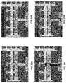
- FIGS. 1A-1Cillustrates one example of an air-matrix DMF apparatus.
- FIG. 1 Ashows an example of an air-matrix DMF apparatus 100 .
- the air-matrix DMF apparatusincludes a plurality of unit cells 191 that are adjacent to each other and defined by having a single actuation electrode 106 opposite from a ground electrode 102 ; each unit cell may any appropriate shape, but may generally have the same approximate surface area.
- the unit cellsare rectangular.
- the dropletse.g., reaction droplets
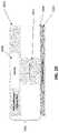
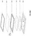
- FIG. 1Bis an enlarged view of a section through a thermal zone of the air-matrix DMF shown in FIG. 1A , showing layers of the DMF device (e.g., layers forming the bottom plate).
- the DMF devicee.g., bottom plate
- the DMF deviceincludes several layers, which may include layers formed on printed circuit board (PCB) material; these layers may include protective covering layers, insulating layers, and/or support layers (e.g., glass layer, ground electrode layer, hydrophobic layer; hydrophobic layer, dielectric layer, actuation electrode layer, PCB, thermal control layer, etc.).
- PCBprinted circuit board
- air-matrix DMF apparatuses described hereinalso include both sample and reagent reservoirs, as well as a mechanism for replenishing reagents.
- a top plate 101in this case a glass material (although plastic/polymeric materials, including PCB, may be used) provides support and protects the layers beneath from outside particulates as well as providing some amount of insulation for the reaction occurring within the DMF device.
- the top platemay therefore confine/sandwich a droplet between the plates, which may strengthen the electrical field when compared to an open air-matrix DMF apparatus (without a plate).
- the upper plate(first plate in this example) may include the ground electrode and may be transparent or translucent; for example, the substrate of the first plate may be formed of glass and/or clear plastic.
- ground electrode layer 102may be coated with a conductive material and/or may include a ground electrode adjacent to and beneath the substrate for the DMF circuitry (ground electrode layer 102 ).
- the ground electrodeis a continuous coating; alternatively multiple, e.g., adjacent, ground electrodes may be used.
- Beneath the grounding electrode layeris a hydrophobic layer 103 .
- the hydrophobic layer 103acts to reduce the wetting of the surfaces and aids with maintaining the reaction droplet in one cohesive unit.
- the second plateshown as a lower or bottom plate 151 in FIGS. 1A-1C , may include the actuation electrodes defining the unit cells.
- the outermost layer facing the air gap 104 between the platesalso includes a hydrophobic layer 103 .
- the material forming the hydrophobic layermay be the same on both plates, or it may be a different hydrophobic material.
- the air gap 104provides the space in which the reaction droplet is initially contained within a sample reservoir and moved for running the reaction step or steps as well as for maintaining various reagents for the various reaction steps.
- Adjacent to the hydrophobic layer 103 on the second plateis a dielectric layer 105 that may increase the capacitance between droplets and electrodes.
- actuation electrodes layer 106Adjacent to and beneath the dielectric layer 105 is a PCB layer containing actuation electrodes (actuation electrodes layer 106 ).
- the actuation electrodesmay form each unit cell.
- the actuation electrodesmay be energized to move the droplets within the DMF device to different regions so that various reaction steps may be carried out under different conditions (e.g., temperature, combining with different reagents, magnetic regions, pump inlet regions, etc.).
- a support substrate 107e.g., PCB
- the actuation electrode layer 106to provide support and electrical connection for these components, including the actuation electrodes, traces connecting them (which may be insulated), and/or additional control elements, including the thermal regulator 155 (shown as a TEC), temperature sensors, optical sensor(s), magnets, pumps, etc.
- One or more controllers 195 for controlling operation of the actuation electrodes and/or controlling the application of replenishing droplets to reaction dropletsmay be connected but separate from the first 153 and second plates 151 , or it may be formed on and/or supported by the second plate. In FIGS. 1A-1C the first plate is shown as a top plate and the second plate is a bottom plate; this orientation may be reversed.
- a source or reservoir 197 of solvent (replenishing fluid)is also shown connected to an aperture in the second plate by tubing 198 .
- the air gap 104provides the space where the reaction steps may occur, providing areas where reagents may be held and may be treated, e.g., by mixing, heating/cooling, combining with reagents (enzymes, labels, etc.).
- the air gap 104includes a sample reservoir 110 and a series of reagent reservoirs 111 .
- the sample reservoirmay further include a sample loading feature for introducing the initial reaction droplet into the DMF device. Sample loading may be loaded from above, from below, or from the side and may be unique based on the needs of the reaction being performed.
- the sample DMF device shown in FIG. 1Aincludes six sample reagent reservoirs where each includes an opening or port for introducing each reagent into the respective reservoirs.
- the number of reagent reservoirsmay be variable depending on the reaction being performed.
- the sample reservoir 110 and the reagent reservoirs 111are in fluid communication through a reaction zone.
- the reaction zone 112is in electrical communication with actuation electrode layer 106 where the actuation electrode layer 106 site beneath the reaction zone 112 .
- the actuation electrodes 106are depicted in FIG. 1A as a grid or unit cells. In other examples, the actuation electrodes may be in an entirely different pattern or arrangement based on the needs of the reaction.
- the actuation electrodesare configured to move droplets from one region to another region or regions of the DMF device. The motion and to some degree the shape of the droplets may be controlled by switching the voltage of the actuation electrodes. One or more droplets may be moved along the path of actuation electrodes by sequentially energizing and de-energizing the electrodes in a controlled manner. In the example of the DMF apparatus shown, a hundred actuation electrodes (forming approximately a hundred unit cells) are connected with the seven reservoirs (one sample and six reagent reservoirs). Actuation electrodes may be fabricated from any appropriate conductive material, such as copper, nickel, gold, or a combination thereof.
- the DMF apparatusis typically integrated so that the electrodes (e.g., actuation electrodes and ground electrode(s)) are part of the same structure that may be loaded with sample and/or fluid.
- the electrodemay be part of a cartridge, which may be removable.
- DMFdigital microfluidic
- air matrix DMF apparatusesalso referred to herein as air gap DMF apparatuses
- these methods and apparatusmay be configured for use in other DMF apparatuses (e.g., oil gap, etc.).
- the methods and apparatuses described hereinmay be used to handle relatively larger volumes that have been possible with traditional DMF apparatuses, in part because the separation between the plates forming the air gap of the DMF apparatus may be larger (e.g., greater than 280 micrometers, 300 micrometers or more, 350 micrometers or more, 400 micrometers or more, 500 micrometers or more, 700 micrometers or more, 1 mm or more, etc.).
- any of the apparatuses and methods described hereinmay be configured to include a disposable cartridge that has the dielectric layer forming the bottom of the cartridge; the driving electrodes do not have to be a part of the cartridge; theses apparatuses may be adapted to allow the dielectric to be securely held to the electrodes during operation, which has proven very challenging, particularly when the dielectric layer is slightly flexible.
- any of the methods and apparatuses described hereinmay include a cartridge in which the ground electrode is included as part of the cartridge.
- the ground electrodemay be formed into a grid pattern forming a plurality of cells.
- the grid patternmay result in clear windows allowing visualization through the ground electrode even when a non-transparent ground electrode (e.g., an opaque or translucent material, such as a metallic coating including, for example, a silver conductive ink) is used to form the ground electrode.
- the grid patternmay mirror the arrangement of the driving electrodes in the DMF apparatus onto which the cartridge may be placed. For example, the grid pattern cover the spaces between adjacent electrodes when the ground electrode is adjacent to the drive electrodes across the air gap.
- the ground electrodemay be formed of a material that is transparent or sufficiently transparent so that it may be imaged through.
- the ground electrodeis a conductive coating.
- the ground electrodemay electrically continuous (e.g., electrically contiguous) but may include one or more openings, e.g., through which a droplet within the air gap may be visualized.
- the upper plate of the cartridgemay be transparent or sufficiently transparent to be visualized through, at least in one or more regions.
- a cartridge for a digital microfluidics (DMF) apparatusmay have a bottom and a top, and may include: a sheet of dielectric material having a first side and a second side, the first side forming an exposed bottom surface on the bottom of the cartridge, wherein at least the second side of the sheet of dielectric material comprises a first hydrophobic surface; a top plate having first side and a second side; a ground electrode on first side of the top plate.
- the ground electrodemay comprise a grid pattern forming a plurality of open cells.
- the cartridgemay also include a second hydrophobic surface on the first side of the top plate covering the ground electrode; and an air gap separating the first hydrophobic layer and the second hydrophobic layer, wherein the air gap comprises a separation of greater than 280 micrometers.
- the top platemay include a plurality of cavities within the thickness of the top plate; these cavities may be closed (e.g., sealed) and/or filled with a thermally insulating material having a low thermal mass and low thermal conductivity.
- the insulating materialcomprises air.
- the cavitiesmay be positioned over the air gap regions that will correspond to heating and/or cooling regions (e.g., thermally controlled regions); the lower thermal mass in these regions may allow for significantly more rapid heating/cooling of a droplet in the air gap under the cavity/cavities.
- the thickness of the top plate in these regionsmay therefore include the cavity; the cavity bottom (corresponding to the bottom surface of the top plate) may be less than 1 mm thick (e.g., less than 0.9 mm, 0.8 mm, 0.7 mm, 0.6 mm, 0.5 mm, 0.4 mm, 0.3 mm, 0.2 mm, 0.1 mm, 90 microns, 80 microns, 70 microns, 60 microns, 50 microns, 40 microns, 30 microns, etc.).
- the cavity bottommay preferably be as thin as possible while providing structural support for the electrode and any dielectric coating on the bottom surface of the top plate.
- the cavity upper surfacemay be substantially thicker (e.g., 1.5 ⁇ , 2 ⁇ , 3 ⁇ , 4 ⁇ , 5 ⁇ , etc.) than the cavity bottom surface.
- the dielectric material forming the bottom surfacemay be made hydrophobic (e.g., by coating, including dip-coating, etc., impregnating with a hydrophobic material, etc.) and/or it may itself be hydrophobic.
- the bottom surfacee.g., the bottom surface of a cartridge
- the bottom surfacemay be formed of a film that is both a dielectric and a hydrophobic material.
- the bottom surfacemay be a Teflon film (which may include an adhesive or an adhesive portion, such as a Teflon tape) that is both hydrophobic and acts as a dielectric.
- Other filmsmay include plastic paraffin films (e.g., “Parafilm” such as PARAFILM M).
- filmssuch as Teflon films
- filmsthat are able to withstand a high temperature (e.g., 100 degrees C. and above) are preferred.
- a cartridge for a digital microfluidics (DMF) apparatusmay generally include a bottom and a top, and may include: a sheet of dielectric material having a first side and a second side, the first side forming an exposed bottom surface on the bottom of the cartridge; a first hydrophobic layer on the second side of the sheet of dielectric material; a top plate having first side and a second side; a ground electrode on first side of the top plate, wherein the ground electrode comprises a grid pattern forming a plurality of open cells; a second hydrophobic layer on the first side of the top plate covering the ground electrode; and an air gap separating the first hydrophobic layer and the second hydrophobic layer, wherein the air gap comprises a separation of greater than 280 micrometers (e.g., greater than 300 micrometers, greater than 400 micrometers, etc.).
- the term “cartridge”may refer to a container forming the air gap, and may be inserted into a DMF reading/driving apparatus.
- the cartridgemay be disposable (e.g., single use or limited use).
- the cartridgemay be configured to allow visualization of fluid (droplets) in the air gap.
- the grid patternmay be particularly useful to allow visualization while still providing the appropriate ground reference to the driving electrode(s).
- the entire gridmay be electrically coupled to form single return (ground) electrode, or multiple ground electrodes may be positioned (via separate and/or adjacent grids) on the top plate.
- the grid pattern of the ground electrodesis formed of a non-transparent material.
- gridmay refer to a pattern of repeating open cells (“windows”) of any appropriate shape and size, in which the border forming the open cells are formed by an integrated (and electrically continuous) material, such as a conductive ink, metal coating, etc.
- a grid as used hereinis not limited to a network of lines that cross each other to form a series of squares or rectangles; the grid pattern may be formed by forming openings into an otherwise continuous plane of conductive material forming the ground electrode.
- the grid pattern of the ground electrodesmay be formed of a conductive ink.
- the grid pattern of the ground electrodesmay be formed of silver nanoparticles.
- the grid patternmay be printed, screened, sprayed, or otherwise layered onto the top plate.
- the borders between the open cells forming the grid patternmay have a minimum width.
- the minimum width of the grid pattern between the open cellsmay 50 micrometers or greater (e.g., 0.1 mm or greater, 0.2 mm or greater, 0.3 mm or greater, 0.4 mm or greater, 0.5 mm or greater, 0.6 mm or greater, 0.7 mm or greater, 0.8 mm or greater, 0.9 mm or greater, 1 mm or greater, etc.).
- the open cells (e.g., “windows”) formed by the grid patternmay be any shape, including quadrilateral shapes (e.g., square, rectangular, etc.) or elliptical shapes (e.g., oval, circular, etc.) and/or other shapes (+ shapes, H-shapes, etc.).
- the grid pattern of the ground electrodemay extend over the majority of the top plate (and/or the majority of the cartridge).
- the grid pattern of the ground electrodemay extend over 50% or more of the first side of the top plate (e.g., 55% or more, 60% or more, 65% or more, 70% or more, 80% or more, 90% or more, etc.).
- the sheet of dielectric materialmay be flexible. This flexibility may be helpful for securing the dielectric to the drive electrodes to ensure complete contact between the dielectric and the drive electrode(s).
- the sheet of dielectric materialmay be sufficiently compliant so that it may bend or flex under a relatively low force (e.g., 50 kPa of pressure or more).
- the sheet of dielectricmay be any appropriate thickness; for example, the sheet may be less than 30 microns thick (e.g., less than 20 microns thick, etc.).
- any of these apparatusesmay include a microfluidics channel formed in the second side of the top plate, wherein the microfluidics channel extends along the second side of the top plate and at least one opening between the microfluidics channel and the air gap.
- the top platemay be formed of any appropriate material, including in particular, clear or transparent materials, (e.g., an acrylic, etc.).
- a cartridge for a digital microfluidics (DMF) apparatusmay include: a flexible sheet of dielectric material having a first side and a second side, the first side forming an exposed bottom surface on the bottom of the cartridge; a first hydrophobic layer on the second side of the sheet of dielectric material; a top plate having first side and a second side; a ground electrode on first side of the top plate, wherein the ground electrode comprises a grid pattern formed of a non-transparent material forming a plurality of open cells along the first side of the top plate; a second hydrophobic layer on the first side of the top plate covering the ground electrode; and an air gap separating the first hydrophobic layer and the second hydrophobic layer, wherein the air gap comprises a separation of greater than 280 micrometers (e.g., 300 micrometers or more, 400 micrometers or more, etc.).
- the cartridgehas a bottom and a top.
- microfluidics channelsare integrated into the DMF components, including in particular the top plate of the DMF apparatus.
- Applicantshave found that integrating one or more microfluidics channels into the top plate may permit the cartridge to be more compact, as well as allow a higher degree of control and manipulation of processes within the air gap that are otherwise being controlled by the electrowetting of the DMF system.
- a cartridge for a digital microfluidics (DMF) apparatusmay include: a sheet of dielectric material having a first side and a second side, the first side forming an exposed bottom surface on the bottom of the cartridge; a first hydrophobic layer on the second side of the sheet of dielectric material; a top plate having first side and a second side; a ground electrode on first side of the top plate; a second hydrophobic layer on the first side of the top plate covering the ground electrode; an air gap separating the first hydrophobic layer and the second hydrophobic layer; a microfluidics channel formed in the second side of the top plate, wherein the microfluidics channel extends along the second side of the top plate; an opening between the microfluidics channel and the air gap; and a cover covering the microfluidics channel, wherein the cover includes one or more access ports for accessing the microfluidics channel.
- the sheet of dielectric materialmay be flexible, and may form the bottom-most surface of the cartridge.
- the sheetmay generally be flat (planar) through it may be flexible.
- the outer surfacemay be protected with a removable (e.g., peel-off) cover.
- the dielectric propertiesmay be those generally consistent with a DMF (and particularly an air-matrix DMF) apparatus.
- the dielectricmay be coated on the inner (second) side with the first hydrophobic layer.
- the hydrophobic layermay be a coating of a hydrophobic material that is relatively inert (e.g., non-reactive with the aqueous droplets that are moved in the air gap).
- the top platemay be planar and may be coextensive (or larger) than the bottom dielectric material.
- the top platemay be any appropriate thickness, and in particular, may be sufficiently thick so that the microfluidic channel may be carved into the second side of the top plate.
- the ground electrodemay be formed on all or some of the first side of the top plate, as mentioned above, and a second hydrophobic layer may be coated over the ground electrode and/or top plate (particularly where open windows through the ground plate expose the top plate). In any of these examples, the thickness of the electrode coating may be minimal, so that the electrodes may be considered flush with the top plate bottom (first) side of the top plate.
- the air gap separating the first hydrophobic layer and the second hydrophobic layermay be relatively large, compared to traditional DMF air-gap systems (e.g., >280, 400 micrometers or more, 500 micrometers or more, 1 mm or more, etc.).
- the microfluidics channel formed in the second side of the top platetypically extends through the top plate along the second side of the top plate and an access opening between the microfluidics channel and the air gap may be formed between the microfluidics channel and the air gap, into the top plate.
- Any of the apparatuses described hereinmay also include a cover covering the microfluidics channel.
- the covermay be formed of any appropriate material, including acrylic.
- the covermay include one or more ports or openings into the microfluidics channel and/or into the air gap.
- the microfluidics channelmay be configured to contain any appropriate amount of fluid, which may be useful for mixing, adding, removing or otherwise interacting with droplets in the air gap.
- the microfluidics channelmay be configured to hold 0.2 milliliters or more of fluid (e.g., 0.3 ml or more, 0.4 ml or more, 0.5 ml or more, 0.6 ml or more, 0.7 ml or more, 0.8 ml or more 0.9 ml or more, 1 ml or more of fluid, 1.5 ml or more, 2 ml or more, 3 ml or more, 4 ml or more, 5 ml or more, 6 ml or more, 7 ml or more, 8 ml or more, 9 ml or more, 10 ml or more, etc.) within the microfluidics channel.
- the microfluidics channelmay connect to one or more reservoirs (e.g., waste reservoir, storage reservoir, etc.) and/or may connect
- the microfluidics channelmay comprise a first microfluidics channel and the opening between the microfluidics channel and the air gap may comprise a first opening;
- the apparatusmay further include a second microfluidics channel formed in the second side of the top plate, wherein the second microfluidics channel extends along the second side of the top plate, and a second opening between the second microfluidics channel and the air gap, wherein the first and second openings are adjacent to each other.
- the first and second openingsmay be a minimum distance apart, which may allow the formation of a “bridging droplet” in the air gap having a minimum size.
- the first and second openingsmay be within about 2 cm of each other on the surface of the top plate (e.g., within about 1 cm or each other, within about 9 mm or each other, within about 8 mm of each other, within about 7 mm of each other, within about 6 mm of each other, within about 5 mm of each other, within about 4 mm of each other, within about 3 mm or each other, within about 2 mm of each other, within about 1 mm of each other, etc.).
- the top platee.g., within about 1 cm or each other, within about 9 mm or each other, within about 8 mm of each other, within about 7 mm of each other, within about 6 mm of each other, within about 5 mm of each other, within about 4 mm of each other, within about 3 mm or each other, within about 2 mm of each other, within about 1 mm of each other, etc.
- any of these cartridgemay also include a window from the top of the cartridge to the air gap through which the air gap is visible. This may allow imaging into the air gap. This imaging may be used to detect output (e.g., reaction outputs, such as binding, colorimetric assays, RT-PCR, etc.).
- the windowmay be any appropriate size; for example, the window may form between 2 and 50% of the top of the cartridge.
- the windowmay be on one side of the cartridge and/or at one end of the cartridge. Multiple imaging windows may be used.
- the bottom of the cartridgeis formed by the first side of the sheet of dielectric material.
- the top of the cartridgemay include a plurality of openings into the air gap.
- the cartridgemay include one or more reagent reservoirs on the second side of the top plate.
- the cartridgein either a reservoir or within the air gap, may include one or more reagents, including in particular lyophilized (e.g., “freeze dried”) reagents.
- the cartridgemay include one or more freeze-dried reagent reservoirs on the second side of the top plate.
- a cartridge (having a bottom and a top) for a digital microfluidics (DMF) apparatusmay include: a sheet of dielectric material having a first side and a second side, the first side forming an exposed bottom surface on the bottom of the cartridge; a first hydrophobic layer on the second side of the sheet of dielectric material; a top plate having first side and a second side; a ground electrode on first side of the top plate; a second hydrophobic layer on the first side of the top plate covering the ground electrode; an air gap separating the first hydrophobic layer and the second hydrophobic layer, wherein the air gap comprises a separation of greater than 500 micrometers; a first microfluidics channel and a second microfluidics channel, wherein the first and second microfluidics channels are formed in the second side of the top plate, wherein the first and second microfluidics channels extend along the second side of the top plate; a first opening between the first microfluidics channel and the air gap and a second opening
- the DMF reader apparatusesmay be configured to apply a vacuum across the dielectric bottom surface of a cartridge so that the electrodes are in uniformly intimate contact with the dielectric forming each of the unit cells form moving a droplet of fluid within the air gap.
- the applicanthave surprisingly found that simply adhesively securing the dielectric material to the electrodes is not sufficient, as it result in un-equal contact and variations in the power required to move droplets as well as inefficiencies in droplet movement, control and consistency.
- the use of vacuum, even in combination with an adhesivehas similar problems, particularly when the dielectric is flexible.
- Described hereinare apparatuses and methods of using them in which a vacuum is used to secure the dielectric bottom of a cartridge through a plurality of openings within the drive electrodes themselves, or surrounding/immediately adjacent to the drive electrodes.
- the vacuumis applied through all or the some of the drive electrodes (e.g., spaced in a pattern on the seating surface, e.g., at the corners)
- the dielectricis consistently held onto the drive electrodes in a uniform manner, even when using a relatively low negative pressure for the vacuum.
- This configurationmay also allow the formation of partitions or barriers within the cartridge by including protrusions on the cartridge-holding surface (onto which the cartridge is held)
- DMFdigital microfluidics
- a DMF reader deviceconfigured to operate with a disposable cartridge having a bottom dielectric surface, a top plate with a ground electrode, and an air gap between the bottom dielectric and the top plate, the device comprising: a seating surface for seating the disposable cartridge; a plurality of drive electrodes on the seating surface, wherein each drive electrode comprises an opening therethrough; a vacuum pump for applying a vacuum to the vacuum ports; and a control for applying energy to sequentially activate and de-activate one or more selected drive electrodes to move a droplet within the air gap of the cartridge along a desired path within the air gap, wherein the DMF reader is configured to apply the vacuum to the vacuum manifold to secure each drive electrode to the bottom dielectric of the disposable cartridge when the disposable cartridge is placed on the seating surface.
- DMFdigital microfluidics
- the apparatusincludes a vacuum manifold that couples the vacuum pump to a plurality of vacuum ports for applying a vacuum.
- the DMF reader devices described hereinmay be configured to operate with any of the cartridges described herein, and may be adapted for use with such cartridges. However, it should be understood that the cartridge is not a necessary part of the DMF reader apparatus. In general, these apparatuses may operate with a cartridge (e.g., a reusable or disposable cartridge) that has a bottom dielectric surface, a top plate with a ground electrode, and a gap (e.g., typically but not necessarily an air gap) between the bottom dielectric and the top plate.
- a cartridgee.g., a reusable or disposable cartridge
- a gape.g., typically but not necessarily an air gap
- the DMF apparatusmay also generally include a seating surface for seating the disposable cartridge.
- the seating surfacemay include the drive electrodes, which may be flush or substantially flush with the seating surface, and/or any protrusions that may be used to form a partition within the gap region (e.g., air gap) of the cartridge by predictably deforming the dielectric into the gap region.
- the plurality of drive electrodes on the seating surfacemay be formed on the seating surface or milled into the seating surface.
- the seating surfacemay be a substrate such as a printed circuit board (e.g., an electrically insulating surface), onto which the drive electrodes are attached or formed.
- all or a majority of the drive electrodes in the electrode arraymay include an opening that passes through the drive electrode and connects to the vacuum source.
- the vacuum sourcemay be a vacuum manifold that connects these openings through the drive electrodes to a source of vacuum, such as a vacuum pump that is part of the apparatus, or a separate vacuum pump that is connected (e.g., wall vacuum) to the apparatus.
- the openings through the electrodesmay be the same sizes, and they may be located anywhere on/through the drive electrodes.
- the openingsmay be any shape (e.g., round, oval, square, etc.). In some variations the size of the openings may be about 1 mm in diameter (e.g., 1.2 mm diameter, 1.1 mm diameter, 1.0 mm diameter, 0.9 mm diameter, 0.8 mm dieter, etc.).
- the vacuum manifoldmay be coupled to and/or may include a plurality of vacuum ports that each couple to one (or in some variations, more than one) of the openings in the drive electrodes.
- the vacuum manifoldmay be located beneath the seating surface.
- a vacuum manifoldmay be tubing or other channels beneath the seating surface that connects to the openings in the drive electrodes.
- the DMF apparatuses described hereintypically include a controller for coordinating and driving the electrodes.
- This controllermay include one or more processors, memory, and any other circuitry necessary or useful for operating the device, including coordinating the application of energy to activate/inactivate the drive electrodes, the pump(s) for vacuum and/or microfluidic control, one or more valves (e.g., for microfluidic control, vacuum control), temperature control (e.g., resistive heater, Peltier cooling, etc.) the motor(s) (e.g., for driving opening and closing the device door, the optics, etc.), one or more displays, etc.
- any of these devicesmay include one or more projections extending from the seating surface, wherein the one or more projections are configured to form partitions in the air of the cartridge when the vacuum is applied through the openings in the drive electrodes.
- any of these apparatusesmay include an optical reader configured to detect an optical signal from a cartridge seated on the seating surface.
- the optical readermay be movable or fixed.
- the optical readermay be used to detect (e.g., sense) a feed or change due to one or more interactions (e.g., binding, enzymatic reactions, etc.) in the droplet.
- the optical readercan be configured to detect an optical signal from a cartridge seated on the seating surface.
- the optical sensor(s)may provide a detection of a readout from the apparatus.
- Any of these devicemay include one or more motors, e.g., configured to move the optical reader.
- the apparatusmay also include one or more temperature sensors (e.g., thermistors, etc.).
- the devicemay include one or more temperature sensors coupled to the seating surface.
- the thermistormay project from the seating surface and form a barrier or chamber within the air gap of the cartridge.
- the one or more temperature sensorsmay be within the substrate of the seating surface and in thermal contact with the seating surface, e.g., via a thermally conductive material, such as copper.
- the devices described hereinmay include one or more heaters, including in particular resistive heaters.
- the devicemay include a resistive heater underlying (or overlying) at least some of the drive electrodes; this may allow for temperature-regulated sub-regions of the apparatus.
- the entire driving electrode surfacemay also be cooled (e.g., by circulation of a cooling fluid) to slightly below room temperature (e.g., between 15 degrees C. and 25 degrees C., between 15 degrees C. and 22 degrees C., between 15 degrees C. and 20 degrees C., between 15 degrees C. and 18 degrees C., etc.).
- the apparatusmay also include one or more magnets above or underneath one or more of the drive electrodes configured to be activated to apply a magnetic field.
- magnetic beadsmay be used for binding material or other reactions within the DMF apparatus, and the magnetic beads may be selectively held within one or more regions of the device.
- one or more neodymium magnetsmay be used, e.g., by moving the magnet closer or farther from the cartridge to hold magnetic particles in position (e.g., moving it up towards the electrodes by 3 mm, 4 mm, 5 mm, 6 mm, 7 mm, 8 mm, etc.).
- An electromagnetmay be selectively activated or deactivated to hold/release magnetic particles.
- any of the apparatuses described hereinmay also include one or more Peltier coolers underlying at least some of the drive electrodes configured to cool to 10 degrees C. or less (e.g., 5 degrees C. or less, 7 degrees C. or less, 11 degrees C. or less, 12 degrees C. or less, 15 degrees C. or less, 20 degrees C. or less, etc.).
- 10 degrees C. or lesse.g., 5 degrees C. or less, 7 degrees C. or less, 11 degrees C. or less, 12 degrees C. or less, 15 degrees C. or less, 20 degrees C. or less, etc.
- any of these DMF reader apparatusesmay also include one or more cartridge trays into which the cartridge may be loaded, so that it can automatically be moved into position within the apparatus.
- any of these apparatusesmay include a cartridge tray for holding a cartridge in a predetermined orientation (which may be fixed by the shape of the cartridge and the receiving tray being complementary); the cartridge tray may be configured to move the disposable cartridge onto the seating surface. Once on the seating surface, the vacuum may be applied to lock it into position.
- connectionsmay be made from the top of the cartridge to one or more microfluidics ports, e.g., for applying positive and/or negative pressure (e.g., vacuum) to drive fluid within a microfluidic channel on the top of the cartridge and/or into/out of the gap (e.g., air gap) region within the cartridge.
- positive and/or negative pressuree.g., vacuum
- any of these devicesmay include an outer housing, a front panel display, and one or more inputs (such as a touchscreen display, dial, button, slider, etc.), and/or a power switch.
- the apparatusmay be configured to be stackable, and/or may be configured to operate in conjunction with a one or more other DMF apparatuses.
- a single housingmay enclose multiple cartridge seating surfaces, each having a separately addressable/controllable (by a single or multiple controllers) drive electrode arrays, allowing parallel processing of multiple cartridges; in these variations, all of some of the components (pumps, motors, optical sub-systems, controller(s), etc.) may be shared between the different cartridge seating surfaces.
- Any of these devicesmay include an output configured to output signals detected by the device.
- the outputmay be on one or more displays/screens, and/or they may be electronic outputs transmitted to a memory or remote processor for storage/processing and/or display.
- any of these apparatusesmay include a wireless output.
- any of the DMF apparatuses described hereinmay also include one or more microfluidic vacuum ports positioned above the seating surface and configured to engage with an access ports for accessing a microfluidics channel of the cartridge when the cartridge is seated on the seating surface.
- a digital microfluidics (DMF) reader deviceconfigured to operate with a disposable cartridge having a bottom dielectric surface, a top plate with a ground electrode, and an air gap between the bottom dielectric and the top plate, may include: a seating surface for seating the disposable cartridge; a plurality of drive electrodes on the seating surface, wherein each drive electrode comprises an opening therethrough; a plurality of vacuum ports, wherein each vacuum port is coupled to one or more of the openings in the drive electrodes; a vacuum pump for applying a vacuum to the vacuum ports; one or more projections extending from the seating surface; and a control for applying energy to sequentially activate and de-activate one or more selected drive electrodes to move a droplet within the air gap of the cartridge along a desired path within the air gap, wherein the DMF reader is configured to apply the vacuum to the vacuum ports to secure each drive electrode to the bottom dielectric of the disposable cartridge so that the one or more projections partition the air gap when the disposable cartridge is placed on the seating surface.
- DMFdigital microfluidic
- methods of preventing droplet evaporation within an air-matrix digital microfluidic (DMF) apparatuscomprising: introducing an aqueous reaction droplet into an air gap of the air-matrix DMF apparatus which is formed between a first plate and a second plate of the air-matrix DMF apparatus; sequentially energizing driving electrodes on or in the first plate to move the aqueous reaction droplet within the air gap of the air-matrix DMF apparatus so that it combines with a droplet of nonpolar fluid within the air gap of the air-matrix DMF apparatus, forming a coated reaction droplet in which that the nonpolar fluid coats the aqueous reaction droplet and protects the reaction droplet from evaporation; and sequentially energizing the driving electrodes to move the coated reaction droplet within the air gap of the air-matrix DMF apparatus.
- DMFdigital microfluidic
- the volume of the nonpolar fluidmay be less than the volume of the aqueous reaction droplet.
- Any of these methodsmay include combining, within the air gap of the air-matrix DMF apparatus, the coated droplet with one or more additional aqueous droplets. Any of these methods may also include removing the coating of nonpolar fluid by at least partially withdrawing the coated droplet out of the air gap of the air-matrix DMF apparatus into a microfluidic channel. The method may also include adding the droplet of nonpolar fluid into the air gap of the air-matrix DMF apparatus through an opening in the first or second plate. Generally, the droplet of nonpolar fluid may be liquid at between 10 degrees C. and 100 degrees C.
- a method of preventing droplet evaporation within an air-matrix digital microfluidic (DMF) apparatusmay include: introducing an aqueous reaction droplet into an air gap of the air-matrix DMF apparatus which is formed between a first plate and a second plate of the air-matrix DMF apparatus; sequentially energizing driving electrodes on or in the first plate to move the aqueous reaction droplet within the air gap of the air-matrix DMF apparatus so that it combines with a droplet of nonpolar fluid within the air gap of the air-matrix DMF apparatus (although in some variations the nonpolar fluid may be combined with a sample prior to being loaded into the air gap), forming a coated reaction droplet in which that the nonpolar fluid coats the aqueous reaction droplet and protects the reaction droplet from evaporation, wherein the nonpolar fluid is liquid at between 10 degrees C.
- the volume of the nonpolar fluidis less than the volume of the aqueous reaction droplet; and sequentially energizing the driving electrodes to move the coated reaction droplet within the air gap of the air-matrix DMF apparatus.
- the volume of the nonpolar liquidmay be less than the droplet volume, the volume of nonpolar liquid jacketing the droplet may be larger than the volume (up to about 3 ⁇ the volume) of the droplet.
- the methods and apparatuses described hereinmay be particularly well suited for the use with large-volume droplets and processing.
- most unit droplets of DMF apparatuses, and particularly air-matrix DMF apparatusesare limited to about 4 microliters or less of aqueous fluid, and the air gap is limited to less than about 250 or 300 micrometers separation between the driving electrodes and the ground electrode (top and bottom plates of the air gap region).
- Described hereinare methods of operating on larger volumes, in which the separation between the drive electrodes (e.g., bottom plate) and the ground electrodes (e.g., top plate) may be much larger (e.g., between about 280 micrometers and 3 mm, between about 300 micrometers and 3 mm, between about 400 micrometers and 1.5 mm, e.g., between 400 micrometers and 1.2 mm, etc., or 400 micrometers or more, 500 micrometers or more, 1 mm or more, etc.).
- the separation between the drive electrodes (e.g., bottom plate) and the ground electrodes (e.g., top plate)may be much larger (e.g., between about 280 micrometers and 3 mm, between about 300 micrometers and 3 mm, between about 400 micrometers and 1.5 mm, e.g., between 400 micrometers and 1.2 mm, etc., or 400 micrometers or more, 500 micrometers or more, 1 mm or more, etc.).
- the unit droplet size(the droplet on a single unit cell driven by a single drive electrode may be much larger, e.g., 5 microliters or more, 6 microliters or more, 7 microliters or more, 8 microliters or more, 9 microliters or more, 10 microliters or more, 11 microliters or more, 12 microliters or more, 13 microliters or more, 14 microliters or more, 15 microliters or more, etc., e.g., between 5-20 microliters, between 5-15 microliters, between 7 and 20 microliters, between 7 and 15 microliters, etc.).
- Dispensing large droplets using electrowettingis routinely done with smaller volume (e.g., less than 5 microliters), however, dispensing larger volumes as a single unit has proven difficult, particularly with a high degree of accuracy and precision. Described herein are methods of dispensing a predetermined volume of liquid using electrowetting.
- a predetermined volume of fluid into an air gap of an air-matrix digital microfluidics (DMF) apparatuswherein the air gap is greater than 280 micrometers (e.g., 300 micrometers or more, 400 micrometers or more, etc.) wide
- the DMF apparatuscomprises a plurality of driving electrodes adjacent to the air gap
- the methodcomprising: flooding a portion of the air gap with the fluid from a port in communication with the air gap; applying energy to activate a first driving electrode adjacent to the portion of the air gap that is flooded; and applying suction to withdraw the fluid back into the port while the first electrode is activated, leaving a droplet of the fluid in the air gap adjacent to the activated first electrode.
- Applying energy to activate the first driving electrodemay include applying energy to activate one or more driving electrodes that are contiguous with the first driving electrode, and further wherein applying suction to withdraw the fluid back into the port while the first driving electrode is activated comprises withdrawing the fluid while the first driving electrode and the one or more driving electrodes that are contiguous with the first driving electrode are active, leaving a droplet of the fluid in the air gap adjacent to the activated first driving electrode and the one or more driving electrodes that are contiguous with the first driving electrode.
- the first driving electrodemay be separated from the port by a spacing of at least one driving electrode. Any of these methods may further comprise inactivating one or more driving electrodes adjacent a second portion of the air gap that is within the flooded portion of the air gap, and that is between the port and the first driving electrode.
- the air gapmay be greater than 500 micrometers.
- Flooding the portion of the air gapmay comprises applying positive pressure to expel fluid from the port.
- the methodmay further comprising sequentially energizing driving electrodes adjacent to the air gap to move the droplet within the air gap of the air-matrix DMF apparatus.
- Applying suction to withdraw the fluid back into the port while the first electrode is activatedmay comprise leaving a droplet of the fluid having a volume that is 10 microliters or greater in the air gap adjacent to the activated first electrode.
- a method of dispensing a predetermined volume of fluid into an air gap of an air-matrix digital microfluidics (DMF) apparatuswherein the air gap is greater than 280 micrometers wide (e.g., 300 micrometers or more, 400 micrometers or more, etc.) further wherein the DMF apparatus comprises a plurality of driving electrodes adjacent to the air gap, may include: flooding a portion of the air gap with the fluid from a port in communication with the air gap; applying energy to activate a first driving electrode or a first group of contiguous driving electrodes adjacent to the portion of the air gap that is flooded, wherein the first driving electrode or the first group of contiguous driving electrodes are spaced apart from the port by one or more driving electrodes that are not activated; and applying suction to withdraw the fluid back into the port while the first electrode or first group of contiguous electrodes are activated, leaving a droplet of the fluid in the air gap adjacent to the first electrode or first group of contiguous electrodes.
- DMFdigital microflu
- control systems for DMF apparatusessuch as those described herein.
- control systemsincluding graphical user interfaces for operating any of these apparatuses.
- These control systemsmay include software, hardware and/or firmware.
- any of these apparatusesmay be configured as instructions stored in a non-transient medium (e.g., memory) for performing any of them methods and procedures described herein.
- a digital microfluidics (DMF) apparatuscomprising: providing a graphical user interface comprising a menu of fluid handling control commands, including one or more of: move, heat, remove, cycle, wait, breakoff, mix and dispense; receiving a fluid handling protocol comprising user-selected fluid handling control commands; calculating a path for moving fluid within an air gap of the DMF apparatus based on the fluid handling protocol, wherein the path minimizes the amount of overlap in the path to avoid contamination; and executing the fluid handling protocol using the DMF apparatus based on the calculated path.
- DMFdigital microfluidics
- the fluid handling control commandsmay include at least one of: move, heat, remove, wait, and mix.
- the fluid handling commandsmay include all: move, heat, remove, wait, and mix.
- a usermay select icons corresponding to each of these commands, and may enter them in an order and/or may indicate incubation timing and temperature conditions.
- the apparatusmay automatically determine the optimal path within the air-gap region of the cartridge in order to perform each of these steps (e.g., by moving the droplet(s) to the appropriate region of the cartridge including the heater, magnets, microfluidic ports, etc., so that the droplet(s) may be manipulated as required.
- receiving the fluid handling protocolmay comprise receiving a string of fluid handling control commands.
- Calculating the pathmay comprise calculating the path based on the arrangement of heating and cooling zones in the DMF apparatus. Calculating the path may comprise determining the shortest path that does not cross over itself.
- executing the fluid handling protocol on the DMF apparatusmay comprise executing the fluid handling protocol in a disposable cartridge coupled to the DMF apparatus.
- DMF reader devicesconfigured to operate with a removable and/or disposable cartridge having a bottom dielectric surface, a top plate with a ground electrode, and an air gap between the bottom dielectric and the top plate, the device comprising: a seating surface for seating the disposable cartridge on an upper surface; a first plurality of drive electrodes on the seating surface, wherein all or some of the drive electrodes comprises an opening therethrough; a thermal control for applying thermal energy to a first region of the seating surface; a plurality of thermal vias, wherein the thermal vias comprise a thermally conductive material and are in thermal communication with the first region of the seating surface but are electrically isolated from the subset of electrodes and further wherein the thermal vias are in thermal communication with the thermal control; a plurality of vacuum ports, wherein each vacuum port is coupled to one or more of the openings through the drive electrodes; a vacuum pump for applying a vacuum to the vacuum ports; and a control for applying energy to sequentially activate and de-activate one or more
- each thermal viamay have a diameter of between about 0.5 and about 2 mm (e.g., between about 0.5 mm and about 1.8 mm, between about 0.5 mm and about 1.5 mm, between about 0.5 mm and 1.2 mm, between about 0.8 mm and 1.2 mm, etc.). Any number of thermal vias may be used per cell (e.g., there may be between about 5-15 thermal vias associated with a region corresponding to a single electrode in the first region).
- the thermal viasmay each be filled with a thermally conductive material; the material may be electrically conductive or electrically insulative. In some variations the thermally conductive material is a metal.
- the readermay further include one or more resistive heaters underlying at least some of the drive electrodes.
- the seating surfacemay be formed or at least partially formed on a printed circuit board (PCB), including on an array of electrodes formed on the PCB.
- PCBprinted circuit board
- any of the readers described hereinmay include one or more magnets; in some variations the magnet(s) may be underneath one or more of the drive electrodes configured to be activated to apply a magnetic field. For example, the magnetic field may pass through an opening in the drive electrode.
- the readermay include one or Peltier coolers underlying at least some of the drive electrodes configured to cool to less than 10 degrees C.
- the materialmay include a droplet (e.g., aqueous droplet) a wax, a droplet coated/ensheathed in a wax (e.g., liquid wax), an oil droplet, a droplet with magnetic particles, etc.
- the identitymay be determined for a material at a specific location in the air gap, e.g., between the upper and lower surfaces forming the air gap in the cartridge.
- the cartridgemay be divided up into cells (e.g., regions above individual drive electrodes.
- a method of detecting the location and/or identitymay include: disconnecting a reference electrode on a first side of the air gap of the DMF cartridge from a driving circuit; setting the voltage of one or more drive electrodes of an array of drive electrodes on a second side of the air gap to a high voltage while setting all other drive electrode of the array of drive electrodes to ground; sensing the voltage at the reference electrode; determining a capacitance between the first side of the air gap and the second side of the air gap based on the voltage sensed at the reference electrode; and identifying the material in the air gap adjacent to the one or more drive electrodes based on the determined capacitance.
- the methodmay also include reconnecting the reference electrode to the driving circuit, and driving a droplet within the air gap by applying a voltage between the reference electrode and one the drive electrodes. These steps may be repeated iteratively, to track movement of material in the air gap.
- Disconnecting the reference electrodemay comprise allowing the reference electrode to float (e.g., not ground).
- the reference electrodemay be the entire upper electrode (on the first side of the air gap, opposite from the array of drive electrodes).
- Disconnecting the reference electrode from the drive circuitrymay include connecting the reference electrode to sensing circuitry for detecting the voltage at the reference electrode and therefore the capacitance of the air gap.
- the reference circuitrymay include on or more reference capacitors arranged to allow measurement of the air gap capacitance.
- Setting the voltage of the one or more of drive electrodes to a high voltagemay comprises setting the one or more of the drive electrodes to between 10 and 400V (e.g., between 100V and 500V, e.g., about 300V, etc.).
- any of these methodsmay include determining a total capacitance for the air gap by setting the voltage of all of the drive electrodes of the array of drive electrodes to the high voltage while the reference electrode is disconnected from the driving circuit and sensing the voltage a the reference electrode to determine the total capacitance.
- the methodmay further include determining the total capacitance using one or more reference capacitors connected to the reference electrode when the reference electrode is disconnected from the driving circuit. For example, determining the capacitance between the first side of the air gap and the second side of the air gap based on the voltage sensed at the reference electrode may further comprise using the total capacitance.
- Identifying the material in the air gapmay comprise using a reference database comprising a plurality of ranges of capacitance to identify the material in the air gap based on the determined capacitance.
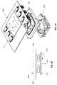
- any of the cartridge described hereinmay include: a sheet of dielectric material having a first side and a second side, the first side forming an exposed bottom surface on the bottom of the cartridge, wherein at least the second side of the sheet of dielectric material comprises a first hydrophobic surface; a tensioning frame holding the sheet of dielectric material in tension so that it is substantially flat; a top plate having a first side and a second side and a thickness therebetween; a ground electrode on the first side of the top plate; a second hydrophobic surface on the first side of the top plate covering the ground electrode; and an air gap separating the first hydrophobic layer and the second hydrophobic layer, wherein the air gap comprises a separation of greater than 280 micrometers.
- Any of the other cartridge features described hereinmay be included with these cartridges.
- any of these cartridgesmay also include a lip extending at least partially (including completely) around, and proud of, the sheet of dielectric material. This lip may engage with a channel or trough on the seating surface.
- the cartridgemay include a peripheral channel or trough into which a projection on the seating surface of the reader engages.
- the tensioning framemay include an outer frame and an inner frame.
- the sheetmay be held between the outer and inner frames.
- These cartridgesmay include any of the other cartridge features mentioned herein.
- FIG. 1Ais a schematic of one example of an air-matrix digital microfluidic (DMF) apparatus, from a top perspective view.
- DMFdigital microfluidic
- FIG. 1Bshows an enlarged view through a section through a portion of the air-matrix DMF apparatus shown in FIG. 1A , taken through a thermally regulated region (thermal zone).
- FIG. 1Cshows an enlarged view through a second section of a region of the air-matrix DMF apparatus of FIG. 1A ; this region includes an aperture through the bottom plate and an actuation electrode, and is configured so that a replenishing droplet may be delivered into the air gap of the air-matrix DMF apparatus from the aperture (which connects to the reservoir of solvent, in this example shown as an attached syringe).
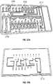
- FIG. 2is an example of a DMF surface using a rigid cartridge including the electrodes and an air-gap region, similar to that shown in FIGS. 1A-1C .
- FIG. 3Ashows an example of a typical DMF arrangement, e.g., using a rigid cartridge
- FIG. 3Bshows an example of a DMF configuration in which the cartridge 315 is a disposable portion that does not include the electrodes but that is held onto the reusable electrodes by a plurality of localized vacuum ports (adjacent to or passing through the electrodes).
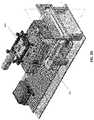
- FIG. 3Cis an example of a DMF apparatus configured as a compact driver/reader that is configured to work with a removable/disposable cartridge.
- the DMF apparatusincludes an array of electrodes (e.g., greater than 500 different electrodes), and multiple independent regions for heating/cooling (thermal cycling, etc.) controlling magnetic beads, pumping microfluidic channels, automatic seating and sealing of the cartridge, as well as optical viewing/management.
- FIG. 3Dis another example of a DMF apparatus as described herein configured as compact driver/reader that may include greater than 900 (e.g., greater than 920 different electrodes), independent heaters for isothermal regions and thermal cyclers, magnetic zones that can be independently engaged/disengaged, pumps and valves for operating microfluidics in the disposable cartridge (in addition to the DMF control via the plurality of electrodes), a vacuum manifold coordinated with the plurality of electrodes (e.g., having ports that pass through the electrodes to seal and secure the dielectric to the electrodes for accurate and reliable DMF control, multiple independent qPCR zones, multiple optical channels, and a draw-mechanism for inserting/removing the cartridge allowing access from both above and below the apparatus.
- the apparatus show in FIGS. 3C and 3Dmay provide liquid cooling of ambient and heating zones.
- FIG. 3Eis another example of the apparatus shown in FIGS. 3C-3D , showing an exemplary arrangement of the pumps (e.g., vacuum pumps to secure the cartridge, a liquid cooler and compressor, one or more motors for actuating the drawer that receives the cartridge and for actuating the optics, a control for opening/closing the drawer, a manifold for operating any microfluidics on the cartridge (in addition to or instead of the DMF), and an electrode array for driving DMF in the cartridge.
- the pumpse.g., vacuum pumps to secure the cartridge, a liquid cooler and compressor, one or more motors for actuating the drawer that receives the cartridge and for actuating the optics, a control for opening/closing the drawer, a manifold for operating any microfluidics on the cartridge (in addition to or instead of the DMF), and an electrode array for driving DMF in the cartridge.
- the pumpse.g., vacuum pumps to secure the cartridge, a liquid cooler and compressor, one or more motors
- FIG. 3Fis an example of the outer housing of an exemplary DMF apparatus such as the one shown in FIGS. 3C-3E , configured as a single tray (cartridge) apparatus.
- the trayis shown extended.
- the dimensionsshow are for illustrative purposes only, and may be larger or smaller by, e.g., +/ ⁇ 5% (e.g., 10%, 15%, 20%, 25%, 30%, 35%, 40%, 50%, 75%, 100%, etc.).
- FIGS. 3G and 3Hshow an example of the front ( FIG. 3G ) and back ( FIG. 3H ) sides of the exemplary DMF apparatus of FIG. 3F .
- the tray for loading/unloading the cartridgeis shown closed.
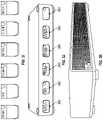
- FIG. 3Iillustrates another example of an exemplary DMF apparatus configured to process a plurality of cartridges.
- FIG. 3Iis a front view of an apparatus is configured to process six cartridges, and includes six access controls and display panels, which may be color coded.
- componentssuch as the pumps, motor(s), optics, controllers, etc. may be shared, and/or multiple separate components (e.g., electrode arrays, sub-controllers, etc.) may be used.
- the housingmay be configured to allow stacking of a plurality of apparatuses.
- FIG. 3Jis a front perspective view of the apparatus of FIG. 3I .
- FIG. 3Killustrates an example of a back view of the multiplexed apparatus of FIGS. 3I-3J .
- FIG. 3Lis an enlarged view of the far left cartridge drawer, including a cartridge-specific display, input (e.g., button, touchscreen, etc.), and the cartridge drawer.
- inpute.g., button, touchscreen, etc.
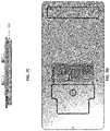
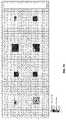
- FIG. 4Ashows a top view of the electrodes (e.g., electrode array) formed as part of the apparatus.
- the electrodesmay include a plurality of vacuum openings through them, as shown.
- the electrodesmay define different regions, including thermally controlled regions (e.g., regions having a thermistor and/or cooling and/or heating.
- thermally controlled regionse.g., regions having a thermistor and/or cooling and/or heating.
- 18 rows and 10 columnsare shown; larger or smaller arrays may be used.
- FIG. 4Bshows an enlarged region of the electrodes, forming the upper electrode layer, showing the vacuum openings through most (e.g., >50%, 55%, 60%, 65%, 70%, 75%, 80%, 85%, 90%, 95%, etc.) or all of the electrodes.
- square electrodesare shown (with centered vacuum openings), other electrode shapes, e.g., interlocking, rectangular, circular, etc., or vacuum opening locations (off-centered, etc.) through the electrodes may be used.
- a temperature sensore.g., thermistor
- FIG. 4Cillustrates a resistive heating layer that may be present beneath the electrode layer (such as is shown in FIG. 4B ).
- One continuous, or multiple separate, trace(s) of resistive materialmay be used beneath the array.
- the black dotsindicate the vacuum manifold (forming the plurality of vacuum openings through the electrodes.
- the resistive heating layermay be electrically isolated from the electrodes above them; the current applied through the resistive heating layer may be regionally controlled, by a controller.
- the controllermay include PID control.
- FIG. 5Ashows a partially dis-assembled view of the apparatus, showing connections that may be made between the electrode-containing PCB, a liquid coolant, and the vacuum for securing the cartridge dielectric onto the electrodes.
- FIG. 5Bshows an example of a fan and heatsink, reservoir and pump that may be used for the liquid coolant of the cartridge-contacting surface(s), including the electrodes.
- the pump, tubing, fan, heatsink and reservoirmay be used to move water or liquid coolant below the electrodes so that the coolant can absorb the heat while passing below the electrodes, where it may then be re-circulated after being cooled again while passing through the fan and heatsink.
- FIG. 5Cshows another view of a PCB with the electrodes similar to that shown in FIGS. 4A-4C , connected to a vacuum pump as well as the liquid coolant (input and output).
- FIGS. 5D and 5Eillustrate the application of vacuum to secure a cartridge (shown here as a proof of concept by just the dielectric material.
- the vacuumis off, and the dielectric is not secured against the electrodes.
- the dielectricmay wrinkle, and may include regions of poor contact, including poor electrical contact.
- FIG. 5Eshows the dielectric held against the electrodes by a plurality of openings through the electrodes, which holds the dielectric uniformly against the electrodes, and results in surprisingly uniform electrical properties between the removable cartridge and the electrodes.
- FIG. 5Fshows an example of a top view of a PCB showing a small electrode array with holes formed through the central region of each electrode.
- FIG. 5Gshows a portion of the PCB of FIG. 5F below the electrodes (over which the other layers may be formed), showing the holes through the PCB forming that may be connected to the vacuum pump.
- FIG. 6illustrates the different functional regions that maybe formed by the electrode array and/or removable cartridge.
- the removable cartridgehas been made transparent (a microfluidics region above the top plate, air-gap and dielectric forming the DMF portion of the cartridge has been made transparent).
- the different regionsare indicated by different boxes, and may be distributed in a particular arrangement over the array.
- seven of the electrodesare configured as magnetic regions 605 , which can apply a local (to that electrode) magnetic force to retain a magnetic bead or particle within a droplet on the electrode.
- Eight of the peripheral regions(each spanning six electrodes) are configured as cooling zones, which may be in thermal contact with a Peltier device or other thermal cooling region.
- FIG. 6illustrates the different functional regions that maybe formed by the electrode array and/or removable cartridge.
- the removable cartridgehas been made transparent (a microfluidics region above the top plate, air-gap and dielectric forming the DMF portion of the cartridge has been made transparent).
- the different regionsare indicated by
- six 16-electrode regions on the left sideare configured as cooling zones which may also be in thermal contact with the same or different Peltier device (e.g., holding them below 10 deg. C.).
- Two central heating zones(one spanning five electrodes, the other spanning 32 electrodes) are also included, and may be thermally cycled over the entire zone or over regions of the zone(s).
- Four optically read zones(each spanning four electrodes) are spaced apart from each other on the right side perimeter of the device.
- the heating and/or thermally cycling regionsare centrally located, apart from the peripheral cooling/storage regions. There may be overlap between the zones, such as the magnetic zones and the heating/cooling zones.
- FIG. 6also shows, in a transparent view, a microfluidics portion that may be formed above (and in the top plate, as described) the air gap.
- the microfluidics portion 611includes a pair of serpentine microfluidics channels 615 , 616 that each connect to an opening (which may be regulated by a valve) into the air gap.
- the microfluidics portionmay also include valves.
- the microfluidics channelalso includes a pair of ports 617 , 618 through which positive and/or negative pressure may be applied to modulate (along with any valves) the movement of fluid in the microfluidics region and (in some variations) into or out of the air gap.
- the microfluidics portionmay also include one or more waste chambers 621 ,
- FIG. 7Ais a top view of an exemplary cartridge as described herein.
- the cartridgeincludes a DMF portion, including a top plate and dielectric, separated by an air gap, and a microfluidics portion that connects into the air gap, and may externally connect to a channel input and/or output. Fluid may be applied into the cartridge through one or more openings into the air gap (shown as small openings) and/or through the channel input/outputs.
- the right side of the cartridgeincludes a window region, allowing optical viewing through the cartridge.
- FIG. 7Bshows a top perspective view of the cartridge of FIG. 7A .
- FIG. 7Cis an end or side view from the left side of the cartridge of FIGS. 7A and 7B , showing the upper microfluidics channels and the lower DMF portion (showing the spacing between the top, ground, plate and the dielectric, forming the air gap.
- FIG. 7Dis a top view of the cartridge of FIGS. 7A-7C , with the cover for the microfluidics channels removed, showing the channels.
- FIG. 8Ais an example of a disposable cartridge, including a plastic top plate and a dielectric.
- FIG. 8Bshows paper digital microfluidics that may be used as part of a cartridge.
- FIG. 9Ashows an example of an open array of electrodes under a disposable plastic top plate and a dielectric.
- FIG. 9Bshows a cartridge over the open array, held in place by a vacuum to keep it rigidly attached over the electrodes.
- FIG. 9Cillustrates the use of openings through the electrode array; these openings may be used to apply suction (e.g., vacuum) sufficient to hold the cartridge (e.g., the bottom, dielectric layer) aligned and secured to the apparatus. Positive pressure may be applied to release the cartridge.
- suctione.g., vacuum
- Positive pressuremay be applied to release the cartridge.
- FIG. 10Aschematically illustrates an example of a patterned ground electrode on a top plate as described herein.
- FIG. 10Bshows a side view of the patterned top plate shown in FIG. 8A .
- FIGS. 11A and 11Bshow front and side views, respectively, of another variation of a top plate including a ground electrode formed of a non-transparent conductive ink (e.g., silver conductive ink, carbon conductive ink, etc.), formed in a grid pattern including a plurality of window openings forming the grid.
- a non-transparent conductive inke.g., silver conductive ink, carbon conductive ink, etc.
- FIG. 12Ais an example of conductive ink applied to form the ground electrode on a top plate.
- FIG. 12Bshows an example of a patterned top plate ground electrode (including a plurality of openings there through).
- FIGS. 13A and 13Billustrate example of patterned ground electrodes (top plates) on a flexible, transparent substrate.
- FIGS. 14A-14Cillustrate operation of a DMF apparatus using a patterned ground electrode.
- FIGS. 15A-15Cillustrate one example of a microfluidics channel interfacing with a DMF air gap region as described herein.
- the microfluidics portion of a cartridgeis shown as a pair of channels each connected to an inlet/outlet, and each ending in a bridging region forming an opening into the air gap of the DMF portion of the cartridge (in this example, below the microfluidics portion). Fluid may be removed, added, washed, etc. into/out of the air gap of the DMF portion.
- FIGS. 15B and 15Cfluid washed through the bridging droplet and into the air gap by alternating and applying suction between the inlet/outlet, as shown.
- external fluidic componentse.g., tubing and reservoirs
- the microfluidics channelsmay be used for adding/removing reagent (e.g., removing waste, washing, etc.).
- the bridging dropletmay be an electrode or group of electrodes and the size of the droplet may be regulated by DMF.
- FIG. 16Ashows one example of a section through a top plate to form a microfluidics channel immediately adjacent to the DMF portion (e.g., above or below the DMF portion, as part of the top plate).
- FIG. 16Bshows an example of a top plate into which microfluidic channels have been formed.
- FIG. 16Cis another example of a top plate of a DMF apparatus configured as a microfluidics channel.
- the top plateis shown as an acrylic material into which channels and holes have been formed (e.g., by milling, cutting, rastering, etc.).
- FIG. 16Dshows another example of a microfluidics channel formed into a top plate of a DMF portion of a cartridge.
- FIGS. 17A and 17Billustrate extraction and mixing of fluid in a DMF apparatus (e.g., cartridge) as described herein, using a fluid application and extraction technique that includes a bifurcated channel, allowing a large volume of fluid to be exchanged between two reservoirs.
- a DMF apparatuse.g., cartridge
- FIGS. 17A and 17Billustrate extraction and mixing of fluid in a DMF apparatus (e.g., cartridge) as described herein, using a fluid application and extraction technique that includes a bifurcated channel, allowing a large volume of fluid to be exchanged between two reservoirs.
- the fluid application and extraction deviceis connected through the top plate.
- FIG. 17Bthe fluid application and extraction device is connected from the side plate.
- FIG. 17Cis another example of a DMF cartridge configured for mixing, extraction, adding, etc. fluid with one or more droplets in the air gap of the DMF cartridge.
- the interface 1127 for the fluid lineswhich may be microfluidic channels, including microfluidic channels formed in part by the top plate 1117 , interfaces through the top plate, and (unlike FIG. 17A ) the air gap in this interface region may be larger than the air gap in other portions of the DMF cartridge.
- the interface 1127 for the fluid line(s)is at the edge of the air gap, similar to FIG. 17B ; in FIG. 17D , the air gap region is larger than in other regions of the cartridge. In any of the FIGS.
- the fluid lines (e.g., 1143 , 1145 ) and reservoirs ( 1105 , 1107 )may form part of the DMF apparatus, and may interface with a port on the cartridge, e.g., the top surface of the cartridge, and/or one or more valves.
- FIGS. 18A-18Cillustrate operation of a fluid application and extraction device similar to the one shown in FIG. 17A .
- FIGS. 19A-19Cillustrates the effect of evaporation on a droplet over 2 minutes in an air-gap DMF apparatus held at 95 degrees C., showing substantial evaporation.
- FIGS. 20A-20Cshow the resistance to evaporation when using a jacketing of nonpolar material (e.g., liquid paraffin) after one hour ( FIG. 20B ) and two hours ( FIG. 20C ), showing little or no evaporation.
- nonpolar materiale.g., liquid paraffin
- FIGS. 21A-21Dillustrate the use of a non-polar jacketing material in an air-matrix DMF apparatus.
- FIGS. 21A-21Bshow the movement of the aqueous (polar) droplet while coated with a non-polar jacketing material that is moved along with the droplet.
- FIGS. 21C-21Dillustrate adding additional polar material to the droplet, which expands to include the additional polar material.
- FIG. 21E-21Iillustrate adding a large sample to a jacketing material, and mixing the sample.
- FIGS. 22A-22Dillustrate the control of droplet volume when dispensing droplets (e.g., reagents) into an air-gap of a DMF apparatus.
- the air-gaps described hereinmay be large air-gaps (e.g., greater than 280 micrometers, greater than 300 micrometers, >400 micrometers, >500 micrometers, >600 micrometers, etc. separation between the top and bottom dielectrics).
- the electrowetting forces alonemay not be sufficient to dispense droplets of a predetermined volume.
- droplet break off from a large volumemay be used to dispense a predetermined volume.
- FIG. 22A-22Ddroplet break off from a large volume may be used to dispense a predetermined volume.
- a dispensing electrodeis activated, spaced from the dispensing port (tube).
- the reagent to be dispensedis applied into the air gap, flooding the region including the dispensing electrode that is separated from the dispensing port by at least one electrode.
- the reagentis then sucked back into the dispensing port, while the dispensing electrode(s) is/are active, but the electrode(s) between the dispensing port and the dispensing electrode(s) is/are not active, forming a neck, which (as shown in FIG. 22D ) eventually breaks off, leaving the droplet of a predetermined volume on the dispensing electrode(s).
- FIGS. 23A-23Fillustrate example of dispensing droplets of predefined volumes using the technique described in FIGS. 22A-22D , above.
- FIG. 24shows an example of a method of controlling a DMF apparatus as described herein, including programming the apparatus using a graphical user interface.
- FIG. 25Aillustrates an example of visual controls or commands ( FIG. 25A ) and a protocol describes using these visual controls/commands ( FIG. 25B ).
- FIGS. 26A-26Hillustrate an example of a user interface for controlling a DMF apparatus as described herein.
- FIGS. 27A and 27Billustrate top and bottom perspective views, respectively of one example of a top portion of digital microfluidics cartridge as described herein.
- FIG. 28illustrates an example of a portion of a cartridge showing a thermally controlled region.
- FIG. 29is an example of a portion of a reader (e.g., cartridge seat portion) having a reduced thermal mass to enhance the rate of temperature regulation of cartridge held on the seat portion.
- a readere.g., cartridge seat portion
- FIG. 30is another example of a portion of a reader (e.g., cartridge seat portion) having a reduced thermal mass to enhance the rate of temperature regulation of cartridge held on the seat portion.
- a readere.g., cartridge seat portion
- FIGS. 31A and 31Billustrate examples of readers include thermal vias for helping control the temperature of a cartridge (e.g., of one or more cells of an air gap of a cartridge).
- FIG. 32is an example of a cartridge including an opening in the top plate for sampling or adding fluid to a droplet in the cartridge.
- FIG. 33Ashows an ITO sensing circuit with a switch.
- FIG. 33Billustrates another example of a capacitive sensing circuit that includes multiple reference capacitors.
- FIGS. 34A-34Cillustrate one method of identifying and/or locating a droplet in the air gap as described herein.
- FIG. 34Ashows one example of a range of capacitances corresponding to the peresences or absence of various materials (e.g., aqueous droplet, wax, etc.) in the air gap at a particular cell.
- FIG. 34Bis a graph showing exemplary voltge measurments from the sensing electrode (top electrode).
- FIG. 34Cis is a graph showing an example of the change in electrical permittivity of water as a function of temperature.
- FIG. 35Ais a top view of one example of a vacuum chuck.
- FIG. 35Bis a cross sectional view of the vacuum chuck of FIG. 35A .
- FIG. 36shows an isometric view of the chuck shown in FIGS. 35A-35B .
- FIG. 37shows a top view of a chuck similar to the one shown in FIGS. 35A-35B .
- FIG. 38Ashows another example of a vacuum chuck.
- FIG. 38Bshows a cross sectional and zoomed-in view of this chuck.
- FIG. 39shows a bottom view of a chuck similar to that shown in FIGS. 35A-35B .
- FIG. 40shows an isometric view of a chuck similar to that shown in FIG. 35A .
- FIG. 41Ashows one example of a heat dissipation system that may be included in any of the reader devices described herein.
- FIG. 41Bis a sectional view through the chuck of FIG. 41A .
- FIG. 42shows a front view of a chuck and a fan.
- FIG. 43shows an example of an arrangement of a chuck, a fan and a PCB (part of a seating surface).
- FIG. 44is a perspective view of a chuck that may include a thermal (e.g., heat) dissipation system for regulating temperature of a cartridge.
- a thermal (e.g., heat) dissipation systemfor regulating temperature of a cartridge.
- FIG. 45Ais a top view of the chuck of FIG. 44 .
- FIG. 45Bis a sectional view through the chuck of FIG. 45A .
- FIG. 46shows a side view of an assembly of a chuck, a heat sink and a pair of cooling fans, with arrows indicating the flow of temperature (cooling the chuck and therefore the cartridge when loaded onto the apparatus).
- FIGS. 47A-47Cillustrate the assembly of a vacuum chuck and cooling sub-system (e.g., heat sink block and cooling fans).
- a vacuum chuck and cooling sub-systeme.g., heat sink block and cooling fans.
- FIG. 48illustrates one example of an assembly for a reader including a PCB with an array of electrodes for applying DMF to a cartridge (not shown), a vacuum block for holding the cartridge bottom onto the PCB and a thermal regulator sub-system including a heat sink/heat block and a pair of cooling fans.
- FIGS. 49A and 49Billustrate a tensioning frame and a film frame, respectively, for securing and holding smooth a film (e.g., dielectric film) that may form the bottom of a cartridge.
- a filme.g., dielectric film
- FIG. 49Cis a side view of an assembled tensioning frame.
- FIG. 49Dis a perspective view of an assembled tensioning frame.
- FIG. 50Ais an example of an exploded view of a cartridge.
- FIG. 50Bis another example of an exploded view of a cartridge.
- FIG. 51is an exploded view of an example of a cartridge and a cartridge seating portion of a reader.
- FIG. 52Ais a top view of a PCB of a reader to which a cartridge may be seated on.
- FIG. 52Bis a side view of the PCB portion shown in FIG. 52A
- FIG. 52Cis an example of a side view of a cartridge shown on a seating surface of a reader.
- FIG. 52Dis an enlarged view from FIG. 52C .
- FIG. 53is an exploded view of a cartridge and seating surface/region of a reader.
- FIG. 54Ais a top view of a PCB (that may form the seating surface) of a reader.
- FIG. 54Bis a side sectional view through the portion of the reader shown in FIG. 54A .
- FIG. 55shows an example of an electrode grid setup with independent action zones.
- FIG. 56schematically shows four independently controlled 1-plex modules with a console unit that may operate all of them.
- a DMF apparatusmay include a compact DMF driver/reader that is configured to work with a removable/disposable cartridge.
- the DMF driver/readermay include an array of drive electrodes that are adapted to align and secure a cartridge in position by applying negative and/or positive pressure at multiple points, and specifically at the electrode-contact points, on the cartridge.
- the cartridgemay include an air gap that is open to the environment (e.g., to the air) via openings such as side (lateral) openings and/or top openings.
- the air gapmay be formed between two dielectric layers.
- An upper, top, regionmay include one or more ground electrodes.
- the ground electrodemay be advantageously formed of a non-transparent material that is patterned to include one or more windows that allow imaging through the top. These windows may be arranged over the electrode, so that the ground region extends opposite the drive electrodes and around and/or between the drive electrodes.
- any of the apparatuses described hereinmay also include a fluid application and extraction component (e.g., a fluid application and/or extraction device) that is connected through the top, or through the side of the cartridge, into the air gap.
- a fluid application and extraction componente.g., a fluid application and/or extraction device
- Any of the apparatuses described hereinmay include or use a non-polar jacketing material (e.g., a non-polar liquid such as a room temperature wax) that forms a protective jacket around the aqueous droplet(s) in the apparatus, and may be moved with the droplet.
- user interfaces for interacting with the apparatusincluding user interfaces for controlling the apparatus to move, mix, combine, wash, magnetically concentrate, heat, cool, etc. These user interfaces may allow manual, automatic or semi-automatic entering, control and/or execution of a protocol.
- FIG. 2illustrates an example of a DMF apparatus that is similar to the one shown in FIGS. 1A-1C .
- the DMF apparatusincludes a plurality of drive electrodes 201 (which are shaped into non-square/non-rectangular shapes and positioned adjacent to each other in rows or lines.
- four reservoir regions 203 , 205 , 207 , 209are positioned on the right side, and may be preloaded or otherwise hold droplets of materials to be added during operation of the DMF apparatus. Some or all of the electrodes may be heated or cooled.
- the DMF driving electrodes 211are solid, planar electrodes.
- the application of energy between the driving electrodes and the ground or reference electroderesult in movement of an aqueous (e.g. polar) droplet.
- the ground or reference electrodeis formed as a conductive, transparent coating (e.g., ITO) on the upper plate, which is also clear (transparent). This allows the device to be monitored, including monitoring any of the cells, e.g., unit cells, from above the air matrix/air gap.
- FIGS. 3A and 3Bshow the different configurations of a DMF system that includes integrated drive electrodes ( FIG. 3A ) and a system in which the drive electrodes are part of the reader, but the cartridge includes only the ground electrodes (e.g., top plate), air gap and the dielectric bottom.
- the air gapis formed between the grounded top plate 303 , and the drive electrodes and dielectric film 305 (e.g., a Teflon film).
- the drive electrodes and dielectric filmmay be part of a cartridge that includes the top plate, and may be separately attached onto the substrate (switch board 307 ) that connects to a main processor 309 and a power supply board 311 .
- the cartridgedoes not include the drive electrodes 313 , but instead includes the top plate/ground electrode, dielectric and an air gap between them 315 .
- a vacuume.g., vacuum manifold
- pressuree.g., between 50 kPa and 250 kPa, 50 kPa or greater, 60 kPa or greater, 70 kPa or greater, 80 kPa or greater, 90 kPa or greater, 100 kPa or greater, 110 kPa or greater, etc.
- the electrodesmay be supported on a substrate, such as a printed circuit board or switch board 317 , which may also be connected to the main processor 319 and power supply 321 .
- the dielectric filmmay also be hydrophobic (e.g., a Teflon film may be used) or may be treated, coated, sprayed, dipped into, etc., a hydrophobic material to make at least the side facing the air-gap hydrophobic.
- FIG. 3Cis an example of a compact DMF driver/reader that may be used with any of the cartridges described herein.
- dimensionsare exemplary only, but show the compact nature of the reader.
- the readermay include a cartridge seating surface 351 , beneath which the vacuum, heating, cooling, magnetic and other components, including control circuitry may be positioned.
- microfluidics control componentse.g., valves, pumps, etc.
- FIG. 3Dillustrate another example of a DMF reader apparatus including integrated drive electrodes on part of the seating surface.
- a drawer(not shown) may be used to insert/remove the cartridge and seat it onto the seating surface, where a vacuum may be used to secure the cartridge in position and make complete electrical contact between the drive electrodes and the dielectric of the cartridge.
- Both the microfluidics handing portion 355 and the optics(e.g., optical reader) may be positioned above the seating surface.
- FIG. 3Eshows another perspective view of the apparatus of FIGS. 3C and 3D , showing the drawer 361 holding an exemplary disposable cartridge 363 .
- the drawermay open/close (e.g., by pushing a control, such as a button 362 ) to pull the cartridge into and out of the apparatus, as shown, and position the cartridge on the seating surface which includes a driving electrode array 365 , in which each of the driving electrodes (in this example, and shown in greater detail below) includes an opening for the application of a vacuum to hold the dielectric onto the driving electrodes.
- a microfluidics valve manifold 367may be included, and may connect to a pump or pump 369 .
- the same, or a separate pump 371may be used to provide the pressure for holding the dielectric onto the seating surface through the electrodes.
- the systemmay also include an optics sub-system 373 for imaging through at least a portion of the cartridge, in order to report-out data about the reaction being performed on the apparatus.
- a motor for driving the optics and/or the drawer opening/closingmay also be included.
- a liquid cooler and compressor 375may be included as well, for circulating a cooling liquid, e.g., under the cartridge.
- FIG. 3Fshows a side perspective view of the apparatus of FIG. 3E with the drawer 361 open and the cover 381 on.
- the housingmay include feet 383 that may engage with receiving sites 385 on the top surface, so that these device may be easily and securely stacked.
- FIGS. 3G and 3Hshow front and rear views, respectively.
- the apparatusmay include a plurality of cartridge-receiving sites (e.g., seating surfaces) for operating in parallel on multiple cartridges.
- FIGS. 3I-3Killustrate an example of an apparatus in which six cartridge receiving drawers can be used to operate on up to six separate cartridges simultaneously.
- each receiving drawermay include a button for opening/closing the drawer, and a separate readout screen 390 may be included.
- FIGS. 3I and 3Jshow front, and front perspective views, respectively, and FIG. 3K is a rear view.
- internal componentssuch as the processor(s) and optical sensor(s) may be shared between the different seating surfaces within each sub-region of the apparatus.
- FIG. 3Lshows a detailed view of one example of a front of the apparatus.
- the seating surface of an exemplary DMF reader deviceis shown in greater detail in FIGS. 4A-4C and FIGS. 9A-9C .
- the seating surfaceincludes an array of driving electrodes 401 (labeled in rows 0-9 and columns A-R). Each of these driving electrodes includes a central hole or opening through the electrode, through which a vacuum can be applied to hold the dielectric of the cartridge against the drive electrodes.
- the seating surfacealso includes temperature sensors (thermistors 405 ) positioned between the electrodes in different orientations.
- FIG. 4Bshows a slightly enlarged view of the seating surface, including the driving electrodes, showing a thermistor 405 between the driving electrodes.
- the vacuum openings 407are more clearly visible in FIG.
- driving electrodesmay be used, including interlocking driving electrodes.
- the pattern of driving electrodesmay be formed that is not monolithic; for example the electrode pattern may include open regions that do not include driving electrodes (e.g., regions surrounding driving electrodes, etc.) as shown in FIGS. 1A and 2 .
- FIG. 4Cshows an example of a heater that may be positioned underneath some of the drive electrodes, such as the sub-set of drive electrodes shown in FIG. 4B .
- resistive heating circuitry 409may underlie the drive electrodes (e.g., embedded at any layer of the PCB forming the seating surface).
- resistive heating and thermistorsmay be embedded at any layer of the electrode PCB board.
- the heatermay be part of the PCB with the electrodes and thermistor, as shown in FIGS. 4A-4C .
- the current, and therefore the temperature of the driving electrodes and/or the adjacent dielectric (and therefore any droplet on the cell under the dielectric/driving electrode)may be regulated, e.g., by a PID control loop, in combination with the thermistor.
- a liquid coolermay be circulated through the substrate, e.g., on the bottom of the seating surface.
- the resistive heateris shown as a continuous trace of low-resistive material (e.g., having a resistance between about 10-15 ohms).
- any appropriate temperature regulating techniquemay be employed.
- stirringe.g., magnetic stirring
- Even a small-volume dropletmay contain a range of local temperatures, so the temperature distribution may have a standard deviation. This can be reduced by stirring, e.g., via magnetic beads. With enough stirring, the droplet may be brought close to isothermal.
- the top platemay be used to help regulate the temperature.
- the top platemay be used for heatsinking.
- a thermal conductore.g., a steel block
- a thermal conductore.g., a steel block
- Differences in temperature between the top plate and a bottom heatermay help determine the temperature standard deviation. Heating the top plate in tandem with the electrode may reduce the time necessary to raise the temperature.
- the top platemay include a local resistive heater, similar to that shown in FIG. 4C .
- the heated/cooled top platemay be achieved separately from the cartridge by including a top thermal mass that engages with the top of the cartridge when it is on the seating surface.
- a heated and/or cooled top thermal massmay be a manifold that is pressed down onto the cartridge.
- a liquid coolantmay be applied to the bottom and/or the top of the cartridge.
- a circulating liquid coolantmay be used.
- the entire bottom of the cartridgemay be cooled (e.g., to within 3-5 degrees of room temperature, e.g., between 15-35 degrees C.).
- FIG. 5Aan example of a seating surface 501 is shown removed from the device to illustrate a liquid coolant coupled to the substrate of the seating surface so that coolant may be pumped into 503 and out of 505 through the seating surface 501 .
- FIG. 5Billustrates a pump 511 , tubing 517 , fan 515 , heatsink 516 and a reservoir 513 are used to move water or liquid coolant below the electrodes.
- the coolantabsorbs the heat while passing below the electrodes and is cooled again while passing through the fan and heatsink.
- FIGS. 5D and 5Eillustrate securing a dielectric (shown unattached to a cartridge, for illustration purposes) onto a seating surface having electrodes with openings through which a vacuum is applied.
- the vacuumis off, and the dielectric 555 is loosely resting on the seating surface, with numerous wrinkles.
- FIG. 5Ethe vacuum is applied through the electrodes.
- the use of a vacuum in this wayallows for a reduced dielectric thickness, and thus lower power (e.g., voltage) requirements.
- the configuration shown in FIGS. 5A-5Eresulted in a reduction of the power requirements for DMF being halved.
- the thickness of the dielectricmay be between 7-13 microns.
- the dielectricis almost twice as thick (e.g., 25 microns).
- a pump 560is shown connected via tubing to a vacuum manifold that is configured to pull air through the holes in the electrodes.
- the dielectric filmsits on top and stays rigid as long as the pump is pulling air.
- any projection in the surface of the dielectricwill not interfere with the seal, but will form enclosures, channels, barriers, or other structures within the air gap, which may help partition the air gap.
- FIGS. 5F and 5Gillustrate the upper and an intermediate layer of the seating surface, showing the connection between the vacuum source (via connector 565 ), though a mechanical and/or tubing manifold ( FIG. 5G ) and out of the openings through the electrodes ( FIG. 5F ).
- FIGS. 9A to 9Cillustrate an example of a seating surface 900 onto which the cartridge may be held by the vacuum ports through the electrodes.
- the seating surfaceis formed on a substrate (e.g., a PCB or other electrically insulated surface), and includes an array of electrode 901 , shown in this example as quadrilateral (e.g., square) shapes. Any other appropriate shape may be used.
- the drive electrodes 901are thin conductive surfaces that may be flush or substantially flush with the seating surface, or may project slightly above the seating surface.
- a cartridge 905is shown placed atop the array of drive electrodes 901 on the seating surface 900 . This cartridge may be placed on the seating surface by a drawer (as shown in FIGS.
- FIG. 9Cshows an enlarged view of a portion of the seating surface 900 , showing electrodes 901 having a central opening 909 into the vacuum manifold.
- the seating surface of the apparatusmay be divided up into functional regions, controlling the location and operation of different portions, including heating, magnetic bead control, washing, adding solution(s), cooling, imaging/detecting, etc. These regions may be defined in the DMF reader apparatus.
- FIG. 6illustrates different functional regions that are defined based on the connections within and/or beneath (or in some variations, above) the seating surface.
- solutionmay be dispensed through the top of the cartridge (e.g., the top plate), via one or more holes.
- the drive electrodes under the secured dielectricmay therefore form a plurality of unit cells (one drive electrode per unit cell), and each cell or region of cells (multiple cells) may be controlled to perform a specified function.
- the DMF apparatusincludes an arrangement of zones or unit cells such as cooling zones (e.g., cooling via underlying Peltier zone) 605 that are arranged around the periphery of the cartridge. These regions may also be used to store solution, and may be held at between 3 degrees C. and 20 degrees C. (e.g., below 10 degrees C., between about 2 degrees C. and 25 degrees).
- the central heating zone(s) 609may be used for heating a droplet.
- One or more magnetic zones 603may be used for turning on/off magnetic fields that may be useful to immobilize a magnetic particle (e.g., for removing a material, etc.). Any of the zones may overlap.
- at least one unit cell in the heating zonemay also be a magnetic zone.
- Other functional zonesinclude imaging/optical zones. In this case, the dual functions may be possible because the magnet may be positioned right under the heating zone when using resistive heating.
- any of these cartridgesmay also include a reagent reservoir in the top plate.
- the microfluidicsmay be controlled by one or more valves (e.g., valve control) for dispensing and mixing and taking to waste.
- a cartridge as described hereinmay include a dielectric, a first hydrophobic coating on the dielectric, a second hydrophobic coating on a ground electrode (and/or top pate) and the top plate onto which the ground electrode is coupled.
- the hydrophobic coatingmay be a Teflon coating, for example.
- the cartridgemay also include one or more microfluidic channels, particularly those formed directly into the top plate with controlled access into the air gap.
- FIGS. 7A-7Dillustrate one example of a cartridge 700 including a microfluidics region 703 on the upper surface, covered by a cover 703 having one or more access ports 705 , 707 for accessing the microfluidics portion of the device.
- the cover 703may also include one or more valves and/or one or more openings 709 that may be used for delivering removing fluid and/or gas (e.g., air).
- the cartridgemay also include openings through the top plate 713 , including openings that connect the microfluidics channel to the air gap region within the channel.
- FIG. 7Bis a top perspective view of the cartridge of FIG. 7A .
- FIG. 7Bshows a side view of the cartridge, showing the lowest bottom dielectric film 751 material.
- the air gapis not visible in FIG. 7C , but may refer to the spacing 753 between the dielectric and the ground electrodes.
- FIG. 7Dshows the top plate with the cover removed. Comparing FIG. 7A to FIG. 7D , with the top removed, both the first and the second microfluidics channels are shown, each with an opening from the microfluidics channel into the air gap.
- FIG. 7Bis a top perspective view of the cartridge of FIG. 7A .
- FIG. 7Bshows a side view of the cartridge, showing the lowest bottom dielectric film 751 material.
- the air gapis not visible in FIG. 7C , but may refer to the spacing 753 between the dielectric and the ground electrodes.
- FIG. 7Dshows the top plate with the cover removed. Comparing FIG. 7A to FIG. 7D , with
- the two channelsmay be simultaneously used by pushing/pulling fluid through one channel into the cell underlying them for rinsing, mixing, removing waste, etc.
- FIGS. 7A-7Dthere are via holes through the top plate in to air.
- the top platemay be thicker, in some variations it may be beneficial to include more reagents, including freeze-dried reagents that may be rehydrated.
- FIGS. 8A-8Billustrate different example of cartridges that may be used.
- an exemplary cartridge 800(similar to that shown in FIGS. 7A-7D ) is shown over a seating surface 803 including electrodes.
- the cartridge 800includes a microfluidics portion 805 formed above the air gap (not visible in FIG. 8A ), on one end of the cartridge.
- the other end of the cartridgeincludes a window region 807 through which a portion of the air gap may be imaged.
- the both the front (window) region and the back (microfluidics) regions of the cartridgemay include access regions for accessing the air gap and/or microfluidics portions.
- FIG. 8Bthree different DMF design configurations on paper are shown. Paper DMF devices were formed by inkjet printing arrays of silver driving electrodes and reservoirs connected to contact pads onto paper substrates.
- the top platemay be any appropriate material, including transparent materials, such as acrylics.
- the top platemay be formed of (or may contain) one or more conductive polymers.
- the ground electrode(s)may be formed on the top plate.
- the ground electrodemay be formed of a conductive material, including in particular, printed conductive materials, such as conductive inks.
- the return electrodemay be, in particular, a pattern (e.g., a grid pattern) having a plurality of window openings forming the grid. The pattern may be selected so that when the cartridge is secured to the seating surface of the reader the window openings align with the drive electrodes.
- the ground electrode 1001is shown, having a grid pattern including a plurality of open, square-shaped windows 1003 .
- the window openings forming the grid patternmay be any appropriate shape, including other quadrilateral shapes (e.g., rectangular, etc.), other polygonal shapes, elliptical (e.g., circular, oval, etc.) shapes, regular and non-regular shapes.
- An additional layersuch as a hydrophobic layer, may overlay both the conductive material pattern and the plate.
- FIG. 10Bshows an exemplary side view (thickness not to scale) showing the plate 1005 and the conductive, patterned electrode 1001 . In general, none of the figures described herein are necessarily show to scale, unless indicated otherwise.
- FIGS. 11A and 11Bshow another example of a ground electrode 1101 formed into a grid pattern, having elliptical 1103 (in this example, circular) window openings, formed onto a first plate 1105 .
- the electrodemay be formed of a conductive ink such as a silver ink, as shown in FIG. 8B .
- a conductive inksuch as a silver ink
- Such printable inksmay have advantages over other conductive materials previously described, such as ITO, despite not being clear.
- the use of silver nanoparticles formed into a gridmay result in lower, more repeatable and more accurate energy requirements.
- the pattern of the electrodehas a minimum thickness of between about 50 and 200 microns (e.g., 100 microns).
- the outline around the open windowsmay be configured to be positioned over the spaces between adjacent electrodes in the drive electrode array.
- the central regions(which in particular, may include openings for applying the vacuum as described above) may be centered in the window. Since many conductive inks (e.g., including silver ink) are not transparent, the open windows may allow visualization of the air gap beneath the ground electrode.
- the minimum thicknessmay be between 50 and 150 microns, in practice, the minimum thickness of the grid pattern may be greater than 100 microns width; for example, the minimum thickness may be between 100 and 200 microns.
- the ground electrodemay be formed onto a substrate (e.g., top plate) in any appropriate manner.
- FIGS. 12A and 12Billustrate two methods of forming the ground electrode.
- the top electrodeis formed by coating the clear substrate with a conductive ink, and allowing the resulting layer to dry.
- a patternsuch as those described above, is formed by a printing technique (e.g., screening, printing, etc.).
- the patternis formed by printing a conductive silver nanoparticle ink in a pattern similar to that shown in FIG. 10A .
- FIGS. 13A and 13Bshow an example of a top plate having a grid patterned ground electrode.
- the grid patternis formed into a second order pattern having regions including reservoirs for storing fluids in the air gap, as well as passages and chambers where different reactions (heating, mixing, cooling, etc.) may be performed.
- FIGS. 14A-14Cillustrate operation of the ground plate of FIG. 13A-13B , showing the drive electrodes driving movement of a droplet using this ground plate configuration in the cartridge.
- a droplet 1403is held in the air gap on a first unit cell.
- the air gapis between a dielectric that is pulled down onto the seating surface and the driving electrodes by a vacuum pulled though the driving electrodes.
- the pattern of the grid forming the ground electrodematches the arrangement of the driving electrodes in the seating surface.
- the drive electrodes 1411each include an opening 1413 connected to a vacuum manifold through which vacuum is applied to hold the dielectric, and therefore the cartridge, in position.
- FIG. 14A and FIG. 14Bpower is applied to the electrode underlying the droplet and to one or more adjacent electrodes in a sequence allowing a change in the electrowetting of the droplet, driving the droplet 1405 to the left, as shown in FIG. 14B ; this process may be repeated, as shown in FIG. 14C , moving the droplet to another unit cell 1407 in the air gap.
- the movement using the grid-patterned ground electrodeis equivalent or better than the movement of a monolithic ground electrode.
- the return electrode(s) on the top plate of the cartridgemay be formed of a material that is layered onto the top plate.
- the electrically conductive layer forming the return electrode eon the top platemay be formed of aluminum and a film of dielectric and/or hydrophobic material.
- the electrode(s)may be formed of ITO, an adhesive and a dielectric and/or hydrophobic film.
- the conductormay be formed of an ITO film (including a primer and Teflon coating).
- any of these apparatuses and methodsmay include one or more microfluidics channel(s) integrated into the cartridge.
- the apparatusmay include a microfluidics mixing and extraction region. This is illustrated in FIGS. 15A-15C .
- two microfluidics channels 1501 , 1503may be formed into the top plate of the air gap, and an opening in to the air gap may be positioned within a fixed distance from each other. Fluid may be passed from one microfluidics channel to another microfluidics channel, through the air gap. The region of the air gap between these openings may bridge these two regions 1505 .
- This configurationmay be used to mix a larger droplet (e.g., greater than 5 microliters, greater than 7 microliters, greater than 10 microliters, greater than 15 microliters, greater than 20 microliters, greater than 25 microliters, greater than 30 microliters, greater than 1 ml, etc.) than could be easily done within the air gap.
- a larger droplete.g., greater than 5 microliters, greater than 7 microliters, greater than 10 microliters, greater than 15 microliters, greater than 20 microliters, greater than 25 microliters, greater than 30 microliters, greater than 1 ml, etc.
- a first pressure source 1507negative pressure and/or positive pressure
- a second pressure source 1509positive and/or negative pressure
- Fluidmay be withdrawn from the air gap through the opening 1505 into the first channel 1501 ; alternatively or additionally, by applying positive pressure 1507 , fluid may be moved from the first channel 1501 into the air gap through the opening 1505 ; concurrently, fluid may be drawn from the air gap at or near the same opening 1505 into the second channel by applying negative pressure 1509 within the second channel.
- Alternating positive and negative pressuremay pass relatively larger volumes of solution between the two microfluidics channels, in and out of the air gap, as shown in FIGS. 15B and 15C .
- the top plateintegrates microfluidic channels, as well as reservoirs and tubing; alternatively or additionally, one or more ports (e.g., for connecting to the pressure source(s), valves, and the like may be included.
- a cover over the microfluidics channelsmay be included with port(s) and/or valves and the like.
- Positive and negative pressuremay be applied within the microfluidics channel(s), for example, by reversing the polarity of a peristaltic pump.
- FIGS. 16A-16Dillustrate examples of microfluidics channels that may be included.
- FIG. 16Aillustrates the formation of a microfluidics channel formed in part by the top plate.
- a portion of the channelmay be formed in the plate (e.g., the acrylic plate) itself, where a second portion of the channel may be formed from another material that has its other side coated with a conductive material (i.e., indium tin oxide, copper, nickel, chromium and gold).
- the layersmay be held together by an adhesive, and/or may be bonded together.
- microfluidic channels in any of the cartridges and apparatuses described hereinmay be formed by laser cutting.
- a raster channelmay be cut into part B (the acrylic forming the top plate), and a hole may be cut in part B.
- one or more pump holesmay be cut into part A.
- a double-sided adhesivee.g., tape
- a rollermay be used to place part A on part B, avoiding air bubbles.
- pipette holesmay be cut out for dispensing reagents, and the bottom may be Teflon (e.g., hydrophobic) coated and the entire assembly baked at between 80-200 degrees (e.g., between 90-18 degrees, etc.).
- the ground electrodemay already be formed onto the plate.
- FIG. 16Billustrates another example of a set of microfluidic channels 1605 , 1607 formed into the top plate.
- a set of reagent inlets 1609are shown as well, providing openings into the air gap region for loading regents.
- reagentsmay be pre-loaded (wet or dry/lyophilized) into the cartridge, including in one or more reservoirs above the top plate or in the top plate, e.g., in a microfluidics channel, and/or directly into the air gap region.
- FIGS. 16C and 16Dillustrate additional examples of microfluidics channels that may be formed into a top plate of a cartridge.
- FIGS. 17A and 17Billustrate schematically examples of a method for applying and removing (including washing) fluid to/from the air gap of a DMF apparatus 1120 .
- the air gap 1121 of the cartridgeis formed between the top plate 1117 and the bottom dielectric 1126 .
- a connector interface 1127connects a combined inlet/outlet port for a first fluid channel 1143 and a second fluid channel 1145 .
- These fluid channelsmay be connected one or more reservoirs 1105 , 1107 .
- two separate connector interfaces (ports)may be used, one connected to each fluid line (e.g., which may be a microfluidics channel, as described above).
- a bridging droplet in the air gap region 1121may connect to both inlet and outlet lines, and fluid may be drawn into and out of the fluid lines 1143 , 1145 to mix the droplet, add fluid to the droplet, remove fluid from the droplet, expose a solid phase capture element (e.g., magnetic bead, non-magnetic bead, etc.) to the same fluid repetitively to deplete the fluid from the analyte of interest, e.g., to concentrate the analyte on the solid phase or other surfaces), etc.
- a solid phase capture elemente.g., magnetic bead, non-magnetic bead, etc.
- the cartridgemay include air gaps of different heights.
- the air gap for the region around the connector interface 1127may be greater (e.g., between 0.5 and 2 mm) larger than the air gap between other regions of the top plate and the dielectric 1121 , as a portion of the top plate 1115 (or a separate top plate 1115 connected to another top plate 1117 ) may be spaced further from the dielectric 1126 .
- the air gap 1119 near the connector interface at the edge of the apparatusmay be larger than the air gap 1121 in other regions, e.g., by spacing a portion of the top plate 1117 further from the dielectric 1126 bottom layer.
- FIGS. 18A-18CA prototype DMF apparatus and cartridge illustrating the principle shown in FIG. 17C is illustrated in FIGS. 18A-18C , and was used to demonstrate the proof of principle for mixing larger volumes of solution in an air gap of a DMF cartridge.
- the upper plate of the DMF cartridgeincluded an opening through the top plate 1801 connected to a first fluid line 1843 and a second fluid line 1845 .
- fluidwas moved back and forth between the first reservoir 1805 and the second reservoir 1807 , as shown in the sequence of FIGS. 18A, 18B and 18C .
- magnetic particles holding an analyte of interestare magnetically held within the air gap (e.g., against the bottom, e.g., hydrophobic coated dielectric) by the DMF apparatus 1809 while the fluid is exchanged between the reservoirs, enhancing binding and/or rinsing.
- FIGS. 19A-19Cillustrate the effects of evaporation on a droplet 1903 after only a few minutes.
- the intact dropletis shown in FIG. 19A .
- the droplet volumehas noticeably decreased (e.g., losing between 5-15% of the volume of the droplet, as shown in FIG. 19B .
- the dropletis between 20-34% smaller.
- the droplet within the air gapmay be sheathed or covered in a nonpolar jacket, as illustrated in FIGS. 20A-20C .
- a liquid paraffin materiale.g., a nonpolar material that is liquid at the working range described herein, e.g., between 10 degrees C. and 99 degrees C.
- a droplet 2003 jacketed in liquid paraffin 2005is heated (e.g., to 65 degrees C. or above). After one hour ( FIG. 20B ), the droplet has not appreciably evaporated. Similarly after 2 hours ( FIG. 20C ), the droplet has remained approximately the same volume.
- the nonpolar jacketing materialmay be added and removed at any point during a DMF procedure, as illustrated in FIGS. 21A-21I .
- removalmay be accomplished, for example, by drawing the jacketed droplet up out of the air gap, e.g., out of a port entering into a microfluidics channel as described above.
- the liquid paraffinfor example, may be removed into a waste reservoir by applying a negative pressure to a droplet from a port through the top or side of the air gap.
- the lower-density liquid paraffinmay be the first layer that gets drawn up, leaving the aqueous droplet behind. Previously it was believed to be difficult or impossible to remove the jacket of nonpolar liquid.
- FIG. 21Ashows a jacketed droplet in which the aqueous droplet 2101 is surrounded by a nonpolar liquid 2103 (e.g., liquid paraffin).
- a nonpolar liquid 2103e.g., liquid paraffin
- the dropletmay be easily moved, as shown in FIG. 21B , showing the droplet moving by the coordinated application of energy to the driving electrodes to alter the electrowetting of the aqueous droplet.
- the jacketed droplethas been moved to the right.
- the aqueous dropletmay be combined with the nonpolar liquid by applying the nonpolar liquid into the air gap either directly on the droplet, or in a region of the air gap that the droplet may be moved into.
- the jacketed dropletmay also be combined with one or more additional droplets that may include a nonpolar liquid droplet of their own, or may be unjacketed.
- a jacketing droplet(including a small aqueous droplet and a relatively large volume of nonpolar solution may be combined with the target droplet in order to jacket the target droplet.
- the small amount of aqueous liquid in the jacketing dropletmay be a buffer, diluent, or other solution that allows the jacketing droplet to be moved in the air gap. This technique is particularly helpful when used with DMF cartridges having larger (e.g., 0.5 mm or greater) gap widths. A larger gap width may otherwise make it difficult for the larger droplets to maintain a jacket of typically less dense nonpolar jacketing material.
- FIGS. 21C and 21Dillustrate a droplet 2101 that has been combined with another droplet, forming a larger jacketed droplet 2101 ′.
- the larger dropletmay also be moved by controlled actuation of the driving electrodes, as shown in FIGS. 21C and 21D .
- FIGS. 21E to 21Iillustrate the use of a nonpolar liquid jacket in a sample including a magnetic bead material.
- a jacketing dropletincludes a small amount of aqueous liquid 2121 and a relatively large amount of nonpolar jacketing material 2123 , the two may be combined, for example, by moving the jacketing droplet 2123 into the sample droplet 2121 , as shown in FIG. 21F , allowing them to combine so that the jacketing material is now jacketing the sample droplet.
- the sample dropletis quite large, and includes a concentration of sample absorption magnetic beads.
- the jacketed droplet 2121 ′may be moved (by DMF) to a port into the air gap from which solution may be extracted, as shown in FIG. 21H .
- the solutionmay be mixed by applying positive and negative pressure to move the solution into and out of the fluid channel 2131 .
- the nonpolar solution jacketing the dropletmay be removed by applying negative pressure to pull the solution out of the air gap though the top port; the first solution removed is the jacketing material. Thereafter, as shown in FIG.
- the magnetic particles to which a desired analyte has been boundmay be held onto the bottom side of the air gap, e.g., by applying a magnetic field, and the droplet solution may be removed, and/or washed, in the absence of nonpolar jacketing solution, which may otherwise interfere with the binding or release of the analyte from the magnetic particles.
- the magnetic particles 2133are left in the air gap, and a separate washing buffer may be applied by moving a washing and/or elution droplet 2135 over the magnetic particles.
- any of the methods and apparatuses described hereinmay also include controlling the partial pressure of water vapor inside the cartridge to create “zero evaporation” conditions, e.g., by balancing the rates of water molecules leaving and entering the water surfaces.
- the balancedoes not need to be perfect, but may be adjusted by adjusting the temperature and pressure so as to stay as close as possible to the zero evaporation condition. This may vary with temperature; for example, once relative humidity is controlled, it may be best to adjust the humidity up and down with the temperature, e.g., during hybridization or PCR cycling using the apparatus.
- any of these apparatusesmay use local replenishment to adjust for evaporation by moving droplets slightly to recapture nearby condensation (see, e.g., FIGS. 19B-19C , showing evaporative droplets surrounding the main droplet).
- Any of these methods and apparatusesmay also or alternatively use walled-in heating zones to reduce the surface area from which evaporation may occur.
- the seating surface of the DMF apparatusmay include projections forming local regions within the cartridge, since the vacuum may be precisely applied to control the contact between the flexible dielectric and the electrodes, projection on the seating surface may create chambers or channels within the air gap, including forming partially wall-in heating zones that may reduce evaporative surface area.
- the top platemay be spaced differently across the cartridge; the evaporation rate may be lower for thinner droplets compared to thicker droplets.
- any of the heating regionsmay have a narrower width of the air gap to reduce evaporation.
- any of the large-volume droplet DMF cartridgese.g., DMF cartridges having a gap separation of 0.5 mm or greater (e.g., 0.6 mm or greater, 0.7 mm or greater, 0.8 mm or greater, 0.9 mm or greater 1 mm or greater, e.g., between 0.4 mm and 2 mm, between 0.5 mm and 2 mm, between 0.5 mm and 1.8 mm, between 0.5 mm and 1.7 mm, etc.), it has proven particularly difficult to dispense droplets having a predictable volume, as the surface tension of the relatively large droplets may require a greater amount of energy to release a smaller droplet from the larger droplet.
- 0.5 mm or greatere.g., 0.6 mm or greater, 0.7 mm or greater, 0.8 mm or greater, 0.9 mm or greater 1 mm or greater, e.g., between 0.4 mm and 2 mm, between 0.5 mm and 2 mm, between 0.5 mm and 1.8
- spacer thicknessIn general, in digital DMF systems, the ratio between spacer (air gap) thickness and electrode size dictates the volume of droplet dispensing. In the conventional digital microfluidic approach, spacer thickness of less than about 500 micrometers (0.5 mm) allows for electrowetting forces to split a unit liquid droplet from a larger amount of liquid volume; this has not been possible with higher spacer thicknesses (e.g., greater than 500 micrometers). Described herein are methods for splitting unit droplets from larger volumes in air gaps having a width (e.g., spacer thicknesses) of 500 ⁇ m or greater.
- thismay be performed by, e.g., flooding a region of the air gap with a solution to be dispensed from a port (which may be a side port, top port or bottom port), and then selectively activating a cell (corresponding to a driving electrode) in the flooded region, then withdrawing the solution back into the port (or another port) that is offset from the activated electrode so that a droplet remains on the activated electrode as the solution is withdrawn into the port; the droplet on the activated electrode breaks off from the larger flood volume (e.g., by necking off), leaving the dispensed droplet behind, where it may then be driven by the drive electrodes, combined with one or more other droplets, etc.
- a portwhich may be a side port, top port or bottom port
- a cellcorresponding to a driving electrode
- an integrated companion pumpmay be used to drive a large volume of aqueous solution into a DMF device (e.g., into an air gap of the DMF cartridge) and over an activated electrode.
- the aqueous solutionmay then be withdrawn away from DMF device, dispensing behind a unit droplet over the activated electrode.
- FIGS. 22A-22Dillustrate an example of this method.
- a port 2201 into the air gap 2205 of the DMF cartridgeconnects to a fluid channel (e.g., a microfluidics channel as described above), shown in FIG. 22A as a tube 2209 , holding an aqueous solution (reagent 2203 ).
- a fluid channele.g., a microfluidics channel as described above
- a single drive electrode 2207has been actuated; alternatively in some variations, the electrode is not activated until after flooding the region of the DMF apparatus. Pre-activating it may help distribute a predefined amount onto the unit cell defined by the drive electrode. In any of these examples more than one contiguous drive electrodes may be activated to dispense larger-volume droplets.
- FIG. 22Ashows the release of a large volume (e.g., 250 ⁇ L) from the channel (tube 2209 ).
- a drive electrode 2207is activated (e.g., AC potential of 390 Vrms, or by otherwise creating an alternating field effect using a DC potential), which may generate an electrowetting force that further encourages transfer of the reagent from tube 2209 to the activated drive electrode 2207 ; further flow from the channel occurs so that the droplet grows to fully cover the activated drive electrode(s).
- the aqueous solution(reagent 2203 ) is then withdrawn from the air gap through the same port 2201 or a separate port, where the activated drive electrode(s) is/are separated from the port into which the solution is being drawn by a distance (e.g., the distance may be approximately equivalent to the width of the activated electrode); this distance is sufficient so that the droplet on the activated drive electrode(s) necks off of the liquid being withdrawn back into the channel 2209 .
- a distancee.g., the distance may be approximately equivalent to the width of the activated electrode
- FIG. 22Cmay result in necking of the droplet from the rest of the solution; the neck region continuously shrinks until a unit droplet (e.g., 10 ⁇ L) is left behind on activated drive electrode, as shown in FIG. 22D .
- the same processcan be repeated with activating two, three and five electrodes to dispense approximate multiples of the unit droplet (e.g., 20, 30 and 50 ⁇ L), respectively as shown in FIG. 23A-23E .
- Multiple dropletsmay be separately dispensed and combined, or alternatively multiple electrodes may be used to dispense larger volumes at once, as mentioned.
- the size of the droplet (droplet volume)may be based in part by the size of the driving electrodes and the spacing of the air gap.
- FIGS. 23A-23Fillustrate the dispensing of various predefined volumes of solution from a reservoir above the cartridge using the method described above.
- the region of the air gap including the port connecting to a channel holding solution above the larger air gape.g., 0.5 mm width
- solution 2301e.g., 0.5 mm width
- a single activated electrodeis used to break off a predetermined volume of solution (e.g., 10 microliters), shown in FIG. 23B .
- This dropletmay be moved away from the flooding region, and the process repeated multiple times to produce multiple droplets of approximately uniform volume (e.g., 10 microliters +/ ⁇ 5%, 10%, 15%, 20%, 25%, etc.).
- 10 microliterse.g., 10 microliters +/ ⁇ 5%, 10%, 15%, 20%, 25%, etc.
- a first unit droplet 2303(e.g., having a 10 microliter volume) is shown adjacent to two combined unit droplets 2305 , which form a second droplet having 2 ⁇ the volume, e.g., 20 microliters.
- FIG. 23Eshows a large droplet 2307 (e.g., 50 microliters) formed by combining five unit droplets.
- FIG. 23Fillustrates the use of a larger driving electrode 2315 (e.g., having approximately 4 ⁇ the surface area) that may be activated when flooding the air gap region to form a larger unit droplet 2311 (e.g., a 40 ⁇ L unit droplet).
- the gap spacing of the air gapis between 1 mm and 1.3 mm (e.g., approximately 1.14 mm), though at least up to a 3 mm spacing has been successfully used.
- Dispensing of solution as described hereinmay be particularly important in processing samples (e.g., mixing, etc.) as well as replenishing solution lost due to evaporation in such systems.
- a DMF apparatusmay be controlled by a user so that the DMF apparatus can execute one or more protocols (e.g., laboratory procedures) on a sample that is inserted into the DMF apparatus (e.g., cartridge).
- a DMF apparatusmay include a user interface that dynamically and flexibly allows the user to control operation of the DMF apparatus to perform a user-selected or user-entered protocol.
- there are numerous considerations when translating a processing protocol for operation by a DMF apparatusincluding preventing contamination during the procedure. Contamination may occur when moving a sample droplet, in which the protocol is being performed, over a path taken by earlier steps in the procedure (or parallel steps).
- the one or more reaction droplets that are being processedmay need to be moved to different locations within the air gap of the DMF cartridge, and/or temporarily out of the air gap region. It would otherwise be difficult for the user to coordinate these movements both to avoid earlier or future paths (e.g., contamination) and to remember which locations are appropriate for heating, cooling, mixing, adding, removing, thermal cycling, etc.
- Described hereinare user interfaces for controlling the operation of the DMF apparatus that allow the user to more easily enter protocol information/steps into the DMF. This may be accomplished in part by providing a set of graphical step representations (e.g., showing mixing, adding, heating, cooling, cycling, washing, etc.) of steps that may be performed, and allowing the user to select/enter these steps in a manner that also intuitively provides the duration of the steps, or the degree (e.g., temperature, etc.) to be applied.
- the apparatusmay then determine an efficient pathway to perform the entered protocol within the predefined layout constraints of the DMF apparatus and/or cartridge to avoid contamination. For example, any of these apparatuses may determine a pathway (pathfinding) that prevents or reduces path crossing within the air gap where such crossovers may result in contamination.
- FIG. 24is an exemplary schematic, illustrating the steps involved in controlling any of the DMF apparatuses described herein.
- the usermay enter the protocol using a graphical/visual user interface (referred to herein as “SAM”). This may be described in greater detail in reference to FIGS. 25A-26B ).
- SAMgraphical/visual user interface
- the graphical protocolmay then be translated into a series of target goals and this target protocol may then be used by the apparatus to tailor this protocol to the DMF apparatus.
- the systemmay determine a path, and derive the control of the drive electrodes, heater, cooling (e.g. Peltier), magnetic(s), microfluidics (pump(s), etc.), etc. in order to accomplish the protocol.
- the pathmay be optimized to require the shortest pathways, but constrained by limiting or reducing overlap in the path(s), to prevent contamination, loss of materials (including reagents and/or Teflon), heat dissipation, etc.
- FIGS. 25A and 25Billustrate one example of a visual interface (e.g., graphical user interface) for entering a desired protocol.
- a visual interfacee.g., graphical user interface
- FIG. 25Aa set of control icons (“move”, “heat”, “removal”, “cycle”, “mix”, “breakoff”, “dispense”, and “wait”) are shown. The user may select or arrange these icons in order to provide a graphical representation of a processing protocol, as shown in FIG. 25B .
- Each of the iconsmay have an associated duration, and thus, these icons may be used to select processing instructions, or steps, for a sample.
- the iconsare uniquely identified by one or more of: color, image, and text.
- the usermay input the protocol directly into the apparatus, or into a computer or other processor in communication with the DMF apparatus.
- the protocolmay be translated into a data structure format (e.g., a JSON format that indicates the name of the protocol and sample, where the sample goes, what volume to use, etc.).
- This data structuremay then be directly used or converted into a format (e.g., java script) so that the apparatus may determine the paths to take in the cartridge in order to achieve the desired protocol.
- the path findingmay be done locally (e.g., in the DMF apparatus) or remotely and communicated to the DMF apparatus.
- the path findingmay be configured to maximize based on the shortest path length that also avoids cross over, or some cross-overs, to prevent contamination. Thus, the apparatus may determine the shortest route that avoids contamination.
- the user interfacecan allow the user to easily select the desired actions and elements (e.g., mixing, etc.); the apparatus may already be familiar with the reagents (e.g., elements of the device). The user can then select the actions, durations, temperatures, etc.
- desired actions and elementse.g., mixing, etc.
- the apparatusmay already be familiar with the reagents (e.g., elements of the device). The user can then select the actions, durations, temperatures, etc.
- FIGS. 26A-26Hillustrate one example of an apparatus determining a pathway from an input protocol.
- FIG. 26Ashows a graphical illustration of a particular configuration of DMF cartridge air-gap planning a first set of steps, e.g., sample preparation.
- the apparatusmay know the distribution of the cells within the air gap, as well as the configuration of the functional zones (heaters, coolers, mixing/microfluidics, waste removal, dispensing, etc.) in the DMF cartridge.
- FIG. 26Bis a graphical illustration of the apparatus determining the path for tagging a sample having genomic DNA (or fragments of DNA) with an adapter tag.
- genomic DNAor fragments of DNA
- a step of moving a first buffere.g., SureSelect QXT buffer
- the pathmay be chosen in light of both past movements and future movements and may be recursively modified as the future protocol steps are defined.
- FIG. 26Dthe path for moving the DNA sample is shown (in black).
- FIG. 26Eshows the movement of an enzyme mix from a cooled region where it is beings stored to combine with the sample;
- FIG. 26Fshows the user of mixing of the sample with the buffer and enzyme mix.
- the mixed samplemay then be moved ( FIG. 26G ) along a calculated pathway to a heating/cooling zone for cycling ( FIG. 26H ). Additional steps may then be performed as indicated.
- any of the apparatuses described hereinmay include features for thermal control (e.g., heating and/or cooling), and/or droplet detection (e.g., tracking and/or identification).
- the apparatusincluding the cartridge and reader, may be configured to quickly and accurately cycle droplet temperatures.
- droplet detectionmay quickly and accurately scan the electrode grid for droplets (including, but not limited to reagents, wax, water, etc.).
- the readermay be configured to include one or more thermal control elements, including cooling and/or heating.
- the readermay include resistive heating in some of the cells, to heat a droplet within the air gap.
- a resistive heatermay be included in layer 2 of the printed circuit board (PCB), such as part of a first copper layer under the surface of the PCB.
- the apparatusmay also include a heat sink or cooling element, such as a liquid cooler (chiller) that is in constant thermal connection with the PCB. Any of these variations may also include one or more of thermal mass reduction, which may enhance the rate of temperature change in a cell, and/or thermal conduction through the PCB (e.g., through the electrodes that form part of the PCB in the reader).
- Thermal Mass Reductionmay refer to the reduction or removal of thermal mass from the apparatus (e.g., system, device, etc.) to reduce the total required amount of energy to reach a temperature or temperature range. Ideally, when there is less thermal mass, less energy needs to be taken out of the system to decrease the sample temperature during thermal cycling, thus enabling faster cycle rates without the need for a very large heating and cooling system (i.e. no more liquid cooling to the stack up).
- the apparatuses and methods described hereinmay reduce thermal mass by reducing/removing thermal mass from above a droplet or region holding one or more droplets in the upper (top) plate of the cartridge.
- the thermal mass above the air gap regionmay be reduced by including one or more cavities in the top plate (e.g., the polycarbonate and/or acrylic structure) and filling the cavity with a thermally insulating material, or a material that has a low thermal conductivity (such as air).
- the cavitiesmay be positioned in the top plate of the cartridge over a thermally controller region, so that when a droplet of material is below the cavity, the heating/cooling applied by the reader, e.g., from the PCB, may more rapidly change the temperature of the droplet in the air gap region. Removing the thermal mass above the droplet may be incorporated in the design of any of the cartridges described herein.
- FIG. 28illustrates an example of a portion of a cartridge showing a thermally controlled region in the top plate 2801 of the cartridge 2804 .
- the cartridgemay be positioned onto the reader 2803 .
- a droplet 2807 within the air gap region of the cartridgee.g., the region bounded by the bottom surface of the upper plate 2801 and the top surface of the lower sheet of dielectric material 2809 .
- one or more cavitiesmay be created (e.g., FIG. 29 ) and may be enclosed or filled with an insulating material that has a low thermal mass. This may prevent heat from the sample transferring to storage region above it.
- the void replacement materialcan be air or a similar material that has low thermal conductivity and low thermal mass.
- thermal massmay be removed from the PCB by removing material (e.g., with precision milling) and/or using materials having a very low thermal mass.
- materiale.g., with precision milling
- one or more layers of the PCBmay be removed in the heater zone (e.g., heating or thermally controlled region) to reduce thermal mass. This may be done from the bottom side of the board as to not disrupt the surface finish of the electrodes.
- FIG. 29is an example of a milled region in a PCB of a reader apparatus that has a lower thermal mass in order to increase the response time for temperature change of a droplet in the air gap of the cartridge.
- the layers of the bottome.g., PCB
- the layers of the bottommay include one or more layers, e.g., of copper and dielectric beneath the droplet (in the PCB of the reader) has been milled to create a cavity or void which may be filled with a thermally insulating material, including air.
- thermal conduction through the PCBmay be reduced.
- the cavities in the top and/or bottom platemay help thermally isolate the droplet in the air gap between the top and bottom plates.
- any of the methods and apparatuses described hereinmay increase the thermal conductivity between a heater source and an electrode to improve performance. For example, if the heater layer on the PCB is in layer 2 , then using a high thermally conductive dielectric layer will increase heat transfer from the heater layer to the electrodes, as illustrated in FIG. 30 .
- FIG. 30shows a high conductive dielectric 3005 between the heater 3003 and electrode 3001 copper regions.
- the readermay alternatively or additionally be configured to increase thermal conductivity by including one or more thermal vias near each active (e.g., driving) electrode/cell.
- the thermal viamay be a channel or passage in thermal contact with the region near the electrode(s), including the region underlying the electrode(s), such as the PCB material, of the thermal control region, and may be filled with any thermally conductive material.
- a thermally conductive materialsuch as, but not limited to: copper, epoxy, resin, etc.
- heating and/or coolingmay be much faster than without the vias.
- the thermally conductive viascan be implemented with or without a milled region in the PCB (shown in FIG. 31A , showing a milled region with thermally conductive vias, and 31 B, showing thermally conductive vias without a milled region).
- FIG. 31Aillustrates a plurality of thermal conductive vias 3105 in an example of a bottom plate (e.g., PCB) with that has been milled to provide a region of thermal isolation around the thermally controlled active region.
- the viasmay be filled with any appropriate thermally conducive material.
- the viasare filled with a thermally conductive material that is not electrically conductive (e.g., epoxy, resin, etc.).
- One end of the viasmay be in thermal contact (e.g., may touch) with a region adjacent to the ultimate upper surface (e.g., the cartridge-contacting surface) and/or the electrodes of the reader device.
- the thermal viaswhen the thermal vias are filled with an electrically conductive material (e.g., copper) the thermally conductive vias may contact a region immediately adjacent to the electrodes, but not in electrical contact with the electrodes.
- Another portion of the thermal viamay be in thermal contact with a heat sink beneath the upper surface (e.g., on a side and/or bottom surface).
- the opposite end of the viasmay be in contact with a temperature controlled surface (e.g., cooled surface, heated surface, etc.).
- the viasmay be in thermal communication at one end region with a thermal controller (e.g., heater, cooler, heat sink, etc.); the vias may pass through the vacuum chuck on which the PCB sits.
- the viasmay be any appropriate dimensions.
- the thermally conductive vias(referred to herein as thermal vias or simply vias) may have a dimeter of between 0.1 mm and 3 mm, 0.1 mm and 2 mm, 0.5 mm and 1.5 mm, about 0.8 mm, about 1 mm, about 1.2 mm, about 1.4 mm, etc.
- the thermal viasmay have a round, oval, rectangular, square, triangular, or any other cross-section and may be cylindrical, extending through the printed circuit board from the thermal control (e.g., one or more of a heater, cooler, heat sink, etc.) to the region immediately beneath the electrode or immediately adjacent to the electrode (in some variations, without contacting the electrode, so that they remain electrically, but not thermally, isolated from the electrodes).
- the thermal controle.g., one or more of a heater, cooler, heat sink, etc.
- each cell in the thermally controlled regionmay be in contact with 2, 3, 4, 5, 6, 7, 8, 9, 10, 11, 12, etc., or more vias.
- each thermally controlled cellmay be in contact with more than 8 vias.
- thermal viasmay provide a dramatic improvement over variations in the rate of heating and/or cooling of the thermally controlled regions, compared to systems that do not include thermal vias.
- any of the cartridgesmay alternatively or additionally include one or more openings into or through the top plate over some of the cells (e.g., regions that will correspond to one or more drive electrodes). These openings may be open and may allow direct imaging 3221 , as illustrated in FIG. 32 . Alternatively or additionally, an opening may be used for passive dispensing of fluid from the air gap.
- an opening 3203 in the top plate of the cartridge 3205may be used to passively dispense fluid from a droplet 3211 positioned beneath the opening; the drop let may be moved under the opening via DMF as described above.
- a predetermined amount of fluidmay be passively dispensed from the droplet into the opening, e.g., via capillary action, and the droplet may be moved away from the opening.
- the sampled materialmay then be analyzed or processed using the microfluidics in top of the cartridge and/or may be analyzed in place.
- the material sampledmay be added to another droplet 3219 after the first droplet 3211 has been moved away; positioning the second droplet under the opening through the top plate that includes the sampled material 3203 .
- This sampled material (fluid) from the first dropletmay be a metered amount, based on the dimensions of the opening 3203 .
- the top platemay include a hydrophilic surface or surface coating.
- an opening in the top platemay be pre-loaded with a material, such as a liquid wax or other coating material that maybe combined with a droplet when the droplet is moved under the opening (e.g., to dispense a coating material, such as an anit-evaporation coating of liquid paraffin, oil, etc.).
- An opening in the top platemay also act as a thermal insulator. The opening may extend over a portion of the cell so that the return electrode may be on the edges of the opening. The opening may be any size and dimension (e.g., round, square, etc.).
- the top platemay include a plurality of manifold for delivery of one or more materials into the air gap.
- FIGS. 27A and 27Billustrate one example of a top plate, formed of a polymeric material (e.g., acrylic and/or polycarbonate).
- FIG. 27Ashows the upper region of the top plate (which may be covered by one or more covers, not shown.
- a plurality of dispensing regions 2704 , 2706 , 2708 of different sizesare included.
- FIG. 27Billustrates a bottom side of the top plate portion shown in FIG.
- the top platemay also or alternatively include one or more channels 2712 in the surface of the plate that may allow for mixing as described above.
- the bottom surface of these channelsmay be formed by the upper dielectric and/or return electrode (which, in some variations, may include a dielectric, hydrophobic film and/or electrode layer).
- the bottom surfacewhich may be configured to contact the seating surface of the reader and in particular the drive electrodes in the reader, is formed of a dielectric material, as described above.
- the bottom surfacemay be a sheet of dielectric material having a first side and a second side (the first side forming an exposed bottom surface on the bottom of the cartridge).
- the second side of the sheet of dielectric materialmay comprise a hydrophobic surface and may form one side of the air gap.
- the bottom surfacemay be, for example, a film that is either itself dielectric, and/or that is coated with a dielectric material.
- the filmis a dielectric and/or hydrophobic film. It may be beneficial to have this bottom surface be substantially flat.
- Any of the cartridges described hereinmay be configured apply tension to the sheet of dielectric material.
- any of these cartridgesmay include a frame to hold the dielectric material in tension.
- the cartridgemay include a tensioning frame holding the bottom sheet of the cartridge.
- the dielectric and/or hydrophobic film tensioning designmay pretension a sheet (e.g., a dielectric and/or hydrophobic film) such that the surface of the sheet is planar throughout, and remains planar during its interface with the reader seating surface (e.g., the PCB) and during use of the DMF apparatus.
- the goal of the tensioning frame holding the film (e.g., A dielectric and/or hydrophobic) in the cartridgeis to interface with the seating surface (e.g., of the PCB interface) to ensure that the film remains in complete contact with the electrode grid (e.g., driving electrodes) throughout use of the apparatus.
- the bottom of the cartridgemay include a sheet of dielectric material having a first side and a second side, the first side forming an exposed bottom surface on the bottom of the cartridge, as described above.
- Any of the cartridges described hereinmay include a tensioning frame to hold the sheet flat by applying tension.
- the sheet, while exposed as the bottom of the cartridge,may be slightly recessed compared to the outer perimeter of the cartridge bottom, which may fit into a lip or recess on the reader device, as will be described in further detail below.
- the sheet of dielectric material at the bottom of the cartridgeneed not be the bottommost surface.
- FIGS. 49A-51illustrate one example of a cartridge assembly that includes a frame to stretch/smooth the bottom (e.g., dielectric sheet) of the cartridge.
- FIGS. 49A-49Dillustrate one example of a tensioning frame.
- the cartridge bodyfeatures a two-part film tensioning mechanism.
- the two parts, shown in FIGS. 49A-49B (and assembled views in 49 C- 49 D),may include a tensioning frame 4901 and a dielectric and/or hydrophobic film frame 4903 .
- the film forming the bottom of the cartridgemay be adhered to the dielectric and/or hydrophobic film frame 4903 .
- the film and film frame 4903 assemblymay be inserted into a groove in the tensioning frame 4911 employing a connector (e.g., a snap-fit mechanism). Upon snapping into the tensioning frame, the film may be pulled taught in all directions in an X-Y plane. This frame assembly may then be fastened into the cartridge body.
- the assembled framemay include lower profile (e.g., cut-out) region 4909 that may provide access to electrically connect the return electrode on the upper plate, bypassing the film on the cartridge bottom surface.
- FIG. 15AOne example of a cartridge including a frame for holding the bottom membrane flat is shown in the exploded view of FIG. 50A .
- the first two components to assemblemay include, e.g., an optically clear double-sided adhesive 5002 , and a sheet of dielectric material 5003 (e.g., coated on conductive material).
- the frame (e.g., tensioning frame 5004 ) and the sheet including a dielectric material 5005may also be included, and the film secured in place by a second portion of the film frame 5006 .
- the air gap 5009maybe formed between the film 5005 and the bottom surface 5003 of the top piece (which may include the return electrode(s)).
- FIG. 50Bdepicts the individual components in the cartridge and film tensioning assembly after assembling the optically clear double-sided adhesive and the dielectric and/or hydrophobic material coated on conductive material.
- Conductive materialcan be any conductive material such as ITO, aluminum film, copper and others.
- the film/cartridge and PCB interfacemay include a film tensioning frame as described above and a groove drilled out (trough) of the top surface of the PCB may form a boundary around the electrode grid of the reader.
- FIG. 51shows an isometric, exploded view of an example of an assembly of a cartridge, including a film 5120 and film tensioning frame (outer frame 5121 and inner frame 5123 ), and an upper (top) portion of the cartridge 5109 ;
- FIG. 51also shows a portion of a reader, including a PCB 5111 forming a seating surface for the cartridge.
- the seating surfacealso includes a trough 5105 to accept the lip around the bottom film of the cartridge (in this example, formed by the tensioning frame 5103 ).
- the troughmay be a groove that is drilled out around the perimeter of the electrode grid.
- the film tensioning frame 5103may slot into this trough 5105 around the electrode grid. Once assembled, the film tensioning frame 5103 may tension the film in X and Y, but also pulled downward in the Z direction at the edges of the film. The film may wrap over filleted edges of the trough, just slightly outside the boundaries of the electrode grid (not shown).
- FIGS. 52A and 52Bshow top and cross-section views, respectively, of one example of a cartridge, including a bottom dielectric (and hydrophobic or hydrophobically coated) film, and film tensioning frames seated on a PCB assembly portion of a reader.
- the cross-section in FIG. 52Bhighlights how the dielectric and/or hydrophobic film may be pulled taught across the electrodes, and sealed down using the vacuum ports through at least some of the electrodes (drive electrodes) of the PCB, and also illustrates seating of an edge (extending proud of the film) in a trough formed in the PCB seating surface to seat the film.
- FIG. 53is an exploded view showing individual components and their arrangement in assembly, including a cartridge upper body frame 5306 , a dielectric film 5305 held in tension by a tensioning frame 5304 , a PCB 5302 forming a seating surface on the reader, a groove or channel on the seating surface around the perimeter of the array of drive electrodes (driving electrodes) on the PCB, and a vacuum chuck 5301 .
- FIGS. 54A and 54Bshows a top view of the assembly and a cross sectional view, respectively.
- the cross section viewhighlights the relationship of the vacuum chuck 5411 on the cartridge 5413 and film assembly, as well as on the PCB 5415 .
- the section in FIG. 54Balso highlights a few different effects of this system.
- the arrows 5405depict the flow path for vacuum originating from a diaphragm vacuum pump 5407 on the outside of the chuck. This may be the same flow path as is described above in FIG. 35B .
- the arrowsoutline the force downward being applied to the film by the vacuum through the via holes in the PCB.
- the vacuum chuck and interface with the PCBsecurely adhere the film to the electrodes and apply downward force in Z.
- the film tensioning mechanism and PCB troughensure the film remains planar by applying force in X and Y, while maintaining contact around the edges due to a fillet along the internal edge of the trough.
- any of the readers described hereinmay include a PCB portion, that may include the electrode array, active thermal control (e.g., heater, cooling, etc.), magnetic field applicator(s), etc., and a chuck (e.g., vacuum chuck) that may be mounted to the PCB.
- This portion of the readermay form the seating surface for the bottom of the cartridge, so that it may sit on the reader securely and in a predetermined orientation.
- the cartridgemay be keyed to fit onto the seating surface in a predetermined manner (e.g., by including one or more orientation slots, pins, etc.).
- the readermay also include one or more control units, including one or more processors, that may control the activity of the reader and may be configured to drive droplets and analyze information from the cartridge.
- the controllermay also include memory, one or more datastores.
- the seating surface of the readermay be configured both to seat a cartridge, but also to prevent arcing, sparking or shorting between the plurality of electrodes on the seating surface.
- the seating surfacemay coated with an additional dielectric (onto which the dielectric bottom surface of the cartridge may sit) such as paralyene and/or alternative or additional materials.
- the dielectric bottom surfacemay prevent arcing between the electrodes in the array or electrodes (driving electrodes) on the seating surface.
- the spacing between the driving electrodesmay be between about 50-120 micrometers. This close packing between electrodes on the otherwise flat surface may otherwise be susceptible to arcing/shorting between electrodes, thus the use of an outer dielectric coating (in addition to the dielectric layer of the cartridge) may limit sparking/arcing between electrodes.
- some or all of the electrodesmay include an opening through them which may be connected to a vacuum source for seating the electrodes onto the device.
- every electrode in the arrayincludes an opening therethrough; in other variations every other electrode may include an opening (e.g., alternating).
- every third electrode, every fourth electrode, etc.may include an opening.
- any of the apparatuses described hereinmay include droplet detection.
- droplet detectionmay be performed based on the capacitance of the electrode(s) in the array of driving electrodes by monitoring the current through the electrode(s).
- apparatusese.g., systems or devices, including readers
- the top platemay form a reference frame (e.g., reference electrode, such an ITO electrode) and may be usually driven between 0 and 300V to create the AC signal; during droplet detection the reference electrode (top electrode) may be disconnected from the driving signal and its voltage sensed by the controller (e.g., microprocessor), referred to in FIGS.
- the controllere.g., microprocessor
- FIG. 33A and 33Bas “ITO sense” as it may act as a sensing electrode, and may be electrically coupled to one or more reference capacitors.
- One or a group of electrodesmay be activated at a higher known voltage (e.g., 300V DC), while all other electrodes are grounded. This creates the divider as shown in FIG. 33A .
- FIG. 33Ashows an ITO sensing circuit with a switch to toggle between sensing (e.g., capacitive sensing from the reference/top plate) and driving, e.g., to move one or more droplets.
- the voltage at the ITO sense node(the ITO sense electrode) is driven by the ratio of C_A to the total capacitance (C_A+C_B).
- the capacitance of C_Achanges based on the material permittivity in between the plates of the capacitor (electrode to ITO).
- the capacitance of C_Balso changes relative to what is present between the ITO and the remaining electrodes. Air, wax, water and reagents have different permittivity, and thus changing the capacitance and the voltage at ITO sense. This enables this droplet detection method to not only detect droplets (e.g., the presence/absence of a droplet) but also to differentiate between droplets and identify specific reagents within the electrode grid.
- FIG. 33Billustrates another example of a capacitive sensing circuit that includes multiple reference capacitors.
- the total capacitance C_Totalcan be calculated by using the reference capacitors.
- the reference capacitancecan be increased if there is a large enough C_Total to saturate the voltage at ITO SENSE.
- the conditioning circuitry for the ITO SENSEmay isolate the voltage from minor leakage currents.
- FIG. 34Ashows exemplary values for capacitance that may indicate the presence or absence (and/or identity of the material) of a droplet in one or more cells within the air gap.
- a ‘cell’ in the air gapmay correspond to the region above a driving electrode when the cartridge including the air gap is placed into the DMF reader, which may have the array of drive electrodes on the cartridge seating region.
- the “ITO”corresponds to the upper (e.g., retrun) electrode on the upper plate of the cartridge.
- C 18 , C 21 , C 24 , C 27 , C 30are the reference capacitor (e.g., 11.9 pF in this case) and C 16 , C 19 , C 1 , C 25 , C 28 is the capacitance measured as described above, corresponding to the capacitance when different drive electrodes are measured (e.g., set to the high voltage, while grounding the other drive electrodes), either with or without a droplet.
- Water, wax and air (no droplet)have very different capacitances that can be used to identify the presence or absence of a droplet (e.g., capacitance greater than or equal to 0.09 pF, greater than or equal to 0.1 pF, etc.).
- a capacitance above this thresholdindicates that the presence of a material in the air gap above the examined (set to high voltage, e.g., 300 V).
- the range of the measured capacitance above this thresholdmay indicate the composition of the droplet, e.g., aqueous (water) and/or wax/oil.
- a capacitance of greater than about 3 pFmay indicate that the droplet is aqueous
- a capacitance of between about 0.09 pF to about 3 pFmay indicate that the droplet is wax or oil (e.g., between about 0.07 pF and about 3.3 pF, between about 0.09 pF and about 3.0 pF, etc.).
- FIG. 34Bis a graph showing example of measured voltages using this technique, based, showing the differences between different voltages measured with various droplets (water, wax) versus with no droplet (air) over a single test cell.
- the voltage detected when an aqueous droplet is presentis about 3.3V, compared to 0.085V when there is no droplet present and 0.176V when wax is present.
- the measurement for waxis double that of air (no droplet/material), and water is much higher; in this example the circuit caps the value at 3.3V.
- Different materialscan be detected by their differing permittivities.
- the permittivity of watermay also be a function of temperature.
- the capacitancemay change as a function of temperature when a droplet is present.
- FIG. 34Cis a graph showing the static relative permittivity of water, showing a change in relative permittivity with change in temperature (between 0-300 degrees C.).
- any of the apparatuses described herein, e.g., the readers,may include a chuck (e.g., a vacuum chuck) that may form part of the seating surface, as mentioned above.
- the vacuum chuckmay be attached to the electrode array (e.g., the drive electrodes that may be part of a printed circuit board) and may also be integrated with a magnet and/or heat dissipation features. Any of these elements or portions of these elements may be include or omitted, and may be used in any combination.
- the vacuum chuck designmay help ensure a reliable and effective vacuum adheres the bottom of the cartridge (e.g., in some variations a Dielectric and/or hydrophobic forming the dielectric layer) to the electrode grid.
- the vacuummay be applied through one or more (e.g., a manifold) of vias (e.g., copper vias).
- any of the readers described hereinmay include a magnet that is integrated into the base, including the chuck and/or the seating surface.
- the integrated magnet(s)may be configured to allow an actuatable magnet to engage with material in the cartridge (e.g., magnetic beads in the liquid droplets in the air gap) through the vacuum chuck.
- the magnet(s)may rest slightly below the PCB forming the seating surface of the reader, without impacting the vacuum performance or function.
- any of the reads described hereinmay also or alternatively include one or more thermal regulators, including one or more heat dissipation elements that may quickly and accurately dissipate heat from the heater(s) in the reader that control the temperature of one or more cells in the cartridge when it is seated and retained on the seating surface of the reader.
- thermal regulatorsincluding one or more heat dissipation elements that may quickly and accurately dissipate heat from the heater(s) in the reader that control the temperature of one or more cells in the cartridge when it is seated and retained on the seating surface of the reader.
- heat dissipation elementsthat may be used separately or tighter.
- One exemplary thermal dissipation designsis configured to dissipate heat from a thermoelectric heater and another design is configured to dissipate heat from an embedded heater.
- FIGS. 35A-48illustrate a vacuum chuck portion of the reader that may be used with any of the reader apparatuses described herein.
- the vacuum chuckmay be configured such that negative pressure is applied through the chuck (e.g., from a vacuum pump), and is directed underneath the seating surface (e.g., the PCB forming part of the seating surface) in an area that is pneumatically isolated, e.g., by an O-ring.
- the seating surfacemay have via holes (e.g., in the PCB) that allow for the negative pressure to act directly on the bottom of the cartridge (e.g., a dielectric and/or hydrophobic film) that is seated on the topside of the seating surface (e.g., the PCB forming the seating surface), pulling the cartridge bottom down in the Z direction, and adhering it onto the electrode grid.
- via holese.g., in the PCB
- the vacuum chuckmay include one or more of: a vacuum channel with ports on either end, a groove for an O-ring, threaded holes to attach the PCB, and a recess under the electrode grid.
- FIG. 35Ais a top view
- FIG. 35Bis a cross sectional view of one example of a vacuum chuck 3500 .
- Section A-Ahighlights the vacuum channel and its accompanying ports.
- the pneumatic flow 3505follows the path of the arrows shown in FIG. 35B : first pulling through at least one inlet port, then flowing through the channel 3507 , and finally flowing out of the side port 3509 .
- a portion of the chuck(over which the seating surface formed by the PCB will be placed) is surrounded by an O-ring 3503 .
- FIG. 36shows an isometric view of the chuck shown in FIGS. 35A-35B .
- the groove 3509(that may be designed using, e.g., a Parker O-Ring design standard) is configured to fit an O-ring. Once in place, and with the chuck fastened to the PCB, the O-ring may pneumatically isolate the vacuum directly under the electrode grid.
- the seating surfacemay be formed by securing a PCB having the electrodes (not shown) to the chuck.
- the chuckmay include multiple threaded holes 3701 for attaching the seating surface (e.g., PCB).
- FIG. 37shows a top view of a chuck similar to the one shown in FIGS. 35A-35B .
- the chuckincludes a minimum of four threaded holes (eight shown in FIG. 37 ), each equidistant apart in at least the X or Y directions, and centered about the origin of the chuck.
- the screw holesmay serve a dual-purpose: first to fasten the PCB to the chuck such that the interface of the two components is planar, second to apply a downward force in the Z direction about the perimeter of the O-ring, effectively creating a pneumatic seal.
- FIG. 38Ashows a top view of a chuck similar to the one shown in FIGS. 35A-35B and FIG. 38B shows a cross sectional and zoomed-in view of this chuck.
- FIG. 35Bshows an enlarged image of section A-A, showing the boundaries of the recess 3801 , 3803 (along the X axis) that may create space between the PCB and the surface of the chuck, but only in the isolated area where the vacuum is active. This space may optimize the pneumatic flow of the vacuum as described in the herein.
- FIG. 35Bshows an enlarged image of section A-A, showing the boundaries of the recess 3801 , 3803 (along the X axis) that may create space between the PCB and the surface of the chuck, but only in the isolated area where the vacuum is active. This space may optimize the pneumatic flow of the vacuum as described in the herein.
- an opening 3805 for a magnetis present on the upper region and may include sufficient space for the magnet to be moved to/from the cartridge (e.g., by moving up/down within the space, or in some variations laterally).
- the region around the magnet openingmay include a gasket or sealing ring (e.g., O-ring) 3809 for isolating the magnet region from the vacuum region, similar to the outer O-ring.
- any of the apparatuses described hereinmay include an integrated magnet.
- a recessed region 3905may be used to hold an integrated magnet that may be moved up/down by the system to engage/disengage a magnetic field.
- the magnetmay be stationary, but may be toggled (on/off, and/or changing the intensity) by the reader's controller.
- the vacuum chuckmay include an integrated magnet and may therefore include one or both of: a cut-out that allows a magnet to travel through the chuck, and second an O-ring groove that isolates the magnet zone from the pneumatic flow of the vacuum.
- FIG. 39shows a bottom view of a chuck similar to that shown in FIGS. 35A-35B .
- a through-cut region 3905is shown, and can be sized to fit the desired magnet, and allows for uninterrupted travel of an actuatable magnet.
- a magnetcan pass through the cut-out, landing directly below the PCB when engaged, or can be disengaged through the cut-out when not in use.
- FIG. 40shows an isometric view of a chuck similar to that shown in FIG. 35A .
- a groove 4001may fit an O-ring. Once in place, and with the chuck fastened to the PCB, the O-ring may pneumatically isolate the magnet cut-out zone from the rest of the vacuum chuck, specifically ensuring the vacuum is not compromised by the magnet cut-out.
- FIGS. 41A and 41Billustrate top and side sectional views, respectively, of a chuck similar to that shown in FIGS. 35A and 35B , but including a gap 4115 for thermally accessing a heating component, such as a heater (e.g., resistive heater) 4105 .
- a heatere.g., resistive heater
- the heater 4105is shown above the cavity 4115 in the chuck so that it may be easily thermally regulated (e.g., cooled).
- the resistive heatermay be in the PCB (not shown in FIGS. 41A and 41B ).
- FIG. 41Ashows one example of a heat dissipation system that may be included in any of the reader devices described herein.
- This heat dissipation systemmay be built such that any thermal load created by a heater 4105 in the reader (e.g., in the PCB) may be dissipated properly and effectively.
- a first heat dissipation configurationmay be built to dissipate heat generated by a heater embedded in the PCB and is described below as a heat dissipation of an embedded heater.
- the second heat dissipation designmay be built to dissipate heat generated by a thermoelectric cooler embedded in the vacuum chuck and describe below as Heat Dissipation of Thermoelectric cooler.
- Both heat dissipation designsmay employ unique features in the vacuum chuck, as well as accompanying components to dissipate the heat. Both designs can be used together or in the assembly, or independently.
- the heat dissipation of the embedded heater in the vacuum chuckmay be configured as a vented chamber.
- FIG. 41Athe top view of the chuck shows the heat dissipation aspects of the chuck;
- FIG. 41Bshows a pair of air channels 4101 that feed into a cooling chamber 4103 that may be part of or below (or otherwise connected to) the region where the heater is positioned.
- FIG. 41Bthe flow path of the multiple air elements (channels 4101 , 4101 ′) acting in this system are shown.
- the air drawn in 4101may be warmed by the heat, including residual heat, from the heater in the PCB (e.g., seating region, not shown), and may flow over the through-cut 4115 region in the vacuum chuck, which may be covered or partially covered, or open to the heater in the PCB (or to one or more thermal vias in thermal communication with the heater).
- Section A-Ashows a pneumatic flow of two air elements, warm air 4105 and ambient air when a fan, fastened flush against the chuck and centered about the through-cut 4115 , is turned on. The fan (not shown) may push the warm air generated by the heater out of the through-cut of the vacuum chuck.
- the fanmay pull ambient air into the chuck and through-cut via two channels in the chuck 4101 , 4101 ′.
- the systemcan continuously or intermittently cycle ambient air into and warm air out of the chuck, effectively dissipating any heat generated by the PCB heater.
- FIG. 42shows a front view of the chuck 4203 and the fan 4205 .
- the first arrow 4221points to the vacuum chuck (top structure) and the second set of arrows 4201 , 4201 ′ depict the airflow path.
- FIG. 42shows a front view of the chuck 4203 and the fan 4205 .
- the first arrow 4221points to the vacuum chuck (top structure) and the second set of arrows 4201 , 4201 ′ depict the airflow path.
- FIG 43shows an example of an arrangement of the chuck 4303 , a fan 4307 , a PCB 4305 forming a seating surface (e.g., including the array of electrodes, not shown) and a cartridge 4311 .
- the cartridgemay be held down by the vacuum through the openings (e.g., in some of the electrodes).
- FIG. 44shows an example of a heat dissipation system for regulating the temperature of a thermoelectric cooler through a vacuum chuck.
- FIG. 45an isometric view of a chuck (similar to that shown in FIG. 35A ) is shown in FIG. 45B .
- the chuck shownincludes a recess 4509 designed such that a thermoelectric cooler (TEC) can slot into it.
- TECthermoelectric cooler
- FIGS. 45A-45Bshow top and sectional views, respectively, of a chuck similar to that shown in FIG. 35A .
- the section (though A-A) shown in FIG. 45Bhighlights the thermal path of the heat generated by a thermoelectric cooling element 4525 .
- the rectangle 4525represents the TEC, and the arrows within the chuck depict the heat spreading throughout the chuck.
- the apparatusmay include one or more heat sink of a desired size, that may be fastened to the bottom of the chuck and below the TEC, then absorbs the heat.
- two fans, fastened to either side of the heat sinkshown in FIG. 46 ), may act in unison to push the hot air away from the entire system and funnel ambient air into the system.
- FIGS. 47A-47Cillustrate assembly of one or more devices configured for heat dissipation of a thermoelectric cooler.
- FIG. 46shows the front view of a chuck.
- the arrows 4613 in FIG. 46 directed downwardsshow a thermal path of the heat in the chuck as described in FIG. 45 .
- the arrows 4611 , 4611 ′depict the flow path of air being pushed into the heatsink by a fan as well as the path of air being pulled out of the heatsink by a fan.
- the fansact in the same direction, simultaneously.
- FIGS. 47A-47Cshow an assembly process as well as multiple components that may be included in this apparatus and method of using it.
- FIG. 47Ashows a chuck 4701
- FIG. 47Bshows a chuck 4701 plus a heatsink 4703
- FIG. 47Cshows the chuck 4701 , plus the heatsink 4703 , plus two fans 4709 , 4709 ′.
- FIG. 48depicts an exploded view of a partial arrangement of a reader assembly, including the assembly in FIG. 47 (e.g., chuck 4801 , heat sink 4803 , fans 4809 , 4809 ′) as well as the PCB 4807 including the driving electrodes and a heater (not visible); in addition a cartridge 4811 is attached via vacuum to the seating surface of the PCB.
- any of the apparatuses described hereinmay include one or more action zones that strategically position the different possible actions that a droplet can be subjected to for protocol execution.
- the goal of the plexing strategyis to adapt to different laboratory requirements in a more flexible, modular way.
- Different stages of the protocol to be executedmay be grouped strategically into action zones to allow the protocol designer define abstract targets on the board.
- the action zonesmay be fixed regions under or over the electrode board used for reactions (i.e. mixing, merging, heating, cooling, thermocycling, magnet capture, waste, optical detection, etc.).
- FIG. 55shows an example of an electrode grid setup with independent action zones for either magnet capture, a heater which can be isothermal or thermocycler, a peltier which is an active cooling zone down to 4° C., a waste connection to the top plate through a channel and into a waste chamber, a mix connection to the top plate through a channel and optical detection.
- FIG. 55shows an electrode grid with distinct action zones
- console unit for user interfaceIn order to better adapt to different user needs and laboratory space, independent single modules, each with its own power, environmentals, internal computer and connection to console unit for user interface may be multiplexed together. Additionally, a console unit for user interface can be integrated to control the different modules as well as other laboratory required functions such as scan the sample ID as well as the cartridge ID and integrate that information to the local laboratory or sample management system. Connection to console unit can be wireless or by cable.
- FIG. 56schematically shows four independently controlled 1-plex modules with a console unit.
- Any of the methods (including user interfaces) described hereinmay be implemented as software, hardware or firmware, and may be described as a non-transitory computer-readable storage medium storing a set of instructions capable of being executed by a processor (e.g., computer, tablet, smartphone, etc.), that when executed by the processor causes the processor to control perform any of the steps, including but not limited to: displaying, communicating with the user, analyzing, modifying parameters (including timing, frequency, intensity, etc.), determining, alerting, or the like.
- a processore.g., computer, tablet, smartphone, etc.
- references to a structure or feature that is disposed “adjacent” another featuremay have portions that overlap or underlie the adjacent feature.
- spatially relative termssuch as “under”, “below”, “lower”, “over”, “upper” and the like, may be used herein for ease of description to describe one element or feature's relationship to another element(s) or feature(s) as illustrated in the figures. It will be understood that the spatially relative terms are intended to encompass different orientations of the device in use or operation in addition to the orientation depicted in the figures. For example, if a device in the figures is inverted, elements described as “under” or “beneath” other elements or features would then be oriented “over” the other elements or features. Thus, the exemplary term “under” can encompass both an orientation of over and under.
- the devicemay be otherwise oriented (rotated 90 degrees or at other orientations) and the spatially relative descriptors used herein interpreted accordingly.
- the terms “upwardly”, “downwardly”, “vertical”, “horizontal” and the likeare used herein for the purpose of explanation only unless specifically indicated otherwise.
- first and secondmay be used herein to describe various features/elements (including steps), these features/elements should not be limited by these terms, unless the context indicates otherwise. These terms may be used to distinguish one feature/element from another feature/element. Thus, a first feature/element discussed below could be termed a second feature/element, and similarly, a second feature/element discussed below could be termed a first feature/element without departing from the teachings of the present invention.
- any of the apparatuses and methods described hereinshould be understood to be inclusive, but all or a sub-set of the components and/or steps may alternatively be exclusive, and may be expressed as “consisting of” or alternatively “consisting essentially of” the various components, steps, sub-components or sub-steps.
- a numeric valuemay have a value that is +/ ⁇ 0.1% of the stated value (or range of values), +/ ⁇ 1% of the stated value (or range of values), +/ ⁇ 2% of the stated value (or range of values), +/ ⁇ 5% of the stated value (or range of values), +/ ⁇ 10% of the stated value (or range of values), etc.
- Any numerical values given hereinshould also be understood to include about or approximately that value, unless the context indicates otherwise. For example, if the value “10” is disclosed, then “about 10” is also disclosed. Any numerical range recited herein is intended to include all sub-ranges subsumed therein.
Landscapes
- Chemical & Material Sciences (AREA)
- Health & Medical Sciences (AREA)
- Engineering & Computer Science (AREA)
- Life Sciences & Earth Sciences (AREA)
- Bioinformatics & Cheminformatics (AREA)
- Organic Chemistry (AREA)
- Wood Science & Technology (AREA)
- Zoology (AREA)
- General Health & Medical Sciences (AREA)
- Dispersion Chemistry (AREA)
- Biotechnology (AREA)
- Clinical Laboratory Science (AREA)
- Sustainable Development (AREA)
- Biochemistry (AREA)
- Genetics & Genomics (AREA)
- Microbiology (AREA)
- General Engineering & Computer Science (AREA)
- Biomedical Technology (AREA)
- Chemical Kinetics & Catalysis (AREA)
- Hematology (AREA)
- Analytical Chemistry (AREA)
- Medicinal Chemistry (AREA)
- Physics & Mathematics (AREA)
- Power Engineering (AREA)
- Microelectronics & Electronic Packaging (AREA)
- Computer Hardware Design (AREA)
- Manufacturing & Machinery (AREA)
- General Physics & Mathematics (AREA)
- Condensed Matter Physics & Semiconductors (AREA)
- Physical Or Chemical Processes And Apparatus (AREA)
- Automatic Analysis And Handling Materials Therefor (AREA)
- Apparatus Associated With Microorganisms And Enzymes (AREA)
Abstract
Description
Claims (31)
Priority Applications (2)
| Application Number | Priority Date | Filing Date | Title |
|---|---|---|---|
| US16/259,984US11311882B2 (en) | 2017-09-01 | 2019-01-28 | Digital microfluidics devices and methods of using them |
| US17/728,952US20220250078A1 (en) | 2017-09-01 | 2022-04-25 | Digital microfluidics devices and methods of using them |
Applications Claiming Priority (4)
| Application Number | Priority Date | Filing Date | Title |
|---|---|---|---|
| US201762553743P | 2017-09-01 | 2017-09-01 | |
| US201762557714P | 2017-09-12 | 2017-09-12 | |
| PCT/US2018/049415WO2019046860A1 (en) | 2017-09-01 | 2018-09-04 | Digital microfluidics devices and methods of using them |
| US16/259,984US11311882B2 (en) | 2017-09-01 | 2019-01-28 | Digital microfluidics devices and methods of using them |
Related Parent Applications (1)
| Application Number | Title | Priority Date | Filing Date |
|---|---|---|---|
| PCT/US2018/049415ContinuationWO2019046860A1 (en) | 2017-09-01 | 2018-09-04 | Digital microfluidics devices and methods of using them |
Related Child Applications (1)
| Application Number | Title | Priority Date | Filing Date |
|---|---|---|---|
| US17/728,952ContinuationUS20220250078A1 (en) | 2017-09-01 | 2022-04-25 | Digital microfluidics devices and methods of using them |
Publications (2)
| Publication Number | Publication Date |
|---|---|
| US20190168223A1 US20190168223A1 (en) | 2019-06-06 |
| US11311882B2true US11311882B2 (en) | 2022-04-26 |
Family
ID=65526060
Family Applications (2)
| Application Number | Title | Priority Date | Filing Date |
|---|---|---|---|
| US16/259,984ActiveUS11311882B2 (en) | 2017-09-01 | 2019-01-28 | Digital microfluidics devices and methods of using them |
| US17/728,952PendingUS20220250078A1 (en) | 2017-09-01 | 2022-04-25 | Digital microfluidics devices and methods of using them |
Family Applications After (1)
| Application Number | Title | Priority Date | Filing Date |
|---|---|---|---|
| US17/728,952PendingUS20220250078A1 (en) | 2017-09-01 | 2022-04-25 | Digital microfluidics devices and methods of using them |
Country Status (6)
| Country | Link |
|---|---|
| US (2) | US11311882B2 (en) |
| EP (1) | EP3676009A4 (en) |
| JP (2) | JP7341124B2 (en) |
| CN (2) | CN111587149B (en) |
| CA (1) | CA3073058A1 (en) |
| WO (1) | WO2019046860A1 (en) |
Cited By (6)
| Publication number | Priority date | Publication date | Assignee | Title |
|---|---|---|---|---|
| US20220250078A1 (en)* | 2017-09-01 | 2022-08-11 | Miroculus Inc. | Digital microfluidics devices and methods of using them |
| US11772093B2 (en) | 2022-01-12 | 2023-10-03 | Miroculus Inc. | Methods of mechanical microfluidic manipulation |
| US11857969B2 (en) | 2017-07-24 | 2024-01-02 | Miroculus Inc. | Digital microfluidics systems and methods with integrated plasma collection device |
| US11890617B2 (en) | 2015-06-05 | 2024-02-06 | Miroculus Inc. | Evaporation management in digital microfluidic devices |
| US12172164B2 (en) | 2016-12-28 | 2024-12-24 | Miroculus Inc. | Microfluidic devices and methods |
| US12239988B2 (en) | 2015-06-05 | 2025-03-04 | Miroculus Inc. | Air-matrix digital microfluidics apparatuses and methods for limiting evaporation and surface fouling |
Families Citing this family (26)
| Publication number | Priority date | Publication date | Assignee | Title |
|---|---|---|---|---|
| CA2798123C (en) | 2010-05-05 | 2020-06-23 | The Governing Council Of The University Of Toronto | Method of processing dried samples using digital microfluidic device |
| CA3019181C (en)* | 2016-04-01 | 2019-12-17 | The Governing Council Of The University Of Toronto | Dmf method and system for concentrating analyte from large volumes into smaller volumes using magnetic microparticles |
| EP3500660A4 (en) | 2016-08-22 | 2020-03-04 | Miroculus Inc. | Feedback system for parallel droplet control in a digital microfluidic device |
| US11623219B2 (en) | 2017-04-04 | 2023-04-11 | Miroculus Inc. | Digital microfluidics apparatuses and methods for manipulating and processing encapsulated droplets |
| US20190262829A1 (en)* | 2018-02-28 | 2019-08-29 | Volta Labs, Inc. | Directing Motion of Droplets Using Differential Wetting |
| CA3096855A1 (en) | 2018-05-23 | 2019-11-28 | Miroculus Inc. | Control of evaporation in digital microfluidics |
| GB201812192D0 (en) | 2018-07-26 | 2018-09-12 | Ttp Plc | Variable temperature reactor, heater and control circuit for the same |
| US10561040B1 (en)* | 2018-10-08 | 2020-02-11 | Hewlett Packard Enterprise Development Lp | Flexible gasket seal for direct liquid cooling of electronic devices |
| EP3917670A4 (en) | 2019-01-31 | 2022-11-02 | Miroculus Inc. | NON-POLLUTING COMPOSITIONS AND METHODS FOR MANIPULATING AND PROCESSING ENCAPSULATED DROPLETS |
| EP3953041A4 (en)* | 2019-04-08 | 2023-01-25 | Miroculus Inc. | Multi-cartridge digital microfluidics apparatuses and methods of use |
| CN209974747U (en)* | 2019-04-09 | 2020-01-21 | 北京京东方技术开发有限公司 | Reaction equipment and reaction system for detection chips |
| CN110064449B (en)* | 2019-05-17 | 2021-09-03 | 北京京东方传感技术有限公司 | Biological liquid drop detection substrate, preparation method thereof and detection device |
| CN114026423A (en)* | 2019-05-24 | 2022-02-08 | 康涅狄格大学 | Fluid analysis device |
| WO2021016614A1 (en) | 2019-07-25 | 2021-01-28 | Miroculus Inc. | Digital microfluidics devices and methods of use thereof |
| US20220395835A1 (en)* | 2019-11-07 | 2022-12-15 | Miroculus Inc. | Digital microfluidics systems, apparatuses and methods of using them |
| CN115151653A (en)* | 2020-02-24 | 2022-10-04 | 米罗库鲁斯公司 | Information storage using enzymatic DNA synthesis and digital microfluidics |
| CN113583799B (en)* | 2020-04-30 | 2024-11-26 | 京东方科技集团股份有限公司 | Analytical device for detecting chip, operating method thereof, and analytical system |
| WO2022044054A1 (en)* | 2020-08-31 | 2022-03-03 | Indian Institute Of Technology Delhi | A system for carrying out rapid detection of pathogens |
| WO2022054700A1 (en)* | 2020-09-10 | 2022-03-17 | ニプロ株式会社 | Blood test device and blood test method |
| TWI796673B (en)* | 2021-04-23 | 2023-03-21 | 國立中正大學 | Microfluidic device |
| GB202203522D0 (en) | 2022-03-14 | 2022-04-27 | Nuclera Nucleics Ltd | Controlled reservoir filling |
| EP4419899A4 (en)* | 2021-12-05 | 2025-06-25 | Pleno, Inc. | INTEGRATION OF LOW VOLTAGE SENSING DEVICES INTO A HIGH VOLTAGE ENVIRONMENT |
| CN118871382A (en)* | 2022-05-11 | 2024-10-29 | 尼科亚生命科学公司 | Microfluidic device and method including a bottom substrate, a top substrate and a cover substrate |
| WO2023240241A2 (en)* | 2022-06-09 | 2023-12-14 | Miroculus Inc. | Hydrophobic cartridge for digital microfluidics |
| WO2024050639A1 (en)* | 2022-09-09 | 2024-03-14 | Nicoya Lifesciences Inc. | Microfluidics device including ganged reservoir configurations and methods of using same |
| KR20250141158A (en)* | 2023-01-09 | 2025-09-26 | 엘리먼트 바이오사이언스, 인크. | Flow cell device and use thereof |
Citations (297)
| Publication number | Priority date | Publication date | Assignee | Title |
|---|---|---|---|---|
| US4469863A (en) | 1980-11-12 | 1984-09-04 | Ts O Paul O P | Nonionic nucleic acid alkyl and aryl phosphonates and processes for manufacture and use thereof |
| US4569575A (en) | 1983-06-30 | 1986-02-11 | Thomson-Csf | Electrodes for a device operating by electrically controlled fluid displacement |
| US4636785A (en) | 1983-03-23 | 1987-01-13 | Thomson-Csf | Indicator device with electric control of displacement of a fluid |
| US4818052A (en) | 1983-07-04 | 1989-04-04 | Thomson-Csf | Device for optical switching by fluid displacement and a device for the composition of a line of points |
| US5034506A (en) | 1985-03-15 | 1991-07-23 | Anti-Gene Development Group | Uncharged morpholino-based polymers having achiral intersubunit linkages |
| US5130238A (en) | 1988-06-24 | 1992-07-14 | Cangene Corporation | Enhanced nucleic acid amplification process |
| US5216141A (en) | 1988-06-06 | 1993-06-01 | Benner Steven A | Oligonucleotide analogs containing sulfur linkages |
| US5235033A (en) | 1985-03-15 | 1993-08-10 | Anti-Gene Development Group | Alpha-morpholino ribonucleoside derivatives and polymers thereof |
| US5270185A (en) | 1989-04-21 | 1993-12-14 | Hoffmann-La Roche Inc. | High-efficiency cloning of CDNA |
| US5386023A (en) | 1990-07-27 | 1995-01-31 | Isis Pharmaceuticals | Backbone modified oligonucleotide analogs and preparation thereof through reductive coupling |
| US5399491A (en) | 1989-07-11 | 1995-03-21 | Gen-Probe Incorporated | Nucleic acid sequence amplification methods |
| US5409818A (en) | 1988-02-24 | 1995-04-25 | Cangene Corporation | Nucleic acid amplification process |
| US5411876A (en) | 1990-02-16 | 1995-05-02 | Hoffmann-La Roche Inc. | Use of grease or wax in the polymerase chain reaction |
| US5455166A (en) | 1991-01-31 | 1995-10-03 | Becton, Dickinson And Company | Strand displacement amplification |
| US5486337A (en) | 1994-02-18 | 1996-01-23 | General Atomics | Device for electrostatic manipulation of droplets |
| US5602240A (en) | 1990-07-27 | 1997-02-11 | Ciba Geigy Ag. | Backbone modified oligonucleotide analogs |
| US5637684A (en) | 1994-02-23 | 1997-06-10 | Isis Pharmaceuticals, Inc. | Phosphoramidate and phosphorothioamidate oligomeric compounds |
| US5644048A (en) | 1992-01-10 | 1997-07-01 | Isis Pharmaceuticals, Inc. | Process for preparing phosphorothioate oligonucleotides |
| US5681702A (en) | 1994-08-30 | 1997-10-28 | Chiron Corporation | Reduction of nonspecific hybridization by using novel base-pairing schemes |
| US5705365A (en) | 1995-06-07 | 1998-01-06 | Gen-Probe Incorporated | Kits for determining pre-amplification levels of a nucleic acid target sequence from post-amplification levels of product |
| US5710029A (en) | 1995-06-07 | 1998-01-20 | Gen-Probe Incorporated | Methods for determining pre-amplification levels of a nucleic acid target sequence from post-amplification levels of product |
| US6007690A (en) | 1996-07-30 | 1999-12-28 | Aclara Biosciences, Inc. | Integrated microfluidic devices |
| US6074725A (en) | 1997-12-10 | 2000-06-13 | Caliper Technologies Corp. | Fabrication of microfluidic circuits by printing techniques |
| WO2000067907A2 (en) | 1999-05-11 | 2000-11-16 | Aclara Biosciences, Inc. | Sample evaporative control |
| WO2001025137A1 (en) | 1999-10-04 | 2001-04-12 | Nanostream, Inc. | Modular microfluidic devices comprising layered circuit board-type substrates |
| US6294063B1 (en) | 1999-02-12 | 2001-09-25 | Board Of Regents, The University Of Texas System | Method and apparatus for programmable fluidic processing |
| US6352838B1 (en) | 1999-04-07 | 2002-03-05 | The Regents Of The Universtiy Of California | Microfluidic DNA sample preparation method and device |
| US6401552B1 (en) | 2000-04-17 | 2002-06-11 | Carlos D. Elkins | Centrifuge tube and method for collecting and dispensing mixed concentrated fluid samples |
| US20020150683A1 (en) | 2000-11-02 | 2002-10-17 | Troian Sandra M. | Method and device for controlling liquid flow on the surface of a microfluidic chip |
| JP2002321449A (en) | 2001-02-21 | 2002-11-05 | Mitsubishi Paper Mills Ltd | INK JET RECORDING MEDIUM AND ITS MANUFACTURING METHOD |
| US20030017551A1 (en) | 2001-04-24 | 2003-01-23 | 3M Innovative Properties Company | Biological sample processing methods and compositions that include surfactants |
| US6565727B1 (en) | 1999-01-25 | 2003-05-20 | Nanolytics, Inc. | Actuators for microfluidics without moving parts |
| WO2003045556A2 (en) | 2001-11-26 | 2003-06-05 | Keck Graduate Institute | Method, apparatus and article for microfluidic control via electrowetting, for chemical, biochemical and biological assays and the like |
| CA2470847A1 (en) | 2001-12-19 | 2003-07-03 | Sau Lan Tang Staats | Interface members and holders for microfluidic array devices |
| US6596988B2 (en) | 2000-01-18 | 2003-07-22 | Advion Biosciences, Inc. | Separation media, multiple electrospray nozzle system and method |
| US20030136451A1 (en) | 2001-10-11 | 2003-07-24 | Beebe David J. | Method of fabricating a flow constriction within a channel of a microfluidic device |
| US20030194716A1 (en) | 2000-03-07 | 2003-10-16 | Meinhard Knoll | Device and method for performing syntheses, analylses or transport processes |
| US6723985B2 (en) | 1999-12-30 | 2004-04-20 | Advion Biosciences, Inc. | Multiple electrospray device, systems and methods |
| US6773566B2 (en) | 2000-08-31 | 2004-08-10 | Nanolytics, Inc. | Electrostatic actuators for microfluidics and methods for using same |
| WO2004074169A1 (en) | 2003-02-24 | 2004-09-02 | Microtechnology Centre Management Limited | Microfluidic filter |
| US20040171169A1 (en) | 2001-04-26 | 2004-09-02 | Krishna Kallury | Hollow fiber membrane sample preparation devices |
| US6787111B2 (en) | 1998-07-02 | 2004-09-07 | Amersham Biosciences (Sv) Corp. | Apparatus and method for filling and cleaning channels and inlet ports in microchips used for biological analysis |
| US20040211659A1 (en) | 2003-01-13 | 2004-10-28 | Orlin Velev | Droplet transportation devices and methods having a fluid surface |
| US6887384B1 (en) | 2001-09-21 | 2005-05-03 | The Regents Of The University Of California | Monolithic microfluidic concentrators and mixers |
| US20050115836A1 (en) | 2001-12-17 | 2005-06-02 | Karsten Reihs | Hydrophobic surface provided with a multitude of electrodes |
| US20050133370A1 (en) | 2003-12-23 | 2005-06-23 | Caliper Life Sciences, Inc. | Analyte injection system |
| US6911132B2 (en) | 2002-09-24 | 2005-06-28 | Duke University | Apparatus for manipulating droplets by electrowetting-based techniques |
| US20050148091A1 (en) | 1999-08-11 | 2005-07-07 | Asahi Kasei Kabushiki Kaisha | Analyzing cartridge and liquid feed control device |
| US20050191759A1 (en) | 2004-02-27 | 2005-09-01 | Stig Pedersen-Bjergaard | Stable liquid membranes for liquid phase microextraction |
| CN1668527A (en) | 2002-07-15 | 2005-09-14 | 奥斯曼坦克斯科学院 | Actuator in a microfluidic system for inducing electroosmotic liquid movement in a micro channel |
| US20050220675A1 (en) | 2003-09-19 | 2005-10-06 | Reed Mark T | High density plate filler |
| WO2005118129A1 (en) | 2004-05-27 | 2005-12-15 | Stratos Biosystems, Llc | Solid-phase affinity-based method for preparing and manipulating an analyte-containing solution |
| WO2006000828A2 (en) | 2004-06-29 | 2006-01-05 | Oxford Biosensors Limited | Electrode for electrochemical sensor |
| US6989234B2 (en) | 2002-09-24 | 2006-01-24 | Duke University | Method and apparatus for non-contact electrostatic actuation of droplets |
| US20060091015A1 (en) | 2004-11-01 | 2006-05-04 | Applera Corporation | Surface modification for non-specific adsorption of biological material |
| US20060132542A1 (en) | 2004-12-21 | 2006-06-22 | Palo Alto Research Center Incorporated | Apparatus and method for improved electrostatic drop merging and mixing |
| JP2006220606A (en) | 2005-02-14 | 2006-08-24 | Tsukuba Technology Seed Kk | Liquid sending device |
| WO2006102309A2 (en) | 2005-03-21 | 2006-09-28 | Stratagene | Methods, compositions, and kits for detection of micro rna |
| US20060231398A1 (en) | 2005-04-19 | 2006-10-19 | Commissariat A L'energie Atomique | Microfluidic method and device for transferring mass between two immiscible phases |
| US20060272942A1 (en) | 2003-03-18 | 2006-12-07 | Henning Sirringhaus | Electrochemical microfluidic sensor and method of creation of its microchannels by embossing |
| US7147763B2 (en) | 2002-04-01 | 2006-12-12 | Palo Alto Research Center Incorporated | Apparatus and method for using electrostatic force to cause fluid movement |
| US20070023292A1 (en) | 2005-07-26 | 2007-02-01 | The Regents Of The University Of California | Small object moving on printed circuit board |
| US20070095407A1 (en) | 2005-10-28 | 2007-05-03 | Academia Sinica | Electrically controlled addressable multi-dimensional microfluidic device and method |
| US7214302B1 (en) | 1999-10-05 | 2007-05-08 | Sunyx Surface Nanotechnologies Gmbh | Method and device for moving and placing liquid drops in a controlled manner |
| US20070148763A1 (en) | 2005-12-22 | 2007-06-28 | Nam Huh | Quantitative cell dispensing apparatus using liquid drop manipulation |
| WO2007120240A2 (en) | 2006-04-18 | 2007-10-25 | Advanced Liquid Logic, Inc. | Droplet-based pyrosequencing |
| WO2007123908A2 (en) | 2006-04-18 | 2007-11-01 | Advanced Liquid Logic, Inc. | Droplet-based multiwell operations |
| WO2007130294A2 (en) | 2006-05-03 | 2007-11-15 | Lucent Technologies Inc. | Superhydrophobic surfaces and fabrication process |
| US20070269825A1 (en) | 2006-03-08 | 2007-11-22 | Atila Biosystems, Inc. | Method and kit for nucleic acid sequence detection |
| WO2007136386A2 (en) | 2005-06-06 | 2007-11-29 | The Regents Of The University Of California | Droplet-based on-chip sample preparation for mass spectrometry |
| US7323345B1 (en) | 1998-10-30 | 2008-01-29 | Norada Holding Ab | Liquid microvolume handling system |
| US7329545B2 (en) | 2002-09-24 | 2008-02-12 | Duke University | Methods for sampling a liquid flow |
| US7328979B2 (en) | 2003-11-17 | 2008-02-12 | Koninklijke Philips Electronics N.V. | System for manipulation of a body of fluid |
| US7349014B2 (en) | 2002-04-03 | 2008-03-25 | Canon Kabushiki Kaisha | Image pickup apparatus, operation processing method therefor, program for implementing the method, and storage medium storing the program |
| US20080110753A1 (en) | 2004-06-04 | 2008-05-15 | Jean-Christopher Fourrier | Device For Handling Drops For Biochemical Analysis, Method For Producing Said Device And A System For Microfluidic Analysis |
| US20080131904A1 (en) | 1999-02-23 | 2008-06-05 | Caliper Life Sciences, Inc. | Sequencing by Incorporation |
| WO2008066828A2 (en) | 2006-11-30 | 2008-06-05 | Lucent Technologies Inc. | Fluid-permeable body having a superhydrophobic surface |
| US7391020B2 (en) | 2004-09-21 | 2008-06-24 | Luc Bousse | Electrospray apparatus with an integrated electrode |
| US7390463B2 (en) | 2001-09-07 | 2008-06-24 | Corning Incorporated | Microcolumn-based, high-throughput microfluidic device |
| US20080156983A1 (en) | 2004-06-04 | 2008-07-03 | Jean-Christophe Fourrier | Laser Radiation Desorption Device For Manipulating a Liquid Sample in the Form of Individual Drops, Thereby Making It Possible to Carry Out the Chemical and Biological Treatment Thereof |
| US20080169197A1 (en) | 2004-10-18 | 2008-07-17 | Stratos Biosystems, Llc | Single-Sided Apparatus For Manipulating Droplets By Electrowetting-On-Dielectric Techniques |
| US20080185339A1 (en) | 2005-04-19 | 2008-08-07 | Commissariat A L'energie Atomique | Method For Extracting At Least One Compound From A Liquid Phase Comprising A Functionalized Ionic Liquid, And Microfluidic System For Implementing Said Method |
| US20080210558A1 (en) | 2005-06-17 | 2008-09-04 | Fabien Sauter-Starace | Electrowetting Pumping Device And Use For Measuring Electrical Activity |
| US20080241831A1 (en) | 2007-03-28 | 2008-10-02 | Jian-Bing Fan | Methods for detecting small RNA species |
| US7439014B2 (en) | 2006-04-18 | 2008-10-21 | Advanced Liquid Logic, Inc. | Droplet-based surface modification and washing |
| US7445926B2 (en) | 2002-12-30 | 2008-11-04 | The Regents Of The University Of California | Fluid control structures in microfluidic devices |
| US20080293051A1 (en) | 2005-08-30 | 2008-11-27 | Board Of Regents, The University Of Texas System | proximity ligation assay |
| US20090017453A1 (en) | 2007-07-14 | 2009-01-15 | Maples Brian K | Nicking and extension amplification reaction for the exponential amplification of nucleic acids |
| US20090017197A1 (en) | 2007-07-12 | 2009-01-15 | Sharp Laboratories Of America, Inc. | IrOx nanowire protein sensor |
| WO2009026339A2 (en) | 2007-08-20 | 2009-02-26 | Advanced Liquid Logic, Inc. | Modular droplet actuator drive |
| WO2009052348A2 (en) | 2007-10-17 | 2009-04-23 | Advanced Liquid Logic, Inc. | Manipulation of beads in droplets |
| US7531120B2 (en) | 2000-12-02 | 2009-05-12 | Aquamarijn Holding B.V. | Method of making a product with a micro or nano sized structure and product |
| US20090203063A1 (en) | 2008-02-11 | 2009-08-13 | Wheeler Aaron R | Droplet-based cell culture and cell assays using digital microfluidics |
| USD599832S1 (en) | 2008-02-25 | 2009-09-08 | Advanced Liquid Logic, Inc. | Benchtop instrument housing |
| WO2009111723A1 (en) | 2008-03-07 | 2009-09-11 | Drexel University | Electrowetting microarray printing system and methods for bioactive tissue construct manufacturing |
| WO2009111769A2 (en) | 2008-03-07 | 2009-09-11 | Advanced Liquid Logic, Inc. | Reagent and sample preparation and loading on a fluidic device |
| WO2009140671A2 (en) | 2008-05-16 | 2009-11-19 | Advanced Liquid Logic, Inc. | Droplet actuator devices and methods for manipulating beads |
| CN101609063A (en) | 2009-07-16 | 2009-12-23 | 复旦大学 | A microelectrode array chip sensor for electrochemical immunoassay |
| WO2010003188A1 (en) | 2008-07-11 | 2010-01-14 | Monash University | Method of fabricating microfluidic systems |
| WO2010006166A2 (en) | 2008-07-09 | 2010-01-14 | Advanced Liquid Logic, Inc. | Bead manipulation techniques |
| US20100025250A1 (en) | 2007-03-01 | 2010-02-04 | Advanced Liquid Logic, Inc. | Droplet Actuator Structures |
| US20100032293A1 (en) | 2007-04-10 | 2010-02-11 | Advanced Liquid Logic, Inc. | Droplet Dispensing Device and Methods |
| US20100048410A1 (en) | 2007-03-22 | 2010-02-25 | Advanced Liquid Logic, Inc. | Bead Sorting on a Droplet Actuator |
| WO2010027894A2 (en) | 2008-08-27 | 2010-03-11 | Advanced Liquid Logic, Inc. | Droplet actuators, modified fluids and methods |
| US20100087012A1 (en) | 2007-04-23 | 2010-04-08 | Advanced Liquid Logic, Inc. | Sample Collector and Processor |
| WO2010042637A2 (en) | 2008-10-07 | 2010-04-15 | Advanced Liquid Logic, Inc. | Bead incubation and washing on a droplet actuator |
| CA2740113A1 (en) | 2008-10-10 | 2010-04-15 | The Governing Council Of The University Of Toronto | Hybrid digital and channel microfluidic devices and methods of use thereof |
| JP2010098133A (en) | 2008-10-16 | 2010-04-30 | Shimadzu Corp | Method for manufacturing optical matrix device and optical matrix device |
| US7713456B2 (en) | 2002-10-31 | 2010-05-11 | Hewlett-Packard Development Compnay, L.P. | Drop generator die processing |
| JP2010515877A (en) | 2006-10-18 | 2010-05-13 | プレジデント アンド フェロウズ オブ ハーバード カレッジ | Lateral flow and flow-through bioassay devices based on patterned porous media, methods of manufacturing the devices, and methods of using the devices |
| US20100120130A1 (en) | 2007-08-08 | 2010-05-13 | Advanced Liquid Logic, Inc. | Droplet Actuator with Droplet Retention Structures |
| US20100130369A1 (en) | 2007-04-23 | 2010-05-27 | Advanced Liquid Logic, Inc. | Bead-Based Multiplexed Analytical Methods and Instrumentation |
| US7727723B2 (en) | 2006-04-18 | 2010-06-01 | Advanced Liquid Logic, Inc. | Droplet-based pyrosequencing |
| US20100136544A1 (en) | 2007-03-07 | 2010-06-03 | Jeremy Agresti | Assays and other reactions involving droplets |
| WO2010069977A1 (en) | 2008-12-17 | 2010-06-24 | Tecan Trading Ag | System and instrument for processing biological samples and manipulating liquids having biological samples |
| US7745207B2 (en) | 2006-02-03 | 2010-06-29 | IntegenX, Inc. | Microfluidic devices |
| US7763471B2 (en) | 2006-04-18 | 2010-07-27 | Advanced Liquid Logic, Inc. | Method of electrowetting droplet operations for protein crystallization |
| WO2010091334A2 (en) | 2009-02-09 | 2010-08-12 | Edwards Lifesciences Corporation | Analyte sensor and fabrication methods |
| US20100206094A1 (en) | 2007-04-23 | 2010-08-19 | Advanced Liquid Logic, Inc. | Device and Method for Sample Collection and Concentration |
| JP2010180222A (en) | 2002-10-04 | 2010-08-19 | California Inst Of Technology | Microfluidic protein crystallography |
| US20100236929A1 (en) | 2007-10-18 | 2010-09-23 | Advanced Liquid Logic, Inc. | Droplet Actuators, Systems and Methods |
| US20100236928A1 (en) | 2007-10-17 | 2010-09-23 | Advanced Liquid Logic, Inc. | Multiplexed Detection Schemes for a Droplet Actuator |
| US20100236927A1 (en) | 2007-10-17 | 2010-09-23 | Advanced Liquid Logic, Inc. | Droplet Actuator Structures |
| WO2010111265A1 (en) | 2009-03-24 | 2010-09-30 | University Of Chicago | Slip chip device and methods |
| US7816121B2 (en) | 2006-04-18 | 2010-10-19 | Advanced Liquid Logic, Inc. | Droplet actuation system and method |
| US7815871B2 (en) | 2006-04-18 | 2010-10-19 | Advanced Liquid Logic, Inc. | Droplet microactuator system |
| US7822510B2 (en) | 2006-05-09 | 2010-10-26 | Advanced Liquid Logic, Inc. | Systems, methods, and products for graphically illustrating and controlling a droplet actuator |
| US20100270156A1 (en) | 2007-12-23 | 2010-10-28 | Advanced Liquid Logic, Inc. | Droplet Actuator Configurations and Methods of Conducting Droplet Operations |
| US20100288368A1 (en) | 2001-10-19 | 2010-11-18 | Beebe David J | Method of pumping fluid through a microfluidic device |
| WO2011002957A2 (en) | 2009-07-01 | 2011-01-06 | Advanced Liquid Logic, Inc. | Droplet actuator devices and methods |
| US20110024793A1 (en) | 2008-03-31 | 2011-02-03 | Chan Wook Jeon | Bulk heterojunction solar cell and method of manufacturing the same |
| US7901947B2 (en) | 2006-04-18 | 2011-03-08 | Advanced Liquid Logic, Inc. | Droplet-based particle sorting |
| US20110076685A1 (en) | 2009-09-23 | 2011-03-31 | Sirs-Lab Gmbh | Method for in vitro detection and differentiation of pathophysiological conditions |
| US7919330B2 (en) | 2005-06-16 | 2011-04-05 | Advanced Liquid Logic, Inc. | Method of improving sensor detection of target molcules in a sample within a fluidic system |
| US20110097763A1 (en) | 2008-05-13 | 2011-04-28 | Advanced Liquid Logic, Inc. | Thermal Cycling Method |
| US20110104725A1 (en) | 2008-05-02 | 2011-05-05 | Advanced Liquid Logic, Inc. | Method of Effecting Coagulation in a Droplet |
| US7939021B2 (en) | 2007-05-09 | 2011-05-10 | Advanced Liquid Logic, Inc. | Droplet actuator analyzer with cartridge |
| US20110107822A1 (en) | 2008-03-04 | 2011-05-12 | Waters Technologies Corporation | Interfacing With A Digital Microfluidic Device |
| WO2011062557A1 (en) | 2009-11-23 | 2011-05-26 | Haiqing Gong | Improved microfluidic device and method |
| US20110147216A1 (en) | 2009-12-18 | 2011-06-23 | National Chiao Tung University | Microfluidic system and method for creating an encapsulated droplet with a removable shell |
| US20110240471A1 (en) | 2008-10-01 | 2011-10-06 | Tecan Trading Ag | Exchangeable carriers pre-loaded with reagent depots for digital microfluidics |
| US20110247934A1 (en) | 2010-03-09 | 2011-10-13 | Sparkle Power Inc. | Microelectrode array architecture |
| US8041463B2 (en) | 2006-05-09 | 2011-10-18 | Advanced Liquid Logic, Inc. | Modular droplet actuator drive |
| US8053239B2 (en) | 2008-10-08 | 2011-11-08 | The Governing Council Of The University Of Toronto | Digital microfluidic method for protein extraction by precipitation from heterogeneous mixtures |
| US20110293851A1 (en) | 2009-02-02 | 2011-12-01 | Bollstroem Roger | Method for creating a substrate for printed or coated functionality, substrate, functional device and its use |
| US20110303542A1 (en) | 2007-08-08 | 2011-12-15 | Advanced Liquid Logic, Inc. | Use of Additives for Enhancing Droplet Operations |
| US20110311980A1 (en) | 2008-12-15 | 2011-12-22 | Advanced Liquid Logic, Inc. | Nucleic Acid Amplification and Sequencing on a Droplet Actuator |
| US8088578B2 (en) | 2008-05-13 | 2012-01-03 | Advanced Liquid Logic, Inc. | Method of detecting an analyte |
| US20120000777A1 (en) | 2010-06-04 | 2012-01-05 | The Regents Of The University Of California | Devices and methods for forming double emulsion droplet compositions and polymer particles |
| US8093062B2 (en) | 2007-03-22 | 2012-01-10 | Theodore Winger | Enzymatic assays using umbelliferone substrates with cyclodextrins in droplets in oil |
| US20120045748A1 (en) | 2010-06-30 | 2012-02-23 | Willson Richard C | Particulate labels |
| US20120045768A1 (en) | 2009-04-16 | 2012-02-23 | Padma Arunachalam | Methods and compositions to detect and differentiate small rnas in rna maturation pathway |
| US8190371B2 (en) | 2007-09-07 | 2012-05-29 | Third Wave Technologies, Inc. | Methods and applications for target quantification |
| US20120149018A1 (en) | 2002-12-18 | 2012-06-14 | Third Wave Technologies, Inc. | Detection of Small Nucleic Acids |
| US8202686B2 (en) | 2007-03-22 | 2012-06-19 | Advanced Liquid Logic, Inc. | Enzyme assays for a droplet actuator |
| US8202736B2 (en) | 2009-02-26 | 2012-06-19 | The Governing Council Of The University Of Toronto | Method of hormone extraction using digital microfluidics |
| US8208146B2 (en) | 2007-03-13 | 2012-06-26 | Advanced Liquid Logic, Inc. | Droplet actuator devices, configurations, and methods for improving absorbance detection |
| CN102549804A (en) | 2009-07-29 | 2012-07-04 | 希尔莱特有限责任公司 | Electrodes for Fluid Surface Treatment |
| US20120190027A1 (en) | 2009-07-31 | 2012-07-26 | Qiagen Gmbh | Ligation-based method of normalized quantification of nucleic acids |
| US8268246B2 (en) | 2007-08-09 | 2012-09-18 | Advanced Liquid Logic Inc | PCB droplet actuator fabrication |
| CN102719526A (en) | 2012-04-13 | 2012-10-10 | 华东理工大学 | MicroRNA quantitative detection analytic method by utilizing isothermal amplification to synthesize fluorescent nano silver cluster probe |
| US20120259233A1 (en) | 2011-04-08 | 2012-10-11 | Chan Eric K Y | Ambulatory physiological monitoring with remote analysis |
| US20120261264A1 (en) | 2008-07-18 | 2012-10-18 | Advanced Liquid Logic, Inc. | Droplet Operations Device |
| JP2012525687A (en) | 2009-04-30 | 2012-10-22 | パーデュー・リサーチ・ファウンデーション | Ion production using wet porous materials |
| US8304253B2 (en) | 2005-10-22 | 2012-11-06 | Advanced Liquid Logic Inc | Droplet extraction from a liquid column for on-chip microfluidics |
| US20120289581A1 (en) | 2011-05-13 | 2012-11-15 | Chang Howard Y | Diagnostic, prognostic and therapeutic uses of long non-coding rnas for cancer and regenerative medicine |
| US8317990B2 (en) | 2007-03-23 | 2012-11-27 | Advanced Liquid Logic Inc. | Droplet actuator loading and target concentration |
| WO2012172172A1 (en) | 2011-06-14 | 2012-12-20 | Teknologian Tutkimuskeskus Vtt | Forming hidden patterns in porous substrates |
| US20120325665A1 (en) | 2011-06-03 | 2012-12-27 | The Regents Of The University Of California | Microfluidic devices with flexible optically transparent electrodes |
| US8349276B2 (en) | 2002-09-24 | 2013-01-08 | Duke University | Apparatuses and methods for manipulating droplets on a printed circuit board |
| WO2013006312A2 (en) | 2011-07-06 | 2013-01-10 | Advanced Liquid Logic Inc | Reagent storage on a droplet actuator |
| US20130018611A1 (en) | 2011-07-11 | 2013-01-17 | Advanced Liquid Logic Inc | Systems and Methods of Measuring Gap Height |
| US20130017544A1 (en) | 2011-07-11 | 2013-01-17 | Advanced Liquid Logic Inc | High Resolution Melting Analysis on a Droplet Actuator |
| US8364315B2 (en) | 2008-08-13 | 2013-01-29 | Advanced Liquid Logic Inc. | Methods, systems, and products for conducting droplet operations |
| US8394641B2 (en) | 2009-12-21 | 2013-03-12 | Advanced Liquid Logic Inc. | Method of hydrolyzing an enzymatic substrate |
| US20130062205A1 (en) | 2011-09-14 | 2013-03-14 | Sharp Kabushiki Kaisha | Active matrix device for fluid control by electro-wetting and dielectrophoresis and method of driving |
| US8399222B2 (en) | 2008-11-25 | 2013-03-19 | Gen-Probe Incorporated | Compositions and methods for detecting small RNAs, and uses thereof |
| WO2013040562A2 (en) | 2011-09-15 | 2013-03-21 | Advanced Liquid Logic Inc | Microfluidic loading apparatus and methods |
| CN103014148A (en) | 2012-10-29 | 2013-04-03 | 中国科学院成都生物研究所 | Isothermal detection method of RNA (Ribonucleic Acid) |
| US8426213B2 (en) | 2007-03-05 | 2013-04-23 | Advanced Liquid Logic Inc | Hydrogen peroxide droplet-based assays |
| US20130105318A1 (en) | 2010-07-15 | 2013-05-02 | Indian Statistical Institute | High throughput and volumetric error resilient dilution with digital microfluidic based lab-on-a-chip |
| EP2111554B1 (en) | 2007-02-09 | 2013-05-08 | Advanced Liquid Logic, Inc. | Droplet actuator devices and methods employing magnetic beads |
| US8440392B2 (en) | 2007-03-22 | 2013-05-14 | Advanced Liquid Logic Inc. | Method of conducting a droplet based enzymatic assay |
| US20130123979A1 (en) | 2002-06-20 | 2013-05-16 | Leica Biosystems Melbourne Pty Ltd | Biological reaction apparatus with draining mechanism |
| US8460528B2 (en) | 2007-10-17 | 2013-06-11 | Advanced Liquid Logic Inc. | Reagent storage and reconstitution for a droplet actuator |
| US20130157259A1 (en) | 2011-12-15 | 2013-06-20 | Samsung Electronics Co., Ltd. | Method of amplifying dna from rna in sample and use thereof |
| WO2013090889A1 (en) | 2011-12-16 | 2013-06-20 | Advanced Liquid Logic Inc | Sample preparation on a droplet actuator |
| US8470606B2 (en) | 2006-04-18 | 2013-06-25 | Duke University | Manipulation of beads in droplets and methods for splitting droplets |
| US8470153B2 (en) | 2011-07-22 | 2013-06-25 | Tecan Trading Ag | Cartridge and system for manipulating samples in liquid droplets |
| CN103170383A (en) | 2013-03-10 | 2013-06-26 | 复旦大学 | Nano-material electrode modification based electrochemical integrated digital micro-fluidic chip |
| WO2013096839A1 (en) | 2011-12-22 | 2013-06-27 | Somagenics, Inc. | Methods of constructing small rna libraries and their use for expression profiling of target rnas |
| US20130171546A1 (en) | 2011-12-30 | 2013-07-04 | Gvd Corporation | Coatings for Electrowetting and Electrofluidic Devices |
| US20130168250A1 (en) | 2010-09-16 | 2013-07-04 | Advanced Liquid Logic Inc | Droplet Actuator Systems, Devices and Methods |
| US8481125B2 (en) | 2005-05-21 | 2013-07-09 | Advanced Liquid Logic Inc. | Mitigation of biomolecular adsorption with hydrophilic polymer additives |
| US20130177915A1 (en) | 2010-06-14 | 2013-07-11 | National University Of Singapore | Modified stem-loop oligonucleotide mediated reverse transcription and base-spacing constrained quantitative pcr |
| US8492168B2 (en) | 2006-04-18 | 2013-07-23 | Advanced Liquid Logic Inc. | Droplet-based affinity assays |
| WO2013116039A1 (en) | 2012-01-31 | 2013-08-08 | Advanced Liquid Logic Inc | Amplification primers and probes for detection of hiv-1 |
| US20130203606A1 (en) | 2010-02-25 | 2013-08-08 | Advanced Liquid Logic Inc | Method of Preparing a Nucleic Acid Library |
| US20130217113A1 (en) | 2010-07-15 | 2013-08-22 | Advanced Liquid Logic Inc. | System for and methods of promoting cell lysis in droplet actuators |
| US20130215492A1 (en) | 2010-06-30 | 2013-08-22 | University Of Cincinnati | Electrowetting devices on flat and flexible paper substrates |
| US20130270114A1 (en) | 2011-11-25 | 2013-10-17 | Tecan Trading Ag | Digital MicroFluidics System with Swappable PCB's |
| US8562807B2 (en) | 2007-12-10 | 2013-10-22 | Advanced Liquid Logic Inc. | Droplet actuator configurations and methods |
| US20130288254A1 (en) | 2009-08-13 | 2013-10-31 | Advanced Liquid Logic, Inc. | Droplet Actuator and Droplet-Based Techniques |
| US20130284956A1 (en) | 2008-09-23 | 2013-10-31 | The Curators Of The University Of Missouri | Microfluidic valve systems and methods |
| US20130293246A1 (en) | 2010-11-17 | 2013-11-07 | Advanced Liquid Logic Inc. | Capacitance Detection in a Droplet Actuator |
| US20130306480A1 (en) | 2012-05-16 | 2013-11-21 | Samsung Electronics Co., Ltd. | Microfluidic device and method of controlling fluid in the same |
| US8591830B2 (en) | 2007-08-24 | 2013-11-26 | Advanced Liquid Logic, Inc. | Bead manipulations on a droplet actuator |
| WO2013176767A1 (en) | 2012-05-25 | 2013-11-28 | The University Of North Carolina At Chapel Hill | Microfluidic devices, solid supports for reagents and related methods |
| US8613889B2 (en) | 2006-04-13 | 2013-12-24 | Advanced Liquid Logic, Inc. | Droplet-based washing |
| US20140005066A1 (en) | 2012-06-29 | 2014-01-02 | Advanced Liquid Logic Inc. | Multiplexed PCR and Fluorescence Detection on a Droplet Actuator |
| US8637317B2 (en) | 2006-04-18 | 2014-01-28 | Advanced Liquid Logic, Inc. | Method of washing beads |
| US8637324B2 (en) | 2006-04-18 | 2014-01-28 | Advanced Liquid Logic, Inc. | Bead incubation and washing on a droplet actuator |
| US8658111B2 (en) | 2006-04-18 | 2014-02-25 | Advanced Liquid Logic, Inc. | Droplet actuators, modified fluids and methods |
| US20140054174A1 (en) | 2012-08-24 | 2014-02-27 | Gary Chorng-Jyh Wang | High-voltage microfluidic droplets actuation by low-voltage fabrication technologies |
| US8685344B2 (en) | 2007-01-22 | 2014-04-01 | Advanced Liquid Logic, Inc. | Surface assisted fluid loading and droplet dispensing |
| US8685754B2 (en) | 2006-04-18 | 2014-04-01 | Advanced Liquid Logic, Inc. | Droplet actuator devices and methods for immunoassays and washing |
| US8702938B2 (en) | 2007-09-04 | 2014-04-22 | Advanced Liquid Logic, Inc. | Droplet actuator with improved top substrate |
| US8716015B2 (en) | 2006-04-18 | 2014-05-06 | Advanced Liquid Logic, Inc. | Manipulation of cells on a droplet actuator |
| US20140124037A1 (en) | 2012-11-07 | 2014-05-08 | Advanced Liquid Logic, Inc. | Methods of manipulating a droplet in a droplet actuator |
| WO2014078100A1 (en) | 2012-11-02 | 2014-05-22 | Advanced Liquid Logic, Inc. | Mechanisms for and methods of loading a droplet actuator with filler fluid |
| US20140161686A1 (en) | 2012-12-10 | 2014-06-12 | Advanced Liquid Logic, Inc. | System and method of dispensing liquids in a microfluidic device |
| WO2014100473A1 (en) | 2012-12-21 | 2014-06-26 | New England Biolabs, Inc. | A novel ligase avtivity |
| US20140174926A1 (en) | 2011-05-02 | 2014-06-26 | Advanced Liquid Logic, Inc. | Molecular diagnostics platform |
| WO2014106167A1 (en) | 2012-12-31 | 2014-07-03 | Advanced Liquid Logic, Inc. | Digital microfluidic gene synthesis and error correction |
| US20140194305A1 (en) | 2012-10-24 | 2014-07-10 | Jon Faiz Kayyem | Integrated multiplex target analysis |
| WO2014108185A1 (en) | 2013-01-09 | 2014-07-17 | Tecan Trading Ag | Disposable cartridge for microfluidics systems |
| US20140216559A1 (en) | 2013-02-07 | 2014-08-07 | Advanced Liquid Logic, Inc. | Droplet actuator with local variation in gap height to assist in droplet splitting and merging operations |
| US8809068B2 (en) | 2006-04-18 | 2014-08-19 | Advanced Liquid Logic, Inc. | Manipulation of beads in droplets and methods for manipulating droplets |
| US8821705B2 (en) | 2011-11-25 | 2014-09-02 | Tecan Trading Ag | Digital microfluidics system with disposable cartridges |
| US20140273100A1 (en) | 2013-03-13 | 2014-09-18 | Seiko Epson Corporation | cDNA SYNTHESIS METHOD |
| US8846414B2 (en) | 2009-09-29 | 2014-09-30 | Advanced Liquid Logic, Inc. | Detection of cardiac markers on a droplet actuator |
| US8852952B2 (en) | 2008-05-03 | 2014-10-07 | Advanced Liquid Logic, Inc. | Method of loading a droplet actuator |
| US8872527B2 (en) | 2007-02-15 | 2014-10-28 | Advanced Liquid Logic, Inc. | Capacitance detection in a droplet actuator |
| US8877512B2 (en) | 2009-01-23 | 2014-11-04 | Advanced Liquid Logic, Inc. | Bubble formation techniques using physical or chemical features to retain a gas bubble within a droplet actuator |
| WO2014183118A1 (en) | 2013-05-10 | 2014-11-13 | The Regents Of The University Of California | Digital microfluidic platform for creating, maintaining and analyzing 3-dimensional cell spheroids |
| US20140335069A1 (en) | 2011-11-21 | 2014-11-13 | Advanced Liquid Logic, Inc. | Glucose-6-phosphate dehydrogenase assays |
| US8888969B2 (en) | 2008-09-02 | 2014-11-18 | The Governing Council Of The University Of Toronto | Nanostructured microelectrodes and biosensing devices incorporating the same |
| US8901043B2 (en) | 2011-07-06 | 2014-12-02 | Advanced Liquid Logic, Inc. | Systems for and methods of hybrid pyrosequencing |
| US8926065B2 (en) | 2009-08-14 | 2015-01-06 | Advanced Liquid Logic, Inc. | Droplet actuator devices and methods |
| US20150021182A1 (en) | 2013-07-22 | 2015-01-22 | Advanced Liquid Logic, Inc. | Methods of maintaining droplet transport |
| US8951732B2 (en) | 2007-06-22 | 2015-02-10 | Advanced Liquid Logic, Inc. | Droplet-based nucleic acid amplification in a temperature gradient |
| WO2015023745A1 (en) | 2013-08-13 | 2015-02-19 | Advanced Liquid Logic, Inc. | Droplet actuator test cartridge for a microfluidics system |
| US8980198B2 (en) | 2006-04-18 | 2015-03-17 | Advanced Liquid Logic, Inc. | Filler fluids for droplet operations |
| US20150075986A1 (en) | 2012-06-27 | 2015-03-19 | Advanced Liquid Logic, Inc. | Techniques and Droplet Actuator Designs for Reducing Bubble Formation |
| US9005544B2 (en) | 2009-10-15 | 2015-04-14 | The Regents Of The University Of California | Digital microfluidic platform for radiochemistry |
| US9011662B2 (en) | 2010-06-30 | 2015-04-21 | Advanced Liquid Logic, Inc. | Droplet actuator assemblies and methods of making same |
| US20150111237A1 (en) | 2012-05-07 | 2015-04-23 | Advanced Liquid Logic, Inc. | Biotinidase assays |
| US20150205272A1 (en) | 2011-08-05 | 2015-07-23 | Advanced Liquid Logic, Inc. | Droplet actuator with improved waste disposal capability |
| US9091649B2 (en) | 2009-11-06 | 2015-07-28 | Advanced Liquid Logic, Inc. | Integrated droplet actuator for gel; electrophoresis and molecular analysis |
| US20150212043A1 (en) | 2012-10-15 | 2015-07-30 | Advanced Liquid Logic, Inc. | Digital microfluidics cartridge and system for operating a flow cell |
| US20150258520A1 (en) | 2012-11-30 | 2015-09-17 | The Broad Institute Inc. | High-throughput dynamic reagent delivery system |
| US9140635B2 (en) | 2011-05-10 | 2015-09-22 | Advanced Liquid Logic, Inc. | Assay for measuring enzymatic modification of a substrate by a glycoprotein having enzymatic activity |
| US20150267242A1 (en) | 2012-11-05 | 2015-09-24 | Advanced Liquid Logic, Inc. | Acyl-coa dehydrogenase assays |
| US9188615B2 (en) | 2011-05-09 | 2015-11-17 | Advanced Liquid Logic, Inc. | Microfluidic feedback using impedance detection |
| WO2015172256A1 (en) | 2014-05-12 | 2015-11-19 | Sro Tech Corporation | Methods and apparatus for biomass growth |
| US9223317B2 (en) | 2012-06-14 | 2015-12-29 | Advanced Liquid Logic, Inc. | Droplet actuators that include molecular barrier coatings |
| US9248450B2 (en) | 2010-03-30 | 2016-02-02 | Advanced Liquid Logic, Inc. | Droplet operations platform |
| US20160068901A1 (en) | 2013-05-01 | 2016-03-10 | Advanced Liquid Logic, Inc. | Analysis of DNA |
| US20160108432A1 (en) | 2013-05-16 | 2016-04-21 | Advanced Liquid Logic, Inc. | Droplet actuator for electroporation and transforming cells |
| US20160116438A1 (en) | 2013-06-14 | 2016-04-28 | Advanced Liquid Logic, Inc. | Droplet actuator and methods |
| US20160129437A1 (en) | 2014-11-11 | 2016-05-12 | Advanced Liquid Logic, Inc. | Instrument and cartridge for performing assays in a closed sample preparation and reaction system employing electrowetting fluid manipulation |
| US20160161343A1 (en) | 2013-07-19 | 2016-06-09 | Advanced Liquid Logic, Inc. | Methods of On-Actuator Temperature Measurement |
| US20160175859A1 (en) | 2013-08-13 | 2016-06-23 | Advanced Liquid Logic, Inc. | Methods of Improving Accuracy and Precision of Droplet Metering Using an On-Actuator Reservoir as the Fluid Input |
| US9377439B2 (en) | 2011-11-25 | 2016-06-28 | Tecan Trading Ag | Disposable cartridge for microfluidics system |
| GB2533952A (en) | 2015-01-08 | 2016-07-13 | Sharp Kk | Active matrix device and method of driving |
| US20160199832A1 (en) | 2013-08-30 | 2016-07-14 | Advanced Liquid Logic France Sas | Manipulation of droplets on hydrophilic or variegated-hydrophilic surfaces |
| WO2016128544A1 (en) | 2015-02-13 | 2016-08-18 | International Business Machines Corporation | Microfluidic probe head for providing a sequence of separate liquid volumes separated by spacers |
| US9435765B2 (en) | 2011-07-22 | 2016-09-06 | Tecan Trading Ag | Cartridge and system for manipulating samples in liquid droplets |
| US9442404B1 (en) | 2015-06-02 | 2016-09-13 | Fuji Xerox Co., Ltd. | Electrostatic-image-developing toner, electrostatic image developer, and toner cartridge |
| US20160298173A1 (en) | 2015-04-13 | 2016-10-13 | The Johns Hopkins University | Multiplexed, continuous-flow, droplet-based platform for high-throughput genetic detection |
| US9476811B2 (en) | 2010-10-01 | 2016-10-25 | The Governing Council Of The University Of Toronto | Digital microfluidic devices and methods incorporating a solid phase |
| US9476856B2 (en) | 2006-04-13 | 2016-10-25 | Advanced Liquid Logic, Inc. | Droplet-based affinity assays |
| US20160319354A1 (en) | 2013-12-30 | 2016-11-03 | Miroculus Inc. | Systems, compositions and methods for detecting and analyzing micro-rna profiles from a biological sample |
| CN106092865A (en) | 2016-08-12 | 2016-11-09 | 南京理工大学 | A kind of based on digital microcurrent-controlled fluorescence drop separation system and method for separating thereof |
| WO2016182814A2 (en) | 2015-05-08 | 2016-11-17 | Illumina, Inc. | Cationic polymers and method of surface application |
| US9513253B2 (en) | 2011-07-11 | 2016-12-06 | Advanced Liquid Logic, Inc. | Droplet actuators and techniques for droplet-based enzymatic assays |
| WO2016197103A1 (en) | 2015-06-05 | 2016-12-08 | Miroculus Inc. | Air-matrix digital microfluidics apparatuses and methods for limiting evaporation and surface fouling |
| WO2016197013A1 (en) | 2015-06-05 | 2016-12-08 | Iyer Jagadish | Solar energy collection panel cleaning system |
| US9517469B2 (en) | 2005-05-11 | 2016-12-13 | Advanced Liquid Logic, Inc. | Method and device for conducting biochemical or chemical reactions at multiple temperatures |
| US9594056B2 (en) | 2013-10-23 | 2017-03-14 | The Governing Council Of The University Of Toronto | Printed digital microfluidic devices methods of use and manufacture thereof |
| US20170315090A1 (en) | 2014-10-21 | 2017-11-02 | The Governing Council Of The University Of Toronto | Digital microfluidic devices with integrated electrochemical sensors |
| US20170354973A1 (en) | 2014-10-24 | 2017-12-14 | Sandia Corporation | Method and device for tracking and manipulation of droplets |
| US9851365B2 (en) | 2009-02-26 | 2017-12-26 | The Governing Council Of The University Of Toronto | Digital microfluidic liquid-liquid extraction device and method of use thereof |
| WO2017223026A1 (en) | 2016-06-20 | 2017-12-28 | Miroculus Inc. | Detection of rna using ligation actuated loop mediated amplification methods and digital microfluidics |
| US20180001286A1 (en) | 2016-06-29 | 2018-01-04 | Digital Biosystems | High Resolution Temperature Profile Creation in a Digital Microfluidic Device |
| US20180095067A1 (en) | 2015-04-03 | 2018-04-05 | Abbott Laboratories | Devices and methods for sample analysis |
| US20180099275A1 (en) | 2014-12-05 | 2018-04-12 | The Regents Of The University Of California | Single-sided light-actuated microfluidic device with integrated mesh ground |
| WO2018119253A1 (en) | 2016-12-21 | 2018-06-28 | President And Fellows Of Harvard College | Modulation of enzymatic polynucleotide synthesis using chelated divalent cations |
| US20180178217A1 (en) | 2015-06-05 | 2018-06-28 | Miroculus Inc. | Evaporation management in digital microfluidic devices |
| WO2018126082A1 (en) | 2016-12-28 | 2018-07-05 | Miroculis Inc. | Digital microfluidic devices and methods |
| US20180250672A1 (en) | 2015-12-01 | 2018-09-06 | Illumina, Inc. | Digital microfluidic system for single-cell isolation and characterization of analytes |
| WO2018187476A1 (en) | 2017-04-04 | 2018-10-11 | Miroculus Inc. | Digital microfluidic apparatuses and methods for manipulating and processing encapsulated droplets |
| WO2019023133A1 (en) | 2017-07-24 | 2019-01-31 | Miroculus Inc. | Digital microfluidics systems and methods with integrated plasma collection device |
| WO2019046860A1 (en) | 2017-09-01 | 2019-03-07 | Miroculus Inc. | Digital microfluidics devices and methods of using them |
| US10232374B2 (en) | 2010-05-05 | 2019-03-19 | Miroculus Inc. | Method of processing dried samples using digital microfluidic device |
| WO2019075211A1 (en) | 2017-10-11 | 2019-04-18 | The Charles Stark Draper Laboratory, Inc. | Guided-droplet oligonucleotide synthesizer |
| WO2019226919A1 (en) | 2018-05-23 | 2019-11-28 | Miroculus Inc. | Control of evaporation in digital microfluidics |
Family Cites Families (11)
| Publication number | Priority date | Publication date | Assignee | Title |
|---|---|---|---|---|
| US6217972B1 (en)* | 1997-10-17 | 2001-04-17 | Tessera, Inc. | Enhancements in framed sheet processing |
| FR2777904B1 (en)* | 1998-04-24 | 2000-12-15 | Millipore Sa | CASSETTE AND METHOD AND APPARATUS FOR ANALYZING AIR USING THE SAME |
| JP4713306B2 (en)* | 2005-11-09 | 2011-06-29 | 株式会社日立製作所 | Liquid transfer device |
| NL1031465C2 (en)* | 2006-03-30 | 2007-10-03 | C2V B V | Method for constructing a device with fluidic and electrical functions. |
| EP2064710A4 (en)* | 2006-09-06 | 2011-05-04 | Univ Illinois | DEFORMATION-CONTROLLED STRUCTURES IN SEMICONDUCTOR INTERCONNECTS AND NANOMEMBRANES FOR STABLE ELECTRONIC DEVICES |
| JP2011222555A (en)* | 2010-04-02 | 2011-11-04 | Denso Corp | Method for manufacturing wiring board with built-in semiconductor chip |
| US9857332B2 (en)* | 2011-07-22 | 2018-01-02 | Tecan Trading Ag | System for manipulating samples in liquid droplets |
| US9523642B2 (en)* | 2012-11-09 | 2016-12-20 | Taiwan Semiconductor Manufacturing Company, Ltd. | Integrated electro-microfluidic probe card, system and method for using the same |
| WO2014083622A1 (en) | 2012-11-28 | 2014-06-05 | 株式会社日立製作所 | Liquid transfer device and liquid analytical apparatus |
| WO2014108218A1 (en)* | 2013-01-09 | 2014-07-17 | Tecan Trading Ag | Microfluidics systems with waste hollow |
| WO2014187488A1 (en)* | 2013-05-23 | 2014-11-27 | Tecan Trading Ag | Digital microfluidics system with swappable pcb`s |
- 2018
- 2018-09-04WOPCT/US2018/049415patent/WO2019046860A1/ennot_activeCeased
- 2018-09-04EPEP18850241.3Apatent/EP3676009A4/enactivePending
- 2018-09-04CNCN201880070164.8Apatent/CN111587149B/enactiveActive
- 2018-09-04CACA3073058Apatent/CA3073058A1/enactivePending
- 2018-09-04JPJP2020512555Apatent/JP7341124B2/enactiveActive
- 2018-09-04CNCN202211312501.4Apatent/CN115582155B/enactiveActive
- 2019
- 2019-01-28USUS16/259,984patent/US11311882B2/enactiveActive
- 2022
- 2022-04-25USUS17/728,952patent/US20220250078A1/enactivePending
- 2023
- 2023-08-29JPJP2023138626Apatent/JP7702590B2/enactiveActive
Patent Citations (326)
| Publication number | Priority date | Publication date | Assignee | Title |
|---|---|---|---|---|
| US4469863A (en) | 1980-11-12 | 1984-09-04 | Ts O Paul O P | Nonionic nucleic acid alkyl and aryl phosphonates and processes for manufacture and use thereof |
| US4636785A (en) | 1983-03-23 | 1987-01-13 | Thomson-Csf | Indicator device with electric control of displacement of a fluid |
| US4569575A (en) | 1983-06-30 | 1986-02-11 | Thomson-Csf | Electrodes for a device operating by electrically controlled fluid displacement |
| US4818052A (en) | 1983-07-04 | 1989-04-04 | Thomson-Csf | Device for optical switching by fluid displacement and a device for the composition of a line of points |
| US5034506A (en) | 1985-03-15 | 1991-07-23 | Anti-Gene Development Group | Uncharged morpholino-based polymers having achiral intersubunit linkages |
| US5235033A (en) | 1985-03-15 | 1993-08-10 | Anti-Gene Development Group | Alpha-morpholino ribonucleoside derivatives and polymers thereof |
| US5409818A (en) | 1988-02-24 | 1995-04-25 | Cangene Corporation | Nucleic acid amplification process |
| US5216141A (en) | 1988-06-06 | 1993-06-01 | Benner Steven A | Oligonucleotide analogs containing sulfur linkages |
| US5130238A (en) | 1988-06-24 | 1992-07-14 | Cangene Corporation | Enhanced nucleic acid amplification process |
| US5270185A (en) | 1989-04-21 | 1993-12-14 | Hoffmann-La Roche Inc. | High-efficiency cloning of CDNA |
| US5399491A (en) | 1989-07-11 | 1995-03-21 | Gen-Probe Incorporated | Nucleic acid sequence amplification methods |
| US5888779A (en) | 1989-07-11 | 1999-03-30 | Gen-Probe Incorporated | Kits for nucleic acid sequence amplification methods |
| US5411876A (en) | 1990-02-16 | 1995-05-02 | Hoffmann-La Roche Inc. | Use of grease or wax in the polymerase chain reaction |
| US5386023A (en) | 1990-07-27 | 1995-01-31 | Isis Pharmaceuticals | Backbone modified oligonucleotide analogs and preparation thereof through reductive coupling |
| US5602240A (en) | 1990-07-27 | 1997-02-11 | Ciba Geigy Ag. | Backbone modified oligonucleotide analogs |
| US5455166A (en) | 1991-01-31 | 1995-10-03 | Becton, Dickinson And Company | Strand displacement amplification |
| US5644048A (en) | 1992-01-10 | 1997-07-01 | Isis Pharmaceuticals, Inc. | Process for preparing phosphorothioate oligonucleotides |
| US5486337A (en) | 1994-02-18 | 1996-01-23 | General Atomics | Device for electrostatic manipulation of droplets |
| US5637684A (en) | 1994-02-23 | 1997-06-10 | Isis Pharmaceuticals, Inc. | Phosphoramidate and phosphorothioamidate oligomeric compounds |
| US5681702A (en) | 1994-08-30 | 1997-10-28 | Chiron Corporation | Reduction of nonspecific hybridization by using novel base-pairing schemes |
| US5710029A (en) | 1995-06-07 | 1998-01-20 | Gen-Probe Incorporated | Methods for determining pre-amplification levels of a nucleic acid target sequence from post-amplification levels of product |
| US5705365A (en) | 1995-06-07 | 1998-01-06 | Gen-Probe Incorporated | Kits for determining pre-amplification levels of a nucleic acid target sequence from post-amplification levels of product |
| US6007690A (en) | 1996-07-30 | 1999-12-28 | Aclara Biosciences, Inc. | Integrated microfluidic devices |
| US6074725A (en) | 1997-12-10 | 2000-06-13 | Caliper Technologies Corp. | Fabrication of microfluidic circuits by printing techniques |
| US6787111B2 (en) | 1998-07-02 | 2004-09-07 | Amersham Biosciences (Sv) Corp. | Apparatus and method for filling and cleaning channels and inlet ports in microchips used for biological analysis |
| US7323345B1 (en) | 1998-10-30 | 2008-01-29 | Norada Holding Ab | Liquid microvolume handling system |
| US6565727B1 (en) | 1999-01-25 | 2003-05-20 | Nanolytics, Inc. | Actuators for microfluidics without moving parts |
| US6294063B1 (en) | 1999-02-12 | 2001-09-25 | Board Of Regents, The University Of Texas System | Method and apparatus for programmable fluidic processing |
| US20080131904A1 (en) | 1999-02-23 | 2008-06-05 | Caliper Life Sciences, Inc. | Sequencing by Incorporation |
| US6352838B1 (en) | 1999-04-07 | 2002-03-05 | The Regents Of The Universtiy Of California | Microfluidic DNA sample preparation method and device |
| WO2000067907A2 (en) | 1999-05-11 | 2000-11-16 | Aclara Biosciences, Inc. | Sample evaporative control |
| US20050148091A1 (en) | 1999-08-11 | 2005-07-07 | Asahi Kasei Kabushiki Kaisha | Analyzing cartridge and liquid feed control device |
| WO2001025137A1 (en) | 1999-10-04 | 2001-04-12 | Nanostream, Inc. | Modular microfluidic devices comprising layered circuit board-type substrates |
| US7214302B1 (en) | 1999-10-05 | 2007-05-08 | Sunyx Surface Nanotechnologies Gmbh | Method and device for moving and placing liquid drops in a controlled manner |
| US6723985B2 (en) | 1999-12-30 | 2004-04-20 | Advion Biosciences, Inc. | Multiple electrospray device, systems and methods |
| US6596988B2 (en) | 2000-01-18 | 2003-07-22 | Advion Biosciences, Inc. | Separation media, multiple electrospray nozzle system and method |
| US20030194716A1 (en) | 2000-03-07 | 2003-10-16 | Meinhard Knoll | Device and method for performing syntheses, analylses or transport processes |
| US6401552B1 (en) | 2000-04-17 | 2002-06-11 | Carlos D. Elkins | Centrifuge tube and method for collecting and dispensing mixed concentrated fluid samples |
| US6773566B2 (en) | 2000-08-31 | 2004-08-10 | Nanolytics, Inc. | Electrostatic actuators for microfluidics and methods for using same |
| US20020150683A1 (en) | 2000-11-02 | 2002-10-17 | Troian Sandra M. | Method and device for controlling liquid flow on the surface of a microfluidic chip |
| US7531120B2 (en) | 2000-12-02 | 2009-05-12 | Aquamarijn Holding B.V. | Method of making a product with a micro or nano sized structure and product |
| JP2002321449A (en) | 2001-02-21 | 2002-11-05 | Mitsubishi Paper Mills Ltd | INK JET RECORDING MEDIUM AND ITS MANUFACTURING METHOD |
| US20030017551A1 (en) | 2001-04-24 | 2003-01-23 | 3M Innovative Properties Company | Biological sample processing methods and compositions that include surfactants |
| US20040171169A1 (en) | 2001-04-26 | 2004-09-02 | Krishna Kallury | Hollow fiber membrane sample preparation devices |
| US7390463B2 (en) | 2001-09-07 | 2008-06-24 | Corning Incorporated | Microcolumn-based, high-throughput microfluidic device |
| US6887384B1 (en) | 2001-09-21 | 2005-05-03 | The Regents Of The University Of California | Monolithic microfluidic concentrators and mixers |
| US20030136451A1 (en) | 2001-10-11 | 2003-07-24 | Beebe David J. | Method of fabricating a flow constriction within a channel of a microfluidic device |
| US20100288368A1 (en) | 2001-10-19 | 2010-11-18 | Beebe David J | Method of pumping fluid through a microfluidic device |
| US7163612B2 (en) | 2001-11-26 | 2007-01-16 | Keck Graduate Institute | Method, apparatus and article for microfluidic control via electrowetting, for chemical, biochemical and biological assays and the like |
| WO2003045556A2 (en) | 2001-11-26 | 2003-06-05 | Keck Graduate Institute | Method, apparatus and article for microfluidic control via electrowetting, for chemical, biochemical and biological assays and the like |
| US20050115836A1 (en) | 2001-12-17 | 2005-06-02 | Karsten Reihs | Hydrophobic surface provided with a multitude of electrodes |
| CA2470847A1 (en) | 2001-12-19 | 2003-07-03 | Sau Lan Tang Staats | Interface members and holders for microfluidic array devices |
| US7147763B2 (en) | 2002-04-01 | 2006-12-12 | Palo Alto Research Center Incorporated | Apparatus and method for using electrostatic force to cause fluid movement |
| US7349014B2 (en) | 2002-04-03 | 2008-03-25 | Canon Kabushiki Kaisha | Image pickup apparatus, operation processing method therefor, program for implementing the method, and storage medium storing the program |
| US20130123979A1 (en) | 2002-06-20 | 2013-05-16 | Leica Biosystems Melbourne Pty Ltd | Biological reaction apparatus with draining mechanism |
| CN1668527A (en) | 2002-07-15 | 2005-09-14 | 奥斯曼坦克斯科学院 | Actuator in a microfluidic system for inducing electroosmotic liquid movement in a micro channel |
| US6989234B2 (en) | 2002-09-24 | 2006-01-24 | Duke University | Method and apparatus for non-contact electrostatic actuation of droplets |
| US6911132B2 (en) | 2002-09-24 | 2005-06-28 | Duke University | Apparatus for manipulating droplets by electrowetting-based techniques |
| US8349276B2 (en) | 2002-09-24 | 2013-01-08 | Duke University | Apparatuses and methods for manipulating droplets on a printed circuit board |
| US7329545B2 (en) | 2002-09-24 | 2008-02-12 | Duke University | Methods for sampling a liquid flow |
| JP2010180222A (en) | 2002-10-04 | 2010-08-19 | California Inst Of Technology | Microfluidic protein crystallography |
| US7713456B2 (en) | 2002-10-31 | 2010-05-11 | Hewlett-Packard Development Compnay, L.P. | Drop generator die processing |
| US20120149018A1 (en) | 2002-12-18 | 2012-06-14 | Third Wave Technologies, Inc. | Detection of Small Nucleic Acids |
| US7445926B2 (en) | 2002-12-30 | 2008-11-04 | The Regents Of The University Of California | Fluid control structures in microfluidic devices |
| US20040211659A1 (en) | 2003-01-13 | 2004-10-28 | Orlin Velev | Droplet transportation devices and methods having a fluid surface |
| WO2004074169A1 (en) | 2003-02-24 | 2004-09-02 | Microtechnology Centre Management Limited | Microfluidic filter |
| US20060272942A1 (en) | 2003-03-18 | 2006-12-07 | Henning Sirringhaus | Electrochemical microfluidic sensor and method of creation of its microchannels by embossing |
| US20050220675A1 (en) | 2003-09-19 | 2005-10-06 | Reed Mark T | High density plate filler |
| US7328979B2 (en) | 2003-11-17 | 2008-02-12 | Koninklijke Philips Electronics N.V. | System for manipulation of a body of fluid |
| WO2005068993A1 (en) | 2003-12-23 | 2005-07-28 | Caliper Life Sciences, Inc. | Analyte injection system |
| US20050133370A1 (en) | 2003-12-23 | 2005-06-23 | Caliper Life Sciences, Inc. | Analyte injection system |
| US20050191759A1 (en) | 2004-02-27 | 2005-09-01 | Stig Pedersen-Bjergaard | Stable liquid membranes for liquid phase microextraction |
| WO2005118129A1 (en) | 2004-05-27 | 2005-12-15 | Stratos Biosystems, Llc | Solid-phase affinity-based method for preparing and manipulating an analyte-containing solution |
| US20080110753A1 (en) | 2004-06-04 | 2008-05-15 | Jean-Christopher Fourrier | Device For Handling Drops For Biochemical Analysis, Method For Producing Said Device And A System For Microfluidic Analysis |
| US20080156983A1 (en) | 2004-06-04 | 2008-07-03 | Jean-Christophe Fourrier | Laser Radiation Desorption Device For Manipulating a Liquid Sample in the Form of Individual Drops, Thereby Making It Possible to Carry Out the Chemical and Biological Treatment Thereof |
| WO2006000828A2 (en) | 2004-06-29 | 2006-01-05 | Oxford Biosensors Limited | Electrode for electrochemical sensor |
| US7391020B2 (en) | 2004-09-21 | 2008-06-24 | Luc Bousse | Electrospray apparatus with an integrated electrode |
| US20080169197A1 (en) | 2004-10-18 | 2008-07-17 | Stratos Biosystems, Llc | Single-Sided Apparatus For Manipulating Droplets By Electrowetting-On-Dielectric Techniques |
| US20060091015A1 (en) | 2004-11-01 | 2006-05-04 | Applera Corporation | Surface modification for non-specific adsorption of biological material |
| US20060132542A1 (en) | 2004-12-21 | 2006-06-22 | Palo Alto Research Center Incorporated | Apparatus and method for improved electrostatic drop merging and mixing |
| JP2006220606A (en) | 2005-02-14 | 2006-08-24 | Tsukuba Technology Seed Kk | Liquid sending device |
| WO2006102309A2 (en) | 2005-03-21 | 2006-09-28 | Stratagene | Methods, compositions, and kits for detection of micro rna |
| US20080185339A1 (en) | 2005-04-19 | 2008-08-07 | Commissariat A L'energie Atomique | Method For Extracting At Least One Compound From A Liquid Phase Comprising A Functionalized Ionic Liquid, And Microfluidic System For Implementing Said Method |
| US20060231398A1 (en) | 2005-04-19 | 2006-10-19 | Commissariat A L'energie Atomique | Microfluidic method and device for transferring mass between two immiscible phases |
| US9517469B2 (en) | 2005-05-11 | 2016-12-13 | Advanced Liquid Logic, Inc. | Method and device for conducting biochemical or chemical reactions at multiple temperatures |
| US8481125B2 (en) | 2005-05-21 | 2013-07-09 | Advanced Liquid Logic Inc. | Mitigation of biomolecular adsorption with hydrophilic polymer additives |
| WO2007136386A2 (en) | 2005-06-06 | 2007-11-29 | The Regents Of The University Of California | Droplet-based on-chip sample preparation for mass spectrometry |
| US7919330B2 (en) | 2005-06-16 | 2011-04-05 | Advanced Liquid Logic, Inc. | Method of improving sensor detection of target molcules in a sample within a fluidic system |
| US20080210558A1 (en) | 2005-06-17 | 2008-09-04 | Fabien Sauter-Starace | Electrowetting Pumping Device And Use For Measuring Electrical Activity |
| US20070023292A1 (en) | 2005-07-26 | 2007-02-01 | The Regents Of The University Of California | Small object moving on printed circuit board |
| US20080293051A1 (en) | 2005-08-30 | 2008-11-27 | Board Of Regents, The University Of Texas System | proximity ligation assay |
| US8304253B2 (en) | 2005-10-22 | 2012-11-06 | Advanced Liquid Logic Inc | Droplet extraction from a liquid column for on-chip microfluidics |
| US20070095407A1 (en) | 2005-10-28 | 2007-05-03 | Academia Sinica | Electrically controlled addressable multi-dimensional microfluidic device and method |
| US20070148763A1 (en) | 2005-12-22 | 2007-06-28 | Nam Huh | Quantitative cell dispensing apparatus using liquid drop manipulation |
| US7745207B2 (en) | 2006-02-03 | 2010-06-29 | IntegenX, Inc. | Microfluidic devices |
| US20070269825A1 (en) | 2006-03-08 | 2007-11-22 | Atila Biosystems, Inc. | Method and kit for nucleic acid sequence detection |
| US8613889B2 (en) | 2006-04-13 | 2013-12-24 | Advanced Liquid Logic, Inc. | Droplet-based washing |
| US9476856B2 (en) | 2006-04-13 | 2016-10-25 | Advanced Liquid Logic, Inc. | Droplet-based affinity assays |
| US8637317B2 (en) | 2006-04-18 | 2014-01-28 | Advanced Liquid Logic, Inc. | Method of washing beads |
| US8658111B2 (en) | 2006-04-18 | 2014-02-25 | Advanced Liquid Logic, Inc. | Droplet actuators, modified fluids and methods |
| US8927296B2 (en) | 2006-04-18 | 2015-01-06 | Advanced Liquid Logic, Inc. | Method of reducing liquid volume surrounding beads |
| US8845872B2 (en) | 2006-04-18 | 2014-09-30 | Advanced Liquid Logic, Inc. | Sample processing droplet actuator, system and method |
| US7815871B2 (en) | 2006-04-18 | 2010-10-19 | Advanced Liquid Logic, Inc. | Droplet microactuator system |
| WO2007120240A2 (en) | 2006-04-18 | 2007-10-25 | Advanced Liquid Logic, Inc. | Droplet-based pyrosequencing |
| US8137917B2 (en) | 2006-04-18 | 2012-03-20 | Advanced Liquid Logic, Inc. | Droplet actuator devices, systems, and methods |
| US8007739B2 (en) | 2006-04-18 | 2011-08-30 | Advanced Liquid Logic, Inc. | Protein crystallization screening and optimization droplet actuators, systems and methods |
| US8809068B2 (en) | 2006-04-18 | 2014-08-19 | Advanced Liquid Logic, Inc. | Manipulation of beads in droplets and methods for manipulating droplets |
| US7998436B2 (en) | 2006-04-18 | 2011-08-16 | Advanced Liquid Logic, Inc. | Multiwell droplet actuator, system and method |
| US8716015B2 (en) | 2006-04-18 | 2014-05-06 | Advanced Liquid Logic, Inc. | Manipulation of cells on a droplet actuator |
| WO2007123908A2 (en) | 2006-04-18 | 2007-11-01 | Advanced Liquid Logic, Inc. | Droplet-based multiwell operations |
| US8685754B2 (en) | 2006-04-18 | 2014-04-01 | Advanced Liquid Logic, Inc. | Droplet actuator devices and methods for immunoassays and washing |
| US8389297B2 (en) | 2006-04-18 | 2013-03-05 | Duke University | Droplet-based affinity assay device and system |
| US7439014B2 (en) | 2006-04-18 | 2008-10-21 | Advanced Liquid Logic, Inc. | Droplet-based surface modification and washing |
| US8492168B2 (en) | 2006-04-18 | 2013-07-23 | Advanced Liquid Logic Inc. | Droplet-based affinity assays |
| US7851184B2 (en) | 2006-04-18 | 2010-12-14 | Advanced Liquid Logic, Inc. | Droplet-based nucleic acid amplification method and apparatus |
| US7727723B2 (en) | 2006-04-18 | 2010-06-01 | Advanced Liquid Logic, Inc. | Droplet-based pyrosequencing |
| US7816121B2 (en) | 2006-04-18 | 2010-10-19 | Advanced Liquid Logic, Inc. | Droplet actuation system and method |
| US8637324B2 (en) | 2006-04-18 | 2014-01-28 | Advanced Liquid Logic, Inc. | Bead incubation and washing on a droplet actuator |
| US8980198B2 (en) | 2006-04-18 | 2015-03-17 | Advanced Liquid Logic, Inc. | Filler fluids for droplet operations |
| US7763471B2 (en) | 2006-04-18 | 2010-07-27 | Advanced Liquid Logic, Inc. | Method of electrowetting droplet operations for protein crystallization |
| US8470606B2 (en) | 2006-04-18 | 2013-06-25 | Duke University | Manipulation of beads in droplets and methods for splitting droplets |
| US7901947B2 (en) | 2006-04-18 | 2011-03-08 | Advanced Liquid Logic, Inc. | Droplet-based particle sorting |
| WO2007130294A2 (en) | 2006-05-03 | 2007-11-15 | Lucent Technologies Inc. | Superhydrophobic surfaces and fabrication process |
| US7822510B2 (en) | 2006-05-09 | 2010-10-26 | Advanced Liquid Logic, Inc. | Systems, methods, and products for graphically illustrating and controlling a droplet actuator |
| US20110104747A1 (en) | 2006-05-09 | 2011-05-05 | Advanced Liquid Logic, Inc. | Method of Concentrating Beads in a Droplet |
| US8041463B2 (en) | 2006-05-09 | 2011-10-18 | Advanced Liquid Logic, Inc. | Modular droplet actuator drive |
| JP2010515877A (en) | 2006-10-18 | 2010-05-13 | プレジデント アンド フェロウズ オブ ハーバード カレッジ | Lateral flow and flow-through bioassay devices based on patterned porous media, methods of manufacturing the devices, and methods of using the devices |
| WO2008066828A2 (en) | 2006-11-30 | 2008-06-05 | Lucent Technologies Inc. | Fluid-permeable body having a superhydrophobic surface |
| US8685344B2 (en) | 2007-01-22 | 2014-04-01 | Advanced Liquid Logic, Inc. | Surface assisted fluid loading and droplet dispensing |
| EP2111554B1 (en) | 2007-02-09 | 2013-05-08 | Advanced Liquid Logic, Inc. | Droplet actuator devices and methods employing magnetic beads |
| US9046514B2 (en) | 2007-02-09 | 2015-06-02 | Advanced Liquid Logic, Inc. | Droplet actuator devices and methods employing magnetic beads |
| US8872527B2 (en) | 2007-02-15 | 2014-10-28 | Advanced Liquid Logic, Inc. | Capacitance detection in a droplet actuator |
| US20100025250A1 (en) | 2007-03-01 | 2010-02-04 | Advanced Liquid Logic, Inc. | Droplet Actuator Structures |
| US8426213B2 (en) | 2007-03-05 | 2013-04-23 | Advanced Liquid Logic Inc | Hydrogen peroxide droplet-based assays |
| US20100136544A1 (en) | 2007-03-07 | 2010-06-03 | Jeremy Agresti | Assays and other reactions involving droplets |
| US8208146B2 (en) | 2007-03-13 | 2012-06-26 | Advanced Liquid Logic, Inc. | Droplet actuator devices, configurations, and methods for improving absorbance detection |
| US8093062B2 (en) | 2007-03-22 | 2012-01-10 | Theodore Winger | Enzymatic assays using umbelliferone substrates with cyclodextrins in droplets in oil |
| US8202686B2 (en) | 2007-03-22 | 2012-06-19 | Advanced Liquid Logic, Inc. | Enzyme assays for a droplet actuator |
| US8440392B2 (en) | 2007-03-22 | 2013-05-14 | Advanced Liquid Logic Inc. | Method of conducting a droplet based enzymatic assay |
| US20100048410A1 (en) | 2007-03-22 | 2010-02-25 | Advanced Liquid Logic, Inc. | Bead Sorting on a Droplet Actuator |
| US8592217B2 (en) | 2007-03-22 | 2013-11-26 | Advanced Liquid Logic, Inc. | Method of conducting an assay |
| US8317990B2 (en) | 2007-03-23 | 2012-11-27 | Advanced Liquid Logic Inc. | Droplet actuator loading and target concentration |
| US20080241831A1 (en) | 2007-03-28 | 2008-10-02 | Jian-Bing Fan | Methods for detecting small RNA species |
| US20100032293A1 (en) | 2007-04-10 | 2010-02-11 | Advanced Liquid Logic, Inc. | Droplet Dispensing Device and Methods |
| US20160370317A9 (en) | 2007-04-10 | 2016-12-22 | Advanced Liquid Logic, Inc. | Droplet operations device |
| US20100087012A1 (en) | 2007-04-23 | 2010-04-08 | Advanced Liquid Logic, Inc. | Sample Collector and Processor |
| US20100206094A1 (en) | 2007-04-23 | 2010-08-19 | Advanced Liquid Logic, Inc. | Device and Method for Sample Collection and Concentration |
| US20100130369A1 (en) | 2007-04-23 | 2010-05-27 | Advanced Liquid Logic, Inc. | Bead-Based Multiplexed Analytical Methods and Instrumentation |
| US7939021B2 (en) | 2007-05-09 | 2011-05-10 | Advanced Liquid Logic, Inc. | Droplet actuator analyzer with cartridge |
| US8951732B2 (en) | 2007-06-22 | 2015-02-10 | Advanced Liquid Logic, Inc. | Droplet-based nucleic acid amplification in a temperature gradient |
| US20090017197A1 (en) | 2007-07-12 | 2009-01-15 | Sharp Laboratories Of America, Inc. | IrOx nanowire protein sensor |
| US20090017453A1 (en) | 2007-07-14 | 2009-01-15 | Maples Brian K | Nicking and extension amplification reaction for the exponential amplification of nucleic acids |
| US20110303542A1 (en) | 2007-08-08 | 2011-12-15 | Advanced Liquid Logic, Inc. | Use of Additives for Enhancing Droplet Operations |
| US20100120130A1 (en) | 2007-08-08 | 2010-05-13 | Advanced Liquid Logic, Inc. | Droplet Actuator with Droplet Retention Structures |
| US8268246B2 (en) | 2007-08-09 | 2012-09-18 | Advanced Liquid Logic Inc | PCB droplet actuator fabrication |
| WO2009026339A2 (en) | 2007-08-20 | 2009-02-26 | Advanced Liquid Logic, Inc. | Modular droplet actuator drive |
| US8591830B2 (en) | 2007-08-24 | 2013-11-26 | Advanced Liquid Logic, Inc. | Bead manipulations on a droplet actuator |
| US8702938B2 (en) | 2007-09-04 | 2014-04-22 | Advanced Liquid Logic, Inc. | Droplet actuator with improved top substrate |
| US8190371B2 (en) | 2007-09-07 | 2012-05-29 | Third Wave Technologies, Inc. | Methods and applications for target quantification |
| US20100236928A1 (en) | 2007-10-17 | 2010-09-23 | Advanced Liquid Logic, Inc. | Multiplexed Detection Schemes for a Droplet Actuator |
| WO2009052348A2 (en) | 2007-10-17 | 2009-04-23 | Advanced Liquid Logic, Inc. | Manipulation of beads in droplets |
| US8454905B2 (en) | 2007-10-17 | 2013-06-04 | Advanced Liquid Logic Inc. | Droplet actuator structures |
| US8460528B2 (en) | 2007-10-17 | 2013-06-11 | Advanced Liquid Logic Inc. | Reagent storage and reconstitution for a droplet actuator |
| US20140141409A1 (en) | 2007-10-17 | 2014-05-22 | Advanced Liquid Logic, Inc. | Reagent storage on a droplet actuator |
| US20100236927A1 (en) | 2007-10-17 | 2010-09-23 | Advanced Liquid Logic, Inc. | Droplet Actuator Structures |
| US20100236929A1 (en) | 2007-10-18 | 2010-09-23 | Advanced Liquid Logic, Inc. | Droplet Actuators, Systems and Methods |
| US8562807B2 (en) | 2007-12-10 | 2013-10-22 | Advanced Liquid Logic Inc. | Droplet actuator configurations and methods |
| US20100270156A1 (en) | 2007-12-23 | 2010-10-28 | Advanced Liquid Logic, Inc. | Droplet Actuator Configurations and Methods of Conducting Droplet Operations |
| US20090203063A1 (en) | 2008-02-11 | 2009-08-13 | Wheeler Aaron R | Droplet-based cell culture and cell assays using digital microfluidics |
| US20100311599A1 (en) | 2008-02-11 | 2010-12-09 | Wheeler Aaron R | Cell culture and cell assays using digital microfluidics |
| USD599832S1 (en) | 2008-02-25 | 2009-09-08 | Advanced Liquid Logic, Inc. | Benchtop instrument housing |
| US20110107822A1 (en) | 2008-03-04 | 2011-05-12 | Waters Technologies Corporation | Interfacing With A Digital Microfluidic Device |
| WO2009111769A2 (en) | 2008-03-07 | 2009-09-11 | Advanced Liquid Logic, Inc. | Reagent and sample preparation and loading on a fluidic device |
| WO2009111723A1 (en) | 2008-03-07 | 2009-09-11 | Drexel University | Electrowetting microarray printing system and methods for bioactive tissue construct manufacturing |
| US20110024793A1 (en) | 2008-03-31 | 2011-02-03 | Chan Wook Jeon | Bulk heterojunction solar cell and method of manufacturing the same |
| US20110104725A1 (en) | 2008-05-02 | 2011-05-05 | Advanced Liquid Logic, Inc. | Method of Effecting Coagulation in a Droplet |
| US8852952B2 (en) | 2008-05-03 | 2014-10-07 | Advanced Liquid Logic, Inc. | Method of loading a droplet actuator |
| US8088578B2 (en) | 2008-05-13 | 2012-01-03 | Advanced Liquid Logic, Inc. | Method of detecting an analyte |
| US20110097763A1 (en) | 2008-05-13 | 2011-04-28 | Advanced Liquid Logic, Inc. | Thermal Cycling Method |
| WO2009140671A2 (en) | 2008-05-16 | 2009-11-19 | Advanced Liquid Logic, Inc. | Droplet actuator devices and methods for manipulating beads |
| WO2010006166A2 (en) | 2008-07-09 | 2010-01-14 | Advanced Liquid Logic, Inc. | Bead manipulation techniques |
| WO2010003188A1 (en) | 2008-07-11 | 2010-01-14 | Monash University | Method of fabricating microfluidic systems |
| US20120261264A1 (en) | 2008-07-18 | 2012-10-18 | Advanced Liquid Logic, Inc. | Droplet Operations Device |
| US8364315B2 (en) | 2008-08-13 | 2013-01-29 | Advanced Liquid Logic Inc. | Methods, systems, and products for conducting droplet operations |
| WO2010027894A2 (en) | 2008-08-27 | 2010-03-11 | Advanced Liquid Logic, Inc. | Droplet actuators, modified fluids and methods |
| US8888969B2 (en) | 2008-09-02 | 2014-11-18 | The Governing Council Of The University Of Toronto | Nanostructured microelectrodes and biosensing devices incorporating the same |
| US20130284956A1 (en) | 2008-09-23 | 2013-10-31 | The Curators Of The University Of Missouri | Microfluidic valve systems and methods |
| US8187864B2 (en) | 2008-10-01 | 2012-05-29 | The Governing Council Of The University Of Toronto | Exchangeable sheets pre-loaded with reagent depots for digital microfluidics |
| US20110240471A1 (en) | 2008-10-01 | 2011-10-06 | Tecan Trading Ag | Exchangeable carriers pre-loaded with reagent depots for digital microfluidics |
| WO2010042637A2 (en) | 2008-10-07 | 2010-04-15 | Advanced Liquid Logic, Inc. | Bead incubation and washing on a droplet actuator |
| US8053239B2 (en) | 2008-10-08 | 2011-11-08 | The Governing Council Of The University Of Toronto | Digital microfluidic method for protein extraction by precipitation from heterogeneous mixtures |
| US9039973B2 (en) | 2008-10-10 | 2015-05-26 | The Governing Council Of The University Of Toronto | Hybrid digital and channel microfluidic devices and methods of use thereof |
| CA2740113A1 (en) | 2008-10-10 | 2010-04-15 | The Governing Council Of The University Of Toronto | Hybrid digital and channel microfluidic devices and methods of use thereof |
| JP2010098133A (en) | 2008-10-16 | 2010-04-30 | Shimadzu Corp | Method for manufacturing optical matrix device and optical matrix device |
| US8399222B2 (en) | 2008-11-25 | 2013-03-19 | Gen-Probe Incorporated | Compositions and methods for detecting small RNAs, and uses thereof |
| US20110311980A1 (en) | 2008-12-15 | 2011-12-22 | Advanced Liquid Logic, Inc. | Nucleic Acid Amplification and Sequencing on a Droplet Actuator |
| US8936708B2 (en) | 2008-12-17 | 2015-01-20 | Tecan Trading Ag | Manipulating the size of liquid droplets in digital microfluidics |
| WO2010069977A1 (en) | 2008-12-17 | 2010-06-24 | Tecan Trading Ag | System and instrument for processing biological samples and manipulating liquids having biological samples |
| US20150001078A1 (en) | 2008-12-17 | 2015-01-01 | Tecan Trading Ag | Cartridge, kit and method for processing biological samples and manipulating liquids having biological samples |
| US8877512B2 (en) | 2009-01-23 | 2014-11-04 | Advanced Liquid Logic, Inc. | Bubble formation techniques using physical or chemical features to retain a gas bubble within a droplet actuator |
| US20110293851A1 (en) | 2009-02-02 | 2011-12-01 | Bollstroem Roger | Method for creating a substrate for printed or coated functionality, substrate, functional device and its use |
| WO2010091334A2 (en) | 2009-02-09 | 2010-08-12 | Edwards Lifesciences Corporation | Analyte sensor and fabrication methods |
| US8202736B2 (en) | 2009-02-26 | 2012-06-19 | The Governing Council Of The University Of Toronto | Method of hormone extraction using digital microfluidics |
| US20180120335A1 (en) | 2009-02-26 | 2018-05-03 | Noha Ahmed Mousa | Digital microfluidic liquid-liquid extraction device and method of use thereof |
| US9851365B2 (en) | 2009-02-26 | 2017-12-26 | The Governing Council Of The University Of Toronto | Digital microfluidic liquid-liquid extraction device and method of use thereof |
| WO2010111265A1 (en) | 2009-03-24 | 2010-09-30 | University Of Chicago | Slip chip device and methods |
| US20120045768A1 (en) | 2009-04-16 | 2012-02-23 | Padma Arunachalam | Methods and compositions to detect and differentiate small rnas in rna maturation pathway |
| JP2012525687A (en) | 2009-04-30 | 2012-10-22 | パーデュー・リサーチ・ファウンデーション | Ion production using wet porous materials |
| WO2011002957A2 (en) | 2009-07-01 | 2011-01-06 | Advanced Liquid Logic, Inc. | Droplet actuator devices and methods |
| CN101609063A (en) | 2009-07-16 | 2009-12-23 | 复旦大学 | A microelectrode array chip sensor for electrochemical immunoassay |
| CN102549804A (en) | 2009-07-29 | 2012-07-04 | 希尔莱特有限责任公司 | Electrodes for Fluid Surface Treatment |
| US20120190027A1 (en) | 2009-07-31 | 2012-07-26 | Qiagen Gmbh | Ligation-based method of normalized quantification of nucleic acids |
| US20130288254A1 (en) | 2009-08-13 | 2013-10-31 | Advanced Liquid Logic, Inc. | Droplet Actuator and Droplet-Based Techniques |
| US8926065B2 (en) | 2009-08-14 | 2015-01-06 | Advanced Liquid Logic, Inc. | Droplet actuator devices and methods |
| US20110076685A1 (en) | 2009-09-23 | 2011-03-31 | Sirs-Lab Gmbh | Method for in vitro detection and differentiation of pathophysiological conditions |
| US8846414B2 (en) | 2009-09-29 | 2014-09-30 | Advanced Liquid Logic, Inc. | Detection of cardiac markers on a droplet actuator |
| US9005544B2 (en) | 2009-10-15 | 2015-04-14 | The Regents Of The University Of California | Digital microfluidic platform for radiochemistry |
| US9091649B2 (en) | 2009-11-06 | 2015-07-28 | Advanced Liquid Logic, Inc. | Integrated droplet actuator for gel; electrophoresis and molecular analysis |
| WO2011062557A1 (en) | 2009-11-23 | 2011-05-26 | Haiqing Gong | Improved microfluidic device and method |
| US20110147216A1 (en) | 2009-12-18 | 2011-06-23 | National Chiao Tung University | Microfluidic system and method for creating an encapsulated droplet with a removable shell |
| US8394641B2 (en) | 2009-12-21 | 2013-03-12 | Advanced Liquid Logic Inc. | Method of hydrolyzing an enzymatic substrate |
| US20130225450A1 (en) | 2010-02-25 | 2013-08-29 | Advanced Liquid Logic Inc | Method of Ligating a Nucleic Acid |
| US20130203606A1 (en) | 2010-02-25 | 2013-08-08 | Advanced Liquid Logic Inc | Method of Preparing a Nucleic Acid Library |
| US20110247934A1 (en) | 2010-03-09 | 2011-10-13 | Sparkle Power Inc. | Microelectrode array architecture |
| US9248450B2 (en) | 2010-03-30 | 2016-02-02 | Advanced Liquid Logic, Inc. | Droplet operations platform |
| US20190210026A1 (en) | 2010-05-05 | 2019-07-11 | The Governing Council Of The University Of Toronto | Method of processing dried samples using digital microfluidic device |
| US10232374B2 (en) | 2010-05-05 | 2019-03-19 | Miroculus Inc. | Method of processing dried samples using digital microfluidic device |
| US20120000777A1 (en) | 2010-06-04 | 2012-01-05 | The Regents Of The University Of California | Devices and methods for forming double emulsion droplet compositions and polymer particles |
| US20130177915A1 (en) | 2010-06-14 | 2013-07-11 | National University Of Singapore | Modified stem-loop oligonucleotide mediated reverse transcription and base-spacing constrained quantitative pcr |
| US20120045748A1 (en) | 2010-06-30 | 2012-02-23 | Willson Richard C | Particulate labels |
| US20130215492A1 (en) | 2010-06-30 | 2013-08-22 | University Of Cincinnati | Electrowetting devices on flat and flexible paper substrates |
| US9011662B2 (en) | 2010-06-30 | 2015-04-21 | Advanced Liquid Logic, Inc. | Droplet actuator assemblies and methods of making same |
| US20130105318A1 (en) | 2010-07-15 | 2013-05-02 | Indian Statistical Institute | High throughput and volumetric error resilient dilution with digital microfluidic based lab-on-a-chip |
| US20130217113A1 (en) | 2010-07-15 | 2013-08-22 | Advanced Liquid Logic Inc. | System for and methods of promoting cell lysis in droplet actuators |
| US20130168250A1 (en) | 2010-09-16 | 2013-07-04 | Advanced Liquid Logic Inc | Droplet Actuator Systems, Devices and Methods |
| US9476811B2 (en) | 2010-10-01 | 2016-10-25 | The Governing Council Of The University Of Toronto | Digital microfluidic devices and methods incorporating a solid phase |
| US20130293246A1 (en) | 2010-11-17 | 2013-11-07 | Advanced Liquid Logic Inc. | Capacitance Detection in a Droplet Actuator |
| US20120259233A1 (en) | 2011-04-08 | 2012-10-11 | Chan Eric K Y | Ambulatory physiological monitoring with remote analysis |
| US20140174926A1 (en) | 2011-05-02 | 2014-06-26 | Advanced Liquid Logic, Inc. | Molecular diagnostics platform |
| US9188615B2 (en) | 2011-05-09 | 2015-11-17 | Advanced Liquid Logic, Inc. | Microfluidic feedback using impedance detection |
| US9140635B2 (en) | 2011-05-10 | 2015-09-22 | Advanced Liquid Logic, Inc. | Assay for measuring enzymatic modification of a substrate by a glycoprotein having enzymatic activity |
| US20120289581A1 (en) | 2011-05-13 | 2012-11-15 | Chang Howard Y | Diagnostic, prognostic and therapeutic uses of long non-coding rnas for cancer and regenerative medicine |
| US20120325665A1 (en) | 2011-06-03 | 2012-12-27 | The Regents Of The University Of California | Microfluidic devices with flexible optically transparent electrodes |
| WO2012172172A1 (en) | 2011-06-14 | 2012-12-20 | Teknologian Tutkimuskeskus Vtt | Forming hidden patterns in porous substrates |
| WO2013006312A2 (en) | 2011-07-06 | 2013-01-10 | Advanced Liquid Logic Inc | Reagent storage on a droplet actuator |
| US8901043B2 (en) | 2011-07-06 | 2014-12-02 | Advanced Liquid Logic, Inc. | Systems for and methods of hybrid pyrosequencing |
| US20130017544A1 (en) | 2011-07-11 | 2013-01-17 | Advanced Liquid Logic Inc | High Resolution Melting Analysis on a Droplet Actuator |
| US9513253B2 (en) | 2011-07-11 | 2016-12-06 | Advanced Liquid Logic, Inc. | Droplet actuators and techniques for droplet-based enzymatic assays |
| US20130018611A1 (en) | 2011-07-11 | 2013-01-17 | Advanced Liquid Logic Inc | Systems and Methods of Measuring Gap Height |
| US8470153B2 (en) | 2011-07-22 | 2013-06-25 | Tecan Trading Ag | Cartridge and system for manipulating samples in liquid droplets |
| US9435765B2 (en) | 2011-07-22 | 2016-09-06 | Tecan Trading Ag | Cartridge and system for manipulating samples in liquid droplets |
| US20150205272A1 (en) | 2011-08-05 | 2015-07-23 | Advanced Liquid Logic, Inc. | Droplet actuator with improved waste disposal capability |
| US20130062205A1 (en) | 2011-09-14 | 2013-03-14 | Sharp Kabushiki Kaisha | Active matrix device for fluid control by electro-wetting and dielectrophoresis and method of driving |
| WO2013040562A2 (en) | 2011-09-15 | 2013-03-21 | Advanced Liquid Logic Inc | Microfluidic loading apparatus and methods |
| US20140335069A1 (en) | 2011-11-21 | 2014-11-13 | Advanced Liquid Logic, Inc. | Glucose-6-phosphate dehydrogenase assays |
| US8821705B2 (en) | 2011-11-25 | 2014-09-02 | Tecan Trading Ag | Digital microfluidics system with disposable cartridges |
| US9377439B2 (en) | 2011-11-25 | 2016-06-28 | Tecan Trading Ag | Disposable cartridge for microfluidics system |
| US20130270114A1 (en) | 2011-11-25 | 2013-10-17 | Tecan Trading Ag | Digital MicroFluidics System with Swappable PCB's |
| US20130157259A1 (en) | 2011-12-15 | 2013-06-20 | Samsung Electronics Co., Ltd. | Method of amplifying dna from rna in sample and use thereof |
| WO2013090889A1 (en) | 2011-12-16 | 2013-06-20 | Advanced Liquid Logic Inc | Sample preparation on a droplet actuator |
| WO2013096839A1 (en) | 2011-12-22 | 2013-06-27 | Somagenics, Inc. | Methods of constructing small rna libraries and their use for expression profiling of target rnas |
| US20130171546A1 (en) | 2011-12-30 | 2013-07-04 | Gvd Corporation | Coatings for Electrowetting and Electrofluidic Devices |
| WO2013116039A1 (en) | 2012-01-31 | 2013-08-08 | Advanced Liquid Logic Inc | Amplification primers and probes for detection of hiv-1 |
| CN102719526A (en) | 2012-04-13 | 2012-10-10 | 华东理工大学 | MicroRNA quantitative detection analytic method by utilizing isothermal amplification to synthesize fluorescent nano silver cluster probe |
| US20150111237A1 (en) | 2012-05-07 | 2015-04-23 | Advanced Liquid Logic, Inc. | Biotinidase assays |
| US20130306480A1 (en) | 2012-05-16 | 2013-11-21 | Samsung Electronics Co., Ltd. | Microfluidic device and method of controlling fluid in the same |
| WO2013176767A1 (en) | 2012-05-25 | 2013-11-28 | The University Of North Carolina At Chapel Hill | Microfluidic devices, solid supports for reagents and related methods |
| US9223317B2 (en) | 2012-06-14 | 2015-12-29 | Advanced Liquid Logic, Inc. | Droplet actuators that include molecular barrier coatings |
| US9238222B2 (en) | 2012-06-27 | 2016-01-19 | Advanced Liquid Logic, Inc. | Techniques and droplet actuator designs for reducing bubble formation |
| US20150075986A1 (en) | 2012-06-27 | 2015-03-19 | Advanced Liquid Logic, Inc. | Techniques and Droplet Actuator Designs for Reducing Bubble Formation |
| US20140005066A1 (en) | 2012-06-29 | 2014-01-02 | Advanced Liquid Logic Inc. | Multiplexed PCR and Fluorescence Detection on a Droplet Actuator |
| US20140054174A1 (en) | 2012-08-24 | 2014-02-27 | Gary Chorng-Jyh Wang | High-voltage microfluidic droplets actuation by low-voltage fabrication technologies |
| US20150212043A1 (en) | 2012-10-15 | 2015-07-30 | Advanced Liquid Logic, Inc. | Digital microfluidics cartridge and system for operating a flow cell |
| US20140194305A1 (en) | 2012-10-24 | 2014-07-10 | Jon Faiz Kayyem | Integrated multiplex target analysis |
| CN103014148A (en) | 2012-10-29 | 2013-04-03 | 中国科学院成都生物研究所 | Isothermal detection method of RNA (Ribonucleic Acid) |
| WO2014078100A1 (en) | 2012-11-02 | 2014-05-22 | Advanced Liquid Logic, Inc. | Mechanisms for and methods of loading a droplet actuator with filler fluid |
| US20150267242A1 (en) | 2012-11-05 | 2015-09-24 | Advanced Liquid Logic, Inc. | Acyl-coa dehydrogenase assays |
| US20140124037A1 (en) | 2012-11-07 | 2014-05-08 | Advanced Liquid Logic, Inc. | Methods of manipulating a droplet in a droplet actuator |
| US20150258520A1 (en) | 2012-11-30 | 2015-09-17 | The Broad Institute Inc. | High-throughput dynamic reagent delivery system |
| US20140161686A1 (en) | 2012-12-10 | 2014-06-12 | Advanced Liquid Logic, Inc. | System and method of dispensing liquids in a microfluidic device |
| WO2014100473A1 (en) | 2012-12-21 | 2014-06-26 | New England Biolabs, Inc. | A novel ligase avtivity |
| US20140179539A1 (en) | 2012-12-21 | 2014-06-26 | New England Biolabs, Inc. | Novel Ligase Activity |
| WO2014106167A1 (en) | 2012-12-31 | 2014-07-03 | Advanced Liquid Logic, Inc. | Digital microfluidic gene synthesis and error correction |
| WO2014108185A1 (en) | 2013-01-09 | 2014-07-17 | Tecan Trading Ag | Disposable cartridge for microfluidics systems |
| US20150144489A1 (en) | 2013-01-09 | 2015-05-28 | Tecan Trading Ag | Disposable cartridge for microfluidics systems |
| US20140216559A1 (en) | 2013-02-07 | 2014-08-07 | Advanced Liquid Logic, Inc. | Droplet actuator with local variation in gap height to assist in droplet splitting and merging operations |
| CN103170383A (en) | 2013-03-10 | 2013-06-26 | 复旦大学 | Nano-material electrode modification based electrochemical integrated digital micro-fluidic chip |
| US20140273100A1 (en) | 2013-03-13 | 2014-09-18 | Seiko Epson Corporation | cDNA SYNTHESIS METHOD |
| US20160068901A1 (en) | 2013-05-01 | 2016-03-10 | Advanced Liquid Logic, Inc. | Analysis of DNA |
| WO2014183118A1 (en) | 2013-05-10 | 2014-11-13 | The Regents Of The University Of California | Digital microfluidic platform for creating, maintaining and analyzing 3-dimensional cell spheroids |
| US20160108432A1 (en) | 2013-05-16 | 2016-04-21 | Advanced Liquid Logic, Inc. | Droplet actuator for electroporation and transforming cells |
| US20160116438A1 (en) | 2013-06-14 | 2016-04-28 | Advanced Liquid Logic, Inc. | Droplet actuator and methods |
| US20160161343A1 (en) | 2013-07-19 | 2016-06-09 | Advanced Liquid Logic, Inc. | Methods of On-Actuator Temperature Measurement |
| US20150021182A1 (en) | 2013-07-22 | 2015-01-22 | Advanced Liquid Logic, Inc. | Methods of maintaining droplet transport |
| US20160175859A1 (en) | 2013-08-13 | 2016-06-23 | Advanced Liquid Logic, Inc. | Methods of Improving Accuracy and Precision of Droplet Metering Using an On-Actuator Reservoir as the Fluid Input |
| WO2015023745A1 (en) | 2013-08-13 | 2015-02-19 | Advanced Liquid Logic, Inc. | Droplet actuator test cartridge for a microfluidics system |
| US20160199832A1 (en) | 2013-08-30 | 2016-07-14 | Advanced Liquid Logic France Sas | Manipulation of droplets on hydrophilic or variegated-hydrophilic surfaces |
| US9594056B2 (en) | 2013-10-23 | 2017-03-14 | The Governing Council Of The University Of Toronto | Printed digital microfluidic devices methods of use and manufacture thereof |
| US20160319354A1 (en) | 2013-12-30 | 2016-11-03 | Miroculus Inc. | Systems, compositions and methods for detecting and analyzing micro-rna profiles from a biological sample |
| WO2015172256A1 (en) | 2014-05-12 | 2015-11-19 | Sro Tech Corporation | Methods and apparatus for biomass growth |
| US20170315090A1 (en) | 2014-10-21 | 2017-11-02 | The Governing Council Of The University Of Toronto | Digital microfluidic devices with integrated electrochemical sensors |
| US20170354973A1 (en) | 2014-10-24 | 2017-12-14 | Sandia Corporation | Method and device for tracking and manipulation of droplets |
| US20160129437A1 (en) | 2014-11-11 | 2016-05-12 | Advanced Liquid Logic, Inc. | Instrument and cartridge for performing assays in a closed sample preparation and reaction system employing electrowetting fluid manipulation |
| US20180099275A1 (en) | 2014-12-05 | 2018-04-12 | The Regents Of The University Of California | Single-sided light-actuated microfluidic device with integrated mesh ground |
| GB2533952A (en) | 2015-01-08 | 2016-07-13 | Sharp Kk | Active matrix device and method of driving |
| WO2016128544A1 (en) | 2015-02-13 | 2016-08-18 | International Business Machines Corporation | Microfluidic probe head for providing a sequence of separate liquid volumes separated by spacers |
| US20180095067A1 (en) | 2015-04-03 | 2018-04-05 | Abbott Laboratories | Devices and methods for sample analysis |
| US20160298173A1 (en) | 2015-04-13 | 2016-10-13 | The Johns Hopkins University | Multiplexed, continuous-flow, droplet-based platform for high-throughput genetic detection |
| WO2016182814A2 (en) | 2015-05-08 | 2016-11-17 | Illumina, Inc. | Cationic polymers and method of surface application |
| US9442404B1 (en) | 2015-06-02 | 2016-09-13 | Fuji Xerox Co., Ltd. | Electrostatic-image-developing toner, electrostatic image developer, and toner cartridge |
| WO2016197103A1 (en) | 2015-06-05 | 2016-12-08 | Miroculus Inc. | Air-matrix digital microfluidics apparatuses and methods for limiting evaporation and surface fouling |
| WO2016197013A1 (en) | 2015-06-05 | 2016-12-08 | Iyer Jagadish | Solar energy collection panel cleaning system |
| US20180141049A1 (en) | 2015-06-05 | 2018-05-24 | Miroculus Inc. | Air-matrix digital microfliuidics aparatuses and methods for limiting evaporation and surface fouling |
| US20180178217A1 (en) | 2015-06-05 | 2018-06-28 | Miroculus Inc. | Evaporation management in digital microfluidic devices |
| US20200324290A1 (en) | 2015-06-05 | 2020-10-15 | Miroculus Inc. | Evaporation management in digital microfluidic devices |
| US20180250672A1 (en) | 2015-12-01 | 2018-09-06 | Illumina, Inc. | Digital microfluidic system for single-cell isolation and characterization of analytes |
| WO2017223026A1 (en) | 2016-06-20 | 2017-12-28 | Miroculus Inc. | Detection of rna using ligation actuated loop mediated amplification methods and digital microfluidics |
| US20180001286A1 (en) | 2016-06-29 | 2018-01-04 | Digital Biosystems | High Resolution Temperature Profile Creation in a Digital Microfluidic Device |
| CN106092865A (en) | 2016-08-12 | 2016-11-09 | 南京理工大学 | A kind of based on digital microcurrent-controlled fluorescence drop separation system and method for separating thereof |
| WO2018119253A1 (en) | 2016-12-21 | 2018-06-28 | President And Fellows Of Harvard College | Modulation of enzymatic polynucleotide synthesis using chelated divalent cations |
| WO2018126082A1 (en) | 2016-12-28 | 2018-07-05 | Miroculis Inc. | Digital microfluidic devices and methods |
| WO2018187476A1 (en) | 2017-04-04 | 2018-10-11 | Miroculus Inc. | Digital microfluidic apparatuses and methods for manipulating and processing encapsulated droplets |
| WO2019023133A1 (en) | 2017-07-24 | 2019-01-31 | Miroculus Inc. | Digital microfluidics systems and methods with integrated plasma collection device |
| WO2019046860A1 (en) | 2017-09-01 | 2019-03-07 | Miroculus Inc. | Digital microfluidics devices and methods of using them |
| WO2019075211A1 (en) | 2017-10-11 | 2019-04-18 | The Charles Stark Draper Laboratory, Inc. | Guided-droplet oligonucleotide synthesizer |
| WO2019226919A1 (en) | 2018-05-23 | 2019-11-28 | Miroculus Inc. | Control of evaporation in digital microfluidics |
Non-Patent Citations (323)
| Title |
|---|
| Abdelgawad et al., All-terrain droplet actuation, Lab on a Chip, 8(5), pp. 672-677, May 2008. |
| Abdelgawad et al.; Hybrid microfluidics: a digital-to-channel interface for in-line sample processing and chemical separations, Lab on a Chip, 9(8), pp. 1046-1051, Apr. 2009. |
| Abdelgawad et al.; Low-cost, rapid-prototyping of digital microfluidics devices, Microfluidics and Nanofluidics, 4, pp. 349-355, Apr. 2008. |
| Abdelgawad et al.; Rapid prototyping in copper substrates for digital microfluidics, Adv. Mater., 19(1), pp. 133-137; Jan. 2007. |
| Abdelgawad; Digital Microfluidics for Integration of Lab-on-a-Chip Devices (Doctoral dissertation); University of Toronto; © 2009. |
| Albrecht et al.; Laboratory testing of gonadal steroids in children; Pediatric Endocrinology Reviews; 5(suppl 1); pp. 599-607; Oct. 2007. |
| Analog Devices; 24-bit Capicitance-to-Digital converter with temperature sensor, AD7745/AD7746; Analog Devices; Norwood, MA; 28 pages; (year of pub. sufficiently earlier than effective US filing date and any foreign priority date) 2005. |
| Analog Devices; Extending the capacitive input range of AD7745/AD7746 Capicitance-to-Digital converter; Analog Devices; Norwood, MA; 5 pages; (year of pub. sufficiently earlier than effective US filing date and any foreign priority date) 2009. |
| Ankarberg-Lindren et al.; A purification step prior to commercial sensitive immunoassay is necessary to achieve clinical usefulness when quantifying serum 17 ?-estradiol in prepubertal children. Eur J Endocrinol, 158, pp. 117-124, Jan. 2008. |
| Armstrong et al.; A study of plasma free amino acid levels. II. Normal values for children and adults, Metabolism, 22(4), pp. 561-569, Apr. 1973. |
| Asiello et al.; Miniaturized isothermal nucleic acid amplification, a review; Lab Chip; 11(8); pp. 1420-1430; Apr. 2011. |
| Au et al., Integrated microbioreactor for culture and analysis of bacteria, algae and yeast, Biomedical Microdevices, 13(1), pp. 41-50, Feb. 2011. |
| Au et al.; A new angle on pluronic additives: Advancing droplets and understanding in digital microfluidics; Langmuir; 27; pp. 8586-8594; Jun. 2011. |
| Banatvala et al., Rubella, The Lancet, 363(9415), pp. 1127-1137, Apr. 2004. |
| Banér et al.; Signal amplification of padlock probes by rolling circle replication; Nuc. Acids Res.; 26(22); pp. 5073-5078; Nov. 1998. |
| Barany; Genetic disease detection and DNA amplification using cloned thermostable ligase; PNAS; 88(1); pp. 189-193; Jan. 1991. |
| Barbulovic-Nad et al., A microfluidic platform for complete mammalian cell culture, Lab on a Chip, 10(12), pp. 1536-1542; Jun. 2010. |
| Barbulovic-Nad et al.; Digital microfluidics for cell-based assays, Lab Chip, 8(4), pp. 519-526; Apr. 2008. |
| Baxendale et al.; Multistep synthesis using modular flow reactors: bestmann-ohira reagent for the formation of alkynes and triazoles; Angewandle Chemie International Edition; 48(22): pp. 4017-4021; May 2009. |
| Beattie et al.; Endogenous sex hormones, breast cancer risk, and tamoxifen response: an ancillary study in the NSABP Breast Cancer Prevention Trial P-1, J Natl Cancer Inst, 98(2), pp. 110-115, Jan. 2006. |
| Beaucage et al., The Functionalization of Oligonucleotides Via Phosphoramidite Derivatives, Tetrahedron, 49(10), pp. 1925-1963, Mar. 1993. |
| Belanger et al.; Omental and subcutaneous adipose tissue steroid levels in obese men. Steroids, 71(8), pp. 674-682, Aug. 2006. |
| Bergkvist et al., Improved chip design for integrated solid-phase microextraction in on-line proteomic sample preparation, Proteomics, 2(4), pp. 422-429, Apr. 2002. |
| Bi et al.; Dumbbell probe-mediated cascade isothermal amplification: A novel strategy for label-free detection of microRNAs and its application to real sample assay; Analytica Chimica Acta; 760; pp. 69-74; Jan. 2013. |
| Blankenstein et al.; Intratumoral levels of estrogens in breast cancer. J Steroid Biochem Mol Biol, 69(1-6), pp. 293-297, Apr.-Jun. 1999. |
| Bodamer et al.; Expanded newborn screening in Europe, Journal of Inherited Metabolic Disease, 30(4), pp. 439-444, Aug. 2007. |
| Bohlen et al.; Fluorometric assay of proteins in the nanogram range, Archives of Biochemistry and Biophysics, 155(1), pp. 213-220, Mar. 1973. |
| Bollström et al.; A Multilayer Coated Fiber-Based Substrate Suitable For Printed Functionality; Organic Electronics; 10(5); pp. 1020-1023; Aug. 2009. |
| Bonneil et al., Integration of solid-phase extraction membranes for sample multiplexing: Application to rapid protein identification from gel-isolated protein extracts, Electrophoresis, 23(20), pp. 3589-3598, Oct. 2002. |
| Brassard et al.; Water-oil core-shell droplets for electrowetting-based digital microfluidic devices; Lab Chip; 8(8); pp. 1342-1349; Aug. 2008. |
| Brill et al., Synthesis of oligodeoxynucleoside phosphorodithioates via thioamidites, J. Am. Chern. Soc., 111(6), pp. 2321-2322, Mar. 1989. |
| Brivio et al.; Integrated microfluidic system enabling (bio)chemical reactions with on-line MALDI-TOF mass spectrometry, Anal. Chern., 74(16), pp. 3972-3976, Aug. 2002. |
| Burstein; Aromatase inhibitor-associated arthralgia syndrome. Breast, 16(3), pp. 223-234, Jun. 2007. |
| Carlsson et al., Screening for genetic mutations, Nature, 380(6571), pp. 207, Mar. 1996. |
| Chace et al.; A biochemical perspective on the use of tandem mass spectrometry for newborn screening and clinical testing, Clinical Biochemistry, 38(4), pp. 296-309; Apr. 2005. |
| Chace et al.; Rapid diagnosis of maple syrup urine disease in blood spots from newborns by tandem mass spectrometry, Clinical Chemistry, 41(1), pp. 62-68, Jan. 1995. |
| Chace et al.; Rapid diagnosis of phenylketonuria by quantitative analysis for phenylalanine and tyrosine in neonatal blood spots by tandem mass spectrometry, Clinical Chemistry, 39(1), pp. 66-71; Jan. 1993. |
| Chace et al.; Use of tandem mass spectrometry for multianalyte screening of dried blood specimens from newborns, Clinical Chemistry, 49(11), pp. 1797-1817, Nov. 2003. |
| Chace; Mass spectrometry in newborn and metabolic screening: historical perspective and future directions, Journal of Mass Spectrometry, 44(2), pp. 163-170, Feb. 2009. |
| Chang et al.; Integrated polymerase chain reaction chips utilizing digital microfluidics; Biomedical Microdevices; 8(3); pp. 215-225; Sep. 2006. |
| Chatterjee et al.; Droplet-based microfluidics with nonaqueous solvents and solutions, Lab Chip, 6(2), pp. 199-206, Feb. 2006. |
| Chen et al.; Selective Wettability Assisted Nanoliter Sample Generation Via Electrowetting-Based Transportation; Proceedings of the 5th International Conference on Nanochannels, Microchannels and Minichannels (ICNMM); Puebla, Mexico; Paper No. ICNMM2007-30184; pp. 147-153; Jun. 18-20, 2007. |
| Chen et al.; The chemistrode: a droplet-based microfluidic device for stimulation and recording with high temporal, spatial, and chemical resolution; Proceedings of the National Academy of Sciences; 105(44); pp. 16843-16848; Nov. 2004. |
| Cheng et al., Paper-Based ELISA, Angewandte Chemie, 49(28), pp. 4771-4774, Jun. 2010. |
| Cheng et al.; Highly Sensitive Determination of microRNA Using Target-Primed and Branched Rolling-Circle Amplification; Angew. Chem.; 121(18); pp. 3318-3322; Apr. 2009. |
| Chetrite et al.; Estradiol inhibits the estrone sulfatase activity in normal and cancerous human breast tissues. Journal of Steroid Biochemistry and Molecular Biology, 104(3-5), pp. 289-292, May 2007. |
| Cho et al.; Creating, transporting, cutting, and merging liquid droplets by electrowetting-based actuation for digital microfluidic circuits, J. MEMS 2003, 12(1), pp. 70-80, Feb. 2003. |
| Choi et al., Automated digital microfluidic platform for magnetic-particle-based immunoassays with optimization by design of experiments, Anal. Chern., 85(20), pp. 9638-9646; Oct. 2013. |
| Choi et al., Digital Microfluidics, Annu. Rev. Anal. Chem., 5, pp. 413-440, (Epub) Apr. 2012. |
| Christiansen; Hormone Replacement Therapy and Osteoporosis; Maturitas, 23, Suppl. pp. S71-S76, May 1996. |
| Chuang et al.; Direct Handwriting Manipulation of Droplets By Self-Aligned Mirror-EWOO Across A Dielectric Sheet; 19th IEEE International Conf. on Micro Electro Mechanical Systems (MEMS); Instanbul, Turkey; pp. 538-541; Jan. 22-26, 2006. |
| Cipriano et al.; The cost-effectiveness of expanding newborn screening for up to 21 inherited metabolic disorders using tandem mass spectrometry: results from a decision-analytic model, Value in Health, 10(2), pp. 83-97, Mar.-Apr. 2007. |
| Cooney et al.; Electrowetting droplet microfluidics on a single planar surface, Microfluid. Nanofluid., 2(5), pp. 435-446; Sep. 2006. |
| COREGENOMICS; How do SPRI beads work; 31 pages; retrieved from the internet (http://core-genomics.blogspot.com/2012/04/how-do-spri-beads-work.html); Apr. 28, 2012. |
| Cottam et al.; Accelerated synthesis of titanium oxide nanostructures using microfluidic chips; Lab on a Chip; 7(2); pp. 167-169; Feb. 2007. |
| Crabtree et al.; Microchip injection and separation anomalies due to pressure effects, Anal. Chem., 73(17), pp. 4079-4086, Sep. 2001. |
| Cunningham; Testosterone replacement therapy for late-onset hypogonadism. Nature Clinical Practice Urology, 3(5), pp. 260-267, May 2006. |
| Cuzick; Chemoprevention of breast cancer. Women's Health, 2(6), pp. 853-861, Nov. 2006. |
| Dahlin et al.; Poly(dimethylsiloxane)-based microchip for two-dimensional solid-phase extraction-capillary electrophoresis with an integrated electrospray emitter tip, Anal. Chem., 77(16), pp. 5356-5363, Aug. 2005. |
| Dambrot; Of microchemistry and molecules: Electronic microfluidic device synthesizes biocompatible probes; 4 pages, retrieved from the internet (https://phys.org/news/2012-01-microchemistry-molecules-electronic-microfluidic-device.html); Jan. 26, 2012. |
| Danton et al.; Porphyrin profiles in blood, urine and faeces by HPLC/electrospray ionization tandem mass spectrometry. Biomedical Chromatography, 20(6-7), pp. 612-621, Jun.-Jul. 2006. |
| De Mesmaeker et al.; Comparison of rigid and flexible backbones in antisense oligonucleotides; Bioorganic & Medicinal Chem. Lett; 4(3); pp. 395-398; Feb. 1994. |
| Deligeorgiev et al.; Intercalating Cyanine Dyes for Nucleic Acid Detection; Recent Pat Mat Sci; 2(1); pp. 1-26; Jan. 2006. |
| Dempcy et al., Synthesis of a thymidyl pentamer of deoxyribonucleic guanidine and binding studies with DNA homopolynucleotides, Proc. Natl. Acad. Sci., 92(13), pp. 6097-6101, Jun. 1995. |
| Deng et al.; Rapid determination of amino acids in neonatal blood samples based on derivatization with isobutyl chloroformate followed by solid-phase microextraction and gas chromatography/mass spectrometry. Rapid Communications in Mass Spectrometry, 18(1), pp. 2558-2564, Nov. 2004. |
| Denneulin et al.; Infra-red assisted sintering of inkjet printed silver tracks on paper substrates; J Nanopart Res; 13(9); pp. 3815-3823; Sep. 2011. |
| Dibbelt et al.; Determination of natural and synthetic estrogens by radioimmunoassay: Comparison of direct and extraction methods for quantification of estrone in human serum. Clinical Laboratory, 44(3), 137-143, Mar. 1998. |
| Dietzen et al.; National academy of clinical biochemistry laboratory medicine practice guidelines: follow-up testing for metabolic disease identified by expanded newborn screening using tandem mass spectrometry; executive summary, Clinical Chemistry, 55(9), pp. 1615-1626, Sep. 2009. |
| Diver et al.; Warning on plasma oestradiol measurement. Lancet, 330 (8567), p. 1097, Nov. 1987. |
| Divino Filho et al.; Simultaneous measurements of free amino acid patterns of plasma, muscle and erythrocytes in healthy human subjects, Clinical Nutrition, 16(6), pp. 299-305, Dec. 1997. |
| Dixon, Christopher, et al. "An inkjet printed, roll-coated digital microfluidic device for inexpensive, miniaturized diagnostic assays." Lab on a Chip 16.23 (2016): 4560-4568.* |
| Djerassi; Chemical birth of the pill. American Journal of Obstetrics and Gynecology, 194(1), pp. 290-298, Jan. 2006. |
| Dobrowolski et al.; DNA microarray technology for neonatal screening, Acta Paediatrica Suppl, 88(432), pp. 61-64, Dec. 1999. |
| Doebler et al.; Continuous-flow, rapid lysis devices for biodefense nucleic acid diagnostic systems; Journal of the Association for Laboratory Automation; 14(3); pp. 119-125; Jun. 2009. |
| Dong et al.; Highly sensitive multiple microRNA detection based on flourescence quenching of graphene oxide and isothermal strand-displacement polymerase reaction; Anal Chem; 84; pp. 4587-4593; Apr. 2012. |
| Dryden et al.; Integrated digital microfluidic platform for voltammetric analysis; Analytical Chemistry; 85(18); pp. 8809-8816; Sep. 2013. |
| Duffy et al.; Rapid prototyping of microfluidic systems in Poly (dimethylsiloxane), Anal. Chem., 70(23), pp. 4974-4984, Dec. 1998. |
| Edgar et al.; Capillary electrophoresis separation in the presence of an immiscible boundary for droplet analysis, Anal. Chem., 78(19), pp. 6948-6954 (author manuscript, 15 pgs.), Oct. 2006. |
| Egholm et al., PNA hybridizes to complementary oligonucleotides obeying the Watson-Crick hydrogen-bonding rules, Nature, 365(6446), pp. 566-568, Oct. 1993. |
| Egholm et al., Recognition of guanine and adenine in DNA by cytosine and thymine containing peptide nucleic acids (PNA), J. Am. Chem. Soc., 114(24), pp. 9677-9678; Nov. 1992. |
| Ehrmann; Polycystic ovary syndrome. New England Journal of Medicine; 352(12); pp. 1223-1236; Mar. 2005. |
| Ekstrom et al., Miniaturized solid-phase extraction and sample preparation for MALDI MS using a microfabricated integrated selective enrichment target, Journal of Proteome Research, 5(5), pp. 1071-1081, May 2006. |
| Ekstrom et al., Polymeric integrated selective enrichment target (ISET) for solid-phase-based sample preparation in MALDI-TOF MS, Journal of Mass Spectrometry, 42(11), pp. 1445-1452, Nov. 2007. |
| Ekstrom et al.,On-chip microextraction for proteomic sample preparation of in-gel digests, Proteomics, 2(4), pp. 413-421, Apr. 2002. |
| El-Ali et al.; Cells on chips; NATURE (2006) insight Review; 442(7101); pp. 403-411; Jul. 2006. |
| Fair; Digital microfluidics: Is a true lab-on-a-chip possible?; Microfuid. Nanofluid.; 3(3); pp. 245-281; Jun. 2007. |
| Falk et al.; Measurement of Sex Steroid Hormones in Breast Adipocytes: Methods and Implications; Cancer Epidemiol Biomarkers Prev; 17(8); pp. 1891-1895; Aug. 2008. |
| Fan et al.; Cross-scale electric manipulations of cells and droplets by frequency-modulated dielectrophoresis and electrowetting; Lab Chip; 8(8); pp. 1325-1331; Aug. 2008. |
| Fan et al.; Electrically Programmable Surfaces for Configurable Patterning of Cells; Advanced Materials; 20(8); pp. 1418-1423; Apr. 2008. |
| Fan et al.; Integrated barcode chips for rapid, multiplexed analysis of proteins in microliter quanties of blood; Nature Biotechnology; 26(12); pp. 1373-1378; 15 pages (Author Manuscript); Dec. 2008. |
| Faure et al.; Improved electrochemical detection of a transthyretin synthetic peptide in the nanomolar range with a two-electrode system integrated in a glass/PDMS microchip; Lab on a Chip; 14(15); pp. 2800-2805, Aug. 2014. |
| Fobel et al.; DropBot: An open-source digital microfluidic control system with precise control of electrostatic driving force and instantaneous drop velocity measurement; Applied Physics Letters; 102(19); 193513 (5 pgs.); May 2013. |
| Fobel et al.; U.S. Appl. No. 15/457,930 entitled "Printed Digital Microfluidic Devices Methods Of Use And Manufacture Thereof", filed Mar. 13, 2017. |
| Foote et al., Preconcentration of proteins on microfluidic devices using porous silica membranes, Analytical Chemistry, 77(1), pp. 57-63, Jan. 2005. |
| Freire et al.; A practical interface for microfluidics and nanoelectrospray mass spectrometry, Electrophoresis, 29(9), pp. 1836-1843, May 2008. |
| Fridley et al., Controlled release of dry reagents in porous media for tunable temporal and spatial distribution upon rehydration, Lab Chip, 12(21), pp. 4321-4327 (author manuscript, 14 pgs.), Nov. 2012. |
| Fu et al., Controlled Reagent Transport in Disposable 2D Paper Networks, Lab. Chip, 10(7), pp. 918-920 (author manuscript, 9 pgs.), Apr. 2010. |
| Gao et al.; Unusual conformation of a 3′-thioformacetal linkage in a DNA duplex; J. Biomol. NMR; 4(1); pp. 17-34; Jan. 1994. |
| Gentili et al.; Analysis of free estrogens and their conjugates in sewage and river waters by solid-phase extraction then liquid chromatography-electrospray-tandem mass spectrometry. Chromatographia 56(1), pp. 25-32, Jul. 2002. |
| Gerasimova et al.; Fluorometric method for phenylalanine microplate assay adapted for phenylketonuria screening, Clinical Chemistry, 35(10), pp. 2112-2115, Oct. 1989. |
| Gong et al., All-Electronic Droplet Generation On-Chip With Real-Time Feedback Control For EWOD Digital Microfluidics, Lab Chip, 8(6), pp. 898-906 (author manuscript, 20 pgs.), Jun. 2008. |
| Gong et al.; Portable digital microfluidics platform with active but disposable lab-on-chip; 17th IEEE International Conference on Micro Electro Mechanical Systems; Maastricht, Netherlands; pp. 355-358; Jan. 24-29, 2004. |
| Gong et al.; Two-dimensional digital microfluidic system by multilayer printed circuit board, 18th IEEE International Conference on Micro Electro Mechanical Systems (MEMS 2005); IEEE; pp. 726-729; Jan. 30-Feb. 3, 2005. |
| Goto et al.; Colorimetric detection of loop-mediated isothermal amplification reaction by using hydroxy naphthol blue; Biotechniques; 46(3); pp. 167-172; Mar. 2009. |
| Gottschlich et al.; Integrated microchip-device for the digestion, separation and postcolumn labeling of proteins and peptides, J. Chromatogr. B, 745(1), pp. 243-249, Aug. 2000. |
| Govindarajan et al., A low cost point-of-care viscous sample preparation device for molecular diagnosis in the developing world; an example of microfluidic origami, Lab Chip, 12(1), pp. 174-181, Jan. 2012. |
| Green et al.; Neonatal screening by DNA microarray: spots and chips, Nature Reviews Genetics, 6(2), pp. 147-151, Feb. 2005. |
| Hatch et al., Integrated preconcentration SDS-PAGE of proteins in microchips using photopatterned cross-linked polyacrylamide gels, Analytical Chemistry, 78(14), pp. 4976-4984, Jul. 2006. |
| He et al. (ed); Food microbiological inspection technology; Chapter 5: Modern food microbiological inspection technology; China Quality Inspection press; pp. 111-113; (English Translation included) Nov. 2013. |
| Henderson et al.; Estrogens as a cause of human cancer: The Richard and Hinda Rosenthal Foundation award lecture. Cancer Res, 48(2), pp. 246-253, Jan. 1988. |
| Hennequin et al.; Synthesizing microcapsules with controlled geometrical and mechanical properties with microfluidic double emulsion technology; Langmuir; 25(14); pp. 7857-7861; Jul. 2009. |
| Herdewijn et al.; 2′-5′-Oligoadenylates (2-5A) As Mediators of Interferon Action. Synthesis and Biological Activity of New 2-5A Analogues. E. De Clerq (ed.) Frontiers in Microbiology, 231-232, Springer, Dordrecht Jan. 1987. |
| Hertz et al.; Estrogen-progestogen combinations for contraception. Journal of the American Medical Association, 198(9), pp. 1000-1006, Nov. 1966. |
| Hong et al.; Three-dimensional digital microfluidic manipulation of droplets in oil medium; Scientific Reports; 5 (Article No. 10685); 5 pgs.; Jun. 2015. |
| Hong et al.; U.S. Appl. No. 16/324,420 entitled "Feedback system for parallel droplet control in a digital microfluidic device," filed Feb. 8, 2019. |
| Hong et al.; U.S. Appl. No. 16/726,740 entitled "Feedback system for parallel droplet control in a digital microfluidic device," filed Dec. 24, 2019. |
| Horn et al.; Oligonucleotides with alternating anionic and cationic phosphoramidate linkages: Synthesis and hybridization of stereo-uniform isomers; Tetrahedron Lett.; 37(6); pp. 743-746; Feb. 1996. |
| Hou et al.; Microfluidic devices for blood fractionation; Micromachines; 2(3); pp. 319-343; Jul. 20, 2011. |
| Huh et al.; Reversible Switching of High-Speed Air-Liquid Two-Phase Flows Using Electrowetting-Assisted Flow-Pattern Change, J. Am. Chem. Soc., 125, pp. 14678-14679; Dec. 2003. |
| Ihalainen et al.; Application of paper-supported printed gold electrodes for impedimetric immunosensor development; Biosensors; 3(1); pp. 1-17; Mar. 2013. |
| Jacobson et al.; High-Speed Separations on a Microchip, Anal. Chem., 66(7), pp. 1114-1118, Apr. 1994. |
| Jacobson et al.; Precolumn Reactions with Electrophoretic Analysis Integrated on a Microchip, Anal. Chem., 66(23), pp. 4127-4132, Dec. 1994. |
| Jebrail et al., Combinatorial Synthesis of Peptidomimetics Using Digital Microfluidics, J. Flow Chem., 2(3), pp. 103-107; (online) Aug. 2012. |
| Jebrail et al., Let's get digital: digitizing chemical biology with microfluidics, Curr. Opin. Chem. Biol., 14(5), 574-581, Oct. 2010. |
| Jebrail et al., Synchronized synthesis of peptide-based macrocycles by digital microfluidics, Angew. Chem. Int. Ed. Eng., 49(46), pp. 8625-8629, Nov. 2010. |
| Jebrail et al., World-to-digital-microfluidic interface enabling extraction and purification of RNA from human whole blood, Analytical Chemistry, 86(8), pp. 3856-3862, Apr. 2014. |
| Jebrail et al.; A Solvent Replenishment Solution for Managing Evaporation of Biochemical Reactions in Air-Matrix Digital Microfluidics Devices, Lab on a Chip, 15(1), pp. 151-158; Jan. 2015. |
| Jebrail et al.; Digital Microfluidic Method for Protein Extraction by Precipitation; Analytical Chemistry; 81(1); pp. 330-335; Jan. 2009. |
| Jebrail et al.; Digital Microfluidics for Automated Proteomic Processing, Journal of Visualized Experiments, 33 (e1603), 5 pgs., Nov. 2009. |
| Jebrail et al.; Digital microfluidics: a versatile tool for applications in chemistry, biology and medicine; Lab Chip; 12 (14); pp. 2452-2463; Jul. 2012. |
| Jebrail et al.; U.S. Appl. No. 16/455,459 entitled "Digital microfluidic devices and methods," filed Jun. 27, 2019. |
| Jebrail et al.; U.S. Appl. No. 16/499,681 entitled Digital microfluidics apparatuses and methods for manipulating and processing encapsulated droplets,: filed Sep. 30, 2019. |
| Jebrail et al.; U.S. Appl. No. 16/523,876 entitled "Air-matrix digital microfluidics apparatuses and methods for limiting evaporation and surface fouling," filed Jul. 26, 2019. |
| Jebrail et al.; U.S. Appl. No. 16/614,396 entitled "Digital microfluidics systems and methods with integrated plasma collection device," filed Nov. 18, 2019. |
| Jemere et al., An integrated solid-phase extraction system for sub-picomolar detection, Electrophoresis, 23(20), pp. 3537-3544, Oct. 2002. |
| Jenkins et al., The biosynthesis of carbocyclic nucleosides; Chern. Soc. Rev.; 24(3); pp. 169-176; Jan. 1995. |
| Jensen et al.; Free-running enzymatic oligonucleotide synthesis for data storage applications; bioRxiv; 1:355719; 7 pages; Jan. 2018. |
| Jessome et al.; Ion Suppression: A Major Concern in Mass Spectrometry. LC-GC North America, 24(5), pp. 498-510, May 2006. |
| Jia et al.; Ultrasensitive detection of microRNAs by exponential isothermal amplification; Angew. Chem. Int. Ed. Engl.; 49(32); pp. 5498-5501; Jul. 2010. |
| Jung et al.; Hybridization of Alternating Cationic/Anionic Oligonucleotides to RNA Segments; Nucleosides & Nucleotides; 13(6-7); pp. 1597-1605; Jul. 1994. |
| Kaaks et al.; Postmenopausal serum androgens, oestrogens and breast cancer risk: The European prospective investigation into cancer and nutrition. Endocrine-Related Cancer,12(4), pp. 1071-1082, Dec. 2005. |
| Keng et al., Micro-chemical synthesis of molecular probes on an electronic microfluidic device,PNAS, 109(3), pp. 690-695; Jan. 2012. |
| Kiedrowski et al., Parabolic Growth of a Self-Replicating Hexadeoxynucleotide Bearing a 3′-5′-Phosphoamidate Linkage; Angew. Chemie Intl. Ed.; 30(4); pp. 423-426; Apr. 1991. |
| Kim et al., A Microfluidic DNA Library Preparation Platform for Next-Generation Sequencing, PLoS ONE, 8(7), Article ID: e68988; 9 pgs., Jul. 2013. |
| Kim et al.; Microfabricated Monolithic Multinozzle Emitters for Nanoelectrospray Mass Spectrometry; Anal Chem; 79(10); pp. 3703-3707; May 2007. |
| Kim, Hanyoup, et al. "Automated digital microfluidic sample preparation for next-generation DNA sequencing." JALA: Journal of the Association for Laboratory Automation 16.6 (2011): 405-414. (Year: 2011).* |
| Koster et al.; Drop-based microfluidic devices for encapsulation of single cells; Lab on a Chip; 8(7); pp. 1110-1115; Jul. 2008. |
| Kralj et al.; Integrated continuous microfluidic liquid-liquid extraction. Lab on a Chip, 7(2), pp. 256-263, Feb. 2007. |
| Kutter et al., Solid phase extraction on microfluidic devices, Journal of Microcolumn Separations, 12(2), pp. 93-97, Jan. 2000. |
| Kutter et al., Solvent-Programmed Microchip Open-Channel Electrochromatography, Analytical Chemistry, 70(15), pp. 3291-3297, Aug. 1998. |
| Labrie et al.; Androgen glucuronides, instead of testosterone, as the new markers of androgenic activity in women. The Journal of Steroid Biochemistry and Molecular Biology, 99(4-5), pp. 182-188, Jun. 2006. |
| Labrie; Intracrinology. Molecular and Cellular Endocrinology, 78(3), pp. C113-C118, Jul. 1991. |
| Lamar et al.; Serum sex hormones and breast cancer risk factors in postmenopausal women. Cancer Epidemiol Biomarkers Prev, 12(4), pp. 380-383, Apr. 2003. |
| Langevin et al., A rapid and unbiased method to produce strand-specific RNA-Seq libraries from small quantities of starting materiaRNA Biol., 10(4), pp. 502-515, (online) Apr. 2013. |
| Lawyer et al.; High-level expression, purification, and enzymatic characterization of full-length Thermus aquaticus DNA polymerase and a truncated form deficient in 5′ to 3′ exonuclease activity; Genome Res; 2(4); pp. 275-287; May 1993. |
| Lawyer et al.; Isolation, characterization, and expression in Escherichia coli of the DNA polymerase gene from Thermus aquaticus; J. Biol. Chem.; 264; pp. 6427-6437; Apr. 1989. |
| Lebrasseur et al.; Two-dimensional electrostatic actuation of droplets using a single electrode panel and development of disposable plastic film card; Sensors and Actuators A; 136(1); pp. 368-386; May 2007. |
| Lee et al.; Electrowetting and electrowetting-on-dielectric for microscale liquid handling, Sens. Actuators A, 95(2), pp. 259-268, Jan. 2002. |
| Lee et al.; Removal of bovine serum albumin using solid-phase extraction with in-situ polymerized stationary phase in a microfluidic device; Journal of Chromatography A; 1187(1-2); pp. 11-17; Apr. 2008. |
| Lee et al.; Surface-Tension-Driven Microactuation Based on Continuous Electrowetting; J. Microelectromechanical Systems; 9(2); pp. 171-180; Jun. 2000. |
| Letsinger et al., Cationic oligonucleotides, J. Am. Chem. Soc., 110(13), pp. 4470-4471, Jun. 1988. |
| Letsinger et al., Effects of pendant groups at phosphorus on binding properties of d-ApA analogues, Nucl. Acids Res., 14(8), pp. 3487-3499, Apr. 1986. |
| Letsinger et al., Phosphoramidate analogs of oligonucleotides, J. Org. Chem., 35(11), pp. 3800-3803, Nov. 1970. |
| Lettieri et al., A novel microfluidic concept for bioanalysis using freely moving beads trapped in recirculating flows, Lab on a Chip, 3(1), pp. 34-39, Feb. 2003. |
| Levy et al.; Genetic screening of newborns, Annual Review of Genomics and Human Genetics, 1, pp. 139-177, Sep. 2000. |
| Li et al., A perspective on paper-based microfluidics: Current status and future trends, Biomicrofluidics, 6(1), pp. 011301 (13 pgs), Mar. 2012. |
| Li et al., Application of microfluidic devices to proteomics research: identification of trace-level protein digests and affinity capture of target peptides, Molecular & cellular Proteomics, 16(2), pp. 157-168, Feb. 2002. |
| Li et al., Paper-based microfluidic devices by plasma treatment, Anal. Chem., 80(23), pp. 9131-9134, Nov. 2008. |
| Li et al.; A Low-Cost and High resolution droplet position detector for an intelligent electrowetting on dielectric device; Journal of Lab. Automation 2015; 20(6); pp. 663-669; Dec. 2015. |
| Li et al.; One-step ultrasensitive detection of microRNAs with loop-mediated isothermal amplification (LAMP); Chem Commun; 47(9); pp. 2595-2597; Mar. 2011. |
| Li et al.; Test structure for characterizing low voltage coplanar EWOD system; IEEE Transaction on Semiconductor Manufacturing; IEEE Service Center; Piscataway, NJ.; 22(1); pp. 88-95; Feb. 4, 2009. |
| Liana et al.; Recent Advances in Paper-Based Sensors; Sensors; 12(9); pp. 11505-11526; Aug. 2012. |
| Link et al.; Electric Control of Droplets in Microfluidic Devices; Angew Chem Int Ed Engl; 45(16); pp. 2556-2560; Apr. 2006. |
| Liu et al., Three-dimensional paper microfluidic devices assembled using the principles of origami, JACS, 133(44), pp. 17564-17566, Nov. 2011. |
| Liu et al.; Attomolar ultrasensitive microRNA detection by DNA-scaffolded silver-nanocluster probe based on isothermal amplification; Anal Chem; 84(12); pp. 5165-5169; Jun. 2012. |
| Lizardi et al.; Mutation detection and single-molecule counting using isothermal rolling-circle amplification; Nat. Genet.; 19(3); pp. 225-232; Jul. 1998. |
| Locascio et al.; Surface chemistry in polymer microfluidic systems; in Lab-on-a-Chip; Elsevier Science; 1st Ed.; pp. 65-82; Oct. 2003. |
| Loeber; Neonatal screening in Europe; the situation in 2004, Journal of Inherited Metabolic Disease, 30(4), pp. 430-438, Aug. 2007. |
| Lohman et al.; Efficient DNA ligation in DNA-RNA hybrid helices by Chlorella virus DNA ligase; Nucleic Acids Research; 42(3); pp. 1831-1844; Nov. 2013. |
| Luk et al.; Pluronic Additives: A Solution to Sticky Problems in Digital Microfluidics, Langmuir, 24(12), pp. 6382-6389, Jun. 2008. |
| Luk et al; A digital microfluidic approach to proteomic sample processing; Analytical Chemistry; 81(11); pp. 4524-4530; Jun. 2009. |
| Mag et al., Synthesis and selective cleavage of an oligodeoxynucleotide containing a bridged internucleotide 5′-phosphorothioate linkage, Nucleic Acids Res., 19(7), pp. 1437-1441, Apr. 1991. |
| Mais et al.; A solvent replenishment solution for managing evaporation of biochemical reactions in air-matrix digital microfluidics devices; Lab on a Chip; 15(1); pp. 151-158; Jan. 2015. |
| Makamba et al.; Surface modification of poly(dimethylsiloxane) microchannels; Electrophoresis; 24(21); pp. 3607-3619; Nov. 2003. |
| Malloggi et al.; Electrowetting—A versatile tool for controlling microdrop generation, Eur. Phys. J. E, 26(1), pp. 91-96, May 2008. |
| Mandl et al.; Newborn screening program practices in the United States: notification, research, and consent, Pediatrics, 109(2), pp. 269-273, Feb. 2002. |
| Maroney et al.; A Rapid, quantitative assay for direct detection of microRNAs and other small RNAs using splinted ligation; RNA; 13(6); pp. 930R936; Jun. 2007. |
| Maroney et al.; Direct detection of small RNAs using splinted ligation; Nat. Protocols3(2); pp. 279-287; Jan. 2008. |
| Marre et al.; Synthesis of micro and nanostructures in microfluidic systems; Chemical Society Reviews; 39(3); pp. 1183-1202; Mar. 2010. |
| Martinez et al., Simple Telemedicine for Developing Regions: Camera Phones and Paper-Based Microfluidic Devices for Real-Time, Off-Site Diagnosis, Anal. Chem., 80(10), pp. 3699-3707, May 2008. |
| Martinez et al., Three-dimensional microfluidic devices fabricated in layered paper and tape, PNAS, 105(50), pp. 19606-19611, Dec. 2008. |
| Martinez et al.; Patterned paper as a platform for inexpensive low-volume, portable bioassays, Angewandte Chemie, 46(8), pp. 1318-1320, Feb. 2007. |
| Martinez-Sanchez et al.; MicroRNA Target Identification—Experimental Approaches; Biology; 2; pp. 189-205; Jan. 2013. |
| Matern et al.; Reduction of the false-positive rate in newborn screening by implementation of MS/MS-based second-tier tests: the Mayo Clinic experience (2004-2007), Journal of Inherited Metabolic Disease, 30(4), pp. 585-592, Aug. 2007. |
| Mauney, Thermal Considerations for Surface Mount Layouts, in Texas Instruments Portable Power Supply Design Seminar, 16 pgs., 2006. |
| Mega; Heterogenous ion-exchange membranes RALEX; 3 pgs.; retrieved Mar. 1, 2016 from the internet: http://www.mega.cz/heterogenous-ion-exchange-membranes-ralex.html. |
| Meier et al., The photochemistry of stilbenoid compounds and their role in materials technology, Chern. Int. Ed. Engl., 31(11), pp. 1399-1420, Nov. 1992. |
| Mellors et al.; Fully Integrated Glass Microfluidic Device for Performing High-Efficiency Capillary Electrophoresis and Electrospray Ionization Mass Spectrometry, Analytical Chemistry, 80(18), pp. 6881-6887 (Author Manuscript, 18 pgs.), Sep. 2008. |
| Michigan Dept. of Community Health; Specimen collection procedure from Michigan Newborn Screening Program, 37 pgs., (retrieved Feb. 9, 2017 online: http://web.archive.org/web/20100715000000*/http://www.michigan.gov/documents/Bloodco2_60773_7.pdf) Jul. 2009. |
| Miller et al.; A digital microfluidic approach to homogeneous enzyme assays, Anal. Chem., 80(5), pp. 1614-1619, Mar. 2008. |
| Millington et al.; Digital Microfluidics: A Future Technology in the Newborn Screening Laboratory?, Seminars in Perinatology, 34(2), pp. 163-169 (Author Manuscript, 14 pgs.), Apr. 2010. |
| Millington et al.; Digital Microfluidics: A novel platform for multiplexed detection of LSDs with potential for newborn screening (conference presentation); Oak Ridge Conference; 15 pgs.; 2009. |
| Millington et al.; Tandem mass spectrometry: a new method for acylcarnitine profiling with potential for neonatal screening for inborn errors of metabolism, Journal of Inherited Metabolic Disease, 13(3), pp. 321ý324, May 1990. |
| Millington et al.; The Analysis Of Diagnostic Markers Of Genetic Disorders In Human Blood And Urine Using Tandem Mass Spectrometry With Liquid Secondary Ion Mass Spectrometry, International Journal of Mass Spectrometry, 111, pp. 211-228, Dec. 1991. |
| Miralles et al.; A Review of Heating and Temperature Control in Microfluidic Systems: Techniques and Applications; Diagnostics; 3; pp. 33-67; Jan. 2013. |
| Mitchell et al.; Circulating microRNAs as stable blood-based markers for cancer detection; Proc Nat Acad Sci; 105(30); pp. 10513-10518; Jul. 2008. |
| Moon et al.; An integrated digital microfluidic chip for multiplexed proteomic sample preparation and analysis by MALDI-MS. Lab Chip, 6(9), pp. 1213-1219, Sep. 2006. |
| Moqadam et al.; The Hunting of Targets: Challenge in miRNA Research; Leukemia; 27(1); pp. 16-23; Jan. 2013. |
| Mousa et al.; Droplet-scale estrogen assays in breast tissue, blood, and serum, Science Translational Medicine, 1(1), 6 pgs., Oct. 2009. |
| Murran et al.; Capacitance-based droplet position estimator for digital microfluidic devices; Lab Chip;12(11); pp. 2053-2059; May 2012. |
| Nakamura et al.; Simple and accurate determination of CYP2D6 gene copy number by a loop-mediated isothermal amplification method and an electrochemical DNA chip; Clinica Chimica Acta; 411(7-8); pp. 568-573; Apr. 2010. |
| Nelson et al., Incubated protein reduction and digestion on an EWOD digital microfluidic chip for MALDI-MS, Analytical Chemistry, 82(23), pp. 9932-9937, Dec. 2010. |
| Newborn Screening Ontario, The newborn screening ontario unsatisfactory sample indicator (educational resource), 3 pgs., retrieved online: https://www.newbornscreening.on.ca/en/health-care-providers/submitters/report-cards/nso_unsatisfatory_sample_indicator_jan_2017, (web address was available to applicant(s) at least as of Jan. 2010). |
| Ng et al., Digital microfluidic magnetic separation for particle-based immunoassays, Anal. Chem., 84(20), 8805-8812, Oct. 2012. |
| Nilsson et al.; RNA-templated DNA ligation fortranscript analysis; Nucl. Acid Res.; 29(2); pp. 578-581; Jan. 2001. |
| Njiru; Loop-Mediated Isothermal Amplification Technology: Towards Point of Care Diagnostics; PLoS; 6(6); pp. e1572 (4 pgs.); Jun. 2012. |
| Notomi et al.; Loop-mediated isothermal amplification of DNA; Nucleic Acid Research; 28(12); p. e63 (7 pgs.); Jun. 2000. |
| Okubo et al.; Liquid-liquid extraction for efficient synthesis and separation by utilizing micro spaces. Chemical Engineering Science, 63(16), pp. 4070-4077, Aug. 2008. |
| Oleschuk et al., Trapping of bead-based reagents within microfluidic systems: On-chip solid-phase extraction and electrochromatography, Analytical Chemistry, 72(3), pp. 585-590, Feb. 2000. |
| Padilla et al.; Newborn screening in the Asia Pacific region, Journal of Inherited Metabolic Disease, 30(4), pp. 490-506, Aug. 2007. |
| Paik et al., Coplanar digital microfluidics using standard printed circuit board processes, in Proceedings 9th Int'l Conf Miniaturized Systems for Chemistry and Life Sciences (MicroTAS 2005), Boston, MA, USA, pp. 566-568, Oct. 9-13, 2005. |
| Paneri et al.; Effect of change in ratio of electrode to total pitch length in EWOD based microfluidic system; InComputer Applications and Industrial Electronics (ICCAIE); 2010 International Conference; pp. 25-28; Dec. 5, 2010. |
| Parida et al.; Rapid detection and differentiation of Dengue virus serotypes by a real-time reverse transcription-loop-mediated isothermal amplification assay; J Clinical Microbiology; 43(6); pp. 2895-2903; Jun. 2005. |
| Pauwels et al., Biological-Activity of New 2-5a Analogs, Chemica Scripta, 26(1), pp. 141-145, Mar. 1986. |
| Peltonen et al.; Printed electrodes on tailored paper enable electrochemical functionalization of paper; TAPPI Nanotechnology Conference; Espoo, Finland; 20 pgs.; Sep. 2010. |
| Peterschmitt et al.; Reduction of false negative results in screening of newborns for homocystinuria, New England Journal of Medicine, 341(21), 1572-1576, Nov. 1999. |
| Petersen et al., On-chip electro membrane extraction, Microfluidics and Nanofluidics, 9(4), pp. 881-888, Oct. 2010. |
| Pitt et al.; Hormone replacement therapy for osteoporosis. Lancet, 335(8695), p. 978, Apr. 1990. |
| Pollack et al.; Electrowetting-based actuation of droplets for integrated microfluidics; Lab on a Chip; 2(2); pp. 96-101; May 2002. |
| Pollack et al.; Electrowetting-based actuation of liquid droplets for microfluidic applications, Appl. Phys. Lett., 77(11), pp. 1725-1726, Sep. 2000. |
| Provincial Health Services Authority (British Columbia Perinatal Health Program), Perinatal Services BC Neonatal Guideline 9: Newborn Screening, 29 pgs., (retrieved Feb. 9, 2017 online: http://www.perinatalservicesbc.ca/health-professionals/guidelines-standards/newborn) guideline revised: Dec. 2010. |
| Rahhal et al.; The impact of assay sensitivity in the assessment of diseases and disorders in children. Steroids, 73(13), pp. 1322-1327, Dec. 2008. |
| Rashad; Clinical applications of tandem mass spectrometry: ten years of diagnosis and screening for inherited metabolic diseases, Journal of Chromatography B: Biomedical Sciences and Applications, 758(1), pp. 27-48, Jul. 2001. |
| Rashed et al.; Diagnosis of inborn errors of metabolism from blood spots by acylcarnitines and amino acids profiling using automated electrospray tandem mass spectrometry, Pediatric Research, 38(3), 324-331, Sep. 1995. |
| Rawls, Optimistic About Antisense: Promising clinical results and chemical strategies for further improvements delight antisense drug researchers; Chemical & Engineering News; 75(22); pp. 35-39; Jun. 2, 1997. |
| Ren et al., Automated on-chip droplet dispensing with volume control by electro-wetting actuation and capacitance metering, Sens. Actuator B Chem., 98(2-3), pp. 319-327, Mar. 2004. |
| Ren et al.; Design and testing of an interpolating mixing architecture for electrowetting-based droplet-on-chip chemical dilution; 12th International Conference on TRANSDUCERS, Solid-State Sensors, Actuators and Microsystems; vol. 2; Boston, MA, USA; pp. 619-622; Jun. 8-12, 2003. |
| Ro et al.; Poly (dimethylsiloxane) microchip for precolumn reaction and micellar electrokinetic chromatography of biogenic amines, Electrophoresis, 23(7-8), pp. 1129-1137, Apr. 2002. |
| Roman et al.; Fully integrated microfluidic separations systems for biochemical analysis, J. Chromatogr. A, 1168(1-2), pp. 170-188, Oct. 2007. |
| Roman et al.; Sampling and Electrophoretic Analysis of Segmented Flow Streams in a Microfluidic Device, Anal. Chem., 80(21), pp. 8231-8238 (author manuscript, 19 pgs.), Nov. 2008. |
| Sabourin et al.; Interconnection blocks: a method for providing reusable, rapid, multiple, aligned and planar microfluidic interconnections; Journal of Micromechanics and Microengineering; 19(3); 10 pages; doi:10.1088/0960-1317/19/3/035021; Feb. 18, 2009. |
| Sadeghi et al.; On Chip Droplet Characterization: A Practical, High-Sensitivity Measurement of Droplet Impedance in Digital Microfluidics; Anal. Chem.; 84(4); pp. 1915-1923; Feb. 2012. |
| Sahai et al.; Newborn screening, Critical Reviews in Clinical Laboratory Sciences, 46(2), pp. 55-82, (online) Mar. 2009. |
| Samsi et al.; A Digital Microfluidic Electrochemical Immunoassay; Lab On A Chip; 14(3); pp. 547-554; Feb. 2014. |
| Sanghvi & Cook (Ed.); Carbohydrate Modifications in Antisense Research; Chapters 2 and 3, American Chemical Society, Washington DC; (207th National Meeting of the American Chemical Society Mar. 13-17, 1994, San Jose, CA); Dec. 1994. |
| Sanghvi & Cook (Ed.); Carbohydrate Modifications in Antisense Research; Chapters 6 and 7, American Chemical Society, Washington DC; (207th National Meeting of the American Chemical Society Mar. 13-17, 1994, San Jose, CA); Dec. 1994. |
| Santen et al.; Superiority of gas chromatography/tandem mass spectrometry assay (GC/MS/MS) for estradiol for monitoring of aromatase inhibitor therapy. Steroids. 72(8), pp. 666-671, Jul. 2007. |
| Sasano et al.; From Endocrinology to Intracrinology. Endocr Pathol, 9(1), pp. 9-20, Spring 1998. |
| Satoh et al.; Electrowetting-based valve for the control of the capillary flow, J. Appl. Phys., 103(3), 034903, Feb. 2008. |
| Satoh et al.; On-chip microfluidic transport and mixing using electrowetting and incorporation of sensing functions, Anal. Chem., 77(21), pp. 6857-6863, Nov. 2005. |
| Sawai et al., Synthesis and properties of oligoadenylic acids containing 2?-5? phosphoramide linkage, Chem. Lett., 13(5), pp. 805-808, May 1984. |
| Schertzer et al.; Using capacitance measurements in EWOD devices to identify fluid composition and control droplet mixing; Sens. Actuators B; 145(1); pp. 340-347; Mar. 2010. |
| Scriver_Commentary; A Simple Phenylalanine Method For Detecting Phenylketonuria In Large Populations Of Newborn Infants by Guthrie et al., Pediatrics, 32(3), 338-343, Sep. 1963. |
| Shah et al., On-demand droplet loading for automated organic chemistry on digital microfluidics, Lab Chip, 13(14), pp. 2785-2795, Jul. 2013. |
| Shamsi et al.; A digital microfluidic electrochemical immunoassay; Lab on a Chip; 14(3); pp. 547-554; (year of pub. sufficiently earlier than effective US filing date and any foreign priority date) 2014. |
| Shih et al., A feedback control system for high-fidelity digital microfluidics, Lab Chip, 11 (3), pp. 535-540, Feb. 2011. |
| Shih, Steve CC, et al. "Dried blood spot analysis by digital microfluidics coupled to nanoelectrospray ionization mass spectrometry." Analytical chemistry 84.8 (2012): 3731-3738.* |
| Simpson et al.; Estrogen—the Good, the Bad, and the Unexpected. Endocr Rev, 26(3), pp. 322-330; May 2005. |
| Sinha et al., A Versatile Automated Platform for Micro-scale Cell Stimulation Experiments, J. Vis. Exp., e50597, 8 pgs., Aug. 2013. |
| Sinton et al.; Electroosmotic velocity profiles in microchannels, Colloids Surf. A, 222(1-3), pp. 273-283, Jul. 2003. |
| Skendzel, Rubella immunity: Defining the level of protective antibody, Am. J. Clin. Pathol., 106(2), 170-174, Aug. 1996. |
| Smith et al.; Diagnosis and Management of Female Infertility. Journal of the American Medical Association 290(13), pp. 1767-1770, Oct. 2003. |
| Sooknanan et al., Nucleic Acid Sequence-Based Amplification, Ch. 12; Molecular Methods for Virus Detection (1st Ed.), Academic Press, Inc., pp. 261-285; Jan. 1995. |
| Soto-Moreno et al.; U.S. Appl. No. 16/843,743 entitled "Multi-cartridge digital microfluidics apparatuses and methods of use," filed Apr. 8, 2020. |
| Sprinzl et al., Enzymatic incorporation of ATP and CTP analogues into the 3′ end of tRNA, Eur. J. Biochem., 81(3), pp. 579-589, Dec. 1977. |
| Srinivasan et al.; An integrated digital microfluidic lab-on-a-chip for clinical diagnostics on human physiological fluids, Lab Chip, 4(4), pp. 310-315, Aug. 2004. |
| Stanczyk et al.; Standardization of Steroid Hormone Assays Why, How, and When?, Cancer Epidemiol Biomarkers Prev, 16(9), pp. 1713-1719, Sep. 2007. |
| Steckl et al.; Flexible Electrowetting And Electrowetting On Flexible Substrates; Proc. SPIE 7956; Advances in Display Technologies; and E-papers and Flexible Displays; 795607 (6 pgs.); Feb. 2011. |
| Stegink et al.; Plasma amino acid concentrations and amino acid ratios in normal adults and adults heterozygous for phenylketonuria ingesting a hamburger and milk shake meal, American Journal of Clinical Nutrition, 53(3), pp. 670-675, Mar. 1991. |
| Sun et al.; Rapid and direct microRNA quantification by an enzymatic luminescence assay; (author manuscript; 17 pgs.) Analytical Biochemistry; 429(1); pp. 11-17; Oct. 2012. |
| Svoboda et al.; Cation exchange membrane integrated into a microfluidic device; Microelectronic Engineering; 86; pp. 1371-1374; Apr.-Jun. 2009. |
| Szarewski et al.; Contraception. Current state of the art. British Medical Journal, 302(6787), pp. 1224-1226, May 1991. |
| Szymczak et al.; Concentration of Sex Steroids in Adipose Tissue after Menopause. Steroids, 63(5-6), pp. 319-321, May/Jun. 1998. |
| Tachibana et al.; Application of an enzyme chip to the microquantification of L-phenylalanine, Analytical Biochemistry, 359(1), pp. 72-78, Dec. 2006. |
| Tan et al.; A lab-on-a-chip for detection of nerve agent sarin in blood; Lab Chip; 8(6); pp. 885-891; Jun. 2008. |
| Tang et al.; Mechano-regulated surface for manipulating liquid droplets; Nature Communications; 10 pages; DOI: 10.1038/ncomms14831; ; Apr. 4, 2017. |
| Teh et al.; Droplet microfluidics, Lab Chip, 8(2), pp. 198-220, Feb. 2008. |
| Theberge et al.; Microdroplets in microfluidics: an evolving plarform for discoveries in chemistry and biology; Angewandte Chemie International Edition; 49(34); pp. 5846-5868; Aug. 2010. |
| Therrell et al.; Newborn screening in North America, Journal of Inherited Metabolic Disease, 30(4), pp. 447-465, Aug. 2007. |
| Tian et al., Printed two-dimensional micro-zone plates for chemical analysis and ELISA, Lab on a Chip, 11 (17), pp. 2869-2875, Sep. 2011. |
| Tobjörk et al., IR-sintering of ink-jet printed metal-nanoparticles on paper, Thin Solid Films, 520(7), pp. 2949-2955, Jan. 2012. |
| Tomita et al.; Loop-mediated isothermal amplification (LAMP) of gene sequences and simple visual detection of products; Nature Protocols; 3(5); pp. 877-882; (online) Apr. 2008. |
| Torkkeli; Droplet microfluidics on a planar surface; VTT Technical Research Centre of Finland; Publications 504; 214 pages (Dissertation); Oct. 2003. |
| Turgeon et al.; Combined Newborn Screening for Succinylacetone, Amino Acids, and Acylcarnitines in Dried Blood Spots, Clinical Chemistry, 54(4), pp. 657-664, Apr. 2008. |
| Udenfriend et al.; Fluorescamine: a reagent for assay of amino acids, peptides, proteins, and primary amines in the picomole range, Science, 178(4063), pp. 871-872, Nov. 1972. |
| Unger et al.; Monolithic microfabricated valves and pumps by multilayer soft lithography, Science, 288(5463), pp. 113-116, Apr. 2000. |
| Univ. of Maryland—Baltimore Washington Medical Center; Plasma amino acids, 6 pgs., retrieved Feb. 10, 2017 from: http://www.mybwmc.org/library/1/003361, Web address available to applicant(s) at least as of Jan. 2010. |
| Verkman; Drug Discovery In Academia; Am J Physiol Cell Physiol; 286(3); pp. C465-C474; Feb. 2004. |
| Walker et al.; A Chemiluminescent DNA Probe Test Based on Strand Displacement Amplification (Chapter 15); Molecular Methods for Virus Detection (1st Ed.), Academic Press, Inc., pp. 329-349; Jan. 1995. |
| Walker et al.; A passive pumping method for microfluidic devices, Lab Chip, 2(3), pp. 131-134, Aug. 2002. |
| Wang et al., Paper-based chemiluminescence ELISA: lab-on-paper based on chitosan modified paper device and, Biosens. Bioelectron., 31(1), pp. 212-218, Jan. 2012. |
| Wang et al., Simple and covalent fabrication of a paper device and its application in sensitive chemiluminescence immunoassay, Analyst, 137(16), pp. 3821-3827, Aug. 2012. |
| Wang et al.; An integrated microfluidic device for large-scale in situ click chemistry screening; Lab on a Chip; 9(16); 9(16); pp. 2281-2285; 9 pages (Author Manuscript); Aug. 2009. |
| Wang et al.; Highly sensitive detection of microRNAs based on isothermal exponential amplification-assisted generation of catalytic G-quadruplexDNAzyme; Biosensors and Bioelectronics, 42; pp. 131-135; Apr. 2013. |
| Washburn et al.; Large-scale analysis of the yeast proteome by multidimensional protein identification technology, Nat. Biotechnol., 19(3), pp. 242-247, Mar. 2001. |
| Watson et al.; Multilayer hybrid microfluidics: a digital-to-channel interface for sample processing and separations; Anal. Chem.; 82(15); pp. 6680-6686; Aug. 2010. |
| Wheeler et al.; Electrowetting-Based Microfluidics for Analysis of Peptides and Proteins by Matrix-Assisted Laser Desorption/Ionization Mass Spectrometry; Anal Chem; 76(16); pp. 4833-4838; Aug. 2004. |
| Wheeler; Chemistry. Putting electrowetting to work; Science; 322(5901); pp. 539-540; Oct. 2008. |
| Wlodkowic et al.; Tumors on chips: oncology meets microfluidics; Current opinion in Chemical Biology; 14(5); pp. 556-567; Oct. 2010. |
| Wu et al.; Design, Simulation and Fabrication of Electrowetting-Based Actuators for Integrated Digital Microfluidics; Proceedings of the 1st IEEE International Conference on Nano/Micro Engineered and Molecular Systems; Zhuhai, China; pp. 1097-1100; Jan. 18-21, 2006. |
| Wu et al.; Electrophoretic separations on microfluidic chips, J. Chromatogr. A, 1184(1-2), pp. 542-559, Mar. 2008. |
| Yan et al., A microfluidic origami electrochemiluminescence aptamer-device based on a porous Au-paper electrode and a phenyleneethynylene derivative, Chem. Commun. (Camb), 49(14), pp. 1383-1385, Feb. 2013. |
| Yan et al., Paper-based electrochemiluminescent 3D immunodevice for lab-on-paper, specific, and sensitive point-of-care testing, Chem.—Eur. J., 18(16), pp. 4938-4945, Apr. 2012. |
| Yi et al.; Spangler et al., Eds; Channel-to-droplet extractions for on-chip sample preparation, in Proceedings of Solid-State Sensor, Actuator and Microsystems Workshop, pp. 128-131, Jun. 2006. |
| Yin et al.; One-step, multiplexed fluorescence detection of microRNAs based on duplex-specific nuclease signal amplification; J. American Chem. Soc.; 134(11); pp. 5064-5067; Mar. 2012. |
| Yoon et al.; Preventing Biomolecular Adsorption in Electrowetting-Based Biofluidic Chips; Anal Chem; 75; pp. 5097-5102; Aug. 2003. |
| Yoon; Open-Surface Digital Microfluidics; The Open Biotechnology Journal; 2(1); pp. 94-100; Apr. 2008. |
| Young et al.; Calculation of DEP and EWOD Forces for Application in Digital Microfluidics, J. Fluids Eng., 130(8), p. 081603-1-081603-9, Jul. 2008. |
| Yu et al., Monolithic porous polymer for on-chip solid-phase extraction and preconcentration prepared by photoinitiated in situ polymerization within a microfluidic device, Analytical Chemistry , 73(21), pp. 5088-5096, Nov. 2001. |
| Yu et al., Preparation of monolithic polymers with controlled porous properties for microfluidic chip applications using photoinitiated free-radical polymerization, Journal of Polymer Science, Part A: Polymer Chemistry, 40(6), pp. 755-769, Mar. 2002. |
| Yu et al.; A plate reader-compatible microchannel array for cell biology assays; Lab Chip; 7(3); pp. 388-391; Mar. 2007. |
| Yu et al.; Microfabrication of a digital microfluidic platform integrated with an on-chip electrochemical cell; Journal of Micromechanics and Microrngineering; 23(9); pp. 10 pages; doi: 10.1088/0960-1317/23/9/095025; Aug. 2013. |
| Yu et al.; Microfabtrication of a digital microfluidic platform integrated with an on-chip electrochemical cell; Journal of Micromechanics and Microengineering; 23(9); doi:10.1088/0960-1317/23/9/095025, 10 pages; Aug. 28, 2013. |
| Yu et al.; Parallel-plate lab-on-chip electrochemical analysis; Journal of Micromechanics and Microengineering; 24(1); 7 pages; doi: 10.1088/0960-1317/24/1/015020; Dec. 16, 2013. |
| Yue; Undergraduate Chemistry experiment (II); Hunan Normal University Press; First Edition; p. 96; (Machine Translation included); Oct. 2008. |
| Yung et al.; Micromagnetic-microfluidic blood cleansing devices; Lab on a Chip; 9(9); pp. 1171-1177; May 2009. |
| Zaffanello et al.; Multiple positive results during a neonatal screening program: a retrospective analysis of incidence, clinical implications and outcomes, Journal of Perinatal Medicine, 33(3), pp. 246-251, May 2005. |
| Zhang et al.; Multiplexed detection of microRNAs by tuning DNA-scaffolded silver nanoclusters; Analyst; 138(17); pp. 4812-4817; Sep. 2013. |
| Zhang et al.; The permeability characteristics of silicone rubber; In Proceedings of 2006 SAMPE Fall Technical Conference; 10 pages; Nov. 6, 2006. |
| Zhao et al., Lab on Paper, Lab Chip, 8(12), pp. 1988-1991, Dec. 2008. |
| Znidarsic-Plazl et al.; Steroid extraction in a microchannel system—mathematical modelling and experiments. Lab Chip, 7(7), pp. 883-889, Jul. 2007. |
| Zuker; Mfold Web Server for Nucleic Acid Folding and Hybridization Prediction; Nucleic Acid Research ; 31(13); pp. 3406-3415; Jul. 2003. |
| Zytkovicz et al.; Tandem mass spectrometric analysis for amino, organic, and fatty acid disorders in newborn dried blood spots: a two-year summary from the New England Newborn Screening Program, Clinical Chemistry, 47(11), pp. 1945-1955, Nov. 2001. |
Cited By (8)
| Publication number | Priority date | Publication date | Assignee | Title |
|---|---|---|---|---|
| US11890617B2 (en) | 2015-06-05 | 2024-02-06 | Miroculus Inc. | Evaporation management in digital microfluidic devices |
| US12239988B2 (en) | 2015-06-05 | 2025-03-04 | Miroculus Inc. | Air-matrix digital microfluidics apparatuses and methods for limiting evaporation and surface fouling |
| US12263483B2 (en) | 2015-06-05 | 2025-04-01 | Integra Biosciences Ag | Evaporation management in digital microfluidic devices |
| US12172164B2 (en) | 2016-12-28 | 2024-12-24 | Miroculus Inc. | Microfluidic devices and methods |
| US11857969B2 (en) | 2017-07-24 | 2024-01-02 | Miroculus Inc. | Digital microfluidics systems and methods with integrated plasma collection device |
| US20220250078A1 (en)* | 2017-09-01 | 2022-08-11 | Miroculus Inc. | Digital microfluidics devices and methods of using them |
| US11772093B2 (en) | 2022-01-12 | 2023-10-03 | Miroculus Inc. | Methods of mechanical microfluidic manipulation |
| US11857961B2 (en) | 2022-01-12 | 2024-01-02 | Miroculus Inc. | Sequencing by synthesis using mechanical compression |
Also Published As
| Publication number | Publication date |
|---|---|
| JP7702590B2 (en) | 2025-07-04 |
| CA3073058A1 (en) | 2019-03-07 |
| CN111587149B (en) | 2022-11-11 |
| CN115582155A (en) | 2023-01-10 |
| CN115582155B (en) | 2025-08-26 |
| JP2023169183A (en) | 2023-11-29 |
| JP7341124B2 (en) | 2023-09-08 |
| WO2019046860A1 (en) | 2019-03-07 |
| EP3676009A4 (en) | 2021-06-16 |
| EP3676009A1 (en) | 2020-07-08 |
| JP2020532723A (en) | 2020-11-12 |
| CN111587149A (en) | 2020-08-25 |
| US20220250078A1 (en) | 2022-08-11 |
| US20190168223A1 (en) | 2019-06-06 |
Similar Documents
| Publication | Publication Date | Title |
|---|---|---|
| US20220250078A1 (en) | Digital microfluidics devices and methods of using them | |
| US11738345B2 (en) | Multi-cartridge digital microfluidics apparatuses and methods of use | |
| US20220395835A1 (en) | Digital microfluidics systems, apparatuses and methods of using them | |
| US20220219172A1 (en) | Digital microfluidics devices and methods of using them | |
| US20240416349A1 (en) | Control of evaporation in digital microfluidics | |
| US7163612B2 (en) | Method, apparatus and article for microfluidic control via electrowetting, for chemical, biochemical and biological assays and the like | |
| KR101471054B1 (en) | Electrowetting based digital microfluidics | |
| US20040231987A1 (en) | Method, apparatus and article for microfluidic control via electrowetting, for chemical, biochemical and biological assays and the like | |
| CN107961820B (en) | Fluid extraction from microfluidic devices | |
| EP3311918B1 (en) | Fluid loading into a microfluidic device | |
| Jain et al. | Automation of digital/droplet microfluidic platforms | |
| HK1245711A1 (en) | Fluid loading into a microfluidic device |
Legal Events
| Date | Code | Title | Description |
|---|---|---|---|
| FEPP | Fee payment procedure | Free format text:ENTITY STATUS SET TO UNDISCOUNTED (ORIGINAL EVENT CODE: BIG.); ENTITY STATUS OF PATENT OWNER: SMALL ENTITY | |
| FEPP | Fee payment procedure | Free format text:ENTITY STATUS SET TO SMALL (ORIGINAL EVENT CODE: SMAL); ENTITY STATUS OF PATENT OWNER: SMALL ENTITY | |
| STPP | Information on status: patent application and granting procedure in general | Free format text:DOCKETED NEW CASE - READY FOR EXAMINATION | |
| AS | Assignment | Owner name:MIROCULUS INC., CALIFORNIA Free format text:ASSIGNMENT OF ASSIGNORS INTEREST;ASSIGNORS:SOTO-MORENO, JORGE ABRAHAM;HONG, IK PYO;BELTRAN-VERA, JAIR GIOVANNY;AND OTHERS;SIGNING DATES FROM 20190107 TO 20190620;REEL/FRAME:049894/0164 | |
| STPP | Information on status: patent application and granting procedure in general | Free format text:NON FINAL ACTION MAILED | |
| STPP | Information on status: patent application and granting procedure in general | Free format text:NON FINAL ACTION MAILED | |
| STPP | Information on status: patent application and granting procedure in general | Free format text:RESPONSE TO NON-FINAL OFFICE ACTION ENTERED AND FORWARDED TO EXAMINER | |
| STPP | Information on status: patent application and granting procedure in general | Free format text:DOCKETED NEW CASE - READY FOR EXAMINATION | |
| STPP | Information on status: patent application and granting procedure in general | Free format text:NON FINAL ACTION MAILED | |
| STPP | Information on status: patent application and granting procedure in general | Free format text:FINAL REJECTION MAILED | |
| STCV | Information on status: appeal procedure | Free format text:NOTICE OF APPEAL FILED | |
| STCV | Information on status: appeal procedure | Free format text:APPEAL BRIEF (OR SUPPLEMENTAL BRIEF) ENTERED AND FORWARDED TO EXAMINER | |
| STPP | Information on status: patent application and granting procedure in general | Free format text:NOTICE OF ALLOWANCE MAILED -- APPLICATION RECEIVED IN OFFICE OF PUBLICATIONS | |
| STPP | Information on status: patent application and granting procedure in general | Free format text:NOTICE OF ALLOWANCE MAILED -- APPLICATION RECEIVED IN OFFICE OF PUBLICATIONS | |
| STPP | Information on status: patent application and granting procedure in general | Free format text:PUBLICATIONS -- ISSUE FEE PAYMENT VERIFIED | |
| STCF | Information on status: patent grant | Free format text:PATENTED CASE | |
| FEPP | Fee payment procedure | Free format text:ENTITY STATUS SET TO UNDISCOUNTED (ORIGINAL EVENT CODE: BIG.); ENTITY STATUS OF PATENT OWNER: LARGE ENTITY |