US11311339B2 - Computer-assisted hip replacement surgery - Google Patents
Computer-assisted hip replacement surgeryDownload PDFInfo
- Publication number
- US11311339B2 US11311339B2US16/249,333US201916249333AUS11311339B2US 11311339 B2US11311339 B2US 11311339B2US 201916249333 AUS201916249333 AUS 201916249333AUS 11311339 B2US11311339 B2US 11311339B2
- Authority
- US
- United States
- Prior art keywords
- pelvis
- frame
- implant
- acetabulum
- orientation
- Prior art date
- Legal status (The legal status is an assumption and is not a legal conclusion. Google has not performed a legal analysis and makes no representation as to the accuracy of the status listed.)
- Expired - Lifetime, expires
Links
Images


Classifications
- A—HUMAN NECESSITIES
- A61—MEDICAL OR VETERINARY SCIENCE; HYGIENE
- A61B—DIAGNOSIS; SURGERY; IDENTIFICATION
- A61B34/00—Computer-aided surgery; Manipulators or robots specially adapted for use in surgery
- A61B34/10—Computer-aided planning, simulation or modelling of surgical operations
- A—HUMAN NECESSITIES
- A61—MEDICAL OR VETERINARY SCIENCE; HYGIENE
- A61B—DIAGNOSIS; SURGERY; IDENTIFICATION
- A61B17/00—Surgical instruments, devices or methods
- A61B17/14—Surgical saws
- A61B17/15—Guides therefor
- A—HUMAN NECESSITIES
- A61—MEDICAL OR VETERINARY SCIENCE; HYGIENE
- A61B—DIAGNOSIS; SURGERY; IDENTIFICATION
- A61B17/00—Surgical instruments, devices or methods
- A61B17/16—Instruments for performing osteoclasis; Drills or chisels for bones; Trepans
- A61B17/1662—Instruments for performing osteoclasis; Drills or chisels for bones; Trepans for particular parts of the body
- A61B17/1664—Instruments for performing osteoclasis; Drills or chisels for bones; Trepans for particular parts of the body for the hip
- A61B17/1666—Instruments for performing osteoclasis; Drills or chisels for bones; Trepans for particular parts of the body for the hip for the acetabulum
- A—HUMAN NECESSITIES
- A61—MEDICAL OR VETERINARY SCIENCE; HYGIENE
- A61B—DIAGNOSIS; SURGERY; IDENTIFICATION
- A61B17/00—Surgical instruments, devices or methods
- A61B17/16—Instruments for performing osteoclasis; Drills or chisels for bones; Trepans
- A61B17/17—Guides or aligning means for drills, mills, pins or wires
- A61B17/1703—Guides or aligning means for drills, mills, pins or wires using imaging means, e.g. by X-rays
- A—HUMAN NECESSITIES
- A61—MEDICAL OR VETERINARY SCIENCE; HYGIENE
- A61B—DIAGNOSIS; SURGERY; IDENTIFICATION
- A61B17/00—Surgical instruments, devices or methods
- A61B17/16—Instruments for performing osteoclasis; Drills or chisels for bones; Trepans
- A61B17/17—Guides or aligning means for drills, mills, pins or wires
- A61B17/1717—Guides or aligning means for drills, mills, pins or wires for applying intramedullary nails or pins
- A—HUMAN NECESSITIES
- A61—MEDICAL OR VETERINARY SCIENCE; HYGIENE
- A61B—DIAGNOSIS; SURGERY; IDENTIFICATION
- A61B17/00—Surgical instruments, devices or methods
- A61B17/16—Instruments for performing osteoclasis; Drills or chisels for bones; Trepans
- A61B17/17—Guides or aligning means for drills, mills, pins or wires
- A61B17/1739—Guides or aligning means for drills, mills, pins or wires specially adapted for particular parts of the body
- A61B17/1742—Guides or aligning means for drills, mills, pins or wires specially adapted for particular parts of the body for the hip
- A61B17/1746—Guides or aligning means for drills, mills, pins or wires specially adapted for particular parts of the body for the hip for the acetabulum
- A—HUMAN NECESSITIES
- A61—MEDICAL OR VETERINARY SCIENCE; HYGIENE
- A61B—DIAGNOSIS; SURGERY; IDENTIFICATION
- A61B17/00—Surgical instruments, devices or methods
- A61B17/16—Instruments for performing osteoclasis; Drills or chisels for bones; Trepans
- A61B17/17—Guides or aligning means for drills, mills, pins or wires
- A61B17/1739—Guides or aligning means for drills, mills, pins or wires specially adapted for particular parts of the body
- A61B17/1742—Guides or aligning means for drills, mills, pins or wires specially adapted for particular parts of the body for the hip
- A61B17/175—Guides or aligning means for drills, mills, pins or wires specially adapted for particular parts of the body for the hip for preparing the femur for hip prosthesis insertion
- A—HUMAN NECESSITIES
- A61—MEDICAL OR VETERINARY SCIENCE; HYGIENE
- A61B—DIAGNOSIS; SURGERY; IDENTIFICATION
- A61B34/00—Computer-aided surgery; Manipulators or robots specially adapted for use in surgery
- A61B34/20—Surgical navigation systems; Devices for tracking or guiding surgical instruments, e.g. for frameless stereotaxis
- A—HUMAN NECESSITIES
- A61—MEDICAL OR VETERINARY SCIENCE; HYGIENE
- A61B—DIAGNOSIS; SURGERY; IDENTIFICATION
- A61B5/00—Measuring for diagnostic purposes; Identification of persons
- A61B5/06—Devices, other than using radiation, for detecting or locating foreign bodies ; Determining position of diagnostic devices within or on the body of the patient
- A61B5/061—Determining position of a probe within the body employing means separate from the probe, e.g. sensing internal probe position employing impedance electrodes on the surface of the body
- A61B5/064—Determining position of a probe within the body employing means separate from the probe, e.g. sensing internal probe position employing impedance electrodes on the surface of the body using markers
- A—HUMAN NECESSITIES
- A61—MEDICAL OR VETERINARY SCIENCE; HYGIENE
- A61B—DIAGNOSIS; SURGERY; IDENTIFICATION
- A61B5/00—Measuring for diagnostic purposes; Identification of persons
- A61B5/103—Measuring devices for testing the shape, pattern, colour, size or movement of the body or parts thereof, for diagnostic purposes
- A—HUMAN NECESSITIES
- A61—MEDICAL OR VETERINARY SCIENCE; HYGIENE
- A61B—DIAGNOSIS; SURGERY; IDENTIFICATION
- A61B90/00—Instruments, implements or accessories specially adapted for surgery or diagnosis and not covered by any of the groups A61B1/00 - A61B50/00, e.g. for luxation treatment or for protecting wound edges
- A61B90/36—Image-producing devices or illumination devices not otherwise provided for
- A—HUMAN NECESSITIES
- A61—MEDICAL OR VETERINARY SCIENCE; HYGIENE
- A61F—FILTERS IMPLANTABLE INTO BLOOD VESSELS; PROSTHESES; DEVICES PROVIDING PATENCY TO, OR PREVENTING COLLAPSING OF, TUBULAR STRUCTURES OF THE BODY, e.g. STENTS; ORTHOPAEDIC, NURSING OR CONTRACEPTIVE DEVICES; FOMENTATION; TREATMENT OR PROTECTION OF EYES OR EARS; BANDAGES, DRESSINGS OR ABSORBENT PADS; FIRST-AID KITS
- A61F2/00—Filters implantable into blood vessels; Prostheses, i.e. artificial substitutes or replacements for parts of the body; Appliances for connecting them with the body; Devices providing patency to, or preventing collapsing of, tubular structures of the body, e.g. stents
- A61F2/02—Prostheses implantable into the body
- A61F2/30—Joints
- A61F2/32—Joints for the hip
- A—HUMAN NECESSITIES
- A61—MEDICAL OR VETERINARY SCIENCE; HYGIENE
- A61F—FILTERS IMPLANTABLE INTO BLOOD VESSELS; PROSTHESES; DEVICES PROVIDING PATENCY TO, OR PREVENTING COLLAPSING OF, TUBULAR STRUCTURES OF THE BODY, e.g. STENTS; ORTHOPAEDIC, NURSING OR CONTRACEPTIVE DEVICES; FOMENTATION; TREATMENT OR PROTECTION OF EYES OR EARS; BANDAGES, DRESSINGS OR ABSORBENT PADS; FIRST-AID KITS
- A61F2/00—Filters implantable into blood vessels; Prostheses, i.e. artificial substitutes or replacements for parts of the body; Appliances for connecting them with the body; Devices providing patency to, or preventing collapsing of, tubular structures of the body, e.g. stents
- A61F2/02—Prostheses implantable into the body
- A61F2/30—Joints
- A61F2/46—Special tools for implanting artificial joints
- A61F2/4657—Measuring instruments used for implanting artificial joints
- G—PHYSICS
- G09—EDUCATION; CRYPTOGRAPHY; DISPLAY; ADVERTISING; SEALS
- G09B—EDUCATIONAL OR DEMONSTRATION APPLIANCES; APPLIANCES FOR TEACHING, OR COMMUNICATING WITH, THE BLIND, DEAF OR MUTE; MODELS; PLANETARIA; GLOBES; MAPS; DIAGRAMS
- G09B23/00—Models for scientific, medical, or mathematical purposes, e.g. full-sized devices for demonstration purposes
- G09B23/28—Models for scientific, medical, or mathematical purposes, e.g. full-sized devices for demonstration purposes for medicine
- G09B23/30—Anatomical models
- A—HUMAN NECESSITIES
- A61—MEDICAL OR VETERINARY SCIENCE; HYGIENE
- A61B—DIAGNOSIS; SURGERY; IDENTIFICATION
- A61B17/00—Surgical instruments, devices or methods
- A61B17/16—Instruments for performing osteoclasis; Drills or chisels for bones; Trepans
- A61B17/17—Guides or aligning means for drills, mills, pins or wires
- A61B17/1735—Guides or aligning means for drills, mills, pins or wires for rasps or chisels
- A—HUMAN NECESSITIES
- A61—MEDICAL OR VETERINARY SCIENCE; HYGIENE
- A61B—DIAGNOSIS; SURGERY; IDENTIFICATION
- A61B34/00—Computer-aided surgery; Manipulators or robots specially adapted for use in surgery
- A61B34/10—Computer-aided planning, simulation or modelling of surgical operations
- A61B2034/101—Computer-aided simulation of surgical operations
- A61B2034/102—Modelling of surgical devices, implants or prosthesis
- A61B2034/104—Modelling the effect of the tool, e.g. the effect of an implanted prosthesis or for predicting the effect of ablation or burring
- A—HUMAN NECESSITIES
- A61—MEDICAL OR VETERINARY SCIENCE; HYGIENE
- A61B—DIAGNOSIS; SURGERY; IDENTIFICATION
- A61B34/00—Computer-aided surgery; Manipulators or robots specially adapted for use in surgery
- A61B34/10—Computer-aided planning, simulation or modelling of surgical operations
- A61B2034/101—Computer-aided simulation of surgical operations
- A61B2034/105—Modelling of the patient, e.g. for ligaments or bones
- A—HUMAN NECESSITIES
- A61—MEDICAL OR VETERINARY SCIENCE; HYGIENE
- A61B—DIAGNOSIS; SURGERY; IDENTIFICATION
- A61B34/00—Computer-aided surgery; Manipulators or robots specially adapted for use in surgery
- A61B34/10—Computer-aided planning, simulation or modelling of surgical operations
- A61B2034/107—Visualisation of planned trajectories or target regions
- A—HUMAN NECESSITIES
- A61—MEDICAL OR VETERINARY SCIENCE; HYGIENE
- A61B—DIAGNOSIS; SURGERY; IDENTIFICATION
- A61B34/00—Computer-aided surgery; Manipulators or robots specially adapted for use in surgery
- A61B34/10—Computer-aided planning, simulation or modelling of surgical operations
- A61B2034/108—Computer aided selection or customisation of medical implants or cutting guides
- A—HUMAN NECESSITIES
- A61—MEDICAL OR VETERINARY SCIENCE; HYGIENE
- A61B—DIAGNOSIS; SURGERY; IDENTIFICATION
- A61B34/00—Computer-aided surgery; Manipulators or robots specially adapted for use in surgery
- A61B34/20—Surgical navigation systems; Devices for tracking or guiding surgical instruments, e.g. for frameless stereotaxis
- A61B2034/2046—Tracking techniques
- A61B2034/2055—Optical tracking systems
- A—HUMAN NECESSITIES
- A61—MEDICAL OR VETERINARY SCIENCE; HYGIENE
- A61B—DIAGNOSIS; SURGERY; IDENTIFICATION
- A61B34/00—Computer-aided surgery; Manipulators or robots specially adapted for use in surgery
- A61B34/20—Surgical navigation systems; Devices for tracking or guiding surgical instruments, e.g. for frameless stereotaxis
- A61B2034/2068—Surgical navigation systems; Devices for tracking or guiding surgical instruments, e.g. for frameless stereotaxis using pointers, e.g. pointers having reference marks for determining coordinates of body points
- A—HUMAN NECESSITIES
- A61—MEDICAL OR VETERINARY SCIENCE; HYGIENE
- A61B—DIAGNOSIS; SURGERY; IDENTIFICATION
- A61B34/00—Computer-aided surgery; Manipulators or robots specially adapted for use in surgery
- A61B34/20—Surgical navigation systems; Devices for tracking or guiding surgical instruments, e.g. for frameless stereotaxis
- A61B2034/2072—Reference field transducer attached to an instrument or patient
- A—HUMAN NECESSITIES
- A61—MEDICAL OR VETERINARY SCIENCE; HYGIENE
- A61B—DIAGNOSIS; SURGERY; IDENTIFICATION
- A61B34/00—Computer-aided surgery; Manipulators or robots specially adapted for use in surgery
- A61B34/25—User interfaces for surgical systems
- A61B2034/252—User interfaces for surgical systems indicating steps of a surgical procedure
- A—HUMAN NECESSITIES
- A61—MEDICAL OR VETERINARY SCIENCE; HYGIENE
- A61B—DIAGNOSIS; SURGERY; IDENTIFICATION
- A61B34/00—Computer-aided surgery; Manipulators or robots specially adapted for use in surgery
- A61B34/25—User interfaces for surgical systems
- A61B2034/256—User interfaces for surgical systems having a database of accessory information, e.g. including context sensitive help or scientific articles
- A—HUMAN NECESSITIES
- A61—MEDICAL OR VETERINARY SCIENCE; HYGIENE
- A61B—DIAGNOSIS; SURGERY; IDENTIFICATION
- A61B90/00—Instruments, implements or accessories specially adapted for surgery or diagnosis and not covered by any of the groups A61B1/00 - A61B50/00, e.g. for luxation treatment or for protecting wound edges
- A61B90/06—Measuring instruments not otherwise provided for
- A61B2090/062—Measuring instruments not otherwise provided for penetration depth
- A—HUMAN NECESSITIES
- A61—MEDICAL OR VETERINARY SCIENCE; HYGIENE
- A61B—DIAGNOSIS; SURGERY; IDENTIFICATION
- A61B90/00—Instruments, implements or accessories specially adapted for surgery or diagnosis and not covered by any of the groups A61B1/00 - A61B50/00, e.g. for luxation treatment or for protecting wound edges
- A61B90/36—Image-producing devices or illumination devices not otherwise provided for
- A61B2090/363—Use of fiducial points
- A—HUMAN NECESSITIES
- A61—MEDICAL OR VETERINARY SCIENCE; HYGIENE
- A61B—DIAGNOSIS; SURGERY; IDENTIFICATION
- A61B90/00—Instruments, implements or accessories specially adapted for surgery or diagnosis and not covered by any of the groups A61B1/00 - A61B50/00, e.g. for luxation treatment or for protecting wound edges
- A61B90/39—Markers, e.g. radio-opaque or breast lesions markers
- A61B2090/3983—Reference marker arrangements for use with image guided surgery
- A—HUMAN NECESSITIES
- A61—MEDICAL OR VETERINARY SCIENCE; HYGIENE
- A61B—DIAGNOSIS; SURGERY; IDENTIFICATION
- A61B34/00—Computer-aided surgery; Manipulators or robots specially adapted for use in surgery
- A61B34/25—User interfaces for surgical systems
- A—HUMAN NECESSITIES
- A61—MEDICAL OR VETERINARY SCIENCE; HYGIENE
- A61B—DIAGNOSIS; SURGERY; IDENTIFICATION
- A61B34/00—Computer-aided surgery; Manipulators or robots specially adapted for use in surgery
- A61B34/70—Manipulators specially adapted for use in surgery
- A—HUMAN NECESSITIES
- A61—MEDICAL OR VETERINARY SCIENCE; HYGIENE
- A61B—DIAGNOSIS; SURGERY; IDENTIFICATION
- A61B5/00—Measuring for diagnostic purposes; Identification of persons
- A61B5/45—For evaluating or diagnosing the musculoskeletal system or teeth
- A61B5/4528—Joints
- A—HUMAN NECESSITIES
- A61—MEDICAL OR VETERINARY SCIENCE; HYGIENE
- A61B—DIAGNOSIS; SURGERY; IDENTIFICATION
- A61B5/00—Measuring for diagnostic purposes; Identification of persons
- A61B5/68—Arrangements of detecting, measuring or recording means, e.g. sensors, in relation to patient
- A61B5/6846—Arrangements of detecting, measuring or recording means, e.g. sensors, in relation to patient specially adapted to be brought in contact with an internal body part, i.e. invasive
- A61B5/6867—Arrangements of detecting, measuring or recording means, e.g. sensors, in relation to patient specially adapted to be brought in contact with an internal body part, i.e. invasive specially adapted to be attached or implanted in a specific body part
- A61B5/6878—Bone
- A—HUMAN NECESSITIES
- A61—MEDICAL OR VETERINARY SCIENCE; HYGIENE
- A61F—FILTERS IMPLANTABLE INTO BLOOD VESSELS; PROSTHESES; DEVICES PROVIDING PATENCY TO, OR PREVENTING COLLAPSING OF, TUBULAR STRUCTURES OF THE BODY, e.g. STENTS; ORTHOPAEDIC, NURSING OR CONTRACEPTIVE DEVICES; FOMENTATION; TREATMENT OR PROTECTION OF EYES OR EARS; BANDAGES, DRESSINGS OR ABSORBENT PADS; FIRST-AID KITS
- A61F2/00—Filters implantable into blood vessels; Prostheses, i.e. artificial substitutes or replacements for parts of the body; Appliances for connecting them with the body; Devices providing patency to, or preventing collapsing of, tubular structures of the body, e.g. stents
- A61F2/02—Prostheses implantable into the body
- A61F2/30—Joints
- A61F2/32—Joints for the hip
- A61F2/34—Acetabular cups
- A—HUMAN NECESSITIES
- A61—MEDICAL OR VETERINARY SCIENCE; HYGIENE
- A61F—FILTERS IMPLANTABLE INTO BLOOD VESSELS; PROSTHESES; DEVICES PROVIDING PATENCY TO, OR PREVENTING COLLAPSING OF, TUBULAR STRUCTURES OF THE BODY, e.g. STENTS; ORTHOPAEDIC, NURSING OR CONTRACEPTIVE DEVICES; FOMENTATION; TREATMENT OR PROTECTION OF EYES OR EARS; BANDAGES, DRESSINGS OR ABSORBENT PADS; FIRST-AID KITS
- A61F2/00—Filters implantable into blood vessels; Prostheses, i.e. artificial substitutes or replacements for parts of the body; Appliances for connecting them with the body; Devices providing patency to, or preventing collapsing of, tubular structures of the body, e.g. stents
- A61F2/02—Prostheses implantable into the body
- A61F2/30—Joints
- A61F2/46—Special tools for implanting artificial joints
- A61F2/4603—Special tools for implanting artificial joints for insertion or extraction of endoprosthetic joints or of accessories thereof
- A61F2/4607—Special tools for implanting artificial joints for insertion or extraction of endoprosthetic joints or of accessories thereof of hip femoral endoprostheses
- A—HUMAN NECESSITIES
- A61—MEDICAL OR VETERINARY SCIENCE; HYGIENE
- A61F—FILTERS IMPLANTABLE INTO BLOOD VESSELS; PROSTHESES; DEVICES PROVIDING PATENCY TO, OR PREVENTING COLLAPSING OF, TUBULAR STRUCTURES OF THE BODY, e.g. STENTS; ORTHOPAEDIC, NURSING OR CONTRACEPTIVE DEVICES; FOMENTATION; TREATMENT OR PROTECTION OF EYES OR EARS; BANDAGES, DRESSINGS OR ABSORBENT PADS; FIRST-AID KITS
- A61F2/00—Filters implantable into blood vessels; Prostheses, i.e. artificial substitutes or replacements for parts of the body; Appliances for connecting them with the body; Devices providing patency to, or preventing collapsing of, tubular structures of the body, e.g. stents
- A61F2/02—Prostheses implantable into the body
- A61F2/30—Joints
- A61F2/46—Special tools for implanting artificial joints
- A61F2/4603—Special tools for implanting artificial joints for insertion or extraction of endoprosthetic joints or of accessories thereof
- A61F2/4609—Special tools for implanting artificial joints for insertion or extraction of endoprosthetic joints or of accessories thereof of acetabular cups
- A—HUMAN NECESSITIES
- A61—MEDICAL OR VETERINARY SCIENCE; HYGIENE
- A61F—FILTERS IMPLANTABLE INTO BLOOD VESSELS; PROSTHESES; DEVICES PROVIDING PATENCY TO, OR PREVENTING COLLAPSING OF, TUBULAR STRUCTURES OF THE BODY, e.g. STENTS; ORTHOPAEDIC, NURSING OR CONTRACEPTIVE DEVICES; FOMENTATION; TREATMENT OR PROTECTION OF EYES OR EARS; BANDAGES, DRESSINGS OR ABSORBENT PADS; FIRST-AID KITS
- A61F2/00—Filters implantable into blood vessels; Prostheses, i.e. artificial substitutes or replacements for parts of the body; Appliances for connecting them with the body; Devices providing patency to, or preventing collapsing of, tubular structures of the body, e.g. stents
- A61F2/02—Prostheses implantable into the body
- A61F2/30—Joints
- A61F2/3094—Designing or manufacturing processes
- A61F2/30942—Designing or manufacturing processes for designing or making customized prostheses, e.g. using templates, CT or NMR scans, finite-element analysis or CAD-CAM techniques
- A61F2002/30952—Designing or manufacturing processes for designing or making customized prostheses, e.g. using templates, CT or NMR scans, finite-element analysis or CAD-CAM techniques using CAD-CAM techniques or NC-techniques
- A—HUMAN NECESSITIES
- A61—MEDICAL OR VETERINARY SCIENCE; HYGIENE
- A61F—FILTERS IMPLANTABLE INTO BLOOD VESSELS; PROSTHESES; DEVICES PROVIDING PATENCY TO, OR PREVENTING COLLAPSING OF, TUBULAR STRUCTURES OF THE BODY, e.g. STENTS; ORTHOPAEDIC, NURSING OR CONTRACEPTIVE DEVICES; FOMENTATION; TREATMENT OR PROTECTION OF EYES OR EARS; BANDAGES, DRESSINGS OR ABSORBENT PADS; FIRST-AID KITS
- A61F2/00—Filters implantable into blood vessels; Prostheses, i.e. artificial substitutes or replacements for parts of the body; Appliances for connecting them with the body; Devices providing patency to, or preventing collapsing of, tubular structures of the body, e.g. stents
- A61F2/02—Prostheses implantable into the body
- A61F2/30—Joints
- A61F2/32—Joints for the hip
- A61F2/36—Femoral heads ; Femoral endoprostheses
- A61F2/3609—Femoral heads or necks; Connections of endoprosthetic heads or necks to endoprosthetic femoral shafts
- A61F2002/3611—Heads or epiphyseal parts of femur
- A—HUMAN NECESSITIES
- A61—MEDICAL OR VETERINARY SCIENCE; HYGIENE
- A61F—FILTERS IMPLANTABLE INTO BLOOD VESSELS; PROSTHESES; DEVICES PROVIDING PATENCY TO, OR PREVENTING COLLAPSING OF, TUBULAR STRUCTURES OF THE BODY, e.g. STENTS; ORTHOPAEDIC, NURSING OR CONTRACEPTIVE DEVICES; FOMENTATION; TREATMENT OR PROTECTION OF EYES OR EARS; BANDAGES, DRESSINGS OR ABSORBENT PADS; FIRST-AID KITS
- A61F2/00—Filters implantable into blood vessels; Prostheses, i.e. artificial substitutes or replacements for parts of the body; Appliances for connecting them with the body; Devices providing patency to, or preventing collapsing of, tubular structures of the body, e.g. stents
- A61F2/02—Prostheses implantable into the body
- A61F2/30—Joints
- A61F2/46—Special tools for implanting artificial joints
- A61F2002/4632—Special tools for implanting artificial joints using computer-controlled surgery, e.g. robotic surgery
- A—HUMAN NECESSITIES
- A61—MEDICAL OR VETERINARY SCIENCE; HYGIENE
- A61F—FILTERS IMPLANTABLE INTO BLOOD VESSELS; PROSTHESES; DEVICES PROVIDING PATENCY TO, OR PREVENTING COLLAPSING OF, TUBULAR STRUCTURES OF THE BODY, e.g. STENTS; ORTHOPAEDIC, NURSING OR CONTRACEPTIVE DEVICES; FOMENTATION; TREATMENT OR PROTECTION OF EYES OR EARS; BANDAGES, DRESSINGS OR ABSORBENT PADS; FIRST-AID KITS
- A61F2/00—Filters implantable into blood vessels; Prostheses, i.e. artificial substitutes or replacements for parts of the body; Appliances for connecting them with the body; Devices providing patency to, or preventing collapsing of, tubular structures of the body, e.g. stents
- A61F2/02—Prostheses implantable into the body
- A61F2/30—Joints
- A61F2/46—Special tools for implanting artificial joints
- A61F2/4657—Measuring instruments used for implanting artificial joints
- A61F2002/4658—Measuring instruments used for implanting artificial joints for measuring dimensions, e.g. length
- A—HUMAN NECESSITIES
- A61—MEDICAL OR VETERINARY SCIENCE; HYGIENE
- A61F—FILTERS IMPLANTABLE INTO BLOOD VESSELS; PROSTHESES; DEVICES PROVIDING PATENCY TO, OR PREVENTING COLLAPSING OF, TUBULAR STRUCTURES OF THE BODY, e.g. STENTS; ORTHOPAEDIC, NURSING OR CONTRACEPTIVE DEVICES; FOMENTATION; TREATMENT OR PROTECTION OF EYES OR EARS; BANDAGES, DRESSINGS OR ABSORBENT PADS; FIRST-AID KITS
- A61F2/00—Filters implantable into blood vessels; Prostheses, i.e. artificial substitutes or replacements for parts of the body; Appliances for connecting them with the body; Devices providing patency to, or preventing collapsing of, tubular structures of the body, e.g. stents
- A61F2/02—Prostheses implantable into the body
- A61F2/30—Joints
- A61F2/46—Special tools for implanting artificial joints
- A61F2/4657—Measuring instruments used for implanting artificial joints
- A61F2002/4668—Measuring instruments used for implanting artificial joints for measuring angles
- A—HUMAN NECESSITIES
- A61—MEDICAL OR VETERINARY SCIENCE; HYGIENE
- A61F—FILTERS IMPLANTABLE INTO BLOOD VESSELS; PROSTHESES; DEVICES PROVIDING PATENCY TO, OR PREVENTING COLLAPSING OF, TUBULAR STRUCTURES OF THE BODY, e.g. STENTS; ORTHOPAEDIC, NURSING OR CONTRACEPTIVE DEVICES; FOMENTATION; TREATMENT OR PROTECTION OF EYES OR EARS; BANDAGES, DRESSINGS OR ABSORBENT PADS; FIRST-AID KITS
- A61F2/00—Filters implantable into blood vessels; Prostheses, i.e. artificial substitutes or replacements for parts of the body; Appliances for connecting them with the body; Devices providing patency to, or preventing collapsing of, tubular structures of the body, e.g. stents
- A61F2/02—Prostheses implantable into the body
- A61F2/30—Joints
- A61F2/46—Special tools for implanting artificial joints
- A61F2002/4681—Special tools for implanting artificial joints by applying mechanical shocks, e.g. by hammering
- A—HUMAN NECESSITIES
- A61—MEDICAL OR VETERINARY SCIENCE; HYGIENE
- A61F—FILTERS IMPLANTABLE INTO BLOOD VESSELS; PROSTHESES; DEVICES PROVIDING PATENCY TO, OR PREVENTING COLLAPSING OF, TUBULAR STRUCTURES OF THE BODY, e.g. STENTS; ORTHOPAEDIC, NURSING OR CONTRACEPTIVE DEVICES; FOMENTATION; TREATMENT OR PROTECTION OF EYES OR EARS; BANDAGES, DRESSINGS OR ABSORBENT PADS; FIRST-AID KITS
- A61F2/00—Filters implantable into blood vessels; Prostheses, i.e. artificial substitutes or replacements for parts of the body; Appliances for connecting them with the body; Devices providing patency to, or preventing collapsing of, tubular structures of the body, e.g. stents
- A61F2/02—Prostheses implantable into the body
- A61F2/30—Joints
- A61F2/46—Special tools for implanting artificial joints
- A61F2002/4688—Special tools for implanting artificial joints having operating or control means
- A61F2002/4696—Special tools for implanting artificial joints having operating or control means optical
Definitions
- the present inventiongenerally relates to computer-assisted hip replacement surgery and, more precisely, to hip replacement surgery with minimal preoperative procedures.
- the artificial hip jointtypically consists of a pelvic implant and a femoral implant.
- the pelvic implantis a cup received in the acetabulum.
- the femoral implantconsists of a spherical portion received at an end of a longitudinal implant portion.
- the longitudinal implant portionis introduced into the intramedullary canal of the resected femur, with the spherical portion being generally centered with respect to the previous position of the femoral head. Therefore, the femoral head (i.e., spherical portion of the femoral implant) and the cup (i.e., pelvic implant) coact to create the artificial hip joint.
- CTcomputerized tomography
- CTuses X-rays, which are known to be hazardous to health.
- a method of doing surgical treatment with a position tracking system in computer-assisted surgeryfor guiding an operator in inserting a femoral implant of a hip joint implant in a femur as a function of a limb length and orientation of the femoral implant, comprising the steps of: obtaining a frame of reference of the femur, the frame of reference being trackable in space for position and orientation; providing a digital model of a femoral implant; calculating a desired implant position for the femoral implant with respect to the frame of reference of the femur, as a function of the limb length; and guiding an operator in altering the femur for a subsequent insertion of the femoral implant in the femur by providing information about a current implant position and orientation with respect to the desired implant position, the current implant position and orientation being calculated as a function of the digital model of the femoral implant and of a real-time tracking for position and orientation of at
- a method for guiding an operator in computer-assisted surgery in inserting a pelvic implant of a hip joint implant in an acetabulum of a pelvis as a function of a tracking of the pelvic implant with respect to the pelviscomprising: creating a frame of reference of a pelvis by registering points on the pelvis, the frame of reference being trackable in space; creating a digital model of a surface of an exposed acetabulum of the pelvis by registering points on the surface of the acetabulum as a function of the frame of reference; obtaining a digital model of a pelvic implant; calculating an initial center of rotation of the acetabulum as a function of the digital model of the surface of the acetabulum; and guiding an operator in altering the acetabulum for a subsequent insertion of the pelvic implant in the acetabulum by providing information about a current implant position and orientation with respect to the initial center of rotation of the acetabulum
- a method for digitizing an intramedullary canal axis of a bone in computer-assisted surgerycomprising the steps of: performing an opening in a bone to expose an intramedullary canal of the bone; providing a tool trackable in space for position and orientation and a frame of reference on the bone, said tool having a leading end thereof being positionable in a determined way with respect to a surface of the intramedullary canal; and obtaining the axis of the intramedullary canal with respect to the frame of reference by calculating and relating reference points in the intramedullary canal by inserting the leading end of the tool at given depths in the intramedullary canal and calculating a reference point of the intramedullary canal for each said given depths as a function of a position and orientation of said tool having the leading end positioned in said determined way.
- an apparatus for obtaining an axis of an intramedullary canal of an exposed bone with a position tracking system in computer-assisted surgerycomprising: a detectable device trackable in space for position and orientation; a stem portion secured to the detectable device so as to be tracked for position and orientation, the stem portion having a leading end insertable in an intramedullary canal of the bone through an opening in the bone, and being adapted to be handled by a following end thereof; and a tip portion at the leading end of the stem portion, the tip portion being positionable in a determined way with respect to a surface of the intramedullary canal, such that reference points with respect to the intramedullary canal are calculable as a function of the position and orientation of the detectable device, said reference points being related to define an axis of the intramedullary canal.
- a computer-assisted surgery systemfor guiding an operator in inserting a femoral implant of a hip joint implant in a femur as a function of a limb length and orientation of the femoral implant with respect to the femur, comprising: a reference tool securable to the femur and trackable in space for position and orientation; a registration tool trackable in space for position and orientation and handled by the operator to register surface information; a bone altering tool trackable in space for position and orientation; a sensing apparatus, for tracking any one of the tools for position and orientation; a controller connected to the sensing apparatus, the controller being provided to: i) register a frame of reference of the femur by at least one of calculating surface information provided by the registration tool as a function of the position and orientation of the registration tool provided by the sensing apparatus, and retrieving in a database a model of the femur; ii) calculate a desired implant position with respect to the
- a computer-assisted surgery systemfor guiding an operator in inserting a pelvic implant of a hip joint implant in an acetabulum as a function of orientation tracking of the pelvic implant with respect to the pelvis, comprising: a sensing apparatus for tracking any one of the tools; a controller being provided to: i) register a frame of reference of the pelvis with respect to a reference tool by calculating surface information provided by the registration tool as a function of the tracking of the registration tool; ii) register a digital model of a surface of an exposed acetabulum of the pelvis with respect to the frame of reference by calculating surface information provided by the tracking of the registration tool; iii calculate an initial center of rotation of the acetabulum as a function of the digital model; and iv) calculate a current implant position and orientation in relation to the initial center of rotation of the acetabulum and the frame of reference with respect to alterations being performed in the acetabulum with a bone
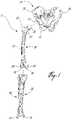
- FIG. 1is a front elevation view of leg bones involved in a hip replacement method in accordance with the present invention
- FIG. 2is a block diagram of a computer-assisted surgery system in accordance with the present invention.
- FIG. 3is a flow chart of a method of hip replacement surgery in accordance with the present invention.
- FIG. 4is a front elevation view of a canal digitizer in accordance with the present invention.
- FIG. 5Ais a longitudinal cross-section view of the canal digitizer
- FIG. 5Bis a side elevation view of a handle portion of the canal digitizer
- FIG. 6is a front elevation view of fingers of the canal digitizer
- FIG. 7is a front elevation view of one of the fingers having a stopper.
- FIG. 8is a front elevation view of the fingers of the canal digitizer centering the canal digitizer.
- FIG. 1is provided as reference for the description of the steps of the hip replacement surgery method described herein.
- the bonesare the pelvis 10 , the femur 20 , the tibia 30 and the fibula 40 .
- parts of these boneswill each be referenced by numerals from the same numeric decade.
- parts of the pelvise.g., the acetabulum 11
- a computer-assisted surgery systemis generally shown at 50 (hereinafter CAS system 50 ) and generally consists of a CAS controller 52 connected to sensor apparatus 54 .
- the sensor apparatus 54tracks for position and orientation tools 56 , to be described in detail with the description of the hip replacement surgery method of the present invention.
- the controller 52is typically a PC unit that has user interfaces by which a surgeon will receive or send information that will guide him during the hip replacement surgery. For instance, monitors, keyboard, mouse, and foot pedals are a few of the user interfaces that can be provided with the controller 52 .
- a database of the controller 52is illustrated separately as database 58 , and is typically the hard disk drive of the controller 52 .
- a discussion of the preferred system configurationwill follow the description of the method 100 .
- a method for hip replacement surgery in accordance with the present inventionis generally shown at 100 .
- the method 100is referred to in the singular, various choices of procedure will be given to the surgeon, as will be set forth in the forthcoming description, according to the preferences of the surgeon.
- a plurality of methodscan be derived from the method 100 according to the decisions of the surgeon.
- Step 102preparative steps for surgery are effected.
- general patient informationcan be entered into the CAS system 50 ( FIG. 2 ) for opening a patient file.
- a general patient profilecan be entered, consisting of the name, birth date, identification number, sex and the like, as well as more specific data pertaining to the surgery, such as leg length discrepancy (with the identification of the longer leg), if applicable.
- leg length discrepancyis measured using X-rays of the hip joint. More precisely, the leg length discrepancy is measured from the vertical comparison between the lesser trochanters. These X-rays are typically taken during the diagnostic stages leading to surgery, so they are usually available for hip joint surgery.
- the calibration of the various surgical tools to be usedis done.
- a calibration base and methodas set forth in International Publication No. WO 01/67979 A1 by Jutras et al., can be used for the calibration.
- correspondence between the tracking of the tools 56 and the display on the CAS controllercan be verified in further calibration steps included in Step 102 .
- the general patient informationcan be entered preoperatively. Moreover, the entering of the general patient information is straightforward such that the surgeon need not be involved. However, in order to minimize the preoperative procedures, all steps of method 100 can be performed at the beginning of the surgical session, during short time span preceding the surgery.
- Step 102Surgery is initiated between Step 102 and subsequent Decision 104 , by the surgeon exposing the hip joint. No computer assistance is required thereat.
- the dislocation of the femur from the pelvis (A)is preferred, as centers of rotation of the acetabulum 11 and the femoral head 21 ( FIG. 1 ) will be digitized independently from one another.
- (B) resecting the femoral head 21 from the femur 20 to then remove the femoral head 21 from the acetabulum 11the femoral head 21 will not be exposed out of the acetabulum 11 until it is resected, whereby the center of rotation thereof cannot be digitized with respect to the rest of the femur 20 . Therefore, a calculation based on an assumption will enable the calculation of a theoretical femoral center of rotation.
- dislocation (A) of the femur 20shows some level of difficulty, and involves risks such as fracture of the femur 20 (e.g., at the neck 22 ), and damage (e.g., hyperextension) to ligaments and muscle.
- Resection (B) of the femoral head 21can be preferred by surgeons as a safer procedure.
- Procedure (A)will initially be described in detail, followed by a description of procedure (B).
- Step 106following the choice of (A) dislocating the femur 20 from the pelvis 10 , the femoral head 21 is removed from the acetabulum 11 . Therefore, both the acetabulum 11 and the femoral head 21 are exposed.
- Step 108tracking references (included in the tools 56 ) are secured to the pelvis 10 and the femur 20 . Therefore, both the pelvis 10 and the femur 20 can be tracked for position and orientation in space simultaneously as a function of their respective tracking references, by the CAS system 50 of FIG. 2 .
- the tracking referenceswill remain anchored to their respective bones throughout the computer-assisted steps of surgery. It is pointed out that Step 108 could have been performed prior to Step 106 in procedure (A), although it is preferred that the tracking references not interfere with the dislocation of the femur 20 .
- the CAS system 50must thus be adapted to track at least two tracking references simultaneously, and in real-time.
- the tracking referencemay take the form of a marked point on one of the bone elements.
- a tracking referenceof the type being screwed to the bone element, can be secured to the pelvis 10 to be tracked for position and orientation, while the femur 20 is solely marked with a point (e.g., from a physical or visual marker).
- the marked pointis registered when the pelvis 10 and the femur 20 are in a known and reproducible posture. Thereafter, to update the position and orientation information relating to the femur 20 during surgery, the known and reproducible posture is reproduced and the marked point is digitized with a registration pointer.
- the femur 20may be marked with three nonlinear points to be used to position the portable tracking reference thereon.
- position and orientation information for the femur 20can be obtained by positioning the portable tracking reference with respect to the three nonlinear points.
- the portable tracking referenceis advantageous in that no screw holes are performed in the bone element.
- the method 100will be described with a tracking reference anchored to the femur 20 in accordance with a preferred embodiment of the present invention. Yet it is appreciated that the above described alternatives could be used instead of the anchored tracking reference of the femur 20 .
- Step 110digitization of a center of the femoral head 21 is performed.
- a registration pointerfrom the tools 56 ) having its tip tracked in space is used to register points on the surface of the femoral head 21 . Therefore, points of contact between the tip and a given surface can be registered as a function of the tracking reference (Step 108 ).
- the points on the surface of the femoral head 21are known as a function of the tracking of the respective tracking reference of the femur 20 .
- the CAS controller 52is equipped with software that will enable it to calculate the center of a sphere (i.e., the femoral head 21 ) from the collected points. Moreover, the center calculation software is adapted to perform a validation of the center calculation with the standard and maximum deviations. A rejection criterion for the validation of the center calculation can be recorded, for instance, during the setting of parameters in Step 102 .
- Step 110is preferred for obtaining a 3D model from which the femoral center of rotation will be calculated
- other equivalent methodsare contemplated for obtaining the femoral center of rotation.
- photogrammetric scanscan be used to rapidly create 3D models, or preoperative computerized tomography images can be gathered, from which the femoral head geometry can be established.
- the diameter of the sphere(i.e., of the femoral head 21 ) can be displayed, as such information can guide the surgeon in the choice of a femoral implant.
- the femoral center of rotation and the diameter of the femoral head 21can be used to correct displays on the CAS controller 52 .
- CT imagescan be shown on the display unit of the CAS controller 52
- the method 100is preferably free of CT images. Accordingly, general visual images of the pelvis 10 and of the femur 20 can be displayed for general reference, but these images can be scaled as a function of the center of rotation and diameters, calculated in Step 110 for the femur 20 in procedure (A), and to be calculated in Step 114 for the pelvis 10 .
- Step 112with the center of the femoral head 21 now identified in procedure (A) as a function of the tracking reference (Step 108 ), resection of the femoral head 21 is performed.
- Step 114digitization of the acetabular center of rotation is performed, by taking reference points on the surface of the acetabulum 11 , and using the center calculation software of the CAS controller 52 , set forth in Step 110 to find the acetabular center of rotation.
- the acetabular center of rotationis therefore known as a function of the tracking reference on the pelvis 10 . It is noted that in procedure (A) the digitization of the acetabular center of rotation (Step 114 ) is done independently from the digitization of the femoral center of rotation (Step 110 ).
- Step 116consists in the digitization of the acetabular and femoral coordinate systems, i.e., the acetabular and femoral frames of reference.
- the acetabular coordinate systemis digitized with the registration pointer.
- three pointsare taken on the pelvis 10 to create the acetabular coordinate system.
- FIG. 1there is one point on the iliac crest 12 of the operated side, one point on the contra lateral iliac crest 13 , and one point on one of the two pubic tubercles 14 of the pelvis 10 .
- the points digitized on the iliac crests 12 and 13are taken at the outermost anterior point of the iliac crests 12 and 13 .
- the points digitized on the iliac crests 12 and 13are preferably taken directly on the soft tissue covering the bone pelvis on the iliac crests, as the soft tissue is relatively thin thereon.
- the point on the pubic tubercle 14completes a first plane, the frontal plane.
- a second plane, the transverse planeis perpendicular to the frontal plane and includes the points on the iliac crests.
- a third plane, the sagittal plane,is perpendicular to the frontal and transverse planes.
- Supplemental information regarding the frontal planecan be obtained for various postures of a patient.
- trackable referencescan be used to gather information about sitting, standing and walking postures. This information can be used to adjust the orientation of the frontal plane, as these postures can provide information not available from the typical lying posture in which a patient is during surgery. This information can influence the anteversion positioning of the implants.
- the femoral coordinate systemis digitized in Step 116 by providing five points of reference on the leg to the CAS controller 52 , which is equipped with software that will create the femoral coordinate system.
- a first pointis taken on the tip of the greater trochanter 23 of the femur 20 , and will be defined as a starting point of an anatomical axis of the femur 20 .
- pointsare taken on the medial and lateral epicondyles 24 and 25 of the femur 20 , respectively.
- a midpoint between the medial epicondyle and lateral epicondyle points, in alignment therewith,is defined as an endpoint of the anatomical axis of the femur.
- the fourth and fifth pointsare taken on the medial malleolus of the tibia 30 and on the lateral malleolus 41 of the fibula 40 , with the leg being bent at the knee.
- the tibia 30stands on the posterior condyles 26 of the femur 20 .
- an aligned midpoint of the medial and lateral malleoli pointsis said to define a plane (i.e., sagittal plane) with the anatomical axis, with an axis of the knee being normal to the sagittal plane.
- the frontal planeis perpendicular to the sagittal plane, with the anatomical axis lying therein.
- the transverse planeis perpendicular to the sagittal and frontal planes, and can be positioned at any height.
- the projection values described hereinare based on the acetabular and the femoral coordinate systems.
- the projection valueswould be related to the alternative acetabular and femoral coordinate system.
- Step 108the first step of the surgical procedure following the decision to proceed with the resection (B) is Step 108 , wherein tracking references are secured to the pelvis 10 and to the femur 20 .
- Step 200consists in a registration of a relative position between the pelvis 10 and the femur 20 , as a function of the tracking references on each.
- the legis simply left in a straight position, and a relative position is acquired between tracking references secured to their respective bones.
- Step 112 of resecting the femoral head 21 from the femurfollows Step 200 . Accordingly, the acetabulum 11 of the pelvis 10 is exposed, and Step 114 , consisting in the digitization of the acetabular center of rotation, follows. As mentioned previously, the digitization of the acetabular center of rotation is as a function of the tracking reference secured to the pelvis 10 .
- Step 202includes the calculation of the femoral center of rotation.
- an assumptionis made that the acetabular center of rotation, calculated in the previous Step 114 in procedure (B), coincides with the femoral center of rotation.
- the position of the femoral center of rotationis calculated as a function of the relative position between the pelvis 10 and the femur 20 , obtained in Step 200 .
- Step 116follows, with the digitization of acetabular and femoral coordinate systems, i.e., acetabular and femoral frames of reference.
- Procedure (C)is the preferred embodiment and will most likely involve at least one fewer step. Some surgeons may prefer the procedure (D) as it involves work on the femur 20 , which has just been resected to lose its femoral head 21 (Step 112 ).
- Procedure (C)will initially be described, followed by a description of procedure (D).
- Step 152is the first step of procedure (C), and consists in the preparation of the acetabulum for insertion of the pelvic implant.
- the preparation of the acetabulumis performed by a reamer (from amongst the tools 56 of the CAS system 50 ).
- the previous acetabular center of rotationis known as a function of the tracking reference secured to the pelvis 10 , as it was acquired in previous Step 114 .
- the reameris tracked for position and orientation, such that an axis of actuation of the cup tool on the reamer is displayed on the CAS controller 52 .
- the diameter of the pelvic implant chosen by the surgeonwill be used to display a position of the new acetabular center of rotation in comparison to the digitized acetabular center of rotation (Step 114 ).
- the distance between the centers of rotationcan be displayed numerically (e.g., in mm) as a function of the acetabular coordinate system digitized in previous Step 116 .
- the anteversion and inclination of the actuation axis of the reamer, both as a function of the acetabular coordinate systemcan be given numerically (e.g., in degrees) to guide the surgeon in the reaming.
- the anteversionis calculated as the angle between an intersection of the acetabular frontal plane and transverse plane and the projection of the axis of the reamer on the acetabular transverse plane, and the inclination is the angle between the reamer axis and a cranial-caudal axis (y) on the sagittal plane of the acetabular coordinate system (Step 116 ).
- Step 154consists in the insertion of the pelvic implant in the acetabulum 11 .
- a tracked impactor(from amongst the tools 56 ) is preferably used.
- the pelvic implant sizehas been chosen, the diameter thereof and the known relation between the impactor and the pelvic implant is used with the tracking of the impactor to give the anteversion and the inclination of the pelvic implant.
- the distances between the current and the digitized centers of rotationcan be displayed. Therefore, the surgeon is guided during the use of the impactor so as to position the pelvic implant to a given position of the center of rotation thereof, and to a given orientation [with respect to anteversion and inclination (Step 152 )] to provide a maximal range of motion and stability of the leg.
- the pelvic implantis secured at this point to the pelvis 10 , it is possible to adjust the position and orientation of the pelvic implant.
- the tracked impactormay be reconnected to the pelvic implant to serve as a lever in manipulating the pelvic implant with the tracked impactor, allowing position and orientation information (e.g., anteversion and inclination) to be calculated from the tracking of the impactor.
- position and orientation informatione.g., anteversion and inclination
- points on the circular edge of the pelvic implantmay be digitized to define a plane, with the normal to this plane being used to calculate the anteversion and the inclination, as suggested previously to obtain this information for the acetabulum.
- This alternative approachis well suited for pelvic implants having screw holes for additional fixation, through which the implants can be altered in position and orientation.
- Step 156consists in the creation of a femoral target height.
- ( ⁇ PELVIC COR )is the deviation of the implant center of rotation (i.e., Step 154 ) with respect to the digitized acetabular center of rotation (i.e., Step 114 ), in cranial-caudal (y) direction (with a cranial deviation having a positive value), and (initial ⁇ LL ) is the initially acquired limb length discrepancy (Step 102 ).
- Step 158consists in the preparation of the femur 20 for the insertion of the femoral implant. More precisely, an axis of the intramedullary canal is digitized as a function of the tracking reference secured to the femur 20 by relating points in the canal 27 .
- the intramedullary canal 27is exposed by the resection of the femoral head 21 performed in Step 112 .
- the points in the canal 27are digitized by the insertion and tracking of a pointer (from amongst the tools 56 ) in the canal 27 , to various depths.
- a toolsuch as an awl
- the awlcan be inserted in the intramedullary canal to a depth wherein the inner diameter of the intramedullary canal is generally equivalent to the awl.
- the awlcan be considered to be generally centered in the intramedullary canal, whereby the axis of the awl can be registered as being the axis of the intramedullary canal.
- a canal digitizer in accordance with a preferred embodiment of the present inventionis generally shown at 300 .
- the canal digitizer 300can be used to accurately position a tip thereof in the center of the intramedullary canal 27 , and hence an axis centered in the canal 27 can be digitized.
- the canal digitizer 300will be described in further detail hereinafter.
- Step 158also includes the rasping of the intramedullary canal 27 in view of the insertion of the femoral implant therein.
- the raspis part of the tools 56 of the CAS system 50 , and is therefore tracked for position and orientation.
- the tooling portion of the rasp, which will alter the intramedullary canal 27 , and the femoral implantboth have a predetermined geometry. It is preferred to have rasps each having a tooling end with a generally similar geometry to the bone-engaging portion of the femoral implants.
- the raspscan be provided in different sizes, with an equivalent femoral implant for each size of rasp.
- the tracking of the rasp for position and orientation relative to the femoral coordinate system during alteration of the canalis used to calculate the current position and orientation of the femoral implant.
- a plurality of guiding parametersare displayed to the surgeon to quantify the current position and orientation of the femoral implant, and are listed below.
- the anteversion of the femoral implant as calculated from the tracked raspcan be displayed numerically (e.g., in degrees) based on the femoral coordinate system calculated in Step 116 . It is represented by the angle between the intersection of the frontal plane and the transverse plane and a projection of the neck axis (anticipated for the femoral implant) onto the transverse plane (Step 116 ).
- varus/valgus angle of the femoral implantis equivalent to the varus/valgus angle of the tracked rasp.
- the angleis measured between the projection of the intramedullary canal axis and the projection of the longitudinal rasp axis onto the femoral frontal plane (Step 116 ), and is displayed to the surgeon in degrees.
- Another guiding parameter to be provided to the surgeonis the distance between the previous femoral center of rotation [i.e., digitized in Step 106 for the dislocation procedure (A), or calculated in Step 202 for the resection procedure (B)] and the current femoral center of rotation.
- the current femoral center of rotationis calculated as a function of the femoral implant geometry (e.g., the ball head size) and the tracking of the rasp.
- the distancecan be given in X, Y and Z values (e.g., in mm) according to the femoral coordinate system (Step 116 ).
- ( ⁇ FEMUR COR )is the Y value calculated above in Step 158
- ( ⁇ PELVIC COR ) and (initial ⁇ LL )have been calculated in Step 156 .
- the current leg length discrepancycan be displayed by the CAS system 50 as an overall leg length, or as a relative value between leg lengths, with the value 0 representing legs of equal length.
- the offsetis the distance between the acetabular center of rotation and the axis of the implant (i.e., the anatomical axis of the femur as defined previously) on the transverse plane, and is thus directly related to the size of the femoral implant. It is pointed out that a type of femoral implant contemplated for the above described method 100 can be provided in various sizes, and a size of femoral implant can have various femoral centers of rotation along the neck of the implant. A proper identification of the size of the femoral implant must therefore be provided as it will have an effect on both the offset and the limb length.
- Step 160consists in the insertion of the femoral implant in the intramedullary canal 27 . It is anticipated that the femoral implant will be positioned and orientated substantially as calculated from the tracking of the tool 56 that has previously altered the intramedullary canal. However, it is also contemplated to track the femoral implant for position and orientation with a position of the center of rotation of the implant being calculable by the CAS controller 52 as a function of the tracking of the femoral implant. Such a step would ensure a precise position of the implant.
- the CAS controller 52can change its display of the femur 20 upon the insertion of the femoral implant, or of the pelvis 10 upon the insertion of the pelvic implant (Step 154 ).
- Step 162consists in the analysis of the range of motion of the hip joint.
- the range of motioncan be assessed by the following parameters: the angles of flexion/extension, of adduction/abduction, and the internal/external rotation of the leg. These angles are measured based on both coordinate systems digitized in Step 116 , and the minimal and maximal angle values can be recorded as part of the patient profile.
- Step 164signals the end of the computer assistance to the hip replacement surgery.
- procedure (D)involving the femur preparation prior to the pelvic implant insertion, will now be described.
- Step 250follows Decision 150 , and consists in the same operations effected in Step 158 .
- the femur 20is prepared for the insertion of the femoral implant.
- an assumptionis made that the actual pelvic implant center of rotation will be coincident with the digitized acetabulum center of rotation (Step 114 ).
- the digitized acetabulum center of rotationwill thus be used in providing the various guiding parameters to the surgeon.
- procedure (D)comprises Steps 152 , 154 and 156 , as performed in procedure (C). It is pointed out that in Step 154 , the actual pelvic implant center of rotation is obtained.
- Step 252a comparison is made between the actual pelvic implant center of rotation and the digitized acetabulum center of rotation, that has been used for the preparation of the femur in Step 250 . If there is a difference between these values, femoral correction may be required, as shown in Step 158 . Otherwise, the femoral implant can be inserted in the femur.
- Steps 162 and 164follow to end procedure (D).
- an operatore.g., surgeon
- the operator Sinteracts with the controller 52 of the CAS system 50 using the user interfaces of the controller 52 (e.g., mouse, display unit, keyboard, sound emitter).
- the controller 52will provide guiding information on the method 100 to the operator S throughout CAS.
- the guiding informationis for instance retrieved by the controller 52 from the database 58 , and will guide the operator S in handling the tools 56 .
- the tools 56are each trackable in space for position and orientation by the sensing apparatus 54 , such that a position and/or orientation of given components thereof are calculable.
- the tools 56include the reference tools, such as the trackable references securable to the bones (Step 108 ), for the creation of frames of reference of the bones.
- Another one of the required tools 56is a registration tool that will enable to gather surface information about the bones (e.g., Steps 110 , 114 , 116 , etc.).
- the registration toolcan be a registration pointer, a tracked photogrammetric sensor, or the like.
- a bone altering toolis included in the required tools 56 , such as a reamer and a rasp, for which uses have been described previously in Steps 152 and 158 , respectively.
- the tools 56include the pelvic (impactor) and the femoral implant, that can be tracked for position and orientation, to guide the operator during the insertion. It is pointed out that information relating to the tools (e.g., geometry, position of tip) is either known by the controller 52 (or retrievable from the database 58 ) or determinable using various steps of calibration.
- the sensing apparatus 54is connected to the controller 52 , and transfers position and orientation tracking to the controller 52 .
- the position and orientation trackingsare used by the controller 52 to calculate parameters pertaining to the CAS. More precisely, the position and orientation trackings of the reference tool and registration tool are used to create frames of reference of the pelvis and the femur, as described in Steps 110 , 114 and 116 .
- the frame of reference informationis provided to the operator S, for instance using the display unit of the controller 52 .
- an initial center of rotationis calculated with respect to the frame of reference, as described in Step 114 .
- the acetabular center of rotationwill be used with the pelvic frame of reference as references for the alteration of the acetabulum in view of the insertion of the pelvic implant therein.
- a desired femoral implant positionis calculated by the controller 52 in accordance with the Step 156 , and will be used as a reference for the alteration of the intramedullary canal in view of the insertion of the femoral implant therein.
- the database 58stores information that is retrieved by the controller 52 to make the calculation.
- the current pelvic and femoral implant positions and orientationsare calculated as a function of the position and orientation tracking of the bone altering tools, and of the geometry of the respective implants. This is performed in accordance with Steps 154 and 158 / 252 of the method 100 .
- the controller 52uses the output of the sensor apparatus 54 and information stored in the database 58 for the calculations, that will be displayed for guiding the operator S.
- the CAS system 50can operate with active or passive tracking.
- the sensor apparatus 54is a NDI Polaris® optical tracking apparatus, with appropriate operating software in the controller 52 .
- the Polaris® optical tracking apparatuspassive detectable devices, such as retro-reflective spheres, are used in patterns to be tracked in space for position and orientation.
- Each one of the tools 56 that requires to be trackedhas an own detectable pattern.
- the CAS system 50must guide the surgeon throughout the method 100 , and relevant information is displayed to ensure the surgeon follows the proper Steps of operation. For instance, when leg length discrepancy values are given, the cranial-caudal convention can be displayed to explain the reading obtained. Animations can be initiated automatically to guide the surgeon, for example, in taking reference points on the various bones, such that the reference points are taken in a given order, or at the right locations.
- the canal digitizer 300is shown having an elongated shaft 302 , a handle portion 304 , a piston 306 , a detectable device base 308 , and a centering mechanism 309 .
- the shaft 302is hollow, and has an outer surface 310 and a free open end 312 .
- the shaft 302is graduated such that when the digitizer 300 is inserted in a canal, the tool handler has an indication of the depth of insertion of the digitizer 300 .
- a splitter 314is provided at the free open end 312 , and is held between a pair of extensions 316 .
- the handle portion 304has a pair of radial flanges 320 .
- the detectable device base 308projects outwardly from a distal one of the radial flanges 320 .
- the proximal flange 320is adjacent to the piston 306 , and is used as leverage by the tool handler to push the piston 306 inwardly.
- a flared tip 322is adjacent to the distal flange 320 , and will enable the digitizer 300 to be centered when abutting against walls of a canal, if the elongated shaft 302 is completely inserted in the canal.
- the handle portion 304also defines an inner cavity 324 , having a guiding channel 325 adjacent to the proximal flange 320 , for a purpose to be described hereinafter.
- a flared adapter 323can be optionally provided in sliding engagement on the shaft 302 .
- the flared adapter 323serves the same purpose as the flared tip 322 of the handle portion 304 , but is displaceable on the shaft 302 so as be used at various depths of insertion of the shaft 302 in the canal.
- the centering mechanism 309has a slender rod 326 , concentrically disposed in the shaft 302 .
- the rod 326is connected to the piston 306 at a proximal end thereof, and has a pair of fingers, 328 and 330 , pivotally mounted thereto at a distal end thereof, as best seen in FIG. 6 .
- a spring 332surrounds a proximal portion of the rod 326 , and interacts with a surface of the inner cavity 324 of the handle portion 304 such that the rod 326 is biased in the proximal direction, i.e., the piston 306 is held away from the handle portion 304 .
- the rod 326moves in the distal direction, but retracts back proximally upon release of the piston 306 .
- the spring 332is fixed at a proximal end thereof to the piston 306 , for instance, by welding therebetween.
- the piston 306has a pin 327 at a distal end thereof.
- the pin 327cooperatively engages into the guiding channel 325 of the cavity 324 of the handle portion 304 . Accordingly, the assembly of the piston 306 /centering mechanism 309 can be readily separated from the shaft 302 /handle portion 304 assembly by guiding the former from the latter until the pin 327 is out of the guiding channel 325 .
- the guiding channel 325has an elbow portion 325 ′ ( FIG. 5B ) and a straight portion 325 ′′, such that once the pin 327 is past the elbow portion 325 ′ ( FIG.
- the piston 306 /centering mechanism 309 assemblyis captive and free to translate in the straight portion 325 ′′, being held captive with respect to the handle portion 304 .
- This assemblyis preferred to facilitate the sterilization of the inner cavity 324 and of the interior of the shaft 302 .
- the fingers 328 and 330at the distal end of the rod 326 , are kept with their respective tips 329 and 331 separated from one another by a stopper 334 protruding from the finger 328 . Therefore, the fingers 328 and 330 define a slot 336 .
- the fingers 328 and 330are held by pivot 338 .
- the tips 329 and 331are both at a same distance from the pivot 338 .
- the rod 326moves towards the free open end 312 of the shaft 302 , such that the splitter 314 engages with the slot 336 .
- the fingers 328 and 330are guided away from one another, as best seen in FIG. 8 .
- the fingers 328 and 330will center the digitizer 300 in the canal.
- Other configurationsare possible. For instance, a pivotless solution can also be imagined where fingers 328 and 330 would be two blades protruding from a same solid and the flexion of the material would split the blades apart when engaged on the splitter 314 . It has also been thought to equip the elongated shaft 302 with an inflatable end that will be self-centered in the intramedullary canal upon being inflated.
- the rod 326has a given length, such that the fingers 328 and 330 at an end thereof do not interfere with the splitter 314 when the assembly of the piston 306 /centering mechanism 309 (including the rod 326 ) is screwingly inserted in the shaft 302 /handle portion 304 . Such interference would prevent the pin 327 from going past the elbow portion 325 ′ of the guiding channel 325 in the inner cavity 324 .
- Another possible configurationis to provide an axial rotational degree of freedom between the piston 306 and the rod 326 . Therefore, an engagement of the fingers 328 and 330 with the splitter 314 would not prevent the engagement of the pin 327 of the piston 306 in the guiding channel 325 of the inner cavity 324 . This can be achieved by providing an annular groove 339 on an end of the rod 326 , and corresponding engagement pins 341 between the grooves 339 and the piston 306 .
- the digitizer 300is used with a tracking system, such as CAS system 50 ( FIG. 2 ).
- CAS system 50is preferably equipped with an optical tracking system
- the digitizer 50is shown having the detectable device base 308 consisting of a support for detectable devices. More precisely, the detectable device base 308 has an arm 342 with a support plate 344 at a free end thereof.
- Snap-fit fingers 346are provided for receiving detectable devices in snap-fit engagement therewith.
- the detectable devicescan be retro-reflective detectable spheres, one of which is shown at 348 in FIG. 4 on the verge of being snap-fitted to one of the fingers 346 .
- the digitizer 300may also be equipped with an active detectable device, provided that the tracking system is configured therefor.
- the tracking system used with the digitizer 300must know the relation between the detectable device on the base 308 and the tip of the shaft 302 .
- the relationcan be determined in calibration using a calibration base (as explained previously for the tools 56 of FIG. 2 ). Accordingly, when the digitizer 300 is stabilized in the canal, the position and orientation of the detectable device can be registered, and a center point of the canal can be calculated thereafter, where the tip of the shaft 302 is located.
Landscapes
- Health & Medical Sciences (AREA)
- Life Sciences & Earth Sciences (AREA)
- Engineering & Computer Science (AREA)
- Surgery (AREA)
- General Health & Medical Sciences (AREA)
- Medical Informatics (AREA)
- Biomedical Technology (AREA)
- Veterinary Medicine (AREA)
- Public Health (AREA)
- Animal Behavior & Ethology (AREA)
- Heart & Thoracic Surgery (AREA)
- Molecular Biology (AREA)
- Nuclear Medicine, Radiotherapy & Molecular Imaging (AREA)
- Oral & Maxillofacial Surgery (AREA)
- Orthopedic Medicine & Surgery (AREA)
- Dentistry (AREA)
- Physics & Mathematics (AREA)
- General Physics & Mathematics (AREA)
- Pathology (AREA)
- Biophysics (AREA)
- Transplantation (AREA)
- Computational Mathematics (AREA)
- Business, Economics & Management (AREA)
- Robotics (AREA)
- Theoretical Computer Science (AREA)
- Chemical & Material Sciences (AREA)
- Medicinal Chemistry (AREA)
- Algebra (AREA)
- Educational Technology (AREA)
- Educational Administration (AREA)
- Mathematical Analysis (AREA)
- Mathematical Optimization (AREA)
- Mathematical Physics (AREA)
- Pure & Applied Mathematics (AREA)
- Cardiology (AREA)
- Vascular Medicine (AREA)
- Physical Education & Sports Medicine (AREA)
- Human Computer Interaction (AREA)
- Radiology & Medical Imaging (AREA)
- Prostheses (AREA)
Abstract
Description
(target height)=(ΔPELVIC COR)−(initial ΔLL),
(current ΔLL)=(initial ΔLL)−(ΔPELVIC COR)+(ΔFEMUR COR),
Claims (13)
Priority Applications (1)
| Application Number | Priority Date | Filing Date | Title |
|---|---|---|---|
| US16/249,333US11311339B2 (en) | 2002-10-04 | 2019-01-16 | Computer-assisted hip replacement surgery |
Applications Claiming Priority (5)
| Application Number | Priority Date | Filing Date | Title |
|---|---|---|---|
| US41580902P | 2002-10-04 | 2002-10-04 | |
| US46580503P | 2003-04-28 | 2003-04-28 | |
| US10/677,432US9339277B2 (en) | 2002-10-04 | 2003-10-03 | Computer-assisted hip replacement surgery |
| US15/131,552US10219865B2 (en) | 2002-10-04 | 2016-04-18 | Computer-assisted hip replacement surgery |
| US16/249,333US11311339B2 (en) | 2002-10-04 | 2019-01-16 | Computer-assisted hip replacement surgery |
Related Parent Applications (1)
| Application Number | Title | Priority Date | Filing Date |
|---|---|---|---|
| US15/131,552ContinuationUS10219865B2 (en) | 2002-10-04 | 2016-04-18 | Computer-assisted hip replacement surgery |
Publications (2)
| Publication Number | Publication Date |
|---|---|
| US20190307509A1 US20190307509A1 (en) | 2019-10-10 |
| US11311339B2true US11311339B2 (en) | 2022-04-26 |
Family
ID=32738083
Family Applications (5)
| Application Number | Title | Priority Date | Filing Date |
|---|---|---|---|
| US10/677,321AbandonedUS20050021043A1 (en) | 2002-10-04 | 2003-10-03 | Apparatus for digitizing intramedullary canal and method |
| US10/677,432Active2031-02-15US9339277B2 (en) | 2002-10-04 | 2003-10-03 | Computer-assisted hip replacement surgery |
| US10/530,192Active2027-09-22US7877131B2 (en) | 2002-10-04 | 2003-10-06 | Method for providing pelvic orientation information in computer-assisted surgery |
| US15/131,552Expired - LifetimeUS10219865B2 (en) | 2002-10-04 | 2016-04-18 | Computer-assisted hip replacement surgery |
| US16/249,333Expired - LifetimeUS11311339B2 (en) | 2002-10-04 | 2019-01-16 | Computer-assisted hip replacement surgery |
Family Applications Before (4)
| Application Number | Title | Priority Date | Filing Date |
|---|---|---|---|
| US10/677,321AbandonedUS20050021043A1 (en) | 2002-10-04 | 2003-10-03 | Apparatus for digitizing intramedullary canal and method |
| US10/677,432Active2031-02-15US9339277B2 (en) | 2002-10-04 | 2003-10-03 | Computer-assisted hip replacement surgery |
| US10/530,192Active2027-09-22US7877131B2 (en) | 2002-10-04 | 2003-10-06 | Method for providing pelvic orientation information in computer-assisted surgery |
| US15/131,552Expired - LifetimeUS10219865B2 (en) | 2002-10-04 | 2016-04-18 | Computer-assisted hip replacement surgery |
Country Status (7)
| Country | Link |
|---|---|
| US (5) | US20050021043A1 (en) |
| EP (4) | EP1545368B1 (en) |
| JP (2) | JP2006509609A (en) |
| AT (4) | ATE424776T1 (en) |
| AU (2) | AU2003273680A1 (en) |
| DE (2) | DE60330719D1 (en) |
| WO (2) | WO2004030556A2 (en) |
Cited By (2)
| Publication number | Priority date | Publication date | Assignee | Title |
|---|---|---|---|---|
| US11944392B2 (en) | 2016-07-15 | 2024-04-02 | Mako Surgical Corp. | Systems and methods for guiding a revision procedure |
| US12370061B2 (en) | 2019-08-29 | 2025-07-29 | Mako Surgical Corp. | Robotic surgery system for augmented arthroplasty procedures |
Families Citing this family (228)
| Publication number | Priority date | Publication date | Assignee | Title |
|---|---|---|---|---|
| US20050113846A1 (en)* | 2001-02-27 | 2005-05-26 | Carson Christopher P. | Surgical navigation systems and processes for unicompartmental knee arthroplasty |
| US7547307B2 (en) | 2001-02-27 | 2009-06-16 | Smith & Nephew, Inc. | Computer assisted knee arthroplasty instrumentation, systems, and processes |
| DE60232315D1 (en)* | 2001-02-27 | 2009-06-25 | Smith & Nephew Inc | SURGICAL NAVIGATION SYSTEM FOR PARTIAL KNEE JOINT CONSTRUCTION |
| WO2003053244A2 (en)* | 2001-12-11 | 2003-07-03 | École De Technologie Supérieure | Method of calibration for the representation of knee kinematics and harness for use therewith |
| JP2005516724A (en)* | 2002-02-11 | 2005-06-09 | スミス アンド ネフュー インコーポレーテッド | Image guided fracture reduction |
| WO2004014219A2 (en)* | 2002-08-09 | 2004-02-19 | Kinamed, Inc. | Non-imaging tracking tools and method for hip replacement surgery |
| JP2006509609A (en)* | 2002-10-04 | 2006-03-23 | オルトソフト インコーポレイテッド | Computer-aided hip replacement surgery |
| WO2004069040A2 (en)* | 2003-02-04 | 2004-08-19 | Z-Kat, Inc. | Method and apparatus for computer assistance with intramedullary nail procedure |
| EP1605810A2 (en)* | 2003-02-04 | 2005-12-21 | Z-Kat, Inc. | Computer-assisted knee replacement apparatus and method |
| US20050021037A1 (en)* | 2003-05-29 | 2005-01-27 | Mccombs Daniel L. | Image-guided navigated precision reamers |
| CA2439850A1 (en) | 2003-09-04 | 2005-03-04 | Orthosoft Inc. | Universal method for determining acetabular and femoral implant positions during navigation |
| US7862570B2 (en) | 2003-10-03 | 2011-01-04 | Smith & Nephew, Inc. | Surgical positioners |
| US20050124988A1 (en)* | 2003-10-06 | 2005-06-09 | Lauralan Terrill-Grisoni | Modular navigated portal |
| US7764985B2 (en)* | 2003-10-20 | 2010-07-27 | Smith & Nephew, Inc. | Surgical navigation system component fault interfaces and related processes |
| US20050085822A1 (en)* | 2003-10-20 | 2005-04-21 | Thornberry Robert C. | Surgical navigation system component fault interfaces and related processes |
| ATE495706T1 (en) | 2003-11-14 | 2011-02-15 | Smith & Nephew Inc | ADJUSTABLE SURGICAL CUTTING SYSTEMS |
| US20050113659A1 (en)* | 2003-11-26 | 2005-05-26 | Albert Pothier | Device for data input for surgical navigation system |
| WO2005072629A1 (en)* | 2004-01-16 | 2005-08-11 | Smith & Nephew, Inc. | Computer-assisted ligament balancing in total knee arthroplasty |
| US20050159759A1 (en)* | 2004-01-20 | 2005-07-21 | Mark Harbaugh | Systems and methods for performing minimally invasive incisions |
| WO2005070319A1 (en)* | 2004-01-22 | 2005-08-04 | Smith & Nephew, Inc. | Methods, systems, and apparatuses for providing patient-mounted surgical navigational sensors |
| US20050267353A1 (en)* | 2004-02-04 | 2005-12-01 | Joel Marquart | Computer-assisted knee replacement apparatus and method |
| FR2865928B1 (en)* | 2004-02-10 | 2006-03-17 | Tornier Sa | SURGICAL DEVICE FOR IMPLANTATION OF A TOTAL HIP PROSTHESIS |
| US20080132783A1 (en)* | 2004-03-05 | 2008-06-05 | Ian Revie | Pelvis Registration Method and Apparatus |
| US20070073306A1 (en)* | 2004-03-08 | 2007-03-29 | Ryan Lakin | Cutting block for surgical navigation |
| US20050234465A1 (en)* | 2004-03-31 | 2005-10-20 | Mccombs Daniel L | Guided saw with pins |
| CA2561493A1 (en) | 2004-03-31 | 2005-10-20 | Smith & Nephew, Inc. | Methods and apparatuses for providing a reference array input device |
| US20050234466A1 (en)* | 2004-03-31 | 2005-10-20 | Jody Stallings | TLS adjustable block |
| US20050228404A1 (en)* | 2004-04-12 | 2005-10-13 | Dirk Vandevelde | Surgical navigation system component automated imaging navigation and related processes |
| JP4808704B2 (en)* | 2004-04-15 | 2011-11-02 | スミス アンド ネフュー インコーポレーテッド | Detachable and repositionable reference frame for computer-assisted surgery |
| EP1737375B1 (en) | 2004-04-21 | 2021-08-11 | Smith & Nephew, Inc | Computer-aided navigation systems for shoulder arthroplasty |
| US20050279368A1 (en)* | 2004-06-16 | 2005-12-22 | Mccombs Daniel L | Computer assisted surgery input/output systems and processes |
| US20060004284A1 (en)* | 2004-06-30 | 2006-01-05 | Frank Grunschlager | Method and system for generating three-dimensional model of part of a body from fluoroscopy image data and specific landmarks |
| US8290570B2 (en) | 2004-09-10 | 2012-10-16 | Stryker Leibinger Gmbh & Co., Kg | System for ad hoc tracking of an object |
| JP2008521574A (en)* | 2004-12-02 | 2008-06-26 | スミス アンド ネフュー インコーポレーテッド | System providing a reference plane for attaching an acetabular cup |
| AU2005311751A1 (en)* | 2004-12-02 | 2006-06-08 | Smith & Nephew, Inc. | Systems, methods, and apparatus for automatic software flow using instrument detection during computer-aided surgery |
| DE102005003318A1 (en)* | 2005-01-17 | 2006-07-27 | Aesculap Ag & Co. Kg | Displaying method for the position of a medical instrument in which planes and an intersection line are defined and determined for the femur and inserted instrument |
| DE102005003317A1 (en)* | 2005-01-17 | 2006-07-27 | Aesculap Ag & Co. Kg | Method for determining the neutral position of a femur relative to a pelvic bone and apparatus for carrying out this method |
| US20060161051A1 (en)* | 2005-01-18 | 2006-07-20 | Lauralan Terrill-Grisoni | Method of computer-assisted ligament balancing and component placement in total knee arthroplasty |
| US20060189864A1 (en)* | 2005-01-26 | 2006-08-24 | Francois Paradis | Computer-assisted hip joint resurfacing method and system |
| WO2006091704A1 (en) | 2005-02-22 | 2006-08-31 | Smith & Nephew, Inc. | In-line milling system |
| US20070021644A1 (en)* | 2005-03-02 | 2007-01-25 | Woolson Steven T | Noninvasive methods, apparatus, kits, and systems for intraoperative position and length determination |
| GB0507243D0 (en)* | 2005-04-09 | 2005-05-18 | Depuy Int Ltd | Acetabular cup positioning |
| EP1885274B1 (en)* | 2005-06-02 | 2018-04-25 | Orthosoft, Inc. | Leg alignment for surgical parameter measurement in hip replacement surgery |
| DE102005028831A1 (en) | 2005-06-15 | 2006-12-28 | Aesculap Ag & Co. Kg | Method and surgical navigation system for producing a receiving cavity for an acetabular cup |
| US20070016008A1 (en)* | 2005-06-23 | 2007-01-18 | Ryan Schoenefeld | Selective gesturing input to a surgical navigation system |
| US7840256B2 (en) | 2005-06-27 | 2010-11-23 | Biomet Manufacturing Corporation | Image guided tracking array and method |
| US7458989B2 (en) | 2005-06-30 | 2008-12-02 | University Of Florida Rearch Foundation, Inc. | Intraoperative joint force measuring device, system and method |
| US20070038059A1 (en)* | 2005-07-07 | 2007-02-15 | Garrett Sheffer | Implant and instrument morphing |
| WO2007010330A1 (en)* | 2005-07-15 | 2007-01-25 | Gulhivair Holding Sa | Device and method for a computer-assisted internal bone digitising for orthopaedic surgery and traumatology |
| US7407075B2 (en)* | 2005-08-15 | 2008-08-05 | Tyco Healthcare Group Lp | Staple cartridge having multiple staple sizes for a surgical stapling instrument |
| US20070073133A1 (en)* | 2005-09-15 | 2007-03-29 | Schoenefeld Ryan J | Virtual mouse for use in surgical navigation |
| US7643862B2 (en)* | 2005-09-15 | 2010-01-05 | Biomet Manufacturing Corporation | Virtual mouse for use in surgical navigation |
| US7835784B2 (en) | 2005-09-21 | 2010-11-16 | Medtronic Navigation, Inc. | Method and apparatus for positioning a reference frame |
| US20070118055A1 (en)* | 2005-11-04 | 2007-05-24 | Smith & Nephew, Inc. | Systems and methods for facilitating surgical procedures involving custom medical implants |
| WO2007087351A2 (en)* | 2006-01-24 | 2007-08-02 | Carnegie Mellon University | Method, apparatus, and system for computer-aided tracking, navigation, and motion teaching |
| US8167823B2 (en) | 2009-03-24 | 2012-05-01 | Biomet Manufacturing Corp. | Method and apparatus for aligning and securing an implant relative to a patient |
| US9339278B2 (en) | 2006-02-27 | 2016-05-17 | Biomet Manufacturing, Llc | Patient-specific acetabular guides and associated instruments |
| US9173661B2 (en) | 2006-02-27 | 2015-11-03 | Biomet Manufacturing, Llc | Patient specific alignment guide with cutting surface and laser indicator |
| US9345548B2 (en) | 2006-02-27 | 2016-05-24 | Biomet Manufacturing, Llc | Patient-specific pre-operative planning |
| US8337426B2 (en) | 2009-03-24 | 2012-12-25 | Biomet Manufacturing Corp. | Method and apparatus for aligning and securing an implant relative to a patient |
| US20150335438A1 (en) | 2006-02-27 | 2015-11-26 | Biomet Manufacturing, Llc. | Patient-specific augments |
| US9907659B2 (en) | 2007-04-17 | 2018-03-06 | Biomet Manufacturing, Llc | Method and apparatus for manufacturing an implant |
| US8591516B2 (en) | 2006-02-27 | 2013-11-26 | Biomet Manufacturing, Llc | Patient-specific orthopedic instruments |
| US9289253B2 (en) | 2006-02-27 | 2016-03-22 | Biomet Manufacturing, Llc | Patient-specific shoulder guide |
| US8603180B2 (en) | 2006-02-27 | 2013-12-10 | Biomet Manufacturing, Llc | Patient-specific acetabular alignment guides |
| US8407067B2 (en) | 2007-04-17 | 2013-03-26 | Biomet Manufacturing Corp. | Method and apparatus for manufacturing an implant |
| US9918740B2 (en) | 2006-02-27 | 2018-03-20 | Biomet Manufacturing, Llc | Backup surgical instrument system and method |
| CA2644574C (en)* | 2006-03-17 | 2016-11-08 | Zimmer, Inc. | Methods of predetermining the contour of a resected bone surface and assessing the fit of a prosthesis on the bone |
| US8165659B2 (en) | 2006-03-22 | 2012-04-24 | Garrett Sheffer | Modeling method and apparatus for use in surgical navigation |
| WO2007107006A1 (en)* | 2006-03-23 | 2007-09-27 | Orthosoft Inc. | Method and system for tracking tools in computer-assisted surgery |
| US9795399B2 (en) | 2006-06-09 | 2017-10-24 | Biomet Manufacturing, Llc | Patient-specific knee alignment guide and associated method |
| CA2658510C (en) | 2006-07-21 | 2013-01-15 | Orthosoft Inc. | Non-invasive tracking of bones for surgery |
| EP1882457B1 (en)* | 2006-07-25 | 2012-03-28 | BrainLAB AG | Method and device for representing the orientation of an object to ball joints |
| AU2007281000A1 (en)* | 2006-08-03 | 2008-02-07 | Orthosoft Inc. | Computer-assisted surgery tools and system |
| US7594933B2 (en)* | 2006-08-08 | 2009-09-29 | Aesculap Ag | Method and apparatus for positioning a bone prosthesis using a localization system |
| JP4986183B2 (en)* | 2006-08-08 | 2012-07-25 | アエスキュラップ アーゲー | Method and apparatus for positioning an artificial bone with a position measurement system |
| US8400312B2 (en)* | 2006-10-10 | 2013-03-19 | Saga University | Operation assisting system |
| US20080146969A1 (en)* | 2006-12-15 | 2008-06-19 | Kurtz William B | Total joint replacement component positioning as predetermined distance from center of rotation of the joint using pinless navigation |
| EP1952779B1 (en)* | 2007-02-01 | 2012-04-04 | BrainLAB AG | Method and system for Identification of medical instruments |
| US8784425B2 (en) | 2007-02-28 | 2014-07-22 | Smith & Nephew, Inc. | Systems and methods for identifying landmarks on orthopedic implants |
| US8814868B2 (en) | 2007-02-28 | 2014-08-26 | Smith & Nephew, Inc. | Instrumented orthopaedic implant for identifying a landmark |
| US8934961B2 (en) | 2007-05-18 | 2015-01-13 | Biomet Manufacturing, Llc | Trackable diagnostic scope apparatus and methods of use |
| US8603093B2 (en) | 2007-06-07 | 2013-12-10 | Sam Hakki | Method of determining acetabular center axis |
| US20080319491A1 (en) | 2007-06-19 | 2008-12-25 | Ryan Schoenefeld | Patient-matched surgical component and methods of use |
| US8382765B2 (en) | 2007-08-07 | 2013-02-26 | Stryker Leibinger Gmbh & Co. Kg. | Method of and system for planning a surgery |
| US9179983B2 (en) | 2007-08-14 | 2015-11-10 | Zimmer, Inc. | Method of determining a contour of an anatomical structure and selecting an orthopaedic implant to replicate the anatomical structure |
| DE102007049668B3 (en) | 2007-10-17 | 2009-04-16 | Aesculap Ag | Method and device for determining the angular position of an acetabular cup in a pelvic bone |
| DE102007049671A1 (en) | 2007-10-17 | 2009-04-30 | Aesculap Ag | Method and device for determining the frontal plane of the pelvic bone |
| US8986309B1 (en) | 2007-11-01 | 2015-03-24 | Stephen B. Murphy | Acetabular template component and method of using same during hip arthrosplasty |
| US8267938B2 (en) | 2007-11-01 | 2012-09-18 | Murphy Stephen B | Method and apparatus for determining acetabular component positioning |
| US10335236B1 (en) | 2007-11-01 | 2019-07-02 | Stephen B. Murphy | Surgical system using a registration device |
| US11992271B2 (en) | 2007-11-01 | 2024-05-28 | Stephen B. Murphy | Surgical system using a registration device |
| US20090125117A1 (en)* | 2007-11-14 | 2009-05-14 | Francois Paradis | Leg alignment and length measurement in hip replacement surgery |
| ES2784016T3 (en)* | 2007-11-19 | 2020-09-21 | Blue Ortho | Hip implant registration in computer-assisted surgery |
| US8617171B2 (en)* | 2007-12-18 | 2013-12-31 | Otismed Corporation | Preoperatively planning an arthroplasty procedure and generating a corresponding patient specific arthroplasty resection guide |
| ES2595366T3 (en) | 2008-01-09 | 2016-12-29 | Stryker European Holdings I, Llc | Computer-assisted stereotactic surgery system based on a three-dimensional visualization |
| US8571637B2 (en)* | 2008-01-21 | 2013-10-29 | Biomet Manufacturing, Llc | Patella tracking method and apparatus for use in surgical navigation |
| US9220514B2 (en) | 2008-02-28 | 2015-12-29 | Smith & Nephew, Inc. | System and method for identifying a landmark |
| GB0803625D0 (en)* | 2008-02-28 | 2008-04-02 | Depuy Int Ltd | Acetabular alignment guide |
| GB0803725D0 (en) | 2008-02-29 | 2008-04-09 | Depuy Int Ltd | Surgical apparatus and procedure |
| WO2009114829A2 (en)* | 2008-03-13 | 2009-09-17 | Thornberry Robert L | Computer-guided system for orienting the acetabular cup in the pelvis during total hip replacement surgery |
| FR2932677B1 (en)* | 2008-06-20 | 2010-06-25 | Univ Bretagne Occidentale | SYSTEM FOR ASSISTING THE IMPLANTATION OF A HIP PROSTHESIS ON AN INDIVIDUAL. |
| US9125678B2 (en) | 2008-09-17 | 2015-09-08 | Inertial Orthopaedic Navigation Solutions Pty Ltd | Surgical orientation system and associated method |
| US8078440B2 (en) | 2008-09-19 | 2011-12-13 | Smith & Nephew, Inc. | Operatively tuning implants for increased performance |
| GB0820219D0 (en) | 2008-11-05 | 2008-12-10 | Imp Innovations Ltd | Hip resurfacing |
| US8588892B2 (en) | 2008-12-02 | 2013-11-19 | Avenir Medical Inc. | Method and system for aligning a prosthesis during surgery using active sensors |
| EP2216728B1 (en)* | 2009-02-04 | 2012-04-04 | BrainLAB AG | Method and device for determining a characteristic of an anatomical structure |
| US8945147B2 (en) | 2009-04-27 | 2015-02-03 | Smith & Nephew, Inc. | System and method for identifying a landmark |
| US9031637B2 (en) | 2009-04-27 | 2015-05-12 | Smith & Nephew, Inc. | Targeting an orthopaedic implant landmark |
| GB0907650D0 (en) | 2009-05-05 | 2009-07-22 | Depuy Int Ltd | Alignment guide |
| US9655628B2 (en) | 2009-05-06 | 2017-05-23 | Blue Ortho | Reduced invasivity fixation system for trackers in computer assisted surgery |
| ES2545398T3 (en)* | 2009-06-30 | 2015-09-10 | Blue Ortho | Adjustable guide for computer-assisted orthopedic surgery |
| US10588647B2 (en)* | 2010-03-01 | 2020-03-17 | Stryker European Holdings I, Llc | Computer assisted surgery system |
| AU2011239570A1 (en)* | 2010-04-14 | 2012-11-01 | Smith & Nephew, Inc. | Systems and methods for patient- based computer assisted surgical procedures |
| US8842893B2 (en)* | 2010-04-30 | 2014-09-23 | Medtronic Navigation, Inc. | Method and apparatus for image-based navigation |
| US9295566B2 (en) | 2010-05-04 | 2016-03-29 | Depuy International Limited | Alignment guide |
| US20120330319A1 (en) | 2010-05-04 | 2012-12-27 | Depuy International Limited | Alignment guide with spirit level |
| US9358130B2 (en) | 2012-03-29 | 2016-06-07 | DePuy Synthes Products, Inc. | Surgical instrument and method of positioning an acetabular prosthetic component |
| RU2012157125A (en) | 2010-06-03 | 2014-07-20 | Смит Энд Нефью, Инк. | ORTHOPEDIC IMPLANT |
| EP2582328B1 (en)* | 2010-06-18 | 2017-09-13 | Howmedica Osteonics Corp. | Patient-specific total hip arthroplasty |
| US9517107B2 (en) | 2010-07-16 | 2016-12-13 | Stryker European Holdings I, Llc | Surgical targeting system and method |
| AU2011289154B2 (en)* | 2010-08-13 | 2016-06-09 | Smith & Nephew, Inc. | Systems and methods for optimizing parameters of orthopaedic procedures |
| EP2611379B1 (en)* | 2010-08-31 | 2017-12-27 | Orthosoft Inc. | Tool for digital acquisition of a tibial mechanical axis |
| US8551108B2 (en) | 2010-08-31 | 2013-10-08 | Orthosoft Inc. | Tool and method for digital acquisition of a tibial mechanical axis |
| US20120330191A1 (en)* | 2010-09-08 | 2012-12-27 | Urs Hulliger | Intramedullary Rod Tracking |
| US9968376B2 (en) | 2010-11-29 | 2018-05-15 | Biomet Manufacturing, Llc | Patient-specific orthopedic instruments |
| KR20130129246A (en) | 2010-12-17 | 2013-11-27 | 아브니르 메디컬 아이엔씨. | Method and system for aligning a prosthesis during surgery |
| WO2012097833A1 (en)* | 2011-01-20 | 2012-07-26 | Carl Zeiss Smt Gmbh | Method of operating a projection exposure tool |
| US9095375B2 (en)* | 2011-01-20 | 2015-08-04 | Brainlab Ag | Method for planning positioning of a ball joint prosthesis |
| WO2012103169A2 (en) | 2011-01-25 | 2012-08-02 | Smith & Nephew, Inc. | Targeting operation sites |
| EP2672916A4 (en)* | 2011-02-08 | 2015-01-14 | Gen Hospital Corp | SYSTEMS AND METHODS FOR PATIENT POSITIONING |
| US20120209419A1 (en) | 2011-02-14 | 2012-08-16 | Mako Surgical Corporation | System and Method for Surgical Planning |
| RU2013153116A (en) | 2011-05-06 | 2015-06-20 | Смит Энд Нефью, Инк. | TARGETING FOR SIGNIFICANT POINTS OF ORTHOPEDIC DEVICES |
| WO2012173890A2 (en) | 2011-06-16 | 2012-12-20 | Smith & Nephew, Inc. | Surgical alignment using references |
| KR102072870B1 (en) | 2011-09-29 | 2020-02-03 | 알쓰로메다, 인코포레이티드 | system and method for precise prosthesis positioning in hip arthroplasty |
| US8992230B2 (en)* | 2012-01-23 | 2015-03-31 | Virtamed Ag | Medical training systems and methods |
| US9424761B2 (en) | 2012-01-23 | 2016-08-23 | Virtamed Ag | Medical simulation system and method with configurable anatomy model manufacturing |
| EP2819610B1 (en)* | 2012-02-29 | 2023-04-12 | Smith & Nephew, Inc. | Determining anatomical orientations |
| US9539112B2 (en) | 2012-03-28 | 2017-01-10 | Robert L. Thornberry | Computer-guided system for orienting a prosthetic acetabular cup in the acetabulum during total hip replacement surgery |
| US9314188B2 (en)* | 2012-04-12 | 2016-04-19 | Intellijoint Surgical Inc. | Computer-assisted joint replacement surgery and navigation systems |
| DE102012208389A1 (en)* | 2012-05-18 | 2013-11-21 | Fiagon Gmbh | Registration method and apparatus for a position detection system |
| RU2493774C1 (en)* | 2012-06-05 | 2013-09-27 | Федеральное государственное бюджетное учреждение "Новосибирский научно-исследовательский институт травматологии и ортопедии" Министерства здравоохранения и социального развития Российской Федерации (ФГБУ "ННИИТО" Минздравсоцразвития России) | Method of estimating position of proximal part of femur |
| CA2910261C (en) | 2012-07-03 | 2020-09-15 | 7D Surgical Inc. | Attachments for tracking handheld implements |
| CA2866192C (en) | 2012-07-30 | 2021-02-23 | Orthosoft Inc. | Pelvic digitizer device with inertial sensor unit and method |
| US9320603B2 (en) | 2012-09-20 | 2016-04-26 | Depuy (Ireland) | Surgical instrument system with multiple lengths of broaches sharing a common geometry |
| US10039606B2 (en) | 2012-09-27 | 2018-08-07 | Stryker European Holdings I, Llc | Rotational position determination |
| DE102013203647A1 (en)* | 2013-03-04 | 2014-09-04 | Siemens Aktiengesellschaft | cabling method |
| KR102060390B1 (en) | 2013-03-13 | 2019-12-30 | 스트리커 코포레이션 | System for establishing virtual constraint boundaries |
| US9247998B2 (en) | 2013-03-15 | 2016-02-02 | Intellijoint Surgical Inc. | System and method for intra-operative leg position measurement |
| CA2906152A1 (en) | 2013-03-15 | 2014-09-18 | Arthromeda, Inc. | Systems and methods for providing alignment in total knee arthroplasty |
| US9585768B2 (en) | 2013-03-15 | 2017-03-07 | DePuy Synthes Products, Inc. | Acetabular cup prosthesis alignment system and method |
| US9642560B2 (en) | 2013-04-03 | 2017-05-09 | Brainlab Ag | Method and device for determining the orientation of a co-ordinate system of an anatomical object in a global co-ordinate system |
| DE102013207463A1 (en)* | 2013-04-24 | 2014-10-30 | Siemens Aktiengesellschaft | Control for positioning an endoprosthesis |
| EP3019109B1 (en) | 2013-07-08 | 2022-09-28 | Brainlab AG | Single-marker navigation |
| DE102013214067A1 (en) | 2013-07-17 | 2015-01-22 | Fiagon Gmbh | Device and method for connecting a medical instrument to a position detection system |
| FR3010628B1 (en) | 2013-09-18 | 2015-10-16 | Medicrea International | METHOD FOR REALIZING THE IDEAL CURVATURE OF A ROD OF A VERTEBRAL OSTEOSYNTHESIS EQUIPMENT FOR STRENGTHENING THE VERTEBRAL COLUMN OF A PATIENT |
| US9248002B2 (en) | 2013-09-26 | 2016-02-02 | Howmedica Osteonics Corp. | Method for aligning an acetabular cup |
| FR3012030B1 (en) | 2013-10-18 | 2015-12-25 | Medicrea International | METHOD FOR REALIZING THE IDEAL CURVATURE OF A ROD OF A VERTEBRAL OSTEOSYNTHESIS EQUIPMENT FOR STRENGTHENING THE VERTEBRAL COLUMN OF A PATIENT |
| DE102013222230A1 (en) | 2013-10-31 | 2015-04-30 | Fiagon Gmbh | Surgical instrument |
| US20150142372A1 (en) | 2013-11-19 | 2015-05-21 | Polaris Surgical, LLC | Prosthetic placement tool and associated methods |
| US10350022B2 (en) | 2014-04-30 | 2019-07-16 | Zimmer, Inc. | Acetabular cup impacting using patient-specific instrumentation |
| WO2016061148A1 (en)* | 2014-10-16 | 2016-04-21 | Additive Innovations, Llc | Additive manufactured titanium bone device |
| CN107072741B (en)* | 2014-11-06 | 2020-07-14 | 奥尔索夫特无限责任公司 | Computer-assisted instrument navigation in hip surgery |
| FR3036516B1 (en)* | 2015-05-20 | 2017-05-19 | Beguec Pierre Le | IMPLANTATION SIMULATION METHOD |
| WO2017011576A2 (en)* | 2015-07-13 | 2017-01-19 | Mako Surgical Corp. | Lower extremities leg length calculation method |
| US10456211B2 (en) | 2015-11-04 | 2019-10-29 | Medicrea International | Methods and apparatus for spinal reconstructive surgery and measuring spinal length and intervertebral spacing, tension and rotation |
| US10321961B2 (en) | 2015-11-05 | 2019-06-18 | Howmedica Osteonics Corp. | Patient specific implantation method for range of motion hip impingement |
| US10198968B2 (en) | 2015-12-07 | 2019-02-05 | Hospital For Special Surgery | Method for creating a computer model of a joint for treatment planning |
| JP6692906B2 (en) | 2015-12-18 | 2020-05-13 | コーニンクレッカ フィリップス エヌ ヴェKoninklijke Philips N.V. | Image processing for improved marker placement for linear image features |
| CN108472096B (en) | 2015-12-31 | 2021-11-16 | 史赛克公司 | System and method for performing a procedure on a patient at a target site defined by a virtual object |
| WO2018081795A1 (en) | 2016-10-31 | 2018-05-03 | Zipline Medical, Inc. | Systems and methods for monitoring physical therapy of the knee and other joints |
| WO2018109556A1 (en) | 2016-12-12 | 2018-06-21 | Medicrea International | Systems and methods for patient-specific spinal implants |
| US10722310B2 (en) | 2017-03-13 | 2020-07-28 | Zimmer Biomet CMF and Thoracic, LLC | Virtual surgery planning system and method |
| US11446090B2 (en) | 2017-04-07 | 2022-09-20 | Orthosoft Ulc | Non-invasive system and method for tracking bones |
| EP3612122B1 (en) | 2017-04-21 | 2023-12-20 | Medicrea International | A system for developing one or more patient-specific spinal implants |
| US10881530B2 (en)* | 2017-04-28 | 2021-01-05 | Warsaw Orthopedic, Inc. | Surgical instrument and method |
| RU2688438C2 (en)* | 2017-06-14 | 2019-05-21 | Олег Анатольевич Каплунов | Method for cotyloid bottom treatment in hip replacement surgery |
| US10806529B2 (en) | 2017-07-20 | 2020-10-20 | Mako Surgical Corp. | System and method for robotically assisting a surgical procedure |
| WO2019032828A2 (en)* | 2017-08-11 | 2019-02-14 | Think Surgical, Inc. | System and method for implant verification |
| US11318025B2 (en) | 2017-10-06 | 2022-05-03 | Intellijoint Surgical Inc. | System and method for preoperative planning for total hip arthroplasty |
| US11737893B2 (en)* | 2017-10-06 | 2023-08-29 | Intellijoint Surgical Inc. | System and method for preoperative planning for total hip arthroplasty |
| US10918422B2 (en) | 2017-12-01 | 2021-02-16 | Medicrea International | Method and apparatus for inhibiting proximal junctional failure |
| US11571205B2 (en) | 2018-07-16 | 2023-02-07 | Cilag Gmbh International | Surgical visualization feedback system |
| GB2574074B (en) | 2018-07-27 | 2020-05-20 | Mclaren Applied Tech Ltd | Time synchronisation |
| CA3053904A1 (en) | 2018-08-31 | 2020-02-29 | Orthosoft Inc. | System and method for tracking bones |
| CN109124763B (en)* | 2018-09-20 | 2020-09-08 | 创辉医疗器械江苏有限公司 | Personalized spinal column orthopedic rod and manufacturing method thereof |
| WO2020070244A1 (en) | 2018-10-04 | 2020-04-09 | Depuy Ireland Unlimited Company | Prosthesis extraction system |
| US11992424B2 (en) | 2018-10-05 | 2024-05-28 | Howmedica Osteonics Corp. | Measurement system for a selection of at least one prosthetic component of a shoulder joint during surgery |
| US11998456B2 (en) | 2018-10-05 | 2024-06-04 | Exactech, Inc. | Shoulder joint implant selection system |
| CN113423324B (en) | 2018-10-05 | 2024-11-29 | 豪迈帝凯奥斯泰纳克公司 | Measurement system configured to support installation of ball-and-socket joints and method therefor |
| US12257013B2 (en) | 2019-03-15 | 2025-03-25 | Cilag Gmbh International | Robotic surgical systems with mechanisms for scaling camera magnification according to proximity of surgical tool to tissue |
| US11925417B2 (en) | 2019-04-02 | 2024-03-12 | Medicrea International | Systems, methods, and devices for developing patient-specific spinal implants, treatments, operations, and/or procedures |
| US11944385B2 (en) | 2019-04-02 | 2024-04-02 | Medicrea International | Systems and methods for medical image analysis |
| US11877801B2 (en) | 2019-04-02 | 2024-01-23 | Medicrea International | Systems, methods, and devices for developing patient-specific spinal implants, treatments, operations, and/or procedures |
| EP3719749A1 (en) | 2019-04-03 | 2020-10-07 | Fiagon AG Medical Technologies | Registration method and setup |
| WO2021003401A1 (en) | 2019-07-03 | 2021-01-07 | Stryker Corporation | Obstacle avoidance techniques for surgical navigation |
| KR20210012819A (en) | 2019-07-26 | 2021-02-03 | 경상대학교산학협력단 | Bearing for an artificial hip joint |
| US12137996B2 (en) | 2019-08-09 | 2024-11-12 | Orthosoft Ulc | Revision robotics |
| US11864857B2 (en) | 2019-09-27 | 2024-01-09 | Globus Medical, Inc. | Surgical robot with passive end effector |
| US12408929B2 (en) | 2019-09-27 | 2025-09-09 | Globus Medical, Inc. | Systems and methods for navigating a pin guide driver |
| US11426178B2 (en)* | 2019-09-27 | 2022-08-30 | Globus Medical Inc. | Systems and methods for navigating a pin guide driver |
| GB2588236B (en) | 2019-10-18 | 2024-03-20 | Mclaren Applied Ltd | Gyroscope bias estimation |
| CN112451090B (en)* | 2019-11-06 | 2022-02-18 | 中国人民解放军总医院第四医学中心 | An Analytical Model Construction System |
| US11769251B2 (en) | 2019-12-26 | 2023-09-26 | Medicrea International | Systems and methods for medical image analysis |
| US11776144B2 (en) | 2019-12-30 | 2023-10-03 | Cilag Gmbh International | System and method for determining, adjusting, and managing resection margin about a subject tissue |
| US11284963B2 (en) | 2019-12-30 | 2022-03-29 | Cilag Gmbh International | Method of using imaging devices in surgery |
| US12053223B2 (en) | 2019-12-30 | 2024-08-06 | Cilag Gmbh International | Adaptive surgical system control according to surgical smoke particulate characteristics |
| US11219501B2 (en) | 2019-12-30 | 2022-01-11 | Cilag Gmbh International | Visualization systems using structured light |
| US12002571B2 (en) | 2019-12-30 | 2024-06-04 | Cilag Gmbh International | Dynamic surgical visualization systems |
| US11648060B2 (en) | 2019-12-30 | 2023-05-16 | Cilag Gmbh International | Surgical system for overlaying surgical instrument data onto a virtual three dimensional construct of an organ |
| US11744667B2 (en) | 2019-12-30 | 2023-09-05 | Cilag Gmbh International | Adaptive visualization by a surgical system |
| US12207881B2 (en) | 2019-12-30 | 2025-01-28 | Cilag Gmbh International | Surgical systems correlating visualization data and powered surgical instrument data |
| US11759283B2 (en) | 2019-12-30 | 2023-09-19 | Cilag Gmbh International | Surgical systems for generating three dimensional constructs of anatomical organs and coupling identified anatomical structures thereto |
| US11896442B2 (en) | 2019-12-30 | 2024-02-13 | Cilag Gmbh International | Surgical systems for proposing and corroborating organ portion removals |
| US11832996B2 (en) | 2019-12-30 | 2023-12-05 | Cilag Gmbh International | Analyzing surgical trends by a surgical system |
| US11696839B2 (en) | 2020-04-22 | 2023-07-11 | Warsaw Orthopedic, Inc. | Surgical instrument and method |
| US12004967B2 (en) | 2020-06-02 | 2024-06-11 | Howmedica Osteonics Corp. | Systems and methods for planning placement of an acetabular implant for a patient based on pelvic tilt |
| EP3977949B1 (en)* | 2020-10-01 | 2024-11-13 | Globus Medical, Inc | Systems for fixating a navigation array |
| TWI793767B (en)* | 2020-10-23 | 2023-02-21 | 聯合骨科器材股份有限公司 | Implant guide system for hip replacement surgery |
| CN112402075B (en)* | 2020-11-19 | 2021-08-20 | 北京积水潭医院 | A method for predicting the sagittal balance of the pelvis after hip arthroplasty |
| US12408987B2 (en) | 2021-06-07 | 2025-09-09 | Orthosoft Ulc | Instruments for robotic knee revision |
| US12318144B2 (en) | 2021-06-23 | 2025-06-03 | Medicrea International SA | Systems and methods for planning a patient-specific spinal correction |
| JP7704965B2 (en)* | 2021-08-30 | 2025-07-08 | アースレックス インコーポレイテッド | Surgical planning system and method for preoperative assessment of center of rotation data - Patents.com |
| CN114903554B (en)* | 2022-06-07 | 2025-06-24 | 上海电气集团股份有限公司 | Resetter |
| CN116473670B (en)* | 2023-04-26 | 2025-08-15 | 中国人民解放军陆军军医大学第一附属医院 | Method for simulating precise navigation rotation and fixation of femoral head |
| US12426958B2 (en)* | 2023-04-28 | 2025-09-30 | Globus Medical, Inc. | Navigated pelvic implant system and associated method of use |
| US20250032133A1 (en)* | 2023-07-24 | 2025-01-30 | Orthosoft Ulc | Computer-assisted navigation of lock hole in implant |
| CN117462204B (en)* | 2023-12-22 | 2024-04-30 | 北京爱康宜诚医疗器材有限公司 | Acetabular file |
Citations (56)
| Publication number | Priority date | Publication date | Assignee | Title |
|---|---|---|---|---|
| US4519100A (en) | 1982-09-30 | 1985-05-28 | Orthopedic Equipment Co. Inc. | Distal locking intramedullary nail |
| US5007936A (en) | 1988-02-18 | 1991-04-16 | Cemax, Inc. | Surgical method for hip joint replacement |
| US5037424A (en) | 1989-12-21 | 1991-08-06 | Aboczsky Robert I | Instrument for orienting, inserting and impacting an acetabular cup prosthesis |
| US5171248A (en) | 1991-02-27 | 1992-12-15 | Intermedics Orthopedics, Inc. | Medullary caliper |
| US5269785A (en) | 1990-06-28 | 1993-12-14 | Bonutti Peter M | Apparatus and method for tissue removal |
| US5385566A (en) | 1992-02-20 | 1995-01-31 | Ullmark; Goesta | Device and a method for use in transplantation of bone tissue material |
| DE4432891A1 (en) | 1994-09-15 | 1996-03-21 | Brainlab Med Computersyst Gmbh | Head locating fixtures for reproducible positioning |
| DE4432890A1 (en) | 1994-09-15 | 1996-03-21 | Brainlab Med Computersyst Gmbh | Radiation target points position detection appts. esp. for medical radiation therapy |
| DE4434519A1 (en) | 1994-09-27 | 1996-03-28 | Brainlab Med Computersyst Gmbh | Fixing pin for fixing reference system in bone structure, esp. for head ring for neurosurgery |
| DE19508228A1 (en) | 1995-03-08 | 1996-09-12 | Brainlab Med Computersyst Gmbh | Irradiating target point lying in target object esp. for neurosurgical treatment e.g. for locating tumours |
| DE19639861A1 (en) | 1995-09-28 | 1997-04-10 | Brainlab Med Computersyst Gmbh | Laminar collimator for use in radiation treatment |
| DE19536180A1 (en) | 1995-09-28 | 1997-06-12 | Brainlab Med Computersyst Gmbh | Three=dimensional location of instruments in stereotaxia |
| US5682886A (en) | 1995-12-26 | 1997-11-04 | Musculographics Inc | Computer-assisted surgical system |
| DE19640283A1 (en) | 1996-09-30 | 1998-04-02 | Brainlab Med Computersyst Gmbh | Tube collimator for radiation treatment of tumours and collimator insert casting tool |
| DE19639615A1 (en) | 1996-09-26 | 1998-04-09 | Brainlab Med Computersyst Gmbh | Neuro-navigation system for surgery |
| US5769861A (en) | 1995-09-28 | 1998-06-23 | Brainlab Med. Computersysteme Gmbh | Method and devices for localizing an instrument |
| US5806518A (en) | 1995-09-11 | 1998-09-15 | Integrated Surgical Systems | Method and system for positioning surgical robot |
| DE19751761A1 (en) | 1997-04-11 | 1998-10-15 | Brainlab Med Computersyst Gmbh | System for continuous display of target location in medical treatments |
| DE19715202A1 (en) | 1997-04-11 | 1998-10-15 | Brainlab Med Computersyst Gmbh | Position referencing system for medical examinations or treatment |
| US5858020A (en) | 1995-12-05 | 1999-01-12 | Metagen, Llc | Modular prosthesis |
| US5880976A (en) | 1997-02-21 | 1999-03-09 | Carnegie Mellon University | Apparatus and method for facilitating the implantation of artificial components in joints |
| WO1999059487A1 (en) | 1998-05-19 | 1999-11-25 | Mcgann William A | An acetabular total hip component alignment system for accurate intraoperative positioning in inclination |
| DE19829224A1 (en) | 1998-06-30 | 2000-01-05 | Brainlab Med Computersyst Gmbh | Accurate location of treatment targets in region of soft body parts during treatment which involves positional changes |
| DE19829230A1 (en) | 1998-06-30 | 2000-03-23 | Brainlab Med Computersyst Gmbh | Method for detecting external contour of objects being treated; prepares flat image for section of area being treated while specifying external contour spots in image surface of section |
| DE19848765A1 (en) | 1998-10-22 | 2000-05-11 | Brainlab Med Computersyst Gmbh | Three-dimensional positioning reference insertion method for video camera image e.g. for positioning patient for computer tomography, uses computer-aided evaluation of infra-red images of space viewed by video camera |
| DE19917867A1 (en) | 1999-04-20 | 2000-11-09 | Brainlab Med Computersyst Gmbh | Method for image-guided treatment of patient; involves providing X-ray image for treatment area and reference structure, and using navigation system to determine position of treatment device on image |
| US6205411B1 (en) | 1997-02-21 | 2001-03-20 | Carnegie Mellon University | Computer-assisted surgery planner and intra-operative guidance system |
| DE19944516A1 (en) | 1999-09-16 | 2001-04-12 | Brainlab Med Computersyst Gmbh | Three dimensional shape measurement system for computer tomography set up uses successive focussing of camera on set of planes |
| DE19956814A1 (en) | 1999-11-25 | 2001-06-13 | Brainlab Ag | Operating device shape detection involves acquiring x-ray image projection, classifying external shape of device in navigation system using position marker orientation in projection |
| DE19953177A1 (en) | 1999-11-04 | 2001-06-21 | Brainlab Ag | Method to position patient exactly for radiation therapy or surgery; involves comparing positions in landmarks in X-ray image and reconstructed image date, to determine positioning errors |
| DE19964016A1 (en) | 1999-12-30 | 2001-07-19 | Brainlab Ag | Method to position patient for radiotherapy; involves guiding position sensor into patient's body, emitting sensor position relative to point to be irradiated and using sensor signal to position body |
| DE10003269A1 (en) | 2000-01-26 | 2001-08-09 | Brainlab Ag | Device and method for positioning treatment devices or treatment support devices |
| DE10000937A1 (en) | 2000-01-12 | 2001-08-09 | Brainlab Ag | Intraoperative navigation update |
| WO2001067979A1 (en) | 2000-03-15 | 2001-09-20 | Orthosoft Inc. | Automatic calibration system for computer-aided surgical instruments |
| EP1142536A1 (en) | 2000-04-05 | 2001-10-10 | BrainLAB AG | Patient referencing in a medical navigation system using projected light points |
| EP1153572A1 (en) | 2000-05-09 | 2001-11-14 | BrainLAB AG | Method of registering of patient data of an imaging method for navigation supported surgical operations by means of X-ray image correspondance |
| DE10033063A1 (en) | 2000-07-07 | 2002-01-24 | Brainlab Ag | Respiration compensated radiation treatment tracks target volume using markers and switches beam |
| US6351659B1 (en) | 1995-09-28 | 2002-02-26 | Brainlab Med. Computersysteme Gmbh | Neuro-navigation system |
| EP1184812A1 (en) | 2000-09-01 | 2002-03-06 | BrainLAB AG | Antialiasing representation of two- or three-dimensional data sets through curvature minimizing shift of pixel values |
| US6358253B1 (en) | 1997-02-11 | 2002-03-19 | Smith & Newhew Inc | Repairing cartilage |
| EP1190676A1 (en) | 2000-09-26 | 2002-03-27 | BrainLAB AG | Device and method for determining the position of a cutting guide |
| DE10051370A1 (en) | 2000-10-17 | 2002-05-02 | Brainlab Ag | Method and appliance for exact positioning of patient for radiation therapy and radio surgery with which only one camera is used to determine and compensate for positional error |
| DE10144630A1 (en) | 2000-09-11 | 2002-05-08 | Brainlab Ag | Visualization method for body volume of human or animal, involves calculating data values of computed synthesized data set as mathematical function of data values of selected diagnostic data set |
| EP1208808A1 (en) | 2000-11-24 | 2002-05-29 | BrainLAB AG | Naviation device and method |
| EP1208796A1 (en) | 2000-11-22 | 2002-05-29 | BrainLAB AG | Method for determining lung volume |
| US20020077540A1 (en) | 2000-11-17 | 2002-06-20 | Kienzle Thomas C. | Enhanced graphic features for computer assisted surgery system |
| EP1216651A1 (en) | 2000-12-21 | 2002-06-26 | BrainLAB AG | Wireless medical acquisition and treatment system |
| EP1219260A1 (en) | 2000-12-19 | 2002-07-03 | BrainLAB AG | Method and device for dental treatment assisted by a navigation system |
| CA2438005A1 (en) | 2001-02-07 | 2002-08-15 | Synthes (U.S.A.) | Device and method for intraoperative navigation |
| US20020198451A1 (en) | 2001-02-27 | 2002-12-26 | Carson Christopher P. | Surgical navigation systems and processes for high tibial osteotomy |
| US20030153829A1 (en)* | 2002-02-13 | 2003-08-14 | Kinamed, Inc. | Non-imaging, computer assisted navigation system for hip replacement surgery |
| DE10221273A1 (en) | 2002-05-14 | 2003-12-04 | Peter Brehm | Intra-medullar guide for aligning resection instruments comprises shaft with distal and proximal end and splayed-out arms |
| EP1190675B1 (en) | 2000-09-26 | 2004-04-28 | BrainLAB AG | System for navigation-assisted orientation of elements on a body |
| US20040087852A1 (en) | 2001-02-06 | 2004-05-06 | Edward Chen | Computer-assisted surgical positioning method and system |
| US20050203384A1 (en) | 2002-06-21 | 2005-09-15 | Marwan Sati | Computer assisted system and method for minimal invasive hip, uni knee and total knee replacement |
| US10219865B2 (en)* | 2002-10-04 | 2019-03-05 | Orthosoft Inc. | Computer-assisted hip replacement surgery |
Family Cites Families (13)
| Publication number | Priority date | Publication date | Assignee | Title |
|---|---|---|---|---|
| US2703080A (en)* | 1951-01-29 | 1955-03-01 | Helen E Sanders | Table with posture correction apparatus |
| US6405072B1 (en)* | 1991-01-28 | 2002-06-11 | Sherwood Services Ag | Apparatus and method for determining a location of an anatomical target with reference to a medical apparatus |
| US7302288B1 (en)* | 1996-11-25 | 2007-11-27 | Z-Kat, Inc. | Tool position indicator |
| ATE272365T1 (en)* | 1998-05-28 | 2004-08-15 | Orthosoft Inc | INTERACTIVE AND COMPUTER-ASSISTED SURGICAL SYSTEM |
| CA2416139C (en)* | 2000-07-06 | 2009-03-31 | Synthes (U.S.A.) | Method and device for impingement detection |
| DE20016635U1 (en)* | 2000-09-26 | 2001-02-22 | BrainLAB AG, 85551 Kirchheim | System for navigation-based alignment of elements |
| US6514219B1 (en) | 2000-11-17 | 2003-02-04 | Biotonix Inc. | System and method for automated biomechanical analysis and the detection and correction of postural deviations |
| US6514259B2 (en)* | 2001-02-02 | 2003-02-04 | Carnegie Mellon University | Probe and associated system and method for facilitating planar osteotomy during arthoplasty |
| BR0116855B1 (en)* | 2001-02-07 | 2012-06-12 | process for establishing a virtual three-dimensional representation of a bone or bone fragment from x-ray images. | |
| US6620162B2 (en)* | 2001-07-20 | 2003-09-16 | Spineology, Inc. | Device for inserting fill material particles into body cavities |
| ATE409006T1 (en) | 2002-05-21 | 2008-10-15 | Plus Orthopedics Ag | ARRANGEMENT FOR DETERMINING FUNCTIONAL GEOMETRIC SIZE OF A JOINT OF A VERTEBRATE |
| DE50200938D1 (en)* | 2002-09-24 | 2004-10-07 | Brainlab Ag | Device and method for determining the opening angle of a joint |
| US20050065617A1 (en)* | 2003-09-05 | 2005-03-24 | Moctezuma De La Barrera Jose Luis | System and method of performing ball and socket joint arthroscopy |
- 2003
- 2003-10-02JPJP2005500011Apatent/JP2006509609A/enactivePending
- 2003-10-02WOPCT/CA2003/001529patent/WO2004030556A2/enactiveApplication Filing
- 2003-10-02ATAT03757587Tpatent/ATE424776T1/ennot_activeIP Right Cessation
- 2003-10-02DEDE60330719Tpatent/DE60330719D1/ennot_activeExpired - Lifetime
- 2003-10-02DEDE60326608Tpatent/DE60326608D1/ennot_activeExpired - Lifetime
- 2003-10-02AUAU2003273680Apatent/AU2003273680A1/ennot_activeAbandoned
- 2003-10-02EPEP03757587Apatent/EP1545368B1/ennot_activeExpired - Lifetime
- 2003-10-02ATAT07118433Tpatent/ATE452591T1/ennot_activeIP Right Cessation
- 2003-10-02EPEP07118433Apatent/EP1870053B1/ennot_activeExpired - Lifetime
- 2003-10-03USUS10/677,321patent/US20050021043A1/ennot_activeAbandoned
- 2003-10-03USUS10/677,432patent/US9339277B2/enactiveActive
- 2003-10-06WOPCT/CA2003/001542patent/WO2004030559A1/enactiveApplication Filing
- 2003-10-06USUS10/530,192patent/US7877131B2/enactiveActive
- 2003-10-06EPEP09180163Apatent/EP2168526B1/ennot_activeExpired - Lifetime
- 2003-10-06ATAT09180163Tpatent/ATE523159T1/ennot_activeIP Right Cessation
- 2003-10-06JPJP2005500013Apatent/JP2006501972A/enactivePending
- 2003-10-06AUAU2003273692Apatent/AU2003273692A1/ennot_activeAbandoned
- 2003-10-06EPEP03757599Apatent/EP1545369B1/ennot_activeExpired - Lifetime
- 2003-10-06ATAT03757599Tpatent/ATE513526T1/ennot_activeIP Right Cessation
- 2016
- 2016-04-18USUS15/131,552patent/US10219865B2/ennot_activeExpired - Lifetime
- 2019
- 2019-01-16USUS16/249,333patent/US11311339B2/ennot_activeExpired - Lifetime
Patent Citations (69)
| Publication number | Priority date | Publication date | Assignee | Title |
|---|---|---|---|---|
| US4519100A (en) | 1982-09-30 | 1985-05-28 | Orthopedic Equipment Co. Inc. | Distal locking intramedullary nail |
| US5007936A (en) | 1988-02-18 | 1991-04-16 | Cemax, Inc. | Surgical method for hip joint replacement |
| US5037424A (en) | 1989-12-21 | 1991-08-06 | Aboczsky Robert I | Instrument for orienting, inserting and impacting an acetabular cup prosthesis |
| US5269785A (en) | 1990-06-28 | 1993-12-14 | Bonutti Peter M | Apparatus and method for tissue removal |
| US5171248A (en) | 1991-02-27 | 1992-12-15 | Intermedics Orthopedics, Inc. | Medullary caliper |
| US5385566A (en) | 1992-02-20 | 1995-01-31 | Ullmark; Goesta | Device and a method for use in transplantation of bone tissue material |
| DE4432891A1 (en) | 1994-09-15 | 1996-03-21 | Brainlab Med Computersyst Gmbh | Head locating fixtures for reproducible positioning |
| DE4432890A1 (en) | 1994-09-15 | 1996-03-21 | Brainlab Med Computersyst Gmbh | Radiation target points position detection appts. esp. for medical radiation therapy |
| US5628315A (en) | 1994-09-15 | 1997-05-13 | Brainlab Med. Computersysteme Gmbh | Device for detecting the position of radiation target points |
| US5702406A (en) | 1994-09-15 | 1997-12-30 | Brainlab Med. Computersysteme Gmbb | Device for noninvasive stereotactic immobilization in reproducible position |
| DE4434519A1 (en) | 1994-09-27 | 1996-03-28 | Brainlab Med Computersyst Gmbh | Fixing pin for fixing reference system in bone structure, esp. for head ring for neurosurgery |
| US5643268A (en) | 1994-09-27 | 1997-07-01 | Brainlab Med. Computersysteme Gmbh | Fixation pin for fixing a reference system to bony structures |
| DE19508228A1 (en) | 1995-03-08 | 1996-09-12 | Brainlab Med Computersyst Gmbh | Irradiating target point lying in target object esp. for neurosurgical treatment e.g. for locating tumours |
| US5806518A (en) | 1995-09-11 | 1998-09-15 | Integrated Surgical Systems | Method and system for positioning surgical robot |
| DE19536180A1 (en) | 1995-09-28 | 1997-06-12 | Brainlab Med Computersyst Gmbh | Three=dimensional location of instruments in stereotaxia |
| US5769861A (en) | 1995-09-28 | 1998-06-23 | Brainlab Med. Computersysteme Gmbh | Method and devices for localizing an instrument |
| DE19639861A1 (en) | 1995-09-28 | 1997-04-10 | Brainlab Med Computersyst Gmbh | Laminar collimator for use in radiation treatment |
| US6351659B1 (en) | 1995-09-28 | 2002-02-26 | Brainlab Med. Computersysteme Gmbh | Neuro-navigation system |
| DE29623957U1 (en) | 1995-09-28 | 2001-03-22 | Brainlab Ag | Lamellar collimator for radiation therapy |
| US5889834A (en) | 1995-09-28 | 1999-03-30 | Brainlab Med. Computersysteme Gmbh | Blade collimator for radiation therapy |
| US5858020A (en) | 1995-12-05 | 1999-01-12 | Metagen, Llc | Modular prosthesis |
| US5682886A (en) | 1995-12-26 | 1997-11-04 | Musculographics Inc | Computer-assisted surgical system |
| DE19639615A1 (en) | 1996-09-26 | 1998-04-09 | Brainlab Med Computersyst Gmbh | Neuro-navigation system for surgery |
| DE19640283A1 (en) | 1996-09-30 | 1998-04-02 | Brainlab Med Computersyst Gmbh | Tube collimator for radiation treatment of tumours and collimator insert casting tool |
| US6358253B1 (en) | 1997-02-11 | 2002-03-19 | Smith & Newhew Inc | Repairing cartilage |
| US6205411B1 (en) | 1997-02-21 | 2001-03-20 | Carnegie Mellon University | Computer-assisted surgery planner and intra-operative guidance system |
| US5880976A (en) | 1997-02-21 | 1999-03-09 | Carnegie Mellon University | Apparatus and method for facilitating the implantation of artificial components in joints |
| US6002859A (en) | 1997-02-21 | 1999-12-14 | Carnegie Mellon University | Apparatus and method facilitating the implantation of artificial components in joints |
| US5995738A (en) | 1997-02-21 | 1999-11-30 | Carnegie Mellon University | Apparatus and method for facilitating the implantation of artificial components in joints |
| DE19715202A1 (en) | 1997-04-11 | 1998-10-15 | Brainlab Med Computersyst Gmbh | Position referencing system for medical examinations or treatment |
| DE19751761A1 (en) | 1997-04-11 | 1998-10-15 | Brainlab Med Computersyst Gmbh | System for continuous display of target location in medical treatments |
| US6223067B1 (en) | 1997-04-11 | 2001-04-24 | Brainlab Med. Computersysteme Gmbh | Referencing device including mouthpiece |
| US6214014B1 (en) | 1998-05-19 | 2001-04-10 | Mcgann William A. | Acetabular total hip component alignment system for accurate intraoperative positioning in inclination |
| WO1999059487A1 (en) | 1998-05-19 | 1999-11-25 | Mcgann William A | An acetabular total hip component alignment system for accurate intraoperative positioning in inclination |
| DE19829230A1 (en) | 1998-06-30 | 2000-03-23 | Brainlab Med Computersyst Gmbh | Method for detecting external contour of objects being treated; prepares flat image for section of area being treated while specifying external contour spots in image surface of section |
| US6178345B1 (en) | 1998-06-30 | 2001-01-23 | Brainlab Med. Computersysteme Gmbh | Method for detecting the exact contour of targeted treatment areas, in particular, the external contour |
| DE19829224A1 (en) | 1998-06-30 | 2000-01-05 | Brainlab Med Computersyst Gmbh | Accurate location of treatment targets in region of soft body parts during treatment which involves positional changes |
| DE19848765A1 (en) | 1998-10-22 | 2000-05-11 | Brainlab Med Computersyst Gmbh | Three-dimensional positioning reference insertion method for video camera image e.g. for positioning patient for computer tomography, uses computer-aided evaluation of infra-red images of space viewed by video camera |
| DE19917867A1 (en) | 1999-04-20 | 2000-11-09 | Brainlab Med Computersyst Gmbh | Method for image-guided treatment of patient; involves providing X-ray image for treatment area and reference structure, and using navigation system to determine position of treatment device on image |
| DE19944516A1 (en) | 1999-09-16 | 2001-04-12 | Brainlab Med Computersyst Gmbh | Three dimensional shape measurement system for computer tomography set up uses successive focussing of camera on set of planes |
| DE19953177A1 (en) | 1999-11-04 | 2001-06-21 | Brainlab Ag | Method to position patient exactly for radiation therapy or surgery; involves comparing positions in landmarks in X-ray image and reconstructed image date, to determine positioning errors |
| DE19956814A1 (en) | 1999-11-25 | 2001-06-13 | Brainlab Ag | Operating device shape detection involves acquiring x-ray image projection, classifying external shape of device in navigation system using position marker orientation in projection |
| DE19964016A1 (en) | 1999-12-30 | 2001-07-19 | Brainlab Ag | Method to position patient for radiotherapy; involves guiding position sensor into patient's body, emitting sensor position relative to point to be irradiated and using sensor signal to position body |
| DE10000937A1 (en) | 2000-01-12 | 2001-08-09 | Brainlab Ag | Intraoperative navigation update |
| US6609022B2 (en) | 2000-01-12 | 2003-08-19 | Brainlab Ag | Intraoperative navigation updating |
| DE10003269A1 (en) | 2000-01-26 | 2001-08-09 | Brainlab Ag | Device and method for positioning treatment devices or treatment support devices |
| WO2001067979A1 (en) | 2000-03-15 | 2001-09-20 | Orthosoft Inc. | Automatic calibration system for computer-aided surgical instruments |
| EP1142536A1 (en) | 2000-04-05 | 2001-10-10 | BrainLAB AG | Patient referencing in a medical navigation system using projected light points |
| JP2002035007A (en) | 2000-04-05 | 2002-02-05 | Brainlab Ag | Reference or recording of a patient or a patient's body part in a medical navigation system by illuminating light points |
| EP1153572A1 (en) | 2000-05-09 | 2001-11-14 | BrainLAB AG | Method of registering of patient data of an imaging method for navigation supported surgical operations by means of X-ray image correspondance |
| DE10033063A1 (en) | 2000-07-07 | 2002-01-24 | Brainlab Ag | Respiration compensated radiation treatment tracks target volume using markers and switches beam |
| EP1184812A1 (en) | 2000-09-01 | 2002-03-06 | BrainLAB AG | Antialiasing representation of two- or three-dimensional data sets through curvature minimizing shift of pixel values |
| DE10144630A1 (en) | 2000-09-11 | 2002-05-08 | Brainlab Ag | Visualization method for body volume of human or animal, involves calculating data values of computed synthesized data set as mathematical function of data values of selected diagnostic data set |
| EP1190675B1 (en) | 2000-09-26 | 2004-04-28 | BrainLAB AG | System for navigation-assisted orientation of elements on a body |
| EP1190676A1 (en) | 2000-09-26 | 2002-03-27 | BrainLAB AG | Device and method for determining the position of a cutting guide |
| DE10051370A1 (en) | 2000-10-17 | 2002-05-02 | Brainlab Ag | Method and appliance for exact positioning of patient for radiation therapy and radio surgery with which only one camera is used to determine and compensate for positional error |
| US20020077540A1 (en) | 2000-11-17 | 2002-06-20 | Kienzle Thomas C. | Enhanced graphic features for computer assisted surgery system |
| EP1208796A1 (en) | 2000-11-22 | 2002-05-29 | BrainLAB AG | Method for determining lung volume |
| EP1208808A1 (en) | 2000-11-24 | 2002-05-29 | BrainLAB AG | Naviation device and method |
| EP1219260A1 (en) | 2000-12-19 | 2002-07-03 | BrainLAB AG | Method and device for dental treatment assisted by a navigation system |
| EP1216651A1 (en) | 2000-12-21 | 2002-06-26 | BrainLAB AG | Wireless medical acquisition and treatment system |
| US20040087852A1 (en) | 2001-02-06 | 2004-05-06 | Edward Chen | Computer-assisted surgical positioning method and system |
| CA2438005A1 (en) | 2001-02-07 | 2002-08-15 | Synthes (U.S.A.) | Device and method for intraoperative navigation |
| WO2002062250A1 (en) | 2001-02-07 | 2002-08-15 | Synthes Ag Chur | Device and method for intraoperative navigation |
| US20020198451A1 (en) | 2001-02-27 | 2002-12-26 | Carson Christopher P. | Surgical navigation systems and processes for high tibial osteotomy |
| US20030153829A1 (en)* | 2002-02-13 | 2003-08-14 | Kinamed, Inc. | Non-imaging, computer assisted navigation system for hip replacement surgery |
| DE10221273A1 (en) | 2002-05-14 | 2003-12-04 | Peter Brehm | Intra-medullar guide for aligning resection instruments comprises shaft with distal and proximal end and splayed-out arms |
| US20050203384A1 (en) | 2002-06-21 | 2005-09-15 | Marwan Sati | Computer assisted system and method for minimal invasive hip, uni knee and total knee replacement |
| US10219865B2 (en)* | 2002-10-04 | 2019-03-05 | Orthosoft Inc. | Computer-assisted hip replacement surgery |
Cited By (3)
| Publication number | Priority date | Publication date | Assignee | Title |
|---|---|---|---|---|
| US11944392B2 (en) | 2016-07-15 | 2024-04-02 | Mako Surgical Corp. | Systems and methods for guiding a revision procedure |
| US12343093B2 (en) | 2016-07-15 | 2025-07-01 | Mako Surgical Corp. | Systems and methods for guiding a revision procedure |
| US12370061B2 (en) | 2019-08-29 | 2025-07-29 | Mako Surgical Corp. | Robotic surgery system for augmented arthroplasty procedures |
Also Published As
| Publication number | Publication date |
|---|---|
| EP2168526B1 (en) | 2011-09-07 |
| ATE452591T1 (en) | 2010-01-15 |
| EP1545369A1 (en) | 2005-06-29 |
| JP2006509609A (en) | 2006-03-23 |
| EP1545369B1 (en) | 2011-06-22 |
| WO2004030556A3 (en) | 2004-07-29 |
| ATE513526T1 (en) | 2011-07-15 |
| EP2168526A1 (en) | 2010-03-31 |
| DE60330719D1 (en) | 2010-02-04 |
| ATE424776T1 (en) | 2009-03-15 |
| US9339277B2 (en) | 2016-05-17 |
| US20050021043A1 (en) | 2005-01-27 |
| WO2004030556A2 (en) | 2004-04-15 |
| US20160228192A1 (en) | 2016-08-11 |
| EP1870053B1 (en) | 2009-12-23 |
| US7877131B2 (en) | 2011-01-25 |
| EP1870053A3 (en) | 2008-05-21 |
| US20060100504A1 (en) | 2006-05-11 |
| AU2003273692A1 (en) | 2004-04-23 |
| ATE523159T1 (en) | 2011-09-15 |
| DE60326608D1 (en) | 2009-04-23 |
| US20190307509A1 (en) | 2019-10-10 |
| EP1545368A2 (en) | 2005-06-29 |
| US20040230199A1 (en) | 2004-11-18 |
| EP1545368B1 (en) | 2009-03-11 |
| US10219865B2 (en) | 2019-03-05 |
| JP2006501972A (en) | 2006-01-19 |
| EP1870053A2 (en) | 2007-12-26 |
| WO2004030559A1 (en) | 2004-04-15 |
| AU2003273680A1 (en) | 2004-04-23 |
Similar Documents
| Publication | Publication Date | Title |
|---|---|---|
| US11311339B2 (en) | Computer-assisted hip replacement surgery | |
| CA2607036C (en) | Leg alignment for surgical parameter measurement in hip replacement surgery | |
| US8007448B2 (en) | System and method for performing arthroplasty of a joint and tracking a plumb line plane | |
| JP4754215B2 (en) | Instruments, systems and methods for computer assisted knee arthroplasty | |
| CA2594994C (en) | Computer-assisted hip joint resurfacing method and system | |
| US9220510B2 (en) | System and method for bone preparation for an implant | |
| AU2002246466B2 (en) | Computer assisted insertion of an artifical hip joint | |
| US20050148855A1 (en) | Enhanced graphic features for computer assisted surgery system | |
| US20090125117A1 (en) | Leg alignment and length measurement in hip replacement surgery | |
| AU2002246466A1 (en) | Computer assisted insertion of an artifical hip joint | |
| WO2025198816A1 (en) | Patella tracking methods and systems |
Legal Events
| Date | Code | Title | Description |
|---|---|---|---|
| FEPP | Fee payment procedure | Free format text:ENTITY STATUS SET TO UNDISCOUNTED (ORIGINAL EVENT CODE: BIG.); ENTITY STATUS OF PATENT OWNER: LARGE ENTITY | |
| AS | Assignment | Owner name:ORTHOSOFT INC., CANADA Free format text:ASSIGNMENT OF ASSIGNORS INTEREST;ASSIGNORS:JANSEN, HERBERT ANDRE;AMIOT, LOUIS-PHILIPPE;FONTAINE, ISABELLE;AND OTHERS;SIGNING DATES FROM 20031002 TO 20031003;REEL/FRAME:049772/0298 | |
| STPP | Information on status: patent application and granting procedure in general | Free format text:DOCKETED NEW CASE - READY FOR EXAMINATION | |
| AS | Assignment | Owner name:ORTHOSOFT ULC, CANADA Free format text:CONTINUANCE;ASSIGNOR:ORTHOSOFT INC.;REEL/FRAME:050791/0237 Effective date:20170228 | |
| STPP | Information on status: patent application and granting procedure in general | Free format text:NON FINAL ACTION MAILED | |
| STPP | Information on status: patent application and granting procedure in general | Free format text:RESPONSE TO NON-FINAL OFFICE ACTION ENTERED AND FORWARDED TO EXAMINER | |
| STPP | Information on status: patent application and granting procedure in general | Free format text:FINAL REJECTION MAILED | |
| STPP | Information on status: patent application and granting procedure in general | Free format text:DOCKETED NEW CASE - READY FOR EXAMINATION | |
| STPP | Information on status: patent application and granting procedure in general | Free format text:NOTICE OF ALLOWANCE MAILED -- APPLICATION RECEIVED IN OFFICE OF PUBLICATIONS | |
| STPP | Information on status: patent application and granting procedure in general | Free format text:PUBLICATIONS -- ISSUE FEE PAYMENT VERIFIED | |
| STCB | Information on status: application discontinuation | Free format text:ABANDONMENT FOR FAILURE TO CORRECT DRAWINGS/OATH/NONPUB REQUEST | |
| STPP | Information on status: patent application and granting procedure in general | Free format text:PUBLICATIONS -- ISSUE FEE PAYMENT VERIFIED | |
| STCF | Information on status: patent grant | Free format text:PATENTED CASE |