US11311239B2 - System and method for storing and forwarding data from a vital-signs monitor - Google Patents
System and method for storing and forwarding data from a vital-signs monitorDownload PDFInfo
- Publication number
- US11311239B2 US11311239B2US14/458,147US201414458147AUS11311239B2US 11311239 B2US11311239 B2US 11311239B2US 201414458147 AUS201414458147 AUS 201414458147AUS 11311239 B2US11311239 B2US 11311239B2
- Authority
- US
- United States
- Prior art keywords
- data
- processor
- vital
- patch
- physiological measurements
- Prior art date
- Legal status (The legal status is an assumption and is not a legal conclusion. Google has not performed a legal analysis and makes no representation as to the accuracy of the status listed.)
- Active, expires
Links
Images


Classifications
- A—HUMAN NECESSITIES
- A61—MEDICAL OR VETERINARY SCIENCE; HYGIENE
- A61B—DIAGNOSIS; SURGERY; IDENTIFICATION
- A61B5/00—Measuring for diagnostic purposes; Identification of persons
- A61B5/68—Arrangements of detecting, measuring or recording means, e.g. sensors, in relation to patient
- A61B5/6801—Arrangements of detecting, measuring or recording means, e.g. sensors, in relation to patient specially adapted to be attached to or worn on the body surface
- A61B5/683—Means for maintaining contact with the body
- A61B5/6832—Means for maintaining contact with the body using adhesives
- A61B5/6833—Adhesive patches
- A—HUMAN NECESSITIES
- A61—MEDICAL OR VETERINARY SCIENCE; HYGIENE
- A61B—DIAGNOSIS; SURGERY; IDENTIFICATION
- A61B5/00—Measuring for diagnostic purposes; Identification of persons
- A61B5/0002—Remote monitoring of patients using telemetry, e.g. transmission of vital signals via a communication network
- A61B5/0015—Remote monitoring of patients using telemetry, e.g. transmission of vital signals via a communication network characterised by features of the telemetry system
- A61B5/002—Monitoring the patient using a local or closed circuit, e.g. in a room or building
- A—HUMAN NECESSITIES
- A61—MEDICAL OR VETERINARY SCIENCE; HYGIENE
- A61B—DIAGNOSIS; SURGERY; IDENTIFICATION
- A61B5/00—Measuring for diagnostic purposes; Identification of persons
- A61B5/0002—Remote monitoring of patients using telemetry, e.g. transmission of vital signals via a communication network
- A61B5/0015—Remote monitoring of patients using telemetry, e.g. transmission of vital signals via a communication network characterised by features of the telemetry system
- A61B5/0024—Remote monitoring of patients using telemetry, e.g. transmission of vital signals via a communication network characterised by features of the telemetry system for multiple sensor units attached to the patient, e.g. using a body or personal area network
- A—HUMAN NECESSITIES
- A61—MEDICAL OR VETERINARY SCIENCE; HYGIENE
- A61B—DIAGNOSIS; SURGERY; IDENTIFICATION
- A61B5/00—Measuring for diagnostic purposes; Identification of persons
- A61B5/01—Measuring temperature of body parts ; Diagnostic temperature sensing, e.g. for malignant or inflamed tissue
- A—HUMAN NECESSITIES
- A61—MEDICAL OR VETERINARY SCIENCE; HYGIENE
- A61B—DIAGNOSIS; SURGERY; IDENTIFICATION
- A61B5/00—Measuring for diagnostic purposes; Identification of persons
- A61B5/02—Detecting, measuring or recording for evaluating the cardiovascular system, e.g. pulse, heart rate, blood pressure or blood flow
- A61B5/021—Measuring pressure in heart or blood vessels
- A—HUMAN NECESSITIES
- A61—MEDICAL OR VETERINARY SCIENCE; HYGIENE
- A61B—DIAGNOSIS; SURGERY; IDENTIFICATION
- A61B5/00—Measuring for diagnostic purposes; Identification of persons
- A61B5/02—Detecting, measuring or recording for evaluating the cardiovascular system, e.g. pulse, heart rate, blood pressure or blood flow
- A61B5/024—Measuring pulse rate or heart rate
- A—HUMAN NECESSITIES
- A61—MEDICAL OR VETERINARY SCIENCE; HYGIENE
- A61B—DIAGNOSIS; SURGERY; IDENTIFICATION
- A61B5/00—Measuring for diagnostic purposes; Identification of persons
- A61B5/08—Measuring devices for evaluating the respiratory organs
- A61B5/0816—Measuring devices for examining respiratory frequency
- A—HUMAN NECESSITIES
- A61—MEDICAL OR VETERINARY SCIENCE; HYGIENE
- A61B—DIAGNOSIS; SURGERY; IDENTIFICATION
- A61B5/00—Measuring for diagnostic purposes; Identification of persons
- A61B5/68—Arrangements of detecting, measuring or recording means, e.g. sensors, in relation to patient
- A61B5/6801—Arrangements of detecting, measuring or recording means, e.g. sensors, in relation to patient specially adapted to be attached to or worn on the body surface
- A—HUMAN NECESSITIES
- A61—MEDICAL OR VETERINARY SCIENCE; HYGIENE
- A61B—DIAGNOSIS; SURGERY; IDENTIFICATION
- A61B5/00—Measuring for diagnostic purposes; Identification of persons
- A61B5/74—Details of notification to user or communication with user or patient; User input means
- A61B5/746—Alarms related to a physiological condition, e.g. details of setting alarm thresholds or avoiding false alarms
- G—PHYSICS
- G06—COMPUTING OR CALCULATING; COUNTING
- G06F—ELECTRIC DIGITAL DATA PROCESSING
- G06F13/00—Interconnection of, or transfer of information or other signals between, memories, input/output devices or central processing units
- G06F13/14—Handling requests for interconnection or transfer
- G06F13/16—Handling requests for interconnection or transfer for access to memory bus
- G06F13/1668—Details of memory controller
- G06F13/1673—Details of memory controller using buffers
- G—PHYSICS
- G16—INFORMATION AND COMMUNICATION TECHNOLOGY [ICT] SPECIALLY ADAPTED FOR SPECIFIC APPLICATION FIELDS
- G16H—HEALTHCARE INFORMATICS, i.e. INFORMATION AND COMMUNICATION TECHNOLOGY [ICT] SPECIALLY ADAPTED FOR THE HANDLING OR PROCESSING OF MEDICAL OR HEALTHCARE DATA
- G16H10/00—ICT specially adapted for the handling or processing of patient-related medical or healthcare data
- G16H10/60—ICT specially adapted for the handling or processing of patient-related medical or healthcare data for patient-specific data, e.g. for electronic patient records
- G—PHYSICS
- G16—INFORMATION AND COMMUNICATION TECHNOLOGY [ICT] SPECIALLY ADAPTED FOR SPECIFIC APPLICATION FIELDS
- G16H—HEALTHCARE INFORMATICS, i.e. INFORMATION AND COMMUNICATION TECHNOLOGY [ICT] SPECIALLY ADAPTED FOR THE HANDLING OR PROCESSING OF MEDICAL OR HEALTHCARE DATA
- G16H40/00—ICT specially adapted for the management or administration of healthcare resources or facilities; ICT specially adapted for the management or operation of medical equipment or devices
- G16H40/60—ICT specially adapted for the management or administration of healthcare resources or facilities; ICT specially adapted for the management or operation of medical equipment or devices for the operation of medical equipment or devices
- G16H40/63—ICT specially adapted for the management or administration of healthcare resources or facilities; ICT specially adapted for the management or operation of medical equipment or devices for the operation of medical equipment or devices for local operation
- G—PHYSICS
- G16—INFORMATION AND COMMUNICATION TECHNOLOGY [ICT] SPECIALLY ADAPTED FOR SPECIFIC APPLICATION FIELDS
- G16H—HEALTHCARE INFORMATICS, i.e. INFORMATION AND COMMUNICATION TECHNOLOGY [ICT] SPECIALLY ADAPTED FOR THE HANDLING OR PROCESSING OF MEDICAL OR HEALTHCARE DATA
- G16H40/00—ICT specially adapted for the management or administration of healthcare resources or facilities; ICT specially adapted for the management or operation of medical equipment or devices
- G16H40/60—ICT specially adapted for the management or administration of healthcare resources or facilities; ICT specially adapted for the management or operation of medical equipment or devices for the operation of medical equipment or devices
- G16H40/67—ICT specially adapted for the management or administration of healthcare resources or facilities; ICT specially adapted for the management or operation of medical equipment or devices for the operation of medical equipment or devices for remote operation
- H—ELECTRICITY
- H04—ELECTRIC COMMUNICATION TECHNIQUE
- H04L—TRANSMISSION OF DIGITAL INFORMATION, e.g. TELEGRAPHIC COMMUNICATION
- H04L1/00—Arrangements for detecting or preventing errors in the information received
- H04L1/0078—Avoidance of errors by organising the transmitted data in a format specifically designed to deal with errors, e.g. location
- H04L1/0083—Formatting with frames or packets; Protocol or part of protocol for error control
- H—ELECTRICITY
- H04—ELECTRIC COMMUNICATION TECHNIQUE
- H04L—TRANSMISSION OF DIGITAL INFORMATION, e.g. TELEGRAPHIC COMMUNICATION
- H04L1/00—Arrangements for detecting or preventing errors in the information received
- H04L1/0078—Avoidance of errors by organising the transmitted data in a format specifically designed to deal with errors, e.g. location
- H04L1/009—Avoidance of errors by organising the transmitted data in a format specifically designed to deal with errors, e.g. location arrangements specific to transmitters
- H—ELECTRICITY
- H04—ELECTRIC COMMUNICATION TECHNIQUE
- H04L—TRANSMISSION OF DIGITAL INFORMATION, e.g. TELEGRAPHIC COMMUNICATION
- H04L1/00—Arrangements for detecting or preventing errors in the information received
- H04L1/0078—Avoidance of errors by organising the transmitted data in a format specifically designed to deal with errors, e.g. location
- H04L1/0091—Avoidance of errors by organising the transmitted data in a format specifically designed to deal with errors, e.g. location arrangements specific to receivers, e.g. format detection
- H—ELECTRICITY
- H04—ELECTRIC COMMUNICATION TECHNIQUE
- H04L—TRANSMISSION OF DIGITAL INFORMATION, e.g. TELEGRAPHIC COMMUNICATION
- H04L1/00—Arrangements for detecting or preventing errors in the information received
- H04L1/12—Arrangements for detecting or preventing errors in the information received by using return channel
- H04L1/16—Arrangements for detecting or preventing errors in the information received by using return channel in which the return channel carries supervisory signals, e.g. repetition request signals
- H04L1/18—Automatic repetition systems, e.g. Van Duuren systems
- H04L1/1803—Stop-and-wait protocols
- H—ELECTRICITY
- H04—ELECTRIC COMMUNICATION TECHNIQUE
- H04L—TRANSMISSION OF DIGITAL INFORMATION, e.g. TELEGRAPHIC COMMUNICATION
- H04L1/00—Arrangements for detecting or preventing errors in the information received
- H04L1/12—Arrangements for detecting or preventing errors in the information received by using return channel
- H04L1/16—Arrangements for detecting or preventing errors in the information received by using return channel in which the return channel carries supervisory signals, e.g. repetition request signals
- H04L1/18—Automatic repetition systems, e.g. Van Duuren systems
- H04L1/1867—Arrangements specially adapted for the transmitter end
- H04L1/1874—Buffer management
- H—ELECTRICITY
- H04—ELECTRIC COMMUNICATION TECHNIQUE
- H04L—TRANSMISSION OF DIGITAL INFORMATION, e.g. TELEGRAPHIC COMMUNICATION
- H04L67/00—Network arrangements or protocols for supporting network services or applications
- H04L67/01—Protocols
- H04L67/12—Protocols specially adapted for proprietary or special-purpose networking environments, e.g. medical networks, sensor networks, networks in vehicles or remote metering networks
- H04L67/125—Protocols specially adapted for proprietary or special-purpose networking environments, e.g. medical networks, sensor networks, networks in vehicles or remote metering networks involving control of end-device applications over a network
- H—ELECTRICITY
- H04—ELECTRIC COMMUNICATION TECHNIQUE
- H04W—WIRELESS COMMUNICATION NETWORKS
- H04W56/00—Synchronisation arrangements
- H04W72/0406—
- H04W72/0433—
- H—ELECTRICITY
- H04—ELECTRIC COMMUNICATION TECHNIQUE
- H04W—WIRELESS COMMUNICATION NETWORKS
- H04W72/00—Local resource management
- H04W72/20—Control channels or signalling for resource management
- H—ELECTRICITY
- H04—ELECTRIC COMMUNICATION TECHNIQUE
- H04W—WIRELESS COMMUNICATION NETWORKS
- H04W72/00—Local resource management
- H04W72/20—Control channels or signalling for resource management
- H04W72/29—Control channels or signalling for resource management between an access point and the access point controlling device
- Y—GENERAL TAGGING OF NEW TECHNOLOGICAL DEVELOPMENTS; GENERAL TAGGING OF CROSS-SECTIONAL TECHNOLOGIES SPANNING OVER SEVERAL SECTIONS OF THE IPC; TECHNICAL SUBJECTS COVERED BY FORMER USPC CROSS-REFERENCE ART COLLECTIONS [XRACs] AND DIGESTS
- Y10—TECHNICAL SUBJECTS COVERED BY FORMER USPC
- Y10S—TECHNICAL SUBJECTS COVERED BY FORMER USPC CROSS-REFERENCE ART COLLECTIONS [XRACs] AND DIGESTS
- Y10S370/00—Multiplex communications
- Y10S370/908—Local area network
- Y10S370/911—Bridge, e.g. brouter, bus extender
- Y—GENERAL TAGGING OF NEW TECHNOLOGICAL DEVELOPMENTS; GENERAL TAGGING OF CROSS-SECTIONAL TECHNOLOGIES SPANNING OVER SEVERAL SECTIONS OF THE IPC; TECHNICAL SUBJECTS COVERED BY FORMER USPC CROSS-REFERENCE ART COLLECTIONS [XRACs] AND DIGESTS
- Y10—TECHNICAL SUBJECTS COVERED BY FORMER USPC
- Y10S—TECHNICAL SUBJECTS COVERED BY FORMER USPC CROSS-REFERENCE ART COLLECTIONS [XRACs] AND DIGESTS
- Y10S370/00—Multiplex communications
- Y10S370/912—Packet communications
- Y10S370/913—Wireless or radio
Definitions
- the present disclosuregenerally relates to systems and methods of physiological monitoring, and, in particular, relates to monitoring of vital signs of patients in hospitals.
- Some of the most basic indicators of a person's healthare those physiological measurements that reflect basic body functions and are commonly referred to as a person's “vital signs.”
- the four measurements commonly considered to be vital signsconsider oxygen saturation (S 02 ) to be a “fifth vital sign” particularly for pediatric or geriatric cases.
- S 02oxygen saturation
- Some or all of these measurementsmay be performed routinely upon a patient when they arrive at a healthcare facility, whether it is a routine visit to their doctor or arrival at an Emergency Room (ER).
- EREmergency Room
- Vital signsare frequently taken by a nurse using basic tools including a thermometer to measure body temperature, a sphygmomanometer to measure blood pressure, and a watch to count the number of breaths or the number of heart beats in a defined period of time which is then converted to a “per minute” rate. If a patient's pulse is weak, it may not be possible to detect a pulse by hand and the nurse may use a stethoscope to amplify the sound of the patient's heart beat so that she can count the beats. Oxygen saturation of the blood is most easily measured with a pulse oximeter.
- Measurement of body temperatureis commonly done by placing an oral thermometer under the tongue or placing an infrared thermometer in the ear canal such that the tympanic membrane, which shared blood circulation with the brain, is in the sensor's field of view.
- Another method of taking a body temperatureis by placing a thermometer under the arm, referred to as an “axillary” measurement as axilla is the Latin word for armpit.
- Skin temperaturecan be measured using a stick-on strip that may contain panels that change color to indicate the temperature of the skin below the strip.
- a method of automatically measuring respirationis to encircle the upper torso with a flexible band that can detect the physical expansion of the rib cage when a patient inhales.
- An alternate techniqueis to measure a high-frequency electrical impedance between two electrodes placed on the torso and detect the change in impedance created when the lungs fill with air.
- the electrodesare typically placed on opposite sides of one or both lungs, resulting in placement on the front and back or on the left and right sides of the torso, commonly done with adhesive electrodes connected by wires or by using a torso band with multiple electrodes in the strap.
- a common automatic method of measuring a pulseis to use an electrocardiograph (ECG or EKG) to detect the electrical activity of the heart.
- ECGelectrocardiograph
- An EKG machinemay use 12 electrodes placed at defined points on the body to detect various signals associated with the heart function.
- Another common piece of equipmentis simply called a “heart rate monitor.”
- heart rate monitorsWidely sold for use in exercise and training, heart rate monitors commonly consist of a torso band, in which are embedded two electrodes held against the skin and a small electronics package. Such heart rate monitors can communicate wirelessly to other equipment such as a small device that is worn like a wristwatch and that can transfer data wirelessly to a PC.
- Nursesare expected to provide complete care to an assigned number of patients.
- the workload of a typical nurseis increasing, driven by a combination of a continuing shortage of nurses, an increase in the number of formal procedures that must be followed, and an expectation of increased documentation.
- Replacing the manual measurement and logging of vital signs with a system that measures and records vital signswould enable a nurse to spend more time on other activities and avoid the potential for error that is inherent in any manual procedure.
- Embodiments of the patient monitoring system disclosed hereinmeasure certain vital signs of a patient, which include respiratory rate, pulse rate, and body temperature, on a regular basis and compare these measurements to preset limits.
- a vital-signs patchin certain aspects of the present disclosure, includes a housing containing at least one sensor configured to measure data pertaining to a physiology of a patient, a transmitter, a receiver, a memory, and a processor.
- the processorperiodically takes a measurement from the sensor, converts the measurement to a data record, and stores the data record in the memory.
- the processorretrieves at least a portion of the data record, configures the retrieved portion of the data record into a vital-sign signal, and causes the transmitter to transmit the vital-sign signal to the other device.
- a bridgein certain aspects of the present disclosure, includes first and second receivers, first and second transmitters, a memory, and a processor.
- the processorperiodically causes the first transmitter to transmit a signal to a first device that will cause the first device to transmit a vital-sign signal, receives a vital-sign signal from the first device via the first transmitter, converts the vital sign signal to a data record, and stores the data record in the memory.
- the processorretrieves at least a portion of the data record from the memory, configures the retrieved portion of the data record into a data signal, and causes the transmitter to transmit the data signal.
- a method of storing and forwarding vital sign dataincludes receiving at a second device vital-sign data from a first device, storing the vital-sign data, listening for a signal from a third device until the signal is received, retrieving at least a portion of the vital-sign data from storage, and transmitting the retrieved portion of the vital-sign data to the third device.
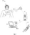
- FIG. 1is a diagram illustrating an exemplary embodiment of a patient monitoring system according to certain aspects of the present disclosure.
- FIG. 2Ais a perspective view of the vital-signs monitor patch of FIG. 1 according to certain aspects of the present disclosure.
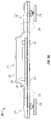
- FIG. 2Bis a cross-section of the vital-signs monitor patch of FIG. 1 according to certain aspects of the present disclosure.
- FIG. 2Cis a functional block diagram illustrating exemplary electronic and sensor components of the vital-signs monitor patch of FIG. 1 according to certain aspects of the present disclosure.
- FIG. 3Ais a functional schematic diagram of the bridge according to certain aspects of the subject disclosure.
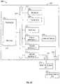
- FIG. 3Bis a functional schematic diagram of an embodiment of the surveillance server according to certain aspects of the present disclosure.
- FIG. 4is a diagram illustrating a store-and-forward system implemented for the vital-signs patch according to certain aspects of the subject disclosure.
- FIG. 5is a diagram illustrating a store-and-forward system implemented for the bridge according to certain aspects of the subject disclosure.
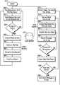
- FIG. 6is a flowchart showing a store-and-forward methodology implemented for the vital-signs patch according to certain aspects of the subject disclosure.
- FIG. 7is a flowchart showing a store-and-forward methodology implemented for the bridge according to certain aspects of the subject disclosure.
- FIGS. 8A and 8Bare diagrams that illustrate the function of a circular data buffer according to certain aspects of the subject disclosure.
- FIGS. 9A and 9Bare diagrams that illustrate a process for managing circular buffer overflow using lost data records according to certain aspects of the subject disclosure.
- Periodic monitoring of patients in a hospitalis desirable at least to ensure that patients do not suffer an un-noticed sudden deterioration in their condition or a secondary injury during their stay in the hospital. It is impractical to provide continuous monitoring by a clinician and cumbersome to connect sensors to a patient, which are then connected to a fixed monitoring instrument by wires. Furthermore, systems that sound an alarm when the measured value exceeds a threshold value may sound alarms so often and in situations that are not truly serious that such alarms are ignored by clinicians.
- heart rate monitorWidely sold for use in exercise and physical training, heart rate monitors may comprise a torso band in which are embedded two electrodes held against the skin and a small electronics package. Such heart rate monitors can communicate wirelessly to other equipment such as a small device that is worn like a wristwatch and that can transfer data wirelessly to a personal computer (PC).
- PCpersonal computer
- ContinuousMonitoring of patients that is referred to as “continuous” is frequently periodic, in that measurements are taken at intervals. In many cases, the process to make a single measurement takes a certain amount of time, such that even back-to-back measurements produce values at an interval equal to the time that it takes to make the measurement.
- a sequence of repeated measurementscan be considered to be “continuous” when the vital sign is not likely to change an amount that is of clinical significance within the interval between measurements. For example, a measurement of blood pressure every 10 minutes may be considered “continuous” if it is considered unlikely that a patient's blood pressure can change by a clinically significant amount within 10 minutes.
- the interval appropriate for measurements to be considered continuousmay depend on a variety of factors including the type of injury or treatment and the patient's medical history. Compared to intervals of 4-8 hours for manual vital sign measurement in a hospital, measurement intervals of 30 minutes to several hours may still be considered “continuous.”
- Certain exemplary embodiments of the present disclosureinclude a system that comprises a vital-signs monitor patch that is attached to the patient, and a bridge that communicates with monitor patches and links them to a central server that processes the data, where the server can send data and alarms to a hospital system according to algorithms and protocols defined by the hospital.
- the construction of the vital-signs monitor patchis described according to certain aspects of the present disclosure.
- the patchmay be worn continuously for a period of time that may be several days, as is described in the following disclosure, it is desirable to encapsulate the components of the patch such that the patient can bathe or shower and engage in their normal activities without degradation of the patch function.
- An exemplary configuration of the construction of the patch to provide a hermetically sealed enclosure about the electronicsis disclosed.
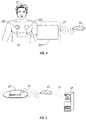
- FIG. 1discloses a vital sign monitoring system according to certain embodiments of the present disclosure.
- the vital sign monitoring system 12includes vital-signs monitor patch 20 , bridge 40 , and surveillance server 60 that can send messages or interact with peripheral devices exemplified by mobile device 90 and workstation 100 .
- Monitor patch 20resembles a large adhesive bandage and is applied to a patient 10 when in use. It is preferable to apply the monitor patch 20 to the upper chest of the patient 10 although other locations may be appropriate in some circumstances. Monitor patch 20 incorporates one or more electrodes (not shown) that are in contact with the skin of patient 10 to measure vital-signs such as cardiac pulse rate and respiration rate. Monitor patch 20 also may include other sensors such as an accelerometer, a temperature sensor, or an oxygen saturation sensor to measure other characteristics associated with the patient. These other sensors may be internal to the monitor patch 20 or external sensors that are operably connected to the monitor patch 20 via a cable or wireless connection. Monitor patch 20 also includes a wireless transmitter that can both transmit and receive signals.
- This transmitteris preferably a short-range, low-power radio frequency (RF) device operating in one of the unlicensed radio bands.
- RFradio frequency
- One band in the United States (US)is, for example, centered at 915 MHz and designated for industrial, scientific and medical (ISM) purposes.
- An example of an equivalent band in the European Union (EU)is centered at 868 MHz.
- Other frequencies of operationmay be possible dependent upon the International Telecommunication Union (ITU), local regulations and interference from other wireless devices.
- Surveillance server 60may be a standard computer server connected to the hospital communication network and preferably located in the hospital data center or computer room, although other locations may be employed.
- the server 60stores and processes signals related to the operation of the patient monitoring system 12 disclosed herein including the association of individual monitor patches 20 with patients 10 and measurement signals received from multiple monitor patches 20 .
- the server 60is able to monitor the monitor patches 20 for multiple patients 10 .
- Bridge 40is a device that connects, or “bridges”, between monitor patch 20 and server 60 .
- Bridge 40communicates with monitor patch 20 over communication link 30 operating, in these exemplary embodiments, at approximately 915 MHz and at a power level that enables communication link 30 to function up to a distance of approximately 10 meters. It is preferable to place a bridge 40 in each room and at regular intervals along hallways of the healthcare facility where it is desired to provide the ability to communicate with monitor patches 20 .
- Bridge 40also is able to communicate with server 60 over network link 50 using any of a variety of computer communication systems including hardwired and wireless Ethernet using protocols such as 802.11a/b/g or 802.3af. As the communication protocols of communication link 30 and network link 50 may be very different, bridge 40 provides data buffering and protocol conversion to enable bidirectional signal transmission between monitor patch 20 and server 60 .
- the monitor patch 20may engage in direct wireless communication with the server 60 .
- the server 60itself or a wireless modem connected to the server 60 may include a wireless communication system to receive data from the monitor patch 20 .
- a monitor patch 20is applied to a patient 10 by a clinician when it is desirable to continuously monitor basic vital signs of patient 10 while patient 10 is, in this embodiment, in a hospital.
- Monitor patch 20is intended to remain attached to patient 10 for an extended period of time, for example, up to 5 days in certain embodiments, limited by the battery life of monitor patch 20 .
- monitor patch 20is disposable when removed from patient 10 .
- Server 60executes analytical protocols on the measurement data that it receives from monitor patch 20 and provides this information to clinicians through external workstations 100 , preferably personal computers (PCs), laptops, or smart phones, over the hospital network 70 .
- Server 60may also send messages to mobile devices 90 , such as cell phones or pagers, over a mobile device link 80 if a measurement signal exceeds specified parameters.
- Mobile device link 80may include the hospital network 70 and internal or external wireless communication systems that are capable of sending messages that can be received by mobile devices 90 .
- FIG. 2Ais a perspective view of the vital-signs monitor patch 20 shown in FIG. 1 according to certain aspects of the present disclosure.
- the monitor patch 20includes component carrier 23 comprising a central segment 21 and side segments 22 on opposing sides of the central segment 21 .
- the central segment 21is substantially rigid and includes a circuit assembly ( 24 , FIG. 28 ) having electronic components and a battery mounted to a rigid printed circuit board (PCB).
- the side segments 22are flexible and include a flexible conductive circuit ( 26 , FIG. 28 ) that connect the circuit assembly 24 to electrodes 28 disposed at each end of the monitor patch 20 , with side segment 22 on the right shown as being bent upwards for purposes of illustration to make one of the electrodes 28 visible in this view.
- FIG. 2Bis a cross-sectional view of the vital-signs patch 20 shown in FIGS. 1 and 2A according to certain aspects of the present disclosure.
- the circuit assembly 24 and flexible conductive circuit 26 described abovecan be seen herein.
- the flexible conductive circuit 26operably connects the circuit assembly 24 to the electrodes 28 .
- Top and bottom layers 23 and 27form a housing 25 that encapsulate circuit assembly 28 to provide a water and particulate harrier as well as mechanical protection.
- the term ‘hermetic’implies that the rate of transmission of moisture through the seal is substantially the same as through the material of the layers that are sealed to each other, and further implies that the size of particulates that can pass through the seal are below the size that can have a significant effect on circuit assembly 24 .
- Flexible conductive circuit 26passes through portions of sealing areas 29 and the seal between layers 23 and 27 is maintained by sealing of layers 23 and 27 to flexible circuit assembly 28 .
- the layers 23 and 27are thin and flexible, as is the flexible conductive circuit 26 , allowing the side segment 22 of the monitor patch 20 between the electrodes 28 and the circuit assembly 24 to bend as shown in FIG. 2A .
- FIG. 2Cis a functional block diagram 200 illustrating exemplary electronic and sensor components of the monitor patch 20 of FIG. 1 according to certain aspects of the present disclosure.
- the block diagram 200shows a processing and sensor interface module 201 and external sensors 232 , 234 connected to the module 201 .
- the module 201includes a processor 202 , a wireless transceiver 207 having a receiver 206 and a transmitter 209 , a memory 210 , a first sensor interface 212 , a second sensor interface 214 , a third sensor interface 216 , and an internal sensor 236 connected to the third sensor interface 216 .
- the first and second sensor interfaces 212 and 214are connected to the first and second external sensors 232 , 234 via first and second connection ports 222 , 224 , respectively.
- some or all of the aforementioned components of the module 201 and other componentsare mounted on a PCB.
- Each of the sensor interfaces 212 , 214 , 216can include one or more electronic components that are configured to generate an excitation signal or provide DC power for the sensor that the interface is connected to and/or to condition and digitize a sensor signal from the sensor.
- the sensor interfacecan include a signal generator for generating an excitation signal or a voltage regulator for providing power to the sensor.
- the sensor interfacecan further include an amplifier for amplifying a sensor signal from the sensor and an analog-to-digital converter for digitizing the amplified sensor signal.
- the sensor interfacecan further include a filter (e.g., a low-pass or bandpass filter) for filtering out spurious noises (e.g., a 60 Hz noise pickup).
- the processor 202is configured to send and receive data (e.g., digitized signal or control data) to and from the sensor interfaces 212 , 214 , 216 via a bus 204 , which can be one or more wire traces on the PCB.
- a bus communication topologyis used in this embodiment, some or all communication between discrete components can also be implemented as direct links without departing from the scope of the present disclosure.
- the processor 202may send data representative of an excitation signal to the sensor excitation signal generator inside the sensor interface and receive data representative of the sensor signal from the sensor interface, over either a bus or direct data links between processor 202 and each of sensor interface 212 , 214 , and 216 .
- the processor 202is also capable of communication with the receiver 206 and the transmitter 209 of the wireless transceiver 207 via the bus 204 .
- the processor 202using the transmitter and receiver 209 , 206 can transmit and receive data to and from the bridge 40 .
- the transmitter 209includes one or more of a RF signal generator (e.g., an oscillator), a modulator (a mixer), and a transmitting antenna; and the receiver 206 includes a demodulator (a mixer) and a receiving antenna which may or may not be the same as the transmitting antenna.
- the transmitter 209may include a digital-to-analog converter configured to receive data from the processor 202 and to generate a base signal; and/or the receiver 206 may include an analog-to-digital converter configured to digitize a demodulated base signal and output a stream of digitized data to the processor 202 .
- the radiomay comprise a direct sequence radio, a software-defined radio, or an impulse spread spectrum radio.
- the processor 202may include a general-purpose processor or a specific-purpose processor for executing instructions and may further include a memory 219 , such as a volatile or non-volatile memory, for storing data and/or instructions for software programs.
- the instructionswhich may be stored in a memory 219 and/or 210 , may be executed by the processor 202 to control and manage the wireless transceiver 207 , the sensor interfaces 212 , 214 , 216 , as well as to provide other communication and processing functions.
- the processor 202may be a general-purpose microprocessor, a microcontroller, a Digital Signal Processor (DSP), an Application Specific Integrated Circuit (ASIC), a Field Programmable Gate Array (FPGA), a Programmable Logic Device (PLD), a controller, a state machine, gated logic, discrete hardware components, or any other suitable device or a combination of devices that can perform calculations or other manipulations of information.
- DSPDigital Signal Processor
- ASICApplication Specific Integrated Circuit
- FPGAField Programmable Gate Array
- PLDProgrammable Logic Device
- controllera state machine, gated logic, discrete hardware components, or any other suitable device or a combination of devices that can perform calculations or other manipulations of information.
- Informationsuch as program instructions, data representative of sensor readings, preset alarm conditions, threshold limits, may be stored in a computer or in a processor readable medium such as a memory internal to the processor 202 (e.g., the memory 219 ) or a memory external to the processor 202 (e.g., the memory 210 ), such as a Random Access Memory (RAM), a flash memory, a Read Only Memory (ROM), a Programmable Read-Only Memory (PROM), an Erasable PROM (EPROM), registers, a hard disk, a removable disk, or any other suitable storage device.
- RAMRandom Access Memory
- ROMRead Only Memory
- PROMErasable PROM
- registersa hard disk, a removable disk, or any other suitable storage device.
- the internal sensor 236can be one or more sensors configured to measure certain properties of the processing and sensor interface module 201 , such as a board temperature sensor thermally coupled to a PCB. In other embodiments, the internal sensor 236 can be one or more sensors configured to measure certain properties of the patient 10 , such as a motion sensor (e.g., an accelerometer) for measuring the patient's motion or position with respect to gravity.
- a motion sensore.g., an accelerometer
- the external sensors 232 , 234can include sensors and sensing arrangements that are configured to produce a signal representative of one or more vital signs of the patient to which the monitor patch 20 is attached.
- the first external sensor 232can be a set of sensing electrodes that are affixed to an exterior surface of the monitor patch 20 and configured to be in contact with the patient for measuring the patient's respiratory rate
- the second external sensor 234can include a temperature sensing element (e.g., a thermocouple or a thermistor or resistive thermal device (RTD)) affixed, either directly or via an interposing layer, to skin of the patient 10 for measuring the patient's body temperature.
- one or more of the external sensors 232 , 234 or one or more additional external sensorscan measure other vital signs of the patient, such as blood pressure, pulse rate, or oxygen saturation.
- FIG. 3Ais a functional block diagram illustrating exemplary electronic components of bridge 40 of FIG. 1 according to one aspect of the subject disclosure.
- Bridge 40includes a processor 310 310 , radio 320 having a receiver 322 and a transmitter 324 , radio 330 having a receiver 332 and a transmitter 334 , memory 340 , display 345 , and network interface 350 having a wireless interface 352 and a wired interface 354 .
- some or all of the aforementioned components of module 300may be integrated into single devices or mounted on PCBs.
- Processor 310is configured to send data to and receive data from receiver 322 and transmitter 324 of radio 320 , receiver 332 and transmitter 334 of radio 330 and wireless interface 352 and wired interface 354 of network interface 350 via bus 314 .
- transmitters 324 and 334may include a radio frequency signal generator (oscillator), a modulator, and a transmitting antenna
- the receivers 322 and 332may include a demodulator and antenna which may or may not be the same as the transmitting antenna of the radio.
- transmitters 324 and 334may include a digital-to-analog converter configured to convert data received from processor 310 and to generate a base signal, while receivers 322 and 332 may include analog-to-digital converters configured to convert a demodulated base signal and sent a digitized data stream to processor 310 .
- Processor 310may include a general-purpose processor or a specific-purpose processor for executing instructions and may further include a memory 312 , such as a volatile or non-volatile memory, for storing data and/or instructions for software programs.
- the instructionswhich may be stored in memories 312 or 340 , may be executed by the processor 310 to control and manage the transceivers 320 , 330 , and 350 as well as provide other communication and processing functions.
- Processor 310may be a general-purpose microprocessor, a microcontroller, a Digital Signal Processor (DSP), an Application Specific Integrated Circuit (ASIC), a Field Programmable Gate Array (FPGA), a Programmable Logic Device (PLD), a controller, a state machine, gated logic, discrete hardware components, or any other suitable device or a combination of devices that can perform calculations or other manipulations of information.
- DSPDigital Signal Processor
- ASICApplication Specific Integrated Circuit
- FPGAField Programmable Gate Array
- PLDProgrammable Logic Device
- controllera state machine, gated logic, discrete hardware components, or any other suitable device or a combination of devices that can perform calculations or other manipulations of information.
- RAMRandom Access Memory
- ROMRead Only Memory
- PROMProgrammable Read Only Memory
- EPROMErasable Programmable Read Only Memory
- registersa hard disk, a removable disk, a Solid State Memory (SSD), or any other suitable storage device.
- Memory 312 or 340can also store a list or a database of established communication links and their corresponding characteristics (e.g., signal levels) between the bridge 40 and its related monitor patches 20 .
- the memory 340 external to the processor 310includes such a database 342 ; alternatively, the memory 312 internal to the processor 310 may include such a database.
- FIG. 3Bis a functional block diagram illustrating exemplary electronic components of server 60 of FIG. 1 according to one aspect of the subject disclosure.
- Server 60includes a processor 360 , memory 370 , display 380 , and network interface 390 having a wireless interface 392 and a wired interface 394 .
- Processor 360may include a general-purpose processor or a specific-purpose processor for executing instructions and may further include a memory 362 , such as a volatile or non-volatile memory, for storing data and/or instructions for software programs.
- the instructionswhich may be stored in memories 362 or 370 , may be executed by the processor 360 to control and manage the wireless and wired network interfaces 392 , 394 as well as provide other communication and processing functions.
- Processor 360may be a general-purpose microprocessor, a microcontroller, a Digital Signal Processor (DSP), an Application Specific Integrated Circuit (ASIC), a Field Programmable Gate Array (FPGA), a Programmable Logic Device (PLD), a controller, a state machine, gated logic, discrete hardware components, or any other suitable device or a combination of devices that can perform calculations or other manipulations of information.
- DSPDigital Signal Processor
- ASICApplication Specific Integrated Circuit
- FPGAField Programmable Gate Array
- PLDProgrammable Logic Device
- controllera state machine, gated logic, discrete hardware components, or any other suitable device or a combination of devices that can perform calculations or other manipulations of information.
- RAMRandom Access Memory
- ROMRead Only Memory
- PROMProgrammable Read Only Memory
- EPROMErasable Programmable Read Only Memory
- registersa hard disk, a removable disk, a Solid State Memory (SSD), or any other suitable storage device.
- Memory 362 or 370can also store a database of communication links and their corresponding characteristics (e.g., signal levels) between monitor patches 20 and bridges 40 .
- the memory 370 external to the processor 360includes such a database 372 ; alternatively, the memory 362 internal to the processor 360 may include such a database.
- FIG. 4graphically illustrates a “store-and-forward” data transfer of vital sign measurements taken by the vital-sign patch 20 from, in this example, electrodes 232 by module 201 of patch 20 and forwarded from patch 20 to bridge 40 .
- Some existing wireless devices that monitor vital signssuch as cardiac pulse broadcast each measurement at the time the measurement was taken without confirmation that the data was received intact.
- measurementsare taken at regular intervals at the patient 10 while the vital sign signal transfer from patch 20 to bridge 40 over communication link 30 is at irregular intervals which are controlled by bridge 40 and which are not synchronized with the measurement intervals.
- FIG. 4graphically illustrates a “store-and-forward” data transfer of vital sign measurements taken by the vital-sign patch 20 from, in this example, electrodes 232 by module 201 of patch 20 and forwarded from patch 20 to bridge 40 .
- FIG. 5graphically illustrates the “store-and-forward” transfer of vital sign signals received by bridge 40 from patch 20 over communication link 30 and then forwarded to server 60 over network link 50 .
- server 60There is no requirement that the transfer of data from bridge 40 to server 60 over network link 50 be synchronized with the transfer of data from patch 20 over communication link 30 to bridge 40 .
- FIG. 6is a flowchart that illustrates an exemplary store-and-forward methodology as implemented for the vital-signs patch according to certain embodiments of the present disclosure.
- FIG. 6illustrates an exemplary store-and-forward methodology as implemented for the vital-signs patch according to certain embodiments of the present disclosure.
- the process of FIG. 6starts at step 450 when patch 20 is applied to a patient and activated.
- the sensorwill be a pair of electrodes 28 ( FIG. 2B ) and the vital sign of interest is respiration, although patch 20 may have other sensors and may be measuring other vital signs instead of or in addition to respiration.
- Processor 202 of patch 20takes a voltage measurement from the electrodes in step 452 and the measurement and the time at which the measurement was taken are stored in memory 202 in step 454 . As determining the rate of respiration requires a series of measurements that are evaluated as a set, step 456 branches back to step 452 at this point.
- step 456will branch to step 458 where the data is analyzed, in this example to find two successive peaks in the measurements, and the respiration rate is calculated, in this example, from the time interval between these peaks, in step 460 .
- This calculated valueis converted to a data record in step 462 , in this example, by storing a record sequence number, the time of the second peak value, and the calculated respiration rate in a defined data structure, and in step 464 the data record is stored in data buffer 470 located, in this example, in memory 202 .
- a second process of steps 472 through 488is being independently executed.
- Patch 20is listening with receiver 206 for a signal from bridge 40 .
- this second processis initiated.
- Patch processor 20will retrieve the oldest data record, as indicated in this example by the sequence number assigned in the first process, from data buffer 470 in step 474 .
- the data recordis converted in step 476 to a vital-sign signal according to the communication protocol of link 30 and transmitted to bridge 40 in step 480 .
- Patch 20then waits for a signal from bridge 40 as to whether the transmission was successful.
- step 482will branch back to step 478 and resend the same vital-sign signal. If the message from the bridge is that the transmission was successful, step 482 will bridge to step 484 where the data record associated with the transmission, which is the oldest record in data buffer 470 , is erased. If more data records are available to transmit, step 486 branches back to step 474 to process the next-oldest record. If there are no more records ready to transmit, patch 20 sends a ‘done” message to bridge 40 and returns to step 472 to await the next ‘upload’ command.
- a patch 20may lose communication with bridge 40 , for example, when a patient travels to a part of the hospital where there are no bridges 40 . If a patch 20 is out of communication with any bridge 40 for a period of time exceeding the measurement interval of step 452 , then patch 20 will continue to make and store vital sign measurements following the loop 452 - 456 - 464 - 452 . In some embodiments, patch 20 may comprise enough memory to hold several hours of vital sign measurements.
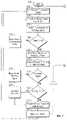
- FIG. 7is a flowchart that illustrates an embodiment of the store-and-forward methodology as implemented for the bridge.
- FIG. 7illustrates an embodiment of the store-and-forward methodology as implemented for the bridge.
- the processstarts at step 500 and proceeds to step 502 where bridge 40 sends an ‘upload’ command to patch 20 .
- Bridge 40then receives a vital-sign signal from patch 20 in step 504 .
- the vital-sign signalis structured as a data packet that includes a packet identification value and a data integrity value.
- the packet identification valuemay be unique over some duration of activity such that the system can determine whether a received data packet is a duplicate of a packet previously received (i.e. two packets have the same packet identification value) or whether a data packet has been missed (i.e. there is a gap in the sequence of packet identification values).
- the packet identification valuemay be a numeric string composed of the serial number of patch 20 followed by a sequence number where the sequence number is, in this example, incremented by one for each new packet that is sent. If a packet is retransmitted, the same sequence number is used as was used for the initial transmission.
- the data integrity valuemay be a Cyclic Redundancy Check (CRC) value or other error-detection value that is used to verify that the packet has been received without corruption at an acceptable level of certainty.
- CRCCyclic Redundancy Check
- Use of a CRC value to verify the integrity of a data signalis well known in the art. As a data integrity check of this type may not provide 100% certainty that an error in transmission has not occurred, other types of error-detection algorithms may be used to provide a higher degree of assurance that the signal has not been corrupted in transit.
- step 506bridge 40 analyzes the data integrity of the vital-sign signal data packet using the CRC value. If an error in the data packet is detected, step 508 branches to step 510 where bridge 40 sends a ‘resend’ command to patch 20 and the process reverts to step 504 . If no error is detected in the vital-sign signal, step 508 branches to step 512 where bridge 40 sends a “good transmission” signal to patch 20 and proceeds to step 514 where the message sequence is evaluated. If the sequence number indicates that this vital-sign signal is a duplicate of a previous successfully-received signal, step 516 branches to step 518 where this signal is discarded and the process reverts to step 502 .
- step 520branches to step 522 which logs the gap. Regardless of a gap, the process then reaches step 524 where the vital-sign signal is converted to a data record and stored in step 526 in data buffer 530 .
- step 532bridge 40 is listening for an upload command from server 60 .
- This stepmay be implemented in a number of configurations according to the protocol of network link 50 , some of which include actions by the bridge to determine whether it is appropriate to initiate a transmission, without departing from the scope of the subject disclosure.
- the processmoves to step 534 where the oldest data record is retrieved from data buffer 530 .
- the data recordis converted to a vital-signs signal according to the protocol of network link 50 in step 536 and transmitted to server 60 in step 538 .
- Bridge 40then waits for a signal from the server in step 540 as to whether the transmission was successfully received. If the transmission was not successfully received, step 542 branches back to step 538 and resends the same signal. If the signal was successfully received, step 542 branches to step 544 and erases the oldest data record, which was associated with the signal just sent. If there are more data records available to transmit, step 546 branches to step 534 and retrieves the next-oldest record. If there are no more records ready to transmit, step 546 branches to step 548 and sends a ‘done’ message to the server, according to the protocol of network link 50 , and returns to step 532 to await initiation of the next upload sequence.
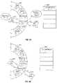
- FIGS. 8A and 8Billustrate the configuration and use of a circular data buffer 801 in certain embodiments of the present disclosure.
- data buffer SOL located in memory 202is able to store 16 data records but a data buffer may be of any size, limited only by the available storage capacity of the device. Circular data buffers are especially advantageous where the storage capacity is limited, such as in an embedded microprocessor system.
- the depiction of data buffer 801 as a circle of storage locationsis intended to assist in understanding, as the designation of the storage locations has no physical significance.
- data recordsare stored in sequential locations in data buffer 801 and each data record has a number associated with the sequence in which the records were stored.
- the oldest data recordis number “N” and the latest record is “N+3”.
- Two pointersare associated with data buffer 801 .
- the ‘next write’ pointer 810indicates which storage location of data buffer 801 will be used for the next data record to be received.
- the ‘next read’ pointer 805indicates the storage location of data buffer 801 that contains the oldest data record that is the data record that will be transmitted first.
- the number of records from the ‘next read’ pointer 805 to the ‘next write’ pointer 810indicates the amount of data currently stored in data buffer 801 . In this example, there are 4 records in data buffer 801 , which has a capacity of 16, so the buffer is 25% full.
- New data recordsmay be received asynchronously from data records being read. For example, a new data record may be received at a fixed time interval while data records may be read in groups at irregular intervals.
- data buffer 801will become increasingly full.
- data buffer 801will become increasingly empty until there are no data records stored in data buffer 801 . It is desirable to select the size of data buffer 801 to be large enough to store the largest number of data records that might accumulate.
- circular data buffer 801is full. This may occur when there is an interruption in the reading of data records for a period of time longer than anticipated by the software programmer.
- the oldest existing data recordis “N+1” and the last record stored is “N+16”.
- the ‘next read’ pointer 810 and ‘next write’ pointer 805both indicate the same record.
- the next recordis received, it would be stored in the same location as currently occupied by record “N+1”, erasing record “N+1” resulting in loss of the data in data record “N+1”. This is termed “circular buffer overflow.”
- FIGS. 9A and 9Bdescribe an exemplary embodiment of a method of handling circular buffer overflow according to certain embodiments of the present disclosure.
- data record “N+17”has been received but is not yet written into data buffer 801 .
- the processorfirst reads data record “N+1” and extracts key information such as the time of the reading and whether the reading is within limits.
- This key informationis stored as a “lost data record” in array 820 which occupies a separate area of memory 202 .
- the lost data recordis much smaller than the data record from which it is created, possibly as small as a single bit depending on how much information the programmer wishes to retain.
- FIG. 9Billustrates the configuration of the buffer at the end of the storage operation, with the oldest record in the buffer now being data record “N+2” and the newest record being data record “N+17”, both the ‘next write’ pointer 810 and ‘next read’ pointer 805 indicating the buffer location occupied by data record “N+2”, and with a separate lost data record “N+1” stored in the first location of array 820 .
- Alternate forms of a lost data recordmay be a single register that stores the number of data records that have been overwritten, or a pair of registers that store the number of overwritten records that were within limits and that exceeded limits.
- the advantage of these alternate methodsis that they occupy a very small and fixed amount of memory while being able to handle a relatively large number of lost data records, up to the allocated size of the registers.
- the disadvantageis that the amount of information retained regarding the values of the lost data records is very small.
- the disclosed embodiments of the vital-signs monitor patchprovide a mobile solution to monitoring the vital signs of a patient.
- the design of the vital-signs monitor patchfrees nurses, or other caregivers, from the task of repetitively measuring the vital signs of their patients, allowing the caregivers to spend more time on other duties.
- the ability to continuously monitor a patient's vital signs using a monitor patch, together with the rest of the patient monitoring system,increases the ability of the nurse to respond quickly to a sudden change in a patient's condition, resulting in improved care for the patient.
- the store-and-forward capability of the patchenables the patch to accumulate vital-sign measurements while the patient is out of range of a bridge and, up to certain interval of time out of communication, transfer this data to the rest of the patient monitoring system without loss of data taken during the time out of communication. Furthermore, in cases where the patient is out of range of a bridge for a period of time exceeding the storage limits of the patch, a reduced amount of information related to the oldest measurements is retained and, when the patch regains a communication link to the rest of the patient monitoring system, information is sent to the system regarding the lost measurements in addition to the complete records of the latest measurements.
- the datacan be retained by the patch until the bridge confirms that the data was received intact and if a data transfer was corrupted, the same data can be resent. This retention of data until receipt is confirmed increases the reliability of the communication link between the patch and bridge.
- the store-and-forward capability of the bridgeenables the bridge to receive data from each patch to which the bridge is assigned at times determined by the bridge.
- the time at which this same information is transferred from the bridge to the servercan be selected by the server to optimize other characteristics of the system, such as load management of the server-to-bridge communication link.
- This decoupling of the timing of the patch-to-bridge data transfer from the bridge-to-server data transferincreases the reliability of the end-to-end linkage from a patch to the server as the transfer over each link can be verified without impact to the next link of the transfer chain.
- topshould be understood as referring to an arbitrary frame of reference, rather than to the ordinary gravitational frame of reference.
- a top surface, a bottom surface, a front surface, and a rear surfacemay extend upwardly, downwardly, diagonally, or horizontally in a gravitational frame of reference.
- a phrase such as an “aspect”does not imply that such aspect is essential to the subject technology or that such aspect applies to all configurations of the subject technology.
- a disclosure relating to an aspectmay apply to all configurations, or one or more configurations.
- a phrase such as an aspectmay refer to one or more aspects and vice versa.
- a phrase such as an “embodiment”does not imply that such embodiment is essential to the subject technology or that such embodiment applies to all configurations of the subject technology.
- a disclosure relating to an embodimentmay apply to all embodiments, or one or more embodiments.
- a phrase such an embodimentmay refer to one or more embodiments and vice versa.
Landscapes
- Health & Medical Sciences (AREA)
- Engineering & Computer Science (AREA)
- Life Sciences & Earth Sciences (AREA)
- Biomedical Technology (AREA)
- Medical Informatics (AREA)
- General Health & Medical Sciences (AREA)
- Public Health (AREA)
- Physics & Mathematics (AREA)
- Computer Networks & Wireless Communication (AREA)
- Pathology (AREA)
- Veterinary Medicine (AREA)
- Molecular Biology (AREA)
- Surgery (AREA)
- Animal Behavior & Ethology (AREA)
- Biophysics (AREA)
- Heart & Thoracic Surgery (AREA)
- Signal Processing (AREA)
- Physiology (AREA)
- Theoretical Computer Science (AREA)
- Cardiology (AREA)
- Epidemiology (AREA)
- Primary Health Care (AREA)
- Pulmonology (AREA)
- General Engineering & Computer Science (AREA)
- General Physics & Mathematics (AREA)
- General Business, Economics & Management (AREA)
- Business, Economics & Management (AREA)
- Vascular Medicine (AREA)
- Computing Systems (AREA)
- Measuring And Recording Apparatus For Diagnosis (AREA)
Abstract
Description
Claims (20)
Priority Applications (2)
| Application Number | Priority Date | Filing Date | Title |
|---|---|---|---|
| US14/458,147US11311239B2 (en) | 2010-07-27 | 2014-08-12 | System and method for storing and forwarding data from a vital-signs monitor |
| US17/728,883US20220249023A1 (en) | 2010-07-27 | 2022-04-25 | System and method for storing and forwarding data from a vital-signs monitor |
Applications Claiming Priority (2)
| Application Number | Priority Date | Filing Date | Title |
|---|---|---|---|
| US12/844,780US8814792B2 (en) | 2010-07-27 | 2010-07-27 | System and method for storing and forwarding data from a vital-signs monitor |
| US14/458,147US11311239B2 (en) | 2010-07-27 | 2014-08-12 | System and method for storing and forwarding data from a vital-signs monitor |
Related Parent Applications (1)
| Application Number | Title | Priority Date | Filing Date |
|---|---|---|---|
| US12/844,780ContinuationUS8814792B2 (en) | 2010-07-27 | 2010-07-27 | System and method for storing and forwarding data from a vital-signs monitor |
Related Child Applications (1)
| Application Number | Title | Priority Date | Filing Date |
|---|---|---|---|
| US17/728,883ContinuationUS20220249023A1 (en) | 2010-07-27 | 2022-04-25 | System and method for storing and forwarding data from a vital-signs monitor |
Publications (2)
| Publication Number | Publication Date |
|---|---|
| US20140350362A1 US20140350362A1 (en) | 2014-11-27 |
| US11311239B2true US11311239B2 (en) | 2022-04-26 |
Family
ID=45527415
Family Applications (3)
| Application Number | Title | Priority Date | Filing Date |
|---|---|---|---|
| US12/844,780Active2033-03-28US8814792B2 (en) | 2010-07-27 | 2010-07-27 | System and method for storing and forwarding data from a vital-signs monitor |
| US14/458,147Active2032-06-04US11311239B2 (en) | 2010-07-27 | 2014-08-12 | System and method for storing and forwarding data from a vital-signs monitor |
| US17/728,883PendingUS20220249023A1 (en) | 2010-07-27 | 2022-04-25 | System and method for storing and forwarding data from a vital-signs monitor |
Family Applications Before (1)
| Application Number | Title | Priority Date | Filing Date |
|---|---|---|---|
| US12/844,780Active2033-03-28US8814792B2 (en) | 2010-07-27 | 2010-07-27 | System and method for storing and forwarding data from a vital-signs monitor |
Family Applications After (1)
| Application Number | Title | Priority Date | Filing Date |
|---|---|---|---|
| US17/728,883PendingUS20220249023A1 (en) | 2010-07-27 | 2022-04-25 | System and method for storing and forwarding data from a vital-signs monitor |
Country Status (2)
| Country | Link |
|---|---|
| US (3) | US8814792B2 (en) |
| WO (1) | WO2012015844A2 (en) |
Families Citing this family (43)
| Publication number | Priority date | Publication date | Assignee | Title |
|---|---|---|---|---|
| CA2786524C (en)* | 2010-01-11 | 2019-07-09 | Card Guard Scientific Survival Ltd. | An adhesive bandage and a method for controlling patient information |
| US11881307B2 (en) | 2012-05-24 | 2024-01-23 | Deka Products Limited Partnership | System, method, and apparatus for electronic patient care |
| US20110313789A1 (en) | 2010-01-22 | 2011-12-22 | Deka Products Limited Partnership | Electronic patient monitoring system |
| US11164672B2 (en) | 2010-01-22 | 2021-11-02 | Deka Products Limited Partnership | System and apparatus for electronic patient care |
| US11244745B2 (en) | 2010-01-22 | 2022-02-08 | Deka Products Limited Partnership | Computer-implemented method, system, and apparatus for electronic patient care |
| US11210611B2 (en) | 2011-12-21 | 2021-12-28 | Deka Products Limited Partnership | System, method, and apparatus for electronic patient care |
| US10911515B2 (en) | 2012-05-24 | 2021-02-02 | Deka Products Limited Partnership | System, method, and apparatus for electronic patient care |
| US10242159B2 (en) | 2010-01-22 | 2019-03-26 | Deka Products Limited Partnership | System and apparatus for electronic patient care |
| US10453157B2 (en) | 2010-01-22 | 2019-10-22 | Deka Products Limited Partnership | System, method, and apparatus for electronic patient care |
| EP2571420A4 (en) | 2010-05-21 | 2018-04-18 | Medicomp, INC. | Retractable multi-use cardiac monitor |
| US9585584B2 (en) | 2010-05-21 | 2017-03-07 | Medicomp, Inc. | Physiological signal monitor with retractable wires |
| US9585620B2 (en) | 2010-07-27 | 2017-03-07 | Carefusion 303, Inc. | Vital-signs patch having a flexible attachment to electrodes |
| US9017255B2 (en) | 2010-07-27 | 2015-04-28 | Carefusion 303, Inc. | System and method for saving battery power in a patient monitoring system |
| US8814792B2 (en) | 2010-07-27 | 2014-08-26 | Carefusion 303, Inc. | System and method for storing and forwarding data from a vital-signs monitor |
| US9055925B2 (en) | 2010-07-27 | 2015-06-16 | Carefusion 303, Inc. | System and method for reducing false alarms associated with vital-signs monitoring |
| US10563681B2 (en) | 2011-12-21 | 2020-02-18 | Deka Products Limited Partnership | System, method, and apparatus for clamping |
| US12196364B2 (en) | 2011-12-21 | 2025-01-14 | DEKA Research Products Limited Partnership | System, method, and apparatus for clamping |
| CN104582564B (en)* | 2012-09-03 | 2017-03-15 | 株式会社日立制作所 | Biological signal measuring device and biosignal measurement set |
| US9329667B2 (en)* | 2012-11-21 | 2016-05-03 | Completecover, Llc | Computing device employing a proxy processor to learn received patterns |
| US20140171751A1 (en)* | 2012-12-19 | 2014-06-19 | Robert L. Sankman | Electronic bio monitoring patch |
| EP3021742A4 (en)* | 2013-07-18 | 2017-03-01 | Nuline Sensors, LLC | Medical data acquisition systems and methods for monitoring and diagnosis |
| JP6240448B2 (en)* | 2013-09-25 | 2017-11-29 | テルモ株式会社 | Biological information management apparatus, biological information management system, and biological information management method |
| US9756454B1 (en) | 2014-05-19 | 2017-09-05 | Silent Beacon, Llc | Portable wearable primary device which communciates data to secondary device that is in communication with multiple networks and related communication systems |
| US10524711B2 (en) | 2014-06-09 | 2020-01-07 | International Business Machines Corporation | Cognitive event predictor |
| US20160007910A1 (en) | 2014-07-10 | 2016-01-14 | International Business Machines Corporation | Avoidance of cognitive impairment events |
| KR20160143102A (en) | 2015-06-04 | 2016-12-14 | 삼성전자주식회사 | Portable biological information measuring device |
| JP6281532B2 (en)* | 2015-07-13 | 2018-02-21 | トヨタ自動車株式会社 | Electrolyte for metal-air battery and metal-air battery |
| WO2017051010A1 (en)* | 2015-09-24 | 2017-03-30 | Koninklijke Philips N.V. | Automatic sensor identification |
| US10582981B2 (en) | 2016-02-02 | 2020-03-10 | Stryker Corporation | Accessory support and coupling systems for an accessory support |
| US10888281B2 (en) | 2016-05-13 | 2021-01-12 | PercuSense, Inc. | System and method for disease risk assessment and treatment |
| US12184415B2 (en) | 2016-07-25 | 2024-12-31 | Koninklijke Philips N.V. | Robust data transmittal |
| US20180094984A1 (en)* | 2016-10-03 | 2018-04-05 | Akro-Mils, A Division Of Myers Industries, Inc. | Sensing system for bins |
| USD821588S1 (en) | 2017-01-26 | 2018-06-26 | Michael J. Vosch | Electrode patch array |
| USD821587S1 (en) | 2017-01-26 | 2018-06-26 | Michael J. Vosch | Electrode patch array |
| USD907213S1 (en) | 2017-09-18 | 2021-01-05 | Dms-Service Llc | Patch with electrode array |
| US11229361B2 (en)* | 2017-10-17 | 2022-01-25 | Aidan Coen | Health information measurement system |
| USD898202S1 (en) | 2017-11-12 | 2020-10-06 | Dms-Service Llc | Patch with electrode array |
| CN110151150B (en) | 2018-02-12 | 2022-03-29 | 财团法人工业技术研究院 | Physiological sensor device and system, correction method and wearable device |
| EP3701857B1 (en)* | 2019-02-28 | 2023-10-04 | Hill-Rom Services, Inc. | Patient support apparatus having vital signs and sepsis display apparatus |
| WO2021005441A1 (en)* | 2019-07-05 | 2021-01-14 | Raja K N Vijai Shankar | A vital sign measurement system |
| TWI734507B (en) | 2020-06-03 | 2021-07-21 | 豪展醫療科技股份有限公司 | Thermometer |
| USD1039997S1 (en)* | 2020-06-22 | 2024-08-27 | Owlet Baby Care, Inc. | Biological sensor module |
| US20210393202A1 (en) | 2020-06-22 | 2021-12-23 | Owlet Baby Care, Inc. | Monitoring Device |
Citations (243)
| Publication number | Priority date | Publication date | Assignee | Title |
|---|---|---|---|---|
| US3677261A (en) | 1970-04-03 | 1972-07-18 | American Optical Corp | Impedance pneumograph |
| US3805769A (en) | 1971-08-27 | 1974-04-23 | R Sessions | Disposable electrode |
| US3830224A (en) | 1972-12-19 | 1974-08-20 | Vanzetti Infrared Computer Sys | Means for detecting changes in the temperature of the skin |
| US3845757A (en) | 1972-07-12 | 1974-11-05 | Minnesota Mining & Mfg | Biomedical monitoring electrode |
| US4121574A (en) | 1977-04-11 | 1978-10-24 | Medicgraph Systems, Inc. | Method and apparatus for measuring and recording vital signs of a patient |
| US4396020A (en) | 1979-12-21 | 1983-08-02 | National Research Development Corporation | Measurement of basal body temperature |
| US4407295A (en) | 1980-10-16 | 1983-10-04 | Dna Medical, Inc. | Miniature physiological monitor with interchangeable sensors |
| US4490005A (en) | 1982-06-21 | 1984-12-25 | Minnesota Mining And Manufacturing Company | Electrical connector |
| US4527087A (en) | 1981-09-03 | 1985-07-02 | Tokyo Shibaura Denki Kabushiki Kaisha | Fluorescent lamp |
| US4530366A (en) | 1981-12-01 | 1985-07-23 | Ares N.V. Amsterdam Nl, Swiss Branch | Electronic instrument for the control and treatment of infertility in women |
| US4539996A (en) | 1980-01-23 | 1985-09-10 | Minnesota Mining And Manufacturing Company | Conductive adhesive and biomedical electrode |
| US4541734A (en) | 1982-06-24 | 1985-09-17 | Terumo Kabushiki Kaisha | Electronic clinical thermometer, and method of measuring body temperature |
| US4554924A (en) | 1980-01-23 | 1985-11-26 | Minnesota Mining And Manufacturing Company | Conductive adhesive and biomedical electrode |
| JPS613019A (en) | 1984-06-18 | 1986-01-09 | Omron Tateisi Electronics Co | Electronic clinical thermometer |
| US4589420A (en)* | 1984-07-13 | 1986-05-20 | Spacelabs Inc. | Method and apparatus for ECG rhythm analysis |
| US4640289A (en) | 1983-11-14 | 1987-02-03 | Minnesota Mining And Manufacturing Company | Biomedical electrode |
| US4686998A (en) | 1985-11-12 | 1987-08-18 | Mediscan Research Limited | Patient temperature and heartbeat rate monitoring system |
| US4708146A (en) | 1986-08-06 | 1987-11-24 | Spacelabs, Inc. | Apparatus and method for impedance pneumography |
| US4715382A (en) | 1986-08-01 | 1987-12-29 | Minnesota Mining And Manufacturing Company | Flat biomedical electrode with reuseable lead wire |
| US4765340A (en) | 1985-04-02 | 1988-08-23 | Minolta Camera Kabushiki Kaisha | Apnea detector |
| US4771713A (en) | 1985-05-20 | 1988-09-20 | Kinzenbaw Jon E | Row crop planter convertible between narrow and wide row spacing |
| US4838273A (en) | 1979-04-30 | 1989-06-13 | Baxter International Inc. | Medical electrode |
| US4846185A (en) | 1987-11-25 | 1989-07-11 | Minnesota Mining And Manufacturing Company | Bioelectrode having a galvanically active interfacing material |
| US4848353A (en) | 1986-09-05 | 1989-07-18 | Minnesota Mining And Manufacturing Company | Electrically-conductive, pressure-sensitive adhesive and biomedical electrodes |
| WO1990012606A2 (en) | 1989-04-10 | 1990-11-01 | Baxter International Inc. | iRE-SLIT INJECTION SITE AND TAPERED CANNULA |
| US4967765A (en) | 1988-07-28 | 1990-11-06 | Bsd Medical Corporation | Urethral inserted applicator for prostate hyperthermia |
| US5012810A (en) | 1988-09-22 | 1991-05-07 | Minnesota Mining And Manufacturing Company | Biomedical electrode construction |
| US5050612A (en) | 1989-09-12 | 1991-09-24 | Matsumura Kenneth N | Device for computer-assisted monitoring of the body |
| US5094545A (en) | 1990-09-28 | 1992-03-10 | Pyma Corporation | Urine temperature measuring device |
| US5133356A (en) | 1991-04-16 | 1992-07-28 | Minnesota Mining And Manufacturing Company | Biomedical electrode having centrally-positioned tab construction |
| US5153584A (en) | 1989-03-17 | 1992-10-06 | Cardiac Evaluation Center, Inc. | Miniature multilead biotelemetry and patient location system |
| US5215087A (en) | 1988-09-22 | 1993-06-01 | Minnesota Mining And Manufacturing Company | Biomedical electrode construction |
| US5258577A (en) | 1991-11-22 | 1993-11-02 | Clements James R | Die mounting with uniaxial conductive adhesive |
| US5273036A (en) | 1991-04-03 | 1993-12-28 | Ppg Industries, Inc. | Apparatus and method for monitoring respiration |
| US5285577A (en) | 1992-05-22 | 1994-02-15 | Quick Point, Inc. | Letter opener with protected recess for business card and removable slide-in cover |
| US5344335A (en) | 1992-03-03 | 1994-09-06 | The Whitaker Corporation | Latching system for electrical connectors |
| US5353793A (en) | 1991-11-25 | 1994-10-11 | Oishi-Kogyo Company | Sensor apparatus |
| US5401100A (en) | 1992-12-18 | 1995-03-28 | Pymah Corporation | Axillary thermometer packaging |
| US5511553A (en) | 1989-02-15 | 1996-04-30 | Segalowitz; Jacob | Device-system and method for monitoring multiple physiological parameters (MMPP) continuously and simultaneously |
| US5544661A (en) | 1994-01-13 | 1996-08-13 | Charles L. Davis | Real time ambulatory patient monitor |
| US5634468A (en) | 1992-04-03 | 1997-06-03 | Micromedical Industries Limited | Sensor patch and system for physiological monitoring |
| US5803915A (en) | 1995-12-07 | 1998-09-08 | Ohmeda Inc. | System for detection of probe dislodgement |
| US5971930A (en) | 1997-10-17 | 1999-10-26 | Siemens Medical Systems, Inc. | Method and apparatus for removing artifact from physiological signals |
| US5980467A (en) | 1998-05-07 | 1999-11-09 | Henry; James D. | Nutritional deficiency identification system |
| US6030342A (en) | 1996-06-12 | 2000-02-29 | Seiko Epson Corporation | Device for measuring calorie expenditure and device for measuring body temperature |
| US6042966A (en) | 1998-01-20 | 2000-03-28 | Valence Technology, Inc. | Battery terminal insulation |
| US6090050A (en) | 1998-07-16 | 2000-07-18 | Salix Medical, Inc. | Thermometric apparatus and method |
| US6222456B1 (en) | 1998-10-01 | 2001-04-24 | Pittway Corporation | Detector with variable sample rate |
| US6270252B1 (en) | 1999-05-18 | 2001-08-07 | Alaris Medical Systems, Inc. | Predictive temperature measurement system |
| US6273886B1 (en) | 1998-02-19 | 2001-08-14 | Curon Medical, Inc. | Integrated tissue heating and cooling apparatus |
| US6287252B1 (en) | 1999-06-30 | 2001-09-11 | Monitrak | Patient monitor |
| US20010027384A1 (en) | 2000-03-01 | 2001-10-04 | Schulze Arthur E. | Wireless internet bio-telemetry monitoring system and method |
| US6324426B1 (en) | 1988-04-28 | 2001-11-27 | Medtronic, Inc. | Power consumption reduction in medical devices employing multiple supply voltages and clock frequency control |
| US20010047127A1 (en) | 1999-04-15 | 2001-11-29 | Nexan Telemed Limited | Physiological sensor array |
| US20020007676A1 (en) | 1997-02-05 | 2002-01-24 | Ward Michael A. | Package for electronic sports device and method of attaching same to objects |
| US20020013538A1 (en) | 1997-09-30 | 2002-01-31 | David Teller | Method and apparatus for health signs monitoring |
| JP2002507131A (en) | 1997-03-17 | 2002-03-05 | ノンインベイシブ モニタリング システムズ インコーポレイテッド | Physiological sign feedback system |
| US6355031B1 (en) | 1998-02-19 | 2002-03-12 | Curon Medical, Inc. | Control systems for multiple electrode arrays to create lesions in tissue regions at or near a sphincter |
| US6358245B1 (en) | 1998-02-19 | 2002-03-19 | Curon Medical, Inc. | Graphical user interface for association with an electrode structure deployed in contact with a tissue region |
| US20020045836A1 (en) | 2000-10-16 | 2002-04-18 | Dima Alkawwas | Operation of wireless biopotential monitoring system |
| US6416471B1 (en) | 1999-04-15 | 2002-07-09 | Nexan Limited | Portable remote patient telemonitoring system |
| US20020099277A1 (en) | 2000-09-12 | 2002-07-25 | Nexan Limited | Disposable vital signs monitoring sensor band with removable alignment sheet |
| US20020107436A1 (en) | 2001-02-08 | 2002-08-08 | Barton Donna K. | Skin patch including a temperature sensor |
| US20020109621A1 (en) | 2000-04-18 | 2002-08-15 | Motorola, Inc. | Wireless system protocol for telemetry monitoring |
| US6454708B1 (en) | 1999-04-15 | 2002-09-24 | Nexan Limited | Portable remote patient telemonitoring system using a memory card or smart card |
| US6468261B1 (en) | 1999-07-14 | 2002-10-22 | Mallinckrodt Inc. | Medical fluid delivery system |
| US6472612B2 (en) | 2001-03-30 | 2002-10-29 | Intel Corporation | Printed circuit board with embedded thermocouple junctions |
| US6472614B1 (en) | 2000-01-07 | 2002-10-29 | Coflexip | Dynamic umbilicals with internal steel rods |
| US20020198519A1 (en) | 1999-05-04 | 2002-12-26 | Curon Medical, Inc. | Unified systems and methods for controlling use and operation of a family of different treatment devices |
| US20030004403A1 (en) | 2001-06-29 | 2003-01-02 | Darrel Drinan | Gateway platform for biological monitoring and delivery of therapeutic compounds |
| US20030028672A1 (en)* | 2001-08-03 | 2003-02-06 | Goldstein Timothy L. | Opportunistic transmission of portably stored digital data |
| US6517497B2 (en) | 2000-12-13 | 2003-02-11 | Ge Medical Systems Information Technologies, Inc. | Method and apparatus for monitoring respiration using signals from a piezoelectric sensor mounted on a substrate |
| US20030040305A1 (en) | 2000-04-18 | 2003-02-27 | Motorola, Inc. | Programmable wireless electrode system for medical monitoring |
| US20030069510A1 (en) | 2001-10-04 | 2003-04-10 | Semler Herbert J. | Disposable vital signs monitor |
| US20030191445A1 (en) | 2002-04-08 | 2003-10-09 | Claes Wallen | Device and method for mixing medical fluids |
| US6636754B1 (en) | 2000-07-10 | 2003-10-21 | Cardiodynamics International Corporation | Apparatus and method for determining cardiac output in a living subject |
| US20030212319A1 (en) | 2000-10-10 | 2003-11-13 | Magill Alan Remy | Health monitoring garment |
| US20030212340A1 (en) | 2002-05-08 | 2003-11-13 | Lussier Sherin B. | Digital thermometer for measuring body temperature |
| US20030229809A1 (en) | 1999-04-15 | 2003-12-11 | Asaf Wexler | Transparent proxy server |
| US6665802B1 (en) | 2000-02-29 | 2003-12-16 | Infineon Technologies North America Corp. | Power management and control for a microcontroller |
| US20040015058A1 (en) | 1993-09-04 | 2004-01-22 | Motorola, Inc. | Wireless medical diagnosis and monitoring equipment |
| US20040030259A1 (en) | 2002-08-12 | 2004-02-12 | Dae Michael W. | Temperature sensing system with retrograde sensor |
| US20040062133A1 (en) | 2002-08-30 | 2004-04-01 | Tomoharu Tsuji | Data transmission system and wearable communications device |
| US6719701B2 (en)* | 2002-01-28 | 2004-04-13 | Pacesetter, Inc. | Implantable syncope monitor and method of using the same |
| US20040073132A1 (en) | 2002-05-07 | 2004-04-15 | Tracy Maahs | Systems and methods for detecting vulnerable plaque |
| US6740059B2 (en) | 2000-09-08 | 2004-05-25 | Insulet Corporation | Devices, systems and methods for patient infusion |
| US6740049B2 (en) | 2000-10-13 | 2004-05-25 | Ronald M. Wallach | Self-sampling brush and method for use |
| US20040116822A1 (en) | 2002-12-12 | 2004-06-17 | Carol Lindsey | System and Method for Monitoring Body Temperature |
| US20040165646A1 (en) | 2003-02-20 | 2004-08-26 | Shidemantle Jack P. | Digitally modified resistive output for a temperature sensor |
| US20040220538A1 (en) | 2003-04-22 | 2004-11-04 | Panopoulos Peter John | Hygienic diaper, sensor pad, and or sensing belt with alert, readout, transmission, paging, software & patient information database recording means for treating & caring for wetness, feces, & disease |
| US20040236188A1 (en) | 2003-05-19 | 2004-11-25 | Ge Medical Systems Information | Method and apparatus for monitoring using a mathematical model |
| US20050085706A1 (en) | 2002-09-27 | 2005-04-21 | Perrault James J. | Medical electrode |
| US20050101843A1 (en) | 2003-11-06 | 2005-05-12 | Welch Allyn, Inc. | Wireless disposable physiological sensor |
| US20050131288A1 (en) | 2003-08-15 | 2005-06-16 | Turner Christopher T. | Flexible, patient-worn, integrated, self-contained sensor systems for the acquisition and monitoring of physiologic data |
| US20050159653A1 (en) | 2003-05-15 | 2005-07-21 | Ryuji Iijima | Living body information measuring system, method of identifying a living body information detecting device currently used, recording medium recording the method of identifying a living body information detecting device currently used, portable device, and data collector |
| JP2005521453A (en) | 2002-03-29 | 2005-07-21 | コーニンクレッカ フィリップス エレクトロニクス エヌ ヴィ | Detection and alarm system |
| US20050195079A1 (en) | 2004-03-08 | 2005-09-08 | David Cohen | Emergency situation detector |
| US6950688B2 (en) | 2000-11-16 | 2005-09-27 | Axelgaard Manufacturing Company. Ltd. | Dual element sensor medical electrode |
| US20050228297A1 (en) | 2004-04-07 | 2005-10-13 | Banet Matthew J | Wrist-worn System for Measuring Blood Pressure |
| US20050228299A1 (en) | 2004-04-07 | 2005-10-13 | Triage Wireless, Inc. | Patch sensor for measuring blood pressure without a cuff |
| US20050231350A1 (en) | 2004-04-15 | 2005-10-20 | General Electric Company | Method and system for generating automatic alarms based on trends detected in machine operation |
| US20050245839A1 (en) | 2002-08-22 | 2005-11-03 | John Stivoric | Non-invasive temperature monitoring device |
| US6963772B2 (en) | 2002-04-17 | 2005-11-08 | The Board Of Trustees Of The Leland Stanford Junior University | User-retainable temperature and impedance monitoring methods and devices |
| US20050251128A1 (en) | 2004-04-28 | 2005-11-10 | Gyrus Medical Limited | Electrosurgical method and apparatus |
| US20050249263A1 (en) | 2001-06-27 | 2005-11-10 | Yerlikaya Y D | Temperature probe adapter |
| US20050280531A1 (en) | 2004-06-18 | 2005-12-22 | Fadem Kalford C | Device and method for transmitting physiologic data |
| US6980112B2 (en) | 2002-01-08 | 2005-12-27 | International Business Machines Corporation | Emergency call patient locating system for implanted automatic defibrillators |
| US20060009697A1 (en) | 2004-04-07 | 2006-01-12 | Triage Wireless, Inc. | Wireless, internet-based system for measuring vital signs from a plurality of patients in a hospital or medical clinic |
| US20060031102A1 (en) | 2000-06-16 | 2006-02-09 | Bodymedia, Inc. | System for detecting, monitoring, and reporting an individual's physiological or contextual status |
| US20060047987A1 (en) | 2004-08-31 | 2006-03-02 | Rajeev Prabhakaran | Dynamic clock frequency adjustment based on processor load |
| US20060045165A1 (en) | 2004-08-30 | 2006-03-02 | Chan Gary K | Thermal interface material characterization system and method |
| US20060094971A1 (en) | 2004-11-02 | 2006-05-04 | Medtronic, Inc. | Techniques for data retention upon detection of an event in an implantable medical device |
| US20060098576A1 (en) | 1996-12-06 | 2006-05-11 | Brownrigg Edwin B | Wireless network system and method for providing same |
| US7052472B1 (en) | 2002-12-18 | 2006-05-30 | Dsp Diabetes Sentry Products, Inc. | Systems and methods for detecting symptoms of hypoglycemia |
| US7061858B1 (en) | 2000-08-23 | 2006-06-13 | Cisco Technology, Inc. | High availability architecture for network devices |
| US20060155183A1 (en) | 2001-05-03 | 2006-07-13 | Kroecker Stephan V | Wireless medical monitoring apparatus and system |
| US20060202816A1 (en) | 2005-03-11 | 2006-09-14 | Cindy Crump | Mobile wireless customizable health and condition monitor |
| US20060224349A1 (en) | 2005-04-01 | 2006-10-05 | Butterfield Robert D | Temperature prediction system and method |
| US7139605B2 (en)* | 2003-03-18 | 2006-11-21 | Massachusetts Institute Of Technology | Heart rate monitor |
| US20060276714A1 (en) | 2005-06-06 | 2006-12-07 | Intel Corporation | Wireless medical sensor system |
| EP1748289A2 (en) | 2005-07-30 | 2007-01-31 | Rolls-Royce plc | Sensor measurement error |
| US20070032706A1 (en) | 2003-08-22 | 2007-02-08 | Apurv Kamath | Systems and methods for replacing signal artifacts in a glucose sensor data stream |
| US20070041424A1 (en) | 2005-08-16 | 2007-02-22 | Mordechai Lev | Axillary thermometer |
| US7198600B2 (en) | 2000-06-13 | 2007-04-03 | Canon Kabushiki Kaisha | Body temperature managing method and device, storage medium, body temperature managing system, and program |
| US20070099678A1 (en) | 2005-10-28 | 2007-05-03 | Samsung Electronics Co., Ltd. | Power-saving method for wireless sensor network |
| US20070116089A1 (en) | 2005-11-22 | 2007-05-24 | Sherwood Services Ag | Electronic thermometer with progress indicator |
| US20070123756A1 (en) | 2005-10-14 | 2007-05-31 | Konica Minolta Sensing, Inc. | Vital information measuring device |
| US20070129622A1 (en) | 2005-12-02 | 2007-06-07 | Medtronic, Inc. | Wearable ambulatory data recorder |
| US20070135866A1 (en) | 2005-12-14 | 2007-06-14 | Welch Allyn Inc. | Medical device wireless adapter |
| US20070142715A1 (en) | 2005-12-20 | 2007-06-21 | Triage Wireless, Inc. | Chest strap for measuring vital signs |
| US20070185660A1 (en) | 2006-02-07 | 2007-08-09 | Anderson Noel W | Method of regulating wireless sensor network energy use |
| US20070191728A1 (en) | 2006-02-10 | 2007-08-16 | Adnan Shennib | Intrapartum monitor patch |
| US20070208233A1 (en) | 2006-03-03 | 2007-09-06 | Physiowave Inc. | Integrated physiologic monitoring systems and methods |
| US20070219434A1 (en) | 2002-04-22 | 2007-09-20 | Abreu Marcio M | Apparatus and method for measuring biologic parameters |
| US20070225614A1 (en) | 2004-05-26 | 2007-09-27 | Endothelix, Inc. | Method and apparatus for determining vascular health conditions |
| KR20070097725A (en) | 2006-03-29 | 2007-10-05 | 이태수 | Single Cycle Monitoring System for Biosignal Analysis |
| US20070293781A1 (en) | 2003-11-04 | 2007-12-20 | Nathaniel Sims | Respiration Motion Detection and Health State Assesment System |
| US7319895B2 (en) | 2003-08-14 | 2008-01-15 | Tam-Telesante | Garment for the medical monitoring of a patient |
| US20080042866A1 (en) | 2006-08-15 | 2008-02-21 | Morse Jeffrey T | Illuminated trail marker apparatus |
| US7355512B1 (en) | 2002-01-24 | 2008-04-08 | Masimo Corporation | Parallel alarm processor |
| US20080091090A1 (en) | 2006-10-12 | 2008-04-17 | Kenneth Shane Guillory | Self-contained surface physiological monitor with adhesive attachment |
| US20080097422A1 (en) | 1998-02-19 | 2008-04-24 | Curon Medical Inc. | Graphical user interface for association with an electrode structure deployed in contact with a tissue region |
| US20080097178A1 (en) | 2003-01-07 | 2008-04-24 | Triage Data Networks | Wireless, internet-based, medical diagnostic system |
| US20080114220A1 (en) | 2006-11-10 | 2008-05-15 | Triage Wireless, Inc. | Two-part patch sensor for monitoring vital signs |
| US20080119707A1 (en) | 2006-10-23 | 2008-05-22 | Gary Ashley Stafford | Flexible patch for fluid delivery and monitoring body analytes |
| US20080143512A1 (en) | 2006-12-14 | 2008-06-19 | Yoshihiro Wakisaka | Wireless communication system and wireless terminal apparatus for sensor network |
| US20080183054A1 (en) | 2007-01-30 | 2008-07-31 | Peter Kroeger | Combination level alarms and alarm persistence for patient monitoring |
| US20080200770A1 (en) | 2007-02-16 | 2008-08-21 | Radi Medical Systems Ab | Measurement system to measure a physiological condition in a body |
| US20080200774A1 (en) | 2007-02-16 | 2008-08-21 | Hongyue Luo | Wearable Mini-size Intelligent Healthcare System |
| USRE40470E1 (en) | 1996-08-27 | 2008-08-26 | Draeger Medical Systems, Inc. | Body function measuring apparatus |
| US20080208026A1 (en) | 2006-10-31 | 2008-08-28 | Lifescan, Inc | Systems and methods for detecting hypoglycemic events having a reduced incidence of false alarms |
| US20080221399A1 (en) | 2007-03-05 | 2008-09-11 | Triage Wireless, Inc. | Monitor for measuring vital signs and rendering video images |
| US20080234600A1 (en) | 2004-03-04 | 2008-09-25 | Leon Thomas Lee Marsh | Hydration Monitor |
| US7434991B2 (en) | 2002-12-12 | 2008-10-14 | Covidien Ag | Thermal tympanic thermometer |
| US20080275327A1 (en) | 2005-03-09 | 2008-11-06 | Susanne Holm Faarbaek | Three-Dimensional Adhesive Device Having a Microelectronic System Embedded Therein |
| US20080294065A1 (en) | 2007-05-22 | 2008-11-27 | Tyco Healthcare Group Lp | Multiple configuration electronic thermometer |
| US20080294058A1 (en) | 2004-08-16 | 2008-11-27 | Dror Shklarski | Wearable Device, System and Method for Measuring a Pulse While a User is in Motion |
| US20080305154A1 (en) | 2007-06-08 | 2008-12-11 | Activatek, Inc. | Transdermal medicament patch and active electrode for same |
| US20090018409A1 (en) | 2007-07-11 | 2009-01-15 | Triage Wireless, Inc. | Device for determining respiratory rate and other vital signs |
| US20090054737A1 (en) | 2007-08-24 | 2009-02-26 | Surendar Magar | Wireless physiological sensor patches and systems |
| US20090062670A1 (en) | 2007-08-30 | 2009-03-05 | Gary James Sterling | Heart monitoring body patch and system |
| US20090069642A1 (en) | 2007-09-11 | 2009-03-12 | Aid Networks, Llc | Wearable Wireless Electronic Patient Data Communications and Physiological Monitoring Device |
| US20090076346A1 (en) | 2007-09-14 | 2009-03-19 | Corventis, Inc. | Tracking and Security for Adherent Patient Monitor |
| US20090076350A1 (en) | 2007-09-14 | 2009-03-19 | Corventis, Inc. | Data Collection in a Multi-Sensor Patient Monitor |
| US20090076345A1 (en) | 2007-09-14 | 2009-03-19 | Corventis, Inc. | Adherent Device with Multiple Physiological Sensors |
| US20090076559A1 (en) | 2007-09-14 | 2009-03-19 | Corventis, Inc. | Adherent Device for Cardiac Rhythm Management |
| US20090076340A1 (en) | 2007-09-14 | 2009-03-19 | Corventis, Inc. | Adherent Cardiac Monitor with Advanced Sensing Capabilities |
| US20090076405A1 (en) | 2007-09-14 | 2009-03-19 | Corventis, Inc. | Adherent Device for Respiratory Monitoring |
| US20090076341A1 (en) | 2007-09-14 | 2009-03-19 | Corventis, Inc. | Adherent Athletic Monitor |
| US20090076342A1 (en) | 2007-09-14 | 2009-03-19 | Corventis, Inc. | Adherent Multi-Sensor Device with Empathic Monitoring |
| US20090076336A1 (en) | 2007-09-14 | 2009-03-19 | Corventis, Inc. | Medical Device Automatic Start-up Upon Contact to Patient Tissue |
| US20090105605A1 (en) | 2003-04-22 | 2009-04-23 | Marcio Marc Abreu | Apparatus and method for measuring biologic parameters |
| US20090105549A1 (en) | 2007-10-19 | 2009-04-23 | Smiths Medical Pm, Inc. | Wireless telecommunications system adaptable for patient monitoring |
| US20090131774A1 (en) | 2005-10-27 | 2009-05-21 | Smiths Medical Pm, Inc | Single use pulse oximeter |
| US7538682B2 (en) | 2005-06-15 | 2009-05-26 | Steven Michael Trost | Method and device for identification |
| US7542437B1 (en) | 2003-10-02 | 2009-06-02 | Bbn Technologies Corp. | Systems and methods for conserving energy in a communications network |
| US20090182204A1 (en) | 2001-10-04 | 2009-07-16 | Semler Herbert J | Body composition, circulation, and vital signs monitor and method |
| US20090203974A1 (en) | 2002-10-03 | 2009-08-13 | Scott Laboratories, Inc | Systems and methods for providing sensor fusion |
| US20090209896A1 (en) | 2008-02-19 | 2009-08-20 | Selevan James R | Method and apparatus for time-dependent and temperature-dependent clinical alert |
| US20090227877A1 (en) | 2006-05-12 | 2009-09-10 | Bao Tran | Health monitoring appliance |
| US20090259139A1 (en) | 2006-12-29 | 2009-10-15 | Jacek Stepien | Thermomastographic apparatus for differentiation diagnostics for detecting breast pathology in women and use of the thermomastographic apparatus for differentiation diagnostics |
| US20090271681A1 (en) | 2006-09-26 | 2009-10-29 | Canon Kabushiki Kaisha | Method, device and software application for transmitting data packets in a communication system |
| US20090270744A1 (en) | 2003-04-17 | 2009-10-29 | Nike, Inc. | Adaptive watch |
| JP2009544065A (en) | 2006-05-16 | 2009-12-10 | コーニンクレッカ フィリップス エレクトロニクス エヌ ヴィ | Communication system, communication device, sensor device and method for monitoring patient health |
| US20090306536A1 (en) | 2008-06-09 | 2009-12-10 | Sridhar Ranganathan | Method and Device For Monitoring Thermal Stress |
| US7639652B1 (en) | 2005-09-28 | 2009-12-29 | Rockwell Collins, Inc. | Inter-channel bridge node communications protocol for TDMA networks |
| US7639352B2 (en) | 2004-06-29 | 2009-12-29 | Binder + Co. Ag | Detection device for identifying objects in a material stream |
| US7645263B2 (en) | 2001-10-26 | 2010-01-12 | Massachusetts Institute Of Technology | Impedance sensor |
| US20100010319A1 (en) | 2006-10-12 | 2010-01-14 | Koninklijke Philips Electronics N.V. | Clinician decision support system |
| US20100036212A1 (en) | 2008-08-05 | 2010-02-11 | Rieth Harry T | Apparatus, method and system for determining a physiological condition within a mammal |
| US7668588B2 (en) | 2006-03-03 | 2010-02-23 | PhysioWave, Inc. | Dual-mode physiologic monitoring systems and methods |
| US20100056946A1 (en) | 2008-08-27 | 2010-03-04 | Lifeline Biotechnologies, Inc. | System for analyzing thermal data based on breast surface temperature to determine suspect conditions |
| US20100056886A1 (en) | 2004-07-09 | 2010-03-04 | Jean Denis Hurtubise | Vital sign monitor system and method |
| US20100056945A1 (en) | 2008-08-27 | 2010-03-04 | Lifeline Biotechnologies, Inc. | Methods for collecting and analyzing thermal data based on breast surface temperature to determine suspect conditions |
| US20100056947A1 (en) | 2008-08-27 | 2010-03-04 | Lifeline Biotechnologies, Inc. | Placeholder for collecting and analyzing thermal data based on breast surface temperature to determine suspect conditions |
| KR100949150B1 (en) | 2007-11-14 | 2010-03-25 | 엘아이지넥스원 주식회사 | Apparatus for monitoring health condition, and method therefor |
| US20100081949A1 (en) | 2008-09-26 | 2010-04-01 | Derby Jr William J | Ecg lead-off detection using phase shift of recovered transthoracic impedance respiration signal |
| US20100100004A1 (en) | 2008-10-16 | 2010-04-22 | Koninklijke Nederlandse Akademie Van Wetenschappen | Skin Temperature Measurement in Monitoring and Control of Sleep and Alertness |
| US20100113894A1 (en) | 2007-03-15 | 2010-05-06 | Koninklijke Philips Electronics N.V. | Methods and devices for measuring core body temperature |
| US20100121217A1 (en) | 2006-12-06 | 2010-05-13 | Koninklijke Philips Electronics N. V. | Device for measuring core temperature |
| US20100160745A1 (en) | 2008-12-12 | 2010-06-24 | Intrapace, Inc. | Detection of Food or Drink Consumption In Order to Control Therapy or Provide Diagnostics |
| US20100222688A1 (en) | 2002-09-20 | 2010-09-02 | Fischell David R | Means and method for the detection of cardiac events |
| US20100234716A1 (en) | 2009-03-12 | 2010-09-16 | Corventis, Inc. | Method and Apparatus for Monitoring Fluid Content within Body Tissues |
| US20100249625A1 (en)* | 2009-03-27 | 2010-09-30 | Cardionet, Inc. | Ambulatory and Centralized Processing of a Physiological Signal |
| US20100249541A1 (en)* | 2009-03-27 | 2010-09-30 | LifeWatch Corp. | Methods and Apparatus for Processing Physiological Data Acquired from an Ambulatory Physiological Monitoring Unit |
| US20100286607A1 (en) | 2009-05-05 | 2010-11-11 | Saltzstein William E | Patient status sensor |
| US20100292605A1 (en) | 2009-05-14 | 2010-11-18 | Dragerwerk AG & Co. KGaA | Double temperature sensor |
| US20100298656A1 (en) | 2009-05-20 | 2010-11-25 | Triage Wireless, Inc. | Alarm system that processes both motion and vital signs using specific heuristic rules and thresholds |
| US20100298895A1 (en) | 2008-10-07 | 2010-11-25 | Roozbeh Ghaffari | Systems, methods, and devices using stretchable or flexible electronics for medical applications |
| US20100323634A1 (en) | 2007-03-19 | 2010-12-23 | Tohru Kimura | Semiconductor device and signal processing method thereof |
| US20100324548A1 (en) | 2007-02-25 | 2010-12-23 | Baylis Medical Company Inc. | Methods for control of energy delivery to multiple energy delivery devices |
| US20110004076A1 (en) | 2008-02-01 | 2011-01-06 | Smith & Nephew, Inc. | System and method for communicating with an implant |
| US20110060252A1 (en) | 2007-12-21 | 2011-03-10 | Jan Simonsen | Monitoring Apparatus and Method |
| US20110066062A1 (en) | 2009-09-14 | 2011-03-17 | Matt Banet | Body-worn monitor for measuring respiration rate |
| US20110077497A1 (en) | 2008-05-01 | 2011-03-31 | Oster Craig D | Biomedical sensor system |
| US7924150B2 (en) | 2004-11-08 | 2011-04-12 | Koninklijke Philips Electronics N.V. | Safe identification and association of wireless sensors |
| US7962188B2 (en) | 2005-10-14 | 2011-06-14 | Masimo Corporation | Robust alarm system |
| US7959574B2 (en) | 1999-11-16 | 2011-06-14 | Cardiac Pacemakers, Inc. | System and method for analyzing a patient status for respiratory insufficiency for use in automated patient care |
| US20110144470A1 (en) | 2009-12-14 | 2011-06-16 | Corventis, Inc. | Body adherent patch with electronics for physiologic monitoring |
| US20110160601A1 (en) | 2009-12-30 | 2011-06-30 | Yang Wang | Wire Free Self-Contained Single or Multi-Lead Ambulatory ECG Recording and Analyzing Device, System and Method Thereof |
| US20110176465A1 (en) | 2010-01-21 | 2011-07-21 | Robert Bosch Gmbh | Asynchronous low-power multi-channel media access control |
| US20110182213A1 (en) | 2008-08-18 | 2011-07-28 | Mika Forssell | Network Node, Network and a Method for Waking Up a Network Node |
| US8007436B2 (en) | 2003-04-10 | 2011-08-30 | Intellectual Property Bank Corp. | Biological information monitoring system |
| US20110224557A1 (en) | 2010-03-10 | 2011-09-15 | Sotera Wireless, Inc. | Body-worn vital sign monitor |
| US20120029310A1 (en) | 2010-07-27 | 2012-02-02 | Carefusion 303, Inc. | Temperature probe suitable for axillary reading |
| US20120029308A1 (en) | 2010-07-27 | 2012-02-02 | Carefusion 303, Inc. | System and method for monitoring body temperature of a person |
| US20120029311A1 (en) | 2010-07-27 | 2012-02-02 | Carefusion 303, Inc. | System and method for storing and forwarding data from a vital-signs monitor |
| US20120029316A1 (en) | 2010-07-27 | 2012-02-02 | Carefusion 303, Inc. | System and method for saving battery power in a patient monitoring system |
| US20120029307A1 (en) | 2010-07-27 | 2012-02-02 | Carefusion 303, Inc. | Vital-signs monitor with spaced electrodes |
| US20120029300A1 (en) | 2010-07-27 | 2012-02-02 | Carefusion 303, Inc. | System and method for reducing false alarms and false negatives based on motion and position sensing |
| US20120029309A1 (en) | 2010-07-27 | 2012-02-02 | Carefusion 303, Inc. | Vital-signs patch having a strain relief |
| US20120029306A1 (en) | 2010-07-27 | 2012-02-02 | Carefusion 303, Inc. | Vital-signs monitor with encapsulation arrangement |
| US20120029315A1 (en) | 2010-07-27 | 2012-02-02 | Carefusion 303, Inc. | System and method for conserving battery power in a patient monitoring system |
| US20120030547A1 (en) | 2010-07-27 | 2012-02-02 | Carefusion 303, Inc. | System and method for saving battery power in a vital-signs monitor |
| US20120029314A1 (en) | 2010-07-27 | 2012-02-02 | Carefusion 303, Inc. | System and method for reducing false alarms associated with vital-signs monitoring |
| US20120029312A1 (en) | 2010-07-27 | 2012-02-02 | Carefusion 303, Inc. | System and method for location tracking of patients in a vital-signs monitor system |
| US20120029313A1 (en) | 2010-07-27 | 2012-02-02 | Alison Burdett | System and method for tracking vital-signs monitor patches |
| US20120165621A1 (en) | 2010-12-23 | 2012-06-28 | Joseph Grayzel | System configuration for monitoring systems |
| US8228188B2 (en) | 2008-03-06 | 2012-07-24 | Toumaz Technology Limted | Monitoring and tracking of wireless sensor devices |
| US20120238901A1 (en) | 2011-03-18 | 2012-09-20 | Augustine Biomedical & Design Llc | Non-invasive core temperature sensor |
| US20120310070A1 (en) | 2010-05-12 | 2012-12-06 | Irhythm Technologies, Inc. | Device features and design elements for long-term adhesion |
| US8496597B2 (en) | 2006-09-05 | 2013-07-30 | Fertility Focus Limited | Method of detecting and predicting ovulation and the period of fertility |
| US9724016B1 (en)* | 2009-10-16 | 2017-08-08 | Masimo Corp. | Respiration processor |
Family Cites Families (6)
| Publication number | Priority date | Publication date | Assignee | Title |
|---|---|---|---|---|
| US9600633B2 (en)* | 2000-05-18 | 2017-03-21 | Carefusion 303, Inc. | Distributed remote asset and medication management drug delivery system |
| US20020161304A1 (en)* | 2001-04-30 | 2002-10-31 | Eide Per Kristian | Monitoring pressure in a body cavity |
| EP1499233A4 (en)* | 2002-04-16 | 2009-02-18 | Carematix Inc | Method and apparatus for remotely monitoring the condition of a patient |
| US20050055242A1 (en)* | 2002-04-30 | 2005-03-10 | Bryan Bello | System and method for medical data tracking, analysis and reporting for healthcare system |
| US7595723B2 (en)* | 2005-11-14 | 2009-09-29 | Edwards Lifesciences Corporation | Wireless communication protocol for a medical sensor system |
| US8233957B2 (en)* | 2007-01-25 | 2012-07-31 | Nxp B.V. | Sensor module for a catheter |
- 2010
- 2010-07-27USUS12/844,780patent/US8814792B2/enactiveActive
- 2011
- 2011-07-26WOPCT/US2011/045419patent/WO2012015844A2/enactiveApplication Filing
- 2014
- 2014-08-12USUS14/458,147patent/US11311239B2/enactiveActive
- 2022
- 2022-04-25USUS17/728,883patent/US20220249023A1/enactivePending
Patent Citations (263)
| Publication number | Priority date | Publication date | Assignee | Title |
|---|---|---|---|---|
| US3677261A (en) | 1970-04-03 | 1972-07-18 | American Optical Corp | Impedance pneumograph |
| US3805769A (en) | 1971-08-27 | 1974-04-23 | R Sessions | Disposable electrode |
| US3845757A (en) | 1972-07-12 | 1974-11-05 | Minnesota Mining & Mfg | Biomedical monitoring electrode |
| US3830224A (en) | 1972-12-19 | 1974-08-20 | Vanzetti Infrared Computer Sys | Means for detecting changes in the temperature of the skin |
| US4121574A (en) | 1977-04-11 | 1978-10-24 | Medicgraph Systems, Inc. | Method and apparatus for measuring and recording vital signs of a patient |
| US4838273A (en) | 1979-04-30 | 1989-06-13 | Baxter International Inc. | Medical electrode |
| US4396020A (en) | 1979-12-21 | 1983-08-02 | National Research Development Corporation | Measurement of basal body temperature |
| US4554924A (en) | 1980-01-23 | 1985-11-26 | Minnesota Mining And Manufacturing Company | Conductive adhesive and biomedical electrode |
| US4539996A (en) | 1980-01-23 | 1985-09-10 | Minnesota Mining And Manufacturing Company | Conductive adhesive and biomedical electrode |
| US4407295A (en) | 1980-10-16 | 1983-10-04 | Dna Medical, Inc. | Miniature physiological monitor with interchangeable sensors |
| US4527087A (en) | 1981-09-03 | 1985-07-02 | Tokyo Shibaura Denki Kabushiki Kaisha | Fluorescent lamp |
| US4530366A (en) | 1981-12-01 | 1985-07-23 | Ares N.V. Amsterdam Nl, Swiss Branch | Electronic instrument for the control and treatment of infertility in women |
| US4490005A (en) | 1982-06-21 | 1984-12-25 | Minnesota Mining And Manufacturing Company | Electrical connector |
| US4541734A (en) | 1982-06-24 | 1985-09-17 | Terumo Kabushiki Kaisha | Electronic clinical thermometer, and method of measuring body temperature |
| US4640289A (en) | 1983-11-14 | 1987-02-03 | Minnesota Mining And Manufacturing Company | Biomedical electrode |
| JPS613019A (en) | 1984-06-18 | 1986-01-09 | Omron Tateisi Electronics Co | Electronic clinical thermometer |
| US4589420A (en)* | 1984-07-13 | 1986-05-20 | Spacelabs Inc. | Method and apparatus for ECG rhythm analysis |
| US4765340A (en) | 1985-04-02 | 1988-08-23 | Minolta Camera Kabushiki Kaisha | Apnea detector |
| US4771713A (en) | 1985-05-20 | 1988-09-20 | Kinzenbaw Jon E | Row crop planter convertible between narrow and wide row spacing |
| US4686998A (en) | 1985-11-12 | 1987-08-18 | Mediscan Research Limited | Patient temperature and heartbeat rate monitoring system |
| US4715382A (en) | 1986-08-01 | 1987-12-29 | Minnesota Mining And Manufacturing Company | Flat biomedical electrode with reuseable lead wire |
| US4708146A (en) | 1986-08-06 | 1987-11-24 | Spacelabs, Inc. | Apparatus and method for impedance pneumography |
| US4848353A (en) | 1986-09-05 | 1989-07-18 | Minnesota Mining And Manufacturing Company | Electrically-conductive, pressure-sensitive adhesive and biomedical electrodes |
| US4846185A (en) | 1987-11-25 | 1989-07-11 | Minnesota Mining And Manufacturing Company | Bioelectrode having a galvanically active interfacing material |
| US6324426B1 (en) | 1988-04-28 | 2001-11-27 | Medtronic, Inc. | Power consumption reduction in medical devices employing multiple supply voltages and clock frequency control |
| US4967765A (en) | 1988-07-28 | 1990-11-06 | Bsd Medical Corporation | Urethral inserted applicator for prostate hyperthermia |
| US5012810A (en) | 1988-09-22 | 1991-05-07 | Minnesota Mining And Manufacturing Company | Biomedical electrode construction |
| US5215087A (en) | 1988-09-22 | 1993-06-01 | Minnesota Mining And Manufacturing Company | Biomedical electrode construction |
| US5511553A (en) | 1989-02-15 | 1996-04-30 | Segalowitz; Jacob | Device-system and method for monitoring multiple physiological parameters (MMPP) continuously and simultaneously |
| US5153584A (en) | 1989-03-17 | 1992-10-06 | Cardiac Evaluation Center, Inc. | Miniature multilead biotelemetry and patient location system |
| WO1990012606A2 (en) | 1989-04-10 | 1990-11-01 | Baxter International Inc. | iRE-SLIT INJECTION SITE AND TAPERED CANNULA |
| US5050612A (en) | 1989-09-12 | 1991-09-24 | Matsumura Kenneth N | Device for computer-assisted monitoring of the body |
| US5094545A (en) | 1990-09-28 | 1992-03-10 | Pyma Corporation | Urine temperature measuring device |
| US5273036A (en) | 1991-04-03 | 1993-12-28 | Ppg Industries, Inc. | Apparatus and method for monitoring respiration |
| US5133356A (en) | 1991-04-16 | 1992-07-28 | Minnesota Mining And Manufacturing Company | Biomedical electrode having centrally-positioned tab construction |
| US5258577A (en) | 1991-11-22 | 1993-11-02 | Clements James R | Die mounting with uniaxial conductive adhesive |
| US5353793A (en) | 1991-11-25 | 1994-10-11 | Oishi-Kogyo Company | Sensor apparatus |
| US5344335A (en) | 1992-03-03 | 1994-09-06 | The Whitaker Corporation | Latching system for electrical connectors |
| US5634468A (en) | 1992-04-03 | 1997-06-03 | Micromedical Industries Limited | Sensor patch and system for physiological monitoring |
| US5285577A (en) | 1992-05-22 | 1994-02-15 | Quick Point, Inc. | Letter opener with protected recess for business card and removable slide-in cover |
| US5401100A (en) | 1992-12-18 | 1995-03-28 | Pymah Corporation | Axillary thermometer packaging |
| US20040015058A1 (en) | 1993-09-04 | 2004-01-22 | Motorola, Inc. | Wireless medical diagnosis and monitoring equipment |
| US5544661A (en) | 1994-01-13 | 1996-08-13 | Charles L. Davis | Real time ambulatory patient monitor |
| US5803915A (en) | 1995-12-07 | 1998-09-08 | Ohmeda Inc. | System for detection of probe dislodgement |
| US6030342A (en) | 1996-06-12 | 2000-02-29 | Seiko Epson Corporation | Device for measuring calorie expenditure and device for measuring body temperature |
| USRE40470E1 (en) | 1996-08-27 | 2008-08-26 | Draeger Medical Systems, Inc. | Body function measuring apparatus |
| US20060098576A1 (en) | 1996-12-06 | 2006-05-11 | Brownrigg Edwin B | Wireless network system and method for providing same |
| US20020007676A1 (en) | 1997-02-05 | 2002-01-24 | Ward Michael A. | Package for electronic sports device and method of attaching same to objects |
| JP2002507131A (en) | 1997-03-17 | 2002-03-05 | ノンインベイシブ モニタリング システムズ インコーポレイテッド | Physiological sign feedback system |
| US20020013538A1 (en) | 1997-09-30 | 2002-01-31 | David Teller | Method and apparatus for health signs monitoring |
| US5971930A (en) | 1997-10-17 | 1999-10-26 | Siemens Medical Systems, Inc. | Method and apparatus for removing artifact from physiological signals |
| US6042966A (en) | 1998-01-20 | 2000-03-28 | Valence Technology, Inc. | Battery terminal insulation |
| US20080097422A1 (en) | 1998-02-19 | 2008-04-24 | Curon Medical Inc. | Graphical user interface for association with an electrode structure deployed in contact with a tissue region |
| US6273886B1 (en) | 1998-02-19 | 2001-08-14 | Curon Medical, Inc. | Integrated tissue heating and cooling apparatus |
| US6355031B1 (en) | 1998-02-19 | 2002-03-12 | Curon Medical, Inc. | Control systems for multiple electrode arrays to create lesions in tissue regions at or near a sphincter |
| US6358245B1 (en) | 1998-02-19 | 2002-03-19 | Curon Medical, Inc. | Graphical user interface for association with an electrode structure deployed in contact with a tissue region |
| US5980467A (en) | 1998-05-07 | 1999-11-09 | Henry; James D. | Nutritional deficiency identification system |
| US6090050A (en) | 1998-07-16 | 2000-07-18 | Salix Medical, Inc. | Thermometric apparatus and method |
| US6222456B1 (en) | 1998-10-01 | 2001-04-24 | Pittway Corporation | Detector with variable sample rate |
| US20030229809A1 (en) | 1999-04-15 | 2003-12-11 | Asaf Wexler | Transparent proxy server |
| US20010047127A1 (en) | 1999-04-15 | 2001-11-29 | Nexan Telemed Limited | Physiological sensor array |
| US6454708B1 (en) | 1999-04-15 | 2002-09-24 | Nexan Limited | Portable remote patient telemonitoring system using a memory card or smart card |
| US6416471B1 (en) | 1999-04-15 | 2002-07-09 | Nexan Limited | Portable remote patient telemonitoring system |
| US6494829B1 (en) | 1999-04-15 | 2002-12-17 | Nexan Limited | Physiological sensor array |
| US20020198519A1 (en) | 1999-05-04 | 2002-12-26 | Curon Medical, Inc. | Unified systems and methods for controlling use and operation of a family of different treatment devices |
| US6270252B1 (en) | 1999-05-18 | 2001-08-07 | Alaris Medical Systems, Inc. | Predictive temperature measurement system |
| US6287252B1 (en) | 1999-06-30 | 2001-09-11 | Monitrak | Patient monitor |
| US6468261B1 (en) | 1999-07-14 | 2002-10-22 | Mallinckrodt Inc. | Medical fluid delivery system |
| US7959574B2 (en) | 1999-11-16 | 2011-06-14 | Cardiac Pacemakers, Inc. | System and method for analyzing a patient status for respiratory insufficiency for use in automated patient care |
| US6472614B1 (en) | 2000-01-07 | 2002-10-29 | Coflexip | Dynamic umbilicals with internal steel rods |
| US6665802B1 (en) | 2000-02-29 | 2003-12-16 | Infineon Technologies North America Corp. | Power management and control for a microcontroller |
| US20010027384A1 (en) | 2000-03-01 | 2001-10-04 | Schulze Arthur E. | Wireless internet bio-telemetry monitoring system and method |
| JP2004503266A (en) | 2000-04-18 | 2004-02-05 | モトローラ・インコーポレイテッド | Wireless system protocol for telemetry monitoring |
| US20020109621A1 (en) | 2000-04-18 | 2002-08-15 | Motorola, Inc. | Wireless system protocol for telemetry monitoring |
| US20030040305A1 (en) | 2000-04-18 | 2003-02-27 | Motorola, Inc. | Programmable wireless electrode system for medical monitoring |
| US7198600B2 (en) | 2000-06-13 | 2007-04-03 | Canon Kabushiki Kaisha | Body temperature managing method and device, storage medium, body temperature managing system, and program |
| US20060031102A1 (en) | 2000-06-16 | 2006-02-09 | Bodymedia, Inc. | System for detecting, monitoring, and reporting an individual's physiological or contextual status |
| US6636754B1 (en) | 2000-07-10 | 2003-10-21 | Cardiodynamics International Corporation | Apparatus and method for determining cardiac output in a living subject |
| US7061858B1 (en) | 2000-08-23 | 2006-06-13 | Cisco Technology, Inc. | High availability architecture for network devices |
| US6740059B2 (en) | 2000-09-08 | 2004-05-25 | Insulet Corporation | Devices, systems and methods for patient infusion |
| US20020099277A1 (en) | 2000-09-12 | 2002-07-25 | Nexan Limited | Disposable vital signs monitoring sensor band with removable alignment sheet |
| US20030212319A1 (en) | 2000-10-10 | 2003-11-13 | Magill Alan Remy | Health monitoring garment |
| US6740049B2 (en) | 2000-10-13 | 2004-05-25 | Ronald M. Wallach | Self-sampling brush and method for use |
| US20020045836A1 (en) | 2000-10-16 | 2002-04-18 | Dima Alkawwas | Operation of wireless biopotential monitoring system |
| US6950688B2 (en) | 2000-11-16 | 2005-09-27 | Axelgaard Manufacturing Company. Ltd. | Dual element sensor medical electrode |
| US6517497B2 (en) | 2000-12-13 | 2003-02-11 | Ge Medical Systems Information Technologies, Inc. | Method and apparatus for monitoring respiration using signals from a piezoelectric sensor mounted on a substrate |
| US20040215098A1 (en) | 2001-02-08 | 2004-10-28 | Mini-Mitter Company, Inc. | Skin patch including a temperature sensor |
| US20020107436A1 (en) | 2001-02-08 | 2002-08-08 | Barton Donna K. | Skin patch including a temperature sensor |
| US6472612B2 (en) | 2001-03-30 | 2002-10-29 | Intel Corporation | Printed circuit board with embedded thermocouple junctions |
| US20060155183A1 (en) | 2001-05-03 | 2006-07-13 | Kroecker Stephan V | Wireless medical monitoring apparatus and system |
| US20050249263A1 (en) | 2001-06-27 | 2005-11-10 | Yerlikaya Y D | Temperature probe adapter |
| US20030004403A1 (en) | 2001-06-29 | 2003-01-02 | Darrel Drinan | Gateway platform for biological monitoring and delivery of therapeutic compounds |
| US20030028672A1 (en)* | 2001-08-03 | 2003-02-06 | Goldstein Timothy L. | Opportunistic transmission of portably stored digital data |
| US20030069510A1 (en) | 2001-10-04 | 2003-04-10 | Semler Herbert J. | Disposable vital signs monitor |
| US20090182204A1 (en) | 2001-10-04 | 2009-07-16 | Semler Herbert J | Body composition, circulation, and vital signs monitor and method |
| US7645263B2 (en) | 2001-10-26 | 2010-01-12 | Massachusetts Institute Of Technology | Impedance sensor |
| US6980112B2 (en) | 2002-01-08 | 2005-12-27 | International Business Machines Corporation | Emergency call patient locating system for implanted automatic defibrillators |
| US7355512B1 (en) | 2002-01-24 | 2008-04-08 | Masimo Corporation | Parallel alarm processor |
| US6719701B2 (en)* | 2002-01-28 | 2004-04-13 | Pacesetter, Inc. | Implantable syncope monitor and method of using the same |
| JP2005521453A (en) | 2002-03-29 | 2005-07-21 | コーニンクレッカ フィリップス エレクトロニクス エヌ ヴィ | Detection and alarm system |
| US20030191445A1 (en) | 2002-04-08 | 2003-10-09 | Claes Wallen | Device and method for mixing medical fluids |
| US6963772B2 (en) | 2002-04-17 | 2005-11-08 | The Board Of Trustees Of The Leland Stanford Junior University | User-retainable temperature and impedance monitoring methods and devices |
| US20070219434A1 (en) | 2002-04-22 | 2007-09-20 | Abreu Marcio M | Apparatus and method for measuring biologic parameters |
| US8721562B2 (en) | 2002-04-22 | 2014-05-13 | Geelux Holdings, Ltd. | Apparatus and method for measuring biologic parameters |
| US20040073132A1 (en) | 2002-05-07 | 2004-04-15 | Tracy Maahs | Systems and methods for detecting vulnerable plaque |
| US20030212340A1 (en) | 2002-05-08 | 2003-11-13 | Lussier Sherin B. | Digital thermometer for measuring body temperature |
| US20040030259A1 (en) | 2002-08-12 | 2004-02-12 | Dae Michael W. | Temperature sensing system with retrograde sensor |
| US20080214949A1 (en) | 2002-08-22 | 2008-09-04 | John Stivoric | Systems, methods, and devices to determine and predict physilogical states of individuals and to administer therapy, reports, notifications, and the like therefor |
| US20050245839A1 (en) | 2002-08-22 | 2005-11-03 | John Stivoric | Non-invasive temperature monitoring device |
| US20040062133A1 (en) | 2002-08-30 | 2004-04-01 | Tomoharu Tsuji | Data transmission system and wearable communications device |
| US20100222688A1 (en) | 2002-09-20 | 2010-09-02 | Fischell David R | Means and method for the detection of cardiac events |
| US20050085706A1 (en) | 2002-09-27 | 2005-04-21 | Perrault James J. | Medical electrode |
| US20090203974A1 (en) | 2002-10-03 | 2009-08-13 | Scott Laboratories, Inc | Systems and methods for providing sensor fusion |
| US7434991B2 (en) | 2002-12-12 | 2008-10-14 | Covidien Ag | Thermal tympanic thermometer |
| US20040116822A1 (en) | 2002-12-12 | 2004-06-17 | Carol Lindsey | System and Method for Monitoring Body Temperature |
| US7052472B1 (en) | 2002-12-18 | 2006-05-30 | Dsp Diabetes Sentry Products, Inc. | Systems and methods for detecting symptoms of hypoglycemia |
| US20080097178A1 (en) | 2003-01-07 | 2008-04-24 | Triage Data Networks | Wireless, internet-based, medical diagnostic system |
| US20040165646A1 (en) | 2003-02-20 | 2004-08-26 | Shidemantle Jack P. | Digitally modified resistive output for a temperature sensor |
| US7139605B2 (en)* | 2003-03-18 | 2006-11-21 | Massachusetts Institute Of Technology | Heart rate monitor |
| US8007436B2 (en) | 2003-04-10 | 2011-08-30 | Intellectual Property Bank Corp. | Biological information monitoring system |
| US20090270744A1 (en) | 2003-04-17 | 2009-10-29 | Nike, Inc. | Adaptive watch |
| US20090105605A1 (en) | 2003-04-22 | 2009-04-23 | Marcio Marc Abreu | Apparatus and method for measuring biologic parameters |
| US20040220538A1 (en) | 2003-04-22 | 2004-11-04 | Panopoulos Peter John | Hygienic diaper, sensor pad, and or sensing belt with alert, readout, transmission, paging, software & patient information database recording means for treating & caring for wetness, feces, & disease |
| US20050159653A1 (en) | 2003-05-15 | 2005-07-21 | Ryuji Iijima | Living body information measuring system, method of identifying a living body information detecting device currently used, recording medium recording the method of identifying a living body information detecting device currently used, portable device, and data collector |
| US20040236188A1 (en) | 2003-05-19 | 2004-11-25 | Ge Medical Systems Information | Method and apparatus for monitoring using a mathematical model |
| US7319895B2 (en) | 2003-08-14 | 2008-01-15 | Tam-Telesante | Garment for the medical monitoring of a patient |
| US20050131288A1 (en) | 2003-08-15 | 2005-06-16 | Turner Christopher T. | Flexible, patient-worn, integrated, self-contained sensor systems for the acquisition and monitoring of physiologic data |
| US20070032706A1 (en) | 2003-08-22 | 2007-02-08 | Apurv Kamath | Systems and methods for replacing signal artifacts in a glucose sensor data stream |
| US7542437B1 (en) | 2003-10-02 | 2009-06-02 | Bbn Technologies Corp. | Systems and methods for conserving energy in a communications network |
| US20070293781A1 (en) | 2003-11-04 | 2007-12-20 | Nathaniel Sims | Respiration Motion Detection and Health State Assesment System |
| US20090131759A1 (en) | 2003-11-04 | 2009-05-21 | Nathaniel Sims | Life sign detection and health state assessment system |
| US20050101843A1 (en) | 2003-11-06 | 2005-05-12 | Welch Allyn, Inc. | Wireless disposable physiological sensor |
| US20080234600A1 (en) | 2004-03-04 | 2008-09-25 | Leon Thomas Lee Marsh | Hydration Monitor |
| US20050195079A1 (en) | 2004-03-08 | 2005-09-08 | David Cohen | Emergency situation detector |
| US20060009697A1 (en) | 2004-04-07 | 2006-01-12 | Triage Wireless, Inc. | Wireless, internet-based system for measuring vital signs from a plurality of patients in a hospital or medical clinic |
| US20050228299A1 (en) | 2004-04-07 | 2005-10-13 | Triage Wireless, Inc. | Patch sensor for measuring blood pressure without a cuff |
| US20050228297A1 (en) | 2004-04-07 | 2005-10-13 | Banet Matthew J | Wrist-worn System for Measuring Blood Pressure |
| US20050245831A1 (en) | 2004-04-07 | 2005-11-03 | Triage Wireless, Inc. | Patch sensor for measuring blood pressure without a cuff |
| US20050231350A1 (en) | 2004-04-15 | 2005-10-20 | General Electric Company | Method and system for generating automatic alarms based on trends detected in machine operation |
| US20050251128A1 (en) | 2004-04-28 | 2005-11-10 | Gyrus Medical Limited | Electrosurgical method and apparatus |
| US20070225614A1 (en) | 2004-05-26 | 2007-09-27 | Endothelix, Inc. | Method and apparatus for determining vascular health conditions |
| US20050280531A1 (en) | 2004-06-18 | 2005-12-22 | Fadem Kalford C | Device and method for transmitting physiologic data |
| US7639352B2 (en) | 2004-06-29 | 2009-12-29 | Binder + Co. Ag | Detection device for identifying objects in a material stream |
| US20100056886A1 (en) | 2004-07-09 | 2010-03-04 | Jean Denis Hurtubise | Vital sign monitor system and method |
| US20080294058A1 (en) | 2004-08-16 | 2008-11-27 | Dror Shklarski | Wearable Device, System and Method for Measuring a Pulse While a User is in Motion |
| US20060045165A1 (en) | 2004-08-30 | 2006-03-02 | Chan Gary K | Thermal interface material characterization system and method |
| US20060047987A1 (en) | 2004-08-31 | 2006-03-02 | Rajeev Prabhakaran | Dynamic clock frequency adjustment based on processor load |
| US20060094971A1 (en) | 2004-11-02 | 2006-05-04 | Medtronic, Inc. | Techniques for data retention upon detection of an event in an implantable medical device |
| US7924150B2 (en) | 2004-11-08 | 2011-04-12 | Koninklijke Philips Electronics N.V. | Safe identification and association of wireless sensors |
| US20080275327A1 (en) | 2005-03-09 | 2008-11-06 | Susanne Holm Faarbaek | Three-Dimensional Adhesive Device Having a Microelectronic System Embedded Therein |
| US20060202816A1 (en) | 2005-03-11 | 2006-09-14 | Cindy Crump | Mobile wireless customizable health and condition monitor |
| US20060224349A1 (en) | 2005-04-01 | 2006-10-05 | Butterfield Robert D | Temperature prediction system and method |
| US20060276714A1 (en) | 2005-06-06 | 2006-12-07 | Intel Corporation | Wireless medical sensor system |
| US7538682B2 (en) | 2005-06-15 | 2009-05-26 | Steven Michael Trost | Method and device for identification |
| EP1748289A2 (en) | 2005-07-30 | 2007-01-31 | Rolls-Royce plc | Sensor measurement error |
| US20070041424A1 (en) | 2005-08-16 | 2007-02-22 | Mordechai Lev | Axillary thermometer |
| US7639652B1 (en) | 2005-09-28 | 2009-12-29 | Rockwell Collins, Inc. | Inter-channel bridge node communications protocol for TDMA networks |
| US20070123756A1 (en) | 2005-10-14 | 2007-05-31 | Konica Minolta Sensing, Inc. | Vital information measuring device |
| US7962188B2 (en) | 2005-10-14 | 2011-06-14 | Masimo Corporation | Robust alarm system |
| US20090131774A1 (en) | 2005-10-27 | 2009-05-21 | Smiths Medical Pm, Inc | Single use pulse oximeter |
| US20070099678A1 (en) | 2005-10-28 | 2007-05-03 | Samsung Electronics Co., Ltd. | Power-saving method for wireless sensor network |
| US7447526B2 (en) | 2005-10-28 | 2008-11-04 | Samsung Electronics Co., Ltd. | Power-saving method for wireless sensor network |
| US20070116089A1 (en) | 2005-11-22 | 2007-05-24 | Sherwood Services Ag | Electronic thermometer with progress indicator |
| US20070129622A1 (en) | 2005-12-02 | 2007-06-07 | Medtronic, Inc. | Wearable ambulatory data recorder |
| US20070135866A1 (en) | 2005-12-14 | 2007-06-14 | Welch Allyn Inc. | Medical device wireless adapter |
| US20070142715A1 (en) | 2005-12-20 | 2007-06-21 | Triage Wireless, Inc. | Chest strap for measuring vital signs |
| US20070185660A1 (en) | 2006-02-07 | 2007-08-09 | Anderson Noel W | Method of regulating wireless sensor network energy use |
| US20070191728A1 (en) | 2006-02-10 | 2007-08-16 | Adnan Shennib | Intrapartum monitor patch |
| US8200320B2 (en) | 2006-03-03 | 2012-06-12 | PhysioWave, Inc. | Integrated physiologic monitoring systems and methods |
| US7668588B2 (en) | 2006-03-03 | 2010-02-23 | PhysioWave, Inc. | Dual-mode physiologic monitoring systems and methods |
| US20070208233A1 (en) | 2006-03-03 | 2007-09-06 | Physiowave Inc. | Integrated physiologic monitoring systems and methods |
| KR20070097725A (en) | 2006-03-29 | 2007-10-05 | 이태수 | Single Cycle Monitoring System for Biosignal Analysis |
| US20090227877A1 (en) | 2006-05-12 | 2009-09-10 | Bao Tran | Health monitoring appliance |
| JP2009544065A (en) | 2006-05-16 | 2009-12-10 | コーニンクレッカ フィリップス エレクトロニクス エヌ ヴィ | Communication system, communication device, sensor device and method for monitoring patient health |
| US20080042866A1 (en) | 2006-08-15 | 2008-02-21 | Morse Jeffrey T | Illuminated trail marker apparatus |
| US8496597B2 (en) | 2006-09-05 | 2013-07-30 | Fertility Focus Limited | Method of detecting and predicting ovulation and the period of fertility |
| US20090271681A1 (en) | 2006-09-26 | 2009-10-29 | Canon Kabushiki Kaisha | Method, device and software application for transmitting data packets in a communication system |
| US20080091090A1 (en) | 2006-10-12 | 2008-04-17 | Kenneth Shane Guillory | Self-contained surface physiological monitor with adhesive attachment |
| US20100010319A1 (en) | 2006-10-12 | 2010-01-14 | Koninklijke Philips Electronics N.V. | Clinician decision support system |
| US20080119707A1 (en) | 2006-10-23 | 2008-05-22 | Gary Ashley Stafford | Flexible patch for fluid delivery and monitoring body analytes |
| US20080208026A1 (en) | 2006-10-31 | 2008-08-28 | Lifescan, Inc | Systems and methods for detecting hypoglycemic events having a reduced incidence of false alarms |
| US20080114220A1 (en) | 2006-11-10 | 2008-05-15 | Triage Wireless, Inc. | Two-part patch sensor for monitoring vital signs |
| US20100121217A1 (en) | 2006-12-06 | 2010-05-13 | Koninklijke Philips Electronics N. V. | Device for measuring core temperature |
| US20080143512A1 (en) | 2006-12-14 | 2008-06-19 | Yoshihiro Wakisaka | Wireless communication system and wireless terminal apparatus for sensor network |
| US20090259139A1 (en) | 2006-12-29 | 2009-10-15 | Jacek Stepien | Thermomastographic apparatus for differentiation diagnostics for detecting breast pathology in women and use of the thermomastographic apparatus for differentiation diagnostics |
| US20080183054A1 (en) | 2007-01-30 | 2008-07-31 | Peter Kroeger | Combination level alarms and alarm persistence for patient monitoring |
| US20080200774A1 (en) | 2007-02-16 | 2008-08-21 | Hongyue Luo | Wearable Mini-size Intelligent Healthcare System |
| US20080200770A1 (en) | 2007-02-16 | 2008-08-21 | Radi Medical Systems Ab | Measurement system to measure a physiological condition in a body |
| US20100324548A1 (en) | 2007-02-25 | 2010-12-23 | Baylis Medical Company Inc. | Methods for control of energy delivery to multiple energy delivery devices |
| US20080221399A1 (en) | 2007-03-05 | 2008-09-11 | Triage Wireless, Inc. | Monitor for measuring vital signs and rendering video images |
| US20100113894A1 (en) | 2007-03-15 | 2010-05-06 | Koninklijke Philips Electronics N.V. | Methods and devices for measuring core body temperature |
| US20100323634A1 (en) | 2007-03-19 | 2010-12-23 | Tohru Kimura | Semiconductor device and signal processing method thereof |
| US20080294065A1 (en) | 2007-05-22 | 2008-11-27 | Tyco Healthcare Group Lp | Multiple configuration electronic thermometer |
| US20080305154A1 (en) | 2007-06-08 | 2008-12-11 | Activatek, Inc. | Transdermal medicament patch and active electrode for same |
| US8506480B2 (en) | 2007-07-11 | 2013-08-13 | Sotera Wireless, Inc. | Device for determining respiratory rate and other vital signs |
| US20090018409A1 (en) | 2007-07-11 | 2009-01-15 | Triage Wireless, Inc. | Device for determining respiratory rate and other vital signs |
| US20090054737A1 (en) | 2007-08-24 | 2009-02-26 | Surendar Magar | Wireless physiological sensor patches and systems |
| US20090062670A1 (en) | 2007-08-30 | 2009-03-05 | Gary James Sterling | Heart monitoring body patch and system |
| US20090069642A1 (en) | 2007-09-11 | 2009-03-12 | Aid Networks, Llc | Wearable Wireless Electronic Patient Data Communications and Physiological Monitoring Device |
| US20090076405A1 (en) | 2007-09-14 | 2009-03-19 | Corventis, Inc. | Adherent Device for Respiratory Monitoring |
| US20090076350A1 (en) | 2007-09-14 | 2009-03-19 | Corventis, Inc. | Data Collection in a Multi-Sensor Patient Monitor |
| US20090076342A1 (en) | 2007-09-14 | 2009-03-19 | Corventis, Inc. | Adherent Multi-Sensor Device with Empathic Monitoring |
| US20120108920A1 (en) | 2007-09-14 | 2012-05-03 | Corventis, Inc. | Adherent device with multiple physiological sensors |
| US20090076343A1 (en) | 2007-09-14 | 2009-03-19 | Corventis, Inc. | Energy Management for Adherent Patient Monitor |
| US20090076345A1 (en) | 2007-09-14 | 2009-03-19 | Corventis, Inc. | Adherent Device with Multiple Physiological Sensors |
| US20090076336A1 (en) | 2007-09-14 | 2009-03-19 | Corventis, Inc. | Medical Device Automatic Start-up Upon Contact to Patient Tissue |
| US20090076340A1 (en) | 2007-09-14 | 2009-03-19 | Corventis, Inc. | Adherent Cardiac Monitor with Advanced Sensing Capabilities |
| US20090076364A1 (en) | 2007-09-14 | 2009-03-19 | Corventis, Inc. | Adherent Device for Sleep Disordered Breathing |
| US20090076346A1 (en) | 2007-09-14 | 2009-03-19 | Corventis, Inc. | Tracking and Security for Adherent Patient Monitor |
| US20090076341A1 (en) | 2007-09-14 | 2009-03-19 | Corventis, Inc. | Adherent Athletic Monitor |
| US20090076363A1 (en) | 2007-09-14 | 2009-03-19 | Corventis, Inc. | Adherent Device with Multiple Physiological Sensors |
| US20090076559A1 (en) | 2007-09-14 | 2009-03-19 | Corventis, Inc. | Adherent Device for Cardiac Rhythm Management |
| US20090073991A1 (en) | 2007-09-14 | 2009-03-19 | Corventis, Inc. | Dynamic Pairing of Patients to Data Collection Gateways |
| US20090105549A1 (en) | 2007-10-19 | 2009-04-23 | Smiths Medical Pm, Inc. | Wireless telecommunications system adaptable for patient monitoring |
| KR100949150B1 (en) | 2007-11-14 | 2010-03-25 | 엘아이지넥스원 주식회사 | Apparatus for monitoring health condition, and method therefor |
| US20110060252A1 (en) | 2007-12-21 | 2011-03-10 | Jan Simonsen | Monitoring Apparatus and Method |
| US20110004076A1 (en) | 2008-02-01 | 2011-01-06 | Smith & Nephew, Inc. | System and method for communicating with an implant |
| US20090209896A1 (en) | 2008-02-19 | 2009-08-20 | Selevan James R | Method and apparatus for time-dependent and temperature-dependent clinical alert |
| US8228188B2 (en) | 2008-03-06 | 2012-07-24 | Toumaz Technology Limted | Monitoring and tracking of wireless sensor devices |
| US20110077497A1 (en) | 2008-05-01 | 2011-03-31 | Oster Craig D | Biomedical sensor system |
| US20090306536A1 (en) | 2008-06-09 | 2009-12-10 | Sridhar Ranganathan | Method and Device For Monitoring Thermal Stress |
| US20100036212A1 (en) | 2008-08-05 | 2010-02-11 | Rieth Harry T | Apparatus, method and system for determining a physiological condition within a mammal |
| US20110182213A1 (en) | 2008-08-18 | 2011-07-28 | Mika Forssell | Network Node, Network and a Method for Waking Up a Network Node |
| US8231542B2 (en) | 2008-08-27 | 2012-07-31 | Lifeline Biotechnologies, Inc. | System for analyzing thermal data based on breast surface temperature to determine suspect conditions |
| US20100056947A1 (en) | 2008-08-27 | 2010-03-04 | Lifeline Biotechnologies, Inc. | Placeholder for collecting and analyzing thermal data based on breast surface temperature to determine suspect conditions |
| US20100056945A1 (en) | 2008-08-27 | 2010-03-04 | Lifeline Biotechnologies, Inc. | Methods for collecting and analyzing thermal data based on breast surface temperature to determine suspect conditions |
| US20100056946A1 (en) | 2008-08-27 | 2010-03-04 | Lifeline Biotechnologies, Inc. | System for analyzing thermal data based on breast surface temperature to determine suspect conditions |
| US8226572B2 (en) | 2008-08-27 | 2012-07-24 | Lifeline Biotechnologies, Inc. | Methods for collecting and analyzing thermal data based on breast surface temperature to determine suspect conditions |
| US20100081949A1 (en) | 2008-09-26 | 2010-04-01 | Derby Jr William J | Ecg lead-off detection using phase shift of recovered transthoracic impedance respiration signal |
| US20100298895A1 (en) | 2008-10-07 | 2010-11-25 | Roozbeh Ghaffari | Systems, methods, and devices using stretchable or flexible electronics for medical applications |
| US20100100004A1 (en) | 2008-10-16 | 2010-04-22 | Koninklijke Nederlandse Akademie Van Wetenschappen | Skin Temperature Measurement in Monitoring and Control of Sleep and Alertness |
| US20100160745A1 (en) | 2008-12-12 | 2010-06-24 | Intrapace, Inc. | Detection of Food or Drink Consumption In Order to Control Therapy or Provide Diagnostics |
| US20100234716A1 (en) | 2009-03-12 | 2010-09-16 | Corventis, Inc. | Method and Apparatus for Monitoring Fluid Content within Body Tissues |
| US20100249625A1 (en)* | 2009-03-27 | 2010-09-30 | Cardionet, Inc. | Ambulatory and Centralized Processing of a Physiological Signal |
| US20100249541A1 (en)* | 2009-03-27 | 2010-09-30 | LifeWatch Corp. | Methods and Apparatus for Processing Physiological Data Acquired from an Ambulatory Physiological Monitoring Unit |
| US20100286607A1 (en) | 2009-05-05 | 2010-11-11 | Saltzstein William E | Patient status sensor |
| US20100292605A1 (en) | 2009-05-14 | 2010-11-18 | Dragerwerk AG & Co. KGaA | Double temperature sensor |
| US20100298656A1 (en) | 2009-05-20 | 2010-11-25 | Triage Wireless, Inc. | Alarm system that processes both motion and vital signs using specific heuristic rules and thresholds |
| US20110066062A1 (en) | 2009-09-14 | 2011-03-17 | Matt Banet | Body-worn monitor for measuring respiration rate |
| US9724016B1 (en)* | 2009-10-16 | 2017-08-08 | Masimo Corp. | Respiration processor |
| US20110144470A1 (en) | 2009-12-14 | 2011-06-16 | Corventis, Inc. | Body adherent patch with electronics for physiologic monitoring |
| US20110160601A1 (en) | 2009-12-30 | 2011-06-30 | Yang Wang | Wire Free Self-Contained Single or Multi-Lead Ambulatory ECG Recording and Analyzing Device, System and Method Thereof |
| US20110176465A1 (en) | 2010-01-21 | 2011-07-21 | Robert Bosch Gmbh | Asynchronous low-power multi-channel media access control |
| US20110224557A1 (en) | 2010-03-10 | 2011-09-15 | Sotera Wireless, Inc. | Body-worn vital sign monitor |
| US20120310070A1 (en) | 2010-05-12 | 2012-12-06 | Irhythm Technologies, Inc. | Device features and design elements for long-term adhesion |
| US20120029313A1 (en) | 2010-07-27 | 2012-02-02 | Alison Burdett | System and method for tracking vital-signs monitor patches |
| US20120029309A1 (en) | 2010-07-27 | 2012-02-02 | Carefusion 303, Inc. | Vital-signs patch having a strain relief |
| US20120029314A1 (en) | 2010-07-27 | 2012-02-02 | Carefusion 303, Inc. | System and method for reducing false alarms associated with vital-signs monitoring |
| US20120030547A1 (en) | 2010-07-27 | 2012-02-02 | Carefusion 303, Inc. | System and method for saving battery power in a vital-signs monitor |
| US20120029315A1 (en) | 2010-07-27 | 2012-02-02 | Carefusion 303, Inc. | System and method for conserving battery power in a patient monitoring system |
| US20120029312A1 (en) | 2010-07-27 | 2012-02-02 | Carefusion 303, Inc. | System and method for location tracking of patients in a vital-signs monitor system |
| US20120029306A1 (en) | 2010-07-27 | 2012-02-02 | Carefusion 303, Inc. | Vital-signs monitor with encapsulation arrangement |
| US20150272515A1 (en) | 2010-07-27 | 2015-10-01 | Carefusion 303, Inc. | System and method for reducing false alarms associated with vital-signs monitoring |
| US20120029300A1 (en) | 2010-07-27 | 2012-02-02 | Carefusion 303, Inc. | System and method for reducing false alarms and false negatives based on motion and position sensing |
| US20120029310A1 (en) | 2010-07-27 | 2012-02-02 | Carefusion 303, Inc. | Temperature probe suitable for axillary reading |
| US20120029307A1 (en) | 2010-07-27 | 2012-02-02 | Carefusion 303, Inc. | Vital-signs monitor with spaced electrodes |
| US20120029316A1 (en) | 2010-07-27 | 2012-02-02 | Carefusion 303, Inc. | System and method for saving battery power in a patient monitoring system |
| US20120029311A1 (en) | 2010-07-27 | 2012-02-02 | Carefusion 303, Inc. | System and method for storing and forwarding data from a vital-signs monitor |
| US20120029308A1 (en) | 2010-07-27 | 2012-02-02 | Carefusion 303, Inc. | System and method for monitoring body temperature of a person |
| US9055925B2 (en) | 2010-07-27 | 2015-06-16 | Carefusion 303, Inc. | System and method for reducing false alarms associated with vital-signs monitoring |
| US20150223706A1 (en) | 2010-07-27 | 2015-08-13 | Carefusion 303, Inc. | System and method for saving battery power in a patient monitoring system |
| US20120165621A1 (en) | 2010-12-23 | 2012-06-28 | Joseph Grayzel | System configuration for monitoring systems |
| US20120238901A1 (en) | 2011-03-18 | 2012-09-20 | Augustine Biomedical & Design Llc | Non-invasive core temperature sensor |
Non-Patent Citations (92)
| Title |
|---|
| Akyldiz, I.F. et al.; "Wireless Multimedia Sensor Networks: A survey." IEEE Wireless Communications. Dec. 2007, p. 32-39. |
| Arisha, K. et al. "System-Level Power Optimization for wireless Multimedia Communication." Editors: Ramesh K. and Goodman, D.; Springer US; 2002, p. 21-40. |
| Brown, B.H. et al., "Bipolar and Tetrapolar transfer impedence measurements from volume conductor," Electronics Letters, vol. 35, No. 25, 2000, pp. 2060-2062. |
| Cardei, M. et al.; "Improving Wireless Sensor Network Lifetime through Power Aware Organization"; Wireless Networks 11, 222-240. 2005. |
| Cooley, W.L. et al., "A new design for an impedence pneumograph," Journal of Applied Physiology, vol. 25, No. 4, 1968, pp. 429-432. |
| Davidson, K. G. et al., "Measurement of tidal volume by using transthoracic impedance variations in rats," J. Appl. Physiol. 86:759-766, 1999. |
| Ernst. J.M. et al, "Impedance Penumography: noise as signal in impedance cardiography," Psychophysiology, 36 (1999) 333-338. |
| Freundlich J.J. et al., Electrical Impedence Pneumography for Simple Nonrestrictive Continuous Monitoring of Respiratory Rate, Rhythm and Tidal Volume for Surgical Patients, Chest, 65, p. 181-184, 1974. |
| Grenvik, A. et al., "Impedence Pneumography," Chest, vol. 62, No. 4, Oct. 1972, pp. 439-443. |
| Herman, T. et al.; "A Distributed TDMA Slot Assignment Algorithm for Wireless Sensor Networks"; S. Nikoletseas and J. Rolim (Eds.): Algosensors 2004, LNCS 3121, pp. 45-58, 2004, Springer-Verlag Berlin Heidelberg 2004. |
| Hohlt, B. et al. "Flexible Power Scheduling for Sensor Networks," IPSN'04, Apr. 26-27, 2004, Berkeley, California, USA. p. 1-10. |
| Holt, T. et al., "Monitoring and recording of physiological data of the manned space flight program," Supplement to IEEE Transactions on Aerospace, Jun. 1965, p. 341-344. |
| International Preliminary Report on Patentability in International Application No. PCT/US2011/030088, dated Oct. 27, 2012, 13 pages. |
| International Preliminary Report on Patentability in International Application No. PCT/US2011/045240, dated Jan. 29, 2013, 6 pages. |
| International Preliminary Report on Patentability in International Application No. PCT/US2011/045245, dated Jan. 29, 2013, 5 pages. |
| International Preliminary Report on Patentability in International Application No. PCT/US2011/045249, dated Jan. 29, 2013, 4 pages. |
| International Preliminary Report on Patentability in International Application No. PCT/US2011/045256, dated Jan. 29, 2013, 4 pages. |
| International Preliminary Report on Patentability in International Application No. PCT/US2011/045258, dated Jan. 29, 2013, 5 pages. |
| International Preliminary Report on Patentability in International Application No. PCT/US2011/045337, dated Jan. 9, 2013, 4 pages. |
| International Preliminary Report on Patentability in International Application No. PCT/US2011/045361, dated Jan. 29, 2013, 6 pages. |
| International Preliminary Report on Patentability in International Application No. PCT/US2011/045408, dated Jan. 29, 2013, 4 pages. |
| International Preliminary Report on Patentability in International Application No. PCT/US2011/045414, dated Jan. 29, 2013, 6 pages. |
| International Preliminary Report on Patentability in International Application No. PCT/US2011/045415, dated Jan. 29, 2013, 4 pages. |
| International Preliminary Report on Patentability in International Application No. PCT/US2011/045419, dated Jan. 29, 2013, 5 pages. |
| International Preliminary Report on Patentability in International Application No. PCT/US2011/045425, dated Jan. 29, 2013, 5 pages. |
| International Search Report and Written Opinion for International Application No. PCT/US2011/045408, dated Feb. 24, 2012, 6 pages. |
| International Search Report and Written Opinion in International Application No. PCT/US2011/030088, dated Oct. 31, 2011, 7 pages. |
| International Search Report and Written Opinion in International Application No. PCT/US2011/045240, dated Mar. 15, 2012, 8 pages. |
| International Search Report and Written Opinion in International Application No. PCT/US2011/045245, dated Mar. 28, 2012, 7 pages. |
| International Search Report and Written Opinion in International Application No. PCT/US2011/045249, dated Mar. 12, 2012, 6 pages. |
| International Search Report and Written Opinion in International Application No. PCT/US2011/045256, dated Feb. 9, 2012, 12 pages. |
| International Search Report and Written Opinion in International Application No. PCT/US2011/045258, dated Apr. 6, 2012, 12 pages. |
| International Search Report and Written Opinion in International Application No. PCT/US2011/045337, dated Feb. 9, 2012, 7 pages. |
| International Search Report and Written Opinion in International Application No. PCT/US2011/045361, dated Apr. 6, 2012, 8 pages. |
| International Search Report and Written Opinion in International Application No. PCT/US2011/045414, dated Feb. 24, 2012, 9 pages. |
| International Search Report and Written Opinion in International Application No. PCT/US2011/045415, dated Feb. 24, 2012, 7 pages. |
| International Search Report and Written Opinion in International Application No. PCT/US2011/045419, dated Apr. 6, 2012, 7 pages. |
| International Search Report and Written Opinion in International Application No. PCT/US2011/045425, dated Apr. 6, 2012, 7 pages. |
| Kelkar, S. P. et al., "Development of Movement artifact free breathing monitor," J. Instrum. Soc. India 38(1) 34-43, 2008. |
| Kessler, "TCP/IP and tcpdump Pocket reference Guide", Champlain College, 2006. |
| Lee, W. L.; "Flexible-Schedule-Based TDMA Protocol for Fault-Tolerant and Energy-Efficient Wireless Sensor Networks," IEEE Transactions on Parallel and Distributed Systems, vol. 19, No. 6, Jun. 2008; p. 851-864. |
| Lee, W. L.; "Flexible-Schedule-Based TDMA Protocols for Supporting Fault-Tolerance, On-Demand TDMA Slot Transfer, and Peer-to-Peer Communication in Wireless Sensor Networks;" Thesis for the degree of Doctor in Philosophy, University of Western Australia, 2007, p. 1-213. |
| Loriga, G., et al., "Textile sensing interfaces for cardiopulmonary signs monitoring," Proceedings of the 2005 IEEE Engineering in Medicine and Biology 27th Annual Conference Shanghai, China, Sep. 1-4, 2005, p. 7349-7352. |
| Luo, S. et al., "The electrode system in Impedence-Based Ventilation Measurement," IEEE Transactions of biomedical Engineering, vol. 39, No. 11, Nov. 1992, p. 1130-1140. |
| Matthews, R., et al., "A Wearable Physiological Sensor Suite for Unobtrusive Monitoring of Physiological and Cognitive State," Proceedings of the 29th Annual International Conference of the IEEE EMBS Cite Internationale, Lyon, France, Aug. 23-26, 2007, pp. 1-6. |
| Miller, Matthew J., et al., "On-Demand TDMA Scheduling for Energy Conservation in Sensor Networks," Technical Report, Jun. 2004, p. 1-10. |
| Murat, B., "Electrical Impedence Plethysmography," Wiley Encyclopedia of Biomedical Engineering, 2006, p. 1-10. |
| NPL_VitalSense_2006, p. 1-2. |
| Office Action dated Apr. 12, 2012, which issued in U.S. Appl. No. 12/844,801. |
| Office Action dated Aug. 2, 2013, which issued in U.S. Appl. No. 12/844,780. |
| Office Action dated Dec. 16, 2013, which issued in U.S. Appl. No. 12/844,796. |
| Office Action dated Dec. 19, 2012, which issued in U.S. Appl. No. 12/844,788. |
| Office Action dated Dec. 21, 2012; which issued in U.S. Appl. No. 12/844,781. |
| Office Action dated Dec. 3, 2014, which issued in U.S. Appl. No. 12/844,796. |
| Office Action dated Dec. 7, 2012, which issued in U.S. Appl. No. 12/844,789. |
| Office Action dated Jan. 2, 2014, which issued in U.S. Appl. No. 12/844,780. |
| Office Action dated Jul. 10, 2012, which issued in U.S. Appl. No. 12/844,769. |
| Office Action dated Jul. 11, 2013, which issued in U.S. Appl. No. 12/844,789. |
| Office Action dated Jul. 16, 2012, which issued in U.S. Appl. No. 12/844,794. |
| Office Action dated Jul. 19, 2012, which issued in U.S. Appl. No. 12/844,765. |
| Office Action dated Jul. 9, 2013, which issued in U.S. Appl. No. 12/844,796. |
| Office Action dated Jun. 13, 2014, which issued in U.S. Appl. No. 12/844,771. |
| Office Action dated Jun. 20, 2012, which issued in U.S. Appl. No. 12/844,775. |
| Office Action dated Jun. 22, 2012, which issued in U.S. Appl. No. 12/844,771. |
| Office Action dated Jun. 30, 2014, which issued in U.S. Appl. No. 12/844,796. |
| Office Action dated Jun. 4, 2014, which issued in U.S. Appl. No. 12/844,774. |
| Office Action dated Mar. 21, 2012, which issued in U.S. Appl. No. 12/844,774. |
| Office Action dated May 27, 2014, which issued in U.S. Appl. No. 12/844,775. |
| Office Action dated May 3, 2012, which issued in U.S. Appl. No. 12/844,766. |
| Office Action dated Nov. 13, 2014, which issued in U.S. Appl. No. 12/844,771. |
| Office Action dated Nov. 18, 2011, which issued in U.S. Appl. No. 12/844,765. |
| Office Action dated Nov. 23, 2011, which issued in U.S. Appl. No. 12/844,794. |
| Office Action dated Oct. 16, 2014, which issued in U.S. Appl. No. 12/844,774. |
| Office Action dated Oct. 16, 2014, which issued in U.S. Appl. No. 12/844,775. |
| Office Action dated Oct. 28, 2013, which issued in U.S. Appl. No. 12/844,771. |
| Office Action dated Oct. 28, 2013, which issued in U.S. Appl. No. 12/844,775. |
| Office Action dated Oct. 5, 2011, which issued in U.S. Appl. No. 12/844,766. |
| Office Action dated Sep. 14, 2012, which issued in U.S. Appl. No. 12/844,801. |
| Office Action dated Sep. 27, 2011, which issued in U.S. Appl. No. 12/844,774. |
| Office Action dated Sep. 28, 2011, which issued in U.S. Appl. No. 12/844,769. |
| Office Actions issued in U.S. Appl. No. 12/844,801, dated Aug. 14, 2014, and U.S. Appl. No. 12/844,794, dated Sep. 26, 2014. |
| Pacela, A.F. "Impedance Pneumograph, a survey of instrumentation techniques," Med. & Biol. Engineering, vol. 4, p. 1-5, 1966. |
| Pantazis, N.A. et al.; "Energy efficiency in wireless sensor networks using sleep mode TDMA scheduling," Ad Hoc Networks 7 (2009) 322-343. |
| Paradiso, R. et al., "Awearable health care system based on knitted integrated sensors," IEEE transactions on Information Technology in biomedicine, vol. 9, No. 3, Sep. 2005, p. 337-344. |
| Park, et al., "Development of Flexible Self Adhesive Patch for Professional Heat Stress Monitoring Service," Proceedings of the 2005 IEEE Engineering in Medicine and Biology 27th Annual Conference Shanghai, China, Sep. 1-4, 2005, pp. 3789-3792. |
| Poon, C. S. et al., "Evaluation of two noninvasive techniques for exercise ventilatory measurements," IEEE Engineering in Medicine and Biology conference, 1988, pp. 0823-0824. |
| Rashid, R. A. et al; "Development of Energy Aware TDMA-Based MAC Protocol for Wireless Sensor Network System," European Journal of Scientific, vol. 30 No. 4 (2009), pp. 571-578. |
| Shakian, A. V. et al., "Electrode Motion Artifacts in Electrical Impedence Pneumography," IEEE Transactions in Biomedical Engineering, vol. BME-32, No. 6, Jun. 1985, pp. 448-451. |
| Shaw, G.A. et al., "Warfighter Physiological and Environmental Monitoring: A Study for the U.S. Army Research Institute in Environmental Medicine and the Soldier Systems Center," 2004, Lincoln Laboratory, MIT, pp. 1-141. |
| W. J. Tompkins, Biomedical Digital Signal Processing. Prentice Hall, New Jersey, 1993; p. 1-378 (Year:1993). |
| Zheng, W. W. et al. "Adaptive-frame-based Dynamic Slot Assignment Protocol for Tactical Data Link System," 2009 International Conference of Networks Security, Wireless Communications and Trusted Computing, IEEE, p. 709-714. |
| Zhihui Chen; Kohkhar, A. "Self organization and energy efficient TDMA MAC protocol by wake up for wireless sensor networks," Sensor and Ad Hoc Communications and Networks, 2004. IEEE SECON 2004. 2004 First Annual IEEE Communications Society Conference on, pp. 335-341. Oct. 2004. |
Also Published As
| Publication number | Publication date |
|---|---|
| US20140350362A1 (en) | 2014-11-27 |
| US20220249023A1 (en) | 2022-08-11 |
| WO2012015844A2 (en) | 2012-02-02 |
| US8814792B2 (en) | 2014-08-26 |
| WO2012015844A3 (en) | 2012-05-31 |
| US20120029311A1 (en) | 2012-02-02 |
Similar Documents
| Publication | Publication Date | Title |
|---|---|---|
| US20220249023A1 (en) | System and method for storing and forwarding data from a vital-signs monitor | |
| US20210361245A1 (en) | System and method for reducing false alarms associated with vital-signs monitoring | |
| US11083415B2 (en) | Vital-signs patch having a strain relief | |
| US9615792B2 (en) | System and method for conserving battery power in a patient monitoring system | |
| US20120030547A1 (en) | System and method for saving battery power in a vital-signs monitor | |
| US20120029313A1 (en) | System and method for tracking vital-signs monitor patches | |
| US20120029312A1 (en) | System and method for location tracking of patients in a vital-signs monitor system | |
| US11264131B2 (en) | System and method for saving battery power in a patient monitoring system | |
| US9420952B2 (en) | Temperature probe suitable for axillary reading | |
| US9357929B2 (en) | System and method for monitoring body temperature of a person | |
| US20120029306A1 (en) | Vital-signs monitor with encapsulation arrangement | |
| US20120029307A1 (en) | Vital-signs monitor with spaced electrodes | |
| US20120029300A1 (en) | System and method for reducing false alarms and false negatives based on motion and position sensing | |
| CN100579445C (en) | Wireless medical sensor system | |
| EP3210580B1 (en) | An adhesive bandage and a method for controlling patient information | |
| US20150248833A1 (en) | Wireless wearable apparatus, system, and method |
Legal Events
| Date | Code | Title | Description |
|---|---|---|---|
| STPP | Information on status: patent application and granting procedure in general | Free format text:DOCKETED NEW CASE - READY FOR EXAMINATION | |
| STPP | Information on status: patent application and granting procedure in general | Free format text:NON FINAL ACTION MAILED | |
| STPP | Information on status: patent application and granting procedure in general | Free format text:RESPONSE TO NON-FINAL OFFICE ACTION ENTERED AND FORWARDED TO EXAMINER | |
| STPP | Information on status: patent application and granting procedure in general | Free format text:FINAL REJECTION MAILED | |
| STPP | Information on status: patent application and granting procedure in general | Free format text:RESPONSE AFTER FINAL ACTION FORWARDED TO EXAMINER | |
| STPP | Information on status: patent application and granting procedure in general | Free format text:ADVISORY ACTION MAILED | |
| STPP | Information on status: patent application and granting procedure in general | Free format text:DOCKETED NEW CASE - READY FOR EXAMINATION | |
| STPP | Information on status: patent application and granting procedure in general | Free format text:NON FINAL ACTION MAILED | |
| STPP | Information on status: patent application and granting procedure in general | Free format text:RESPONSE TO NON-FINAL OFFICE ACTION ENTERED AND FORWARDED TO EXAMINER | |
| AS | Assignment | Owner name:CAREFUSION 303, INC., CALIFORNIA Free format text:ASSIGNMENT OF ASSIGNORS INTEREST;ASSIGNORS:RAPTIS, MARK;JAFRI, AMIR;SIGNING DATES FROM 20100526 TO 20100527;REEL/FRAME:058186/0902 | |
| STPP | Information on status: patent application and granting procedure in general | Free format text:NOTICE OF ALLOWANCE MAILED -- APPLICATION RECEIVED IN OFFICE OF PUBLICATIONS | |
| STPP | Information on status: patent application and granting procedure in general | Free format text:AWAITING TC RESP, ISSUE FEE PAYMENT VERIFIED | |
| STPP | Information on status: patent application and granting procedure in general | Free format text:PUBLICATIONS -- ISSUE FEE PAYMENT VERIFIED | |
| STCF | Information on status: patent grant | Free format text:PATENTED CASE | |
| MAFP | Maintenance fee payment | Free format text:PAYMENT OF MAINTENANCE FEE, 4TH YEAR, LARGE ENTITY (ORIGINAL EVENT CODE: M1551); ENTITY STATUS OF PATENT OWNER: LARGE ENTITY Year of fee payment:4 |