US11311106B2 - Television support and mounting kit - Google Patents
Television support and mounting kitDownload PDFInfo
- Publication number
- US11311106B2 US11311106B2US16/569,594US201916569594AUS11311106B2US 11311106 B2US11311106 B2US 11311106B2US 201916569594 AUS201916569594 AUS 201916569594AUS 11311106 B2US11311106 B2US 11311106B2
- Authority
- US
- United States
- Prior art keywords
- television
- console
- kit
- spine
- flat panel
- Prior art date
- Legal status (The legal status is an assumption and is not a legal conclusion. Google has not performed a legal analysis and makes no representation as to the accuracy of the status listed.)
- Expired - Lifetime, expires
Links
Images


Classifications
- F—MECHANICAL ENGINEERING; LIGHTING; HEATING; WEAPONS; BLASTING
- F16—ENGINEERING ELEMENTS AND UNITS; GENERAL MEASURES FOR PRODUCING AND MAINTAINING EFFECTIVE FUNCTIONING OF MACHINES OR INSTALLATIONS; THERMAL INSULATION IN GENERAL
- F16M—FRAMES, CASINGS OR BEDS OF ENGINES, MACHINES OR APPARATUS, NOT SPECIFIC TO ENGINES, MACHINES OR APPARATUS PROVIDED FOR ELSEWHERE; STANDS; SUPPORTS
- F16M11/00—Stands or trestles as supports for apparatus or articles placed thereon ; Stands for scientific apparatus such as gravitational force meters
- F16M11/02—Heads
- F16M11/04—Means for attachment of apparatus; Means allowing adjustment of the apparatus relatively to the stand
- F16M11/06—Means for attachment of apparatus; Means allowing adjustment of the apparatus relatively to the stand allowing pivoting
- F16M11/10—Means for attachment of apparatus; Means allowing adjustment of the apparatus relatively to the stand allowing pivoting around a horizontal axis
- A—HUMAN NECESSITIES
- A47—FURNITURE; DOMESTIC ARTICLES OR APPLIANCES; COFFEE MILLS; SPICE MILLS; SUCTION CLEANERS IN GENERAL
- A47B—TABLES; DESKS; OFFICE FURNITURE; CABINETS; DRAWERS; GENERAL DETAILS OF FURNITURE
- A47B47/00—Cabinets, racks or shelf units, characterised by features related to dismountability or building-up from elements
- A—HUMAN NECESSITIES
- A47—FURNITURE; DOMESTIC ARTICLES OR APPLIANCES; COFFEE MILLS; SPICE MILLS; SUCTION CLEANERS IN GENERAL
- A47B—TABLES; DESKS; OFFICE FURNITURE; CABINETS; DRAWERS; GENERAL DETAILS OF FURNITURE
- A47B81/00—Cabinets or racks specially adapted for other particular purposes, e.g. for storing guns or skis
- A47B81/06—Furniture aspects of radio, television, gramophone, or record cabinets
- A47B81/061—Furniture aspects of radio, television, gramophone, or record cabinets the device supports being adjustable
- A47B81/065—Furniture aspects of radio, television, gramophone, or record cabinets the device supports being adjustable rotationally
- A—HUMAN NECESSITIES
- A47—FURNITURE; DOMESTIC ARTICLES OR APPLIANCES; COFFEE MILLS; SPICE MILLS; SUCTION CLEANERS IN GENERAL
- A47B—TABLES; DESKS; OFFICE FURNITURE; CABINETS; DRAWERS; GENERAL DETAILS OF FURNITURE
- A47B97/00—Furniture or accessories for furniture, not provided for in other groups of this subclass
- A47B97/001—Wall mounting or suspension arrangements for blackboards or the like
- F—MECHANICAL ENGINEERING; LIGHTING; HEATING; WEAPONS; BLASTING
- F16—ENGINEERING ELEMENTS AND UNITS; GENERAL MEASURES FOR PRODUCING AND MAINTAINING EFFECTIVE FUNCTIONING OF MACHINES OR INSTALLATIONS; THERMAL INSULATION IN GENERAL
- F16M—FRAMES, CASINGS OR BEDS OF ENGINES, MACHINES OR APPARATUS, NOT SPECIFIC TO ENGINES, MACHINES OR APPARATUS PROVIDED FOR ELSEWHERE; STANDS; SUPPORTS
- F16M11/00—Stands or trestles as supports for apparatus or articles placed thereon ; Stands for scientific apparatus such as gravitational force meters
- F16M11/02—Heads
- F16M11/04—Means for attachment of apparatus; Means allowing adjustment of the apparatus relatively to the stand
- F16M11/06—Means for attachment of apparatus; Means allowing adjustment of the apparatus relatively to the stand allowing pivoting
- F16M11/08—Means for attachment of apparatus; Means allowing adjustment of the apparatus relatively to the stand allowing pivoting around a vertical axis, e.g. panoramic heads
- F—MECHANICAL ENGINEERING; LIGHTING; HEATING; WEAPONS; BLASTING
- F16—ENGINEERING ELEMENTS AND UNITS; GENERAL MEASURES FOR PRODUCING AND MAINTAINING EFFECTIVE FUNCTIONING OF MACHINES OR INSTALLATIONS; THERMAL INSULATION IN GENERAL
- F16M—FRAMES, CASINGS OR BEDS OF ENGINES, MACHINES OR APPARATUS, NOT SPECIFIC TO ENGINES, MACHINES OR APPARATUS PROVIDED FOR ELSEWHERE; STANDS; SUPPORTS
- F16M11/00—Stands or trestles as supports for apparatus or articles placed thereon ; Stands for scientific apparatus such as gravitational force meters
- F16M11/20—Undercarriages with or without wheels
- F16M11/2007—Undercarriages with or without wheels comprising means allowing pivoting adjustment
- F16M11/2014—Undercarriages with or without wheels comprising means allowing pivoting adjustment around a vertical axis
- F—MECHANICAL ENGINEERING; LIGHTING; HEATING; WEAPONS; BLASTING
- F16—ENGINEERING ELEMENTS AND UNITS; GENERAL MEASURES FOR PRODUCING AND MAINTAINING EFFECTIVE FUNCTIONING OF MACHINES OR INSTALLATIONS; THERMAL INSULATION IN GENERAL
- F16M—FRAMES, CASINGS OR BEDS OF ENGINES, MACHINES OR APPARATUS, NOT SPECIFIC TO ENGINES, MACHINES OR APPARATUS PROVIDED FOR ELSEWHERE; STANDS; SUPPORTS
- F16M11/00—Stands or trestles as supports for apparatus or articles placed thereon ; Stands for scientific apparatus such as gravitational force meters
- F16M11/20—Undercarriages with or without wheels
- F16M11/22—Undercarriages with or without wheels with approximately constant height, e.g. with constant length of column or of legs
- F—MECHANICAL ENGINEERING; LIGHTING; HEATING; WEAPONS; BLASTING
- F16—ENGINEERING ELEMENTS AND UNITS; GENERAL MEASURES FOR PRODUCING AND MAINTAINING EFFECTIVE FUNCTIONING OF MACHINES OR INSTALLATIONS; THERMAL INSULATION IN GENERAL
- F16M—FRAMES, CASINGS OR BEDS OF ENGINES, MACHINES OR APPARATUS, NOT SPECIFIC TO ENGINES, MACHINES OR APPARATUS PROVIDED FOR ELSEWHERE; STANDS; SUPPORTS
- F16M13/00—Other supports for positioning apparatus or articles; Means for steadying hand-held apparatus or articles
- F16M13/02—Other supports for positioning apparatus or articles; Means for steadying hand-held apparatus or articles for supporting on, or attaching to, an object, e.g. tree, gate, window-frame, cycle
- G—PHYSICS
- G02—OPTICS
- G02B—OPTICAL ELEMENTS, SYSTEMS OR APPARATUS
- G02B6/00—Light guides; Structural details of arrangements comprising light guides and other optical elements, e.g. couplings
- G02B6/24—Coupling light guides
- G02B6/36—Mechanical coupling means
- G02B6/38—Mechanical coupling means having fibre to fibre mating means
- G02B6/3807—Dismountable connectors, i.e. comprising plugs
- G02B6/3873—Connectors using guide surfaces for aligning ferrule ends, e.g. tubes, sleeves, V-grooves, rods, pins, balls
- G02B6/3882—Connectors using guide surfaces for aligning ferrule ends, e.g. tubes, sleeves, V-grooves, rods, pins, balls using rods, pins or balls to align a pair of ferrule ends
- F—MECHANICAL ENGINEERING; LIGHTING; HEATING; WEAPONS; BLASTING
- F16—ENGINEERING ELEMENTS AND UNITS; GENERAL MEASURES FOR PRODUCING AND MAINTAINING EFFECTIVE FUNCTIONING OF MACHINES OR INSTALLATIONS; THERMAL INSULATION IN GENERAL
- F16M—FRAMES, CASINGS OR BEDS OF ENGINES, MACHINES OR APPARATUS, NOT SPECIFIC TO ENGINES, MACHINES OR APPARATUS PROVIDED FOR ELSEWHERE; STANDS; SUPPORTS
- F16M2200/00—Details of stands or supports
- F16M2200/02—Locking means
- F16M2200/021—Locking means for rotational movement
- F16M2200/022—Locking means for rotational movement by friction
- F—MECHANICAL ENGINEERING; LIGHTING; HEATING; WEAPONS; BLASTING
- F16—ENGINEERING ELEMENTS AND UNITS; GENERAL MEASURES FOR PRODUCING AND MAINTAINING EFFECTIVE FUNCTIONING OF MACHINES OR INSTALLATIONS; THERMAL INSULATION IN GENERAL
- F16M—FRAMES, CASINGS OR BEDS OF ENGINES, MACHINES OR APPARATUS, NOT SPECIFIC TO ENGINES, MACHINES OR APPARATUS PROVIDED FOR ELSEWHERE; STANDS; SUPPORTS
- F16M2200/00—Details of stands or supports
- F16M2200/02—Locking means
- F16M2200/025—Locking means for translational movement
- F16M2200/028—Locking means for translational movement by positive interaction, e.g. male-female connections
- G—PHYSICS
- G02—OPTICS
- G02B—OPTICAL ELEMENTS, SYSTEMS OR APPARATUS
- G02B6/00—Light guides; Structural details of arrangements comprising light guides and other optical elements, e.g. couplings
- G02B6/02—Optical fibres with cladding with or without a coating
- G02B6/02042—Multicore optical fibres
- G—PHYSICS
- G02—OPTICS
- G02B—OPTICAL ELEMENTS, SYSTEMS OR APPARATUS
- G02B6/00—Light guides; Structural details of arrangements comprising light guides and other optical elements, e.g. couplings
- G02B6/24—Coupling light guides
- G02B6/36—Mechanical coupling means
- G02B6/40—Mechanical coupling means having fibre bundle mating means
- G02B6/403—Mechanical coupling means having fibre bundle mating means of the ferrule type, connecting a pair of ferrules
- H—ELECTRICITY
- H04—ELECTRIC COMMUNICATION TECHNIQUE
- H04N—PICTORIAL COMMUNICATION, e.g. TELEVISION
- H04N5/00—Details of television systems
- H04N5/64—Constructional details of receivers, e.g. cabinets or dust covers
- Y—GENERAL TAGGING OF NEW TECHNOLOGICAL DEVELOPMENTS; GENERAL TAGGING OF CROSS-SECTIONAL TECHNOLOGIES SPANNING OVER SEVERAL SECTIONS OF THE IPC; TECHNICAL SUBJECTS COVERED BY FORMER USPC CROSS-REFERENCE ART COLLECTIONS [XRACs] AND DIGESTS
- Y10—TECHNICAL SUBJECTS COVERED BY FORMER USPC
- Y10S—TECHNICAL SUBJECTS COVERED BY FORMER USPC CROSS-REFERENCE ART COLLECTIONS [XRACs] AND DIGESTS
- Y10S248/00—Supports
- Y10S248/917—Video display screen support
- Y10S248/919—Adjustably orientable video screen support
- Y10S248/922—Angular
- Y10S248/923—Tilting
Definitions
- the inventionis in the field of mounting systems for televisions to be wall-mounted or carried on a base (console).
- flat panel televisionshave added additional complexity to the task of the purchaser to support the television on a suitable stand or to mount it from a wall or above a console.
- televisionsshould be understood to include monitors without tuners and televisions with built in tuners.
- flat panel televisionsmany of these devices have substantial depth and may weigh up to 165 lbs or more.
- Flat panel televisions(referred to herein as panel televisions) represent a substantial investment for the purchaser and therefore mounting them without damaging them during the installation or thereafter, is a major concern.
- Panel television manufacturersnormally make a bracket system to mount the panel television on a wall. However, purchasers may prefer to use a stand, or to position the panel television on a console. For that reason mounting systems are frequently sold separately. This forces the panel television retailer to carry a large inventory of incompatible mounting systems, or to leave the consumer to purchase the mounting system directly from the manufacturer. A purchase direct from the manufacturer forces the consumer to wait for an extended period while the mounting system is shipped and leads to dissatisfaction with the retailer for not stocking the mounting system for the panel television purchased.
- kits according to the exemplary embodiment of the inventionresolves the deficiencies of prior art solutions in a kit that provides all forms of mounting televisions in a single kit.
- the componentsare designed to be economical of manufacture and ease of assembly with common tools. By the assembly of the provided components, the user can elect to support a wide range of televisions on a console, suspended above a support, or mounted to a wall. Kit components are designed to be used in as many of the different configurations as possible.
- the kitincorporates components for a console with multiple shelves carried on shelf supports.
- a short spineis provided for use when the console is to be used to support a television on a stand on the upper shelf.
- the short spinehas mounting openings that engage the shelf supports and extends between the floor, or lowest shelf support, to the level of the upper most shelf support.
- a console with three shelves, and therefore three shelf supports,is described as exemplary.
- the short spineconnects to the shelf supports to increase the weight carrying capacity of the shelves and transfer the weight to the floor.
- Using the short spineallows the user to assemble a console with an upper surface that can carry a conventional (CRT) television or a panel television with a stand.
- the spineis preferably of a rectangular hollow cross-section.
- the use of a rectangular configurationallows more of the spine to be in contact with the shelf supports than would a circular cross-section, for example.
- the spinehas a plurality of openings in its' rear surface. Because the spine is hollow, these openings permit wires and cabling to be run internally between, for example, electronic equipment on the shelves and the panel television, thus preventing entanglement of the wires and cables and improving the finished appearance of the installation.
- the kitalso includes a long spine, horizontal offset support arm (offset arm) with a panel television mounting structure on the arm.
- the long spineis used instead of the short spine. Since it attaches to the shelf supports, it provides for the transfer of loads carried on the shelves, but in addition extends above the console to provide an elevated support for a panel television.
- the offset armextends horizontally forward (as mounted) to suspend the panel television over the console base and give the panel a floating appearance.
- the offset supportincorporates an offset arm that carries a mounting structure.
- the mounting structurehas a spaced structural support with a hole pattern that provides mounting openings for mating the structure to the rear of a panel television.
- the mounting structureis in the form of a mounting plate but could be formed, for example, of spaced radial arms.
- Many panel televisions, especially LCD panel televisionscontain hard points with threaded holes with standard spacing (the VESA standard).
- the mounting structurehas openings matching the VESA standard so that the structure is easily bolted to the television to carry the television above the console.
- the offset armincorporates mating tilting brackets that are hinged together at their upper ends and free for limited pivoting rotation at the lower ends. This allows the installed panel television to be aimed down to face the level at which the television will be viewed (such as at the level of facing chairs or other furniture).
- the tilting mechanismis locked in the selected position with fasteners at the lower end of the tilting brackets.
- the offset armhas a pivot mount at its outer end that cooperates with a pivot mount on the mounting structure to constrain a pivot pin.
- the pivot mountscollectively provide for pivoting the panel television about a substantially vertical axis so that the television can be turned to face the viewing area or to avoid glare.
- TV mounting framerefers to a frame that is adjustable in 3 dimensions, and is commonly used in the industry to refer to a frame that can accommodate a wide range of non-standard hole patterns and which spaces the panel television from the mount.
- the frameis designed so that it can be used in conjunction with the offset arm, or for directly mounting a panel television to a wall.
- the frameis useful for larger panel televisions and those which don't use a standard mounting hole pattern. These panel televisions may also be heavier and therefore, without special provisions, lifting and attaching the television to a mounting device would difficult or impossible for the average consumer.
- the mounting frameincorporates two spaced channels, with U-shaped cross-section, that are oriented to be horizontal when mounted.
- the channelslie in a plane.
- the channelsare formed with a center web and two sides arranged at right angles to the web.
- the webshave spaced holes along their length.
- At least one railis carried on the frame.
- two railsare provided.
- the railslie in a second plane spaced horizontally from the first plane. This spacing permits the panel television to be easily lifted and attached as will be described.
- the channels and railsare joined together in a unitary structure by vertical elements that extend between and are secured to the rails.
- the vertical elements and railsare comprised of rectangular tube stock which provides the necessary rigidity at low cost.
- bracketsare not interconnected so that they can be positioned anywhere along the back of the panel television to connect to the threaded holes in hard points on the back of the panel television. They can desirably be formed of stock similar to the channels and include parallel sides and a right angularly related connecting web. The web has multiple spaced holes along its length. The web is placed against the panel television and fasteners are passed through the holes to secure the brackets to the panel television.
- Each brackethas secured to it at least one, and preferably two rail engagement hooks. Where two hooks are employed they are spaced the same distance apart as are the rails on the frame.
- the holes on the mounting plateare aligned with holes on the channels and then secured together with fasteners. Then the panel television, with the panel mounting brackets installed, is lifted into position. The hooks are received over the rails and the television lowered into position. The panel television is then free to pivot and tilt as in a Vesa-standard mounted television.
- the same framecan be employed to wall-mount a panel television.
- the channelsare secured to the wall. Normally it is necessary to locate a pair of studs to insure that connection between the wall and frame is sufficiently strong to support the frame and panel television. Standard and non-standard stud spacing is accommodated because the channels extend across the full width of the frame and have multiple spaced holes.
- the panel televisioncan be lifted so that the engagement hooks pass over the rails and then are lowered with the panel television to engage and be supported from the rails.
- the railsare longer than all but the largest televisions and therefore, the television may be moved horizontally on the rails to center it perfectly relative to, for example, a wall alcove. Stops prevent movement beyond the ends of the rails.
- the security of the connection between the panel television and mount structureis enhanced by a removable latch which is inserted through the vertical channel members above the hooks so that the hooks cannot be lifted off of the rails.
- the invention as describedhas advantages for the consumer and the retailer.
- stocking the kitavoids having to stock multiple disparate kits, avoids creating a customer service burden and helps the consumer select the right kit, and avoids restocking costs when kits are returned.
- the kitsatisfies the mounting requirements for virtually any television that the consumer might initially use it with, and any television that the consumer may acquire in the future.
- the consolemay be assembled and used alone with a conventional CRT television, or with a panel mount on a stand. Then later when the consumer acquires a Vesa standard LCD television, for example, the consumer can substitute the long spine and offset arm and suspend the panel television above the console. Should the consumer later acquire a still larger television, or prefer wall mounting, the frame can be used.
- the kitincorporates multi-purpose components to reduce the parts count. All components can be broken down to lie flat for shipping and storage in the minimum space.
- the kitprovides for a floating appearance of the panel television above a console and this visual effect is enhanced by being able to hide the wires and cables within the support. Wall mounting is accomplished with minimum need to “work behind” the panel television because the panel television is merely lifted on the rails and supported without having to manipulate additional fasteners.
- the use of two engagement hooks on each bracketprevents the panel television from swinging from the upper rail before it is secured by other means.
- FIG. 1is a rear perspective view of the television support and mounting kit supporting a panel television above a console and utilizing the mounting frame on the offset arm;
- FIG. 2is a perspective view of the television support and mounting kit supporting a television above a console utilizing the mounting plate and offset arm;
- FIG. 3shows the console structure with spine and shelf supports in place
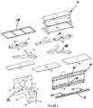
- FIG. 4is a collective figure showing the primary structural components of the console and mounts
- FIG. 5is a front perspective view of the television support with an frame configured for mounting a panel television with a non-standard hole pattern above a console;
- FIG. 6is a perspective view showing the mounting frame in position to be secured a wall
- FIG. 7is a rear perspective view of the offset arm with tilting and pivoting features in position for use on a mounting frame
- FIG. 8is a side elevational view of the pivot bearing and tilt mechanism
- FIG. 8Ais a top plan view of the pivot bearing and tilt mechanism
- FIG. 9is a detail view showing one of the panel brackets and the associated engagement hooks
- FIG. 10is a front perspective view of an alternative configuration for the mounting frame with panel brackets which accommodate a titling mechanism
- FIG. 10Ais a rear perspective of the configuration of FIG. 10 , showing an on-tilting pivot bearing
- FIG. 11is a side elevation view of the tilting mechanism for use with a mounting frame.
- FIG. 1there is illustrated a console base 10 carrying a plasma panel television 12 using a mounting frame 14 connection to the panel television through panel brackets 15 and 18 .
- the panel bracketsincorporated rail engagement hooks 110 .
- the hooks 110When supporting the panel 12 , the hooks 110 are received over rails 74 and 76 . Limited left and right movement of the panel television on the frame is possible until the hooks engage the stops 113 .
- the frameis carried by the offset arm 21 through the mounting structure which comprises a mounting plate 16 .
- the mounting plate 16is connected by pivot bearing 19 and the offset arm 21 to the long spine 22 .
- Spine 22in combination with leg structures 48 and 50 , support the television 12 and the shelf supports 24 , 26 and 28 (partially visible).
- the shelf supportsin turn carry the shelves 30 , 32 and 34 .
- the spine 22contains the wire and cable openings 36 , 38 , 40 and 42 .
- FIG. 2shows the same console base 10 , supporting a LCD television 44 that has four standard hard points with threaded bores 46 . These bores match up with a set of four holes on the plate 16 so that the panel television is supported directly from the plate 16 by inserting fasteners 47 into the bores.
- the VESA Standardcurrently calls for all LCD televisions to have at least four hard points and threaded holes positioned at the corners of a rectangular shape with distances between the holes being:
- the plate 16has holes to accommodate LCD televisions with all of those hole patterns.
- FIG. 3shows the details of the structure for the console 10 , which incorporates leg structures 48 and 50 .
- the upper members 52 of the leg structuressupport the upper shelf supports 24 and 26 .
- the lower members 58 of the leg structuressupport the console from the floor and support the lowermost shelf support 28 .
- the illustrated consoleis shown assembled with the short spine 62 which is bolted to the shelf supports 24 , 26 and 28 and so cooperates with the leg structures 48 and 50 to support weight carried on the upper shelves to the lower shelf support 28 and the floor on which the console rests.
- FIG. 4shows the primary structural components of an exemplary form of the kit including the short spine 62 and long spine 22 .
- the spines 22 , 62each have a series of spaced fastener openings 64 which permit the spines to be secured to the shelf supports and a series of spaced shelf slits 66 which accommodate that portion of the shelves that overlie the shelf supports.
- the leg structures 48 and 50are part of the kit as are the shelves 30 , 32 and 34 .
- a single shelf support 28is representative of the three shelf supports in the full kit.
- the offset mount 20is included.
- the illustrated offset mount 20is one without the tilt mechanism but includes the mounting plate 16 , the pivot bearing 19 and the offset arm 21 , with vertical flanges 70 and horizontal flanges 72 for connection to the long spine 22 .
- a panel bracket 15 with engagement hooks 110is representative of the two brackets that are part of the kit.
- the mounting frame 14is included for mounting larger televisions, televisions with non-standard hole patterns and for wall mounting.
- the kitmay alternatively or additionally include a tilting offset mount and a tilting mounting frame to be described later.
- FIG. 5is a front view of a console and long spine 22 .
- the installationis shown configured for use with a panel television to be carried on a mounting frame 14 .
- the panel brackets 15 and 18are shown in position over, and carried by, the rails 74 and 76 .
- the panel television, which would be attached to the brackets 15 and 18is not shown for clarity.
- FIG. 6shows the details of the mounting frame 14 .
- the rails 74 and 76are of square tubular stock and are interconnected by frame elements 78 , 80 and 82 also of tubular stock.
- the rails and frame elementsare desirably joined by welding to eliminate the need for the consumer to assemble them.
- a mounting frame produced using tubular stockis as stiff as a continuous formed plate of the same size, but much less expensive to produce.
- Open face channels 84 and 86bridge behind the rails and frame elements and have a series of openings of which holes 88 are representative. The open face of the channels is presented forwardly so that the consumer has access to insert and tighten lag bolts 77 that penetrate into the studs 87 A or other solid structure of the wall 87 .
- the holes 88are elongated so that the lag bolts can be precisely aligned with the studs. These same channels are used to secure the mounting frame 14 to the mounting plate 16 of the gooseneck mount 20 (see FIG. 1 ).
- a locking bar 89is shown partially inserted in holes 91 . The bar is fully inserted after a panel television and brackets is received over the rails 74 and 76 . The locking bar 89 prevents the panel television from being lifted or jarred off of the rails (see FIG. 7 ).
- FIG. 7is a detailed view of the offset mount with the details of the tilt mount illustrated.
- the offset arm 21is shown secured to the spine 22 by the flanges 70 and supports the pivot bearing 19 .
- the pivot bearing 19is made of a pivot pin 103 (not shown) fixedly attached to the holder 90 .
- the pivot pinis 103 received in a bearing receptacle 92 .
- Tilt brackets 94 and 96have overlapping flanges 102 and 104 and are hinged together at their upper ends by a horizontal hinge pin 98 received through the flanges 102 , 104 .
- the amount of pivotingis selected by rotating the hinge shaft 100 to frictionally hold the brackets in a fixed relative position as will appear in greater detail by an examination of FIG. 8 .
- FIG. 8shows the bracket flanges 102 and 104 which cooperate with slot 106 and hinge shaft 100 to limit the total range of tilting to a safe amount so that if the panel television moves the mount under the force of gravity and with insufficient friction developed by the shaft 100 , then the total titling movement will be limited to an amount such that the television won't contact the spine or the wall 87 .
- FIG. 8Ais a top view of the offset mount 20 and shows the pin 103 in the holder 90 .
- FIG. 9shows an exemplary panel bracket 15 .
- the panel bracket 15has a series of holes 111 which allow it to adapt to virtually any hole spacing on a panel television.
- the mountingis accomplished through a spacer 108 selected for proper length, such as spacer 108 to insure that the rear of the panel television (such as a television with a curved back) doesn't interfere with the rails and engagement hooks 110 , when the panel television is placed over the rails on the mounting frame.
- FIGS. 10 and 10Ashow an alternative embodiment for the mounting frame with a titling mechanism, which uses tilting panel brackets 128 for mounting to the rear of a panel television.
- a rail hook flange 134has hooks 135 received over the rails 74 and 76 .
- the hook flange 134has right angular related sides 136 with an arcuate slot 138 .
- a panel televisionis carried on brackets 132 .
- a handle 140is inserted through slot 138 in flange 136 and is threaded into the bracket 132 . When the handle 140 is tightened, the handle 140 bears up against the flange 136 and frictionally engages it so that the brackets 132 are held in a desired angular relationship to the frame.
- the tilt bracketsmay be used on a long spine 22 and offset arm 21 .
- the tilt bracketsalso function when the mounting frame is mounted on a wall 87 .
- FIG. 11shows the details of the tilting brackets of FIGS. 10 and 10A .
- the slot 138accommodates bolts 150 with carry a guide 151 .
- the bolts 150 and a third bolt 152are received in the bracket 128 . They act as stops for the tilting movement of a panel television carried on the brackets 132 so that the range of travel does not exceed a safe amount.
- the selected angleis locked in by operating of the handle 140 which frictionally engages the hook flange 136 and draws the bracket 132 into frictional engagement with the hook flange.
Landscapes
- Engineering & Computer Science (AREA)
- General Engineering & Computer Science (AREA)
- Mechanical Engineering (AREA)
- Physics & Mathematics (AREA)
- General Physics & Mathematics (AREA)
- Optics & Photonics (AREA)
- Devices For Indicating Variable Information By Combining Individual Elements (AREA)
Abstract
Description
Claims (11)
Priority Applications (1)
| Application Number | Priority Date | Filing Date | Title |
|---|---|---|---|
| US16/569,594US11311106B2 (en) | 2005-05-24 | 2019-09-12 | Television support and mounting kit |
Applications Claiming Priority (11)
| Application Number | Priority Date | Filing Date | Title |
|---|---|---|---|
| US11/135,888US7530538B2 (en) | 2005-05-24 | 2005-05-24 | Flat screen television support system |
| US89082807A | 2007-08-08 | 2007-08-08 | |
| US11/860,271US8079311B2 (en) | 2007-08-08 | 2007-09-24 | Television support and mounting kit |
| US12/417,902US9518695B2 (en) | 2005-05-24 | 2009-04-03 | Flat screen television support system |
| US13/316,792US8191485B1 (en) | 2007-08-08 | 2011-12-12 | Television support and mounting kit |
| US13/487,459US8622005B1 (en) | 2007-08-08 | 2012-06-04 | Television support and mounting kit |
| US14/109,253US9055814B2 (en) | 2005-05-24 | 2013-12-17 | Television support and mounting kit |
| US14/698,041US9215927B2 (en) | 2005-05-24 | 2015-04-28 | Television support and mounting kit |
| US14/929,541US9420886B2 (en) | 2005-05-24 | 2015-11-02 | Television support and mounting kit |
| US15/241,280US10413061B2 (en) | 2005-05-24 | 2016-08-19 | Television support and mounting kit |
| US16/569,594US11311106B2 (en) | 2005-05-24 | 2019-09-12 | Television support and mounting kit |
Related Parent Applications (1)
| Application Number | Title | Priority Date | Filing Date |
|---|---|---|---|
| US15/241,280ContinuationUS10413061B2 (en) | 2005-05-24 | 2016-08-19 | Television support and mounting kit |
Publications (2)
| Publication Number | Publication Date |
|---|---|
| US20200000225A1 US20200000225A1 (en) | 2020-01-02 |
| US11311106B2true US11311106B2 (en) | 2022-04-26 |
Family
ID=81213681
Family Applications (2)
| Application Number | Title | Priority Date | Filing Date |
|---|---|---|---|
| US16/569,594Expired - LifetimeUS11311106B2 (en) | 2005-05-24 | 2019-09-12 | Television support and mounting kit |
| US17/723,233Expired - LifetimeUS11819127B2 (en) | 2005-05-24 | 2022-04-18 | Television support and mounting kit |
Family Applications After (1)
| Application Number | Title | Priority Date | Filing Date |
|---|---|---|---|
| US17/723,233Expired - LifetimeUS11819127B2 (en) | 2005-05-24 | 2022-04-18 | Television support and mounting kit |
Country Status (1)
| Country | Link |
|---|---|
| US (2) | US11311106B2 (en) |
Cited By (6)
| Publication number | Priority date | Publication date | Assignee | Title |
|---|---|---|---|---|
| US20220136642A1 (en)* | 2020-10-30 | 2022-05-05 | Chengdu Boe Optoelectronics Technology Co., Ltd. | Display cable management structure and display |
| US20220244467A1 (en)* | 2005-05-24 | 2022-08-04 | Whalen Llc | Television support and mounting kit |
| US20230332733A1 (en)* | 2022-02-10 | 2023-10-19 | Steven Wai-Tong Cheng | Device compatible mounting stand |
| US20240019075A1 (en)* | 2022-07-13 | 2024-01-18 | Jorge Davidson | Floor Standing Panel Television Support Assembly |
| US11927299B1 (en)* | 2021-08-23 | 2024-03-12 | Randy Embrey | Two display monitor mechanism |
| WO2025054292A1 (en)* | 2023-09-08 | 2025-03-13 | The Rowing Company, Inc. | Tablet mounting system |
Families Citing this family (5)
| Publication number | Priority date | Publication date | Assignee | Title |
|---|---|---|---|---|
| CN111457215B (en)* | 2020-04-08 | 2021-08-06 | 江苏联怡通光电科技有限公司 | Plasma display screen |
| USD1037224S1 (en)* | 2022-04-12 | 2024-07-30 | Iworkhub Limited | Display mounting apparatus |
| USD1037223S1 (en)* | 2022-04-12 | 2024-07-30 | Iworkhub Limited | TV bracket |
| US20240197550A1 (en)* | 2022-12-16 | 2024-06-20 | Dawn Patrol Accessories LLC | Support and coupling interfaces for medical beds |
| CN219160026U (en) | 2023-02-03 | 2023-06-09 | 宁波索迈视听科技有限公司 | Audio-visual equipment support |
Citations (100)
| Publication number | Priority date | Publication date | Assignee | Title |
|---|---|---|---|---|
| US366525A (en) | 1887-07-12 | Fekro | ||
| US368388A (en) | 1887-08-16 | Adjustable book-holder | ||
| US866522A (en) | 1906-11-24 | 1907-09-17 | Thomas F Scanlon | Bed attachment. |
| US1324537A (en) | 1919-12-09 | Shelving construction | ||
| US1398601A (en) | 1920-05-28 | 1921-11-29 | Ivan L Osterhout | Adjustable reading-rack |
| US1590725A (en) | 1925-04-29 | 1926-06-29 | Homer Calvin Busby | Letter-box post |
| US1590726A (en) | 1921-07-18 | 1926-06-29 | Corsgren Bernhard | Adjustable supporting device |
| US1598569A (en) | 1925-09-23 | 1926-08-31 | Fitzhugh Champe Geraldine | Combined table and bookrest |
| US1692337A (en) | 1927-04-22 | 1928-11-20 | Forbes Dorothy | Adjustable holder |
| US1797847A (en) | 1928-02-24 | 1931-03-24 | James N Ward | Table attachment for beds |
| US2193647A (en) | 1937-04-05 | 1940-03-12 | Rush | Bed tray |
| US2359895A (en) | 1943-07-08 | 1944-10-10 | Courtland D Burton | Reading attachment for beds |
| US2535112A (en) | 1946-08-14 | 1950-12-26 | Ross B Woody | Adjustable bedside stand and tray |
| US2605155A (en) | 1949-05-18 | 1952-07-29 | William H Lewis | Tiltable and vertically adjustable bedside table |
| US3232249A (en) | 1964-03-04 | 1966-02-01 | Salvador N Perez | Swing table |
| US3358957A (en) | 1965-05-26 | 1967-12-19 | Wells Television Inc | Bedstead television support |
| US3875356A (en) | 1973-08-24 | 1975-04-01 | John V Heim | Call switch bracket for handicapped |
| US3905573A (en) | 1973-11-09 | 1975-09-16 | James M Davis | Adjustable reading aid |
| US4020510A (en) | 1974-05-28 | 1977-05-03 | Ralf Fabian | Hospital bed reading and writing device |
| US4076203A (en) | 1977-06-15 | 1978-02-28 | Mcdonnell Thomas M | Wall shelf arrangement |
| US4272136A (en) | 1979-05-29 | 1981-06-09 | Saturnino Sengua | Work station |
| US4410158A (en) | 1980-07-28 | 1983-10-18 | Maffei Eugene R | Over-bed television support frame |
| US4444323A (en) | 1981-05-11 | 1984-04-24 | Travis Handling Systems, Inc. | Retaining means for adjustable cantilever storage racks |
| US4993676A (en) | 1990-01-16 | 1991-02-19 | Fitts William E | Apparatus for supporting a television set from a ceiling |
| US5139223A (en) | 1991-04-09 | 1992-08-18 | Marty Sedighzadeh | Wall/ceiling support for television monitor |
| US5207405A (en) | 1991-07-29 | 1993-05-04 | Cobb Richard J | Television stand |
| US5282427A (en) | 1990-05-25 | 1994-02-01 | Helmut Steinhilber | Device for fastening a vertical support column to an article of furniture |
| US5549264A (en) | 1994-07-01 | 1996-08-27 | Baxter International Inc. | Support pole lift mechanism |
| US6158701A (en) | 1999-09-03 | 2000-12-12 | Deshler; Donald T. | Painting stand for vehicle parts |
| US6288891B1 (en) | 1996-11-21 | 2001-09-11 | Canon Kabushiki Kaisha | Movable display apparatus |
| US6327982B1 (en) | 1999-10-27 | 2001-12-11 | Stephen Jackson | Adjustable computer stand |
| US20020011544A1 (en) | 2000-03-30 | 2002-01-31 | Bosson Peter Thomas | Display device support system |
| US6347433B1 (en) | 1999-06-18 | 2002-02-19 | Cema Technologies, Inc. | Flat panel display tilt and swivel mechanism |
| USD454731S1 (en) | 2001-06-13 | 2002-03-26 | Sony Corporation | Stand for television receiver |
| USD458053S1 (en) | 2001-08-06 | 2002-06-04 | Elite Manufacturing Corporation | Entertainment center |
| US6425631B1 (en) | 2001-04-06 | 2002-07-30 | King Pao Enterprise Co., Ltd | Computer chair assembly |
| US6609691B2 (en) | 1999-06-07 | 2003-08-26 | Innovative Office Products, Inc. | Arm apparatus for mounting electronic devices with cable management system |
| USD480237S1 (en) | 2002-05-15 | 2003-10-07 | De Carolis Phil | Adjustable television support system |
| US6672465B2 (en) | 2001-12-04 | 2004-01-06 | Rite Hite Holding Corporation | Television stand |
| US20040011932A1 (en) | 2002-06-07 | 2004-01-22 | Simon Duff | Stand for flat panel display |
| US6695270B1 (en) | 2002-08-15 | 2004-02-24 | Ole Falk Smed | Flat panel display system |
| US6699146B1 (en) | 1997-02-12 | 2004-03-02 | Lifetime Products, Inc. | Parallelogrammic adjustment assembly for basketball goal systems |
| US20040041062A1 (en) | 2002-09-03 | 2004-03-04 | Ozolins Helmars E. | Support for one or more flat panel displays |
| US6704193B2 (en) | 2001-12-11 | 2004-03-09 | Koninklijke Philips Electronics N.V. | Space-saver design for personal computer keyboard |
| US20040079858A1 (en) | 2001-03-12 | 2004-04-29 | Alain Rudolf | Support device for liquid crystal flat screen |
| US20040079849A1 (en) | 2001-03-12 | 2004-04-29 | Alain Rudolf | Support device for a liquid crystal flat screen |
| US20040084578A1 (en) | 2002-11-05 | 2004-05-06 | Samsung Electronics, Co., Ltd. | Display apparatus |
| US20040084579A1 (en) | 2002-10-30 | 2004-05-06 | Samsung Electronics Co., Ltd. | Stand for display |
| US20040113031A1 (en) | 2002-11-05 | 2004-06-17 | Samsung Electronics Co., Ltd. | Monitor |
| US20040118984A1 (en) | 2002-09-27 | 2004-06-24 | Samsung Electronics Co., Ltd. | Display apparatus |
| USD495163S1 (en) | 2003-03-31 | 2004-08-31 | O'sullivan Industries, Inc. | Adjustable television stand |
| US6796536B1 (en) | 2002-09-04 | 2004-09-28 | Ebsoo Media, Inc. | Computer support apparatus and method |
| US20040188573A1 (en) | 2003-03-31 | 2004-09-30 | O'sullivan Industries, Inc. | Adjustable television stand |
| US20040188574A1 (en) | 2003-03-31 | 2004-09-30 | O'sullivan Industries, Inc. | Adjustable television stand |
| US20040211870A1 (en) | 2003-04-11 | 2004-10-28 | Jeff Bremmon | Universal mount bracket |
| US20040256524A1 (en) | 2003-03-19 | 2004-12-23 | Beck Robert L. | Computer workstation with moveable monitor support |
| US20050041379A1 (en) | 2003-08-21 | 2005-02-24 | Samsung Electronics Co., Ltd. | Monitor apparatus |
| US20050045782A1 (en) | 2003-08-28 | 2005-03-03 | Samsung Electronics Co., Ltd. | Display apparatus |
| US6905101B1 (en) | 2002-06-11 | 2005-06-14 | Chief Manufacturing Inc. | Adjustable, self-balancing flat panel display mounting system |
| US6923413B2 (en) | 2002-04-26 | 2005-08-02 | Premier Mounts | Mounting device for a flat screen display panel |
| USD507900S1 (en) | 2004-07-29 | 2005-08-02 | Z-Line Designs | Audio-video storage unit |
| US20050167549A1 (en) | 2004-01-30 | 2005-08-04 | Peter Ligertwood | Panel mounting unit |
| USD508801S1 (en) | 2004-08-27 | 2005-08-30 | Jahnke Gmbh & Co. Kg | Television stand |
| JP2006060754A (en) | 2004-08-18 | 2006-03-02 | Higa-Arts & Metal Inc | Wall unit for flat-screen TV |
| USD517349S1 (en) | 2005-01-21 | 2006-03-21 | Becker Designed, Inc. | Flat screen television stand |
| USD524080S1 (en) | 2005-01-31 | 2006-07-04 | Omnimount Systems, Inc. | Multi-level support system for media components |
| US7082882B2 (en) | 2003-08-12 | 2006-08-01 | Hill-Rom Services, Inc. | Frame mounted overbed table |
| US7118080B2 (en) | 2004-07-28 | 2006-10-10 | Chin-Chung Chan | Multi-functional adjustable computer support stand |
| USD531428S1 (en) | 2005-12-16 | 2006-11-07 | Choo Chong H | Entertainment center |
| US7175146B2 (en) | 2003-09-18 | 2007-02-13 | Samsung Electronics Co., Ltd. | Wall mount for display apparatus |
| US7178775B2 (en) | 2003-01-09 | 2007-02-20 | Csav, Inc. | Adjustable tilt mount |
| USD537658S1 (en) | 2006-05-11 | 2007-03-06 | Mart Tiller Corp. | Television stand |
| USD539125S1 (en) | 2005-08-03 | 2007-03-27 | Omnimount Systems, Inc. | Large universal adaptor for flat panel displays |
| USD539565S1 (en) | 2006-04-24 | 2007-04-03 | Z-Line Designs | Display stand |
| USD541138S1 (en) | 2005-04-18 | 2007-04-24 | Whalen Furniture Manufacturing Inc. | Television bracket |
| US7261261B2 (en) | 2003-05-23 | 2007-08-28 | Peter Ligertwood | Stand of free standing or mobile type |
| US20070246629A1 (en) | 2006-04-24 | 2007-10-25 | Z-Line Designs | Articulating swivel mounting mechanism |
| US20070252919A1 (en) | 2006-04-27 | 2007-11-01 | Mcgreevy Roy L | Remotely controlled adjustable flat panel display support system |
| USD564261S1 (en) | 2007-04-27 | 2008-03-18 | Bell'o International Corp. | Audio video shelving unit |
| USD565054S1 (en) | 2006-08-31 | 2008-03-25 | Omnimount Systems, Inc. | Compound tiltable mount for flat panel displays |
| USD566426S1 (en) | 2006-08-31 | 2008-04-15 | Omnimount Systems, Inc. | Stand with shelves and a tiltable mount for supporting a flat panel display |
| USD567546S1 (en) | 2007-08-15 | 2008-04-29 | Kuei-Chi Liu | Flat panel TV stand |
| USD570620S1 (en) | 2007-01-04 | 2008-06-10 | Atil Elektronik ses ve Goruntu Sistemleri ve Gida Urunleri Sanayi ve Ticaret Limited Sirketi | Television stand |
| US20080156949A1 (en) | 2006-12-28 | 2008-07-03 | Bell'o International L.L.C. | Flat panel display mounting system |
| US7404535B2 (en)* | 2005-03-18 | 2008-07-29 | Elexa Consumer Products, Inc. | Video monitor unit |
| USD574698S1 (en) | 2007-02-21 | 2008-08-12 | Csav, Inc. | Tilt bracket for display mount |
| US7445187B2 (en)* | 2005-03-08 | 2008-11-04 | Samsung Electronics Co., Ltd | Wall mount for display apparatus |
| US20090039212A1 (en) | 2007-08-08 | 2009-02-12 | Whalen Kenneth | Television Support and Mounting Kit |
| US7523907B2 (en)* | 2005-01-04 | 2009-04-28 | Benq Corporation | Hanger for electronic apparatus |
| US7530538B2 (en) | 2005-05-24 | 2009-05-12 | Whalen Furniture Manufacturing, Inc. | Flat screen television support system |
| USD595978S1 (en) | 2008-08-28 | 2009-07-14 | Bell'o International Corp. | Audio video shelving unit |
| USD604962S1 (en) | 2009-07-01 | 2009-12-01 | Blumenthal Distributing, Inc. | Television stand |
| WO2009143771A1 (en) | 2008-05-27 | 2009-12-03 | Sun Zhimin | Television shelf |
| USD607671S1 (en) | 2008-12-19 | 2010-01-12 | Z-Line Designs, Inc. | Flat screen TV console with bent kick back legs |
| US7690611B2 (en)* | 2004-10-19 | 2010-04-06 | Ergotron, Inc. | Display mounting system and method |
| US20110043978A1 (en) | 2008-01-04 | 2011-02-24 | Milestone Av Technologies Llc | Display mount with post-installation adjustment features |
| US20110079688A1 (en) | 2009-10-02 | 2011-04-07 | Grove James E | Folding TV stand assembly |
| US8813656B1 (en)* | 2012-08-08 | 2014-08-26 | LF Centennial Limted | Multi-configurable TV stand with top surface joined vertical structure |
| US8985534B1 (en)* | 2012-08-08 | 2015-03-24 | Lf Centennial Limited | Multi-configurable TV stand with bridging mount structure |
| US9279536B2 (en)* | 2003-05-30 | 2016-03-08 | Milestone Av Technologies Llc | Self-balancing adjustable flat panel mounting system |
Family Cites Families (1)
| Publication number | Priority date | Publication date | Assignee | Title |
|---|---|---|---|---|
| US11311106B2 (en)* | 2005-05-24 | 2022-04-26 | Whalen Llc | Television support and mounting kit |
- 2019
- 2019-09-12USUS16/569,594patent/US11311106B2/ennot_activeExpired - Lifetime
- 2022
- 2022-04-18USUS17/723,233patent/US11819127B2/ennot_activeExpired - Lifetime
Patent Citations (105)
| Publication number | Priority date | Publication date | Assignee | Title |
|---|---|---|---|---|
| US366525A (en) | 1887-07-12 | Fekro | ||
| US368388A (en) | 1887-08-16 | Adjustable book-holder | ||
| US1324537A (en) | 1919-12-09 | Shelving construction | ||
| US866522A (en) | 1906-11-24 | 1907-09-17 | Thomas F Scanlon | Bed attachment. |
| US1398601A (en) | 1920-05-28 | 1921-11-29 | Ivan L Osterhout | Adjustable reading-rack |
| US1590726A (en) | 1921-07-18 | 1926-06-29 | Corsgren Bernhard | Adjustable supporting device |
| US1590725A (en) | 1925-04-29 | 1926-06-29 | Homer Calvin Busby | Letter-box post |
| US1598569A (en) | 1925-09-23 | 1926-08-31 | Fitzhugh Champe Geraldine | Combined table and bookrest |
| US1692337A (en) | 1927-04-22 | 1928-11-20 | Forbes Dorothy | Adjustable holder |
| US1797847A (en) | 1928-02-24 | 1931-03-24 | James N Ward | Table attachment for beds |
| US2193647A (en) | 1937-04-05 | 1940-03-12 | Rush | Bed tray |
| US2359895A (en) | 1943-07-08 | 1944-10-10 | Courtland D Burton | Reading attachment for beds |
| US2535112A (en) | 1946-08-14 | 1950-12-26 | Ross B Woody | Adjustable bedside stand and tray |
| US2605155A (en) | 1949-05-18 | 1952-07-29 | William H Lewis | Tiltable and vertically adjustable bedside table |
| US3232249A (en) | 1964-03-04 | 1966-02-01 | Salvador N Perez | Swing table |
| US3358957A (en) | 1965-05-26 | 1967-12-19 | Wells Television Inc | Bedstead television support |
| US3875356A (en) | 1973-08-24 | 1975-04-01 | John V Heim | Call switch bracket for handicapped |
| US3905573A (en) | 1973-11-09 | 1975-09-16 | James M Davis | Adjustable reading aid |
| US4020510A (en) | 1974-05-28 | 1977-05-03 | Ralf Fabian | Hospital bed reading and writing device |
| US4076203A (en) | 1977-06-15 | 1978-02-28 | Mcdonnell Thomas M | Wall shelf arrangement |
| US4272136A (en) | 1979-05-29 | 1981-06-09 | Saturnino Sengua | Work station |
| US4410158A (en) | 1980-07-28 | 1983-10-18 | Maffei Eugene R | Over-bed television support frame |
| US4444323A (en) | 1981-05-11 | 1984-04-24 | Travis Handling Systems, Inc. | Retaining means for adjustable cantilever storage racks |
| US4993676A (en) | 1990-01-16 | 1991-02-19 | Fitts William E | Apparatus for supporting a television set from a ceiling |
| US5282427A (en) | 1990-05-25 | 1994-02-01 | Helmut Steinhilber | Device for fastening a vertical support column to an article of furniture |
| US5139223A (en) | 1991-04-09 | 1992-08-18 | Marty Sedighzadeh | Wall/ceiling support for television monitor |
| US5207405A (en) | 1991-07-29 | 1993-05-04 | Cobb Richard J | Television stand |
| US5549264A (en) | 1994-07-01 | 1996-08-27 | Baxter International Inc. | Support pole lift mechanism |
| US6288891B1 (en) | 1996-11-21 | 2001-09-11 | Canon Kabushiki Kaisha | Movable display apparatus |
| US6699146B1 (en) | 1997-02-12 | 2004-03-02 | Lifetime Products, Inc. | Parallelogrammic adjustment assembly for basketball goal systems |
| US6609691B2 (en) | 1999-06-07 | 2003-08-26 | Innovative Office Products, Inc. | Arm apparatus for mounting electronic devices with cable management system |
| US6347433B1 (en) | 1999-06-18 | 2002-02-19 | Cema Technologies, Inc. | Flat panel display tilt and swivel mechanism |
| US6158701A (en) | 1999-09-03 | 2000-12-12 | Deshler; Donald T. | Painting stand for vehicle parts |
| US6327982B1 (en) | 1999-10-27 | 2001-12-11 | Stephen Jackson | Adjustable computer stand |
| US20020011544A1 (en) | 2000-03-30 | 2002-01-31 | Bosson Peter Thomas | Display device support system |
| US20040079849A1 (en) | 2001-03-12 | 2004-04-29 | Alain Rudolf | Support device for a liquid crystal flat screen |
| US20040079858A1 (en) | 2001-03-12 | 2004-04-29 | Alain Rudolf | Support device for liquid crystal flat screen |
| US6425631B1 (en) | 2001-04-06 | 2002-07-30 | King Pao Enterprise Co., Ltd | Computer chair assembly |
| USD454731S1 (en) | 2001-06-13 | 2002-03-26 | Sony Corporation | Stand for television receiver |
| USD458053S1 (en) | 2001-08-06 | 2002-06-04 | Elite Manufacturing Corporation | Entertainment center |
| US6672465B2 (en) | 2001-12-04 | 2004-01-06 | Rite Hite Holding Corporation | Television stand |
| US6704193B2 (en) | 2001-12-11 | 2004-03-09 | Koninklijke Philips Electronics N.V. | Space-saver design for personal computer keyboard |
| US6923413B2 (en) | 2002-04-26 | 2005-08-02 | Premier Mounts | Mounting device for a flat screen display panel |
| USD480237S1 (en) | 2002-05-15 | 2003-10-07 | De Carolis Phil | Adjustable television support system |
| US20040011932A1 (en) | 2002-06-07 | 2004-01-22 | Simon Duff | Stand for flat panel display |
| US6905101B1 (en) | 2002-06-11 | 2005-06-14 | Chief Manufacturing Inc. | Adjustable, self-balancing flat panel display mounting system |
| US6758454B2 (en) | 2002-08-15 | 2004-07-06 | Ole Falk Smed | Flat panel display system |
| US6695270B1 (en) | 2002-08-15 | 2004-02-24 | Ole Falk Smed | Flat panel display system |
| US20040041062A1 (en) | 2002-09-03 | 2004-03-04 | Ozolins Helmars E. | Support for one or more flat panel displays |
| US6796536B1 (en) | 2002-09-04 | 2004-09-28 | Ebsoo Media, Inc. | Computer support apparatus and method |
| US20040118984A1 (en) | 2002-09-27 | 2004-06-24 | Samsung Electronics Co., Ltd. | Display apparatus |
| US20040084579A1 (en) | 2002-10-30 | 2004-05-06 | Samsung Electronics Co., Ltd. | Stand for display |
| US20040113031A1 (en) | 2002-11-05 | 2004-06-17 | Samsung Electronics Co., Ltd. | Monitor |
| US20040084578A1 (en) | 2002-11-05 | 2004-05-06 | Samsung Electronics, Co., Ltd. | Display apparatus |
| US7178775B2 (en) | 2003-01-09 | 2007-02-20 | Csav, Inc. | Adjustable tilt mount |
| US20040256524A1 (en) | 2003-03-19 | 2004-12-23 | Beck Robert L. | Computer workstation with moveable monitor support |
| USD495163S1 (en) | 2003-03-31 | 2004-08-31 | O'sullivan Industries, Inc. | Adjustable television stand |
| US20040188574A1 (en) | 2003-03-31 | 2004-09-30 | O'sullivan Industries, Inc. | Adjustable television stand |
| US7195213B2 (en) | 2003-03-31 | 2007-03-27 | O'sullivan Industries Inc. | Adjustable television stand |
| US20050236530A1 (en) | 2003-03-31 | 2005-10-27 | O'sullivan Industries, Inc. | Adjustable television stand |
| US20040188573A1 (en) | 2003-03-31 | 2004-09-30 | O'sullivan Industries, Inc. | Adjustable television stand |
| US20040211870A1 (en) | 2003-04-11 | 2004-10-28 | Jeff Bremmon | Universal mount bracket |
| US7261261B2 (en) | 2003-05-23 | 2007-08-28 | Peter Ligertwood | Stand of free standing or mobile type |
| US9279536B2 (en)* | 2003-05-30 | 2016-03-08 | Milestone Av Technologies Llc | Self-balancing adjustable flat panel mounting system |
| US7082882B2 (en) | 2003-08-12 | 2006-08-01 | Hill-Rom Services, Inc. | Frame mounted overbed table |
| US20050041379A1 (en) | 2003-08-21 | 2005-02-24 | Samsung Electronics Co., Ltd. | Monitor apparatus |
| US20050045782A1 (en) | 2003-08-28 | 2005-03-03 | Samsung Electronics Co., Ltd. | Display apparatus |
| US7175146B2 (en) | 2003-09-18 | 2007-02-13 | Samsung Electronics Co., Ltd. | Wall mount for display apparatus |
| US20050167549A1 (en) | 2004-01-30 | 2005-08-04 | Peter Ligertwood | Panel mounting unit |
| US7118080B2 (en) | 2004-07-28 | 2006-10-10 | Chin-Chung Chan | Multi-functional adjustable computer support stand |
| USD507900S1 (en) | 2004-07-29 | 2005-08-02 | Z-Line Designs | Audio-video storage unit |
| JP2006060754A (en) | 2004-08-18 | 2006-03-02 | Higa-Arts & Metal Inc | Wall unit for flat-screen TV |
| USD508801S1 (en) | 2004-08-27 | 2005-08-30 | Jahnke Gmbh & Co. Kg | Television stand |
| US7690611B2 (en)* | 2004-10-19 | 2010-04-06 | Ergotron, Inc. | Display mounting system and method |
| US7523907B2 (en)* | 2005-01-04 | 2009-04-28 | Benq Corporation | Hanger for electronic apparatus |
| USD517349S1 (en) | 2005-01-21 | 2006-03-21 | Becker Designed, Inc. | Flat screen television stand |
| USD524080S1 (en) | 2005-01-31 | 2006-07-04 | Omnimount Systems, Inc. | Multi-level support system for media components |
| US7445187B2 (en)* | 2005-03-08 | 2008-11-04 | Samsung Electronics Co., Ltd | Wall mount for display apparatus |
| US7404535B2 (en)* | 2005-03-18 | 2008-07-29 | Elexa Consumer Products, Inc. | Video monitor unit |
| USD541138S1 (en) | 2005-04-18 | 2007-04-24 | Whalen Furniture Manufacturing Inc. | Television bracket |
| US10413061B2 (en)* | 2005-05-24 | 2019-09-17 | Whalen Llc | Television support and mounting kit |
| US7530538B2 (en) | 2005-05-24 | 2009-05-12 | Whalen Furniture Manufacturing, Inc. | Flat screen television support system |
| USD539125S1 (en) | 2005-08-03 | 2007-03-27 | Omnimount Systems, Inc. | Large universal adaptor for flat panel displays |
| USD531428S1 (en) | 2005-12-16 | 2006-11-07 | Choo Chong H | Entertainment center |
| US20070246629A1 (en) | 2006-04-24 | 2007-10-25 | Z-Line Designs | Articulating swivel mounting mechanism |
| USD539565S1 (en) | 2006-04-24 | 2007-04-03 | Z-Line Designs | Display stand |
| US20070252919A1 (en) | 2006-04-27 | 2007-11-01 | Mcgreevy Roy L | Remotely controlled adjustable flat panel display support system |
| USD537658S1 (en) | 2006-05-11 | 2007-03-06 | Mart Tiller Corp. | Television stand |
| USD565054S1 (en) | 2006-08-31 | 2008-03-25 | Omnimount Systems, Inc. | Compound tiltable mount for flat panel displays |
| USD566426S1 (en) | 2006-08-31 | 2008-04-15 | Omnimount Systems, Inc. | Stand with shelves and a tiltable mount for supporting a flat panel display |
| US20080156949A1 (en) | 2006-12-28 | 2008-07-03 | Bell'o International L.L.C. | Flat panel display mounting system |
| USD570620S1 (en) | 2007-01-04 | 2008-06-10 | Atil Elektronik ses ve Goruntu Sistemleri ve Gida Urunleri Sanayi ve Ticaret Limited Sirketi | Television stand |
| USD574698S1 (en) | 2007-02-21 | 2008-08-12 | Csav, Inc. | Tilt bracket for display mount |
| USD564261S1 (en) | 2007-04-27 | 2008-03-18 | Bell'o International Corp. | Audio video shelving unit |
| US8079311B2 (en)* | 2007-08-08 | 2011-12-20 | Whalen Furniture Manufacturing, Inc. | Television support and mounting kit |
| US20090039212A1 (en) | 2007-08-08 | 2009-02-12 | Whalen Kenneth | Television Support and Mounting Kit |
| USD567546S1 (en) | 2007-08-15 | 2008-04-29 | Kuei-Chi Liu | Flat panel TV stand |
| US20110043978A1 (en) | 2008-01-04 | 2011-02-24 | Milestone Av Technologies Llc | Display mount with post-installation adjustment features |
| WO2009143771A1 (en) | 2008-05-27 | 2009-12-03 | Sun Zhimin | Television shelf |
| USD595978S1 (en) | 2008-08-28 | 2009-07-14 | Bell'o International Corp. | Audio video shelving unit |
| USD607671S1 (en) | 2008-12-19 | 2010-01-12 | Z-Line Designs, Inc. | Flat screen TV console with bent kick back legs |
| USD604962S1 (en) | 2009-07-01 | 2009-12-01 | Blumenthal Distributing, Inc. | Television stand |
| US20110079688A1 (en) | 2009-10-02 | 2011-04-07 | Grove James E | Folding TV stand assembly |
| US8813656B1 (en)* | 2012-08-08 | 2014-08-26 | LF Centennial Limted | Multi-configurable TV stand with top surface joined vertical structure |
| US8985534B1 (en)* | 2012-08-08 | 2015-03-24 | Lf Centennial Limited | Multi-configurable TV stand with bridging mount structure |
Non-Patent Citations (42)
| Title |
|---|
| Bell'O International Consolidated Final Invalidity Contentions 3:11-cv-02958. |
| CES Daily Newsletter, Jan. 5, 2006. |
| Commercial literature entitled "Bell'O simply . . . beautiful Home Theater Furniture, 2006 New Model Introductions". |
| Commercial Literature entitled "Brateck Bracket Technology," Lumi Legend Corporation, Brateck Enterprises, Ltd., 2006 Catalog. |
| Consolidated Claim Construction Order 3:11-cv-02958. |
| FAVS-02 Instruction Sheet (Published Jan. 5, 2006). |
| Furniture Today article entitled, "Special Report: New TV Formats", Apr. 28, 2003, pp. 1-2. |
| Installation instructions of Omnimount U3 Tilt Mount, Mar. 10, 2004, pp. 1-6. |
| Instruction manual entitled "Plasma Swinging Floater w/Mounting Bracket-Black PLSFLMB-B" Väs Furniture Mfg. Inc. |
| Instruction manual entitled, "Assembly Instructions for PP-59 Optional Flat Panel TV Mounting System," Bell'O International Corp. |
| Instruction manual entitled, "AVS-425 Assembly Instructions," Bell'O International Corp. |
| Instruction manual entitled, "Cappuccino 60" TV Stand HT7602, Golden Oak Furniture Mfg. |
| Instruction manual entitled, "Urban Wall TV Console and Plasma Floater," UL60ECPF Whalen Furniture Mfg. |
| Omnimount 54FB-F Assembly Instruction. |
| Omnimount 63FBHD-T Specification Sheet. |
| Omnimount G3FP Installation Instruction. |
| Omnimount TVM-27B 27 Single Pivot TV Wall Mount:, Pronto.com http://www.pronto.com/compare/omnimount-tvm27b-tvm27b-single-pivot 10305636039 (Accessed May 12, 2010). |
| Omnimount U1T: Universal Flat Panel Tilt Mount Installation Manual. |
| Omnimount U2T: Universal Flat Panel Tilt Mount Installation Manual. |
| Omnimount U3T: Universal Flat Panel Tilt Mount Installation Manual. |
| Omnimount UCL Installation Guide. |
| Price listing entitled, "Pro Bell'O Collection of Fine Home Theater Furniture 2006 New Model Introductions Confidential Price Schedule". |
| Ready Set Mount CC-K9 Instructions ("RSM"). |
| STC Space Saver TV and VCR/DVD Combo Mount up to 27-lnch Amazon.com http://www.amazon.com/Space-Saver_Combo_Mount-27 lnch/dp/B001B)B89Q/ref=pd_sbs_op_2 (Accessed May 12, 2011). |
| TechCraft PLM50 Kit and Assembly Instructions. |
| Techcraft, Inc. Consolidated Final Invalidity Contentions 3:11-cv-02958. |
| U.S. Appl. No. 95/002,619 Declaration of Marc Sculler with Exhibits. |
| U.S. Appl. No. 95/002,619 Declaration of Steve Sculler with Exhibits. |
| U.S. Appl. No. 95/002,619 Non-Final Office Action. |
| U.S. Appl. No. 95/002,619 Original Request for Reexamination. |
| U.S. Appl. No. 95/002,619 Patent Owner Response to Non-Final Office Action. |
| U.S. Appl. No. 95/002,619 Patent Owner Substitute Response (exceeded Page limit). |
| U.S. Appl. No. 95/002,619 Supplemental Declaration of Marc Sculler w/ Exhibits (filed with TPR Comments). |
| U.S. Appl. No. 95/002,619 Third Party Requester Comments to Patent Owner Response. |
| Walker Edison Consolidated Final Invalidity Contentions 3:11-cv-02958. |
| Whalen Cappuccino HT7102. |
| Whalen Furniture Manufacturing, Inc.ICWFPS Innovation Console with Flat Panel Solution Assembly Instructions ("ICWFPS"). |
| Whalen Furniture Manufacturing, Inc.'s AVC552-8VS Kit (Omega) and Assembly Instructions. |
| Whalen Furniture Manufacturing, Inc.'s XL-1 Kit and Assembly Instructions. |
| Z-Line Designs Consolidated Final Invalidity Contentions 3:11-cv-02958. |
| Z-Line Designs, Inc. Zen TV Stand Assembly Instructions. |
| Z-Line Zephyr TV Stand. |
Cited By (7)
| Publication number | Priority date | Publication date | Assignee | Title |
|---|---|---|---|---|
| US20220244467A1 (en)* | 2005-05-24 | 2022-08-04 | Whalen Llc | Television support and mounting kit |
| US11819127B2 (en)* | 2005-05-24 | 2023-11-21 | Whalen Llc | Television support and mounting kit |
| US20220136642A1 (en)* | 2020-10-30 | 2022-05-05 | Chengdu Boe Optoelectronics Technology Co., Ltd. | Display cable management structure and display |
| US11927299B1 (en)* | 2021-08-23 | 2024-03-12 | Randy Embrey | Two display monitor mechanism |
| US20230332733A1 (en)* | 2022-02-10 | 2023-10-19 | Steven Wai-Tong Cheng | Device compatible mounting stand |
| US20240019075A1 (en)* | 2022-07-13 | 2024-01-18 | Jorge Davidson | Floor Standing Panel Television Support Assembly |
| WO2025054292A1 (en)* | 2023-09-08 | 2025-03-13 | The Rowing Company, Inc. | Tablet mounting system |
Also Published As
| Publication number | Publication date |
|---|---|
| US20200000225A1 (en) | 2020-01-02 |
| US11819127B2 (en) | 2023-11-21 |
| US20220244467A1 (en) | 2022-08-04 |
Similar Documents
| Publication | Publication Date | Title |
|---|---|---|
| US10413061B2 (en) | Television support and mounting kit | |
| US11819127B2 (en) | Television support and mounting kit | |
| US8561551B2 (en) | Television support and mounting kit | |
| US9814312B2 (en) | Television mounting device | |
| US9408465B2 (en) | Method and device for wall mounting flat panel monitor and storing associated audio/video components | |
| US20110079685A1 (en) | Adjustable, Telescoping and Rotating Television Mount | |
| US7404609B2 (en) | Furniture system enclosing entertainment electronics in range of widths | |
| US7628367B2 (en) | Mount interface for suspended ceiling | |
| US20100006715A1 (en) | Floor standing support for an lcd or plasma display | |
| US20040118986A1 (en) | Slatwall mounting bracket | |
| US20110101179A1 (en) | Tv support structure with latching mechanism | |
| CA3154961A1 (en) | Articulating digital menu board and related methods | |
| US20100096515A1 (en) | Convertible Display Stand System and Method | |
| JPH11512639A (en) | Improved desk system | |
| CA2811974C (en) | Television support and mounting kit | |
| US20050230590A1 (en) | Flat panel display ceiling mount | |
| KR20070074474A (en) | Cabinet for display device | |
| CN221728717U (en) | A vertical wall cabinet | |
| EP0692207A1 (en) | Shelving assembly | |
| AU1258601A (en) | Support arm for visual display unit | |
| GB2464794A (en) | Clamping system for modular furniture |
Legal Events
| Date | Code | Title | Description |
|---|---|---|---|
| AS | Assignment | Owner name:WHALEN LLC, CALIFORNIA Free format text:ASSIGNMENT OF ASSIGNORS INTEREST;ASSIGNOR:LF CENTENNIAL LIMITED;REEL/FRAME:050371/0725 Effective date:20180828 Owner name:LF CENTENNIAL LIMITED, VIRGIN ISLANDS, BRITISH Free format text:ASSIGNMENT OF ASSIGNORS INTEREST;ASSIGNOR:WHALEN FURNITURE MANUFACTURING, INC.;REEL/FRAME:050371/0684 Effective date:20130531 Owner name:WHALEN FURNITURE MANUFACTURING, INC., CALIFORNIA Free format text:ASSIGNMENT OF ASSIGNORS INTEREST;ASSIGNORS:WHALEN, KENNETH;JONES, PAUL R.;REEL/FRAME:050363/0609 Effective date:20110328 | |
| FEPP | Fee payment procedure | Free format text:ENTITY STATUS SET TO UNDISCOUNTED (ORIGINAL EVENT CODE: BIG.); ENTITY STATUS OF PATENT OWNER: LARGE ENTITY | |
| STPP | Information on status: patent application and granting procedure in general | Free format text:DOCKETED NEW CASE - READY FOR EXAMINATION | |
| STPP | Information on status: patent application and granting procedure in general | Free format text:NON FINAL ACTION MAILED | |
| STPP | Information on status: patent application and granting procedure in general | Free format text:RESPONSE TO NON-FINAL OFFICE ACTION ENTERED AND FORWARDED TO EXAMINER | |
| STPP | Information on status: patent application and granting procedure in general | Free format text:FINAL REJECTION MAILED | |
| STPP | Information on status: patent application and granting procedure in general | Free format text:RESPONSE AFTER FINAL ACTION FORWARDED TO EXAMINER | |
| STPP | Information on status: patent application and granting procedure in general | Free format text:NOTICE OF ALLOWANCE MAILED -- APPLICATION RECEIVED IN OFFICE OF PUBLICATIONS | |
| STPP | Information on status: patent application and granting procedure in general | Free format text:PUBLICATIONS -- ISSUE FEE PAYMENT RECEIVED | |
| STPP | Information on status: patent application and granting procedure in general | Free format text:PUBLICATIONS -- ISSUE FEE PAYMENT VERIFIED | |
| STCF | Information on status: patent grant | Free format text:PATENTED CASE |