US11309714B2 - Micro-batteries for energy generation systems - Google Patents
Micro-batteries for energy generation systemsDownload PDFInfo
- Publication number
- US11309714B2 US11309714B2US15/341,984US201615341984AUS11309714B2US 11309714 B2US11309714 B2US 11309714B2US 201615341984 AUS201615341984 AUS 201615341984AUS 11309714 B2US11309714 B2US 11309714B2
- Authority
- US
- United States
- Prior art keywords
- power
- micro
- battery
- converter
- modules
- Prior art date
- Legal status (The legal status is an assumption and is not a legal conclusion. Google has not performed a legal analysis and makes no representation as to the accuracy of the status listed.)
- Active, expires
Links
Images


Classifications
- H02J3/385—
- H—ELECTRICITY
- H02—GENERATION; CONVERSION OR DISTRIBUTION OF ELECTRIC POWER
- H02J—CIRCUIT ARRANGEMENTS OR SYSTEMS FOR SUPPLYING OR DISTRIBUTING ELECTRIC POWER; SYSTEMS FOR STORING ELECTRIC ENERGY
- H02J3/00—Circuit arrangements for AC mains or AC distribution networks
- H02J3/38—Arrangements for parallely feeding a single network by two or more generators, converters or transformers
- H02J3/381—Dispersed generators
- H—ELECTRICITY
- H02—GENERATION; CONVERSION OR DISTRIBUTION OF ELECTRIC POWER
- H02J—CIRCUIT ARRANGEMENTS OR SYSTEMS FOR SUPPLYING OR DISTRIBUTING ELECTRIC POWER; SYSTEMS FOR STORING ELECTRIC ENERGY
- H02J3/00—Circuit arrangements for AC mains or AC distribution networks
- H02J3/38—Arrangements for parallely feeding a single network by two or more generators, converters or transformers
- H02J3/388—Islanding, i.e. disconnection of local power supply from the network
- H—ELECTRICITY
- H02—GENERATION; CONVERSION OR DISTRIBUTION OF ELECTRIC POWER
- H02J—CIRCUIT ARRANGEMENTS OR SYSTEMS FOR SUPPLYING OR DISTRIBUTING ELECTRIC POWER; SYSTEMS FOR STORING ELECTRIC ENERGY
- H02J7/00—Circuit arrangements for charging or depolarising batteries or for supplying loads from batteries
- H02J7/34—Parallel operation in networks using both storage and other DC sources, e.g. providing buffering
- H02J7/35—Parallel operation in networks using both storage and other DC sources, e.g. providing buffering with light sensitive cells
- H—ELECTRICITY
- H02—GENERATION; CONVERSION OR DISTRIBUTION OF ELECTRIC POWER
- H02J—CIRCUIT ARRANGEMENTS OR SYSTEMS FOR SUPPLYING OR DISTRIBUTING ELECTRIC POWER; SYSTEMS FOR STORING ELECTRIC ENERGY
- H02J2207/00—Indexing scheme relating to details of circuit arrangements for charging or depolarising batteries or for supplying loads from batteries
- H02J2207/20—Charging or discharging characterised by the power electronics converter
- H—ELECTRICITY
- H02—GENERATION; CONVERSION OR DISTRIBUTION OF ELECTRIC POWER
- H02J—CIRCUIT ARRANGEMENTS OR SYSTEMS FOR SUPPLYING OR DISTRIBUTING ELECTRIC POWER; SYSTEMS FOR STORING ELECTRIC ENERGY
- H02J2300/00—Systems for supplying or distributing electric power characterised by decentralized, dispersed, or local generation
- H02J2300/20—The dispersed energy generation being of renewable origin
- H02J2300/22—The renewable source being solar energy
- H02J2300/24—The renewable source being solar energy of photovoltaic origin
- H02J2300/26—The renewable source being solar energy of photovoltaic origin involving maximum power point tracking control for photovoltaic sources
- H—ELECTRICITY
- H02—GENERATION; CONVERSION OR DISTRIBUTION OF ELECTRIC POWER
- H02J—CIRCUIT ARRANGEMENTS OR SYSTEMS FOR SUPPLYING OR DISTRIBUTING ELECTRIC POWER; SYSTEMS FOR STORING ELECTRIC ENERGY
- H02J3/00—Circuit arrangements for AC mains or AC distribution networks
- H02J3/38—Arrangements for parallely feeding a single network by two or more generators, converters or transformers
- H02J3/46—Controlling of the sharing of output between the generators, converters, or transformers
- Y—GENERAL TAGGING OF NEW TECHNOLOGICAL DEVELOPMENTS; GENERAL TAGGING OF CROSS-SECTIONAL TECHNOLOGIES SPANNING OVER SEVERAL SECTIONS OF THE IPC; TECHNICAL SUBJECTS COVERED BY FORMER USPC CROSS-REFERENCE ART COLLECTIONS [XRACs] AND DIGESTS
- Y02—TECHNOLOGIES OR APPLICATIONS FOR MITIGATION OR ADAPTATION AGAINST CLIMATE CHANGE
- Y02E—REDUCTION OF GREENHOUSE GAS [GHG] EMISSIONS, RELATED TO ENERGY GENERATION, TRANSMISSION OR DISTRIBUTION
- Y02E10/00—Energy generation through renewable energy sources
- Y02E10/50—Photovoltaic [PV] energy
- Y02E10/56—Power conversion systems, e.g. maximum power point trackers
- Y—GENERAL TAGGING OF NEW TECHNOLOGICAL DEVELOPMENTS; GENERAL TAGGING OF CROSS-SECTIONAL TECHNOLOGIES SPANNING OVER SEVERAL SECTIONS OF THE IPC; TECHNICAL SUBJECTS COVERED BY FORMER USPC CROSS-REFERENCE ART COLLECTIONS [XRACs] AND DIGESTS
- Y02—TECHNOLOGIES OR APPLICATIONS FOR MITIGATION OR ADAPTATION AGAINST CLIMATE CHANGE
- Y02E—REDUCTION OF GREENHOUSE GAS [GHG] EMISSIONS, RELATED TO ENERGY GENERATION, TRANSMISSION OR DISTRIBUTION
- Y02E70/00—Other energy conversion or management systems reducing GHG emissions
- Y02E70/30—Systems combining energy storage with energy generation of non-fossil origin
Definitions
- a conventional solar energy generation systemincludes an array of PV modules connected together on one or more strings and a combination of individual component systems, such as a combiner for combining direct current (DC) outputs of the one or more strings to one or more string inverters for converting the combined DC output from the strings to alternating current (AC), and a physical interface to AC utility grid for exporting power/energy or use locally—typically on the load side of the utility meter, between the meter and the customer's main electrical panel.
- DCdirect current
- ACalternating current
- the solar energy generation systemprovides excess AC power generated back to the AC grid, resulting in cost benefits to the customer and/or owner of the system.
- Such energy generation systemscan provide generated power/energy back to the utility grid, but are unable to store generated energy for use when the grid is unavailable, such as during an outage, or export to grid in the night time when solar is not available.
- on-site energy storagehas been developed to store excess energy for use during grid outage or export energy in the nighttime.
- On-site energy storagealso allows the customer to store energy generated during the day and then consume that power after the sun has set, reducing the customer's peak demand.
- on-site energy storagehelps utilities stabilize the grid by supplying energy to enhance demand response, shave demand peaks, shift loads to lower demand and economic energy dispatch between peak and off-peak hours. Utilizing on-site energy storage, however, has decreased the efficiency of these energy generation systems. Thus, improvements to such energy generation systems are desired.
- Embodimentsdescribe PV systems configured with micro-batteries, where each micro-battery is devoted to a particular PV module for storing energy at low voltage and converting DC power to AC power. Such PV systems may be referred to herein as “micro-battery PV systems”. Micro-battery PV systems, when compared to conventional energy generation systems, are more efficient and less visibly intrusive in design.
- an energy generation systemincludes: a photovoltaic (PV) array including a plurality of PV modules for generating direct current (DC) power; a plurality of power converter pairs coupled to the plurality of PV modules and configured to convert the generated DC power to alternating current (AC) power, each power converter pair of the plurality of power converter pairs includes a DC-to-DC converter coupled to a DC-to-AC inverter, where the DC-to-DC converter is directly coupled to a respective PV module; and a plurality of battery packs coupled to the plurality of power converter pairs, each battery pack is directly coupled to a respective DC-to-DC converter and configured to store DC power from the respective PV module and output stored DC power to the respective power converter pair.
- PVphotovoltaic
- the DC-to-DC converter of each power converter paircan be configured to buck and boost the generated DC power from the respective PV module.
- Each power converter paircan be further configured to perform maximum power-point tracking (MPPT) on generated DC power from its respective PV module.
- MPPTmaximum power-point tracking
- Each battery packcan be coupled to its respective power converter pair through a power cable that is plugged into a socket of a housing for the respective power converter pair.
- the plurality of power converter pairs and the plurality of battery packscan form a plurality of micro-batteries, each micro-battery including a power converter pair and a respective battery pack.
- the plurality of micro-batteriescan be serially connected.
- the plurality of PV modules and the plurality of micro-batteriescan be equal in number. Each micro-battery can be coupled to a different PV module.
- the plurality of micro-batteriescan be coupled to less than all PV modules of the plurality of PV modules. Some micro-batteries can be coupled to more than one PV module of the plurality of PV modules.
- Each battery packcan include battery cells and a battery management system (BMS).
- BMSbattery management system
- Each battery packcan further include a battery pack DC-to-DC converter configured to buck and boost DC power from the DC-to-DC converter of the respective power converter pair.
- an energy generation systemincludes: a photovoltaic (PV) array including a plurality of PV modules for generating direct current (DC) power; and a plurality of micro-batteries coupled to the plurality of PV modules, each micro-battery including: a DC-to-DC converter directly coupled to a respective PV module and configured to receive generated DC power from the respective PV module and convert the generated DC power to a converted DC power having a different voltage level than the generated DC power; a DC-to-AC inverter coupled to the DC-to-DC converter and configured to receive the converted DC power and convert the converted DC power to alternating current (AC) power; and a battery pack coupled to the DC-to-DC converter, the battery pack configured to store DC power from the respective PV module and output stored DC power to the DC-to-DC converter.
- PVphotovoltaic
- DCdirect current
- the DC-to-DC buck-boost converter, the DC-to-AC inverter, and the battery packcan be housed within the same enclosure.
- the DC-to-DC converter of each invertercan be configured to buck and boost the generated DC power from the respective PV module.
- the plurality of micro-batteriescan be coupled to less than all PV modules of the plurality of PV modules.
- the battery packcan include battery cells and a battery management system (BMS).
- BMSbattery management system
- the battery packcan further include a battery pack DC-to-DC converter configured to buck and boost DC power from the DC-to-DC converter.
- an energy generation deviceincludes: a direct current (DC)-to-DC converter directly coupled to a photovoltaic (PV) module and configured to buck and boost a DC input power from the PV module to a converted DC power; a DC-to-alternating current (AC) converter coupled to the DC-to-DC converter and configured to convert the converted DC power to AC power; and a battery pack directly coupled to the DC-to-DC converter, the battery pack configured to store DC power generated by the PV module and discharge the stored DC power to the DC-to-DC converter.
- DCdirect current
- PVphotovoltaic
- the battery packcan include battery cells and a battery management system (BMS).
- BMSbattery management system
- FIG. 1is a block diagram of a micro-inverter PV system.
- FIG. 2is a block diagram of a micro-inverter PV system with on-site energy storage.
- FIG. 3is a block diagram of an exemplary micro-battery PV system where respective power converters and energy storage devices of each micro-battery are housed in the same enclosure, according to some embodiments of the present disclosure.
- FIG. 4is a block diagram of an exemplary micro-battery PV system where respective power converters and energy storage devices of each micro-battery are housed in separate enclosures, according to some embodiments of the present disclosure.
- FIG. 5is a block diagram of an exemplary micro-battery PV system where some micro-batteries are coupled to more than one PV module, according to some embodiments of the present disclosure.
- FIG. 6is a block diagram of an exemplary micro-battery including power converters and a battery pack that are housed in the same enclosure, according to some embodiments of the present disclosure.
- FIG. 7is a block diagram of an exemplary micro-battery including power converters and a battery pack that are housed in separate enclosures, according to some embodiments of the present disclosure.
- FIG. 8is a block diagram illustrating an exemplary micro-battery configured with a revenue-grade meter system, according to some embodiments of the present disclosure.
- FIG. 9is a block diagram of an exemplary micro-battery PV system configured for a AC multi-phase configuration, according to some embodiments of the present disclosure.
- FIG. 10is a block diagram of an exemplary micro-battery PV system configured for a split single-phase configuration, according to some embodiments of the present disclosure.
- FIG. 11is a block diagram of a serial interconnection between micro-battery packs for a micro-battery PV system, according to some embodiments of the present disclosure.
- FIG. 12is a block diagram of a parallel interconnection between micro-battery packs for a micro-battery PV system, according to some embodiments of the present disclosure.
- Solar energy generation systemscouple micro-batteries to respective PV modules in a solar energy generation system, thereby forming a micro-battery PV system.
- Each micro-batterycan include a power converter coupled with an energy storage device, such as a battery pack.
- the battery packenables DC power generated from a PV module to be stored before or in addition to being converted to AC power to output to a load(s) or the utility grid.
- Storing DC power prior to conversion to AC powerreduces the number of power conversions needed to implement on-site energy storage for an energy generation system, thereby reducing power conversion losses and enhancing the overall efficiency of the energy generation system. This is unlike conventional micro-inverter energy generation systems with centralized power storage that have several more energy conversions which decreases the efficiency at which the energy generation system can provide stored power to a load or the utility grid, as will be discussed further herein.
- a micro-inverter PV systemuses several smaller-sized inverters (matched to each PV module power rating) instead of one large string inverter (rated to match all combined PV strings) for converting DC power generated by a plurality of PV modules.
- Each micro-invertermay be dedicated to convert DC power from a respective PV module to AC power.
- a single micro-inverterwill service between one and four PV modules.
- FIG. 1illustrates exemplary conventional micro-inverter PV system 100 .
- Micro-inverter PV system 100can include a plurality of PV modules 102 a - f for generating DC power, and a plurality of micro-inverters 104 a - f for receiving the generated DC power from PV modules 102 a - f and converting the generated DC power to AC power for outputting to AC grid 110 .
- Each micro-inverter 102 a - fcan be coupled to a respective PV module 102 a - f and be dedicated to converting DC power from that respective PV module.
- micro-inverter 104 amay be coupled to PV module 102 a and dedicated to converting DC power from PV module 102 a to AC power.
- Micro-inverters 104 b - f and PV modules 102 b - fcan perform maximum power-point tracking (MPPT) on power provided by PV modules 102 a - f.
- MPPTmaximum power-point tracking
- Each micro-inverter 104 a - fmay be a specific type of micro-inverter, such as a parallel micro-inverter, serial micro-inverter, and an advanced micro-inverter.
- a parallel micro-inverteris coupled to other parallel micro-inverters in a parallel configuration for outputting AC power to AC grid 110 .
- Each micro-inverterincludes a DC-to-DC boost converter and a DC-to-AC inverter.
- the DC-to-DC boost convertermay boost input voltage (20-100V) from the respective PV module to a high DC voltage (170-400V) and perform DC-to-AC conversion to output AC power to AC grid 110 .
- AC powercan be outputted to an intermediate AC bus that runs from the array to an on-site interface to the AC grid, such as a customer's main electrical panel. This is because the output voltage of PV modules 102 a - f may not be at a voltage level high enough to be over the voltage level of AC grid 110 .
- the boost convertercan boost the input voltage to a level higher than the operating voltage of AC grid 110 to compensate for the expected power loss from converting DC power to AC power, such as a boost to 170V DC power for a 120V AC grid, 330V DC power for a 208Vac grid, 370V DC power for a 240V AC grid, and the like).
- a serial micro-inverteris coupled to other serial micro-inverters in a serial configuration for outputting AC power to AC grid 110 .
- Each serial micro-inverterincludes a DC-to-AC inverter for converting DC power to AC power.
- a DC-to-DC converteris not needed because AC power outputted by each serial micro-inverter can aggregate to output a combined power that is higher than each outputted power separately.
- the combined power outputmay have a voltage that is high enough to be compatible with AC grid 110 .
- each micro-inverter 104 a - fmay be an advanced micro-inverter.
- An advanced micro-inverteris coupled to other advanced micro-inverters in a serial configuration for outputting AC power to AC grid 110 .
- Each advanced micro-inverterreceives generated DC voltage (20-100V) and adds the voltage as a time sequence step of an output AC waveform.
- the number of advanced micro-inverterscan be chosen to match the voltage level of the AC grid.
- Micro-inverter PV system 100is suitable for outputting excess generated power back to AC grid 110 , which may be advantageous for customers in jurisdictions that allow for net energy metering. PV system 100 , however, cannot store the excess generated power for use when PV modules 102 a - f are not generating power, such as at night or during a storm or blackout. Accordingly, micro-inverter PV systems with on-site energy storage have been developed to store excess energy for reasons discussed herein.
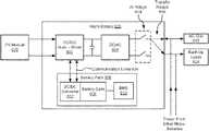
- FIG. 2illustrates exemplary micro-inverter PV system 200 with on-site energy storage. Having on-site energy storage enables PV system 200 to provide power to loads, e.g., back-up loads 224 , at an installation site when AC grid 110 is unavailable, such as during an outage, or enable PV system 200 to export/import energy to/from AC grid 110 when AC grid 110 is available.
- PV system 200includes PV modules 102 a - f and micro-inverters 104 a - f for receiving generated DC power from PV modules 102 a - f and converting the generated DC power to AC power for outputting to AC grid 110 .
- PV system 200also includes storage inverter 212 and battery pack 218 for providing on-site energy storage.
- AC powercan be provided by micro-inverters 104 a - f and/or AC grid 110 to storage inverter 212 , which can then convert the AC power to DC power and output the converted DC power to charge battery pack 218 .
- Storage inverter 212can include bi-directional DC-to-AC inverter 214 for converting the received AC power to DC power, and DC-to-DC converter 216 for boosting and/or bucking the converted DC power to a higher/lower DC power during charging and vice-versa for discharging.
- Battery pack 218can include battery cells 220 and battery management system (BMS) 224 .
- Battery cells 220may be an electro-chemical devices that are capable of storing charge, and BMS 224 may manage the operation of battery cells 220 .
- Battery pack 218can include a bi-directional DC-to-DC buck and/or boost converter 222 to manage the voltage level of power flowing into and out of battery cells 220 .
- DC-to-DC buck/boost converter 222 and DC-to-DC converter 216can be mutually exclusive in that there only need to be one DC-to-DC buck/boost converter for managing the voltage level of power provided to and from battery pack 218 . Accordingly, in various embodiments, either DC-to-DC buck/boost converter 216 is present, DC-to-DC buck/boost converter 222 is present, or none of them are present, as indicated by dotted lines shown in FIG. 2 .
- Power stored in battery pack 218can be provided to back-up loads 224 during AC grid 110 outage.
- DC power stored in battery cells 220is outputted to storage inverter 212 , which converts the DC power to AC power and then outputs the converted AC power to back-up loads 224 or AC grid 110 .
- Transfer relays 226 and anti-islanding relays 228can be positioned at the output of DC-to-AC inverter 214 to manage power flow into and out of storage inverter 212 .
- Transfer relays 226can be electrical or mechanical relays capable of coupling an input between two outputs.
- transfer relays 226can be mechanical relays configured to couple storage inverter 212 to AC grid 110 or back-up loads 224 .
- Anti-islanding relays 228can be switches configured to open and close an electrical path to allow or prevent power flow into and out of storage inverter 212 .
- transfer relays 226can be positioned outside the storage inverter but still be controlled by it.
- power provided by PV modules 102 a - f by way of micro-inverters 104 a - fmust undergo several power conversions in order to provide on-site energy storage for PV system 200 .
- the AC powerfurther undergoes two additional power conversions, one additional power conversion to convert AC power to DC power for storing DC power in battery pack 218 , and another additional power conversion to convert the stored DC power to AC power to output to back-up loads 224 .
- Each power conversionresults in power loss, which causes inefficient utilization of generated power from PV modules 102 a - f .
- storage inverter 212 and battery pack 218are positioned at the ground level instead of on the roof, the presence of storage inverter 212 and battery pack 218 is visible and thus can negatively impact the aesthetics of the installation site, especially when it is a residential building such as a customer's home.
- a micro-battery PV systemis more efficient than micro-inverter PV systems 100 and 200 discussed herein with respect to FIGS. 1 and 2 because it has less power conversions and is more optimized. Instead of requiring a separate storage inverter and a large battery pack, micro-battery PV systems do not need a separate storage inverter and splits the large battery pack into several smaller battery packs, each configured to store energy provided by one or more respective PV modules.
- Micro-battery PV systemsinclude a plurality of micro-batteries where each micro-battery may be formed of at least one power converter and an energy storage device that can be housed in the same enclosure, or housed in separate enclosures, as will be discussed further herein.
- the power convertercould be just DC/AC converter or DC/DC and DC/AC converter as appropriate to match the PV module and battery pack voltage. For example: if a PV module has Vmp (max power voltage) of 45V and when the battery voltage is 45V, then there is no need for additional DC-DC power converter to charge/discharge the battery from PV but a DC-DC power converter may be required to boost the PV and/or battery voltage to higher voltage for DC-AC conversion. So, the number of DC-DC converters inside the micro-battery depends on the voltages of PV module and the battery pack.
- FIG. 3illustrates exemplary micro-battery PV system 300 , according to some embodiments of the present disclosure.
- Micro-battery PV system 300can include PV modules 302 a - f arranged in two strings of three PV modules each.
- FIG. 3illustrates only six PV modules arranged in two strings, embodiments are not limited to such configurations and that other micro-battery PV systems can have more or less PV modules arranged in more or less strings where each string includes more or less PV modules.
- Each PV module 302 a - fcan be coupled to a respective micro-battery 304 a - f , which can include at least one power converter 306 a - f for converting DC power provided by respective PV modules 302 a - f to AC power and outputting the converted AC power to AC grid 310 and/or back-up loads 312 , as will be discussed in further detail herein.
- the number of micro-batteries 304 a - fis equal to the number of PV modules 302 a - f such that each micro-battery is coupled to a different PV module.
- each micro-battery 304 a - falso includes an energy storage device, such as a respective one of battery packs 308 a - f .
- Each battery pack 308 a - fcan store DC power provided by a respective PV module 302 a - f prior to conversion to AC power.
- each battery pack 308 a - fcan output its stored DC power to be converted to AC power by a respective power converter 306 a - f and subsequently be provided to AC grid 310 and/or back-up loads 312 .
- battery packs 308 a - fare positioned to receive DC power from respective PV modules prior to conversion to AC power by power converters 306 a - f .
- Being able to store the DC power prior to conversion to AC powereliminates two power conversions required in other PV systems without micro-batteries, such as PV system 200 in FIG. 2 (e.g., the conversion from DC power to AC power to output AC power to back-up loads 224 , and the conversion from AC power to DC power to store energy in battery pack 218 ). Elimination of these two power conversions significantly increases the efficiency of the energy generation system because it avoids the power losses associated with the two additional power conversions.
- each micro-battery 304 a - fis positioned proximate to a respective PV module 302 a - f .
- each micro-battery 304 a - fcan be mounted directly underneath the respective PV module 302 a - f . This will greatly simplify the process of system installation since all connections for PV module output, storage and AC output are incorporated in a single functional unit at the PV module.
- the AC output to the AC grid and back-up loadscould be two separate AC buses, provided there are internal transfer relays inside the micro-battery. In other embodiments, if the relay(s) is positioned external to the micro-battery or to the entire group of micro-batteries of the string/array, then the same AC output could output AC current into AC grid or provide AC voltage to back-up loads.
- each power converter 306 a - f and battery pack 308 a - fcan be housed within the same enclosure, as shown in FIG. 3 .
- solid rectangle lines surrounding respective power converters 306 a - f and battery packs 308 a - findicate that both respective power converters 306 a - f and battery packs 308 a - f are housed within the same enclosure.
- each power converter 306 a - f and battery pack 308 a - fcan be housed within separate enclosures as shown in FIG. 4 .
- FIG. 4illustrates exemplary micro-battery PV system 400 having micro-batteries 404 formed of power converters 406 a - f and battery packs 408 a - f that are housed in separate enclosures, according to some embodiments of the present disclosure.
- the dotted rectangles surrounding respective power converters 406 a - f and battery packs 408 a - fand the separate solid rectangles surrounding each individual inverter and battery pack, indicate that both respective power converters 406 a - f and battery packs 408 a - f are housed within separate enclosures.
- power converters 406 a - fcan be substantially similar to conventional micro-inverters in that each power converter 406 a - f can be dedicated to converting DC power to AC power for respective PV modules, but is different in that each power converter 406 a - f has a separate input plug for coupling with a respective battery pack 408 a - f .
- the battery packs 408 a - fcan be plugged into sockets of housings for respective power converters 406 a - f via an electrical cable.
- the housing of each power converter 406 a - fcan be configured to include an input socket to receive the electrical cable from a respective battery pack.
- the operating voltage (Vmp) of the PV moduleis different from battery pack voltage
- FIGS. 3 and 4illustrate micro-battery PV systems 300 and 400 as having a designated micro-battery for each respective PV module, embodiments are not limited to such configurations.
- a micro-batterymay be coupled to more than one PV module at the intersection of power lines from the PV modules.
- FIG. 5illustrates exemplary micro-battery PV system 500 where some micro-batteries are coupled to two PV modules. Although only showing a micro-battery coupled to two PV modules, it is to be appreciated that this architecture can expand to include more PV modules per micro-battery (e.g., three, four, or more PV modules per micro-battery).
- micro-battery PV system 500may include micro-batteries 504 a - d , where some micro-batteries are coupled to more than one PV module in a PV string. However, each micro-battery is coupled to less than all of the PV modules. For instance, a string containing PV modules 502 a - c can have micro-batteries 504 a and 504 b where micro-battery 504 a is coupled to PV module 502 a , and micro-battery 504 b is coupled to PV modules 502 b and 502 c .
- micro-battery 504 cis coupled to PV module 502 d
- micro-battery 504 dis coupled to PV modules 502 e and 502 f
- one or more micro-batteriescan be configured to support more than one PV module.
- micro-batteriescan store DC power as well as convert stored DC power to AC power for outputting to the AC grid or back-up loads.
- Implementing energy storage utilization at the PV module level and in several smaller energy capacities/operating voltage levelscan significantly improve the efficiency of the overall energy generation system by reducing the number of power conversions required to implement on-site energy storage for a PV system.
- each micro-batterycan include at least one inverter and a battery pack that are housed in the same or separate enclosures.
- FIG. 6is a block diagram illustrating the structure of exemplary micro-battery 600 including a power converter pair and a battery pack that are housed in the same enclosure, according to some embodiments of the present disclosure.
- the power converter paircan include DC-to-DC buck-boost converter 602 for receiving DC power from a respective PV module 620 , which can be similar to any of PV modules 302 a - f in FIG. 3 , and a DC-to-AC inverter 604 for receiving converter power from DC-to-DC buck-boost converter 602 .
- DC-to-DC buck-boost converter 602is directly coupled to PV module 620 for receiving generated DC power.
- DC-to-DC buck-boost converter 602can boost the received DC power to a higher voltage level.
- DC-to-DC buck-boost converter 602may convert the received DC voltage to a higher voltage level for outputting to DC-to-AC inverter 604 .
- the higher voltage levelcan match the operating voltage level of AC grid 622 (i.e., AC grid 310 in FIG. 3 ) and/or operation of one or more back-up loads 624 (i.e., back-up loads 312 in FIG. 3 ).
- DC-to-AC inverter 604can receive the boosted DC voltage and invert the boosted DC voltage to AC for outputting to AC grid 622 and/or back-up loads 624 .
- this micro-invertercan be called a “hybrid micro-inverter” if the battery pack is in a separate enclosure, or a “hybrid micro-battery” if the micro-inverter and battery pack are within the same enclosure.
- Transfer relays 616 and anti-islanding (AI) relays 614may be implemented within micro-battery 600 to direct power between DC-to-AC inverter 604 and either AC grid 622 or back-up loads 624 .
- DC-to-AC inverter 604when transfer relays 616 are in a first position, DC-to-AC inverter 604 can provide power to and receive power from AC grid 622 through AI relays 614 , and when transfer relays 616 are in a second position, DC-to-AC inverter 604 may provide power to back-up loads 624 in off-grid situations.
- transfer relays 616 and/or AI relays 614can be internal to micro-battery 600 as shown in FIG. 6 , or external to micro-battery 600 .
- micro-battery 600also includes battery pack 606 for storing energy and discharging the stored energy.
- Battery pack 606can include battery cells 608 that may be any suitable energy storage device such as a lithium-ion battery, lead-acid battery, advanced lead acid battery, flow battery, organic battery, or other battery type and/or battery chemistries.
- Battery cells 608can be managed by BMS 610 for monitoring its state of charge and for protecting battery cells 608 from operating outside its voltage, current, and temperature range.
- Battery cells 608can store energy, such as DC power generated by PV module 620 or energy from AC grid 622 in the form of DC power.
- the operating voltage level of battery pack 606is similar to the voltage level of DC power generated by PV module 620 .
- DC-to-DC buck-boost converter 602may not need to convert the DC power generated by PV module 620 before outputting power to battery pack 606 for storage. In such instances, little to no power loss occurs when storing energy from PV module 620 into battery pack 606 .
- the operating voltage level of battery pack 606may not match the voltage level of DC power generated by PV module 620 .
- the operating voltage level of battery pack 606may be lower or higher than the voltage level of DC power generated by PV module 620 .
- DC-to-DC buck-boost converter 602can buck DC power generated by PV module 620 to a lower voltage level or boost to a higher voltage level that is compatible with the operating voltage level of battery pack 606 .
- battery pack 606can include its own DC-to-DC buck-boost converter for managing the voltage level of incoming power.
- battery pack 606can include DC-to-DC converter 612 to buck and boost power flowing into battery pack 606 .
- DC-to-DC buck-boost converter 602can be coupled to both PV module 620 and battery pack 606 so that power can be received by DC-to-DC buck-boost converter 602 from both PV module 620 and battery pack 606 . Additionally, power can be outputted to battery pack 606 from DC-to-DC buck-boost converter 602 .
- micro-battery 600to include DC-to-DC buck-boost converter 602 that is capable of bucking inputted power to a lower voltage level or boosting output power to a higher voltage level enables micro-battery 600 to directly store power into battery pack 606 from PV module 620 without having to first convert it to AC power, as required in PV system 200 in FIG. 2 .
- DC-to-DC buck-boost converter 602that is capable of bucking inputted power to a lower voltage level or boosting output power to a higher voltage level enables micro-battery 600 to directly store power into battery pack 606 from PV module 620 without having to first convert it to AC power, as required in PV system 200 in FIG. 2 .
- utilizing micro-battery 600 in PV systemsprovides on-site energy storage without suffering from the inefficiencies of PV systems without micro-batteries.
- Communication line 626can be provided between DC-to-DC converter 602 and battery pack 606 so that DC-to-DC converter 602 may receive information, e.g., storage capacity, state of charge, voltage, current, temperature etc., regarding battery cells 608 .
- Communication lines 626can be wired communication lines (RS-485, RS-232, Modbus, CAN and the like) or wireless communication lines, such as, but not limited to, Zigbee, radio frequency (RF), Bluetooth, Wireless Fidelity (WiFi), and power-line communication (PLC).
- DC-to-DC converter 612can be included in battery pack 606 for converting power flowing into and out of battery pack 606 .
- DC-to-DC converter 612can be a buck, a boost, or a buck and boost converter for stepping up and/or down voltage to and from battery cells 608 .
- DC-to-DC converter 612may be devoted to converting power into and out of battery cells 608 . Accordingly, power provided by PV module 620 may first pass through DC-to-DC converter 612 before being stored in battery cells 608 .
- DC-to-AC inverter 604may first pass through DC-to-DC converter 612 before being stored in battery cells 608 .
- power provided by battery cells 608can first be converted by DC-to-DC converter 612 before being inputted to DC-to-AC inverter 604 .
- battery cells 608may operate at various voltages regardless of the operating voltage of PV module 620 and AC grid 622 .
- the configuration of micro-battery 600may be very flexible and can be implemented in any PV system without having to modify its battery cells or the PV modules of that PV system.
- micro-battery 600can output AC power to more than one power destination.
- micro-battery 600can output to AC grid 622 and/or one or more back-up loads 624 .
- AI relays 614 and transfer relays 616allow micro-battery 600 to output power to one or both AC grid 622 and back-up loads 624 . This enables micro-battery PV systems to be more versatile by allowing more than one type of power destination to receive power.
- converters and a battery packcan be housed within the same enclosure to form micro-battery 600 .
- the enclosuremay protect the internal components of micro-battery 600 from the environment. Additionally, the enclosure may enable micro-battery 600 to be separately mounted underneath a PV module. Having only one enclosure can minimize the amount of space occupied by micro-battery 600 . It is to be appreciated, however, that embodiments are not limited to such configurations and that other embodiments may have some components of the micro-batteries that are not contained within the same enclosure. For instance, other embodiments can include converters 602 and 604 and battery pack 606 that are housed in separate enclosures, as shown in FIG. 7 .
- FIG. 7is a block diagram illustrating exemplary micro-battery 700 including micro-inverter 702 and battery pack 606 that are housed in separate enclosures, according to some embodiments of the present disclosure.
- Micro-inverter 702can include DC-to-DC buck-boost converter 704 and DC-to-AC inverter 706 , both of which can be configured to perform functions similar to DC-to-DC buck and boost converter 602 and 604 , respectively, discussed herein with respect to FIG. 6 .
- Micro-inverter 702can be housed in its own enclosure separate from battery pack 606 .
- power cable 712can be implemented to couple DC-to-DC buck-boost converter 704 to battery pack 606 .
- Micro-inverter 702can be enclosed in a housing that has a socket for mating with a plug of power cable 712 so that power can be transferred between DC-to-DC buck-boost converter 704 and battery pack 606 .
- DC-to-DC buck-boost converter 704can still be directly coupled to both PV module 620 and battery pack 606 to enable battery pack 606 to store energy generated from PV module 620 before AC conversion to reduce inefficiencies with on-site energy storage for PV systems.
- micro-inverter 702By configuring micro-inverter 702 with a socket, various different types of battery packs having different power levels and capacities can be implemented in micro-battery 700 . Reconfiguring micro-battery can be as easy as unplugging battery pack 606 from the socket and replacing it with another battery pack.
- the inverterincludes a high accuracy AC revenue-grade meter (RGM) at the output so that the solar provider and/or customer can ascertain how much PV power the system is generating at any given moment and over time, and in some cases so that the customer can be billed or compensated with energy credit.
- RGMAC revenue-grade meter
- this informationis transmitted via wired or wireless communication lines from the inverter to a wireless router located in the home or business so that it can be viewed on a local or remote graphical user interface.
- FIG. 8is a block diagram of micro-battery 800 including a revenue-grade meter system having revenue-grade meters (RGM) 802 a - c and revenue-grade meter controller (RGM controller) 804 , according to some embodiments of the present disclosure.
- the revenue grade meteritself could be a bi-direction high accuracy (0.5%-2%) current sensor and the controller could be a micro-controller to process the data from current sensor.
- components of micro-battery 800that are similar to respective components in micro-battery 600 of FIG. 6 are numbered the same to indicate that such components function similarly and for the same reasons.
- FIG. 8illustrates micro-battery 800 whose converters and battery pack are housed within the same enclosure, the discussion herein with respect to micro-battery 800 also apply to micro-batteries that have converters and battery packs housed in separate enclosures.
- Each RGM 802 a - ccan be formed of a measurement circuit that can accurately measure and amount of power (from voltage and current data) that flows from an electrical device. Additionally, each RGM 802 a - c , in certain embodiments of the present disclosure, can make separate DC measurements of power (from voltage and current data) within micro-battery 800 as well as power coming into and out of micro-battery 800 . For instance, RGM 802 a can accurately measure a total DC power received from PV module 620 by measuring the current, voltage, and/or power at the DC input channel for micro-battery 800 .
- RGM 802 bcan accurately measure a total AC power outputted by micro-battery 800 to AC grid and/or back-up loads 624 by measuring the current, voltage, and/or power at the AC output channel for micro-battery 800 . Additionally, RGM 802 c can accurately measure a total DC power received from battery pack 606 by measuring the current, voltage, and/or power at the channel between DC-to-DC converter 602 and battery pack 606 .
- RGMs 802 a - ccan be coupled to RGM controller 406 , which can be programmed to process the received data and determine the portion of total AC output measured by RGMs 802 a and 802 c attributable to PV module 620 and battery pack 606 , respectively and in both on-grid and off-grid situations. By doing this, the combined AC output power measured by RGM 802 b can be separately apportioned into power being generated by the PV system and the power being supplied by battery pack 606 .
- AC power outputs of micro-batteries in a micro-battery PV systemcan be combined with other micro-batteries in the PV system.
- AC power outputted by micro-batteries 600 , 700 , and 800 shown in FIGS. 6, 7, and 8 , respectivelycan each be combined with other micro-batteries in their respective micro-battery PV system via an AC bus that includes power outputted from other micro-batteries.
- each micro-batterycan have converters that operate in a single phase but be balanced on multi-phases for a multi-phase application (for example: a three-phase application).
- the micro-batteries in a PV systemcan operate at the same phase, such as for single-phase PV systems, or at different phases, such as for multi-phase or split-phase PV systems.
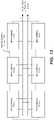
- FIG. 9is a simplified block diagram illustrating energy generation system 900 for providing AC power to a multi-phase AC grid or multi-phase back-up loads, according to embodiments of the present disclosure.
- Energy generation system 900may include three subsystems: subsystem A, subsystem B, and subsystem C, where each subsystem is configured to provide AC power in each phase of the multiple phases. When combined, the three subsystems A, B, and C form a multi-phase system for providing multi-phase power.
- Multi-phase energy generation system 900may be particularly useful for large buildings that span across a large area or demand high amounts of power, or for buildings that are located in regions whose laws require three-phase power systems or that house equipment requiring three-phase power above a certain power level.
- Reactive power and power factor controlis where power stored in the micro-batteries from the PV modules can be used to support capacitive and/or inductive reactive power needed for grid voltage stabilization. There may be communication between the three subsystems to coordinate for proper phase balance/synchronization under three-phase AC grid or back-up loads.
- each subsystemmay be a single-phase energy generation system having a micro-battery including a DC-to-DC converter and a DC-to-AC inverter configured to output single-phase AC power converted from DC power generated from a respective PV module or discharged by an energy storage device of the micro-battery.
- micro-battery 906 acan be configured to receive DC power at an input of micro-battery 906 a and store the DC energy in its battery pack or convert the received DC power to single-phase AC power and output the converted single-phase AC power to AC grid 908 a or back-up loads 910 a , each operating at a corresponding single phase.
- Micro batteries 906 b - cmay be similar in operation to micro-battery 906 a , and micro-batteries 906 a - c may be similar in construction to micro-batteries 600 or 700 discussed herein with respect to FIGS. 6 and 7 , respectively.
- Outputted AC power from respective micro-batteries in subsystems A-Cmay be outputted to AC grid 908 a - c or back-up loads 910 a - c , respectively.
- Each respective AC gridcan operate in a phase corresponding to a respective subsystem.
- single-phase micro-battery 906 a in subsystem Amay be configured to output AC power in phase 1
- single-phase micro-battery 906 b in subsystem Bmay be configured to output AC power in phase 2
- single-phase micro-battery 906 c in subsystem Cmay be configured to output AC power in phase 3.
- back-up loads for each subsystemmay be different single phase and/or three phase loads in an installation site.
- back-up loads 910 amay be appliances in a kitchen
- back-up loads 910 bmay be devices in a bedroom
- back-up loads 910 cmay be lighting at the installation site.
- Phases of output AC power from subsystems A-Cmay be offset from one another accordingly (for example: 120 degree electrical for a three-phase system).
- micro-batteries 906 a - cmay need to be coordinated with one another such that no two micro-batteries are outputting in the same phase.
- each micro-batterycan communicate with one another via communication lines 912 and 913 .
- micro-battery 906 amay output AC power in phase 1, and may send a command to micro-battery 906 b to output AC power in phase 2, and a command to micro-battery 906 c to output AC power in phase 3.
- outputted AC power from subsystems A-Cmay form a multi-phase system including phases 1-3.
- FIG. 9illustrates communication lines 912 and 913 are arranged in a serial configuration
- embodiments of the disclosureneed not be so limited.
- Other embodimentsmay have communication lines 912 and 913 arranged in a parallel configuration, or any other suitable configuration suitable for allowing micro-batteries 906 a - c to communication with each other.
- FIG. 10is a simplified block diagram illustrating energy generation system 1000 including split single-phase micro-batteries for providing AC power to a single-phase AC grid or single-phase back-up loads, according to embodiments of the present disclosure.
- energy generation system 1000may include three subsystems: subsystem A, subsystem B, and subsystem C, where each subsystem is configured to provide AC power in each partial phase of the single phases. When combined, the three subsystems A, B, and C form a split-phase energy generation system for providing single-phase power.
- each subsystemmay be a partial-phase energy generation system having a micro-battery that includes a DC-to-DC converter and a DC-to-AC inverter configured to output partial-phase AC power converted from DC power generated from arrays of PV strings or discharged by an energy storage device.
- micro-battery 906 acan be configured to receive DC power at an input of micro-battery 906 a and store the DC energy in its battery pack or convert the received DC power to partial-phase AC power and output the converted partial-phase AC power to an AC bus for outputting to AC grid 1008 or back-up loads 1010 .
- Respective partial-phase AC power outputs from micro-batteries 1006 b and 1006 cmay combine in the AC bus to form a complete single-phase power that can be outputted to AC grid 1008 or back-up loads 1010 , each operating at the single phase.
- Micro batteries 1006 a - cmay be similar in operation to micro-battery 1006 a
- micro-batteries 1006 a - cmay be similar in construction to micro-batteries 600 or 700 discussed herein with respect to FIGS. 6 and 7 , respectively
- the partial phases of output AC power from subsystems A-Cmay be completely offset or in sync from one another.
- micro-batteries 1006 a - cmay need to be coordinated with one another such that no two micro-batteries are outputting in the same phase.
- each micro-batterycan communicate with one another via communication lines 1012 and 1013 .
- micro-battery 1006 amay output AC power in partial phase 1, and may send a command to micro-battery 1006 b to output AC power in partial phase 2, and a command to micro-battery 1006 c to output AC power in partial phase 3.
- outputted AC power from subsystems A-Cmay form a single-phase system including partial phases 1-3 when combined.
- Power from the micro-battery packsmay be interconnected for outputting power to an AC grid or back-up loads.
- individual output voltages from the battery packsmay aggregate and combine to output a larger voltage to the inverter by the mere virtue of their connection with one another and without requiring each micro-battery to boost its output voltage.
- the micro-batteriesmay be arranged in a serial connection as shown in FIG. 11 .
- FIG. 11illustrates a block diagram of micro-battery packs 1102 a - f for a micro-battery PV system (e.g., micro-battery PV systems 300 or 400 in FIGS. 3 and 4 , respectively) that are connected in a serial configuration, according to some embodiments of the present disclosure.
- Each battery pack 1102 a - fmay be positioned proximate to a respective PV module (not shown), similar to the position of battery packs 304 a - f with respect to PV modules 302 a - f in FIG. 3 .
- each micro-battery 1102 a - fcan include a DC-to-DC converter, a DC-to-AC inverter, and a battery pack, such as micro-batteries 600 and 700 in FIGS. 6 and 7 , respectively, for converting and storing energy.
- micro-batteries 1102 a - fmay be coupled together in a serial circuit arrangement such that positive and negative terminals for each micro-battery are coupled to opposite polarities of adjacent micro-batteries.
- the positive terminal of micro-battery 1102 fmay be coupled to the negative terminal of micro-battery 1102 e , whose positive terminal is coupled to the negative terminal of micro-battery 1102 d , and so on and so forth. Accordingly, voltage provided by each micro-battery 1102 a - f may be aggregated into a larger voltage by virtue of the serial connection.
- micro-batteries 1102 a - fBy connecting micro-batteries 1102 a - f in this serial arrangement, the output voltage of the system is greater than the output of each micro-battery individually. Thus, the output voltage of each micro-battery is naturally stepped up by the mere nature of the serial connection.
- Such PV systemsrequire fewer components, are less complex to operate, and have less voltage conversions, which increases efficiency and lowers cost.
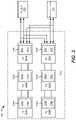
- FIG. 12is a block diagram illustrating micro-battery packs 1202 a - f for a micro-battery PV system (e.g., micro-battery PV systems 300 or 400 in FIGS. 3 and 4 , respectively) that are connected in a parallel configuration, according to some embodiments of the present disclosure.
- the positive terminals of micro-batteries 1202 a - fcan be coupled to a positive terminal bus, and the negative terminals can be coupled to a negative terminal bus.
- Coupling micro-batteries 1202 a - f in a parallel configurationcan increase the current/power output of the PV system for outputting to an AC grid or back-up loads.
- FIGS. 11 and 12illustrate only six micro-batteries for a corresponding string of PV modules, embodiments are not so limited. Other embodiments may have more or less micro-batteries, and at least as many PV modules than micro-batteries without departing from the spirit and scope of the present disclosure.
- each micro-batterycan communicate with adjacent micro-batteries via a plurality of communication lines (e.g., communication lines 1104 in FIG. 11 and communication lines 1204 in FIG. 12 ) represented by dotted and dashed lines, so that the micro-batteries can communicate with each other, such as to send instructions to, and receive status information from, each micro-battery.
- Micro-batteries 1102 a - fcan form a mesh network to communicate with one another.
- the communication linescan be wired (e.g., RS-485, RS-232, Modbus, CAN and the like) or wireless (e.g., PLC (power-line communication), Zigbee, RF, Bluetooth, Wi-Fi, and the like) communication lines.
Landscapes
- Engineering & Computer Science (AREA)
- Power Engineering (AREA)
- Charge And Discharge Circuits For Batteries Or The Like (AREA)
- Supply And Distribution Of Alternating Current (AREA)
Abstract
Description
Claims (14)
Priority Applications (1)
| Application Number | Priority Date | Filing Date | Title |
|---|---|---|---|
| US15/341,984US11309714B2 (en) | 2016-11-02 | 2016-11-02 | Micro-batteries for energy generation systems |
Applications Claiming Priority (1)
| Application Number | Priority Date | Filing Date | Title |
|---|---|---|---|
| US15/341,984US11309714B2 (en) | 2016-11-02 | 2016-11-02 | Micro-batteries for energy generation systems |
Publications (2)
| Publication Number | Publication Date |
|---|---|
| US20180123348A1 US20180123348A1 (en) | 2018-05-03 |
| US11309714B2true US11309714B2 (en) | 2022-04-19 |
Family
ID=62022633
Family Applications (1)
| Application Number | Title | Priority Date | Filing Date |
|---|---|---|---|
| US15/341,984Active2037-02-25US11309714B2 (en) | 2016-11-02 | 2016-11-02 | Micro-batteries for energy generation systems |
Country Status (1)
| Country | Link |
|---|---|
| US (1) | US11309714B2 (en) |
Cited By (1)
| Publication number | Priority date | Publication date | Assignee | Title |
|---|---|---|---|---|
| US20250119092A1 (en)* | 2019-12-30 | 2025-04-10 | Solaredge Technologies Ltd. | Energy Harvesting and Electrical Power Generation |
Families Citing this family (6)
| Publication number | Priority date | Publication date | Assignee | Title |
|---|---|---|---|---|
| US11594912B2 (en)* | 2017-04-24 | 2023-02-28 | King Fahd University Of Petroleum And Minerals | Smart energy management system for self-sufficient solar home |
| US10992139B1 (en)* | 2018-09-20 | 2021-04-27 | Farid Dibachi | Electrical power system |
| EP3912220A4 (en)* | 2019-01-16 | 2022-11-16 | Kiritz, Alexander | POWER SUPPLY CONTINUITY DEVICE |
| US11695297B2 (en) | 2020-05-20 | 2023-07-04 | Sunpower Corporation | Photovoltaic disconnect device for storage integration |
| WO2021242863A1 (en)* | 2020-05-29 | 2021-12-02 | Watershed Solar, Llc | Solar-energy electricity generation system with integrated load management |
| WO2023129480A1 (en)* | 2021-12-27 | 2023-07-06 | Electric Hydrogen Co. | Power supply system for an electrochemical stack |
Citations (118)
| Publication number | Priority date | Publication date | Assignee | Title |
|---|---|---|---|---|
| US3377539A (en) | 1966-06-29 | 1968-04-09 | Gulton Ind Inc | Polyphase inverter |
| US4183079A (en) | 1977-07-05 | 1980-01-08 | Sony Corporaton | DC-AC inverter |
| WO1982002134A1 (en) | 1980-12-09 | 1982-06-24 | Haulin Tord L | Pulse width modulated voltage converter for generating a preferably sinusoidal alternating voltage |
| US4488136A (en) | 1981-05-18 | 1984-12-11 | Westinghouse Electric Corp. | Combination transformer with common core portions |
| US4772994A (en) | 1987-09-10 | 1988-09-20 | Nishimu Electronics Industries, Co., Ltd. | Power source using high-frequency phase control |
| EP0340006A2 (en) | 1988-04-28 | 1989-11-02 | Matsushita Electric Industrial Co., Ltd. | Non-resonance AC power source apparatus |
| US5404059A (en) | 1992-03-19 | 1995-04-04 | Abb Patent Gmbh | Circuit for driving a voltage-controlled semiconductor switch |
| US5576941A (en) | 1994-08-10 | 1996-11-19 | York Technologies, Inc. | Modular power supply system |
| US5636107A (en) | 1995-11-15 | 1997-06-03 | International Power Devices, Inc. | DC-DC converters |
| US5726615A (en) | 1994-03-24 | 1998-03-10 | Bloom; Gordon E. | Integrated-magnetic apparatus |
| US5946206A (en) | 1997-02-17 | 1999-08-31 | Tdk Corporation | Plural parallel resonant switching power supplies |
| US5982645A (en) | 1992-08-25 | 1999-11-09 | Square D Company | Power conversion and distribution system |
| US6055169A (en) | 1998-04-24 | 2000-04-25 | Lucent Technologies Inc. | Current mode control circuit for paralleled power supply and method of operation thereof |
| WO2000070731A1 (en) | 1999-05-18 | 2000-11-23 | Nokia Corporation | Integrated direct current converter |
| US6211657B1 (en) | 2000-05-18 | 2001-04-03 | Communications & Power Industries, Inc. | Two stage power converter with interleaved buck regulators |
| US6307350B1 (en) | 1999-07-30 | 2001-10-23 | Ja Effect, Llc | Rechargeable direct current power source |
| US6311137B1 (en) | 1999-01-27 | 2001-10-30 | Canon Kabushiki Kaisha | Information display apparatus, information relay apparatus used in power generation system, information display method and information relay method, and information transmission method |
| US20010056330A1 (en) | 1997-11-24 | 2001-12-27 | Plug Power Inc., Delaware Corporation | Anti-islanding method and apparatus for distributed power generation |
| US6335871B1 (en) | 1994-10-03 | 2002-01-01 | Mitsubishi Denki Kabushiki Kaisha | Motor operation controller and insulation type bidirectional DC voltage converter |
| US6445599B1 (en) | 2001-03-29 | 2002-09-03 | Maxim Integrated Products, Inc. | Ripple canceling, soft switching isolated DC/DC converters with reduced voltage stress synchronous rectification |
| WO2002078164A1 (en) | 2001-03-09 | 2002-10-03 | Fronius International Gmbh | Method for regulating an inverter system |
| US20030185026A1 (en) | 2002-03-27 | 2003-10-02 | Shindengen Electric Manufacturing Co., Ltd. | DC power supply device with constant power output level |
| JP2003289674A (en) | 2002-03-27 | 2003-10-10 | Tama Tlo Kk | Inverter circuit and photovoltaic generator |
| US20040145928A1 (en) | 2003-01-23 | 2004-07-29 | Yokogawa Electric Corporation | Switching power supply |
| US20040189432A1 (en) | 2001-10-12 | 2004-09-30 | Liang Yan | Integrated magnetics for a dc-dc converter with flexible output inductor |
| US20040190314A1 (en) | 2003-02-05 | 2004-09-30 | Koji Yoshida | Switching power supply and control method for the same |
| US20040233685A1 (en) | 2003-02-06 | 2004-11-25 | Matsushita Electric Industrial Co., Ltd. | Switching power supply |
| US6888728B2 (en) | 2001-05-25 | 2005-05-03 | Tdk Corporation | Switching power supply unit |
| US20060083039A1 (en) | 2003-01-31 | 2006-04-20 | Oliveira Marcos P D | Power supply system with single phase or multiple phase inverters operating in parallel |
| GB2419968A (en) | 2004-11-08 | 2006-05-10 | Enecsys Ltd | Regulating the voltage fed to a power converter |
| WO2006089778A2 (en) | 2005-02-26 | 2006-08-31 | Kostal Industrie Elektrik Gmbh | Inverter |
| US20070133241A1 (en) | 2003-05-06 | 2007-06-14 | Asim Mumtaz | Power supply circuits |
| WO2007080429A2 (en) | 2006-01-13 | 2007-07-19 | Enecsys Limited | Power conditioning unit |
| US20070164612A1 (en) | 2004-01-09 | 2007-07-19 | Koninkijke Phillips Electronics N.V. | Decentralized power generation system |
| WO2007111018A1 (en) | 2006-03-27 | 2007-10-04 | Mitsubishi Electric Corporation | Power converter |
| US20070290656A1 (en) | 2006-06-16 | 2007-12-20 | Astec Custom Power ( Hk) Ltd. | Zero voltage zero current switching converter |
| JP2008278588A (en) | 2007-04-26 | 2008-11-13 | Nippon Oil Corp | Disaster response distributed power supply system and operation method of power conditioner |
| US7471524B1 (en) | 2006-05-26 | 2008-12-30 | University Of Central Florida Research Foundation, Inc. | Isolated DC-DC converters with high current capability |
| US20090066291A1 (en) | 2007-09-10 | 2009-03-12 | Jenn-Yang Tien | Distributed energy storage control system |
| US7518886B1 (en) | 2005-02-18 | 2009-04-14 | Virginia Tech Intellectual Properties, Inc. | Multiphase soft switched DC/DC converter and active control technique for fuel cell ripple current elimination |
| EP2056438A2 (en) | 2007-10-29 | 2009-05-06 | TDK Corporation | Switching power supply |
| US20090168461A1 (en) | 2007-12-27 | 2009-07-02 | Tdk Corporation | Switching power supply unit |
| DE102008056256A1 (en) | 2008-11-06 | 2010-05-20 | Siemens Aktiengesellschaft | Parallel inverter circuit use as energy source of photovoltaic system, has parallelly connected inverters with power semiconductors for supplying energy to power grid, where power semiconductors are synchronously controlled |
| US7728708B2 (en) | 2006-04-19 | 2010-06-01 | Sumida Corporation | Transformer apparatus, inverter transformer, and drive circuit |
| US7800247B2 (en) | 2008-05-30 | 2010-09-21 | Chun-Chieh Chang | Storage system that maximizes the utilization of renewable energy |
| US7804193B2 (en) | 2007-03-28 | 2010-09-28 | Delta Electronics, Inc. | Energy recycle system for use with AC current power supply |
| WO2010119324A2 (en) | 2009-04-16 | 2010-10-21 | Toyota Jidosha Kabushiki Kaisha | Onboard multiphase converter |
| US20110007527A1 (en) | 2009-07-07 | 2011-01-13 | Delta Electronics, Inc. | Multi-phase switching power conversion circuit |
| US20110051468A1 (en) | 2008-10-30 | 2011-03-03 | Sanken Electric Co., Ltd. | Switching power-supply apparatus |
| US20110080044A1 (en)* | 2009-09-04 | 2011-04-07 | Voltwerk Electronics Gmbh | Standalone unit of a standalone power grid for communicating energy requests with another standalone unit |
| CN102088190A (en) | 2009-12-03 | 2011-06-08 | 三星Sdi株式会社 | Grid-connected power storage system and method for controlling grid-connected power storage system |
| US20110133552A1 (en) | 2009-12-01 | 2011-06-09 | Yaron Binder | Dual Use Photovoltaic System |
| US20110144822A1 (en)* | 2009-12-15 | 2011-06-16 | Samsung Sdi Co., Ltd. | Grid-connected energy storage system and method of controlling grid-connected energy storage system |
| WO2011101030A1 (en) | 2010-02-17 | 2011-08-25 | Abb Research Ltd | An electric power plant and a method for control thereof |
| US20110204635A1 (en) | 2010-12-21 | 2011-08-25 | Nicholas Wright Miller | System and method for controlling wind turbine power output |
| EP2365599A1 (en) | 2010-03-08 | 2011-09-14 | SMA Solar Technology AG | Device for converting electrical energy and method for operating such a device |
| US20110232714A1 (en) | 2010-03-23 | 2011-09-29 | Vijay Bhavaraju | Power conversion system and method providing maximum efficiency of power conversion for a photovoltaic system, and photovoltaic system employing a photovoltaic array and an energy storage device |
| CN102290828A (en) | 2011-08-12 | 2011-12-21 | 广州智光电气股份有限公司 | Cascaded photovoltaic grid-connected inverter and control method |
| WO2011162025A1 (en) | 2010-06-22 | 2011-12-29 | シャープ株式会社 | Dc power distribution system |
| US20120019074A1 (en) | 2011-09-29 | 2012-01-26 | Sunlight Photonics Inc. | Methods and apparatus for high-frequency electrical power collection and transfer |
| US20120063177A1 (en) | 2011-03-22 | 2012-03-15 | Paul Garrity | Solar Photovoltaic Power Conditioning Units |
| US20120081937A1 (en) | 2010-09-30 | 2012-04-05 | Astec International Limited | Converters and Inverters for Photovoltaic Power Systems |
| WO2012043919A1 (en) | 2010-10-01 | 2012-04-05 | Samsung Sdi Co., Ltd. | Power conversion system for energy storage system and controlling method of the same |
| US20120153722A1 (en) | 2010-12-16 | 2012-06-21 | Ashot Nazarian | Method and apparatus for integrated electric power generation, storage and supply distributed and networked at the same time |
| CN102630361A (en) | 2009-11-25 | 2012-08-08 | 夏普株式会社 | Power conversion apparatus, power generating system, and charge/discharge control method |
| CN102638187A (en) | 2012-02-08 | 2012-08-15 | 苏州达方电子有限公司 | Off-grid master-slave type solar current converter system and control method thereof |
| US20120212065A1 (en)* | 2011-02-15 | 2012-08-23 | George Shu-Xing Cheng | Scalable and redundant mini-inverters |
| US20120228935A1 (en)* | 2010-03-30 | 2012-09-13 | Sanyo Electric Co., Ltd. | Electric power generation system, method of controlling a battery and computer-readable recording medium |
| US20120249078A1 (en) | 2011-03-31 | 2012-10-04 | Samsung Sdi Co., Ltd. | Battery system and energy storage system including the same |
| US20120262953A1 (en) | 2011-04-12 | 2012-10-18 | Flextronics Ap, Llc | Multi-phase resonant converter |
| US8338987B2 (en) | 2010-02-26 | 2012-12-25 | General Electric Company | Power generation frequency control |
| US20120326504A1 (en)* | 2011-06-27 | 2012-12-27 | Bloom Energy Corporation | B-Side Feed for Critical Power Applications |
| US8369113B2 (en) | 2004-11-08 | 2013-02-05 | Enecsys Limited | Power conditioning unit |
| US8410889B2 (en) | 2011-11-03 | 2013-04-02 | Enecsys Limited | Transformer construction |
| CN103036243A (en) | 2011-10-10 | 2013-04-10 | 三星Sdi株式会社 | Energy storage system and controlling method of the same |
| US20130106196A1 (en) | 2011-10-27 | 2013-05-02 | Sunpower Corporation | Master-slave architecture for controlling operation of photovoltaic power plants |
| GB2491494B (en) | 2011-03-22 | 2013-05-08 | Enecsys Ltd | Solar photovoltaic power conditioning units |
| US20130134782A1 (en) | 2011-11-29 | 2013-05-30 | Lsis Co., Ltd | Solar device |
| CN103155334A (en) | 2010-09-10 | 2013-06-12 | 三星Sdi株式会社 | Energy storage system and controlling method of the same |
| US20130181527A1 (en) | 2011-07-11 | 2013-07-18 | Shibashis Bhowmik | Systems and methods for solar photovoltaic energy collection and conversion |
| US20130187473A1 (en) | 2012-01-24 | 2013-07-25 | Infineon Technologies Austria Ag | Power Converter Circuit |
| US20130207466A1 (en)* | 2012-02-09 | 2013-08-15 | Electronics And Telecommunications Research Institute | Home energy management apparatus and method for interworking with new renewable energy |
| US20130234518A1 (en)* | 2003-05-06 | 2013-09-12 | Enecsys Limited | Power Supply Circuits |
| US20130260198A1 (en) | 2012-03-29 | 2013-10-03 | Hitachi, Ltd. | Battery System |
| US20130328397A1 (en)* | 2012-06-11 | 2013-12-12 | Samsung Sdi Co., Ltd. | Energy storage system |
| US20140015326A1 (en) | 2011-03-16 | 2014-01-16 | Sma Solar Technology Ag | Grid-connected inverter, inverter arrangement and method for operating an inverter arrangement |
| US8633670B2 (en) | 2009-12-15 | 2014-01-21 | Samsung Sdi Co., Ltd. | Reconfigurable energy storage system |
| WO2014020645A1 (en) | 2012-07-31 | 2014-02-06 | 三洋電機株式会社 | Power supply system and slave power storage system |
| US20140062198A1 (en) | 2011-05-11 | 2014-03-06 | Altenergy Power System, Inc. | Solar photovoltaic three-phase micro-inverter and a solar photovoltaic generation system |
| US8674668B2 (en) | 2010-06-07 | 2014-03-18 | Enecsys Limited | Solar photovoltaic systems |
| US20140079960A1 (en) | 2012-09-14 | 2014-03-20 | Samsung Sdi Co., Ltd. | Battery system and energy storage system |
| US20140077768A1 (en) | 2011-09-07 | 2014-03-20 | Samsung Sdi Co., Ltd. | Communication method, communication system, and energy storage system including the same |
| US20140117756A1 (en)* | 2012-10-30 | 2014-05-01 | Hitachi Information & Telecommunication Engineering, Ltd. | Power storage system and power source system |
| CN103904681A (en) | 2014-03-11 | 2014-07-02 | 西安理工大学 | High-power centralized type grid-connected photovoltaic power generation coordinated control system and method |
| US20140203649A1 (en) | 2013-01-18 | 2014-07-24 | 3L Power Llc | Method and Apparatus for Integrating a Secondary Power Source into a Power Generation Plant |
| US20140217827A1 (en)* | 2013-02-01 | 2014-08-07 | 3L Power Llc | Apparatus for and method of operation of a power inverter system |
| WO2014192015A2 (en) | 2013-05-03 | 2014-12-04 | Indian Institute Of Technology Bombay | Method and system for a multiport modular pv inverter |
| US20150008864A2 (en) | 2011-10-15 | 2015-01-08 | James Frederick Wolter | Distributed energy storage and power quality control in photovoltaic arrays |
| US20150021998A1 (en) | 2013-07-18 | 2015-01-22 | Solantro Semiconductor Corp. | Stabilized power generation |
| US20150076903A1 (en) | 2013-09-19 | 2015-03-19 | Kabushiki Kaisha Toshiba | Controlling apparatus, power converting apparatus, controlling method, computer-readable recording medium and controlling system |
| WO2015041249A1 (en) | 2013-09-20 | 2015-03-26 | 新神戸電機株式会社 | Power storage system and method of maintaining power storage system |
| US20150092453A1 (en) | 2013-09-30 | 2015-04-02 | Sanken Electric Co., Ltd. | Current resonance type power supply device |
| US9048353B2 (en) | 2008-07-01 | 2015-06-02 | Perfect Galaxy International Limited | Photovoltaic DC/DC micro-converter |
| US20150171766A1 (en)* | 2011-08-12 | 2015-06-18 | Massimo Valiani | Control of Leakage Currents in Systems with a Plurality of Parallel Inverters |
| US20150180232A1 (en)* | 2013-03-15 | 2015-06-25 | Fuji Electric Co., Ltd. | Uninterruptible power supply system |
| US9082897B2 (en) | 2010-12-29 | 2015-07-14 | Tsinghua University | Solar power storage module, and solar power storage system and solar power supply system having same |
| US20150288185A1 (en)* | 2012-12-10 | 2015-10-08 | Sma Solar Technology Ag | Security concept for integrating a battery into an inverter |
| US20150381074A1 (en) | 2013-07-29 | 2015-12-31 | Rhombus Energy Solutions, Inc. | Dc source-to-ac grid tie-in power enhancement using multilevel/multiphase inverter topology and resonant matrix tank converter |
| US9236790B2 (en) | 2009-10-02 | 2016-01-12 | Panasonic Corporation | Power distribution device and power distribution system using same |
| US20160111915A1 (en)* | 2013-05-22 | 2016-04-21 | Blue Solutions | Installation for restoring power to equipment to be supplied with power, particularly an electric vehicle |
| US9331499B2 (en) | 2010-08-18 | 2016-05-03 | Volterra Semiconductor LLC | System, method, module, and energy exchanger for optimizing output of series-connected photovoltaic and electrochemical devices |
| US9368964B2 (en) | 2006-12-06 | 2016-06-14 | Solaredge Technologies Ltd. | Distributed power system using direct current power sources |
| US20160226252A1 (en) | 2015-02-02 | 2016-08-04 | Technology Research, Llc | Interface for renewable energy system |
| US9444397B2 (en) | 2012-10-26 | 2016-09-13 | Sunculture Solar, Inc. | Integrated solar panel |
| US20170047742A1 (en) | 2015-08-14 | 2017-02-16 | Solarcity Corporation | Multi-phase inverter power control systems in an energy generation system |
| US20170331293A1 (en)* | 2016-05-10 | 2017-11-16 | Solarcity Corporation | Power control system with fault detection and data retention for energy generation systems |
| US20180248376A1 (en)* | 2015-10-28 | 2018-08-30 | Panasonic Intellectual Property Management Co., Ltd. | Power conversion system and control device |
| US20190109458A1 (en)* | 2016-03-29 | 2019-04-11 | Tabuchi Electric Co., Ltd. | Power conditioner, power supply system, and current control method |
- 2016
- 2016-11-02USUS15/341,984patent/US11309714B2/enactiveActive
Patent Citations (142)
| Publication number | Priority date | Publication date | Assignee | Title |
|---|---|---|---|---|
| US3377539A (en) | 1966-06-29 | 1968-04-09 | Gulton Ind Inc | Polyphase inverter |
| US4183079A (en) | 1977-07-05 | 1980-01-08 | Sony Corporaton | DC-AC inverter |
| WO1982002134A1 (en) | 1980-12-09 | 1982-06-24 | Haulin Tord L | Pulse width modulated voltage converter for generating a preferably sinusoidal alternating voltage |
| US4488136A (en) | 1981-05-18 | 1984-12-11 | Westinghouse Electric Corp. | Combination transformer with common core portions |
| US4772994A (en) | 1987-09-10 | 1988-09-20 | Nishimu Electronics Industries, Co., Ltd. | Power source using high-frequency phase control |
| EP0340006A2 (en) | 1988-04-28 | 1989-11-02 | Matsushita Electric Industrial Co., Ltd. | Non-resonance AC power source apparatus |
| US5404059A (en) | 1992-03-19 | 1995-04-04 | Abb Patent Gmbh | Circuit for driving a voltage-controlled semiconductor switch |
| US5982645A (en) | 1992-08-25 | 1999-11-09 | Square D Company | Power conversion and distribution system |
| US5726615A (en) | 1994-03-24 | 1998-03-10 | Bloom; Gordon E. | Integrated-magnetic apparatus |
| US5576941A (en) | 1994-08-10 | 1996-11-19 | York Technologies, Inc. | Modular power supply system |
| US6335871B1 (en) | 1994-10-03 | 2002-01-01 | Mitsubishi Denki Kabushiki Kaisha | Motor operation controller and insulation type bidirectional DC voltage converter |
| US5636107A (en) | 1995-11-15 | 1997-06-03 | International Power Devices, Inc. | DC-DC converters |
| US5946206A (en) | 1997-02-17 | 1999-08-31 | Tdk Corporation | Plural parallel resonant switching power supplies |
| US20010056330A1 (en) | 1997-11-24 | 2001-12-27 | Plug Power Inc., Delaware Corporation | Anti-islanding method and apparatus for distributed power generation |
| US6055169A (en) | 1998-04-24 | 2000-04-25 | Lucent Technologies Inc. | Current mode control circuit for paralleled power supply and method of operation thereof |
| US6311137B1 (en) | 1999-01-27 | 2001-10-30 | Canon Kabushiki Kaisha | Information display apparatus, information relay apparatus used in power generation system, information display method and information relay method, and information transmission method |
| WO2000070731A1 (en) | 1999-05-18 | 2000-11-23 | Nokia Corporation | Integrated direct current converter |
| US6807069B2 (en) | 1999-05-18 | 2004-10-19 | Nokia Corporation | Direct current converter with integrated transformer windings and output voltage filtering coils on the same magnetic core |
| US6307350B1 (en) | 1999-07-30 | 2001-10-23 | Ja Effect, Llc | Rechargeable direct current power source |
| US6211657B1 (en) | 2000-05-18 | 2001-04-03 | Communications & Power Industries, Inc. | Two stage power converter with interleaved buck regulators |
| WO2002078164A1 (en) | 2001-03-09 | 2002-10-03 | Fronius International Gmbh | Method for regulating an inverter system |
| US20040076028A1 (en) | 2001-03-09 | 2004-04-22 | Gunter Achleitner | Method for regulating an inverter system |
| US6445599B1 (en) | 2001-03-29 | 2002-09-03 | Maxim Integrated Products, Inc. | Ripple canceling, soft switching isolated DC/DC converters with reduced voltage stress synchronous rectification |
| US6888728B2 (en) | 2001-05-25 | 2005-05-03 | Tdk Corporation | Switching power supply unit |
| US20040189432A1 (en) | 2001-10-12 | 2004-09-30 | Liang Yan | Integrated magnetics for a dc-dc converter with flexible output inductor |
| JP2003289674A (en) | 2002-03-27 | 2003-10-10 | Tama Tlo Kk | Inverter circuit and photovoltaic generator |
| US20030185026A1 (en) | 2002-03-27 | 2003-10-02 | Shindengen Electric Manufacturing Co., Ltd. | DC power supply device with constant power output level |
| US20040145928A1 (en) | 2003-01-23 | 2004-07-29 | Yokogawa Electric Corporation | Switching power supply |
| US20060083039A1 (en) | 2003-01-31 | 2006-04-20 | Oliveira Marcos P D | Power supply system with single phase or multiple phase inverters operating in parallel |
| US20040190314A1 (en) | 2003-02-05 | 2004-09-30 | Koji Yoshida | Switching power supply and control method for the same |
| US20040233685A1 (en) | 2003-02-06 | 2004-11-25 | Matsushita Electric Industrial Co., Ltd. | Switching power supply |
| US20130234518A1 (en)* | 2003-05-06 | 2013-09-12 | Enecsys Limited | Power Supply Circuits |
| US20070133241A1 (en) | 2003-05-06 | 2007-06-14 | Asim Mumtaz | Power supply circuits |
| US20070164612A1 (en) | 2004-01-09 | 2007-07-19 | Koninkijke Phillips Electronics N.V. | Decentralized power generation system |
| GB2419968A (en) | 2004-11-08 | 2006-05-10 | Enecsys Ltd | Regulating the voltage fed to a power converter |
| US8369113B2 (en) | 2004-11-08 | 2013-02-05 | Enecsys Limited | Power conditioning unit |
| US7518886B1 (en) | 2005-02-18 | 2009-04-14 | Virginia Tech Intellectual Properties, Inc. | Multiphase soft switched DC/DC converter and active control technique for fuel cell ripple current elimination |
| US20070217239A1 (en) | 2005-02-26 | 2007-09-20 | Kostal Industrie Elektrik Gmbh | Inverter |
| WO2006089778A2 (en) | 2005-02-26 | 2006-08-31 | Kostal Industrie Elektrik Gmbh | Inverter |
| WO2007080429A2 (en) | 2006-01-13 | 2007-07-19 | Enecsys Limited | Power conditioning unit |
| WO2007111018A1 (en) | 2006-03-27 | 2007-10-04 | Mitsubishi Electric Corporation | Power converter |
| US7728708B2 (en) | 2006-04-19 | 2010-06-01 | Sumida Corporation | Transformer apparatus, inverter transformer, and drive circuit |
| US7471524B1 (en) | 2006-05-26 | 2008-12-30 | University Of Central Florida Research Foundation, Inc. | Isolated DC-DC converters with high current capability |
| US20070290656A1 (en) | 2006-06-16 | 2007-12-20 | Astec Custom Power ( Hk) Ltd. | Zero voltage zero current switching converter |
| US9368964B2 (en) | 2006-12-06 | 2016-06-14 | Solaredge Technologies Ltd. | Distributed power system using direct current power sources |
| US20160241079A1 (en) | 2006-12-06 | 2016-08-18 | Solaredge Technologies Ltd. | Distributed power system using direct current power sources |
| US7804193B2 (en) | 2007-03-28 | 2010-09-28 | Delta Electronics, Inc. | Energy recycle system for use with AC current power supply |
| JP2008278588A (en) | 2007-04-26 | 2008-11-13 | Nippon Oil Corp | Disaster response distributed power supply system and operation method of power conditioner |
| US20090066291A1 (en) | 2007-09-10 | 2009-03-12 | Jenn-Yang Tien | Distributed energy storage control system |
| EP2056438A2 (en) | 2007-10-29 | 2009-05-06 | TDK Corporation | Switching power supply |
| US20090168461A1 (en) | 2007-12-27 | 2009-07-02 | Tdk Corporation | Switching power supply unit |
| US7800247B2 (en) | 2008-05-30 | 2010-09-21 | Chun-Chieh Chang | Storage system that maximizes the utilization of renewable energy |
| CN102113194A (en) | 2008-05-30 | 2011-06-29 | 张惇杰 | A storage system that maximizes the use of renewable energy |
| US9048353B2 (en) | 2008-07-01 | 2015-06-02 | Perfect Galaxy International Limited | Photovoltaic DC/DC micro-converter |
| US20110051468A1 (en) | 2008-10-30 | 2011-03-03 | Sanken Electric Co., Ltd. | Switching power-supply apparatus |
| DE102008056256A1 (en) | 2008-11-06 | 2010-05-20 | Siemens Aktiengesellschaft | Parallel inverter circuit use as energy source of photovoltaic system, has parallelly connected inverters with power semiconductors for supplying energy to power grid, where power semiconductors are synchronously controlled |
| WO2010119324A2 (en) | 2009-04-16 | 2010-10-21 | Toyota Jidosha Kabushiki Kaisha | Onboard multiphase converter |
| US20110007527A1 (en) | 2009-07-07 | 2011-01-13 | Delta Electronics, Inc. | Multi-phase switching power conversion circuit |
| US20110080044A1 (en)* | 2009-09-04 | 2011-04-07 | Voltwerk Electronics Gmbh | Standalone unit of a standalone power grid for communicating energy requests with another standalone unit |
| US9236790B2 (en) | 2009-10-02 | 2016-01-12 | Panasonic Corporation | Power distribution device and power distribution system using same |
| CN102630361A (en) | 2009-11-25 | 2012-08-08 | 夏普株式会社 | Power conversion apparatus, power generating system, and charge/discharge control method |
| US20110133552A1 (en) | 2009-12-01 | 2011-06-09 | Yaron Binder | Dual Use Photovoltaic System |
| US20110133558A1 (en) | 2009-12-03 | 2011-06-09 | Jong-Ho Park | Grid-connected power storage system and method for controlling grid-connected power storage system |
| CN102088190A (en) | 2009-12-03 | 2011-06-08 | 三星Sdi株式会社 | Grid-connected power storage system and method for controlling grid-connected power storage system |
| US20110144822A1 (en)* | 2009-12-15 | 2011-06-16 | Samsung Sdi Co., Ltd. | Grid-connected energy storage system and method of controlling grid-connected energy storage system |
| US8633670B2 (en) | 2009-12-15 | 2014-01-21 | Samsung Sdi Co., Ltd. | Reconfigurable energy storage system |
| US8716891B2 (en) | 2009-12-15 | 2014-05-06 | Samsung Sdi Co., Ltd. | Energy storage system connected to a grid and multiple power generation modules and method of controlling the same |
| WO2011101030A1 (en) | 2010-02-17 | 2011-08-25 | Abb Research Ltd | An electric power plant and a method for control thereof |
| US8338987B2 (en) | 2010-02-26 | 2012-12-25 | General Electric Company | Power generation frequency control |
| US8743570B2 (en) | 2010-03-08 | 2014-06-03 | Sma Solar Technology Ag | Apparatus for converting electric energy and method for operating such an apparatus |
| EP2365599A1 (en) | 2010-03-08 | 2011-09-14 | SMA Solar Technology AG | Device for converting electrical energy and method for operating such a device |
| US20110232714A1 (en) | 2010-03-23 | 2011-09-29 | Vijay Bhavaraju | Power conversion system and method providing maximum efficiency of power conversion for a photovoltaic system, and photovoltaic system employing a photovoltaic array and an energy storage device |
| US20120228935A1 (en)* | 2010-03-30 | 2012-09-13 | Sanyo Electric Co., Ltd. | Electric power generation system, method of controlling a battery and computer-readable recording medium |
| US8674668B2 (en) | 2010-06-07 | 2014-03-18 | Enecsys Limited | Solar photovoltaic systems |
| EP2587623B1 (en) | 2010-06-22 | 2016-06-29 | Sharp Kabushiki Kaisha | Dc power distribution system |
| WO2011162025A1 (en) | 2010-06-22 | 2011-12-29 | シャープ株式会社 | Dc power distribution system |
| US9331499B2 (en) | 2010-08-18 | 2016-05-03 | Volterra Semiconductor LLC | System, method, module, and energy exchanger for optimizing output of series-connected photovoltaic and electrochemical devices |
| CN103155334A (en) | 2010-09-10 | 2013-06-12 | 三星Sdi株式会社 | Energy storage system and controlling method of the same |
| US20120081937A1 (en) | 2010-09-30 | 2012-04-05 | Astec International Limited | Converters and Inverters for Photovoltaic Power Systems |
| WO2012043919A1 (en) | 2010-10-01 | 2012-04-05 | Samsung Sdi Co., Ltd. | Power conversion system for energy storage system and controlling method of the same |
| CN103155335A (en) | 2010-10-01 | 2013-06-12 | 三星Sdi株式会社 | Power conversion system for energy storage system and controlling method of the same |
| US20130181519A1 (en) | 2010-10-01 | 2013-07-18 | Woog-Young Lee | Power conversion system for energy storage system and controlling method of the same |
| US20120153722A1 (en) | 2010-12-16 | 2012-06-21 | Ashot Nazarian | Method and apparatus for integrated electric power generation, storage and supply distributed and networked at the same time |
| US20110204635A1 (en) | 2010-12-21 | 2011-08-25 | Nicholas Wright Miller | System and method for controlling wind turbine power output |
| US9082897B2 (en) | 2010-12-29 | 2015-07-14 | Tsinghua University | Solar power storage module, and solar power storage system and solar power supply system having same |
| US20120212065A1 (en)* | 2011-02-15 | 2012-08-23 | George Shu-Xing Cheng | Scalable and redundant mini-inverters |
| US20140015326A1 (en) | 2011-03-16 | 2014-01-16 | Sma Solar Technology Ag | Grid-connected inverter, inverter arrangement and method for operating an inverter arrangement |
| US8934269B2 (en) | 2011-03-22 | 2015-01-13 | Enecsys Limited | Solar photovoltaic power conditioning units |
| GB2486509A (en) | 2011-03-22 | 2012-06-20 | Enecsys Ltd | Photovoltaic power conditioning unit having transformer with integrated output inductor |
| US20170133943A1 (en) | 2011-03-22 | 2017-05-11 | Solarcity Corporation | Solar photovoltaic power conditioning units |
| US20150256092A1 (en) | 2011-03-22 | 2015-09-10 | Enecsys Limited | Solar photovoltaic power conditioning units |
| GB2491494B (en) | 2011-03-22 | 2013-05-08 | Enecsys Ltd | Solar photovoltaic power conditioning units |
| US10424936B2 (en) | 2011-03-22 | 2019-09-24 | Tesla, Inc. | Solar photovoltaic power conditioning units |
| US20130229842A1 (en) | 2011-03-22 | 2013-09-05 | Enecsys Limited | Solar Photovoltaic Power Conditioning Units |
| WO2012127208A2 (en) | 2011-03-22 | 2012-09-27 | Enecsys Limited | Solar photovoltaic power conditioning units |
| US20120063177A1 (en) | 2011-03-22 | 2012-03-15 | Paul Garrity | Solar Photovoltaic Power Conditioning Units |
| US8391031B2 (en) | 2011-03-22 | 2013-03-05 | Enecsys Limited | Solar photovoltaic power conditioning units |
| EP2689525A2 (en) | 2011-03-22 | 2014-01-29 | Enecsys Limited | Arrangement for controlled and efficient infeed of photovoltaic power into the ac mains with parallely connected dc/dc converters |
| US20120249078A1 (en) | 2011-03-31 | 2012-10-04 | Samsung Sdi Co., Ltd. | Battery system and energy storage system including the same |
| US20120262953A1 (en) | 2011-04-12 | 2012-10-18 | Flextronics Ap, Llc | Multi-phase resonant converter |
| US20140062198A1 (en) | 2011-05-11 | 2014-03-06 | Altenergy Power System, Inc. | Solar photovoltaic three-phase micro-inverter and a solar photovoltaic generation system |
| US20120326504A1 (en)* | 2011-06-27 | 2012-12-27 | Bloom Energy Corporation | B-Side Feed for Critical Power Applications |
| US20130181527A1 (en) | 2011-07-11 | 2013-07-18 | Shibashis Bhowmik | Systems and methods for solar photovoltaic energy collection and conversion |
| CN102290828A (en) | 2011-08-12 | 2011-12-21 | 广州智光电气股份有限公司 | Cascaded photovoltaic grid-connected inverter and control method |
| US20150171766A1 (en)* | 2011-08-12 | 2015-06-18 | Massimo Valiani | Control of Leakage Currents in Systems with a Plurality of Parallel Inverters |
| US20140077768A1 (en) | 2011-09-07 | 2014-03-20 | Samsung Sdi Co., Ltd. | Communication method, communication system, and energy storage system including the same |
| US20120019074A1 (en) | 2011-09-29 | 2012-01-26 | Sunlight Photonics Inc. | Methods and apparatus for high-frequency electrical power collection and transfer |
| CN103036243A (en) | 2011-10-10 | 2013-04-10 | 三星Sdi株式会社 | Energy storage system and controlling method of the same |
| US20150008864A2 (en) | 2011-10-15 | 2015-01-08 | James Frederick Wolter | Distributed energy storage and power quality control in photovoltaic arrays |
| US20130106196A1 (en) | 2011-10-27 | 2013-05-02 | Sunpower Corporation | Master-slave architecture for controlling operation of photovoltaic power plants |
| US8410889B2 (en) | 2011-11-03 | 2013-04-02 | Enecsys Limited | Transformer construction |
| US20130134782A1 (en) | 2011-11-29 | 2013-05-30 | Lsis Co., Ltd | Solar device |
| US20130187473A1 (en) | 2012-01-24 | 2013-07-25 | Infineon Technologies Austria Ag | Power Converter Circuit |
| US20130201737A1 (en) | 2012-02-08 | 2013-08-08 | Darfon Electronics Corp. | Off-grid master-slave solar inverter system and method thereof |
| CN102638187A (en) | 2012-02-08 | 2012-08-15 | 苏州达方电子有限公司 | Off-grid master-slave type solar current converter system and control method thereof |
| US20130207466A1 (en)* | 2012-02-09 | 2013-08-15 | Electronics And Telecommunications Research Institute | Home energy management apparatus and method for interworking with new renewable energy |
| US20130260198A1 (en) | 2012-03-29 | 2013-10-03 | Hitachi, Ltd. | Battery System |
| US20130328397A1 (en)* | 2012-06-11 | 2013-12-12 | Samsung Sdi Co., Ltd. | Energy storage system |
| WO2014020645A1 (en) | 2012-07-31 | 2014-02-06 | 三洋電機株式会社 | Power supply system and slave power storage system |
| US20140079960A1 (en) | 2012-09-14 | 2014-03-20 | Samsung Sdi Co., Ltd. | Battery system and energy storage system |
| US9444397B2 (en) | 2012-10-26 | 2016-09-13 | Sunculture Solar, Inc. | Integrated solar panel |
| US20140117756A1 (en)* | 2012-10-30 | 2014-05-01 | Hitachi Information & Telecommunication Engineering, Ltd. | Power storage system and power source system |
| US20150288185A1 (en)* | 2012-12-10 | 2015-10-08 | Sma Solar Technology Ag | Security concept for integrating a battery into an inverter |
| US20140203649A1 (en) | 2013-01-18 | 2014-07-24 | 3L Power Llc | Method and Apparatus for Integrating a Secondary Power Source into a Power Generation Plant |
| US20140217827A1 (en)* | 2013-02-01 | 2014-08-07 | 3L Power Llc | Apparatus for and method of operation of a power inverter system |
| US20150180232A1 (en)* | 2013-03-15 | 2015-06-25 | Fuji Electric Co., Ltd. | Uninterruptible power supply system |
| WO2014192015A2 (en) | 2013-05-03 | 2014-12-04 | Indian Institute Of Technology Bombay | Method and system for a multiport modular pv inverter |
| US20160111915A1 (en)* | 2013-05-22 | 2016-04-21 | Blue Solutions | Installation for restoring power to equipment to be supplied with power, particularly an electric vehicle |
| US20150021998A1 (en) | 2013-07-18 | 2015-01-22 | Solantro Semiconductor Corp. | Stabilized power generation |
| US20150381074A1 (en) | 2013-07-29 | 2015-12-31 | Rhombus Energy Solutions, Inc. | Dc source-to-ac grid tie-in power enhancement using multilevel/multiphase inverter topology and resonant matrix tank converter |
| US20150076903A1 (en) | 2013-09-19 | 2015-03-19 | Kabushiki Kaisha Toshiba | Controlling apparatus, power converting apparatus, controlling method, computer-readable recording medium and controlling system |
| US20160233560A1 (en) | 2013-09-20 | 2016-08-11 | Hitachi Chemical Company, Ltd. | Power Storage System and Maintenance Method of the Power Storage System |
| WO2015041249A1 (en) | 2013-09-20 | 2015-03-26 | 新神戸電機株式会社 | Power storage system and method of maintaining power storage system |
| US20150092453A1 (en) | 2013-09-30 | 2015-04-02 | Sanken Electric Co., Ltd. | Current resonance type power supply device |
| CN103904681A (en) | 2014-03-11 | 2014-07-02 | 西安理工大学 | High-power centralized type grid-connected photovoltaic power generation coordinated control system and method |
| US20160226252A1 (en) | 2015-02-02 | 2016-08-04 | Technology Research, Llc | Interface for renewable energy system |
| US20170047740A1 (en) | 2015-08-14 | 2017-02-16 | Solarcity Corporation | Multiple inverter power control systems in an energy generation system |
| US20170047741A1 (en) | 2015-08-14 | 2017-02-16 | Solarcity Corporation | Multiple energy storage devices for inverter power control systems in an energy generation system |
| US20170047742A1 (en) | 2015-08-14 | 2017-02-16 | Solarcity Corporation | Multi-phase inverter power control systems in an energy generation system |
| US20180248376A1 (en)* | 2015-10-28 | 2018-08-30 | Panasonic Intellectual Property Management Co., Ltd. | Power conversion system and control device |
| US20190109458A1 (en)* | 2016-03-29 | 2019-04-11 | Tabuchi Electric Co., Ltd. | Power conditioner, power supply system, and current control method |
| US20170331293A1 (en)* | 2016-05-10 | 2017-11-16 | Solarcity Corporation | Power control system with fault detection and data retention for energy generation systems |
Non-Patent Citations (52)
| Title |
|---|
| Decision to Grant received for European Patent Application No. 12715705.5, dated Mar. 26, 2020, 2 pages. |
| Decision to Grant received for European Patent Application No. 16754636.5, dated Jul. 16, 2020, 2 pages. |
| Final Office Action received for U.S. Appl. No. 13/769,257, dated Mar. 20, 2014, 14 pages. |
| Final Office Action received for U.S. Appl. No. 14/537,032, dated Jan. 26, 2016, 18 pages. |
| Final Office Action received for U.S. Appl. No. 15/161,118, dated Feb. 7, 2019, 15 pages. |
| Final Office Action received for U.S. Appl. No. 15/161,118, dated Sep. 19, 2019, 16 pages. |
| Final Office Action received for U.S. Appl. No. 15/983,945, dated Apr. 8, 2019, 13 pages. |
| First Action Interview—Office Action received for U.S. Appl. No. 15/161,104, dated Sep. 14, 2018, 8 pages. |
| First Action Interview—Office Action received for U.S. Appl. No. 15/161,118, dated Sep. 25, 2018, 8 pages. |
| First Action Interview—Office Action received for U.S. Appl. No. 15/161,127, dated Sep. 20, 2018, 8 pages. |
| Intention to Grant received for European Patent Application No. 12715705.5, dated Oct. 14, 2019, 9 pages. |
| Intention to Grant received for European Patent Application No. 16754636.5, dated Mar. 3, 2020, 8 pages. |
| International Preliminary Report on Patentability received for PCT Patent Application No. PCT/GB2012/050515, dated Oct. 3, 2013, 16 pages. |
| International Preliminary Report on Patentability received for PCT Patent Application No. PCT/US2016/046921, dated Mar. 1, 2018, 7 pages. |
| International Preliminary Report on Patentability received for PCT Patent Application No. PCT/US2016/046926, dated Mar. 1, 2018, 7 pages. |
| International Preliminary Report on Patentability received for PCT Patent Application No. PCT/US2016/046927, dated Mar. 1, 2018, 9 pages. |
| International Search Report and Written Opinion received for PCT Patent Application No. PCT/GB2012/050515, dated Dec. 14, 2012, 19 pages. |
| International Search Report and Written Opinion received for PCT Patent Application No. PCT/US2016/046921, dated Nov. 18, 2016, 8 pages. |
| International Search Report and Written Opinion received for PCT Patent Application No. PCT/US2016/046926, dated Nov. 30, 2016, 8 pages. |
| International Search Report and Written Opinion received for PCT Patent Application No. PCT/US2016/046927, dated Oct. 24, 2016, 11 pages. |
| Mumtaz et al., "Grid Connected PV Inverter using a Commercially Available Power IC", PV in Europe Conference, 2002, 3 pages. |
| Non-Final Office Action received for U.S. Appl. No. 13/244,161, dated May 4, 2012, 14 pages. |
| Non-Final Office Action received for U.S. Appl. No. 13/769,257, dated Nov. 15, 2013, 14 pages. |
| Non-Final Office Action received for U.S. Appl. No. 14/537,032, dated Jun. 21, 2016, 18 pages. |
| Non-Final Office Action received for U.S. Appl. No. 14/537,032, dated Jun. 29, 2015, 21 pages. |
| Non-Final Office Action received for U.S. Appl. No. 15/161,118, dated May 30, 2019, 15 pages. |
| Non-Final Office Action received for U.S. Appl. No. 15/406,638, dated Oct. 19, 2017, 7 pages. |
| Non-Final Office Action received for U.S. Appl. No. 15/983,945, dated Dec. 18, 2018, 14 pages. |
| Notice of Allowance received for U.S. Appl. No. 13/244,161, dated Oct. 26, 2012, 7 pages. |
| Notice of Allowance received for U.S. Appl. No. 13/769,257, dated Aug. 4, 2014, 7 pages. |
| Notice of Allowance received for U.S. Appl. No. 14/537,032, dated Oct. 13, 2016, 8 pages. |
| Notice of Allowance received for U.S. Appl. No. 15/161,104, dated Jan. 22, 2019, 7 pages. |
| Notice of Allowance received for U.S. Appl. No. 15/161,118, dated Jan. 3, 2020, 5 pages. |
| Notice of Allowance received for U.S. Appl. No. 15/161,127, dated Dec. 4, 2018, 7 pages. |
| Notice of Allowance received for U.S. Appl. No. 15/406,638, dated Feb. 22, 2018, 7 pages. |
| Notice of Allowance received for U.S. Appl. No. 15/983,945, dated May 29, 2019, 7 pages. |
| Office Action received for Chinese Patent Application No. 201680047920.6, dated Apr. 2, 2021, 21 pages (10 pages of English Translation and 11 pages of Official Copy Only). |
| Office Action received for Chinese Patent Application No. 201680047920.6, dated Jun. 30, 2020, 12 pages (Official Copy Only) (See Communication under 37 CFR § 1.98(a) (3)). |
| Office Action received for Chinese Patent Application No. 201680047927.8, dated Jun. 3, 2021, 17 pages (9 pages of English Translation and 8 pages of Official Copy). |
| Office Action received for Chinese Patent Application No. 201680047927.8, dated Sep. 3, 2020, 9 pages (Official Copy Only) (See Communication under 37 CFR § 1.98(a) (3)). |
| Office Action received for Chinese Patent Application No. 201680047928.2, dated Sep. 3, 2020, 9 pages (Official Copy Only) (See Communication under 37 CFR § 1.98(a) (3)). |
| Office Action received for European Patent Application No. 12715705.5, dated Dec. 20, 2018, 13 pages. |
| Office Action received for European Patent Application No. 12715705.5, dated Jun. 14, 2018, 8 pages. |
| Office Action received for European Patent Application No. 12715705.5, dated Sep. 15, 2016, 14 pages. |
| Office Action received for European Patent Application No. 16754636.5, dated May 29, 2019, 5 pages. |
| Office Action received for European Patent Application No. 16754637.3, dated Dec. 11, 2019, 3 pages. |
| Office Action received for European Patent Application No. 16754637.3, dated May 28, 2019, 5 pages. |
| Office Action received for European Patent Application No. 16754638.1, dated Mar. 3, 2021, 4 pages. |
| Pre-Interview First Office Action received for U.S. Appl. No. 15/161,104, dated Jun. 29, 2018, 5 pages. |
| Pre-Interview First Office Action received for U.S. Appl. No. 15/161,118, dated Jun. 29, 2018, 5 pages. |
| Pre-Interview First Office Action received for U.S. Appl. No. 15/161,127, dated Jun. 29, 2018, 5 pages. |
| Varela et al., "Current Mode with RMS Voltage and Offset Control Loops for a Single-Phase Aircraft Inverter Suitable for Parallel and 3-Phase Operation Mode", Energy Conversion Congress and Exposition (ECCE), IEEE, 2011, pp. 2562-2567. |
Cited By (1)
| Publication number | Priority date | Publication date | Assignee | Title |
|---|---|---|---|---|
| US20250119092A1 (en)* | 2019-12-30 | 2025-04-10 | Solaredge Technologies Ltd. | Energy Harvesting and Electrical Power Generation |
Also Published As
| Publication number | Publication date |
|---|---|
| US20180123348A1 (en) | 2018-05-03 |
Similar Documents
| Publication | Publication Date | Title |
|---|---|---|
| US11309714B2 (en) | Micro-batteries for energy generation systems | |
| US10857897B2 (en) | Energy generation and storage system with electric vehicle charging capability | |
| EP3286820B1 (en) | Hybrid inverter power control system for pv string, battery, grid and back-up loads | |
| US10340702B2 (en) | Optimizer battery PV energy generation systems | |
| US10644510B2 (en) | Multiple energy storage devices for inverter power control systems in an energy generation system | |
| US10424933B2 (en) | Automatic smart transfer switch for energy generation systems | |
| US11809209B2 (en) | Systems and methods for electricity generation, storage, distribution, and dispatch | |
| US20160204480A1 (en) | Method and device for storing electrical energy in electrochemical energy accumulators | |
| US20220263311A1 (en) | System and Method for Managing Power | |
| WO2021051186A1 (en) | An apparatus, method and article for maximizing solar charge current through the use of split wire(s) in a solar array with solar panels connected in the combination of series and parallel | |
| Vetter et al. | Lithium-ion batteries for storage of renewable energies and electric grid backup | |
| Rahman et al. | EV charging in a commercial hybrid AC/DC microgrid: Configuration, control and impact analysis | |
| Abdelkarim et al. | Supersession of large penetration photovoltaic power transients using storage batteries | |
| Mendi et al. | Importance of Lithium-Ion Energy Storage Systems in Balancing the Grid: Case Study in Turkey | |
| Gouveia et al. | Microgrid Demonstration Projects and Pilot Sites | |
| Nurdiana et al. | Performance of 10 kWp PV rooftop system based on smart grid in energy building PUSPIPTEK | |
| JP7370850B2 (en) | Power supply system and substation equipment | |
| Lerens | MODELLING OF A MICROGRID IN A PUBLIC BUILDING | |
| Sites | Microgrid Demonstration Projects | |
| Chandra et al. | Study of operational modes of a grid connected solar power generation with storage battery | |
| Smee et al. | Autonomous solar supply for railway signalling | |
| Chawla | Residential Battery Energy Storage and Smart Grids |
Legal Events
| Date | Code | Title | Description |
|---|---|---|---|
| AS | Assignment | Owner name:SOLARCITY CORPORATION, CALIFORNIA Free format text:ASSIGNMENT OF ASSIGNORS INTEREST;ASSIGNOR:NARLA, SANDEEP;REEL/FRAME:040214/0468 Effective date:20161029 | |
| STPP | Information on status: patent application and granting procedure in general | Free format text:NON FINAL ACTION MAILED | |
| STPP | Information on status: patent application and granting procedure in general | Free format text:RESPONSE TO NON-FINAL OFFICE ACTION ENTERED AND FORWARDED TO EXAMINER | |
| STPP | Information on status: patent application and granting procedure in general | Free format text:FINAL REJECTION MAILED | |
| STPP | Information on status: patent application and granting procedure in general | Free format text:DOCKETED NEW CASE - READY FOR EXAMINATION | |
| STPP | Information on status: patent application and granting procedure in general | Free format text:NON FINAL ACTION MAILED | |
| STPP | Information on status: patent application and granting procedure in general | Free format text:NON FINAL ACTION MAILED | |
| AS | Assignment | Owner name:TESLA, INC., CALIFORNIA Free format text:ASSIGNMENT OF ASSIGNORS INTEREST;ASSIGNOR:SOLARCITY CORPORATION;REEL/FRAME:056172/0062 Effective date:20210316 | |
| STPP | Information on status: patent application and granting procedure in general | Free format text:RESPONSE TO NON-FINAL OFFICE ACTION ENTERED AND FORWARDED TO EXAMINER | |
| STPP | Information on status: patent application and granting procedure in general | Free format text:FINAL REJECTION MAILED | |
| STPP | Information on status: patent application and granting procedure in general | Free format text:RESPONSE AFTER FINAL ACTION FORWARDED TO EXAMINER | |
| STPP | Information on status: patent application and granting procedure in general | Free format text:AWAITING TC RESP., ISSUE FEE NOT PAID | |
| STPP | Information on status: patent application and granting procedure in general | Free format text:NOTICE OF ALLOWANCE MAILED -- APPLICATION RECEIVED IN OFFICE OF PUBLICATIONS | |
| STPP | Information on status: patent application and granting procedure in general | Free format text:PUBLICATIONS -- ISSUE FEE PAYMENT VERIFIED | |
| STCF | Information on status: patent grant | Free format text:PATENTED CASE |