US11309126B2 - Wireless power transmittal - Google Patents
Wireless power transmittalDownload PDFInfo
- Publication number
- US11309126B2 US11309126B2US17/107,184US202017107184AUS11309126B2US 11309126 B2US11309126 B2US 11309126B2US 202017107184 AUS202017107184 AUS 202017107184AUS 11309126 B2US11309126 B2US 11309126B2
- Authority
- US
- United States
- Prior art keywords
- primary coil
- coil
- primary
- power
- coils
- Prior art date
- Legal status (The legal status is an assumption and is not a legal conclusion. Google has not performed a legal analysis and makes no representation as to the accuracy of the status listed.)
- Active
Links
- 238000012546transferMethods0.000description15
- 230000005540biological transmissionEffects0.000description11
- 238000004891communicationMethods0.000description9
- 230000001939inductive effectEffects0.000description8
- 230000008901benefitEffects0.000description6
- 230000008878couplingEffects0.000description3
- 238000010168coupling processMethods0.000description3
- 238000005859coupling reactionMethods0.000description3
- 238000010586diagramMethods0.000description3
- 238000004146energy storageMethods0.000description3
- 230000003466anti-cipated effectEffects0.000description2
- 239000003990capacitorSubstances0.000description2
- 239000011521glassSubstances0.000description2
- 239000000463materialSubstances0.000description2
- 238000000034methodMethods0.000description2
- 230000008054signal transmissionEffects0.000description2
- 230000000694effectsEffects0.000description1
- 230000005670electromagnetic radiationEffects0.000description1
- 230000002349favourable effectEffects0.000description1
- 239000000696magnetic materialSubstances0.000description1
- 238000012986modificationMethods0.000description1
- 230000004048modificationEffects0.000description1
- 238000012544monitoring processMethods0.000description1
- 238000004804windingMethods0.000description1
- 229910000859α-FeInorganic materials0.000description1
Images


Classifications
- H—ELECTRICITY
- H01—ELECTRIC ELEMENTS
- H01F—MAGNETS; INDUCTANCES; TRANSFORMERS; SELECTION OF MATERIALS FOR THEIR MAGNETIC PROPERTIES
- H01F38/00—Adaptations of transformers or inductances for specific applications or functions
- H01F38/14—Inductive couplings
- H—ELECTRICITY
- H02—GENERATION; CONVERSION OR DISTRIBUTION OF ELECTRIC POWER
- H02J—CIRCUIT ARRANGEMENTS OR SYSTEMS FOR SUPPLYING OR DISTRIBUTING ELECTRIC POWER; SYSTEMS FOR STORING ELECTRIC ENERGY
- H02J50/00—Circuit arrangements or systems for wireless supply or distribution of electric power
- H02J50/10—Circuit arrangements or systems for wireless supply or distribution of electric power using inductive coupling
- H—ELECTRICITY
- H02—GENERATION; CONVERSION OR DISTRIBUTION OF ELECTRIC POWER
- H02J—CIRCUIT ARRANGEMENTS OR SYSTEMS FOR SUPPLYING OR DISTRIBUTING ELECTRIC POWER; SYSTEMS FOR STORING ELECTRIC ENERGY
- H02J50/00—Circuit arrangements or systems for wireless supply or distribution of electric power
- H02J50/80—Circuit arrangements or systems for wireless supply or distribution of electric power involving the exchange of data, concerning supply or distribution of electric power, between transmitting devices and receiving devices
- H—ELECTRICITY
- H02—GENERATION; CONVERSION OR DISTRIBUTION OF ELECTRIC POWER
- H02J—CIRCUIT ARRANGEMENTS OR SYSTEMS FOR SUPPLYING OR DISTRIBUTING ELECTRIC POWER; SYSTEMS FOR STORING ELECTRIC ENERGY
- H02J50/00—Circuit arrangements or systems for wireless supply or distribution of electric power
- H02J50/40—Circuit arrangements or systems for wireless supply or distribution of electric power using two or more transmitting or receiving devices
- H—ELECTRICITY
- H02—GENERATION; CONVERSION OR DISTRIBUTION OF ELECTRIC POWER
- H02J—CIRCUIT ARRANGEMENTS OR SYSTEMS FOR SUPPLYING OR DISTRIBUTING ELECTRIC POWER; SYSTEMS FOR STORING ELECTRIC ENERGY
- H02J7/00—Circuit arrangements for charging or depolarising batteries or for supplying loads from batteries
- H02J7/00032—Circuit arrangements for charging or depolarising batteries or for supplying loads from batteries characterised by data exchange
- H02J7/00034—Charger exchanging data with an electronic device, i.e. telephone, whose internal battery is under charge
- H02J7/025—
Definitions
- the inventionrelates to coupled inductor systems. More particularly, the invention relates to coupled inductor systems for use in wireless power and data transfer applications. In preferred embodiments employed in wireless power applications, the invention relates to the more efficient utilization of energy resources.
- Inductive couplingis an effect used to transfer electrical energy from one circuit to an adjacent circuit through inductive coils.
- a variable current on a primary coilis used to create a varying magnetic field, and thus a voltage, in a secondary coil.
- Wireless charging systems employing inductive couplingare useful for transferring energy from one apparatus to another. Such systems are used for supplying power, charging batteries, and in some cases also for transferring data. Challenges inherent in such systems include providing efficiency in transferring power. Inefficient systems generate excess heat and are limited in their maximum power transfer capability. Charging of common electronic apparatus, such as 3D glasses, toys, remote controls and other portable rechargeable electronics traditionally has required wired plugs to be inserted into the apparatus as a source of power for the charging of batteries.
- inductive resonancecan transmit power, but are limited in their utility, in part by the geometry of charging systems known in the art.
- Known inductive resonance systemsare designed to transmit signals from point-to-point in a generally co-planar orientation, or between members of parallel-plane coil pairs.
- wireless charging systemstypically are capable of charging only one device at a time.
- the inventionprovides advances in the arts with novel apparatus directed to the transfer of power and/or data using inductive couplings among coils.
- systemsinclude capabilities for power and/or data transfer.
- the coupled coils of systems of the inventionare not permanently physically interconnected.
- examples of preferred embodimentsinclude multiple coil wireless power transmittal systems including at least two primary side coils for transmitting a signal.
- the coilsare not physically affixed to one another.
- the primary and secondary side coilsare electromagnetically, but not physically coupled such that one or more signals may be passed between the coils.
- apparatus for wireless power transmittalincludes a primary side with non-coplanar primary coils.
- Driver circuitryis connected with the primary coils in a configuration suitable for transmitting a signal from the driver through the primary side coils.
- some of the preferred embodimentsadditionally include a secondary side having a secondary side coil adapted for receiving a power signal from the primary side coils.
- preferred embodiments of the inventioninclude apparatus for wireless power transmittal wherein the primary side having data transmission, receiving, or transceiver functionality.
- preferred embodimentsinclude moveable primary side coils.
- preferred embodiments of a system for wireless power transmittalinclude a primary side having a plurality of non-coplanar primary coils and driver circuitry for driving the primary coils. This arrangement is provided with the capability of transmitting a signal through the primary side coils for receipt by a secondary side coil included on a secondary side adapted for receiving a power signal.
- preferred embodiments of coupled inductor apparatus and systems for wireless power transferalso include data transmission functionality.
- the inventionhas advantages including but not limited to one or more of, improved coupled inductor system power transfer, improved data transmission functionality, improved convenience in wireless charging systems, and reduced costs.
- FIG. 1is a simplified perspective view depicting an example of a preferred embodiment of wireless power transmittal apparatus according to the invention in which non-coplanar primary coils are deployed on a plurality of surfaces;
- FIG. 2is a simplified perspective view depicting an example of a preferred embodiment of wireless power transmittal apparatus according to the invention in which non-coplanar primary coils are deployed on a plurality of surfaces, and a secondary coil is positioned in proximity to the primary side apparatus;
- FIG. 3is a simplified perspective view of wireless power transmittal apparatus illustrating an example of a preferred embodiment of the invention in which primary coils are configured in series;
- FIG. 4is a simplified perspective view depicting an example of a preferred embodiment of wireless power transmittal apparatus according to the invention having interlaced primary coils;
- FIG. 5is a simplified diagram illustrating a three-plane inductive resonance system in an example of a preferred embodiment of the invention
- FIG. 6is a simplified diagram of a portion of wireless power transmittal apparatus illustrating an example of a primary coil present in two planes in a preferred embodiment of the invention.
- FIG. 7is a simplified schematic diagram of wireless power transmittal apparatus illustrating an example of the use of preferred embodiments of the invention in combination within the context of a broader system.
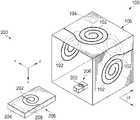
- FIG. 1An example of a preferred embodiment of apparatus for wireless power transmittal according to the invention is shown in FIG. 1 .
- the apparatus 100includes a number of primary coils 102 for transmitting power to a secondary side receiver (not shown in FIG. 1 ).
- a driver circuit 104is coupled to the coils 102 .
- the driver circuit 104is capable of adjustment in terms of frequency and amplitude in order to adjust transmission parameters.
- Suitable startup circuitryis provided in the driver circuit 104 in order to enable the apparatus 100 to achieve appropriate bias levels prior to driving the primary side coils 102 .
- Thispreferably provides the capability for a smooth startup that mitigates or eliminates wasted energy and radiated emissions.
- Adjustable resistorsmay also be provided in order to regulate the amplitude of the transmitted signal for output at the primary side coils 102 .
- the primary side coils 102are preferably arranged so that they do not share the same plane. It has been found that providing primary side coils in non-coplanar configuration tends to provide favorable signal transmission coverage to a space in proximity to the primary side coils.
- the primary coils 102are non-coplanar, arranged around the periphery of a container 106 , in this case box-shaped.
- primary coilse.g., 102
- a containere.g., 106
- a containermay be implemented in various three-dimensional forms as alternatives to the generally rectangular box 106 shown without departure from the principles of the invention.
- containers of tubular, cylindrical, envelope, pouch, bag, or pocket shapemay also be used.
- one or more inductive resonance receivers having secondary coilsmay be placed in close proximity with the apparatus for wireless power transmittal as exemplified in and described with respect to FIG. 1 .
- FIG. 2another preferred embodiment of apparatus of the invention 200 is shown. It has been determined that a suitable secondary side coil 202 may be used to receive signals transmitted by the primary side coil(s) 102 .
- apparatus for wireless power transmittal 100may be used for recharging power storage elements 204 , including but not limited to batteries, capacitors, and super-capacitors.
- receivers 206 having secondary coils 202are included in association with an electronic systems having additional functionality, such as cell phones, toys, 3D glasses, cameras, remote controls, and the like.
- additional functionalitysuch as cell phones, toys, 3D glasses, cameras, remote controls, and the like.
- the receiver 206is placed in proximity with the primary coils 102 of the power transmittal apparatus 100 for recharging with little or no care as to the orientation of the receiver 206 in relation to the primary coils 102 .
- the secondary side receiver 206includes a secondary side coil 202 suitable to be inductively coupled with the primary side coil 102 for receiving the signal output of the primary side apparatus 100 .
- the secondary side receiver 206also includes circuitry 208 suitable for such functions as managing received signals, generating feedback signals such as power levels, load levels, and secondary side frequency, for use in making adjustments to the output of the primary side 100 .
- the configuration of the power transmittal apparatus 100providing non-coplanar coils 102 , as shown on the periphery of the container 106 in this example, permits the transmission of one or more signals from one or more of the primary coils 102 to the secondary coil(s) 202 of the proximal receiver 206 without requiring precise, coplanar, or parallel alignment of the respective coils 102 , 202 .
- the box-like container 106includes primary coils 102 on each of its three axes, X, Y, and Z, at various angles ⁇ , to provide multi-directional transmission of power signals to the secondary coil 202 almost without regard to the precise locations and/or orientations ( ⁇ ) of the receiver(s) 206 .
- signalsmay be transmitted from primary coils to parallel or coplanar secondary coils, such alignment is not required. It is contemplated that apparatus may be implemented in accordance with the invention in configurations which preclude coplanar or parallel primary and secondary coils, for example with cylindrical primary side containers.
- apparatus 300 for wireless power transmittalhas non-coplanar primary coils 302 connected in series. Operating the primary coils 302 in series transmits signals having various orientations for reception by suitable secondary coil(s).
- apparatus 400is shown in which the primary coils 402 are arranged in an interlaced configuration. In this configuration, signals transmitted from the primary coils may be concentrated in specific areas in their proximity. Preferably, transmittals through the primary coils may be controlled by dynamic coil selection.
- the outside of the container 106may be covered with electromagnetic shielding (not shown) to provide a Faraday Cage. This effectively eliminates or attenuates the emission of electromagnetic radiation from the container, and thereby reduces the potential of interference with other electronics or the environment.
- the container including the apparatus of the inventionmay be of a fixed nature, drawing power from a fixed source, or may be portable, in which case an energy storage element may be used to power to apparatus.
- the apparatus of the inventionmay also be implemented in transmitter/receiver combinations, further described herein.
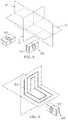
- the apparatus 500 for wireless power transmittalmay be implemented in forms that dispense with the container depicted elsewhere herein.
- the XY, YZ, and XZ planes in the apparatus 500each contain one or more primary coils (not shown).
- devices including suitable secondary coils, e.g. 510may be placed in the proximity of the apparatus 500 in order to receive a signal therefrom.
- the apparatus 500may be embedded within a table lamp, and remote control devices containing secondary coils 510 may be placed near the lamp for recharging.
- Such a systemmay also include an energy storage element, which would be useful for power outages or to move the unit to a location that is not near a power outlet.
- the primary coils 602 in the invented wireless power transmittal apparatus 600may lie entirely in one plane.
- the coil(s), e.g., 602may lie in tow or more planes.
- a signal transmitted from the coil shown 602transmits in more than one direction for receipt by a suitable device 610 in proximity.
- Primary coilsneed not be on orthogonal planes, and may be oriented at various angles ⁇ .
- Preferably primary coil parameterscan be changed based on anticipated and/or real-time operational conditions. For example, inductance values, number of windings, the selection of frequencies, and the propagation of different waveguides, may be changed without departure from the invention.
- Combinations of different planesmay also be used to target specific transmission directions. This yields many possible different coil and plane combinations, which allows for flexibility in adjusting the transmission path/direction, either along the X, Y, and Z axes, or adjusting the angle ⁇ primary coil(s).
- a system 700may be deployed in which wireless power apparatus 702 is implemented as a transceiver. Using multiple transceiver apparatuses 702 , the apparatus 702 may be inductively coupled in various combinations such as daisy chain, star, mesh, or other network configurations. These transceivers 702 may also include energy storage devices such as batteries in order to provide system flexibility, removing the limitation of requiring placement near power outlets. These transceiver units 702 can also be used as power repeaters to extend the distance for power transmission, or to provide a transmission path around obstacles.
- Communication between each of the receivers 702is preferably maintained to improve power transfer and communicate system 700 parametric data such as power received, battery life remaining, charge rate, number of charge cycles, orientation, fault/warning conditions, and other operating parameters.
- the transceiver apparatus 702may also be used in combination with transmit-only 704 , and receive-only 706 units.
- a system 700 as shown in FIG. 7may be used, for example, in the context of a home entertainment setup with charging apparatus 702 , storage boxes 705 , repeaters 704 , and remote powered speaker receivers 706 .
- the wireless power transmittal apparatusmay be equipped with a communication protocol for providing communication functionality between each primary and secondary coil.
- Communication functionsmay include, for example, monitoring the amount of power received by a receiver. This allows the primary side transmitter to vary different parameters to help optimize the power transfer to the receiver. An example is to increase or decrease output power in selected primary coils to determine the best coil or coil combination to use to efficiently transfer the signal. Another example is to mount each primary coil on a movable assembly such as a motorized gimbal, to allow movement of the coil to various orientation angles to optimize power transmission. In a feedback loop, the primary side apparatus may alter the coil angle, and when the receiver reports its power received, this loop may then be repeated to find the most preferred coil position for present-time operating conditions.
- Another example of communication functionsincludes device identification, such as through a serial number.
- receiver status parametricscan also be communicated, such as power received, battery life remaining, charge rate, number of charge cycles, orientation, fault/warning conditions, and other operating parameters.
- Communicationmay be embedded in the power transfer signal transmissions.
- power transferand be turned on/off creating an on/off pulse stream of power that is interpreted into a data stream. Communication and other aspects of the invention are further described in the applications incorporated by reference.
Landscapes
- Engineering & Computer Science (AREA)
- Power Engineering (AREA)
- Computer Networks & Wireless Communication (AREA)
- Charge And Discharge Circuits For Batteries Or The Like (AREA)
Abstract
Description
Claims (20)
Priority Applications (1)
| Application Number | Priority Date | Filing Date | Title |
|---|---|---|---|
| US17/107,184US11309126B2 (en) | 2009-02-23 | 2020-11-30 | Wireless power transmittal |
Applications Claiming Priority (23)
| Application Number | Priority Date | Filing Date | Title |
|---|---|---|---|
| US15470409P | 2009-02-23 | 2009-02-23 | |
| US12/710,307US8461847B2 (en) | 2009-02-23 | 2010-02-22 | Electrical interconnect status monitoring system |
| US38274710P | 2010-09-14 | 2010-09-14 | |
| US201161434622P | 2011-01-20 | 2011-01-20 | |
| US201161468685P | 2011-03-29 | 2011-03-29 | |
| US201161504293P | 2011-07-04 | 2011-07-04 | |
| US201161534401P | 2011-09-14 | 2011-09-14 | |
| US13/232,855US9089029B2 (en) | 2010-09-14 | 2011-09-14 | Driver method |
| US13/355,416US9083391B2 (en) | 2011-01-20 | 2012-01-20 | Wireless power transceiver system |
| US201261616860P | 2012-03-28 | 2012-03-28 | |
| US13/434,807US9530555B2 (en) | 2011-03-29 | 2012-03-29 | Wireless power transmittal |
| US13/540,883US8964418B2 (en) | 2011-07-04 | 2012-07-03 | Ultra-low AC-DC power converter to mitigate energy emission |
| US13/616,726US9553457B2 (en) | 2011-09-14 | 2012-09-14 | Tunable synchronous rectifier |
| US13/852,780US9602167B2 (en) | 2012-03-28 | 2013-03-28 | Remote energy transfer system |
| US13/914,501US8896318B2 (en) | 2009-02-23 | 2013-06-10 | Electrical interconnect status monitoring system |
| US14/553,941US9354268B2 (en) | 2009-02-23 | 2014-11-25 | Electrical interconnect status monitoring system |
| US14/630,415US9559596B2 (en) | 2011-07-04 | 2015-02-24 | Ultra-low power converter |
| US14/798,700US9548796B2 (en) | 2011-01-20 | 2015-07-14 | Wireless power transceiver system |
| US14/805,331US9413237B2 (en) | 2010-09-14 | 2015-07-21 | Driver method |
| US15/165,870US9599660B2 (en) | 2009-02-23 | 2016-05-26 | Electrical interconnect status monitoring system |
| US15/231,232US9559585B2 (en) | 2010-09-14 | 2016-08-08 | Driver method |
| US15/390,615US10854378B2 (en) | 2009-02-23 | 2016-12-26 | Wireless power transmittal |
| US17/107,184US11309126B2 (en) | 2009-02-23 | 2020-11-30 | Wireless power transmittal |
Related Parent Applications (1)
| Application Number | Title | Priority Date | Filing Date |
|---|---|---|---|
| US15/390,615ContinuationUS10854378B2 (en) | 2009-02-23 | 2016-12-26 | Wireless power transmittal |
Publications (2)
| Publication Number | Publication Date |
|---|---|
| US20210110971A1 US20210110971A1 (en) | 2021-04-15 |
| US11309126B2true US11309126B2 (en) | 2022-04-19 |
Family
ID=58638525
Family Applications (2)
| Application Number | Title | Priority Date | Filing Date |
|---|---|---|---|
| US15/390,615Active2032-06-16US10854378B2 (en) | 2009-02-23 | 2016-12-26 | Wireless power transmittal |
| US17/107,184ActiveUS11309126B2 (en) | 2009-02-23 | 2020-11-30 | Wireless power transmittal |
Family Applications Before (1)
| Application Number | Title | Priority Date | Filing Date |
|---|---|---|---|
| US15/390,615Active2032-06-16US10854378B2 (en) | 2009-02-23 | 2016-12-26 | Wireless power transmittal |
Country Status (1)
| Country | Link |
|---|---|
| US (2) | US10854378B2 (en) |
Families Citing this family (14)
| Publication number | Priority date | Publication date | Assignee | Title |
|---|---|---|---|---|
| US9225199B2 (en) | 2011-03-22 | 2015-12-29 | Triune Ip, Llc | Variable power energy harvesting system |
| US10063284B2 (en) | 2014-03-04 | 2018-08-28 | Triune Ip Llc | Isolation for communication and power |
| WO2016116985A1 (en)* | 2015-01-21 | 2016-07-28 | パナソニックIpマネジメント株式会社 | Power reception device, and contactless power transmission device provided with same |
| CN108987079A (en)* | 2018-06-12 | 2018-12-11 | 中国电力科学研究院有限公司 | The multidirectional transmitting three dimensional coils of wireless power transmission and radio energy transmission system |
| CN108682531A (en)* | 2018-06-12 | 2018-10-19 | 中国电力科学研究院有限公司 | The multidirectional reception three dimensional coils of wireless power transmission and radio energy transmission system |
| CN109004768B (en) | 2018-06-26 | 2022-05-31 | 华为技术有限公司 | Wireless charging device and method |
| EP3935712A4 (en) | 2019-03-07 | 2022-12-14 | Hubbell Incorporated | Inductive power transfer |
| JP7272420B2 (en)* | 2019-03-18 | 2023-05-12 | 株式会社村田製作所 | Power receiver for wireless power supply system |
| JP6729920B1 (en)* | 2019-08-08 | 2020-07-29 | 株式会社レーザーシステム | Resonance device, power transmission device, and power transmission method |
| US11545857B2 (en) | 2020-07-24 | 2023-01-03 | Nucurrent, Inc. | Reconfigurable wireless power transmitter for computer peripherals |
| US11476718B2 (en)* | 2020-07-24 | 2022-10-18 | Nucurrent, Inc. | Systems for extending wireless power transmission charge volume utilizing repeater antennas |
| US11404919B2 (en) | 2020-07-24 | 2022-08-02 | Nucurrent, Inc. | Modular wireless power transmitters for powering multiple devices |
| CN112104102B (en)* | 2020-08-21 | 2022-10-11 | 广东希荻微电子股份有限公司 | A wireless charging transmitter and wireless charger |
| US11682930B2 (en) | 2021-10-07 | 2023-06-20 | Nucurrent, Inc. | Repeater compatibility verifier for wireless power transmission system |
Citations (109)
| Publication number | Priority date | Publication date | Assignee | Title |
|---|---|---|---|---|
| US3573751A (en) | 1969-04-22 | 1971-04-06 | Sylvania Electric Prod | Fault isolation system for modularized electronic equipment |
| US5450076A (en) | 1991-01-25 | 1995-09-12 | Siemens Aktiengesellschaft | Method for reducing power loss in devices for contactless data and energy transmission, and apparatus for performing the method |
| US5461318A (en) | 1994-06-08 | 1995-10-24 | Borchert; Marshall B. | Apparatus and method for improving a time domain reflectometer |
| US5479610A (en) | 1993-11-01 | 1995-12-26 | Northrop Grumman Corporation | System interface fault isolator test set |
| US5686813A (en) | 1996-05-30 | 1997-11-11 | Houston Audio Manufacturing Company Limited | Mobile phone battery pack with a power-saving function |
| US6188587B1 (en) | 1998-05-16 | 2001-02-13 | Samsung Electronics Co., Ltd. | Switching mode power supply having reduced switching losses in standby mode |
| US6297635B1 (en) | 1998-11-09 | 2001-10-02 | Siemens Aktiengesellschaft | Switchable gradient coil arrangement |
| US20020140234A1 (en) | 2000-08-23 | 2002-10-03 | Capstone Turbine Corporation | System and method for dual mode control of a turbogenerator/motor |
| US20020190579A1 (en) | 2001-02-20 | 2002-12-19 | International Business Machines Corporation | Method and apparatus for controlling power and power loss |
| US20030178976A1 (en) | 2001-12-18 | 2003-09-25 | Xiaoyu Xi | Ultra-low quiescent current low dropout (LDO) voltage regulator with dynamic bias and bandwidth |
| US20040004483A1 (en) | 2002-07-02 | 2004-01-08 | Hazelton Lawrence Dean | Method and apparatus for control and fault detection of an electric load circuit |
| US20040005898A1 (en) | 2002-06-24 | 2004-01-08 | Ntt Docomo, Inc. | Wireless channel setting method for mobile communication system and mobile communication control apparatus |
| US20040046475A1 (en) | 2000-06-08 | 2004-03-11 | Georg Holzheu | Winding with moulded parts, method and set of moulded parts for electrical machines |
| US20040076022A1 (en) | 2002-10-21 | 2004-04-22 | Jong-Woon Hong | Switching mode power supply for low power operation |
| US20050052178A1 (en)* | 2003-09-05 | 2005-03-10 | Siemens Aktiengeselischaft | Magnet coil system for contactless movement of a magnetic body in a working space |
| US20050151659A1 (en) | 2003-12-11 | 2005-07-14 | Donovan David L. | Transmission/distribution line fault indicator with remote polling and current sensing and reporting capability |
| US6944554B2 (en) | 2003-07-11 | 2005-09-13 | Sungkyunkwan University | Method for detecting fault on transmission lines by using harmonics and state transition diagram |
| US20060063974A1 (en)* | 2004-09-21 | 2006-03-23 | Olympus Corporation | Medical device guidance system |
| US7053601B1 (en) | 2001-10-26 | 2006-05-30 | E.O. Schweitzer Mfg. Co. | Microprocessor controlled fault indicator having high visibility LED fault indication |
| US7064968B2 (en) | 2002-12-18 | 2006-06-20 | Fairchild Korea Semiconductor Ltd. | Control for a switching power supply having automatic burst mode operation |
| US20060265181A1 (en) | 2005-05-06 | 2006-11-23 | Intelleflex Corporation | Battery monitor |
| US20070010295A1 (en) | 2005-07-08 | 2007-01-11 | Firefly Power Technologies, Inc. | Power transmission system, apparatus and method with communication |
| US7215924B2 (en) | 2001-03-16 | 2007-05-08 | Aura Communications Technology, Inc. | Techniques for inductive communication systems |
| US7218120B2 (en) | 2004-03-31 | 2007-05-15 | Mitsuba Corporation | Fault detection circuit for a driver circuit |
| US20070159186A1 (en) | 2006-01-11 | 2007-07-12 | Evan Grund | Transmission line pulse measurement system for measuring the response of a device under test |
| EP1826498A1 (en) | 2006-02-27 | 2007-08-29 | Intea Engineering Tecnologie Elettroniche Applicate S.R.L. | Network of wireless fan coils |
| US20080053441A1 (en) | 2006-09-01 | 2008-03-06 | Nellcor Puritan Bennett Incorporated | Method and system of detecting faults in a breathing assistance device |
| US7426239B2 (en) | 2002-07-03 | 2008-09-16 | Infineon Technologies Ag | Method and transmission apparatus for transmitting a bivalent signal |
| US7425803B2 (en) | 2004-08-31 | 2008-09-16 | Stmicroelectronics, Inc. | Method and circuit for driving a low voltage light emitting diode |
| US20090009180A1 (en) | 2007-07-03 | 2009-01-08 | Thomas & Betts International, Inc. | Directional fault current indicator |
| US20090134712A1 (en) | 2007-11-28 | 2009-05-28 | Nigel Power Llc | Wireless Power Range Increase Using Parasitic Antennas |
| US20090243394A1 (en) | 2008-03-28 | 2009-10-01 | Nigelpower, Llc | Tuning and Gain Control in Electro-Magnetic power systems |
| US20090247199A1 (en) | 2008-03-27 | 2009-10-01 | Noriaki Oodachi | Radio power-fed terminal, system, and method |
| US20090243397A1 (en) | 2008-03-05 | 2009-10-01 | Nigel Power, Llc | Packaging and Details of a Wireless Power device |
| US7650187B2 (en) | 2003-11-18 | 2010-01-19 | DEUTSCHES ZENTRUM FüR LUFT-UND RAUMFAHRT E.V. | Assembly for wireless energy communication to an implanted device |
| US20100052431A1 (en) | 2008-09-02 | 2010-03-04 | Sony Corporation | Non-contact power transmission device |
| US7701739B2 (en) | 2001-12-03 | 2010-04-20 | Igo, Inc. | Portable device having integral voltage connector |
| US20100097894A1 (en) | 2005-08-04 | 2010-04-22 | Osamu Kubota | Detection-signal transmitting apparatus |
| US20100146308A1 (en) | 2008-09-26 | 2010-06-10 | Richard Gioscia | Portable power supply device for mobile computing devices |
| US20100164297A1 (en) | 2008-09-27 | 2010-07-01 | Kurs Andre B | Wireless energy transfer using conducting surfaces to shape fields and reduce loss |
| US20100201201A1 (en)* | 2009-02-10 | 2010-08-12 | Qualcomm Incorporated | Wireless power transfer in public places |
| US20100201311A1 (en)* | 2009-02-10 | 2010-08-12 | Qualcomm Incorporated | Wireless charging with separate process |
| WO2010104569A1 (en) | 2009-03-09 | 2010-09-16 | Neurds Inc. | System and method for wireless power transfer in implantable medical devices |
| US20100244579A1 (en) | 2009-03-26 | 2010-09-30 | Seiko Epson Corporation | Coil unit, and power transmission device and power reception device using the coil unit |
| US7808127B2 (en) | 2008-08-04 | 2010-10-05 | Triune Ip Llc | Multile input channel power control circuit |
| US7827334B2 (en) | 2008-06-26 | 2010-11-02 | Triune Ip Llc | Protocol method apparatus and system for the interconnection of electronic systems |
| US7859911B2 (en) | 2008-07-21 | 2010-12-28 | Triune Ip Llc | Circuit and system for programming a floating gate |
| US20110004278A1 (en) | 2009-07-06 | 2011-01-06 | Boston Scientific Neuromodulation Corporation | External Charger for a Medical Implantable Device Using Field Sensing Coils to Improve Coupling |
| US20110008527A1 (en) | 2009-07-08 | 2011-01-13 | Triune Ip Llc | Solid Medication Tracking |
| US20110031928A1 (en) | 2007-12-21 | 2011-02-10 | Soar Roger J | Soldier system wireless power and data transmission |
| US20110102411A1 (en) | 2009-11-03 | 2011-05-05 | Mstar Semiconductor, Inc. | Low-Power Display Control Method and Associated Display Controller |
| US7982492B2 (en) | 2009-06-13 | 2011-07-19 | Triune Systems, Lp | Adaptive termination |
| US8035255B2 (en)* | 2008-09-27 | 2011-10-11 | Witricity Corporation | Wireless energy transfer using planar capacitively loaded conducting loop resonators |
| US20110285212A1 (en) | 2009-03-17 | 2011-11-24 | Mitsubishi Electric Corporation | Input/output apparatus and remote control apparatus |
| US8067948B2 (en) | 2006-03-27 | 2011-11-29 | Cypress Semiconductor Corporation | Input/output multiplexer bus |
| US8102713B2 (en) | 2008-08-04 | 2012-01-24 | Triune Ip Llc | Non-volatile memory monitor |
| US20120028845A1 (en) | 2009-10-04 | 2012-02-02 | Ross Teggatz | Sensor for Detecting Biological Agents in Fluid |
| US20120025752A1 (en) | 2010-07-28 | 2012-02-02 | Triune Ip Llc | Battery charger |
| US20120032632A1 (en) | 2010-08-06 | 2012-02-09 | Soar Roger J | Inductive transmission of power and data through ceramic armor panels |
| US20120139357A1 (en) | 2010-12-01 | 2012-06-07 | Triune Ip Llc | Coupled Inductor Power Transfer System |
| US20120139477A1 (en) | 2010-12-03 | 2012-06-07 | Motorola, Inc. | Power supply circuit having lowidle power dissipation |
| US20120153732A1 (en) | 2008-09-27 | 2012-06-21 | Kurs Andre B | Wireless energy transfer for computer peripheral applications |
| US20120188673A1 (en) | 2011-01-20 | 2012-07-26 | Triune Ip Llc | Electrical line status monitoring system |
| US20120206947A1 (en) | 2011-02-16 | 2012-08-16 | Carlton Michael Haight | Load Detection for a Low Power Mode in an AC-DC Adapter |
| US20120212981A1 (en) | 2011-02-23 | 2012-08-23 | Cody Lin | Power converter with zero voltage switching and related control method thereof |
| US20120235506A1 (en) | 2011-02-11 | 2012-09-20 | Qualcomm Incorporated | Systems and methods for calibration of a wireless power transmitter |
| US20120235508A1 (en) | 2011-03-16 | 2012-09-20 | Katsuei Ichikawa | Non-contact power transmission system, receiving apparatus and transmitting apparatus |
| US20120242164A1 (en) | 2011-03-24 | 2012-09-27 | Triune Ip Llc | Coupled inductor system having multi-tap coil |
| US20120248893A1 (en) | 2011-03-29 | 2012-10-04 | Triune Ip Llc | Wireless Power Transmittal |
| US8300375B2 (en) | 2008-07-21 | 2012-10-30 | Triune Ip Llc | Monitoring method, circuit, and system |
| US20120274838A1 (en) | 2010-10-15 | 2012-11-01 | Triune Ip Llc | Illumination and image capture |
| US8362651B2 (en)* | 2008-10-01 | 2013-01-29 | Massachusetts Institute Of Technology | Efficient near-field wireless energy transfer using adiabatic system variations |
| US20130062967A1 (en) | 2011-09-14 | 2013-03-14 | Triune Ip Llc | Tunable synchronous rectifier |
| US8408900B2 (en) | 2009-07-08 | 2013-04-02 | Triune Ip Llc | Electrochemical dispensing apparatus and method |
| US8461847B2 (en) | 2009-02-23 | 2013-06-11 | Tribune IP LLC | Electrical interconnect status monitoring system |
| US20130175982A1 (en) | 2011-03-02 | 2013-07-11 | Triune Ip Llc | Rechargeable Energy Storage Apparatus |
| US20130181724A1 (en) | 2012-01-17 | 2013-07-18 | Triune Ip, Llc | Method and system of wireless power transfer foreign object detection |
| US20130193771A1 (en) | 2012-01-30 | 2013-08-01 | Triune Ip, Llc | Method and system of wireless power transfer foreign object detection |
| US8508142B2 (en) | 2009-03-20 | 2013-08-13 | O2Micro Inc. | Portable lighting device and method thereof |
| US20130241465A1 (en) | 2009-04-10 | 2013-09-19 | Triune Ip Llc | Adaptive power control for energy harvesting |
| US20130257172A1 (en) | 2012-03-28 | 2013-10-03 | Ross E. Teggatz | Remote energy transfer system |
| US20130257171A1 (en) | 2012-03-27 | 2013-10-03 | Ross E. Teggatz | Resonant circuit dynamic optimization system and method |
| US8552336B2 (en) | 2008-12-23 | 2013-10-08 | Triune Ip Llc | Micro matrix data marking |
| US8583037B2 (en) | 2010-03-10 | 2013-11-12 | Triune Ip Llc | Inductive data communication |
| US8584961B2 (en) | 2010-03-18 | 2013-11-19 | Triune Ip Llc | Marking verification system |
| US8654113B2 (en) | 2008-09-19 | 2014-02-18 | Mstar Semiconductor, Inc. | Ultra-low-power display control circuit and associated method |
| US8664745B2 (en) | 2010-07-20 | 2014-03-04 | Triune Ip Llc | Integrated inductor |
| US20140062381A1 (en) | 2012-02-21 | 2014-03-06 | Triune Ip Llc | Scalable harvesting system and method |
| US8687385B2 (en) | 2009-11-25 | 2014-04-01 | Triune Ip Llc | Low power converter |
| US8704450B2 (en) | 2010-02-26 | 2014-04-22 | Triune Ip, Llc | Flash LED controller |
| US8768455B2 (en) | 2011-06-13 | 2014-07-01 | Triune Ip Llc | Topical applicator |
| US20140225447A1 (en) | 2013-02-11 | 2014-08-14 | Triune Ip Llc | High-frequency wireless power system |
| US20140329720A1 (en) | 2013-05-01 | 2014-11-06 | Triune Ip Llc | Electronic-based biosensor |
| US8901878B2 (en) | 2007-06-05 | 2014-12-02 | Impulse Dynamics Nv | Transcutaneous charging device |
| US8957549B2 (en) | 2008-09-27 | 2015-02-17 | Witricity Corporation | Tunable wireless energy transfer for in-vehicle applications |
| US8964418B2 (en) | 2011-07-04 | 2015-02-24 | Amer Atrash | Ultra-low AC-DC power converter to mitigate energy emission |
| US20150130287A1 (en) | 2011-05-13 | 2015-05-14 | Dr. Hahn Gmbh & Co. Kg | Method and apparatus for contactless transmission of electrical energy between a wall and a door leaf/window sash fastened to this wall |
| US9083391B2 (en) | 2011-01-20 | 2015-07-14 | Triune Systems, LLC | Wireless power transceiver system |
| US9089029B2 (en) | 2010-09-14 | 2015-07-21 | Triune Systems, LLC | Driver method |
| US20150256227A1 (en) | 2014-03-04 | 2015-09-10 | Triune Ip Llc | Isolation for communication and power |
| US9134741B2 (en) | 2009-06-13 | 2015-09-15 | Triune Ip, Llc | Dynamic biasing for regulator circuits |
| US20150341087A1 (en) | 2011-01-20 | 2015-11-26 | Triune Ip, Llc | Multi-use wireless power and data system |
| WO2015195403A1 (en) | 2014-06-19 | 2015-12-23 | Triune Ip Llc | Galvanically isolated switch system |
| US9225199B2 (en) | 2011-03-22 | 2015-12-29 | Triune Ip, Llc | Variable power energy harvesting system |
| US9225293B2 (en) | 2011-07-10 | 2015-12-29 | Triune Systems, LLC | Pop and click noise reduction |
| US9231400B2 (en) | 2011-07-10 | 2016-01-05 | Triune Systems, LLC | Voltage transient protection circuitry |
| US20160033979A1 (en) | 2014-07-30 | 2016-02-04 | Triune Ip, Llc | Power sharing solid-state relay |
| WO2016019139A1 (en) | 2014-07-30 | 2016-02-04 | Triune Ip, Llc | Multi-use wireless power and data system |
| US9343988B2 (en) | 2011-08-05 | 2016-05-17 | Triune Systems, LLC | Current mode regulator |
- 2016
- 2016-12-26USUS15/390,615patent/US10854378B2/enactiveActive
- 2020
- 2020-11-30USUS17/107,184patent/US11309126B2/enactiveActive
Patent Citations (130)
| Publication number | Priority date | Publication date | Assignee | Title |
|---|---|---|---|---|
| US3573751A (en) | 1969-04-22 | 1971-04-06 | Sylvania Electric Prod | Fault isolation system for modularized electronic equipment |
| US5450076A (en) | 1991-01-25 | 1995-09-12 | Siemens Aktiengesellschaft | Method for reducing power loss in devices for contactless data and energy transmission, and apparatus for performing the method |
| US5479610A (en) | 1993-11-01 | 1995-12-26 | Northrop Grumman Corporation | System interface fault isolator test set |
| US5461318A (en) | 1994-06-08 | 1995-10-24 | Borchert; Marshall B. | Apparatus and method for improving a time domain reflectometer |
| US5686813A (en) | 1996-05-30 | 1997-11-11 | Houston Audio Manufacturing Company Limited | Mobile phone battery pack with a power-saving function |
| US6188587B1 (en) | 1998-05-16 | 2001-02-13 | Samsung Electronics Co., Ltd. | Switching mode power supply having reduced switching losses in standby mode |
| US6297635B1 (en) | 1998-11-09 | 2001-10-02 | Siemens Aktiengesellschaft | Switchable gradient coil arrangement |
| US20040046475A1 (en) | 2000-06-08 | 2004-03-11 | Georg Holzheu | Winding with moulded parts, method and set of moulded parts for electrical machines |
| US20020140234A1 (en) | 2000-08-23 | 2002-10-03 | Capstone Turbine Corporation | System and method for dual mode control of a turbogenerator/motor |
| US20020190579A1 (en) | 2001-02-20 | 2002-12-19 | International Business Machines Corporation | Method and apparatus for controlling power and power loss |
| US7215924B2 (en) | 2001-03-16 | 2007-05-08 | Aura Communications Technology, Inc. | Techniques for inductive communication systems |
| US7053601B1 (en) | 2001-10-26 | 2006-05-30 | E.O. Schweitzer Mfg. Co. | Microprocessor controlled fault indicator having high visibility LED fault indication |
| US7701739B2 (en) | 2001-12-03 | 2010-04-20 | Igo, Inc. | Portable device having integral voltage connector |
| US20030178976A1 (en) | 2001-12-18 | 2003-09-25 | Xiaoyu Xi | Ultra-low quiescent current low dropout (LDO) voltage regulator with dynamic bias and bandwidth |
| US20040005898A1 (en) | 2002-06-24 | 2004-01-08 | Ntt Docomo, Inc. | Wireless channel setting method for mobile communication system and mobile communication control apparatus |
| US20040004483A1 (en) | 2002-07-02 | 2004-01-08 | Hazelton Lawrence Dean | Method and apparatus for control and fault detection of an electric load circuit |
| US7426239B2 (en) | 2002-07-03 | 2008-09-16 | Infineon Technologies Ag | Method and transmission apparatus for transmitting a bivalent signal |
| US20040076022A1 (en) | 2002-10-21 | 2004-04-22 | Jong-Woon Hong | Switching mode power supply for low power operation |
| US7064968B2 (en) | 2002-12-18 | 2006-06-20 | Fairchild Korea Semiconductor Ltd. | Control for a switching power supply having automatic burst mode operation |
| US6944554B2 (en) | 2003-07-11 | 2005-09-13 | Sungkyunkwan University | Method for detecting fault on transmission lines by using harmonics and state transition diagram |
| US20050052178A1 (en)* | 2003-09-05 | 2005-03-10 | Siemens Aktiengeselischaft | Magnet coil system for contactless movement of a magnetic body in a working space |
| US7650187B2 (en) | 2003-11-18 | 2010-01-19 | DEUTSCHES ZENTRUM FüR LUFT-UND RAUMFAHRT E.V. | Assembly for wireless energy communication to an implanted device |
| US20050151659A1 (en) | 2003-12-11 | 2005-07-14 | Donovan David L. | Transmission/distribution line fault indicator with remote polling and current sensing and reporting capability |
| US7218120B2 (en) | 2004-03-31 | 2007-05-15 | Mitsuba Corporation | Fault detection circuit for a driver circuit |
| US20080297069A1 (en) | 2004-08-31 | 2008-12-04 | Stmicroelectronics, Inc. | Method and Circuit for Driving a Low Voltage Light Emitting Diode |
| US7425803B2 (en) | 2004-08-31 | 2008-09-16 | Stmicroelectronics, Inc. | Method and circuit for driving a low voltage light emitting diode |
| US20060063974A1 (en)* | 2004-09-21 | 2006-03-23 | Olympus Corporation | Medical device guidance system |
| US20060265181A1 (en) | 2005-05-06 | 2006-11-23 | Intelleflex Corporation | Battery monitor |
| US20070010295A1 (en) | 2005-07-08 | 2007-01-11 | Firefly Power Technologies, Inc. | Power transmission system, apparatus and method with communication |
| US20100097894A1 (en) | 2005-08-04 | 2010-04-22 | Osamu Kubota | Detection-signal transmitting apparatus |
| US20070159186A1 (en) | 2006-01-11 | 2007-07-12 | Evan Grund | Transmission line pulse measurement system for measuring the response of a device under test |
| EP1826498A1 (en) | 2006-02-27 | 2007-08-29 | Intea Engineering Tecnologie Elettroniche Applicate S.R.L. | Network of wireless fan coils |
| US8067948B2 (en) | 2006-03-27 | 2011-11-29 | Cypress Semiconductor Corporation | Input/output multiplexer bus |
| US20080053441A1 (en) | 2006-09-01 | 2008-03-06 | Nellcor Puritan Bennett Incorporated | Method and system of detecting faults in a breathing assistance device |
| US8901878B2 (en) | 2007-06-05 | 2014-12-02 | Impulse Dynamics Nv | Transcutaneous charging device |
| US20090009180A1 (en) | 2007-07-03 | 2009-01-08 | Thomas & Betts International, Inc. | Directional fault current indicator |
| US7969155B2 (en) | 2007-07-03 | 2011-06-28 | Thomas & Betts International, Inc. | Directional fault current indicator |
| US20090134712A1 (en) | 2007-11-28 | 2009-05-28 | Nigel Power Llc | Wireless Power Range Increase Using Parasitic Antennas |
| US20110031928A1 (en) | 2007-12-21 | 2011-02-10 | Soar Roger J | Soldier system wireless power and data transmission |
| US20090243397A1 (en) | 2008-03-05 | 2009-10-01 | Nigel Power, Llc | Packaging and Details of a Wireless Power device |
| US20090247199A1 (en) | 2008-03-27 | 2009-10-01 | Noriaki Oodachi | Radio power-fed terminal, system, and method |
| US20090243394A1 (en) | 2008-03-28 | 2009-10-01 | Nigelpower, Llc | Tuning and Gain Control in Electro-Magnetic power systems |
| US7827334B2 (en) | 2008-06-26 | 2010-11-02 | Triune Ip Llc | Protocol method apparatus and system for the interconnection of electronic systems |
| US8743522B2 (en) | 2008-07-21 | 2014-06-03 | Triune Ip Llc | Monitoring method, circuit and system |
| US8300375B2 (en) | 2008-07-21 | 2012-10-30 | Triune Ip Llc | Monitoring method, circuit, and system |
| US8102718B2 (en) | 2008-07-21 | 2012-01-24 | Triune Ip Llc | Method for programming a floating gate |
| US8693261B2 (en) | 2008-07-21 | 2014-04-08 | Triune Ip Llc | Method for programming a floating gate |
| US7859911B2 (en) | 2008-07-21 | 2010-12-28 | Triune Ip Llc | Circuit and system for programming a floating gate |
| US8441866B2 (en) | 2008-07-21 | 2013-05-14 | Triune Ip Llc | Method for programming a floating gate |
| US8102713B2 (en) | 2008-08-04 | 2012-01-24 | Triune Ip Llc | Non-volatile memory monitor |
| US7808127B2 (en) | 2008-08-04 | 2010-10-05 | Triune Ip Llc | Multile input channel power control circuit |
| US20100052431A1 (en) | 2008-09-02 | 2010-03-04 | Sony Corporation | Non-contact power transmission device |
| US8654113B2 (en) | 2008-09-19 | 2014-02-18 | Mstar Semiconductor, Inc. | Ultra-low-power display control circuit and associated method |
| US20100146308A1 (en) | 2008-09-26 | 2010-06-10 | Richard Gioscia | Portable power supply device for mobile computing devices |
| US20120153732A1 (en) | 2008-09-27 | 2012-06-21 | Kurs Andre B | Wireless energy transfer for computer peripheral applications |
| US8957549B2 (en) | 2008-09-27 | 2015-02-17 | Witricity Corporation | Tunable wireless energy transfer for in-vehicle applications |
| US8035255B2 (en)* | 2008-09-27 | 2011-10-11 | Witricity Corporation | Wireless energy transfer using planar capacitively loaded conducting loop resonators |
| US20100164297A1 (en) | 2008-09-27 | 2010-07-01 | Kurs Andre B | Wireless energy transfer using conducting surfaces to shape fields and reduce loss |
| US8362651B2 (en)* | 2008-10-01 | 2013-01-29 | Massachusetts Institute Of Technology | Efficient near-field wireless energy transfer using adiabatic system variations |
| US8552336B2 (en) | 2008-12-23 | 2013-10-08 | Triune Ip Llc | Micro matrix data marking |
| US20100201201A1 (en)* | 2009-02-10 | 2010-08-12 | Qualcomm Incorporated | Wireless power transfer in public places |
| US20100201311A1 (en)* | 2009-02-10 | 2010-08-12 | Qualcomm Incorporated | Wireless charging with separate process |
| US8461847B2 (en) | 2009-02-23 | 2013-06-11 | Tribune IP LLC | Electrical interconnect status monitoring system |
| US9354268B2 (en) | 2009-02-23 | 2016-05-31 | Triune Ip, Llc | Electrical interconnect status monitoring system |
| US8896318B2 (en) | 2009-02-23 | 2014-11-25 | Triune Ip Llc | Electrical interconnect status monitoring system |
| WO2010104569A1 (en) | 2009-03-09 | 2010-09-16 | Neurds Inc. | System and method for wireless power transfer in implantable medical devices |
| US20110285212A1 (en) | 2009-03-17 | 2011-11-24 | Mitsubishi Electric Corporation | Input/output apparatus and remote control apparatus |
| US8508142B2 (en) | 2009-03-20 | 2013-08-13 | O2Micro Inc. | Portable lighting device and method thereof |
| US20100244579A1 (en) | 2009-03-26 | 2010-09-30 | Seiko Epson Corporation | Coil unit, and power transmission device and power reception device using the coil unit |
| US20130241465A1 (en) | 2009-04-10 | 2013-09-19 | Triune Ip Llc | Adaptive power control for energy harvesting |
| US9106221B2 (en) | 2009-06-13 | 2015-08-11 | Triune Systems, LLC | Adaptive termination |
| US7982492B2 (en) | 2009-06-13 | 2011-07-19 | Triune Systems, Lp | Adaptive termination |
| US20160004267A1 (en) | 2009-06-13 | 2016-01-07 | Triune Ip, Llc | Dynamic biasing for regulator circuits |
| US8373436B2 (en) | 2009-06-13 | 2013-02-12 | Triune Systems, LLC | Adaptive termination |
| US9134741B2 (en) | 2009-06-13 | 2015-09-15 | Triune Ip, Llc | Dynamic biasing for regulator circuits |
| US20110004278A1 (en) | 2009-07-06 | 2011-01-06 | Boston Scientific Neuromodulation Corporation | External Charger for a Medical Implantable Device Using Field Sensing Coils to Improve Coupling |
| US20110008527A1 (en) | 2009-07-08 | 2011-01-13 | Triune Ip Llc | Solid Medication Tracking |
| US20130224679A1 (en) | 2009-07-08 | 2013-08-29 | Triune Ip Llc | Electrochemical dispensing apparatus and method |
| US8408900B2 (en) | 2009-07-08 | 2013-04-02 | Triune Ip Llc | Electrochemical dispensing apparatus and method |
| US20120028845A1 (en) | 2009-10-04 | 2012-02-02 | Ross Teggatz | Sensor for Detecting Biological Agents in Fluid |
| US20110102411A1 (en) | 2009-11-03 | 2011-05-05 | Mstar Semiconductor, Inc. | Low-Power Display Control Method and Associated Display Controller |
| US9214867B2 (en) | 2009-11-25 | 2015-12-15 | Triune Systems, LLC | Low power converter |
| US8687385B2 (en) | 2009-11-25 | 2014-04-01 | Triune Ip Llc | Low power converter |
| US20160105115A1 (en) | 2009-11-25 | 2016-04-14 | Triune Systems, LLC | Low power converter |
| US8704450B2 (en) | 2010-02-26 | 2014-04-22 | Triune Ip, Llc | Flash LED controller |
| US8583037B2 (en) | 2010-03-10 | 2013-11-12 | Triune Ip Llc | Inductive data communication |
| US8584961B2 (en) | 2010-03-18 | 2013-11-19 | Triune Ip Llc | Marking verification system |
| US8664745B2 (en) | 2010-07-20 | 2014-03-04 | Triune Ip Llc | Integrated inductor |
| US20120025752A1 (en) | 2010-07-28 | 2012-02-02 | Triune Ip Llc | Battery charger |
| US20120032632A1 (en) | 2010-08-06 | 2012-02-09 | Soar Roger J | Inductive transmission of power and data through ceramic armor panels |
| US20150326118A1 (en) | 2010-09-14 | 2015-11-12 | Triune Systems, LLC | Driver method |
| US9089029B2 (en) | 2010-09-14 | 2015-07-21 | Triune Systems, LLC | Driver method |
| US20120274838A1 (en) | 2010-10-15 | 2012-11-01 | Triune Ip Llc | Illumination and image capture |
| US20120139357A1 (en) | 2010-12-01 | 2012-06-07 | Triune Ip Llc | Coupled Inductor Power Transfer System |
| US20120139477A1 (en) | 2010-12-03 | 2012-06-07 | Motorola, Inc. | Power supply circuit having lowidle power dissipation |
| US9083391B2 (en) | 2011-01-20 | 2015-07-14 | Triune Systems, LLC | Wireless power transceiver system |
| US20150341087A1 (en) | 2011-01-20 | 2015-11-26 | Triune Ip, Llc | Multi-use wireless power and data system |
| US20120188673A1 (en) | 2011-01-20 | 2012-07-26 | Triune Ip Llc | Electrical line status monitoring system |
| US20150318899A1 (en) | 2011-01-20 | 2015-11-05 | Triune Systems, LLC | Wireless power transceiver system |
| US20120235506A1 (en) | 2011-02-11 | 2012-09-20 | Qualcomm Incorporated | Systems and methods for calibration of a wireless power transmitter |
| US20120206947A1 (en) | 2011-02-16 | 2012-08-16 | Carlton Michael Haight | Load Detection for a Low Power Mode in an AC-DC Adapter |
| US20120212981A1 (en) | 2011-02-23 | 2012-08-23 | Cody Lin | Power converter with zero voltage switching and related control method thereof |
| US20130175982A1 (en) | 2011-03-02 | 2013-07-11 | Triune Ip Llc | Rechargeable Energy Storage Apparatus |
| US20120235508A1 (en) | 2011-03-16 | 2012-09-20 | Katsuei Ichikawa | Non-contact power transmission system, receiving apparatus and transmitting apparatus |
| US9225199B2 (en) | 2011-03-22 | 2015-12-29 | Triune Ip, Llc | Variable power energy harvesting system |
| US20160134191A1 (en) | 2011-03-22 | 2016-05-12 | Triune Systems, LLC | Variable power energy harvesting system |
| US20120242164A1 (en) | 2011-03-24 | 2012-09-27 | Triune Ip Llc | Coupled inductor system having multi-tap coil |
| US20120248893A1 (en) | 2011-03-29 | 2012-10-04 | Triune Ip Llc | Wireless Power Transmittal |
| US20150130287A1 (en) | 2011-05-13 | 2015-05-14 | Dr. Hahn Gmbh & Co. Kg | Method and apparatus for contactless transmission of electrical energy between a wall and a door leaf/window sash fastened to this wall |
| US8768455B2 (en) | 2011-06-13 | 2014-07-01 | Triune Ip Llc | Topical applicator |
| US8964418B2 (en) | 2011-07-04 | 2015-02-24 | Amer Atrash | Ultra-low AC-DC power converter to mitigate energy emission |
| US20150171758A1 (en) | 2011-07-04 | 2015-06-18 | Triune Systems, LLC | Ultra-low power converter |
| US9225293B2 (en) | 2011-07-10 | 2015-12-29 | Triune Systems, LLC | Pop and click noise reduction |
| US20160134099A1 (en) | 2011-07-10 | 2016-05-12 | Triune Systems, LLC | Voltage transient protection circuitry |
| US9231400B2 (en) | 2011-07-10 | 2016-01-05 | Triune Systems, LLC | Voltage transient protection circuitry |
| US9343988B2 (en) | 2011-08-05 | 2016-05-17 | Triune Systems, LLC | Current mode regulator |
| US20130062967A1 (en) | 2011-09-14 | 2013-03-14 | Triune Ip Llc | Tunable synchronous rectifier |
| US20130181724A1 (en) | 2012-01-17 | 2013-07-18 | Triune Ip, Llc | Method and system of wireless power transfer foreign object detection |
| US20130193771A1 (en) | 2012-01-30 | 2013-08-01 | Triune Ip, Llc | Method and system of wireless power transfer foreign object detection |
| US20140062381A1 (en) | 2012-02-21 | 2014-03-06 | Triune Ip Llc | Scalable harvesting system and method |
| US20130257171A1 (en) | 2012-03-27 | 2013-10-03 | Ross E. Teggatz | Resonant circuit dynamic optimization system and method |
| US20130257172A1 (en) | 2012-03-28 | 2013-10-03 | Ross E. Teggatz | Remote energy transfer system |
| US20140225447A1 (en) | 2013-02-11 | 2014-08-14 | Triune Ip Llc | High-frequency wireless power system |
| US20140329720A1 (en) | 2013-05-01 | 2014-11-06 | Triune Ip Llc | Electronic-based biosensor |
| US20150256227A1 (en) | 2014-03-04 | 2015-09-10 | Triune Ip Llc | Isolation for communication and power |
| US20150372676A1 (en) | 2014-06-19 | 2015-12-24 | Triune Ip Llc | Galvanically isolated switch system |
| WO2015195403A1 (en) | 2014-06-19 | 2015-12-23 | Triune Ip Llc | Galvanically isolated switch system |
| US20160033979A1 (en) | 2014-07-30 | 2016-02-04 | Triune Ip, Llc | Power sharing solid-state relay |
| WO2016019137A2 (en) | 2014-07-30 | 2016-02-04 | Triune Ip, Llc | Power sharing solid-state relay |
| WO2016019139A1 (en) | 2014-07-30 | 2016-02-04 | Triune Ip, Llc | Multi-use wireless power and data system |
Also Published As
| Publication number | Publication date |
|---|---|
| US10854378B2 (en) | 2020-12-01 |
| US20170125161A1 (en) | 2017-05-04 |
| US20210110971A1 (en) | 2021-04-15 |
Similar Documents
| Publication | Publication Date | Title |
|---|---|---|
| US11309126B2 (en) | Wireless power transmittal | |
| US9530555B2 (en) | Wireless power transmittal | |
| RU2534020C1 (en) | Wireless charging system for mobile devices | |
| CN105706334B (en) | Wireless power transmission apparatus, wireless power reception device and loop construction | |
| US20190044394A1 (en) | Magnetic power transmission utilizing phased transmitter coil arrays and phased receiver coil arrays | |
| US8558412B2 (en) | Wireless power transmitter, wireless power receiver, and method for wireless power transfer using them | |
| US10027377B2 (en) | Wireless power supply apparatus | |
| CN102484397B (en) | Wireless power transmission device | |
| KR101197579B1 (en) | Space-adaptive Wireless Power Transmission System and Method using Resonance of Evanescent Waves | |
| CN101490923B (en) | Wireless energy transmission method, device and system | |
| US9979239B2 (en) | Systems and methods for wireless power transferring | |
| KR102227504B1 (en) | Wireless power transfer method and device to trasmit power stably to plural wireless power receiving devices | |
| KR20140008020A (en) | Wireless power transmitter, wireless power relay device and wireless power receiver | |
| CN104488166A (en) | Method and apparatus for 3d orientation-free wireless power transfer | |
| KR20140021095A (en) | Wireless power transmission apparatus of improving user's convenience for mobile device usage | |
| US10224750B2 (en) | Wireless power transmission apparatus | |
| US20120119587A1 (en) | Wireless power transfer device | |
| US20230369895A1 (en) | Systems and methods for wireless power transferring | |
| US8760009B2 (en) | Wireless power source | |
| KR101341510B1 (en) | Magnetic energy beamforming method and apparatus for wireless power transmission | |
| US11705759B2 (en) | Wireless charging transmission apparatus by using three-dimensional (3D) polyhedral magnetic resonance based on multi-antenna switching | |
| US11011938B2 (en) | Magnetic field adjusting three-dimensional flexible resonator for wireless power transmission system | |
| KR102028057B1 (en) | Resonator with improved isolation | |
| US20250112502A1 (en) | Wireless Power Transmitter Increasing Uniformity of Electromagnetic Field Distribution | |
| Niyato et al. | Basics of Wireless Energy Harvesting and Transfer. |
Legal Events
| Date | Code | Title | Description |
|---|---|---|---|
| FEPP | Fee payment procedure | Free format text:ENTITY STATUS SET TO UNDISCOUNTED (ORIGINAL EVENT CODE: BIG.); ENTITY STATUS OF PATENT OWNER: LARGE ENTITY | |
| AS | Assignment | Owner name:TRIUNE SYSTEMS, LLC, TEXAS Free format text:CHANGE OF ADDRESS OF ASSIGNEE;ASSIGNOR:TRIUNE SYSTEMS, LLC;REEL/FRAME:055412/0434 Effective date:20180502 Owner name:TRIUNE SYSTEMS, LLC, TEXAS Free format text:ASSIGNMENT OF ASSIGNORS INTEREST;ASSIGNORS:TEGGATZ, ROSS E.;CHEN, WAYNE;SIGNING DATES FROM 20150127 TO 20150218;REEL/FRAME:055411/0626 | |
| STPP | Information on status: patent application and granting procedure in general | Free format text:DOCKETED NEW CASE - READY FOR EXAMINATION | |
| STPP | Information on status: patent application and granting procedure in general | Free format text:NON FINAL ACTION MAILED | |
| STPP | Information on status: patent application and granting procedure in general | Free format text:RESPONSE TO NON-FINAL OFFICE ACTION ENTERED AND FORWARDED TO EXAMINER | |
| STPP | Information on status: patent application and granting procedure in general | Free format text:NOTICE OF ALLOWANCE MAILED -- APPLICATION RECEIVED IN OFFICE OF PUBLICATIONS | |
| STPP | Information on status: patent application and granting procedure in general | Free format text:PUBLICATIONS -- ISSUE FEE PAYMENT VERIFIED | |
| STCF | Information on status: patent grant | Free format text:PATENTED CASE | |
| AS | Assignment | Owner name:JPMORGAN CHASE BANK, N.A., ILLINOIS Free format text:GRANT OF SECURITY INTEREST IN PATENT RIGHTS;ASSIGNORS:SEMTECH CORPORATION;TRIUNE SYSTEMS, L.L.C.;TRIUNE IP, LLC;REEL/FRAME:062389/0057 Effective date:20230112 |