US11307359B2 - Ingress protected, outdoor rated connector with integrated optical connector plug frame - Google Patents
Ingress protected, outdoor rated connector with integrated optical connector plug frameDownload PDFInfo
- Publication number
- US11307359B2 US11307359B2US16/782,828US202016782828AUS11307359B2US 11307359 B2US11307359 B2US 11307359B2US 202016782828 AUS202016782828 AUS 202016782828AUS 11307359 B2US11307359 B2US 11307359B2
- Authority
- US
- United States
- Prior art keywords
- connector
- outer body
- ferrule assembly
- ferrule
- ingress protected
- Prior art date
- Legal status (The legal status is an assumption and is not a legal conclusion. Google has not performed a legal analysis and makes no representation as to the accuracy of the status listed.)
- Active
Links
Images


Classifications
- G—PHYSICS
- G02—OPTICS
- G02B—OPTICAL ELEMENTS, SYSTEMS OR APPARATUS
- G02B6/00—Light guides; Structural details of arrangements comprising light guides and other optical elements, e.g. couplings
- G02B6/24—Coupling light guides
- G02B6/36—Mechanical coupling means
- G02B6/38—Mechanical coupling means having fibre to fibre mating means
- G02B6/3807—Dismountable connectors, i.e. comprising plugs
- G02B6/3869—Mounting ferrules to connector body, i.e. plugs
- G02B6/3871—Ferrule rotatable with respect to plug body, e.g. for setting rotational position ; Fixation of ferrules after rotation
- G—PHYSICS
- G02—OPTICS
- G02B—OPTICAL ELEMENTS, SYSTEMS OR APPARATUS
- G02B6/00—Light guides; Structural details of arrangements comprising light guides and other optical elements, e.g. couplings
- G02B6/24—Coupling light guides
- G02B6/36—Mechanical coupling means
- G02B6/38—Mechanical coupling means having fibre to fibre mating means
- G02B6/3807—Dismountable connectors, i.e. comprising plugs
- G02B6/381—Dismountable connectors, i.e. comprising plugs of the ferrule type, e.g. fibre ends embedded in ferrules, connecting a pair of fibres
- G—PHYSICS
- G02—OPTICS
- G02B—OPTICAL ELEMENTS, SYSTEMS OR APPARATUS
- G02B6/00—Light guides; Structural details of arrangements comprising light guides and other optical elements, e.g. couplings
- G02B6/24—Coupling light guides
- G02B6/36—Mechanical coupling means
- G02B6/38—Mechanical coupling means having fibre to fibre mating means
- G02B6/3807—Dismountable connectors, i.e. comprising plugs
- G02B6/3833—Details of mounting fibres in ferrules; Assembly methods; Manufacture
- G02B6/3847—Details of mounting fibres in ferrules; Assembly methods; Manufacture with means preventing fibre end damage, e.g. recessed fibre surfaces
- G02B6/3849—Details of mounting fibres in ferrules; Assembly methods; Manufacture with means preventing fibre end damage, e.g. recessed fibre surfaces using mechanical protective elements, e.g. caps, hoods, sealing membranes
- G—PHYSICS
- G02—OPTICS
- G02B—OPTICAL ELEMENTS, SYSTEMS OR APPARATUS
- G02B6/00—Light guides; Structural details of arrangements comprising light guides and other optical elements, e.g. couplings
- G02B6/24—Coupling light guides
- G02B6/36—Mechanical coupling means
- G02B6/38—Mechanical coupling means having fibre to fibre mating means
- G02B6/3807—Dismountable connectors, i.e. comprising plugs
- G02B6/3887—Anchoring optical cables to connector housings, e.g. strain relief features
- G02B6/3888—Protection from over-extension or over-compression
- G—PHYSICS
- G02—OPTICS
- G02B—OPTICAL ELEMENTS, SYSTEMS OR APPARATUS
- G02B6/00—Light guides; Structural details of arrangements comprising light guides and other optical elements, e.g. couplings
- G02B6/24—Coupling light guides
- G02B6/36—Mechanical coupling means
- G02B6/38—Mechanical coupling means having fibre to fibre mating means
- G02B6/3807—Dismountable connectors, i.e. comprising plugs
- G02B6/389—Dismountable connectors, i.e. comprising plugs characterised by the method of fastening connecting plugs and sockets, e.g. screw- or nut-lock, snap-in, bayonet type
- G02B6/3894—Screw-lock type
- G—PHYSICS
- G02—OPTICS
- G02B—OPTICAL ELEMENTS, SYSTEMS OR APPARATUS
- G02B6/00—Light guides; Structural details of arrangements comprising light guides and other optical elements, e.g. couplings
- G02B6/24—Coupling light guides
- G02B6/42—Coupling light guides with opto-electronic elements
- G02B6/4201—Packages, e.g. shape, construction, internal or external details
- G02B6/4219—Mechanical fixtures for holding or positioning the elements relative to each other in the couplings; Alignment methods for the elements, e.g. measuring or observing methods especially used therefor
- G02B6/4228—Passive alignment, i.e. without a detection of the degree of coupling or the position of the elements
- G02B6/423—Passive alignment, i.e. without a detection of the degree of coupling or the position of the elements using guiding surfaces for the alignment
- G—PHYSICS
- G02—OPTICS
- G02B—OPTICAL ELEMENTS, SYSTEMS OR APPARATUS
- G02B6/00—Light guides; Structural details of arrangements comprising light guides and other optical elements, e.g. couplings
- G02B6/24—Coupling light guides
- G02B6/36—Mechanical coupling means
- G02B6/38—Mechanical coupling means having fibre to fibre mating means
- G02B6/3807—Dismountable connectors, i.e. comprising plugs
- G02B6/381—Dismountable connectors, i.e. comprising plugs of the ferrule type, e.g. fibre ends embedded in ferrules, connecting a pair of fibres
- G02B6/3816—Dismountable connectors, i.e. comprising plugs of the ferrule type, e.g. fibre ends embedded in ferrules, connecting a pair of fibres for use under water, high pressure connectors
- G—PHYSICS
- G02—OPTICS
- G02B—OPTICAL ELEMENTS, SYSTEMS OR APPARATUS
- G02B6/00—Light guides; Structural details of arrangements comprising light guides and other optical elements, e.g. couplings
- G02B6/24—Coupling light guides
- G02B6/36—Mechanical coupling means
- G02B6/38—Mechanical coupling means having fibre to fibre mating means
- G02B6/3807—Dismountable connectors, i.e. comprising plugs
- G02B6/3887—Anchoring optical cables to connector housings, e.g. strain relief features
- G02B6/3889—Anchoring optical cables to connector housings, e.g. strain relief features using encapsulation for protection, e.g. adhesive, molding or casting resin
Definitions
- the present disclosurerelates generally to fiber optic connectors and systems, and specifically to optical fiber field terminated outdoor rated connectors ingress protected from moisture and debris.
- connection assembliessuch as typical fiber optic connectors
- Fiber optic network segmentsare particularly vulnerable because fiber optic connections require extremely precise termination and alignment between connected components and cable segments that may be disrupted by the presence of fluid or solid contaminants.
- fiber optic network segments connected using conventional technologyare very susceptible to performance and/or availability degradation over time. Accordingly, telecommunication network providers would benefit from a connection assembly capable of maintaining a sealable and secure connection configured to prevent the ingress of unwanted materials into the connection assembly with a reduced number of parts.
- FIG. 1is a perspective view of an ingress protected connector with a movable outer coupling nut
- FIG. 2is a front perspective view of the FIG. 1 connector
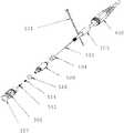
- FIG. 3is an exploded perspective view of the connector of FIG. 1 ;
- FIG. 4is a side view of the assembled connector of FIG. 1 ;
- FIG. 5is a longitudinal section of the connector of FIG. 4 taken in a plane including line A-A′;
- FIG. 5Ais an enlarged fragment of the longitudinal section of FIG. 5 ;
- FIG. 6is a perspective view of a ruggedized connector body with a sealing ring exploded therefrom;
- FIG. 7is a perspective view of a ruggedized connector body with a double ringed ferrule assembly exploded therefrom;
- FIG. 8is an enlarged, perspective view of a double ringed ferrule assembly and insertion point within outer connector body along dotted lines.
- FIG. 9is a side view of the ruggedized connector body depicting cross-section D-D and C-C.
- FIG. 9Ais a cross-section view along line C-C of FIG. 9 .
- FIG. 9Bis a cross-section view along line D-D of FIG. 9 .
- FIG. 10is a perspective view of coupling nut with strain relief.
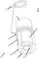
- FIG. 11is a perspective view of ruggedized back body with spring push and environmental seal.
- FIG. 1depicts side view of the ingress protected, ruggedized outdoor connector assembly ( 100 ) according to the present invention.
- a proximal end of front body portion ( 320 ) of ruggedized outdoor connector ( 300 )is secured to a suitable mating element such as an adapter or receptacle interface to make an optical connection between a signal provided by an optical fiber within ferrule ( 510 ) and a corresponding optical fiber within the adapter (not shown).
- a suitable mating elementsuch as an adapter or receptacle interface to make an optical connection between a signal provided by an optical fiber within ferrule ( 510 ) and a corresponding optical fiber within the adapter (not shown).
- a second end or distal end of ruggedized outdoor connector ( 300 )is back portion ( 325 ) over which coupling nut ( 400 ) is accepted.
- Coupling nut ( 400 )has a threaded collar ( 434 ) that secures connector assembly ( 100 ) in adapter.
- Coupling nut main body ( 432 )may be integrated with cable strain relief boot ( 430 ). Strain relief boot ( 430 ) may be removed and cable ( 105 ) can be secured with a crimp ring (not shown). Cable tie wrap ( 101 ) is position beyond cable ( 105 ) on cable ( 105 ). Wrap ( 101 ) helps prevent coupling nut ( 400 ) from sliding down cable ( 105 ) beyond a user defined distance along cable ( 105 ). During install, use would insert proximal end of ruggedized connector ( 300 ) into adapter receptacle, and then move coupling nut ( 400 ) into position and thread with corresponding receiving surface within adapter receptacle. It is important to have the coupling nut ( 400 ) near connector ( 300 ) to facilitate install.
- FIG. 2depicts a front view of FIG. 1 .
- Connector assembly ( 100 )further comprises a plug frame ( 326 ) and ferrule ( 510 ) contained within plug frame ( 326 ).
- Plug frame ( 326 )is integrally molded as part of an inner surface of connector ( 300 ).
- FIG. 3depicts an exploded view of FIG. 1 .
- Connector assembly ( 100 )is environmentally sealed or protected against an ingress of water, debris and other material that might interfere with proper operation of connector assembly ( 100 ) when positioned on a telephone pole, or tower, or on an exposed structure.
- a pair of O-rings or environmental sealsare positioned to protect an inner cavity of ruggedized connector ( 300 ).
- Connector assembly ( 100 )is assembled in direction of arrow “A”.
- Proximal O-ring ( 327 )is positioned in a groove 329 (as shown in FIG. 6 ).
- a distal O-ring ( 526 )provides a seal between ruggedized connector back body ( 500 ) and distal end of ruggedized connector outer body ( 300 ).
- a double flanged (or ringed) ferrule assembly ( 512 )is inserted into ruggedized connector outer body ( 300 ) at a distal end thereof, with a bias spring ( 514 ) under a compressive force provided by a spring push ( 524 ) (refer to FIG. 11 ), when ruggedized back body is secured into distal end of connector outer body ( 300 ).
- Crimp ring ( 104 )is secured to distal end of ruggedized connector back body ( 500 ), and ring ( 104 ) secures cable ( 105 ) via its cable jacket or internal strength members or Kevlar strands between ring ( 104 ) and back post of back body ( 500 ).
- heat shrink tubing ( 103 )is placed over crimp ring ( 104 ) and a portion of cable ( 105 ).
- Coupling nut ( 400 )is free to move proximal or forward along connector outer body ( 300 ) and distal or read along connector outer body until nut ( 400 ) is stopped by cable tie wrap ( 101 ).
- FIG. 4depicts a side view of connector assembly ( 100 ). Front portion ( 320 ) and coupling nut ( 400 ) are assembled forming connector assembly ( 100 ).
- FIG. 5depicts longitudinal section view along line A-A of FIG. 4 .
- Ferrule assembly ( 512 ), with ferrule ( 510 ),is biased forward under force of spring ( 514 ) received in the ruggedized back body ( 500 ).
- the portion of the ferrule assembly ( 512 ) that receives the ferrule ( 510 )may also be referred to as a “body.”
- O-rings ( 327 , 526 )show environmental seal points.
- FIG. 5Ais a zoomed view of proximal or forward end of connector assembly ( 100 ) depicting compression of ferrule bias spring ( 514 ) between back annular ferrule flange (or ring) ( 512 . 1 ) and proximal end of integrated spring push ( 524 ) (refer to FIG. 11 ) at proximal end of ruggedized connector back body ( 500 ).
- Front flange (or ring) ( 512 . 2 )is retained in position by one or more inner alignment keys ( 928 ) (refer to ( FIG. 9A ) formed as part of an inner surface of ruggedized connector outer body ( 300 ).
- FIG. 6depicts a side view of ruggedized connector outer body ( 300 ).
- Front portion ( 320 )comprises a pair of opposing cut-outs or flats ( 322 ), and a directional indicator ( 324 ).
- the flats ( 322 )aid in orienting connector assembly ( 100 ) into an adapter, then coupling nut ( 400 ) is slide forward or proximal to secure connector assembly ( 100 ) with adapter by threading ( 434 ) into a corresponding receiving surface within the adapter.
- coupling nut ( 400 )When coupling nut ( 400 ) is slide forward, it seals against O-ring ( 327 ) to form an environmental sealing surface.
- Integrated plug frame ( 326 )accepts a corresponding fiber optic connector with the adapter to form a communication path.
- FIG. 7depicts an exploded view of ruggedized connector outer body ( 300 ) accepting ferrule assembly ( 512 ) in direction of arrow “I”.
- Ferrule assembly ( 512 )is discussed at FIG. 8 .
- FIG. 8depicts ferrule assembly ( 512 ) with front flange (or ring) ( 512 . 2 ) and back annular flange ( 512 . 1 ), and extended body portion ( 512 . 5 ) called an alignment tube.
- Tube ( 512 . 5 )receives cable ( 105 ) therein and epoxy “E” that when hardened further secures cable ( 105 ).
- Front flange ( 512 . 2 )has a plurality of alignment notches ( 512 .
- Gap ( 512 . 4 )accepts a portion of key ( 928 ) along its longitudinal axis for securing ferrule assembly within the cavity of outer body ( 300 ).
- Spring push ( 524 ) formed integrally with connector back body ( 500 )has an opening that accepts alignment tube therein, and biases spring ( 514 ) forward which pushes ferrule assembly forward.
- Keyse.g., keys 928 . 1 , 928 . 2 , etc.
- Keysare back stopped against back annular flange ( 512 . 1 ).
- FIG. 9depicts ruggedized connector outer body ( 300 ).
- FIG. 9Ais cross-section along line C-C depicting alignment keys ( 928 ) integrally molded as part of connector outer body ( 300 ) inner surface.
- FIG. 9Bis cross-section along line D-D also depicting alignment keys ( 928 ), distal, inner thread ( 329 ) of outer body ( 300 ) and cavity ( 323 ) forming inner surface of outer body ( 300 ).
- FIG. 10depicts coupling nut ( 400 ) with strain relief.
- Proximal thread ( 434 )secures connector assembly ( 100 ) into adapter (not shown).
- Body ( 432 )provides protection for ruggedized connector back body ( 500 ) with spring push ( 524 ), and a strain relief boot ( 430 ), that directs unwanted pull force on cable ( 105 ) away from ferrule assembly ( 512 ).
- FIG. 11depicts ruggedized back body ( 500 ) further comprising a spring push ( 524 ) configured as a cup-shaped member to accept ferrule assembly ( 512 ) with a ferrule ( 510 ) secured to a proximal end thereof.
- Bias spring ( 514 )is depicted compressed under the force of spring push ( 524 ), when back body ( 500 ) is secured to connector front body ( 300 ) via inner threads ( 329 ).
- Strength members ( 552 ) or Kevlaris positioned over crimp ring.
- compositions, methods, and devicesare described in terms of “comprising” various components or steps (interpreted as meaning “including, but not limited to”), the compositions, methods, and devices can also “consist essentially of” or “consist of” the various components and steps, and such terminology should be interpreted as defining essentially closed-member groups. It will be further understood by those within the art that if a specific number of an introduced claim recitation is intended, such an intent will be explicitly recited in the claim, and in the absence of such recitation no such intent is present. For example, as an aid to understanding, the following appended claims may contain usage of the introductory phrases “at least one” and “one or more” to introduce claim recitations.
- a rangeincludes each individual member.
- a group having 1-3 cellsrefers to groups having 1, 2, or 3 cells.
- a group having 1-5 cellsrefers to groups having 1, 2, 3, 4, or 5 cells, and so forth.
Landscapes
- Physics & Mathematics (AREA)
- General Physics & Mathematics (AREA)
- Optics & Photonics (AREA)
- Mechanical Coupling Of Light Guides (AREA)
Abstract
Description
Claims (17)
Priority Applications (2)
| Application Number | Priority Date | Filing Date | Title |
|---|---|---|---|
| US16/782,828US11307359B2 (en) | 2019-02-07 | 2020-02-05 | Ingress protected, outdoor rated connector with integrated optical connector plug frame |
| PCT/US2020/017163WO2020163683A1 (en) | 2019-02-07 | 2020-02-07 | Ingress protected, outdoor rated connector with integrated optical connector plug frame |
Applications Claiming Priority (2)
| Application Number | Priority Date | Filing Date | Title |
|---|---|---|---|
| US201962802635P | 2019-02-07 | 2019-02-07 | |
| US16/782,828US11307359B2 (en) | 2019-02-07 | 2020-02-05 | Ingress protected, outdoor rated connector with integrated optical connector plug frame |
Publications (2)
| Publication Number | Publication Date |
|---|---|
| US20200257060A1 US20200257060A1 (en) | 2020-08-13 |
| US11307359B2true US11307359B2 (en) | 2022-04-19 |
Family
ID=71945102
Family Applications (1)
| Application Number | Title | Priority Date | Filing Date |
|---|---|---|---|
| US16/782,828ActiveUS11307359B2 (en) | 2019-02-07 | 2020-02-05 | Ingress protected, outdoor rated connector with integrated optical connector plug frame |
Country Status (2)
| Country | Link |
|---|---|
| US (1) | US11307359B2 (en) |
| WO (1) | WO2020163683A1 (en) |
Cited By (2)
| Publication number | Priority date | Publication date | Assignee | Title |
|---|---|---|---|---|
| US20210364715A1 (en)* | 2020-05-20 | 2021-11-25 | Commscope Technologies Llc | Active optical cable assemblies |
| US11982845B2 (en) | 2021-02-24 | 2024-05-14 | Senko Advanced Components, Inc. | Ingress-protected optical fiber connector assembly |
Families Citing this family (1)
| Publication number | Priority date | Publication date | Assignee | Title |
|---|---|---|---|---|
| US11307359B2 (en)* | 2019-02-07 | 2022-04-19 | Senko Advanced Components, Inc. | Ingress protected, outdoor rated connector with integrated optical connector plug frame |
Citations (65)
| Publication number | Priority date | Publication date | Assignee | Title |
|---|---|---|---|---|
| US6116790A (en) | 1996-06-28 | 2000-09-12 | The Whitaker Corporation | Optical connector |
| US6409393B1 (en) | 2000-02-18 | 2002-06-25 | Molex Incorporated | Fiber optic connector assembly and method of assembly |
| US6542674B1 (en) | 2000-08-25 | 2003-04-01 | Corning Cable Systems Llc | Fiber optic cables with strength members |
| US6546175B1 (en) | 2000-05-26 | 2003-04-08 | Corning Cable Systems Llc | Self-supporting fiber optic cable |
| US6648520B2 (en) | 2001-09-28 | 2003-11-18 | Corning Cable Systems Llc | Fiber optic plug |
| US6908233B2 (en) | 2002-09-06 | 2005-06-21 | Seiko Instruments Inc. | Optical connector plug, optical connector adapter and optical connector |
| US20060018604A1 (en)* | 2004-07-26 | 2006-01-26 | Baudouin Bareel | Optical fiber connector |
| US20060045428A1 (en) | 2004-08-24 | 2006-03-02 | Thomas Theuerkorn | Fiber optic receptacle and plug assemblies |
| US7090407B2 (en) | 2000-05-26 | 2006-08-15 | Corning Cable Systems Llc | Preconnectorized fiber optic drop cables and assemblies for efficient deployment |
| US7090406B2 (en) | 2000-05-26 | 2006-08-15 | Corning Cable Systems Llc | Preconnectorized fiber optic drop cables and assemblies |
| US7111990B2 (en) | 2000-05-26 | 2006-09-26 | Corning Cable Systems, Llc | Figure-eight preconnectorized fiber optic drop cables and assemblies |
| US7113679B2 (en) | 2000-05-26 | 2006-09-26 | Corning Cable Systems, Llc | Fiber optic drop cables and preconnectorized assemblies having toning portions |
| US7121734B2 (en) | 2001-10-12 | 2006-10-17 | Seikoh Giken Co., Ltd. | Ferrule |
| US7234875B2 (en) | 2005-11-02 | 2007-06-26 | Stratos International, Inc. | Rugged MT-MT connector |
| US7241056B1 (en) | 2006-06-13 | 2007-07-10 | Panduit Corp. | Reversible fiber optic connector |
| US7264402B2 (en) | 2005-03-10 | 2007-09-04 | Corning Cable Systems Llc | Multi-fiber optic receptacle and plug assembly |
| US7281856B2 (en) | 2005-08-15 | 2007-10-16 | Molex Incorporated | Industrial optical fiber connector assembly |
| US7429136B2 (en) | 2006-10-11 | 2008-09-30 | Corning Cable Systems Llc | Connector assembly having multi-fiber ferrule with force centering |
| US20080273855A1 (en) | 2007-05-03 | 2008-11-06 | Furukawa Electric North America, Inc. | Hardened Connector System Including A Translator |
| US7467896B2 (en) | 2000-05-26 | 2008-12-23 | Corning Cable Systems Llc | Fiber optic drop cables and preconnectorized assemblies |
| US7476035B2 (en) | 2007-04-12 | 2009-01-13 | Fiber Systems International | Fiber optic connector having hermaphroditic coupling mechanism |
| US7539380B1 (en) | 2007-11-26 | 2009-05-26 | Corning Cable Systems Llc | Fiber optic cables and assemblies for fiber toward the subscriber applications |
| US7559700B2 (en) | 2006-12-20 | 2009-07-14 | Honda Tsushin Kogyo Co., Ltd. | Shading member-equipped optical connector plug |
| US7567741B2 (en) | 2007-11-26 | 2009-07-28 | Corning Cable Systems Llc | Fiber optic cables and assemblies for fiber toward the subscriber applications |
| US7572065B2 (en) | 2007-01-24 | 2009-08-11 | Adc Telecommunications, Inc. | Hardened fiber optic connector |
| US20090257717A1 (en) | 2008-04-11 | 2009-10-15 | Xin Liu | Fiber optic connector assembly and method for venting gas inside a fiber optic connector sub-assembly |
| WO2010039830A2 (en) | 2008-09-30 | 2010-04-08 | Corning Cable Systems Llc | Fiber optic cable assemblies and securing methods |
| US7744288B2 (en) | 2007-12-11 | 2010-06-29 | Adc Telecommunications, Inc. | Hardened fiber optic connector compatible with hardened and non-hardened fiber optic adapters |
| US7785019B2 (en) | 2005-03-10 | 2010-08-31 | Corning Cable Systems Llc | Multi-fiber fiber optic receptacle and plug assembly |
| US20100329267A1 (en) | 2009-06-25 | 2010-12-30 | Canon Kabushiki Kaisha | Data processing apparatus, data processing method, and computer-readable storage medium |
| US20110222826A1 (en) | 2010-03-11 | 2011-09-15 | Blackburn James D | Strain-releif member and fiber optic drop cable assembly using same |
| US8297850B2 (en) | 2004-08-20 | 2012-10-30 | Sumitomo Electric Industries, Ltd. | Optical connector, and method of assembling optical connector |
| US20130136398A1 (en) | 2010-07-30 | 2013-05-30 | Micah Colen Isenhour | Ferrules with complimentary mating geometry and related fiber optic connectors |
| US8573859B2 (en) | 2008-06-06 | 2013-11-05 | 3M Innovative Properties Company | Field terminable optical fiber connector with splice element |
| US8672560B2 (en) | 2010-08-06 | 2014-03-18 | Tyco Electronics Corporation | Hermaphroditic optical fiber ferrule |
| US8699467B2 (en) | 2008-03-25 | 2014-04-15 | Telefonaktiebolaget Lm Ericsson (Publ) | Anchor carrier selection in multi-carrier wireless network |
| US8814441B2 (en) | 2007-04-20 | 2014-08-26 | Huber+Suhner Ag | Optical connector |
| US8939654B2 (en) | 2012-09-27 | 2015-01-27 | Adc Telecommunications, Inc. | Ruggedized multi-fiber fiber optic connector with sealed dust cap |
| US9239441B2 (en) | 2000-05-26 | 2016-01-19 | Corning Cable Systems Llc | Fiber optic drop cables and preconnectorized assemblies having toning portions |
| US9304262B2 (en) | 2011-11-23 | 2016-04-05 | Commscope Technologies Llc | Multi-fiber optic connector |
| US9310570B2 (en) | 2011-02-17 | 2016-04-12 | Commscope Technologies Llc | Fiber-optic connection arrangement and adapter sleeve |
| WO2016073273A2 (en) | 2014-11-04 | 2016-05-12 | 3M Innovative Properties Company | Field installed optical fiber connector for jacketed fiber cable and termination method |
| US9397441B2 (en) | 2013-03-15 | 2016-07-19 | Cinch Connections, Inc. | Connector with anti-decoupling mechanism |
| US20160209599A1 (en)* | 2013-08-24 | 2016-07-21 | Tyco Electronicss Raychem Bvba | Ruggedized fiber optic connectors and connection systems |
| US9519114B2 (en) | 2014-07-03 | 2016-12-13 | Commscope Technologies Llc | Optical fiber connector for multi-fiber cable |
| US9535230B2 (en) | 2014-01-31 | 2017-01-03 | Senko Advanced Components, Inc. | Integrated fiber optic cable fan-out connector |
| US9684138B2 (en) | 2012-05-22 | 2017-06-20 | Commscope Technologies Llc | Ruggedized fiber optic connector |
| US20170227719A1 (en) | 2014-07-03 | 2017-08-10 | Commscope Technologies Llc | Optical fiber connector for multi-fiber cable |
| US9854151B2 (en) | 2013-09-27 | 2017-12-26 | Fujifilm Corporation | Imaging device and focusing control method |
| US20180081127A1 (en) | 2015-04-03 | 2018-03-22 | CommScope Connectivity Belgium BVBA | Low cost hardened fiber optic connection system |
| US20180224610A1 (en) | 2013-07-16 | 2018-08-09 | 3M Innovative Properties Company | Connector for telecommunication enclosures |
| WO2018157115A1 (en) | 2017-02-27 | 2018-08-30 | Commscope, Inc. Of North Carolina | Hardened converter and sealing shell for field terminated connector |
| US20180329157A1 (en) | 2017-05-11 | 2018-11-15 | Ppc Broadband, Inc. | Pushable Optical Connector With Connector-Integrated Articulation |
| US20180335580A1 (en) | 2017-05-18 | 2018-11-22 | Corning Research & Development Corporation | Fiber optic connector with polymeric material between fiber end and ferrule end, and fabrication method |
| US10162126B2 (en) | 2014-12-01 | 2018-12-25 | Commscope Asia Holdings B.V. | Multi-fiber optic connector with pivotally-aligned ferrule and resilient alignment pins |
| US10162215B2 (en) | 2017-04-19 | 2018-12-25 | Chung Yuan Christian University | Automatic backlight control system and method thereof |
| US10180541B2 (en) | 2014-12-19 | 2019-01-15 | CommScope Connectivity Belgium BVBA | Hardened fiber optic connector with pre-compressed spring |
| US10197739B2 (en) | 2015-02-23 | 2019-02-05 | Sei Optifrontier Co., Ltd. | Optical connector plug, receptacle for optical connector, and optical connector connection structure |
| US10234641B2 (en) | 2016-06-14 | 2019-03-19 | Clearfield, Inc. | In-line sealed adapter tube |
| US20190107667A1 (en) | 2013-10-25 | 2019-04-11 | Radiant Opto-Electronics Corporation | Light assembly, backlight module and liquid crystal display |
| US10401578B2 (en) | 2014-06-23 | 2019-09-03 | CommScope Connectivity Belgium BVBA | Fiber optic connector with partial threaded portion and method of using the same |
| WO2019173350A1 (en) | 2018-03-06 | 2019-09-12 | Commscope Technologies Llc | Modular hardened optical fiber connector and assembly method thereof |
| US10502907B2 (en) | 2016-03-14 | 2019-12-10 | Commscope Technologies Llc | Ruggedized female fiber optic connector cable assembly |
| US10613278B2 (en) | 2010-01-29 | 2020-04-07 | CommScope Connectivity Belgium BVBA | Cable sealing device, cable termination and attaching device |
| US20200257060A1 (en)* | 2019-02-07 | 2020-08-13 | Senko Adcanced Components, Inc | Ingress protected, outdoor rated connector with integrated optical connector plug frame |
Family Cites Families (1)
| Publication number | Priority date | Publication date | Assignee | Title |
|---|---|---|---|---|
| CN105283787B (en)* | 2013-06-13 | 2018-05-25 | 美国北卡罗来纳康普公司 | For the connector of multi-core optical fiber |
- 2020
- 2020-02-05USUS16/782,828patent/US11307359B2/enactiveActive
- 2020-02-07WOPCT/US2020/017163patent/WO2020163683A1/ennot_activeCeased
Patent Citations (124)
| Publication number | Priority date | Publication date | Assignee | Title |
|---|---|---|---|---|
| US6585423B1 (en) | 1996-06-28 | 2003-07-01 | The Whitaker Corporation | Connector system having interlocking inner housing |
| US7001079B2 (en) | 1996-06-28 | 2006-02-21 | The Whitaker Corporation | Optical connector |
| US6116790A (en) | 1996-06-28 | 2000-09-12 | The Whitaker Corporation | Optical connector |
| US6409393B1 (en) | 2000-02-18 | 2002-06-25 | Molex Incorporated | Fiber optic connector assembly and method of assembly |
| US7111990B2 (en) | 2000-05-26 | 2006-09-26 | Corning Cable Systems, Llc | Figure-eight preconnectorized fiber optic drop cables and assemblies |
| US7113679B2 (en) | 2000-05-26 | 2006-09-26 | Corning Cable Systems, Llc | Fiber optic drop cables and preconnectorized assemblies having toning portions |
| US7785015B2 (en) | 2000-05-26 | 2010-08-31 | Corning Cable Systems Llc | Fiber optic drop cables and preconnectorized assemblies |
| US6785450B2 (en) | 2000-05-26 | 2004-08-31 | Corning Cable Systems Llc | Self-supporting fiber optic cable |
| US7467896B2 (en) | 2000-05-26 | 2008-12-23 | Corning Cable Systems Llc | Fiber optic drop cables and preconnectorized assemblies |
| US6546175B1 (en) | 2000-05-26 | 2003-04-08 | Corning Cable Systems Llc | Self-supporting fiber optic cable |
| US9239441B2 (en) | 2000-05-26 | 2016-01-19 | Corning Cable Systems Llc | Fiber optic drop cables and preconnectorized assemblies having toning portions |
| US10114176B2 (en) | 2000-05-26 | 2018-10-30 | Corning Optical Communications LLC | Fiber optic drop cables and preconnectorized assemblies |
| US7918609B2 (en) | 2000-05-26 | 2011-04-05 | Corning Cable Systems Llc | Fiber optic drop cables and preconnectorized assemblies |
| US7090407B2 (en) | 2000-05-26 | 2006-08-15 | Corning Cable Systems Llc | Preconnectorized fiber optic drop cables and assemblies for efficient deployment |
| US7090406B2 (en) | 2000-05-26 | 2006-08-15 | Corning Cable Systems Llc | Preconnectorized fiber optic drop cables and assemblies |
| US7881576B2 (en) | 2000-05-26 | 2011-02-01 | Corning Cable Systems Llc | Fiber optic drop cables and preconnectorized assemblies |
| US6542674B1 (en) | 2000-08-25 | 2003-04-01 | Corning Cable Systems Llc | Fiber optic cables with strength members |
| US6714710B2 (en) | 2000-08-25 | 2004-03-30 | Corning Cable Systems, Llc | Fiber optic cables with strength members |
| US6648520B2 (en) | 2001-09-28 | 2003-11-18 | Corning Cable Systems Llc | Fiber optic plug |
| US6899467B2 (en) | 2001-09-28 | 2005-05-31 | Corning Cable Systems Llc | Fiber optic plug and receptacle assembly |
| US7121734B2 (en) | 2001-10-12 | 2006-10-17 | Seikoh Giken Co., Ltd. | Ferrule |
| US7118283B2 (en) | 2002-09-06 | 2006-10-10 | Seikoh Giken Co., Ltd. | Optical connector plug, optical connector adapter and optical connector |
| US6908233B2 (en) | 2002-09-06 | 2005-06-21 | Seiko Instruments Inc. | Optical connector plug, optical connector adapter and optical connector |
| US7226215B2 (en) | 2004-07-26 | 2007-06-05 | Nexans | Optical fiber connector |
| US20060018604A1 (en)* | 2004-07-26 | 2006-01-26 | Baudouin Bareel | Optical fiber connector |
| US8297850B2 (en) | 2004-08-20 | 2012-10-30 | Sumitomo Electric Industries, Ltd. | Optical connector, and method of assembling optical connector |
| US20060045428A1 (en) | 2004-08-24 | 2006-03-02 | Thomas Theuerkorn | Fiber optic receptacle and plug assemblies |
| US7264402B2 (en) | 2005-03-10 | 2007-09-04 | Corning Cable Systems Llc | Multi-fiber optic receptacle and plug assembly |
| US7654747B2 (en) | 2005-03-10 | 2010-02-02 | Corning Cable Systems Llc | Multi-fiber fiber optic receptacle and plug assembly |
| US7785019B2 (en) | 2005-03-10 | 2010-08-31 | Corning Cable Systems Llc | Multi-fiber fiber optic receptacle and plug assembly |
| US8506173B2 (en) | 2005-03-10 | 2013-08-13 | Corning Cable Systems Llc | Multi-fiber fiber optic receptacle and plug assembly |
| US7281856B2 (en) | 2005-08-15 | 2007-10-16 | Molex Incorporated | Industrial optical fiber connector assembly |
| US7234875B2 (en) | 2005-11-02 | 2007-06-26 | Stratos International, Inc. | Rugged MT-MT connector |
| US7344317B2 (en) | 2005-11-02 | 2008-03-18 | Stratos International, Inc. | Rugged MT-MT connector |
| US8496384B2 (en) | 2006-06-13 | 2013-07-30 | Panduit Corp. | Reversible fiber optic connector |
| US7654748B2 (en) | 2006-06-13 | 2010-02-02 | Panduit Corp. | Reversible fiber optic connector |
| US8348519B2 (en) | 2006-06-13 | 2013-01-08 | Panduit Corp. | Reversible fiber optic connector |
| US8231282B2 (en) | 2006-06-13 | 2012-07-31 | Panduit Corp. | Reversible fiber optic connector |
| US8052333B2 (en) | 2006-06-13 | 2011-11-08 | Panduit Corp. | Reversible fiber optic connector |
| US8714835B2 (en) | 2006-06-13 | 2014-05-06 | Panduit Corp. | Reversible fiber optic connector |
| US7891882B2 (en) | 2006-06-13 | 2011-02-22 | Panduit Corp. | Reversible fiber optic connector |
| US7241056B1 (en) | 2006-06-13 | 2007-07-10 | Panduit Corp. | Reversible fiber optic connector |
| US7429136B2 (en) | 2006-10-11 | 2008-09-30 | Corning Cable Systems Llc | Connector assembly having multi-fiber ferrule with force centering |
| US7559700B2 (en) | 2006-12-20 | 2009-07-14 | Honda Tsushin Kogyo Co., Ltd. | Shading member-equipped optical connector plug |
| US20190324217A1 (en) | 2007-01-24 | 2019-10-24 | Commscope Technologies Llc | Hardened fiber optic connector |
| US8770862B2 (en) | 2007-01-24 | 2014-07-08 | Adc Telecommunications, Inc. | Hardened fiber optic connector |
| US7572065B2 (en) | 2007-01-24 | 2009-08-11 | Adc Telecommunications, Inc. | Hardened fiber optic connector |
| US10338323B2 (en) | 2007-01-24 | 2019-07-02 | Commscope Technologies Llc | Hardened fiber optic connector |
| US9664862B2 (en) | 2007-01-24 | 2017-05-30 | Commscope Technologies Llc | Hardened fiber optic connector |
| US7476035B2 (en) | 2007-04-12 | 2009-01-13 | Fiber Systems International | Fiber optic connector having hermaphroditic coupling mechanism |
| US8814441B2 (en) | 2007-04-20 | 2014-08-26 | Huber+Suhner Ag | Optical connector |
| US20080273855A1 (en) | 2007-05-03 | 2008-11-06 | Furukawa Electric North America, Inc. | Hardened Connector System Including A Translator |
| US7539380B1 (en) | 2007-11-26 | 2009-05-26 | Corning Cable Systems Llc | Fiber optic cables and assemblies for fiber toward the subscriber applications |
| US7796853B2 (en) | 2007-11-26 | 2010-09-14 | Corning Cable Systems Llc | Fiber optic cables and assemblies for fiber toward the subscriber applications |
| US7567741B2 (en) | 2007-11-26 | 2009-07-28 | Corning Cable Systems Llc | Fiber optic cables and assemblies for fiber toward the subscriber applications |
| US10101538B2 (en) | 2007-12-11 | 2018-10-16 | Commscope Technologies Llc | Hardened fiber optic connector compatible with hardened and non-hardened fiber optic adapters |
| US8414196B2 (en) | 2007-12-11 | 2013-04-09 | Adc Telecommunications, Inc. | Optical fiber connection system with locking member |
| US20190235177A1 (en) | 2007-12-11 | 2019-08-01 | Commscope Technologies Llc | Hardened fiber optic connector compatible with hardened and non-hardened fiber optic adapters |
| US8202008B2 (en) | 2007-12-11 | 2012-06-19 | Adc Telecommunications, Inc. | Hardened fiber optic connection system with multiple configurations |
| US7744288B2 (en) | 2007-12-11 | 2010-06-29 | Adc Telecommunications, Inc. | Hardened fiber optic connector compatible with hardened and non-hardened fiber optic adapters |
| US9482829B2 (en) | 2007-12-11 | 2016-11-01 | Commscope Technologies Llc | Hardened fiber optic connector compatible with hardened and non-hardened fiber optic adapters |
| US7959361B2 (en) | 2007-12-11 | 2011-06-14 | Adc Telecommunications, Inc. | Hardened fiber optic connection system |
| US7942590B2 (en) | 2007-12-11 | 2011-05-17 | Adc Telecommunications, Inc. | Hardened fiber optic connector and cable assembly with multiple configurations |
| US7744286B2 (en) | 2007-12-11 | 2010-06-29 | Adc Telecommunications, Inc. | Hardened fiber optic connection system with multiple configurations |
| US7762726B2 (en) | 2007-12-11 | 2010-07-27 | Adc Telecommunications, Inc. | Hardened fiber optic connection system |
| US8699467B2 (en) | 2008-03-25 | 2014-04-15 | Telefonaktiebolaget Lm Ericsson (Publ) | Anchor carrier selection in multi-carrier wireless network |
| US20090257717A1 (en) | 2008-04-11 | 2009-10-15 | Xin Liu | Fiber optic connector assembly and method for venting gas inside a fiber optic connector sub-assembly |
| US9103995B2 (en) | 2008-06-06 | 2015-08-11 | 3M Innovative Properties Company | Field terminable optical fiber connector with splice element |
| US8840320B2 (en) | 2008-06-06 | 2014-09-23 | 3M Innovative Properties Company | Field terminable optical fiber connector with splice element |
| US8573859B2 (en) | 2008-06-06 | 2013-11-05 | 3M Innovative Properties Company | Field terminable optical fiber connector with splice element |
| WO2010039830A3 (en) | 2008-09-30 | 2010-06-10 | Corning Cable Systems Llc | Fiber optic cable assemblies and securing methods |
| WO2010039830A2 (en) | 2008-09-30 | 2010-04-08 | Corning Cable Systems Llc | Fiber optic cable assemblies and securing methods |
| US20100329267A1 (en) | 2009-06-25 | 2010-12-30 | Canon Kabushiki Kaisha | Data processing apparatus, data processing method, and computer-readable storage medium |
| US20200241218A1 (en) | 2010-01-29 | 2020-07-30 | CommScope Connectivity Belgium BVBA | Cable sealing device, cable termination and attaching device |
| US10613278B2 (en) | 2010-01-29 | 2020-04-07 | CommScope Connectivity Belgium BVBA | Cable sealing device, cable termination and attaching device |
| US20110222826A1 (en) | 2010-03-11 | 2011-09-15 | Blackburn James D | Strain-releif member and fiber optic drop cable assembly using same |
| US20130136398A1 (en) | 2010-07-30 | 2013-05-30 | Micah Colen Isenhour | Ferrules with complimentary mating geometry and related fiber optic connectors |
| US8672560B2 (en) | 2010-08-06 | 2014-03-18 | Tyco Electronics Corporation | Hermaphroditic optical fiber ferrule |
| US9310570B2 (en) | 2011-02-17 | 2016-04-12 | Commscope Technologies Llc | Fiber-optic connection arrangement and adapter sleeve |
| US9739951B2 (en) | 2011-02-17 | 2017-08-22 | Commscope Technologies Llc | Fiber-optic connection arrangement and adapter sleeve |
| US9442257B2 (en) | 2011-11-23 | 2016-09-13 | Commscope Technologies Llc | Multi-fiber fiber optic connector |
| US9304262B2 (en) | 2011-11-23 | 2016-04-05 | Commscope Technologies Llc | Multi-fiber optic connector |
| US20180231720A1 (en) | 2011-11-23 | 2018-08-16 | Commscope Technologies Llc | Multi-fiber fiber optic connector |
| US9964715B2 (en) | 2011-11-23 | 2018-05-08 | Commscope Technologies Llc | Multi-fiber fiber optic connector |
| US9684138B2 (en) | 2012-05-22 | 2017-06-20 | Commscope Technologies Llc | Ruggedized fiber optic connector |
| US9291780B2 (en) | 2012-09-27 | 2016-03-22 | Commscope Technologies Llc | Ruggedized multi-fiber fiber optic connector with sealed dust cap |
| US8939654B2 (en) | 2012-09-27 | 2015-01-27 | Adc Telecommunications, Inc. | Ruggedized multi-fiber fiber optic connector with sealed dust cap |
| US9397441B2 (en) | 2013-03-15 | 2016-07-19 | Cinch Connections, Inc. | Connector with anti-decoupling mechanism |
| US20180224610A1 (en) | 2013-07-16 | 2018-08-09 | 3M Innovative Properties Company | Connector for telecommunication enclosures |
| US10317628B2 (en) | 2013-08-24 | 2019-06-11 | CommScope Connectivity Belgium BVBA | Ruggedized fiber optic connectors and connection systems |
| US9733436B2 (en) | 2013-08-24 | 2017-08-15 | CommScope Connectivity Belgium BVBA | Ruggedized fiber optic connectors and connection systems |
| US20190369336A1 (en) | 2013-08-24 | 2019-12-05 | CommScope Connectivity Belgium BVBA | Ruggedized fiber optic connectors and connection systems |
| US20160209599A1 (en)* | 2013-08-24 | 2016-07-21 | Tyco Electronicss Raychem Bvba | Ruggedized fiber optic connectors and connection systems |
| US9854151B2 (en) | 2013-09-27 | 2017-12-26 | Fujifilm Corporation | Imaging device and focusing control method |
| US20190107667A1 (en) | 2013-10-25 | 2019-04-11 | Radiant Opto-Electronics Corporation | Light assembly, backlight module and liquid crystal display |
| US10473866B2 (en) | 2014-01-31 | 2019-11-12 | Senko Advanced Components, Inc. | Integrated fiber optic cable fan-out connector |
| US10012802B2 (en) | 2014-01-31 | 2018-07-03 | Senko Advanced Components, Inc | Integrated fiber optic cable fan-out connector |
| US9535230B2 (en) | 2014-01-31 | 2017-01-03 | Senko Advanced Components, Inc. | Integrated fiber optic cable fan-out connector |
| US20190302389A1 (en) | 2014-01-31 | 2019-10-03 | Senko Advanced Components, Inc. | Integrated fiber optic cable fan-out connector |
| US10401578B2 (en) | 2014-06-23 | 2019-09-03 | CommScope Connectivity Belgium BVBA | Fiber optic connector with partial threaded portion and method of using the same |
| US20200003965A1 (en) | 2014-06-23 | 2020-01-02 | CommScope Connectivity Belgium BVBA | Fiber optic connector with partial threaded portion and method of using the same |
| US10146015B2 (en) | 2014-07-03 | 2018-12-04 | Commscope Technologies Llc | Optical fiber connector for multi-fiber cable |
| US20190179088A1 (en) | 2014-07-03 | 2019-06-13 | Commscope Technologies Llc | Optical fiber connector for multi-fiber cable |
| US9519114B2 (en) | 2014-07-03 | 2016-12-13 | Commscope Technologies Llc | Optical fiber connector for multi-fiber cable |
| US20170227719A1 (en) | 2014-07-03 | 2017-08-10 | Commscope Technologies Llc | Optical fiber connector for multi-fiber cable |
| WO2016073273A3 (en) | 2014-11-04 | 2016-06-30 | 3M Innovative Properties Company | Field installed optical fiber connector for jacketed fiber cable |
| WO2016073273A2 (en) | 2014-11-04 | 2016-05-12 | 3M Innovative Properties Company | Field installed optical fiber connector for jacketed fiber cable and termination method |
| US9983366B2 (en) | 2014-11-04 | 2018-05-29 | 3M Innovative Properties Company | Field installed optical fiber connector for jacketed fiber cable and termination method |
| US20190146161A1 (en) | 2014-12-01 | 2019-05-16 | Commscope Asia Holdings B.V. | Multi-fiber optic connector with pivotally-aligned ferrule |
| US10162126B2 (en) | 2014-12-01 | 2018-12-25 | Commscope Asia Holdings B.V. | Multi-fiber optic connector with pivotally-aligned ferrule and resilient alignment pins |
| US20200012051A1 (en) | 2014-12-19 | 2020-01-09 | Adc Telecommunications (Shanghai) Distribution Co., Ltd. | Hardened fiber optic connector with pre-compressed spring |
| US10180541B2 (en) | 2014-12-19 | 2019-01-15 | CommScope Connectivity Belgium BVBA | Hardened fiber optic connector with pre-compressed spring |
| US10451811B2 (en) | 2014-12-19 | 2019-10-22 | Adc Telecommunications (Shanghai) Distribution Co., Ltd. | Hardened fiber optic connector with pre-compressed spring |
| US20190107677A1 (en) | 2014-12-19 | 2019-04-11 | CommScope Connectivity Belgium BVBA | Hardened fiber optic connector with pre-compressed spring |
| US10197739B2 (en) | 2015-02-23 | 2019-02-05 | Sei Optifrontier Co., Ltd. | Optical connector plug, receptacle for optical connector, and optical connector connection structure |
| US20180081127A1 (en) | 2015-04-03 | 2018-03-22 | CommScope Connectivity Belgium BVBA | Low cost hardened fiber optic connection system |
| US10502907B2 (en) | 2016-03-14 | 2019-12-10 | Commscope Technologies Llc | Ruggedized female fiber optic connector cable assembly |
| US10234641B2 (en) | 2016-06-14 | 2019-03-19 | Clearfield, Inc. | In-line sealed adapter tube |
| WO2018157115A1 (en) | 2017-02-27 | 2018-08-30 | Commscope, Inc. Of North Carolina | Hardened converter and sealing shell for field terminated connector |
| US10162215B2 (en) | 2017-04-19 | 2018-12-25 | Chung Yuan Christian University | Automatic backlight control system and method thereof |
| US20180329157A1 (en) | 2017-05-11 | 2018-11-15 | Ppc Broadband, Inc. | Pushable Optical Connector With Connector-Integrated Articulation |
| US20180335580A1 (en) | 2017-05-18 | 2018-11-22 | Corning Research & Development Corporation | Fiber optic connector with polymeric material between fiber end and ferrule end, and fabrication method |
| WO2019173350A1 (en) | 2018-03-06 | 2019-09-12 | Commscope Technologies Llc | Modular hardened optical fiber connector and assembly method thereof |
| US20200257060A1 (en)* | 2019-02-07 | 2020-08-13 | Senko Adcanced Components, Inc | Ingress protected, outdoor rated connector with integrated optical connector plug frame |
Non-Patent Citations (1)
| Title |
|---|
| International Search Report & Written Opinion for PCT Application Mo. PCT/US2020/017163, dated Jun. 10, 2020. |
Cited By (3)
| Publication number | Priority date | Publication date | Assignee | Title |
|---|---|---|---|---|
| US20210364715A1 (en)* | 2020-05-20 | 2021-11-25 | Commscope Technologies Llc | Active optical cable assemblies |
| US11585994B2 (en)* | 2020-05-20 | 2023-02-21 | Commscope Technologies Llc | Active optical cable assemblies |
| US11982845B2 (en) | 2021-02-24 | 2024-05-14 | Senko Advanced Components, Inc. | Ingress-protected optical fiber connector assembly |
Also Published As
| Publication number | Publication date |
|---|---|
| US20200257060A1 (en) | 2020-08-13 |
| WO2020163683A1 (en) | 2020-08-13 |
Similar Documents
| Publication | Publication Date | Title |
|---|---|---|
| US11675138B2 (en) | Ingress protected, outdoor rated adapter and method of assembly to an outdoor connector | |
| US11307359B2 (en) | Ingress protected, outdoor rated connector with integrated optical connector plug frame | |
| US12111502B2 (en) | Hardened fiber optic connector | |
| AU2019279919B2 (en) | Female hardened optical connectors for use with male plug connectors | |
| AU2017229861B2 (en) | Fiber optic connectors having a ferrule insertion stop | |
| US9482825B1 (en) | Ingress protected optical fiber connector having small diameter (mini-IP connector) | |
| US11789217B2 (en) | Springless retention structure for an ingress protected hybrid connector assembly | |
| US11442233B2 (en) | Lockable optical connector | |
| US20100183264A1 (en) | Hardened Fiber Optic Housing and Cable Assembly | |
| US10976502B2 (en) | Outdoor rated assembly configured to blind mate opposing fiber optic connectors therein with a safety spring assembly | |
| US10948664B2 (en) | Ingress protected optical fiber connector having a reduced diameter with a removable retaining nut | |
| US11422318B2 (en) | Push pull mechanism for an outdoor rated connector assembly | |
| CN108780195A (en) | Hardened fiber optic connector with mechanical splice connector component | |
| CN104246563A (en) | Connector for telecommunication enclosures | |
| US10761288B2 (en) | Armored fiber optic cable connector assembly | |
| US20210199899A1 (en) | Ingress Protected Connector with an Unitary Orientation Feature | |
| US12019281B2 (en) | Sealed optical cable assemblies and methods of fabricating the same | |
| US9448369B1 (en) | Ingress protected optical fiber connector having small diameter (mini-IP connector) |
Legal Events
| Date | Code | Title | Description |
|---|---|---|---|
| FEPP | Fee payment procedure | Free format text:ENTITY STATUS SET TO UNDISCOUNTED (ORIGINAL EVENT CODE: BIG.); ENTITY STATUS OF PATENT OWNER: SMALL ENTITY | |
| FEPP | Fee payment procedure | Free format text:ENTITY STATUS SET TO SMALL (ORIGINAL EVENT CODE: SMAL); ENTITY STATUS OF PATENT OWNER: SMALL ENTITY | |
| STPP | Information on status: patent application and granting procedure in general | Free format text:NON FINAL ACTION MAILED | |
| STPP | Information on status: patent application and granting procedure in general | Free format text:RESPONSE TO NON-FINAL OFFICE ACTION ENTERED AND FORWARDED TO EXAMINER | |
| STPP | Information on status: patent application and granting procedure in general | Free format text:FINAL REJECTION MAILED | |
| STPP | Information on status: patent application and granting procedure in general | Free format text:DOCKETED NEW CASE - READY FOR EXAMINATION | |
| STPP | Information on status: patent application and granting procedure in general | Free format text:NOTICE OF ALLOWANCE MAILED -- APPLICATION RECEIVED IN OFFICE OF PUBLICATIONS | |
| STPP | Information on status: patent application and granting procedure in general | Free format text:PUBLICATIONS -- ISSUE FEE PAYMENT VERIFIED | |
| STCF | Information on status: patent grant | Free format text:PATENTED CASE | |
| AS | Assignment | Owner name:SENKO ADVANCED COMPONENTS, INC., MASSACHUSETTS Free format text:ASSIGNMENT OF ASSIGNORS INTEREST;ASSIGNOR:GNIADEK, JEFFREY;REEL/FRAME:062557/0588 Effective date:20221223 | |
| AS | Assignment | Owner name:SENKO ADVANCED COMPONENTS, INC., MASSACHUSETTS Free format text:ASSIGNMENT OF ASSIGNORS INTEREST;ASSIGNORS:TAKANO, KAZUYOSHI;WAKILEH, GEORGE;SIGNING DATES FROM 20230919 TO 20230929;REEL/FRAME:065212/0577 | |
| FEPP | Fee payment procedure | Free format text:ENTITY STATUS SET TO UNDISCOUNTED (ORIGINAL EVENT CODE: BIG.); ENTITY STATUS OF PATENT OWNER: LARGE ENTITY |