US11307227B2 - High speed digital transient waveform detection system and method for use in an intelligent electronic device - Google Patents
High speed digital transient waveform detection system and method for use in an intelligent electronic deviceDownload PDFInfo
- Publication number
- US11307227B2 US11307227B2US14/194,856US201414194856AUS11307227B2US 11307227 B2US11307227 B2US 11307227B2US 201414194856 AUS201414194856 AUS 201414194856AUS 11307227 B2US11307227 B2US 11307227B2
- Authority
- US
- United States
- Prior art keywords
- transient
- ied
- waveform
- waveform sample
- peak
- Prior art date
- Legal status (The legal status is an assumption and is not a legal conclusion. Google has not performed a legal analysis and makes no representation as to the accuracy of the status listed.)
- Active, expires
Links
Images


Classifications
- G—PHYSICS
- G01—MEASURING; TESTING
- G01R—MEASURING ELECTRIC VARIABLES; MEASURING MAGNETIC VARIABLES
- G01R19/00—Arrangements for measuring currents or voltages or for indicating presence or sign thereof
- G01R19/25—Arrangements for measuring currents or voltages or for indicating presence or sign thereof using digital measurement techniques
- G01R19/2506—Arrangements for conditioning or analysing measured signals, e.g. for indicating peak values ; Details concerning sampling, digitizing or waveform capturing
- G01R19/2509—Details concerning sampling, digitizing or waveform capturing
- G—PHYSICS
- G01—MEASURING; TESTING
- G01R—MEASURING ELECTRIC VARIABLES; MEASURING MAGNETIC VARIABLES
- G01R1/00—Details of instruments or arrangements of the types included in groups G01R5/00 - G01R13/00 and G01R31/00
- G01R1/40—Modifications of instruments to indicate the maximum or the minimum value reached in a time interval, e.g. by maximum indicator pointer
- G—PHYSICS
- G01—MEASURING; TESTING
- G01R—MEASURING ELECTRIC VARIABLES; MEASURING MAGNETIC VARIABLES
- G01R19/00—Arrangements for measuring currents or voltages or for indicating presence or sign thereof
- G01R19/25—Arrangements for measuring currents or voltages or for indicating presence or sign thereof using digital measurement techniques
- G01R19/2513—Arrangements for monitoring electric power systems, e.g. power lines or loads; Logging
- G—PHYSICS
- G01—MEASURING; TESTING
- G01R—MEASURING ELECTRIC VARIABLES; MEASURING MAGNETIC VARIABLES
- G01R19/00—Arrangements for measuring currents or voltages or for indicating presence or sign thereof
- G01R19/04—Measuring peak values or amplitude or envelope of AC or of pulses
- G—PHYSICS
- G01—MEASURING; TESTING
- G01R—MEASURING ELECTRIC VARIABLES; MEASURING MAGNETIC VARIABLES
- G01R29/00—Arrangements for measuring or indicating electric quantities not covered by groups G01R19/00 - G01R27/00
- G01R29/02—Measuring characteristics of individual pulses, e.g. deviation from pulse flatness, rise time or duration
- G—PHYSICS
- G06—COMPUTING OR CALCULATING; COUNTING
- G06F—ELECTRIC DIGITAL DATA PROCESSING
- G06F11/00—Error detection; Error correction; Monitoring
- G06F11/30—Monitoring
- G—PHYSICS
- G06—COMPUTING OR CALCULATING; COUNTING
- G06F—ELECTRIC DIGITAL DATA PROCESSING
- G06F17/00—Digital computing or data processing equipment or methods, specially adapted for specific functions
- G06F17/40—Data acquisition and logging
- G—PHYSICS
- G16—INFORMATION AND COMMUNICATION TECHNOLOGY [ICT] SPECIALLY ADAPTED FOR SPECIFIC APPLICATION FIELDS
- G16Z—INFORMATION AND COMMUNICATION TECHNOLOGY [ICT] SPECIALLY ADAPTED FOR SPECIFIC APPLICATION FIELDS, NOT OTHERWISE PROVIDED FOR
- G16Z99/00—Subject matter not provided for in other main groups of this subclass
Definitions
- the present disclosurerelates generally to the measurement of A.C. power systems, and more particularly, to an ultra high speed and flexible transient waveform detection system for use in an intelligent electronic device (IED).
- IEDintelligent electronic device
- Transientsare rapid changes in steady state conditions for voltages and currents. Transients can occur in all A.C. power systems. Transients designate a phenomenon or a quantity that varies between two consecutive time states at a shorter time waveform sample period than the measured waveform sample period of interest. If a voltage transient exceeds a voltage dip and/or a voltage swell threshold, the transient will be recorded as a voltage dip or swell. Various conditions such as weather conditions, lightning strikes, power surges and swells, blackouts, brownouts, and fault conditions can severely compromise power quality monitoring capabilities by IEDs.
- the present disclosureprovides a transient waveform detection system and a method for use in an intelligent electronic device (IED).
- the transient waveform detection systemis configured to test the power quality and usage at any metered point within a power distribution system.
- the systemfinds particular, but not exclusive, application in the ultra high speed detection and capture of transients.
- the transient waveform detection systemdetects and measures transients on voltage input channels of the TED, which are coupled to by a power distribution system, while avoiding the introduction of crosstalk from waveform capture and revenue measurement circuits.
- the transient waveform detection systemprovides faster and more sensitive measurement of the transients than conventional systems and also provides system output data to better analyze the detected transients.
- the systemalso flexibly allows a user to set threshold levels for detecting transients for the input voltages.
- the transient waveform detection systemmay detect transients on a plurality of input voltage channels using either phase to phase measurements or phase to neutral measurements.
- the transient waveform detection systemincludes a field programmable gate array (FPGA) for use as a controller for controlling a transient detector.
- the FPGAincludes a state machine for determining the state of a sampled signal with respect to a threshold level at a specified waveform sample period.
- the transient detectoris configured to capture and measure the duration of a detected signal to determine whether the captured signal is in fact a transient signal, based on its amplitude. The duration data may also be utilized for analysis purposes.
- the transient waveform detection systemis incorporated into the body of an intelligent electronic device (IED) and includes, inter alia, a plurality of analog to digital circuits (A/D), a transient detector, a state machine, comparator circuitry and a multiplexer/subtractor circuit.
- the transient detector, state machine, comparator circuitry, and multiplexer/subtractor circuitare incorporated into a field programmable gate array configured to receive digital samples of captured transients obtained from the analog to digital circuits (A/D).
- the transient detectorfurther includes comparator circuitry for comparing transient values as well as threshold values; latch circuitry for storing peak transient values; at least one duration counter for storing duration values of the identified peak transient values; at least one storage device for storing and outputting transient data.
- the comparator circuitrydetermines whether a transient is a positive or a negative going transient, dependent upon pre-set positive and negative threshold values.
- the transient waveform detection systemfurther includes additional FPGA functionality for communicating data between the A/D converters and at least one DSP processor or a CPU besides the transient processing circuitry.
- a method for detecting transients in input voltage channelsincluding: a) receiving a plurality of transient samples from said input analog voltage waveform in successive waveform sample periods; b) comparing a currently received transient sample with a previously latched input transient sample in each of said waveform sample periods; c) determining if the currently received transient sample is greater than the previously latched input transient sample in each of said waveform sample periods; d) overwriting the previously latched input transient sample with the current transient sample in the case where said determining step is satisfied in each of said waveform sample periods; e) identifying a peak transient corresponding to the currently latched input transient at the end of each of said waveform sample periods.
- FIG. 1is an overall block diagram of an TED system of the present disclosure, according to one embodiment.
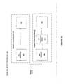
- FIG. 2is a block diagram of a circuit illustrating how front end voltage input channels are distributed to dedicated circuit paths: a transient detection, waveform capture path, and billing measurement path, to be scaled for processing by particular TED applications in accordance with one embodiment of the present disclosure.
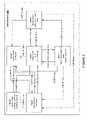
- FIG. 3 aillustrates an overall block diagram of the transient waveform detection system of the present disclosure, according to one embodiment.
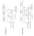
- FIG. 3 billustrates an exemplary sampled waveform processed in accordance with waveform sample periods, according to one embodiment.
- FIG. 4 ais a hardware configuration of a transient detector of the FPGA, according to one embodiment.
- FIG. 4 bis a hardware configuration of a transient detector of the FPGA, according to another embodiment.
- FIG. 5illustrates the operation of the transient detector and in particular the state machine's different states based upon the transient samples and threshold levels received by the IED.
- FIG. 6( a )-6( f )are graphs for illustrating the transient detector of transients at various states of the state machine of FIG. 4 a.
- intelligent electronic devicesinclude Programmable Logic Controllers (“PLC's”), Remote Terminal Units (“RTU's”), electric power meters, protective relays, fault recorders and other devices which are coupled with power distribution networks to manage and control the distribution and consumption of electrical power.
- PLC'sProgrammable Logic Controllers
- RTU'sRemote Terminal Units
- electric power metersprotective relays
- fault recordersand other devices which are coupled with power distribution networks to manage and control the distribution and consumption of electrical power.
- a meteris a device that records and measures power events, power quality, current, voltage waveforms, harmonics, transients and other power disturbances.
- Revenue accurate meters(“revenue meter”) relate to revenue accuracy electrical power metering devices with the ability to detect, monitor, report, quantify and communicate power quality information about the power that they are metering.
- a popular type of power meteris a socket-type power meter, i.e., S-base or Type S meter.
- the meteritself plugs into a socket for easy installation, removal and replacement.
- Other meter installationsinclude panel mounted, switchboard mounted, and circuit breaker mounted.
- Additional meter formsinclude switchboard drawout forms, substation panel metering forms, and A-base front wired forms.
- the power meterconnects between utility power lines supplying electricity and a usage point, namely, a residence or commercial place of business.
- the present disclosuredescribes an intelligent electronic device (IED), e.g., a power meter, configured to split and distribute front end voltage and current input channels, carrying front end voltages and currents, into separate circuit paths (revenue measurement circuit path, transient detection and measurement circuit path, and a waveform measurement circuit path) for the purpose of scaling and processing the front end voltages and currents by dedicated processors or processing functions.
- IEDintelligent electronic device
- the present disclosureis particularly directed to the configuration and operation of the transient detection and measurement circuit path.
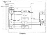
- FIG. 1is a block diagram of an intelligent electronic device (IED) 10 for monitoring and determining power usage and power quality for any metered point within a power distribution system and for providing a data transfer system for faster and more accurate processing of revenue and waveform analysis.
- IEDintelligent electronic device
- the IED 10 of FIG. 1includes a plurality of sensors 12 coupled to various phases A, B, C and neutral N of an electrical distribution system 120 , a plurality of analog-to-digital (A/D) converters 7 , 8 , 9 , including inputs coupled to the sensor 12 outputs, a power supply 15 , a volatile memory 19 , an non-volatile memory 17 , a multimedia user interface 13 , and a processing system that includes at least one central processing unit (CPU) 50 (or host processor) and one or more digital signal processors, two of which are shown, i.e., DSP 1 60 and DSP 2 70 .
- CPUcentral processing unit
- DSP 1 60 and DSP 2 70digital signal processor
- the IED 10also includes a Field Programmable Gate Array 80 which performs a number of functions, including, but not limited to, acting as a communications gateway for routing data between the various processors 50 , 60 , 70 , receiving data from the A/D converters 7 , 8 , 9 performing transient detection and capture and performing memory decoding for CPU 50 and the DSP processor 60 .
- the FPGA 80is internally comprised of two dual port memories to facilitate the various functions, as will be described further below.
- the plurality of sensors 12sense electrical parameters, e.g., voltage and current, on incoming lines, (i.e., phase A, phase B, phase C, neutral N), from an electrical power distribution system.
- electrical parameterse.g., voltage and current
- A/D converters 7 , 8 , 9are respectively configured to convert an analog voltage output from the sensors 12 to a digital signal that is transmitted to a gate array, such as Field Programmable Gate Array (FPGA) 80 .
- FPGAField Programmable Gate Array
- the digital signalis then transmitted from the FPGA 80 to the CPU 50 and/or one or more DSP processors 60 , 70 to be processed in a manner to be described below.
- the CPU 50 or DSP Processors 60 , 70are configured to operatively receive digital signals from the A/D converters 7 , 8 and 9 (see FIG. 1 ) to perform calculations necessary to determine power usage and to control the overall operations of the IED 10 .
- CPU 50 , DSP 1 60 and DSP 2 70may be combined into a single processor, serving the functions of each component.
- the digital samples, which are output from the A/D converters 7 , 8 , 9are sent directly to the CPU 50 or DSP processors 60 , 70 , effectively bypassing the FPGA 80 as a communications gateway.
- the power supply 15provides power to each component of the IED 10 .
- the power supply 15is a transformer with its primary windings coupled to the incoming power distribution lines and having windings to provide a nominal voltage, e.g., 5 VDC, +12 VDC and ⁇ 12 VDC, at its secondary windings.
- powermay be supplied from an independent power source to the power supply 15 .
- powermay be supplied from a different electrical circuit or an uninterruptible power supply (UPS).
- UPSuninterruptible power supply
- the power supply 15can be a switch mode power supply in which the primary AC signal will be converted to a form of DC signal and then switched at high frequency, such as, for example, 100 Khz, and then brought through a transformer to step the primary voltage down to, for example, 5 Volts AC. A rectifier and a regulating circuit would then be used to regulate the voltage and provide a stable DC low voltage output.
- Other embodiments, such as, but not limited to, linear power supplies or capacitor dividing power suppliesare also contemplated.
- the multimedia user interface 13is shown coupled to the CPU 50 in FIG. 1 for interacting with a user and for communicating events, such as alarms and instructions to the user.
- the multimedia user interface 13preferably includes a display for providing visual indications to the user.
- the displaymay be embodied as a touch screen, a liquid crystal display (LCD), a plurality of LED number segments, individual light bulbs or any combination.
- the displaymay provide information to the user in the form of alpha-numeric lines, computer-generated graphics, videos, animations, etc.
- the multimedia user interface 13further includes a speaker or audible output means for audibly producing instructions, alarms, data, etc.
- the speakeris coupled to the CPU 50 via a digital-to-analog converter (D/A) for converting digital audio files stored in a memory 19 or non-volatile memory 17 to analog signals playable by the speaker.
- D/Adigital-to-analog converter
- An exemplary interfaceis disclosed and described in commonly owned U.S. application Ser. No. 11/589,381, now U.S. Pat. No. 8,442,660, entitled “POWER METER HAVING AUDIBLE AND VISUAL INTERFACE”, which claims priority to U.S. Provisional Patent Appl. No. 60/731,006, filed Oct. 28, 2005, the contents of which are hereby incorporated by reference in their entireties.
- the IED 10will support various file types including but not limited to MicrosoftTM WindowsTM Media Video files (.wmv), MicrosoftTM Photo Story files (.asf), MicrosoftTM WindowsTM Media Audio files (.wma), MP3 audio files (.mp3), JPEG image files (.jpg, .jpeg, .jpe, .jfif), MPEG movie files (.mpeg, .mpg, .mpe, .m1v, .mp2v .mpeg2), MicrosoftTM Recorded TV Show files (.dvr-ms), MicrosoftTM WindowsTM Video files (.avi) and MicrosoftTM WindowsTM Audio files (.wav).
- MicrosoftTM WindowsTM Media Video files(.wmv)
- MicrosoftTM Photo Story files(.asf)
- MicrosoftTM WindowsTM Media Audio files.wma
- MP3 audio files.mp3 audio files
- JPEG image files.jpg, .jpeg, .jpe, .jfif
- MPEG movie files(.mp
- the IED 10further comprises a volatile memory 19 and a non-volatile memory 17 .
- volatile memory 19will store the sensed and generated data for further processing and for retrieval when called upon to be displayed at the IED 10 or from a remote location.
- the volatile memory 19includes internal storage memory, e.g., random access memory (RAM), or removable memory such as magnetic storage memory; optical storage memory, e.g., the various known types of CD and DVD media; solid-state storage memory, e.g., a CompactFlash card, a Memory Stick, SmartMedia card, MultiMediaCard (MMC), SD (Secure Digital) memory; or any other memory storage that exists currently or will exist in the future.
- RAMrandom access memory
- removable memorysuch as magnetic storage memory
- optical storage memorye.g., the various known types of CD and DVD media
- solid-state storage memorye.g., a CompactFlash card, a Memory Stick, SmartMedia card, MultiMediaCard (MMC), SD (Secure Digital)
- the IED 10will include a communication device 32 for enabling communications between the IED, and a remote terminal unit, programmable logic controller and other computing devices, microprocessors, a desktop computer, laptop computer, other meter modules, etc.
- the communication device 32may be a modem, network interface card (NIC), wireless transceiver, etc.
- the communication device 32will perform its functionality by hardwired and/or wireless connectivity.
- the hardwire connectionmay include but is not limited to hard wire cabling e.g., parallel or serial cables, RS232, RS485, USB cable, FirewireTM (1394 connectivity) cables, Ethernet, and the appropriate communication port configuration.
- the wireless connectionwill operate under any of the various known wireless protocols including but not limited to BluetoothTM interconnectivity, infrared connectivity, radio transmission connectivity including computer digital signal broadcasting and reception commonly referred to as Wi-Fi or 802.11.X (where x denotes the type of transmission), satellite transmission or any other type of communication protocols, communication architecture or systems currently existing or to be developed for wirelessly transmitting data including spread spectrum 900 MHz, or other frequencies, ZigbeeTM, WiFiTM, or any mesh enabled wireless communication.
- BluetoothTM interconnectivityinfrared connectivity
- radio transmission connectivityincluding computer digital signal broadcasting and reception commonly referred to as Wi-Fi or 802.11.X (where x denotes the type of transmission), satellite transmission or any other type of communication protocols, communication architecture or systems currently existing or to be developed for wirelessly transmitting data including spread spectrum 900 MHz, or other frequencies, ZigbeeTM, WiFiTM, or any mesh enabled wireless communication.
- the IED 10may communicate to a server or other computing device via a communication network.
- the IED 10may be connected to a communications network, e.g., the Internet, by any known means, for example, a hardwired or wireless connection, such as dial-up, hardwired, cable, DSL, satellite, cellular, PCS, wireless transmission (e.g., 802.11a/b/g), etc.
- the networkmay be a local area network (LAN), wide area network (WAN), the Internet or any known network that couples a plurality of computers to enable various modes of communication via network messages.
- the serverwill communicate using the various known protocols such as Transmission Control Protocol/Internet Protocol (TCP/IP), File Transfer Protocol (FTP), Hypertext Transfer Protocol (HTTP), etc.
- TCP/IPTransmission Control Protocol/Internet Protocol
- FTPFile Transfer Protocol
- HTTPHypertext Transfer Protocol
- the serverwill further include a storage medium for storing a database of instructional videos, operating manuals, etc., the details of which will be described in detail below.
- the IED 10will also have the capability of not only digitizing the waveform, but storing the waveform and transferring that data upstream to a central computer, e.g., a remote server, when an event occurs such as a voltage surge or sag or a current short circuit.
- This datawill be triggered and captured on an event, stored to memory, e.g., non-volatile RAM, and additionally transferred to a host computer within the existing communication infrastructure either immediately in response to a request from a remote device or computer to receive said data or in response to a polled request.
- the digitized waveformwill also allow the CPU 50 to compute other electrical parameters such as harmonics, magnitudes, symmetrical components and phasor analysis. Using the harmonics, the IED 10 will also calculate dangerous heating conditions and can provide harmonic transformer derating based on harmonics found in the current waveform.
- the IED 10will execute an e-mail client and will send e-mails to the utility or to the customer direct on an occasion that a power quality event occurs. This allows utility companies to dispatch crews to repair the condition.
- the data generated by the metersare used to diagnose the cause of the condition.
- the datais transferred through the infrastructure created by the electrical power distribution system.
- the email clientwill utilize a POP3 or other standard mail protocol.
- a userwill program the outgoing mail server and email address into the meter.
- An exemplary embodiment of said meteringis available in U.S. Pat. No. 6,751,563 which all contents thereof are incorporated by reference herein. As disclosed in U.S. Pat. No. 6,751,563, the meter is installable as a socket type meter, a panel mounted meter, a switchboard mounted meter, or a circuit breaker meter.
- the techniques of the present disclosurecan be used to automatically maintain program data and provide field wide updates upon which IED firmware and/or software can be upgraded.
- An event commandcan be issued by a user, on a schedule or by digital communication that will trigger the IED 10 to access a remote server and obtain the new program code. This will ensure that program data will also be maintained allowing the user to be assured that all information is displayed identically on all units.
- the IED 10also includes an operating system and micro instruction code.
- the various processes and functions described hereinmay either be part of the micro instruction code or part of an application program (or a combination thereof) which is executed via the operating system.
- the IED 10 of the present disclosurecan compute a calibrated VPN (phase to neutral) or VPP (phase to phase) voltage RMS from VPE (phase to earth) and VNE (neutral to earth) signals sampled relative to the Earth's potential, where Phase P may be, for example, Phase A, B or C of a three phase system 120 .
- Calibrationinvolves removing (by adding or subtracting) an offset (o, p) and scaling (multiplying or dividing) by a gain (g, h) to produce a sampled signal congruent with the original input signal.
- the RMSis the Root-Mean-Square value of a signal, the square root of an arithmetic mean (average of n values) of squared values. Properly combined, one representation of this formula is:
- V AN⁇ n ⁇ ( g ⁇ ( V AE - o ) - h ⁇ ( V NE - p ) ) 2 n
- V ANis the voltage from phase A to neutral
- V AEis the voltage measured from phase A to earth
- V NEis the voltage measured from neutral to earth
- nis the number of values taken.
- V ANg 2 ( ⁇ n ⁇ V AE 2 - 2 ⁇ o ⁇ ⁇ n ⁇ V AE n + o 2 ) - 2 ⁇ gh ( ⁇ n ⁇ V AE ⁇ V NE - o ⁇ ⁇ n ⁇ V NE - p ⁇ ⁇ n ⁇ V AE n + op ) + h 2 ( ⁇ n ⁇ V NE 2 - 2 ⁇ p ⁇ ⁇ n ⁇ V NE n + p 2 )
- V ANis the voltage from phase A to neutral
- V AEis the voltage measured from phase A to earth
- V NEis the voltage measured from neutral to earth
- nis the number of values taken.
- FIG. 2is a block diagram of a circuit illustrating how front end voltage input channels are distributed to dedicated circuit paths: transient detection 11 , waveform capture 16 , and billing measurement 30 , to be scaled for processing by particular TED 10 applications in accordance with one embodiment of the present disclosure.
- the present disclosureis particularly directed to the transient detection path 11 .
- voltage channelsare applied to an input of a resistance divider 5 of the circuit.
- the resistance divider 5reduces potential high voltage levels of the voltage channels to allow for proper handling by the various circuits.
- the resistance divider 5provides a reduced voltage level which is then split at Point “28” into three circuit paths, transient detection 11 , waveform capture 16 , and billing measurement 30 , to be scaled for processing by particular IED 10 applications in accordance with embodiments of the present disclosure. It should be understood that the number of circuit paths used can vary depending on the number of particular IED applications that are intended to be performed.
- the three circuit paths 11 , 16 and 30 shown in FIG. 2correspond to respective applications of the IED 10 including; transient capture/scaling circuit, associated with path 11 , waveform capture, associated with path 16 and revenue measurement, associated with path 30 .
- a transient signal conditioning and analog to digital conversion path 11is configured to perform signal conditioning and scaling operations on the electrical distribution system 120 three-phase input voltage channels Va, Vb, Vc to enable the detection and measurement of transients on the conditioned/scaled input voltage channels by a transient measurement circuit, to be described below.
- the transient capture/scaling circuit path 11performs signal conditioning and scaling on a three-phase input voltage channel, i.e., Va, Vb, Vc
- the circuitryis duplicated for each voltage phase, Va, Vb, Vc and Vn (neutral) although only one circuit is shown.
- the transient capture/scaling circuit path 11singles out high speed voltage events on the conditioned/scaled input voltage channels that would otherwise be missed by the waveform capture analog-to-digital converters (ADCs) 8 a of the waveform capture circuit 16 .
- the transient capture/scaling circuit path 11is converting at a relatively low bit resolution, but at high speed. This will enable the TED to capture a wide dynamic range of very high speed signals. This is opposed to the waveform capture circuit in which the bit resolution of the A/D converters is high. Standard technology does not allow for high resolution and high-speed conversion. Thus, by utilizing both paths, the meter will be able to record accurate power measurements and capture high speed transients.
- the transient capture/scaling circuit path 11includes four circuit elements as shown in FIG. 2 , a first amplifier 14 having a unit gain, a follower 27 , a second amplifier 13 and an A/D converter 7 A. Scaling and offset operations are performed by the combination of the first amplifier 14 , follower 27 and the second amplifier 13 . The scaled and offset voltages, output from the second amplifier 13 , are supplied to the dedicated A/D converter 7 A which outputs a digitized/scaled output voltage to FPGA 80 (See FIG. 1 ).
- a resistor divider at the output of the first amplifier 14applies a gain adjustment to the input voltage channels, Va, Vb and Vc.
- the gain adjustmentis set to provide an output amplified voltage in an acceptable range of the A/D converter 7 A.
- the follower 27separates the gain stages and the offset of the first and second amplifiers 13 , 14 .
- the follower 27provides isolation between the first and second amplifiers 13 , 14 so that there is no detrimental loading effect from amplifier 13 .
- the offset adjust circuitry of amplifier 13must be isolated from amplifier 14 . This also allows each amplifier 13 , 14 to be independently adjusted. Without follower 27 , a change in offsetting would adversely affect the gain of the previous stage, i.e., the gain provided from amplifier 14 .
- the second amplifier 13offsets the transient voltage which is supplied from the amplifier 13 as input to the A/D converter 7 A. This is required in that the A/D converter 7 A only accepts a unipolar input voltage, for example, in the range of 0 to 2 volts.
- the A/D converter 7 Ais representative of a block of A/D converters.
- the A/D converter 7 Areceives conditioned/scaled transient voltages Va, Vb, Vc and Vn as input and outputs a digitized/scaled output voltage. It is noted that transient voltages are only measured on Vn in a phase-to-neutral measurement mode. In a phase-to-phase measurement mode, phase-to-phase transients do not use Vn as an input.
- the transient capture/scaling circuit path 11is capable of scaling a wide range of input voltages on the voltage channel inputs, Va, Vb, Vc.
- the transient capture/scaling circuit path 11can scale input voltages of ⁇ 1800 volts peak to peak. It should be appreciated that the actual voltage dynamic range of the transient capture/scaling circuit path 11 can be modified as per customer specifications. It should be noted that the transient capture/scaling circuit path 11 is configured to handle peak to peak voltages.
- the transient capture/scaling circuit path 11has a very high bandwidth, on the order of 10 Mhz, that can be clocked substantially in the range from 1 MHz to 50 MHz or greater.
- the combination of the transient scaling circuit's scaling capabilities (for over ranging voltage), high bandwidth and very high sample ratemake possible accurate measurement and capture of the high speed transient without distorting the transient characteristics.
- an input channel voltage range of ⁇ 1800 peak to peak voltsis reduced by a resistor divider 5 . Reduction is from ⁇ 1800 peak to peak volts to ⁇ 5.5 peak to peak volts.
- the transient capture/scaling circuit path 11has a gain of 1 ⁇ 5.53 (i.e., 0.18).
- a positive offset voltage of 1.00 voltsis added to the signal output of amplifier 14 to ensure that the output voltage of amplifier 13 is always positive.
- a +/ ⁇ 5.5 peak to peak volt input to amplifier 14results in a output voltage in the range of +/ ⁇ 0.997 volts which ensures that the output voltage of amplifier 13 will be positive.
- Amplifier 13provides an offset voltage of 1.00 v so that an output range of amplifier 13 is in the range of 0.00446v to +1.9954v, to be provided as input to the A/D converter 7 A. It should be appreciated that the afore-mentioned voltage scaling operations, described above, are needed for the high speed A/D converter 7 A.
- A/D converter 7 AOne non-limiting circuit component that can be used for A/D converter 7 A is a low power, 8 bit, 20 MHz to 60 MHz A/D converter.
- One representative component having these attributesis the ADC08L060, which is commercially available from National Semiconductor, Santa Clara, Calif. It should be understood, however, that the IED 10 of the present disclosure is not limited to any particular component for performing A/D conversion.
- the transient capture/scaling circuit path 11is necessary to scale down the input voltage channels so that the input voltage range of the A/D converter 7 A, can be met which may be implemented with a ADC08L060 converter or any suitable alternative.
- Use of the ADC08L060 component or any suitable alternativeguarantees that a high speed sampling rate, on the order of 50 MHZ or greater will be possible for making transient measurements, including making transient measurements, on the scaled down input voltage channels. Details pertaining to the scaling circuitry is described more fully in co-pending U.S. patent application Ser. No. 12/075,690 filed on Mar. 13, 2008, now U.S. Pat. No.
- waveform capture/scaling circuit path 16receives a three-phase power input. Accordingly, the circuitry 16 is duplicated for each voltage phase, Va, Vb, Vc and Vn (neutral) of the three-phase power input. The waveform capture scaling circuit path 16 is further duplicated for an auxiliary input, Vaux.
- the waveform capture scaling circuit 16is provided with a scaled input voltage signal from the resistor divider 5 , which is common to all paths (i.e., transient capture/scaling circuit path 11 , waveform capture circuitry path 16 and billing circuitry path 30 ).
- the scaled input voltage signalis supplied as input to amplifier 18 , which isolates the multiplexer 31 from the transient capture/scaling circuit path 11 and billing circuitry path 30 by amplifier 18 .
- the waveform capture circuit 16receives several channels at input amplifier 18 for scaling. Some of the scaled channels, which are output from the amplifier 18 , at point “29”, are then provided as input to a multiplexer 31 . That is, not all input channels go the multiplexer 31 . Because the A/D converter 8 A is limited to six channels, the following signal pairs are multiplexed: Va or Vaux, Vc or Vb, Ia or Ib. Channels, Vn, In and Ic go directly from the amplifier to the driver 4 . The multiplexer 31 multiplexes the scaled channels for the A/D converter 8 A that is dedicated to the waveform capture scaling circuit 16 .
- the multiplexed signalswhich are output from multiplexer 31 , are provided as input to the driver 4 , which is followed by the A/D converter 8 A.
- the A/D converter 8 Ais actually comprised of a block of A/D converters. More particularly, A/D converter 8 A is a multi-channel A/D converter for converting both voltage and current inputs. To allow for conversion of all of the channels, the multiplexer 31 selects from among the various inputs and a conversion is performed in two steps.
- the input channelsgo into the FPGA 80 (see FIG. 1 ) to the DSP Processor 70 .
- the DSP Processor 70provides digital signal processing and the waveform analysis is focused on seeing more of the signal even though accuracy is reduced as there is more interest in quality of power and not accuracy.
- both A/D converters for the waveform scaling analysis circuit 16 and for the billing measure circuit path 30each have 16 bit resolution
- there is a difference in the range of input for the revenue A/D converter 9(A/D converter 9 is a block of A/D converters that includes at least one A/D converter) and for the waveform capture A/D converter 8 A due to the difference in the scaling input for each of these two converters. So the range of input of both the A/D revenue converter 9 and the A/D waveform capture converter 8 are different from each other.
- a zero crossing circuit 26which may be connected to the waveform, capture circuit 16 in certain embodiments.
- the zero crossing circuit 26is only applicable to input voltage channels Va, Vb, Vc and Vaux (auxiliary voltage input).
- the operation of the zero crossing circuit 26 of FIG. 2is as follows, according to one embodiment.
- the input voltage channels, which contain both fundamental and harmonic sinusoidal signals, after amplification in amplifier 18are fed into a comparator 25 .
- the comparator 25produces a high output when the input is positive, and a low output when the signal is negative, thus transforming the input signal into a pulse train which transitions at each zero crossing.
- comparator 25is fed into whichever processor includes the firmware for processing the zero crossing application. This could be the CPU 50 (Host Processor) or DSP Processor 70 or DSP Processor 60 or FPGA 80 .
- Frequency computationis performed using the output of comparator 25 .
- the processordetects the time of each transition, and computes the duration between each transition.
- the presence of harmonics in the signalis such that the durations might significantly differ from that expected from the pure fundamental. Durations that are significantly shorter or longer than expected are ignored; durations that fall within acceptable limits are counted and accumulated. Periodically, the accumulated duration is divided by the count of durations, giving an average duration, from the inverse of which the average frequency can be computed.
- Sampling and computationscan occur in one of two ways, based on the frequency computation. In situations where a fixed sample rate is used, computations are based on the number of samples that would be taken over the period of the computed frequency; as the frequency varies, the number of samples in a cycle varies, while maintaining a fixed sample rate. Alternatively, in situations where synchronous sampling is needed, the sample period is computed as the desired fraction of the period of the computed frequency; as the frequency varies, the sample rate varies while maintaining a fixed number of samples per cycle.
- the revenue measurement/scaling circuit path 30is operable to measure input voltage phases: Va, Vb, Vc and Vn and input current channels Ia, Ib, Ic and In.
- Revenue measure circuit path 30is comprised of a calibration switch 21 , an amplifier 22 , a driver 23 and A/D converter 9 A.
- FIG. 3 aillustrates an overall block diagram of the transient waveform detection system 300 of the present disclosure, according to one embodiment.
- the transient waveform detection systemprovides speed and scaling for over ranging voltage and a high bandwidth to compliment the high transient sampling rate, on the order of 50 Mhz.
- the systemalso provides an over range capability, on the order of +/ ⁇ 1800 peak to peak volts (ppv).
- FIG. 3 athere is shown three voltages Va, Vb, Vc and a neutral Vn, which may be supplied from a power distribution system 120 , i.e. , power grid.
- the three voltagesare input to a high bandwidth transient capture A/D converter circuit 7 that can be clocked at 50 MHz or greater.
- the transient capture A/D converter circuit 7is required to operate at a minimum sampling rate of at least 50 MHZ to capture the voltage transients.
- the four input analog voltage channels, Va, Vb, Vc and Vnare simultaneously input to a waveform capture A/D converter circuit 8 A in FIG. 2 that has higher resolution and lower bandwidth, typically clocked between 2 KHz to 100 KHz.
- the transient waveform detection system 300operates at a system clock frequency of 61.44 Khz which corresponds to a waveform sample period of 16.67 microseconds.
- a graph of voltage (e.g., Va) vs. timeis shown whereby the time axis is divided in accordance with equidistant waveform sample periods.
- the waveform sample periodscorrespond to the system clock frequency, which in a preferred embodiment is 61.44 KHz. It should be understood, however, that 61.44 KHz is insufficient to detect transients which may occur in the sampled voltage (e.g., Va). Thus, a higher transient sampling rate is required, which is typically orders of magnitude higher than the system clock frequency of 61.44 KHz.
- the high bandwidth transient capture A/D converter circuit 7operates at or above 50 MHz to be able to capture transients as they occur in the sampled waveforms.
- each waveform sample periodis defined by a start and stop boundary.
- waveform sample period 3is defined by start boundary 3 and stop boundary 3.
- These boundariesdefine initialization and reset periods, respectively, for detecting transient information including peak and duration information, for example.
- each waveform sample perioddefines the boundaries of a new transient capture cycle.
- the high bandwidth transient capture A/D converter circuit 7samples the four input analog voltage channels Va, Vb, Vc and Vn and outputs digital samples of voltage transients 30 from the respective voltage channels to a field programmable gate array (FPGA) 80 .
- FPGAfield programmable gate array
- the transient capture A/D converter 7may be implemented as an ADC08L060 which is a low power, 8 bit, 10 MHz to 60 MHz A/D converter. It is understood that the IED 10 of the present disclosure is not limited to any particular component for performing A/D conversion.
- the ADC08L060represents one example of an A/D component suitable for use with the present invention.
- the ADC08L060is commercially available from National Semiconductor, Santa Clara, Calif.
- FPGA 80supports digital sampling in excess of 100 MHz. Threshold voltage levels for use as one input to a comparator for determining the presence or absence of a transient are communicated from the CPU 50 to the FPGA via a Host bus 51 . In another embodiment, DSP Post Processor 112 provides the threshold voltage levels.
- the FPGA 80includes a transient and waveform controller, identifiable in FIG. 3 a as transient detect controller 114 for controlling the sampling of both the waveform data 32 by the waveform capture A/D's 8 A and the sampling of the transient 30 by the transient capture A/D's 7 .
- the Transient detect controller 114is described in more detail below.
- the FPGA 80is shown to receive digital samples 30 of the voltage transients in real-time output from the transient capture A/D converter 7 . Based upon the voltage thresholds set by the CPU 50 , the FPGA 80 identifies and stores a single peak transient value along with its associated duration during each waveform sample period of the IED 10 . At the end of each waveform sample period, the single peak transient value and its associated duration are passed to the DSP Post Processor 112 on transient and waveform data bus 113 in parallel along with waveform data 32 transferred to FPGA 80 from the waveform capture A/Ds 8 A under control of the waveform capture control 122 of FPGA 80 .
- the DSP Post Processor 112correlates the received peak transient value and associated duration (referred to hereafter as transient data) to the lower bandwidth sampled waveform data 32 and replaces the received waveform data 32 with the corresponding transient data to produce merged waveform data.
- the DSP Post Processor 112also retains a copy of the unmerged lower bandwidth sampled waveform data 32 and transient data).
- the merged waveform datais then passed to the CPU 50 by DSP Post Processor 112 via a dual port memory 118 in the FPGA 80 .
- the CPU 50stores the merged waveform and makes it available for presentation to the user. It is appreciated that the CPU 50 also has access to the unmerged waveform data 32 and transient data via the DSP Post Processor 112 .
- FPGA 80can be configured to capture complete transient waveforms in its transient capture internal memory 116 or external memory 110 for large transient captures.
- the processis controlled by the transient detect controller 114 which is fully configurable. It is appreciated that in the presently described embodiment, the functionality of the transient detect controller 114 is designed into the FPGA 80 .
- transient samplesare captured to the transient capture internal memory 116 or transient capture external memory 110 whenever a transient rises above the transient threshold.
- the transient capture internal memory 116 or external memory 110effectively stores a snapshot of a complete transient waveform.
- a complete transient waveformcomprises an array of (x,y) pairs denoting amplitude and time from the point in time that a transient rises above the transient threshold to the point in time that the same transient falls below the same threshold.
- the Transient Capture Memory data for a given waveform sample periodcan be read by CPU 50 via Host Bus 51 and stored in a transient snapshot log.
- both negative and positive transient samples received from mux/subtractor 202are converted to their absolute value before any other processing occurs. More specifically, the absolute value module 206 converts both the negative and positive transient samples output from the mux/subtractor 202 . Consequently, the Absolute value module 206 outputs only positively signed transients to threshold comparator 204 (CMP B), peak comparator 210 , and peak latch 212 . This allows the peak comparator 210 to find the largest transient irrespective of whether the transient was a negative or positive peak.
- CMP Bthreshold comparator 204
- the sign of the transient sampleis also stored as a flag as additional information to indicate if the sample was positive or negative.
- the absolute value and associated sign informationis then passed to DSP Processor 70 so that the originally detected transient characteristics (e.g., sign and magnitude) can be restored.
- the FPGA 80is configured via firmware to provide the various transient detector functions detailed below.
- the transient detect controller 114 of the FPGA 80includes in one embodiment a multiplexer/subtractor circuit 202 (mux./subtractor).
- the mux/subtractor 202accepts the digital samples of the voltage transients in real-time from the A/D converter 7 and determines either phase to phase voltages or phase to neutral voltages.
- a mode select 201is provided to the mux/subtractor 201 to receive a signal from the CPU 50 (or at least one DSP Processor) to select the mode in which the mux/subtractor 202 will operate. There are three modes of operation. The first mode determines whether the transient detect controller is on or off.
- the second or third modescan be selected only when the first mode is set to the “on” state.
- the second modedetermines phase to neutral voltage.
- the third modedetermines phase to phase voltage.
- These modesare firmware implemented in the FPGA 80 .
- the Mode registercontrols the state of a multiplexer so that the subtractor is either always subtracting the neutral phase from the other phases to create phase-to-neutral channels or selects another phase to create phase-to-phase transient channels.
- the transient detect controller 114 of the FPGA 80further includes a threshold comparator 204 (CMP B) which detects if a transient is above a threshold set by the CPU 50 .
- the thresholdcan be set instead by at least one DSP Processor 70 .
- a state machineis any device that stores the status of something at a given time and can operate on input to change the status and/or cause an action or output to take place for any given change.
- the transient detect controller 114includes a single state machine 206 , as shown in FIG. 4 a .
- the state machine 206controls the process of selecting peak values of transients and a second state machine controls the transfer of the peak transient sample captured to at least one DSP Processor 70 .
- State (0)corresponds to a state where a transient is determined to be above a positive voltage threshold and a peak for the first transient during the present waveform sample period has occurred.
- the positive voltage thresholdis communicated from the CPU 50 to the FPGA 80 via a Host bus 51 (see FIG. 3 a ).
- State (1)corresponds to a state where the transient is determined to be below the positive threshold and not at a waveform sample boundary.
- State (2)corresponds to a state where a second transient occurred during a waveform sample period which has a higher peak value than the first that was captured during the same waveform sample period which were above the positive threshold and not at a waveform sample boundary.
- State (3)corresponds to a state where the transient was determined to be above the positive threshold but below a previously captured transient peak and not at a waveform sample boundary.
- State (4)corresponds to a state where the transient is determined to be below the positive threshold and a waveform sample boundary.
- State (5)corresponds to a state where the transient continues above the positive threshold at the waveform sample boundary.
- the transient detect controller 114 of the FPGA 80includes a duration counter 208 .
- the threshold comparator 204(CMP B) enables the duration counter 208 whenever a transient goes above the threshold set by the CPU 50 (or the DSP Processor 70 ).
- the duration counter 208remains enabled as long as the transient is above the threshold so that the transient duration within a waveform sample period can be measured.
- the state machine 206clears the duration counter 208 at the start of each waveform sample period then whenever a transient exceeds the threshold level during a waveform sample period, the duration counter 208 is incremented at the transient sampling rate of 50 MHz.
- threshold comparator 204CMP B
- duration counter 208the duration counter 208 to measure the duration of the transient.
- the measured transient duration valueis passed on to the DSP Processor 70 along with the associated transient peak value.
- the peak comparator 210detects the peak value Pa of a transient that may occur during a waveform sample period. As shown in FIG. 4 a , the incoming transient sample is routed to the A input of the Peak Comparator 210 (CMP A), where it is compared to a previously latched peak transient sample. If the incoming transient sample is greater than the previously latched peak transient sample it enables the peak latch 212 which outputs the signal at output Q of peak latch 212 and feeds it back to the B input of the peak comparator 210 (CMP A) for comparison with the next incoming transient sample.
- CMP APeak Comparator 210
- the transient clock (Tclk) 211 of the peak latch 212is a high speed clock that is programmed by the FPGA 80 to clock the peak latch.
- the peak latchcan be clocked at a rate of 50 MHz.
- the Transient detect controller 114further includes a transient capture memory 214 .
- the transient capture memory 214can be internal or external to the FPGA 80 in different embodiments. All transient samples above the threshold are stored in the transient capture memory 214 under control of the FPGA 80 . As previously noted, in other embodiments, the same process may be performed under control of the DSP processor 70 or the CPU 50 . Digital transient samples are written to the transient capture memory 214 from the beginning of a waveform sample period.
- the transient detect controller (TDC) 114If at the end of a given waveform sample period, it is determined that no transients occurred, the transient detect controller (TDC) 114 resets the write memory counter causing the data captured during the given waveform sample period, which did not contain a transient, to be overwritten. In a given waveform sample period, if a transient is detected, the TDC 114 continues to capture transient samples whether they are above or below the threshold until the memory in use is full. In another words whenever a transient is detected a snapshot of the transient event and what occurred around the transient event is captured for presentation to an end user.
- the transient detect controller (TDC) 114monitors the state of the Transient Capture Memory 214 and when it is full sets a flag to CPU 50 to inform CPU 50 that the transient sample may be read from the transient capture memory 214 for presentation to an end user. After reading the transient sample data from the transient capture memory 214 , CPU 50 sets a flag to the TDC 114 to indicate that the memory is available for another capture. TDC 114 also sets a flag to DSP 70 when data is first written to memory so that the DSP 70 can record a time stamp of the waveform sample time when the memory capture of the transient began. DSP 70 passes the time stamp to CPU 50 so it can co-ordinate in time the presentation of the transient waveform image with other waveform and peak transient data.
- TDCtransient detect controller
- the intermediate holding register 215is a temporary holding buffer for storing various values collected during each waveform sample period.
- the FPGA 80At the start of each waveform sample period (see FIG. 3 b ), the FPGA 80 generates a Waveform Sync 209 signal that the state machine 206 uses to reset the peak latch 212 and the duration counter 208 for the beginning of a new transient capture cycle.
- the state machine 206monitors the outputs of peak comparator 210 and threshold comparator 204 (CMP B) to detect when a transient has exceeded the set threshold and when it has fallen below the set threshold so that it can detect if transients may have occurred during the current waveform sample period. The state machine can also identify if a transient persists over more than one waveform sample period. If a detected transient is above the threshold, the threshold comparator 204 (CMP B) triggers, via the state machine 206 , the start of the peak detect circuitry.
- the peak detect circuitryincludes a peak comparator 210 (CMP A), a peak latch 212 and a duration counter 208 along with the transient waveform capture circuitry 7 (See FIG. 1 ), as described above, which is performed at a transient sampling rate of at least 50 MHz.
- the transient detect controller 114 and specifically state machine 206has several outputs to control the acquisition of transient data including: Latch peak which is a signal which latches the peak value of the present transient in the intermediate holding register 215 after the transient has dropped below the threshold or at the end of a waveform sample waveform sample period, Latch sign Bit and Latch duration are signals which latch the sign and duration in the intermediate holding register 215 at the same time that the peak value of the transient is latched there.
- Latch results, Continue Flag and New Flag, Resetare signals generated at the end of the waveform sample period. Latch results, latches the final results which have been temporarily stored in the intermediate hold register 215 .
- the signal Continue Flagindicates that the transient is still above threshold when crossing into the next waveform sample period so that the total duration of the transient can be calculated.
- New Flagis set if a new transient occurred in the cycle.
- the New Flagindicates to the firmware that if Continue Flag was set previously that the peak and duration stored at the end of the next cycle is from a new transient and not part of the continuation of the transient that started in the previous cycle. This supports that the largest transient is found and that the durations are not associated with the wrong transient. For a better understanding see the examples below.
- the Reset signalis used to clear the counters and registers at the appropriate time in preparation for the next transient capture. These values are initialized to low (e.g., 0 ) at the beginning of each waveform sample period and set high (e.g., 1 ) by the state machine upon the detection of the appropriate condition.
- the duration counter 208is started. As the transient falls below the predetermined threshold, the state machine 206 transfers the duration counter 208 value to the intermediate holding register 215 and resets the duration counter to zero in preparation for the next transient occurrence. At the point in time that the detected transient falls below the predetermined threshold, the duration counter is disabled from counting due to the change in state of the comparator (CMP B). At this point in time, the state machine 206 stores the duration counter 208 value which was measured while the transient was occurring by generating the Latch Duration signal output which latches the duration counter value in a temporary holding buffer, i.e., intermediate holding register 215 .
- the state machine 206resets the duration counter 208 , via the Reset signal output, to the CLR input of duration counter 208 in preparation for a new transient.
- the state machine 206latches the duration stored in the intermediate holding register 215 with the Results Latch signal output of state machine 206 to a final result Duration Results Latch. Otherwise, if a transient having a larger peak value does occur within a given waveform sample period, the new larger transient peak value and its associated duration value will overwrite the previous transient duration value stored in the intermediate holding register 215 under control of state machine 206 and at the end of the current waveform sample period state machine 206 stores the intermediate holding register 215 duration value to a final result duration latch 224 by outputting the Results Latch signal which is also used to latch the peak value and associated flags into result latches.
- the state machine 206also sets the “C” flag and writes it to a Results Latch so that the DSP Processor 70 can combine durations and compute the total duration and peak value if it is sustained over multiple waveform sample periods.
- the state machine 206 of the transient detect controller 114includes a Result Latches.
- the latched resultsare then transferred over a dedicated transient and waveform data bus to the DSP Processor 70 for further processing.
- FIG. 4 bthere is shown another emodiment of the transient detect controller 114 of FIG. 3 a .
- positive transient samplesare processed in a first processing path 401 and negative transient samples are processed in a separate second processing path 403 .
- the transient samplesare output directly from mux/subtractor 202 to block 251 which describes elements of the transient detect controller 114 shown in FIG. 4 a . It should be understood that in the present embodiment, block 251 operates in the identical manner described above, as shown in FIG. 4 a.
- the transient samplesare output directly from mux/subtractor 202 to 2's complement module 213 .
- the 2's complement module 213is configured to convert negative transient samples to positively signed transient samples to allow block 251 to process the negative transients in the manner described above.
- positive transientsare converted to negatively signed transients and are discarded in the negative processing path 403 . That is, the negatively signed transients will be below the threshold set in the threshold comparator 204 and are consequently discarded (i.e., not recognized as transients).
- both the negative and positive transient processing paths 401 , 403operate in parallel so that if both large positive and large negative transients occur, both will be captured and transferred to CPU 50 via one of the four high speed serial channels that go between FPGA 80 and CPU 50 .
- FIG. 5illustrates the operation of a state machine 206 incorporated into transient detect controller.
- FIG. 5illustrates the state machine's 206 different states based upon the transient samples and threshold levels received by the IED 10 .
- FIGS. 6( a )-6( f )provide illustrative non-limiting examples of various waveform samples including transients to illustrate how the state machine 206 of the IED 10 of the present disclosure operates to detect and save the transient information.
- a “transient”is defined as a waveform that crosses a positive voltage threshold for some period of time and then transitions below the positive voltage at a later point in time.
- FIG. 6( a )shows a first example of a transient waveform sample, discussed in the context of the various states of the state diagram of state machine 206 , as illustrated in FIG. 5 .
- the transient waveform at the initial (left hand) boundary of waveform sample period 1is shown to be below the positive voltage threshold level for at least one previous waveform sample period, and above the negative voltage threshold level, causing the state machine to start out in state 4.
- State (4)corresponds to a state where the transient is determined to be below the positive threshold and at a waveform sample boundary.
- the transient waveformis then shown to rise until it is crosses the positive threshold at point “x”.
- state (0)corresponds to a state where a transient is determined to be above a positive voltage threshold and a peak for the first transient during the present waveform sample period has occurred.
- the peakis determined to be the first transient sample (i.e., peak value) upon crossing the positive threshold.
- the first transient samplei.e., peak value
- the transient waveform value, in waveform sample period 1continues to rise until it reaches peak value Pa, as shown in FIG. 6( a ) . It is noted that while the state machine 206 is in State (0), the state machine 206 continuously obtains and saves ordinate values of the transient to peak latch 212 (see FIG. 4 a ) and compares the most recently received ordinate value with the most recently saved peak value, currently stored in peak latch 212 . Whenever an ordinate value is determined to be higher than the currently saved peak value in peak latch 212 , the, ordinate value replaces the currently saved value in the peak latch 212 . At the end of waveform sample period 1, the transient value stored in the Peak latch 212 is transferred to the intermediate holding register 215 (see FIG. 4 a ). This value is considered to be the peak value for waveform sample period 1.
- the transient waveform detection system of the present disclsourerecords both the peak values of the transient waveform in addition to the duration of the entire transient. Duration is defined herein from the point in time a transient crosses above the positive threshold to the point in time the transient falls below the same positive threshold. For example, in FIG. 6( a ) , the transient duration for the transient having a peak value Pa, is labeled “Da”. Transient duration is measured by the duration counter 208 , as shown in FIG. 4 a.
- State (1)defines a state where the transient is determined to be below the positive threshold and not at a waveform sample period boundary. In other words, the transient is somewhere between the left and right vertical boundary lines defining waveform sample period 1. The transient is shown to remain in State (1) until the end of waveform sample period 1.
- the state machine 206transfers the value stored in peak latch 212 to the intermediate holding register 215 .
- the value stored in the intermediate holding register 215is transferred to results latches 222 , 224 , 226 , 228 and 230 at the end of waveform sample period 1 as a final peak value (i.e., determined to be the highest peak value in the present waveform sample period, e.g., period 1).
- the outputs of the transient detect controller 114output a number of values at the end of the waveform sample period. These values include: the peak latch 222 having a value Pa (the highest peak value in the present waveform sample period), the duration latch 224 having a value Da (the duration associated with the value Pa), the sign latch 230 having a value of zero (0) since there was a positive peak transient value, the C (continue latch) 226 having a value of zero (0) since the peak transient did not continue through to the next waveform sample period (waveform sample period number 2 ) and the NF latch (new transient latch) 228 having a value of 1 since there was only one peak transient, Pa, during that waveform sample period for that transient.
- FIG. 6( b )illustrates a second non —limiting illustrative example of how the transient waveform detection system operates on an exemplary transient waveform.
- FIG. 6( b )illustrates a second non —limiting illustrative example of how the transient waveform detection system operates on an exemplary transient waveform.
- Each peak valuehas a respective associated duration of Da, Db and Dc.
- the first transientinitially rises above 0 volts in waveform sample period 1 and continues to rise but remains below the positive threshold level as it drops slightly. Since this spike is below the positive threshold and above the negative threshold, the state machine 206 recognizes that this is not a peak transient and consequently enters into State (4) at the left boundary of waveform sample period 1, indicating that the transient is below the positive threshold.
- the transientthen rises above the positive threshold at point “x1” to eventually reach a peak value of Pa.
- This first transient peak, waveform sample period Pais shown to have has an associated duration of Da.
- the state machine 206enters into State (0).
- point “z1”the transient drops below the positive threshold causing the state machine to transition from State (0) into State (1).
- the transientthen drops until it falls below the positive threshold at point “z2”. At this point the state machine 206 transitions from State (3) to State (1). While in State (1), the transient then rises above the positive threshold for the third time in waveform sample period 1 at point “x3”, with the state machine 206 transitioning back from State (1) to State (3).
- the state machine 206While in State (3), the transient eventually exceeds the previously highest recorded peak value Pa for the waveform sample period 1, the state machine 206 then transitions from State (3) to State (2). The state machine 206 remains in State (2) since the transient level is determined to be below the peak value Pa of the last saved transient for this transient and the waveform sample boundary has not been reached.
- the state machine 206recognizes and saves the new peak value Pc and replaces the old transient peak value Pa and its associated duration Da with the new transient peak value Pc and its associated duration Dc.
- the transientthen drops below the positive threshold at point “z3” at which time the peak duration Dc ends and the state machine 206 transitions from State (2) to State (1) until the point in time that the transient passes the waveform sample period boundary line for waveform sample period 1, at which point the state machine transitions from State (1) to State (4).
- FIG. 6( c )illustrates an example of when a transient continues over multiple waveform sample periods (i.e., waveform sample periods 1 and 2) and how the state machine 206 is able to recognize and store this information.
- the transientis initially shown to be below the positive threshold.
- the state machine 206enters into State (4) whenever this occurs.
- the transientthen rises above the positive threshold with the state machine 206 entering State (0) and reaching its peak value Pa at the end of the waveform sample period 1.
- the duration for transient Pais shown to be Da.
- State (5)indicates that the transient is a continuation from the previous waveform sample period, i.e., waveform sample period 1.
- the transient waveform detection systemBased on the latch values, the transient waveform detection system recognizes that the transient has crossed a waveform sample period boundary. DSP 70 uses this information and can therefore correctly determine the true peak value, e.g. highest value, for this transient which in this case is Pb and will recognize it as the final value. DSP 70 also can recognize that the total duration of the transient, is the sum of the respective durations Da and Db, i.e., the two separate durations for each of the respective peak values Pa and Pb. Thus, the transient waveform detection system is capable of reporting the true peak value Pb for this transient and its associated duration, which is the sum of (Da+Db).
- the transient in FIG. 6( c )then drops below the positive threshold at point “z4” and the state machine 206 transitions from State (5) to State (1).
- the state machine 206transitions from State (1) to State (4).
- FIG. 6( d )illustrates an example of a transient that extends over from a first to a second waveform sample period and additionally, a second transient is detected in the second waveform sample period.
- the transientis initially below the positive threshold and in State (4).
- the transientthen rises above the positive threshold with the state machine 206 transitioning from State (4) to State (0) where it reaches a peak transient level Pa, with an associated duration of Da, at the end of waveform sample period 1.
- the transientcontinues to rise to a new peak value Pb, with an associated duration of Db.
- peak value Pbis greater than peak value Pa.
- the transientis initially in State (5). While in State (5), the transient drops below the positive threshold indicating the end of transient duration Db with the state machine 206 transitioning from State (5) to State (1). The transient then rises above the positive threshold but remains below the previously recorded peak value Pb with the state machine 206 transitioning from State (1) to State (3). The transient continues to rises and is above the positive threshold and at point “y” rises above the previous peak value Pb, at which point the state machine 206 recognizes a new transient having a value of Pc and a duration Dc with the state machine 206 transitioning from State (3) to State (2).
- the state machine 206transitions from State (2) to State (1).
- the latch valuesindicate to the transient waveform detection system that during the second waveform sample period there were there were at least two transients, the first transient being a continuation from the immediately preceding waveform sample period, i.e., waveform sample period 1, and a second transient Pc, having an associated duration value of Dc, being a new transient having a higher peak value than the first transient detected peak transient Pb.
- the state machinetransitions from State (4) to State (0) reaching peak value Pa with an associated duration Da at the end of waveform sample period 1.
- the transientcontinues to rise reaching a peak value of Pb that is higher than peak value Pa of the immediately preceding waveform sample period 1.
- the peak value Pbhas an associated duration of Db.
- the transienthas a new peak transient value Pb with a corresponding duration value of Db. It is shown that the transient from peak value Pa in the first waveform sample period through peak value Pb in the second waveform sample period does not fall below the positive threshold. As such, the transient waveform detection system recognizes this as being the same transient and sets the C flag (i.e., the continuation flag) so that DSP 70 processes the transient as one long transient, determines the largest peak and sums the respective durations Da and Db.
- the C flagi.e., the continuation flag
- the transientIn the third waveform sample period, the transient reaches a new peak value Pc which is shown to be greater than Pb.
- the state machine 206remains in State (5) because the new peak value Pc is above the positive threshold and the transient is a continuation from the immediately preceding waveform sample period. Recall from above that State (5) corresponds to a state where the transient continues above the positive threshold at the waveform sample boundary.
- the transientsteadily declines but remains above the positive threshold at the waveform sample period 3 boundary.
- a peak value Pdis saved (i.e., the boundary value).
- the duration of transient peak value Pcis Dc.
- the transient waveform detection systemrecognizes the transient of the third waveform sample period as being the same transient from the first waveform sample period.
- the transientis monitored to determine a highest peak value to replace the previous peak value previously saved by the transient waveform detection system. Upon determining a highest peak value, the total duration time ⁇ Da+Db+Dc ⁇ is saved
- the transientAt the beginning of the fourth waveform sample period, the transient has a peak value of Pd with a corresponding duration of Dd.
- the peak value Pdis lower than the previous peak value Pc of the immediately preceding waveform sample period 3.
- the transientcrosses below the positive threshold but remains above the negative threshold.
- the state machine 206enters into State (5) as long as the transient is above the positive threshold.
- the state machinetransitions from State (5) to State (1).
- the transientgoes below the positive threshold but remains above the negative threshold so that there are no new transients or higher peak values of a continuing transient from a previous waveform sample period for this fifth waveform sample period since Pd is less than Pc.
- the total duration saved by the IED 10is
- FIG. 6( f )illustrates an example of the operation of state machine 206 when a transient exceeds both the positive and negative thresholds during the same waveform sample period.
- the transientis shown to be below the positive threshold and above the negative threshold. Accordingly, the state machine 206 enters into State (4) with no peak transient present.
- the state machinetransitions from State (4) to State (0). Thereafter, the transient declines below the positive threshold and the state machine 206 transitions from State (0) to State 1.
- the transientcontinues to decline and crosses the negative threshold with the state machine transitioning from State (1) to State (3).
- transientdeclines further below the negative threshold, indicating a second transient peak value of Pb and associated duration Db with the state machine transitioning from State (3) to State (2).
- transient peaksare evaluated according to their absolute values (i.e., magnitudes).
- the magnitude of Pbis greater than the magnitude of Pa. Accordingly, Pb is saved by the transient waveform detection system as the highest peak value for this transient.
- the transientcrosses above the negative threshold and the state machine transitions from State (2) to State (1) and but remains in a region for the remainder of waveform sample period 1 above the negative threshold below the positive threshold. As such, there are no other transient peak values in waveform sample period 1.
- the present disclosurealso contemplates an embodiment in which the software of the waveform transient detection system may be configured to detect and report both the maximum peak values of both positive transients and negative transients for a given waveform sample period.
Landscapes
- Physics & Mathematics (AREA)
- General Physics & Mathematics (AREA)
- Engineering & Computer Science (AREA)
- Power Engineering (AREA)
- Measurement Of Current Or Voltage (AREA)
Abstract
Description
where −o, −p, g and h are constants and VANis the voltage from phase A to neutral, VAEis the voltage measured from phase A to earth, VNEis the voltage measured from neutral to earth and n is the number of values taken.
Claims (37)
Priority Applications (1)
| Application Number | Priority Date | Filing Date | Title |
|---|---|---|---|
| US14/194,856US11307227B2 (en) | 2007-04-03 | 2014-03-03 | High speed digital transient waveform detection system and method for use in an intelligent electronic device |
Applications Claiming Priority (4)
| Application Number | Priority Date | Filing Date | Title |
|---|---|---|---|
| US92165907P | 2007-04-03 | 2007-04-03 | |
| US92165107P | 2007-04-03 | 2007-04-03 | |
| US12/075,747US8666688B2 (en) | 2005-01-27 | 2008-03-13 | High speed digital transient waveform detection system and method for use in an intelligent electronic device |
| US14/194,856US11307227B2 (en) | 2007-04-03 | 2014-03-03 | High speed digital transient waveform detection system and method for use in an intelligent electronic device |
Related Parent Applications (1)
| Application Number | Title | Priority Date | Filing Date |
|---|---|---|---|
| US12/075,747ContinuationUS8666688B2 (en) | 2005-01-27 | 2008-03-13 | High speed digital transient waveform detection system and method for use in an intelligent electronic device |
Publications (2)
| Publication Number | Publication Date |
|---|---|
| US20140176117A1 US20140176117A1 (en) | 2014-06-26 |
| US11307227B2true US11307227B2 (en) | 2022-04-19 |
Family
ID=81127187
Family Applications (1)
| Application Number | Title | Priority Date | Filing Date |
|---|---|---|---|
| US14/194,856Active2029-09-04US11307227B2 (en) | 2007-04-03 | 2014-03-03 | High speed digital transient waveform detection system and method for use in an intelligent electronic device |
Country Status (1)
| Country | Link |
|---|---|
| US (1) | US11307227B2 (en) |
Cited By (1)
| Publication number | Priority date | Publication date | Assignee | Title |
|---|---|---|---|---|
| US12061218B2 (en)* | 2008-03-13 | 2024-08-13 | Ei Electronics Llc | System and method for multi-rate concurrent waveform capture and storage for power quality metering |
Families Citing this family (4)
| Publication number | Priority date | Publication date | Assignee | Title |
|---|---|---|---|---|
| CN106707075A (en)* | 2017-03-27 | 2017-05-24 | 青岛高科通信股份有限公司 | Online electric energy quality monitoring system based on ARM and FPGA |
| AU2019240071B2 (en)* | 2018-03-20 | 2024-05-30 | Whisker Labs, Inc. | Detection of electric discharges that precede fires in electrical wiring |
| CN115032446A (en)* | 2022-05-17 | 2022-09-09 | 广东瑞德智能科技股份有限公司 | Voltage and zero-crossing detection method, household appliance, control device and storage medium |
| CN115061013B (en)* | 2022-08-17 | 2022-12-30 | 国网江西省电力有限公司电力科学研究院 | Low-voltage common fault studying and judging method and system based on power failure event big data analysis |
Citations (252)
| Publication number | Priority date | Publication date | Assignee | Title |
|---|---|---|---|---|
| US2435753A (en)* | 1943-10-07 | 1948-02-10 | Cutler Hammer Inc | Apparatus for recording the duration of a transient effect |
| US2606943A (en) | 1947-02-06 | 1952-08-12 | Eastern Ind Inc | Automatic range-shifting voltmeter |
| US2883255A (en) | 1954-04-28 | 1959-04-21 | Panellit Inc | Automatic process logging system |
| US2987704A (en) | 1956-12-21 | 1961-06-06 | Information Systems Inc | Variable monitoring and recording apparatus |
| US3142820A (en) | 1960-01-20 | 1964-07-28 | Scam Instr Corp | Variable monitoring and recording system |
| US3157329A (en) | 1959-02-16 | 1964-11-17 | Gorter Daniel De | Apparatus for breaking glass |
| US3166726A (en) | 1962-12-19 | 1965-01-19 | Garold K Jensen | Automatic sweep tuning circuit with means to change the range of reactance after each sweep through a sub-band |
| US3333194A (en) | 1965-08-11 | 1967-07-25 | Batcher Ralph Reynolds | Meter to measure and print-out the ratio of a measured parameter to a calibrated standard value |
| US3453540A (en)* | 1965-12-23 | 1969-07-01 | Rca Corp | Circuit that analyzes transient signals in both the time and frequency domains |
| US3467864A (en)* | 1965-09-28 | 1969-09-16 | Susquehanna Corp | Method and apparatus for measuring pulse magnitude and charge |
| US3504164A (en) | 1964-04-10 | 1970-03-31 | Sperry Rand Corp | Data processing system for classifying unknown waveform |
| US3534247A (en) | 1968-05-15 | 1970-10-13 | Canadian Patents Dev | Current transformer with internal error compensation |
| US3535637A (en) | 1967-10-26 | 1970-10-20 | Saab Ab | Calibration of electrical measuring transducer devices |
| US3629852A (en) | 1969-02-13 | 1971-12-21 | Pioneer Magnetics Inc | Transient analyzer |
| US3815013A (en) | 1972-06-14 | 1974-06-04 | Gen Electric | Current transformer with active load termination |
| US3824441A (en) | 1973-01-02 | 1974-07-16 | Honeywell Inf Systems | Multivoltage, regulated power supply with fault protection |
| US3995210A (en) | 1974-11-06 | 1976-11-30 | General Electric Company | Variable gain electronic current transformer |
| US4140952A (en) | 1977-03-23 | 1979-02-20 | Chrysler Corporation | Offset compensated electronic current sensor and controller |
| US4215697A (en) | 1978-12-26 | 1980-08-05 | Regents Of The University Of California | Aperiodic analysis system, as for the electroencephalogram |
| US4246623A (en) | 1978-09-08 | 1981-01-20 | Westinghouse Electric Corp. | Protective relay device |
| US4255707A (en) | 1979-08-07 | 1981-03-10 | Westinghouse Electric Corp. | Electrical energy meter |
| US4336736A (en) | 1979-01-31 | 1982-06-29 | Kabushiki Kaisha Kawai Gakki Seisakusho | Electronic musical instrument |
| US4466071A (en) | 1981-09-28 | 1984-08-14 | Texas A&M University System | High impedance fault detection apparatus and method |
| US4495463A (en) | 1982-02-24 | 1985-01-22 | General Electric Company | Electronic watt and/or watthour measuring circuit having active load terminated current sensor for sensing current and providing automatic zero-offset of current sensor DC offset error potentials |
| US4642563A (en) | 1985-05-28 | 1987-02-10 | Basic Measuring Instruments | Power line impulse measurement system |
| US4689752A (en) | 1983-04-13 | 1987-08-25 | Niagara Mohawk Power Corporation | System and apparatus for monitoring and control of a bulk electric power delivery system |
| US4841236A (en) | 1988-03-22 | 1989-06-20 | Canadian Patents And Development Limited-Societe Canadienne Des Brevets Et D'exploitation Limitee | Current ratio device |
| US4884021A (en) | 1987-04-24 | 1989-11-28 | Transdata, Inc. | Digital power metering |
| US4897599A (en) | 1985-03-27 | 1990-01-30 | Createc Gesellschaft Fur Elektrotechnik Mbh | Signal processing device with a level adapter circuit |
| US4958640A (en) | 1988-12-23 | 1990-09-25 | Spacelabs, Inc. | Method and apparatus for correlating the display of information contained in two information signals |
| US4996646A (en)* | 1988-03-31 | 1991-02-26 | Square D Company | Microprocessor-controlled circuit breaker and system |
| US5006846A (en) | 1987-11-12 | 1991-04-09 | Granville J Michael | Power transmission line monitoring system |
| US5014229A (en) | 1989-02-08 | 1991-05-07 | Basic Measuring Instruments | Method and apparatus for calibrating transducer/amplifier systems |
| US5166887A (en) | 1988-03-31 | 1992-11-24 | Square D Company | Microcomputer-controlled circuit breaker system |
| US5170360A (en) | 1988-03-31 | 1992-12-08 | Square D Company | Computer-based metering arrangement including a circuit interrupter |
| US5185705A (en)* | 1988-03-31 | 1993-02-09 | Square D Company | Circuit breaker having serial data communications |
| US5212441A (en) | 1992-02-25 | 1993-05-18 | Basic Measuring Instruments, Inc. | Harmonic-adjusted power factor meter |
| US5220495A (en) | 1991-09-18 | 1993-06-15 | S&C Electric Company | Arrangement and method for accurately sensing voltage of a high-impedance source and supplying power to a variable burden |
| US5224054A (en) | 1990-04-02 | 1993-06-29 | Square D Company | Waveform capturing arrangement in distributed power network |
| US5233538A (en) | 1990-04-02 | 1993-08-03 | Square D Company | Waveform capturing arrangement in a distributed power network |
| US5237511A (en) | 1990-10-29 | 1993-08-17 | Westronic, Inc. | Distribution automation smart remote terminal unit |
| US5298854A (en) | 1992-02-25 | 1994-03-29 | Basic Measuring Instruments | Harmonic-adjusted watt-hour meter |
| US5298888A (en) | 1992-08-21 | 1994-03-29 | Basic Measuring Instruments | Harmonic measuring instrument for AC power systems with latched indicator means |
| US5298885A (en) | 1992-08-21 | 1994-03-29 | Basic Measuring Instruments | Harmonic measuring instrument for AC power systems with poly-phase threshold means |
| US5300924A (en) | 1992-08-21 | 1994-04-05 | Basic Measuring Instruments | Harmonic measuring instrument for AC power systems with a time-based threshold means |
| US5315527A (en) | 1992-01-03 | 1994-05-24 | Beckwith Robert W | Method and apparatus providing half-cycle digitization of AC signals by an analog-to-digital converter |
| US5347464A (en) | 1992-09-22 | 1994-09-13 | Basic Measuring Instruments | High-pass filter for enhancing the resolution of AC power line harmonic measurements |
| US5402148A (en) | 1992-10-15 | 1995-03-28 | Hewlett-Packard Corporation | Multi-resolution video apparatus and method for displaying biological data |
| US5423960A (en) | 1993-10-29 | 1995-06-13 | Vaughan; Daniel J. | Method and apparatus for manufacturing iodine-free iodides |
| US5438257A (en) | 1993-09-09 | 1995-08-01 | General Electric Company | Reduced magnetic flux current sensor |
| US5459395A (en) | 1993-07-06 | 1995-10-17 | General Electric Company | Reduced flux current sensor |
| US5475628A (en) | 1992-09-30 | 1995-12-12 | Analog Devices, Inc. | Asynchronous digital sample rate converter |
| US5514958A (en) | 1994-11-22 | 1996-05-07 | General Electric Company | Electrical energy meters having factory set calibration circuits therein and methods of calibrating same |
| US5544064A (en) | 1994-05-20 | 1996-08-06 | Beckwith; Robert W. | Apparatus and method for sampling signals synchronous with analog to digital converter |
| US5559719A (en) | 1994-05-26 | 1996-09-24 | Eaton Corporation | Digitally controlled circuit interrupter with improved automatic selection of sampling interval for 50 Hz and 60 Hz power systems |
| JPH08247783A (en) | 1995-03-13 | 1996-09-27 | Omron Corp | Transducer |
| US5568047A (en) | 1994-08-10 | 1996-10-22 | General Electric Company | Current sensor and method using differentially generated feedback |
| US5574654A (en) | 1994-02-24 | 1996-11-12 | Dranetz Technologies, Inc. | Electrical parameter analyzer |
| US5581173A (en) | 1991-01-03 | 1996-12-03 | Beckwith Electric Co., Inc. | Microcontroller-based tap changer controller employing half-wave digitization of A.C. signals |
| US5592165A (en) | 1995-08-15 | 1997-01-07 | Sigmatel, Inc. | Method and apparatus for an oversampled digital to analog convertor |
| US5675754A (en) | 1994-09-30 | 1997-10-07 | Siemens Energy & Automation, Inc. | Graphical display for an energy management device |
| US5706204A (en) | 1996-02-28 | 1998-01-06 | Eaton Corporation | Apparatus for triggering alarms and waveform capture in an electric power system |
| US5757357A (en) | 1994-06-30 | 1998-05-26 | Moore Products Co. | Method and system for displaying digital data with zoom capability |
| US5758331A (en) | 1994-08-15 | 1998-05-26 | Clear With Computers, Inc. | Computer-assisted sales system for utilities |
| US5764523A (en) | 1993-01-06 | 1998-06-09 | Mitsubishi Denki Kabushiki Kaisha | Electronic watt-hour meter |
| US5774366A (en) | 1995-06-22 | 1998-06-30 | Beckwith; Robert W. | Method for obtaining the fundamental and odd harmonic components of AC signals |
| US5801643A (en) | 1996-06-20 | 1998-09-01 | Northrop Grumman Corporation | Remote utility meter reading system |
| US5819203A (en)* | 1994-05-19 | 1998-10-06 | Reliable Power Meters, Inc. | Apparatus and method for power disturbance analysis and storage |
| US5822165A (en) | 1996-09-16 | 1998-10-13 | Eaton Corporation | Sequence based network protector relay with forward overcurrent protection and antipumping feature |
| US5832210A (en) | 1994-11-21 | 1998-11-03 | Fujitsu Limited | Device and method for controlling communication |
| WO1998054583A1 (en) | 1997-05-27 | 1998-12-03 | Abb Metering Systems Limited | Commodity consumption meter |
| US5874903A (en) | 1997-06-06 | 1999-02-23 | Abb Power T & D Company Inc. | RF repeater for automatic meter reading system |
| US5890097A (en)* | 1997-03-04 | 1999-03-30 | Eaton Corporation | Apparatus for waveform disturbance monitoring for an electric power system |
| US5892758A (en) | 1996-07-11 | 1999-04-06 | Qualcomm Incorporated | Concentrated subscriber wireless remote telemetry system |
| US5898387A (en) | 1997-03-26 | 1999-04-27 | Scientific-Atlanta, Inc. | Modular meter based utility gateway enclosure |
| US5907238A (en) | 1996-12-16 | 1999-05-25 | Trw Inc. | Power source monitoring arrangement and method having low power consumption |
| US5933029A (en) | 1996-04-30 | 1999-08-03 | Kabushiki Kaisha Toshiba | Semiconductor integrated circuit device comprising a bias circuit, a driver circuit, and a receiver circuit |
| US5952819A (en) | 1997-07-24 | 1999-09-14 | General Electric Company | Auto-zeroing current sensing element |
| US5963734A (en) | 1997-04-03 | 1999-10-05 | Abb Power T&D Company Inc. | Method and apparatus for configuring an intelligent electronic device for use in supervisory control and data acquisition system verification |
| US5986574A (en) | 1997-10-16 | 1999-11-16 | Peco Energy Company | System and method for communication between remote locations |
| US5994892A (en) | 1996-07-31 | 1999-11-30 | Sacramento Municipal Utility District | Integrated circuit design automatic utility meter: apparatus & method |
| US5995911A (en) | 1997-02-12 | 1999-11-30 | Power Measurement Ltd. | Digital sensor apparatus and system for protection, control, and management of electricity distribution systems |
| US6018700A (en) | 1998-02-19 | 2000-01-25 | Edel; Thomas G. | Self-powered current monitor |
| US6018690A (en) | 1996-09-13 | 2000-01-25 | Kabushiki Kaisha Toshiba | Power supply control method, power supply control system and computer program product |
| US6023160A (en) | 1994-12-19 | 2000-02-08 | General Electric Company | Electrical metering system having an electrical meter and an external current sensor |
| US6032109A (en) | 1996-10-21 | 2000-02-29 | Telemonitor, Inc. | Smart sensor module |
| US6038516A (en) | 1998-03-19 | 2000-03-14 | Siemens Energy & Automation, Inc. | Method for graphically displaying a menu for selection and viewing of the load related parameters of a load connected to an AC load control device |
| US6064192A (en) | 1998-04-08 | 2000-05-16 | Ohio Semitronics | Revenue meter with integral current transformer |
| US6073169A (en) | 1997-04-08 | 2000-06-06 | Abb Power T&D Company Inc. | Automatic meter reading system employing common broadcast command channel |
| US6098175A (en) | 1998-02-24 | 2000-08-01 | Smartpower Corporation | Energy-conserving power-supply system |
| US6100817A (en) | 1998-03-17 | 2000-08-08 | Abb Power T&D Company Inc. | Fixed network RF communications complaint with CEBus protocol |
| US6112136A (en) | 1998-05-12 | 2000-08-29 | Paul; Steven J. | Software management of an intelligent power conditioner with backup system option employing trend analysis for early prediction of ac power line failure |
| US6133720A (en) | 1995-11-30 | 2000-10-17 | General Electric Company | High speed multifunction testing and calibration of electronic electricity meters |
| US6163243A (en) | 1998-06-30 | 2000-12-19 | Siemens Energy & Automation, Inc. | Toroidal current transformer assembly and method |
| US6167329A (en)* | 1998-04-06 | 2000-12-26 | Eaton Corporation | Dual microprocessor electronic trip unit for a circuit interrupter |
| US6185508B1 (en) | 1994-12-30 | 2001-02-06 | Power Measurement, Ltd. | Power meter for determining parameters of multi-phase power lines |
| US6186842B1 (en) | 1999-08-09 | 2001-02-13 | Power Measurement Ltd. | Revenue meter bayonet assembly and method of attachment |
| US6195614B1 (en) | 1997-06-02 | 2001-02-27 | Tektronix, Inc. | Method of characterizing events in acquired waveform data from a metallic transmission cable |
| US6262672B1 (en) | 1998-08-14 | 2001-07-17 | General Electric Company | Reduced cost automatic meter reading system and method using locally communicating utility meters |
| US6269316B1 (en) | 1996-10-22 | 2001-07-31 | Abb Power T&D Company Inc. | System and method for detecting flicker in an electrical energy supply |
| WO2001055733A1 (en) | 2000-01-26 | 2001-08-02 | Abb Automation Inc. | System and method for digitally compensating frequency and temperature induced errors in amplitude and phase shift in current sensing of electronic energy meters |
| US6289267B1 (en) | 1998-03-19 | 2001-09-11 | Siemens Energy & Automation, Inc. | Graphical energy information display system having a menu for user selection of energy related information for an AC load control device |
| US6292717B1 (en) | 1998-03-19 | 2001-09-18 | Siemens Energy & Automation, Inc. | Energy information device and graphical display for a circuit breaker |
| US20010038343A1 (en) | 1998-05-01 | 2001-11-08 | Abb Automation Inc. | Wireless area network communications module for utility meters |
| US20020018399A1 (en) | 2000-05-26 | 2002-02-14 | Schultz Roger L. | Webserver-based well instrumentation, logging, monitoring and control |
| US20020032535A1 (en) | 1998-03-19 | 2002-03-14 | James O. Alexander | Energy information management method for use with a circuit breaker |
| US6363057B1 (en) | 1997-02-12 | 2002-03-26 | Abb Automation Inc. | Remote access to electronic meters using a TCP/IP protocol suite |
| US6374084B1 (en) | 1999-02-01 | 2002-04-16 | Avaya Technology Corp. | Method and system for calibrating electronic devices using polynomial fit calibration scheme |
| US6396421B1 (en) | 2001-07-31 | 2002-05-28 | Wind River Systems, Inc. | Method and system for sampling rate conversion in digital audio applications |
| US6397155B1 (en)* | 1999-08-09 | 2002-05-28 | Power Measurement Ltd. | Method and apparatus for automatically controlled gain switching of monitors |
| US6401054B1 (en) | 1998-12-28 | 2002-06-04 | General Electric Company | Method of statistical analysis in an intelligent electronic device |
| US6415244B1 (en) | 1998-03-31 | 2002-07-02 | Mehta Tech, Inc. | Power monitoring system and method |
| US6417661B1 (en) | 1997-08-28 | 2002-07-09 | General Electric Company | Self powered current sensor |
| US20020091784A1 (en) | 1997-09-10 | 2002-07-11 | Baker Richard A. | Web interface to a device and an electrical network control system |
| US6429637B1 (en) | 2000-08-04 | 2002-08-06 | Analog Devices, Inc. | Electronic power meter with phase and non-linearity compensation |
| US20020105435A1 (en) | 2001-02-02 | 2002-08-08 | Yee David Moon | Electric power meter including a temperature sensor and controller |
| US6433981B1 (en) | 1999-12-30 | 2002-08-13 | General Electric Company | Modular current sensor and power source |
| US20020109608A1 (en) | 2001-02-09 | 2002-08-15 | Statsignal Systems, Inc. | System and method for accurate reading of rotating disk |
| US20020120723A1 (en) | 2001-02-23 | 2002-08-29 | Forth J. Bradford | Systems for in the field configuration of intelligent electronic devices |
| US6444971B1 (en) | 1999-12-31 | 2002-09-03 | Leica Microsystems Heidelberg Gmbh | Method and system for compensating intensity fluctuations of an illumination system in a confocal microscope |
| US20020129342A1 (en) | 2001-03-07 | 2002-09-12 | David Kil | Data mining apparatus and method with user interface based ground-truth tool and user algorithms |
| US6479976B1 (en) | 2001-06-28 | 2002-11-12 | Thomas G. Edel | Method and apparatus for accurate measurement of pulsed electric currents utilizing ordinary current transformers |
| US20020169570A1 (en)* | 2001-05-11 | 2002-11-14 | Joseph Spanier | Electronic power meter |
| US6483291B1 (en) | 2000-05-26 | 2002-11-19 | Chander P. Bhateja | Apparatus for measuring electrical power consumption |
| US20020180420A1 (en) | 2001-06-01 | 2002-12-05 | Lavoie Gregory P. | Electronic electricity meter configured to correct for transformer inaccuracies |
| US6493644B1 (en) | 1999-08-09 | 2002-12-10 | Power Measurement Ltd. | A-base revenue meter with power quality features |
| US20030014200A1 (en)* | 1999-08-09 | 2003-01-16 | Power Measurement Ltd. | Revenue meter with power quality features |
| US20030018982A1 (en) | 2001-07-23 | 2003-01-23 | General Instrument Corporation | Adjustable video frequency response filter for a set-top terminal |
| US6519537B1 (en) | 2000-05-09 | 2003-02-11 | Eaton Corporation | Apparatus providing on-line indication of frequency of an AC electric power system |
| US6528957B1 (en) | 1999-09-08 | 2003-03-04 | Lutron Electronics, Co., Inc. | Power/energy management control system |
| US6538577B1 (en) | 1997-09-05 | 2003-03-25 | Silver Springs Networks, Inc. | Electronic electric meter for networked meter reading |
| US6542838B1 (en) | 2000-05-12 | 2003-04-01 | National Instruments Corporation | System and method for performing autoranging in a measurement device |
| US20030093429A1 (en) | 2001-11-12 | 2003-05-15 | Hitachi, Inc. | Data warehouse system |
| US6590380B2 (en) | 2000-12-11 | 2003-07-08 | Thomas G. Edel | Method and apparatus for compensation of current transformer error |
| US20030154471A1 (en) | 2002-02-13 | 2003-08-14 | Power Measurement Ltd. | Method for upgrading firmware in an electronic device |
| US6621433B1 (en) | 2001-06-22 | 2003-09-16 | Fonar Corporation | Adaptive dynamic range receiver for MRI |
| US20030178985A1 (en) | 1993-03-26 | 2003-09-25 | Briese Forrest Wayne | Electronic revenue meter with automatic service sensing |
| US20030178982A1 (en) | 2002-03-21 | 2003-09-25 | Elms Robert T. | Method and apparatus for determining frequency of an alternating current signal of an electric power system |
| US20030187550A1 (en) | 2002-04-01 | 2003-10-02 | Wilson Thomas L. | Electrical power distribution control systems and processes |
| US6636030B1 (en) | 2001-03-28 | 2003-10-21 | Electro Industries/Gauge Technologies | Revenue grade meter with high-speed transient detection |
| US6639538B1 (en)* | 2002-05-14 | 2003-10-28 | Sri International | Real-time transient pulse monitoring system and method |
| US6657552B2 (en) | 2001-05-04 | 2003-12-02 | Invensys Metering Systems-North America Inc. | System and method for communicating and control of automated meter reading |
| US20030226058A1 (en) | 2002-05-31 | 2003-12-04 | Microsoft Corporation, | Virtual logging system and method |
| US6671654B1 (en) | 2000-11-28 | 2003-12-30 | Power Measurement Ltd. | Apparatus and method for measuring and reporting the reliability of a power distribution system |
| US6671802B1 (en) | 2000-04-13 | 2003-12-30 | Hewlett-Packard Development Company, L.P. | Performance optimization of computer system by dynamically and immediately updating a configuration setting based on detected change in preferred use |
| US6671635B1 (en) | 2001-02-23 | 2003-12-30 | Power Measurement Ltd. | Systems for improved monitoring accuracy of intelligent electronic devices |
| US6674379B1 (en) | 2002-09-30 | 2004-01-06 | Koninklijke Philips Electronics N.V. | Digital controller with two control paths |
| US6694270B2 (en) | 1994-12-30 | 2004-02-17 | Power Measurement Ltd. | Phasor transducer apparatus and system for protection, control, and management of electricity distribution systems |
| US6701264B2 (en) | 2001-07-31 | 2004-03-02 | Trw Northrop | Method of and apparatus for calibrating receive path gain |
| US6714881B2 (en) | 2001-08-14 | 2004-03-30 | Square D Company | Time reference compensation for improved metering accuracy |
| US6735535B1 (en) | 2000-05-05 | 2004-05-11 | Electro Industries/Gauge Tech. | Power meter having an auto-calibration feature and data acquisition capabilities |
| US6745138B2 (en) | 2001-02-23 | 2004-06-01 | Power Measurement, Ltd. | Intelligent electronic device with assured data storage on powerdown |
| US20040113810A1 (en) | 2002-06-28 | 2004-06-17 | Mason Robert T. | Data collector for an automated meter reading system |
| US6757628B1 (en) | 1998-07-14 | 2004-06-29 | Landis+Gyr Inc. | Multi-level transformer and line loss compensator and method |
| US20040128260A1 (en) | 2002-12-30 | 2004-07-01 | Nokia, Inc. | Method and system for protecting against unauthorized modification of products |
| US6759837B2 (en) | 2001-08-28 | 2004-07-06 | Analog Devices, Inc. | Methods and apparatus for phase compensation in electronic energy meters |
| US20040138835A1 (en) | 1997-02-12 | 2004-07-15 | Power Measurement Ltd. | Push communications architecture for intelligent electronic devices |
| US20040167686A1 (en) | 2001-05-08 | 2004-08-26 | Stephen Baker | Condition monitoring system |
| US20040172207A1 (en) | 2002-12-23 | 2004-09-02 | Power Measurement Ltd. | Integrated circuit with power monitoring/control and device incorporating same |
| US20040177062A1 (en) | 2003-03-03 | 2004-09-09 | Raytheon Company | System and method for processing electronic data from multiple data sources |
| US20040183522A1 (en) | 2003-03-19 | 2004-09-23 | Power Measurement Ltd. | Power line sensors and systems incorporating same |
| US20040193329A1 (en) | 1994-12-30 | 2004-09-30 | Ransom Douglas S. | System and method for securing energy management systems |
| US20040208182A1 (en) | 2003-04-16 | 2004-10-21 | Microsoft Corporation | Format independent consumer IR transceiver |
| US6829267B2 (en) | 2001-09-03 | 2004-12-07 | Agilent Technologies Inc. | Control loop circuit and method therefor |
| US6836737B2 (en) | 2000-08-09 | 2004-12-28 | Statsignal Systems, Inc. | Systems and methods for providing remote monitoring of consumption for a utility meter |
| US6842707B2 (en) | 2002-06-27 | 2005-01-11 | Spx Corporation | Apparatus and method for testing and charging a power source with ethernet |
| US20050060110A1 (en) | 2003-09-11 | 2005-03-17 | International Business Machines Corporation | Method, apparatus and computer program product for implementing enhanced notification and control features in oscilloscopes |
| US20050071106A1 (en) | 2001-02-23 | 2005-03-31 | Power Measurement, Ltd. | Expandable intelligent electronic device |
| US20050093571A1 (en) | 2003-11-05 | 2005-05-05 | Mentor Graphics Corporation | Memory re-implementation for field programmable gate arrays |
| US20050144437A1 (en) | 1994-12-30 | 2005-06-30 | Ransom Douglas S. | System and method for assigning an identity to an intelligent electronic device |
| US6917888B2 (en) | 2002-05-06 | 2005-07-12 | Arkados, Inc. | Method and system for power line network fault detection and quality monitoring |
| US20050165585A1 (en) | 2004-01-26 | 2005-07-28 | Anr, L.P. | Flexible process optimizer |
| US20050187725A1 (en) | 2004-02-19 | 2005-08-25 | Cox Roger W. | Method and apparatus for monitoring power quality in an electric power distribution system |
| US6944555B2 (en) | 1994-12-30 | 2005-09-13 | Power Measurement Ltd. | Communications architecture for intelligent electronic devices |
| US20050220079A1 (en) | 2004-03-30 | 2005-10-06 | Ram Asokan | Methods, systems and computer program products for suspending packet-switched sessions to a wireless terminal |
| US6957158B1 (en) | 2002-12-23 | 2005-10-18 | Power Measurement Ltd. | High density random access memory in an intelligent electric device |
| US20050240362A1 (en) | 1999-10-21 | 2005-10-27 | Randall Bruce E | External transformer correction in an electricity meter |
| US6961641B1 (en) | 1994-12-30 | 2005-11-01 | Power Measurement Ltd. | Intra-device communications architecture for managing electrical power distribution and consumption |
| US20050243204A1 (en)* | 2004-04-29 | 2005-11-03 | Huaya Microelectronics (Shanghai), Inc. | Conversion of interlaced video streams into progressive video streams |
| US6963195B1 (en) | 1997-08-15 | 2005-11-08 | General Electric Company | Apparatus for sensing current |
| US20050273280A1 (en) | 2004-06-03 | 2005-12-08 | Cox Roger W | Statistical method and apparatus for monitoring parameters in an electric power distribution system |
| US20050288876A1 (en) | 2004-06-25 | 2005-12-29 | Power Measurement, Ltd | Method and apparatus for instrument transformer reclassification |
| US20060047787A1 (en) | 2004-09-01 | 2006-03-02 | Microsoft Corporation | Hot swap and plug-and-play for RFID devices |
| US20060066903A1 (en) | 2004-09-24 | 2006-03-30 | Fuji Photo Film Co., Ltd. | Image file recording system and method of controlling same |
| US20060085419A1 (en) | 2004-10-19 | 2006-04-20 | Rosen James S | System and method for location based social networking |
| US20060083260A1 (en) | 2004-10-20 | 2006-04-20 | Electro Industries/Gaugetech | System and method for providing communication between intelligent electronic devices via an open channel |
| US7035593B2 (en)* | 2003-07-28 | 2006-04-25 | Cognio, Inc. | Signal classification methods for scanning receiver and other applications |
| US20060095219A1 (en) | 2004-09-28 | 2006-05-04 | Bruno David A | Electricity metering with a current transformer |
| US7050916B2 (en) | 2003-11-05 | 2006-05-23 | Square D Company | Method for power quality summary and trending |
| US20060145890A1 (en) | 2001-09-14 | 2006-07-06 | Landisinc. | Utility meter with external signal-powered transceiver |
| US20060161360A1 (en) | 2005-01-18 | 2006-07-20 | Shenzhen Mindray Bio-Medical Electronics Co., Ltd | Method of displaying multi-channel waveforms |
| US20060200599A1 (en) | 2005-03-07 | 2006-09-07 | Microsoft Corporation | Portable media synchronization manager |
| US20060267560A1 (en) | 2005-05-24 | 2006-11-30 | Janos Rajda | Device, system, and method for providing a low-voltage fault ride-through for a wind generator farm |
| US20070058634A1 (en) | 2005-09-09 | 2007-03-15 | Vipul Gupta | Interaction with wireless sensor devices |
| US20070067121A1 (en) | 2005-09-16 | 2007-03-22 | Power Measurement Ltd. | Revenue class power meter with frequency rejection |
| US20070081597A1 (en) | 2005-10-12 | 2007-04-12 | Sascha Disch | Temporal and spatial shaping of multi-channel audio signals |
| US7209804B2 (en) | 2003-10-06 | 2007-04-24 | Power Monitors, Inc. | System and method for providing remote monitoring of voltage power transmission and distribution devices |
| US20070096942A1 (en) | 2005-10-28 | 2007-05-03 | Electro Industries/Gauge Tech. | Intelligent electronic device having an XML-based graphical interface |
| US20070096765A1 (en) | 2005-10-28 | 2007-05-03 | Electro Industries/Gauge Tech. | Bluetooth-enable intelligent electronic device |
| US20070112446A1 (en) | 2005-11-14 | 2007-05-17 | General Electric Company | Systems and methods for capturing data within an intelligent electronic device |
| US20070114987A1 (en) | 2005-10-28 | 2007-05-24 | Electro Industries/Gauge Tech. | Intelligent electronic device for providing broadband Internet access |
| US7239184B2 (en) | 2005-04-27 | 2007-07-03 | National Instruments Corporation | Low power and high efficiency voltage-to-current converter with improved power supply rejection |
| US20070152058A1 (en) | 2006-01-05 | 2007-07-05 | Yeakley Daniel D | Data collection system having reconfigurable data collection terminal |
| US7243050B2 (en) | 2005-03-05 | 2007-07-10 | Armstrong Jay T | Devices and systems for remote and automated monitoring and control of water removal, mold remediation, and similar work |
| US20070233323A1 (en)* | 2006-04-04 | 2007-10-04 | Panduit Corp. | Building automation system controller |
| US7304829B2 (en) | 2005-02-16 | 2007-12-04 | General Electric Company | Apparatus and method for filtering current sensor output signals |
| US7304586B2 (en) | 2004-10-20 | 2007-12-04 | Electro Industries / Gauge Tech | On-line web accessed energy meter |
| US7305310B2 (en) | 2004-10-18 | 2007-12-04 | Electro Industries/Gauge Tech. | System and method for compensating for potential and current transformers in energy meters |
| US7313176B1 (en) | 2003-09-11 | 2007-12-25 | Xilinx, Inc. | Programmable on chip regulators with bypass |
| US7337081B1 (en)* | 2005-01-27 | 2008-02-26 | Electro Industries/Gauge Tech | Metering device with control functionality and method thereof |
| US20080075194A1 (en) | 2006-09-27 | 2008-03-27 | Ashoke Ravi | Digital outphasing transmitter architecture |
| US20080086222A1 (en)* | 2005-10-28 | 2008-04-10 | Electro Industries/Gauge Tech. | Intelligent electronic device having audible and visual interface |
| US20080091770A1 (en) | 2006-10-12 | 2008-04-17 | Schweitzer Engineering Laboratories, Inc. | Data transfer device for use with an intelligent electronic device (IED) |
| US7369950B2 (en) | 2003-02-07 | 2008-05-06 | Power Measurement Ltd. | System and method for power quality analytics |
| US7372574B2 (en) | 2005-12-09 | 2008-05-13 | Honeywell International Inc. | System and method for stabilizing light sources in resonator gyro |
| US20080147334A1 (en)* | 2005-01-27 | 2008-06-19 | Electro Industries/Gauge Tech. | Metering Device with Control Functionally and Method Thereof |
| US20080172192A1 (en) | 2005-01-27 | 2008-07-17 | Electro Industries/Gauge Tech. | Intelligent Electronic Device with Board-Range High Accuracy |
| US7409303B2 (en) | 2003-02-07 | 2008-08-05 | Power Measurement Ltd. | Identifying energy drivers in an energy management system |
| US20080195794A1 (en) | 2006-12-29 | 2008-08-14 | Electro Industries/Gauge Tech | Memory management for an intelligent electronic device |
| US20080215264A1 (en)* | 2005-01-27 | 2008-09-04 | Electro Industries/Gauge Tech. | High speed digital transient waveform detection system and method for use in an intelligent device |
| US20080235355A1 (en) | 2004-10-20 | 2008-09-25 | Electro Industries/Gauge Tech. | Intelligent Electronic Device for Receiving and Sending Data at High Speeds Over a Network |
| US20080234957A1 (en) | 2005-01-27 | 2008-09-25 | Electro Industries/Gauge Tech. | Intelligent Electronic Device and Method Thereof |
| US20080238406A1 (en) | 2007-03-27 | 2008-10-02 | Electro Industries/Gauge Tech. | Intelligent Electronic Device Having Improved Analog Output Resolution |
| US20080238713A1 (en) | 2007-03-27 | 2008-10-02 | Electro Industries/Gauge Tech. | Electronic meter having user-interface and central processing functionality on a single printed circuit board |
| US7436687B2 (en) | 2005-03-23 | 2008-10-14 | International Business Machines Corporation | Intelligent direct current power supplies |
| US20080252481A1 (en) | 2007-04-11 | 2008-10-16 | Dan Vacar | Method and apparatus for dynamically adjusting the resolution of telemetry signals |
| US7444454B2 (en) | 2004-05-11 | 2008-10-28 | L-3 Communications Integrated Systems L.P. | Systems and methods for interconnection of multiple FPGA devices |
| US20090012728A1 (en)* | 2005-01-27 | 2009-01-08 | Electro Industries/Gauge Tech. | System and Method for Multi-Rate Concurrent Waveform Capture and Storage for Power Quality Metering |
| US20090066528A1 (en) | 2007-09-11 | 2009-03-12 | Square D Company | Automated configuration of a power monitoring system using hierarchical context |
| US20090072813A1 (en) | 2007-09-19 | 2009-03-19 | Electro Industries/Gauge Tech. | Intelligent Electronic Device Having Circuitry for Reducing the Burden on Current Transformers |
| US7511468B2 (en) | 2006-11-20 | 2009-03-31 | Mceachern Alexander | Harmonics measurement instrument with in-situ calibration |
| US20090096654A1 (en) | 2005-01-27 | 2009-04-16 | Electro Industries/Gauge Tech. | Intelligent Electronic Device Having Circuitry for Noise Reduction for Analog-to-Digital Converters |
| US20090228224A1 (en)* | 2005-01-27 | 2009-09-10 | Electro Industries/Gauge Tech. | Intelligent electronic device with enhanced power quality monitoring and communications capabilities |
| US7630863B2 (en) | 2006-09-19 | 2009-12-08 | Schweitzer Engineering Laboratories, Inc. | Apparatus, method, and system for wide-area protection and control using power system data having a time component associated therewith |
| US20100153036A1 (en) | 2008-12-12 | 2010-06-17 | Square D Company | Power metering and merging unit capabilities in a single ied |
| US20100169876A1 (en) | 2008-12-31 | 2010-07-01 | Square D Company | Automatic firmware updates for intelligent electronic devices |
| US20100324845A1 (en) | 2005-01-27 | 2010-12-23 | Electro Industries/Gauge Tech. | Intelligent electronic device with enhanced power quality monitoring and communication capabilities |
| US7877169B2 (en) | 2007-08-21 | 2011-01-25 | Electro Industries/ Gauge Tech | System and method for synchronizing an auxiliary electrical generator to an electrical system |
| US7881907B2 (en) | 2003-08-18 | 2011-02-01 | Power Monitors, Inc. | System and method for providing remote monitoring of voltage power transmission and distribution devices |
| US20110040809A1 (en) | 2008-04-03 | 2011-02-17 | Electro Industries/Gauge Tech. | System and method for improved data transfer from an ied |
| US20110158244A1 (en) | 2009-12-28 | 2011-06-30 | Schneider Electric USA, Inc. | Intelligent ethernet gateway system and method for optimizing serial communication networks |
| US20110260710A1 (en) | 2008-03-13 | 2011-10-27 | Electro Industries/Gauge Tech | Intelligent electronic device having circuitry for highly accurate voltage sensing |
| US20110270551A1 (en) | 2005-01-27 | 2011-11-03 | Electro Industries/Gauge Tech | Metering device with control functionality and method thereof |
| US8063704B2 (en) | 2008-08-25 | 2011-11-22 | Realtek Semiconductor Corp. | Gain adjustment device and method thereof |
| US20120209557A1 (en) | 2011-02-11 | 2012-08-16 | Brian Crandall | Methods, apparatus and articles of manufacture to test batch configurations |
| US20120209057A1 (en) | 2009-09-30 | 2012-08-16 | Abiomed Europe Gmbh | Lockable quick coupling |
| US8620608B2 (en) | 2005-01-27 | 2013-12-31 | Electro Industries/Gauge Tech | Intelligent electronic device and method thereof |
| US20140180613A1 (en) | 2012-12-21 | 2014-06-26 | Electro Industries/Gauge Tech | Intelligent electronic device having a touch sensitive user interface |
| US9092593B2 (en) | 2007-09-25 | 2015-07-28 | Power Analytics Corporation | Systems and methods for intuitive modeling of complex networks in a digital environment |
| US20170046458A1 (en) | 2006-02-14 | 2017-02-16 | Power Analytics Corporation | Systems and methods for real-time dc microgrid power analytics for mission-critical power systems |
| US9897665B2 (en) | 2008-05-09 | 2018-02-20 | Accenture Global Services Limited | Power grid outage and fault condition management |
| US9989618B2 (en) | 2007-04-03 | 2018-06-05 | Electro Industries/Gaugetech | Intelligent electronic device with constant calibration capabilities for high accuracy measurements |
- 2014
- 2014-03-03USUS14/194,856patent/US11307227B2/enactiveActive
Patent Citations (323)
| Publication number | Priority date | Publication date | Assignee | Title |
|---|---|---|---|---|
| US2435753A (en)* | 1943-10-07 | 1948-02-10 | Cutler Hammer Inc | Apparatus for recording the duration of a transient effect |
| US2606943A (en) | 1947-02-06 | 1952-08-12 | Eastern Ind Inc | Automatic range-shifting voltmeter |
| US2883255A (en) | 1954-04-28 | 1959-04-21 | Panellit Inc | Automatic process logging system |
| US2987704A (en) | 1956-12-21 | 1961-06-06 | Information Systems Inc | Variable monitoring and recording apparatus |
| US3157329A (en) | 1959-02-16 | 1964-11-17 | Gorter Daniel De | Apparatus for breaking glass |
| US3142820A (en) | 1960-01-20 | 1964-07-28 | Scam Instr Corp | Variable monitoring and recording system |
| US3166726A (en) | 1962-12-19 | 1965-01-19 | Garold K Jensen | Automatic sweep tuning circuit with means to change the range of reactance after each sweep through a sub-band |
| US3504164A (en) | 1964-04-10 | 1970-03-31 | Sperry Rand Corp | Data processing system for classifying unknown waveform |
| US3333194A (en) | 1965-08-11 | 1967-07-25 | Batcher Ralph Reynolds | Meter to measure and print-out the ratio of a measured parameter to a calibrated standard value |
| US3467864A (en)* | 1965-09-28 | 1969-09-16 | Susquehanna Corp | Method and apparatus for measuring pulse magnitude and charge |
| US3453540A (en)* | 1965-12-23 | 1969-07-01 | Rca Corp | Circuit that analyzes transient signals in both the time and frequency domains |
| US3535637A (en) | 1967-10-26 | 1970-10-20 | Saab Ab | Calibration of electrical measuring transducer devices |
| US3534247A (en) | 1968-05-15 | 1970-10-13 | Canadian Patents Dev | Current transformer with internal error compensation |
| US3629852A (en) | 1969-02-13 | 1971-12-21 | Pioneer Magnetics Inc | Transient analyzer |
| US3815013A (en) | 1972-06-14 | 1974-06-04 | Gen Electric | Current transformer with active load termination |
| US3824441A (en) | 1973-01-02 | 1974-07-16 | Honeywell Inf Systems | Multivoltage, regulated power supply with fault protection |
| US3995210A (en) | 1974-11-06 | 1976-11-30 | General Electric Company | Variable gain electronic current transformer |
| US4140952A (en) | 1977-03-23 | 1979-02-20 | Chrysler Corporation | Offset compensated electronic current sensor and controller |
| US4246623A (en) | 1978-09-08 | 1981-01-20 | Westinghouse Electric Corp. | Protective relay device |
| US4215697A (en) | 1978-12-26 | 1980-08-05 | Regents Of The University Of California | Aperiodic analysis system, as for the electroencephalogram |
| US4336736A (en) | 1979-01-31 | 1982-06-29 | Kabushiki Kaisha Kawai Gakki Seisakusho | Electronic musical instrument |
| US4255707A (en) | 1979-08-07 | 1981-03-10 | Westinghouse Electric Corp. | Electrical energy meter |
| US4466071A (en) | 1981-09-28 | 1984-08-14 | Texas A&M University System | High impedance fault detection apparatus and method |
| US4495463A (en) | 1982-02-24 | 1985-01-22 | General Electric Company | Electronic watt and/or watthour measuring circuit having active load terminated current sensor for sensing current and providing automatic zero-offset of current sensor DC offset error potentials |
| US4689752A (en) | 1983-04-13 | 1987-08-25 | Niagara Mohawk Power Corporation | System and apparatus for monitoring and control of a bulk electric power delivery system |
| US4897599A (en) | 1985-03-27 | 1990-01-30 | Createc Gesellschaft Fur Elektrotechnik Mbh | Signal processing device with a level adapter circuit |
| US4642563A (en) | 1985-05-28 | 1987-02-10 | Basic Measuring Instruments | Power line impulse measurement system |
| US4884021A (en) | 1987-04-24 | 1989-11-28 | Transdata, Inc. | Digital power metering |
| US5006846A (en) | 1987-11-12 | 1991-04-09 | Granville J Michael | Power transmission line monitoring system |
| US4841236A (en) | 1988-03-22 | 1989-06-20 | Canadian Patents And Development Limited-Societe Canadienne Des Brevets Et D'exploitation Limitee | Current ratio device |
| US4996646A (en)* | 1988-03-31 | 1991-02-26 | Square D Company | Microprocessor-controlled circuit breaker and system |
| US5166887A (en) | 1988-03-31 | 1992-11-24 | Square D Company | Microcomputer-controlled circuit breaker system |
| US5170360A (en) | 1988-03-31 | 1992-12-08 | Square D Company | Computer-based metering arrangement including a circuit interrupter |
| US5185705A (en)* | 1988-03-31 | 1993-02-09 | Square D Company | Circuit breaker having serial data communications |
| US4958640A (en) | 1988-12-23 | 1990-09-25 | Spacelabs, Inc. | Method and apparatus for correlating the display of information contained in two information signals |
| US5014229A (en) | 1989-02-08 | 1991-05-07 | Basic Measuring Instruments | Method and apparatus for calibrating transducer/amplifier systems |
| US5233538A (en) | 1990-04-02 | 1993-08-03 | Square D Company | Waveform capturing arrangement in a distributed power network |
| US5224054A (en) | 1990-04-02 | 1993-06-29 | Square D Company | Waveform capturing arrangement in distributed power network |
| US5237511A (en) | 1990-10-29 | 1993-08-17 | Westronic, Inc. | Distribution automation smart remote terminal unit |
| US5581173A (en) | 1991-01-03 | 1996-12-03 | Beckwith Electric Co., Inc. | Microcontroller-based tap changer controller employing half-wave digitization of A.C. signals |
| US5220495A (en) | 1991-09-18 | 1993-06-15 | S&C Electric Company | Arrangement and method for accurately sensing voltage of a high-impedance source and supplying power to a variable burden |
| US5315527A (en) | 1992-01-03 | 1994-05-24 | Beckwith Robert W | Method and apparatus providing half-cycle digitization of AC signals by an analog-to-digital converter |
| US5307009A (en) | 1992-02-25 | 1994-04-26 | Basic Measuring Instruments | Harmonic-adjusted watt-hour meter |
| US5298855A (en) | 1992-02-25 | 1994-03-29 | Basic Measuring Instruments | Harmonic-adjusted power factor meter |
| US5298854A (en) | 1992-02-25 | 1994-03-29 | Basic Measuring Instruments | Harmonic-adjusted watt-hour meter |
| US5298859A (en) | 1992-02-25 | 1994-03-29 | Basic Measuring Instruments | Harmonic-adjusted watt-hour meter |
| US5298856A (en) | 1992-02-25 | 1994-03-29 | Basic Measuring Instruments | Harmonic-adjusted power factor meter |
| US5212441A (en) | 1992-02-25 | 1993-05-18 | Basic Measuring Instruments, Inc. | Harmonic-adjusted power factor meter |
| US5302890A (en) | 1992-02-25 | 1994-04-12 | Basic Measuring Instruments | Harmonic-adjusted power factor meter |
| US5298888A (en) | 1992-08-21 | 1994-03-29 | Basic Measuring Instruments | Harmonic measuring instrument for AC power systems with latched indicator means |
| US5300924A (en) | 1992-08-21 | 1994-04-05 | Basic Measuring Instruments | Harmonic measuring instrument for AC power systems with a time-based threshold means |
| US5298885A (en) | 1992-08-21 | 1994-03-29 | Basic Measuring Instruments | Harmonic measuring instrument for AC power systems with poly-phase threshold means |
| US5347464A (en) | 1992-09-22 | 1994-09-13 | Basic Measuring Instruments | High-pass filter for enhancing the resolution of AC power line harmonic measurements |
| US5475628A (en) | 1992-09-30 | 1995-12-12 | Analog Devices, Inc. | Asynchronous digital sample rate converter |
| US5402148A (en) | 1992-10-15 | 1995-03-28 | Hewlett-Packard Corporation | Multi-resolution video apparatus and method for displaying biological data |
| US5764523A (en) | 1993-01-06 | 1998-06-09 | Mitsubishi Denki Kabushiki Kaisha | Electronic watt-hour meter |
| US20030178985A1 (en) | 1993-03-26 | 2003-09-25 | Briese Forrest Wayne | Electronic revenue meter with automatic service sensing |
| US5459395A (en) | 1993-07-06 | 1995-10-17 | General Electric Company | Reduced flux current sensor |
| US5438257A (en) | 1993-09-09 | 1995-08-01 | General Electric Company | Reduced magnetic flux current sensor |
| US5423960A (en) | 1993-10-29 | 1995-06-13 | Vaughan; Daniel J. | Method and apparatus for manufacturing iodine-free iodides |
| US5574654A (en) | 1994-02-24 | 1996-11-12 | Dranetz Technologies, Inc. | Electrical parameter analyzer |
| US5825656A (en)* | 1994-05-19 | 1998-10-20 | Reliable Power Meters, Inc. | Apparatus and method for power disturbance analysis by display of power quality information |
| US5899960A (en)* | 1994-05-19 | 1999-05-04 | Reliable Power Meters, Inc. | Apparatus and method for power disturbance analysis and storage of power quality information |
| US5819203A (en)* | 1994-05-19 | 1998-10-06 | Reliable Power Meters, Inc. | Apparatus and method for power disturbance analysis and storage |
| US5544064A (en) | 1994-05-20 | 1996-08-06 | Beckwith; Robert W. | Apparatus and method for sampling signals synchronous with analog to digital converter |
| US5559719A (en) | 1994-05-26 | 1996-09-24 | Eaton Corporation | Digitally controlled circuit interrupter with improved automatic selection of sampling interval for 50 Hz and 60 Hz power systems |
| US5757357A (en) | 1994-06-30 | 1998-05-26 | Moore Products Co. | Method and system for displaying digital data with zoom capability |
| US5568047A (en) | 1994-08-10 | 1996-10-22 | General Electric Company | Current sensor and method using differentially generated feedback |
| US5758331A (en) | 1994-08-15 | 1998-05-26 | Clear With Computers, Inc. | Computer-assisted sales system for utilities |
| US5675754A (en) | 1994-09-30 | 1997-10-07 | Siemens Energy & Automation, Inc. | Graphical display for an energy management device |
| US5832210A (en) | 1994-11-21 | 1998-11-03 | Fujitsu Limited | Device and method for controlling communication |
| US5514958A (en) | 1994-11-22 | 1996-05-07 | General Electric Company | Electrical energy meters having factory set calibration circuits therein and methods of calibrating same |
| US6023160A (en) | 1994-12-19 | 2000-02-08 | General Electric Company | Electrical metering system having an electrical meter and an external current sensor |
| US20050144437A1 (en) | 1994-12-30 | 2005-06-30 | Ransom Douglas S. | System and method for assigning an identity to an intelligent electronic device |
| US20040193329A1 (en) | 1994-12-30 | 2004-09-30 | Ransom Douglas S. | System and method for securing energy management systems |
| US7761910B2 (en) | 1994-12-30 | 2010-07-20 | Power Measurement Ltd. | System and method for assigning an identity to an intelligent electronic device |
| US6185508B1 (en) | 1994-12-30 | 2001-02-06 | Power Measurement, Ltd. | Power meter for determining parameters of multi-phase power lines |
| US6694270B2 (en) | 1994-12-30 | 2004-02-17 | Power Measurement Ltd. | Phasor transducer apparatus and system for protection, control, and management of electricity distribution systems |
| US6961641B1 (en) | 1994-12-30 | 2005-11-01 | Power Measurement Ltd. | Intra-device communications architecture for managing electrical power distribution and consumption |
| US6944555B2 (en) | 1994-12-30 | 2005-09-13 | Power Measurement Ltd. | Communications architecture for intelligent electronic devices |
| JPH08247783A (en) | 1995-03-13 | 1996-09-27 | Omron Corp | Transducer |
| US5774366A (en) | 1995-06-22 | 1998-06-30 | Beckwith; Robert W. | Method for obtaining the fundamental and odd harmonic components of AC signals |
| US5592165A (en) | 1995-08-15 | 1997-01-07 | Sigmatel, Inc. | Method and apparatus for an oversampled digital to analog convertor |
| US6133720A (en) | 1995-11-30 | 2000-10-17 | General Electric Company | High speed multifunction testing and calibration of electronic electricity meters |
| US5706204A (en) | 1996-02-28 | 1998-01-06 | Eaton Corporation | Apparatus for triggering alarms and waveform capture in an electric power system |
| US5933029A (en) | 1996-04-30 | 1999-08-03 | Kabushiki Kaisha Toshiba | Semiconductor integrated circuit device comprising a bias circuit, a driver circuit, and a receiver circuit |
| US5801643A (en) | 1996-06-20 | 1998-09-01 | Northrop Grumman Corporation | Remote utility meter reading system |
| US5892758A (en) | 1996-07-11 | 1999-04-06 | Qualcomm Incorporated | Concentrated subscriber wireless remote telemetry system |
| US5994892A (en) | 1996-07-31 | 1999-11-30 | Sacramento Municipal Utility District | Integrated circuit design automatic utility meter: apparatus & method |
| US6018690A (en) | 1996-09-13 | 2000-01-25 | Kabushiki Kaisha Toshiba | Power supply control method, power supply control system and computer program product |
| US5822165A (en) | 1996-09-16 | 1998-10-13 | Eaton Corporation | Sequence based network protector relay with forward overcurrent protection and antipumping feature |
| US6032109A (en) | 1996-10-21 | 2000-02-29 | Telemonitor, Inc. | Smart sensor module |
| US6269316B1 (en) | 1996-10-22 | 2001-07-31 | Abb Power T&D Company Inc. | System and method for detecting flicker in an electrical energy supply |
| US5907238A (en) | 1996-12-16 | 1999-05-25 | Trw Inc. | Power source monitoring arrangement and method having low power consumption |
| US6363057B1 (en) | 1997-02-12 | 2002-03-26 | Abb Automation Inc. | Remote access to electronic meters using a TCP/IP protocol suite |
| US20040138835A1 (en) | 1997-02-12 | 2004-07-15 | Power Measurement Ltd. | Push communications architecture for intelligent electronic devices |
| US5995911A (en) | 1997-02-12 | 1999-11-30 | Power Measurement Ltd. | Digital sensor apparatus and system for protection, control, and management of electricity distribution systems |
| US5890097A (en)* | 1997-03-04 | 1999-03-30 | Eaton Corporation | Apparatus for waveform disturbance monitoring for an electric power system |
| US5898387A (en) | 1997-03-26 | 1999-04-27 | Scientific-Atlanta, Inc. | Modular meter based utility gateway enclosure |
| US5963734A (en) | 1997-04-03 | 1999-10-05 | Abb Power T&D Company Inc. | Method and apparatus for configuring an intelligent electronic device for use in supervisory control and data acquisition system verification |
| US6073169A (en) | 1997-04-08 | 2000-06-06 | Abb Power T&D Company Inc. | Automatic meter reading system employing common broadcast command channel |
| WO1998054583A1 (en) | 1997-05-27 | 1998-12-03 | Abb Metering Systems Limited | Commodity consumption meter |
| US6195614B1 (en) | 1997-06-02 | 2001-02-27 | Tektronix, Inc. | Method of characterizing events in acquired waveform data from a metallic transmission cable |
| US5874903A (en) | 1997-06-06 | 1999-02-23 | Abb Power T & D Company Inc. | RF repeater for automatic meter reading system |
| US5952819A (en) | 1997-07-24 | 1999-09-14 | General Electric Company | Auto-zeroing current sensing element |
| US6963195B1 (en) | 1997-08-15 | 2005-11-08 | General Electric Company | Apparatus for sensing current |
| US6417661B1 (en) | 1997-08-28 | 2002-07-09 | General Electric Company | Self powered current sensor |
| US6538577B1 (en) | 1997-09-05 | 2003-03-25 | Silver Springs Networks, Inc. | Electronic electric meter for networked meter reading |
| US20020091784A1 (en) | 1997-09-10 | 2002-07-11 | Baker Richard A. | Web interface to a device and an electrical network control system |
| US5986574A (en) | 1997-10-16 | 1999-11-16 | Peco Energy Company | System and method for communication between remote locations |
| US6018700A (en) | 1998-02-19 | 2000-01-25 | Edel; Thomas G. | Self-powered current monitor |
| US6098175A (en) | 1998-02-24 | 2000-08-01 | Smartpower Corporation | Energy-conserving power-supply system |
| US6100817A (en) | 1998-03-17 | 2000-08-08 | Abb Power T&D Company Inc. | Fixed network RF communications complaint with CEBus protocol |
| US6038516A (en) | 1998-03-19 | 2000-03-14 | Siemens Energy & Automation, Inc. | Method for graphically displaying a menu for selection and viewing of the load related parameters of a load connected to an AC load control device |
| US20020032535A1 (en) | 1998-03-19 | 2002-03-14 | James O. Alexander | Energy information management method for use with a circuit breaker |
| US6292717B1 (en) | 1998-03-19 | 2001-09-18 | Siemens Energy & Automation, Inc. | Energy information device and graphical display for a circuit breaker |
| US6289267B1 (en) | 1998-03-19 | 2001-09-11 | Siemens Energy & Automation, Inc. | Graphical energy information display system having a menu for user selection of energy related information for an AC load control device |
| US6415244B1 (en) | 1998-03-31 | 2002-07-02 | Mehta Tech, Inc. | Power monitoring system and method |
| US6167329A (en)* | 1998-04-06 | 2000-12-26 | Eaton Corporation | Dual microprocessor electronic trip unit for a circuit interrupter |
| US6064192A (en) | 1998-04-08 | 2000-05-16 | Ohio Semitronics | Revenue meter with integral current transformer |
| US20010038343A1 (en) | 1998-05-01 | 2001-11-08 | Abb Automation Inc. | Wireless area network communications module for utility meters |
| US6112136A (en) | 1998-05-12 | 2000-08-29 | Paul; Steven J. | Software management of an intelligent power conditioner with backup system option employing trend analysis for early prediction of ac power line failure |
| US6163243A (en) | 1998-06-30 | 2000-12-19 | Siemens Energy & Automation, Inc. | Toroidal current transformer assembly and method |
| US6757628B1 (en) | 1998-07-14 | 2004-06-29 | Landis+Gyr Inc. | Multi-level transformer and line loss compensator and method |
| US6262672B1 (en) | 1998-08-14 | 2001-07-17 | General Electric Company | Reduced cost automatic meter reading system and method using locally communicating utility meters |
| US6401054B1 (en) | 1998-12-28 | 2002-06-04 | General Electric Company | Method of statistical analysis in an intelligent electronic device |
| US6374084B1 (en) | 1999-02-01 | 2002-04-16 | Avaya Technology Corp. | Method and system for calibrating electronic devices using polynomial fit calibration scheme |
| US6687627B1 (en) | 1999-08-09 | 2004-02-03 | Power Measurement Ltd. | Electric charge storage apparatus and method for an intelligent electronic device |
| US6397155B1 (en)* | 1999-08-09 | 2002-05-28 | Power Measurement Ltd. | Method and apparatus for automatically controlled gain switching of monitors |
| US6186842B1 (en) | 1999-08-09 | 2001-02-13 | Power Measurement Ltd. | Revenue meter bayonet assembly and method of attachment |
| US7342507B2 (en) | 1999-08-09 | 2008-03-11 | Power Measurement Ltd. | Revenue meter with power quality features |
| US6792364B2 (en) | 1999-08-09 | 2004-09-14 | Power Measurement Ltd. | Revenue meter with power quality features |
| US6493644B1 (en) | 1999-08-09 | 2002-12-10 | Power Measurement Ltd. | A-base revenue meter with power quality features |
| US20030014200A1 (en)* | 1999-08-09 | 2003-01-16 | Power Measurement Ltd. | Revenue meter with power quality features |
| US6615147B1 (en) | 1999-08-09 | 2003-09-02 | Power Measurement Ltd. | Revenue meter with power quality features |
| US7006934B2 (en) | 1999-08-09 | 2006-02-28 | Power Measurement Ltd. | Revenue meter with power quality features |
| US20060066456A1 (en) | 1999-08-09 | 2006-03-30 | Jonker Rene T | Revenue meter with power quality features |
| US20050027464A1 (en) | 1999-08-09 | 2005-02-03 | Power Measurement Ltd. | Revenue meter with power quality features |
| US6528957B1 (en) | 1999-09-08 | 2003-03-04 | Lutron Electronics, Co., Inc. | Power/energy management control system |
| US6988043B1 (en) | 1999-10-21 | 2006-01-17 | Landis+Gyr Inc. | External transformer correction in an electricity meter |
| US20050240362A1 (en) | 1999-10-21 | 2005-10-27 | Randall Bruce E | External transformer correction in an electricity meter |
| US6433981B1 (en) | 1999-12-30 | 2002-08-13 | General Electric Company | Modular current sensor and power source |
| US6444971B1 (en) | 1999-12-31 | 2002-09-03 | Leica Microsystems Heidelberg Gmbh | Method and system for compensating intensity fluctuations of an illumination system in a confocal microscope |
| WO2001055733A1 (en) | 2000-01-26 | 2001-08-02 | Abb Automation Inc. | System and method for digitally compensating frequency and temperature induced errors in amplitude and phase shift in current sensing of electronic energy meters |
| US6671802B1 (en) | 2000-04-13 | 2003-12-30 | Hewlett-Packard Development Company, L.P. | Performance optimization of computer system by dynamically and immediately updating a configuration setting based on detected change in preferred use |
| US6735535B1 (en) | 2000-05-05 | 2004-05-11 | Electro Industries/Gauge Tech. | Power meter having an auto-calibration feature and data acquisition capabilities |
| US6519537B1 (en) | 2000-05-09 | 2003-02-11 | Eaton Corporation | Apparatus providing on-line indication of frequency of an AC electric power system |
| US6542838B1 (en) | 2000-05-12 | 2003-04-01 | National Instruments Corporation | System and method for performing autoranging in a measurement device |
| US20020018399A1 (en) | 2000-05-26 | 2002-02-14 | Schultz Roger L. | Webserver-based well instrumentation, logging, monitoring and control |
| US6483291B1 (en) | 2000-05-26 | 2002-11-19 | Chander P. Bhateja | Apparatus for measuring electrical power consumption |
| US6429637B1 (en) | 2000-08-04 | 2002-08-06 | Analog Devices, Inc. | Electronic power meter with phase and non-linearity compensation |
| US6836737B2 (en) | 2000-08-09 | 2004-12-28 | Statsignal Systems, Inc. | Systems and methods for providing remote monitoring of consumption for a utility meter |
| US6671654B1 (en) | 2000-11-28 | 2003-12-30 | Power Measurement Ltd. | Apparatus and method for measuring and reporting the reliability of a power distribution system |
| US6590380B2 (en) | 2000-12-11 | 2003-07-08 | Thomas G. Edel | Method and apparatus for compensation of current transformer error |
| US20020105435A1 (en) | 2001-02-02 | 2002-08-08 | Yee David Moon | Electric power meter including a temperature sensor and controller |
| US20020109608A1 (en) | 2001-02-09 | 2002-08-15 | Statsignal Systems, Inc. | System and method for accurate reading of rotating disk |
| US20020120723A1 (en) | 2001-02-23 | 2002-08-29 | Forth J. Bradford | Systems for in the field configuration of intelligent electronic devices |
| US20040122833A1 (en)* | 2001-02-23 | 2004-06-24 | Forth J. Bradford | Intelligent electronic device having network access |
| US20050071106A1 (en) | 2001-02-23 | 2005-03-31 | Power Measurement, Ltd. | Expandable intelligent electronic device |
| US7085824B2 (en)* | 2001-02-23 | 2006-08-01 | Power Measurement Ltd. | Systems for in the field configuration of intelligent electronic devices |
| US7191076B2 (en) | 2001-02-23 | 2007-03-13 | Power Measurement Ltd. | Expandable intelligent electronic device |
| US6745138B2 (en) | 2001-02-23 | 2004-06-01 | Power Measurement, Ltd. | Intelligent electronic device with assured data storage on powerdown |
| US6671635B1 (en) | 2001-02-23 | 2003-12-30 | Power Measurement Ltd. | Systems for improved monitoring accuracy of intelligent electronic devices |
| US20020129342A1 (en) | 2001-03-07 | 2002-09-12 | David Kil | Data mining apparatus and method with user interface based ground-truth tool and user algorithms |
| US6636030B1 (en) | 2001-03-28 | 2003-10-21 | Electro Industries/Gauge Technologies | Revenue grade meter with high-speed transient detection |
| US6657552B2 (en) | 2001-05-04 | 2003-12-02 | Invensys Metering Systems-North America Inc. | System and method for communicating and control of automated meter reading |
| US20040167686A1 (en) | 2001-05-08 | 2004-08-26 | Stephen Baker | Condition monitoring system |
| US6751563B2 (en)* | 2001-05-11 | 2004-06-15 | Electro Industries/Gauge Tech | Electronic power meter |
| US20020169570A1 (en)* | 2001-05-11 | 2002-11-14 | Joseph Spanier | Electronic power meter |
| US20020180420A1 (en) | 2001-06-01 | 2002-12-05 | Lavoie Gregory P. | Electronic electricity meter configured to correct for transformer inaccuracies |
| US6621433B1 (en) | 2001-06-22 | 2003-09-16 | Fonar Corporation | Adaptive dynamic range receiver for MRI |
| US6479976B1 (en) | 2001-06-28 | 2002-11-12 | Thomas G. Edel | Method and apparatus for accurate measurement of pulsed electric currents utilizing ordinary current transformers |
| US20030018982A1 (en) | 2001-07-23 | 2003-01-23 | General Instrument Corporation | Adjustable video frequency response filter for a set-top terminal |
| US6701264B2 (en) | 2001-07-31 | 2004-03-02 | Trw Northrop | Method of and apparatus for calibrating receive path gain |
| US6396421B1 (en) | 2001-07-31 | 2002-05-28 | Wind River Systems, Inc. | Method and system for sampling rate conversion in digital audio applications |
| US6509850B1 (en) | 2001-07-31 | 2003-01-21 | Wind River Systems, Inc. | Method and system for sampling rate conversion in digital audio applications |
| US20030076247A1 (en) | 2001-07-31 | 2003-04-24 | Dennis Bland | Method and system for sampling rate conversion in digital audio applications |
| US20030025620A1 (en) | 2001-07-31 | 2003-02-06 | Dennis Bland | Method and system for sampling rate conversion in digital audio applications |
| US6661357B2 (en) | 2001-07-31 | 2003-12-09 | Wind River Systems, Inc. | System for sampling rate conversion in digital audio applications |
| US6714881B2 (en) | 2001-08-14 | 2004-03-30 | Square D Company | Time reference compensation for improved metering accuracy |
| US6759837B2 (en) | 2001-08-28 | 2004-07-06 | Analog Devices, Inc. | Methods and apparatus for phase compensation in electronic energy meters |
| US6829267B2 (en) | 2001-09-03 | 2004-12-07 | Agilent Technologies Inc. | Control loop circuit and method therefor |
| US20060145890A1 (en) | 2001-09-14 | 2006-07-06 | Landisinc. | Utility meter with external signal-powered transceiver |
| US7126493B2 (en) | 2001-09-14 | 2006-10-24 | Landis+Gyr Inc. | Utility meter with external signal-powered transceiver |
| US20030093429A1 (en) | 2001-11-12 | 2003-05-15 | Hitachi, Inc. | Data warehouse system |
| US20030154471A1 (en) | 2002-02-13 | 2003-08-14 | Power Measurement Ltd. | Method for upgrading firmware in an electronic device |
| US20030178982A1 (en) | 2002-03-21 | 2003-09-25 | Elms Robert T. | Method and apparatus for determining frequency of an alternating current signal of an electric power system |
| US6717394B2 (en) | 2002-03-21 | 2004-04-06 | Eaton Corporation | Method and apparatus for determining frequency of an alternating current signal of an electric power system |
| US20030187550A1 (en) | 2002-04-01 | 2003-10-02 | Wilson Thomas L. | Electrical power distribution control systems and processes |
| US6917888B2 (en) | 2002-05-06 | 2005-07-12 | Arkados, Inc. | Method and system for power line network fault detection and quality monitoring |
| US6639538B1 (en)* | 2002-05-14 | 2003-10-28 | Sri International | Real-time transient pulse monitoring system and method |
| US20030226058A1 (en) | 2002-05-31 | 2003-12-04 | Microsoft Corporation, | Virtual logging system and method |
| US6842707B2 (en) | 2002-06-27 | 2005-01-11 | Spx Corporation | Apparatus and method for testing and charging a power source with ethernet |
| US20040113810A1 (en) | 2002-06-28 | 2004-06-17 | Mason Robert T. | Data collector for an automated meter reading system |
| US6674379B1 (en) | 2002-09-30 | 2004-01-06 | Koninklijke Philips Electronics N.V. | Digital controller with two control paths |
| US7010438B2 (en) | 2002-12-23 | 2006-03-07 | Power Measurement Ltd. | Integrated circuit with power monitoring/control and device incorporating same |
| US6957158B1 (en) | 2002-12-23 | 2005-10-18 | Power Measurement Ltd. | High density random access memory in an intelligent electric device |
| US20040172207A1 (en) | 2002-12-23 | 2004-09-02 | Power Measurement Ltd. | Integrated circuit with power monitoring/control and device incorporating same |
| US20060052958A1 (en) | 2002-12-23 | 2006-03-09 | Power Measurement Ltd. | Power management integrated circuit |
| US7072779B2 (en) | 2002-12-23 | 2006-07-04 | Power Measurement Ltd. | Power management integrated circuit |
| US20040128260A1 (en) | 2002-12-30 | 2004-07-01 | Nokia, Inc. | Method and system for protecting against unauthorized modification of products |
| US7369950B2 (en) | 2003-02-07 | 2008-05-06 | Power Measurement Ltd. | System and method for power quality analytics |
| US7409303B2 (en) | 2003-02-07 | 2008-08-05 | Power Measurement Ltd. | Identifying energy drivers in an energy management system |
| US20040177062A1 (en) | 2003-03-03 | 2004-09-09 | Raytheon Company | System and method for processing electronic data from multiple data sources |
| US20040183522A1 (en) | 2003-03-19 | 2004-09-23 | Power Measurement Ltd. | Power line sensors and systems incorporating same |
| US7174261B2 (en) | 2003-03-19 | 2007-02-06 | Power Measurement Ltd. | Power line sensors and systems incorporating same |
| US20040208182A1 (en) | 2003-04-16 | 2004-10-21 | Microsoft Corporation | Format independent consumer IR transceiver |
| US7035593B2 (en)* | 2003-07-28 | 2006-04-25 | Cognio, Inc. | Signal classification methods for scanning receiver and other applications |
| US7881907B2 (en) | 2003-08-18 | 2011-02-01 | Power Monitors, Inc. | System and method for providing remote monitoring of voltage power transmission and distribution devices |
| US20050060110A1 (en) | 2003-09-11 | 2005-03-17 | International Business Machines Corporation | Method, apparatus and computer program product for implementing enhanced notification and control features in oscilloscopes |
| US7313176B1 (en) | 2003-09-11 | 2007-12-25 | Xilinx, Inc. | Programmable on chip regulators with bypass |
| US7209804B2 (en) | 2003-10-06 | 2007-04-24 | Power Monitors, Inc. | System and method for providing remote monitoring of voltage power transmission and distribution devices |
| US7050916B2 (en) | 2003-11-05 | 2006-05-23 | Square D Company | Method for power quality summary and trending |
| US20050093571A1 (en) | 2003-11-05 | 2005-05-05 | Mentor Graphics Corporation | Memory re-implementation for field programmable gate arrays |
| US20050165585A1 (en) | 2004-01-26 | 2005-07-28 | Anr, L.P. | Flexible process optimizer |
| US20050187725A1 (en) | 2004-02-19 | 2005-08-25 | Cox Roger W. | Method and apparatus for monitoring power quality in an electric power distribution system |
| US20050220079A1 (en) | 2004-03-30 | 2005-10-06 | Ram Asokan | Methods, systems and computer program products for suspending packet-switched sessions to a wireless terminal |
| US20050243204A1 (en)* | 2004-04-29 | 2005-11-03 | Huaya Microelectronics (Shanghai), Inc. | Conversion of interlaced video streams into progressive video streams |
| US7444454B2 (en) | 2004-05-11 | 2008-10-28 | L-3 Communications Integrated Systems L.P. | Systems and methods for interconnection of multiple FPGA devices |
| US20050273280A1 (en) | 2004-06-03 | 2005-12-08 | Cox Roger W | Statistical method and apparatus for monitoring parameters in an electric power distribution system |
| US20050288876A1 (en) | 2004-06-25 | 2005-12-29 | Power Measurement, Ltd | Method and apparatus for instrument transformer reclassification |
| US20060047787A1 (en) | 2004-09-01 | 2006-03-02 | Microsoft Corporation | Hot swap and plug-and-play for RFID devices |
| US20060066903A1 (en) | 2004-09-24 | 2006-03-30 | Fuji Photo Film Co., Ltd. | Image file recording system and method of controlling same |
| US7359809B2 (en) | 2004-09-28 | 2008-04-15 | Veris Industries, Llc | Electricity metering with a current transformer |
| US20060095219A1 (en) | 2004-09-28 | 2006-05-04 | Bruno David A | Electricity metering with a current transformer |
| US7305310B2 (en) | 2004-10-18 | 2007-12-04 | Electro Industries/Gauge Tech. | System and method for compensating for potential and current transformers in energy meters |
| US8073642B2 (en) | 2004-10-18 | 2011-12-06 | Electro Industries/Gauge Tech | System and method for compensating for potential and current transformers in energy meters |
| US7660682B2 (en) | 2004-10-18 | 2010-02-09 | Electro Industries/Gauge Tech | System and method for compensating for potential and current transformers in energy meters |
| US20060085419A1 (en) | 2004-10-19 | 2006-04-20 | Rosen James S | System and method for location based social networking |
| US20100054276A1 (en) | 2004-10-20 | 2010-03-04 | Electro Industries/Gauge Tech. | System and method for providing communication between intelligent electronic devices via an open channel |
| US7616656B2 (en) | 2004-10-20 | 2009-11-10 | Electron Industries / Gauge Tech | System and method for providing communication between intelligent electronic devices via an open channel |
| US7999696B2 (en) | 2004-10-20 | 2011-08-16 | Electro Industries/Gauge Tech | On-line web accessed energy meter |
| US8599036B2 (en) | 2004-10-20 | 2013-12-03 | Electro Industries/Gauge Tech | On-line web accessed energy meter |
| US8107491B2 (en) | 2004-10-20 | 2012-01-31 | Electro Industries/Gauge Tech | System and method for providing communication between intelligent electronic devices via an open channel |
| US20060083260A1 (en) | 2004-10-20 | 2006-04-20 | Electro Industries/Gaugetech | System and method for providing communication between intelligent electronic devices via an open channel |
| US7304586B2 (en) | 2004-10-20 | 2007-12-04 | Electro Industries / Gauge Tech | On-line web accessed energy meter |
| US20080235355A1 (en) | 2004-10-20 | 2008-09-25 | Electro Industries/Gauge Tech. | Intelligent Electronic Device for Receiving and Sending Data at High Speeds Over a Network |
| US9080894B2 (en) | 2004-10-20 | 2015-07-14 | Electro Industries/Gauge Tech | Intelligent electronic device for receiving and sending data at high speeds over a network |
| US20060161360A1 (en) | 2005-01-18 | 2006-07-20 | Shenzhen Mindray Bio-Medical Electronics Co., Ltd | Method of displaying multi-channel waveforms |
| US20120209552A1 (en) | 2005-01-27 | 2012-08-16 | Electro Industries/Gauge Tech | Intelligent electronic device with enhanced power quality monitoring and communication capabilities |
| US20090012728A1 (en)* | 2005-01-27 | 2009-01-08 | Electro Industries/Gauge Tech. | System and Method for Multi-Rate Concurrent Waveform Capture and Storage for Power Quality Metering |
| US8620608B2 (en) | 2005-01-27 | 2013-12-31 | Electro Industries/Gauge Tech | Intelligent electronic device and method thereof |
| US20100324845A1 (en) | 2005-01-27 | 2010-12-23 | Electro Industries/Gauge Tech. | Intelligent electronic device with enhanced power quality monitoring and communication capabilities |
| US8930153B2 (en) | 2005-01-27 | 2015-01-06 | Electro Industries/Gauge Tech | Metering device with control functionality and method thereof |
| US7899630B2 (en)* | 2005-01-27 | 2011-03-01 | Electro Industries/Gauge Tech | Metering device with control functionality and method thereof |
| US20130158918A1 (en)* | 2005-01-27 | 2013-06-20 | Electro Industries/Gauge Tech | Intelligent electronic device with enhanced power quality monitoring and communications capability |
| US20080147334A1 (en)* | 2005-01-27 | 2008-06-19 | Electro Industries/Gauge Tech. | Metering Device with Control Functionally and Method Thereof |
| US20080172192A1 (en) | 2005-01-27 | 2008-07-17 | Electro Industries/Gauge Tech. | Intelligent Electronic Device with Board-Range High Accuracy |
| US7337081B1 (en)* | 2005-01-27 | 2008-02-26 | Electro Industries/Gauge Tech | Metering device with control functionality and method thereof |
| US9903895B2 (en) | 2005-01-27 | 2018-02-27 | Electro Industries/Gauge Tech | Intelligent electronic device and method thereof |
| US20080215264A1 (en)* | 2005-01-27 | 2008-09-04 | Electro Industries/Gauge Tech. | High speed digital transient waveform detection system and method for use in an intelligent device |
| US9194898B2 (en) | 2005-01-27 | 2015-11-24 | Electro Industries/Gauge Tech | Intelligent electronic device and method thereof |
| US20080234957A1 (en) | 2005-01-27 | 2008-09-25 | Electro Industries/Gauge Tech. | Intelligent Electronic Device and Method Thereof |
| US8190381B2 (en)* | 2005-01-27 | 2012-05-29 | Electro Industries/Gauge Tech | Intelligent electronic device with enhanced power quality monitoring and communications capabilities |
| US8160824B2 (en) | 2005-01-27 | 2012-04-17 | Electro Industries/Gauge Tech | Intelligent electronic device with enhanced power quality monitoring and communication capabilities |
| US7916060B2 (en) | 2005-01-27 | 2011-03-29 | Electro Industries/Gauge Tech. | Intelligent electronic device having circuitry for noise reduction for analog-to-digital converters |
| US8121801B2 (en)* | 2005-01-27 | 2012-02-21 | Electro Industries/Gauge Tech | System and method for multi-rate concurrent waveform capture and storage for power quality metering |
| US8878517B2 (en) | 2005-01-27 | 2014-11-04 | Electro Industries/Gauge Tech | Intelligent electronic device with broad-range high accuracy |
| US8666688B2 (en)* | 2005-01-27 | 2014-03-04 | Electro Industries/Gauge Tech | High speed digital transient waveform detection system and method for use in an intelligent electronic device |
| US20120025807A1 (en) | 2005-01-27 | 2012-02-02 | Electro Industries/Gauge Tech. | Intelligent electronic device with broad-range high accuracy |
| US8700347B2 (en)* | 2005-01-27 | 2014-04-15 | Electro Industries/Gauge Tech | Intelligent electronic device with enhanced power quality monitoring and communications capability |
| US8078418B2 (en) | 2005-01-27 | 2011-12-13 | Electro Industries/Gauge Tech | Intelligent electronic device and method thereof |
| US8862435B2 (en) | 2005-01-27 | 2014-10-14 | Electric Industries/Gauge Tech | Intelligent electronic device with enhanced power quality monitoring and communication capabilities |
| US20090096654A1 (en) | 2005-01-27 | 2009-04-16 | Electro Industries/Gauge Tech. | Intelligent Electronic Device Having Circuitry for Noise Reduction for Analog-to-Digital Converters |
| US7996171B2 (en) | 2005-01-27 | 2011-08-09 | Electro Industries/Gauge Tech | Intelligent electronic device with broad-range high accuracy |
| US20110270551A1 (en) | 2005-01-27 | 2011-11-03 | Electro Industries/Gauge Tech | Metering device with control functionality and method thereof |
| US20090228224A1 (en)* | 2005-01-27 | 2009-09-10 | Electro Industries/Gauge Tech. | Intelligent electronic device with enhanced power quality monitoring and communications capabilities |
| US20140222357A1 (en)* | 2005-01-27 | 2014-08-07 | Electro Industries/Gauge Tech | Intelligent electronic device with enhanced power quality monitoring and communications capability |
| US7304829B2 (en) | 2005-02-16 | 2007-12-04 | General Electric Company | Apparatus and method for filtering current sensor output signals |
| US7243050B2 (en) | 2005-03-05 | 2007-07-10 | Armstrong Jay T | Devices and systems for remote and automated monitoring and control of water removal, mold remediation, and similar work |
| US20060200599A1 (en) | 2005-03-07 | 2006-09-07 | Microsoft Corporation | Portable media synchronization manager |
| US7436687B2 (en) | 2005-03-23 | 2008-10-14 | International Business Machines Corporation | Intelligent direct current power supplies |
| US7239184B2 (en) | 2005-04-27 | 2007-07-03 | National Instruments Corporation | Low power and high efficiency voltage-to-current converter with improved power supply rejection |
| US7514907B2 (en) | 2005-05-24 | 2009-04-07 | Satcon Technology Corporation | Device, system, and method for providing a low-voltage fault ride-through for a wind generator farm |
| US20060267560A1 (en) | 2005-05-24 | 2006-11-30 | Janos Rajda | Device, system, and method for providing a low-voltage fault ride-through for a wind generator farm |
| US20070058634A1 (en) | 2005-09-09 | 2007-03-15 | Vipul Gupta | Interaction with wireless sensor devices |
| US20070067119A1 (en) | 2005-09-16 | 2007-03-22 | Power Measurement Ltd. | Rack-mounted power meter having removable metering options module |
| US7962298B2 (en) | 2005-09-16 | 2011-06-14 | Power Measurement Ltd. | Revenue class power meter with frequency rejection |
| US20070067121A1 (en) | 2005-09-16 | 2007-03-22 | Power Measurement Ltd. | Revenue class power meter with frequency rejection |
| US7974713B2 (en) | 2005-10-12 | 2011-07-05 | Fraunhofer-Gesellschaft Zur Foerderung Der Angewandten Forschung E.V. | Temporal and spatial shaping of multi-channel audio signals |
| US20070081597A1 (en) | 2005-10-12 | 2007-04-12 | Sascha Disch | Temporal and spatial shaping of multi-channel audio signals |
| US20070096765A1 (en) | 2005-10-28 | 2007-05-03 | Electro Industries/Gauge Tech. | Bluetooth-enable intelligent electronic device |
| US20070114987A1 (en) | 2005-10-28 | 2007-05-24 | Electro Industries/Gauge Tech. | Intelligent electronic device for providing broadband Internet access |
| US8515348B2 (en) | 2005-10-28 | 2013-08-20 | Electro Industries/Gauge Tech | Bluetooth-enable intelligent electronic device |
| US8442660B2 (en)* | 2005-10-28 | 2013-05-14 | Electro Industries/Gauge Tech | Intelligent electronic device having audible and visual interface |
| US20090265124A1 (en) | 2005-10-28 | 2009-10-22 | Electro Industries/Gauge Tech | Intelligent Electronic Device for Providing Broadband Internet Access |
| US8022690B2 (en) | 2005-10-28 | 2011-09-20 | Electro Industries/Gauge Tech | Intelligent electronic device for providing broadband internet access |
| US20070096942A1 (en) | 2005-10-28 | 2007-05-03 | Electro Industries/Gauge Tech. | Intelligent electronic device having an XML-based graphical interface |
| US8933815B2 (en) | 2005-10-28 | 2015-01-13 | Electro Industries/Gauge Tech | Intelligent electronic device having an XML-based graphical interface |
| US20080086222A1 (en)* | 2005-10-28 | 2008-04-10 | Electro Industries/Gauge Tech. | Intelligent electronic device having audible and visual interface |
| US7554320B2 (en) | 2005-10-28 | 2009-06-30 | Electro Industries/Gauge Tech. | Intelligent electronic device for providing broadband internet access |
| US20070112446A1 (en) | 2005-11-14 | 2007-05-17 | General Electric Company | Systems and methods for capturing data within an intelligent electronic device |
| US7372574B2 (en) | 2005-12-09 | 2008-05-13 | Honeywell International Inc. | System and method for stabilizing light sources in resonator gyro |
| US20070152058A1 (en) | 2006-01-05 | 2007-07-05 | Yeakley Daniel D | Data collection system having reconfigurable data collection terminal |
| US20170046458A1 (en) | 2006-02-14 | 2017-02-16 | Power Analytics Corporation | Systems and methods for real-time dc microgrid power analytics for mission-critical power systems |
| US20070233323A1 (en)* | 2006-04-04 | 2007-10-04 | Panduit Corp. | Building automation system controller |
| US7630863B2 (en) | 2006-09-19 | 2009-12-08 | Schweitzer Engineering Laboratories, Inc. | Apparatus, method, and system for wide-area protection and control using power system data having a time component associated therewith |
| US20080075194A1 (en) | 2006-09-27 | 2008-03-27 | Ashoke Ravi | Digital outphasing transmitter architecture |
| US20080091770A1 (en) | 2006-10-12 | 2008-04-17 | Schweitzer Engineering Laboratories, Inc. | Data transfer device for use with an intelligent electronic device (IED) |
| US7511468B2 (en) | 2006-11-20 | 2009-03-31 | Mceachern Alexander | Harmonics measurement instrument with in-situ calibration |
| US20080195794A1 (en) | 2006-12-29 | 2008-08-14 | Electro Industries/Gauge Tech | Memory management for an intelligent electronic device |
| US20080238713A1 (en) | 2007-03-27 | 2008-10-02 | Electro Industries/Gauge Tech. | Electronic meter having user-interface and central processing functionality on a single printed circuit board |
| US20080238406A1 (en) | 2007-03-27 | 2008-10-02 | Electro Industries/Gauge Tech. | Intelligent Electronic Device Having Improved Analog Output Resolution |
| US9989618B2 (en) | 2007-04-03 | 2018-06-05 | Electro Industries/Gaugetech | Intelligent electronic device with constant calibration capabilities for high accuracy measurements |
| US7577542B2 (en) | 2007-04-11 | 2009-08-18 | Sun Microsystems, Inc. | Method and apparatus for dynamically adjusting the resolution of telemetry signals |
| US20080252481A1 (en) | 2007-04-11 | 2008-10-16 | Dan Vacar | Method and apparatus for dynamically adjusting the resolution of telemetry signals |
| US7877169B2 (en) | 2007-08-21 | 2011-01-25 | Electro Industries/ Gauge Tech | System and method for synchronizing an auxiliary electrical generator to an electrical system |
| US20090066528A1 (en) | 2007-09-11 | 2009-03-12 | Square D Company | Automated configuration of a power monitoring system using hierarchical context |
| US20090072813A1 (en) | 2007-09-19 | 2009-03-19 | Electro Industries/Gauge Tech. | Intelligent Electronic Device Having Circuitry for Reducing the Burden on Current Transformers |
| US8269482B2 (en) | 2007-09-19 | 2012-09-18 | Electro Industries/Gauge Tech | Intelligent electronic device having circuitry for reducing the burden on current transformers |
| US9092593B2 (en) | 2007-09-25 | 2015-07-28 | Power Analytics Corporation | Systems and methods for intuitive modeling of complex networks in a digital environment |
| US8797202B2 (en) | 2008-03-13 | 2014-08-05 | Electro Industries/Gauge Tech | Intelligent electronic device having circuitry for highly accurate voltage sensing |
| US20110260710A1 (en) | 2008-03-13 | 2011-10-27 | Electro Industries/Gauge Tech | Intelligent electronic device having circuitry for highly accurate voltage sensing |
| US20110040809A1 (en) | 2008-04-03 | 2011-02-17 | Electro Industries/Gauge Tech. | System and method for improved data transfer from an ied |
| US9482555B2 (en) | 2008-04-03 | 2016-11-01 | Electro Industries/Gauge Tech. | System and method for improved data transfer from an IED |
| US9897665B2 (en) | 2008-05-09 | 2018-02-20 | Accenture Global Services Limited | Power grid outage and fault condition management |
| US8063704B2 (en) | 2008-08-25 | 2011-11-22 | Realtek Semiconductor Corp. | Gain adjustment device and method thereof |
| US20100153036A1 (en) | 2008-12-12 | 2010-06-17 | Square D Company | Power metering and merging unit capabilities in a single ied |
| US20100169876A1 (en) | 2008-12-31 | 2010-07-01 | Square D Company | Automatic firmware updates for intelligent electronic devices |
| US20120209057A1 (en) | 2009-09-30 | 2012-08-16 | Abiomed Europe Gmbh | Lockable quick coupling |
| US20110158244A1 (en) | 2009-12-28 | 2011-06-30 | Schneider Electric USA, Inc. | Intelligent ethernet gateway system and method for optimizing serial communication networks |
| US20120209557A1 (en) | 2011-02-11 | 2012-08-16 | Brian Crandall | Methods, apparatus and articles of manufacture to test batch configurations |
| US20140180613A1 (en) | 2012-12-21 | 2014-06-26 | Electro Industries/Gauge Tech | Intelligent electronic device having a touch sensitive user interface |
Non-Patent Citations (29)
| Title |
|---|
| "Power Quality—A guide to voltage fluctuation and light flicker"; BChydro Power Smart, Vancouver, B.C., Canada Dated Mar. 2005; pp. 1-12. |
| 7700 Ion 3-Phase Power Meter, Analyzer and Controller, pp. 1-10, Dec. 8, 1998. |
| European Standard EN-50160; "Voltage characteristics of electricity supplied by public distribution networks"; Copyright 2007 CENELEC; published Oct. 31, 2007; pp. 1-23. |
| Futura+Series, "Advanced Power Monitoring and Analysis for the 21st Century", Electro Industries/Gauge Tech, specification, 8 pages, Apr. 13, 2000. |
| IEC 61000-4-15: Electromagnetic compatibility (EMC) Part 4: Testing and measuring techniques, Section 15 Flickermeter—Functional and design specifications; CENELEC—European Committee for Electrotechnical Standardization; Apr. 1998. |
| IEEE Std 1159-1995; IEEE Recommended Practice for monitoring Electric Power Quality; Copyright The Institute of Electrical and Electronics Engineers, Inc. 1995; New York, NY; pp. 1-76. |
| IEEE Std 519-1992; IEEE Recommended Practices and Requirements for Harmonic Control in Electrical Power Systems; Copyright The Institute of Electrical and Electronics Engineers, Inc. 1993; New York, NY; pp. 1-101. |
| International Standard IEC-1180-1; "High-voltage test techniques for low-voltage equipment"; Copyright Commission Electrotechnique Commission 1992; Geneva, Switzerland; pp. 1-62. |
| International Standard IEC-61000-2-4, Second Edition; "Electromagnetic compatibility (EMC)—Part 2-4:Enviroment-Compatibility levels in industrial plants for low-frequency conducted distribances"; Copyright Commission Electrotechnique Commission 2002; Geneva, Switzerland; pp. 1-84. |
| International Standard IEC-61000-4-30, First Edition; "Electromagnetic compatibility (EMC)—Part 4-30:Testing and neasurement techniques—Power quality measurement methods"; Copyright Commission Electrotechnique Commission 2003; Geneva, Switzerland; pp. 1-98. |
| International Standard IEC-61000-4-7, Second Edition; "Electromagnetic compatibility (EMC)—Part 4-7:Testing and neasurement techniques"; Copyright Commission Electrotechnique Commission 2002; Geneva, Switzerland; pp. 1-80. |
| International Standard IEC-687, Second Edition; "Alternating current static watt-hours meters for active energy"; Copyright Commission Electrotechnique Commission 1992; Geneva, Switzerland; pp. 1-36. |
| ION 7550/ION7650 User Guide Power Measurement—Revision Date Aug. 31, 2004, pp. 1-190. |
| ION Technology 7700 ION 3-Phase Power Meter, Analyzer and Controller, Power Measurement, specification, pp. 1-10, revision date Dec. 8, 1998. |
| ION Technology 7700 ION Installation & Operation Manual, Power Measurement, revision date Nov. 20, 1996, pp. 1-148. |
| Ion Technology, 7500 Ion 7600 Ion High Visibility Energy & Power Quality Compliance Meters, Power Measurement, specification, pp. 1-8, revision date Nov. 30, 2000. |
| ION Technology, 7500 ION High Visibility 3-Phase Energy & Power Quality Meter, Power Measurement, specification, pp. 1-8, revision date Mar. 21, 2000. |
| ION7550/Ion7650 PowerLogic power-monitoring units, Technical data sheets, Copyright 2006 Schneider Electric. |
| Nexus 1250 Installation and Operation Manual Revision 1.20, Electro Industries/Gauge Tech, 50 pages, Nov. 8, 2000. |
| Nexus 1250, Precision Power Meter & Data Acquisition Node, Accumeasure Technology, Electro Industries/Gauge Tech, specification, 16 pages, Nov. 1999. |
| Performance Power Meter & Data Acquisition Node, Electro Industries/Gauge Tech., Nexus 1250 specification, 8 pages, Dec. 14, 2000. |
| Power Platform 4300 Multi-DAQ TASKCard Operator's Manual; Dranetz-BMI, Original Issue—Jul. 2002, pp. 203. |
| Power Platform PP1 &PP1E TASKCard-lnrush Operator's Manual; Dranetz-BMI, Revision A—Apr. 15, 1997, pp. 231. |
| PowerLogic Series 4000 Circuit Monitors, pp. 1-4; Document #3020HO0601; Jan. 2006. |
| Series 5500 InfoNode User's Guide; Dranetz-BMI, Edison, NJ; Copywright 1999, 2002, 2004; pp. 1-220. |
| The Dranetz Field Handbook for Power quality Analysis; Dranetz Technologies Incorporated, Edison, NJ; Copyright 1991; pp. 1-271. |
| US 5,522,517 A1, 02/2003, Edel (withdrawn) |
| User's Installation & Operation and User's Programming Manual. The Futura Series, Electro Industries, pp. 1-64, Copyright 1995. |
| Zeinalipour-Yazti et ai, MicroHash: An Efficient Index Structure for Flash-Based Sensor Devices, Proceedings of the 4th Conference on USENIX Conference on File and Storage Technologies, vol. 4, Dec. 2005, pp. 14. |
Cited By (1)
| Publication number | Priority date | Publication date | Assignee | Title |
|---|---|---|---|---|
| US12061218B2 (en)* | 2008-03-13 | 2024-08-13 | Ei Electronics Llc | System and method for multi-rate concurrent waveform capture and storage for power quality metering |
Also Published As
| Publication number | Publication date |
|---|---|
| US20140176117A1 (en) | 2014-06-26 |
Similar Documents
| Publication | Publication Date | Title |
|---|---|---|
| US8666688B2 (en) | High speed digital transient waveform detection system and method for use in an intelligent electronic device | |
| US9989618B2 (en) | Intelligent electronic device with constant calibration capabilities for high accuracy measurements | |
| US11644490B2 (en) | Digital power metering system with serial peripheral interface (SPI) multimaster communications | |
| US11366145B2 (en) | Intelligent electronic device with enhanced power quality monitoring and communications capability | |
| US20200293077A1 (en) | System and method for synchronizing multiple generators with an electrical power distribution system | |
| US7916060B2 (en) | Intelligent electronic device having circuitry for noise reduction for analog-to-digital converters | |
| US20100324845A1 (en) | Intelligent electronic device with enhanced power quality monitoring and communication capabilities | |
| US8407016B2 (en) | System and method for synchronizing an auxiliary electrical generator to an electrical system | |
| US11307227B2 (en) | High speed digital transient waveform detection system and method for use in an intelligent electronic device | |
| US8121801B2 (en) | System and method for multi-rate concurrent waveform capture and storage for power quality metering | |
| US9322669B2 (en) | Intelligent electronic device having audible and visual interface | |
| CN103329451B (en) | Device and method for fault detection and location determination | |
| US9194898B2 (en) | Intelligent electronic device and method thereof | |
| US9329659B2 (en) | Power monitoring system that determines frequency and phase relationships | |
| US9927470B2 (en) | Intelligent electronic device having a memory structure for preventing data loss upon power loss | |
| US20240329102A1 (en) | System and method for multi-rate concurrent waveform capture and storage for power quality metering | |
| US20240402228A1 (en) | Intelligent electronic device and method thereof | |
| EP4019989B1 (en) | Electric energy meter with on-board power quality analytics | |
| US12155396B2 (en) | Intelligent electronic device | |
| Baran et al. | Voltage variation analysis for site-level PQ assessment | |
| US12055576B2 (en) | Calculating electric power noise distributions | |
| US20240416793A1 (en) | Dc meter for electrical vehicle charging station |
Legal Events
| Date | Code | Title | Description |
|---|---|---|---|
| AS | Assignment | Owner name:ELECTRO INDUSTRIES/GAUGE TECH, NEW YORK Free format text:ASSIGNMENT OF ASSIGNORS INTEREST;ASSIGNORS:SPANIER, JOSEPH;ZHU, HIA;WANG, WEI;SIGNING DATES FROM 20161128 TO 20161129;REEL/FRAME:040480/0838 | |
| STPP | Information on status: patent application and granting procedure in general | Free format text:NON FINAL ACTION MAILED | |
| STPP | Information on status: patent application and granting procedure in general | Free format text:RESPONSE TO NON-FINAL OFFICE ACTION ENTERED AND FORWARDED TO EXAMINER | |
| STPP | Information on status: patent application and granting procedure in general | Free format text:NOTICE OF ALLOWANCE MAILED -- APPLICATION RECEIVED IN OFFICE OF PUBLICATIONS | |
| STPP | Information on status: patent application and granting procedure in general | Free format text:DOCKETED NEW CASE - READY FOR EXAMINATION | |
| STPP | Information on status: patent application and granting procedure in general | Free format text:NOTICE OF ALLOWANCE MAILED -- APPLICATION RECEIVED IN OFFICE OF PUBLICATIONS | |
| STPP | Information on status: patent application and granting procedure in general | Free format text:NOTICE OF ALLOWANCE MAILED -- APPLICATION RECEIVED IN OFFICE OF PUBLICATIONS | |
| STPP | Information on status: patent application and granting procedure in general | Free format text:DOCKETED NEW CASE - READY FOR EXAMINATION | |
| STPP | Information on status: patent application and granting procedure in general | Free format text:RESPONSE TO NON-FINAL OFFICE ACTION ENTERED AND FORWARDED TO EXAMINER | |
| STPP | Information on status: patent application and granting procedure in general | Free format text:NOTICE OF ALLOWANCE MAILED -- APPLICATION RECEIVED IN OFFICE OF PUBLICATIONS | |
| STPP | Information on status: patent application and granting procedure in general | Free format text:DOCKETED NEW CASE - READY FOR EXAMINATION | |
| STPP | Information on status: patent application and granting procedure in general | Free format text:NOTICE OF ALLOWANCE MAILED -- APPLICATION RECEIVED IN OFFICE OF PUBLICATIONS | |
| STPP | Information on status: patent application and granting procedure in general | Free format text:DOCKETED NEW CASE - READY FOR EXAMINATION | |
| STCT | Information on status: administrative procedure adjustment | Free format text:PROSECUTION SUSPENDED | |
| STPP | Information on status: patent application and granting procedure in general | Free format text:NOTICE OF ALLOWANCE MAILED -- APPLICATION RECEIVED IN OFFICE OF PUBLICATIONS | |
| STPP | Information on status: patent application and granting procedure in general | Free format text:AWAITING TC RESP, ISSUE FEE PAYMENT VERIFIED | |
| STPP | Information on status: patent application and granting procedure in general | Free format text:PUBLICATIONS -- ISSUE FEE PAYMENT VERIFIED | |
| STCF | Information on status: patent grant | Free format text:PATENTED CASE | |
| AS | Assignment | Owner name:EI ELECTRONICS LLC D/B/A ELECTRO INDUSTRIES/GAUGE TECH, NEW YORK Free format text:ASSIGNMENT OF ASSIGNORS INTEREST;ASSIGNOR:E.I. ELECTRONICS, INC. FORMERLY DOING BUSINESS AS ELECTRO INDUSTRIES/GAUGE TECH;REEL/FRAME:063011/0269 Effective date:20230309 | |
| FEPP | Fee payment procedure | Free format text:ENTITY STATUS SET TO UNDISCOUNTED (ORIGINAL EVENT CODE: BIG.); ENTITY STATUS OF PATENT OWNER: LARGE ENTITY |