US11305379B2 - Preset optical components in a computer numerically controlled machine - Google Patents
Preset optical components in a computer numerically controlled machineDownload PDFInfo
- Publication number
- US11305379B2 US11305379B2US15/823,512US201715823512AUS11305379B2US 11305379 B2US11305379 B2US 11305379B2US 201715823512 AUS201715823512 AUS 201715823512AUS 11305379 B2US11305379 B2US 11305379B2
- Authority
- US
- United States
- Prior art keywords
- head
- optical
- electromagnetic energy
- machine
- cnc machine
- Prior art date
- Legal status (The legal status is an assumption and is not a legal conclusion. Google has not performed a legal analysis and makes no representation as to the accuracy of the status listed.)
- Active, expires
Links
Images


Classifications
- B—PERFORMING OPERATIONS; TRANSPORTING
- B23—MACHINE TOOLS; METAL-WORKING NOT OTHERWISE PROVIDED FOR
- B23K—SOLDERING OR UNSOLDERING; WELDING; CLADDING OR PLATING BY SOLDERING OR WELDING; CUTTING BY APPLYING HEAT LOCALLY, e.g. FLAME CUTTING; WORKING BY LASER BEAM
- B23K26/00—Working by laser beam, e.g. welding, cutting or boring
- B23K26/02—Positioning or observing the workpiece, e.g. with respect to the point of impact; Aligning, aiming or focusing the laser beam
- B23K26/04—Automatically aligning, aiming or focusing the laser beam, e.g. using the back-scattered light
- B23K26/042—Automatically aligning the laser beam
- B—PERFORMING OPERATIONS; TRANSPORTING
- B23—MACHINE TOOLS; METAL-WORKING NOT OTHERWISE PROVIDED FOR
- B23K—SOLDERING OR UNSOLDERING; WELDING; CLADDING OR PLATING BY SOLDERING OR WELDING; CUTTING BY APPLYING HEAT LOCALLY, e.g. FLAME CUTTING; WORKING BY LASER BEAM
- B23K26/00—Working by laser beam, e.g. welding, cutting or boring
- B23K26/02—Positioning or observing the workpiece, e.g. with respect to the point of impact; Aligning, aiming or focusing the laser beam
- B23K26/035—Aligning the laser beam
- B—PERFORMING OPERATIONS; TRANSPORTING
- B23—MACHINE TOOLS; METAL-WORKING NOT OTHERWISE PROVIDED FOR
- B23K—SOLDERING OR UNSOLDERING; WELDING; CLADDING OR PLATING BY SOLDERING OR WELDING; CUTTING BY APPLYING HEAT LOCALLY, e.g. FLAME CUTTING; WORKING BY LASER BEAM
- B23K26/00—Working by laser beam, e.g. welding, cutting or boring
- B23K26/02—Positioning or observing the workpiece, e.g. with respect to the point of impact; Aligning, aiming or focusing the laser beam
- B23K26/06—Shaping the laser beam, e.g. by masks or multi-focusing
- B23K26/064—Shaping the laser beam, e.g. by masks or multi-focusing by means of optical elements, e.g. lenses, mirrors or prisms
- B23K26/0643—Shaping the laser beam, e.g. by masks or multi-focusing by means of optical elements, e.g. lenses, mirrors or prisms comprising mirrors
- B—PERFORMING OPERATIONS; TRANSPORTING
- B23—MACHINE TOOLS; METAL-WORKING NOT OTHERWISE PROVIDED FOR
- B23K—SOLDERING OR UNSOLDERING; WELDING; CLADDING OR PLATING BY SOLDERING OR WELDING; CUTTING BY APPLYING HEAT LOCALLY, e.g. FLAME CUTTING; WORKING BY LASER BEAM
- B23K26/00—Working by laser beam, e.g. welding, cutting or boring
- B23K26/08—Devices involving relative movement between laser beam and workpiece
- B23K26/082—Scanning systems, i.e. devices involving movement of the laser beam relative to the laser head
- B—PERFORMING OPERATIONS; TRANSPORTING
- B23—MACHINE TOOLS; METAL-WORKING NOT OTHERWISE PROVIDED FOR
- B23K—SOLDERING OR UNSOLDERING; WELDING; CLADDING OR PLATING BY SOLDERING OR WELDING; CUTTING BY APPLYING HEAT LOCALLY, e.g. FLAME CUTTING; WORKING BY LASER BEAM
- B23K26/00—Working by laser beam, e.g. welding, cutting or boring
- B23K26/08—Devices involving relative movement between laser beam and workpiece
- B23K26/0869—Devices involving movement of the laser head in at least one axial direction
- B23K26/0876—Devices involving movement of the laser head in at least one axial direction in at least two axial directions
- B—PERFORMING OPERATIONS; TRANSPORTING
- B23—MACHINE TOOLS; METAL-WORKING NOT OTHERWISE PROVIDED FOR
- B23K—SOLDERING OR UNSOLDERING; WELDING; CLADDING OR PLATING BY SOLDERING OR WELDING; CUTTING BY APPLYING HEAT LOCALLY, e.g. FLAME CUTTING; WORKING BY LASER BEAM
- B23K26/00—Working by laser beam, e.g. welding, cutting or boring
- B23K26/36—Removing material
- B23K26/38—Removing material by boring or cutting
- B—PERFORMING OPERATIONS; TRANSPORTING
- B23—MACHINE TOOLS; METAL-WORKING NOT OTHERWISE PROVIDED FOR
- B23K—SOLDERING OR UNSOLDERING; WELDING; CLADDING OR PLATING BY SOLDERING OR WELDING; CUTTING BY APPLYING HEAT LOCALLY, e.g. FLAME CUTTING; WORKING BY LASER BEAM
- B23K37/00—Auxiliary devices or processes, not specially adapted for a procedure covered by only one of the other main groups of this subclass
- B23K37/02—Carriages for supporting the welding or cutting element
- B23K37/0211—Carriages for supporting the welding or cutting element travelling on a guide member, e.g. rail, track
- B23K37/0235—Carriages for supporting the welding or cutting element travelling on a guide member, e.g. rail, track the guide member forming part of a portal
Definitions
- the subject matter described hereinrelates to an optical system constructed with optical components that resist misalignment by an end user.
- Optical systemsfor example laser-based, computer numerically controlled (CNC) machines, can include one or more optical elements to guide or focus a laser beam.
- the orientation and optical componentscan determine where the laser is directed to and the degree to which the laser is focused.
- optical systemscan be adjustable, either by a user or by virtue of their construction.
- a systemin one aspect, includes a moveable head of a computer numerically controlled machine configured to deliver electromagnetic energy sufficient to cause a change in a material at least partially contained within an interior space of the computer numerically controlled machine.
- the systemalso includes optical elements in the computer numerically controlled machine. The optical elements are oriented at a fixed angle to each other to deliver the electromagnetic energy from a laser to the material.
- Implementations of the current subject mattercan include, but are not limited to, methods consistent with the descriptions provided herein as well as articles that comprise a tangibly embodied machine-readable medium operable to cause one or more machines (e.g., computers, etc.) to result in operations implementing one or more of the described features.
- machinese.g., computers, etc.
- computer systemsare also described that may include one or more processors and one or more memories coupled to the one or more processors.
- a memorywhich can include a computer-readable storage medium, may include, encode, store, or the like one or more programs that cause one or more processors to perform one or more of the operations described herein.
- Computer implemented methods consistent with one or more implementations of the current subject mattercan be implemented by one or more data processors residing in a single computing system or multiple computing systems.
- Such multiple computing systemscan be connected and can exchange data and/or commands or other instructions or the like via one or more connections, including but not limited to a connection over a network (e.g. the Internet, a wireless wide area network, a local area network, a wide area network, a wired network, or the like), via a direct connection between one or more of the multiple computing systems, etc.
- a networke.g. the Internet, a wireless wide area network, a local area network, a wide area network, a wired network, or the like
- a direct connection between one or more of the multiple computing systemsetc.
- Fixed optical componentscan prevent or reduce misalignment of an optical system, for example, during shipping or assembly. Also, fixed optical components can sometimes prevent or reduce an unintentional misalignment by a user, for example, during system setup or during use.
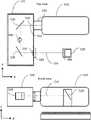
- FIG. 1is an elevational view of a CNC machine with a camera positioned to capture an image of the entire material bed and another camera positioned to capture an image of a portion of the material bed, consistent with some implementations of the current subject matter;
- FIG. 2is a top view of the implementation of the CNC machine shown in FIG. 1 ;
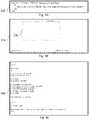
- FIG. 3Ais a diagram illustrating one example of an SVG source file, consistent with some implementations of the current subject matter
- FIG. 3Bis an example of a graphical representation of the cut path in the CNC machine, consistent with some implementations of the current subject matter
- FIG. 3Cis a diagram illustrating the machine file corresponding to the cut path and the source file, consistent with some implementations of the current subject matter
- FIG. 4Ais a diagram illustrating the addition of images, consistent with some implementations of the current subject matter
- FIG. 4Bis a diagram illustrating the subtraction of images, consistent with some implementations of the current subject matter
- FIG. 4Cis a diagram illustrating the differencing of images to isolate a simulated internal lighting effect, consistent with some implementations of the current subject matter
- FIG. 5is a diagram illustrating a sealed optical system, consistent with some implementations of the current subject matter
- FIG. 6is a diagram illustrating optical components acting as a retroreflector, consistent with some implementations of the current subject matter
- FIG. 7is a diagram illustrating a correction mechanism to adjust vertical tilt on a retroreflector, consistent with some implementations of the current subject matter.
- FIG. 8is a diagram illustrating how the center of mass of optical components may be engineered to minimize its differential from the optical axis, consistent with some implementations of the current subject matter.
- cuttingcan generally refer to altering the appearance, properties, and/or state of a material. Cutting can include, for example, making a through-cut, engraving, bleaching, curing, burning, etc. Engraving, when specifically referred to herein, indicates a process by which a CNC machine modifies the appearance of the material without fully penetrating it. For example, in the context of a laser cutter, it can mean removing some of the material from the surface, or discoloring the material e.g. through an application of focused electromagnetic radiation delivering electromagnetic energy as described below.
- laserincludes any electromagnetic radiation or focused or coherent energy source that (in the context of being a cutting tool) uses photons to modify a substrate or cause some change or alteration upon a material impacted by the photons.
- Laserscan be of any desired wavelength, including for example, microwave, lasers, infrared lasers, visible lasers, UV lasers, X-ray lasers, gamma-ray lasers, or the like.
- “cameras”includes, for example, visible light cameras, black and white cameras, IR or UV sensitive cameras, individual brightness sensors such as photodiodes, sensitive photon detectors such as a photomultiplier tube or avalanche photodiodes, detectors of infrared radiation far from the visible spectrum such as microwaves, X-rays, or gamma rays, optically filtered detectors, spectrometers, and other detectors that can include sources providing electromagnetic radiation for illumination to assist with acquisition, for example, flashes, UV lighting, etc.
- individual brightness sensorssuch as photodiodes, sensitive photon detectors such as a photomultiplier tube or avalanche photodiodes, detectors of infrared radiation far from the visible spectrum such as microwaves, X-rays, or gamma rays, optically filtered detectors, spectrometers, and other detectors that can include sources providing electromagnetic radiation for illumination to assist with acquisition, for example, flashes, UV lighting, etc.
- real-time actionsincludes some degree of delay or latency, either programmed intentionally into the actions or as a result of the limitations of machine response and/or data transmission.
- Real-time” actionsare intended to only approximate an instantaneous response, or a response performed as quickly as possible given the limits of the system, and do not imply any specific numeric or functional limitation to response times or the machine actions resulting therefrom.
- the term “material”is the material that is on the bed of the CNC machine.
- the CNC machineis a laser cutter, lathe, or milling machine
- the materialis what is placed in the CNC machine to be cut, for example, the raw materials, stock, or the like.
- the CNC machineis a 3-D printer
- the materialis either the current layer, or previously existent layers or substrate, of an object being crafted by the 3-D printing process.
- the CNC machineis a printer, then the material can be the paper onto which the CNC machine deposits ink.
- a computer numerical controlled (CNC) machineis a machine that is used to add or remove material under the control of a computer.
- headscan incorporate nozzles that spray or release polymers as in a typical 3D printer.
- the headscan include an ink source such as a cartridge or pen.
- materialcan be built up layer by layer until a fully realized 3D object has been created.
- the CNC machinecan scan the surface of a material such as a solid, a liquid, or a powder, with a laser to harden or otherwise change the material properties of said material. New material may be deposited.
- the headscan incorporate tools such as blades on a lathe, drag knives, plasma cutters, water jets, bits for a milling machine, a laser for a laser cutter/engraver, etc.
- FIG. 1is an elevational view of a CNC machine 100 with a camera positioned to capture an image of an entire material bed 150 and another camera positioned to capture an image of a portion of the material bed 150 , consistent with some implementations of the current subject matter.
- FIG. 2is a top view of the implementation of the CNC machine 100 shown in FIG. 1 .
- the CNC machine 100 shown in FIG. 1corresponds to one implementation of a laser cutter. While some features are described in the context of a laser cutter, this is by no means intended to be limiting. Many of the features described below can be implemented with other types of CNC machines.
- the CNC machine 100can be, for example, a lathe, engraver, 3D-printer, milling machine, drill press, saw, etc.
- laser cutter/engraversshare some common features with CNC machines, they have many differences and present particularly challenging design constraints.
- a laser cutter/engraveris subject to regulatory guidelines that restrict the egress of electromagnetic radiation from the unit when operating, making it challenging for light to enter or escape the unit safely, for example to view or record an image of the contents.
- the beam of a laser cutter/engravermust be routed from the emitter to the area to be machined, potentially requiring a series of optical elements such as lenses and mirrors.
- optical elementssuch as lenses and mirrors.
- a variety of optical elements and configurationsmay give rise to the desired size, shape and other considerations of the machining work area, and more broadly CNC machine function.
- the beam of a laser cutter/engraveris easily misdirected, with a small angular deflection of any component relating to the beam path potentially resulting in the beam escaping the intended path, potentially with undesirable consequences.
- a laser beammay be capable of causing material destruction if uncontrolled.
- a laser cutter/engravermay require high voltage and/or radio frequency power supplies to drive the laser itself.
- Liquid coolingis common in laser cutter/engravers to cool the laser, requiring fluid flow considerations.
- Airflowis important in laser cutter/engraver designs, as air may become contaminated with byproducts of the laser's interaction with the material such as smoke, which may in turn damage portions of the machine for example fouling optical systems.
- the air exhausted from the machinemay contain undesirable byproducts such as smoke that must be routed or filtered, and the machine may need to be designed to prevent such byproducts from escaping through an unintended opening, for example by sealing components that may be opened.
- the kerfthe amount of material removed during the operation—is both small and variable depending on the material being processed, the power of the laser, the speed of the laser, and other factors, making it difficult to predict the final size of the object.
- the output of the laser cutter/engraveris very highly dependent on the speed of operation; a momentary slowing can destroy the workpiece by depositing too much laser energy.
- operating parameterssuch as tool rotational speed and volume of material removed are easy to continuously predict, measure, and calculate, while laser cutter/engravers are more sensitive to material and other conditions.
- fluidsare used as coolant and lubricant; in laser cutter/engravers, the cutting mechanism does not require physical contact with the material being affected, and air or other gasses may be used to aid the cutting process in a different manner, by facilitating combustion or clearing debris, for example.
- the CNC machine 100can have a housing surrounding an enclosure or interior area defined by the housing.
- the housingcan include walls, a bottom, and one or more openings to allow access to the CNC machine 100 , etc.
- the CNC machinecan also include an openable barrier as part of the housing to allow access between an exterior of the CNC machine and an interior space of the CNC machine.
- the openable barriercan include, for example, one or more doors, hatches, flaps, and the like that can actuate between an open position and a closed position.
- the openable barriercan attenuate the transmission of light between the interior space and the exterior when in a closed position.
- the openable barriercan be transparent to one or more wavelengths of light or be comprised of portions of varying light attenuation ability.
- One type of openable barriercan be a lid 130 that can be opened or closed to put material 140 on the material bed 150 on the bottom of the enclosure.
- an openable barriercan be a front door that is normally vertical when in the closed position and can open horizontally or vertically to allow additional access.
- the CNC machine 100can execute actions to maintain the safety of the user and the system, for example, a controlled shutdown.
- the CNC machine 100can be completely open (i.e. not having a lid 130 , or walls). Any of the features described herein can also be present in an open configuration, where applicable.
- the CNC machine 100can have one or more movable heads that can be operated to alter the material 140 .
- the movable headcan be the head 160 .
- the head 160can include optical components, mirrors, cameras, and other electronic components used to perform the desired machining operations.
- the head 160typically is a laser-cutting head, but can be a movable head of any type.
- the head 160can be configured to include a combination of optics, electronics, and mechanical systems that can, in response to commands, cause a laser beam or electromagnetic radiation to be delivered to cut or engrave the material 140 .
- the CNC machine 100can also execute operation of a motion plan for causing movement of the movable head. As the movable head moves, the movable head can deliver electromagnetic energy to effect a change in the material 140 that is at least partially contained within the interior space.
- the position and orientation of the optical elements inside the head 160can be varied to adjust the position, angle, or focal point of a laser beam. For example, mirrors can be shifted or rotated, lenses translated, etc.
- the head 160can be mounted on a translation rail 170 that is used to move the head 160 throughout the enclosure.
- the motion of the headcan be linear, for example on an X axis, a Y axis, or a Z axis.
- the headcan combine motions along any combination of directions in a rectilinear, cylindrical, or spherical coordinate system.
- a working area for the CNC machine 100can be defined by the limits within which the movable head can cause delivery of a machining action, or delivery of a machining medium, for example electromagnetic energy.
- the working areacan be inside the interior space defined by the housing. It should be understood that the working area can be a generally three-dimensional volume and not a fixed surface. For example, if the range of travel of a vertically oriented laser cutter is a 10′′ ⁇ 10′′ square entirely over the material bed 150 , and the laser from the laser beam comes out of the laser cutter at a height of 4′′ above the material bed of the CNC machine, that 400 in 2 volume can be considered to be the working area.
- the working areacan be defined by the extents of positions in which material 140 can be worked by the CNC machine 100 , and not necessarily tied or limited by the travel of any one component. For example, if the head 160 could turn at an angle, then the working area could extend in some direction beyond the travel of the head 160 .
- the working areacan also include any surface, or portion thereof, of any material 140 placed in the CNC machine 100 that is at least partially within the working area, if that surface can be worked by the CNC machine 100 .
- oversized materialwhich may extend even outside the CNC machine 100 , only part of the material 140 might be in the working area at any one time.
- the translation rail 170can be any sort of translating mechanism that enables movement of the head 160 in the X-Y direction, for example a single rail with a motor that slides the head 160 along the translation rail 170 , a combination of two rails that move the head 160 , a combination of circular plates and rails, a robotic arm with joints, etc.
- Components of the CNC machine 100can be substantially enclosed in a case or other enclosure.
- the casecan include, for example, windows, apertures, flanges, footings, vents, etc.
- the casecan also contain, for example, a laser, the head 160 , optical turning systems, cameras, the material bed 150 , etc.
- an injection-molding processcan be performed. The injection-molding process can be performed to create a rigid case in a number of designs.
- the injection molding processmay utilize materials with useful properties, such as strengthening additives that enable the injection molded case to retain its shape when heated, or absorptive or reflective elements, coated on the surface or dispersed throughout the material for example, that dissipate or shield the case from laser energy.
- materials with useful propertiessuch as strengthening additives that enable the injection molded case to retain its shape when heated, or absorptive or reflective elements, coated on the surface or dispersed throughout the material for example, that dissipate or shield the case from laser energy.
- one design for the casecan include a horizontal slot in the front of the case and a corresponding horizontal slot in the rear of the case. These slots can allow oversized material to be passed through the CNC machine 100 .
- an interlock systemthat interfaces with, for example, the openable barrier, the lid 130 , door, and the like. Such an interlock is required by many regulatory regimes under many circumstances.
- the interlockcan then detect a state of opening of the openable barrier, for example, whether a lid 130 is open or closed.
- an interlockcan prevent some or all functions of the CNC machine 100 while an openable barrier, for example the lid 130 , is in the open state (e.g. not in a closed state). The reverse can be true as well, meaning that some functions of the CNC machine 100 can be prevented while in a closed state.
- some components of the CNC machine 100can be tied to states of other components of the CNC machine, such as not allowing the lid 130 to open while the laser is on, a movable component moving, a motor running, sensors detecting a certain gas, etc.
- the interlockcan prevent emission of electromagnetic energy from the movable head when detecting that the openable barrier is not in the closed position.
- a traditional CNC machineaccepts a user drawing, acting as a source file that describes the object the user wants to create or the cuts that a user wishes to make.
- source filesare:
- FIG. 3Ais a diagram illustrating one example of an SVG source file 310 , consistent with some implementations of the current subject matter.
- FIG. 3Bis an example of a graphical representation 320 of the cut path 330 in the CNC machine, consistent with some implementations of the current subject matter.
- FIG. 3Cis a diagram illustrating the machine file 340 that would result in a machine creating the cut path 330 , created from the source file 310 , consistent with some implementations of the current subject matter.
- the example source file 310represents a work surface that is 640 ⁇ 480 units with a 300 ⁇ 150 unit rectangle whose top left corner is located 100 units to the right and 100 units down from the top-left corner of the work surface.
- a computer programcan then convert the source file 310 into a machine file 340 that can be interpreted by the CNC machine 100 to take the actions illustrated in FIG. 3B .
- the conversioncan take place on a local computer where the source files reside on the CNC machine 100 , etc.
- the machine file 340describes the idealized motion of the CNC machine 100 to achieve the desired outcome. Take, for example, a 3D printer that deposits a tube-shaped string of plastic material. If the source file specifies a rectangle then the machine file can instruct the CNC machine to move along a snakelike path that forms a filled in rectangle, while extruding plastic.
- the machine filecan omit some information, as well. For example, the height of the rectangle may no longer be directly present in the machine file; the height will be as tall as the plastic tube is high.
- the machine filecan also add some information. For example, the instruction to move the print head from its home position to a corner of the rectangle to begin printing. The instructions can even depart from the directly expressed intent of the user.
- a common setting in 3D printerscauses solid shapes to be rendered as hollow in the machine file to save on material cost.
- the conversion of the source file 310 to the machine file 330can cause the CNC machine to move the cutting tool from (0,0) (in FIG. 3B ) to the point at which cutting is to begin, activate the cutting tool (for example lower a drag knife or energize a laser), trace the rectangle, deactivate the cutting tool, and return to (0,0).
- a motion plan for the CNC machine 100can be generated.
- the motion plancontains the data that determines the actions of components of the CNC machine 100 at different points in time.
- the motion plancan be generated on the CNC machine 100 itself or by another computing system.
- a motion plancan be a stream of data that describes, for example, electrical pulses that indicate exactly how motors should turn, a voltage that indicates the desired output power of a laser, a pulse train that specifies the rotational speed of a mill bit, etc.
- motion plansare defined by the presence of a temporal element, either explicit or inferred, indicating the time or time offset at which each action should occur. This allows for one of the key functions of a motion plan, coordinated motion, wherein multiple actuators coordinate to have a single, pre-planned affect.
- the motion planrenders the abstract, idealized machine file as a practical series of electrical and mechanical tasks.
- a machine filemight include the instruction to “move one inch to the right at a speed of one inch per second, while maintaining a constant number of revolutions per second of a cutting tool.”
- the motion planmust take into consideration that the motors cannot accelerate instantly, and instead must “spin up” at the start of motion and “spin down” at the end of motion.
- the motion planwould then specify pulses (e.g. sent to stepper motors or other apparatus for moving the head or other parts of a CNC machine) occurring slowly at first, then faster, then more slowly again near the end of the motion.
- the machine fileis converted to the motion plan by the motion controller/planner.
- the motion controllercan be a general or special purpose computing device, such as a high performance microcontroller or single board computer coupled to a Digital Signal Processor (DSP).
- DSPDigital Signal Processor
- the job of the motion controlleris to take the vector machine code and convert it into electrical signals that will be used to drive the motors on the CNC machine 100 , taking in to account the exact state of the CNC machine 100 at that moment (e.g. “since the machine is not yet moving, maximum torque must be applied, and the resulting change in speed will be small”) and physical limitations of the machine (e.g. accelerate to such-and-such speed, without generating forces in excess of those allowed by the machine's design).
- the signalscan be step and direction pulses fed to stepper motors or location signals fed to servomotors among other possibilities, which create the motion and actions of the CNC machine 100 , including the operation of elements like actuation of the head 160 , moderation of heating and cooling, and other operations.
- a compressed file of electrical signalscan be decompressed and then directly output to the motors.
- These electrical signalscan include binary instructions similar to l's and 0 's to indicate the electrical power that is applied to each input of each motor over time to effect the desired motion.
- the motion planis the only stage that understands the detailed physics of the CNC machine 100 itself, and translates the idealized machine file into implementable steps. For example, a particular CNC machine 100 might have a heavier head, and require more gradual acceleration. This limitation is modeled in the motion planner and affects the motion plan.
- Each model of CNC machinecan require precise tuning of the motion plan based on its measured attributes (e.g. motor torque) and observed behavior (e.g. belt skips when accelerating too quickly).
- the CNC machine 100can also tune the motion plan on a per-machine basis to account for variations from CNC machine to CNC machine.
- the motion plancan be generated and fed to the output devices in real-time, or nearly so.
- the motion plancan also be pre-computed and written to a file instead of streamed to a CNC machine, and then read back from the file and transmitted to the CNC machine 100 at a later time.
- Transmission of instructions to the CNC machine 100for example, portions of the machine file or motion plan, can be streamed as a whole or in batches from the computing system storing the motion plan. Batches can be stored and managed separately, allowing pre-computation or additional optimization to be performed on only part of the motion plan.
- a file of electrical signalswhich may be compressed to preserve space and decompressed to facilitate use, can be directly output to the motors.
- the electrical signalscan include binary instructions similar to l's and 0 's to indicate actuation of the motor.
- the motion plancan be augmented, either by precomputing in advance or updating in real-time, with the aid of machine vision.
- Machine visionis a general term that describes the use of sensor data, and not only limited to optical data, in order to provide additional input to machine operation.
- Other forms of inputcan include, for example, audio data from an on-board sound sensor such as a microphone, or position/acceleration/vibration data from an on-board sensor such as a gyroscope or accelerometer.
- Machine visioncan be implemented by using cameras to provide images of, for example, the CNC machine 100 , the material being operated on by the CNC machine, the environment of the CNC machine 100 (if there is debris accumulating or smoke present), or any combination of these. These cameras can then route their output to a computer for processing.
- the CNC machine 100By viewing the CNC machine 100 in operation and analyzing the image data it can, for example, be determined if the CNC machine 100 is working correctly, if the CNC machine 100 is performing optimally, the current status of the CNC machine 100 or subcomponents of the CNC machine 100 , etc.
- the materialcan be imaged and, for example, the operation of the CNC machine 100 can be adjusted according to instructions, users can be notified when the project is complete, or information about the material can be determined from the image data. Error conditions can be identified, such as if a foreign body has been inadvertently left in the CNC machine 100 , the material has been inadequately secured, or the material is reacting in an unexpected way during machining.
- Image datarefers to all data gathered from a camera or image sensor, including still images, streams of images, video, audio, metadata such as shutter speed and aperture settings, settings or data from or pertaining to a flash or other auxiliary information, graphic overlays of data superimposed upon the image such as GPS coordinates, in any format, including but not limited to raw sensor data such as a .DNG file, processed image data such as a .JPG file, and data resulting from the analysis of image data processed on the camera unit such as direction and velocity from an optical mouse sensor.
- raw sensor datasuch as a .DNG file
- processed image datasuch as a .JPG file
- data resulting from the analysis of image data processed on the camera unitsuch as direction and velocity from an optical mouse sensor.
- cameras mountedsuch that they gather image data from (also referred to as ‘view’ or ‘image’) an interior portion of the CNC machine 100 .
- the viewingcan occur when the lid 130 is in a closed position or in an open position or independently of the position of the lid 130 .
- one or more camerasfor example a camera mounted to the interior surface of the lid 130 or elsewhere within the case or enclosure, can view the interior portion when the lid 130 to the CNC machine 100 is a closed position.
- the camerascan image the material 140 while the CNC machine 100 is closed and, for example, while machining the material 140 .
- camerascan be mounted within the interior space and opposite the working area.
- Camerascan also be capable of motion such as translation to a plurality of positions, rotation, and/or tilting along one or more axes.
- One or more cameras mounted to a translatable support, such as a gantry 210which can be any mechanical system that can be commanded to move (movement being understood to include rotation) the camera or a mechanism such as a mirror that can redirect the view of the camera, to different locations and view different regions of the CNC machine.
- the head 160is a special case of the translatable support, where the head 160 is limited by the track 220 and the translation rail 170 that constrain its motion.
- Lensescan be chosen for wide angle coverage, for extreme depth of field so that both near and far objects may be in focus, or many other considerations.
- the camerasmay be placed to additionally capture the user so as to document the building process, or placed in a location where the user can move the camera, for example on the underside of the lid 130 where opening the CNC machine 100 causes the camera to point at the user.
- the single camera described abovecan take an image when the lid is not in the closed position.
- Such an imagecan include an object, such as a user, that is outside the CNC machine 100 .
- Camerascan be mounted on movable locations like the head 160 or lid 130 with the intention of using video or multiple still images taken while the camera is moving to assemble a larger image, for example scanning the camera across the material 140 to get an image of the material 140 in its totality so that the analysis of image data may span more than one image.
- a lid camera 110can be mounted to the lid 130 .
- the lid camera 110can be mounted to the underside of the lid 130 .
- the lid camera 110can be a camera with a wide field of view 112 that can image a first portion of the material 140 . This can include a large fraction of the material 140 and the material bed or even all of the material 140 and material bed 150 .
- the lid camera 110can also image the position of the head 160 , if the head 160 is within the field of view of the lid camera 110 . Mounting the lid camera 110 on the underside of the lid 130 allows for the user to be in view when the lid 130 is open.
- a number of sub-imagespossibly acquired at a number of different locations, can be assembled, potentially along with other data like a source file such as an SVG or digitally rendered text, to provide a final image.
- the lid camera 110rotates down with the lid 130 and brings the material 140 into view.
- a head camera 120can be mounted to the head 160 .
- the head camera 120can have a narrower field of view 122 and take higher resolution images of a smaller area, of the material 140 and the material bed, than the lid camera 110 .
- One use of the head camera 120can be to image the cut made in the material 140 .
- the head camera 120can identify the location of the material 140 more precisely than possible with the lid camera 110 .
- Other locations for camerascan include, for example, on an optical system guiding a laser for laser cutting, on the laser itself, inside a housing surrounding the head 160 , underneath or inside of the material bed 150 , in an air filter or associated ducting, etc. Cameras can also be mounted outside the CNC machine 100 to view users or view external features of the CNC machine 100 .
- Multiple camerascan also work in concert to provide a view of an object or material 140 from multiple locations, angles, resolutions, etc.
- the lid camera 110can identify the approximate location of a feature in the CNC machine 100 .
- the CNC machine 100can then instruct the head 160 to move to that location so that the head camera 120 can image the feature in more detail.
- the use of the cameras for machine vision in this applicationis not limited to only that specific type of CNC machine 100 .
- the lid camera 110can be mounted nearby to view the rotating material 140 and the head 160 , and the head camera 120 located near the cutting tool.
- the head camera 120can be mounted on the head 160 that deposits material 140 for forming the desired piece.
- An image recognition programcan identify conditions in the interior portion of the CNC machine 100 from the acquired image data.
- the conditions that can be identifiedare described at length below, but can include positions and properties of the material 140 , the positions of components of the CNC machine 100 , errors in operation, etc.
- instructions for the CNC machine 100can be created or updated.
- the instructionscan, for example, act to counteract or mitigate an undesirable condition identified from the image data.
- the instructionscan include changing the output of the head 160 .
- the lasercan be instructed to reduce or increase power or turn off.
- the updated instructionscan include different parameters for motion plan calculation, or making changes to an existing motion plan, which could change the motion of the head 160 or the gantry 210 .
- the motion plancan be calculated with an equal and opposite offset to counteract the problem, for example for a second subsequent operation or for all future operations.
- the CNC machine 100can execute the instructions to create the motion plan or otherwise effect the changes described above.
- the movable componentcan be the gantry 210 , the head 160 , or an identifiable mark on the head 160 .
- the movable componentfor example the gantry 210 , can have a fixed spatial relationship to the movable head.
- the image datacan update software controlling operation of the CNC machine 100 with a position of the movable head and/or the movable component with their position and/or any higher order derivative thereof.
- multiple camerascan be placed throughout the CNC machine 100 to provide the needed image data. Camera choice and placement can be optimized for many use cases. Cameras closer to the material 140 can be used for detail at the expense of a wide field of view. Multiple cameras may be placed adjacently so that images produced by the multiple cameras can be analyzed by the computer to achieve higher resolution or wider coverage jointly than was possible for any image individually.
- the manipulation and improvement of imagescan include, for example, stitching of images to create a larger image, adding images to increase brightness, differencing images to isolate changes (such as moving objects or changing lighting), multiplying or dividing images, averaging images, rotating images, scaling images, sharpening images, and so on, in any combination.
- the systemmay record additional data to assist in the manipulation and improvement of images, such as recordings from ambient light sensors and location of movable components.
- stitchingcan include taking one or more sub-images from one or more cameras and combining them to form a larger image. Some portions of the images can overlap as a result of the stitching process. Other images may need to be rotated, trimmed, or otherwise manipulated to provide a consistent and seamless larger image as a result of the stitching.
- Lighting artifactssuch as glare, reflection, and the like, can be reduced or eliminated by any of the above methods.
- the image analysis programcan performing edge detection and noise reduction or elimination on the acquired images.
- Edge detectioncan include performing contrast comparisons of different parts of the image to detect edges and identify objects or features in the image.
- Noise reductioncan involve averaging or smoothing of one or more images to reduce the contribution of periodic, random, or pseudo-random image noise, for example that due to CNC machine 100 operation such as vibrating fans, motors, etc.
- FIG. 4Ais a diagram illustrating the addition of images, consistent with some implementations of the current subject matter. Images taken by the cameras can be added, for example, to increase the brightness of an image.
- First image 410has horizontal bands (shown in white against a black background in the figure). The horizontal bands can conform to a more brightly lit object, though the main point is that there is a difference between the bands and the background.
- Second image 412has similar horizontal bands, but offset in the vertical direction relative to those in the first image 410 .
- the first image 410 and second image 412are added, their sum is shown in by the third image 414 .
- the two sets of bandsinterleave to fill in the bright square as shown.
- This techniquecan be applied to, for example, acquiring many image frames from the cameras, possibly in low light conditions, and adding them together to form a brighter image.
- FIG. 4Bis a diagram illustrating the subtraction of images, consistent with some implementations of the current subject matter.
- Image subtractioncan be useful to, for example, isolate dim laser spot from a comparatively bright image.
- a first image 420shows two spots, one representative of a laser spot and the other of an object.
- a second image 422can be taken with the laser off, leaving only the object. Then, the second image 422 can be subtracted from the first image 420 to arrive at the third image 424 .
- the remaining spot in the third image 424is the laser spot.
- FIG. 4Cis a diagram illustrating the differencing of images to isolate a simulated internal lighting effect, consistent with some implementations of the current subject matter.
- an object in the CNC machine 100represented as a circle in first image 430 .
- Thiscould represent, for example an object on the material bed 150 of the CNC machine 100 . If, for example, half of the material bed 150 of the CNC machine 100 was illumined by outside lighting, such as a sunbeam, the second image 420 might appear as shown, with the illuminated side brighter than the side without the illumination. It can sometimes be advantageous to use internal lighting during operation, for example to illuminate a watermark, aid in image diagnostics, or simply to better show a user what is happening in the CNC machine.
- Machine vision processing of imagescan occur at, for example, the CNC machine 100 , on a locally connected computer, or on a remote server connected via the internet.
- image processing capabilitycan be performed by the CNC machine 100 , but with limited speed.
- One example of thiscan be where the onboard processor is slow and can run only simple algorithms in real-time, but which can run more complex analysis given more time. In such a case, the CNC machine 100 could pause for the analysis to be complete, or alternatively, execute the data on a faster connected computing system.
- a specific examplecan be where sophisticated recognition is performed remotely, for example, by a server on the internet. In these cases, limited image processing can be done locally, with more detailed image processing and analysis being done remotely.
- the cameracan use a simple algorithm, run on a processor in the CNC machine 100 , to determine when the lid 130 is closed.
- the processor on the CNC machine 100can send images to a remote server for more detailed processing, for example, to identify the location of the material 140 that was inserted.
- the systemcan also devote dedicated resources to analyzing the images locally, pause other actions, or diverting computing resources away from other activities.
- the head 160can be tracked by onboard, real-time analysis. For example, tracking the position of the head 160 , a task normally performed by optical encoders or other specialized hardware, can be done with high resolution, low resolution, or a combination of both high and low resolution images taken by the cameras. As high-resolution images are captured, they can be transformed into lower resolution images that are smaller in memory size by resizing or cropping. If the images include video or a sequence of still images, some may be eliminated or cropped. A data processor can analyze the smaller images repeatedly, several times a second for example, to detect any gross misalignment.
- the data processorcan halt all operation of the CNC machine 100 while more detailed processing more precisely locates exactly the head 160 using higher resolution images.
- the head 160can be adjusted to recover the correction location.
- imagescan be uploaded to a server where further processing can be performed. The location can be determined by, for example, looking at the head 160 with the lid camera, by looking at what the head camera 120 is currently imaging, etc. For example, the head 160 could be instructed to move to a registration mark. Then the head camera 120 can then image the registration mark to detect any minute misalignment.
- the camerascan be, for example, a single wide-angle camera, multiple cameras, a moving camera where the images are digitally combined, etc.
- the cameras used to image a large region of the interior of the CNC machine 100can be distinct from other cameras that image a more localized area.
- the head camera 160can be one example of a camera that, in some implementations, images a smaller area than the wide-angle cameras.
- a cameraor cameras with broad field of view can cover the whole of the machine interior, or a predefined significant portion thereof.
- the image data acquired from one or more of the camerascan include most (meaning over 50%) of the working area.
- at least 60%, 70%, 80%, 90%, or 100% of the working areacan be included in the image data.
- the above amountsdo not take into account obstruction by the material 140 or any other intervening objects. For example, if a camera is capable of viewing 90% of the working area without material 140 , and a piece of material 140 is placed in the working area, partially obscuring it, the camera is still considered to be providing image data that includes 90% of the working area.
- the image datacan be acquired when the interlock is not preventing the emission of electromagnetic energy.
- a camera mounted outside the machinecan see users and/or material 140 entering or exiting the CNC machine 100 , record the use of the CNC machine 100 for sharing or analysis, or detect safety problems such as an uncontrolled fire.
- Other camerascan provide a more precise look with limited field of view.
- Optical sensors like those used on optical micecan provide very low resolution and few colors, or greyscale, over a very small area with very high pixel density, then quickly process the information to detect material 140 moving relative to the optical sensor. The lower resolution and color depth, plus specialized computing power, allow very quick and precise operation.
- Video camerascan detect changes over time, for example comparing frames to determine the rate at which the camera is moving. Still cameras can be used to capture higher resolution images that can provide greater detail.
- Yet another type of optical scanningcan be to implement a linear optical sensor, such as a flatbed scanner, on an existing rail, like the sliding gantry 210 in a laser system, and then scan it over the material 140 , assembling an image as it scans.
- the lasermay be turned off and on again, and the difference between the two measurements indicates the light scattered from the laser while removing the effect of environmental light.
- the camerascan have fixed or adjustable sensitivity, allowing them to operate in dim or bright conditions. There can be any combination of cameras that are sensitive to different wavelengths. Some cameras, for example, can be sensitive to wavelengths corresponding to a cutting laser, a range-finding laser, a scanning laser, etc. Other cameras can be sensitive to wavelengths that specifically fall outside the wavelength of one or more lasers used in the CNC machine 100 .
- the camerascan be sensitive to visible light only, or can have extended sensitivity into infrared or ultraviolet, for example to view invisible barcodes marked on the surface, discriminate between otherwise identical materials based on IR reflectivity, or view invisible (e.g. infrared) laser beams directly.
- the camerascan even be a single photodiode that measures e.g. the flash of the laser striking the material 140 , or which reacts to light emissions that appear to correlate with an uncontrolled fire.
- the camerascan be used to image, for example, a beam spot on a mirror, light escaping an intended beam path, etc.
- the camerascan also detect scattered light, for example if a user is attempting to cut a reflective material.
- camerascan be implemented, for example, instead of detecting light of the same wavelength of the laser, instead detecting a secondary effect, such as infrared radiation (with a thermographic camera) or x-rays given off by contact between the laser and another material.
- a secondary effectsuch as infrared radiation (with a thermographic camera) or x-rays given off by contact between the laser and another material.
- the camerasmay be coordinated with lighting sources in the CNC machine 100 .
- the lighting sourcescan be positioned anywhere in the CNC machine 100 , for example, on the interior surface of the lid 130 , the walls, the floor, the gantry 210 , etc.
- One example of coordination between the lighting sources and the camerascan be to adjust internal LED illumination while acquiring images of the interior portion with the cameras. For example, if the camera is only capable of capturing images in black and white, the internal LEDs can illuminate sequentially in red, green, and blue, capturing three separate images. The resulting images can then be combined to create a full color RGB image. If external illumination is causing problems with shadows or external lighting effects, the internal lighting can be turned off while a picture is taken, then turned on while a second picture is taken.
- ambient lightcan be cancelled out so that it can be determined what the image looks like when illuminated only by internal lights.
- lightingis movable, for example on the translation arm of the CNC machine 100 , it can be moved around while multiple pictures are taken, then combined, to achieve an image with more even lighting.
- the brightness of the internal lightscan also be varied like the flash in a traditional camera to assist with illumination.
- the lightingcan be moved to a location where it better illuminates an area of interest, for example so it shines straight down a slot formed by a cut, so a camera can see the bottom of the cut. If the internal lighting is interfering, it can be turned off while the camera takes an image.
- the lightingcan be turned off for such a brief period that the viewer does not notice (e.g. for less than a second, less than 1/60 th of a second, or less than 1/120 th of a second).
- the internal lightingmay be momentarily brightened like a camera flash to capture a picture. Specialized lights may be used and/or engaged only when needed; for example, an invisible but UV-fluorescent ink might be present on the material. When scanning for a barcode, UV illumination might be briefly flashed while a picture is captured so that any ink present would be illuminated.
- the same technique of altering the lighting conditionscan be performed by toggling the range-finding and/or cutting lasers as well, to isolate their signature and/or effects when imaging.
- the imagescan be cropped, translated, expanded, rotated, and so on, to obtain images that share common features in order to allow subtraction.
- This differencing techniqueis preferably done with automatic adjustments in the cameras are overridden or disabled. For example, disabling autofocus, flashes, etc.
- Features that can ideally be held constant between imagescan include, for example, aperture, shutter speed, white balance, etc. In this way, the changes in the two images are due only to differences from the lighting and not due to adjustment in the optical system.
- Multiple camerasor a single camera moved to different locations in the CNC machine 100 , can provide images from different angles to generate 3D representations of the surface of the material 140 or an object.
- the 3D representationscan be used for generating 3D models, for measuring the depth that an engraving or laser operation produced, or providing feedback to the CNC machine 100 or a user during the manufacturing process. It can also be used for scanning, to build a model of the material 140 for replication.
- the cameracan be used to record photos and video that the user can use to share their progress.
- Automatic “making of” sequencescan be created that stitch together various still and video images along with additional sound and imagery, for example the digital rendering of the source file or the user's picture from a social network.
- Knowledge of the motion plan, or even the control of the cameras via the motion plan directly,can enable a variety of optimizations.
- the final videocan be created with footage from the head camera at any time that the gantry is directed to a location that is known to obscure the lid camera.
- the camerascan be instructed to reduce their aperture size, reducing the amount of light let in, when the machine's internal lights are activated.
- the machineis a laser cutter/engraver and activating the laser causes a camera located in the head to become overloaded and useless, footage from that camera may be discarded when it is unavailable.
- elements of the motion planmay be coordinated with the camera recording for optimal visual or audio effect, for example fading up the interior lights before the cut or driving the motors in a coordinated fashion to sweep the head camera across the material for a final view of the work result.
- sensor data collected by the systemmight be used to select camera images; for example, a still photo of the user might be captured from a camera mounted in the lid when an accelerometer, gyroscope, or other sensor in the lid detects that the lid has been opened and it has reached the optimal angle.
- recording of videomight cease if an error condition is detected, such as the lid being opened unexpectedly during a machining operation.
- the videocan be automatically edited using information like the total duration of the cut file to eliminate or speed up monotonous events; for example, if the laser must make 400 holes, then that section of the cut plan could be shown at high speed. Traditionally, these decisions must all be made by reviewing the final footage, with little or no a priori knowledge of what they contain.
- Pre-selecting the footagecan allow higher quality video and much less time spent editing it.
- Video and images from the production processcan be automatically stitched together in a variety of fashions, including stop motion with images, interleaving video with stills, and combining video and photography with computer-generated imagery, e.g. a 3D or 2D model of the item being rendered.
- Videocan also be enhanced with media from other sources, such as pictures taken with the user's camera of the final product.
- FIG. 5is a diagram illustrating a sealed optical system 510 , consistent with some implementations of the current subject matter.
- the top portion of FIG. 5illustrates a top view and the bottom portion of FIG. 5 illustrates a bottom view where the laser beam is directed down from the head to the material.
- the sealed optical system 510can be combined with the laser 515 to result in a closed system where one or more of the turning mirrors or laser optics are prevented from being exposed to outside (or otherwise contaminated) air, with the possible exception of the outermost optic, which can be a flat aperture acting as a window that can be easily accessed and cleaned.
- the outermost opticcould also be a lens.
- implementationsdescribe two turning mirrors in a sealed optical system
- other implementationscan include any number of turning mirrors, lenses, or other optical components fixed in non-adjustable positions.
- Such implementationscan be in a sealed optical system, but can also be in an optical system that is not sealed from the remainder of the CNC machine interior volume.
- the non-adjustable optical componentscan be not enclosed by anything other than the CNC machine housing.
- the sealed optical system 510can include an entry aperture 540 , a housing, two turning mirrors 530 oriented at a fixed angle to each other which in one implementation is 90°, and a window attached to an exit aperture 580 .
- the sealed optical system 510can also include one or more pivots 560 , possibly on different axes, to allow the sealed optical system 510 to rotate, thus changing the angle of the fixed turning mirrors 530 relative to an incoming laser beam 512 from the laser 515 .
- the mirrorscan also be mounted so that they are independently adjustable within the sealed optical system 510 .
- the angle of the sealed optical system 510by adjusting the angle of the sealed optical system 510 , the separation of the incoming laser beam 512 and an outgoing laser beam 516 to the head 160 can be adjusted without affecting the angle of the outgoing laser beam 516 , as would occur if a single mirror 530 was adjusted independently. Because in this example the turning mirrors 530 are oriented to always result in a 180 degree turn regardless of the angle of the sealed optical system 510 , rotating the sealed optical system 510 only translates the outgoing laser beam 516 while retaining parallelism between the incoming laser beam 512 and the outgoing laser beam 516 . Such a translation can be adjusted to align the laser beam to optical elements in the head 160 .
- a strategy for minimizing laser beam alignment errorsmay involve engineering or optimizing the system such that the beam path is as short as possible. Reducing the length of the beam path may achieve benefits including better overall alignment of the optical system, due to the corresponding reduction in (even small) error propagation over shorter distances.
- a laser tube 570 and its associated beam pathmay be housed or affixed directly to the moving rail of the CNC machine, and moved in tandem.
- one implementation for increasing the rigidity of a mirror's positionmay involve the use of at least one fixture designed for this purpose; one such example may include a fixture that a mirror slides into and is held in a fixed place, for example by a spring.
- an adjustable fixturemay be used, but the adjustment mechanisms are permanently fixed at the factory, preventing both drift due to mechanical stress and user-initiated adjustments.
- FIG. 6is a diagram illustrating optical components acting as a retroreflector, consistent with some implementations of the current subject matter.
- Another non-encompassing exampleinvolves the exit aperture from the laser tube 570 ; in the present implementation, the beam is engineered to exit in parallel, however location of the exit aperture may vary due to manufacturing variations, (e.g., laser tube defects). This is illustrated in the top portion of FIG. 6 , by the multiple possible beam paths that could result from a misalignment.
- the angle of the laser tube 570may be the subject of angular corrections, for example via the use of spacers or other such fittings that serve to maintain parallelism of the beam and the rail. These spacers can adjust offsets or angular displacements of the laser 515 or other optical components.
- the spacerscan pivot, as shown in FIG. 6 other implementations, the spacers can be linearly offset to position the laser at a particular angle.
- the right pair set of spacerscan be offset in the +Y direction from the left pair of spacers. This would give the laser 515 an angular tilt resulting in the laser housing having an angle going down and to the left.
- Such an adjustmentcan be implemented to correct for a laser tube or lens that was causing the laser 515 to have an undesired angle up and to the left, when exiting the laser housing.
- FIG. 7is a diagram illustrating a correction mechanism to adjust vertical tilt on a retroreflector, consistent with some implementations of the current subject matter.
- there can be a two-mirror retroreflectorguaranteeing that the beam comes out parallel to the incoming beam in the X plane. However, it can still tilt up and down in the Y plane.
- the mirrorscan be mounted on a folded bracket that is manufactured to an incorrect angle, and includes a screw 710 that can be used to drive the bracket to the correct angle.
- the bracketcan be driven to the correct angle at the factory, and the screw may be locked in place with adhesive.
- three mirrorsmay be arranged as in the corner of a cube. In this case, the exiting laser beam is guaranteed to be parallel to the incoming laser beam both horizontally and vertically, and this adjustment is not required.
- the windowscan be any sort of removable optical window suitable for the transmission of laser light from the sealed optical system 510 to the head 160 .
- the laser light wavelengthcan be 10.6 microns emitted from a carbon dioxide laser
- the windowcan be Zinc Selenide (ZnSe).
- the windowscan act to substantially seal the sealed optical system 510 against air which can contain dust, smoke, or other contaminants that can coat any of the other optical elements in the sealed optical system 510 or in the laser 515 .
- pressurized aircan be introduced by means of a fan or a compressed air line, preventing contaminants from entering by maintaining positive pressure in the enclosure.
- the exit aperture 550can simply be extended, optionally with baffles, to prevent contaminants from migrating into the sealed optical system 510 .
- Other techniquescan be used to reduce or eliminate contamination of the output window including, the direction of clean air at the window, the design of airflow in the system so that dirty air is not directly routed at the window, and other measures.
- the turning mirrorscan be mounted at the fixed angle, for example, by adding one or more spacers until a correct angle is achieved.
- the turning mirrors mounted at the fixed anglethey cannot be adjusted to change the fixed angle after being mounted.
- the mirrorcan be mounted in a particular position or orientation during the manufacturing or assembly process, but thereafter, it cannot be adjusted without removing or damaging the turning mirror or the mounting holding the turning mirror.
- each of the turning mirrorscannot be adjusted to change the fixed angle after the mounting of each of the turning mirrors.
- a turning mirrorcan be in a mount formed from the housing of the computer numerically controlled machine.
- the turning mirrorcan be in a removable mount fixedly attached to the computer numerically controlled machine and is not adjustable to change the fixed angle.
- a turning mirrorcan be placed into a mount that can be attached to the CNC machine with fasteners, magnetic retainers, compression fittings, or the like. The mount and turning mirror can be removed from the CNC machine, but when fully and properly mounted, can have an orientation and position that only results in the fixed angle.
- the sealed optical systemcontains a pivot that allows the sealed optical system to rotate about the pivot.
- the relative orientation of the turning mirrors in the sealed optical systemdoes not change as the angle between the turning mirrors can remain fixed.
- one or more of the turning mirrorscan be at a fixed angle relative to some, but not necessarily all, of the other turning mirrors or optical elements.
- the laser headcan move horizontally relative to the turning mirror closest to it. This horizontal movement does not change the fixed angle between a coplanar turning mirror in the laser head (not shown, but for example used to direct the laser beam downward). However, this horizontal movement can change the angle with the other turning mirror because the horizontal movement is not on the line directly connecting the two mirrors.
- the turning mirrorscan be fixed at an angle relative to only one adjacent turning mirror.
- the turning mirrorscan be fixed at an angle relative to all adjacent optical elements that provide or receive light to or from the particular turning mirror.
- an adjustment mechanismconfigured to adjust a position or an orientation of the plurality of optical elements simultaneously without changing the fixed angle.
- the adjustment mechanismcan include a pivot located at a center of the optical elements and the optical elements are configured to act as a retroreflector.
- the optical componentscan be affixed in the computer numerically controlled machine that is not adjustable to change an angle or a position of the plurality of optical components after affixing.
- the affixingcan include at least one of welding, screwing, bolting, and gluing.
- this conceptextends to engineering the CNC machine's optical components so that the mechanical axis is coincidental with the optical axis. In some cases, this may be achieved by altering the center of mass of optical system components to prevent asymmetric distribution of stress on the overall system that may be caused over time by normal machine vibration. If the center of mass is not directly over the optical axis, the system will pivot around the center of mass, resulting in an asymmetric flexing. The amount of flex (i.e., the moment of inertia around that axis) will be proportional to the differential between the center of mass and the optical axis; if that difference is negligible, then the moment of inertia is effectively zero.
- FIG. 8illustrates this concept using the example of a first mirror mount 810 , which has a different center of mass than the optical system 510 .
- This differential in the center of mass between the first mirror mount 810 and the optical system 510may cause mechanical stress on the optical system 510 , for instance, as one side of the first mirror mount 810 pivots about its center of mass and rotates downward over time, thereby causing beam misalignment.
- the mirrors 530may still operation as a retroflector, but the optical system 510 will no longer be correctly aligned.
- FIG. 8further illustrates an example of an engineering strategy for maintaining the alignment of the optical system 510 .
- the alignment of the optical system 510may be maintained by redistributing the weight of a second mirror mount 820 such that the center of mass of the second mirror mount 820 is aligned with that of the optical system 510 .
- Thismay be achieved by a variety of strategies including, for example, machining the second mirror mount 820 in a manner that reduces the overall weight of the second mirror mount 820 is reduced.
- the second mirror mount 820may include strategic cutouts that reduce the overall weight of the second mirror mount 820 .
- the second mirror mount 820may be machined to achieve a desired center of mass, for example, which aligns with that of the optical system 510 .
- an auto-alert systemmay be used to automatically detect system failures over time.
- a system that measures the height of internal componentssuch as by taking absolute or relative measurements with respect to other components
- monitors for values within accepted boundsis one such strategy that may be employed to flag to users when routine servicing or maintained may be needed.
- sensorsmay be used to determine the positioning of the end-plate either with respect to known parameters (e.g. the distance from the machine bed determined by height sensors, or whether the end-plate is parallel by leveling sensors).
- the use of flexible or less-rigid fixtures that resist deforming under mechanical stressmay be used.
- the mirror mountmay be composed, in whole or in part, of an elastic mount structure.
- the use of hinge joints or other mechanisms that reduce the strain on the plate itselfmay be employed for such a purpose.
- the use of strategically-placed cut-outs on the mirror-plate itselfmay be engineered such that any distribution of stress acts in a symmetrical way on such fixtures.
- a systemcan include a head of a computer numerically controlled machine configured to deliver electromagnetic energy sufficient to cause a change in a material at least partially contained within an interior space of the computer numerically controlled machine.
- the systemcan further include an optical system comprising a plurality of optical elements in the computer numerically controlled machine, the plurality of optical elements oriented at a fixed angle to each other to deliver the electromagnetic energy from the head to the material.
- the plurality of optical elementscan include at least one of a mirror and a lens. At least one of the plurality of optical elements can be mounted at the fixed angle and cannot be adjusted to change the fixed angle after the mounting. Each of the plurality of optical elements cannot be adjusted to change the fixed angle after the mounting of each of the plurality of optical elements. The at least one of the plurality of optical elements can be mounted at the fixed angle at least by adding one or more spacers until a correct angle is achieved. The least one of the plurality of optical elements can be in a mount formed from the housing of the computer numerically controlled machine.
- the systemmay further include an adjustment mechanism configured to adjust a position or an orientation of the plurality of optical elements simultaneously without changing the fixed angle.
- the adjustment mechanismcan include a pivot located at a center of the plurality of optical elements, wherein the plurality of optical elements are configured to act as a retroreflector.
- the plurality of optical componentscan be affixed in the computer numerically controlled machine such that an angle or a position of the plurality of optical components cannot be adjusted after the affixing.
- the affixingcan include at least one of welding, screwing, bolting, and gluing.
- the headcan be coupled with a moving rail of the computer numerically controlled machine.
- the head and the moving railcan be configured to move in tandem in order to minimize a path of the electromagnetic energy.
- the optical systemcan be associated with a first center of mass.
- the plurality of optical elementscan be associated with a second center of mass.
- the first center of masscan be aligned with the second center of mass.
- a weight of at least one of the plurality of optical elementscan be reduced in order to align the first center of mass with the second center of mass.
- the weight of the at least one of the plurality of optical elementscan be reduced by at least reducing a weight of a mount housing the at least one of the plurality of optical elements.
- the weight of the mountcan be reduced by machining the mount to include one or more cutouts.
- At least one of the plurality of optical elementscan be housed in an elastic mount configured to reduce mechanical stress against the optical system.
- One or more aspects or features of the subject matter described hereincan be realized in digital electronic circuitry, integrated circuitry, specially designed application specific integrated circuits (ASICs), field programmable gate arrays (FPGAs) computer hardware, firmware, software, and/or combinations thereof.
- ASICsapplication specific integrated circuits
- FPGAsfield programmable gate arrays
- These various aspects or featurescan include implementation in one or more computer programs that are executable and/or interpretable on a programmable system including at least one programmable processor, which can be special or general purpose, coupled to receive data and instructions from, and to transmit data and instructions to, a storage system, at least one input device, and at least one output device.
- the programmable system or computing systemmay include clients and servers.
- a client and serverare generally remote from each other and typically interact through a communication network. The relationship of client and server arises by virtue of computer programs running on the respective computers and having a client-server relationship to each other.
- machine-readable signalrefers to any signal used to provide machine instructions and/or data to a programmable processor.
- the machine-readable mediumcan store such machine instructions non-transitorily, such as for example as would a non-transient solid-state memory or a magnetic hard drive or any equivalent storage medium.
- the machine-readable mediumcan alternatively or additionally store such machine instructions in a transient manner, such as for example as would a processor cache or other random access memory associated with one or more physical processor cores.
- one or more aspects or features of the subject matter described hereincan be implemented on a computer having a display device, such as for example a cathode ray tube (CRT) or a liquid crystal display (LCD) or a light emitting diode (LED) monitor for displaying information to the user and a keyboard and a pointing device, such as for example a mouse or a trackball, by which the user may provide input to the computer.
- a display devicesuch as for example a cathode ray tube (CRT) or a liquid crystal display (LCD) or a light emitting diode (LED) monitor for displaying information to the user
- LCDliquid crystal display
- LEDlight emitting diode
- a keyboard and a pointing devicesuch as for example a mouse or a trackball
- feedback provided to the usercan be any form of sensory feedback, such as for example visual feedback, auditory feedback, or tactile feedback; and input from the user may be received in any form, including, but not limited to, acoustic, speech, or tactile input.
- Other possible input devicesinclude, but are not limited to, touch screens or other touch-sensitive devices such as single or multi-point resistive or capacitive trackpads, voice recognition hardware and software, optical scanners, optical pointers, digital image capture devices and associated interpretation software, and the like.
- phrases such as “at least one of” or “one or more of”may occur followed by a conjunctive list of elements or features.
- the term “and/or”may also occur in a list of two or more elements or features. Unless otherwise implicitly or explicitly contradicted by the context in which it used, such a phrase is intended to mean any of the listed elements or features individually or any of the recited elements or features in combination with any of the other recited elements or features.
- the phrases “at least one of A and B;” “one or more of A and B;” and “A and/or B”are each intended to mean “A alone, B alone, or A and B together.”
- a similar interpretationis also intended for lists including three or more items.
- the phrases “at least one of A, B, and C;” “one or more of A, B, and C;” and “A, B, and/or C”are each intended to mean “A alone, B alone, C alone, A and B together, A and C together, B and C together, or A and B and C together.”
- Use of the term “based on,” above and in the claimsis intended to mean, “based at least in part on,” such that an unrecited feature or element is also permissible.
Landscapes
- Physics & Mathematics (AREA)
- Optics & Photonics (AREA)
- Engineering & Computer Science (AREA)
- Mechanical Engineering (AREA)
- Plasma & Fusion (AREA)
- Laser Beam Processing (AREA)
Abstract
Description
Claims (13)
Priority Applications (3)
| Application Number | Priority Date | Filing Date | Title |
|---|---|---|---|
| US15/823,512US11305379B2 (en) | 2016-11-25 | 2017-11-27 | Preset optical components in a computer numerically controlled machine |
| US17/720,400US20220339735A1 (en) | 2016-11-25 | 2022-04-14 | Preset optical components in a computer numerically controlled machine |
| US17/903,034US12420355B2 (en) | 2016-11-25 | 2022-09-05 | Laser fabrication with beam detection |
Applications Claiming Priority (2)
| Application Number | Priority Date | Filing Date | Title |
|---|---|---|---|
| US201662426438P | 2016-11-25 | 2016-11-25 | |
| US15/823,512US11305379B2 (en) | 2016-11-25 | 2017-11-27 | Preset optical components in a computer numerically controlled machine |
Related Parent Applications (1)
| Application Number | Title | Priority Date | Filing Date |
|---|---|---|---|
| US17/699,386Continuation-In-PartUS20220350306A1 (en) | 2016-11-25 | 2022-03-21 | Controlled Deceleration of Moveable Components in a Computer Numerically Controlled Machine |
Related Child Applications (2)
| Application Number | Title | Priority Date | Filing Date |
|---|---|---|---|
| US17/720,400ContinuationUS20220339735A1 (en) | 2016-11-25 | 2022-04-14 | Preset optical components in a computer numerically controlled machine |
| US17/720,400Continuation-In-PartUS20220339735A1 (en) | 2016-11-25 | 2022-04-14 | Preset optical components in a computer numerically controlled machine |
Publications (2)
| Publication Number | Publication Date |
|---|---|
| US20180147659A1 US20180147659A1 (en) | 2018-05-31 |
| US11305379B2true US11305379B2 (en) | 2022-04-19 |
Family
ID=60703103
Family Applications (2)
| Application Number | Title | Priority Date | Filing Date |
|---|---|---|---|
| US15/823,512Active2039-05-27US11305379B2 (en) | 2016-11-25 | 2017-11-27 | Preset optical components in a computer numerically controlled machine |
| US17/720,400PendingUS20220339735A1 (en) | 2016-11-25 | 2022-04-14 | Preset optical components in a computer numerically controlled machine |
Family Applications After (1)
| Application Number | Title | Priority Date | Filing Date |
|---|---|---|---|
| US17/720,400PendingUS20220339735A1 (en) | 2016-11-25 | 2022-04-14 | Preset optical components in a computer numerically controlled machine |
Country Status (2)
| Country | Link |
|---|---|
| US (2) | US11305379B2 (en) |
| WO (1) | WO2018098398A1 (en) |
Families Citing this family (16)
| Publication number | Priority date | Publication date | Assignee | Title |
|---|---|---|---|---|
| EP3907570A1 (en)* | 2015-02-12 | 2021-11-10 | Glowforge Inc. | Cloud controlled laser fabrication |
| KR20170087610A (en)* | 2016-01-21 | 2017-07-31 | 삼성전자주식회사 | Apparatus for cutting a wafer |
| US12420355B2 (en) | 2016-11-25 | 2025-09-23 | Glowforge Inc. | Laser fabrication with beam detection |
| WO2018098399A1 (en) | 2016-11-25 | 2018-05-31 | Glowforge Inc. | Controlled deceleration of moveable components in a computer numerically controlled machine |
| WO2018098396A1 (en) | 2016-11-25 | 2018-05-31 | Glowforge Inc. | Multi-user computer-numerically-controlled machine |
| WO2018098393A1 (en) | 2016-11-25 | 2018-05-31 | Glowforge Inc. | Housing for computer-numerically-controlled machine |
| WO2018098397A1 (en) | 2016-11-25 | 2018-05-31 | Glowforge Inc. | Calibration of computer-numerically-controlled machine |
| WO2018098395A1 (en) | 2016-11-25 | 2018-05-31 | Glowforge Inc. | Improved engraving in a computer numerically controlled machine |
| CN110226137A (en) | 2016-11-25 | 2019-09-10 | 格罗弗治公司 | It is manufactured by image trace |
| DE102019201723A1 (en)* | 2019-02-11 | 2020-08-13 | Trumpf Laser- Und Systemtechnik Gmbh | Method for setting up a machine tool and manufacturing system |
| CN111958319A (en)* | 2020-08-17 | 2020-11-20 | 枣庄科技职业学院 | Spatial positioning measuring device and method for three-dimensional numerical control machine tool |
| US11740608B2 (en) | 2020-12-24 | 2023-08-29 | Glowforge, Inc | Computer numerically controlled fabrication using projected information |
| US11698622B2 (en) | 2021-03-09 | 2023-07-11 | Glowforge Inc. | Previews for computer numerically controlled fabrication |
| CN215658430U (en)* | 2021-09-24 | 2022-01-28 | 宁德时代新能源科技股份有限公司 | Welding device and welding equipment |
| AT525468B1 (en) | 2021-09-30 | 2023-10-15 | Trotec Laser Gmbh | Method for determining a position of a workpiece in a processing space of a laser plotter for cutting, engraving, marking and/or labeling the workpiece, as well as methods for calibrating and laser plotters therefor |
| US20230241720A1 (en)* | 2022-01-31 | 2023-08-03 | Standex International Corporation | Techniques for closed-loop control of a laser-engraving process |
Citations (248)
| Publication number | Priority date | Publication date | Assignee | Title |
|---|---|---|---|---|
| US3721811A (en) | 1971-04-29 | 1973-03-20 | Cincinnati Milacron Inc | Apparatus for commanding a deceleration in numerical control systems |
| US3967176A (en) | 1974-10-15 | 1976-06-29 | Westinghouse Electric Corporation | Process control apparatus |
| US4055787A (en)* | 1975-07-28 | 1977-10-25 | Giddings & Lewis, Inc. | Interruptable numerical contouring control system with return to path safeguards |
| US4138718A (en) | 1977-11-14 | 1979-02-06 | Allen-Bradley Company | Numerical control system with downloading capability |
| EP0050425A2 (en) | 1980-09-29 | 1982-04-28 | Xerox Corporation | A method of replacing a laser |
| US4383762A (en)* | 1980-02-14 | 1983-05-17 | Kayser-Threde Gmbh | Two-beam interferometer for Fourier spectroscopy with rigid pendulum |
| US4518843A (en)* | 1982-09-01 | 1985-05-21 | Westinghouse Electric Corp. | Laser lens and light assembly |
| US4589729A (en)* | 1982-01-12 | 1986-05-20 | At&T Bell Laboratories | Apparatus comprising an articulated arm radiation guide |
| US4650287A (en) | 1984-07-23 | 1987-03-17 | Showa Denko Kabushiki Kaisha | Laser-light shield and method for shielding human body from laser light |
| US4723219A (en) | 1985-06-21 | 1988-02-02 | Amca International Corporation | Programmed path for automatic tool retraction and return responsive to degradation threshold |
| US4863538A (en)* | 1986-10-17 | 1989-09-05 | Board Of Regents, The University Of Texas System | Method and apparatus for producing parts by selective sintering |
| US4894831A (en)* | 1988-09-07 | 1990-01-16 | Spectra-Physics | Longitudinally pumped laser oscillator |
| US4901359A (en) | 1985-12-14 | 1990-02-13 | Durkopp System Technik Gmbh | Method and apparatus for automatically cutting material in standard patterns |
| US4918611A (en) | 1988-07-21 | 1990-04-17 | Industrial Technology Research Institute | Method and apparatus for controlling laser cutting by image processing |
| US4998260A (en)* | 1989-07-05 | 1991-03-05 | Think Laboratory Co., Ltd. | Method for correcting the path of a gas laser beam |
| JPH03254380A (en) | 1990-02-28 | 1991-11-13 | Matsushita Electric Ind Co Ltd | Numerical control device for laser processing machines |
| JPH04244347A (en) | 1991-01-29 | 1992-09-01 | Osaka Kiko Co Ltd | Life tool change method during machining |
| JPH05205051A (en) | 1992-01-23 | 1993-08-13 | Toyota Motor Corp | Optical shape recognition device |
| WO1994003302A1 (en) | 1992-08-03 | 1994-02-17 | Fanuc Ltd | Photo-scanning type laser machine |
| US5298843A (en) | 1991-01-21 | 1994-03-29 | Fanuc Ltd. | Method for restarting punch press machine and numerical controller |
| JPH06196557A (en) | 1992-12-24 | 1994-07-15 | Sumitomo Electric Ind Ltd | Method and device for dicing semiconductor wafer |
| US5355250A (en) | 1991-03-29 | 1994-10-11 | Pirelli Cavi S.P.A. | Fiber optical communication line with shut off control |
| US5396279A (en) | 1991-12-06 | 1995-03-07 | Meurer Nonfood Product Gmbh | Method and apparatus for setting flat elements in relation to a reference device, in particular stamping dies or the like |
| US5475521A (en) | 1992-05-09 | 1995-12-12 | Alcatel Sel Aktiengesellschaft | Optical communication system with monitoring device for avoiding giant pluses |
| WO1996023240A1 (en) | 1995-01-27 | 1996-08-01 | Fraunhofer-Gesellschaft zur Förderung der angewandten Forschung e.V. | Process and device for imaging an object |
| US5585018A (en) | 1994-02-24 | 1996-12-17 | Mitsubishi Denki Kabushiki Kaisha | Laser cutting method eliminating defects in regions where cutting conditions are changed |
| US5682319A (en) | 1991-06-04 | 1997-10-28 | Anca Pty. Ltd. | Computer numerically controlled machines |
| FR2748562A1 (en) | 1996-05-10 | 1997-11-14 | Sofie Instr | METHOD AND DEVICE WITH TWO OBSERVATION CAMERAS FOR THREE-DIMENSIONAL MEASUREMENTS OF A COMPLEX STRUCTURE |
| US5756961A (en) | 1993-09-27 | 1998-05-26 | Mitsubishi Denki Kabushiki Kaisha | Laser cutting machine |
| EP0954125A2 (en) | 1998-04-28 | 1999-11-03 | Lucent Technologies Inc. | A method and apparatus for controlling optical signal power in response to faults in an optical fiber path |
| US6031200A (en) | 1997-08-04 | 2000-02-29 | Data Technology, Inc. | In-process kerf measurement system |
| US6085122A (en) | 1997-05-30 | 2000-07-04 | Dtm Corporation | End-of-vector laser power control in a selective laser sintering system |
| US6087625A (en)* | 1997-03-21 | 2000-07-11 | Sumitomo Heavy Industries, Ltd. | Laser machining apparatus |
| US20010012973A1 (en) | 1999-12-16 | 2001-08-09 | Peter Wehrli | Method and device for disturbance sensing, especially collision sensing, in the drive system of a numerically controlled machine tool |
| US6284999B1 (en)* | 1999-07-23 | 2001-09-04 | Lillbacka Jetair Oy | Laser cutting system |
| WO2001076250A1 (en) | 2000-04-04 | 2001-10-11 | Learningaction, Inc. | Streaming multimedia information |
| JP2001330413A (en) | 2000-05-22 | 2001-11-30 | Disco Abrasive Syst Ltd | Thickness measuring method and thickness measuring device |
| US6326586B1 (en)* | 1999-07-23 | 2001-12-04 | Lillbacka Jetair Oy | Laser cutting system |
| JP2002123306A (en) | 2000-10-17 | 2002-04-26 | Toshiba Mach Co Ltd | Monitor system for machine tool |
| US6420675B1 (en)* | 1999-10-08 | 2002-07-16 | Nanovia, Lp | Control system for ablating high-density array of vias or indentation in surface of object |
| US6420674B1 (en) | 1999-04-30 | 2002-07-16 | W. A. Whitney Co. | Heavy-duty laser plate cutting machine |
| US20020129485A1 (en) | 2001-03-13 | 2002-09-19 | Milling Systems And Concepts Pte Ltd | Method and apparatus for producing a prototype |
| US20020144987A1 (en)* | 2001-04-06 | 2002-10-10 | W.A. Whitney Co. | Cube corner laser beam retroreflector apparatus for a laser equipped machine tool |
| US6483596B1 (en)* | 1999-04-23 | 2002-11-19 | Eos Gmbh Electro Optical Systems | Method of calibrating an apparatus for producing a three-dimensional object, calibration apparatus and method and apparatus for producing a three-dimensional object |
| US6498653B1 (en)* | 1998-12-14 | 2002-12-24 | Optodyne, Inc. | Tool path measurement |
| US6528758B2 (en)* | 2001-02-12 | 2003-03-04 | Icon Laser Technologies, Inc. | Method and apparatus for fading a dyed textile material |
| US20030049373A1 (en) | 2001-09-13 | 2003-03-13 | Van De Rijdt Johannes Hubertus Antonius | Apparatus for and method of applying a substance to a substrate |
| EP1309108A1 (en) | 2001-10-31 | 2003-05-07 | Agilent Technologies, Inc. (a Delaware corporation) | Optical transceiver with automatic power shut-down arrangement |
| US6609044B1 (en) | 1996-09-30 | 2003-08-19 | Cincinnati Incorporated | Method and apparatus for a cutting system for avoiding pre-cut features |
| US6628322B1 (en) | 1998-08-07 | 2003-09-30 | Brown & Sharpe Dea, S.P.A. | Device and method for positioning a measuring head on a noncontact three-dimensional measuring machine |
| US20040029493A1 (en) | 2002-08-06 | 2004-02-12 | Marc Tricard | Uniform thin films produced by magnetorheological finishing |
| US6696667B1 (en)* | 2002-11-22 | 2004-02-24 | Scimed Life Systems, Inc. | Laser stent cutting |
| US20040060910A1 (en) | 2002-05-17 | 2004-04-01 | Rainer Schramm | High speed, laser-based marking method and system for producing machine readable marks on workpieces and semiconductor devices with reduced subsurface damage produced thereby |
| US20040207831A1 (en) | 2003-04-15 | 2004-10-21 | Honda Motor Co., Ltd. | Ranging apparatus, ranging method, and ranging program |
| US20040223165A1 (en) | 2003-03-14 | 2004-11-11 | Omron Corporation | Optical film measuring device |
| US20040245227A1 (en)* | 2001-07-26 | 2004-12-09 | Clive Grafton-Reed | System and method for delivering an energy beam to selected impinge points on a work piece |
| US20050051523A1 (en)* | 2003-09-09 | 2005-03-10 | W.A. Whitney Co. | Laser machine tool with image sensor for registration of workhead guidance system |
| US20050069682A1 (en) | 2003-09-30 | 2005-03-31 | Tan Tseng | Custom 3-D Milled Object with Vacuum-Molded 2-D Printout Created from a 3-D Camera |
| US20050071020A1 (en) | 2000-12-06 | 2005-03-31 | Tsunehiko Yamazaki | Numerically controlled method |
| US20050115941A1 (en) | 2002-07-31 | 2005-06-02 | Sukhman Yefim P. | Laser containment structure allowing the use of plastics |
| US20050142701A1 (en) | 2003-12-25 | 2005-06-30 | Hitachi Displays, Ltd. | Display device and method for manufacturing the same |
| US20050187651A1 (en) | 2004-02-20 | 2005-08-25 | Fumiaki Kimura | Numerically controlled laser machining apparatus |
| US20060022379A1 (en)* | 2004-07-30 | 2006-02-02 | Board Of Regents, The University Of Texas System | Multi-material stereolithography |
| US20060043615A1 (en) | 2004-08-26 | 2006-03-02 | Yi Zheng | Methods and systems of enhancing stepper alignment signals and metrology alignment target signals |
| EP1645925A1 (en) | 2004-10-05 | 2006-04-12 | Solidworks Corporation | Automatic generation of tolerance schemes |
| JP2006187782A (en) | 2005-01-05 | 2006-07-20 | Disco Abrasive Syst Ltd | Laser processing equipment |
| JP2006329751A (en) | 2005-05-25 | 2006-12-07 | Sony Corp | Surface shape measuring method and surface shape measuring instrument |
| US20070000889A1 (en)* | 2004-12-13 | 2007-01-04 | Tsunehiko Yamazaki | Method and device for detecting contaminant on condenser lens in laser processing machine |
| US20070032733A1 (en) | 2004-01-16 | 2007-02-08 | David Burton | Method and apparatus for ECG-derived sleep disordered breathing monitoring, detection and classification |
| US20070034615A1 (en)* | 2005-08-15 | 2007-02-15 | Klaus Kleine | Fabricating medical devices with an ytterbium tungstate laser |
| US20070181544A1 (en) | 2006-02-07 | 2007-08-09 | Universal Laser Systems, Inc. | Laser-based material processing systems and methods for using such systems |
| CN101095033A (en) | 2004-12-30 | 2007-12-26 | 通明国际科技有限公司 | Laser-based material processing methods, system and subsystem for use therein for precision energy control |
| US20080058734A1 (en) | 2004-07-16 | 2008-03-06 | Marco Hanft | Device for Machining an Object by Means of Laser Radiation |
| US20080101687A1 (en) | 2006-10-24 | 2008-05-01 | Messer Cutting & Welding Gmbh | Method and device for machine-cutting a plate-shaped workpiece |
| US20080100829A1 (en) | 2006-10-31 | 2008-05-01 | Mitutoyo Corporation | Surface height and focus sensor |
| JP2008119718A (en) | 2006-11-10 | 2008-05-29 | Marubun Corp | Laser processing equipment |
| US20080149604A1 (en) | 2006-12-22 | 2008-06-26 | Elizabeth Varriano-Marston | Laser Microperforated Fresh Produce Trays for Modified/Controlled Atmosphere Packaging |
| US20080160254A1 (en) | 2005-10-21 | 2008-07-03 | Arnold George M | Pigmented Images on Stone |
| US20080218735A1 (en)* | 2004-01-09 | 2008-09-11 | Hamamatsu Photonics K.K. | Laser Processing Method And Device |
| US20080243299A1 (en) | 2007-03-27 | 2008-10-02 | Haas Automation, Inc. | Machine tool control system |
| US20080249653A1 (en) | 2007-04-06 | 2008-10-09 | Okuma Corporation | Numerical control unit |
| US7456372B2 (en)* | 1996-11-20 | 2008-11-25 | Ibiden Co., Ltd. | Laser machining apparatus, and apparatus and method for manufacturing a multilayered printed wiring board |
| US20090060386A1 (en)* | 2007-08-23 | 2009-03-05 | Guthrie Cooper | Methods of Automatic Geometric Calibration Using Laser Scanning Reflectometry |
| US20090120914A1 (en) | 2006-05-01 | 2009-05-14 | Wayne Lawrence | System and method for controlling the power level of a laser apparatus in a laser shock peening process |
| JP4311856B2 (en) | 2000-03-30 | 2009-08-12 | 三菱電線工業株式会社 | Laser light transmission device |
| US20090250445A1 (en) | 2005-10-27 | 2009-10-08 | Kotmatsu Industries Corporation | Automatic Cutting Device and Production Method for Beveled Product |
| US20090308851A1 (en) | 2008-06-12 | 2009-12-17 | Trumpf Sachsen Gmbh | Device for laser machining |
| US20100063603A1 (en) | 2008-09-08 | 2010-03-11 | Sundeep Chandhoke | Adapting Move Constraints for Position Based Moves in a Trajectory Generator |
| US20100081971A1 (en) | 2008-09-25 | 2010-04-01 | Allison John W | Treatment planning systems and methods for body contouring applications |
| CN101733558A (en) | 2010-01-19 | 2010-06-16 | 东莞市大族粤铭激光科技有限公司 | Intelligent laser cutting system provided with master-slave camera and cutting method thereof |
| US20100149337A1 (en) | 2008-12-11 | 2010-06-17 | Lucasfilm Entertainment Company Ltd. | Controlling Robotic Motion of Camera |
| US20100193483A1 (en)* | 2009-02-03 | 2010-08-05 | Abbott Cardiovascular Systems Inc. | Laser cutting process for forming stents |
| US20100193482A1 (en) | 2009-02-03 | 2010-08-05 | Abbott Cardiovascular Systems Inc. | laser cutting system |
| CN101837517A (en) | 2010-03-31 | 2010-09-22 | 龙岩理尚精密机械有限公司 | Automatic focus numerical control laser cutter |
| US20100274379A1 (en) | 2007-12-20 | 2010-10-28 | Karl Hehl | Method for the interactive control of a machine |
| US20100292947A1 (en)* | 2007-10-23 | 2010-11-18 | Hypertronics PTE LTD. a corporation | Scan head calibration system and method |
| US20100301023A1 (en) | 2009-05-28 | 2010-12-02 | Electro Scientific Industries, Inc. | Acousto-optic deflector applications in laser processing of dielectric or other materials |
| US20100326962A1 (en) | 2009-06-24 | 2010-12-30 | General Electric Company | Welding control system |
| US20110005458A1 (en) | 2009-07-13 | 2011-01-13 | Applied Materials, Inc. | Method and apparatus for improving scribe accuracy in solar cell modules |
| US20110080476A1 (en) | 2009-10-02 | 2011-04-07 | Lasx Industries, Inc. | High Performance Vision System for Part Registration |
| US20110108533A1 (en)* | 2008-06-28 | 2011-05-12 | Trumpf Werkzeugmaschinen Gmbh + Co. Kg | Orientating a Laser Cutting Beam |
| US20110127697A1 (en) | 2008-06-03 | 2011-06-02 | David Charles Milne | Method and apparatus for controlling the size of a laser beam focal spot |
| US20110127333A1 (en) | 2009-11-30 | 2011-06-02 | Symbol Technologies, Inc. | Multiple camera imaging-based bar code reader with optimized imaging field |
| US20110135208A1 (en) | 2009-12-03 | 2011-06-09 | Qualcomm Incorporated | Digital image combining to produce optical effects |
| US20110193943A1 (en) | 2008-11-04 | 2011-08-11 | Patrick Campbell | Stabilized Stereographic Camera System |
| US20110286007A1 (en) | 2010-05-21 | 2011-11-24 | John Gregory Pangrazio | Dimensional Detection System and Associated Method |
| US20110316977A1 (en) | 2010-06-24 | 2011-12-29 | Pienaar Marius G | Method of cnc profile cutting program manipulation |
| US20120026249A1 (en) | 2010-07-30 | 2012-02-02 | Kihira Takakazu | Thin-film forming apparatus, thin-film forming method, piezoelectric-element forming method, droplet discharging head, and ink-jet recording apparatus |
| US8111904B2 (en) | 2005-10-07 | 2012-02-07 | Cognex Technology And Investment Corp. | Methods and apparatus for practical 3D vision system |
| US20120035745A1 (en) | 2010-08-06 | 2012-02-09 | Fanuc Corporation | Processing information acquisition system in processing machine supplying processing point with energy or material |
| US8136432B2 (en) | 2005-06-10 | 2012-03-20 | Prototype Productions, Inc. | Closed-loop CNC machine system and method |
| US20120117787A1 (en) | 2010-11-12 | 2012-05-17 | Industrial Technology Research Institute | Manufacturing method for machine tool |
| US20120120232A1 (en) | 2009-05-21 | 2012-05-17 | Takashi Nishikawa | Shape measuring device, observation device, and image processing method |
| EP2471625A2 (en) | 2010-12-13 | 2012-07-04 | Tadeusz Eckert | Machine for laser cutting with a gantry |
| US20120197427A1 (en) | 2009-10-12 | 2012-08-02 | Giuseppe Gallucci | Apparatus For Cutting Amd/or Etching Articles Comprising A Flat Surface On Which Designs And/or Writings Are Reproduced And A method For Actuating The Apparatus |
| US20120293821A1 (en) | 2011-05-20 | 2012-11-22 | Sharp Kabushiki Kaisha | Instruction accepting system, information processing apparatus, and instruction accepting method |
| US20130158957A1 (en) | 2011-12-16 | 2013-06-20 | Lie-Quan Lee | Library generation with derivatives in optical metrology |
| US20130178972A1 (en) | 2012-01-10 | 2013-07-11 | Abraham M. Goldsmith | System and Method for Calibrating Laser Cutting Machines |
| US20130190898A1 (en)* | 2012-01-19 | 2013-07-25 | Vijay Shilpiekandula | System and Method for Controlling Redundant Actuators of a Machine |
| US20130200053A1 (en) | 2010-04-13 | 2013-08-08 | National Research Council Of Canada | Laser processing control method |
| US20130211391A1 (en)* | 2010-01-22 | 2013-08-15 | The General Hospital Corporation | Systems, devices and methods for imaging and surgery |
| US20130304248A1 (en) | 2012-05-11 | 2013-11-14 | Artis Gmbh | Method and Apparatus for Automated Configuration of a Monitoring Function of a Machine Tool |
| US20140005804A1 (en) | 2012-06-27 | 2014-01-02 | Matthew Brand | System and Method for Controlling Machines According to Pattern of Contours |
| US20140018779A1 (en) | 2012-07-12 | 2014-01-16 | Worrell, Inc. | Telemedicine care system |
| US20140039707A1 (en) | 2012-03-23 | 2014-02-06 | Concentric Power Inc | Systems and methods for power cogeneration |
| US20140046131A1 (en) | 2011-05-27 | 2014-02-13 | Olympus Corporation | Endoscope system and method for operating endoscope system |
| US20140071502A1 (en) | 2012-09-11 | 2014-03-13 | Chin-Te Liu | Portable scanner |
| US20140071330A1 (en) | 2012-09-10 | 2014-03-13 | Nvidia Corporation | System and method for enhanced monoimaging |
| US20140160273A1 (en) | 2012-07-09 | 2014-06-12 | Acsys Lasertechnik Gmbh | Method for controlling a tool |
| US20140168293A1 (en) | 2012-12-19 | 2014-06-19 | Vistaprint Technologies Limited | Print head pre-alignment systems and methods |
| US20140168302A1 (en) | 2012-12-19 | 2014-06-19 | Vistaprint Technologies Limited | System and method for offline print head alignment |
| US8786928B2 (en)* | 2009-05-29 | 2014-07-22 | Intenzity Innovation Aps | Single mirror optical scanner |
| US8809780B2 (en) | 2009-11-13 | 2014-08-19 | Sciaky, Inc. | Electron beam layer manufacturing using scanning electron monitored closed loop control |
| US20140268607A1 (en) | 2012-01-04 | 2014-09-18 | Board Of Regents, The University Of Texas System | Methods and Systems For Connecting Inter-Layer Conductors and Components in 3D Structures, Structural Components, and Structural Electronic, Electromagnetic and Electromechanical Components/Devices |
| US20140299586A1 (en) | 2013-04-05 | 2014-10-09 | Disco Corporation | Laser machining apparatus |
| US20140310122A1 (en) | 2013-04-15 | 2014-10-16 | Rendi Ltd. | Photographic mementos |
| US20140330424A1 (en) | 2012-06-27 | 2014-11-06 | Mitsubishi Electric Research Laboratories, Inc. | Method for Controlling Redundantly Actuated Machines for Cutting a Pattern of Disconnected Contours |
| EP2808123A1 (en) | 2012-01-26 | 2014-12-03 | Doosan Infracore Co., Ltd. | Method for setting up vision-based structure |
| US20140371895A1 (en) | 2013-06-12 | 2014-12-18 | Makerbot Industries, Llc | Raft techniques in three-dimensional printing |
| US20140368348A1 (en) | 2013-06-14 | 2014-12-18 | Hon Hai Precision Industry Co., Ltd | Laser processing system and method of same |
| US8921734B2 (en)* | 2011-11-10 | 2014-12-30 | Mitsubishi Electric Research Laboratories, Inc. | Laser cutting machine |
| US20150030821A1 (en) | 2012-03-28 | 2015-01-29 | Masonite Corporation | Surface marked articles, related methods and systems |
| US20150107033A1 (en) | 2013-10-21 | 2015-04-23 | Nike, Inc. | Automated Trimming Of Pliable Items |
| US20150108095A1 (en) | 2013-10-18 | 2015-04-23 | +Mfg, LLC | Method and apparatus for fabrication of articles by molten and semi-molten deposition |
| US20150112470A1 (en) | 2013-10-17 | 2015-04-23 | Fu Tai Hua Industry (Shenzhen) Co., Ltd. | Computing device and method for image measurement |
| US9020628B2 (en) | 2004-02-10 | 2015-04-28 | Matthew Fagan | Method and system for eliminating external piercing in NC cutting of nested parts |
| US20150127137A1 (en) | 2012-04-04 | 2015-05-07 | Hypertherm, Inc. | Identifying Components in a Material Processing System |
| US20150136949A1 (en) | 2013-11-15 | 2015-05-21 | Mitutoyo Corporation | Structured illumination microscopy optical arrangement including projection artifact supression element |
| US20150154453A1 (en) | 2012-09-05 | 2015-06-04 | Body Pass Ltd. | System and method for deriving accurate body size measures from a sequence of 2d images |
| US20150158311A1 (en) | 2013-12-11 | 2015-06-11 | Fuji Xerox Co., Ltd. | Droplets drying device, computer readable medium storing program for droplets drying, and image forming apparatus |
| US20150158121A1 (en) | 2013-12-06 | 2015-06-11 | Mitsubishi Electric Research Laboratories, Inc. | Control of Redundant Laser Processing Machines |
| US20150197064A1 (en) | 2014-01-16 | 2015-07-16 | Christopher Walker | Remotely-Accessible Additive Manufacturing Systems and Methods |
| US20150212421A1 (en)* | 2014-01-27 | 2015-07-30 | Tokyo Electron Limited | System and Method for Shifting Critical Dimensions of Patterned Films |
| US20150228069A1 (en) | 2012-08-21 | 2015-08-13 | Fogale Nanotech | Method and device for controllably revealing structures buried in objects such as wafers |
| US9114478B2 (en)* | 2008-09-05 | 2015-08-25 | Mtt Technologies Limited | Additive manufacturing apparatus with a chamber and a removably-mountable optical module; method of preparing a laser processing apparatus with such removably-mountable optical module |
| US20150245549A1 (en) | 2014-02-26 | 2015-08-27 | Juki Corporation | Electronic component mounting apparatus and electronic component mounting method |
| US20150301327A1 (en) | 2012-10-31 | 2015-10-22 | Hamamatsu Photonics K.K. | Image capturing apparatus and image capturing method |
| US20150301444A1 (en)* | 2012-06-18 | 2015-10-22 | Indian Institute Of Technology Kanpur | Systems and methods for dry processing fabrication of binary masks with arbitrary shapes for ultra-violet laser micromachining |
| US20150355621A1 (en) | 2013-03-29 | 2015-12-10 | Mitsubishi Electric Corporation | Numerical control apparatus |
| US20150360318A1 (en) | 2013-02-11 | 2015-12-17 | Dimeco Alipresse S.A.S. | Method for cutting pieces from a strip of material and cutting machine for carrying out said method |
| US20150378348A1 (en) | 2014-06-27 | 2015-12-31 | Hcl Technologies Ltd. | Integrated platform for 3d printing ecosystem interfaces and services |
| US9235205B2 (en) | 2003-02-13 | 2016-01-12 | Renishaw Plc | Method for producing a measurement probe path on a numerically controlled machine tool |
| DE102014214058A1 (en) | 2014-07-18 | 2016-01-21 | Robert Bosch Gmbh | Device for producing a three-dimensional object and method for operating such a device |
| US20160023486A1 (en) | 2013-12-28 | 2016-01-28 | Rohit Priyadarshi | Arbitrary Surface Printing Device for Untethered Multi-Pass Printing |
| US20160059371A1 (en) | 2014-09-01 | 2016-03-03 | Fu Tai Hua Industry (Shenzhen) Co., Ltd. | System for machining surface of workpiece and method thereof |
| US20160084649A1 (en) | 2014-09-19 | 2016-03-24 | Kabushiki Kaisha Toshiba | Elevator shaft inner dimension measuring device, elevator shaft inner dimension measurement controller, and elevator shaft inner dimension measurement method |
| US20160093540A1 (en) | 2014-09-27 | 2016-03-31 | Intel Corporation | Inline measurement of molding material thickness using terahertz reflectance |
| US20160147213A1 (en) | 2014-11-21 | 2016-05-26 | Fanuc Corporation | Numerical controller for retraction control |
| US20160156771A1 (en) | 2014-11-28 | 2016-06-02 | Samsung Electronics Co., Ltd. | Electronic device, server, and method for outputting voice |
| US20160193698A1 (en)* | 2013-09-05 | 2016-07-07 | Sauer Gmbh Lasertec | Method for machining a workpiece by a laser beam, laser tool, laser machine, machine controller |
| US20160199945A1 (en)* | 2015-01-08 | 2016-07-14 | General Electric Company | Method and system for confined laser drilling |
| US20160210737A1 (en) | 2015-01-21 | 2016-07-21 | University Of North Dakota | Characterizing 3-d printed objects for 3-d printing |
| WO2016131019A1 (en) | 2015-02-12 | 2016-08-18 | Glowforge Inc. | Moving material during laser fabrication |
| US20160271718A1 (en) | 2015-03-20 | 2016-09-22 | Matthew Fagan | Method and system for enhanced numerical control plasma cutting of parts from a workpiece |
| US9469338B2 (en) | 2011-04-07 | 2016-10-18 | Tomologic Ab | Method of, system and computer program for machine cutting several parts of a piece of material using controlling rules and variables for cutting |
| US20160303845A1 (en) | 2015-04-16 | 2016-10-20 | Victor Manuel Sud Arce | Substrates and method for print engravings |
| US20160325541A1 (en)* | 2014-01-17 | 2016-11-10 | United Technologies Corporation | An additive manufacturing system with ultrasonic inspection and method of operation |
| US20160349038A1 (en) | 2014-01-30 | 2016-12-01 | Hamamatsu Photonics K.K. | Film thickness measurement method and film thickness measurement device |
| US20160360409A1 (en) | 2013-12-16 | 2016-12-08 | Avinash Vijai Singh | System and process for controlling a portable device |
| US20160367336A1 (en)* | 2013-10-09 | 2016-12-22 | Peking University School Of Stomatology | Method and apparatus for tooth body automatic preparation by digital controlled laser light and tooth retainer |
| US20160368089A1 (en)* | 2015-06-19 | 2016-12-22 | Ipg Photonics Corporation | Laser welding head with dual movable mirrors providing beam movement and laser welding systems and methods using same |
| US20160372349A1 (en)* | 2014-03-14 | 2016-12-22 | Tokyo Seimitsu Co., Ltd. | Laser dicing device and dicing method |
| US20170008127A1 (en) | 2014-02-20 | 2017-01-12 | Dmg Mori Advanced Solutions Development | Machine Tool System and Method for Additive Manufacturing |
| CN205958834U (en) | 2014-08-06 | 2017-02-15 | 赛洛米克斯股份有限公司 | Laser automatic focusing system based on image |
| US20170045879A1 (en) | 2015-03-13 | 2017-02-16 | Huazhong University Of Science And Technology | Numerical control system based on virtual host computer |
| US20170051429A1 (en) | 2014-04-30 | 2017-02-23 | 1366 Technologies, Inc. | Methods and apparati for making thin semi-conductor wafers with locally controlled regions that are relatively thicker than other regions and such wafers |
| US20170057008A1 (en)* | 2012-07-13 | 2017-03-02 | Full Spectrum Laser Llc | Infinite thickness laser processing system |
| US9618926B1 (en) | 2013-09-13 | 2017-04-11 | D. P. Technology, Corp. | Intelligent engine for managing operations for a computer numerical control (CNC) machine in a computer-aided manufacturing (CAM) system |
| US20170123362A1 (en) | 2015-10-30 | 2017-05-04 | Oki Data Corporation | Image processing apparatus and image processing adjustment method |
| CN106670656A (en) | 2015-11-06 | 2017-05-17 | 奔腾激光(温州)有限公司 | Automatic focusing cutting head for optical fiber laser cutting machine and control method |
| US20170203390A1 (en) | 2014-12-26 | 2017-07-20 | Brother Kogyo Kabushiki Kaisha | Laser machining device provided with laser emitter emitting laser beam and machining chamber |
| US9734419B1 (en) | 2008-12-30 | 2017-08-15 | Cognex Corporation | System and method for validating camera calibration in a vision system |
| US20170243374A1 (en) | 2014-11-13 | 2017-08-24 | Olympus Corporation | Calibration device, calibration method, optical device, image-capturing device, projection device, measuring system, and measuring method |
| US9772067B2 (en) | 2013-12-20 | 2017-09-26 | Trumpf Werkzeugmaschinen Gmbh + Co. Kg | Laser processing machines with barrier-free accesses |
| US9782906B1 (en) | 2015-12-16 | 2017-10-10 | Amazon Technologies, Inc. | On demand apparel panel cutting |
| US20170304897A1 (en)* | 2014-11-04 | 2017-10-26 | Compagnie Generale Des Etablissements Michelin | Machine and method for powder-based additive manufacturing |
| US20170341183A1 (en) | 2014-12-12 | 2017-11-30 | Velo3D, Inc. | Control Systems for Three-Dimensional Printing |
| US20180001565A1 (en) | 2014-12-17 | 2018-01-04 | Sabic Global Technologies B.V. | Identifying a characteristic of a material for additive manufacturing |
| US9912915B2 (en) | 2015-01-13 | 2018-03-06 | Solid Innovation, Inc. | Verification and adjustment systems and methods for additive manufacturing |
| US20180113434A1 (en)* | 2015-02-12 | 2018-04-26 | Glowforge Inc. | Safety and reliability guarantees for laser fabrication |
| US20180150062A1 (en)* | 2016-11-25 | 2018-05-31 | Glowforge Inc. | Controlled deceleration of moveable components in a computer numerically controlled machine |
| US20180150058A1 (en)* | 2016-11-25 | 2018-05-31 | Glowforge Inc. | Fabrication with image tracing |
| US20180150047A1 (en)* | 2016-11-25 | 2018-05-31 | Glowforge Inc. | Calibration of a computer-numerically-controlled machine |
| US20180147658A1 (en)* | 2016-11-25 | 2018-05-31 | Glowforge Inc. | Engraving in a computer numerically controlled machine |
| US20180150055A1 (en)* | 2016-11-25 | 2018-05-31 | Glowforge Inc. | Multi-user computer-numerically-controlled machine |
| US20180147657A1 (en)* | 2016-11-25 | 2018-05-31 | Glowforge Inc. | Housing for computer-numerically-controlled machine |
| US9987798B2 (en) | 2012-08-29 | 2018-06-05 | Cc3D Llc. | Method and apparatus for continuous composite three-dimensional printing |
| US10106864B2 (en)* | 2013-02-06 | 2018-10-23 | Wuhan Hivalue Intelaser Ltd. | Method and apparatus for laser quenching |
| US20180311762A1 (en)* | 2017-04-26 | 2018-11-01 | Asm Technology Singapore Pte Ltd | Substrate cutting control and inspection |
| US20180369964A1 (en)* | 2016-02-12 | 2018-12-27 | Ipg Photonics Corporation | Laser cutting head with dual movable mirrors providing beam alignment and/or wobbling movement |
| US20190014307A1 (en) | 2009-07-31 | 2019-01-10 | 3Dmedia Corporation | Methods, systems, and computer-readable storage media for generating three-dimensional (3d) images of a scene |
| US20190058870A1 (en) | 2016-06-10 | 2019-02-21 | Lucid VR, Inc. | 3D Camera Calibration for Adjustable Camera Settings |
| US10234260B2 (en) | 2015-06-12 | 2019-03-19 | Hexagon Technology Center Gmbh | Method to control a drive mechanism of an automated machine having a camera |
| US20190148028A1 (en)* | 2016-05-03 | 2019-05-16 | Oxford University Innovation Limited | Reflector |
| USD850528S1 (en)* | 2015-09-24 | 2019-06-04 | Glowforge Inc. | Desktop laser cutter |
| US20190232357A1 (en)* | 2016-07-26 | 2019-08-01 | Trumpf Maschinen Austria Gmbh & Co. Kg. | Workpiece processing machine and method for operating the workpiece processing machine |
| US20190278250A1 (en) | 2016-03-04 | 2019-09-12 | Inovatech Engineering Corporation | Direct client initiated cnc tool setting |
| US20190383727A1 (en)* | 2018-06-14 | 2019-12-19 | The Boeing Company | Apparatus and method for bond inspection with limited access |
| US20200039002A1 (en) | 2008-10-10 | 2020-02-06 | Ipg Photonics Corporation | Laser Machining Systems and Methods with Vision Correction and/or Tracking |
| US10557701B2 (en)* | 2016-03-25 | 2020-02-11 | Thorlabs, Inc. | MEMS tunable VCSEL powered swept source OCT for 3D metrology applications |
| US20200056938A1 (en)* | 2017-02-13 | 2020-02-20 | Mks Technology, Inc. (D/B/A Snowy Range Instrument | Self-homing optical device |
| US10578851B2 (en)* | 2014-10-17 | 2020-03-03 | The Regents Of The University Of California | Automated hardware and software for mobile microscopy |
| US20200086424A1 (en)* | 2017-03-22 | 2020-03-19 | Hybrid Manufacturing Technologies Limited | A machine tool |
| US10642251B2 (en) | 2016-04-14 | 2020-05-05 | David E Platts | Subtractive machining work center |
| US20200150544A1 (en)* | 2017-07-26 | 2020-05-14 | Carl Zeiss Smt Gmbh | Optical element for the beam guidance of imaging light in projection lithography |
| US20200192332A1 (en) | 2013-10-16 | 2020-06-18 | Proto Labs, Inc. | Methods and software for manufacturing a discrete object from an additively manufactured body of material including a precursor to a discrete object and a reference feature(s) |
| US20200398457A1 (en) | 2019-06-24 | 2020-12-24 | Huazhong University Of Science & Technology | Additive manufacturing method and device for ceramic and composite thereof |
| US20210007901A1 (en)* | 2014-04-18 | 2021-01-14 | Gdm S.P.A. | Device for cutting a web of material |
| US20210010803A1 (en)* | 2018-03-30 | 2021-01-14 | Hamamatsu Photonics K.K. | Distance measurement unit and light irradiation device |
| US10898970B2 (en)* | 2017-06-20 | 2021-01-26 | Amada Holdings Co., Ltd. | Laser processing machine |
| US20210026252A1 (en)* | 2018-04-16 | 2021-01-28 | Carl Zeiss Smt Gmbh | Method, measuring system and lithography apparatus |
| US10919111B2 (en)* | 2018-12-05 | 2021-02-16 | Robert Bosch Tool Corporation | Laser engraver mirror adjustment system |
| US20210046546A1 (en)* | 2018-02-21 | 2021-02-18 | Sigma Labs, Inc. | Photodetector array for additive manufacturing operations |
| US20210066082A1 (en)* | 2016-10-06 | 2021-03-04 | The Japan Steel Works, Ltd. | Laser irradiation apparatus and method for manufacturing semiconductor device |
| US20210063712A1 (en)* | 2018-05-14 | 2021-03-04 | Trumpf Lasersystems For Semiconductor Manufacturing Gmbh | Focusing device and euv radiation generating device having same |
| US20210060698A1 (en)* | 2019-08-26 | 2021-03-04 | Canon Kabushiki Kaisha | Optical device and article manufacturing method |
| US10942327B2 (en)* | 2018-03-22 | 2021-03-09 | Seiko Epson Corporation | Centering mechanism, lens unit, projection system, and projector |
| US20210075180A1 (en)* | 2018-07-23 | 2021-03-11 | IonQ, Inc. | Laser cavity optical alignment |
| US10950471B2 (en)* | 2018-03-20 | 2021-03-16 | Tokyo Seimitsu Co., Ltd. | Laser machining device and laser machining method |
| US20210078103A1 (en)* | 2017-08-31 | 2021-03-18 | Baosteel Tailored Blanks Gmbh | Method for Laser Beam Welding of One or More Steel Sheets Made of Press-Hardenable Manganese-Boron Steel |
| US10953496B2 (en)* | 2016-03-24 | 2021-03-23 | Eissmann Automotive Deutschland Gmbh | Method for introducing a defined tear line by means of a pulsed laser beam via material removal on a cover material |
| US20210094128A1 (en)* | 2019-09-27 | 2021-04-01 | Disco Corporation | Laser processing apparatus |
| US20210094127A1 (en)* | 2014-08-28 | 2021-04-01 | Ipg Photonics Corporation | Multi-Laser System and Method for Cutting and Post-Cut Processing Hard Dielectric Materials |
| US20210101228A1 (en)* | 2019-10-02 | 2021-04-08 | Adige S.P.A. | Method for detecting the operating condition of an optical element arranged along a propagation path of a laser beam of a machine for processing a material, system for carrying out said method and laser processing machine provided with said system |
| US20210197313A1 (en)* | 2019-12-26 | 2021-07-01 | Keyence Corporation | Laser processing apparatus |
| US20210323071A1 (en)* | 2016-04-29 | 2021-10-21 | Nuburu, Inc. | Blue Laser Metal Additive Manufacturing System |
| US20210341281A1 (en)* | 2018-10-19 | 2021-11-04 | Leica Microsystems Cms Gmbh | Method and microscope for determining a tilt of a cover slip |
| US20210354245A1 (en)* | 2016-12-05 | 2021-11-18 | Samsung Display Co., Ltd. | Device and method of cutting polarizing plate |
Family Cites Families (3)
| Publication number | Priority date | Publication date | Assignee | Title |
|---|---|---|---|---|
| DE4123323C2 (en)* | 1991-07-13 | 1994-02-10 | Andreas Ehlerding | Tool carrier |
| US5227606A (en)* | 1992-02-26 | 1993-07-13 | U.S. Amada Ltd. | Method and apparatus for laser cutting of multiple stacked metal worksheets |
| EP2004367A4 (en)* | 2006-03-21 | 2011-03-02 | Paul Robert Mccleary | Cutting apparatus |
- 2017
- 2017-11-24WOPCT/US2017/063192patent/WO2018098398A1/ennot_activeCeased
- 2017-11-27USUS15/823,512patent/US11305379B2/enactiveActive
- 2022
- 2022-04-14USUS17/720,400patent/US20220339735A1/enactivePending
Patent Citations (259)
| Publication number | Priority date | Publication date | Assignee | Title |
|---|---|---|---|---|
| US3721811A (en) | 1971-04-29 | 1973-03-20 | Cincinnati Milacron Inc | Apparatus for commanding a deceleration in numerical control systems |
| US3967176A (en) | 1974-10-15 | 1976-06-29 | Westinghouse Electric Corporation | Process control apparatus |
| US4055787A (en)* | 1975-07-28 | 1977-10-25 | Giddings & Lewis, Inc. | Interruptable numerical contouring control system with return to path safeguards |
| US4138718A (en) | 1977-11-14 | 1979-02-06 | Allen-Bradley Company | Numerical control system with downloading capability |
| US4383762A (en)* | 1980-02-14 | 1983-05-17 | Kayser-Threde Gmbh | Two-beam interferometer for Fourier spectroscopy with rigid pendulum |
| EP0050425A2 (en) | 1980-09-29 | 1982-04-28 | Xerox Corporation | A method of replacing a laser |
| US4589729A (en)* | 1982-01-12 | 1986-05-20 | At&T Bell Laboratories | Apparatus comprising an articulated arm radiation guide |
| US4518843A (en)* | 1982-09-01 | 1985-05-21 | Westinghouse Electric Corp. | Laser lens and light assembly |
| US4650287A (en) | 1984-07-23 | 1987-03-17 | Showa Denko Kabushiki Kaisha | Laser-light shield and method for shielding human body from laser light |
| US4723219A (en) | 1985-06-21 | 1988-02-02 | Amca International Corporation | Programmed path for automatic tool retraction and return responsive to degradation threshold |
| US4901359A (en) | 1985-12-14 | 1990-02-13 | Durkopp System Technik Gmbh | Method and apparatus for automatically cutting material in standard patterns |
| US4863538A (en)* | 1986-10-17 | 1989-09-05 | Board Of Regents, The University Of Texas System | Method and apparatus for producing parts by selective sintering |
| US4918611A (en) | 1988-07-21 | 1990-04-17 | Industrial Technology Research Institute | Method and apparatus for controlling laser cutting by image processing |
| US4894831A (en)* | 1988-09-07 | 1990-01-16 | Spectra-Physics | Longitudinally pumped laser oscillator |
| US4998260A (en)* | 1989-07-05 | 1991-03-05 | Think Laboratory Co., Ltd. | Method for correcting the path of a gas laser beam |
| JPH03254380A (en) | 1990-02-28 | 1991-11-13 | Matsushita Electric Ind Co Ltd | Numerical control device for laser processing machines |
| US5298843A (en) | 1991-01-21 | 1994-03-29 | Fanuc Ltd. | Method for restarting punch press machine and numerical controller |
| JPH04244347A (en) | 1991-01-29 | 1992-09-01 | Osaka Kiko Co Ltd | Life tool change method during machining |
| US5355250A (en) | 1991-03-29 | 1994-10-11 | Pirelli Cavi S.P.A. | Fiber optical communication line with shut off control |
| US5682319A (en) | 1991-06-04 | 1997-10-28 | Anca Pty. Ltd. | Computer numerically controlled machines |
| US5396279A (en) | 1991-12-06 | 1995-03-07 | Meurer Nonfood Product Gmbh | Method and apparatus for setting flat elements in relation to a reference device, in particular stamping dies or the like |
| JPH05205051A (en) | 1992-01-23 | 1993-08-13 | Toyota Motor Corp | Optical shape recognition device |
| US5475521A (en) | 1992-05-09 | 1995-12-12 | Alcatel Sel Aktiengesellschaft | Optical communication system with monitoring device for avoiding giant pluses |
| WO1994003302A1 (en) | 1992-08-03 | 1994-02-17 | Fanuc Ltd | Photo-scanning type laser machine |
| JPH06196557A (en) | 1992-12-24 | 1994-07-15 | Sumitomo Electric Ind Ltd | Method and device for dicing semiconductor wafer |
| US5756961A (en) | 1993-09-27 | 1998-05-26 | Mitsubishi Denki Kabushiki Kaisha | Laser cutting machine |
| US5585018A (en) | 1994-02-24 | 1996-12-17 | Mitsubishi Denki Kabushiki Kaisha | Laser cutting method eliminating defects in regions where cutting conditions are changed |
| WO1996023240A1 (en) | 1995-01-27 | 1996-08-01 | Fraunhofer-Gesellschaft zur Förderung der angewandten Forschung e.V. | Process and device for imaging an object |
| FR2748562A1 (en) | 1996-05-10 | 1997-11-14 | Sofie Instr | METHOD AND DEVICE WITH TWO OBSERVATION CAMERAS FOR THREE-DIMENSIONAL MEASUREMENTS OF A COMPLEX STRUCTURE |
| US6609044B1 (en) | 1996-09-30 | 2003-08-19 | Cincinnati Incorporated | Method and apparatus for a cutting system for avoiding pre-cut features |
| US7456372B2 (en)* | 1996-11-20 | 2008-11-25 | Ibiden Co., Ltd. | Laser machining apparatus, and apparatus and method for manufacturing a multilayered printed wiring board |
| US6087625A (en)* | 1997-03-21 | 2000-07-11 | Sumitomo Heavy Industries, Ltd. | Laser machining apparatus |
| US6085122A (en) | 1997-05-30 | 2000-07-04 | Dtm Corporation | End-of-vector laser power control in a selective laser sintering system |
| US6031200A (en) | 1997-08-04 | 2000-02-29 | Data Technology, Inc. | In-process kerf measurement system |
| EP0954125A2 (en) | 1998-04-28 | 1999-11-03 | Lucent Technologies Inc. | A method and apparatus for controlling optical signal power in response to faults in an optical fiber path |
| US6628322B1 (en) | 1998-08-07 | 2003-09-30 | Brown & Sharpe Dea, S.P.A. | Device and method for positioning a measuring head on a noncontact three-dimensional measuring machine |
| US6498653B1 (en)* | 1998-12-14 | 2002-12-24 | Optodyne, Inc. | Tool path measurement |
| US6483596B1 (en)* | 1999-04-23 | 2002-11-19 | Eos Gmbh Electro Optical Systems | Method of calibrating an apparatus for producing a three-dimensional object, calibration apparatus and method and apparatus for producing a three-dimensional object |
| US6420674B1 (en) | 1999-04-30 | 2002-07-16 | W. A. Whitney Co. | Heavy-duty laser plate cutting machine |
| US6284999B1 (en)* | 1999-07-23 | 2001-09-04 | Lillbacka Jetair Oy | Laser cutting system |
| US6326586B1 (en)* | 1999-07-23 | 2001-12-04 | Lillbacka Jetair Oy | Laser cutting system |
| US6420675B1 (en)* | 1999-10-08 | 2002-07-16 | Nanovia, Lp | Control system for ablating high-density array of vias or indentation in surface of object |
| US20010012973A1 (en) | 1999-12-16 | 2001-08-09 | Peter Wehrli | Method and device for disturbance sensing, especially collision sensing, in the drive system of a numerically controlled machine tool |
| JP4311856B2 (en) | 2000-03-30 | 2009-08-12 | 三菱電線工業株式会社 | Laser light transmission device |
| WO2001076250A1 (en) | 2000-04-04 | 2001-10-11 | Learningaction, Inc. | Streaming multimedia information |
| JP2001330413A (en) | 2000-05-22 | 2001-11-30 | Disco Abrasive Syst Ltd | Thickness measuring method and thickness measuring device |
| JP2002123306A (en) | 2000-10-17 | 2002-04-26 | Toshiba Mach Co Ltd | Monitor system for machine tool |
| US20050071020A1 (en) | 2000-12-06 | 2005-03-31 | Tsunehiko Yamazaki | Numerically controlled method |
| US6528758B2 (en)* | 2001-02-12 | 2003-03-04 | Icon Laser Technologies, Inc. | Method and apparatus for fading a dyed textile material |
| US20020129485A1 (en) | 2001-03-13 | 2002-09-19 | Milling Systems And Concepts Pte Ltd | Method and apparatus for producing a prototype |
| US20020144987A1 (en)* | 2001-04-06 | 2002-10-10 | W.A. Whitney Co. | Cube corner laser beam retroreflector apparatus for a laser equipped machine tool |
| US20040245227A1 (en)* | 2001-07-26 | 2004-12-09 | Clive Grafton-Reed | System and method for delivering an energy beam to selected impinge points on a work piece |
| US20030049373A1 (en) | 2001-09-13 | 2003-03-13 | Van De Rijdt Johannes Hubertus Antonius | Apparatus for and method of applying a substance to a substrate |
| EP1309108A1 (en) | 2001-10-31 | 2003-05-07 | Agilent Technologies, Inc. (a Delaware corporation) | Optical transceiver with automatic power shut-down arrangement |
| US20040060910A1 (en) | 2002-05-17 | 2004-04-01 | Rainer Schramm | High speed, laser-based marking method and system for producing machine readable marks on workpieces and semiconductor devices with reduced subsurface damage produced thereby |
| US20050115941A1 (en) | 2002-07-31 | 2005-06-02 | Sukhman Yefim P. | Laser containment structure allowing the use of plastics |
| US20040029493A1 (en) | 2002-08-06 | 2004-02-12 | Marc Tricard | Uniform thin films produced by magnetorheological finishing |
| US6696667B1 (en)* | 2002-11-22 | 2004-02-24 | Scimed Life Systems, Inc. | Laser stent cutting |
| US9235205B2 (en) | 2003-02-13 | 2016-01-12 | Renishaw Plc | Method for producing a measurement probe path on a numerically controlled machine tool |
| US20040223165A1 (en) | 2003-03-14 | 2004-11-11 | Omron Corporation | Optical film measuring device |
| US20040207831A1 (en) | 2003-04-15 | 2004-10-21 | Honda Motor Co., Ltd. | Ranging apparatus, ranging method, and ranging program |
| US7005606B2 (en) | 2003-09-09 | 2006-02-28 | W.A. Whitney Co. | Laser machine tool with image sensor for registration of workhead guidance system |
| US20050051523A1 (en)* | 2003-09-09 | 2005-03-10 | W.A. Whitney Co. | Laser machine tool with image sensor for registration of workhead guidance system |
| US20050069682A1 (en) | 2003-09-30 | 2005-03-31 | Tan Tseng | Custom 3-D Milled Object with Vacuum-Molded 2-D Printout Created from a 3-D Camera |
| US20050142701A1 (en) | 2003-12-25 | 2005-06-30 | Hitachi Displays, Ltd. | Display device and method for manufacturing the same |
| US20080218735A1 (en)* | 2004-01-09 | 2008-09-11 | Hamamatsu Photonics K.K. | Laser Processing Method And Device |
| US20070032733A1 (en) | 2004-01-16 | 2007-02-08 | David Burton | Method and apparatus for ECG-derived sleep disordered breathing monitoring, detection and classification |
| US9020628B2 (en) | 2004-02-10 | 2015-04-28 | Matthew Fagan | Method and system for eliminating external piercing in NC cutting of nested parts |
| US20050187651A1 (en) | 2004-02-20 | 2005-08-25 | Fumiaki Kimura | Numerically controlled laser machining apparatus |
| US20080058734A1 (en) | 2004-07-16 | 2008-03-06 | Marco Hanft | Device for Machining an Object by Means of Laser Radiation |
| US20060022379A1 (en)* | 2004-07-30 | 2006-02-02 | Board Of Regents, The University Of Texas System | Multi-material stereolithography |
| US20060043615A1 (en) | 2004-08-26 | 2006-03-02 | Yi Zheng | Methods and systems of enhancing stepper alignment signals and metrology alignment target signals |
| EP1645925A1 (en) | 2004-10-05 | 2006-04-12 | Solidworks Corporation | Automatic generation of tolerance schemes |
| US20070000889A1 (en)* | 2004-12-13 | 2007-01-04 | Tsunehiko Yamazaki | Method and device for detecting contaminant on condenser lens in laser processing machine |
| CN101095033A (en) | 2004-12-30 | 2007-12-26 | 通明国际科技有限公司 | Laser-based material processing methods, system and subsystem for use therein for precision energy control |
| JP2006187782A (en) | 2005-01-05 | 2006-07-20 | Disco Abrasive Syst Ltd | Laser processing equipment |
| JP2006329751A (en) | 2005-05-25 | 2006-12-07 | Sony Corp | Surface shape measuring method and surface shape measuring instrument |
| US8136432B2 (en) | 2005-06-10 | 2012-03-20 | Prototype Productions, Inc. | Closed-loop CNC machine system and method |
| US20070034615A1 (en)* | 2005-08-15 | 2007-02-15 | Klaus Kleine | Fabricating medical devices with an ytterbium tungstate laser |
| US8111904B2 (en) | 2005-10-07 | 2012-02-07 | Cognex Technology And Investment Corp. | Methods and apparatus for practical 3D vision system |
| US20080160254A1 (en) | 2005-10-21 | 2008-07-03 | Arnold George M | Pigmented Images on Stone |
| US20090250445A1 (en) | 2005-10-27 | 2009-10-08 | Kotmatsu Industries Corporation | Automatic Cutting Device and Production Method for Beveled Product |
| US20070181544A1 (en) | 2006-02-07 | 2007-08-09 | Universal Laser Systems, Inc. | Laser-based material processing systems and methods for using such systems |
| US20090120914A1 (en) | 2006-05-01 | 2009-05-14 | Wayne Lawrence | System and method for controlling the power level of a laser apparatus in a laser shock peening process |
| US20080101687A1 (en) | 2006-10-24 | 2008-05-01 | Messer Cutting & Welding Gmbh | Method and device for machine-cutting a plate-shaped workpiece |
| US20080100829A1 (en) | 2006-10-31 | 2008-05-01 | Mitutoyo Corporation | Surface height and focus sensor |
| JP2008119718A (en) | 2006-11-10 | 2008-05-29 | Marubun Corp | Laser processing equipment |
| US20080149604A1 (en) | 2006-12-22 | 2008-06-26 | Elizabeth Varriano-Marston | Laser Microperforated Fresh Produce Trays for Modified/Controlled Atmosphere Packaging |
| US20080243299A1 (en) | 2007-03-27 | 2008-10-02 | Haas Automation, Inc. | Machine tool control system |
| US20080249653A1 (en) | 2007-04-06 | 2008-10-09 | Okuma Corporation | Numerical control unit |
| US20090060386A1 (en)* | 2007-08-23 | 2009-03-05 | Guthrie Cooper | Methods of Automatic Geometric Calibration Using Laser Scanning Reflectometry |
| US20100292947A1 (en)* | 2007-10-23 | 2010-11-18 | Hypertronics PTE LTD. a corporation | Scan head calibration system and method |
| US20100274379A1 (en) | 2007-12-20 | 2010-10-28 | Karl Hehl | Method for the interactive control of a machine |
| US20110127697A1 (en) | 2008-06-03 | 2011-06-02 | David Charles Milne | Method and apparatus for controlling the size of a laser beam focal spot |
| US20090308851A1 (en) | 2008-06-12 | 2009-12-17 | Trumpf Sachsen Gmbh | Device for laser machining |
| US20110108533A1 (en)* | 2008-06-28 | 2011-05-12 | Trumpf Werkzeugmaschinen Gmbh + Co. Kg | Orientating a Laser Cutting Beam |
| US9114478B2 (en)* | 2008-09-05 | 2015-08-25 | Mtt Technologies Limited | Additive manufacturing apparatus with a chamber and a removably-mountable optical module; method of preparing a laser processing apparatus with such removably-mountable optical module |
| US20100063603A1 (en) | 2008-09-08 | 2010-03-11 | Sundeep Chandhoke | Adapting Move Constraints for Position Based Moves in a Trajectory Generator |
| US20100081971A1 (en) | 2008-09-25 | 2010-04-01 | Allison John W | Treatment planning systems and methods for body contouring applications |
| US20200039002A1 (en) | 2008-10-10 | 2020-02-06 | Ipg Photonics Corporation | Laser Machining Systems and Methods with Vision Correction and/or Tracking |
| US20110193943A1 (en) | 2008-11-04 | 2011-08-11 | Patrick Campbell | Stabilized Stereographic Camera System |
| US20100149337A1 (en) | 2008-12-11 | 2010-06-17 | Lucasfilm Entertainment Company Ltd. | Controlling Robotic Motion of Camera |
| US9734419B1 (en) | 2008-12-30 | 2017-08-15 | Cognex Corporation | System and method for validating camera calibration in a vision system |
| US20100193483A1 (en)* | 2009-02-03 | 2010-08-05 | Abbott Cardiovascular Systems Inc. | Laser cutting process for forming stents |
| US20100193482A1 (en) | 2009-02-03 | 2010-08-05 | Abbott Cardiovascular Systems Inc. | laser cutting system |
| US20120120232A1 (en) | 2009-05-21 | 2012-05-17 | Takashi Nishikawa | Shape measuring device, observation device, and image processing method |
| US20100301023A1 (en) | 2009-05-28 | 2010-12-02 | Electro Scientific Industries, Inc. | Acousto-optic deflector applications in laser processing of dielectric or other materials |
| US8786928B2 (en)* | 2009-05-29 | 2014-07-22 | Intenzity Innovation Aps | Single mirror optical scanner |
| US20100326962A1 (en) | 2009-06-24 | 2010-12-30 | General Electric Company | Welding control system |
| US20110005458A1 (en) | 2009-07-13 | 2011-01-13 | Applied Materials, Inc. | Method and apparatus for improving scribe accuracy in solar cell modules |
| US20190014307A1 (en) | 2009-07-31 | 2019-01-10 | 3Dmedia Corporation | Methods, systems, and computer-readable storage media for generating three-dimensional (3d) images of a scene |
| US20110080476A1 (en) | 2009-10-02 | 2011-04-07 | Lasx Industries, Inc. | High Performance Vision System for Part Registration |
| US20120197427A1 (en) | 2009-10-12 | 2012-08-02 | Giuseppe Gallucci | Apparatus For Cutting Amd/or Etching Articles Comprising A Flat Surface On Which Designs And/or Writings Are Reproduced And A method For Actuating The Apparatus |
| US8809780B2 (en) | 2009-11-13 | 2014-08-19 | Sciaky, Inc. | Electron beam layer manufacturing using scanning electron monitored closed loop control |
| US20110127333A1 (en) | 2009-11-30 | 2011-06-02 | Symbol Technologies, Inc. | Multiple camera imaging-based bar code reader with optimized imaging field |
| US20110135208A1 (en) | 2009-12-03 | 2011-06-09 | Qualcomm Incorporated | Digital image combining to produce optical effects |
| CN101733558A (en) | 2010-01-19 | 2010-06-16 | 东莞市大族粤铭激光科技有限公司 | Intelligent laser cutting system provided with master-slave camera and cutting method thereof |
| US20130211391A1 (en)* | 2010-01-22 | 2013-08-15 | The General Hospital Corporation | Systems, devices and methods for imaging and surgery |
| CN101837517A (en) | 2010-03-31 | 2010-09-22 | 龙岩理尚精密机械有限公司 | Automatic focus numerical control laser cutter |
| US20130200053A1 (en) | 2010-04-13 | 2013-08-08 | National Research Council Of Canada | Laser processing control method |
| US20110286007A1 (en) | 2010-05-21 | 2011-11-24 | John Gregory Pangrazio | Dimensional Detection System and Associated Method |
| US20110316977A1 (en) | 2010-06-24 | 2011-12-29 | Pienaar Marius G | Method of cnc profile cutting program manipulation |
| US20120026249A1 (en) | 2010-07-30 | 2012-02-02 | Kihira Takakazu | Thin-film forming apparatus, thin-film forming method, piezoelectric-element forming method, droplet discharging head, and ink-jet recording apparatus |
| US20120035745A1 (en) | 2010-08-06 | 2012-02-09 | Fanuc Corporation | Processing information acquisition system in processing machine supplying processing point with energy or material |
| US20120117787A1 (en) | 2010-11-12 | 2012-05-17 | Industrial Technology Research Institute | Manufacturing method for machine tool |
| EP2471625A2 (en) | 2010-12-13 | 2012-07-04 | Tadeusz Eckert | Machine for laser cutting with a gantry |
| US9469338B2 (en) | 2011-04-07 | 2016-10-18 | Tomologic Ab | Method of, system and computer program for machine cutting several parts of a piece of material using controlling rules and variables for cutting |
| US20120293821A1 (en) | 2011-05-20 | 2012-11-22 | Sharp Kabushiki Kaisha | Instruction accepting system, information processing apparatus, and instruction accepting method |
| US20140046131A1 (en) | 2011-05-27 | 2014-02-13 | Olympus Corporation | Endoscope system and method for operating endoscope system |
| US8921734B2 (en)* | 2011-11-10 | 2014-12-30 | Mitsubishi Electric Research Laboratories, Inc. | Laser cutting machine |
| US20130158957A1 (en) | 2011-12-16 | 2013-06-20 | Lie-Quan Lee | Library generation with derivatives in optical metrology |
| US20140268607A1 (en) | 2012-01-04 | 2014-09-18 | Board Of Regents, The University Of Texas System | Methods and Systems For Connecting Inter-Layer Conductors and Components in 3D Structures, Structural Components, and Structural Electronic, Electromagnetic and Electromechanical Components/Devices |
| US20130178972A1 (en) | 2012-01-10 | 2013-07-11 | Abraham M. Goldsmith | System and Method for Calibrating Laser Cutting Machines |
| US20130190898A1 (en)* | 2012-01-19 | 2013-07-25 | Vijay Shilpiekandula | System and Method for Controlling Redundant Actuators of a Machine |
| EP2808123A1 (en) | 2012-01-26 | 2014-12-03 | Doosan Infracore Co., Ltd. | Method for setting up vision-based structure |
| US20140039707A1 (en) | 2012-03-23 | 2014-02-06 | Concentric Power Inc | Systems and methods for power cogeneration |
| US20150030821A1 (en) | 2012-03-28 | 2015-01-29 | Masonite Corporation | Surface marked articles, related methods and systems |
| US20150127137A1 (en) | 2012-04-04 | 2015-05-07 | Hypertherm, Inc. | Identifying Components in a Material Processing System |
| US20130304248A1 (en) | 2012-05-11 | 2013-11-14 | Artis Gmbh | Method and Apparatus for Automated Configuration of a Monitoring Function of a Machine Tool |
| US20150301444A1 (en)* | 2012-06-18 | 2015-10-22 | Indian Institute Of Technology Kanpur | Systems and methods for dry processing fabrication of binary masks with arbitrary shapes for ultra-violet laser micromachining |
| US20140330424A1 (en) | 2012-06-27 | 2014-11-06 | Mitsubishi Electric Research Laboratories, Inc. | Method for Controlling Redundantly Actuated Machines for Cutting a Pattern of Disconnected Contours |
| US20140005804A1 (en) | 2012-06-27 | 2014-01-02 | Matthew Brand | System and Method for Controlling Machines According to Pattern of Contours |
| US20140160273A1 (en) | 2012-07-09 | 2014-06-12 | Acsys Lasertechnik Gmbh | Method for controlling a tool |
| US20140018779A1 (en) | 2012-07-12 | 2014-01-16 | Worrell, Inc. | Telemedicine care system |
| US20170057008A1 (en)* | 2012-07-13 | 2017-03-02 | Full Spectrum Laser Llc | Infinite thickness laser processing system |
| US20150228069A1 (en) | 2012-08-21 | 2015-08-13 | Fogale Nanotech | Method and device for controllably revealing structures buried in objects such as wafers |
| US9987798B2 (en) | 2012-08-29 | 2018-06-05 | Cc3D Llc. | Method and apparatus for continuous composite three-dimensional printing |
| US20150154453A1 (en) | 2012-09-05 | 2015-06-04 | Body Pass Ltd. | System and method for deriving accurate body size measures from a sequence of 2d images |
| US20140071330A1 (en) | 2012-09-10 | 2014-03-13 | Nvidia Corporation | System and method for enhanced monoimaging |
| US20140071502A1 (en) | 2012-09-11 | 2014-03-13 | Chin-Te Liu | Portable scanner |
| US20150301327A1 (en) | 2012-10-31 | 2015-10-22 | Hamamatsu Photonics K.K. | Image capturing apparatus and image capturing method |
| US20140168293A1 (en) | 2012-12-19 | 2014-06-19 | Vistaprint Technologies Limited | Print head pre-alignment systems and methods |
| US20140168302A1 (en) | 2012-12-19 | 2014-06-19 | Vistaprint Technologies Limited | System and method for offline print head alignment |
| US10106864B2 (en)* | 2013-02-06 | 2018-10-23 | Wuhan Hivalue Intelaser Ltd. | Method and apparatus for laser quenching |
| US20150360318A1 (en) | 2013-02-11 | 2015-12-17 | Dimeco Alipresse S.A.S. | Method for cutting pieces from a strip of material and cutting machine for carrying out said method |
| US20150355621A1 (en) | 2013-03-29 | 2015-12-10 | Mitsubishi Electric Corporation | Numerical control apparatus |
| US20140299586A1 (en) | 2013-04-05 | 2014-10-09 | Disco Corporation | Laser machining apparatus |
| US20140310122A1 (en) | 2013-04-15 | 2014-10-16 | Rendi Ltd. | Photographic mementos |
| US20140371895A1 (en) | 2013-06-12 | 2014-12-18 | Makerbot Industries, Llc | Raft techniques in three-dimensional printing |
| US20140368348A1 (en) | 2013-06-14 | 2014-12-18 | Hon Hai Precision Industry Co., Ltd | Laser processing system and method of same |
| US20160193698A1 (en)* | 2013-09-05 | 2016-07-07 | Sauer Gmbh Lasertec | Method for machining a workpiece by a laser beam, laser tool, laser machine, machine controller |
| US9618926B1 (en) | 2013-09-13 | 2017-04-11 | D. P. Technology, Corp. | Intelligent engine for managing operations for a computer numerical control (CNC) machine in a computer-aided manufacturing (CAM) system |
| US20160367336A1 (en)* | 2013-10-09 | 2016-12-22 | Peking University School Of Stomatology | Method and apparatus for tooth body automatic preparation by digital controlled laser light and tooth retainer |
| US20200192332A1 (en) | 2013-10-16 | 2020-06-18 | Proto Labs, Inc. | Methods and software for manufacturing a discrete object from an additively manufactured body of material including a precursor to a discrete object and a reference feature(s) |
| US20150112470A1 (en) | 2013-10-17 | 2015-04-23 | Fu Tai Hua Industry (Shenzhen) Co., Ltd. | Computing device and method for image measurement |
| US20150108095A1 (en) | 2013-10-18 | 2015-04-23 | +Mfg, LLC | Method and apparatus for fabrication of articles by molten and semi-molten deposition |
| US20150107033A1 (en) | 2013-10-21 | 2015-04-23 | Nike, Inc. | Automated Trimming Of Pliable Items |
| US20150136949A1 (en) | 2013-11-15 | 2015-05-21 | Mitutoyo Corporation | Structured illumination microscopy optical arrangement including projection artifact supression element |
| US20150158121A1 (en) | 2013-12-06 | 2015-06-11 | Mitsubishi Electric Research Laboratories, Inc. | Control of Redundant Laser Processing Machines |
| US20150158311A1 (en) | 2013-12-11 | 2015-06-11 | Fuji Xerox Co., Ltd. | Droplets drying device, computer readable medium storing program for droplets drying, and image forming apparatus |
| US20160360409A1 (en) | 2013-12-16 | 2016-12-08 | Avinash Vijai Singh | System and process for controlling a portable device |
| US9772067B2 (en) | 2013-12-20 | 2017-09-26 | Trumpf Werkzeugmaschinen Gmbh + Co. Kg | Laser processing machines with barrier-free accesses |
| US20160023486A1 (en) | 2013-12-28 | 2016-01-28 | Rohit Priyadarshi | Arbitrary Surface Printing Device for Untethered Multi-Pass Printing |
| US20150197064A1 (en) | 2014-01-16 | 2015-07-16 | Christopher Walker | Remotely-Accessible Additive Manufacturing Systems and Methods |
| US20160325541A1 (en)* | 2014-01-17 | 2016-11-10 | United Technologies Corporation | An additive manufacturing system with ultrasonic inspection and method of operation |
| US20150212421A1 (en)* | 2014-01-27 | 2015-07-30 | Tokyo Electron Limited | System and Method for Shifting Critical Dimensions of Patterned Films |
| US20160349038A1 (en) | 2014-01-30 | 2016-12-01 | Hamamatsu Photonics K.K. | Film thickness measurement method and film thickness measurement device |
| US20170008127A1 (en) | 2014-02-20 | 2017-01-12 | Dmg Mori Advanced Solutions Development | Machine Tool System and Method for Additive Manufacturing |
| US20150245549A1 (en) | 2014-02-26 | 2015-08-27 | Juki Corporation | Electronic component mounting apparatus and electronic component mounting method |
| US20160372349A1 (en)* | 2014-03-14 | 2016-12-22 | Tokyo Seimitsu Co., Ltd. | Laser dicing device and dicing method |
| US20210007901A1 (en)* | 2014-04-18 | 2021-01-14 | Gdm S.P.A. | Device for cutting a web of material |
| US20170051429A1 (en) | 2014-04-30 | 2017-02-23 | 1366 Technologies, Inc. | Methods and apparati for making thin semi-conductor wafers with locally controlled regions that are relatively thicker than other regions and such wafers |
| US20150378348A1 (en) | 2014-06-27 | 2015-12-31 | Hcl Technologies Ltd. | Integrated platform for 3d printing ecosystem interfaces and services |
| DE102014214058A1 (en) | 2014-07-18 | 2016-01-21 | Robert Bosch Gmbh | Device for producing a three-dimensional object and method for operating such a device |
| CN205958834U (en) | 2014-08-06 | 2017-02-15 | 赛洛米克斯股份有限公司 | Laser automatic focusing system based on image |
| US20210094127A1 (en)* | 2014-08-28 | 2021-04-01 | Ipg Photonics Corporation | Multi-Laser System and Method for Cutting and Post-Cut Processing Hard Dielectric Materials |
| US20160059371A1 (en) | 2014-09-01 | 2016-03-03 | Fu Tai Hua Industry (Shenzhen) Co., Ltd. | System for machining surface of workpiece and method thereof |
| US20160084649A1 (en) | 2014-09-19 | 2016-03-24 | Kabushiki Kaisha Toshiba | Elevator shaft inner dimension measuring device, elevator shaft inner dimension measurement controller, and elevator shaft inner dimension measurement method |
| US20160093540A1 (en) | 2014-09-27 | 2016-03-31 | Intel Corporation | Inline measurement of molding material thickness using terahertz reflectance |
| US10578851B2 (en)* | 2014-10-17 | 2020-03-03 | The Regents Of The University Of California | Automated hardware and software for mobile microscopy |
| US20170304897A1 (en)* | 2014-11-04 | 2017-10-26 | Compagnie Generale Des Etablissements Michelin | Machine and method for powder-based additive manufacturing |
| US20170243374A1 (en) | 2014-11-13 | 2017-08-24 | Olympus Corporation | Calibration device, calibration method, optical device, image-capturing device, projection device, measuring system, and measuring method |
| US20160147213A1 (en) | 2014-11-21 | 2016-05-26 | Fanuc Corporation | Numerical controller for retraction control |
| US20160156771A1 (en) | 2014-11-28 | 2016-06-02 | Samsung Electronics Co., Ltd. | Electronic device, server, and method for outputting voice |
| US20170341183A1 (en) | 2014-12-12 | 2017-11-30 | Velo3D, Inc. | Control Systems for Three-Dimensional Printing |
| US20180001565A1 (en) | 2014-12-17 | 2018-01-04 | Sabic Global Technologies B.V. | Identifying a characteristic of a material for additive manufacturing |
| US20170203390A1 (en) | 2014-12-26 | 2017-07-20 | Brother Kogyo Kabushiki Kaisha | Laser machining device provided with laser emitter emitting laser beam and machining chamber |
| US20160199945A1 (en)* | 2015-01-08 | 2016-07-14 | General Electric Company | Method and system for confined laser drilling |
| US9912915B2 (en) | 2015-01-13 | 2018-03-06 | Solid Innovation, Inc. | Verification and adjustment systems and methods for additive manufacturing |
| US20160210737A1 (en) | 2015-01-21 | 2016-07-21 | University Of North Dakota | Characterizing 3-d printed objects for 3-d printing |
| US20200089184A1 (en) | 2015-02-12 | 2020-03-19 | Glowforge Inc. | Visual preview for laser fabrication |
| US20170235293A1 (en) | 2015-02-12 | 2017-08-17 | Glowforge, Inc. | Moving material during laser fabrication |
| US20170235294A1 (en) | 2015-02-12 | 2017-08-17 | Glowforge Inc. | Cloud controlled laser fabrication |
| US20180113434A1 (en)* | 2015-02-12 | 2018-04-26 | Glowforge Inc. | Safety and reliability guarantees for laser fabrication |
| WO2016131019A1 (en) | 2015-02-12 | 2016-08-18 | Glowforge Inc. | Moving material during laser fabrication |
| WO2016131022A1 (en) | 2015-02-12 | 2016-08-18 | Glowforge Inc. | Cloud controlled laser fabrication |
| US20200089185A1 (en) | 2015-02-12 | 2020-03-19 | Glowforge Inc. | Visual preview for laser fabrication |
| US20190310604A1 (en) | 2015-02-12 | 2019-10-10 | Glowforge Inc. | Cloud controlled laser fabrication |
| US20200073362A1 (en) | 2015-02-12 | 2020-03-05 | Glowforge Inc. | Safety and reliability guarantees for laser fabrication |
| US20170045877A1 (en) | 2015-02-12 | 2017-02-16 | Glowforge, Inc. | Visual preview for laser fabrication |
| US20200064806A1 (en) | 2015-02-12 | 2020-02-27 | Glowforge Inc. | Moving material during laser fabrication |
| US20170045879A1 (en) | 2015-03-13 | 2017-02-16 | Huazhong University Of Science And Technology | Numerical control system based on virtual host computer |
| US20160271718A1 (en) | 2015-03-20 | 2016-09-22 | Matthew Fagan | Method and system for enhanced numerical control plasma cutting of parts from a workpiece |
| US20160303845A1 (en) | 2015-04-16 | 2016-10-20 | Victor Manuel Sud Arce | Substrates and method for print engravings |
| US10234260B2 (en) | 2015-06-12 | 2019-03-19 | Hexagon Technology Center Gmbh | Method to control a drive mechanism of an automated machine having a camera |
| US20160368089A1 (en)* | 2015-06-19 | 2016-12-22 | Ipg Photonics Corporation | Laser welding head with dual movable mirrors providing beam movement and laser welding systems and methods using same |
| USD850528S1 (en)* | 2015-09-24 | 2019-06-04 | Glowforge Inc. | Desktop laser cutter |
| US20170123362A1 (en) | 2015-10-30 | 2017-05-04 | Oki Data Corporation | Image processing apparatus and image processing adjustment method |
| CN106670656A (en) | 2015-11-06 | 2017-05-17 | 奔腾激光(温州)有限公司 | Automatic focusing cutting head for optical fiber laser cutting machine and control method |
| US9782906B1 (en) | 2015-12-16 | 2017-10-10 | Amazon Technologies, Inc. | On demand apparel panel cutting |
| US20180369964A1 (en)* | 2016-02-12 | 2018-12-27 | Ipg Photonics Corporation | Laser cutting head with dual movable mirrors providing beam alignment and/or wobbling movement |
| US20190278250A1 (en) | 2016-03-04 | 2019-09-12 | Inovatech Engineering Corporation | Direct client initiated cnc tool setting |
| US10953496B2 (en)* | 2016-03-24 | 2021-03-23 | Eissmann Automotive Deutschland Gmbh | Method for introducing a defined tear line by means of a pulsed laser beam via material removal on a cover material |
| US10557701B2 (en)* | 2016-03-25 | 2020-02-11 | Thorlabs, Inc. | MEMS tunable VCSEL powered swept source OCT for 3D metrology applications |
| US10642251B2 (en) | 2016-04-14 | 2020-05-05 | David E Platts | Subtractive machining work center |
| US20210323071A1 (en)* | 2016-04-29 | 2021-10-21 | Nuburu, Inc. | Blue Laser Metal Additive Manufacturing System |
| US20190148028A1 (en)* | 2016-05-03 | 2019-05-16 | Oxford University Innovation Limited | Reflector |
| US20190058870A1 (en) | 2016-06-10 | 2019-02-21 | Lucid VR, Inc. | 3D Camera Calibration for Adjustable Camera Settings |
| US20190232357A1 (en)* | 2016-07-26 | 2019-08-01 | Trumpf Maschinen Austria Gmbh & Co. Kg. | Workpiece processing machine and method for operating the workpiece processing machine |
| US20210066082A1 (en)* | 2016-10-06 | 2021-03-04 | The Japan Steel Works, Ltd. | Laser irradiation apparatus and method for manufacturing semiconductor device |
| US20180150047A1 (en)* | 2016-11-25 | 2018-05-31 | Glowforge Inc. | Calibration of a computer-numerically-controlled machine |
| US20180147658A1 (en)* | 2016-11-25 | 2018-05-31 | Glowforge Inc. | Engraving in a computer numerically controlled machine |
| US20200125071A1 (en) | 2016-11-25 | 2020-04-23 | Glowforge Inc. | Controlled deceleration of moveable components in a computer numerically controlled machine |
| US20180147657A1 (en)* | 2016-11-25 | 2018-05-31 | Glowforge Inc. | Housing for computer-numerically-controlled machine |
| US20180150055A1 (en)* | 2016-11-25 | 2018-05-31 | Glowforge Inc. | Multi-user computer-numerically-controlled machine |
| US20180150058A1 (en)* | 2016-11-25 | 2018-05-31 | Glowforge Inc. | Fabrication with image tracing |
| US20180150062A1 (en)* | 2016-11-25 | 2018-05-31 | Glowforge Inc. | Controlled deceleration of moveable components in a computer numerically controlled machine |
| US20210354245A1 (en)* | 2016-12-05 | 2021-11-18 | Samsung Display Co., Ltd. | Device and method of cutting polarizing plate |
| US20200056938A1 (en)* | 2017-02-13 | 2020-02-20 | Mks Technology, Inc. (D/B/A Snowy Range Instrument | Self-homing optical device |
| US20200086424A1 (en)* | 2017-03-22 | 2020-03-19 | Hybrid Manufacturing Technologies Limited | A machine tool |
| US20180311762A1 (en)* | 2017-04-26 | 2018-11-01 | Asm Technology Singapore Pte Ltd | Substrate cutting control and inspection |
| US10898970B2 (en)* | 2017-06-20 | 2021-01-26 | Amada Holdings Co., Ltd. | Laser processing machine |
| US20200150544A1 (en)* | 2017-07-26 | 2020-05-14 | Carl Zeiss Smt Gmbh | Optical element for the beam guidance of imaging light in projection lithography |
| US20210078103A1 (en)* | 2017-08-31 | 2021-03-18 | Baosteel Tailored Blanks Gmbh | Method for Laser Beam Welding of One or More Steel Sheets Made of Press-Hardenable Manganese-Boron Steel |
| US20210046546A1 (en)* | 2018-02-21 | 2021-02-18 | Sigma Labs, Inc. | Photodetector array for additive manufacturing operations |
| US10950471B2 (en)* | 2018-03-20 | 2021-03-16 | Tokyo Seimitsu Co., Ltd. | Laser machining device and laser machining method |
| US10942327B2 (en)* | 2018-03-22 | 2021-03-09 | Seiko Epson Corporation | Centering mechanism, lens unit, projection system, and projector |
| US20210010803A1 (en)* | 2018-03-30 | 2021-01-14 | Hamamatsu Photonics K.K. | Distance measurement unit and light irradiation device |
| US20210026252A1 (en)* | 2018-04-16 | 2021-01-28 | Carl Zeiss Smt Gmbh | Method, measuring system and lithography apparatus |
| US20210063712A1 (en)* | 2018-05-14 | 2021-03-04 | Trumpf Lasersystems For Semiconductor Manufacturing Gmbh | Focusing device and euv radiation generating device having same |
| US20190383727A1 (en)* | 2018-06-14 | 2019-12-19 | The Boeing Company | Apparatus and method for bond inspection with limited access |
| US20210075180A1 (en)* | 2018-07-23 | 2021-03-11 | IonQ, Inc. | Laser cavity optical alignment |
| US20210341281A1 (en)* | 2018-10-19 | 2021-11-04 | Leica Microsystems Cms Gmbh | Method and microscope for determining a tilt of a cover slip |
| US10919111B2 (en)* | 2018-12-05 | 2021-02-16 | Robert Bosch Tool Corporation | Laser engraver mirror adjustment system |
| US20200398457A1 (en) | 2019-06-24 | 2020-12-24 | Huazhong University Of Science & Technology | Additive manufacturing method and device for ceramic and composite thereof |
| US20210060698A1 (en)* | 2019-08-26 | 2021-03-04 | Canon Kabushiki Kaisha | Optical device and article manufacturing method |
| US20210094128A1 (en)* | 2019-09-27 | 2021-04-01 | Disco Corporation | Laser processing apparatus |
| US20210101228A1 (en)* | 2019-10-02 | 2021-04-08 | Adige S.P.A. | Method for detecting the operating condition of an optical element arranged along a propagation path of a laser beam of a machine for processing a material, system for carrying out said method and laser processing machine provided with said system |
| US20210197313A1 (en)* | 2019-12-26 | 2021-07-01 | Keyence Corporation | Laser processing apparatus |
Non-Patent Citations (33)
| Title |
|---|
| Barbosa, W. et. al. (Jan. 1, 2012), "Samba Reception Desk: Compromising Aesthetics, Fabrication and Structural Performance in the Design Process,", Digital Aids to Design Creativity, vol. 2, eCAADe 30, pp. 245-254. XP055844557, Retrieved from the Internet:URL:http://papers.cumincad.org/data/works/att/ecaade2012_163.content.pdf [retrieved on Sep. 24, 2021]. |
| Dazhong Wu et al. "Cloud Manufacturing: Drivers, Current Status, and Future Trends." vol. 2. Systems; Micro And Nano Technologies Sustainable Manufacturing. Jun. 10, 2013. Retrieved on May 10, 2016. pp. 1-10. |
| Examination Report issued in European Patent Application No. 16709185.9, dated Jul. 1, 2020 (Jul. 1, 2020). 5 pages. |
| Extended European Search Report issued in European Patent Application No. 21180624.5, dated Oct. 7, 2021 (Oct. 7, 2021). 13 pages. |
| Extended European Search Report issued in European Patent Application No. 21182408.1, dated Oct. 8, 2021 (Oct. 8, 2021). 14 pages. |
| First Office Action issued in Chinese Patent Application No. 201680021337.8, dated Apr. 10, 2019. 6 pages. [Chinese language]. |
| First Office Action issued in Chinese Patent Application No. 201680021337.8, dated Apr. 10, 2019. 8 pages. [English language translation]. |
| Gao, Rong et al. "Human-Machine Collaborative Workshop Digital Manufacturing." ICICTA. 2010 IEEE. May 11, 2010. pp. 445-448. |
| Hartmann, M. et al. (Feb. 27, 2014) "CutCAD User Guide", 71 pages, XP055844537, Retrieved from the Internet: URL:https://hci.rwth-aachen.de/index.php?option=com_attachments&task-download&id=2059 [retrieved on Sep. 24, 2021]. |
| Hattuniemi, J.M. (2009). "A calibration method of triangulation sensors for thickness measurement." 2009 IEEE Instrumentation and Measurement Technology Conference, (I2MTC) May 5-7, 2009 Singapore, Singapore, IEEE, Picataway, NJ, USA, 566-569. XP031492700, ISBN: 978-1-4244-3352-0. |
| Inmagine Group. Vectr Free Online Vector Graphics Software. Retrieved Mar. 22, 2021, from https://vectr.com/. 3 pages. |
| International Search Report and Written Opinion issued in International Application No. PCT/US2016/017900, dated May 27, 2016. 16 pages. |
| International Search Report and Written Opinion issued in International Application No. PCT/US2016/017901, dated Jun. 3, 2016 (Jun. 3, 2016). 13 pages. |
| International Search Report and Written Opinion issued in International Application No. PCT/US2016/017903, dated Jun. 1, 2016. 15 pages. |
| International Search Report and Written Opinion issued in International Application No. PCT/US2016/017904, dated May 23, 2016. (May 23, 2016). 19 pages. |
| International Search Report and Written Opinion issued in International Application No. PCT/US2017/063187, dated Apr. 3, 2018 (Apr. 3, 2018). 11 pages. |
| International Search Report and Written Opinion issued in International Application No. PCT/US2017/063188, dated Feb. 16, 2018 (Feb. 16, 2018). 14 pages. |
| International Search Report and Written Opinion issued in International Application No. PCT/US2017/063189, dated May 2, 2018 (May 2, 2018). 22 pages. |
| International Search Report and Written Opinion issued in International Application No. PCT/US2017/063190, dated May 3, 2018 (May 3, 2018). 18 pages. |
| International Search Report and Written Opinion issued in International Application No. PCT/US2017/063191, dated Mar. 21, 2018 (Mar. 21, 2018). 12 pages. |
| International Search Report and Written Opinion issued in International Application No. PCT/US2017/063192, dated Apr. 19, 2018 (Apr. 19, 2018). 12 pages. |
| International Search Report and Written Opinion issued in International Application No. PCT/US2017/063193, dated Feb. 16, 2018 (Feb. 16, 2018). 12 pages. |
| JONI HATTUNIEMI ; ANSSI MAKYNEN: "A calibration method of triangulation sensors for thickness measurement", 2009 IEEE INTRUMENTATION AND MEASUREMENT TECHNOLOGY CONFERENCE (I2MTC) - 5-7 MAY 2009 - SINGAPORE, SINGAPORE, IEEE, PISCATAWAY, NJ, USA, 5 May 2009 (2009-05-05), Piscataway, NJ, USA , pages 566 - 569, XP031492700, ISBN: 978-1-4244-3352-0 |
| Office Action issued in European Patent Application No. 16709185.9, dated Oct. 27, 2021 (Oct. 27, 2021). 5 pages. |
| ROBERTSON D., ULRICH K., FILERMAN M.: "CAD AND COGNITIVE COMPLEXITY: BEYOND THE DRAFTING BOARD METAPHOR.", MANUFACTURING REVIEW., AMERICAN SOCIETY OF MECHANICAL ENGINEERS, NEW YORK., US, vol. 04., no. 03., 1 September 1991 (1991-09-01), US , pages 194 - 204., XP000233200, ISSN: 0896-1611 |
| Robertson, D. et al. (Sep. 1991), "CAD and Cognitive Complexity: Beyond the Drafting Board Metaphor," Manufacturing Review, American Society of Mechanical Engineers, New York, US, vol. 4, No. 3, pp. 194-204, XP000233200,ISSN: 0896-1611. |
| Sass, L. (2007), "Synthesis of design production with integrated digital fabrication", Automation In Construction, Elsevier, Amsterdam, NL, vol. 16, No. 3, Feb. 7, 2007, pp. 298-310, XP005877992,ISSN: 0926-5805, DOI: 10.1016/J.AUTCON.2006.06.002. |
| SASS, L.: "Synthesis of design production with integrated digital fabrication", AUTOMATION IN CONSTRUCTION, ELSEVIER, AMSTERDAM, NL, vol. 16, no. 3, 7 February 2007 (2007-02-07), AMSTERDAM, NL , pages 298 - 310, XP005877992, ISSN: 0926-5805, DOI: 10.1016/j.autcon.2006.06.002 |
| Second Office Action issued in Chinese Patent Application No. 201680021337.8, dated Nov. 4, 2019. 3 pages. [Chinese language]. |
| Second Office Action issued in Chinese Patent Application No. 201680021337.8, dated Nov. 4, 2019. 4 pages. [English language translation]. |
| Sliwinski, P. (2013). "A Simple Model for On-Sensor Phase-Detection Autofocusing Algorithm." Journal of Computer and Communications, vol. 1, No. 6, pp. 11-17. doi: 10.4236/jcc.2013.16003, ISSN: 2327-5219. |
| Third Office Action issued in Chinese Patent Application No. 201680021337.8, dated Jul. 23, 2020. 11 pages. [Chinese language]. |
| Third Office Action issued in Chinese Patent Application No. 201680021337.8, dated Jul. 23, 2020. 20 pages. [English language translation]. |
Also Published As
| Publication number | Publication date |
|---|---|
| US20220339735A1 (en) | 2022-10-27 |
| US20180147659A1 (en) | 2018-05-31 |
| WO2018098398A1 (en) | 2018-05-31 |
Similar Documents
| Publication | Publication Date | Title |
|---|---|---|
| US20220339735A1 (en) | Preset optical components in a computer numerically controlled machine | |
| US11995159B2 (en) | Multi-function computer numerically controlled machine | |
| US11860601B2 (en) | Calibration of a computer-numerically-controlled machine | |
| US20220350306A1 (en) | Controlled Deceleration of Moveable Components in a Computer Numerically Controlled Machine | |
| WO2018098395A1 (en) | Improved engraving in a computer numerically controlled machine | |
| US12420355B2 (en) | Laser fabrication with beam detection | |
| HK1248838B (en) | Visual preview for laser fabrication |
Legal Events
| Date | Code | Title | Description |
|---|---|---|---|
| FEPP | Fee payment procedure | Free format text:ENTITY STATUS SET TO UNDISCOUNTED (ORIGINAL EVENT CODE: BIG.); ENTITY STATUS OF PATENT OWNER: SMALL ENTITY | |
| FEPP | Fee payment procedure | Free format text:ENTITY STATUS SET TO SMALL (ORIGINAL EVENT CODE: SMAL); ENTITY STATUS OF PATENT OWNER: SMALL ENTITY | |
| AS | Assignment | Owner name:GLOWFORGE, INC., WASHINGTON Free format text:ASSIGNMENT OF ASSIGNORS INTEREST;ASSIGNOR:SHAPIRO, DANIEL;REEL/FRAME:044590/0026 Effective date:20171207 | |
| STPP | Information on status: patent application and granting procedure in general | Free format text:DOCKETED NEW CASE - READY FOR EXAMINATION | |
| AS | Assignment | Owner name:GLOWFORGE, INC., WASHINGTON Free format text:ASSIGNMENT OF ASSIGNORS INTEREST;ASSIGNORS:GOSSELIN, MARK;KOFRON, JARED;SIGNING DATES FROM 20190208 TO 20190214;REEL/FRAME:049085/0780 | |
| STPP | Information on status: patent application and granting procedure in general | Free format text:NON FINAL ACTION MAILED | |
| STPP | Information on status: patent application and granting procedure in general | Free format text:RESPONSE TO NON-FINAL OFFICE ACTION ENTERED AND FORWARDED TO EXAMINER | |
| STPP | Information on status: patent application and granting procedure in general | Free format text:FINAL REJECTION MAILED | |
| STPP | Information on status: patent application and granting procedure in general | Free format text:DOCKETED NEW CASE - READY FOR EXAMINATION | |
| STPP | Information on status: patent application and granting procedure in general | Free format text:AWAITING TC RESP., ISSUE FEE NOT PAID | |
| STPP | Information on status: patent application and granting procedure in general | Free format text:NOTICE OF ALLOWANCE MAILED -- APPLICATION RECEIVED IN OFFICE OF PUBLICATIONS | |
| STPP | Information on status: patent application and granting procedure in general | Free format text:AWAITING TC RESP, ISSUE FEE PAYMENT VERIFIED | |
| STPP | Information on status: patent application and granting procedure in general | Free format text:PUBLICATIONS -- ISSUE FEE PAYMENT VERIFIED | |
| STCF | Information on status: patent grant | Free format text:PATENTED CASE | |
| AS | Assignment | Owner name:JPMORGAN CHASE BANK, N.A., NEW YORK Free format text:INTELLECTUAL PROPERTY SECURITY AGREEMENT;ASSIGNORS:GLOWFORGE INC.;GLOWFORGE INTERNATIONAL INC.;REEL/FRAME:060556/0845 Effective date:20220630 | |
| MAFP | Maintenance fee payment | Free format text:PAYMENT OF MAINTENANCE FEE, 4TH YR, SMALL ENTITY (ORIGINAL EVENT CODE: M2551); ENTITY STATUS OF PATENT OWNER: SMALL ENTITY Year of fee payment:4 |