US11305095B2 - Microfabricated catheter having an intermediate preferred bending section - Google Patents
Microfabricated catheter having an intermediate preferred bending sectionDownload PDFInfo
- Publication number
- US11305095B2 US11305095B2US16/281,046US201916281046AUS11305095B2US 11305095 B2US11305095 B2US 11305095B2US 201916281046 AUS201916281046 AUS 201916281046AUS 11305095 B2US11305095 B2US 11305095B2
- Authority
- US
- United States
- Prior art keywords
- section
- distal
- proximal
- intermediate section
- microfabricated
- Prior art date
- Legal status (The legal status is an assumption and is not a legal conclusion. Google has not performed a legal analysis and makes no representation as to the accuracy of the status listed.)
- Active, expires
Links
Images


Classifications
- A—HUMAN NECESSITIES
- A61—MEDICAL OR VETERINARY SCIENCE; HYGIENE
- A61M—DEVICES FOR INTRODUCING MEDIA INTO, OR ONTO, THE BODY; DEVICES FOR TRANSDUCING BODY MEDIA OR FOR TAKING MEDIA FROM THE BODY; DEVICES FOR PRODUCING OR ENDING SLEEP OR STUPOR
- A61M25/00—Catheters; Hollow probes
- A61M25/01—Introducing, guiding, advancing, emplacing or holding catheters
- A61M25/0105—Steering means as part of the catheter or advancing means; Markers for positioning
- A61M25/0133—Tip steering devices
- A61M25/0138—Tip steering devices having flexible regions as a result of weakened outer material, e.g. slots, slits, cuts, joints or coils
- A—HUMAN NECESSITIES
- A61—MEDICAL OR VETERINARY SCIENCE; HYGIENE
- A61M—DEVICES FOR INTRODUCING MEDIA INTO, OR ONTO, THE BODY; DEVICES FOR TRANSDUCING BODY MEDIA OR FOR TAKING MEDIA FROM THE BODY; DEVICES FOR PRODUCING OR ENDING SLEEP OR STUPOR
- A61M25/00—Catheters; Hollow probes
- A61M25/0043—Catheters; Hollow probes characterised by structural features
- A61M25/0054—Catheters; Hollow probes characterised by structural features with regions for increasing flexibility
- A—HUMAN NECESSITIES
- A61—MEDICAL OR VETERINARY SCIENCE; HYGIENE
- A61M—DEVICES FOR INTRODUCING MEDIA INTO, OR ONTO, THE BODY; DEVICES FOR TRANSDUCING BODY MEDIA OR FOR TAKING MEDIA FROM THE BODY; DEVICES FOR PRODUCING OR ENDING SLEEP OR STUPOR
- A61M25/00—Catheters; Hollow probes
- A61M25/0009—Making of catheters or other medical or surgical tubes
- A61M25/0013—Weakening parts of a catheter tubing, e.g. by making cuts in the tube or reducing thickness of a layer at one point to adjust the flexibility
- A—HUMAN NECESSITIES
- A61—MEDICAL OR VETERINARY SCIENCE; HYGIENE
- A61M—DEVICES FOR INTRODUCING MEDIA INTO, OR ONTO, THE BODY; DEVICES FOR TRANSDUCING BODY MEDIA OR FOR TAKING MEDIA FROM THE BODY; DEVICES FOR PRODUCING OR ENDING SLEEP OR STUPOR
- A61M25/00—Catheters; Hollow probes
- A61M25/0043—Catheters; Hollow probes characterised by structural features
- A61M25/005—Catheters; Hollow probes characterised by structural features with embedded materials for reinforcement, e.g. wires, coils, braids
- A61M25/0051—Catheters; Hollow probes characterised by structural features with embedded materials for reinforcement, e.g. wires, coils, braids made from fenestrated or weakened tubing layer
- A—HUMAN NECESSITIES
- A61—MEDICAL OR VETERINARY SCIENCE; HYGIENE
- A61M—DEVICES FOR INTRODUCING MEDIA INTO, OR ONTO, THE BODY; DEVICES FOR TRANSDUCING BODY MEDIA OR FOR TAKING MEDIA FROM THE BODY; DEVICES FOR PRODUCING OR ENDING SLEEP OR STUPOR
- A61M25/00—Catheters; Hollow probes
- A61M25/0043—Catheters; Hollow probes characterised by structural features
- A61M25/005—Catheters; Hollow probes characterised by structural features with embedded materials for reinforcement, e.g. wires, coils, braids
- A61M25/0053—Catheters; Hollow probes characterised by structural features with embedded materials for reinforcement, e.g. wires, coils, braids having a variable stiffness along the longitudinal axis, e.g. by varying the pitch of the coil or braid
- A—HUMAN NECESSITIES
- A61—MEDICAL OR VETERINARY SCIENCE; HYGIENE
- A61M—DEVICES FOR INTRODUCING MEDIA INTO, OR ONTO, THE BODY; DEVICES FOR TRANSDUCING BODY MEDIA OR FOR TAKING MEDIA FROM THE BODY; DEVICES FOR PRODUCING OR ENDING SLEEP OR STUPOR
- A61M25/00—Catheters; Hollow probes
- A61M25/01—Introducing, guiding, advancing, emplacing or holding catheters
- A61M25/0105—Steering means as part of the catheter or advancing means; Markers for positioning
- A61M25/0133—Tip steering devices
- A61M25/0144—Tip steering devices having flexible regions as a result of inner reinforcement means, e.g. struts or rods
- A—HUMAN NECESSITIES
- A61—MEDICAL OR VETERINARY SCIENCE; HYGIENE
- A61M—DEVICES FOR INTRODUCING MEDIA INTO, OR ONTO, THE BODY; DEVICES FOR TRANSDUCING BODY MEDIA OR FOR TAKING MEDIA FROM THE BODY; DEVICES FOR PRODUCING OR ENDING SLEEP OR STUPOR
- A61M25/00—Catheters; Hollow probes
- A61M25/01—Introducing, guiding, advancing, emplacing or holding catheters
- A61M2025/0188—Introducing, guiding, advancing, emplacing or holding catheters having slitted or breakaway lumens
- A—HUMAN NECESSITIES
- A61—MEDICAL OR VETERINARY SCIENCE; HYGIENE
- A61M—DEVICES FOR INTRODUCING MEDIA INTO, OR ONTO, THE BODY; DEVICES FOR TRANSDUCING BODY MEDIA OR FOR TAKING MEDIA FROM THE BODY; DEVICES FOR PRODUCING OR ENDING SLEEP OR STUPOR
- A61M2205/00—General characteristics of the apparatus
- A61M2205/02—General characteristics of the apparatus characterised by a particular materials
- A61M2205/0244—Micromachined materials, e.g. made from silicon wafers, microelectromechanical systems [MEMS] or comprising nanotechnology
- A—HUMAN NECESSITIES
- A61—MEDICAL OR VETERINARY SCIENCE; HYGIENE
- A61M—DEVICES FOR INTRODUCING MEDIA INTO, OR ONTO, THE BODY; DEVICES FOR TRANSDUCING BODY MEDIA OR FOR TAKING MEDIA FROM THE BODY; DEVICES FOR PRODUCING OR ENDING SLEEP OR STUPOR
- A61M25/00—Catheters; Hollow probes
- A61M25/0009—Making of catheters or other medical or surgical tubes
- A61M25/0012—Making of catheters or other medical or surgical tubes with embedded structures, e.g. coils, braids, meshes, strands or radiopaque coils
- A—HUMAN NECESSITIES
- A61—MEDICAL OR VETERINARY SCIENCE; HYGIENE
- A61M—DEVICES FOR INTRODUCING MEDIA INTO, OR ONTO, THE BODY; DEVICES FOR TRANSDUCING BODY MEDIA OR FOR TAKING MEDIA FROM THE BODY; DEVICES FOR PRODUCING OR ENDING SLEEP OR STUPOR
- A61M25/00—Catheters; Hollow probes
- A61M25/0043—Catheters; Hollow probes characterised by structural features
- A61M25/005—Catheters; Hollow probes characterised by structural features with embedded materials for reinforcement, e.g. wires, coils, braids
- A61M25/0052—Localized reinforcement, e.g. where only a specific part of the catheter is reinforced, for rapid exchange guidewire port
Definitions
- Interventional devicessuch as guidewires and catheters are frequently utilized in the medical field to perform delicate procedures deep within the human body.
- a catheteris inserted into a patient's femoral, radial, carotid, or jugular vessel and navigated through the patient's vasculature to the heart, brain, or other targeted anatomy as required.
- a guidewireis first routed to the targeted anatomy, and one or more catheters are subsequently passed over the guidewire and routed to the targeted anatomy.
- the cathetercan be used to deliver drugs, stents, embolic devices, radiopaque dyes, or other devices or substances for treating the patient in a desired manner.
- an interventional deviceIn many applications, such an interventional device must be angled through the tortuous bends and curves of a vasculature passageway to arrive at the targeted anatomy. Such an interventional device requires sufficient flexibility, particularly closer to its distal end, to navigate such tortuous pathways. However, other design aspects must also be considered. For example, the interventional device must also be able to provide sufficient torquability (i.e., the ability to transmit torque applied at the proximal end all the way to the distal end), pushability (i.e., the ability to transmit axial push to the distal end rather than bending and binding intermediate portions), and structural integrity for performing intended medical functions.
- torquabilityi.e., the ability to transmit torque applied at the proximal end all the way to the distal end
- pushabilityi.e., the ability to transmit axial push to the distal end rather than bending and binding intermediate portions
- structural integrityfor performing intended medical functions.
- PCIpercutaneous coronary intervention
- a physicianinserts a microcatheter into a patient's arterial vasculature using a transradial or transfemoral approach and guides the catheter into the aorta until the distal tip is just within the opening of one of the targeted coronary arteries.
- the radiocontrast agentis then delivered through the catheter and into the targeted coronary artery to enable medical personnel to visualize the associated cardiac vasculature (e.g., to visualize atheroma, calcification, and stenotic areas).
- the delivery cathetermust likewise be routed into the aorta and further through the targeted coronary artery to the treatment site.
- a balloonis inflated to reduce stenosis, and a stent may also be placed.
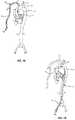
- FIG. 1Aschematically illustrates human arterial vasculature showing a transradial approach of a catheter to a position near the aortic root;
- FIG. 1Bschematically illustrates human arterial vasculature showing a transfemoral approach of a catheter to a position near the aortic root;
- FIG. 2illustrates an enlarged view of the aorta, showing a desired positioning of the catheter within the aorta for accessing a coronary artery;
- FIG. 3illustrates an exemplary catheter device which may be utilized for accessing a coronary artery, the catheter device having a proximal section, a preferred bending intermediate section, a rigid intermediate section, and a flexible distal section;
- FIGS. 4A through 4Dillustrate various beam configurations that may be utilized in various combinations to provide desired bending characteristics in the intravascular device
- FIG. 5illustrates a cutting pattern with a helical arrangements of beams
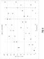
- FIG. 6graphically illustrates a distributed cut pattern and shows a typical helical pattern for comparison
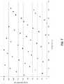
- FIG. 7graphically illustrates an imperfect ramp cut pattern
- FIG. 8graphically illustrates a sawtooth cut pattern and shows a typical helical pattern for comparison
- FIGS. 9 and 10illustrate differences in rotational offsets, showing differences in spacing artifacts resulting from different sizes of rotational offset jumps.
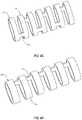
- FIGS. 11A through 11Cillustrate various spiral cut patterns that may be utilized to provide desired bending characteristics in the distal section of the intravascular device.
- the present disclosurerelates to interventional catheter devices having features that provide for effective positioning at the aortic root and effective access to a targeted coronary artery.
- interventional catheter deviceshaving features that provide for effective positioning at the aortic root and effective access to a targeted coronary artery.
- Embodiments described hereininclude different catheter sections of varied construction that are arranged to provide functional positioning benefits.
- the following descriptionrefers to a proximal section, an intermediate section, and a distal section.
- the intermediate sectionincludes two sub-sections which collectively form the intermediate section.
- the proximal-intermediate sectionis the more proximal part of the intermediate section which couples to the proximal section of the catheter and extends distally therefrom.
- the distal-intermediate sectionis the more distal part of the intermediate section which couples to the distal section of the catheter and extends proximally therefrom.
- the intermediate sectionincludes features which enable effective positioning and stabilization of the catheter at a position in the aorta near the aortic root.
- the proximal-intermediate sectionincludes a preferred bending axis allowing it to flex in one plane at the base of the aortic root
- the distal-intermediate sectionincludes a relatively rigid construction to provide support across the base of the aortic root.
- references to components or features which are configured to get progressively wider, narrower, shallower, deeper, more or less flexible, etc.are intended to disclose components or features which, on average, progress in the manner described. Accordingly, embodiments that include one or more areas that depart from the overall average progression are still within the scope of the description.
- references to a component or feature that progressively changes in some manner as it gets closer to one end of the devicemay be considered to progressively change, on average, if the change is apparent over at least about 0.5, 1, 3, or 5 cm of axial length of the device, or over an axial length within a range defined by any two of the foregoing values.
- FIGS. 1A and 1Billustrate possible transvascular approaches for reaching the aortic root.
- FIG. 1Ashows a transradial approach, where the catheter 50 is inserted into the radial artery 18 (typically the right radial artery) and passed into the corresponding subclavian artery and then into the aortic arch 12 . From the aortic arch 12 , the distal tip of the catheter 50 is further directed into the ascending aorta 14 and to the aortic root 16 .
- FIG. 1Ashows a transradial approach, where the catheter 50 is inserted into the radial artery 18 (typically the right radial artery) and passed into the corresponding subclavian artery and then into the aortic arch 12 . From the aortic arch 12 , the distal tip of the catheter 50 is further directed into the ascending aorta 14 and to the aortic root 16 .
- FIG. 1Billustrates a transfemoral approach, where the catheter 50 is inserted into the femoral artery 20 , then passed retrograde into the descending aorta 22 , and further directed around the aortic arch 12 and toward the aortic root 16 .
- theseare the most common approaches, other approaches may also be utilized (e.g., a transbrachial approach).
- the particular approach utilizedmay depend on physician preference, patient anatomy, procedural necessities, and the like.
- the catheter embodiments described hereinmay be utilized for any such approach to the aortic root 16 .
- FIG. 2illustrates a preferred catheter position near the aortic root 16 .
- the procedureusually requires further passage into one of the coronary arteries.
- FIG. 2illustrates entry into the right coronary artery 24 ; however, catheter embodiments described herein may also be utilized to access the left coronary artery in procedures where such access is desired.
- a portion of the catheter 50preferably contacts the aortic wall at a point 26 opposite the targeted coronary artery (the right coronary artery 24 in this example).
- This contactbeneficially supports and stabilizes the catheter 50 .
- achieving this positionintroduces its own challenges. From the point of contact 26 against the aortic wall opposite the targeted coronary artery 24 , the catheter 50 must provide a relatively sharp bend 54 to extend across the aortic root 16 and reach the artery 24 .
- the catheter 50must be flexible enough to provide the illustrated bend 54 . However, excessive flexibility in the portion of the catheter extending across the aortic root 16 may leave that portion subject to “sagging” or “bouncing” movements, as indicated by arrows 56 .
- catheter embodiments described hereininclude features which minimize or eliminate the foregoing limitations.
- the catheter device embodimentsmay be utilized to provide stable, effective catheter placement at the aortic root, which may allow more accurate and effective access to coronary arteries and better procedural outcomes.
- FIG. 3illustrates an exemplary embodiment of a catheter 100 capable of effective positioning at the aortic root.
- the illustrated catheter 100includes a proximal section 102 , an intermediate section 104 , and a distal section 110 .
- the proximal section 102is further divided into a braided region 114 and a microfabricated region 112 .
- the braided region 114may be bonded to the microfabricated region 112 by including a machined-down step (not shown) in the catheter where the braid may be bonded to the catheter using epoxy or other suitable adhesive.
- the intermediate sectionis further divided into a proximal-intermediate section 106 and a distal-intermediate section 108 .
- the microfabricated region 112 of the proximal section 102includes features that provide flexibility while maintaining sufficient strength for effective torquability and pushability of the device.
- the microfabricated region 112has a two-beam configuration with successive beam pairs arranged to form a helical pattern along the length of the microfabricated region 112 . As shown, spacing between cut pairs grows progressively narrower as the microfabricated region 112 extends closer to the intermediate section 104 . This provides the microfabricated region 112 with progressively higher flexibility in the distal direction. The flexibility differential beneficially balances catheter strength with flexibility. In more proximal regions of the device, good torquability is important, and closer to the distal end of the device, flexibility becomes increasingly important.
- the proximal-intermediate section 106extends distally from the proximal section 102 .
- the proximal-intermediate section 106is configured to provide the bend at the aortic wall to enable the more distal sections of the catheter to extend across the aortic root and into the targeted coronary artery (see FIG. 2 ).
- the proximal-intermediate section 106includes cuts aligned on the same side, leaving a resulting “spine” and allowing the section to preferentially flex in one plane at the base of the aortic root. Substantially limiting the bending axis to a single plane allows for easier alignment of the distal tip of the catheter with the opening of the targeted coronary artery.
- the distal-intermediate section 108is more rigid than both the proximal-intermediate section 106 and the distal section 110 . This beneficially provides support as the catheter extends from the aortic wall across the base of the aortic root toward the opening of the targeted coronary artery.
- the higher rigidity of the distal-intermediate section 108functions to limit movement of the catheter in that region, which enables more effective positioning of the distal tip of the catheter.
- the distal-intermediate section 108omits microfabricated cuts. Alternative embodiments may include some microfabricated cutting to provide a desired level of flexibility. However, even in such embodiments, the distal-intermediate section 108 preferably still has greater rigidity than both the distal section 110 and the proximal-intermediate section 106 .
- the distal section 110extends from the distal-intermediate section 108 to an atraumatic distal tip 116 of the device.
- the distal section 110may include a microfabricated cut pattern to provide greater flexibility.
- the distal section 110is configured to have greater flexibility than the microfabricated region 112 of the proximal section 102 .
- the cuts of the distal sectionmay be deeper and/or more narrowly spaced.
- Much of the catheter 100may beneficially be formed of a single integral piece of stock material, with the different sections being defined by different cut patterns (or lack thereof) rather than by separate pieces joined together at connecting joints.
- at least the distal section, intermediate section, and microfabricated region of the proximal sectionmay be formed from the same integral piece of stock material.
- the catheter 100is formed from a metals and/or alloys (e.g., nickel titanium), though other suitable medical-grade materials may also be used, including other medical-grade polymers such as polyetheretherketone (PEEK).
- PEEKpolyetheretherketone
- the catheter 100is formed from a single piece of material, although in alternative embodiments two or more separate pieces of material may be joined together to form the catheter 100 .
- the catheter 100may also include an outer laminate made from a suitable medical-grade material.
- a polymer laminate of variable durometerforms an outer coating of the catheter 100 .
- the laminatemay have a higher durometer along the proximal section 102 and a lower durometer along the distal section 110 .
- the laminatemay have an intermediate durometer along the intermediate section 104 .
- the laminate along the proximal-intermediate section 106may have a relatively low durometer (e.g., similar to that at the distal section 110 ) while the laminate along the distal-intermediate section 108 may have a relatively high durometer (e.g., similar to that at the proximal section 102 ).
- Some embodimentsmay also use laminate with various gradations of durometer and/or progressively changing durometer values.
- the laminate along one or more sectionsmay have a progressively decreasing durometer in the distal direction.
- the catheter 100may also include a liner made from a suitable medical-grade material.
- the lineris formed from polytetrafluoroethylene (PTFE), though alternative liner materials may also be utilized.
- PTFEpolytetrafluoroethylene
- a portion of the laminate and/or linerextend distally beyond the microfabricated stock material of the distal section 110 to form an atraumatic distal tip 116 .
- a typical embodimentmay have a total length of about 70 to 120 cm.
- the proximal section 102may have a length of about 60 to 90 cm, with about 50 to 80 cm of that length making up the braided region 114 and about 5 to 40 cm of that length making up the microfabricated region 112 .
- the intermediate section 104may have a length of about 2 to 5 cm, with about 1 to 3 cm of that length making up the proximal-intermediate section 106 and about 2 to 4 of that length making up the distal-intermediate section 108 .
- the distal section 110may have a length of about 1 to 3 cm.
- catheter sizesmay be varied according to particular application needs, a typical embodiment may have a size of about 4 to 9 F. Embodiments having dimensions within these ranges provide for effective catheter positioning at the aortic root.
- the various patterns described belowmay be utilized in the different microfabricated sections of the catheter 100 .
- the distal section 110 and/or the microfabricated region 112 of the proximal section 102preferably include one or more of the below described microfabricated features.
- Cut patterns described hereinmay have different configurations defined by the number of resulting longitudinal beams resulting from each set of cuts at a given longitudinal position along the device.
- each cut location along the length of the deviceincludes a pair of opposed cuts resulting in a pair of opposed, axially extending beams.
- the two beams within the resulting beam pairare symmetrically spaced about the circumference of the catheter (i.e., spaced about 180 degrees apart), though in other embodiments they may be differentially circumferentially spaced.
- the triad of beams in a three-beam configurationare typically symmetrically spaced about the circumference by about 120 degrees
- the set of beams in a four-beam configurationare typically spaced about the circumference by about 90 degrees
- other embodimentsmay include differential circumferential spacing.
- Embodimentsmay include multiple sections each having a different beam configuration to provide different respective flexibility characteristics and a desired flexibility gradient across the length of the device.
- a particular section having a particular beam configurationcan include cuts arranged to provide a flexibility gradient within the particular section itself. For example, longitudinal spacing between cuts may be progressively less at areas closer to the distal end of the device. In this manner, a device may be configured to provide a desired flexibility profile across the length of the device by including both inter- and intra-sectional flexibility gradients.
- FIGS. 4A through 4Dillustrate various embodiments of cut patterns which may be utilized in the devices described herein.
- FIG. 4Ashows a “two-beam” configuration
- FIG. 4Bshows a “three-beam” configuration
- FIGS. 4C and 4Dshow different versions of a “one-beam” configuration.
- Other embodimentsmay include configurations of more than three resulting beams per cut location (e.g., a “four-beam” cut pattern, “five-beam” cut pattern, etc.). All other manufacturing parameters being equal, the higher the number of resulting beams at each cut position, the lower the flexibility and the higher the torquability of the section.
- an elongated section 300includes a plurality of axially extending beams 302 and circumferentially extending rings 304 .
- the elongated section 300has a two-beam cut pattern because two circumferentially opposing beams 302 are disposed between each pair of adjacent rings 304 .
- the opposing cuts in each cut pairwill typically have equal depth, leaving each beam of the resulting beam pair symmetrically circumferentially spaced.
- Other embodimentsmay include cut pairs with opposing cuts of differential depth. The greater the difference between the depths of opposing cuts in each cut pair, the closer together circumferentially the beams of the resulting beam pair will be, and therefore the more similar functionally the two-beam cut will be to a one-beam cut.
- the illustrated embodimentshows a distribution of beam pairs angularly offset by 90 degrees from one pair to the next along the axis of the member.
- the angular offsetmay be more or less than 90 degrees.
- the angular offsetmay be about 5, 15, 30, 45, 60, 75, 80, or 85 degrees (in either direction), or may include a plurality of different offset values.
- an angular offsetis applied at each successive beam pair. In other embodiments, an angular offset is applied at each successive “segment,” with each segment including more than one beam pair.
- a “segment”is a repeating structural unit of the catheter section.
- a single segmentcan be defined as a first pair of opposing beams 302 disposed between two adjacent rings 304 (one proximal ring and one distal ring) and a second pair of opposing beams extending from the distal ring and being rotationally offset by about 90 degrees from the first pair of opposing beams 302 .
- an embodiment having such segments and having a rotational offset of 5 degrees from segment to segmentwould have a first beam pair at a 0 degree position, a second at 90 degrees, a third at 5 degrees, a fourth at 95 degrees, etcetera.
- FIG. 4Billustrates an elongated section 400 having a plurality of beams 402 and rings 404 arranged in a three-beam configuration.
- each triad of beams at each cut locationis symmetrically circumferentially spaced by 120 degrees.
- An angular offset of 60 degreesis applied at each successive cut location.
- the beams of a triadneed not be symmetrically spaced.
- an angular offset of more or less than 60 degreesmay be used, and it may be applied at each successive cut location or at each successive segment.
- a segmentmay be defined as a first triad of beams 402 disposed between two adjacent rings 404 (one proximal ring and one distal ring) and a second triad of beams extending from the distal ring and being rotationally offset by about 60 degrees from the first triad 402 .
- FIG. 4Cillustrates an elongated section 500 having a series of beams 502 and rings 504 arranged in a one-beam configuration.
- An angular offset of 180 degreesis applied at each successive cut location.
- an angular offset of more or less than 180 degreesmay be used, and it may be applied at each successive cut location or at each successive segment.
- a segmentmay be defined as a first beam 502 disposed between two adjacent rings 504 (one proximal ring and one distal ring) and a second beam extending from the distal ring and being rotationally offset by about 180 degrees from the first beam 502 .
- FIG. 4Dillustrates another embodiment of an elongated section 600 having a series of beams 602 and rings 604 arranged in a one-beam configuration.
- the cutsare provided so that the beams 602 are aligned along one side of the section length, rather than having an angular offset.
- Such an embodimentcan beneficially provide preferential bending in one direction (i.e., toward the aligned beams 602 ).
- FIGS. 4C and 4Dare examples of one beam configurations where any combination of beams with a rotational offset or a series of beams aligned on one side can be used depending on the balance of performance attributes desired.
- two beams in successioncan be aligned followed by a beam being rotationally offset by some amount (e.g., 180 degrees).
- one beam offsetscan be aligned (0 degree offset), or can have a rotational offset of up to 180 degrees, including any angle in between (175 degrees, 135 degrees, 90 degrees, 45 degrees, 5 degrees, etc.).
- FIG. 5illustrates an embodiment of a typical helical cut pattern intended to minimize preferred bending directions.
- a rotational offsetis applied at each successive segment of the elongate member 900 to form the helical pattern.
- FIG. 5illustrates a helical one-beam cut pattern where each cut leaves a single beam 902 between each set of adjacent rings 904 .
- successive beamsare shown as being offset by about 180 degrees, each successive pair is part of a “segment,” and each successive segment is shown as having a rotational offset of about 5 degrees
- the rotational offsetmay be applied from segment to segment, as shown in FIG. 5 , or may alternatively be applied at each successive cut.
- This type of helical arrangementmay also be used in embodiments having different cut configurations.
- a two-beam configurationmay have a helical arrangement with rotational offset applied at each successive segment or at each successive cut pair.
- Some embodimentsmay include a section having a distributed beam arrangement resulting from a non-helical and non-linear cut pattern. This type of pattern effectively eliminates or minimizes preferred bending directions.
- FIG. 6graphically compares one example of a distributed pattern with a conventional helical pattern. As shown, the helical cut pattern applies a constant rotational offset from segment to segment along the length of the elongated member. The distributed cut pattern applies a rotational offset that effectively distributes bending axes without relying on a helical pattern.
- the helical and distributed patterns graphically shown in FIG. 6are for devices having a two-beam configuration. Since a typical two-beam configuration will space each beam pair apart by about 180 degrees, a beam pair at a given position will be indistinguishable from a beam pair rotationally offset by 180 degrees. Accordingly, the possible rotational positions for beam pairs are shown as ranging from 0 to 180 degrees, with the zero and 180 degree positions being equal to one another. Other distributed pattern embodiments may exhibit different rotational spacing. For example, a one-beam configuration will typically be distributed across the full available 360 degree rotational space, and a three-beam pattern will typically exhibit 120 degree symmetry, and therefore be distributed across a 120 degree rotational space.
- the distributed pattern shown in FIG. 6is “non-helical.”
- a helixis commonly defined as following a curve on a conical or cylindrical surface that would become a straight line if the surface were unrolled into a plane.
- any curved lines tracing the arrangement of the segments along the length of the elongated member 900would form straight lines if the elongated member 900 were cut open and “unrolled” into a plane.
- a rotational offset limitis also applied to prevent the formation of rigid spacing artifacts (discussed further below with respect to FIGS. 9 and 10 ).
- the rotational offset limitdefines a limit on the acceptable rotational “jump” from one beam pair to the next or from one segment to the next.
- a rotational offset limit with a value of about 10 to 30 degrees from one segment to the next, or a rotational offset limit that rotates successive beam pairs by 90 degrees ⁇ that value,has been shown to provide effective distribution of bending axes without causing overly rigid spacing artifacts.
- the rotational offset limitmay restrict rotation from one beam pair to the next to a value within a range of about 60 to 120 degrees, or about 70 to 110 degrees, or about 80 to 100 degrees.
- Other embodimentsmay utilize other rotational offset limits, or may even omit the rotational offset limit, depending on particular product and/or application needs.
- the rotational offset limitmay be raised to a value higher than 30 degrees if the resulting spacing artifacts are acceptable for a particular application.
- the exemplary distributed cut pattern illustrated in FIG. 6utilizes a rotational offset limit of 30 degrees.
- a first beam pairis positioned at an arbitrary 0 degree position, and the second beam pair is positioned at 90 degrees.
- the greatest remaining gaps in the available 180 degree spaceare between 0 and 90 degrees and between 90 and 180 degrees (where 0 and 180 degrees represent the same position).
- Placing the next beam pair near a midpoint of one of these gaps, such as at 45 degreeswould best distribute the bending axes of the device. However, placing the next beam pair at 45 degrees would violate the rotational offset limit of 30 degrees.
- the next beam pairis therefore placed to be close to the midpoint of a remaining gap without violating the rotational offset limit.
- the third beam pairis placed at 30 degrees.
- the fourth beam pairis placed at 120 degrees, which is 90 degrees from the third beam pair.
- every other beam pairis offset 90 degrees from the previous beam pair.
- Alternative embodimentsneed not necessarily follow this particular pattern.
- the illustrated embodimentis an example of varying the applied offset from segment to segment, other embodiments may apply the variable offset from beam pair to beam pair.
- the largest remaining positional gapsare now between 30 and 90 degrees and between 120 and 180 degrees.
- the fifth and sixth beam pairsare placed at 60 and 120 degrees, respectively.
- the remaining positional gapsare now located every 30 degrees (i.e., between 0 and 30 degrees, between 30 and 60 degrees, between 60 and 90 degrees, etc.).
- remaining angular positionsare filled in a manner that radially spaces beam pairs as fast as possible without violating the rotational offset limit.
- the available angular positionsare provided at a granularity of 10 degrees.
- all angular positionsmay be considered as filled when each 10 degree increment has been filled.
- the illustrated patternmay therefore includes beam pairs positioned at approximately every 10 degree position before resetting.
- Such an arrangementis referred to herein as having a “positional granularity” of 10 degrees.
- Alternative embodimentsmay utilize a different positional granularity, such as a granularity of 0.1, 0.5, 1, 3, 5, 10, 15, 18, 20, 25, or 30 degrees, for example.
- the positional gapsmay be filled using a different particular sequence as long as rotational jumps are within the predetermined rotational offset limit.
- the next beam pairis positioned to be close to the approximate center of the largest remaining positional gap without violating the rotational offset limit.
- the segmentmay be positioned at the 10 to 20 degree position.
- alternative embodimentsmay utilize a positional granularity that fills in positions of more or less than 10 degrees. Where fewer segments are used before resetting the pattern, the size range of each suitable position will be larger, and where more segments are used before resetting the pattern, the size ranges will become smaller. Some embodiments may include about 6 to 36 beam pairs, or about 10 to 18 beam pairs, before the availability of filled angular positions within the 180 degree radial space is reset. Other embodiments may include many more beam pairs before available positions are reset. As the predetermined positional granularity is lowered, the number of beam pairs needed to fill all available angular positions will rise. Thus, a device having a positional granularity of 1 degree will use 180 beam pairs to fill 180 available angular positions.
- the distributed cut patternneed not identically repeat itself after resetting. Therefore, as used herein, the terms “reset,” “resetting,” and the like refer to resetting the availability of angular positions within the 180 degree radial space after it has been filled by beam pairs, and the terms do not necessarily imply that the subsequent refilling of angular positions along the next section of the elongated member will exactly repeat the previous pattern. Indeed, in at least some embodiments, the entire length of the distributed pattern may be non-repeating.
- FIG. 7graphically illustrates another embodiment of a non-helical cut pattern formed by intentionally disrupting an otherwise helical pattern with a series of purposefully designed imperfections.
- This type of cut patternis referred to herein as an “imperfect ramp” pattern.
- the intentional divergences of an imperfect ramp patternbeneficially function to reduce or prevent preferred torsional and curvature relics inherent in a true helical arrangement.
- segmentsare arranged such that no three successive beam pairs or segments are spaced according to the same rotational offset. In other words, no three beam pairs or segments are arranged so as to form a straight line if the cylindrical elongated member were unrolled into a plane.
- a true helical patternis typically formed by rotationally offsetting each successive segment or each successive beam pair by a constant value.
- a true helical pattern in a two-beam structuremay be formed by rotationally offsetting each successive cut pair by a constant value of 5 degrees, 85 degrees, 95 degrees, or some other constant value that is not a multiple of 90 degrees.
- an imperfect ramp patternmay be formed by rotationally offsetting each successive beam pair by a constant value ⁇ a variable modifying value.
- a rotational offset that includes a constant value ⁇ a variable modifying valueis referred to herein as an “imperfect rotational offset.”
- the variable modifying valuemay range from 5 to 15 degrees. In other embodiments, the variable modifying value may range from 2.5 to 30 degrees, or some other range suitable for the intended purpose of the resulting device.
- the variable modifying valueis preferably randomly selected at each segment or beam pair to which it is applied, with upper and lower bounds of the random selection being defined by the modifying value range (e.g., 5 to 15 degrees).
- the constant value portion of the offsetis typically 180 degrees in a one beam pattern, 90 degrees in a two-beam pattern, 60 degrees in a three-beam pattern, etcetera.
- Alternative embodimentsmay apply the imperfect ramp pattern between segments of different sizes and/or between segments with different internal offsets.
- some embodimentsmay include segments having more than two pairs of beams (and more than two corresponding rings) and/or with internal offsets different than 90 degrees.
- the illustrated exampleshows a two-beam cut pattern where each pair of the opposing cuts results in two circumferentially opposing beams, it will be understood that the distributed offset patterns may also be applied to one-beam cut patterns, three-beam cut patterns, and patterns having more than three beams between adjacent rings.
- FIG. 8illustrates another embodiment of a non-helical cut pattern referred to herein as a “sawtooth” pattern.
- the sawtooth cut patterncan beneficially avoid preferred bending axes while also limiting preferred curvature directions inherent in helical patterns.
- a sawtooth cut patternperiodically reverses the direction of the rotational offset.
- Both the sawtooth pattern and the helical pattern of FIG. 8have an angular offset of about 10 degrees between adjacent segments, with each cut pair within each segment offset by 90 degrees. Whereas the helical pattern simply continues with these offset values in the same direction through multiple rotations around the circumference of the elongated member, the sawtooth pattern reaches a first apex position before reversing direction and continuing toward a second apex position. Upon reaching the second apex position, the sawtooth pattern then reverses again and continues back toward the first apex. The pattern then repeats along the desired length of the elongated member.
- the first apex positionis set at about 90 degrees (i.e., 90 degrees for the first cut pair of the segment and 180 degrees for the second cut pair of the segment).
- the patternreverses toward the second apex position.
- the second apex positionis set at about 0 degrees (i.e., 0 degrees for the first cut pair of the segment and 90 degrees for the second cut pair of the segment).
- Alternative embodimentsmay include other apex positions.
- the first apex positionis less than 360 degrees in a one-beam configuration, less than 180 degrees in a two-beam configuration, less than 120 degrees in a three-beam configuration, and so on.
- the first apex positionis about 180 degrees for a one-beam configuration, 90 degrees for a two-beam configuration, 60 degrees for a three-beam configuration, and so on.
- the angular offset from segment to segment in the sawtooth pattern of FIG. 8is about 10 degrees. In other embodiments of sawtooth cut patterns, the angular offset may be more or less than 10 degrees, such as from about 5 degrees to about 30 degrees. Additionally, or alternatively, portions of the cut pattern between the apexes may include a variable offset. For example, one or more portions between the apexes may include an imperfect rotational offset such as described above in relation to FIG. 7 .
- Alternative embodimentsmay apply the sawtooth pattern between segments of different sizes and/or between segments with different internal offsets.
- some embodimentsmay include segments having more than two pairs of beams (and more than two corresponding rings) and/or with internal offsets different than 90 degrees.
- the illustrated exampleshows a two-beam cut pattern where each pair of the opposing cuts results in two circumferentially opposing beams, it will be understood that the distributed offset patterns may also be applied to one-beam cut patterns, three-beam cut patterns, and patterns having more than three beams between adjacent rings.
- FIG. 9illustrates an example of an undesirable spacing artifact that may result where a rotational offset limit is not applied.
- FIG. 9illustrates a section of an elongated member 700 having a first segment 750 a and a second segment 750 b .
- the first segment 750 aincludes a first pair of beams 730 a (only one of which is visible in this view) and second pair of beams 730 b and 730 c which are offset from the first pair by 90 degrees.
- the second segment 750 bincludes a first pair of beams 730 d and 730 e , and a second pair of beams 730 f and 730 g which are offset from the first pair by 90 degrees.
- Each beam within a pairis circumferentially spaced from its corresponding beam by 180 degrees.
- the second segment 750 bis offset from the first segment 750 a by 45 degrees, which positions the first pair of beams 730 d and 730 e off by 45 degrees from the first pair of beams 730 a and positions the second pair of beams 730 f and 730 g off by 45 degrees from the second pair of beams 730 b and 730 c.
- the beam 730 eis only spaced from the beam 730 c by 45 degrees, whereas the beam 730 d is spaced from the beam 730 c by 135 degrees. This disproportionate spacing may be undesirable because the region of the elongated member 700 having the smaller spacing may be overly rigid and/or the region having the larger spacing may be overly flexible.
- FIG. 10illustrates a section of an elongated member 800 with a more limited rotational offset of about 20 degrees applied between a first segment 850 a and a second segment 850 b .
- the first segment 850 aincludes a first pair of beams 830 a and a second pair of beams 830 b and 830 c
- the second segment 850 bincludes a first pair of beams 830 d and 830 e and a second pair of beams 830 f and 830 g .
- the spacing discrepancy between beams 830 b , 830 c , 830 d , and 830 eis less pronounced.
- Beam 830 dis spaced 70 degrees from beam 830 b
- beam 830 eis spaced 110 degrees from beam 830 b
- beam 830 eis spaced 70 degrees from beam 830 c
- beam 830 dis spaced 110 degrees from beam 830 c .
- FIGS. 11A through 11Cillustrate embodiments of a “spiral” cut pattern that may be included in one or more sections of the device.
- a section 170 of deviceis cut to provide an outer body of resulting helically oriented coil members 174 , with the pitch of the resulting coil defining the size of the fenestrations.
- a spiral cut patternprovides less torquability and more flexibility than a one-beam pattern. As such, in most applications, spiral sections are less beneficial at more proximal sections of the device where torquability concerns are particularly important, but are beneficial at more distal sections, and particularly at or near the distal end of the device, where flexibility concerns become more important.
- the spiral cut section 170forms an integral piece of material with one or more adjacent sections of the elongated device.
- the spiral patternresults from a cutting operation performed on the section.
- a single piece of materialcan be microfabricated to include one or more sections of different cut arrangements, in addition to the one or more spiral cut patterns.
- FIG. 11Aalso includes a series of bridges 172 that remain between and connect adjacent coil members 174 of the spiral pattern.
- Such bridges 172can function to somewhat limit the flexibility of the section 170 relative to a similar spiral pattern omitting such bridges.
- FIG. 11Billustrates another spiral cut section 180 that may be included in the hollow elongated member 104 .
- the spiral cut pattern of section 180omits bridges between coil members 184 , and therefore has relatively greater flexibility than the spiral section 170 shown in FIG. 11A (assuming materials, pitch, diameter, wall thickness, and other relevant factors are otherwise substantially equal).
- Bridges 172can also be arranged to provide flexibility bias in one or more directions.
- the bridges 172may be spaced about every 45, 60, 75, 90, 105, 120, 135, 150, 165, or 180 degrees around the spiral shape of the device. Greater spacing may also be provided between successive bridges. For example, multiples of 360 degrees may be added to any of the foregoing angle spacing values to provide an even greater spacing arrangement. Less spacing generally limits flexibility to a greater degree, while greater spacing generally provides greater relative flexibility.
- one or more of the bridges 172may be aligned with the longitudinal axis. Additional or alternative bridges may be oriented at an angle relative to the longitudinal axis.
- one or more of the bridges 172may be straight, while additional or alternative bridges may include bends or curved sections, or may include a non-uniform cross-sectional area.
- the bridges 172may therefore be modified to adjust the bending, torsional, or axial stiffness of the part as desired.
- spacing of the bridges 172can vary across the length of the section 170 . For example, spacing between the bridges 172 can become progressively greater toward the distal end of the section in order to progressively increase distal flexibility.
- FIG. 11Cillustrates, in cross-sectional view, an embodiment of a section 190 where spacing between spiral cuts is tailored to be progressively narrower as the cuts near the distal end of the section.
- the dimension 191 between two of the coil members 194is smaller at a more distal region than the dimension 193 between more proximally located coil members 192 .
- the cut widthindicated by dimension 195 , is substantially constant.
- the cut width 195may be adjusted as an alternative to or in addition to the progressive changes in coil member size shown by dimensions 191 and 193 .
- Other embodimentsmay omit progressively changing features, or may include one or more sections including progressively changing features and one or more other sections with substantially constant coil dimensionality.
- the terms “approximately,” “about,” and “substantially” as used hereinrepresent an amount or condition close to the stated amount or condition that still performs a desired function or achieves a desired result.
- the terms “approximately,” “about,” and “substantially”may refer to an amount or condition that deviates by less than 10%, or by less than 5%, or by less than 1%, or by less than 0.1%, or by less than 0.01% from a stated amount or condition.
- any embodiment described hereinmay be combined with features and components of any other embodiment.
- any combination of the different microfabricated cut patterns described hereinmay be utilized in the microfabricated sections of the exemplary catheter device of FIG. 3 .
Landscapes
- Health & Medical Sciences (AREA)
- Life Sciences & Earth Sciences (AREA)
- Biophysics (AREA)
- Pulmonology (AREA)
- Engineering & Computer Science (AREA)
- Anesthesiology (AREA)
- Biomedical Technology (AREA)
- Heart & Thoracic Surgery (AREA)
- Hematology (AREA)
- Animal Behavior & Ethology (AREA)
- General Health & Medical Sciences (AREA)
- Public Health (AREA)
- Veterinary Medicine (AREA)
- Media Introduction/Drainage Providing Device (AREA)
Abstract
Description
Claims (20)
Priority Applications (9)
| Application Number | Priority Date | Filing Date | Title |
|---|---|---|---|
| US16/281,046US11305095B2 (en) | 2018-02-22 | 2019-02-20 | Microfabricated catheter having an intermediate preferred bending section |
| EP19710207.2AEP3727551B1 (en) | 2018-02-22 | 2019-02-21 | Microfabricated catheter having an intermediate preferred bending section |
| PCT/US2019/019046WO2019165144A1 (en) | 2018-02-22 | 2019-02-21 | Microfabricated catheter having an intermediate preferred bending section |
| CN201980013739.7ACN111902183B (en) | 2018-02-22 | 2019-02-21 | Microfabricated catheter with intermediate preferential bend section |
| KR1020207024999AKR20200123429A (en) | 2018-02-22 | 2019-02-21 | Micro-machined catheter with middle priority bend |
| CA3089737ACA3089737A1 (en) | 2018-02-22 | 2019-02-21 | Microfabricated catheter having an intermediate preferred bending section |
| AU2019226089AAU2019226089A1 (en) | 2018-02-22 | 2019-02-21 | Microfabricated catheter having an intermediate preferred bending section |
| JP2020543513AJP7404251B2 (en) | 2018-02-22 | 2019-02-21 | Microfabricated catheter with intermediate preferential bending section |
| US17/564,543US12053595B2 (en) | 2018-02-22 | 2021-12-29 | Microfabricated catheter having an intermediate preferred bending section |
Applications Claiming Priority (2)
| Application Number | Priority Date | Filing Date | Title |
|---|---|---|---|
| US201862633939P | 2018-02-22 | 2018-02-22 | |
| US16/281,046US11305095B2 (en) | 2018-02-22 | 2019-02-20 | Microfabricated catheter having an intermediate preferred bending section |
Related Child Applications (1)
| Application Number | Title | Priority Date | Filing Date |
|---|---|---|---|
| US17/564,543ContinuationUS12053595B2 (en) | 2018-02-22 | 2021-12-29 | Microfabricated catheter having an intermediate preferred bending section |
Publications (2)
| Publication Number | Publication Date |
|---|---|
| US20190255290A1 US20190255290A1 (en) | 2019-08-22 |
| US11305095B2true US11305095B2 (en) | 2022-04-19 |
Family
ID=67617445
Family Applications (2)
| Application Number | Title | Priority Date | Filing Date |
|---|---|---|---|
| US16/281,046Active2039-04-26US11305095B2 (en) | 2018-02-22 | 2019-02-20 | Microfabricated catheter having an intermediate preferred bending section |
| US17/564,543Active2039-06-02US12053595B2 (en) | 2018-02-22 | 2021-12-29 | Microfabricated catheter having an intermediate preferred bending section |
Family Applications After (1)
| Application Number | Title | Priority Date | Filing Date |
|---|---|---|---|
| US17/564,543Active2039-06-02US12053595B2 (en) | 2018-02-22 | 2021-12-29 | Microfabricated catheter having an intermediate preferred bending section |
Country Status (8)
| Country | Link |
|---|---|
| US (2) | US11305095B2 (en) |
| EP (1) | EP3727551B1 (en) |
| JP (1) | JP7404251B2 (en) |
| KR (1) | KR20200123429A (en) |
| CN (1) | CN111902183B (en) |
| AU (1) | AU2019226089A1 (en) |
| CA (1) | CA3089737A1 (en) |
| WO (1) | WO2019165144A1 (en) |
Cited By (7)
| Publication number | Priority date | Publication date | Assignee | Title |
|---|---|---|---|---|
| US20210008351A1 (en)* | 2016-09-14 | 2021-01-14 | Scientia Vascular, Llc | Integrated coil vascular devices |
| US20210393924A1 (en)* | 2020-06-19 | 2021-12-23 | Becton, Dickinson And Company | Vascular access instrument and related devices and methods |
| US20230071512A1 (en)* | 2021-09-03 | 2023-03-09 | Scientia Vascular, Inc. | Microcatheter device with non-linear bending stiffness |
| US12011555B2 (en) | 2019-01-15 | 2024-06-18 | Scientia Vascular, Inc. | Guidewire with core centering mechanism |
| US12053595B2 (en) | 2018-02-22 | 2024-08-06 | Scientia Vascular, Inc. | Microfabricated catheter having an intermediate preferred bending section |
| US12220538B2 (en) | 2008-12-08 | 2025-02-11 | Scientia Vascular, Inc. | Micro-fabricated intravascular devices having varying diameters |
| US12310567B2 (en) | 2017-05-26 | 2025-05-27 | Scientia Vascular, Inc. | Micro-fabricated medical device having a non-helical cut arrangement |
Families Citing this family (69)
| Publication number | Priority date | Publication date | Assignee | Title |
|---|---|---|---|---|
| US11406791B2 (en) | 2009-04-03 | 2022-08-09 | Scientia Vascular, Inc. | Micro-fabricated guidewire devices having varying diameters |
| US10285720B2 (en) | 2014-03-11 | 2019-05-14 | Neuravi Limited | Clot retrieval system for removing occlusive clot from a blood vessel |
| JP6595513B2 (en) | 2014-06-13 | 2019-10-23 | ニューラヴィ・リミテッド | Device for removal of acute occlusions from blood vessels |
| US10265086B2 (en) | 2014-06-30 | 2019-04-23 | Neuravi Limited | System for removing a clot from a blood vessel |
| US9918718B2 (en) | 2014-08-08 | 2018-03-20 | DePuy Synthes Products, Inc. | Embolic coil delivery system with retractable mechanical release mechanism |
| US11207502B2 (en) | 2016-07-18 | 2021-12-28 | Scientia Vascular, Llc | Guidewire devices having shapeable tips and bypass cuts |
| US11052228B2 (en) | 2016-07-18 | 2021-07-06 | Scientia Vascular, Llc | Guidewire devices having shapeable tips and bypass cuts |
| US10646689B2 (en) | 2016-07-29 | 2020-05-12 | Cephea Valve Technologies, Inc. | Mechanical interlock for catheters |
| EP3500191B1 (en) | 2016-08-17 | 2020-09-23 | Neuravi Limited | A clot retrieval system for removing occlusive clot from a blood vessel |
| US11452541B2 (en) | 2016-12-22 | 2022-09-27 | Scientia Vascular, Inc. | Intravascular device having a selectively deflectable tip |
| US10806462B2 (en) | 2017-12-21 | 2020-10-20 | DePuy Synthes Products, Inc. | Implantable medical device detachment system with split tube and cylindrical coupling |
| CN112261965A (en)* | 2018-06-11 | 2021-01-22 | 泰尔茂株式会社 | Diagnostic method, diagnostic system, and control method for diagnostic system |
| US11147562B2 (en) | 2018-12-12 | 2021-10-19 | DePuy Synthes Products, Inc. | Systems and methods for embolic implant detachment |
| ES2910600T3 (en) | 2019-03-04 | 2022-05-12 | Neuravi Ltd | Powered Clot Recovery Catheter |
| US11766539B2 (en) | 2019-03-29 | 2023-09-26 | Incept, Llc | Enhanced flexibility neurovascular catheter |
| US11253265B2 (en) | 2019-06-18 | 2022-02-22 | DePuy Synthes Products, Inc. | Pull wire detachment for intravascular devices |
| US11426174B2 (en)* | 2019-10-03 | 2022-08-30 | DePuy Synthes Products, Inc. | Medical device delivery member with flexible stretch resistant mechanical release |
| US11207494B2 (en) | 2019-07-03 | 2021-12-28 | DePuy Synthes Products, Inc. | Medical device delivery member with flexible stretch resistant distal portion |
| EP3791815B1 (en) | 2019-09-11 | 2024-06-26 | Neuravi Limited | Expandable mouth catheter |
| US12376859B2 (en) | 2019-09-17 | 2025-08-05 | DePuy Synthes Products, Inc. | Embolic coil proximal connecting element and stretch resistant fiber |
| US11439403B2 (en) | 2019-09-17 | 2022-09-13 | DePuy Synthes Products, Inc. | Embolic coil proximal connecting element and stretch resistant fiber |
| US11376013B2 (en) | 2019-11-18 | 2022-07-05 | DePuy Synthes Products, Inc. | Implant delivery system with braid cup formation |
| US11779364B2 (en) | 2019-11-27 | 2023-10-10 | Neuravi Limited | Actuated expandable mouth thrombectomy catheter |
| US11839725B2 (en) | 2019-11-27 | 2023-12-12 | Neuravi Limited | Clot retrieval device with outer sheath and inner catheter |
| EP4079367A4 (en)* | 2019-12-17 | 2024-01-10 | Lifetech Scientific (Shenzhen) Co., Ltd. | Delivery sheath and medical device |
| CN112971901B (en)* | 2019-12-17 | 2023-01-03 | 先健科技(深圳)有限公司 | Delivery sheath and medical instrument |
| CN112971899B (en)* | 2019-12-17 | 2023-01-03 | 先健科技(深圳)有限公司 | Delivery sheath and medical instrument |
| US11457922B2 (en) | 2020-01-22 | 2022-10-04 | DePuy Synthes Products, Inc. | Medical device delivery member with flexible stretch resistant distal portion |
| US12178975B2 (en) | 2020-01-23 | 2024-12-31 | Scientia Vascular, Inc. | Guidewire having enlarged, micro-fabricated distal section |
| US12343485B2 (en) | 2020-01-23 | 2025-07-01 | Scientia Vascular, Inc. | High torque guidewire device |
| US11432822B2 (en) | 2020-02-14 | 2022-09-06 | DePuy Synthes Products, Inc. | Intravascular implant deployment system |
| US11633198B2 (en) | 2020-03-05 | 2023-04-25 | Neuravi Limited | Catheter proximal joint |
| US11944327B2 (en) | 2020-03-05 | 2024-04-02 | Neuravi Limited | Expandable mouth aspirating clot retrieval catheter |
| EP4552680A3 (en)* | 2020-03-11 | 2025-07-16 | Stryker Corporation | Slotted catheter with fillers |
| US11883043B2 (en) | 2020-03-31 | 2024-01-30 | DePuy Synthes Products, Inc. | Catheter funnel extension |
| US11759217B2 (en)* | 2020-04-07 | 2023-09-19 | Neuravi Limited | Catheter tubular support |
| US20210393277A1 (en)* | 2020-06-18 | 2021-12-23 | Neuravi Limited | Catheter mouth designs |
| US11951026B2 (en) | 2020-06-30 | 2024-04-09 | DePuy Synthes Products, Inc. | Implantable medical device detachment system with flexible braid section |
| US12296112B2 (en)* | 2020-10-05 | 2025-05-13 | Scientia Vascular, Inc. | Microfabricated catheter devices with high axial strength |
| CN114533208B (en)* | 2020-11-24 | 2024-07-16 | 先健科技(深圳)有限公司 | Puncture sheath and bending-adjustable system |
| CN112649969A (en)* | 2020-12-28 | 2021-04-13 | 温州圣蓝工贸有限公司 | Thin elastic alloy glasses leg |
| EP4271455A1 (en)* | 2020-12-29 | 2023-11-08 | Stryker Corporation | Medical devices with tubular reinforcement |
| US11872354B2 (en) | 2021-02-24 | 2024-01-16 | Neuravi Limited | Flexible catheter shaft frame with seam |
| KR20240012442A (en)* | 2021-05-26 | 2024-01-29 | 폴드 인코포레이티드 | Flexible catheters and related methods |
| US11998213B2 (en) | 2021-07-14 | 2024-06-04 | DePuy Synthes Products, Inc. | Implant delivery with modified detachment feature and pull wire engagement |
| US20230016149A1 (en)* | 2021-07-16 | 2023-01-19 | Medtronic, Inc. | Transcatheter valve delivery system with omnidirectional steering and methods of use thereof |
| US20230082226A1 (en)* | 2021-09-03 | 2023-03-16 | Scientia Vascular, Inc. | Intravascular guidewire and microcatheter system |
| US11937839B2 (en) | 2021-09-28 | 2024-03-26 | Neuravi Limited | Catheter with electrically actuated expandable mouth |
| US12011186B2 (en) | 2021-10-28 | 2024-06-18 | Neuravi Limited | Bevel tip expandable mouth catheter with reinforcing ring |
| US20230148846A1 (en)* | 2021-11-17 | 2023-05-18 | Greene Group Industries, Llc | Single Piece Stamped Flexure |
| US11937824B2 (en) | 2021-12-30 | 2024-03-26 | DePuy Synthes Products, Inc. | Implant detachment systems with a modified pull wire |
| US11844490B2 (en) | 2021-12-30 | 2023-12-19 | DePuy Synthes Products, Inc. | Suture linkage for inhibiting premature embolic implant deployment |
| US12011171B2 (en) | 2022-01-06 | 2024-06-18 | DePuy Synthes Products, Inc. | Systems and methods for inhibiting premature embolic implant deployment |
| US11937825B2 (en) | 2022-03-02 | 2024-03-26 | DePuy Synthes Products, Inc. | Hook wire for preventing premature embolic implant detachment |
| US12137915B2 (en) | 2022-03-03 | 2024-11-12 | DePuy Synthes Products, Inc. | Elongating wires for inhibiting premature implant detachment |
| US11937826B2 (en) | 2022-03-14 | 2024-03-26 | DePuy Synthes Products, Inc. | Proximal link wire for preventing premature implant detachment |
| US12402886B2 (en) | 2022-06-23 | 2025-09-02 | DePuy Synthes Products, Inc. | Detachment indicator for implant deployment |
| CN115253014B (en)* | 2022-06-24 | 2024-07-23 | 上海微创微航机器人有限公司 | Snake bone catheter, catheter system and design method of snake bone catheter |
| CN115410500A (en)* | 2022-08-18 | 2022-11-29 | 国网山东省电力公司青岛供电公司 | GIS equipment universal automatic storage and blocking red cloth equipment and its use method |
| US12396730B2 (en) | 2022-09-28 | 2025-08-26 | DePuy Synthes Products, Inc. | Braided implant with detachment mechanism |
| US20240108853A1 (en)* | 2022-09-29 | 2024-04-04 | Scientia Vascular, Inc. | Microfabricated intravascular device for aspiration procedures |
| CN115814239A (en)* | 2022-10-27 | 2023-03-21 | 王志坚 | double lumen microcatheter |
| EP4577280A1 (en) | 2022-11-16 | 2025-07-02 | Imds R&D Bv | A microcatheter for interventional cardiovascular and/or neurovascular applications |
| CN115624680B (en)* | 2022-12-07 | 2023-03-28 | 艾柯医疗器械(北京)股份有限公司 | System for establishing transcatheter intracranial catheter and transcatheter pathway |
| EP4410349A1 (en) | 2023-02-03 | 2024-08-07 | Imds R&D Bv | A microcatheter for interventional cardiovascular and/or neurovascular applications |
| WO2024205394A1 (en)* | 2023-03-29 | 2024-10-03 | Imds R&D B.V. | A catheter for delivering medical therapy to a remote site in a body |
| US12171917B1 (en) | 2024-01-08 | 2024-12-24 | Imperative Care, Inc. | Devices for blood capture and reintroduction during aspiration procedure |
| CN117861041B (en)* | 2024-01-09 | 2024-07-16 | 上海心玮医疗科技股份有限公司 | A microcatheter |
| EP4613316A1 (en) | 2024-03-07 | 2025-09-10 | Imds R&D Bv | A catheter for delivering medical therapy to a remote site in a body |
Citations (340)
| Publication number | Priority date | Publication date | Assignee | Title |
|---|---|---|---|---|
| US2022065A (en) | 1932-07-07 | 1935-11-26 | Frederick C Wappler | Therapeutic applicator device |
| US2187299A (en) | 1935-08-13 | 1940-01-16 | Burkhardt Otto Wilhelm | Dressing of individual blocks of stone |
| US3183702A (en) | 1960-11-21 | 1965-05-18 | Rca Corp | Method of and apparatus for cutting and deburring tubes |
| US3572334A (en) | 1968-11-27 | 1971-03-23 | Johnson & Johnson | Intravenous catheter placement unit |
| US3612058A (en) | 1968-04-17 | 1971-10-12 | Electro Catheter Corp | Catheter stylets |
| US3709271A (en) | 1971-07-01 | 1973-01-09 | Mc Farland L Co | Method and apparatus for deep incising poles |
| JPS485208Y1 (en) | 1970-07-28 | 1973-02-09 | ||
| JPS4845313Y1 (en) | 1969-08-06 | 1973-12-26 | ||
| US3920058A (en) | 1971-02-22 | 1975-11-18 | Willard H Walker | Method of sawing logs |
| US4163406A (en) | 1977-12-15 | 1979-08-07 | Genevieve I. Hanscom | Centering device for feeding articles to a food slicer |
| US4239069A (en) | 1979-08-10 | 1980-12-16 | Zimmerman Edwin H | Automatic cant production machine |
| US4416312A (en) | 1980-07-03 | 1983-11-22 | Kockums Industri A.B. | Guiding mechanism for timber cutting machines |
| JPS59102509A (en) | 1983-11-21 | 1984-06-13 | Fujikawa Seikou Kk | Double-acting multihead type drilling and slotting device |
| US4688540A (en) | 1984-12-27 | 1987-08-25 | Disco Abrasive Systems, Ltd. | Semiconductor wafer dicing machine |
| US4719924A (en) | 1986-09-09 | 1988-01-19 | C. R. Bard, Inc. | Small diameter steerable guidewire with adjustable tip |
| US4801297A (en)* | 1984-06-01 | 1989-01-31 | Edward Weck Incorporated | Catheter having slit tip |
| US4846186A (en) | 1988-01-12 | 1989-07-11 | Cordis Corporation | Flexible guidewire |
| US4895168A (en) | 1988-01-21 | 1990-01-23 | Schneider (Usa) Inc., A Pfizer Company | Guidewire with movable core and external tubular safety cover |
| US4989608A (en) | 1987-07-02 | 1991-02-05 | Ratner Adam V | Device construction and method facilitating magnetic resonance imaging of foreign objects in a body |
| US5047045A (en) | 1989-04-13 | 1991-09-10 | Scimed Life Systems, Inc. | Multi-section coaxial angioplasty catheter |
| US5069217A (en) | 1990-07-09 | 1991-12-03 | Lake Region Manufacturing Co., Inc. | Steerable guide wire |
| US5084022A (en) | 1989-10-04 | 1992-01-28 | Lake Region Manufacturing Company, Inc. | Graduated guidewire |
| US5095915A (en) | 1990-03-19 | 1992-03-17 | Target Therapeutics | Guidewire with flexible distal tip |
| US5102390A (en) | 1985-05-02 | 1992-04-07 | C. R. Bard, Inc. | Microdilatation probe and system for performing angioplasty in highly stenosed blood vessels |
| US5147317A (en) | 1990-06-04 | 1992-09-15 | C.R. Bard, Inc. | Low friction varied radiopacity guidewire |
| US5154725A (en) | 1991-06-07 | 1992-10-13 | Advanced Cardiovascular Systems, Inc. | Easily exchangeable catheter system |
| US5174302A (en) | 1990-12-04 | 1992-12-29 | Cordis Corporation | Variable radiopacity guidewire with spaced highly radiopaque regions |
| EP0521595A2 (en) | 1991-02-15 | 1993-01-07 | Ingemar H. Lundquist | Torquable catheter and method |
| WO1994006503A1 (en) | 1992-09-22 | 1994-03-31 | Target Therapeutics, Inc. | Detachable embolic coil assembly |
| US5315996A (en) | 1991-02-15 | 1994-05-31 | Lundquist Ingemar H | Torquable catheter and method |
| JPH06154335A (en) | 1992-11-16 | 1994-06-03 | Mitsubishi Cable Ind Ltd | Rigid graded torque tube and its production and catheter formed by using this torque tube |
| US5326374A (en) | 1992-12-01 | 1994-07-05 | Michael N. Ilbawi | Body-implantable device for controlling the size of a fluid passageway |
| WO1994019039A1 (en) | 1993-02-18 | 1994-09-01 | Scimed Life Systems, Inc. | Vascular access catheter and methods for manufacture |
| US5345945A (en) | 1990-08-29 | 1994-09-13 | Baxter International Inc. | Dual coil guidewire with radiopaque distal tip |
| US5372587A (en) | 1989-01-09 | 1994-12-13 | Pilot Cariovascular Systems, Inc. | Steerable medical device |
| JPH078560A (en) | 1993-06-29 | 1995-01-13 | Terumo Corp | Blood-vessel catheter |
| US5382259A (en) | 1992-10-26 | 1995-01-17 | Target Therapeutics, Inc. | Vasoocclusion coil with attached tubular woven or braided fibrous covering |
| US5385152A (en) | 1990-11-09 | 1995-01-31 | Boston Scientific Corporation | Guidewire for crossing occlusions in blood vessels |
| US5437288A (en) | 1992-09-04 | 1995-08-01 | Mayo Foundation For Medical Education And Research | Flexible catheter guidewire |
| US5441483A (en) | 1992-11-16 | 1995-08-15 | Avitall; Boaz | Catheter deflection control |
| US5506682A (en) | 1982-02-16 | 1996-04-09 | Sensor Adaptive Machines Inc. | Robot vision using targets |
| US5507751A (en) | 1988-11-09 | 1996-04-16 | Cook Pacemaker Corporation | Locally flexible dilator sheath |
| US5551444A (en) | 1995-05-31 | 1996-09-03 | Radius Medical Technologies, Inc. | Flexible guidewire with radiopaque outer coil and non-radiopaque inner coil |
| US5554114A (en) | 1994-10-20 | 1996-09-10 | Micro Therapeutics, Inc. | Infusion device with preformed shape |
| US5569218A (en)* | 1994-02-14 | 1996-10-29 | Scimed Life Systems, Inc. | Elastic guide catheter transition element |
| US5573867A (en) | 1996-01-31 | 1996-11-12 | Westinghouse Electric Corporation | Purge gas protected transportable pressurized fuel cell modules and their operation in a power plant |
| US5573520A (en) | 1991-09-05 | 1996-11-12 | Mayo Foundation For Medical Education And Research | Flexible tubular device for use in medical applications |
| JPH08308934A (en) | 1995-05-22 | 1996-11-26 | Piolax Inc | Medical tube |
| US5659205A (en) | 1996-01-11 | 1997-08-19 | Ebara International Corporation | Hydraulic turbine power generator incorporating axial thrust equalization means |
| US5673707A (en) | 1994-09-23 | 1997-10-07 | Boston Scientific Corporation | Enhanced performance guidewire |
| US5676659A (en) | 1993-11-12 | 1997-10-14 | Medtronic, Inc. | Small diameter, high torque catheter |
| US5685568A (en) | 1996-11-04 | 1997-11-11 | Pirrello; Roberta | Protective holder and display apparatus for business cards |
| US5685868A (en) | 1991-02-15 | 1997-11-11 | Lundquist; Ingemar H. | Torquable tubular assembly and torquable catheter utilizing the same |
| US5690120A (en) | 1996-05-24 | 1997-11-25 | Sarcos, Inc. | Hybrid catheter guide wire apparatus |
| WO1997043949A1 (en) | 1996-05-24 | 1997-11-27 | Sarcos, Inc. | Hybrid tubular guide wire for catheters |
| US5706826A (en) | 1995-03-02 | 1998-01-13 | Schneider (Europe) A.G. | Guide wire with helical coil |
| CA2266685A1 (en) | 1996-09-16 | 1998-03-19 | Sarcos, Inc. | Method and apparatus for forming cuts in catheters, guidewires and the like |
| US5741429A (en) | 1991-09-05 | 1998-04-21 | Cardia Catheter Company | Flexible tubular device for use in medical applications |
| US5746701A (en) | 1995-09-14 | 1998-05-05 | Medtronic, Inc. | Guidewire with non-tapered tip |
| US5792154A (en) | 1996-04-10 | 1998-08-11 | Target Therapeutics, Inc. | Soft-ended fibered micro vaso-occlusive devices |
| US5800454A (en) | 1997-03-17 | 1998-09-01 | Sarcos, Inc. | Catheter deliverable coiled wire thromboginic apparatus and method |
| US5833632A (en) | 1995-12-07 | 1998-11-10 | Sarcos, Inc. | Hollow guide wire apparatus catheters |
| US5833631A (en) | 1996-06-28 | 1998-11-10 | Target Therapeutics, Inc. | Fiber tip guidewire |
| US5842461A (en) | 1996-08-13 | 1998-12-01 | Tokyo Seimitsu Co., Ltd. | Dicing machine |
| WO1998058697A1 (en) | 1997-06-20 | 1998-12-30 | Medtronic Ave, Inc. | Variable stiffness angioplasty guidewire |
| US5860963A (en) | 1993-12-10 | 1999-01-19 | Schneider (Usa) Inc | Guiding catheter |
| WO1999004847A1 (en) | 1997-07-24 | 1999-02-04 | Micro Therapeutics, Inc. | Medical infusion wire |
| US5876356A (en) | 1997-04-02 | 1999-03-02 | Cordis Corporation | Superelastic guidewire with a shapeable tip |
| US5911717A (en) | 1997-03-17 | 1999-06-15 | Precision Vascular Systems, Inc. | Catheter deliverable thrombogenic apparatus and method |
| US5911715A (en) | 1994-02-14 | 1999-06-15 | Scimed Life Systems, Inc. | Guide catheter having selected flexural modulus segments |
| US5916194A (en) | 1996-05-24 | 1999-06-29 | Sarcos, Inc. | Catheter/guide wire steering apparatus and method |
| US5931830A (en) | 1995-12-07 | 1999-08-03 | Sarcos L.C. | Hollow coil guide wire apparatus for catheters |
| US5954672A (en) | 1997-05-21 | 1999-09-21 | Schneider (Europe) Gmbh | Controlled gap guidewire |
| JPH11294497A (en) | 1998-04-10 | 1999-10-26 | Nsk Warner Kk | Elastic tube type brake band |
| WO1999053824A2 (en) | 1998-04-23 | 1999-10-28 | Advanced Cardiovascular Systems, Inc. | Proximally tapered guidewire tip coil |
| US6004279A (en) | 1996-01-16 | 1999-12-21 | Boston Scientific Corporation | Medical guidewire |
| US6022343A (en) | 1998-09-03 | 2000-02-08 | Intratherapeutics, Inc. | Bridged coil catheter support structure |
| US6022369A (en) | 1998-02-13 | 2000-02-08 | Precision Vascular Systems, Inc. | Wire device with detachable end |
| US6027863A (en) | 1991-09-05 | 2000-02-22 | Intratherapeutics, Inc. | Method for manufacturing a tubular medical device |
| US6033288A (en) | 1998-10-29 | 2000-03-07 | Kulicke & Soffa Investments, Inc. | Monitoring system for dicing saws |
| US6033394A (en) | 1997-12-05 | 2000-03-07 | Intratherapeutics, Inc. | Catheter support structure |
| JP2000116787A (en) | 1998-10-16 | 2000-04-25 | Piolax Inc | Tube for medical treatment |
| US6056702A (en) | 1998-10-02 | 2000-05-02 | Cordis Corporation | Guidewire with outer sheath |
| US6063101A (en) | 1998-11-20 | 2000-05-16 | Precision Vascular Systems, Inc. | Stent apparatus and method |
| US6110164A (en) | 1997-12-05 | 2000-08-29 | Intratherapeutics, Inc. | Guideless catheter segment |
| US6139511A (en) | 1998-06-29 | 2000-10-31 | Advanced Cardiovascular Systems, Inc. | Guidewire with variable coil configuration |
| JP2000343313A (en) | 1999-05-29 | 2000-12-12 | Isao Yoshida | Grooving machine for plate material |
| US6168570B1 (en) | 1997-12-05 | 2001-01-02 | Micrus Corporation | Micro-strand cable with enhanced radiopacity |
| US6179828B1 (en) | 1999-03-19 | 2001-01-30 | Merit Medical Systems, Inc. | Infusion system with fixed occluding wire |
| US6183410B1 (en) | 1999-05-06 | 2001-02-06 | Precision Vascular Systems, Inc. | Radiation exposure device for blood vessels, body cavities and the like |
| US6214042B1 (en) | 1998-11-10 | 2001-04-10 | Precision Vascular Systems, Inc. | Micro-machined stent for vessels, body ducts and the like |
| US6228073B1 (en) | 1998-12-15 | 2001-05-08 | Medtronic, Inc. | Angiography luer hub having wings proximal to the plurality of grips and strain relief |
| US6245030B1 (en) | 1998-03-04 | 2001-06-12 | C. R. Bard, Inc. | Flexible kink resistant, low friction guidewire with formable tip, and method for making same |
| US6251086B1 (en) | 1999-07-27 | 2001-06-26 | Scimed Life Systems, Inc. | Guide wire with hydrophilically coated tip |
| CA2395149A1 (en) | 1999-12-22 | 2001-06-28 | Stephen C. Jacobsen | Torquable guiding member system |
| US6261246B1 (en) | 1997-09-29 | 2001-07-17 | Scimed Life Systems, Inc. | Intravascular imaging guidewire |
| US20010009980A1 (en) | 1998-12-30 | 2001-07-26 | Edward J. Lynch | Guidewire with multiple polymer jackets over distal and intermediate core sections |
| US6273881B1 (en)* | 1994-12-15 | 2001-08-14 | Ferdinand Kiemeneij | Catheter for percutaneous transradial approach |
| US6302870B1 (en) | 1999-04-29 | 2001-10-16 | Precision Vascular Systems, Inc. | Apparatus for injecting fluids into the walls of blood vessels, body cavities, and the like |
| US6306105B1 (en) | 1998-05-14 | 2001-10-23 | Scimed Life Systems, Inc. | High performance coil wire |
| US20020013540A1 (en) | 1999-12-22 | 2002-01-31 | Jacobsen Stephen C. | Coronary guidewire system |
| US6346091B1 (en) | 1998-02-13 | 2002-02-12 | Stephen C. Jacobsen | Detachable coil for aneurysm therapy |
| US6356791B1 (en) | 1998-06-12 | 2002-03-12 | Cardiac Pacemakers, Inc. | Modified guidewire for left ventricular access lead |
| US20020049392A1 (en) | 2000-10-20 | 2002-04-25 | Demello Richard M. | Composite guidewire |
| US20020062524A1 (en) | 1999-11-29 | 2002-05-30 | Vogland James H. | Mattress and sheet attachment assembly |
| US20020078808A1 (en) | 1996-09-16 | 2002-06-27 | Jacobsen Stephen C. | Micromachining system |
| US20020082524A1 (en) | 2000-12-21 | 2002-06-27 | Advanced Cardiovascular Systems, Inc. | Guidewire with tapered distal coil |
| US6436056B1 (en) | 1996-02-28 | 2002-08-20 | Boston Scientific Corporation | Polymeric implements for torque transmission |
| US6440088B1 (en) | 1996-05-24 | 2002-08-27 | Precision Vascular Systems, Inc. | Hybrid catheter guide wire apparatus and method |
| US6458867B1 (en) | 1999-09-28 | 2002-10-01 | Scimed Life Systems, Inc. | Hydrophilic lubricant coatings for medical devices |
| US6464651B1 (en) | 1999-11-22 | 2002-10-15 | Nipro Corporation | Guide wire |
| US6492615B1 (en) | 2000-10-12 | 2002-12-10 | Scimed Life Systems, Inc. | Laser polishing of medical devices |
| US6494894B2 (en) | 2000-03-16 | 2002-12-17 | Scimed Life Systems, Inc. | Coated wire |
| US20030009208A1 (en) | 2001-07-05 | 2003-01-09 | Precision Vascular Systems, Inc. | Torqueable soft tip medical device and method of usage |
| JP2003011117A (en) | 2001-07-05 | 2003-01-15 | Canon Inc | Columnar base material cutting method, columnar base material cutting device, ingot cutting method using light, ingot cutting device using light, and wafer manufacturing method |
| US20030023190A1 (en) | 2001-06-20 | 2003-01-30 | Micro Vention, Inc. | Medical devices having full or partial polymer coatings and their methods of manufacture |
| US6527732B1 (en) | 2000-10-17 | 2003-03-04 | Micro Therapeutics, Inc. | Torsionally compensated guidewire |
| US6527746B1 (en) | 2000-08-03 | 2003-03-04 | Ev3, Inc. | Back-loading catheter |
| US20030069522A1 (en) | 1995-12-07 | 2003-04-10 | Jacobsen Stephen J. | Slotted medical device |
| US6554820B1 (en) | 2000-03-08 | 2003-04-29 | Scimed Life Systems, Inc. | Composite flexible tube for medical applications |
| US6558355B1 (en) | 2000-12-29 | 2003-05-06 | Ethicon, Inc. | Flushable guidewire device |
| US20030093059A1 (en) | 2001-11-09 | 2003-05-15 | Scimed Life Systems, Inc. | Intravascular microcatheter having hypotube proximal shaft with transition |
| CN1422673A (en) | 2001-12-03 | 2003-06-11 | 朝日印帝克股份有限公司 | Medical guiding thread |
| US20030125641A1 (en) | 2001-12-27 | 2003-07-03 | Mo Jafari | Apparatus and method for joining two guide wire core materials without a hypotube |
| US6602207B1 (en) | 2000-07-19 | 2003-08-05 | Scimed Life Systems, Inc. | Guide wire stiffness transition element |
| US6606985B2 (en) | 2001-02-07 | 2003-08-19 | Disco Corporation | Dual-cutting method devoid of useless strokes |
| US6610046B1 (en) | 1999-04-30 | 2003-08-26 | Usaminanotechnology Inc. | Catheter and guide wire |
| US6627724B2 (en) | 1996-09-23 | 2003-09-30 | Aortech Biomaterials Pty Ltd | Polysiloxane-containing polyurethane elastomeric compositions |
| JP2004025340A (en) | 2002-06-25 | 2004-01-29 | Toshiba Corp | Surface processing method and device |
| WO2004011076A2 (en) | 2002-07-25 | 2004-02-05 | Boston Scientific Limited | Medical device for navigation through anatomy and method of making same |
| US20040039371A1 (en) | 2002-08-23 | 2004-02-26 | Bruce Tockman | Coronary vein navigator |
| US20040054349A1 (en) | 2002-09-12 | 2004-03-18 | Jerry Brightbill | Reinforced catheter and methods of making |
| US20040087933A1 (en) | 2002-09-18 | 2004-05-06 | Lee Jeong S. | Stiff guiding catheter liner material |
| US20040093060A1 (en) | 1999-11-17 | 2004-05-13 | Jacques Seguin | Prosthetic valve for transluminal delivery |
| US20040102719A1 (en) | 2002-11-22 | 2004-05-27 | Velocimed, L.L.C. | Guide wire control catheters for crossing occlusions and related methods of use |
| US20040122340A1 (en) | 2002-12-23 | 2004-06-24 | Anthony Vrba | Guidewire tip construction |
| US20040167440A1 (en) | 2003-02-26 | 2004-08-26 | Sharrow James S. | Multiple diameter guidewire |
| US20040186485A1 (en) | 2003-03-19 | 2004-09-23 | Jason Kear | Device for manipulating material in a tissue |
| US20040193140A1 (en) | 2003-03-27 | 2004-09-30 | Scimed Life Systems,Inc. | Medical device |
| US6805676B2 (en) | 2000-10-03 | 2004-10-19 | Cook Incorporated | Manoeuverable guide wire and method of using same |
| US20040225292A1 (en) | 2003-05-05 | 2004-11-11 | Sasso Ricardo C. | Bone anchor and methods of using the same |
| JP2004329552A (en) | 2003-05-07 | 2004-11-25 | Vayu:Kk | Liquid medicine administering catheter |
| US20040254450A1 (en) | 2003-05-27 | 2004-12-16 | Scimed Life Systems, Inc. | Medical device having segmented construction |
| US20050054953A1 (en) | 2003-09-05 | 2005-03-10 | Vance Products Incoporated D/B/A Cook Urological Incorporated | Double ended wire guide |
| US20050124976A1 (en) | 2003-12-04 | 2005-06-09 | Devens Douglas A.Jr. | Medical devices |
| US20050216049A1 (en) | 2004-03-29 | 2005-09-29 | Jones Donald K | Vascular occlusive device with elastomeric bioresorbable coating |
| US20050274384A1 (en) | 2004-06-10 | 2005-12-15 | Quang Tran | Medical devices and methods of making and using such devices |
| US20060041186A1 (en) | 2004-08-17 | 2006-02-23 | Vancaillie Thierry G | Continuous flow single sheath for endoscope |
| WO2006025931A1 (en) | 2004-08-31 | 2006-03-09 | Advanced Cardiovascular Systems, Inc. | Apparatus and method for joining stainless steel guide wire portion to nitinol portion, without a hypotube |
| USRE39018E1 (en) | 1997-12-01 | 2006-03-21 | Tokyo Seimitsu Co., Ltd. | High speed method of aligning cutting lines of a workplace using patterns |
| US20060074442A1 (en) | 2000-04-06 | 2006-04-06 | Revascular Therapeutics, Inc. | Guidewire for crossing occlusions or stenoses |
| US7024885B2 (en) | 2003-10-29 | 2006-04-11 | Consultoria Ss-Soluciones Sociedad Anonima | System and method for storing gases at low temperature using a cold recovery system |
| US20060089618A1 (en) | 2004-10-21 | 2006-04-27 | Mcferran Sean | Catheter with a pre-shaped distal tip |
| US20060112802A1 (en) | 2004-11-30 | 2006-06-01 | Disco Corporation | Cutting machine |
| US20060121218A1 (en) | 2004-11-24 | 2006-06-08 | Obara Robert Z | Medical devices with highly flexible coated hypotube |
| US7097624B2 (en) | 2000-10-05 | 2006-08-29 | Scimed Life Systems, Inc. | Multi-layer and multi-section coils for guide wire |
| US7110910B1 (en) | 2005-06-13 | 2006-09-19 | The Timken Company | Method and apparatus for determining the straightness of tubes and bars |
| US20060241519A1 (en) | 2002-03-22 | 2006-10-26 | Hikmat Hojeibane | Guidewire with deflectable tip |
| WO2006113863A2 (en) | 2005-04-20 | 2006-10-26 | Cook Incorporated | Medical apparatus for rapid insertion |
| US20060262474A1 (en) | 2005-05-23 | 2006-11-23 | Chih-Yi Chen | Thermal monitoring and response apparatus and method for computer unit |
| US20070010786A1 (en) | 2001-04-17 | 2007-01-11 | Salviac Limited | Catheter |
| CN1897892A (en) | 2003-11-20 | 2007-01-17 | 先进心血管系统公司 | Rapid-exchange delivery systems for self-expanding stents |
| US7182735B2 (en) | 2003-02-26 | 2007-02-27 | Scimed Life Systems, Inc. | Elongated intracorporal medical device |
| US20070100285A1 (en) | 2005-10-27 | 2007-05-03 | Boston Scientific Scimed, Inc. | Elongate medical device with continuous reinforcement member |
| US20070112331A1 (en) | 2005-11-16 | 2007-05-17 | Jan Weber | Variable stiffness shaft |
| US20070135763A1 (en) | 2005-12-12 | 2007-06-14 | Musbach Frank A | Micromachined medical devices |
| US20070142893A1 (en) | 2005-12-19 | 2007-06-21 | Buiser Marcia S | Embolic coils |
| CN101001660A (en) | 2004-08-05 | 2007-07-18 | 导管治疗有限公司 | steerable catheter |
| US20070167876A1 (en) | 2006-01-17 | 2007-07-19 | Euteneuer Charles L | Occluding guidewire and methods |
| US20070185415A1 (en) | 2005-07-07 | 2007-08-09 | Ressemann Thomas V | Steerable guide wire with torsionally stable tip |
| US20070221230A1 (en) | 2006-03-13 | 2007-09-27 | David Thompson | Minimally invasive lung volume reduction device and method |
| US7276062B2 (en) | 2003-03-12 | 2007-10-02 | Biosence Webster, Inc. | Deflectable catheter with hinge |
| US20070233039A1 (en) | 2006-03-29 | 2007-10-04 | Vladimir Mitelberg | Joined metal tubing and method of manufacture |
| US20070250036A1 (en) | 2006-04-25 | 2007-10-25 | Boston Scientific Scimed, Inc. | Variable stiffness catheter assembly |
| US20070287955A1 (en) | 2002-07-25 | 2007-12-13 | Boston Scientific Scimed, Inc. | Tubular member having tapered transition for use in a medical device |
| US20080064989A1 (en) | 2006-09-13 | 2008-03-13 | Boston Scientific Scimed, Inc. | Crossing guidewire |
| US20080077049A1 (en) | 2006-08-24 | 2008-03-27 | Boston Scientific Scimed, Inc. | Elongate medical device including deformable distal end |
| US20080086854A1 (en) | 2002-12-10 | 2008-04-17 | Boyd Robert R | Articulated Elements And Methods For Use |
| US20080097248A1 (en) | 2006-08-16 | 2008-04-24 | Boston Scientific Scimed, Inc. | Mechanical honing of metallic tubing for soldering in a medical device construction |
| US20080097247A1 (en) | 2006-09-06 | 2008-04-24 | Boston Scientific Scimed, Inc. | Medical device including structure for crossing an occlusion in a vessel |
| US20080097246A1 (en) | 2006-09-10 | 2008-04-24 | Abbott Diabetes Care, Inc | Method and System for Providing An Integrated Analyte Sensor Insertion Device and Data Processing Unit |
| US20080119869A1 (en) | 2006-11-21 | 2008-05-22 | Boston Scientific Scimed, Inc. | Medical retrieval devices |
| US20080125674A1 (en) | 2004-06-11 | 2008-05-29 | Deniz Bilecen | Catheter Guide Wire, in Particular for Cardiovascular interventions |
| US20080122226A1 (en) | 2006-11-29 | 2008-05-29 | Ebara International Corporation | Compact assemblies for high efficiency performance of cryogenic liquefied gas expanders and pumps |
| US20080147170A1 (en) | 2006-12-15 | 2008-06-19 | Boston Scientific Scimed, Inc. | Medical device including structure for crossing an occlusion in a vessel |
| CN101209365A (en) | 2006-12-28 | 2008-07-02 | 朝日印帝克股份有限公司 | A medical guide wire |
| US20080188928A1 (en) | 2005-09-16 | 2008-08-07 | Amr Salahieh | Medical device delivery sheath |
| US20080188298A1 (en) | 2007-02-05 | 2008-08-07 | Atlantic City Cion & Slot Service Company, Inc. | Progressive gaming device and method of use |
| US20080200839A1 (en) | 2007-02-15 | 2008-08-21 | Vance Products Inc., D/B/A Cook Urological | Dual stiffness wire guide |
| US7421929B2 (en) | 2001-10-11 | 2008-09-09 | Andrew French | Drive apparatus |
| US20080262474A1 (en) | 2007-04-20 | 2008-10-23 | Boston Scientific Scimed, Inc. | Medical device |
| US20080269641A1 (en) | 2007-04-25 | 2008-10-30 | Medtronic Vascular, Inc. | Method of using a guidewire with stiffened distal section |
| AU2008229892A1 (en) | 1998-07-08 | 2008-10-30 | Bayer Essure, Inc. | Occluding device and method of use |
| CN101304778A (en) | 2005-09-16 | 2008-11-12 | 韦伯斯特生物官能公司 | Catheter with flexible pre-shaped tip section |
| US20080319525A1 (en) | 2007-06-25 | 2008-12-25 | Microvention, Inc. | Self-Expanding Prosthesis |
| US20090036833A1 (en) | 2007-08-02 | 2009-02-05 | Boston Scientific Scimed, Inc. | Composite elongate medical device including distal tubular member |
| US20090036832A1 (en) | 2007-08-03 | 2009-02-05 | Boston Scientific Scimed, Inc. | Guidewires and methods for manufacturing guidewires |
| WO2009020962A1 (en) | 2007-08-07 | 2009-02-12 | Boston Scientific Limited Inc. | Microfabricated catheter with improved bonding structure |
| US20090043372A1 (en) | 2007-08-06 | 2009-02-12 | Boston Scientific Scimed, Inc. | Alternative micromachined structures |
| WO2009020691A2 (en) | 2007-06-13 | 2009-02-12 | Scientific-Atlanta, Inc. | Frequency modulated burst mode optical system |
| US7494474B2 (en) | 1997-06-04 | 2009-02-24 | Advanced Cardiovascular Systems, Inc. | Polymer coated guidewire |
| US7507246B2 (en) | 1997-07-24 | 2009-03-24 | Rex Medical, L.P. | Rotational thrombectomy device |
| US20090118675A1 (en) | 2007-11-02 | 2009-05-07 | Boston Scientific Scimed, Inc. | Elongate medical device with a shapeable tip |
| CN201239164Y (en) | 2008-06-30 | 2009-05-20 | 扬州市瑞京科技发展有限公司 | Guide wire conveying device |
| US20090177185A1 (en) | 2008-01-03 | 2009-07-09 | Boston Scientific Scimed, Inc. | Cut tubular members for a medical device and methods for making and using the same |
| US20090177119A1 (en) | 2008-01-03 | 2009-07-09 | Boston Scientific Scimed, Inc. | Articulating intracorporeal medical device |
| US20090254000A1 (en) | 2008-04-07 | 2009-10-08 | Boston Scientific Scimed, Inc. | Micromachined composite guidewire structure with anisotropic bending properties |
| US20090292225A1 (en) | 2008-05-21 | 2009-11-26 | Boston Scientific Scimed, Inc. | Medical device including a braid for crossing an occlusion in a vessel |
| US20090318892A1 (en) | 2008-06-20 | 2009-12-24 | Maria Aboytes | Removable Core Implant Delivery Catheter |
| US7637875B2 (en) | 2006-12-28 | 2009-12-29 | Terumo Kabushiki Kaisha | Guide wire |
| US7641622B2 (en) | 2007-02-09 | 2010-01-05 | Terumo Kabushiki Kaisha | Guide wire |
| US7670302B2 (en) | 2001-12-18 | 2010-03-02 | Boston Scientific Scimed, Inc. | Super elastic guidewire with shape retention tip |
| US20100063479A1 (en) | 2008-09-10 | 2010-03-11 | Boston Scientific Scimed, Inc. | Small profile, tubular component design and method of manufacture |
| US7699792B2 (en) | 2004-05-10 | 2010-04-20 | Biotronik Vi Patent Ag | Catheter guide wire especially for percutaneous transluminal coronary angioplasty |
| US20100114017A1 (en) | 2002-07-23 | 2010-05-06 | Reverse Medical Corporation | Systems and methods for removing obstructive matter from body lumens and treating vascular defects |
| US20100114302A1 (en) | 2006-07-24 | 2010-05-06 | Abraham Tzafriri | Endovascular devices with axial perturbations |
| US7722545B2 (en) | 2002-03-21 | 2010-05-25 | Biotronik Mess- Und Therapiegeraete Gmbh & Co. | Surface structure for a catheter sliding surface |
| US7722552B2 (en) | 2003-07-17 | 2010-05-25 | Terumo Kabushiki Kaisha | Guide wire |
| US20100139465A1 (en) | 2008-12-08 | 2010-06-10 | Next Vascular, Llc | Micro-Cutting Machine for Forming Cuts in Products |
| US7744545B2 (en) | 2006-12-28 | 2010-06-29 | Terumo Kabushiki Kaisha | Guide wire |
| US7747314B2 (en) | 2003-12-30 | 2010-06-29 | Boston Scientific Scimed, Inc. | Distal assembly for a medical device |
| US7753859B2 (en) | 2007-05-11 | 2010-07-13 | Terumo Kabushiki Kaisha | Guide wire |
| US7769839B2 (en) | 2002-06-21 | 2010-08-03 | International Business Machines Corporation | Method and structure for autoconfiguration of overlay networks by automatic selection of a network designated router |
| US7785273B2 (en) | 2003-09-22 | 2010-08-31 | Boston Scientific Scimed, Inc. | Guidewire with reinforcing member |
| US7789839B2 (en) | 2003-08-07 | 2010-09-07 | Brivant Research & Development Limited | Guide wire for use with a catheter |
| US20100228150A1 (en) | 2009-03-05 | 2010-09-09 | Lake Region Medical, Inc. | Neuro guidewire |
| US7806837B2 (en) | 2007-11-07 | 2010-10-05 | William Cook Europe Aps | Guide wire for catheter |
| US20100256602A1 (en) | 2009-04-03 | 2010-10-07 | Scientia Vascular, Llc | Micro-fabricated Guidewire Devices Formed With Hybrid Materials |
| US20100256606A1 (en) | 2009-04-03 | 2010-10-07 | Scientia Vascular, Llc | Micro-fabricated Guidewire Devices Formed Having Elastomeric Fill Compositions |
| WO2010115163A1 (en) | 2009-04-03 | 2010-10-07 | Scientia Vascular, Llc | Micro-fabricated catheter and guidewire devices |
| US20100256527A1 (en) | 2009-04-03 | 2010-10-07 | Scientia Vascular, Llc | Micro-fabricated Guidewire Devices Formed Having Elastomeric Compositions |
| US20100256603A1 (en) | 2009-04-03 | 2010-10-07 | Scientia Vascular, Llc | Micro-fabricated Catheter Devices Formed Having Elastomeric Fill Compositions |
| US20100256601A1 (en) | 2009-04-03 | 2010-10-07 | Scientia Vascular, Llc | Micro-fabricated Catheter Devices Having Varying Diameters |
| US20100256604A1 (en) | 2009-04-03 | 2010-10-07 | Scientia Vascular, Llc | Micro-fabricated Catheter Devices Formed Having Elastomeric Compositions |
| US20100256528A1 (en)* | 2009-04-03 | 2010-10-07 | Scientia Vascular, Llc | Micro-fabricated Guidewire Devices Having Varying Diameters |
| US20100318066A1 (en) | 2009-06-16 | 2010-12-16 | Asahi Intecc Co., Ltd. | Medical guidewire |
| US20110011226A1 (en) | 2009-07-15 | 2011-01-20 | Sanoh Industrial Co., Ltd. | Method for exposing resin-coated metal pipe |
| US20110022003A1 (en) | 2009-07-21 | 2011-01-27 | Cook Incorporated | Detachable embolization coil |
| US7883474B1 (en) | 1993-05-11 | 2011-02-08 | Target Therapeutics, Inc. | Composite braided guidewire |
| CN102049085A (en) | 2009-10-27 | 2011-05-11 | 加藤富久 | A medical guide wire, a method of making the same, an assembly of microcatheter and guiding catheter combined with the medical guide wire |
| US7942832B2 (en) | 2004-11-01 | 2011-05-17 | Terumo Kabushiki Kaisha | Medical guide wire |
| CN102107041A (en) | 2009-12-25 | 2011-06-29 | 朝日英达科株式会社 | Guidewire |
| US20110160680A1 (en) | 2009-12-29 | 2011-06-30 | Cook Incorporated | Wire guide with cannula |
| WO2011123689A1 (en) | 2010-03-31 | 2011-10-06 | Boston Scientific Scimed, Inc. | Guidewire with a flexural rigidity profile |
| US20110251519A1 (en) | 2010-04-09 | 2011-10-13 | Alexandre Romoscanu | Variable stiffness steering mechanism for catheters |
| JP2011206175A (en) | 2010-03-29 | 2011-10-20 | Terumo Corp | Guide wire |
| US8043314B2 (en) | 2000-04-06 | 2011-10-25 | Revascular Therapeutics Inc. | Guidewire for crossing occlusions or stenoses |
| US8105246B2 (en) | 2007-08-03 | 2012-01-31 | Boston Scientific Scimed, Inc. | Elongate medical device having enhanced torque and methods thereof |
| US8128579B2 (en) | 2007-11-02 | 2012-03-06 | Boston Scientific Scimed, Inc. | Guidewires with improved fatigue life and methods of making the same |
| US8128580B2 (en) | 2007-03-29 | 2012-03-06 | Terumo Kabushiki Kaisha | Guide wire |
| US20120065623A1 (en) | 2010-09-14 | 2012-03-15 | Abbott Cardiovascular Systems Inc. | Guide wire with soldered multilayer coil member |
| US8137293B2 (en) | 2009-11-17 | 2012-03-20 | Boston Scientific Scimed, Inc. | Guidewires including a porous nickel-titanium alloy |
| US20120158034A1 (en) | 2010-12-16 | 2012-06-21 | Wilson Thomas S | Expandable Implant and Implant System |
| US20120209073A1 (en) | 2004-03-23 | 2012-08-16 | Boston Scientific Scimed, Inc. | In-vivo visualization system |
| US20120239074A1 (en) | 2010-09-10 | 2012-09-20 | Maria Aboytes | Devices and methods for the treatment of vascular defects |
| US8292828B2 (en) | 2005-05-12 | 2012-10-23 | Epflex Feinwerktechnik Gmbh | Guide wire for a medical instrument |
| US20120271397A1 (en) | 2011-04-25 | 2012-10-25 | Medtronic Vascular, Inc. | Guidewire with Two Flexible End Portions and Method of Accessing a Branch Vessel Therewith |
| CN102824681A (en) | 2011-06-15 | 2012-12-19 | 朝日英达科株式会社 | Guidewire |
| CN102847225A (en) | 2011-06-30 | 2013-01-02 | 朝日英达科株式会社 | Guidewire |
| US20130018359A1 (en) | 2011-07-14 | 2013-01-17 | Med Works Limited | Guide Wire Incorporating a Handle |
| US8357140B2 (en) | 2010-01-29 | 2013-01-22 | Cordis Corporation | Highly flexible tubular device with high initial torque response for medical use |
| US8377056B2 (en) | 2005-12-29 | 2013-02-19 | Boston Scientific Scimed, Inc. | Method of treating tissue with radio frequency vascular electrode array |
| US20130096553A1 (en) | 2011-10-18 | 2013-04-18 | Boston Scientific Scimed, Inc. | Deflectable medical devices |
| US20130110000A1 (en) | 2011-10-31 | 2013-05-02 | Terumo Medical Corporation | Dual Diameter Introducer Guide Wire |
| US8444577B2 (en) | 2009-01-05 | 2013-05-21 | Cook Medical Technologies Llc | Medical guide wire |
| US8454535B2 (en) | 2010-01-29 | 2013-06-04 | Cordis Corporation | Highly flexible tubular device for medical use |
| US8500658B2 (en) | 2010-10-28 | 2013-08-06 | Abbott Cardiovascular Systems Inc. | Nickel-titanium core guide wire |
| US8517959B2 (en) | 2009-04-14 | 2013-08-27 | Terumo Kabushiki Kaisha | Guide wire for medical treatment |
| US20130226033A1 (en) | 2012-02-28 | 2013-08-29 | Tyco Healthcare Group Lp | Intravascular guidewire |
| US8535243B2 (en) | 2008-09-10 | 2013-09-17 | Boston Scientific Scimed, Inc. | Medical devices and tapered tubular members for use in medical devices |
| US8540648B2 (en) | 2008-03-11 | 2013-09-24 | Epflex Feinwerktechnik Gmbh | Guide wire with marking pattern |
| WO2014005095A1 (en) | 2012-06-29 | 2014-01-03 | Boston Scientific Scimed, Inc. | Pressure sensing guidewire |
| US8622933B2 (en) | 2010-01-21 | 2014-01-07 | Asahi Intecc Co., Ltd. | Medical guidewire |
| US8622931B2 (en) | 2007-02-09 | 2014-01-07 | Boston Scientific Scimed, Inc. | Extruded guidewires and methods of making |
| US20140094787A1 (en) | 2012-09-28 | 2014-04-03 | Boston Scientific Scimed, Inc. | Flexible renal nerve modulation device |
| CN103764012A (en) | 2012-06-22 | 2014-04-30 | 奥林巴斯医疗株式会社 | Curved tubes, medical equipment |
| WO2014066104A1 (en) | 2012-10-25 | 2014-05-01 | Boston Scientific Scimed, Inc. | Dual function medical devices |
| US8728075B2 (en) | 2010-04-26 | 2014-05-20 | Medtronic Ardian Luxembourg S.A.R.L. | Multi-directional deflectable catheter apparatuses, systems, and methods for renal neuromodulation |
| CN103860265A (en) | 2012-12-11 | 2014-06-18 | 韦伯斯特生物官能(以色列)有限公司 | Lasso catheter with guide wire |
| US8758269B2 (en) | 2011-01-28 | 2014-06-24 | Asahi Intecc Co., Ltd. | Guidewire |
| US20140187983A1 (en) | 2012-12-27 | 2014-07-03 | Volcano Corporation | Intravascular Guidewire with Hyper Flexible Distal End Portion |
| US8795254B2 (en) | 2008-12-10 | 2014-08-05 | Boston Scientific Scimed, Inc. | Medical devices with a slotted tubular member having improved stress distribution |
| US8795202B2 (en) | 2011-02-04 | 2014-08-05 | Boston Scientific Scimed, Inc. | Guidewires and methods for making and using the same |
| US20140257363A1 (en) | 2013-03-08 | 2014-09-11 | John Lippert | Micro-fabricated embolic devices |
| US20140276109A1 (en) | 2013-03-15 | 2014-09-18 | Boston Scientific Scimed, Inc. | Pressure sensing guidewire |
| US20140276787A1 (en) | 2013-03-13 | 2014-09-18 | Boston Scientific Scimed, Inc. | Deflectable medical devices |
| US20140309657A1 (en) | 2012-01-15 | 2014-10-16 | Triticum Ltd. | Device and method for removing occlusions in a biological vessel |
| CN104271035A (en) | 2012-05-07 | 2015-01-07 | 圣犹达医疗用品电生理部门有限公司 | Medical device guidewire with helical cutout and coating |
| US20150011834A1 (en) | 2003-07-31 | 2015-01-08 | Cook Medical Technologies Llc | System and method for introducing multiple medical devices |
| US20150011964A1 (en) | 2013-07-03 | 2015-01-08 | Boston Scientific Scimed, Inc. | Guidewire |
| US8956310B2 (en) | 2009-06-16 | 2015-02-17 | Asahi Intecc Co., Ltd. | Medical guidewire |
| CN104602616A (en) | 2012-05-13 | 2015-05-06 | 本迪特技术有限公司 | Steering tool |
| US9072874B2 (en) | 2011-05-13 | 2015-07-07 | Boston Scientific Scimed, Inc. | Medical devices with a heat transfer region and a heat sink region and methods for manufacturing medical devices |
| US20150190614A1 (en) | 2012-08-20 | 2015-07-09 | FPFLEX fEINWERKTECHNIK GmbH | MR-Capable or RF-Capable Medical Guide Wire |
| US20150216533A1 (en) | 2014-02-06 | 2015-08-06 | Boston Scientific Scimed, Inc. | Occlusion device |
| US20150238734A1 (en) | 2014-02-24 | 2015-08-27 | Asahi Intecc Co., Ltd. | Guide wire |
| US20150290432A1 (en) | 2012-11-21 | 2015-10-15 | Concert Medical, Llc | Preformed guidewire |
| US20150297863A1 (en) | 2012-11-14 | 2015-10-22 | Hollister Incorporated | Urinary Catheters Having Varying Flexibility |
| JP2015181723A (en) | 2014-03-24 | 2015-10-22 | グンゼ株式会社 | Medical guidewire |
| US20150305710A1 (en) | 2014-04-28 | 2015-10-29 | Koninklijke Philips N.V. | Pre-doped solid substrate for intravascular devices |
| US20150306355A1 (en) | 2014-04-28 | 2015-10-29 | Mark Edman Idstrom | Guidewires with variable rigidity |
| US20160008585A1 (en) | 2013-04-01 | 2016-01-14 | Terumo Kabushiki Kaisha | Guide wire |
| US20160045101A1 (en)* | 2013-03-25 | 2016-02-18 | Fujikura Ltd. | Guidewire |
| WO2016047499A1 (en) | 2014-09-26 | 2016-03-31 | テルモ株式会社 | Guide wire |
| US20160089128A1 (en) | 2011-11-15 | 2016-03-31 | Boston Scientific Scimed, Inc. | Vessel protection membrane |
| US20160113793A1 (en) | 2014-10-22 | 2016-04-28 | Asahi Intecc Co., Ltd. | Guide wire |
| CN105545375A (en) | 2015-12-14 | 2016-05-04 | 中国燃气涡轮研究院 | Double-beam finger seal device |
| US20160135827A1 (en) | 2014-11-13 | 2016-05-19 | Cook Medical Technologies Llc | Subintimal crossing wire guide |
| US9364589B2 (en) | 2009-03-13 | 2016-06-14 | Cook Medical Technologies Llc | Method of making a coated wire guide |
| CN105682729A (en) | 2013-10-25 | 2016-06-15 | 直观外科手术操作公司 | Flexible instrument with grooved steerable tube |
| US20160199620A1 (en) | 2015-01-09 | 2016-07-14 | Mivi Neuroscience Inc. | Medical guidewires for tortuous vessels |
| WO2016117238A1 (en) | 2015-01-23 | 2016-07-28 | テルモ株式会社 | Guide wire |
| CN105828690A (en) | 2014-04-08 | 2016-08-03 | 奥林巴斯株式会社 | endoscope |
| US20160235337A1 (en) | 2015-02-16 | 2016-08-18 | Cordis Corporation | Angioplasty guidewire |
| WO2016136609A1 (en) | 2015-02-27 | 2016-09-01 | 二プロ株式会社 | Guide wire |
| CN105979880A (en) | 2013-12-13 | 2016-09-28 | 直观外科手术操作公司 | retractable biopsy needle |
| WO2016152194A1 (en) | 2015-03-20 | 2016-09-29 | テルモ株式会社 | Guide wire |
| WO2016158671A1 (en) | 2015-03-31 | 2016-10-06 | 東レ・メディカル株式会社 | Catheter guide wire |
| US20160361520A1 (en) | 2014-02-26 | 2016-12-15 | Symedrix Gmbh | Guide wire for medical devices |
| US20160367788A1 (en) | 2012-11-14 | 2016-12-22 | Biosense Webster (Israel) Ltd. | Catheter with flat beam deflection in tip |
| US20160375226A1 (en) | 2014-03-19 | 2016-12-29 | Terumo Kabushiki Kaisha | Guidewire |
| US9550013B2 (en) | 2009-03-19 | 2017-01-24 | Japan Lifeline Co., Ltd. | Medical guide wire |
| US9623212B2 (en) | 2012-02-07 | 2017-04-18 | Terumo Kabushiki Kaisha | Guide wire |
| US9700702B2 (en) | 2011-12-28 | 2017-07-11 | Terumo Kabushiki Kaisha | Guide wire |
| US20170281909A1 (en) | 2016-04-05 | 2017-10-05 | Stryker Corporation | Medical devices and methods of manufacturing same |
| US20180015261A1 (en) | 2016-07-18 | 2018-01-18 | Scientia Vascular, Llc | Guidewire devices having shapeable tips and bypass cuts |
| US20180028177A1 (en)* | 2016-07-29 | 2018-02-01 | Randolf van Oepen | Systems and methods for delivering an intravascular device to the mitral annulus |
| US20180071496A1 (en) | 2016-09-14 | 2018-03-15 | Scientia Vascular, Llc | Integrated coil vascular devices |
| US20180177517A1 (en) | 2016-12-22 | 2018-06-28 | Scientia Vascular | Intravascular device having a selectively deflectable tip |
| US20180185619A1 (en) | 2012-08-08 | 2018-07-05 | Cook Medical Technologies Llc | Wire guide with multiple tips |
| US20180193607A1 (en) | 2016-07-18 | 2018-07-12 | Scientia Vascular, Llc | Guidewire devices having shapeable tips and bypass cuts |
| WO2018218216A1 (en) | 2017-05-26 | 2018-11-29 | Scientia Vascular, Llc | Micro-fabricated medical device having a non-helical cut arrangement |
| US20190290883A1 (en) | 2009-04-03 | 2019-09-26 | Scientia Vascular, Llc | Micro-fabricated Guidewire Devices Having Varying Diameters |
| US20200094027A1 (en) | 2017-05-26 | 2020-03-26 | Scientia Vascular, Llc | Core-wire joint with micro-fabricated medical devices |
| US10639456B2 (en) | 2015-09-28 | 2020-05-05 | Microvention, Inc. | Guidewire with torque transmission element |
| US20200222672A1 (en) | 2019-01-15 | 2020-07-16 | Scientia Vascular | Guidewire with core centering mechanism |
| WO2020217171A1 (en) | 2019-04-24 | 2020-10-29 | Ecole Polytechnique Federale De Lausanne (Epfl) | Enhanced torque steerable guidewire |
| US20200345975A1 (en) | 2019-05-02 | 2020-11-05 | Scientia Vascular, Llc | Intravascular device with enhanced one-beam cut pattern |
| US20210228845A1 (en) | 2020-01-23 | 2021-07-29 | Scientia Vascular, Llc | Guidewire having enlarged, micro-fabricated distal section |
| US20210346656A1 (en) | 2020-01-23 | 2021-11-11 | Scientia Vascular, Llc | High torque guidewire device |
Family Cites Families (81)
| Publication number | Priority date | Publication date | Assignee | Title |
|---|---|---|---|---|
| US3782233A (en) | 1971-11-12 | 1974-01-01 | Smithe Machine Co Inc F L | Rotatable cutter mechanism for cutting different length notches in a moving web |
| US5144959A (en) | 1989-08-15 | 1992-09-08 | C. R. Bard, Inc. | Catheter guidewire with varying radiopacity |
| WO1993013704A1 (en) | 1992-01-09 | 1993-07-22 | Endomedix Corporation | Bi-directional miniscope |
| US5366464A (en) | 1993-07-22 | 1994-11-22 | Belknap John C | Atherectomy catheter device |
| US5606981A (en) | 1994-03-11 | 1997-03-04 | C. R. Bard, Inc. | Catheter guidewire with radiopaque markers |
| DE69534748T2 (en) | 1994-09-02 | 2006-11-02 | Volcano Corp. (n.d, Ges.d.Staates Delaware), Rancho Cordova | ULTRAMINIATUR PRESSURE SENSOR AND GUIDE WIRE THEREFORE |
| JPH08243168A (en) | 1995-03-14 | 1996-09-24 | Piolax Inc | Tube for medical treatment |
| NZ331269A (en) | 1996-04-10 | 2000-01-28 | Advanced Cardiovascular System | Expandable stent, its structural strength varying along its length |
| WO1998055173A1 (en) | 1997-06-04 | 1998-12-10 | Advanced Cardiovascular Systems, Inc. | Steerable guidewire with enhanced distal support |
| US20080140101A1 (en) | 2006-12-07 | 2008-06-12 | Revascular Therapeutic, Inc. | Apparatus for crossing occlusions or stenoses |
| US9254143B2 (en) | 1998-02-25 | 2016-02-09 | Revascular Therapeutics, Inc. | Guidewire for crossing occlusions or stenoses having a shapeable distal end |
| JP3645107B2 (en)* | 1998-10-27 | 2005-05-11 | テルモ株式会社 | Medical tube |
| US6685679B2 (en) | 2000-12-06 | 2004-02-03 | Scimed Life Systems, Inc. | Interlocking metal shaft |
| US6918882B2 (en) | 2001-10-05 | 2005-07-19 | Scimed Life Systems, Inc. | Guidewire with stiffness blending connection |
| US6866642B2 (en) | 2002-11-25 | 2005-03-15 | Advanced Cardiovascular Systems, Inc. | Enhanced method for joining two core wires |
| US20040167437A1 (en) | 2003-02-26 | 2004-08-26 | Sharrow James S. | Articulating intracorporal medical device |
| US7976516B2 (en) | 2004-06-25 | 2011-07-12 | Lumen Biomedical, Inc. | Medical device having mechanically interlocked segments |
| US9636115B2 (en) | 2005-06-14 | 2017-05-02 | Stryker Corporation | Vaso-occlusive delivery device with kink resistant, flexible distal end |
| US20070208405A1 (en) | 2006-03-06 | 2007-09-06 | Boston Scientific Scimed, Inc. | Stent delivery catheter |
| EP1844911A1 (en) | 2006-04-13 | 2007-10-17 | Maurizio Gicardi | Cutting device for making partial cuts in gaskets |
| US7731669B2 (en) | 2006-05-12 | 2010-06-08 | Concert Medical, Llc | Guidewire formed with composite construction and method for making the same |
| US7938826B2 (en) | 2006-05-30 | 2011-05-10 | Coherex Medical, Inc. | Methods, systems, and devices for closing a patent foramen ovale using mechanical structures |
| US20080114303A1 (en) | 2006-10-09 | 2008-05-15 | Gyrus Acmi, Inc. | Guidewire |
| JP5148936B2 (en) | 2006-12-28 | 2013-02-20 | テルモ株式会社 | Guide wire |
| US10220187B2 (en) | 2010-06-16 | 2019-03-05 | St. Jude Medical, Llc | Ablation catheter having flexible tip with multiple flexible electrode segments |
| JP4840287B2 (en) | 2007-08-10 | 2011-12-21 | 日産自動車株式会社 | Variable valve control device for internal combustion engine |
| US20090118704A1 (en) | 2007-11-02 | 2009-05-07 | Boston Scientific Scimed, Inc. | Interconnected ribbon coils, medical devices including an interconnected ribbon coil, and methods for manufacturing an interconnected ribbon coil |
| WO2009079545A1 (en) | 2007-12-19 | 2009-06-25 | Boston Scientific Scimed, Inc. | Structure for use as part of a medical device |
| EP2234546A1 (en) | 2007-12-20 | 2010-10-06 | Boston Scientific Scimed, Inc. | Polymeric slotted tube coils |
| US20100069882A1 (en) | 2008-09-18 | 2010-03-18 | Boston Scientific Scimed, Inc. | Medical device with preferential bending |
| US12220538B2 (en) | 2008-12-08 | 2025-02-11 | Scientia Vascular, Inc. | Micro-fabricated intravascular devices having varying diameters |
| EP2371414A4 (en) | 2008-12-11 | 2012-07-25 | Kaneka Corp | Medical tube |
| US8409169B1 (en) | 2009-06-18 | 2013-04-02 | Gerald Moss | Catheter and method of making the same |
| US8920369B2 (en) | 2009-06-24 | 2014-12-30 | Shifamed Holdings, Llc | Steerable delivery sheaths |
| RU91674U1 (en) | 2009-09-07 | 2010-02-27 | Александр Григорьевич Осиев | INTRACORONARY CONDUCTOR (OPTIONS) |
| US8376991B2 (en) | 2009-11-09 | 2013-02-19 | St. Jude Medical, Atrial Fibrillation Division, Inc. | Device for reducing axial shortening of catheter or sheath due to repeated deflection |
| US8500657B2 (en) | 2010-08-23 | 2013-08-06 | Abbott Cardiovascular Systems, Inc. | Twisted ribbon wire guidewire coil |
| JP2013106854A (en) | 2011-11-22 | 2013-06-06 | Asahi Intecc Co Ltd | Guidewire |
| JP6179995B2 (en) | 2011-12-05 | 2017-08-16 | ストライカー コーポレイションStryker Corporation | Reinforced stretch medical device and manufacturing method |
| CN104159535A (en) | 2012-01-17 | 2014-11-19 | 波士顿科学西美德公司 | Renal nerve modulation devices and methods for making and using the same |
| US9216056B2 (en) | 2012-03-02 | 2015-12-22 | Biosense Webster (Israel) Ltd. | Catheter for treatment of atrial flutter having single action dual deflection mechanism |
| EP2827935B1 (en) | 2012-03-18 | 2018-01-10 | Traumatek Solutions B.V. | Devices for endovascular access and therapy |
| US8961550B2 (en) | 2012-04-17 | 2015-02-24 | Indian Wells Medical, Inc. | Steerable endoluminal punch |
| US20140012281A1 (en) | 2012-07-09 | 2014-01-09 | Boston Scientific Scimed, Inc. | Expandable guide extension catheter |
| US8986224B2 (en) | 2012-07-20 | 2015-03-24 | DePuy Synthes Products, LLC | Guidewire with highly flexible tip |
| JP5652884B2 (en) | 2012-07-27 | 2015-01-14 | 朝日インテック株式会社 | Guide wire |
| CN104812420B (en) | 2012-08-17 | 2017-09-22 | 波士顿科学西美德公司 | Guiding extension conduit |
| US20140081244A1 (en) | 2012-09-17 | 2014-03-20 | Boston Scientific Scimed, Inc. | Pressure sensing guidewire |
| US9694161B2 (en) | 2012-11-14 | 2017-07-04 | Biosense Webster (Israel), Ltd. | Catheter with flat beam providing nonsymmetrical curve bi-directional deflection |
| CN104968390B (en) | 2012-12-06 | 2019-04-23 | 印第安维尔斯医疗公司 | Steerable guide wire and method of use |
| US9108019B2 (en) | 2013-03-13 | 2015-08-18 | Boston Scientific Limited | Catheter system |
| US20140279109A1 (en) | 2013-03-14 | 2014-09-18 | Wiliam P. Vasquez | Systems and methods for integrated, secure point-of-sale transactions having a peripheral authentication protocol |
| US20140276117A1 (en) | 2013-03-15 | 2014-09-18 | Volcano Corporation | Intravascular Devices, Systems, and Methods |
| US10835183B2 (en) | 2013-07-01 | 2020-11-17 | Zurich Medical Corporation | Apparatus and method for intravascular measurements |
| US20150057639A1 (en) | 2013-08-23 | 2015-02-26 | Boston Scientific Scimed, Inc. | Catheters and catheter shafts |
| JP5517274B1 (en) | 2013-10-11 | 2014-06-11 | 株式会社エフエムディ | Medical guidewire |
| US10549071B2 (en) | 2013-10-15 | 2020-02-04 | Corindus, Inc. | Guide catheter control flexible track |
| US9937325B2 (en) | 2014-01-08 | 2018-04-10 | Covidien Lp | Catheter system |
| JP6109108B2 (en) | 2014-03-26 | 2017-04-05 | 大和ハウス工業株式会社 | Power supply system |
| JP2016013269A (en) | 2014-07-02 | 2016-01-28 | 朝日インテック株式会社 | Guide wire |
| JP6791846B2 (en) | 2014-08-27 | 2020-11-25 | スティーラブル インストゥルメンツ エヌヴイSteerable Instruments Nv | Torque transmission control mechanism for maneuverable equipment |
| EP3357413A1 (en) | 2014-08-28 | 2018-08-08 | Koninklijke Philips N.V. | Intravascular devices with variable pitch radiopaque marker element |
| CN205287203U (en) | 2014-09-04 | 2016-06-08 | 雅培心血管系统有限公司 | balloon catheter |
| US10675057B2 (en) | 2015-04-28 | 2020-06-09 | Cook Medical Technologies Llc | Variable stiffness cannulae and associated delivery systems and methods |
| US10644510B2 (en) | 2015-08-14 | 2020-05-05 | Solarcity Corporation | Multiple energy storage devices for inverter power control systems in an energy generation system |
| EP3344323B1 (en) | 2015-09-04 | 2019-02-27 | Petrus A. Besselink | Flexible and steerable device |
| US20170203076A1 (en) | 2016-01-15 | 2017-07-20 | Boston Scientific Scimed, Inc. | Slotted tube with planar steering |
| WO2017151292A1 (en) | 2016-02-29 | 2017-09-08 | The United States Of America, As Represented By The Secretary, Department Of Health And Human Services | Transcatheter coronary sinus mitral valve annuloplasty procedure and coronary artery and myocardial protection device |
| JP2017169253A (en) | 2016-03-14 | 2017-09-21 | 日立マクセル株式会社 | Power factor improvement device, and power storage device including the same |
| US20240123196A1 (en) | 2016-07-18 | 2024-04-18 | Scientia Vascular, Inc. | Guidewire devices having distally extending coils and shapeable tips |
| JP6842933B2 (en) | 2017-01-20 | 2021-03-17 | テルモ株式会社 | Guide wire and manufacturing method of guide wire |
| EP4112009A1 (en) | 2017-07-06 | 2023-01-04 | Edwards Lifesciences Corporation | Steerable rail delivery system |
| US11305095B2 (en) | 2018-02-22 | 2022-04-19 | Scientia Vascular, Llc | Microfabricated catheter having an intermediate preferred bending section |
| US11285294B2 (en) | 2018-08-17 | 2022-03-29 | Cook Medical Technologies Llc | Introducer with sheath having a withdrawal support wire |
| EP4552680A3 (en) | 2020-03-11 | 2025-07-16 | Stryker Corporation | Slotted catheter with fillers |
| US11759217B2 (en) | 2020-04-07 | 2023-09-19 | Neuravi Limited | Catheter tubular support |
| US12296112B2 (en) | 2020-10-05 | 2025-05-13 | Scientia Vascular, Inc. | Microfabricated catheter devices with high axial strength |
| US20220105318A1 (en) | 2020-10-05 | 2022-04-07 | Scientia Vascular, Llc | Microfabricated core wire for an intravascular device |
| CA3204517A1 (en) | 2021-01-21 | 2022-07-28 | John A. Lippert | High torque guidewire device |
| US20230082226A1 (en) | 2021-09-03 | 2023-03-16 | Scientia Vascular, Inc. | Intravascular guidewire and microcatheter system |
| US20230071512A1 (en) | 2021-09-03 | 2023-03-09 | Scientia Vascular, Inc. | Microcatheter device with non-linear bending stiffness |
- 2019
- 2019-02-20USUS16/281,046patent/US11305095B2/enactiveActive
- 2019-02-21AUAU2019226089Apatent/AU2019226089A1/ennot_activeAbandoned
- 2019-02-21EPEP19710207.2Apatent/EP3727551B1/enactiveActive
- 2019-02-21KRKR1020207024999Apatent/KR20200123429A/ennot_activeCeased
- 2019-02-21CACA3089737Apatent/CA3089737A1/enactivePending
- 2019-02-21JPJP2020543513Apatent/JP7404251B2/enactiveActive
- 2019-02-21CNCN201980013739.7Apatent/CN111902183B/enactiveActive
- 2019-02-21WOPCT/US2019/019046patent/WO2019165144A1/ennot_activeCeased
- 2021
- 2021-12-29USUS17/564,543patent/US12053595B2/enactiveActive
Patent Citations (452)
| Publication number | Priority date | Publication date | Assignee | Title |
|---|---|---|---|---|
| US2022065A (en) | 1932-07-07 | 1935-11-26 | Frederick C Wappler | Therapeutic applicator device |
| US2187299A (en) | 1935-08-13 | 1940-01-16 | Burkhardt Otto Wilhelm | Dressing of individual blocks of stone |
| US3183702A (en) | 1960-11-21 | 1965-05-18 | Rca Corp | Method of and apparatus for cutting and deburring tubes |
| US3612058A (en) | 1968-04-17 | 1971-10-12 | Electro Catheter Corp | Catheter stylets |
| US3572334A (en) | 1968-11-27 | 1971-03-23 | Johnson & Johnson | Intravenous catheter placement unit |
| JPS4845313Y1 (en) | 1969-08-06 | 1973-12-26 | ||
| JPS485208Y1 (en) | 1970-07-28 | 1973-02-09 | ||
| US3920058A (en) | 1971-02-22 | 1975-11-18 | Willard H Walker | Method of sawing logs |
| US3709271A (en) | 1971-07-01 | 1973-01-09 | Mc Farland L Co | Method and apparatus for deep incising poles |
| US4163406A (en) | 1977-12-15 | 1979-08-07 | Genevieve I. Hanscom | Centering device for feeding articles to a food slicer |
| US4239069A (en) | 1979-08-10 | 1980-12-16 | Zimmerman Edwin H | Automatic cant production machine |
| US4416312A (en) | 1980-07-03 | 1983-11-22 | Kockums Industri A.B. | Guiding mechanism for timber cutting machines |
| US5506682A (en) | 1982-02-16 | 1996-04-09 | Sensor Adaptive Machines Inc. | Robot vision using targets |
| JPS59102509A (en) | 1983-11-21 | 1984-06-13 | Fujikawa Seikou Kk | Double-acting multihead type drilling and slotting device |
| US4801297A (en)* | 1984-06-01 | 1989-01-31 | Edward Weck Incorporated | Catheter having slit tip |
| US4688540A (en) | 1984-12-27 | 1987-08-25 | Disco Abrasive Systems, Ltd. | Semiconductor wafer dicing machine |
| US5102390A (en) | 1985-05-02 | 1992-04-07 | C. R. Bard, Inc. | Microdilatation probe and system for performing angioplasty in highly stenosed blood vessels |
| US4719924A (en) | 1986-09-09 | 1988-01-19 | C. R. Bard, Inc. | Small diameter steerable guidewire with adjustable tip |
| US4989608A (en) | 1987-07-02 | 1991-02-05 | Ratner Adam V | Device construction and method facilitating magnetic resonance imaging of foreign objects in a body |
| US4846186A (en) | 1988-01-12 | 1989-07-11 | Cordis Corporation | Flexible guidewire |
| US4895168A (en) | 1988-01-21 | 1990-01-23 | Schneider (Usa) Inc., A Pfizer Company | Guidewire with movable core and external tubular safety cover |
| US5507751A (en) | 1988-11-09 | 1996-04-16 | Cook Pacemaker Corporation | Locally flexible dilator sheath |
| US5372587A (en) | 1989-01-09 | 1994-12-13 | Pilot Cariovascular Systems, Inc. | Steerable medical device |
| US5047045A (en) | 1989-04-13 | 1991-09-10 | Scimed Life Systems, Inc. | Multi-section coaxial angioplasty catheter |
| US5084022A (en) | 1989-10-04 | 1992-01-28 | Lake Region Manufacturing Company, Inc. | Graduated guidewire |
| US5095915A (en) | 1990-03-19 | 1992-03-17 | Target Therapeutics | Guidewire with flexible distal tip |
| US5147317A (en) | 1990-06-04 | 1992-09-15 | C.R. Bard, Inc. | Low friction varied radiopacity guidewire |
| US5069217A (en) | 1990-07-09 | 1991-12-03 | Lake Region Manufacturing Co., Inc. | Steerable guide wire |
| US5345945A (en) | 1990-08-29 | 1994-09-13 | Baxter International Inc. | Dual coil guidewire with radiopaque distal tip |
| US5385152A (en) | 1990-11-09 | 1995-01-31 | Boston Scientific Corporation | Guidewire for crossing occlusions in blood vessels |
| US5174302A (en) | 1990-12-04 | 1992-12-29 | Cordis Corporation | Variable radiopacity guidewire with spaced highly radiopaque regions |
| EP0521595A2 (en) | 1991-02-15 | 1993-01-07 | Ingemar H. Lundquist | Torquable catheter and method |
| US5315996A (en) | 1991-02-15 | 1994-05-31 | Lundquist Ingemar H | Torquable catheter and method |
| US5685868A (en) | 1991-02-15 | 1997-11-11 | Lundquist; Ingemar H. | Torquable tubular assembly and torquable catheter utilizing the same |
| US5154725A (en) | 1991-06-07 | 1992-10-13 | Advanced Cardiovascular Systems, Inc. | Easily exchangeable catheter system |
| US5741429A (en) | 1991-09-05 | 1998-04-21 | Cardia Catheter Company | Flexible tubular device for use in medical applications |
| US6027863A (en) | 1991-09-05 | 2000-02-22 | Intratherapeutics, Inc. | Method for manufacturing a tubular medical device |
| US5573520A (en) | 1991-09-05 | 1996-11-12 | Mayo Foundation For Medical Education And Research | Flexible tubular device for use in medical applications |
| US5437288A (en) | 1992-09-04 | 1995-08-01 | Mayo Foundation For Medical Education And Research | Flexible catheter guidewire |
| WO1994006503A1 (en) | 1992-09-22 | 1994-03-31 | Target Therapeutics, Inc. | Detachable embolic coil assembly |
| US5382259A (en) | 1992-10-26 | 1995-01-17 | Target Therapeutics, Inc. | Vasoocclusion coil with attached tubular woven or braided fibrous covering |
| JPH06154335A (en) | 1992-11-16 | 1994-06-03 | Mitsubishi Cable Ind Ltd | Rigid graded torque tube and its production and catheter formed by using this torque tube |
| US5441483A (en) | 1992-11-16 | 1995-08-15 | Avitall; Boaz | Catheter deflection control |
| US5326374A (en) | 1992-12-01 | 1994-07-05 | Michael N. Ilbawi | Body-implantable device for controlling the size of a fluid passageway |
| WO1994019039A1 (en) | 1993-02-18 | 1994-09-01 | Scimed Life Systems, Inc. | Vascular access catheter and methods for manufacture |
| US7883474B1 (en) | 1993-05-11 | 2011-02-08 | Target Therapeutics, Inc. | Composite braided guidewire |
| JPH078560A (en) | 1993-06-29 | 1995-01-13 | Terumo Corp | Blood-vessel catheter |
| US5676659A (en) | 1993-11-12 | 1997-10-14 | Medtronic, Inc. | Small diameter, high torque catheter |
| US5860963A (en) | 1993-12-10 | 1999-01-19 | Schneider (Usa) Inc | Guiding catheter |
| US5569218A (en)* | 1994-02-14 | 1996-10-29 | Scimed Life Systems, Inc. | Elastic guide catheter transition element |
| US5911715A (en) | 1994-02-14 | 1999-06-15 | Scimed Life Systems, Inc. | Guide catheter having selected flexural modulus segments |
| US5673707A (en) | 1994-09-23 | 1997-10-07 | Boston Scientific Corporation | Enhanced performance guidewire |
| US5554114A (en) | 1994-10-20 | 1996-09-10 | Micro Therapeutics, Inc. | Infusion device with preformed shape |
| US6273881B1 (en)* | 1994-12-15 | 2001-08-14 | Ferdinand Kiemeneij | Catheter for percutaneous transradial approach |
| US5706826A (en) | 1995-03-02 | 1998-01-13 | Schneider (Europe) A.G. | Guide wire with helical coil |
| JPH08308934A (en) | 1995-05-22 | 1996-11-26 | Piolax Inc | Medical tube |
| US5551444A (en) | 1995-05-31 | 1996-09-03 | Radius Medical Technologies, Inc. | Flexible guidewire with radiopaque outer coil and non-radiopaque inner coil |
| US5746701A (en) | 1995-09-14 | 1998-05-05 | Medtronic, Inc. | Guidewire with non-tapered tip |
| US6428489B1 (en) | 1995-12-07 | 2002-08-06 | Precision Vascular Systems, Inc. | Guidewire system |
| US20030069522A1 (en) | 1995-12-07 | 2003-04-10 | Jacobsen Stephen J. | Slotted medical device |
| US20060189896A1 (en) | 1995-12-07 | 2006-08-24 | Davis Clark C | Medical device with collapse-resistant liner and mehtod of making same |
| US5833632A (en) | 1995-12-07 | 1998-11-10 | Sarcos, Inc. | Hollow guide wire apparatus catheters |
| US5931830A (en) | 1995-12-07 | 1999-08-03 | Sarcos L.C. | Hollow coil guide wire apparatus for catheters |
| US5659205A (en) | 1996-01-11 | 1997-08-19 | Ebara International Corporation | Hydraulic turbine power generator incorporating axial thrust equalization means |
| US6004279A (en) | 1996-01-16 | 1999-12-21 | Boston Scientific Corporation | Medical guidewire |
| US5573867A (en) | 1996-01-31 | 1996-11-12 | Westinghouse Electric Corporation | Purge gas protected transportable pressurized fuel cell modules and their operation in a power plant |
| US6436056B1 (en) | 1996-02-28 | 2002-08-20 | Boston Scientific Corporation | Polymeric implements for torque transmission |
| US5792154A (en) | 1996-04-10 | 1998-08-11 | Target Therapeutics, Inc. | Soft-ended fibered micro vaso-occlusive devices |
| US6440088B1 (en) | 1996-05-24 | 2002-08-27 | Precision Vascular Systems, Inc. | Hybrid catheter guide wire apparatus and method |
| DE69738235T2 (en) | 1996-05-24 | 2008-07-24 | Precision Vascular Systems, Inc., Salt Lake City | HYBRID, TUBULAR CATHETER GUIDE WIRE |
| US5690120A (en) | 1996-05-24 | 1997-11-25 | Sarcos, Inc. | Hybrid catheter guide wire apparatus |
| EP0921754A1 (en) | 1996-05-24 | 1999-06-16 | Sarcos, Inc. | Hybrid tubular guide wire for catheters |
| US5916194A (en) | 1996-05-24 | 1999-06-29 | Sarcos, Inc. | Catheter/guide wire steering apparatus and method |
| ES2293660T3 (en) | 1996-05-24 | 2008-03-16 | Precision Vascular Systems, Inc. | HYBRID TUBULAR GUIDE CABLE FOR CATHETERS. |
| CA2255781A1 (en) | 1996-05-24 | 1997-11-27 | Sarcos, Inc. | Hybrid tubular guide wire for catheters |
| US6017319A (en) | 1996-05-24 | 2000-01-25 | Precision Vascular Systems, Inc. | Hybrid tubular guide wire for catheters |
| JP2000511094A (en) | 1996-05-24 | 2000-08-29 | サーコス,インコーポレイテッド | Hybrid tubular guidewire for catheters |
| JP2004136121A (en) | 1996-05-24 | 2004-05-13 | Precision Vascular Syst Inc | Hybrid tubular guidewire for catheters |
| AU723040B2 (en) | 1996-05-24 | 2000-08-17 | Precision Vascular Systems, Inc. | Hybrid tubular guide wire for catheters |
| KR20000015896A (en) | 1996-05-24 | 2000-03-15 | 스테판 씨. 자콥슨 | Hybrid tubular guide wire for catheters |
| BR9709363A (en) | 1996-05-24 | 2000-01-11 | Sarcos Inc | Hydraulic tubular guidewire for catheters |
| WO1997043949A1 (en) | 1996-05-24 | 1997-11-27 | Sarcos, Inc. | Hybrid tubular guide wire for catheters |
| US5833631A (en) | 1996-06-28 | 1998-11-10 | Target Therapeutics, Inc. | Fiber tip guidewire |
| US5842461A (en) | 1996-08-13 | 1998-12-01 | Tokyo Seimitsu Co., Ltd. | Dicing machine |
| US6014919A (en) | 1996-09-16 | 2000-01-18 | Precision Vascular Systems, Inc. | Method and apparatus for forming cuts in catheters, guidewires, and the like |
| AU733966B2 (en) | 1996-09-16 | 2001-05-31 | Sarcos Lc | Method and apparatus for forming cuts in catheters, guidewires and the like |
| US6766720B1 (en) | 1996-09-16 | 2004-07-27 | Sarcos Lc | Method and apparatus for forming cuts in catheters, guidewires and the like |
| US20020078808A1 (en) | 1996-09-16 | 2002-06-27 | Jacobsen Stephen C. | Micromachining system |
| US6260458B1 (en) | 1996-09-16 | 2001-07-17 | Sarcos L.C. | Method and apparatus for forming cuts in catheters, guide wires, and the like |
| BR9712829A (en) | 1996-09-16 | 2000-01-18 | Sarcos Inc | Process and apparatus for forming cuts in catheters, guide wires and the like |
| US6431039B1 (en) | 1996-09-16 | 2002-08-13 | Sarcos Lc | Method and apparatus for forming cuts in catheters, guide wires, and the like |
| JP2007313638A (en) | 1996-09-16 | 2007-12-06 | Sarcos Inc | System for forming a cut in a catheter or guide wire |
| EP0934141A2 (en) | 1996-09-16 | 1999-08-11 | Sarcos, Inc. | Method and apparatus for forming cuts in catheters, guidewires and the like |
| JP4805208B2 (en) | 1996-09-16 | 2011-11-02 | ボストン サイエンティフィック リミテッド | System for forming a cut in a catheter or guide wire |
| KR20000036139A (en) | 1996-09-16 | 2000-06-26 | 자콥슨 스테판 씨. | Method and apparatus for forming cuts in catheters, guidewires and the like |
| JP2001500808A (en) | 1996-09-16 | 2001-01-23 | サーコス,インコーポレイテッド | Method and apparatus for forming a cut in a catheter, guide wire, etc. |
| CN1230914A (en) | 1996-09-16 | 1999-10-06 | 萨考斯公司 | Method and apparatus for forming cuts in catheters, guidewires and the like |
| CA2266685A1 (en) | 1996-09-16 | 1998-03-19 | Sarcos, Inc. | Method and apparatus for forming cuts in catheters, guidewires and the like |
| US6553880B2 (en) | 1996-09-16 | 2003-04-29 | Sarcos, Lc | Micromachining system |
| TW412468B (en) | 1996-09-16 | 2000-11-21 | Sarcos Inc | Method and apparatus for forming cuts in catheters, guidewires and the like |
| US6627724B2 (en) | 1996-09-23 | 2003-09-30 | Aortech Biomaterials Pty Ltd | Polysiloxane-containing polyurethane elastomeric compositions |
| US5685568A (en) | 1996-11-04 | 1997-11-11 | Pirrello; Roberta | Protective holder and display apparatus for business cards |
| US5800454A (en) | 1997-03-17 | 1998-09-01 | Sarcos, Inc. | Catheter deliverable coiled wire thromboginic apparatus and method |
| US5911717A (en) | 1997-03-17 | 1999-06-15 | Precision Vascular Systems, Inc. | Catheter deliverable thrombogenic apparatus and method |
| US5876356A (en) | 1997-04-02 | 1999-03-02 | Cordis Corporation | Superelastic guidewire with a shapeable tip |
| US5954672A (en) | 1997-05-21 | 1999-09-21 | Schneider (Europe) Gmbh | Controlled gap guidewire |
| US7494474B2 (en) | 1997-06-04 | 2009-02-24 | Advanced Cardiovascular Systems, Inc. | Polymer coated guidewire |
| WO1998058697A1 (en) | 1997-06-20 | 1998-12-30 | Medtronic Ave, Inc. | Variable stiffness angioplasty guidewire |
| US6183420B1 (en) | 1997-06-20 | 2001-02-06 | Medtronic Ave, Inc. | Variable stiffness angioplasty guide wire |
| WO1999004847A1 (en) | 1997-07-24 | 1999-02-04 | Micro Therapeutics, Inc. | Medical infusion wire |
| EP0998323A1 (en) | 1997-07-24 | 2000-05-10 | Micro Therapeutics, Inc. | Medical infusion wire |
| US7507246B2 (en) | 1997-07-24 | 2009-03-24 | Rex Medical, L.P. | Rotational thrombectomy device |
| US6261246B1 (en) | 1997-09-29 | 2001-07-17 | Scimed Life Systems, Inc. | Intravascular imaging guidewire |
| USRE39018E1 (en) | 1997-12-01 | 2006-03-21 | Tokyo Seimitsu Co., Ltd. | High speed method of aligning cutting lines of a workplace using patterns |
| US6033394A (en) | 1997-12-05 | 2000-03-07 | Intratherapeutics, Inc. | Catheter support structure |
| US6168570B1 (en) | 1997-12-05 | 2001-01-02 | Micrus Corporation | Micro-strand cable with enhanced radiopacity |
| US6110164A (en) | 1997-12-05 | 2000-08-29 | Intratherapeutics, Inc. | Guideless catheter segment |
| US6022369A (en) | 1998-02-13 | 2000-02-08 | Precision Vascular Systems, Inc. | Wire device with detachable end |
| US6346091B1 (en) | 1998-02-13 | 2002-02-12 | Stephen C. Jacobsen | Detachable coil for aneurysm therapy |
| US6245030B1 (en) | 1998-03-04 | 2001-06-12 | C. R. Bard, Inc. | Flexible kink resistant, low friction guidewire with formable tip, and method for making same |
| JPH11294497A (en) | 1998-04-10 | 1999-10-26 | Nsk Warner Kk | Elastic tube type brake band |
| WO1999053824A2 (en) | 1998-04-23 | 1999-10-28 | Advanced Cardiovascular Systems, Inc. | Proximally tapered guidewire tip coil |
| US6132389A (en) | 1998-04-23 | 2000-10-17 | Advanced Cardiovascular Systems, Inc. | Proximally tapered guidewire tip coil |
| US20020019599A1 (en) | 1998-05-14 | 2002-02-14 | Maura Rooney | High performance coil wire |
| US6306105B1 (en) | 1998-05-14 | 2001-10-23 | Scimed Life Systems, Inc. | High performance coil wire |
| US6671560B2 (en) | 1998-06-12 | 2003-12-30 | Cardiac Pacemakers, Inc. | Modified guidewire for left ventricular access lead |
| US6356791B1 (en) | 1998-06-12 | 2002-03-12 | Cardiac Pacemakers, Inc. | Modified guidewire for left ventricular access lead |
| US6139511A (en) | 1998-06-29 | 2000-10-31 | Advanced Cardiovascular Systems, Inc. | Guidewire with variable coil configuration |
| AU2008229892A1 (en) | 1998-07-08 | 2008-10-30 | Bayer Essure, Inc. | Occluding device and method of use |
| US6022343A (en) | 1998-09-03 | 2000-02-08 | Intratherapeutics, Inc. | Bridged coil catheter support structure |
| US6056702A (en) | 1998-10-02 | 2000-05-02 | Cordis Corporation | Guidewire with outer sheath |
| JP2000116787A (en) | 1998-10-16 | 2000-04-25 | Piolax Inc | Tube for medical treatment |
| CN1324285A (en) | 1998-10-29 | 2001-11-28 | 库利克-索法投资公司 | Monitoring system for dicing saws |
| US6033288A (en) | 1998-10-29 | 2000-03-07 | Kulicke & Soffa Investments, Inc. | Monitoring system for dicing saws |
| US6214042B1 (en) | 1998-11-10 | 2001-04-10 | Precision Vascular Systems, Inc. | Micro-machined stent for vessels, body ducts and the like |
| US6063101A (en) | 1998-11-20 | 2000-05-16 | Precision Vascular Systems, Inc. | Stent apparatus and method |
| US6228073B1 (en) | 1998-12-15 | 2001-05-08 | Medtronic, Inc. | Angiography luer hub having wings proximal to the plurality of grips and strain relief |
| US20010009980A1 (en) | 1998-12-30 | 2001-07-26 | Edward J. Lynch | Guidewire with multiple polymer jackets over distal and intermediate core sections |
| US6402706B2 (en) | 1998-12-30 | 2002-06-11 | Advanced Cardiovascular Systems, Inc. | Guide wire with multiple polymer jackets over distal and intermediate core sections |
| US6179828B1 (en) | 1999-03-19 | 2001-01-30 | Merit Medical Systems, Inc. | Infusion system with fixed occluding wire |
| US6302870B1 (en) | 1999-04-29 | 2001-10-16 | Precision Vascular Systems, Inc. | Apparatus for injecting fluids into the walls of blood vessels, body cavities, and the like |
| US6610046B1 (en) | 1999-04-30 | 2003-08-26 | Usaminanotechnology Inc. | Catheter and guide wire |
| JP2002543896A (en) | 1999-05-06 | 2002-12-24 | プレシジョン ヴァスキュラー システムズ インコーポレーテッド | Radiation irradiation equipment for blood vessels, body cavities, etc. |
| US6183410B1 (en) | 1999-05-06 | 2001-02-06 | Precision Vascular Systems, Inc. | Radiation exposure device for blood vessels, body cavities and the like |
| JP2000343313A (en) | 1999-05-29 | 2000-12-12 | Isao Yoshida | Grooving machine for plate material |
| US6251086B1 (en) | 1999-07-27 | 2001-06-26 | Scimed Life Systems, Inc. | Guide wire with hydrophilically coated tip |
| US6458867B1 (en) | 1999-09-28 | 2002-10-01 | Scimed Life Systems, Inc. | Hydrophilic lubricant coatings for medical devices |
| US20040093060A1 (en) | 1999-11-17 | 2004-05-13 | Jacques Seguin | Prosthetic valve for transluminal delivery |
| US6464651B1 (en) | 1999-11-22 | 2002-10-15 | Nipro Corporation | Guide wire |
| US20020062524A1 (en) | 1999-11-29 | 2002-05-30 | Vogland James H. | Mattress and sheet attachment assembly |
| CA2395149A1 (en) | 1999-12-22 | 2001-06-28 | Stephen C. Jacobsen | Torquable guiding member system |
| US6579246B2 (en) | 1999-12-22 | 2003-06-17 | Sarcos, Lc | Coronary guidewire system |
| AU774559B2 (en) | 1999-12-22 | 2004-07-01 | Precision Vascular Systems, Inc. | Torquable guiding member system |
| DE60036882T2 (en) | 1999-12-22 | 2008-07-31 | Precision Vascular Systems, Inc., West Valley City | TORQUE-TRANSMITTING GUIDE ELEMENT SYSTEM |
| JP4845313B2 (en) | 1999-12-22 | 2011-12-28 | プリシジョン ヴァスキュラー システムズ インコーポレーテッド | Torque guide member system |
| EP1239901A1 (en) | 1999-12-22 | 2002-09-18 | Precision Vascular Systems, Inc. | Torquable guiding member system |
| US20020013540A1 (en) | 1999-12-22 | 2002-01-31 | Jacobsen Stephen C. | Coronary guidewire system |
| US6554820B1 (en) | 2000-03-08 | 2003-04-29 | Scimed Life Systems, Inc. | Composite flexible tube for medical applications |
| US6494894B2 (en) | 2000-03-16 | 2002-12-17 | Scimed Life Systems, Inc. | Coated wire |
| US8043314B2 (en) | 2000-04-06 | 2011-10-25 | Revascular Therapeutics Inc. | Guidewire for crossing occlusions or stenoses |
| US20060074442A1 (en) | 2000-04-06 | 2006-04-06 | Revascular Therapeutics, Inc. | Guidewire for crossing occlusions or stenoses |
| US6602207B1 (en) | 2000-07-19 | 2003-08-05 | Scimed Life Systems, Inc. | Guide wire stiffness transition element |
| US6527746B1 (en) | 2000-08-03 | 2003-03-04 | Ev3, Inc. | Back-loading catheter |
| US6805676B2 (en) | 2000-10-03 | 2004-10-19 | Cook Incorporated | Manoeuverable guide wire and method of using same |
| US7097624B2 (en) | 2000-10-05 | 2006-08-29 | Scimed Life Systems, Inc. | Multi-layer and multi-section coils for guide wire |
| US6492615B1 (en) | 2000-10-12 | 2002-12-10 | Scimed Life Systems, Inc. | Laser polishing of medical devices |
| US6527732B1 (en) | 2000-10-17 | 2003-03-04 | Micro Therapeutics, Inc. | Torsionally compensated guidewire |
| US20020049392A1 (en) | 2000-10-20 | 2002-04-25 | Demello Richard M. | Composite guidewire |
| US20020082524A1 (en) | 2000-12-21 | 2002-06-27 | Advanced Cardiovascular Systems, Inc. | Guidewire with tapered distal coil |
| US6558355B1 (en) | 2000-12-29 | 2003-05-06 | Ethicon, Inc. | Flushable guidewire device |
| US6606985B2 (en) | 2001-02-07 | 2003-08-19 | Disco Corporation | Dual-cutting method devoid of useless strokes |
| US20070010786A1 (en) | 2001-04-17 | 2007-01-11 | Salviac Limited | Catheter |
| JP2004535233A (en) | 2001-06-20 | 2004-11-25 | マイクロ ベンション インコーポレイテッド | Medical device having polymer coating in whole or in part and method of making same |
| CN1518428A (en) | 2001-06-20 | 2004-08-04 | 微温森公司 | Medical devices having full or partial polymer coatings and their methods of manufacture |
| US20030023190A1 (en) | 2001-06-20 | 2003-01-30 | Micro Vention, Inc. | Medical devices having full or partial polymer coatings and their methods of manufacture |
| JP2003011117A (en) | 2001-07-05 | 2003-01-15 | Canon Inc | Columnar base material cutting method, columnar base material cutting device, ingot cutting method using light, ingot cutting device using light, and wafer manufacturing method |
| US20030009208A1 (en) | 2001-07-05 | 2003-01-09 | Precision Vascular Systems, Inc. | Torqueable soft tip medical device and method of usage |
| US7421929B2 (en) | 2001-10-11 | 2008-09-09 | Andrew French | Drive apparatus |
| US20030093059A1 (en) | 2001-11-09 | 2003-05-15 | Scimed Life Systems, Inc. | Intravascular microcatheter having hypotube proximal shaft with transition |
| US6652508B2 (en) | 2001-11-09 | 2003-11-25 | Scimed Life Systems, Inc. | Intravascular microcatheter having hypotube proximal shaft with transition |
| CN1422673A (en) | 2001-12-03 | 2003-06-11 | 朝日印帝克股份有限公司 | Medical guiding thread |
| US7670302B2 (en) | 2001-12-18 | 2010-03-02 | Boston Scientific Scimed, Inc. | Super elastic guidewire with shape retention tip |
| US20030125641A1 (en) | 2001-12-27 | 2003-07-03 | Mo Jafari | Apparatus and method for joining two guide wire core materials without a hypotube |
| JP2005514115A (en) | 2001-12-27 | 2005-05-19 | アドバンスド、カーディオバスキュラー、システムズ、インコーポレーテッド | Apparatus and method for joining two guidewire core materials without hypotube |
| US7722545B2 (en) | 2002-03-21 | 2010-05-25 | Biotronik Mess- Und Therapiegeraete Gmbh & Co. | Surface structure for a catheter sliding surface |
| US20060241519A1 (en) | 2002-03-22 | 2006-10-26 | Hikmat Hojeibane | Guidewire with deflectable tip |
| US7128718B2 (en) | 2002-03-22 | 2006-10-31 | Cordis Corporation | Guidewire with deflectable tip |
| US7769839B2 (en) | 2002-06-21 | 2010-08-03 | International Business Machines Corporation | Method and structure for autoconfiguration of overlay networks by automatic selection of a network designated router |
| JP2004025340A (en) | 2002-06-25 | 2004-01-29 | Toshiba Corp | Surface processing method and device |
| US20100114017A1 (en) | 2002-07-23 | 2010-05-06 | Reverse Medical Corporation | Systems and methods for removing obstructive matter from body lumens and treating vascular defects |
| US20070287955A1 (en) | 2002-07-25 | 2007-12-13 | Boston Scientific Scimed, Inc. | Tubular member having tapered transition for use in a medical device |
| US7878984B2 (en) | 2002-07-25 | 2011-02-01 | Boston Scientific Scimed, Inc. | Medical device for navigation through anatomy and method of making same |
| US20040181174A2 (en) | 2002-07-25 | 2004-09-16 | Precision Vascular Systems, Inc. | Medical device for navigation through anatomy and method of making same |
| JP2010029736A (en) | 2002-07-25 | 2010-02-12 | Boston Scientific Ltd | Medical instrument that proceeds through human anatomy |
| US8257279B2 (en) | 2002-07-25 | 2012-09-04 | Boston Scientific Scimed, Inc. | Medical device for navigation through anatomy and method of making same |
| WO2004011076A2 (en) | 2002-07-25 | 2004-02-05 | Boston Scientific Limited | Medical device for navigation through anatomy and method of making same |
| US20080021404A1 (en) | 2002-07-25 | 2008-01-24 | Precision Vascular Systems, Inc. | Medical device for navigation through anatomy and method of making same |
| US8870790B2 (en) | 2002-07-25 | 2014-10-28 | Boston Scientific Scimed, Inc. | Medical device for navigation through anatomy and method of making same |
| JP2005533594A (en) | 2002-07-25 | 2005-11-10 | ボストン サイエンティフィック リミテッド | Medical device that progresses in human body structure and manufacturing method thereof |
| US8900163B2 (en) | 2002-07-25 | 2014-12-02 | Precision Vascular Systems, Inc. | Medical device for navigation through anatomy and method of making same |
| US8915865B2 (en) | 2002-07-25 | 2014-12-23 | Precision Vascular Systems, Inc. | Medical device for navigation through anatomy and method of making same |
| US8932235B2 (en) | 2002-07-25 | 2015-01-13 | Precision Vascular Systems, Inc. | Medical device for navigation through anatomy and method of making same |
| US8048004B2 (en) | 2002-07-25 | 2011-11-01 | Precision Vascular Systems, Inc. | Medical device for navigation through anatomy and method of making same |
| US20080021347A1 (en) | 2002-07-25 | 2008-01-24 | Precision Vascular Systems, Inc. | Medical device for navigation through anatomy and method of making same |
| US7914467B2 (en) | 2002-07-25 | 2011-03-29 | Boston Scientific Scimed, Inc. | Tubular member having tapered transition for use in a medical device |
| US20080021401A1 (en)* | 2002-07-25 | 2008-01-24 | Precision Vascular Systems, Inc. | Medical device for navigation through anatomy and method of making same |
| US8936558B2 (en) | 2002-07-25 | 2015-01-20 | Precision Vascular Systems, Inc. | Medical device for navigation through anatomy and method of making same |
| US20040111044A1 (en) | 2002-07-25 | 2004-06-10 | Precision Vascular Systems, Inc. | Medical device for navigation through anatomy and method of making same |
| US8939916B2 (en) | 2002-07-25 | 2015-01-27 | Precision Vascular Systems, Inc. | Medical device for navigation through anatomy and method of making same |
| US20040039371A1 (en) | 2002-08-23 | 2004-02-26 | Bruce Tockman | Coronary vein navigator |
| US20040054349A1 (en) | 2002-09-12 | 2004-03-18 | Jerry Brightbill | Reinforced catheter and methods of making |
| US20040087933A1 (en) | 2002-09-18 | 2004-05-06 | Lee Jeong S. | Stiff guiding catheter liner material |
| US20040102719A1 (en) | 2002-11-22 | 2004-05-27 | Velocimed, L.L.C. | Guide wire control catheters for crossing occlusions and related methods of use |
| US20080086854A1 (en) | 2002-12-10 | 2008-04-17 | Boyd Robert R | Articulated Elements And Methods For Use |
| US20040122340A1 (en) | 2002-12-23 | 2004-06-24 | Anthony Vrba | Guidewire tip construction |
| US20040167440A1 (en) | 2003-02-26 | 2004-08-26 | Sharrow James S. | Multiple diameter guidewire |
| US7182735B2 (en) | 2003-02-26 | 2007-02-27 | Scimed Life Systems, Inc. | Elongated intracorporal medical device |
| US8167821B2 (en) | 2003-02-26 | 2012-05-01 | Boston Scientific Scimed, Inc. | Multiple diameter guidewire |
| US7276062B2 (en) | 2003-03-12 | 2007-10-02 | Biosence Webster, Inc. | Deflectable catheter with hinge |
| US20040186485A1 (en) | 2003-03-19 | 2004-09-23 | Jason Kear | Device for manipulating material in a tissue |
| US20040193140A1 (en) | 2003-03-27 | 2004-09-30 | Scimed Life Systems,Inc. | Medical device |
| US20040225292A1 (en) | 2003-05-05 | 2004-11-11 | Sasso Ricardo C. | Bone anchor and methods of using the same |
| JP2004329552A (en) | 2003-05-07 | 2004-11-25 | Vayu:Kk | Liquid medicine administering catheter |
| US20040254450A1 (en) | 2003-05-27 | 2004-12-16 | Scimed Life Systems, Inc. | Medical device having segmented construction |
| US7722552B2 (en) | 2003-07-17 | 2010-05-25 | Terumo Kabushiki Kaisha | Guide wire |
| US20150011834A1 (en) | 2003-07-31 | 2015-01-08 | Cook Medical Technologies Llc | System and method for introducing multiple medical devices |
| US7789839B2 (en) | 2003-08-07 | 2010-09-07 | Brivant Research & Development Limited | Guide wire for use with a catheter |
| US7621880B2 (en) | 2003-09-05 | 2009-11-24 | Vance Products Incorporated | Double ended wire guide |
| US20050054953A1 (en) | 2003-09-05 | 2005-03-10 | Vance Products Incoporated D/B/A Cook Urological Incorporated | Double ended wire guide |
| US7785273B2 (en) | 2003-09-22 | 2010-08-31 | Boston Scientific Scimed, Inc. | Guidewire with reinforcing member |
| US7024885B2 (en) | 2003-10-29 | 2006-04-11 | Consultoria Ss-Soluciones Sociedad Anonima | System and method for storing gases at low temperature using a cold recovery system |
| CN1897892A (en) | 2003-11-20 | 2007-01-17 | 先进心血管系统公司 | Rapid-exchange delivery systems for self-expanding stents |
| US20050124976A1 (en) | 2003-12-04 | 2005-06-09 | Devens Douglas A.Jr. | Medical devices |
| US7747314B2 (en) | 2003-12-30 | 2010-06-29 | Boston Scientific Scimed, Inc. | Distal assembly for a medical device |
| US20120209073A1 (en) | 2004-03-23 | 2012-08-16 | Boston Scientific Scimed, Inc. | In-vivo visualization system |
| US20050216049A1 (en) | 2004-03-29 | 2005-09-29 | Jones Donald K | Vascular occlusive device with elastomeric bioresorbable coating |
| US7699792B2 (en) | 2004-05-10 | 2010-04-20 | Biotronik Vi Patent Ag | Catheter guide wire especially for percutaneous transluminal coronary angioplasty |
| US20050274384A1 (en) | 2004-06-10 | 2005-12-15 | Quang Tran | Medical devices and methods of making and using such devices |
| US20080125674A1 (en) | 2004-06-11 | 2008-05-29 | Deniz Bilecen | Catheter Guide Wire, in Particular for Cardiovascular interventions |
| CN101001660A (en) | 2004-08-05 | 2007-07-18 | 导管治疗有限公司 | steerable catheter |
| US20060041186A1 (en) | 2004-08-17 | 2006-02-23 | Vancaillie Thierry G | Continuous flow single sheath for endoscope |
| WO2006025931A1 (en) | 2004-08-31 | 2006-03-09 | Advanced Cardiovascular Systems, Inc. | Apparatus and method for joining stainless steel guide wire portion to nitinol portion, without a hypotube |
| US20060089618A1 (en) | 2004-10-21 | 2006-04-27 | Mcferran Sean | Catheter with a pre-shaped distal tip |
| US7942832B2 (en) | 2004-11-01 | 2011-05-17 | Terumo Kabushiki Kaisha | Medical guide wire |
| US20060121218A1 (en) | 2004-11-24 | 2006-06-08 | Obara Robert Z | Medical devices with highly flexible coated hypotube |
| US7989042B2 (en) | 2004-11-24 | 2011-08-02 | Boston Scientific Scimed, Inc. | Medical devices with highly flexible coated hypotube |
| US7338345B2 (en) | 2004-11-30 | 2008-03-04 | Disco Corporation | Cutting machine |
| US20060112802A1 (en) | 2004-11-30 | 2006-06-01 | Disco Corporation | Cutting machine |
| CN1781684A (en) | 2004-11-30 | 2006-06-07 | 株式会社迪斯科 | Cutting machine |
| JP2008536639A (en) | 2005-04-20 | 2008-09-11 | クック インコーポレイテッド | Rapid introduction medical device |
| WO2006113863A2 (en) | 2005-04-20 | 2006-10-26 | Cook Incorporated | Medical apparatus for rapid insertion |
| US20060247661A1 (en) | 2005-04-20 | 2006-11-02 | Richards Kathryn E | Joint for operatively coupling a contoured inner compression member and an inner guide channel member for medical device delivery systems |
| US8292828B2 (en) | 2005-05-12 | 2012-10-23 | Epflex Feinwerktechnik Gmbh | Guide wire for a medical instrument |
| US20060262474A1 (en) | 2005-05-23 | 2006-11-23 | Chih-Yi Chen | Thermal monitoring and response apparatus and method for computer unit |
| US7110910B1 (en) | 2005-06-13 | 2006-09-19 | The Timken Company | Method and apparatus for determining the straightness of tubes and bars |
| US20070185415A1 (en) | 2005-07-07 | 2007-08-09 | Ressemann Thomas V | Steerable guide wire with torsionally stable tip |
| US20080188928A1 (en) | 2005-09-16 | 2008-08-07 | Amr Salahieh | Medical device delivery sheath |
| CN101304778A (en) | 2005-09-16 | 2008-11-12 | 韦伯斯特生物官能公司 | Catheter with flexible pre-shaped tip section |
| EP1940498A1 (en) | 2005-10-27 | 2008-07-09 | Boston Scientific Limited | Elongate medical device with continuous reinforcement member |
| WO2007050718A1 (en) | 2005-10-27 | 2007-05-03 | Boston Scientific Limited | Elongate medical device with continuous reinforcement member |
| US20070100285A1 (en) | 2005-10-27 | 2007-05-03 | Boston Scientific Scimed, Inc. | Elongate medical device with continuous reinforcement member |
| US20070112331A1 (en) | 2005-11-16 | 2007-05-17 | Jan Weber | Variable stiffness shaft |
| US20070135763A1 (en) | 2005-12-12 | 2007-06-14 | Musbach Frank A | Micromachined medical devices |
| US20070142893A1 (en) | 2005-12-19 | 2007-06-21 | Buiser Marcia S | Embolic coils |
| US8377056B2 (en) | 2005-12-29 | 2013-02-19 | Boston Scientific Scimed, Inc. | Method of treating tissue with radio frequency vascular electrode array |
| US20070167876A1 (en) | 2006-01-17 | 2007-07-19 | Euteneuer Charles L | Occluding guidewire and methods |
| US20070221230A1 (en) | 2006-03-13 | 2007-09-27 | David Thompson | Minimally invasive lung volume reduction device and method |
| US20070233039A1 (en) | 2006-03-29 | 2007-10-04 | Vladimir Mitelberg | Joined metal tubing and method of manufacture |
| US7766896B2 (en) | 2006-04-25 | 2010-08-03 | Boston Scientific Scimed, Inc. | Variable stiffness catheter assembly |
| US20070250036A1 (en) | 2006-04-25 | 2007-10-25 | Boston Scientific Scimed, Inc. | Variable stiffness catheter assembly |
| US20100114302A1 (en) | 2006-07-24 | 2010-05-06 | Abraham Tzafriri | Endovascular devices with axial perturbations |
| US20080097248A1 (en) | 2006-08-16 | 2008-04-24 | Boston Scientific Scimed, Inc. | Mechanical honing of metallic tubing for soldering in a medical device construction |
| US20080077049A1 (en) | 2006-08-24 | 2008-03-27 | Boston Scientific Scimed, Inc. | Elongate medical device including deformable distal end |
| US20080097247A1 (en) | 2006-09-06 | 2008-04-24 | Boston Scientific Scimed, Inc. | Medical device including structure for crossing an occlusion in a vessel |
| US20080097246A1 (en) | 2006-09-10 | 2008-04-24 | Abbott Diabetes Care, Inc | Method and System for Providing An Integrated Analyte Sensor Insertion Device and Data Processing Unit |
| US8551020B2 (en) | 2006-09-13 | 2013-10-08 | Boston Scientific Scimed, Inc. | Crossing guidewire |
| JP2010503484A (en) | 2006-09-13 | 2010-02-04 | ボストン サイエンティフィック リミテッド | Transverse guide wire |
| US20080064989A1 (en) | 2006-09-13 | 2008-03-13 | Boston Scientific Scimed, Inc. | Crossing guidewire |
| WO2008034010A2 (en) | 2006-09-13 | 2008-03-20 | Boston Scientific Limited | Crossing guidewire |
| US20080119869A1 (en) | 2006-11-21 | 2008-05-22 | Boston Scientific Scimed, Inc. | Medical retrieval devices |
| US20080122226A1 (en) | 2006-11-29 | 2008-05-29 | Ebara International Corporation | Compact assemblies for high efficiency performance of cryogenic liquefied gas expanders and pumps |
| US20080147170A1 (en) | 2006-12-15 | 2008-06-19 | Boston Scientific Scimed, Inc. | Medical device including structure for crossing an occlusion in a vessel |
| US7744545B2 (en) | 2006-12-28 | 2010-06-29 | Terumo Kabushiki Kaisha | Guide wire |
| CN101209365A (en) | 2006-12-28 | 2008-07-02 | 朝日印帝克股份有限公司 | A medical guide wire |
| US7637875B2 (en) | 2006-12-28 | 2009-12-29 | Terumo Kabushiki Kaisha | Guide wire |
| US20080188298A1 (en) | 2007-02-05 | 2008-08-07 | Atlantic City Cion & Slot Service Company, Inc. | Progressive gaming device and method of use |
| US7641622B2 (en) | 2007-02-09 | 2010-01-05 | Terumo Kabushiki Kaisha | Guide wire |
| US8622931B2 (en) | 2007-02-09 | 2014-01-07 | Boston Scientific Scimed, Inc. | Extruded guidewires and methods of making |
| US20080200839A1 (en) | 2007-02-15 | 2008-08-21 | Vance Products Inc., D/B/A Cook Urological | Dual stiffness wire guide |
| US8128580B2 (en) | 2007-03-29 | 2012-03-06 | Terumo Kabushiki Kaisha | Guide wire |
| US20080262474A1 (en) | 2007-04-20 | 2008-10-23 | Boston Scientific Scimed, Inc. | Medical device |
| US20080269641A1 (en) | 2007-04-25 | 2008-10-30 | Medtronic Vascular, Inc. | Method of using a guidewire with stiffened distal section |
| US7753859B2 (en) | 2007-05-11 | 2010-07-13 | Terumo Kabushiki Kaisha | Guide wire |
| WO2009020691A2 (en) | 2007-06-13 | 2009-02-12 | Scientific-Atlanta, Inc. | Frequency modulated burst mode optical system |
| US20080319525A1 (en) | 2007-06-25 | 2008-12-25 | Microvention, Inc. | Self-Expanding Prosthesis |
| US20090036833A1 (en) | 2007-08-02 | 2009-02-05 | Boston Scientific Scimed, Inc. | Composite elongate medical device including distal tubular member |
| CN101815553A (en) | 2007-08-02 | 2010-08-25 | 波士顿科学有限公司 | Synthetic elongate medical device including distal tubular member |
| US8409114B2 (en) | 2007-08-02 | 2013-04-02 | Boston Scientific Scimed, Inc. | Composite elongate medical device including distal tubular member |
| US20090036832A1 (en) | 2007-08-03 | 2009-02-05 | Boston Scientific Scimed, Inc. | Guidewires and methods for manufacturing guidewires |
| US8105246B2 (en) | 2007-08-03 | 2012-01-31 | Boston Scientific Scimed, Inc. | Elongate medical device having enhanced torque and methods thereof |
| WO2009020836A1 (en) | 2007-08-03 | 2009-02-12 | Boston Scientific Limited | Guidewires and methods for manufacturing guidewires |
| JP2010535583A (en) | 2007-08-03 | 2010-11-25 | ボストン サイエンティフィック リミテッド | Guide wire and method for manufacturing guide wire |
| WO2009020961A1 (en) | 2007-08-06 | 2009-02-12 | Boston Scientific Limited | Alternative micromachined structures |
| US8821477B2 (en) | 2007-08-06 | 2014-09-02 | Boston Scientific Scimed, Inc. | Alternative micromachined structures |
| US20090043372A1 (en) | 2007-08-06 | 2009-02-12 | Boston Scientific Scimed, Inc. | Alternative micromachined structures |
| JP2010535588A (en) | 2007-08-07 | 2010-11-25 | ボストン サイエンティフィック リミテッド | Micromachined catheter with improved joint structure |
| US20090043283A1 (en) | 2007-08-07 | 2009-02-12 | Boston Scientific Scimed, Inc. | Microfabricated catheter with improved bonding structure |
| WO2009020962A1 (en) | 2007-08-07 | 2009-02-12 | Boston Scientific Limited Inc. | Microfabricated catheter with improved bonding structure |
| US20090118675A1 (en) | 2007-11-02 | 2009-05-07 | Boston Scientific Scimed, Inc. | Elongate medical device with a shapeable tip |
| US8128579B2 (en) | 2007-11-02 | 2012-03-06 | Boston Scientific Scimed, Inc. | Guidewires with improved fatigue life and methods of making the same |
| US7806837B2 (en) | 2007-11-07 | 2010-10-05 | William Cook Europe Aps | Guide wire for catheter |
| US20090177119A1 (en) | 2008-01-03 | 2009-07-09 | Boston Scientific Scimed, Inc. | Articulating intracorporeal medical device |
| US20090177185A1 (en) | 2008-01-03 | 2009-07-09 | Boston Scientific Scimed, Inc. | Cut tubular members for a medical device and methods for making and using the same |
| US8460213B2 (en) | 2008-01-03 | 2013-06-11 | Boston Scientific Scimed, Inc. | Cut tubular members for a medical device and methods for making and using the same |
| US8540648B2 (en) | 2008-03-11 | 2013-09-24 | Epflex Feinwerktechnik Gmbh | Guide wire with marking pattern |
| US8376961B2 (en) | 2008-04-07 | 2013-02-19 | Boston Scientific Scimed, Inc. | Micromachined composite guidewire structure with anisotropic bending properties |
| US20090254000A1 (en) | 2008-04-07 | 2009-10-08 | Boston Scientific Scimed, Inc. | Micromachined composite guidewire structure with anisotropic bending properties |
| US20090292225A1 (en) | 2008-05-21 | 2009-11-26 | Boston Scientific Scimed, Inc. | Medical device including a braid for crossing an occlusion in a vessel |
| US20090318892A1 (en) | 2008-06-20 | 2009-12-24 | Maria Aboytes | Removable Core Implant Delivery Catheter |
| CN201239164Y (en) | 2008-06-30 | 2009-05-20 | 扬州市瑞京科技发展有限公司 | Guide wire conveying device |
| US20100063479A1 (en) | 2008-09-10 | 2010-03-11 | Boston Scientific Scimed, Inc. | Small profile, tubular component design and method of manufacture |
| US8535243B2 (en) | 2008-09-10 | 2013-09-17 | Boston Scientific Scimed, Inc. | Medical devices and tapered tubular members for use in medical devices |
| US9662798B2 (en) | 2008-12-08 | 2017-05-30 | Scientia Vascular Llc | Micro-cutting systems for forming cuts in products |
| US8468919B2 (en) | 2008-12-08 | 2013-06-25 | Next Vascular, Llc | Micro-cutting machine for forming cuts in products |
| US20130255456A1 (en) | 2008-12-08 | 2013-10-03 | Jeff Christian | Micro-cutting systems for forming cuts in products |
| US20210213241A1 (en) | 2008-12-08 | 2021-07-15 | Scientia Vascular, Llc | Micro-cutting systems for forming cuts in products and micro-fabricated devices made thereby |
| US20170189643A1 (en) | 2008-12-08 | 2017-07-06 | Scientia Vascular, Llc | Micro-cutting systems for forming cuts in products |
| WO2010077692A2 (en) | 2008-12-08 | 2010-07-08 | Scientia Vascular Llc | Micro-cutting machine for forming cuts in products |
| US20100139465A1 (en) | 2008-12-08 | 2010-06-10 | Next Vascular, Llc | Micro-Cutting Machine for Forming Cuts in Products |
| US8795254B2 (en) | 2008-12-10 | 2014-08-05 | Boston Scientific Scimed, Inc. | Medical devices with a slotted tubular member having improved stress distribution |
| US20140336620A1 (en) | 2008-12-10 | 2014-11-13 | Boston Scientific Scimed, Inc. | Medical devices with a slotted tubular member having improved stress distribution |
| US8444577B2 (en) | 2009-01-05 | 2013-05-21 | Cook Medical Technologies Llc | Medical guide wire |
| US20100228150A1 (en) | 2009-03-05 | 2010-09-09 | Lake Region Medical, Inc. | Neuro guidewire |
| US9364589B2 (en) | 2009-03-13 | 2016-06-14 | Cook Medical Technologies Llc | Method of making a coated wire guide |
| US9550013B2 (en) | 2009-03-19 | 2017-01-24 | Japan Lifeline Co., Ltd. | Medical guide wire |
| US9616195B2 (en) | 2009-04-03 | 2017-04-11 | Scientia Vascular, Llc | Micro-fabricated catheter devices having varying diameters |
| US20100256604A1 (en) | 2009-04-03 | 2010-10-07 | Scientia Vascular, Llc | Micro-fabricated Catheter Devices Formed Having Elastomeric Compositions |
| US9950137B2 (en) | 2009-04-03 | 2018-04-24 | Scientia Vascular, Llc | Micro-fabricated guidewire devices formed with hybrid materials |
| US10363389B2 (en) | 2009-04-03 | 2019-07-30 | Scientia Vascular, Llc | Micro-fabricated guidewire devices having varying diameters |
| US20190290883A1 (en) | 2009-04-03 | 2019-09-26 | Scientia Vascular, Llc | Micro-fabricated Guidewire Devices Having Varying Diameters |
| US20100256602A1 (en) | 2009-04-03 | 2010-10-07 | Scientia Vascular, Llc | Micro-fabricated Guidewire Devices Formed With Hybrid Materials |
| US20100256606A1 (en) | 2009-04-03 | 2010-10-07 | Scientia Vascular, Llc | Micro-fabricated Guidewire Devices Formed Having Elastomeric Fill Compositions |
| WO2010115163A1 (en) | 2009-04-03 | 2010-10-07 | Scientia Vascular, Llc | Micro-fabricated catheter and guidewire devices |
| US20100256527A1 (en) | 2009-04-03 | 2010-10-07 | Scientia Vascular, Llc | Micro-fabricated Guidewire Devices Formed Having Elastomeric Compositions |
| US20100256603A1 (en) | 2009-04-03 | 2010-10-07 | Scientia Vascular, Llc | Micro-fabricated Catheter Devices Formed Having Elastomeric Fill Compositions |
| US20100256601A1 (en) | 2009-04-03 | 2010-10-07 | Scientia Vascular, Llc | Micro-fabricated Catheter Devices Having Varying Diameters |
| US9072873B2 (en) | 2009-04-03 | 2015-07-07 | Scientia Vascular, Llc | Micro-fabricated guidewire devices having elastomeric compositions |
| US9067332B2 (en) | 2009-04-03 | 2015-06-30 | Scientia Vascular, Llc | Micro-fabricated catheter devices formed with hybrid materials |
| US20100256528A1 (en)* | 2009-04-03 | 2010-10-07 | Scientia Vascular, Llc | Micro-fabricated Guidewire Devices Having Varying Diameters |
| US20100256605A1 (en) | 2009-04-03 | 2010-10-07 | Scientia Vascular, Llc | Micro-fabricated Catheter Devices Formed With Hybrid Materials |
| US9067333B2 (en) | 2009-04-03 | 2015-06-30 | Scientia Vascular, Llc | Micro-fabricated guidewire devices having elastomeric fill compositions |
| US8517959B2 (en) | 2009-04-14 | 2013-08-27 | Terumo Kabushiki Kaisha | Guide wire for medical treatment |
| US20100318066A1 (en) | 2009-06-16 | 2010-12-16 | Asahi Intecc Co., Ltd. | Medical guidewire |
| US8956310B2 (en) | 2009-06-16 | 2015-02-17 | Asahi Intecc Co., Ltd. | Medical guidewire |
| US20110011226A1 (en) | 2009-07-15 | 2011-01-20 | Sanoh Industrial Co., Ltd. | Method for exposing resin-coated metal pipe |
| US20110022003A1 (en) | 2009-07-21 | 2011-01-27 | Cook Incorporated | Detachable embolization coil |
| CN102049085A (en) | 2009-10-27 | 2011-05-11 | 加藤富久 | A medical guide wire, a method of making the same, an assembly of microcatheter and guiding catheter combined with the medical guide wire |
| US8137293B2 (en) | 2009-11-17 | 2012-03-20 | Boston Scientific Scimed, Inc. | Guidewires including a porous nickel-titanium alloy |
| CN102107041A (en) | 2009-12-25 | 2011-06-29 | 朝日英达科株式会社 | Guidewire |
| US20110160680A1 (en) | 2009-12-29 | 2011-06-30 | Cook Incorporated | Wire guide with cannula |
| US8622933B2 (en) | 2010-01-21 | 2014-01-07 | Asahi Intecc Co., Ltd. | Medical guidewire |
| US8357140B2 (en) | 2010-01-29 | 2013-01-22 | Cordis Corporation | Highly flexible tubular device with high initial torque response for medical use |
| US8454535B2 (en) | 2010-01-29 | 2013-06-04 | Cordis Corporation | Highly flexible tubular device for medical use |
| JP2011206175A (en) | 2010-03-29 | 2011-10-20 | Terumo Corp | Guide wire |
| WO2011123689A1 (en) | 2010-03-31 | 2011-10-06 | Boston Scientific Scimed, Inc. | Guidewire with a flexural rigidity profile |
| JP2013523282A (en) | 2010-03-31 | 2013-06-17 | ボストン サイエンティフィック サイムド,インコーポレイテッド | Guide wire with bending stiffness profile |
| US8551021B2 (en) | 2010-03-31 | 2013-10-08 | Boston Scientific Scimed, Inc. | Guidewire with an improved flexural rigidity profile |
| US20110251519A1 (en) | 2010-04-09 | 2011-10-13 | Alexandre Romoscanu | Variable stiffness steering mechanism for catheters |
| US8728075B2 (en) | 2010-04-26 | 2014-05-20 | Medtronic Ardian Luxembourg S.A.R.L. | Multi-directional deflectable catheter apparatuses, systems, and methods for renal neuromodulation |
| US20120239074A1 (en) | 2010-09-10 | 2012-09-20 | Maria Aboytes | Devices and methods for the treatment of vascular defects |
| US20120065623A1 (en) | 2010-09-14 | 2012-03-15 | Abbott Cardiovascular Systems Inc. | Guide wire with soldered multilayer coil member |
| US8500658B2 (en) | 2010-10-28 | 2013-08-06 | Abbott Cardiovascular Systems Inc. | Nickel-titanium core guide wire |
| US20120158034A1 (en) | 2010-12-16 | 2012-06-21 | Wilson Thomas S | Expandable Implant and Implant System |
| US8758269B2 (en) | 2011-01-28 | 2014-06-24 | Asahi Intecc Co., Ltd. | Guidewire |
| US8795202B2 (en) | 2011-02-04 | 2014-08-05 | Boston Scientific Scimed, Inc. | Guidewires and methods for making and using the same |
| US20120271397A1 (en) | 2011-04-25 | 2012-10-25 | Medtronic Vascular, Inc. | Guidewire with Two Flexible End Portions and Method of Accessing a Branch Vessel Therewith |
| US9072874B2 (en) | 2011-05-13 | 2015-07-07 | Boston Scientific Scimed, Inc. | Medical devices with a heat transfer region and a heat sink region and methods for manufacturing medical devices |
| CN102824681A (en) | 2011-06-15 | 2012-12-19 | 朝日英达科株式会社 | Guidewire |
| CN102847225A (en) | 2011-06-30 | 2013-01-02 | 朝日英达科株式会社 | Guidewire |
| US20130018359A1 (en) | 2011-07-14 | 2013-01-17 | Med Works Limited | Guide Wire Incorporating a Handle |
| US20130096553A1 (en) | 2011-10-18 | 2013-04-18 | Boston Scientific Scimed, Inc. | Deflectable medical devices |
| US20130110000A1 (en) | 2011-10-31 | 2013-05-02 | Terumo Medical Corporation | Dual Diameter Introducer Guide Wire |
| US20160089128A1 (en) | 2011-11-15 | 2016-03-31 | Boston Scientific Scimed, Inc. | Vessel protection membrane |
| US9700702B2 (en) | 2011-12-28 | 2017-07-11 | Terumo Kabushiki Kaisha | Guide wire |
| US20140309657A1 (en) | 2012-01-15 | 2014-10-16 | Triticum Ltd. | Device and method for removing occlusions in a biological vessel |
| US9623212B2 (en) | 2012-02-07 | 2017-04-18 | Terumo Kabushiki Kaisha | Guide wire |
| US20130226033A1 (en) | 2012-02-28 | 2013-08-29 | Tyco Healthcare Group Lp | Intravascular guidewire |
| CN104271035A (en) | 2012-05-07 | 2015-01-07 | 圣犹达医疗用品电生理部门有限公司 | Medical device guidewire with helical cutout and coating |
| CN104602616A (en) | 2012-05-13 | 2015-05-06 | 本迪特技术有限公司 | Steering tool |
| CN103764012A (en) | 2012-06-22 | 2014-04-30 | 奥林巴斯医疗株式会社 | Curved tubes, medical equipment |
| WO2014005095A1 (en) | 2012-06-29 | 2014-01-03 | Boston Scientific Scimed, Inc. | Pressure sensing guidewire |
| US20180185619A1 (en) | 2012-08-08 | 2018-07-05 | Cook Medical Technologies Llc | Wire guide with multiple tips |
| US20150190614A1 (en) | 2012-08-20 | 2015-07-09 | FPFLEX fEINWERKTECHNIK GmbH | MR-Capable or RF-Capable Medical Guide Wire |
| US20140094787A1 (en) | 2012-09-28 | 2014-04-03 | Boston Scientific Scimed, Inc. | Flexible renal nerve modulation device |
| WO2014066104A1 (en) | 2012-10-25 | 2014-05-01 | Boston Scientific Scimed, Inc. | Dual function medical devices |
| US20150297863A1 (en) | 2012-11-14 | 2015-10-22 | Hollister Incorporated | Urinary Catheters Having Varying Flexibility |
| US20160367788A1 (en) | 2012-11-14 | 2016-12-22 | Biosense Webster (Israel) Ltd. | Catheter with flat beam deflection in tip |
| US20150290432A1 (en) | 2012-11-21 | 2015-10-15 | Concert Medical, Llc | Preformed guidewire |
| CN103860265A (en) | 2012-12-11 | 2014-06-18 | 韦伯斯特生物官能(以色列)有限公司 | Lasso catheter with guide wire |
| US20140187983A1 (en) | 2012-12-27 | 2014-07-03 | Volcano Corporation | Intravascular Guidewire with Hyper Flexible Distal End Portion |
| EP2964305A2 (en) | 2013-03-08 | 2016-01-13 | Scientia Vascular, LLC | Micro-fabricated embolic devices |
| US20140257363A1 (en) | 2013-03-08 | 2014-09-11 | John Lippert | Micro-fabricated embolic devices |
| US9848882B2 (en) | 2013-03-08 | 2017-12-26 | Scientia Vascular, Llc | Micro-fabricated embolic devices |
| WO2014138580A2 (en) | 2013-03-08 | 2014-09-12 | John Lippert | Micro-fabricated embolic devices |
| US20140276787A1 (en) | 2013-03-13 | 2014-09-18 | Boston Scientific Scimed, Inc. | Deflectable medical devices |
| CN105209102A (en) | 2013-03-15 | 2015-12-30 | 波士顿科学国际有限公司 | Pressure sensing guidewire |
| US20140276109A1 (en) | 2013-03-15 | 2014-09-18 | Boston Scientific Scimed, Inc. | Pressure sensing guidewire |
| US20160045101A1 (en)* | 2013-03-25 | 2016-02-18 | Fujikura Ltd. | Guidewire |
| US20160008585A1 (en) | 2013-04-01 | 2016-01-14 | Terumo Kabushiki Kaisha | Guide wire |
| US20150011964A1 (en) | 2013-07-03 | 2015-01-08 | Boston Scientific Scimed, Inc. | Guidewire |
| CN105682729A (en) | 2013-10-25 | 2016-06-15 | 直观外科手术操作公司 | Flexible instrument with grooved steerable tube |
| CN105979880A (en) | 2013-12-13 | 2016-09-28 | 直观外科手术操作公司 | retractable biopsy needle |
| US20150216533A1 (en) | 2014-02-06 | 2015-08-06 | Boston Scientific Scimed, Inc. | Occlusion device |
| US20150238734A1 (en) | 2014-02-24 | 2015-08-27 | Asahi Intecc Co., Ltd. | Guide wire |
| US20160361520A1 (en) | 2014-02-26 | 2016-12-15 | Symedrix Gmbh | Guide wire for medical devices |
| US20160375226A1 (en) | 2014-03-19 | 2016-12-29 | Terumo Kabushiki Kaisha | Guidewire |
| JP2015181723A (en) | 2014-03-24 | 2015-10-22 | グンゼ株式会社 | Medical guidewire |
| CN105828690A (en) | 2014-04-08 | 2016-08-03 | 奥林巴斯株式会社 | endoscope |
| US20150306355A1 (en) | 2014-04-28 | 2015-10-29 | Mark Edman Idstrom | Guidewires with variable rigidity |
| US20150305710A1 (en) | 2014-04-28 | 2015-10-29 | Koninklijke Philips N.V. | Pre-doped solid substrate for intravascular devices |
| WO2016047499A1 (en) | 2014-09-26 | 2016-03-31 | テルモ株式会社 | Guide wire |
| US20160113793A1 (en) | 2014-10-22 | 2016-04-28 | Asahi Intecc Co., Ltd. | Guide wire |
| US20160135827A1 (en) | 2014-11-13 | 2016-05-19 | Cook Medical Technologies Llc | Subintimal crossing wire guide |
| US20160199620A1 (en) | 2015-01-09 | 2016-07-14 | Mivi Neuroscience Inc. | Medical guidewires for tortuous vessels |
| WO2016117238A1 (en) | 2015-01-23 | 2016-07-28 | テルモ株式会社 | Guide wire |
| US20160235337A1 (en) | 2015-02-16 | 2016-08-18 | Cordis Corporation | Angioplasty guidewire |
| WO2016136609A1 (en) | 2015-02-27 | 2016-09-01 | 二プロ株式会社 | Guide wire |
| WO2016152194A1 (en) | 2015-03-20 | 2016-09-29 | テルモ株式会社 | Guide wire |
| WO2016158671A1 (en) | 2015-03-31 | 2016-10-06 | 東レ・メディカル株式会社 | Catheter guide wire |
| US10639456B2 (en) | 2015-09-28 | 2020-05-05 | Microvention, Inc. | Guidewire with torque transmission element |
| CN105545375A (en) | 2015-12-14 | 2016-05-04 | 中国燃气涡轮研究院 | Double-beam finger seal device |
| US20170281909A1 (en) | 2016-04-05 | 2017-10-05 | Stryker Corporation | Medical devices and methods of manufacturing same |
| US10252024B2 (en) | 2016-04-05 | 2019-04-09 | Stryker Corporation | Medical devices and methods of manufacturing same |
| US20180193607A1 (en) | 2016-07-18 | 2018-07-12 | Scientia Vascular, Llc | Guidewire devices having shapeable tips and bypass cuts |
| US20180015263A1 (en) | 2016-07-18 | 2018-01-18 | Scientia Vascular, Llc | Guidewire devices having shapeable polymer tips |
| US20210162184A1 (en) | 2016-07-18 | 2021-06-03 | Scientia Vascular, Llc | Guidewire devices having shapeable polymer tips |
| US20210283380A1 (en) | 2016-07-18 | 2021-09-16 | Scientia Vascular, Llc | Guidewire devices having shapeable tips and bypass cuts |
| US20180015261A1 (en) | 2016-07-18 | 2018-01-18 | Scientia Vascular, Llc | Guidewire devices having shapeable tips and bypass cuts |
| WO2018017349A1 (en) | 2016-07-18 | 2018-01-25 | Scientia Vascular, Llc | Guidewire devices having shapeable tips and bypass cuts |
| US20210178128A1 (en) | 2016-07-18 | 2021-06-17 | Scientia Vascular, Llc | Guidewire devices having distally extending coils and shapeable tips |
| US20180015262A1 (en) | 2016-07-18 | 2018-01-18 | Scientia Vascular | Guidewire devices having distally extending coils and shapeable tips |
| US20180028177A1 (en)* | 2016-07-29 | 2018-02-01 | Randolf van Oepen | Systems and methods for delivering an intravascular device to the mitral annulus |
| US20180071496A1 (en) | 2016-09-14 | 2018-03-15 | Scientia Vascular, Llc | Integrated coil vascular devices |
| US20180177517A1 (en) | 2016-12-22 | 2018-06-28 | Scientia Vascular | Intravascular device having a selectively deflectable tip |
| US20200121308A1 (en) | 2017-05-26 | 2020-04-23 | Scientia Vascular, Llc | Micro-fabricated medical device having a non-helical cut arrangement |
| US20200094027A1 (en) | 2017-05-26 | 2020-03-26 | Scientia Vascular, Llc | Core-wire joint with micro-fabricated medical devices |
| WO2018218216A1 (en) | 2017-05-26 | 2018-11-29 | Scientia Vascular, Llc | Micro-fabricated medical device having a non-helical cut arrangement |
| US20200222672A1 (en) | 2019-01-15 | 2020-07-16 | Scientia Vascular | Guidewire with core centering mechanism |
| WO2020217171A1 (en) | 2019-04-24 | 2020-10-29 | Ecole Polytechnique Federale De Lausanne (Epfl) | Enhanced torque steerable guidewire |
| US20200345975A1 (en) | 2019-05-02 | 2020-11-05 | Scientia Vascular, Llc | Intravascular device with enhanced one-beam cut pattern |
| US20210228845A1 (en) | 2020-01-23 | 2021-07-29 | Scientia Vascular, Llc | Guidewire having enlarged, micro-fabricated distal section |
| US20210346656A1 (en) | 2020-01-23 | 2021-11-11 | Scientia Vascular, Llc | High torque guidewire device |
Non-Patent Citations (114)
| Title |
|---|
| Canadian Office Action for CA2757655 dated Jan. 2, 2018. |
| EP10759515.9 Supplementary European Search Report dated Sep. 25, 2012. |
| European Search Report for application No. 17184064.8 dated Jan. 5, 2018. |
| European Search Report for EP09836735 dated Nov. 7, 2012. |
| European Search Report for EP15197042.3 dated Apr. 11, 2016. |
| Final Office Action received for U.S. Appl. No. 15/848,878, dated Aug. 27, 2020, 13 pages. |
| Final Office Action received for U.S. Appl. No. 15/848,878, dated Sep. 22, 2021, 12 pages. |
| Final Office Action received for U.S. Appl. No. 16/212,425, dated Aug. 3, 2020, 14 pages. |
| Final Rejection received for U.S. Appl. No. 15/606,607, dated Dec. 15, 2020, 24 pages. |
| International Search Report and Written Opinion for Application PCT/US2017/050602 dated Nov. 7, 2017. |
| International Search Report and Written Opinion for application PCT/US2017/050802 dated Nov. 7, 2017. |
| International Search Report and Written Opinion for PCT/US2009/067217 dated Dec. 16, 2010. |
| International Search Report and Written Opinion for PCT/US2010/029867 dated Jun. 1, 2010. |
| International Search Report and Written Opinion for PCT/US2014/021742 dated Aug. 27, 2014. |
| International Search Report and Written Opinion for PCT/US2017/041299 dated Oct. 2, 2017. |
| International Search Report and Written Opinion for PCT/US2017/041301 dated Oct. 2, 2017. |
| International Search Report and Written Opinion for PCT/US2017/041305 dated Oct. 2, 2017. |
| International Search Report and Written Opinion for PCT/US2017/068056 dated Feb. 26, 2018. |
| International Search Report and Written Opinion for PCT/US2018/034723 dated Sep. 5, 2018. |
| International Search Report and Written Opinion for PCT/US2018/034756 dated Aug. 14, 2018. |
| International Search Report and Written Opinion for PCT/US2019/019046 dated May 17, 2019. |
| International Search Report and Written Opinion for PCT/US2019/021031 dated Jun. 18, 2019. |
| International Search Report and Written Opinion received for PCT Patent Application No. PCT/US2020/030589, dated Jul. 17, 2020, 7 pages. |
| International Search Report and Written Opinion received for PCT Patent Application No. PCT/US21/042753, dated Nov. 5, 2021, 14 pages. |
| International Search Report and Written Opinion received for PCT Patent Application No. PCT/US21/14656, dated Apr. 28, 2021, 8 pages. |
| International Search Report and Written Opinion, PCT App. No. PCT/US2020/013754, dated Jun. 9, 2020, 11 pages. |
| Non-Final Office Action received for U.S. Appl. No. 15/606,607, dated Jun. 10, 2020, 26 pages. |
| Non-Final Office Action received for U.S. Appl. No. 15/611,328, dated Jun. 29, 2020, 13 pages. |
| Non-Final Office Action received for U.S. Appl. No. 15/848,878, dated Jun. 3, 2021, 13 pages. |
| Non-Final Office Action received for U.S. Appl. No. 15/917,255, dated Aug. 17, 2020, 12 pages. |
| Non-Final Office Action received for U.S. Appl. No. 16/616,139, dated Oct. 26, 2021, 11 pages. |
| Non-Final Office Action received for U.S. Appl. No. 16/855,366, dated Jun. 23, 2021, 15 pages. |
| Office Action received for U.S. Appl. No. 12/753,858, dated Mar. 13, 2018. |
| Supplementary Partial European Search Report for EP14760849 dated Oct. 11, 2016. |
| U.S. Appl. No. 12/633,727, Feb. 28, 2013, Notice of Allowance. |
| U.S. Appl. No. 12/633,727, Oct. 16, 2012, Office Action. |
| U.S. Appl. No. 12/753,831, Apr. 14, 2015, Notice of Allowance. |
| U.S. Appl. No. 12/753,831, Aug. 29, 2014, Final Office Action. |
| U.S. Appl. No. 12/753,831, Feb. 1, 2012, Office Action. |
| U.S. Appl. No. 12/753,831, Mar. 21, 2014, Office Action. |
| U.S. Appl. No. 12/753,831, May 31, 2012, Final Office Action. |
| U.S. Appl. No. 12/753,836, Dec. 23, 2016, Office Action. |
| U.S. Appl. No. 12/753,836, Dec. 9, 2011, Office Action. |
| U.S. Appl. No. 12/753,836, Feb. 17, 2016, Final Office Action. |
| U.S. Appl. No. 12/753,836, Jan. 9, 2015, Final Office Action. |
| U.S. Appl. No. 12/753,836, Jul. 14, 2017, Final Office Action. |
| U.S. Appl. No. 12/753,836, Jul. 31, 2014, Office Action. |
| U.S. Appl. No. 12/753,836, Jun. 26, 2015, Office Action. |
| U.S. Appl. No. 12/753,836, May 1, 2012, Final Office Action. |
| U.S. Appl. No. 12/753,836, Nov. 24, 2017, Notice of Allowance. |
| U.S. Appl. No. 12/753,839, Feb. 7, 2012, Office Action. |
| U.S. Appl. No. 12/753,839, May 31, 2012, Final Office Action. |
| U.S. Appl. No. 12/753,839, May 5, 2014, Office Action. |
| U.S. Appl. No. 12/753,842, Aug. 1, 2012, Office Action. |
| U.S. Appl. No. 12/753,842, Dec. 29, 2014, Notice of Allowance. |
| U.S. Appl. No. 12/753,842, Jan. 29, 2014, Office Action. |
| U.S. Appl. No. 12/753,842, Jan. 9, 2013, Final Office Action. |
| U.S. Appl. No. 12/753,842, Mar. 5, 2015, Notice of Allowance. |
| U.S. Appl. No. 12/753,842, Sep. 4, 2014, Final Office Action. |
| U.S. Appl. No. 12/753,849, Apr. 30, 2015, Notice of Allowance. |
| U.S. Appl. No. 12/753,849, Feb. 2, 2015, Notice of Allowance. |
| U.S. Appl. No. 12/753,849, Jan. 3, 2013, Office Action. |
| U.S. Appl. No. 12/753,849, Jun. 6, 2012, Final Office Action. |
| U.S. Appl. No. 12/753,849, May 10, 2011, Office Action. |
| U.S. Appl. No. 12/753,849, May 27, 2014, Office Action. |
| U.S. Appl. No. 12/753,849, Nov. 5, 2014, Interview Summary. |
| U.S. Appl. No. 12/753,849, Oct. 18, 2011, Office Action. |
| U.S. Appl. No. 12/753,849, Oct. 9, 2013, Final Office Action. |
| U.S. Appl. No. 12/753,855, Apr. 18, 2012, Final Office Action. |
| U.S. Appl. No. 12/753,855, Feb. 28, 2014, Office Action. |
| U.S. Appl. No. 12/753,855, Jan. 13, 2015, Final Office Action. |
| U.S. Appl. No. 12/753,855, May 21, 2015, Office Action. |
| U.S. Appl. No. 12/753,855, May 5, 2016, Office Action. |
| U.S. Appl. No. 12/753,855, Nov. 30, 2016, Notice of Allowance. |
| U.S. Appl. No. 12/753,855, Sep. 15, 2011, Office Action. |
| U.S. Appl. No. 12/753,858, Dec. 30, 2015, Office Action. |
| U.S. Appl. No. 12/753,858, Feb. 3, 2012, Office Action. |
| U.S. Appl. No. 12/753,858, Jan. 17, 2014, Final Office Action. |
| U.S. Appl. No. 12/753,858, Jul. 18, 2012, Final Office Action. |
| U.S. Appl. No. 12/753,858, Mar. 13, 2018, Office Action. |
| U.S. Appl. No. 12/753,858, Mar. 14, 2019, Notice of Allowance. |
| U.S. Appl. No. 12/753,858, Mar. 27, 2017, Office Action. |
| U.S. Appl. No. 12/753,858, Mar. 29, 2013, Office Action. |
| U.S. Appl. No. 12/753,858, May 10, 2011, Office Action. |
| U.S. Appl. No. 12/753,858, May 28, 2015, Final Office Action. |
| U.S. Appl. No. 12/753,858, Nov. 14, 2018, Final Office Action. |
| U.S. Appl. No. 12/753,858, Nov. 4, 2014, Interview Summary. |
| U.S. Appl. No. 12/753,858, Oct. 19, 2011, Final Office Action. |
| U.S. Appl. No. 12/753,858, Oct. 20, 2017, Final Office Action. |
| U.S. Appl. No. 12/753,858, Oct. 24, 2016, Office Action. |
| U.S. Appl. No. 12/753,858, Sep. 4, 2014, Office Action. |
| U.S. Appl. No. 13/901,375, Aug. 1, 2016, Office Action. |
| U.S. Appl. No. 13/901,375, Dec. 10, 2015, Office Action. |
| U.S. Appl. No. 13/901,375, Dec. 27, 2016, Notice of Allowance. |
| U.S. Appl. No. 14/199,675, May 18, 2017, Final Office Action. |
| U.S. Appl. No. 14/199,675, Nov. 3, 2016, Office Action. |
| U.S. Appl. No. 14/199,675, Sep. 6, 2017, Notice of Allowance. |
| U.S. Appl. No. 15/465,399, Apr. 23, 2018, Office Action. |
| U.S. Appl. No. 15/465,399, Sep. 10, 2018, Notice of Allowance. |
| U.S. Appl. No. 15/606,607, May 14, 2019, Office Action. |
| U.S. Appl. No. 15/606,607, Nov. 19, 2019, Final Office Action. |
| U.S. Appl. No. 15/611,328, Mar. 27, 2019, Office Action. |
| U.S. Appl. No. 15/611,328, Sep. 24, 2019, Final Office Action. |
| U.S. Appl. No. 15/611,344, Mar. 26, 2019, Office Action. |
| U.S. Appl. No. 15/611,344, May 21, 2020, Office Action. |
| U.S. Appl. No. 15/611,344, Nov. 12, 2019, Final Office Action. |
| U.S. Appl. No. 15/698,553, May 15, 2020, Notice of Allowance. |
| U.S. Appl. No. 15/698,553, Nov. 27, 2019, Office Action. |
| U.S. Appl. No. 15/848,878, Feb. 5, 2020, Office Action. |
| U.S. Appl. No. 15/848,878, Oct. 29, 2019, Office Action. |
| U.S. Appl. No. 16/212,425, filed Dec. 6, 2018, Christian. |
| U.S. Appl. No. 16/212,425, Mar. 16, 2020, Office Action. |
| U.S. Appl. No. 16/281,046, filed Feb. 20, 2019, Snyder. |
| U.S. Appl. No. 16/439,894, filed Jun. 13, 2019, Lippert. |
Cited By (7)
| Publication number | Priority date | Publication date | Assignee | Title |
|---|---|---|---|---|
| US12220538B2 (en) | 2008-12-08 | 2025-02-11 | Scientia Vascular, Inc. | Micro-fabricated intravascular devices having varying diameters |
| US20210008351A1 (en)* | 2016-09-14 | 2021-01-14 | Scientia Vascular, Llc | Integrated coil vascular devices |
| US12310567B2 (en) | 2017-05-26 | 2025-05-27 | Scientia Vascular, Inc. | Micro-fabricated medical device having a non-helical cut arrangement |
| US12053595B2 (en) | 2018-02-22 | 2024-08-06 | Scientia Vascular, Inc. | Microfabricated catheter having an intermediate preferred bending section |
| US12011555B2 (en) | 2019-01-15 | 2024-06-18 | Scientia Vascular, Inc. | Guidewire with core centering mechanism |
| US20210393924A1 (en)* | 2020-06-19 | 2021-12-23 | Becton, Dickinson And Company | Vascular access instrument and related devices and methods |
| US20230071512A1 (en)* | 2021-09-03 | 2023-03-09 | Scientia Vascular, Inc. | Microcatheter device with non-linear bending stiffness |
Also Published As
| Publication number | Publication date |
|---|---|
| US20220118225A1 (en) | 2022-04-21 |
| CN111902183A (en) | 2020-11-06 |
| EP3727551A1 (en) | 2020-10-28 |
| CA3089737A1 (en) | 2019-08-29 |
| EP3727551B1 (en) | 2024-10-30 |
| JP7404251B2 (en) | 2023-12-25 |
| KR20200123429A (en) | 2020-10-29 |
| US20190255290A1 (en) | 2019-08-22 |
| WO2019165144A1 (en) | 2019-08-29 |
| AU2019226089A1 (en) | 2020-09-10 |
| US12053595B2 (en) | 2024-08-06 |
| CN111902183B (en) | 2022-09-13 |
| JP2021514700A (en) | 2021-06-17 |
Similar Documents
| Publication | Publication Date | Title |
|---|---|---|
| US12053595B2 (en) | Microfabricated catheter having an intermediate preferred bending section | |
| US20220378459A1 (en) | Intravascular device having a selectively defectable tip | |
| US20210008351A1 (en) | Integrated coil vascular devices | |
| US12310567B2 (en) | Micro-fabricated medical device having a non-helical cut arrangement | |
| US20230071512A1 (en) | Microcatheter device with non-linear bending stiffness | |
| AU2013207563B2 (en) | Guidewire with highly flexible tip | |
| US20230082226A1 (en) | Intravascular guidewire and microcatheter system | |
| US20250261932A1 (en) | Micro-fabricated medical device having a non-helical cut arrangement | |
| JP2021094394A (en) | Articulating shaft for steerable catheter system and fabrication method |
Legal Events
| Date | Code | Title | Description |
|---|---|---|---|
| FEPP | Fee payment procedure | Free format text:ENTITY STATUS SET TO UNDISCOUNTED (ORIGINAL EVENT CODE: BIG.); ENTITY STATUS OF PATENT OWNER: SMALL ENTITY | |
| AS | Assignment | Owner name:SCIENTIA VASCULAR, LLC, UTAH Free format text:ASSIGNMENT OF ASSIGNORS INTEREST;ASSIGNORS:SNYDER, EDWARD J.;LIPPERT, JOHN A.;TURNLUND, TODD H.;AND OTHERS;REEL/FRAME:048435/0815 Effective date:20180821 | |
| FEPP | Fee payment procedure | Free format text:ENTITY STATUS SET TO SMALL (ORIGINAL EVENT CODE: SMAL); ENTITY STATUS OF PATENT OWNER: SMALL ENTITY | |
| STPP | Information on status: patent application and granting procedure in general | Free format text:DOCKETED NEW CASE - READY FOR EXAMINATION | |
| STPP | Information on status: patent application and granting procedure in general | Free format text:NON FINAL ACTION MAILED | |
| STPP | Information on status: patent application and granting procedure in general | Free format text:RESPONSE TO NON-FINAL OFFICE ACTION ENTERED AND FORWARDED TO EXAMINER | |
| STPP | Information on status: patent application and granting procedure in general | Free format text:FINAL REJECTION MAILED | |
| STPP | Information on status: patent application and granting procedure in general | Free format text:RESPONSE AFTER FINAL ACTION FORWARDED TO EXAMINER | |
| STPP | Information on status: patent application and granting procedure in general | Free format text:NOTICE OF ALLOWANCE MAILED -- APPLICATION RECEIVED IN OFFICE OF PUBLICATIONS | |
| STPP | Information on status: patent application and granting procedure in general | Free format text:AWAITING TC RESP., ISSUE FEE NOT PAID | |
| STPP | Information on status: patent application and granting procedure in general | Free format text:NOTICE OF ALLOWANCE MAILED -- APPLICATION RECEIVED IN OFFICE OF PUBLICATIONS | |
| STPP | Information on status: patent application and granting procedure in general | Free format text:PUBLICATIONS -- ISSUE FEE PAYMENT VERIFIED | |
| STPP | Information on status: patent application and granting procedure in general | Free format text:WITHDRAW FROM ISSUE AWAITING ACTION | |
| STPP | Information on status: patent application and granting procedure in general | Free format text:AWAITING TC RESP., ISSUE FEE NOT PAID | |
| STPP | Information on status: patent application and granting procedure in general | Free format text:PUBLICATIONS -- ISSUE FEE PAYMENT VERIFIED | |
| STCF | Information on status: patent grant | Free format text:PATENTED CASE | |
| AS | Assignment | Owner name:SCIENTIA VASCULAR, LLC, UTAH Free format text:CERTIFICATE OF CONVERSION FROM A NON-DELAWARE LIMITED LIABILITY COMPANY TO A DELAWARE LIMITED LIABILITY COMPANY (CHANGE OF JURISDICTION);ASSIGNOR:SCIENTIA VASCULAR, LLC;REEL/FRAME:059806/0181 Effective date:20210519 | |
| AS | Assignment | Owner name:SCIENTIA VASCULAR, INC., UTAH Free format text:CERTIFICATE OF CONVERSION FROM A DELAWARE LLC TO A DELAWARE CORPORATION;ASSIGNOR:SCIENTIA VASCULAR, LLC;REEL/FRAME:059912/0135 Effective date:20211006 | |
| AS | Assignment | Owner name:SCIENTIA VASCULAR, LLC, UTAH Free format text:CORRECTIVE ASSIGNMENT TO CORRECT THE APPLICATION NUMBER 11305095 TO PATENT 11305095 PREVIOUSLY RECORDED AT REEL: 059806 FRAME: 0181. ASSIGNOR(S) HEREBY CONFIRMS THE CHANGE OF NAME;ASSIGNOR:SCIENTIA VASCULAR, LLC;REEL/FRAME:061334/0626 Effective date:20210519 |