US11304820B2 - Lateral plate and spinal implant system and method - Google Patents
Lateral plate and spinal implant system and methodDownload PDFInfo
- Publication number
- US11304820B2 US11304820B2US16/444,979US201916444979AUS11304820B2US 11304820 B2US11304820 B2US 11304820B2US 201916444979 AUS201916444979 AUS 201916444979AUS 11304820 B2US11304820 B2US 11304820B2
- Authority
- US
- United States
- Prior art keywords
- aperture
- plate
- lateral plate
- end portion
- assembly
- Prior art date
- Legal status (The legal status is an assumption and is not a legal conclusion. Google has not performed a legal analysis and makes no representation as to the accuracy of the status listed.)
- Active
Links
- 239000007943implantSubstances0.000titleclaimsdescription36
- 238000000034methodMethods0.000titledescription3
- 210000000988bone and boneAnatomy0.000claimsabstractdescription53
- 230000007423decreaseEffects0.000abstractdescription3
- 230000004927fusionEffects0.000description3
- 239000004696Poly ether ether ketoneSubstances0.000description2
- 238000003780insertionMethods0.000description2
- 230000037431insertionEffects0.000description2
- 239000000463materialSubstances0.000description2
- 229920002530polyetherether ketonePolymers0.000description2
- 230000006641stabilisationEffects0.000description2
- 238000011105stabilizationMethods0.000description2
- 229910001200FerrotitaniumInorganic materials0.000description1
- RTAQQCXQSZGOHL-UHFFFAOYSA-NTitaniumChemical compound[Ti]RTAQQCXQSZGOHL-UHFFFAOYSA-N0.000description1
- 230000005856abnormalityEffects0.000description1
- 210000003484anatomyAnatomy0.000description1
- 230000007547defectEffects0.000description1
- 210000005069earsAnatomy0.000description1
- 238000002513implantationMethods0.000description1
- 208000014674injuryDiseases0.000description1
- 229910052751metalInorganic materials0.000description1
- 239000002184metalSubstances0.000description1
- 238000012986modificationMethods0.000description1
- 230000004048modificationEffects0.000description1
- 210000005036nerveAnatomy0.000description1
- 230000035515penetrationEffects0.000description1
- 229920000642polymerPolymers0.000description1
- 229910001220stainless steelInorganic materials0.000description1
- 239000010935stainless steelSubstances0.000description1
- 210000001519tissueAnatomy0.000description1
- 239000010936titaniumSubstances0.000description1
- 230000008733traumaEffects0.000description1
Images


Classifications
- A—HUMAN NECESSITIES
- A61—MEDICAL OR VETERINARY SCIENCE; HYGIENE
- A61F—FILTERS IMPLANTABLE INTO BLOOD VESSELS; PROSTHESES; DEVICES PROVIDING PATENCY TO, OR PREVENTING COLLAPSING OF, TUBULAR STRUCTURES OF THE BODY, e.g. STENTS; ORTHOPAEDIC, NURSING OR CONTRACEPTIVE DEVICES; FOMENTATION; TREATMENT OR PROTECTION OF EYES OR EARS; BANDAGES, DRESSINGS OR ABSORBENT PADS; FIRST-AID KITS
- A61F2/00—Filters implantable into blood vessels; Prostheses, i.e. artificial substitutes or replacements for parts of the body; Appliances for connecting them with the body; Devices providing patency to, or preventing collapsing of, tubular structures of the body, e.g. stents
- A61F2/02—Prostheses implantable into the body
- A61F2/30—Joints
- A61F2/44—Joints for the spine, e.g. vertebrae, spinal discs
- A61F2/4455—Joints for the spine, e.g. vertebrae, spinal discs for the fusion of spinal bodies, e.g. intervertebral fusion of adjacent spinal bodies, e.g. fusion cages
- A61F2/447—Joints for the spine, e.g. vertebrae, spinal discs for the fusion of spinal bodies, e.g. intervertebral fusion of adjacent spinal bodies, e.g. fusion cages substantially parallelepipedal, e.g. having a rectangular or trapezoidal cross-section
- A—HUMAN NECESSITIES
- A61—MEDICAL OR VETERINARY SCIENCE; HYGIENE
- A61B—DIAGNOSIS; SURGERY; IDENTIFICATION
- A61B17/00—Surgical instruments, devices or methods
- A61B17/56—Surgical instruments or methods for treatment of bones or joints; Devices specially adapted therefor
- A61B17/58—Surgical instruments or methods for treatment of bones or joints; Devices specially adapted therefor for osteosynthesis, e.g. bone plates, screws or setting implements
- A61B17/68—Internal fixation devices, including fasteners and spinal fixators, even if a part thereof projects from the skin
- A61B17/70—Spinal positioners or stabilisers, e.g. stabilisers comprising fluid filler in an implant
- A61B17/7059—Cortical plates
- A—HUMAN NECESSITIES
- A61—MEDICAL OR VETERINARY SCIENCE; HYGIENE
- A61B—DIAGNOSIS; SURGERY; IDENTIFICATION
- A61B17/00—Surgical instruments, devices or methods
- A61B17/56—Surgical instruments or methods for treatment of bones or joints; Devices specially adapted therefor
- A61B17/58—Surgical instruments or methods for treatment of bones or joints; Devices specially adapted therefor for osteosynthesis, e.g. bone plates, screws or setting implements
- A61B17/68—Internal fixation devices, including fasteners and spinal fixators, even if a part thereof projects from the skin
- A61B17/80—Cortical plates, i.e. bone plates; Instruments for holding or positioning cortical plates, or for compressing bones attached to cortical plates
- A61B17/8033—Cortical plates, i.e. bone plates; Instruments for holding or positioning cortical plates, or for compressing bones attached to cortical plates having indirect contact with screw heads, or having contact with screw heads maintained with the aid of additional components, e.g. nuts, wedges or head covers
- A61B17/8047—Cortical plates, i.e. bone plates; Instruments for holding or positioning cortical plates, or for compressing bones attached to cortical plates having indirect contact with screw heads, or having contact with screw heads maintained with the aid of additional components, e.g. nuts, wedges or head covers wherein the additional element surrounds the screw head in the plate hole
- A—HUMAN NECESSITIES
- A61—MEDICAL OR VETERINARY SCIENCE; HYGIENE
- A61B—DIAGNOSIS; SURGERY; IDENTIFICATION
- A61B17/00—Surgical instruments, devices or methods
- A61B17/56—Surgical instruments or methods for treatment of bones or joints; Devices specially adapted therefor
- A61B17/58—Surgical instruments or methods for treatment of bones or joints; Devices specially adapted therefor for osteosynthesis, e.g. bone plates, screws or setting implements
- A61B17/68—Internal fixation devices, including fasteners and spinal fixators, even if a part thereof projects from the skin
- A61B17/80—Cortical plates, i.e. bone plates; Instruments for holding or positioning cortical plates, or for compressing bones attached to cortical plates
- A61B17/8004—Cortical plates, i.e. bone plates; Instruments for holding or positioning cortical plates, or for compressing bones attached to cortical plates with means for distracting or compressing the bone or bones
- A—HUMAN NECESSITIES
- A61—MEDICAL OR VETERINARY SCIENCE; HYGIENE
- A61B—DIAGNOSIS; SURGERY; IDENTIFICATION
- A61B17/00—Surgical instruments, devices or methods
- A61B17/56—Surgical instruments or methods for treatment of bones or joints; Devices specially adapted therefor
- A61B17/58—Surgical instruments or methods for treatment of bones or joints; Devices specially adapted therefor for osteosynthesis, e.g. bone plates, screws or setting implements
- A61B17/68—Internal fixation devices, including fasteners and spinal fixators, even if a part thereof projects from the skin
- A61B17/80—Cortical plates, i.e. bone plates; Instruments for holding or positioning cortical plates, or for compressing bones attached to cortical plates
- A61B17/8033—Cortical plates, i.e. bone plates; Instruments for holding or positioning cortical plates, or for compressing bones attached to cortical plates having indirect contact with screw heads, or having contact with screw heads maintained with the aid of additional components, e.g. nuts, wedges or head covers
- A61B17/8042—Cortical plates, i.e. bone plates; Instruments for holding or positioning cortical plates, or for compressing bones attached to cortical plates having indirect contact with screw heads, or having contact with screw heads maintained with the aid of additional components, e.g. nuts, wedges or head covers the additional component being a cover over the screw head
- A—HUMAN NECESSITIES
- A61—MEDICAL OR VETERINARY SCIENCE; HYGIENE
- A61F—FILTERS IMPLANTABLE INTO BLOOD VESSELS; PROSTHESES; DEVICES PROVIDING PATENCY TO, OR PREVENTING COLLAPSING OF, TUBULAR STRUCTURES OF THE BODY, e.g. STENTS; ORTHOPAEDIC, NURSING OR CONTRACEPTIVE DEVICES; FOMENTATION; TREATMENT OR PROTECTION OF EYES OR EARS; BANDAGES, DRESSINGS OR ABSORBENT PADS; FIRST-AID KITS
- A61F2/00—Filters implantable into blood vessels; Prostheses, i.e. artificial substitutes or replacements for parts of the body; Appliances for connecting them with the body; Devices providing patency to, or preventing collapsing of, tubular structures of the body, e.g. stents
- A61F2/02—Prostheses implantable into the body
- A61F2/30—Joints
- A61F2002/30001—Additional features of subject-matter classified in A61F2/28, A61F2/30 and subgroups thereof
- A61F2002/30316—The prosthesis having different structural features at different locations within the same prosthesis; Connections between prosthetic parts; Special structural features of bone or joint prostheses not otherwise provided for
- A61F2002/30535—Special structural features of bone or joint prostheses not otherwise provided for
- A61F2002/30576—Special structural features of bone or joint prostheses not otherwise provided for with extending fixation tabs
- A61F2002/30578—Special structural features of bone or joint prostheses not otherwise provided for with extending fixation tabs having apertures, e.g. for receiving fixation screws
- A—HUMAN NECESSITIES
- A61—MEDICAL OR VETERINARY SCIENCE; HYGIENE
- A61F—FILTERS IMPLANTABLE INTO BLOOD VESSELS; PROSTHESES; DEVICES PROVIDING PATENCY TO, OR PREVENTING COLLAPSING OF, TUBULAR STRUCTURES OF THE BODY, e.g. STENTS; ORTHOPAEDIC, NURSING OR CONTRACEPTIVE DEVICES; FOMENTATION; TREATMENT OR PROTECTION OF EYES OR EARS; BANDAGES, DRESSINGS OR ABSORBENT PADS; FIRST-AID KITS
- A61F2/00—Filters implantable into blood vessels; Prostheses, i.e. artificial substitutes or replacements for parts of the body; Appliances for connecting them with the body; Devices providing patency to, or preventing collapsing of, tubular structures of the body, e.g. stents
- A61F2/02—Prostheses implantable into the body
- A61F2/30—Joints
- A61F2002/30001—Additional features of subject-matter classified in A61F2/28, A61F2/30 and subgroups thereof
- A61F2002/30316—The prosthesis having different structural features at different locations within the same prosthesis; Connections between prosthetic parts; Special structural features of bone or joint prostheses not otherwise provided for
- A61F2002/30535—Special structural features of bone or joint prostheses not otherwise provided for
- A61F2002/30593—Special structural features of bone or joint prostheses not otherwise provided for hollow
- A—HUMAN NECESSITIES
- A61—MEDICAL OR VETERINARY SCIENCE; HYGIENE
- A61F—FILTERS IMPLANTABLE INTO BLOOD VESSELS; PROSTHESES; DEVICES PROVIDING PATENCY TO, OR PREVENTING COLLAPSING OF, TUBULAR STRUCTURES OF THE BODY, e.g. STENTS; ORTHOPAEDIC, NURSING OR CONTRACEPTIVE DEVICES; FOMENTATION; TREATMENT OR PROTECTION OF EYES OR EARS; BANDAGES, DRESSINGS OR ABSORBENT PADS; FIRST-AID KITS
- A61F2/00—Filters implantable into blood vessels; Prostheses, i.e. artificial substitutes or replacements for parts of the body; Appliances for connecting them with the body; Devices providing patency to, or preventing collapsing of, tubular structures of the body, e.g. stents
- A61F2/02—Prostheses implantable into the body
- A61F2/30—Joints
- A61F2/30767—Special external or bone-contacting surface, e.g. coating for improving bone ingrowth
- A61F2/30771—Special external or bone-contacting surface, e.g. coating for improving bone ingrowth applied in original prostheses, e.g. holes or grooves
- A61F2002/30836—Special external or bone-contacting surface, e.g. coating for improving bone ingrowth applied in original prostheses, e.g. holes or grooves knurled
- A—HUMAN NECESSITIES
- A61—MEDICAL OR VETERINARY SCIENCE; HYGIENE
- A61F—FILTERS IMPLANTABLE INTO BLOOD VESSELS; PROSTHESES; DEVICES PROVIDING PATENCY TO, OR PREVENTING COLLAPSING OF, TUBULAR STRUCTURES OF THE BODY, e.g. STENTS; ORTHOPAEDIC, NURSING OR CONTRACEPTIVE DEVICES; FOMENTATION; TREATMENT OR PROTECTION OF EYES OR EARS; BANDAGES, DRESSINGS OR ABSORBENT PADS; FIRST-AID KITS
- A61F2220/00—Fixations or connections for prostheses classified in groups A61F2/00 - A61F2/26 or A61F2/82 or A61F9/00 or A61F11/00 or subgroups thereof
- A61F2220/0025—Connections or couplings between prosthetic parts, e.g. between modular parts; Connecting elements
- A61F2220/0041—Connections or couplings between prosthetic parts, e.g. between modular parts; Connecting elements using additional screws, bolts, dowels or rivets, e.g. connecting screws
Definitions
- the present inventionrelates to a lateral plate fixation device for spinal column repair and stabilization.
- the devicewhen coupled to an implant cage or body for spinal fusion, creates a spinal implant system.
- the goal in providing such a repairis to minimize the trauma to the surrounding tissue and nerves when implanting the device.
- the least amount of disruption to the patient's anatomy while correcting the defect while providing stabilization between the adjacent vertebral bodiesis the goal in any surgical repair procedure.
- the present invention described hereinafterprovides this capability while giving the surgeon the ability to adjust the attachment locations relative to the bone structure of the vertebral bodies to achieve a more secure fixation by varying the angulation and screw placement used to anchor the device in place.
- a lateral plate assemblyhas an elongated lateral plate for attachment to adjacent vertebrae having a first end portion and a second end portion and a pair of apertures for receiving a first and a second bone screw.
- the pair of aperturesincludes a first aperture which is an opening positioned in the first end portion for receiving the first bone screw and a second aperture which is a slotted opening to receive the second bone screw.
- the second end portion of the lateral platehas an open end with channelled internal sides for receiving and holding a moveable washer on top of the slotted opening.
- the washeris configured to move along a length of the slotted aperture.
- the moveable washerhas an opening for holding a head of the second bone screw. Movement of the washer relative to the slotted opening increases or decreases the distance between locations of the respective screw heads.
- the lateral plate assemblymay further include a threaded third aperture on the lateral plate interposed between the first and second aperture, an anti-back out mechanism assembly and an attachment fastener.
- the anti-back out mechanism assemblyhas a locking tab with an externally threaded screw and a locking ring, wherein the threaded screw is locked to an aperture of the locking tab and the external thread of the screw engages the threaded third aperture of the lateral plate.
- the two bone screws when fastened to the vertebraeare prevented from back out by the anti-back out fastener as the locking tab projects over at least portions of heads of each bone screw.
- the attachment fastenerfixes the elongated plate to an implant body.
- the attachment fastenerextends through a central opening of the externally threaded screw to fix the implant body to the lateral plate.
- the elongated lateral platehas a low profile thickness.
- the thickness of the lateral platecan be in the range of 3 mm to 5 mm, preferably the lateral plate thickness is 4 mm.
- the lateral platehas a maximum width at the second end of 20 mm or less, preferably the maximum width is 15 mm.
- the anti-back out mechanism assemblylies in a recess in the lateral plate and extends over at least partially the first opening and second slotted opening.
- the anti-back out mechanism assemblyhas an outer surface that is flush or below relative to an outer surface of the lateral plate when tightened into the recess.
- the bone screwseach have polyaxial heads adapted to be flush or below the lateral plate when in the respective first opening or the washer covered second slotted opening when tilted on an angle in the range of ⁇ 2 degrees toward interior or center of the lateral plate to +5 degrees toward the ends of the lateral plate yielding a total screw angulation of ⁇ 4 degrees to 10 degrees between the screws when the screw heads are flush.
- the first and second screwcan have a larger upper range of angulation of ⁇ 2 degrees to +15 degrees each yielding a maximum upper range of angulation between screws of +30 degrees when the screw heads are allowed to project slightly above the openings and the lateral plate.
- the elongated lateral platecan be combined with an implant body to form a spinal implant assembly.
- the implant bodyis for insertion between adjacent vertebral bodies.
- the bodyhas an upper load supporting surface and a lower load supporting surface spaced by walls.
- the wallsinclude a pair of opposing sidewalls and a proximal end wall and a distal end wall.
- the proximal end wallhas a threaded aperture.
- the elongated lateral platehas a first end portion and a second end portion and a pair of apertures for receiving a first and a second bone screw, a first aperture having an opening positioned in the first end portion for receiving and holding the first bone screw and a second aperture having a slotted opening to receive the second bone screw.
- the apertures for receiving first and second bone screwsare positioned spaced from an interposed threaded third aperture for alignment with the thread aperture of the implant body.
- An attachment fastenerfixes the elongated lateral plate to the implant body at the threaded apertures
- the spinal implant assemblymay further have the anti-back out mechanism assembly having a locking tab with an externally threaded washer and a locking ring.
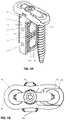
- FIG. 1is a perspective view of the lateral plate of the present invention with the moveable washer.
- FIG. 2is a top plan view of the lateral plate taken from FIG. 1 .
- FIG. 3is an exploded view of the spinal implant device with the lateral plate and moveable washer and the anti-back out mechanism and two bone screws and an implant body or cage made according to one embodiment of the present invention.
- FIG. 4Ais a perspective view of the assembly of the spinal implant of FIG. 3 .
- FIG. 4Bis a top view of the spinal implant taken from FIG. 4A .
- FIGS. 5A-5Care cross sectional views of the lateral plate assembly and the two bone screws.
- FIG. 5Ashowing negative inclinations.
- FIG. 5Bshowing positive inclinations, views 5 A and 5 B both having flush screw heads.
- FIG. 5Cshowing maximum inclinations with projecting screw heads.
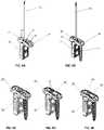
- FIGS. 6A-6Eshow sequential steps of implantation and fixation methodology of the spinal implant of the present invention utilizing a rod and a guide.
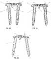
- FIGS. 7A-7Fare various views of the lateral plate assembly of a first embodiment.
- FIG. 7Ais a bottom plan view of the lateral plate assembly of the present invention without an implant body.
- FIG. 7Bis an end plan view showing a close end portion of the lateral plate assembly.
- FIG. 7Cis a side plan view.
- FIG. 7Dis the opposite end view showing the moveable washer.
- FIG. 7Eis a top plan view.
- FIG. 7Fis a top perspective view.
- FIG. 8is a perspective exemplary view of the lateral plate assembly shown affixed to a portion of a spine.
- a lateral plate assembly 10is illustrated in FIGS. 1, 2, 3, 5A -C, 7 A-F.
- the lateral plate assembly 10includes an elongated lateral plate 20 and a moveable washer 40 , as illustrated in FIGS. 1 and 2 and in the exploded view of FIG. 3 .
- This elongated lateral plate 20is for attachment to adjacent vertebrae 2 , 4 as illustrated in FIG. 8 .
- the lateral plate 20has a first end portion 21 and a second end portion 22 .
- Each end portion 21 , 22has an aperture for receiving a bone screw.
- the first aperture 30is a circular opening 30 that can be hemispherical or frustoconical for receiving the head 61 of a bone screw 60 positioned in the first end portion 21 .
- the second end portion 22has the second aperture which is a slotted opening 32 for receiving the second bone screw 62 as illustrated.
- the slotted opening 32extends from the second end portion 22 which has an open end 23 with channeled internal grooves 25 and overhanging lips 26 for receiving and holding a moveable washer 40 on top of the slotted opening 32 .
- the washer 40fits into channels or grooves 25 cut into the plate 20 while overhanging lips 26 hold the washer in place.
- This washer 40is configured to move along the length L above the slotted opening 32 .
- the moveable washer 40has an opening 42 for receiving a head 61 of bone screw 62 .
- This opening 42can be made similar to that of the frustoconical opening 30 of the opposite end of the lateral plate 20 and may have a similar frustoconical or hemispherical configuration adapted to receive a polyaxial screw that it can be angulated.
- the slotted opening 32allows the washer 40 to move along the length L such that it can increase or decrease the distance between the locations of the respective screw heads 61 of the screws 60 , 62 .
- This ability to move the screw heads 61 along the length of the elongated lateral plate 20enables the surgeon to ideally locate the screws 60 , 62 relative to the bone structure which he intends to drive the bone screws into and in so doing he can adjust or vary the compressive alignment forces on the vertebral bodies.
- This aperture 34is threaded and will be discussed later as a means for attaching the bone plate either to a spinal implant body and also to secure an anti-back out mechanism which will be discussed hereinafter.
- the elongated lateral plate 20has a thickness t and, as illustrated in FIG. 2 , has a maximum width W at the open end of the lateral plate 20 .
- a slot or recess 29is formed along each side of the lateral plate 20 to hold onto the plate 20 with a forceps or similar device.
- This additional componentis a spinal implant body or cage 50 .
- This implant body 50can be used with the lateral plate assembly 10 in such a fashion that the lateral plate 20 can be secured to this implant body 50 .
- Above the lateral plate 20 and washer 40is shown the pair of bone screws 60 and 62 .
- the bone screws 60 , 62have heads 61 adapted to fit in the apertures or openings 30 , 32 .
- Each bone screw 60 , 62has a shank 63 that is threaded. As shown, these bone screws 60 , 62 also have cutting flutes 65 that enable penetration into the bone as the bone screw is being threaded into bone.
- the heads 61 of the bone screws 60 , 62have fastening apertures 64 to allow a tool to be inserted to provide torsional forces to drive the screw 60 or 62 into position into the bones.
- the anti-back out mechanism 80includes a locking tab 82 having projecting ears 86 and 87 .
- the ear 86being elongated. This ear 86 will fit over the washer 40 and the slotted opening 32 as seen in the exploded view.
- a center aperture 88is provided into which a screw 84 can be inserted. This screw 84 is held in place by the use of a snap ring 85 to complete the mechanism 80 .
- this screw 84includes an opening 89 into which a fastener 90 can be provided.
- the fastener 90when tightened secures the plate assembly to the implant body 50 . This is best illustrated in FIGS. 5A-C and also all the FIGS. 7A-7F .
- an important aspect of the inventionis that the apertures 30 , 32 and opening 42 allow the heads 61 of the screws 60 , 62 to be angulated relative to a vertical plane.
- This angulation ⁇can have the bone screws 60 , 62 tilted inwardly relative to the plate such that a ⁇ 2 degree inclination can be achieved where the points of the screws 60 , 62 are directed towards each as illustrated in FIG. 5A .
- the screws 60 , 62alternatively can be angulated on a positive angle ⁇ . This angle of inclination can achieve up to 5 degrees wherein the points are directed outwardly.
- the heads 61 of the bone screw 60 , 62 as illustratedremain flush with the elongated plate 20 such that they do not protrude above the plate 20 at any portion of the plate.
- the objective or goalis to keep the bone plate 20 as flush as possible against the vertebrae into which it is to be attached.
- the plate 20can have a thickness of 5 mm to 3 mm, preferably about 4 mm.
- the positive inclinationcan actually be extended so that each screw 60 , 62 can be inclined as much as 15 degrees in the positive direction.
- FIG. 7Aa bottom view of the bone screws 60 , 62 is illustrated having been inserted and inclined in a positive inclination with regard to the vertical direction.
- the serrations 27for biting into the vertebral body and preventing any slippage against the vertebral bodies once the bone screws 60 , 62 are properly affixed.
- FIG. 7Ba closed end 21 of the lateral plate 20 is shown where the bone screws 60 , 62 are facing vertically downwardly.
- FIG. 7Ca side view is shown wherein the fastener 90 is shown projecting downwardly and the anti-back out mechanism 80 is shown properly positioned over the tops of the screws 60 , 62 .
- FIG. 7Aa bottom view of the bone screws 60 , 62 is illustrated having been inserted and inclined in a positive inclination with regard to the vertical direction.
- the serrations 27for biting into the vertebral body and preventing any slippage against the vertebral bodies once the bone screws 60 , 62 are properly affixed
- FIG. 7Dshows an opposite end 22 view showing the open end 23 exposing the moveable washer 40 so that it can be seen in its secured and locked position under the anti-back out mechanism 80 .
- FIG. 7Eshows a top view with the anti-back out mechanism 80 shown partially extending over the heads 61 of the screws 60 , 62 ; this prevents the screws from backing out as previously discussed.
- FIG. 7Fshows a perspective view of this embodiment.
- the lateral plate assemblyis combined with an implant body or cage 50 to form a system 100 which is illustrated in FIG. 3 in the exploded view and FIGS. 4A, 4B and FIGS. 6A-6E .
- the implant body or cage 50is illustrated.
- This implant body 50is for insertion between the adjacent vertebral bodies 2 and 4 .
- the body 50has an upper loading support surface 52 and a lower supporting surface 54 spaced by walls including a pair of opposing side walls 51 , 53 and a proximal end wall 55 and a distal end wall 57 .
- the proximal end wall 55has a threaded aperture 56 .
- between the wallscan be cavities or spaces 59 as illustrated.
- These spaces 59can allow for autograft material or allograft material to be positioned inside the implant body 50 to facilitate fusion of the implant body 50 to the adjacent vertebrae 2 , 4 .
- the supporting load surfaces 52 , 54can be faceted having a plurality of projections 58 for biting into the bone structure of the adjacent vertebrae 2 , 4 when implanted.
- the lateral plate 20can be an implantable metal such as titanium or stainless steel and the implant 50 can be a polymer like polyether ether ketone (PEEK) or its equivalent.
- FIG. 8To better understand how the present invention can be employed between two adjacent vertebrae using a lateral approach is shown in FIG. 8 .
- the assembly 10 when used with an implant body 50is illustrated. Initially, the surgeon will fasten the implant body 50 through the threaded aperture 56 and in doing so secures the implant body 50 firmly against the threaded rod 200 , as shown in FIG. 6A . At this point as shown in FIG. 6B , the two bone screws 60 and 62 can be dropped into the apertures 30 , 32 . Thereafter, the tab 82 can be positioned into the aperture in plate 20 . At this point the screw 84 contained in the anti-back out mechanism 80 can be locked into position. At this point, the assembly 100 is shown with the anti-back out mechanism 80 in position as shown in FIG.
- the fastener 90can be positioned as shown in FIG. 6E .
- the entire assembly 100is complete and the spinal implant system 100 can be properly positioned and secured to the vertebrae 2 , 4 as illustrated in FIG. 8 .
- the implant body 50is provided and spaced between the adjacent vertebrae 2 , 4 .
Landscapes
- Health & Medical Sciences (AREA)
- Orthopedic Medicine & Surgery (AREA)
- Engineering & Computer Science (AREA)
- Biomedical Technology (AREA)
- Neurology (AREA)
- Life Sciences & Earth Sciences (AREA)
- Surgery (AREA)
- General Health & Medical Sciences (AREA)
- Veterinary Medicine (AREA)
- Heart & Thoracic Surgery (AREA)
- Public Health (AREA)
- Animal Behavior & Ethology (AREA)
- Nuclear Medicine, Radiotherapy & Molecular Imaging (AREA)
- Medical Informatics (AREA)
- Molecular Biology (AREA)
- Vascular Medicine (AREA)
- Transplantation (AREA)
- Oral & Maxillofacial Surgery (AREA)
- Cardiology (AREA)
- Prostheses (AREA)
- Surgical Instruments (AREA)
Abstract
Description
Claims (10)
Priority Applications (2)
| Application Number | Priority Date | Filing Date | Title |
|---|---|---|---|
| US16/444,979US11304820B2 (en) | 2015-02-23 | 2019-06-18 | Lateral plate and spinal implant system and method |
| US17/693,806US20220202587A1 (en) | 2015-02-23 | 2022-03-14 | Lateral plate and spinal implant system and method |
Applications Claiming Priority (3)
| Application Number | Priority Date | Filing Date | Title |
|---|---|---|---|
| US201562119406P | 2015-02-23 | 2015-02-23 | |
| US15/049,434US10363145B2 (en) | 2015-02-23 | 2016-02-22 | Lateral plate and spinal implant system and method |
| US16/444,979US11304820B2 (en) | 2015-02-23 | 2019-06-18 | Lateral plate and spinal implant system and method |
Related Parent Applications (1)
| Application Number | Title | Priority Date | Filing Date |
|---|---|---|---|
| US15/049,434ContinuationUS10363145B2 (en) | 2015-02-23 | 2016-02-22 | Lateral plate and spinal implant system and method |
Related Child Applications (1)
| Application Number | Title | Priority Date | Filing Date |
|---|---|---|---|
| US17/693,806ContinuationUS20220202587A1 (en) | 2015-02-23 | 2022-03-14 | Lateral plate and spinal implant system and method |
Publications (2)
| Publication Number | Publication Date |
|---|---|
| US20190298541A1 US20190298541A1 (en) | 2019-10-03 |
| US11304820B2true US11304820B2 (en) | 2022-04-19 |
Family
ID=56692923
Family Applications (3)
| Application Number | Title | Priority Date | Filing Date |
|---|---|---|---|
| US15/049,434Active2037-11-13US10363145B2 (en) | 2015-02-23 | 2016-02-22 | Lateral plate and spinal implant system and method |
| US16/444,979ActiveUS11304820B2 (en) | 2015-02-23 | 2019-06-18 | Lateral plate and spinal implant system and method |
| US17/693,806AbandonedUS20220202587A1 (en) | 2015-02-23 | 2022-03-14 | Lateral plate and spinal implant system and method |
Family Applications Before (1)
| Application Number | Title | Priority Date | Filing Date |
|---|---|---|---|
| US15/049,434Active2037-11-13US10363145B2 (en) | 2015-02-23 | 2016-02-22 | Lateral plate and spinal implant system and method |
Family Applications After (1)
| Application Number | Title | Priority Date | Filing Date |
|---|---|---|---|
| US17/693,806AbandonedUS20220202587A1 (en) | 2015-02-23 | 2022-03-14 | Lateral plate and spinal implant system and method |
Country Status (1)
| Country | Link |
|---|---|
| US (3) | US10363145B2 (en) |
Families Citing this family (6)
| Publication number | Priority date | Publication date | Assignee | Title |
|---|---|---|---|---|
| US10076364B2 (en) | 2012-06-29 | 2018-09-18 | K2M, Inc. | Minimal-profile anterior cervical plate and cage apparatus and method of using same |
| US9987145B2 (en)* | 2015-10-01 | 2018-06-05 | Seth Kevin WILLIAMS | Lateral block plate |
| EP4108194A1 (en) | 2018-03-02 | 2022-12-28 | Stryker European Holdings I, LLC | Bone plates and associated screws |
| US20200253645A1 (en)* | 2019-02-11 | 2020-08-13 | Nexus Spine, LLC | Press-Fit Anterior Cervical Plate |
| US11406511B2 (en) | 2020-08-24 | 2022-08-09 | Seth K. WILLIAMS | Lateral spine plate with lateral spine cage anchoring system |
| CN112773578B (en)* | 2021-02-09 | 2022-08-16 | 北京爱康宜诚医疗器材有限公司 | Lumbar vertebra fusion cage |
Citations (13)
| Publication number | Priority date | Publication date | Assignee | Title |
|---|---|---|---|---|
| US5487743A (en)* | 1994-02-15 | 1996-01-30 | Sofamore, S.N.C. | Anterior dorso-lumbar spinal osteosynthesis instrumentation for the correction of kyphosis |
| US6235034B1 (en) | 1997-10-24 | 2001-05-22 | Robert S. Bray | Bone plate and bone screw guide mechanism |
| US6413259B1 (en) | 2000-12-14 | 2002-07-02 | Blackstone Medical, Inc | Bone plate assembly including a screw retaining member |
| US20020111630A1 (en)* | 2001-02-15 | 2002-08-15 | Ralph James D. | Longitudinal plate assembly having an adjustable length |
| US7452370B2 (en) | 2005-04-29 | 2008-11-18 | Warsaw Orthopedic, Inc | Apparatus for retaining a bone anchor in a bone plate and method for use thereof |
| US7740630B2 (en)* | 2001-06-04 | 2010-06-22 | Warsaw Orthopedic, Inc. | Anterior cervical plate system having vertebral body engaging anchors and connecting plate |
| US8273127B2 (en) | 2007-06-06 | 2012-09-25 | Spinesmith Partners, L.P. | Interbody fusion device and associated methods |
| US20120277873A1 (en) | 2007-06-06 | 2012-11-01 | Richard Kana | Interbody fusion device with lipped anterior plate and associated methods |
| US8348982B2 (en) | 2003-04-21 | 2013-01-08 | Atlas Spine, Inc. | Bone fixation plate |
| US8419776B2 (en)* | 2010-03-08 | 2013-04-16 | Memometal Technologies | Radius-plate assembly |
| US8623019B2 (en)* | 2007-07-03 | 2014-01-07 | Pioneer Surgical Technology, Inc. | Bone plate system |
| US20140012380A1 (en) | 2012-06-29 | 2014-01-09 | DuPuy Synthes Products, LLC | Lateral insertion spinal implant |
| US8709085B2 (en) | 2003-02-06 | 2014-04-29 | DePuy Synthes Products, LLC | Intervertebral implant |
Family Cites Families (1)
| Publication number | Priority date | Publication date | Assignee | Title |
|---|---|---|---|---|
| RU2012157129A (en)* | 2010-06-08 | 2014-07-20 | Смит Энд Нефью, Инк. | IMPLANT AND METHODS OF ITS MANUFACTURE |
- 2016
- 2016-02-22USUS15/049,434patent/US10363145B2/enactiveActive
- 2019
- 2019-06-18USUS16/444,979patent/US11304820B2/enactiveActive
- 2022
- 2022-03-14USUS17/693,806patent/US20220202587A1/ennot_activeAbandoned
Patent Citations (15)
| Publication number | Priority date | Publication date | Assignee | Title |
|---|---|---|---|---|
| US5487743A (en)* | 1994-02-15 | 1996-01-30 | Sofamore, S.N.C. | Anterior dorso-lumbar spinal osteosynthesis instrumentation for the correction of kyphosis |
| US6235034B1 (en) | 1997-10-24 | 2001-05-22 | Robert S. Bray | Bone plate and bone screw guide mechanism |
| US6413259B1 (en) | 2000-12-14 | 2002-07-02 | Blackstone Medical, Inc | Bone plate assembly including a screw retaining member |
| US20020111630A1 (en)* | 2001-02-15 | 2002-08-15 | Ralph James D. | Longitudinal plate assembly having an adjustable length |
| US7740630B2 (en)* | 2001-06-04 | 2010-06-22 | Warsaw Orthopedic, Inc. | Anterior cervical plate system having vertebral body engaging anchors and connecting plate |
| US8709085B2 (en) | 2003-02-06 | 2014-04-29 | DePuy Synthes Products, LLC | Intervertebral implant |
| US9463097B2 (en)* | 2003-02-06 | 2016-10-11 | DePuy Synthes Products, Inc. | Intervertebral implant |
| US8348982B2 (en) | 2003-04-21 | 2013-01-08 | Atlas Spine, Inc. | Bone fixation plate |
| US7452370B2 (en) | 2005-04-29 | 2008-11-18 | Warsaw Orthopedic, Inc | Apparatus for retaining a bone anchor in a bone plate and method for use thereof |
| US8273127B2 (en) | 2007-06-06 | 2012-09-25 | Spinesmith Partners, L.P. | Interbody fusion device and associated methods |
| US20120277873A1 (en) | 2007-06-06 | 2012-11-01 | Richard Kana | Interbody fusion device with lipped anterior plate and associated methods |
| US8623019B2 (en)* | 2007-07-03 | 2014-01-07 | Pioneer Surgical Technology, Inc. | Bone plate system |
| US8419776B2 (en)* | 2010-03-08 | 2013-04-16 | Memometal Technologies | Radius-plate assembly |
| US20140012380A1 (en) | 2012-06-29 | 2014-01-09 | DuPuy Synthes Products, LLC | Lateral insertion spinal implant |
| US9943417B2 (en)* | 2012-06-29 | 2018-04-17 | DePuy Synthes Products, Inc. | Lateral insertion spinal implant |
Also Published As
| Publication number | Publication date |
|---|---|
| US20190298541A1 (en) | 2019-10-03 |
| US20160242925A1 (en) | 2016-08-25 |
| US10363145B2 (en) | 2019-07-30 |
| US20220202587A1 (en) | 2022-06-30 |
Similar Documents
| Publication | Publication Date | Title |
|---|---|---|
| US20220202587A1 (en) | Lateral plate and spinal implant system and method | |
| US10492836B2 (en) | Anterior cervical plate | |
| US8845737B2 (en) | Interbody spinal implants with extravertebral support plates | |
| US9023052B2 (en) | Ulna osteotomy system | |
| US7608096B2 (en) | Posterior pedicle screw and plate system and methods | |
| US7914561B2 (en) | Resilient bone plate and screw system allowing bi-directional assembly | |
| US8012188B2 (en) | Spinal implants and methods with extended multi-axial anchor assemblies | |
| US6984234B2 (en) | Bone plate stabilization system and method for its use | |
| US20100049256A1 (en) | Anterior cerivcal plating system | |
| AU2011310548B2 (en) | Lamina implant set | |
| US20060106387A1 (en) | Spinal plate system and method of use | |
| US20130060294A1 (en) | Bone Implants | |
| CN101528141A (en) | Orthopedic implant assembly | |
| US9743959B2 (en) | Low profile spinal fixation system | |
| US10751100B2 (en) | Bone screws and surgical sets comprising bone screws | |
| EP4088675B1 (en) | Top loading quick lock construct | |
| US20110028975A1 (en) | Clivus plate | |
| US20140257390A1 (en) | Osseointegrative Spinal Fixation Implants |
Legal Events
| Date | Code | Title | Description |
|---|---|---|---|
| FEPP | Fee payment procedure | Free format text:ENTITY STATUS SET TO UNDISCOUNTED (ORIGINAL EVENT CODE: BIG.); ENTITY STATUS OF PATENT OWNER: SMALL ENTITY | |
| FEPP | Fee payment procedure | Free format text:ENTITY STATUS SET TO SMALL (ORIGINAL EVENT CODE: SMAL); ENTITY STATUS OF PATENT OWNER: SMALL ENTITY | |
| STPP | Information on status: patent application and granting procedure in general | Free format text:DOCKETED NEW CASE - READY FOR EXAMINATION | |
| AS | Assignment | Owner name:SPINAL ELEMENTS, INC., CALIFORNIA Free format text:MERGER AND CHANGE OF NAME;ASSIGNORS:SPINAL ELEMENTS, INC.;AMENDIA, INC.;REEL/FRAME:052024/0805 Effective date:20191231 | |
| STPP | Information on status: patent application and granting procedure in general | Free format text:RESPONSE TO NON-FINAL OFFICE ACTION ENTERED AND FORWARDED TO EXAMINER | |
| STPP | Information on status: patent application and granting procedure in general | Free format text:FINAL REJECTION MAILED | |
| STPP | Information on status: patent application and granting procedure in general | Free format text:DOCKETED NEW CASE - READY FOR EXAMINATION | |
| STPP | Information on status: patent application and granting procedure in general | Free format text:NOTICE OF ALLOWANCE MAILED -- APPLICATION RECEIVED IN OFFICE OF PUBLICATIONS | |
| STPP | Information on status: patent application and granting procedure in general | Free format text:AWAITING TC RESP., ISSUE FEE NOT PAID | |
| STPP | Information on status: patent application and granting procedure in general | Free format text:NOTICE OF ALLOWANCE MAILED -- APPLICATION RECEIVED IN OFFICE OF PUBLICATIONS | |
| STPP | Information on status: patent application and granting procedure in general | Free format text:PUBLICATIONS -- ISSUE FEE PAYMENT VERIFIED | |
| STCF | Information on status: patent grant | Free format text:PATENTED CASE | |
| AS | Assignment | Owner name:PERCEPTIVE CREDIT HOLDINGS IV, LP, NEW YORK Free format text:SECURITY INTEREST;ASSIGNORS:SPINAL ELEMENTS, INC.;CUSTOM SPINE ACQUISITION, INC.;OMNI ACQUISITION INC.;REEL/FRAME:067596/0295 Effective date:20240531 |