US11304804B2 - Prosthetic valve with connecting struts of variable size and tissue anchoring legs of variable size that extend from junctions - Google Patents
Prosthetic valve with connecting struts of variable size and tissue anchoring legs of variable size that extend from junctionsDownload PDFInfo
- Publication number
- US11304804B2 US11304804B2US16/135,599US201816135599AUS11304804B2US 11304804 B2US11304804 B2US 11304804B2US 201816135599 AUS201816135599 AUS 201816135599AUS 11304804 B2US11304804 B2US 11304804B2
- Authority
- US
- United States
- Prior art keywords
- tissue anchoring
- atrial
- leg
- valve
- anchoring leg
- Prior art date
- Legal status (The legal status is an assumption and is not a legal conclusion. Google has not performed a legal analysis and makes no representation as to the accuracy of the status listed.)
- Active
Links
Images


Classifications
- A—HUMAN NECESSITIES
- A61—MEDICAL OR VETERINARY SCIENCE; HYGIENE
- A61F—FILTERS IMPLANTABLE INTO BLOOD VESSELS; PROSTHESES; DEVICES PROVIDING PATENCY TO, OR PREVENTING COLLAPSING OF, TUBULAR STRUCTURES OF THE BODY, e.g. STENTS; ORTHOPAEDIC, NURSING OR CONTRACEPTIVE DEVICES; FOMENTATION; TREATMENT OR PROTECTION OF EYES OR EARS; BANDAGES, DRESSINGS OR ABSORBENT PADS; FIRST-AID KITS
- A61F2/00—Filters implantable into blood vessels; Prostheses, i.e. artificial substitutes or replacements for parts of the body; Appliances for connecting them with the body; Devices providing patency to, or preventing collapsing of, tubular structures of the body, e.g. stents
- A61F2/02—Prostheses implantable into the body
- A61F2/24—Heart valves ; Vascular valves, e.g. venous valves; Heart implants, e.g. passive devices for improving the function of the native valve or the heart muscle; Transmyocardial revascularisation [TMR] devices; Valves implantable in the body
- A61F2/2427—Devices for manipulating or deploying heart valves during implantation
- A61F2/243—Deployment by mechanical expansion
- A—HUMAN NECESSITIES
- A61—MEDICAL OR VETERINARY SCIENCE; HYGIENE
- A61F—FILTERS IMPLANTABLE INTO BLOOD VESSELS; PROSTHESES; DEVICES PROVIDING PATENCY TO, OR PREVENTING COLLAPSING OF, TUBULAR STRUCTURES OF THE BODY, e.g. STENTS; ORTHOPAEDIC, NURSING OR CONTRACEPTIVE DEVICES; FOMENTATION; TREATMENT OR PROTECTION OF EYES OR EARS; BANDAGES, DRESSINGS OR ABSORBENT PADS; FIRST-AID KITS
- A61F2/00—Filters implantable into blood vessels; Prostheses, i.e. artificial substitutes or replacements for parts of the body; Appliances for connecting them with the body; Devices providing patency to, or preventing collapsing of, tubular structures of the body, e.g. stents
- A61F2/02—Prostheses implantable into the body
- A61F2/24—Heart valves ; Vascular valves, e.g. venous valves; Heart implants, e.g. passive devices for improving the function of the native valve or the heart muscle; Transmyocardial revascularisation [TMR] devices; Valves implantable in the body
- A61F2/2427—Devices for manipulating or deploying heart valves during implantation
- A61F2/2436—Deployment by retracting a sheath
- A—HUMAN NECESSITIES
- A61—MEDICAL OR VETERINARY SCIENCE; HYGIENE
- A61F—FILTERS IMPLANTABLE INTO BLOOD VESSELS; PROSTHESES; DEVICES PROVIDING PATENCY TO, OR PREVENTING COLLAPSING OF, TUBULAR STRUCTURES OF THE BODY, e.g. STENTS; ORTHOPAEDIC, NURSING OR CONTRACEPTIVE DEVICES; FOMENTATION; TREATMENT OR PROTECTION OF EYES OR EARS; BANDAGES, DRESSINGS OR ABSORBENT PADS; FIRST-AID KITS
- A61F2/00—Filters implantable into blood vessels; Prostheses, i.e. artificial substitutes or replacements for parts of the body; Appliances for connecting them with the body; Devices providing patency to, or preventing collapsing of, tubular structures of the body, e.g. stents
- A61F2/02—Prostheses implantable into the body
- A61F2/24—Heart valves ; Vascular valves, e.g. venous valves; Heart implants, e.g. passive devices for improving the function of the native valve or the heart muscle; Transmyocardial revascularisation [TMR] devices; Valves implantable in the body
- A61F2/2442—Annuloplasty rings or inserts for correcting the valve shape; Implants for improving the function of a native heart valve
- A61F2/2445—Annuloplasty rings in direct contact with the valve annulus
- A—HUMAN NECESSITIES
- A61—MEDICAL OR VETERINARY SCIENCE; HYGIENE
- A61F—FILTERS IMPLANTABLE INTO BLOOD VESSELS; PROSTHESES; DEVICES PROVIDING PATENCY TO, OR PREVENTING COLLAPSING OF, TUBULAR STRUCTURES OF THE BODY, e.g. STENTS; ORTHOPAEDIC, NURSING OR CONTRACEPTIVE DEVICES; FOMENTATION; TREATMENT OR PROTECTION OF EYES OR EARS; BANDAGES, DRESSINGS OR ABSORBENT PADS; FIRST-AID KITS
- A61F2/00—Filters implantable into blood vessels; Prostheses, i.e. artificial substitutes or replacements for parts of the body; Appliances for connecting them with the body; Devices providing patency to, or preventing collapsing of, tubular structures of the body, e.g. stents
- A61F2/02—Prostheses implantable into the body
- A61F2/24—Heart valves ; Vascular valves, e.g. venous valves; Heart implants, e.g. passive devices for improving the function of the native valve or the heart muscle; Transmyocardial revascularisation [TMR] devices; Valves implantable in the body
- A61F2/2442—Annuloplasty rings or inserts for correcting the valve shape; Implants for improving the function of a native heart valve
- A61F2/2454—Means for preventing inversion of the valve leaflets, e.g. chordae tendineae prostheses
- A—HUMAN NECESSITIES
- A61—MEDICAL OR VETERINARY SCIENCE; HYGIENE
- A61F—FILTERS IMPLANTABLE INTO BLOOD VESSELS; PROSTHESES; DEVICES PROVIDING PATENCY TO, OR PREVENTING COLLAPSING OF, TUBULAR STRUCTURES OF THE BODY, e.g. STENTS; ORTHOPAEDIC, NURSING OR CONTRACEPTIVE DEVICES; FOMENTATION; TREATMENT OR PROTECTION OF EYES OR EARS; BANDAGES, DRESSINGS OR ABSORBENT PADS; FIRST-AID KITS
- A61F2/00—Filters implantable into blood vessels; Prostheses, i.e. artificial substitutes or replacements for parts of the body; Appliances for connecting them with the body; Devices providing patency to, or preventing collapsing of, tubular structures of the body, e.g. stents
- A61F2/02—Prostheses implantable into the body
- A61F2/24—Heart valves ; Vascular valves, e.g. venous valves; Heart implants, e.g. passive devices for improving the function of the native valve or the heart muscle; Transmyocardial revascularisation [TMR] devices; Valves implantable in the body
- A61F2/2442—Annuloplasty rings or inserts for correcting the valve shape; Implants for improving the function of a native heart valve
- A61F2/2463—Implants forming part of the valve leaflets
- A—HUMAN NECESSITIES
- A61—MEDICAL OR VETERINARY SCIENCE; HYGIENE
- A61F—FILTERS IMPLANTABLE INTO BLOOD VESSELS; PROSTHESES; DEVICES PROVIDING PATENCY TO, OR PREVENTING COLLAPSING OF, TUBULAR STRUCTURES OF THE BODY, e.g. STENTS; ORTHOPAEDIC, NURSING OR CONTRACEPTIVE DEVICES; FOMENTATION; TREATMENT OR PROTECTION OF EYES OR EARS; BANDAGES, DRESSINGS OR ABSORBENT PADS; FIRST-AID KITS
- A61F2/00—Filters implantable into blood vessels; Prostheses, i.e. artificial substitutes or replacements for parts of the body; Appliances for connecting them with the body; Devices providing patency to, or preventing collapsing of, tubular structures of the body, e.g. stents
- A61F2/02—Prostheses implantable into the body
- A61F2/24—Heart valves ; Vascular valves, e.g. venous valves; Heart implants, e.g. passive devices for improving the function of the native valve or the heart muscle; Transmyocardial revascularisation [TMR] devices; Valves implantable in the body
- A61F2/2409—Support rings therefor, e.g. for connecting valves to tissue
- A—HUMAN NECESSITIES
- A61—MEDICAL OR VETERINARY SCIENCE; HYGIENE
- A61F—FILTERS IMPLANTABLE INTO BLOOD VESSELS; PROSTHESES; DEVICES PROVIDING PATENCY TO, OR PREVENTING COLLAPSING OF, TUBULAR STRUCTURES OF THE BODY, e.g. STENTS; ORTHOPAEDIC, NURSING OR CONTRACEPTIVE DEVICES; FOMENTATION; TREATMENT OR PROTECTION OF EYES OR EARS; BANDAGES, DRESSINGS OR ABSORBENT PADS; FIRST-AID KITS
- A61F2/00—Filters implantable into blood vessels; Prostheses, i.e. artificial substitutes or replacements for parts of the body; Appliances for connecting them with the body; Devices providing patency to, or preventing collapsing of, tubular structures of the body, e.g. stents
- A61F2/02—Prostheses implantable into the body
- A61F2/24—Heart valves ; Vascular valves, e.g. venous valves; Heart implants, e.g. passive devices for improving the function of the native valve or the heart muscle; Transmyocardial revascularisation [TMR] devices; Valves implantable in the body
- A61F2/2412—Heart valves ; Vascular valves, e.g. venous valves; Heart implants, e.g. passive devices for improving the function of the native valve or the heart muscle; Transmyocardial revascularisation [TMR] devices; Valves implantable in the body with soft flexible valve members, e.g. tissue valves shaped like natural valves
- A61F2/2418—Scaffolds therefor, e.g. support stents
- A—HUMAN NECESSITIES
- A61—MEDICAL OR VETERINARY SCIENCE; HYGIENE
- A61F—FILTERS IMPLANTABLE INTO BLOOD VESSELS; PROSTHESES; DEVICES PROVIDING PATENCY TO, OR PREVENTING COLLAPSING OF, TUBULAR STRUCTURES OF THE BODY, e.g. STENTS; ORTHOPAEDIC, NURSING OR CONTRACEPTIVE DEVICES; FOMENTATION; TREATMENT OR PROTECTION OF EYES OR EARS; BANDAGES, DRESSINGS OR ABSORBENT PADS; FIRST-AID KITS
- A61F2/00—Filters implantable into blood vessels; Prostheses, i.e. artificial substitutes or replacements for parts of the body; Appliances for connecting them with the body; Devices providing patency to, or preventing collapsing of, tubular structures of the body, e.g. stents
- A61F2/02—Prostheses implantable into the body
- A61F2/24—Heart valves ; Vascular valves, e.g. venous valves; Heart implants, e.g. passive devices for improving the function of the native valve or the heart muscle; Transmyocardial revascularisation [TMR] devices; Valves implantable in the body
- A61F2/2442—Annuloplasty rings or inserts for correcting the valve shape; Implants for improving the function of a native heart valve
- A61F2/246—Devices for obstructing a leak through a native valve in a closed condition
- A—HUMAN NECESSITIES
- A61—MEDICAL OR VETERINARY SCIENCE; HYGIENE
- A61F—FILTERS IMPLANTABLE INTO BLOOD VESSELS; PROSTHESES; DEVICES PROVIDING PATENCY TO, OR PREVENTING COLLAPSING OF, TUBULAR STRUCTURES OF THE BODY, e.g. STENTS; ORTHOPAEDIC, NURSING OR CONTRACEPTIVE DEVICES; FOMENTATION; TREATMENT OR PROTECTION OF EYES OR EARS; BANDAGES, DRESSINGS OR ABSORBENT PADS; FIRST-AID KITS
- A61F2/00—Filters implantable into blood vessels; Prostheses, i.e. artificial substitutes or replacements for parts of the body; Appliances for connecting them with the body; Devices providing patency to, or preventing collapsing of, tubular structures of the body, e.g. stents
- A61F2/02—Prostheses implantable into the body
- A61F2/24—Heart valves ; Vascular valves, e.g. venous valves; Heart implants, e.g. passive devices for improving the function of the native valve or the heart muscle; Transmyocardial revascularisation [TMR] devices; Valves implantable in the body
- A61F2/2442—Annuloplasty rings or inserts for correcting the valve shape; Implants for improving the function of a native heart valve
- A61F2/2466—Delivery devices therefor
- A—HUMAN NECESSITIES
- A61—MEDICAL OR VETERINARY SCIENCE; HYGIENE
- A61F—FILTERS IMPLANTABLE INTO BLOOD VESSELS; PROSTHESES; DEVICES PROVIDING PATENCY TO, OR PREVENTING COLLAPSING OF, TUBULAR STRUCTURES OF THE BODY, e.g. STENTS; ORTHOPAEDIC, NURSING OR CONTRACEPTIVE DEVICES; FOMENTATION; TREATMENT OR PROTECTION OF EYES OR EARS; BANDAGES, DRESSINGS OR ABSORBENT PADS; FIRST-AID KITS
- A61F2210/00—Particular material properties of prostheses classified in groups A61F2/00 - A61F2/26 or A61F2/82 or A61F9/00 or A61F11/00 or subgroups thereof
- A61F2210/0014—Particular material properties of prostheses classified in groups A61F2/00 - A61F2/26 or A61F2/82 or A61F9/00 or A61F11/00 or subgroups thereof using shape memory or superelastic materials, e.g. nitinol
- A—HUMAN NECESSITIES
- A61—MEDICAL OR VETERINARY SCIENCE; HYGIENE
- A61F—FILTERS IMPLANTABLE INTO BLOOD VESSELS; PROSTHESES; DEVICES PROVIDING PATENCY TO, OR PREVENTING COLLAPSING OF, TUBULAR STRUCTURES OF THE BODY, e.g. STENTS; ORTHOPAEDIC, NURSING OR CONTRACEPTIVE DEVICES; FOMENTATION; TREATMENT OR PROTECTION OF EYES OR EARS; BANDAGES, DRESSINGS OR ABSORBENT PADS; FIRST-AID KITS
- A61F2220/00—Fixations or connections for prostheses classified in groups A61F2/00 - A61F2/26 or A61F2/82 or A61F9/00 or A61F11/00 or subgroups thereof
- A61F2220/0008—Fixation appliances for connecting prostheses to the body
- A—HUMAN NECESSITIES
- A61—MEDICAL OR VETERINARY SCIENCE; HYGIENE
- A61F—FILTERS IMPLANTABLE INTO BLOOD VESSELS; PROSTHESES; DEVICES PROVIDING PATENCY TO, OR PREVENTING COLLAPSING OF, TUBULAR STRUCTURES OF THE BODY, e.g. STENTS; ORTHOPAEDIC, NURSING OR CONTRACEPTIVE DEVICES; FOMENTATION; TREATMENT OR PROTECTION OF EYES OR EARS; BANDAGES, DRESSINGS OR ABSORBENT PADS; FIRST-AID KITS
- A61F2250/00—Special features of prostheses classified in groups A61F2/00 - A61F2/26 or A61F2/82 or A61F9/00 or A61F11/00 or subgroups thereof
- A61F2250/0058—Additional features; Implant or prostheses properties not otherwise provided for
- A61F2250/0069—Sealing means
- A61F2250/007—O-rings
Definitions
- This disclosurerelates generally to prosthetic valves and delivery systems for prosthetic valves. More specifically, this disclosure relates to prosthetic heart valves and methods thereof.
- the native heart valves(the tricuspid valve, pulmonary valve, mitral valve, and aortic valve) play an important role in regulating flow of blood through the cardiovascular system.
- the native heart valvesmay become damaged or impaired due to, for example, cardiovascular diseases, infections, or congenital malformations, thus limiting the ability of the native heart valves to regulate blood flow. This deficiency may result in reduced cardiovascular function or even death.
- prosthetic heart valvesmay be implanted at or near the site of a damaged or impaired native valve.
- a prosthetic heart valvemay assist or replace the functionality of an impaired native valve, leading to better regulation of blood flow and improved cardiovascular function.
- many existing prosthetic heart valvesrequire implantation via an open heart procedure, which is highly-invasive and may cause life-threatening complications.
- Other prosthetic valvesmay be collapsed within a prosthetic valve delivery system and advanced into the heart, at which point the prosthetic valve may be removed from the delivery system and expanded at the native valve site.
- many of these prosthetic valvesare large in size and therefore difficult to deliver into the heart without causing damage to healthy tissue along the implantation route.
- prosthetic valvesmay be difficult to securely implant at the native valve site due to their complex structure and the limited maneuverability of existing prosthetic valve delivery systems within the heart.
- many prosthetic valvesare so large that they may protrude several centimeters into surrounding heart chambers once they are implanted, impairing cardiac filling and causing injury to the anatomy within the heart.
- prosthetic heart valvesthat are smaller in size but that are still configured to assist or replace the functionality of a diseased or damaged native heart valve.
- prosthetic heart valvesthat are more easily maneuvered into the heart and securely implanted at the site of a native heart valve.
- improved prosthetic heart valve delivery systemsthat are configured to securely implant a prosthetic heart valve at an implantation site.
- the present disclosureprovides prosthetic heart valves with a reduced axial length such that the prosthetic heart valves may be more easily delivered into the heart and may exhibit less protrusion into the chambers of the heart.
- the present disclosurealso provides improved prosthetic heart valve delivery systems and methods of implanting prosthetic heart valves, such that prosthetic heart valves may be securely anchored at the implantation site.
- the present disclosurediscloses prosthetic valves for implantation within a native mitral valve and methods for implanting prosthetic valves within a native mitral valve.
- Particular examples of the disclosuremay pertain to a prosthetic valve formed at least partially of struts having different cross-sectional areas.
- an expandable prosthetic valvefor implantation within a native mitral valve.
- the prosthetic valveincludes an expandable valve body having an atrial end, a ventricular end opposite the atrial end, and an intermediate portion extending between the atrial end and the ventricular end.
- the valve bodyincludes a plurality of struts intersecting at junctions.
- the prosthetic valveadditionally includes a plurality of tissue anchoring legs extending from junctions within the intermediate portion of the valve body. At least one of the tissue anchoring legs has a cross-sectional area that is larger by at least 20% than a cross-sectional area of a strut extending between the at least one tissue anchoring leg and an adjacent tissue anchoring leg.
- the cross-sectional area of the at least one tissue anchoring legis perpendicular to a direction of extension of the at least one tissue anchoring leg.
- the cross-sectional area of the strut extending between the at least one tissue anchoring leg and the adjacent tissue anchoring legis perpendicular to a direction of extension of the strut.
- the cross-sectional area of the at least one tissue anchoring legis at least four times larger than the cross-sectional area of the strut extending between the at least one tissue anchoring leg and the adjacent tissue anchoring leg.
- the at least one tissue anchoring legis configured to extend radially outward from the valve body and in a non-ventricular ventricular direction.
- the at least one tissue anchoring legis configured to engage ventricular tissue of the native mitral valve.
- the prosthetic valveadditionally includes a plurality of atrial tissue anchoring arms extending radially outward from junctions within the intermediate portion of the valve body. At least one atrial tissue anchoring arm is configured to extend from the valve body in an atrial direction. The at least one atrial tissue anchoring arm is configured to extend radially outward beyond a terminal end of the at least one tissue anchoring leg. A width of a radial outer surface of the at least one tissue anchoring leg is at least twice as large as a width of a radial outer surface of the strut extending between the at least one tissue anchoring leg and the adjacent tissue anchoring leg.
- the prosthetic valveadditionally includes a tissue anchoring leg base strut extending between the junction from which the at least one tissue anchoring leg extends and a ventricular end of the valve body.
- the tissue anchoring leg base struthas a cross-sectional area that is substantially equal to the cross-sectional area of the at least one tissue anchoring leg.
- the cross-sectional area of the at least one tissue anchoring legis situated within an inner radial half of the at least one tissue anchoring leg.
- the inner radial half of the at least one tissue anchoring leghas a substantially constant cross-sectional area.
- the prosthetic valveadditionally includes a second strut extending between the at least one tissue anchoring leg and the adjacent tissue anchoring leg.
- a junction between the strut and the second strutis situated in an axial direction relative to the junction from which the at least one tissue anchoring leg extends.
- a terminal end of the at least one tissue anchoring legis configured to be situated in an axial direction relative to the atrial end of the valve body.
- the at least one tissue anchoring leg and the adjacent tissue anchoring legdo not connect to the valve body at a common point of connection.
- the at least one tissue anchoring legextends from a single junction of the valve body. An entire length of the at least one tissue anchoring leg is configured to extend radially outward and toward an atrium upon implantation.
- an expandable prosthetic valvefor implantation within a native mitral valve.
- the prosthetic valveincludes an expandable annular outer frame including a plurality of struts intersecting at junctions to form closed cells.
- the annular outer framealso includes a plurality of ventricular tissue anchoring legs configured to extend radially outward from the junctions of the annular outer frame.
- the prosthetic valvealso includes an inner frame situated at least partially within the annular outer frame.
- the inner frameincludes a plurality of struts intersecting at junctions to form closed cells and a plurality of atrial tissue anchoring arms configured to extend radially outward from the junctions of the inner frame.
- At least one of the ventricular tissue anchoring legshas a cross-sectional area that is larger by at least 20% than a cross-sectional area of a strut extending between the at least one ventricular tissue anchoring leg and an adjacent ventricular tissue anchoring leg.
- At least one of the atrial tissue anchoring armshas a cross-sectional area that is larger by at least 20% than a cross-sectional area of a strut extending between the at least one atrial tissue anchoring arm and an adjacent atrial tissue anchoring arm. At least one of the atrial tissue anchoring arms has a cross-sectional area that is larger by at least 20% than a cross-sectional area of the strut extending between the at least one ventricular tissue anchoring leg and the adjacent ventricular tissue anchoring leg. At least one connection between the annular outer frame and the inner frame is positioned away from respective atrial ends of the annular outer frame and inner frame. At least one connection between the annular outer frame and the inner frame is positioned in a ventricular direction relative to at least one atrial tissue anchoring arm and to the at least one ventricular tissue anchoring leg.
- an expandable prosthetic valvefor implantation within a native mitral valve.
- the prosthetic valveincludes an expandable valve body including a plurality of struts intersecting at junctions.
- the prosthetic valvealso includes a plurality of tissue anchoring legs extending from the junctions of the valve body. At least one of the tissue anchoring legs has a cross-sectional area that is larger by at least 20% than a cross-sectional area of a first strut extending from the at least one tissue anchoring leg toward an adjacent tissue anchoring leg.
- the at least one tissue anchoring leg and the adjacent tissue anchoring legare angularly separated by a single junction.
- the at least one tissue anchoring legincludes an opening.
- the prosthetic valvealso includes a second strut extending from the adjacent tissue anchoring leg. The first strut and second strut meet at the single junction.
- the at least one tissue anchoring legincludes at least one bent portion.
- FIG. 1Aillustrates a front elevation view of an exemplary frame for a prosthetic valve, consistent with various embodiments of the present disclosure.
- FIG. 1Billustrates a perspective view of the exemplary frame of FIG. 1A , consistent with various embodiments of the present disclosure.
- FIG. 2Aillustrates a front elevation view of another exemplary frame for a prosthetic valve, consistent with various embodiments of the present disclosure.
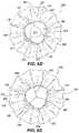
- FIG. 2Billustrates a top plan view of the exemplary frame of FIG. 2A , consistent with various embodiments of the present disclosure.
- FIG. 2Cillustrates an enlarged view of an atrial anchoring arm and a ventricular anchoring leg of the exemplary frame of FIG. 2A , consistent with various embodiments of the present disclosure.
- FIG. 2Dillustrates another front elevation view of the exemplary frame of FIG. 2A , consistent with various embodiments of the present disclosure.
- FIG. 2Eillustrates another top plan view of the exemplary frame of FIG. 2A , consistent with various embodiments of the present disclosure.
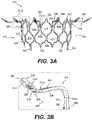
- FIG. 3Aillustrates a front elevation view of an inner frame of the exemplary frame of FIG. 2A , consistent with various embodiments of the present disclosure.
- FIG. 3Billustrates an enlarged view of an atrial anchoring arm of the exemplary inner frame of FIG. 3A , consistent with various embodiments of the present disclosure.
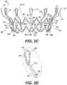
- FIG. 3Cillustrates a front elevation view of an outer frame of the exemplary frame of FIG. 2A , consistent with various embodiments of the present disclosure.
- FIG. 3Dillustrates an enlarged view of a ventricular anchoring leg of the exemplary outer frame of FIG. 3C , consistent with various embodiments of the present disclosure.
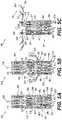
- FIG. 4Aillustrates a cross-sectional view of the exemplary frame of FIG. 2A , consistent with various embodiments of the present disclosure.
- FIG. 4Billustrates an enlarged view of a volume between an atrial anchoring arm and a ventricular anchoring leg of the exemplary frame of FIG. 4A , consistent with various embodiments of the present disclosure.
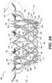
- FIGS. 5A-5Eillustrate structural changes in the exemplary frame of FIG. 2A during transitioning of the frame between a radially-contracted configuration and a radially-expanded configuration, consistent with various embodiments of the present disclosure.
- FIG. 6Aillustrates a front elevation view of an exemplary prosthetic valve, consistent with various embodiments of the present disclosure.
- FIG. 6Billustrates a cross-sectional view of the exemplary prosthetic valve of FIG. 6A without leaflets, consistent with various embodiments of the present disclosure.
- FIG. 6Cillustrates a cross-sectional view of the exemplary prosthetic valve of FIG. 6A with leaflets, consistent with various embodiments of the present disclosure.
- FIG. 6Dillustrates a top plan view of the exemplary prosthetic valve of FIG. 6A with uninflated leaflets, consistent with various embodiments of the present disclosure.
- FIG. 6Eillustrates a top plan view of the exemplary prosthetic valve of FIG. 6A with inflated leaflets, consistent with various embodiments of the present disclosure.
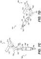
- FIG. 7Aillustrates an exemplary prosthetic valve delivery system, consistent with various embodiments of the present disclosure.
- FIG. 7Billustrates an enlarged view of a delivery capsule of the exemplary prosthetic valve delivery system of FIG. 7A , consistent with various embodiments of the present disclosure.
- FIG. 7Cillustrates an exemplary configuration of a telescoping catheter assembly and the delivery capsule of the exemplary prosthetic valve delivery system of FIG. 7A , consistent with various embodiments of the present disclosure.
- FIG. 7Dillustrates another exemplary configuration of the telescoping catheter assembly and delivery capsule of FIG. 7C , consistent with various embodiments of the present disclosure.
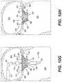
- FIG. 8Aillustrates another enlarged view of the exemplary delivery capsule of the prosthetic valve delivery system of FIG. 7A in a closed configuration, consistent with various embodiments of the present disclosure.
- FIG. 8Billustrates the exemplary delivery capsule of FIG. 8A in an open configuration, consistent with various embodiments of the present disclosure.
- FIG. 8Cillustrates an interior view of the exemplary delivery capsule of FIG. 8A in the closed configuration, consistent with various embodiments of the present disclosure.
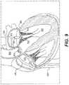
- FIG. 9illustrates advancement of the exemplary prosthetic valve delivery system of FIG. 7A into the left atrium, consistent with various embodiments of the present disclosure.
- FIGS. 10A-10Hdepict implantation of the prosthetic valve of FIGS. 6A-6E within a native mitral valve by the exemplary prosthetic valve delivery system of FIG. 7A , consistent with various embodiments of the present disclosure.
- an “atrial direction”may refer to a direction extending towards an atrium of the heart.
- an atrial directionmay refer to a direction extending towards the left atrium.
- an atrial directionmay refer to a direction extending away from an adjacent atrioventricular valve (e.g., the mitral valve) and further into the atrium.
- an atrial directionmay refer to a direction extending upwards from prosthetic valve 6000 towards atrium 9010 .
- an atrial directionneed not necessarily be parallel to a longitudinal axis of a prosthetic valve (e.g., longitudinal axis 2800 illustrated in FIG. 2A ), so long as the direction is angled towards an atrium.
- the atrial directionmay be parallel to a longitudinal axis of a prosthetic valve in some cases.
- a “non-ventricular direction”may refer to a direction that does not extend towards a ventricle of the heart.
- a “non-ventricular direction”may extend in an atrial direction, or it may extend laterally in a direction perpendicular to a ventricular direction.
- a “ventricular direction”may refer to a direction extending towards a ventricle of the heart. From a location within the left atrium or the mitral valve, a ventricular direction may refer to a direction extending towards the left ventricle. Additionally, from a location within a ventricle (e.g., the left ventricle), a ventricular direction may refer to a direction extending away from an adjacent atrioventricular valve (e.g., the mitral valve) and further into the ventricle. For example, in FIGS. 10G and 10H , a ventricular direction may refer to a direction extending downwards from prosthetic valve 6000 towards ventricle 9020 .
- a ventricular directionneed not necessarily be parallel to a longitudinal axis of a prosthetic valve (e.g., longitudinal axis 2800 illustrated in FIG. 2A ), so long as the direction is angled towards a ventricle.
- the ventricular directionmay be parallel to a longitudinal axis of a prosthetic valve in some cases.
- a “non-atrial direction”may refer to a direction that does not extend towards an atrium of the heart.
- a non-atrial directionmay extend in a ventricular direction, or it may extend laterally in a direction perpendicular to an atrial direction.
- Exemplary embodimentsgenerally relate to prosthetic valves for implantation within a native valve and methods for implanting prosthetic valves within a native valve.
- exemplary embodimentsgenerally relate to systems and methods for implantation of prosthetic valves by prosthetic valve delivery systems. While the present disclosure provides examples relating to prosthetic heart valves, and in particular prosthetic mitral valves, as well as delivery systems for prosthetic heart valves, it should be noted that aspects of the disclosure in their broadest sense are not limited to a prosthetic heart valve. Rather, the foregoing principles may be applied to other prosthetic valves as well.
- the term prosthetic valverefers generally to an implantable valve configured to restore and/or replace the functionality of a native valve, such as a diseased or otherwise impaired native heart valve.
- An exemplary prosthetic valvemay include a prosthetic valve configured to render a native valve structure non-functional, and may thus replace the function of the native valve.
- an exemplary prosthetic valvemay have a size and shape similar to the valve being replaced and may include a number of leaflet-like structures to regulate fluid flow and prevent backflow of blood through the valve.
- an exemplary prosthetic valvemay also include a prosthetic valve configured to leave the native valve structure intact and functional.
- An exemplary prosthetic valvemay include a mitral valve, tricuspid valve, aortic valve, or pulmonary valve, as well as a valve outside of the heart, such as a venous valve, lymph node valve, ileocecal valve, or any other structure configured to control and/or regulate fluid flow in the body.
- An exemplary prosthetic valvemay additionally or alternatively be configured to replace a failed bioprosthesis, such as a failed heart valve prosthesis.
- FIG. 1Aillustrates a front elevation view of an exemplary frame 1000 for a prosthetic valve.
- FIG. 1Billustrates a perspective view of frame 1000 .
- Frame 1000may be constructed of a shape memory material such as nickel titanium alloy (Nitinol) and may be configured to support other components of the prosthetic valve, such as prosthetic leaflets and protective cover layers.
- Frame 1000may include an annular outer frame 1200 and an inner frame 1400 situated at least partially within the outer frame 1200 .
- Annular outer frame 1200 and inner frame 1400may be secured together by pins, screws, welding, soldering, adhesive, magnets, and/or any other suitable mechanism.
- FIGS. 1A and 1Bdepict annular outer frame 1200 and inner frame 1400 connected by a plurality of connector pins 1040 .
- Annular outer frame 1200may include an outer frame tubular portion 1220 , which may be formed of a plurality of struts intersecting at junctions to form a wire mesh, stent-like, or cage-like structure of the outer frame tubular portion 1220 . Annular outer frame 1200 may also include at least one ventricular anchoring leg 1240 , which may be configured to extend radially outward from the outer frame tubular portion and which may contact, or otherwise engage, tissue within or near the native valve to anchor the prosthetic valve within the native valve. In some embodiments, exemplary valve frame 1000 may include twelve ventricular anchoring legs 1240 , which may be configured to engage ventricular tissue of a native atrioventricular valve.
- Inner frame 1400may include an inner frame tubular portion 1420 , which may be formed of a plurality of struts intersecting at junctions to form a wire mesh, stent-like, or cage-like structure of the inner frame tubular portion 1420 .
- Inner frame 1400may also include at least one atrial anchoring arm 1440 , which may be configured to extend radially outward from the inner frame tubular portion and which may contact, or otherwise engage, tissue within or near the native valve to anchor the prosthetic valve within the native valve.
- exemplary valve frame 1000may include twelve atrial anchoring arms 1440 , which may be configured to engage atrial tissue of a native atrioventricular valve.
- Outer frame tubular portion 1220 and inner frame tubular portion 1420may together form an annular valve body 1020 of the prosthetic valve, which may have at least one opening and from which the ventricular anchoring legs 1240 and atrial anchoring arms 1440 may extend.
- Annular valve body 1020may include an axial lumen 1022 extending through the annular valve body 1020 along a longitudinal axis 1800 of the prosthetic valve.
- annular valve body 1020may be configured to receive a flow control device, such as one or more prosthetic leaflets, within axial lumen 1022 .
- annular valve body 1020may include one or more atrial end delivery posts 1027 along an atrial end (i.e., top end) of the annular valve body and/or one or more ventricular end delivery posts 1028 along a ventricular end (i.e., bottom end) of the annular valve body.
- Delivery posts 1027 and 1028may be configured to removably engage a delivery device of the prosthetic valve, for example, to assist with placement of frame 1000 within or near a native valve.
- FIG. 2Aillustrates a front view of another exemplary frame 2000 for a prosthetic valve.
- FIG. 2Billustrates a top plan view of the frame 2000 .
- Frame 2000may include an annular outer frame 2200 and an inner frame 2400 situated at least partially within the annular outer frame 2200 .
- Annular outer frame 2200 and inner frame 2400may be secured together by pins, screws, welding, soldering, adhesive, magnets, and/or any other suitable mechanism.
- FIGS. 2A and 2Bdepict annular outer frame 2200 and inner frame 2400 connected by a plurality of connector pins 2040 .
- Annular outer frame 2200may include an outer frame tubular portion 3605 , which may be formed of a plurality of struts intersecting at junctions to form a wire mesh, stent-like, or cage-like structure of the outer frame tubular portion 3605 .
- annular outer frame 2200may include outer frame atrial circumferential struts 3608 a , outer frame leg base struts 3608 b , and outer frame ventricular circumferential struts 3608 c intersecting at atrial end outer frame junctions 3602 , leg attachment junctions 3802 , outer frame junctions 3804 , and ventricular end outer frame junctions 3604 to form outer frame tubular portion 3605 .
- Annular outer frame 2200may also include at least one ventricular anchoring leg 2240 , which may extend from leg attachment junction 3802 of the outer frame tubular portion 3605 and which may be configured to engage ventricular tissue of a native valve to anchor the prosthetic valve in the native valve.
- the at least one ventricular anchoring leg 2240may include a proximal leg end 3622 , which may be the end of the leg connected to the outer frame tubular portion, and a distal leg end 2244 , which may be situated radially outward from the outer frame tubular portion.
- the at least one ventricular anchoring leg 2240may include at least one opening 2242 .
- Inner frame 2400may include an inner frame tubular portion 3005 , which may be formed of a plurality of struts intersecting at junctions to form a wire mesh, stent-like, or cage-like structure of the inner frame tubular portion 3005 .
- inner frame 2400may include inner frame atrial struts 3008 a , inner frame intermediate struts 3008 b , and inner frame ventricular struts 3008 c intersecting at atrial end inner frame junctions 3002 , arm attachment junctions 3202 , inner frame strut junctions 3204 , and ventricular end inner frame junctions 3004 to form inner frame tubular portion 3005 .
- Inner frame 2400may also include at least one atrial anchoring arm 2440 , which may extend from arm attachment junction 3202 of the inner frame tubular portion 3005 and which may be configured to engage atrial tissue of a native valve to anchor the prosthetic valve in the native valve.
- the at least one atrial anchoring arm 2440may include a proximal arm end 3020 , which may be the end of the arm connected to the inner frame tubular portion, and a distal arm end 2444 , which may be situated radially outward from the inner frame tubular portion.
- the at least one atrial anchoring arm 2440may include a proximal arm opening 2441 and a distal arm opening 2442 .
- Outer frame tubular portion 3605 and inner frame tubular portion 3005may together form an annular valve body 2020 of the prosthetic valve, which may have at least one opening and from which the ventricular anchoring legs 2240 and atrial anchoring arms 2440 may extend.
- Annular valve body 2020may include an axial lumen 2022 extending through the annular valve body 2020 along a longitudinal axis 2800 of the prosthetic valve.
- Annular valve body 2020may have an atrial end 2024 , a ventricular end 2025 opposite the atrial end, and an intermediate portion 2026 extending between the atrial and ventricular ends.
- the atrial endmay refer to the portion of the annular valve body configured to be situated at a location within the atrium that is furthest from an adjacent ventricle, when the prosthetic valve is implanted in a native valve.
- the ventricular endmay refer to the portion of the annular valve body configured to be situated at a location within the ventricle that is furthest from an adjacent atrim, when the prosthetic valve is implanted in a native valve.
- the intermediate portion 2026may extend between the atrial end 2024 and ventricular end 2025 .
- annular valve body 2020may include one or more ventricular end delivery posts 1028 along the ventricular end 2025 of the annular valve body.
- Axial lumen 2022may include an inlet opening 2032 at the atrial end of the annular valve body, as well as an outlet opening 2036 at the ventricular end of the annular valve body.
- FIG. 2Cillustrates an enlarged view of an atrial anchoring arm 2440 and a ventricular anchoring leg 2240 of frame 2000 .
- Ventricular anchoring leg 2240may include an inner, atrially-facing leg surface 2248 and an outer, ventricularly-facing leg surface 2249 .
- Atrial anchoring arm 2440may include an atrially-facing arm surface 2448 and a ventricularly-facing arm surface 2449 .
- atrial anchoring arm 2440may include an arm portion 2446 configured to be arranged in a common lateral plane with leg portion 2246 of the ventricular anchoring leg 2240 . That is, leg portion 2246 and arm portion 2446 may be positioned at the same axial position along longitudinal axis 2800 .
- FIG. 2Dillustrates another front elevation view of frame 2000 .
- the exemplary prosthetic valve, as well as frame 2000may have an axial height 2560 , which may extend between terminal arm ends 2444 and ventricular end 2025 of the annular valve body.
- Inner frame tubular portion 3005may have an axial height 2530 , which may extend between atrial end inner frame junctions 3002 and ventricular end inner frame junctions 3004 .
- Annular outer frame 2200may have an axial height 2550 , which may extend between terminal leg ends 2244 and ventricular end 2025 of the annular valve body.
- Outer frame tubular portion 3605may have an axial height 2570 , which may extend between atrial end outer frame junctions 3602 and ventricular end outer frame junctions 3604 .
- frame 2000may have a ventricular device protrusion distance 2540 , which may represent the distance over which the prosthetic valve protrudes into a left ventricle when the prosthetic valve is implanted in a native mitral valve.
- Annular valve body 2020may include a valve inlet radius 2520 , which may be the radius of atrial inlet opening 2032 .
- FIG. 2Eillustrates another top plan view of frame 2000 .
- the atrial anchoring arms 2440may have a length 2580
- the ventricular anchoring legs 2240may have a length 2590 .
- the terminal arm ends 2444may define an atrial anchoring arm circumference 2640 .
- the terminal leg ends 2244may define a ventricular anchoring leg circumference 2620 , which may be concentric with atrial anchoring arm circumference 2640 .
- Inflexible portions 3402 of the atrial anchoring arms(illustrated in FIG. 3B ) may have a length 2581 .
- Serpentine structures 3406 of the atrial anchoring arms(illustrated in FIG. 3B ) may have a length 2582 .
- FIG. 3Aillustrates a front elevation view of inner frame 2400 .
- the atrial end inner frame junctions 3002 and ventricular end inner frame junctions 3004may form the atrial end and ventricular end, respectively, of inner frame 2400 .
- Inner frame intermediate portion 3006may extend between atrial end inner frame junctions 3002 and ventricular end inner frame junctions 3004 .
- Inner frame tubular portion 3005may have a radially inner surface 3018 and a radially outer surface 3016 .
- Inner frame atrial struts 3008 a and inner frame intermediate struts 3008 bmay intersect at atrial end inner frame junctions 3002 , arm attachment junctions 3202 , and strut junctions 3204 to form a first, atrial row of closed cells 3012 .
- Inner frame intermediate struts 3008 b and inner frame ventricular struts 3008 cmay intersect at arm attachment junctions 3202 , strut junctions 3204 , and ventricular end inner frame junctions 3004 to form a second, ventricular row of closed cells 3014 .
- At least one inner frame atrial strut 3008 amay have a cross-sectional area 3010 .
- At least one atrial anchoring arm 2440may have a cross-sectional area 3022 .
- FIG. 3Billustrates an enlarged view of an atrial anchoring arm 2440 of inner frame 2400 .
- Atrial anchoring arm 2440may include a proximal arm portion 3502 configured to extend in an atrial direction, intermediate arm portion 3504 configured to extend in a ventricular direction, and distal arm portion 3506 configured to extend in an atrial direction.
- Arm transition portion 3508may represent the transition between intermediate arm portion 3504 and distal arm portion 3506 .
- Atrial anchoring arm 2440may also include an inflexible portion 3402 extending to proximal arm end 3020 , as well as a serpentine structure 3406 , which may be situated radially external to the inflexible portion 3402 .
- Inflexible portion 3402may have a proximal end 3402 p , a distal end 3402 d , and a cross-sectional area 3402 c .
- Serpentine structure 3406may have a cross-sectional area 3406 c .
- atrial anchoring arm 2440may include a terminal arm region 3408 situated radially external to serpentine structure 3406 .
- Distal arm opening 2442may be situated within terminal arm region 3408 .
- FIG. 3Cillustrates a front elevation view of outer frame 2200 .
- the atrial end outer frame junctions 3602 and ventricular end outer frame junctions 3604may form the atrial end and ventricular end, respectively, of annular outer frame 2200 .
- Outer frame intermediate portion 3606may extend between atrial end outer frame junctions 3602 and ventricular end outer frame junctions 3604 .
- Outer frame tubular portion 3605may have a radially outer surface 3618 and a radially inner surface 3620 .
- outer frame atrial circumferential struts 3608 a , outer frame leg base struts 3608 b , and outer frame ventricular circumferential struts 3608 cmay intersect at the atrial end outer frame junctions 3602 , leg attachment junctions 3802 , outer frame junctions 3804 , and ventricular end outer frame junctions 3604 to form closed cells 3616 .
- At least one outer frame atrial circumferential strut 3608 amay have a cross-sectional area 3610 and a width 3612 .
- At least one outer frame leg base strut 3608 bmay have a cross-sectional area 3614 .
- At least one ventricular anchoring legmay have a cross-sectional area 3624 and a radially outer surface width 3626 .
- FIG. 3Dillustrates an enlarged view of a portion of a ventricular anchoring leg 2240 of annular outer frame 2200 .
- Ventricular anchoring leg 2240may include a first, proximal curved portion 3807 and a second, distal curved portion 3808 .
- proximal curved portion 3807may face radially outward.
- distal curved portion 3808may face radially inwards.
- FIG. 4Aillustrates a cross-sectional view of frame 2000
- FIG. 4Billustrates an enlarged view of a portion of FIG. 4A depicting a volume 4000 formed between the atrial anchoring arms 2440 and ventricular anchoring legs 2240
- FIG. 4Balso depicts an outer surface 4010 and inner surface 4020 of annular valve body 2020
- volume 4000may be bounded by the ventricularly-facing surfaces 2449 of atrial anchoring arms 2440 , by the inner, atrially-facing surfaces 2248 of ventricular anchoring legs 2240 , and by the outer surface 4010 of the annular valve body 2020 .
- FIG. 5Aillustrates a configuration of the exemplary prosthetic valve in which annular valve body 2020 , atrial anchoring arms 2440 , and ventricular anchoring legs 2240 are arranged in a radially-contracted configuration.
- the configuration illustrated in FIG. 5Amay constitute a radially-contracted configuration of the prosthetic valve.
- FIG. 5Billustrates a configuration of the exemplary prosthetic valve in which annular valve body 2020 and atrial anchoring arms 2440 are arranged in a radially-contracted configuration.
- the ventricular anchoring legs 2240may deflect radially outward away from annular valve body 2020 , into a radially-expanded configuration of the ventricular anchoring legs 2240 .
- FIG. 5Cillustrates a configuration of the exemplary prosthetic valve in which annular valve body 2020 and ventricular anchoring legs 2240 are arranged in a radially-contracted configuration.
- the atrial anchoring arms 2440may deflect radially outward away from annular valve body 2020 , into a radially-expanded configuration of the atrial anchoring arms 2440 .
- FIG. 5Dillustrates a configuration of the exemplary prosthetic valve in which the atrial anchoring arms 2440 and ventricular anchoring legs 2240 may deflect radially outward away from annular valve body 2020 into their respective radially-expanded configurations, while annular valve body 2020 remains in a radially-contracted configuration.
- an axial distance 5004may be formed between the atrial anchoring arms 2440 and the terminal ends 2244 of the ventricular anchoring legs 2240 .
- FIG. 5Eillustrates a configuration of the exemplary prosthetic valve in which annular valve body 2020 , atrial anchoring arms 2440 , and ventricular anchoring legs 2240 are arranged in a radially-expanded configuration.
- the configuration illustrated in FIG. 5Emay constitute a radially-expanded configuration of the prosthetic valve.
- FIG. 6Aillustrates a front elevation view of prosthetic valve 6000 .
- prosthetic valve 6000may be assembled upon frame 2000 .
- Prosthetic valve 6000may be configured for implantation within or near a native valve structure and may be configured to restore and/or replace the functionality of a native valve, such as a diseased or otherwise impaired native valve.
- Prosthetic valve 6000may include valve frame 2000 , including annular valve body 2020 , the atrial anchoring arms 2440 , and the ventricular anchoring legs 2240 .
- Prosthetic valve 6000may also include a skirt layer 6100 configured around an external surface of a portion of the annular valve body.
- Prosthetic valve 6000may additionally include a first cuff sheet 6210 , which may be connected to skirt layer 6100 via stitching 6104 , as well as a second cuff sheet 6220 , which may be connected to first cuff sheet 6210 via stitching 6420 .
- the first cuff sheet 6210 and second cuff sheet 6220by extend around the terminal ends 2444 of the atrial anchoring arms 2440 .
- Skirt layer 6100 , first cuff sheet 6210 , and second cuff sheet 6220may be constructed of fluid-impermeable material and may accordingly be configured to prevent passage of blood or other fluids through portions of the prosthetic valve 6000 outside of the axial lumen 2022 .
- prosthetic valve 6000may additionally include a protective sleeve 6102 wrapped around the rim 6800 of the ventricular outlet opening of annular valve body 2020 ; protective sleeve 6102 may be secured to annular valve body 2020 by stitching 6108 .
- prosthetic valve 6000may include at least one liner 6310 extending around an external surface of the ventricular anchoring legs 2240 , with at least one protective layer 6330 positioned around the distal leg ends 2244 and at least one protective covering 6320 wrapped around the proximal leg ends 3622 .
- the at least one protective covering 6320may be secured to the skirt layer 6100 via stitching 6322 .
- FIG. 6Billustrates a cross-sectional view of prosthetic valve 6000 , without prosthetic leaflets situated within the axial lumen 2022 .
- prosthetic valve 6000may additionally include a liner 6400 covering at least a portion of the inner surface 4020 of the annular valve body 2020 .
- Liner 6400may be secured to the annular valve body 2020 via stitching 6430 and to the second cuff sheet 6220 via stitching 6410 .
- First cuff sheet 6210 , second cuff sheet 6220 , and inner liner 6400may together form an inflatable cuff 6200 having an interior volume 6500 .
- inflatable cuff 6200may be secured to atrial anchoring arm 2440 via connector 6440 .
- Bloodmay enter the cuff 6200 through openings 6230 , causing the cuff 6200 to inflate radially outwards and axially in an atrial direction.
- cuff 6200may inflate radially outwards and press against tissue of the native valve. This engagement between the cuff and tissue of the native valve may form a barrier to flow of blood and other fluids around the outer circumference of the prosthetic valve 6000 .
- FIG. 6Cillustrates a cross-sectional view of prosthetic valve 6000 with prosthetic leaflets 6602 and 6604 situated within the axial lumen 2022 .
- prosthetic valve 6000may also include a third prosthetic leaflet 6606 , which may not be visible in the view of FIG. 6C .
- the leaflets 6602 , 6604 , and 6606may be secured to inner liner 6400 via stitching 6608 and may include a connector 6610 wrapping around the ventricular end delivery posts 2028 to secure the leaflets 6602 , 6604 , and 6606 to the valve frame 2000 .
- FIG. 6Dillustrates a top plan view of prosthetic valve 6000 , with leaflets 6602 , 6604 , and 6606 arranged in an open, uninflated configuration. In the open configuration, a space may be formed in the middle of the leaflets, permitting fluid to pass through the axial lumen 2022 of the prosthetic valve 6000 .
- FIG. 6Eillustrates a top plan view of prosthetic valve 6000 , with leaflets 6602 , 6604 , and 6606 arranged in a closed, coapted configuration. In the closed configuration, the leaflets may press together such that the opening between them is closed. For example, the point of contact 6007 between two adjacent leaflets may extend to the center of the axial lumen; as a result, the leaflets may block fluid passage through the axial lumen 2022 of the prosthetic valve 6000 .
- FIG. 7Aillustrates a prosthetic valve delivery system 7000 .
- Delivery system 7000may be configured to deliver an implant prosthetic valve 6000 within a native valve, such as a native mitral valve.
- Prosthetic valve delivery system 7000may include a control handle assembly 7100 , a telescoping catheter assembly 7200 , a delivery capsule 7300 configured to retain a prosthetic valve (e.g. valve 6000 ), and, optionally, a stand 7400 .
- a prosthetic valvee.g. valve 6000
- Control handle assembly 7100may include an outer sheath control handle 7120 having a steering knob 7122 configured to steer an outer sheath 7210 of the telescoping catheter assembly 7200 .
- Control handle assembly 7100may also include a guide catheter control handle 7140 having a steering knob 7142 configured to steer a guide catheter 7220 of the telescoping catheter assembly 7200 .
- Control handle assembly 7100may also include an implant catheter control handle 7160 having a steering knob 7168 configured to steer an implant catheter 8100 of the telescoping catheter assembly 7200 .
- Implant catheter control handle 7160may also include a proximal capsule portion slider 7162 , a distal capsule portion knob 7170 , and a distal capsule portion knob lock 7172 configured to control release of the prosthetic valve 6000 from within delivery capsule 7300 .
- Implant catheter control handle 7160may also include a slide lock 7166 configured to lock the implant catheter control handle 7160 at a position within track 7420 of stand 7400 .
- Control handle assembly 7100may also include a cradle 7180 , which may be secured to stand 7400 via a locking mechanism that can be released by actuated of release button 7184 .
- Cradle 7180may include a rotation knob 7182 configured to control rotation of the outer sheath 7210 and guide catheter 7220 .
- Cradle 7180may also include a rotation knob 7186 configured to control rotation of the implant catheter 8100 .
- Cradle 7180may also include a knob 7188 configured to control relative axial movement between outer sheath control handle 7120 (which may be secured to outer sheath 7210 ) and guide catheter control handle 7140 (which may be secured to guide catheter 7220 ).
- FIG. 7Billustrates an enlarged view of delivery capsule 7300 of prosthetic valve delivery system 7000 .
- Delivery capsule 7300may include a proximal capsule portion 7320 and a distal capsule portion 7340 with a nose cone 7360 secured to the distal capsule portion 7340 .
- a nose cone distal tip 7365may form the distal end of the delivery capsule 7300 .
- the telescoping catheter assembly 7200may include a capsule shaft 7230 secured to, and configured to control movement of, the proximal capsule portion 7320 (e.g., due to connection 8400 between the capsule shaft 7230 and proximal capsule portion 7320 , as illustrated in FIG. 8C ).
- Implant catheter 8100may extend within proximal capsule portion 7320 and may have a valve anchor disc 8200 connected to the distal end of the implant catheter 8100 .
- a torque shaft 8300may extend from the implant catheter 8100 and may be connected to distal capsule portion 7340 ; accordingly, torque shaft 8300 may be configured to control axial movement of the distal capsule portion 7340 relative to the implant catheter 8100 and valve anchor disc 8200 .
- the proximal capsule portion 7320 and a distal capsule portion 7340may be configured to retain prosthetic valve 6000 , with the prosthetic valve 6000 secured against axial movement by valve anchor disc 8200 .
- Control handle assembly 7100may be configured to control movement of the proximal capsule portion 7320 and a distal capsule portion 7340 , and thus may also control release of the prosthetic valve 6000 from within the delivery capsule 7300 .
- FIGS. 7C and 7Dillustrate exemplary configurations of the telescoping catheter assembly 7200 .
- Outer sheath 7210 and guide catheter 7220may include respective bending portions 7215 and 7225 , at which the outer sheath 7210 and guide catheter 7220 may be configured to bend within their respective steering planes 7212 and 7222 .
- bending of the outer sheath 7210 within the first steering plane 7212may be controlled by the outer sheath steering knob 7122 of the control handle assembly 7100 .
- bending of the guide catheter 7220 within the second steering plane 7222may be controlled by the guide catheter steering knob 7142 of the control handle assembly 7100 .
- the outer sheath 7210 , guide catheter 7220 , and implant catheter 8100may be steered so as to correctly position the delivery capsule 7300 within a native valve for implantation of the prosthetic valve.
- FIG. 8Aillustrates an enlarged view of delivery capsule 7300 in a closed configuration
- FIG. 8Billustrates an enlarged view of delivery capsule 7300 in an open configuration
- the distal capsule portion 7340 and proximal capsule portion 7320may be brought together to form an enclosed compartment in which prosthetic valve 6000 may be retained.
- the distal capsule portion 7340 and proximal capsule portion 7320may be drawn apart.
- the delivery capsule 7300may be configured such that the distal capsule portion 7340 and proximal capsule portion 7320 are moved apart from each other, the prosthetic valve 6000 may be sequentially deployed from within the delivery capsule and implanted within a native valve.
- FIG. 8Cillustrates an interior view of delivery capsule 7300 with prosthetic valve 6000 retained within the delivery capsule. Although only the valve frame 2000 of the prosthetic valve 6000 is illustrated in FIG. 8C , one of ordinary skill will understand that the entire prosthetic valve 6000 depicted in FIGS. 6A-6E may be retained within delivery capsule 7300 in the configuration illustrated in FIG. 8C .
- valve anchor disc 8200may include a number of recesses 8205 configured to receive and retain the ventricular end delivery posts 2028 of the prosthetic valve 6000 .
- the valve anchor disc 8200may include at least the same number of recesses 8205 as there are delivery posts 2028 of the prosthetic valve 6000 .
- the delivery posts 2028may be retained within the recesses 8205 so long as the annular valve body 2020 remains in a radially-contracted configuration; the engagement between the valve anchor disc 8200 and delivery posts 2028 may secure the prosthetic valve 6000 against axial movement. Upon radial expansion of the annular valve body 2020 , the delivery posts 2028 may slide or expand out of the recesses 8205 , freeing the prosthetic valve 6000 from engagement with the valve anchor disc 8200 .
- FIG. 9illustrates one exemplary advancement route of the delivery capsule 7300 to the left atrium.
- the delivery capsule 7300may be steered through the vena cava into the right atrium 9210 and may pierce the interatrial septum and enter the left atrium 9010 .
- the delivery capsulemay be delivered to the heart by other routes.
- FIG. 9also depicts the left ventricle 9020 , the mitral valve 9030 , the chordae tendineae 9022 , the aortic valve 9045 , and the aorta 9040 .
- FIGS. 10A-10Hdepict an exemplary implantation method of prosthetic valve 6000 within a mitral valve 9030 .
- the delivery capsule 7300may be coaxially aligned with the mitral valve 9030 .
- the prosthetic valve 6000may be held within the delivery capsule 7300 while the prosthetic valve is arranged in the configuration of FIG. 5A .
- the delivery capsule 7300may be distally advanced into the mitral valve 9030 .
- the distal capsule portion 7340may be distally advanced relative to the rest of the delivery capsule 7300 .
- the ventricular anchoring legs 2240may be released from the delivery capsule 7300 within the atrium 9010 .
- the prosthetic valve 6000may assume the configuration of FIG. 5B when the ventricular anchoring legs 2240 are released in the step depicted in FIG. 10C .
- the released ventricular anchoring legs 2240may be passed through the mitral valve 9030 and into the left ventricle 9020 .
- the released legs 2240may be proximally retracted until the ventricular anchoring legs come into contact with the ventricular tissue of the mitral valve 9030 .
- the proximal capsule portion 7320may be retracted proximally, thus releasing the atrial anchoring arms 2440 within atrium 9010 while the annular valve body 2020 remains radially constrained within the distal capsule portion 7340 .
- the prosthetic valve 6000may assume the configuration of FIG. 5D when the atrial anchoring arms 2440 are released in the step of FIG. 10F .
- the distal capsule portion 7340may be advanced further until the annular valve body 2020 is released from the capsule and allowed to radially expand. Radial expansion of the annular valve body 2020 may allow the prosthetic valve to assume the fully-expanded configuration illustrated in FIG. 5E . At this stage, prosthetic valve 6000 may be securely implanted within mitral valve 9030 . In FIG. 10H , the delivery system 7000 , including capsule 7300 , may be removed.
- Prosthetic heart valve 6000illustrated in FIGS. 6A-6E , is one example of a prosthetic valve according to the present disclosure.
- an exemplary prosthetic valvemay be configured for implantation within a native atrioventricular valve and may regulate blood flow between the atrium and ventricle.
- prosthetic heart valve 6000 illustrated in FIGS. 6A-6Cmay include a fluid-impervious cuff 6200 configured to extend from an inner lumen 2022 of the prosthetic valve to terminal arm ends 2444 of a plurality of atrial anchoring arms 2440 . Because cuff 6200 is constructed of a fluid-impervious material, cuff 6200 may be configured to minimize or block flow of blood and other fluids through any portion of the prosthetic valve 6000 except for lumen 2022 .
- Atrial anchoring arms 2440 of the prosthetic valvemay be configured to contact and, in some embodiments, press against atrial tissue of a native heart valve. This is illustrated in FIGS. 10G-10H , which depict atrial anchoring arms 2440 of prosthetic valve 6000 arranged in contact with, and exerting a ventricularly-directed force (that is, a force directed downwards toward ventricle 9020 ) upon atrial tissue of native mitral valve 9030 .
- cuff 6200 of prosthetic valve 6000may also be configured to minimize or block passage of blood and other fluids between the prosthetic valve 6000 (including terminal arm ends 2444 ) and native valve tissue, a condition known as perivalvular leakage.
- prosthetic valve 6000may be configured to prohibit passage of blood and other fluids between atrium 9010 and ventricle 9020 , except by passage through inner lumen 2022 , in which leaflets 6602 , 6604 , and 6606 may be situated.
- an exemplary prosthetic valvemay be expandable, such as between a radially-contracted configuration (for example, a crimped state) and a radially-expanded configuration.
- the exemplary prosthetic valvemay be configured to be radially contracted into the radially-contracted configuration for introduction to the implantation site, such as on or within a delivery device.
- the radially-contracted configurationmay also be a delivery configuration, in which the prosthetic valve is arranged for delivery to the implantation site.
- the prosthetic valveOnce at or near the implantation site, the prosthetic valve may be fully radially-expanded, which may anchor the prosthetic valve at the implantation site.
- the radially-expanded configurationmay also be a deployed configuration, in which the prosthetic valve is released from the delivery tool and seated at the implantation site.
- an exemplary prosthetic valvemay be configured for self-expansion to the radially-expanded configuration; that is, the prosthetic valve may be biased to assume the radially-expanded configuration due to, at least in part, the design and/or material composition of the prosthetic valve.
- the self-expanding prosthetic valvemay be constructed of a shape memory material such as nickel titanium alloy (Nitinol), which may permit the prosthetic valve to expand to a pre-determined diameter upon removal of a constraining force and/or application of heat or energy.
- the prosthetic valvemay be contracted and held in the radially-contracted configuration by a constraining device, such as a sheath, catheter, stent, or delivery capsule.
- FIGS. 8A-80illustrates prosthetic heart valve 6000 held in a radially-contracted configuration within delivery capsule 7300 .
- the constraining forcemay be removed and the prosthetic valve allowed to self-expand to the radially-expanded configuration.
- an exemplary prosthetic valvemay be configured to expand due to application of radially expansive forces thereupon.
- the prosthetic valvemay be placed, in its radially-contracted configuration, upon an expansion device such as a balloon catheter.
- the expansion devicemay exert an outwardly-directed force upon the prosthetic valve, causing it to expand to the fully-expanded configuration.
- a prosthetic valvemay be configured for implantation at a treatment site within the body, such as within or adjacent to a native valve structure, such as a native mitral valve.
- a prosthetic valvemay be configured for transcatheter delivery to the implantation site via a variety of approaches, such as transapically, transatrially, and/or transseptally.
- the prosthetic valvemay be configured for implantation in the annulus or orifice of a native valve structure (e.g., a native mitral valve).
- a native mitral valvee.g., a native mitral valve
- an exemplary prosthetic valvemay be configured to grasp tissue of the native valve to firmly anchor the prosthetic valve within the native valve.
- an exemplary prosthetic valvemay be configured to grasp the native leaflets and/or native valve annulus to firmly seat the prosthetic valve within the valve annulus, thus preventing the prosthetic valve from migrating or dislodging from within the native valve annulus.
- the prosthetic valvemay include a valve body.
- the exemplary valve bodymay be configured to receive or otherwise support a flow control device, such as one or more leaflets, for regulating flow of blood or other bodily fluids through the prosthetic valve.
- the flow control devicee.g., leaflets
- the flow control devicemay be secured directly to the valve body and/or to an additional structure that is in turn secured to the valve body.
- the exemplary valve bodymay be annular or ring-shaped and may thus have at least one opening therein.
- valve body 2020may include axial lumen 2022 extending longitudinally through valve body 2020 .
- the valve bodymay be sized and configured to be seated within the orifice of a native heart valve (e.g., a native mitral valve).
- a native mitral valvee.g., a native mitral valve
- valve body 2020may be situated within the orifice of mitral valve 9030 , specifically between native leaflets 9032 .
- the valve bodymay be configured to have a smaller diameter, when fully-expanded, than the diameter of the orifice of the native heart valve.
- the valve bodymay be anchored in the native heart valve by anchoring structures, such as atrial anchoring arms and/or ventricular anchoring legs.
- anchoring structuressuch as atrial anchoring arms and/or ventricular anchoring legs.
- the valve bodymay be configured to expand to an equal or greater diameter than the diameter of the native heart valve orifice such that the valve body is anchored within the native heart valve.
- the valve bodymay have a circular, oval-shaped, elliptical, or D-shaped cross-section and may be symmetrical about at least one axis thereof.
- the valve bodymay have any suitable cross-sectional shape with at least one opening therein.
- at least a portion of the valve bodymay be cylindrical, with a substantially constant diameter along the entire length thereof.
- the valve bodymay have a variable diameter at different portions thereof (e.g., at different longitudinal portions thereof).
- such a configurationmay improve the seating of the valve body within the native heart valve orifice, providing an improved pressure fit therebetween.
- the exemplary valve bodymay be expandable, such as between a radially-contracted configuration and a radially-expanded configuration.
- an exemplary valve bodymay be configured to be radially contracted into the radially-contracted configuration for introduction to the implantation site, such as on or within a delivery device.
- the radially-contracted configurationmay also be a delivery configuration, in which the valve body is arranged for delivery to the implantation site.
- the valve bodyOnce at or near the implantation site, the valve body may be radially expanded, which may anchor the valve body at the implantation site.
- the radially-expanded configurationmay also be a deployed configuration, in which the valve body is released from the delivery tool and seated at the implantation site.
- an exemplary valve bodymay be configured for self-expansion to the radially-expanded configuration; that is, the valve body may be biased to assume the radially-expanded configuration due to, at least in part, the design and/or material composition of the valve body.
- the self-expanding valve bodymay be constructed of a shape memory material such as nickel titanium alloy (Nitinol), which may permit the valve body to expand to a pre-determined diameter upon removal of a constraining force and/or application of heat or energy.
- the valve bodymay be contracted and held in the radially-contracted configuration by a constraining device, such as a sheath, catheter, stent, or delivery capsule.
- FIGS. 8A-8Cillustrate an exemplary prosthetic heart valve held in a radially-contracted configuration within delivery capsule 7300 .
- the constraining forcee.g., as applied by delivery capsule 7300
- the valve bodymay be removed and the valve body allowed to self-expand to the radially-expanded configuration.
- exemplary valve bodiesmay be configured to expand due to application of radially expansive forces thereupon.
- the valve bodymay be placed, in its radially-contracted configuration, upon an expansion device such as a balloon catheter.
- the expansion devicemay exert an outwardly-directed force upon the valve body, causing it to expand to the fully-expanded configuration.
- the exemplary valve bodymay be configured to radially expand independently of other components of the expandable prosthetic valve.
- the exemplary valve bodymay be configured to remain in a radially-contracted configuration while other components of the expandable prosthetic valve, such as an anchoring feature, are deployed radially outward.
- FIGS. 5B-5Ddepict exemplary heart valve frame 2000 having valve body 2020 configured to remain in a radially-contracted configuration while atrial anchoring arms 2440 and ventricular anchoring legs 2240 are deployed radially outward (e.g., due to removal of a constraining delivery device from the arms and legs).
- the exemplary valve bodymay include an atrial end.
- the term atrial endmay refer to a portion of a feature of the valve body configured to be situated closest to an atrium of the heart when the feature is positioned outside of the atrium.
- the term atrial endmay refer to a portion of a feature of the valve body configured to be situated at a location within the atrium that is furthest from an adjacent ventricle.
- atrial end inner frame junctions 3002may constitute the atrial end 2024 of valve body 2020 because they are the portions of valve body 2020 that are situated within atrium 9010 at a location furthest from ventricle 9020 (as shown in FIG.
- the exemplary valve bodymay include a ventricular end.
- the term ventricular endmay refer to a portion of a feature of the valve body configured to be situated closest to a ventricle of the heart when the feature is positioned outside of the ventricle. Additionally, or alternatively, the term ventricular end may refer to a portion of a feature of the valve body configured to be situated at a location within the ventricle that is furthest from an adjacent atrium.
- ventricular end inner frame junction 3004 and ventricular end outer frame junction 3604may constitute the ventricular end 2025 of valve body 2020 .
- ventricular end inner frame junction 3004may constitute the ventricular end 2025 of valve body 2020 .
- ventricular end outer frame junction 3604may constitute the ventricular end 2025 of valve body 2020 .
- the exemplary valve bodymay include both an atrial end and a ventricular end opposite the atrial end. That is, the ventricular end of the valve body may be situated at a portion of the valve body that is furthest from and opposite of the atrial end of the valve body, with respect to a longitudinal axis of the valve body.
- the exemplary valve bodymay include an intermediate portion extending between the atrial end and ventricular end of the valve body. In some embodiments, the intermediate portion of the valve body may constitute every portion of the valve body situated in between the atrial end and ventricular end of the valve body. For example, as depicted in FIG. 2A , intermediate portion 2026 of valve body 2020 may include every portion of the valve body positioned between atrial end 2024 and ventricular end 2025 .
- the exemplary valve bodymay include a plurality of supporting members or struts.
- the strutsmay intersect at junctions to form a wire mesh, stent-like, or cage-like structure of the valve body.
- the struts of the valve bodymay be made of metals or alloys such as Nitinol.
- the struts of the valve bodymay be straight or curved.
- the struts of the valve bodymay be straight at certain portions of the struts and curved at other portions of the struts.
- the strutsmay be longitudinal or undulating.
- the plurality of strutsmay refer to two, three, four, five, six, seven, eight, nine, or ten struts. In other embodiments, the plurality of struts may refer to at least ten, at least twenty, at least thirty, at least forty, or at least fifty struts.
- FIG. 3Adepicts inner frame atrial struts 3008 a , inner frame intermediate struts 3008 b , and inner frame ventricular struts 3008 c within valve body 2020 , and FIG.
- 3Cdepicts outer frame atrial circumferential struts 3608 a , outer frame leg base struts 3608 b , and outer frame ventricular circumferential struts 3608 c within valve body 2020 .
- the struts of the valve bodymay meet or intersect at junctions of the valve body.
- a junctionmay be formed at a location at which at least two struts terminate that is, one or more exemplary struts may extend to and terminate at a junction at which the one or more exemplary struts intersects with one or more other struts.
- the strutsmay intersect at junctions to form a lattice or overlapping pattern.
- the strutsmay intersect at junctions to form cells, which may have any suitable cell shape.
- the struts of the valve bodymay intersect at junctions to form closed cells (i.e., cells completely enclosed by struts).
- the closed cellsmay be diamond-shaped, chevron-shaped, rectangular, triangular, circular, or may have any other suitable shape.
- FIG. 3Adepicts cells 3012 and 3014 in inner frame 2400 of valve body 2020
- FIG. 3Cdepicts cells 3616 in outer frame 2200 of valve body 2020 .
- two struts, three struts, four struts, five struts, or any other suitable number of strutsmay intersect at junctions of the valve body.
- the struts of the valve bodymay be arranged so as to form one or more frames of the exemplary prosthetic valve.
- the prosthetic valvemay include one or a plurality of tissue anchoring legs configured to anchor the prosthetic valve at the implantation site, such as within or near a native heart valve.
- the tissue anchoring legsmay be configured to engage ventricular tissue of a native mitral valve to anchor the prosthetic valve.
- the tissue anchoring legsmay be configured to be positioned at least partially within a ventricle upon implantation of the prosthetic valve, and to engage ventricular tissue of the native mitral valve.
- FIGS. 10E-10Hdepict tissue anchoring legs 2240 of an exemplary prosthetic heart valve situated within ventricle 9020 and engaging the ventricular side of native mitral valve 9030 .
- the tissue anchoring legsmay be configured to minimize or prevent migration of the prosthetic valve, including in an atrial direction (that is, towards the atrium). This may be due, at least in part, to the engagement of the tissue anchoring legs with the ventricular side of the native mitral valve and the inability of the tissue anchoring legs to pass through the valve annulus when the legs are expanded.
- the tissue anchoring legsmay be configured to grasp or clamp tissue of the native mitral valve to further anchor the prosthetic valve in place.
- one or more tissue anchoring legsmay include an anchoring feature to couple the legs to surrounding tissue.
- the prosthetic valvemay include two tissue anchoring legs, three tissue anchoring legs, four tissue anchoring legs, five tissue anchoring legs, six tissue anchoring legs, seven tissue anchoring legs, eight tissue anchoring legs, nine tissue anchoring legs, ten tissue anchoring legs, eleven tissue anchoring legs, twelve tissue anchoring legs, thirteen tissue anchoring legs, fourteen tissue anchoring legs, fifteen tissue anchoring legs, sixteen tissue anchoring legs, seventeen tissue anchoring legs, eighteen tissue anchoring legs, nineteen tissue anchoring legs, twenty tissue anchoring legs, or any other suitable number of tissue anchoring legs.
- exemplary prosthetic valve 6000may include twelve tissue anchoring legs 2240 .
- the tissue anchoring legsmay be configured to extend from an intermediate portion of the exemplary valve body. That is, the tissue anchoring legs may be configured to extend from a portion of the valve body other than the valve body atrial end and the valve body ventricular end.
- tissue anchoring legs 2240in FIG. 2A , extend from intermediate portion 2026 of valve body 2020 .
- the tissue anchoring legsmay be configured to extend from junctions situated within the intermediate portion of the valve body.
- the tissue anchoring legsmay be physically connected to the junctions within the intermediate portion of the valve body, such as by welding or adhesive.
- the tissue anchoring legsmay be integrally formed with the junctions within the intermediate portion of the valve body.
- the tissue anchoring legsmay be configured to extend from a single junction of the valve body.
- the tissue anchoring legsmay be configured to extend from more than one junction of the valve body.
- tissue anchoring legs 2240extend from leg attachment junctions 3802 within outer frame 2200 of valve body 2020 .
- the locations of connection between the tissue anchoring legs and annular valve bodymay be spaced at a regular interval about a circumference of the valve body.
- the ventricular anchoring legs 2240may extend from the annular valve body 2020 at leg attachment junctions 3802 .
- Leg attachment junctions 3802may be spaced at a regular interval about the circumference of annular valve body 2020 .
- the locations of connection between the tissue anchoring legs and valve bodymay be arranged along a plane perpendicular to the longitudinal axis of the prosthetic valve.
- the leg attachment junctions 3802may be arranged along a plane perpendicular to longitudinal axis 2800 . That is, the leg attachment junctions 3802 may be situated at the same axial position along longitudinal axis 2800 .
- tissue anchoring legsmay have a cross-sectional area.
- a cross-sectional areamay refer to the two-dimensional area of a cross-sectional portion of the tissue anchoring leg which is perpendicular to the tissue anchoring leg.
- tissue anchoring leg 2240may have a cross-sectional area 3624 that is perpendicular to the portion of the tissue anchoring leg in which it is located.
- the at least one tissue anchoring legmay have a constant cross-sectional area along at least a portion of its length or along its entire length.
- tissue anchoring legs 2240may exhibit a constant cross-sectional area between leg attachment junction 3802 and opening 2242 . The cross-sectional area of the tissue anchoring legs 2240 decreases at opening 2242 .
- a plurality of tissue anchoring legs in the valve bodymay have equal cross-sectional areas. In some alternative embodiments, at least one tissue anchoring leg may have a different cross-sectional area relative to the cross-sectional areas of other tissue anchoring legs.
- the prosthetic valvemay include a strut extending between the at least one tissue anchoring leg and an adjacent tissue anchoring leg (that is, the nearest of the other tissue anchoring legs) within an intermediate portion of the exemplary valve body.
- the strutmay partly extend between the at least one tissue anchoring leg and the adjacent tissue anchoring leg.
- at least one additional strutmay be situated between the strut and the at least one tissue anchoring leg and/or between the strut and the adjacent tissue anchoring leg.
- the strutmay extend for substantially half the distance between the at least one tissue anchoring leg and the adjacent tissue anchoring leg.
- outer frame atrial circumferential strut 3608 ain FIG.
- outer frame atrial circumferential strut 3608 aextends between leg attachment junction 3802 and atrial end outer frame junction 3602 .
- the strutmay fully extend between the at least one tissue anchoring, leg and the adjacent tissue anchoring leg.
- the strutmay extend from, or be physically connected to, one or more of the at least one tissue anchoring leg and the adjacent tissue anchoring leg.
- the strut extending between the at least one tissue anchoring leg and the adjacent tissue anchoring legmay have a cross-sectional area.
- the cross-sectional areamay be the two-dimensional area of a cross-sectional portion of the strut which is perpendicular to the strut.
- outer frame atrial circumferential strut 3608 amay have a cross-sectional area 3610 that is perpendicular to the portion of the strut in which it is located.
- the strutmay have a constant cross-sectional area along its entire length.
- the strutmay have a variable cross-sectional area along its entire length.
- the strutmay have a constant cross-sectional area along a certain portion of its length and a variable cross-sectional area along the remainder of its length.
- the cross-sectional areas of the at least one tissue anchoring leg and the strut extending between the at least one tissue anchoring leg and the adjacent tissue anchoring legmay be substantially equal.
- the cross-sectional area of the at least one tissue anchoring legmay be at least 10% larger than the cross-sectional area of the strut.
- the cross-sectional area of the at least one tissue anchoring legmay be at least 20% larger, at least 30% larger, at least 40% larger, or at least 50% larger than the cross-sectional area of the strut.
- the at least one tissue anchoring legmay have a cross-sectional area between 0.45 mm 2 and 0.65 mm 2 .
- the at least one tissue anchoring legmay have a cross-sectional area of 0.45 mm 2 , 0.46 mm 2 , 0.47 mm 2 , 0.48 mm 2 , 0.49 mm 2 , 0.50 mm 2 , 0.51 mm 2 , 0.52 mm 2 , 0.53 mm 2 , 0.54 mm 2 , 0.55 mm 2 , 0.56 mm 2 , 0.57 mm 2 , 0.58 mm 2 , 0.59 mm 2 , 0.60 mm 2 , 0.61 mm 2 , 0.62 mm 2 , 0.63 mm 2 , 0.64 mm 2 , 0.65 mm 2 , or any other suitable cross-sectional area.
- the strut extending between the at least one tissue anchoring leg and the adjacent tissue anchoring legmay have a cross-sectional area between 0.15 mm 2 and 0.3 mm 2 .
- the strut extending between the at least one tissue anchoring leg and the adjacent tissue anchoring legmay have a cross-sectional area of 0.15 mm 2 , 0.155 mm 2 , 0.16 mm 2 , 0.165 mm 2 , 0.17 mm 2 , 0.175 mm 2 , 0.18 mm 2 , 0.185 mm 2 , 0.19 mm 2 , 0.195 mm 2 , 0.20 mm 2 , 0.205 mm 2 , 0.21 mm 2 , 0.215 mm 2 , 0.22 mm 2 , 0.225 mm 2 , 0.23 mm 2 , 0.235 mm 2 , 0.24 mm 2 , 0.245 mm 2 , 0.25 mm 2 , 0.251 mm 2 , 0.252 mm 2 ,
- the cross-sectional area of the at least one tissue anchoring legmay be larger than the cross-sectional areas of more than one strut. In some embodiments, the cross-sectional areas of at least two, at least three, at least four, or at least five tissue anchoring legs may be larger than the cross-sectional area of a strut.
- configuring the cross-sectional area of the at least one tissue anchoring leg to be at least 20% larger than the cross-sectional area of the strut extending between the at least one tissue anchoring leg and the adjacent tissue anchoring legmay enhance the force exerted upon tissue by the at least one tissue anchor leg, while also permitting the strut to remain sufficiently flexible to easily transition between radially-contracted and radially-expanded configurations of the valve body.
- FIG. 3Cdepicts the cross-sectional area 3624 of tissue anchoring legs 2240 and the cross-sectional area 3610 of outer frame atrial circumferential strut 3608 a .
- Cross-sectional area 3624may be at least 20% larger than cross-sectional area 3610 , in some embodiments.
- the cross-sectional area of the at least one tissue anchoring legmay be perpendicular to a direction of extension of the at least one tissue anchoring leg. That is, the cross-sectional area of the at least one tissue anchoring leg may be perpendicular to the portion of the tissue anchoring leg in which it is located.
- the cross-sectional area of the strut extending between the at least one tissue anchoring leg and the adjacent tissue anchoring legmay be perpendicular to a direction of extension of the strut. That is, the cross-sectional area of the strut may be perpendicular to the portion of the strut in which it is located.
- the cross-sectional area of the at least one tissue anchoring legmay be at least twice as large as the cross-sectional area of the strut, at least three times as large as the cross-sectional area of the strut, at least four times as large as the cross-sectional area of the strut, at least five times as large as the cross-sectional area of the strut, or any other suitable size relative to the cross-sectional area of the strut.
- the at least one tissue anchoring legmay be configured to extend from the valve body, and, in particular, from a junction within the intermediate portion of the valve body. In some embodiments, at least a portion of the at least one tissue anchoring leg may be configured to extend radially outward from the location of connection between the at least one tissue anchoring leg and the valve body. In some exemplary embodiments, the entire length of the at least one tissue anchoring leg may be configured to extend radially outward from the location of connection between the at least one tissue anchoring leg and the valve body. For example, in FIGS. 5B and 5D , tissue anchoring legs 2240 extend radially outward from leg attachment junctions 3802 of valve body 2020 . In some alternative embodiments, at least a portion of the at least one tissue anchoring leg may be configured to extend radially inward from the location of connection between the at least one tissue anchoring leg and the valve body.
- At least a portion of the at least one tissue anchoring legmay be configured to extend in an atrial direction, that is, in a direction extending towards an atrium of the heart, relative to the valve body.
- the entire length of the at least one tissue anchoring legmay be configured to extend in an atrial direction.
- at least a portion of the at least one tissue anchoring legmay be configured to extend in a ventricular direction, that is, in a direction extending towards a ventricle of the heart, relative to the valve body.
- tissue anchoring legs 2240extend radially outward from leg attachment junctions 3802 of valve body 2020 .
- tissue anchoring legsmay be radially contracted and, thus, may not be configured to extend radially outward from the valve body.
- contracted tissue anchoring legsmay be configured to extend in an atrial direction.
- contracted tissue anchoring legs 2240extend in an atrial direction.
- the at least one tissue anchoring legmay be configured to engage ventricular tissue of a native mitral valve to anchor the prosthetic valve.
- the at least one tissue anchoring legmay be configured to be positioned at least partially within a ventricle upon implantation of the prosthetic valve, and to engage ventricular tissue of the native mitral valve.
- FIGS. 10F-10Hdepict tissue anchoring legs 2240 situated within ventricle 9020 and engaging the ventricular side of native mitral valve 9030 .
- the at least one tissue anchoring legmay be configured to minimize or prevent migration of the prosthetic valve, including preventing migration of the prosthetic valve in an atrial direction.
- the at least one tissue anchoring legmay be configured to grasp or clamp tissue of the native mitral valve to further anchor the prosthetic valve in place.
- the at least one tissue anchoring legmay include an anchoring feature to couple the leg to surrounding tissue.
- at least two, at least three, at least four, or at least five tissue anchoring legsmay be configured to engage ventricular tissue of a native mitral valve.
- the prosthetic valvemay include one or a plurality of atrial tissue anchoring arms configured to engage atrial tissue of the native mitral valve to anchor the prosthetic valve therein.
- the atrial tissue anchoring armsmay extend from the intermediate portion of the valve body, such as from junctions within the intermediate portion of the valve body.
- atrial tissue anchoring arms 1440extend from intermediate portion 1026 of valve body 1020 .
- one or more of the atrial tissue anchoring armsmay extend from the atrial end of the valve body or from the ventricular end of the valve body.
- the atrial tissue anchoring armsmay be physically connected to the junctions, such as by welding or adhesive.
- the atrial tissue anchoring arms and junctionsmay be manufactured as a single unitary structure.
- at least a portion of some or all of the atrial tissue anchoring armsmay be configured to extend radially outward from junctions within the intermediate portion of the valve body (that is, from locations of connection between the atrial tissue anchoring arms and the valve body).
- the entire length of some or all of the atrial tissue anchoring armsmay be configured to extend radially outward from junctions within the intermediate portion of the valve body.
- FIG. 5Awhen atrial tissue anchoring arms 2440 are radially contracted, the atrial tissue anchoring arms 2440 extend straight upward in an atrial direction rather than extending radially outward.
- FIG. 5Awhen atrial tissue anchoring arms 2440 are radially contracted, the atrial tissue anchoring arms 2440 extend straight upward in an atrial direction rather than extending radially outward.
- portions of atrial tissue anchoring arms 2440extend radially outward while the remainders of the atrial tissue anchoring arms 2440 extend straight upward in an atrial direction.
- FIG. 5Ewhen atrial tissue anchoring arms 2440 are radially expanded, the entire lengths of the atrial tissue anchoring arms 2440 extend radially outward.
- at least a portion of some or all of the atrial tissue anchoring armsmay be configured to extend radially inward from junctions within the intermediate portion of the valve body.
- At least a portion of at least one of the atrial tissue anchoring armsmay be configured to extend in an atrial direction from the valve body.
- a first portion of the at least one atrial tissue anchoring armmay be configured to extend in an atrial direction and a second portion of the at least one atrial tissue anchoring arm may be configured to extend in a ventricular direction.
- FIG. 5Awhen atrial tissue anchoring arms 2440 are radially contracted, the entire lengths of each of the atrial tissue anchoring arms 2440 extend in an atrial direction.
- FIG. 5Awhen atrial tissue anchoring arms 2440 are radially contracted, the entire lengths of each of the atrial tissue anchoring arms 2440 extend in an atrial direction.
- the entire length of the at least one atrial tissue anchoring armmay be configured to extend in an atrial direction from the valve body or in a ventricular direction from the valve body.
- the locations of connection between the atrial tissue anchoring arms and valve bodymay be spaced at a regular interval about a circumference of the valve body.
- the atrial anchoring arms 2440may extend from the annular valve body 2020 at arm attachment junctions 3202 .
- Arm attachment junctions 3202may be spaced at a regular interval about the circumference of annular valve body 2020 .
- the locations of connection between the atrial tissue anchoring arms and valve bodymay be arranged along a plane perpendicular to the longitudinal axis of the prosthetic valve.
- the arm attachment junctions 3202may be arranged along a plane perpendicular to longitudinal axis 2800 . That is, the arm attachment junctions 3202 may be situated at the same axial position along longitudinal axis 2800 .
- the at least one atrial tissue anchoring armmay be configured to extend radially outward beyond the terminal end of the at least one tissue anchoring leg (that is, the end of the at least one tissue anchoring leg free from connection with the valve body). Said another way, a circumference formed by the terminal ends of the atrial tissue anchoring arms may have a larger diameter than a circumference formed by the terminal ends of the plurality of tissue anchoring legs.
- terminal arm end 2444 of tissue anchoring arm 2440is positioned radially outward relative to terminal leg end 2244 of tissue anchoring leg 2240 .
- terminal arm ends 2444 of tissue anchoring arms 2440when valve body 2020 is radially expanded, terminal arm ends 2444 of tissue anchoring arms 2440 extend radially outward past terminal leg ends 2244 of tissue anchoring legs 2240 .
- terminal arm ends 2444 of tissue anchoring arms 2440when valve body 2020 is radially contracted, terminal arm ends 2444 of tissue anchoring arms 2440 do not extend past terminal leg ends 2244 of tissue anchoring legs 2240 , but, rather, may be positioned radially inwards relative to terminal leg ends 2244 of tissue anchoring legs 2240 .
- a width, or thickness, of a radial outer surface of the at least one tissue anchoring legmay be larger than a width of a radial outer surface of the strut extending between the at least one tissue anchoring leg and the adjacent tissue anchoring leg.
- a radial outer surfacemay refer to a surface facing away from the lumen of the valve body.
- FIG. 3Cdepicts strut width 3612 of outer frame atrial circumferential strut 3608 a and tissue anchoring leg width 3626 of tissue anchoring leg 2240 .
- width 3626 of tissue anchoring leg 2240may be at least twice as large as width 3612 of outer frame atrial circumferential strut 3608 a .
- a width of a radial inner surface of the at least one tissue anchoring legmay be larger than a width of a radial inner surface of the strut.
- the width of the radial outer surface of the at least one tissue anchoring legmay be at least twice as large as the width of the radial outer surface of the strut.
- the width of the radial outer surface of the at least one tissue anchoring legmay be at least three times as large, at least four times as large, or at least five times as large as the width of the radial outer surface of the strut.
- the radial outer surface of the at least one tissue anchoring legmay have a width of between 0.6 mm and 1.0 mm.
- the radial outer surface of the at least one tissue anchoring legmay have a width of 0.6 mm, 0.65 mm, 0.7 mm, 0.75 mm, 0.76 mm, 0.77 mm, 0.78 mm, 0.79 mm, 0.8 mm, 0.81 mm, 0.82 mm, 0.83 mm, 0.84 mm, 0.85 mm, 0.9 mm, 0.95 mm, 1.0 mm, or any other suitable width.
- the radial outer surface of the strut extending between the at least one tissue anchoring leg and the adjacent tissue anchoring legmay have a width of between 0.15 mm and 0.35 mm.
- the radial outer surface of the strut extending between the at least one tissue anchoring leg and the adjacent tissue anchoring legmay have a width of 0.15 mm, 0.16 mm, 0.17 mm, 0.18 mm, 0.19 mm, 0.20 mm, 0.21 mm, 0.22 mm, 0.23 mm, 0.235 mm, 0.24 mm, 0.245 mm, 0.25 mm, 0.255 mm, 0.26 mm, 0.265 mm, 0.27 mm, 0.28 mm, 0.29 mm, 0.30 mm, 0.31 mm, 0.32 mm, 0.33 mm, 0.34 mm, 0.35 mm, or any other suitable width.
- the width of the radial outer surface of the at least one tissue anchoring legmay be larger than the widths of more than one strut extending between the at least one tissue anchoring leg and the adjacent tissue anchoring leg.
- configuring the width of the at least one tissue anchoring leg to be at least twice as large as the width of the strut extending between the at least one tissue anchoring leg and the adjacent tissue anchoring legmay enhance the force exerted upon tissue by the at least one tissue anchor leg, while also permitting the strut to remain sufficiently flexible to easily transition between radially-contracted and radially-expanded configurations of the valve body.
- the prosthetic valvemay include a tissue anchoring leg base strut extending between the junction from which the at least one tissue anchoring leg extends and the ventricular end of the valve body.
- the tissue anchoring leg base strutmay extend the entire distance between the junction from which the at least one tissue anchoring leg extends and the ventricular end of the valve body.
- FIG. 3Cdepicts outer frame leg base strut 3608 b extending between ventricular end outer frame junction 3604 and leg attachment junction 3802 , from which tissue anchoring leg 2240 extends.
- the tissue anchoring leg base strutmay be parallel to at least a portion of the at least one tissue anchoring leg.
- the tissue anchoring leg base strutmay have a cross-sectional area, which may refer to the two-dimensional area of a cross-sectional portion of the tissue anchoring leg base strut which is perpendicular to the portion of the tissue anchoring leg base strut in which it is located.
- FIG. 3Cdepicts the cross-sectional area 3614 of outer frame leg base strut 3608 b .
- the cross-sectional area of the tissue anchoring leg base strutmay be substantially equal to the cross-sectional area of the tissue anchoring leg.
- the cross-sectional area of the tissue anchoring leg base strutmay be greater than or less than the cross-sectional area of the tissue anchoring leg.
- the tissue anchoring leg base strutmay have a cross-sectional area between 0.45 mm 2 and 0.65 mm 2 .
- the tissue anchoring leg base strutmay have a cross-sectional area of 0.45 mm 2 , 0.46 mm 2 , 0.47 mm 2 , 0.48 mm 2 , 0.49 mm 2 , 0.50 mm 2 , 0.51 mm 2 , 0.52 mm 2 , 0.53 mm 2 , 0.54 mm 2 , 0.55 mm 2 , 0.56 mm 2 , 0.57 mm 2 , 0.58 mm 2 , 0.59 mm 2 , 0.60 mm 2 , 0.61 mm 2 , 0.62 mm 2 , 0.63 mm 2 , 0.64 mm 2 , 0.65 mm 2 , or any other suitable cross-sectional area.
- the cross-sectional area of the at least one tissue anchoring legmay be situated within an inner radial half of the at least one tissue anchoring leg.
- FIG. 3Cdepicts cross-sectional area 3624 at an inner radial half of tissue anchoring leg 2240 .
- the entire length of the inner radial half of the at least one tissue anchoring legmay have an equal cross-sectional area.
- FIG. 3Cdepicts a constant cross-sectional area 3624 at an inner radial half of tissue anchoring leg 2240 .
- different portions of the inner radial halfmay have different cross-sectional areas.
- At least a portion of the outer radial half of the at least one tissue anchoring armmay have a cross-sectional area equal to the cross-sectional area of at least a portion of the inner radial half of the at least one tissue anchoring leg.
- the prosthetic valvemay include a second strut extending between the at least one tissue anchoring leg and the adjacent tissue anchoring leg.
- the second strutmay partly extend between the at least one tissue anchoring leg and the adjacent tissue anchoring leg.
- the second strutmay extend for half the distance between the at least one tissue anchoring leg and the adjacent tissue anchoring leg.
- two adjacent outer frame atrial circumferential struts 3608 amay intersect at an atrial end outer frame junction 3602 and may constitute a first strut and a second strut.
- the two adjacent outer frame atrial circumferential struts 3608 amay extend the distance between the two adjoining tissue anchoring legs 2240 .
- the second strutmay fully extend between the at least one tissue anchoring leg and the adjacent tissue anchoring leg.
- the exemplary first and second strutsmay intersect at a junction that may be offset, relative to the longitudinal axis of the valve body, from the leg attachment location from which the at least one tissue anchoring leg extends.
- the junction at which the exemplary first and second struts intersectmay be situated in an axial direction relative to the leg attachment location from which the at least one tissue anchoring leg extends.
- exemplary first and second outer frame atrial circumferential struts 3608 amay intersect at atrial end outer frame junction 3602 .
- Atrial end outer frame junction 3602may be situated in an axial direction relative to leg attachment junction 3802 , from which tissue anchoring leg 2240 extends.
- At least a portion of the at least one tissue anchoring legmay be configured to be situated in an axial direction relative to the atrial end of the valve body.
- the terminal end of the at least one tissue anchoring legmay be configured to be situated in an axial direction relative to the atrial end of the valve body.
- the terminal end of the at least one tissue anchoring legmay be situated in an axial direction relative to the atrial end of the valve body when the prosthetic valve is arranged in a radially-contracted configuration.
- terminal leg ends 2244 of tissue anchoring legs 2240are situated in an axial direction when prosthetic valve 2000 is radially contracted.
- the terminal end of the at least one tissue anchoring legmay be situated in an axial direction relative to the atrial end of the valve body when the prosthetic valve is arranged in a radially-expanded configuration.
- terminal leg ends 2244 of tissue anchoring legs 2240are situated in a radial direction when prosthetic valve 2000 is radially expanded.
- the terminal end of the at least one tissue anchoring legmay be situated in an axial direction relative to the atrial end of the prosthetic valve when the prosthetic valve is arranged in a radially-contracted configuration and the at least one tissue anchoring leg is arranged in a radially-expanded configuration.
- FIG. 5Eterminal leg ends 2244 of tissue anchoring legs 2240 are situated in a radial direction when prosthetic valve 2000 is radially expanded.
- the terminal end of the at least one tissue anchoring legmay be situated in an axial direction relative to the atrial end of the prosthetic valve when the prosthetic valve is arranged in a radially-contracted configuration and the at least
- terminal leg ends 2244 of tissue anchoring legs 2240are situated in an axial direction when prosthetic valve 2000 is radially contracted and tissue anchoring legs 2240 are radially expanded.
- at least another portion of the at least one tissue anchoring legmay also be configured to be situated in an axial direction relative to the atrial end of the valve body.
- the at least one tissue anchoring leg and the adjacent tissue anchoring legmay connect to separate portions of the valve body. That is, in some exemplary embodiments, the at least one tissue anchoring leg and the adjacent tissue anchoring leg may not connect to the valve body at a common point of connection.
- tissue anchoring legs 2240connect to valve body 2020 at separate leg attachment junctions 3802 .
- the location of connection of the at least one tissue anchoring leg to the valve bodymay be even with the location of connection of the adjacent tissue anchoring leg to the valve body, relative to the longitudinal axis of the valve body.
- the location of connection of the at least one tissue anchoring leg and the location of connection of the adjacent tissue anchoring legmay be equidistant from the atrial end of the valve body and from the ventricular end of the valve body.
- tissue anchoring legs 2240connect to valve body 2020 at leg attachment junctions 3802 equidistant from atrial and ventricular ends of the valve body.
- the location of connection of the at least one tissue anchoring legmay be situated in an atrial direction or in a ventricular direction relative to the location of connection of the adjacent tissue anchoring leg.
- the at least one tissue anchoring legmay extend from a single portion of the valve body. That is, the at least one tissue anchoring leg may have a single location of connection to the valve body. In some exemplary embodiments, the at least one tissue anchoring leg may extend from a single junction of the valve body. For example, in FIG. 3C , tissue anchoring leg 2240 connects to valve body 2020 (specifically, to outer frame tubular portion 3605 ) at a single leg attachment junction 3802 . In some embodiments, the at least one tissue anchoring leg may be physically connected to the leg attachment junction, such as by welding or adhesive. In alternative embodiments, the at least one tissue anchoring leg and the leg attachment junction may be manufactured as a single unitary structure.
- the adjacent tissue anchoring legmay have a single location of connection to the valve body and may extend from a different leg attachment junction of the valve body.
- the at least one tissue anchoring legmay be configured to extend from multiple portions of the valve body, such as from two or more junctions of the valve body.
- At least a portion of the at least one tissue anchoring legmay be configured to extend radially outward from the valve body when the prosthetic valve is implanted at the native mitral valve.
- the entire length of the at least one tissue anchoring legmay be configured to extend radially outward from the valve body, and, in particular, from a point of connection of the at least one tissue anchoring leg to the valve body.
- tissue anchoring leg 2240extends radially outward from valve body 2020 at leg attachment junction 3802 .
- at least a portion of the at least one tissue anchoring legmay be configured to extend radially inward from the valve body upon implantation of the prosthetic valve.
- At least a portion of the at least one tissue anchoring legmay be configured to extend in an atrial direction (that is, towards the left atrium) when the prosthetic valve is implanted at the native mitral valve.
- the entire length of the at least one tissue anchoring legmay be configured to extend in an atrial direction (that is, towards the left atrium) from the valve body, and, in particular, from a point of connection of the at least one tissue anchoring leg to the valve body.
- tissue anchoring leg 2240extends in an atrial direction from valve body 2020 at leg attachment junction 3802 .
- At least a portion of the at least one tissue anchoring legmay be configured to extend in a ventricular direction (that is, towards the left ventricle) upon implantation of the prosthetic valve.
- the entire length of the at least one tissue anchoring legmay refer to the length that extends between the end of the tissue anchoring leg that connects to a valve body and the opposite, terminal end of the at least one tissue anchoring leg which is furthest from or most distal to the point of connection of the leg to the valve body.
- an expandable prosthetic valveconfigured for implantation within a native heart valve, such as a native mitral valve, may be provided.
- the exemplary prosthetic valvemay include one or more frames.
- the prosthetic valvemay include an outer frame and an inner frame situated at least partially within the outer frame.
- one or both of the inner frame and the outer framemay be annular, and the inner frame may be positioned within an opening of the outer frame.
- FIG. 2Adepicts outer frame 2200 and inner frame 2400 .
- One or both of the inner frame and the outer framemay be configured to radially expand between a radially-contracted configuration and a radially-expanded configuration.
- the inner frame and outer framemay be configured to radially expand between their respective radially-contracted and radially-expanded configurations in concert; this may be due, at least in part, to a mechanical connection between the inner and outer frames.
- the inner framemay be configured to receive or otherwise support a flow control device, such as one or more leaflets, for regulating flow of blood or other bodily fluids through the prosthetic valve.
- a flow control devicesuch as one or more leaflets
- the flow control devicemay regulate fluid passage through the native valve, thus restoring and/or replacing the functionality of the native valve.
- the inner framemay include a plurality of struts intersecting at junctions to form one or more closed cells of the inner frame.
- the closed cells of the inner framemay be diamond-shaped, chevron-shaped, rectangular, triangular, circular, or may have any other suitable shape.
- the inner framemay include closed cells of the same shape or closed cells having different shapes.
- the outer framemay include a plurality of struts intersecting at junctions to form one or more closed cells of the outer frame.
- the closed cells of the outer framemay be diamond-shaped, chevron-shaped, rectangular, triangular, circular, or may have any other suitable shape.
- the outer framemay include closed cells of the same shape or closed cells having different shapes.
- the closed cells of the inner framemay have the same shape as the closed cells of the outer frame.
- the closed cells of the inner framemay have a different shape than the closed cells of the outer frame.
- FIG. 3Adepicts cells 3012 and 3014 of inner frame 2400 and FIG. 3C depicts cells 3616 of outer frame 2200 .
- the annular outer framemay include one or more ventricular tissue anchoring legs configured to engage ventricular tissue of the native mitral valve to anchor the expandable prosthetic valve therein.
- FIGS. 10E-10Hdepict ventricular tissue anchoring legs 2240 situated within ventricle 9020 and engaging the ventricular side of native mitral valve 9030 .
- the ventricular tissue anchoring legsmay be configured to be positioned at least partially within a ventricle upon implantation of the prosthetic valve, and to engage ventricular tissue of a native mitral valve.
- the ventricular tissue anchoring legsmay be configured to minimize or prevent migration of the prosthetic valve, including minimizing or preventing migration of the prosthetic valve in an atrial direction, due to the engagement of the legs with mitral valve tissue.
- the ventricular tissue anchoring legsmay have a larger diameter than the orifice of the native mitral valve when the prosthetic valve is implanted, such that the ventricular tissue anchoring legs may be prevented from passing through the orifice of the mitral valve.
- the ventricular tissue anchoring legsmay be configured to grasp tissue of the native valve to further anchor the prosthetic valve in place.
- one or more of the ventricular tissue anchoring legsmay include an anchoring feature to couple the legs to surrounding tissue.
- the ventricular tissue anchoring legsmay extend from leg attachment junctions or other junctions of the annular outer frame.
- tissue anchoring legs 2240extend from leg attachment junctions 3802 of outer frame 2200 .
- the ventricular tissue anchoring legsmay be physically connected to the leg attachment junctions or other junctions of the annular outer frame, such as by welding or adhesive.
- the ventricular tissue anchoring legs and the leg attachment junctions or other and junctionsmay be manufactured as a single unitary structure.
- At least a portion of one or more ventricular tissue anchoring legsmay be configured to extend radially outward from the leg attachment junctions or other junctions of the annular outer frame, and, in particular, from the points of connection between the one or more ventricular tissue anchoring legs and the leg attachment junctions or other junctions of the annular outer frame.
- the entire length of one or more ventricular tissue anchoring legsmay be configured to extend radially outward from the leg attachment junctions or other junctions of the annular outer frame, and, in particular, from the points of connection between the one or more ventricular tissue anchoring legs and the leg attachment junctions or other junctions of the annular outer frame.
- tissue anchoring legs 2240may be configured to extend radially inward from the leg attachment junctions or other junctions of the annular outer frame.
- tissue anchoring legs 2240when tissue anchoring legs 2240 are radially contracted, tissue anchoring legs 2240 extend in an atrial direction from leg attachment junctions 3802 to which they are connected rather than extending radially outward.
- FIGS. 5B and 5Dwhen tissue anchoring legs 2240 are radially expanded but valve body 2020 is radially contracted and, in FIG. 5E , when prosthetic valve 2000 is radially expanded, at least portions of and, in some cases, entire lengths of tissue anchoring legs 2240 extend radially outward from the leg attachment junctions 3802 .
- the inner framemay include one or a plurality of atrial tissue anchoring arms configured to engage atrial tissue of the native mitral valve to anchor the expandable prosthetic valve therein.
- FIGS. 10F-10Hdepict atrial anchoring arms 2440 situated within atrium 9010 and engaging the atrial side of native mitral valve 9030 .
- the atrial tissue anchoring armsmay be configured to be positioned at least partially within an atrium upon implantation of the prosthetic valve, and to engage atrial tissue of a native mitral valve.
- the atrial tissue anchoring armsmay be configured to minimize or prevent migration of the prosthetic valve, including minimizing or preventing migration of the prosthetic valve in a ventricular direction, due to the engagement of the arms with mitral valve tissue.
- the ventricular tissue anchoring legsmay have a larger diameter than the orifice of the native mitral valve when the prosthetic valve is implanted, such that the ventricular tissue anchoring legs may be prevented from passing through the orifice of the mitral valve.
- the atrial tissue anchoring armsmay be configured to grasp tissue of the native valve to further anchor the prosthetic valve in place.
- one or more of the atrial tissue anchoring armsmay include an anchoring feature to couple the arms to surrounding tissue.
- the atrial tissue anchoring armsmay extend from arm attachment junctions of the inner frame.
- tissue anchoring arms 2440extend from arm attachment junctions 3202 , which may be situated within inner frame tubular portion 3005 .
- the atrial tissue anchoring armsmay be physically connected to the arm attachment junctions of the inner frame, such as by welding or adhesive.
- the atrial tissue anchoring arms and the arm attachment junctionsmay be manufactured as a single unitary structure.
- At least a portion of one or more atrial tissue anchoring armsmay be configured to extend radially outward from the arm attachment junctions of the inner frame, and in particular, from the points of connection between the one or more atrial tissue anchoring arms and the arm attachment junctions of the inner frame.
- the entire length of one or more atrial tissue anchoring armsmay be configured to extend radially outward from the arm attachment junctions of the inner frame, and, in particular, from the points of connection between the one or more atrial tissue anchoring arms and the arm attachment junctions of the inner frame.
- at least a portion of one or more atrial tissue anchoring armsmay be configured to extend radially inward from the arm attachment junctions of the inner frame. For example, in FIG.
- tissue anchoring arms 2440when tissue anchoring arms 2440 are radially contracted, tissue anchoring arms 2440 extend in an atrial direction from arm attachment junctions 3202 to which they are connected, rather than extending radially outward.
- tissue anchoring arms 2440when tissue anchoring arms 2440 are radially expanded but valve body 2020 is radially contracted and, in FIG. 5E , when prosthetic valve 2000 is radially expanded, at least portions of and, in some cases, entire lengths of tissue anchoring arms 2440 extend radially outward from the arm attachment junctions 3202 .
- the annular outer framemay include one or more of the atrial tissue anchoring arms and the inner frame may include one or more of the ventricular tissue anchoring legs. In some further alternative embodiments, one or both of the inner frame and the annular outer frame may include at least one ventricular tissue anchoring leg and at least one atrial tissue anchoring arm.
- the exemplary prosthetic valvemay include equal numbers of atrial tissue anchoring arms and ventricular tissue anchoring legs.
- exemplary prosthetic valve 6000 illustrated in FIGS. 2A and 2Bincludes twelve atrial anchoring arms 2440 and twelve ventricular anchoring legs 2240 .
- the exemplary prosthetic valvemay include more atrial tissue anchoring arms than ventricular tissue anchoring legs.
- the exemplary prosthetic valvemay include fewer atrial tissue anchoring arms than ventricular tissue anchoring legs.
- At least one of the ventricular tissue anchoring legsmay have a cross-sectional area.
- a cross-sectional areamay refer to the two-dimensional area of a cross-sectional portion of the ventricular tissue anchoring leg which is perpendicular to the ventricular tissue anchoring leg.
- ventricular tissue anchoring leg 2240may have a cross-sectional area 3624 which is perpendicular to the portion of the ventricular tissue anchoring leg 2240 in which it is located.
- the at least one ventricular tissue anchoring legmay have a constant cross-sectional area along at least a portion of its length or along its entire length.
- tissue anchoring legs 2240exhibit a constant cross-sectional area between leg attachment junction 3802 and opening 2242 .
- the cross-sectional area of the tissue anchoring legs 2240decreases at opening 2242 .
- a plurality of tissue anchoring legs in the valve bodymay have equal cross-sectional areas. In some alternative embodiments, at least one tissue anchoring leg may have a different cross-sectional area relative to the cross-sectional areas of other tissue anchoring legs.
- the prosthetic valvemay include a strut of the outer frame extending between the at least one ventricular tissue anchoring leg and an adjacent ventricular tissue anchoring leg (that is, the nearest of the other ventricular tissue anchoring legs).
- the strut of the outer framemay partly extend between the at least one ventricular tissue anchoring leg and the adjacent ventricular tissue anchoring leg.
- at least one additional strut of the outer framemay be situated between the strut of the outer frame and the at least one ventricular tissue anchoring leg and/or between the strut of the outer frame and the adjacent ventricular tissue anchoring leg.
- the strut of the outer framemay extend for substantially half the distance between the at least one ventricular tissue anchoring leg and the adjacent ventricular tissue anchoring leg.
- outer frame atrial circumferential strut 3608 ain FIG. 3C , extends for half the distance between adjacent ventricular tissue anchoring legs (specifically, outer frame atrial circumferential strut 3608 a extends between leg attachment junction 3802 and atrial end outer frame junction 3602 ).
- the strut of the outer framemay fully extend between the at least one ventricular tissue anchoring leg and the adjacent ventricular tissue anchoring leg.
- the strut of the outer framemay extend from, or be physically connected to, one or more of the at least one ventricular tissue anchoring leg and the adjacent ventricular tissue anchoring leg.
- the strut of the outer frame extending between the at least one ventricular tissue anchoring leg and the adjacent ventricular tissue anchoring legmay have a cross-sectional area.
- the cross-sectional areamay be the two-dimensional area of a cross-sectional portion of the strut of the outer frame which is perpendicular to the strut of the outer frame.
- outer frame atrial circumferential strut 3608 amay have a cross-sectional area 3610 that is perpendicular to the portion of the strut of the outer frame in which it is located.
- the strut of the outer framemay have a constant cross-sectional area along its entire length.
- the strut of the outer framemay have a variable cross-sectional area along its entire length. In some further alternative embodiments, the strut of the outer frame may have a constant cross-sectional area along a certain portion of its length and a variable cross-sectional area along the remainder of its length.
- the cross-sectional areas of the at least one ventricular tissue anchoring leg and the strut of the outer frame extending between the at least one ventricular tissue anchoring leg and the adjacent ventricular tissue anchoring legmay be substantially equal.
- the cross-sectional area of the at least one ventricular tissue anchoring legmay be at least 10% larger than the cross-sectional area of the strut of the outer frame.
- the cross-sectional area of the at least one ventricular tissue anchoring legmay be at least 20% larger, at least 30% larger, at least 40% larger, or at least 50% larger than the cross-sectional area of the strut of the outer frame.
- the cross-sectional area of the at least one ventricular tissue anchoring legmay be larger than that of more than one strut of the outer frame.
- the cross-sectional areas of at least two, at least three, at least four, or at least five ventricular tissue anchoring legsmay be larger than that of a strut.
- FIG. 3Cdepicts the cross-sectional area 3624 of tissue anchoring legs 2240 and the cross-sectional area 3610 of outer frame atrial circumferential strut 3608 a.
- At least one of the atrial tissue anchoring armsmay have a cross-sectional area.
- a cross-sectional areamay refer to the two-dimensional area of a cross-sectional portion of the atrial tissue anchoring arm which is perpendicular to the atrial tissue anchoring arm.
- atrial tissue anchoring arm 2440may have a cross-sectional area 3022 which is perpendicular to the portion of the atrial tissue anchoring arm 2440 in which it is located.
- the at least one atrial tissue anchoring armmay have a constant cross-sectional area along at least a portion of its length or along its entire length.
- the entire length of the tissue anchoring armmay refer to a portion of the tissue anchoring arm extending between a point of connection with a valve body and a terminal end of the tissue anchoring arm.
- the at least one atrial tissue anchoring armmay have a variable cross-sectional area along its length.
- the at least one atrial tissue anchoring armmay have a constant cross-sectional area along a certain portion of its length and a variable cross-sectional area along the remainder of its length.
- tissue anchoring arm 2440has a serpentine structure 3406 with a smaller cross-sectional area 3406 c compared with a cross-sectional area 3402 c of an inflexible portion of the tissue anchoring arm 3402 .
- the inner framemay include a strut of the inner frame extending between the at least one atrial tissue anchoring arm and an adjacent atrial tissue anchoring arm (that is, the nearest of the other atrial tissue anchoring arms).
- the strut of the inner framemay partly extend between the at least one atrial tissue anchoring arm and the adjacent atrial tissue anchoring arm.
- at least one additional strut of the inner framemay be situated between the strut of the inner frame and the at least one atrial tissue anchoring arm and/or between the strut of the inner frame and the adjacent atrial tissue anchoring arm.
- the strut of the inner framemay extend for substantially half the distance between the at least one atrial tissue anchoring arm and the adjacent atrial tissue anchoring arm.
- an inner frame atrial strut 3008 ain FIG. 3A , extends for half the distance between adjacent atrial tissue anchoring arms 2440 (specifically, inner frame atrial strut 3008 a extends between arm attachment junction 3202 and atrial end inner frame junction 3002 ).
- the strut of the inner framemay fully extend between the at least one atrial tissue anchoring arm and the adjacent atrial tissue anchoring arm.
- the strut of the inner framemay extend from, or be physically connected to, one or more of the at least one atrial tissue anchoring arm and the adjacent atrial tissue anchoring arm.
- the strut of the inner frame extending between the at least one atrial tissue anchoring arm and the adjacent atrial tissue anchoring armmay have a cross-sectional area.
- the cross-sectional areamay be the two-dimensional area of a cross-sectional portion of the strut of the inner frame which is perpendicular to the strut of the inner frame.
- inner frame atrial strut 3008 amay have a cross-sectional area 3010 which is perpendicular to the portion of the inner frame atrial strut 3008 a in which it is located.
- the strut of the inner framemay have a constant cross-sectional area along its entire length.
- the strut of the inner framemay have a variable cross-sectional area along its entire length. In some further alternative embodiments, the strut of the inner frame may have a constant cross-sectional area along a certain portion of its length and a variable cross-sectional area along the remainder of its length.
- the cross-sectional areas of the at least one atrial tissue anchoring arm and the strut of the inner frame extending between the at least one atrial tissue anchoring arm and the adjacent atrial tissue anchoring armmay be substantially equal.
- the cross-sectional area of the at least one atrial tissue anchoring armmay be at least 10% larger than the cross-sectional area of the strut of the inner frame.
- the cross-sectional area of the at least one atrial tissue anchoring armmay be at least 20% larger, at least 30% larger, at least 40% larger, or at least 50% larger than the cross-sectional area of the strut of the inner frame.
- the at least one atrial tissue anchoring armmay have a cross-sectional area between 0.25 mm 2 and 0.35 mm 2 .
- the at least one atrial tissue anchoring armmay have a cross-sectional area of 0.25 mm 2 , 0.26 mm 2 , 0.27 mm 2 , 0.28 mm 2 , 0.29 mm 2 , 0.30 mm 2 , 0.31 mm 2 , 0.32 mm 2 , 0.33 mm 2 , 0.34 mm 2 , 0.35 mm 2 , or any other suitable cross-sectional area.
- the strut of the inner frame extending between the at least one atrial tissue anchoring arm and the adjacent atrial tissue anchoring armmay have a cross-sectional area between 0.08 mm 2 and 0.15 mm 2 .
- the strut of the inner frame extending between the at least one atrial tissue anchoring arm and the adjacent atrial tissue anchoring armmay have a cross-sectional area of 0.08 mm 2 , 0.085 mm 2 , 0.09 mm 2 , 0.095 mm 2 , 0.10 mm 2 , 0.105 mm 2 , 0.11 mm 2 , 0.115 mm 2 , 0.12 mm 2 , 0.121 mm 2 , 0.122 mm 2 , 0.123 mm 2 , 0.124 mm 2 , 0.125 mm 2 , 0.126 mm 2 , 0.127 mm 2 , 0.128 mm 2 , 0.129 mm 2 , 0.13 mm 2 , 0.135 mm 2 , 0.14 mm 2
- the cross-sectional area of the at least one atrial tissue anchoring armmay be larger than the cross-sectional areas of more than one strut of the inner frame. In some embodiments, the cross-sectional areas of at least two, at least three, at least four, or at least five atrial tissue anchoring arms may be larger than the cross-sectional area of a strut.
- configuring the cross-sectional area of the at least one atrial tissue anchoring arm to be at least 20% larger than the cross-sectional area of the strut of the inner frame extending between the at least one atrial tissue anchoring arm and the adjacent atrial tissue anchoring armmay enhance the force exerted upon tissue by the at least one atrial tissue anchoring arm, while also permitting the strut to remain sufficiently flexible to easily transition between radially-contracted and radially-expanded configurations of the valve body.
- FIG. 3Adepicts the cross-sectional area 3022 of tissue anchoring arms 2440 and the cross-sectional area 3010 of inner frame atrial strut 3008 a .
- the cross-sectional area 3022 of tissue anchoring arms 2440may be at least 20% larger than the cross-sectional area 3010 of inner frame atrial strut 3008 a.
- At least one of the atrial tissue anchoring armsmay have a cross-sectional area.
- the cross-sectional areamay be the two-dimensional area of a cross-sectional portion of the atrial tissue anchoring arm which is perpendicular to the portion of the atrial tissue anchoring arm in which it is located.
- the cross-sectional areas of the at least one atrial tissue anchoring arm and the strut of the outer frame extending between the at least one ventricular tissue anchoring leg and the adjacent ventricular tissue anchoring legmay be substantially equal.
- the cross-sectional area of the at least one atrial tissue anchoring armmay be at least 10% larger than the cross-sectional area of the strut of the outer frame.
- the cross-sectional area of the at least one atrial tissue anchoring armmay be at least 20% larger, at least 30% larger, at least 40% larger, or at least 50% larger than the cross-sectional area of the strut of the outer frame.
- FIG. 3Adepicts the cross-sectional area 3022 of tissue anchoring arms 2440 and FIG. 3C shows the cross-sectional area 3610 of outer frame atrial circumferential strut 3608 a .
- the cross-sectional area of the at least one atrial tissue anchoring armmay be larger than the cross-sectional areas of more than one strut of the outer frame.
- the annular outer frame and the inner framemay each include respective atrial ends.
- the atrial endmay refer to respective portions of the annular outer frame and the inner frame configured to be situated at a location within an atrium (e.g., the left atrium) that is furthest from an adjacent ventricle (e.g., the left ventricle) when the prosthetic valve is implanted in a native heart valve.
- atrial end inner frame junction 3002 of exemplary inner frame 2400may be situated in an atrial direction (that is, further into the atrium) than atrial end outer frame junction 3602 exemplary annular outer frame 2200 .
- the atrial ends of the inner and outer framesmay be even, with respect to the longitudinal axis of the valve body. That is, the atrial ends of the inner and outer frames may be situated within a plane perpendicular to the longitudinal axis of the valve body. In some alternative embodiments, the atrial end of the inner frame may be positioned in an atrial direction relative to the atrial end of the outer frame. In some further alternative embodiments, the atrial end of the inner frame may be positioned in a ventricular direction relative to the atrial end of the outer frame.
- the annular outer frame and inner framemay each include respective ventricular ends.
- the ventricular endmay refer to respective portions of the annular outer frame and the inner frame configured to be situated at a location within a ventricle (e.g., the left ventricle) that is furthest from an adjacent atrium (e.g., the left atrium) when the prosthetic valve is implanted in a native heart valve.
- the ventricular ends of the inner and outer framesmay be even, with respect to the longitudinal axis of the valve body. That is, the ventricular ends of the inner and outer frames may be situated within a common plane which is perpendicular to the longitudinal axis of the valve body. For example, as illustrated in FIGS.
- ventricular end inner frame junction 3004 of exemplary inner frame 2400may be even with ventricular end outer frame junction 3604 of exemplary annular outer frame 2200 , with respect to longitudinal axis 2800 .
- the ventricular end of the inner framemay be positioned in an atrial direction relative to the ventricular end of the outer frame.
- the ventricular end of the inner framemay be positioned in a ventricular direction relative to the ventricular end of the outer frame.
- the annular outer frame and the inner framemay be secured together by at least one connection.
- the annular outer frame and the inner framemay be secured together by known techniques, such as pins, screws, adhesive, welding, clips, or any other suitable connection.
- the annular outer frame and the inner framemay be connected by one connection, two connections, three connections, four connections, five connections, six connections, seven connections, eight connections, nine connections, ten connections, eleven connections, twelve connections, thirteen connections, fourteen connections, fifteen connections, or any other suitable number of connections.
- outer frame 2200 and inner frame 2400are connected to valve body 2020 by connectors 2040 .
- the at least one connection between the annular outer frame and the inner framemay be positioned away from the atrial ends of the annular outer frame and the inner frame.
- the at least one connectionmay be situated within the intermediate portion of the inner frame or at the ventricular end of the inner frame.
- the at least one connectionmay be situated within the intermediate portion of the annular outer frame or at the ventricular end of the annular outer frame.
- connectors 2040are situated within an intermediate portion 3006 of inner frame 2400 and an intermediate portion 3606 of outer frame 2200 .
- a plurality of connections between the annular outer frame and the inner framemay be positioned away from the atrial ends of the annular outer frame and the inner frame.
- At least one connection between the annular outer frame and the inner framemay be positioned in a ventricular direction relative to at least a portion of the at least one atrial tissue anchoring arm.
- the at least one connectionmay be positioned in a ventricular direction relative to the entire length of the at least one atrial tissue anchoring arm, including the location at which the at least one atrial tissue anchoring arm is connected to the inner frame.
- tissue anchoring arms 2440are connected to inner frame 2400 at connectors 2040 positioned in a ventricular direction.
- a plurality of connections between the inner and outer framesmay be positioned in a ventricular direction relative to a portion of or the entire length of the at least one atrial tissue anchoring arm and, in some embodiments, one or more additional atrial tissue anchoring arms.
- the at least one connection between the annular outer frame and the inner framemay be positioned in a ventricular direction relative to at least a portion of the at least one ventricular tissue anchoring leg.
- the at least one connectionmay be positioned in a ventricular direction relative to the entire length of the at least one ventricular tissue anchoring leg, including the location at which the at least one ventricular tissue anchoring leg is connected to the annular outer frame. For example, in FIG.
- tissue anchoring legs 2240are connected to outer frame 2200 at connectors 2040 positioned in a ventricular direction.
- a plurality of connections between the inner and outer framesmay be positioned in a ventricular direction relative to a portion of or the entire length of the at least one ventricular tissue anchoring leg and, in some embodiments, one or more additional ventricular tissue anchoring legs.
- a prosthetic valveconfigured for implantation within a native heart valve, such as a native mitral valve, may be provided.
- the prosthetic valvemay be configured to radially expand between a radially-contracted configuration and a radially-expanded configuration.
- the prosthetic valvemay include an exemplary valve body.
- the valve bodymay be configured to receive or otherwise support a flow control device, such as one or more leaflets, for regulating flow of blood or other bodily fluids through the prosthetic valve.
- FIGS. 6D and 6Edepict leaflets 6602 , 6604 , and 6606 within valve body 2020 .
- the flow control devicemay regulate fluid passage through the native valve, thus restoring and/or replacing the functionality of the native valve.
- the exemplary valve bodymay be annular or ring-shaped and may be configured to radially expand between a radially-contracted configuration and a radially-expanded configuration.
- the exemplary valve bodymay include a plurality of struts intersecting at junctions to form a wire mesh, stent-like, or cage-like structure of the valve body. For example, FIG.
- the struts of the valve bodymay be made of metals or alloys, such as Nitinol.
- the struts of the valve bodymay be straight, curved, or may have at least one straight portion and at least one curved portion.
- two strutsmay intersect at a junction of the valve body, three struts may intersect at a junction of the valve body, four struts may intersect at a junction of the valve body, five struts may intersect at a junction of the valve body, or any other suitable number of struts may intersect at a junction of the valve body.
- the exemplary prosthetic valvemay include one or a plurality of tissue anchoring legs configured to anchor the prosthetic valve at an implantation site, such as within a native heart valve.
- the tissue anchoring legsmay be configured to engage tissue of a native heart valve, such as ventricular tissue of a native mitral valve, to anchor the prosthetic valve within the native heart valve.
- the prosthetic valvemay include any suitable number of tissue anchoring legs.
- exemplary prosthetic valve 6000may include twelve tissue anchoring legs 2240 .
- the tissue anchoring legsmay extend from junctions of the valve body.
- the tissue anchoring legsmay be physically connected to the junctions, such as by welding or adhesive.
- the tissue anchoring legs and junctionsmay be manufactured as a single unitary structure.
- the prosthetic valvemay include a first strut extending from at least one tissue anchoring leg towards an adjacent tissue anchoring leg (that is, the nearest of the other tissue anchoring legs).
- the first strutmay partly extend between the at least one tissue anchoring leg and the adjacent tissue anchoring leg.
- at least one additional first strutmay be situated between the first strut and the at least one tissue anchoring leg and/or between the first strut and the adjacent tissue anchoring leg.
- the first strutmay extend for substantially half the distance between the at least one tissue anchoring leg and the adjacent tissue anchoring leg.
- outer frame atrial circumferential strut 3608 ain FIG.
- outer frame atrial circumferential strut 3608 aextends between leg attachment junction 3802 and atrial end outer frame junction 3602 .
- the first strutmay fully extend between the at least one tissue anchoring leg and the adjacent tissue anchoring leg.
- the first strutmay extend from, or be physically connected to, one or more of the at least one tissue anchoring leg and the adjacent tissue anchoring leg.
- the at least one tissue anchoring legmay have a cross-sectional area.
- a cross-sectional areamay refer to the two-dimensional area of a cross-sectional portion of the tissue anchoring leg which is perpendicular to the tissue anchoring leg.
- tissue anchoring leg 2240may have a cross-sectional area 3624 which is perpendicular to the portion of the tissue anchoring leg 2240 in which it is located.
- the cross-sectional areas of the at least one tissue anchoring leg and the first strut extending between the at least one tissue anchoring leg and the adjacent tissue anchoring legmay be substantially equal.
- the cross-sectional area of the at least one tissue anchoring legmay be at least 10% larger than the cross-sectional area of the first strut. In some further embodiments, the cross-sectional area of the at least one tissue anchoring leg may be at least 20% larger, at least 30% larger, at least 40% larger, or at least 50% larger than the cross-sectional area of the first strut. In some embodiments, the cross-sectional area of the at least one tissue anchoring leg may be larger than the cross-sectional areas of more than one first strut. In some embodiments, the cross-sectional areas of at least two, at least three, at least four, or at least five tissue anchoring legs may be larger than the cross-sectional area of a strut. For example, FIG. 3C depicts the cross-sectional area 3624 of tissue anchoring legs 2240 and the cross-sectional area 3610 of outer frame atrial circumferential strut 3608 a.
- the at least one tissue anchoring leg and the adjacent tissue anchoring legmay be angularly separated by a single junction. That is, when considering the struts of the valve body which extend from the at least one tissue anchoring leg to the adjacent tissue anchoring leg, the struts form only a single junction.
- two adjacent tissue anchoring legs 2440may be separated by a pair of outer frame atrial circumferential struts 3608 a , which may form a single atrial end outer frame junction 3602 between the two adjacent legs.
- the at least one tissue anchoring legmay include one or more openings therein.
- the one or more openingsmay be situated in a radial outer half of the at least one tissue anchoring leg or, in some embodiments, at or near the terminal end of the at least one tissue anchoring leg.
- leg opening 2242is situated at a leg end 2244 of tissue anchoring leg 2240 .
- the valve bodymay include a second strut that extends from the adjacent tissue anchoring leg.
- the second strutmay extend from the adjacent tissue anchoring leg towards the at least one tissue anchoring leg.
- the second strutmay partly extend between the at least one tissue anchoring leg and the adjacent tissue anchoring leg, and may intersect with the first strut.
- the first strut and the second strutmay meet or intersect at the single junction angularly separating the at least one tissue anchoring leg and the adjacent tissue anchoring leg. For example, in FIG. 3C , first strut 2608 a and second strut 2608 a meet at single junction 2602 .
- the at least one tissue anchoring legmay include at least one bent portion.
- the at least one tissue anchoring legmay include two bent portions.
- ventricular tissue anchoring leg 2240may include bent portions 3807 and 3808 .
- a bent portionmay include a sharp curve or a more gradual angle.
- the at least one tissue anchoring legmay include at least two, at least three, at least four, or at least five bent portions.
- the at least one tissue anchoring legmay not include a bent portion.
- the shape-memory characteristics of tissue anchoring legs 2240enable them to maintain a fully contracted configuration when not bent, such as in FIG. 5A .
Landscapes
- Health & Medical Sciences (AREA)
- Cardiology (AREA)
- Engineering & Computer Science (AREA)
- Biomedical Technology (AREA)
- Heart & Thoracic Surgery (AREA)
- Transplantation (AREA)
- Oral & Maxillofacial Surgery (AREA)
- Vascular Medicine (AREA)
- Life Sciences & Earth Sciences (AREA)
- Animal Behavior & Ethology (AREA)
- General Health & Medical Sciences (AREA)
- Public Health (AREA)
- Veterinary Medicine (AREA)
- Mechanical Engineering (AREA)
- Prostheses (AREA)
Abstract
Description
Claims (27)
Priority Applications (2)
| Application Number | Priority Date | Filing Date | Title |
|---|---|---|---|
| US16/135,599US11304804B2 (en) | 2017-09-19 | 2018-09-19 | Prosthetic valve with connecting struts of variable size and tissue anchoring legs of variable size that extend from junctions |
| US17/721,763US20220249230A1 (en) | 2017-09-19 | 2022-04-15 | Prosthetic heart valve and delivery systems and methods |
Applications Claiming Priority (2)
| Application Number | Priority Date | Filing Date | Title |
|---|---|---|---|
| US201762560384P | 2017-09-19 | 2017-09-19 | |
| US16/135,599US11304804B2 (en) | 2017-09-19 | 2018-09-19 | Prosthetic valve with connecting struts of variable size and tissue anchoring legs of variable size that extend from junctions |
Related Parent Applications (1)
| Application Number | Title | Priority Date | Filing Date |
|---|---|---|---|
| US16/135,619Continuation-In-PartUS11318014B2 (en) | 2017-09-19 | 2018-09-19 | Prosthetic valve delivery system with multi-planar steering |
Related Child Applications (1)
| Application Number | Title | Priority Date | Filing Date |
|---|---|---|---|
| US16/135,505Continuation-In-PartUS11337803B2 (en) | 2017-09-19 | 2018-09-19 | Prosthetic valve with inner and outer frames connected at a location of tissue anchor portion |
Publications (2)
| Publication Number | Publication Date |
|---|---|
| US20190083244A1 US20190083244A1 (en) | 2019-03-21 |
| US11304804B2true US11304804B2 (en) | 2022-04-19 |
Family
ID=65719087
Family Applications (18)
| Application Number | Title | Priority Date | Filing Date |
|---|---|---|---|
| US16/135,466AbandonedUS20190083242A1 (en) | 2017-09-19 | 2018-09-19 | Systems and methods for implanting a prosthetic valve within a native heart valve |
| US16/135,663ActiveUS11318015B2 (en) | 2017-09-19 | 2018-09-19 | Prosthetic valve configured to fill a volume between tissue anchors with native valve tissue |
| US16/136,074ActiveUS11337804B2 (en) | 2017-09-19 | 2018-09-19 | Prosthetic valve with radially-deformable tissue anchors configured to restrict axial valve migration |
| US16/135,770Active2038-12-19US10905548B2 (en) | 2017-09-19 | 2018-09-19 | Prosthetic valve with protective sleeve around an outlet rim |
| US16/136,110Active2039-01-13US10856972B2 (en) | 2017-09-19 | 2018-09-19 | Prosthetic valve with angularly offset atrial anchoring arms and ventricular anchoring legs |
| US16/135,447Active2039-01-12US11337802B2 (en) | 2017-09-19 | 2018-09-19 | Heart valve delivery systems and methods |
| US16/136,150Active2038-10-24US10881511B2 (en) | 2017-09-19 | 2018-09-19 | Prosthetic valve with tissue anchors configured to exert opposing clamping forces on native valve tissue |
| US16/136,082Active2038-11-29US11304806B2 (en) | 2017-09-19 | 2018-09-19 | Prosthetic valve with atrial tissue anchors having variable flexibility and ventricular tissue anchors having constant flexibility |
| US16/136,123Active2038-10-09US10905549B2 (en) | 2017-09-19 | 2018-09-19 | Prosthetic valve with overlapping atrial tissue anchors and ventricular tissue anchors |
| US16/135,619Active2038-10-05US11318014B2 (en) | 2017-09-19 | 2018-09-19 | Prosthetic valve delivery system with multi-planar steering |
| US16/135,843Active2039-01-02US10799345B2 (en) | 2017-09-19 | 2018-09-19 | Prosthetic valve with protective fabric covering around tissue anchor bases |
| US16/135,599ActiveUS11304804B2 (en) | 2017-09-19 | 2018-09-19 | Prosthetic valve with connecting struts of variable size and tissue anchoring legs of variable size that extend from junctions |
| US16/135,969ActiveUS11819405B2 (en) | 2017-08-03 | 2018-09-19 | Prosthetic valve with inflatable cuff configured for radial extension |
| US16/135,505ActiveUS11337803B2 (en) | 2017-09-19 | 2018-09-19 | Prosthetic valve with inner and outer frames connected at a location of tissue anchor portion |
| US16/135,979ActiveUS11304805B2 (en) | 2017-08-03 | 2018-09-19 | Prosthetic valve with inflatable cuff configured to fill a volume between atrial and ventricular tissue anchors |
| US17/010,886Active2040-01-31US12023243B2 (en) | 2017-09-19 | 2020-09-03 | Prosthetic valve with protective fabric covering around tissue anchor bases |
| US17/114,771Active2039-11-16US11864996B2 (en) | 2017-09-19 | 2020-12-08 | Prosthetic valve with protective sleeve around an outlet rim |
| US18/109,937ActiveUS12220313B2 (en) | 2017-09-19 | 2023-02-15 | Systems and methods for implanting a prosthetic valve within a native heart valve |
Family Applications Before (11)
| Application Number | Title | Priority Date | Filing Date |
|---|---|---|---|
| US16/135,466AbandonedUS20190083242A1 (en) | 2017-09-19 | 2018-09-19 | Systems and methods for implanting a prosthetic valve within a native heart valve |
| US16/135,663ActiveUS11318015B2 (en) | 2017-09-19 | 2018-09-19 | Prosthetic valve configured to fill a volume between tissue anchors with native valve tissue |
| US16/136,074ActiveUS11337804B2 (en) | 2017-09-19 | 2018-09-19 | Prosthetic valve with radially-deformable tissue anchors configured to restrict axial valve migration |
| US16/135,770Active2038-12-19US10905548B2 (en) | 2017-09-19 | 2018-09-19 | Prosthetic valve with protective sleeve around an outlet rim |
| US16/136,110Active2039-01-13US10856972B2 (en) | 2017-09-19 | 2018-09-19 | Prosthetic valve with angularly offset atrial anchoring arms and ventricular anchoring legs |
| US16/135,447Active2039-01-12US11337802B2 (en) | 2017-09-19 | 2018-09-19 | Heart valve delivery systems and methods |
| US16/136,150Active2038-10-24US10881511B2 (en) | 2017-09-19 | 2018-09-19 | Prosthetic valve with tissue anchors configured to exert opposing clamping forces on native valve tissue |
| US16/136,082Active2038-11-29US11304806B2 (en) | 2017-09-19 | 2018-09-19 | Prosthetic valve with atrial tissue anchors having variable flexibility and ventricular tissue anchors having constant flexibility |
| US16/136,123Active2038-10-09US10905549B2 (en) | 2017-09-19 | 2018-09-19 | Prosthetic valve with overlapping atrial tissue anchors and ventricular tissue anchors |
| US16/135,619Active2038-10-05US11318014B2 (en) | 2017-09-19 | 2018-09-19 | Prosthetic valve delivery system with multi-planar steering |
| US16/135,843Active2039-01-02US10799345B2 (en) | 2017-09-19 | 2018-09-19 | Prosthetic valve with protective fabric covering around tissue anchor bases |
Family Applications After (6)
| Application Number | Title | Priority Date | Filing Date |
|---|---|---|---|
| US16/135,969ActiveUS11819405B2 (en) | 2017-08-03 | 2018-09-19 | Prosthetic valve with inflatable cuff configured for radial extension |
| US16/135,505ActiveUS11337803B2 (en) | 2017-09-19 | 2018-09-19 | Prosthetic valve with inner and outer frames connected at a location of tissue anchor portion |
| US16/135,979ActiveUS11304805B2 (en) | 2017-08-03 | 2018-09-19 | Prosthetic valve with inflatable cuff configured to fill a volume between atrial and ventricular tissue anchors |
| US17/010,886Active2040-01-31US12023243B2 (en) | 2017-09-19 | 2020-09-03 | Prosthetic valve with protective fabric covering around tissue anchor bases |
| US17/114,771Active2039-11-16US11864996B2 (en) | 2017-09-19 | 2020-12-08 | Prosthetic valve with protective sleeve around an outlet rim |
| US18/109,937ActiveUS12220313B2 (en) | 2017-09-19 | 2023-02-15 | Systems and methods for implanting a prosthetic valve within a native heart valve |
Country Status (1)
| Country | Link |
|---|---|
| US (18) | US20190083242A1 (en) |
Cited By (7)
| Publication number | Priority date | Publication date | Assignee | Title |
|---|---|---|---|---|
| US11653910B2 (en) | 2010-07-21 | 2023-05-23 | Cardiovalve Ltd. | Helical anchor implantation |
| US11819405B2 (en)* | 2017-09-19 | 2023-11-21 | Cardiovalve Ltd. | Prosthetic valve with inflatable cuff configured for radial extension |
| US11839541B2 (en) | 2009-12-08 | 2023-12-12 | Cardiovalve Ltd. | Prosthetic heart valve with upper skirt |
| US11937795B2 (en) | 2016-02-16 | 2024-03-26 | Cardiovalve Ltd. | Techniques for providing a replacement valve and transseptal communication |
| US12053380B2 (en) | 2014-07-30 | 2024-08-06 | Cardiovalve Ltd. | Anchoring of a prosthetic valve |
| US12090048B2 (en) | 2017-08-03 | 2024-09-17 | Cardiovalve Ltd. | Prosthetic heart valve |
| US12396851B2 (en) | 2015-02-05 | 2025-08-26 | Cardiovalve Ltd. | Prosthetic valve with arms and flanges |
Families Citing this family (58)
| Publication number | Priority date | Publication date | Assignee | Title |
|---|---|---|---|---|
| US8652202B2 (en) | 2008-08-22 | 2014-02-18 | Edwards Lifesciences Corporation | Prosthetic heart valve and delivery apparatus |
| US8449599B2 (en) | 2009-12-04 | 2013-05-28 | Edwards Lifesciences Corporation | Prosthetic valve for replacing mitral valve |
| US20110224785A1 (en) | 2010-03-10 | 2011-09-15 | Hacohen Gil | Prosthetic mitral valve with tissue anchors |
| US9763657B2 (en) | 2010-07-21 | 2017-09-19 | Mitraltech Ltd. | Techniques for percutaneous mitral valve replacement and sealing |
| US10500038B1 (en) | 2011-05-20 | 2019-12-10 | Tel Hashomer Medical Research Infrastructure And Services Ltd. | Prosthetic mitral valve, and methods and devices for deploying the prosthetic mitral valve |
| EP2739214B1 (en) | 2011-08-05 | 2018-10-10 | Cardiovalve Ltd | Percutaneous mitral valve replacement and sealing |
| WO2013021374A2 (en) | 2011-08-05 | 2013-02-14 | Mitraltech Ltd. | Techniques for percutaneous mitral valve replacement and sealing |
| JP6219377B2 (en) | 2012-05-20 | 2017-10-25 | テル ハショマー メディカル リサーチ インフラストラクチャー アンド サーヴィシーズ リミテッド | Artificial mitral valve |
| US20150351906A1 (en) | 2013-01-24 | 2015-12-10 | Mitraltech Ltd. | Ventricularly-anchored prosthetic valves |
| US20140277427A1 (en)* | 2013-03-14 | 2014-09-18 | Cardiaq Valve Technologies, Inc. | Prosthesis for atraumatically grasping intralumenal tissue and methods of delivery |
| US9730791B2 (en) | 2013-03-14 | 2017-08-15 | Edwards Lifesciences Cardiaq Llc | Prosthesis for atraumatically grasping intralumenal tissue and methods of delivery |
| US9532870B2 (en)* | 2014-06-06 | 2017-01-03 | Edwards Lifesciences Corporation | Prosthetic valve for replacing a mitral valve |
| US9974651B2 (en) | 2015-02-05 | 2018-05-22 | Mitral Tech Ltd. | Prosthetic valve with axially-sliding frames |
| US10350062B2 (en)* | 2016-07-21 | 2019-07-16 | Edwards Lifesciences Corporation | Replacement heart valve prosthesis |
| US20190231525A1 (en) | 2016-08-01 | 2019-08-01 | Mitraltech Ltd. | Minimally-invasive delivery systems |
| CA3031187A1 (en) | 2016-08-10 | 2018-02-15 | Cardiovalve Ltd. | Prosthetic valve with concentric frames |
| US20220110746A1 (en)* | 2016-10-19 | 2022-04-14 | Piotr Chodór | Stent of aortic valve |
| CA3041455A1 (en)* | 2016-10-19 | 2018-05-03 | Piotr Chodor | Stent of aortic valve implanted transcatheterly |
| WO2018119192A1 (en) | 2016-12-21 | 2018-06-28 | TriFlo Cardiovascular Inc. | Heart valve support device and methods for making and using the same |
| US11219458B2 (en)* | 2017-05-01 | 2022-01-11 | Vascular Graft Solutions Ltd | Apparatuses and methods for use in surgical vascular anastomotic procedures |
| US12064347B2 (en) | 2017-08-03 | 2024-08-20 | Cardiovalve Ltd. | Prosthetic heart valve |
| US10888421B2 (en) | 2017-09-19 | 2021-01-12 | Cardiovalve Ltd. | Prosthetic heart valve with pouch |
| US20220249230A1 (en)* | 2017-09-19 | 2022-08-11 | Cardiovalve Ltd. | Prosthetic heart valve and delivery systems and methods |
| US9895226B1 (en) | 2017-10-19 | 2018-02-20 | Mitral Tech Ltd. | Techniques for use with prosthetic valve leaflets |
| US10722349B2 (en)* | 2017-12-07 | 2020-07-28 | Medtronic Vascular, Inc. | Adjustable prosthetic heart valve |
| GB201720803D0 (en) | 2017-12-13 | 2018-01-24 | Mitraltech Ltd | Prosthetic Valve and delivery tool therefor |
| GB201800399D0 (en) | 2018-01-10 | 2018-02-21 | Mitraltech Ltd | Temperature-control during crimping of an implant |
| CN117481869A (en) | 2018-01-25 | 2024-02-02 | 爱德华兹生命科学公司 | Delivery system for assisting in recapture and repositioning of replacement valves after deployment |
| JP7300455B2 (en)* | 2018-02-09 | 2023-06-29 | ザ プロボースト,フェローズ,ファンデーション スカラーズ,アンド ジ アザー メンバーズ オブ ボード,オブ ザ カレッジ オブ ザ ホーリー アンド アンディバイデッド トリニティ オブ クイーン エリザベス ニア ダブリン | heart valve therapy device |
| EP3595589B1 (en) | 2018-05-21 | 2024-10-09 | Aran Biomedical Teoranta | Insertable medical devices with low profile composite coverings |
| US10779946B2 (en) | 2018-09-17 | 2020-09-22 | Cardiovalve Ltd. | Leaflet-testing apparatus |
| JP7555919B2 (en) | 2018-11-14 | 2024-09-25 | シェバ インパクト リミテッド | Atrioventricular valve repair |
| PL3876849T3 (en)* | 2018-12-17 | 2025-06-02 | Devicor Medical Products, Inc. | Apparatus for delivering biopsy cavity marker |
| GB201901887D0 (en) | 2019-02-11 | 2019-04-03 | Cardiovalve Ltd | Device for conditioning ex vivo pericardial tissue |
| JP7712873B2 (en)* | 2019-03-25 | 2025-07-24 | インキュービー8・メディカル・テクノロジーズ・リミテッド・ライアビリティ・カンパニー | Artificial Heart Valves |
| WO2020227686A1 (en)* | 2019-05-09 | 2020-11-12 | Caisson Interventional Llc | Anchor configurations for prosthetic heart valves |
| US10842628B1 (en) | 2019-05-22 | 2020-11-24 | TriFlo Cardiovascular Inc. | Heart valve support device |
| JP7566004B2 (en) | 2019-07-15 | 2024-10-11 | エバルブ,インコーポレイティド | Wide clip with non-deforming wings |
| CA3148739A1 (en) | 2019-08-05 | 2021-02-11 | Croivalve Ltd. | Apparatus and methods for treating a defective cardiac valve |
| CA3149527A1 (en)* | 2019-08-14 | 2021-02-18 | Innovalve Bio Medical Ltd. | Atrioventricular valve replacement |
| US12109115B2 (en) | 2019-12-18 | 2024-10-08 | Evalve, Inc. | Wide clip with deformable width |
| US11751995B2 (en)* | 2020-03-30 | 2023-09-12 | Tendyne Holdings, Inc. | Apparatus and methods for minimally invasive transapical access |
| BR112023003611A2 (en)* | 2020-08-28 | 2023-04-04 | Inqb8 Medical Tech Llc | PROSTHETIC HEART VALVE |
| CN113599022A (en)* | 2020-10-12 | 2021-11-05 | 宁波健世科技股份有限公司 | Valve prosthesis conveying system convenient to control |
| US12357459B2 (en) | 2020-12-03 | 2025-07-15 | Cardiovalve Ltd. | Transluminal delivery system |
| WO2022133088A1 (en)* | 2020-12-17 | 2022-06-23 | Boston Scientific Scimed, Inc. | Implant devices, systems, and methods for annulus reduction |
| CN116806133A (en)* | 2021-01-28 | 2023-09-26 | 特里弗洛心血管公司 | Delivery system for heart valve support devices |
| CN112932743B (en)* | 2021-04-01 | 2025-08-05 | 宁波健世科技股份有限公司 | Prosthesis system with positioning mechanism |
| EP4082481B1 (en)* | 2021-04-30 | 2024-04-17 | Evalve Inc. | Fixation device having a flexure portion |
| US20240238089A1 (en)* | 2021-05-05 | 2024-07-18 | Innovalve Bio Medical Ltd. | Delivery device |
| US20230038490A1 (en)* | 2021-08-06 | 2023-02-09 | Medtronic Vascular, Inc. | Transcatheter valve recapture devices and methods |
| CN113662715B (en)* | 2021-09-24 | 2025-04-11 | 上海蓝帆博奥医疗科技有限公司 | Anchor structures and prostheses |
| WO2023073686A1 (en)* | 2021-10-31 | 2023-05-04 | Trisol Medical Ltd. | Valve delivery system and methods |
| EP4432987A4 (en)* | 2021-11-17 | 2025-10-15 | Neovasc Tiara Inc | SYSTEMS AND METHODS FOR INSERTING AND REMOVAL OF A PROSTHESIS |
| EP4536142A1 (en)* | 2022-06-08 | 2025-04-16 | Cardiovalve Ltd. | Transluminal delivery system |
| WO2024218778A1 (en)* | 2023-04-20 | 2024-10-24 | Restore Medical Ltd. | Devices and methods for releasing an implant onto a lumenal surface |
| WO2025104728A1 (en)* | 2023-11-16 | 2025-05-22 | The Global Heart Valve Innovation Center (Israel) Ltd | Delivery system for prosthetic heart valve |
| EP4574094A1 (en)* | 2023-12-21 | 2025-06-25 | Tricares GmbH | Stent and replacement heart valve prosthesis with one cell design |
Citations (342)
| Publication number | Priority date | Publication date | Assignee | Title |
|---|---|---|---|---|
| US3874388A (en) | 1973-02-12 | 1975-04-01 | Ochsner Med Found Alton | Shunt defect closure system |
| US4222126A (en) | 1978-12-14 | 1980-09-16 | The United States Of America As Represented By The Secretary Of The Department Of Health, Education & Welfare | Unitized three leaflet heart valve |
| US4340091A (en) | 1975-05-07 | 1982-07-20 | Albany International Corp. | Elastomeric sheet materials for heart valve and other prosthetic implants |
| US4972494A (en) | 1988-02-26 | 1990-11-20 | R. J. Reynolds Tobacco Company | Package inspection system |
| US5201757A (en) | 1992-04-03 | 1993-04-13 | Schneider (Usa) Inc. | Medial region deployment of radially self-expanding stents |
| US5713948A (en) | 1995-07-19 | 1998-02-03 | Uflacker; Renan | Adjustable and retrievable graft and graft delivery system for stent-graft system |
| US5716417A (en) | 1995-06-07 | 1998-02-10 | St. Jude Medical, Inc. | Integral supporting structure for bioprosthetic heart valve |
| US5741297A (en) | 1996-08-28 | 1998-04-21 | Simon; Morris | Daisy occluder and method for septal defect repair |
| US5776140A (en) | 1996-07-16 | 1998-07-07 | Cordis Corporation | Stent delivery system |
| US5957949A (en) | 1997-05-01 | 1999-09-28 | World Medical Manufacturing Corp. | Percutaneous placement valve stent |
| US5961549A (en) | 1997-04-03 | 1999-10-05 | Baxter International Inc. | Multi-leaflet bioprosthetic heart valve |
| US6010530A (en) | 1995-06-07 | 2000-01-04 | Boston Scientific Technology, Inc. | Self-expanding endoluminal prosthesis |
| US6126686A (en) | 1996-12-10 | 2000-10-03 | Purdue Research Foundation | Artificial vascular valves |
| US6165183A (en) | 1998-07-15 | 2000-12-26 | St. Jude Medical, Inc. | Mitral and tricuspid valve repair |
| US20010005787A1 (en) | 1997-06-27 | 2001-06-28 | Oz Mehmet C. | Method and apparatus for circulatory valve repair |
| US6254609B1 (en) | 1999-01-11 | 2001-07-03 | Scimed Life Systems, Inc. | Self-expanding stent delivery system with two sheaths |
| US20010021872A1 (en) | 1999-12-31 | 2001-09-13 | Bailey Steven R. | Endoluminal cardiac and venous valve prostheses and methods of manufacture and delivery thereof |
| US6312465B1 (en) | 1999-07-23 | 2001-11-06 | Sulzer Carbomedics Inc. | Heart valve prosthesis with a resiliently deformable retaining member |
| US20020013571A1 (en) | 1999-04-09 | 2002-01-31 | Evalve, Inc. | Methods and devices for capturing and fixing leaflets in valve repair |
| US6346074B1 (en) | 1993-02-22 | 2002-02-12 | Heartport, Inc. | Devices for less invasive intracardiac interventions |
| US20020032481A1 (en) | 2000-09-12 | 2002-03-14 | Shlomo Gabbay | Heart valve prosthesis and sutureless implantation of a heart valve prosthesis |
| US6402780B2 (en) | 1996-02-23 | 2002-06-11 | Cardiovascular Technologies, L.L.C. | Means and method of replacing a heart valve in a minimally invasive manner |
| EP1264582A2 (en) | 2001-06-05 | 2002-12-11 | M.I. Tech Co., Ltd. | Medical stent |
| US20030050694A1 (en) | 2001-09-13 | 2003-03-13 | Jibin Yang | Methods and apparatuses for deploying minimally-invasive heart valves |
| WO2003020179A1 (en) | 2001-08-31 | 2003-03-13 | Mitral Interventions | Apparatus for valve repair |
| US20040030382A1 (en) | 1999-04-09 | 2004-02-12 | Evalve, Inc. | Methods and apparatus for cardiac valve repair |
| WO2004028399A2 (en) | 2002-06-28 | 2004-04-08 | Cook Incorporated | Thoracic deployment device |
| US6733525B2 (en) | 2001-03-23 | 2004-05-11 | Edwards Lifesciences Corporation | Rolled minimally-invasive heart valves and methods of use |
| US6755857B2 (en) | 2001-12-12 | 2004-06-29 | Sulzer Carbomedics Inc. | Polymer heart valve with perforated stent and sewing cuff |
| US20040186558A1 (en) | 2001-02-05 | 2004-09-23 | Cook Incorporated | Implantable vascular device |
| US20040210304A1 (en) | 1999-11-17 | 2004-10-21 | Corevalve, S.A. | Prosthetic valve for transluminal delivery |
| US20040236354A1 (en) | 1997-09-12 | 2004-11-25 | Evalve, Inc. | Surgical device for connecting soft tissue |
| US20040249433A1 (en) | 2001-09-28 | 2004-12-09 | Lutz Freitag | Instrument for implanting vascular prostheses |
| US20050027348A1 (en) | 2003-07-31 | 2005-02-03 | Case Brian C. | Prosthetic valve devices and methods of making such devices |
| US20050080474A1 (en) | 2003-10-14 | 2005-04-14 | Xtent, Inc. | Fixed stent delivery devices and methods |
| US20050085900A1 (en) | 2003-07-31 | 2005-04-21 | Case Brian C. | Prosthetic valve for implantation in a body vessel |
| US20050137697A1 (en) | 2003-12-23 | 2005-06-23 | Amr Salahieh | Leaflet engagement elements and methods for use thereof |
| US20050137681A1 (en) | 2003-12-19 | 2005-06-23 | Scimed Life Systems, Inc. | Venous valve apparatus, system, and method |
| US20050137692A1 (en) | 2003-12-23 | 2005-06-23 | Haug Ulrich R. | Methods and apparatus for endovascularly replacing a patient's heart valve |
| US20050137691A1 (en) | 2003-12-23 | 2005-06-23 | Sadra Medical | Two piece heart valve and anchor |
| US6926715B1 (en) | 2001-11-15 | 2005-08-09 | Wallace Neil Hauck | Cardiac valve leaflet attachment device and methods thereof |
| US20050203618A1 (en) | 2003-12-10 | 2005-09-15 | Adam Sharkawy | Prosthetic cardiac valves and systems and methods for implanting thereof |
| US20050240200A1 (en) | 2004-04-23 | 2005-10-27 | Bjarne Bergheim | Method and system for cardiac valve delivery |
| US20050256566A1 (en) | 2004-05-03 | 2005-11-17 | Shlomo Gabbay | Apparatus and method for improving ventricular function |
| US20060004469A1 (en) | 2004-06-16 | 2006-01-05 | Justin Sokel | Tissue prosthesis processing technology |
| WO2006007389A1 (en) | 2004-06-16 | 2006-01-19 | Cook Incorprated | Thoracic deployment device and stent graft |
| US20060020327A1 (en) | 2004-05-05 | 2006-01-26 | Lashinski Randall T | Nonstented heart valves with formed in situ support |
| US20060020275A1 (en) | 1999-04-09 | 2006-01-26 | Evalve, Inc. | Locking mechanisms for fixation devices and methods of engaging tissue |
| US20060030863A1 (en) | 2004-07-21 | 2006-02-09 | Fields Antony J | Implanted bronchial isolation device delivery devices and methods |
| US20060052867A1 (en) | 2004-09-07 | 2006-03-09 | Medtronic, Inc | Replacement prosthetic heart valve, system and method of implant |
| EP1637092A2 (en) | 2001-04-30 | 2006-03-22 | Angiomed GmbH & Co. Medizintechnik KG | Self-expanding stent delivery device |
| US7074236B2 (en) | 2002-12-31 | 2006-07-11 | Intek Technology L.L.C. | Stent delivery system |
| WO2006086434A1 (en) | 2005-02-07 | 2006-08-17 | Evalve, Inc. | Methods, systems and devices for cardiac valve repair |
| CA2822801A1 (en) | 2005-02-07 | 2006-08-17 | Evalve, Inc. | Methods, systems and devices for cardiac valve repair |
| US20060184203A1 (en) | 2002-03-01 | 2006-08-17 | Evalve, Inc. | Suture anchors and methods of use |
| US20060195183A1 (en) | 2005-02-18 | 2006-08-31 | The Cleveland Clinic Foundation | Apparatus and methods for replacing a cardiac valve |
| US20060216404A1 (en) | 2004-11-02 | 2006-09-28 | Seyler Paul R | Stent sheathing technology |
| WO2006116558A2 (en) | 1999-04-09 | 2006-11-02 | Evalve, Inc. | Device and methods for endoscopic annuloplasty |
| US20060259137A1 (en) | 2003-10-06 | 2006-11-16 | Jason Artof | Minimally invasive valve replacement system |
| WO2006128193A2 (en) | 2005-05-27 | 2006-11-30 | Heart Leaflet Technologies, Inc. | Stentless support structure |
| US20060282150A1 (en) | 2005-06-08 | 2006-12-14 | Xtent, Inc. | Devices and methods for operating and controlling interventional apparatus |
| US20070016286A1 (en) | 2003-07-21 | 2007-01-18 | Herrmann Howard C | Percutaneous heart valve |
| US20070038293A1 (en) | 1999-04-09 | 2007-02-15 | St Goar Frederick G | Device and methods for endoscopic annuloplasty |
| US20070056346A1 (en) | 2005-09-09 | 2007-03-15 | Benjamin Spenser | Prosthetic valve crimping device |
| US20070078510A1 (en) | 2005-09-26 | 2007-04-05 | Ryan Timothy R | Prosthetic cardiac and venous valves |
| US7201772B2 (en) | 2003-07-08 | 2007-04-10 | Ventor Technologies, Ltd. | Fluid flow prosthetic device |
| WO2007047488A2 (en) | 2005-10-18 | 2007-04-26 | Edwards Lifesciences Corporation | Heart valve delivery system with valve catheter |
| US7226467B2 (en) | 1999-04-09 | 2007-06-05 | Evalve, Inc. | Fixation device delivery catheter, systems and methods of use |
| US20070198077A1 (en) | 2006-01-20 | 2007-08-23 | Cully Edward H | Device for rapid repair of body conduits |
| US20070197858A1 (en) | 2004-09-27 | 2007-08-23 | Evalve, Inc. | Methods and devices for tissue grasping and assessment |
| US7261686B2 (en) | 2002-06-21 | 2007-08-28 | Boston Scientific Scimed, Inc. | Universal, programmable guide catheter |
| US20070213810A1 (en) | 2005-03-14 | 2007-09-13 | Richard Newhauser | Segmented endoprosthesis |
| US20070219630A1 (en) | 2004-11-24 | 2007-09-20 | Xi Chu | Devices and Methods for Beating Heart Cardiac Surgeries |
| US20070239273A1 (en) | 2006-04-06 | 2007-10-11 | Medtronic Vascular | Riveted Stent Valve For Percutaneous Use |
| US20070244546A1 (en) | 2006-04-18 | 2007-10-18 | Medtronic Vascular, Inc. | Stent Foundation for Placement of a Stented Valve |
| WO2008029296A2 (en) | 2006-02-16 | 2008-03-13 | Endocor Pte Ltd. | Minimally invasive heart valve replacement |
| US20080065011A1 (en) | 2006-09-08 | 2008-03-13 | Philippe Marchand | Integrated heart valve delivery system |
| US20080071361A1 (en) | 2006-09-19 | 2008-03-20 | Yosi Tuval | Leaflet-sensitive valve fixation member |
| US20080082166A1 (en) | 2006-09-28 | 2008-04-03 | Mikolaj Styrc | Implant which is intended to be placed in a blood vessel |
| US20080132989A1 (en) | 2004-06-28 | 2008-06-05 | Xtent, Inc. | Devices and methods for controlling expandable prostheses during deployment |
| US20080147182A1 (en) | 2006-12-19 | 2008-06-19 | Sorin Biomedica Cardio S.R.L. | Instrument and method for in situ deployment of cardiac valve prostheses |
| US20080200980A1 (en) | 2006-10-19 | 2008-08-21 | Kevin Robin | Profile reduction of valve implant |
| US20080208328A1 (en) | 2007-02-23 | 2008-08-28 | Endovalve, Inc. | Systems and Methods For Placement of Valve Prosthesis System |
| US20080221672A1 (en) | 2007-02-23 | 2008-09-11 | Endovalve, Inc. | Mitral Valve System |
| US20090125098A1 (en) | 2007-11-09 | 2009-05-14 | Cook Incorporated | Aortic valve stent graft |
| US20090157175A1 (en) | 2007-12-14 | 2009-06-18 | Edwards Lifesciences Corporation | Leaflet attachment frame for a prosthetic valve |
| US7556632B2 (en) | 2004-07-09 | 2009-07-07 | Reza Zadno | Device and method for repairing tissue |
| WO2009091509A1 (en) | 2008-01-16 | 2009-07-23 | St. Jude Medical, Inc. | Delivery and retrieval systems for collapsible/expandable prosthetic heart valves |
| US20090259306A1 (en) | 2007-10-15 | 2009-10-15 | Edwards Lifesciences Corporation | Transcatheter heart valve with micro-anchors |
| US20090281619A1 (en) | 2008-05-09 | 2009-11-12 | Edwards Lifesciences Corporation | Low Profile Delivery System for Transcatheter Heart Valve |
| WO2010006627A1 (en) | 2008-07-17 | 2010-01-21 | Nvt Ag | Cardiac valve prosthesis system |
| US20100022823A1 (en) | 2005-09-27 | 2010-01-28 | Evalve, Inc. | Methods and devices for tissue grasping and assessment |
| US20100023120A1 (en) | 2008-04-23 | 2010-01-28 | Holecek Arin N | Tissue attachment devices and methods for prosthetic heart valves |
| US20100049313A1 (en) | 2008-08-22 | 2010-02-25 | Edwards Lifesciences Corporation | Prosthetic heart valve and delivery apparatus |
| WO2010027485A1 (en) | 2008-09-05 | 2010-03-11 | Med Institute, Inc. | Apparatus and methods for improve stent deployment |
| WO2010045297A2 (en) | 2008-10-17 | 2010-04-22 | Medtronic Corevalve Llc | Delivery system for deployment of medical devices |
| WO2010057262A1 (en) | 2008-11-21 | 2010-05-27 | Percutaneous Cardiovascular Solutions Pty Limited | Heart valve prosthesis and method |
| US20100161036A1 (en) | 2008-12-19 | 2010-06-24 | Edwards Lifesciences Corporation | Quick-connect prosthetic heart valve and methods |
| US20100256737A1 (en) | 2000-04-11 | 2010-10-07 | Abbott Vascular Solutions Inc. | Single-piece endoprosthesis with high expansion ratios and atraumatic ends |
| US7811296B2 (en) | 1999-04-09 | 2010-10-12 | Evalve, Inc. | Fixation devices for variation in engagement of tissue |
| US20100312333A1 (en) | 2009-04-29 | 2010-12-09 | The Cleveland Clinic Foundation | Apparatus and method for replacing a diseased cardiac valve |
| US20100331971A1 (en) | 2007-12-21 | 2010-12-30 | Keraenen Olli | Cardiac Valve Downsizing Device And Method |
| US20110004299A1 (en) | 2006-02-18 | 2011-01-06 | The Cleveland Clinic Foundation | Apparatus and method for replacing a diseased cardiac valve |
| US20110029072A1 (en) | 2009-08-03 | 2011-02-03 | Shlomo Gabbay | Heart valve prosthesis and method of implantation thereof |
| US20110066233A1 (en) | 2005-02-07 | 2011-03-17 | Thornton Troy L | Methods, systems and devices for cardiac valve repair |
| US20110137397A1 (en) | 2009-12-04 | 2011-06-09 | Edwards Lifesciences Corporation | Prosthetic valve for replacing mitral valve |
| US7959672B2 (en) | 2003-12-23 | 2011-06-14 | Sadra Medical | Replacement valve and anchor |
| US20110144742A1 (en) | 2009-12-15 | 2011-06-16 | Edwards Lifesciences Corporation | Expansion Device for Treatment of Vascular Passageways |
| US20110208283A1 (en) | 2010-02-24 | 2011-08-25 | Rust Matthew J | Transcatheter valve structure and methods for valve delivery |
| US20110224785A1 (en) | 2010-03-10 | 2011-09-15 | Hacohen Gil | Prosthetic mitral valve with tissue anchors |
| US20110245911A1 (en) | 2010-04-01 | 2011-10-06 | Medtronic, Inc. | Transcatheter Valve with Torsion Spring Fixation and Related Systems and Methods |
| US20110264196A1 (en) | 2010-04-23 | 2011-10-27 | Medtronic, Inc. | Stents for Prosthetic Heart Valves |
| WO2011144351A2 (en) | 2010-05-20 | 2011-11-24 | Jenavalve Technology Inc. | Catheter system for introducing an expandable heart valve stent into the body of a patient, insertion system with a catheter system and medical device for treatment of a heart valve defect |
| US20110307049A1 (en) | 2010-06-08 | 2011-12-15 | Stephen Kao | Bi-directional stent delivery system |
| US20110306916A1 (en) | 2009-05-04 | 2011-12-15 | Yaacov Nitzan | Device and method for regulating pressure in a heart chamber |
| US20110313515A1 (en) | 2010-06-21 | 2011-12-22 | Arshad Quadri | Replacement heart valve |
| US20110319989A1 (en) | 2010-05-05 | 2011-12-29 | Neovasc, Inc. | Transcatheter mitral valve prosthesis |
| US20120016468A1 (en) | 2010-05-19 | 2012-01-19 | Direct Flow Medical, Inc. | Low crossing profile delivery catheter for cardiovascular prosthetic implant |
| USD652927S1 (en) | 2010-09-20 | 2012-01-24 | St. Jude Medical, Inc. | Surgical stent |
| US20120022629A1 (en) | 2010-05-19 | 2012-01-26 | Direct Flow Medical, Inc. | Inflation media for implants |
| WO2012011108A2 (en) | 2010-07-21 | 2012-01-26 | Mitraltech Ltd. | Techniques for percutaneous mitral valve replacement and sealing |
| US20120022639A1 (en) | 2010-07-21 | 2012-01-26 | Hacohen Gil | Guide wires with commissural anchors to advance a prosthetic valve |
| USD653341S1 (en) | 2010-09-20 | 2012-01-31 | St. Jude Medical, Inc. | Surgical stent |
| US8109996B2 (en) | 2004-03-03 | 2012-02-07 | Sorin Biomedica Cardio, S.R.L. | Minimally-invasive cardiac-valve prosthesis |
| US20120059458A1 (en) | 2010-09-01 | 2012-03-08 | Maurice Buchbinder | Cardiac Valve Support Structure |
| US20120065464A1 (en) | 2010-09-14 | 2012-03-15 | Evalve, Inc. | Flexible actuator mandrel for tissue apposition systems |
| WO2012036740A2 (en) | 2010-09-17 | 2012-03-22 | St. Jude Medical, Cardiology Division, Inc. | Retainers for transcatheter heart valve delivery systems |
| US20120078237A1 (en) | 2010-08-17 | 2012-03-29 | St. Jude Medical, Inc. | Tip for medical implant delivery system |
| US20120078353A1 (en) | 2010-09-23 | 2012-03-29 | Cardiaq Valve Technologies, Inc. | Replacement heart valves, delivery devices and methods |
| US20120089223A1 (en) | 2010-10-05 | 2012-04-12 | Edwards Lifesciences Corporation | Bar-less commissure attachment for prosthetic valve |
| WO2012048035A2 (en) | 2010-10-05 | 2012-04-12 | Edwards Lifesciences Corporation | Prosthetic heart valve |
| USD660433S1 (en) | 2010-09-20 | 2012-05-22 | St. Jude Medical, Inc. | Surgical stent assembly |
| USD660967S1 (en) | 2010-09-20 | 2012-05-29 | St. Jude Medical, Inc. | Surgical stent |
| US20120165930A1 (en) | 2010-12-23 | 2012-06-28 | The Foundy, Llc | System for mitral valve repair and replacement |
| US8216256B2 (en) | 1999-04-09 | 2012-07-10 | Evalve, Inc. | Detachment mechanism for implantable fixation devices |
| US8313525B2 (en) | 2008-03-18 | 2012-11-20 | Medtronic Ventor Technologies, Ltd. | Valve suturing and implantation procedures |
| US20120296418A1 (en) | 2011-05-20 | 2012-11-22 | Edwards Lifesciences Corporation | Encapsulated heart valve |
| US20120300063A1 (en) | 2011-05-25 | 2012-11-29 | Medtronic, Inc. | Droop Tester Apparatus and Method |
| US20120310328A1 (en) | 2011-05-31 | 2012-12-06 | Edwards Lifesciences Corporation | System and method for treating valve insufficiency or vessel dilatation |
| US20130018458A1 (en) | 2011-07-15 | 2013-01-17 | Edwards Lifesciences Corporation | Perivalvular sealing for transcatheter heart valve |
| US20130046373A1 (en) | 2010-06-24 | 2013-02-21 | Syntheon Cardiology, Llc | Actively Controllable Stent, Stent Graft, Heart Valve and Method of Controlling Same |
| US20130066342A1 (en) | 2011-09-13 | 2013-03-14 | Abbott Cardiovascular Systems, Inc. | Gripper pusher mechanism for tissue apposition systems |
| US8403983B2 (en) | 2008-09-29 | 2013-03-26 | Cardiaq Valve Technologies, Inc. | Heart valve |
| US8414644B2 (en) | 2009-04-15 | 2013-04-09 | Cardiaq Valve Technologies, Inc. | Vascular implant and delivery system |
| WO2013059747A1 (en) | 2011-10-19 | 2013-04-25 | Foundry Newco Xii, Inc. | Prosthetic heart valve devices, prosthetic mitral valves and associated systems and methods |
| WO2013072496A1 (en) | 2011-11-17 | 2013-05-23 | Laboratoires Invalv | Implant intended for positioning in a blood flow passage and associated treatment device |
| WO2013078497A1 (en) | 2011-12-01 | 2013-06-06 | Milijasevic, Zoran | Endoluminal prosthesis |
| US20130190861A1 (en) | 2012-01-23 | 2013-07-25 | Tendyne Holdings, Inc. | Prosthetic Valve for Replacing Mitral Valve |
| WO2013114214A2 (en) | 2012-01-31 | 2013-08-08 | Orford Holdings Sa | Mitral valve docking devices, systems and methods |
| US20130231735A1 (en) | 2012-03-01 | 2013-09-05 | Foundry Newco Xii, Inc. | Hydraulic delivery systems for prosthetic heart valve devices and associated methods |
| US20130253643A1 (en) | 2012-03-23 | 2013-09-26 | Sorin Group Italia S.R.L. | Collapsible valve prosthesis |
| US20130261738A1 (en) | 2012-03-28 | 2013-10-03 | Medtronic, Inc. | Dual Valve Prosthesis for Transcatheter Valve Implantation |
| US20130274870A1 (en) | 2010-09-24 | 2013-10-17 | Symetis Sa | Stent Valve, Delivery Apparatus and Method Therefor |
| US8562672B2 (en) | 2004-11-19 | 2013-10-22 | Medtronic, Inc. | Apparatus for treatment of cardiac valves and method of its manufacture |
| US20130289740A1 (en) | 2012-04-27 | 2013-10-31 | Cook Medical Technologies Llc | Anti-Aspiration Prosthesis |
| US20130289711A1 (en) | 2012-04-27 | 2013-10-31 | Cook Medical Technologies Llc | Anti-Aspiration Valve |
| US20130304200A1 (en) | 2011-10-19 | 2013-11-14 | Foundry Newco Xii, Inc. | Prosthetic heart valve devices, prosthetic mitral valves and associated systems and methods |
| WO2013175468A2 (en) | 2012-05-20 | 2013-11-28 | Tel Hashomer Medical Research Infrastructure And Services Ltd. | Prosthetic mitral valve |
| US20140000112A1 (en) | 2012-06-29 | 2014-01-02 | St. Jude Medical, Cardiology Division, Inc. | Valve assembly for crimp profile |
| US8628571B1 (en) | 2012-11-13 | 2014-01-14 | Mitraltech Ltd. | Percutaneously-deliverable mechanical valve |
| US20140018915A1 (en) | 2010-09-10 | 2014-01-16 | Symetis Sa | Valve Replacement Devices, Delivery Device for a Valve Replacement Device and Method of Production of a Valve Replacement Device |
| US8657872B2 (en) | 2010-07-19 | 2014-02-25 | Jacques Seguin | Cardiac valve repair system and methods of use |
| US20140067050A1 (en) | 2012-09-05 | 2014-03-06 | Medtronic Vascula Galway Limited | Trans-Aortic Delivery System With Containment Capsule Centering Device |
| US8728155B2 (en) | 2011-03-21 | 2014-05-20 | Cephea Valve Technologies, Inc. | Disk-based valve apparatus and method for the treatment of valve dysfunction |
| US20140142688A1 (en) | 2012-11-20 | 2014-05-22 | Medtronic CV Luxembourg S.a.r.l. | Medical Device Delivery System and Methods of Delivering a Medical Device |
| US20140172077A1 (en) | 2012-12-19 | 2014-06-19 | W. L. Gore & Associates, Inc. | Multi-frame prosthetic heart valve |
| US20140172082A1 (en) | 2012-12-19 | 2014-06-19 | W. L. Gore & Associates, Inc. | Prosthetic heart valve with leaflet shelving |
| US20140194981A1 (en) | 2013-01-10 | 2014-07-10 | Medtronic CV Luxembourg S.a.r.l. | Anti-Paravalvular Leakage Components for a Transcatheter Valve Prosthesis |
| US8784481B2 (en) | 2007-09-28 | 2014-07-22 | St. Jude Medical, Inc. | Collapsible/expandable prosthetic heart valves with native calcified leaflet retention features |
| US20140207231A1 (en) | 2013-01-24 | 2014-07-24 | Mitraltech Ltd. | Anchoring of prosthetic valve supports |
| US20140222136A1 (en) | 2013-02-04 | 2014-08-07 | Edwards Lifesciences Corporation | Prosthetic valve for replacing mitral valve |
| US20140222142A1 (en) | 2012-08-13 | 2014-08-07 | Medtronic, Inc. | Heart Valve Prosthesis |
| US20140236287A1 (en) | 2013-02-21 | 2014-08-21 | Medtronic, Inc. | Transcatheter Valve Prosthesis and a Concurrently Delivered Sealing Component |
| US20140236289A1 (en) | 2007-08-24 | 2014-08-21 | St. Jude Medical, Inc. | Prosthetic aortic heart valves |
| US20140257467A1 (en) | 2013-03-11 | 2014-09-11 | Neovasc Tiara Inc. | Prosthetic valve with anti-pivoting mechanism |
| US20140277427A1 (en) | 2013-03-14 | 2014-09-18 | Cardiaq Valve Technologies, Inc. | Prosthesis for atraumatically grasping intralumenal tissue and methods of delivery |
| WO2014144937A2 (en) | 2013-03-15 | 2014-09-18 | Twelve, Inc. | Prosthetic heart valve devices, prosthetic mitral valves and associated systems and methods |
| US20140277411A1 (en) | 2011-09-12 | 2014-09-18 | Highlife Sas | Transcatheter valve prosthesis |
| US20140277422A1 (en) | 2013-03-14 | 2014-09-18 | Cardiaq Valve Technologies, Inc. | Prosthesis with outer skirt |
| US20140277409A1 (en) | 2011-09-12 | 2014-09-18 | Highlife Sas | Transcatheter valve prosthesis |
| US20140277418A1 (en) | 2013-03-15 | 2014-09-18 | Medtronic Ventor Technologies Ltd. | Stented Prosthetic Heart Valve and Methods for Making |
| US20140296969A1 (en) | 2013-04-02 | 2014-10-02 | Tendyne Holdlings, Inc. | Anterior Leaflet Clip Device for Prosthetic Mitral Valve |
| US8852272B2 (en) | 2011-08-05 | 2014-10-07 | Mitraltech Ltd. | Techniques for percutaneous mitral valve replacement and sealing |
| WO2014164364A1 (en) | 2013-03-13 | 2014-10-09 | Aortic Innovations, Llc | Dual frame stent and valve devices and implantation |
| US8870950B2 (en) | 2009-12-08 | 2014-10-28 | Mitral Tech Ltd. | Rotation-based anchoring of an implant |
| US8870948B1 (en) | 2013-07-17 | 2014-10-28 | Cephea Valve Technologies, Inc. | System and method for cardiac valve repair and replacement |
| US20140324164A1 (en) | 2011-08-05 | 2014-10-30 | Mitraltech Ltd. | Techniques for percutaneous mitral valve replacement and sealing |
| US20140343670A1 (en) | 2013-05-20 | 2014-11-20 | Edwards Lifesciences Corporation | Prosthetic heart valve delivery apparatus |
| US20140358224A1 (en) | 2013-05-30 | 2014-12-04 | Tendyne Holdlings, Inc. | Six cell inner stent device for prosthetic mitral valves |
| US20140358222A1 (en) | 2011-12-21 | 2014-12-04 | The Trustees Of The University Of Pennsylania | Platforms for mitral valve replacement |
| US20150018944A1 (en) | 2013-07-11 | 2015-01-15 | Medtronic, Inc. | Valve Positioning Device |
| US20150032205A1 (en) | 2013-03-14 | 2015-01-29 | Cormatrix Cardiovascular, Inc | Seamless Tubular Extracellular Matrix Prosthetic Valve and Method for Forming Same |
| US8961595B2 (en) | 2007-09-28 | 2015-02-24 | St. Jude Medical, Inc. | Two-stage collapsible/expandable prosthetic heart valves and anchoring systems |
| US8986375B2 (en) | 2013-03-12 | 2015-03-24 | Medtronic, Inc. | Anti-paravalvular leakage component for a transcatheter valve prosthesis |
| US8998982B2 (en) | 2009-01-12 | 2015-04-07 | Valve Medical Ltd. | Method and apparatus for fine adjustment of a percutaneous valve structure |
| US20150142103A1 (en) | 2012-07-28 | 2015-05-21 | Tendyne Holdings, Inc. | Multi-component designs for heart valve retrieval device, sealing structures and stent assembly |
| USD730521S1 (en) | 2013-09-04 | 2015-05-26 | St. Jude Medical, Cardiology Division, Inc. | Stent with commissure attachments |
| USD730520S1 (en) | 2013-09-04 | 2015-05-26 | St. Jude Medical, Cardiology Division, Inc. | Stent with commissure attachments |
| US9050188B2 (en) | 2013-10-23 | 2015-06-09 | Caisson Interventional, LLC | Methods and systems for heart valve therapy |
| US20150157458A1 (en) | 2004-03-11 | 2015-06-11 | Percutaneous Cardiovascular Solutions Pty Limited | Percutaneous heart valve prosthesis |
| USD732666S1 (en) | 2005-05-13 | 2015-06-23 | Medtronic Corevalve, Inc. | Heart valve prosthesis |
| US9060858B2 (en) | 2009-09-15 | 2015-06-23 | Evalve, Inc. | Methods, systems and devices for cardiac valve repair |
| US9072603B2 (en) | 2010-02-24 | 2015-07-07 | Medtronic Ventor Technologies, Ltd. | Mitral prosthesis and methods for implantation |
| US20150196393A1 (en) | 2012-07-30 | 2015-07-16 | Tendyme Holdings, Inc. | Delivery systems and methods for transcatheter prosthetic valves |
| US20150196390A1 (en) | 2014-01-15 | 2015-07-16 | Jianlu Ma | Device and Method for Mitral Valve Regurgitation Treatment |
| US9095434B2 (en) | 2007-02-27 | 2015-08-04 | Edwards Lifesciences Corporation | Method and apparatus for replacing a prosthetic valve |
| US20150216661A1 (en) | 2010-07-21 | 2015-08-06 | Mitraltech Ltd. | Techniques for percutaneous mitral valve replacement and sealing |
| US20150238313A1 (en) | 2014-02-21 | 2015-08-27 | Mitral Valve Technologies, Sarl | Devices, systems and methods for delivering a prosthetic mitral valve and anchoring device |
| US9119719B2 (en) | 2009-05-07 | 2015-09-01 | Valtech Cardio, Ltd. | Annuloplasty ring with intra-ring anchoring |
| US20150245934A1 (en) | 2012-09-27 | 2015-09-03 | Symetis Sa | Stent-valve, delivery apparatus, and stent-holder therefor |
| US9125740B2 (en) | 2011-06-21 | 2015-09-08 | Twelve, Inc. | Prosthetic heart valve devices and associated systems and methods |
| US20150272734A1 (en) | 2012-10-23 | 2015-10-01 | Valtech Cardio, Ltd. | Controlled steering functionality for implant-delivery tool |
| US20150272730A1 (en) | 2014-02-11 | 2015-10-01 | Gilberto Melnick | Modular transcatheter heart valve and implantation method |
| US9173659B2 (en) | 2013-01-25 | 2015-11-03 | Cook Medical Technologies Llc | Vascular plug |
| US20150320556A1 (en) | 2014-05-12 | 2015-11-12 | Edwards Lifesciences Corporation | Prosthetic heart valve |
| US20150328000A1 (en) | 2014-05-19 | 2015-11-19 | Cardiaq Valve Technologies, Inc. | Replacement mitral valve with annular flap |
| US20150351903A1 (en) | 2011-10-19 | 2015-12-10 | Twelve, Inc. | Devices, systems and methods for heart valve replacement |
| US20150351904A1 (en) | 2014-06-06 | 2015-12-10 | Edwards Lifesciences Corporation | Prosthetic valve for replacing a mitral valve |
| US20150359629A1 (en) | 2014-06-12 | 2015-12-17 | Caisson Interventional, LLC | Two stage anchor and mitral valve assembly |
| US20150359631A1 (en) | 2014-06-11 | 2015-12-17 | Medtronic Vascular, Inc. | Prosthetic Valve With Vortice-Inducing Baffle |
| US9232995B2 (en) | 2013-01-08 | 2016-01-12 | Medtronic, Inc. | Valve prosthesis and method for delivery |
| US9241792B2 (en) | 2008-02-29 | 2016-01-26 | Edwards Lifesciences Corporation | Two-step heart valve implantation |
| WO2016016899A1 (en) | 2014-07-30 | 2016-02-04 | Mitraltech Ltd. | Articulatable prosthetic valve |
| US20160030171A1 (en) | 2013-03-15 | 2016-02-04 | Navigate Caediac Structures, Inc. | Catheter-guided replacement valves apparatus and methods |
| US9277994B2 (en) | 2008-12-22 | 2016-03-08 | Valtech Cardio, Ltd. | Implantation of repair chords in the heart |
| US9295551B2 (en) | 2007-04-13 | 2016-03-29 | Jenavalve Technology Gmbh | Methods of implanting an endoprosthesis |
| US20160089482A1 (en) | 2013-05-02 | 2016-03-31 | Michael Siegenthaler | Catheter-based heart support system and method of implanting thereof |
| US20160100939A1 (en) | 2014-10-13 | 2016-04-14 | W. L. Gore & Associates, Inc. | Valved conduit |
| US9320591B2 (en) | 2001-11-28 | 2016-04-26 | Medtronic Vascular, Inc. | Devices, systems, and methods for prosthesis delivery and implantation, including the use of a fastener tool |
| US20160113766A1 (en) | 2014-10-23 | 2016-04-28 | Caisson Interventional, LLC | Systems and methods for heart valve therapy |
| US20160113768A1 (en) | 2014-10-23 | 2016-04-28 | Caisson Interventional, LLC | Systems and methods for heart valve therapy |
| USD755384S1 (en) | 2014-03-05 | 2016-05-03 | Edwards Lifesciences Cardiaq Llc | Stent |
| US9345573B2 (en) | 2012-05-30 | 2016-05-24 | Neovasc Tiara Inc. | Methods and apparatus for loading a prosthesis onto a delivery system |
| US9358107B2 (en) | 2011-06-30 | 2016-06-07 | Edwards Lifesciences Corporation | Systems, dies, and methods for processing pericardial tissue |
| US20160158497A1 (en) | 2014-12-05 | 2016-06-09 | Edwards Lifesciences Corporation | Steerable catheter with pull wire |
| WO2016098104A2 (en) | 2014-12-14 | 2016-06-23 | Mor Research Applications Ltd. | Prosthetic valve and deployment system |
| US20160175095A1 (en) | 2014-12-18 | 2016-06-23 | W. L. Gore & Associates, Inc. | Prosthetic valved conduits with mechanically coupled leaflets |
| US20160184098A1 (en) | 2011-11-21 | 2016-06-30 | Mor Research Applications Ltd. | Device for placement in the tricuspid annulus |
| WO2016125160A1 (en) | 2015-02-05 | 2016-08-11 | Mitraltech Ltd. | Prosthetic valve with axially-sliding frames |
| US9439757B2 (en) | 2014-12-09 | 2016-09-13 | Cephea Valve Technologies, Inc. | Replacement cardiac valves and methods of use and manufacture |
| US20160262885A1 (en) | 2015-03-13 | 2016-09-15 | Medtronic Vascular, Inc. | Delivery device for prosthetic heart valve with capsule adjustment device |
| US20160270911A1 (en) | 2015-03-19 | 2016-09-22 | Caisson Interventional Llc | Systems and Methods for Heart Valve Therapy |
| US9463102B2 (en) | 2014-01-28 | 2016-10-11 | Sanford Health | Pararenal and thoracic arch stent graft and methods for use |
| US20160310268A1 (en) | 2015-04-21 | 2016-10-27 | Edwards Lifesciences Corporation | Percutaneous mitral valve replacement device |
| US20160317305A1 (en) | 2015-04-29 | 2016-11-03 | Edwards Lifesciences Corporation | Laminated sealing member for prosthetic heart valve |
| US20160324635A1 (en) | 2014-02-05 | 2016-11-10 | Tendyne Holdings, Inc. | Apparatus and methods for transfemoral delivery of prosthetic mitral valve |
| US20160331526A1 (en) | 2012-04-19 | 2016-11-17 | Caisson Interventional, LLC | Valve replacement systems and methods |
| US20160331525A1 (en) | 2008-02-26 | 2016-11-17 | Jenavalve Technology, Inc. | Stent for the positioning and anchoring of a valvular prosthesis in an implantation site in the heart of a patient |
| US20160338706A1 (en) | 2015-05-20 | 2016-11-24 | Edwards Lifesciences Corporation | Atrial septal closure device for re-access |
| US20160374801A1 (en) | 2015-06-23 | 2016-12-29 | Verso Technologies Inc. | Systems and Methods for Anchoring and Sealing a Prosthetic Heart Valve |
| US9554897B2 (en) | 2011-04-28 | 2017-01-31 | Neovasc Tiara Inc. | Methods and apparatus for engaging a valve prosthesis with tissue |
| US9566152B2 (en) | 2012-04-19 | 2017-02-14 | Caisson Interventional, LLC | Heart valve assembly and methods |
| US20170042678A1 (en) | 2015-08-14 | 2017-02-16 | Caisson Interventional Llc | Systems and methods for heart valve therapy |
| US9572665B2 (en) | 2013-04-04 | 2017-02-21 | Neovasc Tiara Inc. | Methods and apparatus for delivering a prosthetic valve to a beating heart |
| US20170049435A1 (en) | 2015-08-18 | 2017-02-23 | Lsi Solutions, Inc. | Apparatus for mitral valve repair and methods thereof |
| US20170056171A1 (en) | 2015-08-28 | 2017-03-02 | Edwards Lifesciences Cardiaq Llc | Steerable delivery system for replacement mitral valve and methods of use |
| US20170056166A1 (en) | 2015-08-26 | 2017-03-02 | Edwards Lifesciences Cardiaq Llc | Replacement heart valves and methods of delivery |
| US20170065411A1 (en) | 2014-05-06 | 2017-03-09 | Dsm Ip Assets B.V. | Prosthetic valve and method of making a prosthetic valve |
| US20170128205A1 (en) | 2015-11-10 | 2017-05-11 | Edwards Lifesciences Corporation | Implant delivery capsule |
| US20170135816A1 (en) | 2015-11-17 | 2017-05-18 | Millipede, Inc. | Implantable device and delivery system for reshaping a heart valve annulus |
| US20170189174A1 (en) | 2014-03-31 | 2017-07-06 | St. Jude Medical, Cardiology Division, Inc. | Paravalvular sealing via extended cuff mechanisms |
| US20170224323A1 (en) | 2016-02-04 | 2017-08-10 | Edwards Lifesciences Corporation | Trans-septal closure and port device |
| US20170231766A1 (en) | 2016-02-16 | 2017-08-17 | Mitraltech Ltd. | Techniques for providing a replacement valve and transseptal communication |
| US20170231757A1 (en) | 2014-08-18 | 2017-08-17 | W. L. Gore & Associates, Inc. | Frame with integral sewing cuff for prosthetic valves |
| US9770256B2 (en) | 2011-09-28 | 2017-09-26 | Mitracore Technologies Inc. | Apparatuses and methods for cutting a tissue bridge and/or removing a heart valve clip or suture |
| USD800908S1 (en) | 2016-08-10 | 2017-10-24 | Mitraltech Ltd. | Prosthetic valve element |
| US20170325948A1 (en) | 2015-05-14 | 2017-11-16 | Dan Wallace | Replacement mitral valves |
| US20170333183A1 (en) | 2016-05-17 | 2017-11-23 | Boston Scientific Scimed, Inc. | Replacement heart valve implant with inflow stitching |
| US20180021129A1 (en) | 2016-07-21 | 2018-01-25 | Edwards Lifesciences Corporation | Replacement heart valve prosthesis |
| US20180028215A1 (en) | 2011-09-28 | 2018-02-01 | Mitracore Technologies Inc. | Apparatuses and methods for cutting a tissue bridge and/or removing a heart valve clip or suture |
| WO2018025263A2 (en) | 2016-08-01 | 2018-02-08 | Mitraltech Ltd. | Minimally-invasive delivery systems |
| WO2018025260A1 (en) | 2016-07-31 | 2018-02-08 | Mvalve Technologies Ltd. | Intracardiac devices comprising wire-supported valve leaflets |
| WO2018029680A1 (en) | 2016-08-10 | 2018-02-15 | Mitraltech Ltd. | Prosthetic valve with concentric frames |
| US9895226B1 (en) | 2017-10-19 | 2018-02-20 | Mitral Tech Ltd. | Techniques for use with prosthetic valve leaflets |
| US20180049873A1 (en) | 2016-08-19 | 2018-02-22 | Edwards Lifesciences Corporation | Steerable delivery system for replacement mitral valve and methods of use |
| US20180055630A1 (en) | 2016-08-26 | 2018-03-01 | Edwards Lifesciences Corporation | Heart valve docking system |
| WO2018039631A1 (en) | 2016-08-26 | 2018-03-01 | Edwards Lifesciences Corporation | Multi-portion replacement heat valve prosthesis |
| US20180098850A1 (en) | 2016-05-06 | 2018-04-12 | Nasser Rafiee | Annuloplasty procedures, related devices and methods |
| US20180116843A1 (en) | 2015-03-20 | 2018-05-03 | Jenavalve Technology, Inc. | Heart valve prosthesis delivery system and method for delivery of heart valve prosthesis with introducer sheath |
| US20180125644A1 (en) | 2010-09-27 | 2018-05-10 | Edwards Lifesciences Corporation | Methods of delivery of heart valves |
| US9974651B2 (en) | 2015-02-05 | 2018-05-22 | Mitral Tech Ltd. | Prosthetic valve with axially-sliding frames |
| US20180153689A1 (en) | 2016-12-06 | 2018-06-07 | Edwards Lifesciences Corporation | Mechanically expanding heart valve and delivery apparatus therefor |
| WO2018112429A1 (en) | 2016-12-16 | 2018-06-21 | Edwards Lifesciences Corporation | Deployment systems, tools, and methods for delivering an anchoring device for a prosthetic valve |
| WO2018118717A1 (en) | 2016-12-20 | 2018-06-28 | Edwards Lifesciences Corporation | Systems and mechanisms for deploying a docking device for a replacement heart valve |
| WO2018131043A1 (en) | 2017-01-11 | 2018-07-19 | Mitrassist Medical Ltd. | Multi-level cardiac implant |
| US20180206983A1 (en) | 2015-05-14 | 2018-07-26 | Spencer NOE | Replacement mitral valves |
| US20180214263A1 (en) | 2015-07-22 | 2018-08-02 | Sorin Group Italia S.R.L. | Valvular sleeve for valvular prostheses and corresponding device |
| US20180250147A1 (en) | 2015-10-30 | 2018-09-06 | Mubin I. Syed | Apparatus and method for stabilization of procedural catheter in tortuous vessels |
| US20180250126A1 (en) | 2017-03-06 | 2018-09-06 | Boston Scientific Scimed, Inc. | Replacement heart valve system having docking station with sacrificial valve |
| US10076415B1 (en) | 2018-01-09 | 2018-09-18 | Edwards Lifesciences Corporation | Native valve repair devices and procedures |
| US10105222B1 (en) | 2018-01-09 | 2018-10-23 | Edwards Lifesciences Corporation | Native valve repair devices and procedures |
| US10111751B1 (en) | 2018-01-09 | 2018-10-30 | Edwards Lifesciences Corporation | Native valve repair devices and procedures |
| US10123873B1 (en) | 2018-01-09 | 2018-11-13 | Edwards Lifesciences Corporation | Native valve repair devices and procedures |
| US10130475B1 (en) | 2018-01-09 | 2018-11-20 | Edwards Lifesciences Corporation | Native valve repair devices and procedures |
| US10136993B1 (en) | 2018-01-09 | 2018-11-27 | Edwards Lifesciences Corporation | Native valve repair devices and procedures |
| US20180344457A1 (en) | 2011-08-05 | 2018-12-06 | Mitraltech Ltd. | Techniques for percutaneous mitral valve replacement and sealing |
| US20180353294A1 (en) | 2017-06-08 | 2018-12-13 | Boston Scientific Scimed, Inc. | Heart valve implant commissure support structure |
| US10159570B1 (en) | 2018-01-09 | 2018-12-25 | Edwards Lifesciences Corporation | Native valve repair devices and procedures |
| US10182908B2 (en) | 2013-11-28 | 2019-01-22 | Mvalve Technologies Ltd. | Intracardiac devices comprising stabilizing elements having improved fatigue resistance |
| WO2019027507A1 (en) | 2017-08-04 | 2019-02-07 | Mvrx, Inc. | Delivery system and methods for reshaping a heart valve annulus, including the use of magnetic tools |
| US20190053896A1 (en) | 2017-08-16 | 2019-02-21 | Boston Scientific Scimed, Inc. | Replacement heart valve commissure assembly |
| US20190060068A1 (en) | 2017-08-24 | 2019-02-28 | Medtronic Vascular, Inc. | Transseptal delivery systems having a deflecting segment and methods of use |
| US20190060070A1 (en) | 2009-10-06 | 2019-02-28 | Adam Groothuis | Systems and methods for treating lumenal valves |
| US10231837B1 (en) | 2018-01-09 | 2019-03-19 | Edwards Lifesciences Corporation | Native valve repair devices and procedures |
| US20190083247A1 (en) | 2017-09-19 | 2019-03-21 | Cardiovalve Ltd. | Prosthetic valve with protective fabric covering around tissue anchor bases |
| US10238493B1 (en) | 2018-01-09 | 2019-03-26 | Edwards Lifesciences Corporation | Native valve repair devices and procedures |
| US10245144B1 (en) | 2018-01-09 | 2019-04-02 | Edwards Lifesciences Corporation | Native valve repair devices and procedures |
| US20190105153A1 (en) | 2017-06-05 | 2019-04-11 | Edwards Lifesciences Corporation | Mechanically expandable heart valve |
| US20190117391A1 (en) | 2017-10-23 | 2019-04-25 | Symetis Sa | Prosthetic valve leaflet |
| US20190175339A1 (en) | 2017-12-12 | 2019-06-13 | Vdyne, Llc | Septomarginal trabecula attachment for heart valve repair |
| US10321995B1 (en) | 2018-09-20 | 2019-06-18 | Vdyne, Llc | Orthogonally delivered transcatheter heart valve replacement |
| US10322020B2 (en) | 2015-09-18 | 2019-06-18 | Terumo Corporation | Pushable implant delivery system |
| US20190183639A1 (en) | 2017-12-19 | 2019-06-20 | St. Jude Medical, Cardiology Division, Inc. | Transcatheter Mitral Valve: Off-Center Valve Design |
| US10327895B2 (en) | 2017-05-05 | 2019-06-25 | Vdyne, Llc | Pressure differential actuated prosthetic medical device |
| WO2019195860A2 (en) | 2018-04-04 | 2019-10-10 | Vdyne, Llc | Devices and methods for anchoring transcatheter heart valve |
| US20190350701A1 (en) | 2018-05-15 | 2019-11-21 | Boston Scientific Scimed, Inc. | Replacement heart valve commissure assembly |
| US20190365530A1 (en) | 2017-05-31 | 2019-12-05 | Edwards Lifesciences Corporation | Sealing member for prosthetic heart valve |
| US10507109B2 (en) | 2018-01-09 | 2019-12-17 | Edwards Lifesciences Corporation | Native valve repair devices and procedures |
| US10507108B2 (en) | 2017-04-18 | 2019-12-17 | Edwards Lifesciences Corporation | Heart valve sealing devices and delivery devices therefor |
| US20190388220A1 (en) | 2018-06-22 | 2019-12-26 | Vdyne, Llc | Transcatheter Heart Valve with Plication Window and Tissue Anchors |
| US20190388218A1 (en) | 2018-06-22 | 2019-12-26 | Vdyne, Llc | Transcatheter Heart Valve with Plication Tissue Anchors |
| US10517719B2 (en) | 2008-12-22 | 2019-12-31 | Valtech Cardio, Ltd. | Implantation of repair devices in the heart |
| US20200000579A1 (en) | 2018-06-27 | 2020-01-02 | Edwards Lifesciences Corporation | Frame for prosthetic heart valve |
| US10524792B2 (en) | 2014-12-04 | 2020-01-07 | Edwards Lifesciences Corporation | Percutaneous clip for repairing a heart valve |
| US10548731B2 (en) | 2017-02-10 | 2020-02-04 | Boston Scientific Scimed, Inc. | Implantable device and delivery system for reshaping a heart valve annulus |
| US10575948B2 (en) | 2017-08-03 | 2020-03-03 | Cardiovalve Ltd. | Prosthetic heart valve |
| US10595992B2 (en) | 2015-02-20 | 2020-03-24 | 4C Medical Technologies, Inc. | Devices, systems and methods for cardiac treatment |
| US10610358B2 (en) | 2015-12-28 | 2020-04-07 | Tendyne Holdings, Inc. | Atrial pocket closures for prosthetic heart valves |
| US20200113677A1 (en) | 2018-10-10 | 2020-04-16 | Edwards Lifesciences Corporation | Heart valve sealing devices and delivery devices therefor |
| US20200138567A1 (en) | 2017-05-10 | 2020-05-07 | Edwards Lifesciences Corporation | Mitral valve spacer device |
| US20200163761A1 (en) | 2017-08-03 | 2020-05-28 | Cardiovalve Ltd. | Prosthetic heart valve |
| US20200246140A1 (en) | 2017-08-03 | 2020-08-06 | Cardiovalve Ltd. | Prosthetic heart valve |
| US20200253600A1 (en) | 2017-02-07 | 2020-08-13 | Edwards Lifesciences Corporation | Transcatheter heart valve leaflet plication |
| US20200261094A1 (en) | 2003-05-19 | 2020-08-20 | Evalve, Inc. | Fixation devices, systems and methods for engaging tissue |
| WO2020167677A1 (en) | 2019-02-11 | 2020-08-20 | Edwards Lifesciences Corporation | Heart valve sealing devices and delivery devices therefor |
| US20200315786A1 (en) | 2017-09-07 | 2020-10-08 | Edwards Lifesciences Corporation | Prosthetic device for heart valve |
| US20200337842A1 (en) | 2018-01-09 | 2020-10-29 | Edwards Lifesciences Corporation | Native valve repair devices and procedures |
| US10874514B2 (en) | 2017-04-18 | 2020-12-29 | Edwards Lifesciences Corporation | Heart valve sealing devices and delivery devices therefor |
| US10888644B2 (en) | 2019-02-06 | 2021-01-12 | inQB8 Medical Technologies, LLC | Intra-cardiac left atrial and dual support systems |
| US10905554B2 (en) | 2017-01-05 | 2021-02-02 | Edwards Lifesciences Corporation | Heart valve coaptation device |
| US20210085455A1 (en) | 2016-03-14 | 2021-03-25 | Medtronic Vascular, Inc. | Stented prosthetic heart valve having a wrap and delivery devices |
| US20210093449A1 (en) | 2017-08-03 | 2021-04-01 | Cardiovalve Ltd. | Prosthetic heart valve with appendages |
Family Cites Families (128)
| Publication number | Priority date | Publication date | Assignee | Title |
|---|---|---|---|---|
| US5749920A (en)* | 1983-12-09 | 1998-05-12 | Endovascular Technologies, Inc. | Multicapsule intraluminal grafting system and method |
| US5089006A (en)* | 1989-11-29 | 1992-02-18 | Stiles Frank B | Biological duct liner and installation catheter |
| US5766151A (en)* | 1991-07-16 | 1998-06-16 | Heartport, Inc. | Endovascular system for arresting the heart |
| US6271278B1 (en)* | 1997-05-13 | 2001-08-07 | Purdue Research Foundation | Hydrogel composites and superporous hydrogel composites having fast swelling, high mechanical strength, and superabsorbent properties |
| US5906619A (en)* | 1997-07-24 | 1999-05-25 | Medtronic, Inc. | Disposable delivery device for endoluminal prostheses |
| US6274597B1 (en) | 1998-06-01 | 2001-08-14 | Mount Sinai School Of Medicine Of New York University | Method of enhancing lysosomal α-Galactosidase A |
| US6083198A (en)* | 1998-06-25 | 2000-07-04 | Cardiovention, Inc. | Perfusion catheter providing segmented flow regions and methods of use |
| US6398758B1 (en)* | 1999-02-16 | 2002-06-04 | Stephen C. Jacobsen | Medicament delivery system |
| US6790229B1 (en) | 1999-05-25 | 2004-09-14 | Eric Berreklouw | Fixing device, in particular for fixing to vascular wall tissue |
| US7381220B2 (en) | 2000-09-20 | 2008-06-03 | Ample Medical, Inc. | Devices, systems, and methods for supplementing, repairing, or replacing a native heart valve leaflet |
| US6893460B2 (en) | 2001-10-11 | 2005-05-17 | Percutaneous Valve Technologies Inc. | Implantable prosthetic valve |
| DE10221076A1 (en) | 2002-05-11 | 2003-11-27 | Ruesch Willy Gmbh | stent |
| US20050075719A1 (en) | 2003-10-06 | 2005-04-07 | Bjarne Bergheim | Minimally invasive valve replacement system |
| WO2005036150A1 (en) | 2003-10-08 | 2005-04-21 | Philips Intellectual Property & Standards Gmbh | Bulk acoustic wave sensor |
| US8840663B2 (en) | 2003-12-23 | 2014-09-23 | Sadra Medical, Inc. | Repositionable heart valve method |
| US7824442B2 (en) | 2003-12-23 | 2010-11-02 | Sadra Medical, Inc. | Methods and apparatus for endovascularly replacing a heart valve |
| US7329279B2 (en) | 2003-12-23 | 2008-02-12 | Sadra Medical, Inc. | Methods and apparatus for endovascularly replacing a patient's heart valve |
| US7381219B2 (en) | 2003-12-23 | 2008-06-03 | Sadra Medical, Inc. | Low profile heart valve and delivery system |
| US7871435B2 (en)* | 2004-01-23 | 2011-01-18 | Edwards Lifesciences Corporation | Anatomically approximate prosthetic mitral heart valve |
| US20060122692A1 (en) | 2004-05-10 | 2006-06-08 | Ran Gilad | Stent valve and method of using same |
| EP1893131A1 (en) | 2005-04-20 | 2008-03-05 | The Cleveland Clinic Foundation | Apparatus and method for replacing a cardiac valve |
| US20070213813A1 (en) | 2005-12-22 | 2007-09-13 | Symetis Sa | Stent-valves for valve replacement and associated methods and systems for surgery |
| US8219229B2 (en) | 2006-03-02 | 2012-07-10 | Edwards Lifesciences Corporation | Virtual heart valve |
| US7524331B2 (en)* | 2006-04-06 | 2009-04-28 | Medtronic Vascular, Inc. | Catheter delivered valve having a barrier to provide an enhanced seal |
| US8529597B2 (en) | 2006-08-09 | 2013-09-10 | Coherex Medical, Inc. | Devices for reducing the size of an internal tissue opening |
| US20080234813A1 (en) | 2007-03-20 | 2008-09-25 | Heuser Richard R | Percutaneous Interventional Cardiology System for Treating Valvular Disease |
| US20080294247A1 (en)* | 2007-05-25 | 2008-11-27 | Medical Entrepreneurs Ii, Inc. | Prosthetic Heart Valve |
| US20090105794A1 (en)* | 2007-09-07 | 2009-04-23 | Ziarno W Andrew | Microprocessor controlled delivery system for cardiac valve prosthesis |
| EP3443938B1 (en) | 2007-09-26 | 2024-01-24 | St. Jude Medical, LLC | Collapsible prosthetic heart valves |
| US8066755B2 (en) | 2007-09-26 | 2011-11-29 | Trivascular, Inc. | System and method of pivoted stent deployment |
| US9848981B2 (en)* | 2007-10-12 | 2017-12-26 | Mayo Foundation For Medical Education And Research | Expandable valve prosthesis with sealing mechanism |
| AU2009206340B2 (en) | 2008-01-24 | 2012-06-14 | Medtronic Vascular Inc. | Infundibular reducer device delivery system and related methods |
| CA2714062A1 (en) | 2008-01-24 | 2009-07-30 | Medtronic, Inc. | Stents for prosthetic heart valves |
| WO2009108615A1 (en) | 2008-02-25 | 2009-09-03 | Medtronic Vascular Inc. | Infundibular reducer devices |
| PL4223257T3 (en) | 2008-06-06 | 2024-09-23 | Edwards Lifesciences Corporation | LOW-PROFILE TRANSCATHETIC HEART VALVE |
| EP2815724B2 (en)* | 2008-07-15 | 2024-03-13 | St. Jude Medical, Inc. | Collapsible and re-expandable prosthetic heart valve cuff designs and complementary technological applications |
| CN102245129B (en)* | 2008-07-21 | 2015-03-18 | 詹妮弗·K·怀特 | Repositionable intraluminal support structures and their applications |
| US10891356B2 (en)* | 2008-09-24 | 2021-01-12 | Resmed Sensor Technologies Limited | Contactless and minimal-contact monitoring of quality of life parameters for assessment and intervention |
| US8582672B2 (en) | 2009-02-12 | 2013-11-12 | Futurewei Technologies, Inc. | System and method for wireless communications using spatial multiplexing with incomplete channel information |
| EP2470119B1 (en)* | 2009-08-27 | 2017-05-10 | Medtronic Inc. | Transcatheter valve delivery systems |
| WO2011041571A2 (en) | 2009-10-01 | 2011-04-07 | Kardium Inc. | Medical device, kit and method for constricting tissue or a bodily orifice, for example, a mitral valve |
| CN102665612B (en) | 2009-11-05 | 2015-04-08 | 宾夕法尼亚大学理事会 | Valve prosthesis |
| EP3300695B1 (en) | 2009-12-08 | 2023-05-24 | Avalon Medical Ltd. | Device and system for transcatheter mitral valve replacement |
| WO2011084342A1 (en) | 2009-12-17 | 2011-07-14 | Cook Medical Technologies Llc | Delivery system with retractable proximal end |
| WO2011120050A1 (en)* | 2010-03-26 | 2011-09-29 | Thubrikar Aortic Valve, Inc. | Valve component, frame component and prosthetic valve device including the same for implantation in a body lumen |
| US8579963B2 (en) | 2010-04-13 | 2013-11-12 | Medtronic, Inc. | Transcatheter prosthetic heart valve delivery device with stability tube and method |
| US8986374B2 (en)* | 2010-05-10 | 2015-03-24 | Edwards Lifesciences Corporation | Prosthetic heart valve |
| AU2011275468B2 (en) | 2010-07-09 | 2014-02-06 | Highlife Sas | Transcatheter atrio-ventricular valve prosthesis |
| US9326853B2 (en) | 2010-07-23 | 2016-05-03 | Edwards Lifesciences Corporation | Retaining mechanisms for prosthetic valves |
| EP2444030A1 (en)* | 2010-08-31 | 2012-04-25 | Biotronik AG | Medical valve implant for implantation in an animal body and/or human body |
| US10105224B2 (en) | 2010-09-01 | 2018-10-23 | Mvalve Technologies Ltd. | Cardiac valve support structure |
| AU2011306028B2 (en)* | 2010-09-20 | 2014-07-17 | St. Jude Medical, Cardiology Division, Inc. | Valve leaflet attachment in collapsible prosthetic valves |
| US10321998B2 (en)* | 2010-09-23 | 2019-06-18 | Transmural Systems Llc | Methods and systems for delivering prostheses using rail techniques |
| GB2485338B (en) | 2010-11-02 | 2012-12-05 | Cook Medical Technologies Llc | Introducer assembly and dilator tip therefor |
| US8840664B2 (en)* | 2011-06-15 | 2014-09-23 | Edwards Lifesciences Corporation | Heart valve prosthesis anchoring device and methods |
| US20140303719A1 (en) | 2011-06-24 | 2014-10-09 | Inceptus Medical, Llc | Percutaneously implantable artificial heart valve system and associated methods and devices |
| US9119716B2 (en) | 2011-07-27 | 2015-09-01 | Edwards Lifesciences Corporation | Delivery systems for prosthetic heart valve |
| EP2739214B1 (en) | 2011-08-05 | 2018-10-10 | Cardiovalve Ltd | Percutaneous mitral valve replacement and sealing |
| EP4289398A3 (en) | 2011-08-11 | 2024-03-13 | Tendyne Holdings, Inc. | Improvements for prosthetic valves and related inventions |
| US20130331929A1 (en) | 2011-09-09 | 2013-12-12 | Endoluminal Sciences Pty Ltd. | Means for Controlled Sealing of Endovascular Devices |
| US9216076B2 (en)* | 2011-09-09 | 2015-12-22 | Endoluminal Sciences Pty. Ltd. | Means for controlled sealing of endovascular devices |
| US20130190857A1 (en) | 2011-09-09 | 2013-07-25 | Endoluminal Sciences Pty Ltd. | Means for controlled sealing of endovascular devices |
| CN103917194B (en) | 2011-09-12 | 2017-02-15 | 高品质生活简化股份公司 | Transcatheter valve prosthesis |
| US9011468B2 (en) | 2011-09-13 | 2015-04-21 | Abbott Cardiovascular Systems Inc. | Independent gripper |
| EA201400478A1 (en) | 2011-10-19 | 2014-10-30 | Твелв, Инк. | DEVICES, SYSTEMS AND METHODS OF PROTESIZING THE HEART VALVE |
| TWI504420B (en)* | 2011-11-29 | 2015-10-21 | Kang Na Hsiung Entpr Co Ltd | Hydrogel Substrate and Manufacturing Method and Hydrogel Dressing |
| CN104114127B (en) | 2011-12-09 | 2017-09-05 | 爱德华兹生命科学公司 | Prosthetic heart valve with improved commissural support |
| EP2822506A4 (en)* | 2012-03-05 | 2015-10-28 | Univ Pennsylvania | SUPERABSORBING COATED STENTS FOR VASCULAR REDUCTION AND ANCHORAGE OF REPLACEMENT FLAPS |
| US20130274873A1 (en)* | 2012-03-22 | 2013-10-17 | Symetis Sa | Transcatheter Stent-Valves and Methods, Systems and Devices for Addressing Para-Valve Leakage |
| US9918837B2 (en) | 2012-06-29 | 2018-03-20 | St. Jude Medical, Cardiology Division, Inc. | System to assist in the release of a collapsible stent from a delivery device |
| WO2014110254A1 (en) | 2013-01-10 | 2014-07-17 | Trivascular, Inc. | Gate wire for contralateral leg access |
| WO2014115273A1 (en) | 2013-01-23 | 2014-07-31 | テルモ株式会社 | Self-expanding stent system |
| CN105263442B (en) | 2013-02-04 | 2019-02-15 | 托尔福公司 | Hydraulic delivery system and related methods for prosthetic heart valve devices |
| EP2967849B1 (en)* | 2013-03-12 | 2025-08-13 | St. Jude Medical, Cardiology Division, Inc. | Self-actuating sealing portions for paravalvular leak protection |
| US9326856B2 (en)* | 2013-03-14 | 2016-05-03 | St. Jude Medical, Cardiology Division, Inc. | Cuff configurations for prosthetic heart valve |
| WO2014145564A2 (en)* | 2013-03-15 | 2014-09-18 | Endoluminal Sciences Pty Ltd | Means for controlled sealing of endovascular devices |
| WO2014181188A2 (en)* | 2013-03-15 | 2014-11-13 | Valve Medical Ltd. | System and method for sealing percutaneous valve |
| FR3004638B1 (en) | 2013-04-19 | 2015-05-29 | Invalv Lab | IMPLANT, IN PARTICULAR TO BE PLACED IN A CARDIAC AURICULO-VENTRICULAR VALVE, COMPRISING A PROXIMAL ARM SPLITTING SYSTEM |
| US10188515B2 (en) | 2013-05-13 | 2019-01-29 | Medtronic Vascular Inc. | Devices and methods for crimping a medical device |
| US9610159B2 (en)* | 2013-05-30 | 2017-04-04 | Tendyne Holdings, Inc. | Structural members for prosthetic mitral valves |
| CN105658178B (en)* | 2013-06-25 | 2018-05-08 | 坦迪尼控股股份有限公司 | Thrombus management and structural compliance features for prosthetic heart valves |
| US9565152B2 (en) | 2013-08-08 | 2017-02-07 | Palantir Technologies Inc. | Cable reader labeling |
| US9622863B2 (en)* | 2013-11-22 | 2017-04-18 | Edwards Lifesciences Corporation | Aortic insufficiency repair device and method |
| US10098734B2 (en) | 2013-12-05 | 2018-10-16 | Edwards Lifesciences Corporation | Prosthetic heart valve and delivery apparatus |
| EP3107497B1 (en)* | 2014-02-21 | 2020-07-22 | Edwards Lifesciences CardiAQ LLC | Delivery device for controlled deployment of a replacement valve |
| US10085834B2 (en) | 2014-03-18 | 2018-10-02 | St. Jude Medical, Cardiology Divsion, Inc. | Mitral valve replacement toggle cell securement |
| US10149758B2 (en) | 2014-04-01 | 2018-12-11 | Medtronic, Inc. | System and method of stepped deployment of prosthetic heart valve |
| WO2015166728A1 (en)* | 2014-05-01 | 2015-11-05 | ソニー株式会社 | Illumination device, method for controlling illumination device, and image-acquiring system |
| US20160220367A1 (en) | 2015-02-04 | 2016-08-04 | Medtronic Vascular, Inc. | Balloon valvuloplasty delivery system |
| US10575951B2 (en)* | 2015-08-26 | 2020-03-03 | Edwards Lifesciences Cardiaq Llc | Delivery device and methods of use for transapical delivery of replacement mitral valve |
| CN108135592B (en)* | 2015-09-02 | 2021-05-14 | 爱德华兹生命科学公司 | Spacer for securing a transcatheter valve to a bioprosthetic cardiac structure |
| US10456243B2 (en) | 2015-10-09 | 2019-10-29 | Medtronic Vascular, Inc. | Heart valves prostheses and methods for percutaneous heart valve replacement |
| US10716915B2 (en)* | 2015-11-23 | 2020-07-21 | Mivi Neuroscience, Inc. | Catheter systems for applying effective suction in remote vessels and thrombectomy procedures facilitated by catheter systems |
| CA3007660A1 (en)* | 2015-12-15 | 2017-06-22 | Neovasc Tiara Inc. | Transseptal delivery system |
| US10321992B2 (en)* | 2016-02-01 | 2019-06-18 | Medtronic, Inc. | Heart valve prostheses having multiple support arms and methods for percutaneous heart valve replacement |
| US10179043B2 (en)* | 2016-02-12 | 2019-01-15 | Edwards Lifesciences Corporation | Prosthetic heart valve having multi-level sealing member |
| US10758348B2 (en) | 2016-11-02 | 2020-09-01 | Edwards Lifesciences Corporation | Supra and sub-annular mitral valve delivery system |
| US10492907B2 (en)* | 2016-11-07 | 2019-12-03 | Medtronic Vascular, Inc. | Valve delivery system |
| FR3058632B1 (en) | 2016-11-14 | 2019-01-25 | Laboratoires Invalv | DEVICE FOR TREATING A BIOLOGICAL VALVE WITH PUSH BODY OF THE VALVE |
| US10463484B2 (en)* | 2016-11-17 | 2019-11-05 | Edwards Lifesciences Corporation | Prosthetic heart valve having leaflet inflow below frame |
| US10779837B2 (en) | 2016-12-08 | 2020-09-22 | Evalve, Inc. | Adjustable arm device for grasping tissues |
| US11185406B2 (en)* | 2017-01-23 | 2021-11-30 | Edwards Lifesciences Corporation | Covered prosthetic heart valve |
| US10952852B2 (en) | 2017-02-24 | 2021-03-23 | Abbott Cardiovascular Systems Inc. | Double basket assembly for valve repair |
| WO2018209313A1 (en) | 2017-05-12 | 2018-11-15 | Evalve, Inc. | Long arm valve repair clip |
| US10709591B2 (en) | 2017-06-06 | 2020-07-14 | Twelve, Inc. | Crimping device and method for loading stents and prosthetic heart valves |
| EP4112009A1 (en)* | 2017-07-06 | 2023-01-04 | Edwards Lifesciences Corporation | Steerable rail delivery system |
| US12064347B2 (en)* | 2017-08-03 | 2024-08-20 | Cardiovalve Ltd. | Prosthetic heart valve |
| WO2019032992A2 (en)* | 2017-08-11 | 2019-02-14 | Edwards Lifesciences Corportion | Sealing element for prosthetic heart valve |
| US10973628B2 (en)* | 2017-08-18 | 2021-04-13 | Edwards Lifesciences Corporation | Pericardial sealing member for prosthetic heart valve |
| US11147667B2 (en)* | 2017-09-08 | 2021-10-19 | Edwards Lifesciences Corporation | Sealing member for prosthetic heart valve |
| US11065117B2 (en)* | 2017-09-08 | 2021-07-20 | Edwards Lifesciences Corporation | Axisymmetric adjustable device for treating mitral regurgitation |
| US10856982B2 (en) | 2017-09-19 | 2020-12-08 | St. Jude Medical, Cardiology Division, Inc. | Transapical mitral valve delivery system |
| WO2019086958A1 (en) | 2017-10-30 | 2019-05-09 | Endoluminal Sciences Pty Ltd | Expandable sealing skirt technology for leak-proof endovascular prostheses |
| US11291844B2 (en) | 2018-01-08 | 2022-04-05 | E-Valve Systems Ltd. | Prosthetic aortic valve pacing system |
| EP3758651B1 (en)* | 2018-02-26 | 2022-12-07 | Boston Scientific Scimed, Inc. | Embedded radiopaque marker in adaptive seal |
| US11051934B2 (en)* | 2018-02-28 | 2021-07-06 | Edwards Lifesciences Corporation | Prosthetic mitral valve with improved anchors and seal |
| US11389297B2 (en) | 2018-04-12 | 2022-07-19 | Edwards Lifesciences Corporation | Mitral valve spacer device |
| CR20210312A (en) | 2018-11-29 | 2021-09-14 | Edwards Lifesciences Corp | Catheterization method and apparatus |
| EP4467102A1 (en)* | 2019-04-11 | 2024-11-27 | Edwards Lifesciences Corporation | Method of assembling a prosthetic heart valve |
| EP4009906A1 (en)* | 2019-08-05 | 2022-06-15 | Edwards Lifesciences Corporation | Heart valve deployment aid |
| US11464636B2 (en) | 2019-10-11 | 2022-10-11 | Evalve, Inc. | Repair clip for variable tissue thickness |
| EP4292546B1 (en) | 2019-11-08 | 2025-04-23 | Evalve, Inc. | Medical device delivery system with locking system |
| CA3170042A1 (en) | 2020-02-04 | 2021-08-12 | Cardiovalve Ltd. | Support-guided steering |
| EP3908228B1 (en) | 2020-03-17 | 2022-08-24 | Cardiovalve Ltd. | Leaflet-grouping system |
| CN116171142A (en) | 2020-08-28 | 2023-05-26 | 爱德华兹生命科学公司 | Prosthetic valve for implantation |
| EP3964169A1 (en)* | 2020-09-03 | 2022-03-09 | Symetis SA | Replacement heart valve having improved preformed seal |
| WO2022061017A1 (en) | 2020-09-18 | 2022-03-24 | Edwards Lifesciences Corporation | Prosthetic valve systems, apparatuses, and methods |
| WO2022076636A1 (en)* | 2020-10-07 | 2022-04-14 | St. Jude Medical, Cardiology Division, Inc. | Heat treating to improve synthetic leaflet motion and coaptation |
- 2018
- 2018-09-19USUS16/135,466patent/US20190083242A1/ennot_activeAbandoned
- 2018-09-19USUS16/135,663patent/US11318015B2/enactiveActive
- 2018-09-19USUS16/136,074patent/US11337804B2/enactiveActive
- 2018-09-19USUS16/135,770patent/US10905548B2/enactiveActive
- 2018-09-19USUS16/136,110patent/US10856972B2/enactiveActive
- 2018-09-19USUS16/135,447patent/US11337802B2/enactiveActive
- 2018-09-19USUS16/136,150patent/US10881511B2/enactiveActive
- 2018-09-19USUS16/136,082patent/US11304806B2/enactiveActive
- 2018-09-19USUS16/136,123patent/US10905549B2/enactiveActive
- 2018-09-19USUS16/135,619patent/US11318014B2/enactiveActive
- 2018-09-19USUS16/135,843patent/US10799345B2/enactiveActive
- 2018-09-19USUS16/135,599patent/US11304804B2/enactiveActive
- 2018-09-19USUS16/135,969patent/US11819405B2/enactiveActive
- 2018-09-19USUS16/135,505patent/US11337803B2/enactiveActive
- 2018-09-19USUS16/135,979patent/US11304805B2/enactiveActive
- 2020
- 2020-09-03USUS17/010,886patent/US12023243B2/enactiveActive
- 2020-12-08USUS17/114,771patent/US11864996B2/enactiveActive
- 2023
- 2023-02-15USUS18/109,937patent/US12220313B2/enactiveActive
Patent Citations (513)
| Publication number | Priority date | Publication date | Assignee | Title |
|---|---|---|---|---|
| US3874388A (en) | 1973-02-12 | 1975-04-01 | Ochsner Med Found Alton | Shunt defect closure system |
| US4340091A (en) | 1975-05-07 | 1982-07-20 | Albany International Corp. | Elastomeric sheet materials for heart valve and other prosthetic implants |
| US4222126A (en) | 1978-12-14 | 1980-09-16 | The United States Of America As Represented By The Secretary Of The Department Of Health, Education & Welfare | Unitized three leaflet heart valve |
| US4972494A (en) | 1988-02-26 | 1990-11-20 | R. J. Reynolds Tobacco Company | Package inspection system |
| US5201757A (en) | 1992-04-03 | 1993-04-13 | Schneider (Usa) Inc. | Medial region deployment of radially self-expanding stents |
| US6346074B1 (en) | 1993-02-22 | 2002-02-12 | Heartport, Inc. | Devices for less invasive intracardiac interventions |
| US5716417A (en) | 1995-06-07 | 1998-02-10 | St. Jude Medical, Inc. | Integral supporting structure for bioprosthetic heart valve |
| US6010530A (en) | 1995-06-07 | 2000-01-04 | Boston Scientific Technology, Inc. | Self-expanding endoluminal prosthesis |
| US5713948A (en) | 1995-07-19 | 1998-02-03 | Uflacker; Renan | Adjustable and retrievable graft and graft delivery system for stent-graft system |
| US6402780B2 (en) | 1996-02-23 | 2002-06-11 | Cardiovascular Technologies, L.L.C. | Means and method of replacing a heart valve in a minimally invasive manner |
| US5776140A (en) | 1996-07-16 | 1998-07-07 | Cordis Corporation | Stent delivery system |
| US5741297A (en) | 1996-08-28 | 1998-04-21 | Simon; Morris | Daisy occluder and method for septal defect repair |
| US6126686A (en) | 1996-12-10 | 2000-10-03 | Purdue Research Foundation | Artificial vascular valves |
| US5961549A (en) | 1997-04-03 | 1999-10-05 | Baxter International Inc. | Multi-leaflet bioprosthetic heart valve |
| US20030074059A1 (en) | 1997-04-03 | 2003-04-17 | Than Nguyen | Bioprosthetic heart valve with strain matched leaflets |
| US5957949A (en) | 1997-05-01 | 1999-09-28 | World Medical Manufacturing Corp. | Percutaneous placement valve stent |
| US20010005787A1 (en) | 1997-06-27 | 2001-06-28 | Oz Mehmet C. | Method and apparatus for circulatory valve repair |
| US7288097B2 (en) | 1997-09-12 | 2007-10-30 | Evalve, Inc. | Surgical device for connecting soft tissue |
| US20040236354A1 (en) | 1997-09-12 | 2004-11-25 | Evalve, Inc. | Surgical device for connecting soft tissue |
| US6165183A (en) | 1998-07-15 | 2000-12-26 | St. Jude Medical, Inc. | Mitral and tricuspid valve repair |
| US6254609B1 (en) | 1999-01-11 | 2001-07-03 | Scimed Life Systems, Inc. | Self-expanding stent delivery system with two sheaths |
| US7563273B2 (en) | 1999-04-09 | 2009-07-21 | Evalve, Inc. | Methods and devices for capturing and fixing leaflets in valve repair |
| US20110004227A1 (en) | 1999-04-09 | 2011-01-06 | Evalve, Inc. | Fixation devices for variation in engagement of tissue |
| WO2006116558A2 (en) | 1999-04-09 | 2006-11-02 | Evalve, Inc. | Device and methods for endoscopic annuloplasty |
| US20060020275A1 (en) | 1999-04-09 | 2006-01-26 | Evalve, Inc. | Locking mechanisms for fixation devices and methods of engaging tissue |
| US7563267B2 (en) | 1999-04-09 | 2009-07-21 | Evalve, Inc. | Fixation device and methods for engaging tissue |
| US20170239048A1 (en) | 1999-04-09 | 2017-08-24 | Evalve, Inc. | Fixation devices, systems and methods for engaging tissue |
| US20070038293A1 (en) | 1999-04-09 | 2007-02-15 | St Goar Frederick G | Device and methods for endoscopic annuloplasty |
| US20040030382A1 (en) | 1999-04-09 | 2004-02-12 | Evalve, Inc. | Methods and apparatus for cardiac valve repair |
| US7608091B2 (en) | 1999-04-09 | 2009-10-27 | Evalve, Inc. | Methods and apparatus for cardiac valve repair |
| US8216256B2 (en) | 1999-04-09 | 2012-07-10 | Evalve, Inc. | Detachment mechanism for implantable fixation devices |
| US6752813B2 (en) | 1999-04-09 | 2004-06-22 | Evalve, Inc. | Methods and devices for capturing and fixing leaflets in valve repair |
| US7655015B2 (en) | 1999-04-09 | 2010-02-02 | Evalve, Inc. | Fixation devices, systems and methods for engaging tissue |
| US7226467B2 (en) | 1999-04-09 | 2007-06-05 | Evalve, Inc. | Fixation device delivery catheter, systems and methods of use |
| US8057493B2 (en) | 1999-04-09 | 2011-11-15 | Evalve, Inc. | Fixation devices, systems and methods for engaging tissue |
| US20020013571A1 (en) | 1999-04-09 | 2002-01-31 | Evalve, Inc. | Methods and devices for capturing and fixing leaflets in valve repair |
| US7736388B2 (en) | 1999-04-09 | 2010-06-15 | Evalve, Inc. | Fixation devices, systems and methods for engaging tissue |
| US7811296B2 (en) | 1999-04-09 | 2010-10-12 | Evalve, Inc. | Fixation devices for variation in engagement of tissue |
| US6312465B1 (en) | 1999-07-23 | 2001-11-06 | Sulzer Carbomedics Inc. | Heart valve prosthesis with a resiliently deformable retaining member |
| US20040210304A1 (en) | 1999-11-17 | 2004-10-21 | Corevalve, S.A. | Prosthetic valve for transluminal delivery |
| US6458153B1 (en) | 1999-12-31 | 2002-10-01 | Abps Venture One, Ltd. | Endoluminal cardiac and venous valve prostheses and methods of manufacture and delivery thereof |
| US20010021872A1 (en) | 1999-12-31 | 2001-09-13 | Bailey Steven R. | Endoluminal cardiac and venous valve prostheses and methods of manufacture and delivery thereof |
| US20100256737A1 (en) | 2000-04-11 | 2010-10-07 | Abbott Vascular Solutions Inc. | Single-piece endoprosthesis with high expansion ratios and atraumatic ends |
| US20020032481A1 (en) | 2000-09-12 | 2002-03-14 | Shlomo Gabbay | Heart valve prosthesis and sutureless implantation of a heart valve prosthesis |
| US20040186558A1 (en) | 2001-02-05 | 2004-09-23 | Cook Incorporated | Implantable vascular device |
| US6733525B2 (en) | 2001-03-23 | 2004-05-11 | Edwards Lifesciences Corporation | Rolled minimally-invasive heart valves and methods of use |
| EP1637092A2 (en) | 2001-04-30 | 2006-03-22 | Angiomed GmbH & Co. Medizintechnik KG | Self-expanding stent delivery device |
| US6669724B2 (en) | 2001-06-05 | 2003-12-30 | M.I. Tech Co. Ltd. | Medical stent |
| EP1264582A2 (en) | 2001-06-05 | 2002-12-11 | M.I. Tech Co., Ltd. | Medical stent |
| US20200000449A1 (en) | 2001-06-27 | 2020-01-02 | Evalve, Inc. | Methods and devices for capturing and fixing leaflets in valve repair |
| WO2003020179A1 (en) | 2001-08-31 | 2003-03-13 | Mitral Interventions | Apparatus for valve repair |
| US20030050694A1 (en) | 2001-09-13 | 2003-03-13 | Jibin Yang | Methods and apparatuses for deploying minimally-invasive heart valves |
| US20150250588A1 (en) | 2001-09-13 | 2015-09-10 | Edwards Lifesciences Corporation | Methods for deploying self-expanding heart valves |
| US20040249433A1 (en) | 2001-09-28 | 2004-12-09 | Lutz Freitag | Instrument for implanting vascular prostheses |
| US6926715B1 (en) | 2001-11-15 | 2005-08-09 | Wallace Neil Hauck | Cardiac valve leaflet attachment device and methods thereof |
| US9320591B2 (en) | 2001-11-28 | 2016-04-26 | Medtronic Vascular, Inc. | Devices, systems, and methods for prosthesis delivery and implantation, including the use of a fastener tool |
| US6755857B2 (en) | 2001-12-12 | 2004-06-29 | Sulzer Carbomedics Inc. | Polymer heart valve with perforated stent and sewing cuff |
| US20060184203A1 (en) | 2002-03-01 | 2006-08-17 | Evalve, Inc. | Suture anchors and methods of use |
| US7261686B2 (en) | 2002-06-21 | 2007-08-28 | Boston Scientific Scimed, Inc. | Universal, programmable guide catheter |
| WO2004028399A2 (en) | 2002-06-28 | 2004-04-08 | Cook Incorporated | Thoracic deployment device |
| US6939370B2 (en) | 2002-06-28 | 2005-09-06 | Cook Incorporated | Thoracic aortic stent graft deployment device |
| US7074236B2 (en) | 2002-12-31 | 2006-07-11 | Intek Technology L.L.C. | Stent delivery system |
| US20200261094A1 (en) | 2003-05-19 | 2020-08-20 | Evalve, Inc. | Fixation devices, systems and methods for engaging tissue |
| US7442204B2 (en) | 2003-07-08 | 2008-10-28 | Ventor Technologies, Ltd. | Fluid flow prosthetic device |
| US7201772B2 (en) | 2003-07-08 | 2007-04-10 | Ventor Technologies, Ltd. | Fluid flow prosthetic device |
| US20070016286A1 (en) | 2003-07-21 | 2007-01-18 | Herrmann Howard C | Percutaneous heart valve |
| US20050085900A1 (en) | 2003-07-31 | 2005-04-21 | Case Brian C. | Prosthetic valve for implantation in a body vessel |
| US20050027348A1 (en) | 2003-07-31 | 2005-02-03 | Case Brian C. | Prosthetic valve devices and methods of making such devices |
| US20060259137A1 (en) | 2003-10-06 | 2006-11-16 | Jason Artof | Minimally invasive valve replacement system |
| US20050080474A1 (en) | 2003-10-14 | 2005-04-14 | Xtent, Inc. | Fixed stent delivery devices and methods |
| US20050203618A1 (en) | 2003-12-10 | 2005-09-15 | Adam Sharkawy | Prosthetic cardiac valves and systems and methods for implanting thereof |
| US20050137681A1 (en) | 2003-12-19 | 2005-06-23 | Scimed Life Systems, Inc. | Venous valve apparatus, system, and method |
| US20050137691A1 (en) | 2003-12-23 | 2005-06-23 | Sadra Medical | Two piece heart valve and anchor |
| US20050137692A1 (en) | 2003-12-23 | 2005-06-23 | Haug Ulrich R. | Methods and apparatus for endovascularly replacing a patient's heart valve |
| US7959672B2 (en) | 2003-12-23 | 2011-06-14 | Sadra Medical | Replacement valve and anchor |
| US20050137697A1 (en) | 2003-12-23 | 2005-06-23 | Amr Salahieh | Leaflet engagement elements and methods for use thereof |
| US8109996B2 (en) | 2004-03-03 | 2012-02-07 | Sorin Biomedica Cardio, S.R.L. | Minimally-invasive cardiac-valve prosthesis |
| US20150157458A1 (en) | 2004-03-11 | 2015-06-11 | Percutaneous Cardiovascular Solutions Pty Limited | Percutaneous heart valve prosthesis |
| US20050240200A1 (en) | 2004-04-23 | 2005-10-27 | Bjarne Bergheim | Method and system for cardiac valve delivery |
| US20050256566A1 (en) | 2004-05-03 | 2005-11-17 | Shlomo Gabbay | Apparatus and method for improving ventricular function |
| US20060020327A1 (en) | 2004-05-05 | 2006-01-26 | Lashinski Randall T | Nonstented heart valves with formed in situ support |
| WO2006007389A1 (en) | 2004-06-16 | 2006-01-19 | Cook Incorprated | Thoracic deployment device and stent graft |
| US20060004469A1 (en) | 2004-06-16 | 2006-01-05 | Justin Sokel | Tissue prosthesis processing technology |
| US20080132989A1 (en) | 2004-06-28 | 2008-06-05 | Xtent, Inc. | Devices and methods for controlling expandable prostheses during deployment |
| US7556632B2 (en) | 2004-07-09 | 2009-07-07 | Reza Zadno | Device and method for repairing tissue |
| US20060030863A1 (en) | 2004-07-21 | 2006-02-09 | Fields Antony J | Implanted bronchial isolation device delivery devices and methods |
| US20060052867A1 (en) | 2004-09-07 | 2006-03-09 | Medtronic, Inc | Replacement prosthetic heart valve, system and method of implant |
| US20070197858A1 (en) | 2004-09-27 | 2007-08-23 | Evalve, Inc. | Methods and devices for tissue grasping and assessment |
| US7635329B2 (en) | 2004-09-27 | 2009-12-22 | Evalve, Inc. | Methods and devices for tissue grasping and assessment |
| US20060216404A1 (en) | 2004-11-02 | 2006-09-28 | Seyler Paul R | Stent sheathing technology |
| US8562672B2 (en) | 2004-11-19 | 2013-10-22 | Medtronic, Inc. | Apparatus for treatment of cardiac valves and method of its manufacture |
| US20070219630A1 (en) | 2004-11-24 | 2007-09-20 | Xi Chu | Devices and Methods for Beating Heart Cardiac Surgeries |
| CA2822801A1 (en) | 2005-02-07 | 2006-08-17 | Evalve, Inc. | Methods, systems and devices for cardiac valve repair |
| US20060229708A1 (en) | 2005-02-07 | 2006-10-12 | Powell Ferolyn T | Methods, systems and devices for cardiac valve repair |
| US20130282059A1 (en) | 2005-02-07 | 2013-10-24 | Evalve, Inc. | Methods, systems and devices for cardiac valve repair |
| US20110066233A1 (en) | 2005-02-07 | 2011-03-17 | Thornton Troy L | Methods, systems and devices for cardiac valve repair |
| WO2006086434A1 (en) | 2005-02-07 | 2006-08-17 | Evalve, Inc. | Methods, systems and devices for cardiac valve repair |
| US20060195183A1 (en) | 2005-02-18 | 2006-08-31 | The Cleveland Clinic Foundation | Apparatus and methods for replacing a cardiac valve |
| US20070213810A1 (en) | 2005-03-14 | 2007-09-13 | Richard Newhauser | Segmented endoprosthesis |
| USD732666S1 (en) | 2005-05-13 | 2015-06-23 | Medtronic Corevalve, Inc. | Heart valve prosthesis |
| WO2006128193A2 (en) | 2005-05-27 | 2006-11-30 | Heart Leaflet Technologies, Inc. | Stentless support structure |
| US20110282439A1 (en) | 2005-05-27 | 2011-11-17 | Thill Gary A | Stentless Support Structure |
| US20060282150A1 (en) | 2005-06-08 | 2006-12-14 | Xtent, Inc. | Devices and methods for operating and controlling interventional apparatus |
| US20070056346A1 (en) | 2005-09-09 | 2007-03-15 | Benjamin Spenser | Prosthetic valve crimping device |
| US20070078510A1 (en) | 2005-09-26 | 2007-04-05 | Ryan Timothy R | Prosthetic cardiac and venous valves |
| US20100022823A1 (en) | 2005-09-27 | 2010-01-28 | Evalve, Inc. | Methods and devices for tissue grasping and assessment |
| US8052592B2 (en) | 2005-09-27 | 2011-11-08 | Evalve, Inc. | Methods and devices for tissue grasping and assessment |
| WO2007047488A2 (en) | 2005-10-18 | 2007-04-26 | Edwards Lifesciences Corporation | Heart valve delivery system with valve catheter |
| US20070198077A1 (en) | 2006-01-20 | 2007-08-23 | Cully Edward H | Device for rapid repair of body conduits |
| US20090005863A1 (en) | 2006-02-16 | 2009-01-01 | Goetz Wolfgang | Minimally invasive heart valve replacement |
| WO2008029296A2 (en) | 2006-02-16 | 2008-03-13 | Endocor Pte Ltd. | Minimally invasive heart valve replacement |
| US7837727B2 (en) | 2006-02-16 | 2010-11-23 | Transcatheter Technologies Gmbh | Minimally invasive heart valve replacement |
| US20110004299A1 (en) | 2006-02-18 | 2011-01-06 | The Cleveland Clinic Foundation | Apparatus and method for replacing a diseased cardiac valve |
| US20070239273A1 (en) | 2006-04-06 | 2007-10-11 | Medtronic Vascular | Riveted Stent Valve For Percutaneous Use |
| US20070244546A1 (en) | 2006-04-18 | 2007-10-18 | Medtronic Vascular, Inc. | Stent Foundation for Placement of a Stented Valve |
| US20080065011A1 (en) | 2006-09-08 | 2008-03-13 | Philippe Marchand | Integrated heart valve delivery system |
| US20080071369A1 (en) | 2006-09-19 | 2008-03-20 | Yosi Tuval | Valve fixation member having engagement arms |
| US20080071361A1 (en) | 2006-09-19 | 2008-03-20 | Yosi Tuval | Leaflet-sensitive valve fixation member |
| US8747460B2 (en) | 2006-09-19 | 2014-06-10 | Medtronic Ventor Technologies Ltd. | Methods for implanting a valve prothesis |
| US20080082166A1 (en) | 2006-09-28 | 2008-04-03 | Mikolaj Styrc | Implant which is intended to be placed in a blood vessel |
| US20080200980A1 (en) | 2006-10-19 | 2008-08-21 | Kevin Robin | Profile reduction of valve implant |
| US20080147182A1 (en) | 2006-12-19 | 2008-06-19 | Sorin Biomedica Cardio S.R.L. | Instrument and method for in situ deployment of cardiac valve prostheses |
| US20080208332A1 (en) | 2007-02-23 | 2008-08-28 | Endovalve, Inc. | Valve Prosthesis Systems and Methods |
| US20080208328A1 (en) | 2007-02-23 | 2008-08-28 | Endovalve, Inc. | Systems and Methods For Placement of Valve Prosthesis System |
| US8070802B2 (en) | 2007-02-23 | 2011-12-06 | The Trustees Of The University Of Pennsylvania | Mitral valve system |
| US7753949B2 (en) | 2007-02-23 | 2010-07-13 | The Trustees Of The University Of Pennsylvania | Valve prosthesis systems and methods |
| US20080221672A1 (en) | 2007-02-23 | 2008-09-11 | Endovalve, Inc. | Mitral Valve System |
| US9095434B2 (en) | 2007-02-27 | 2015-08-04 | Edwards Lifesciences Corporation | Method and apparatus for replacing a prosthetic valve |
| US9295551B2 (en) | 2007-04-13 | 2016-03-29 | Jenavalve Technology Gmbh | Methods of implanting an endoprosthesis |
| US20140236289A1 (en) | 2007-08-24 | 2014-08-21 | St. Jude Medical, Inc. | Prosthetic aortic heart valves |
| US8961595B2 (en) | 2007-09-28 | 2015-02-24 | St. Jude Medical, Inc. | Two-stage collapsible/expandable prosthetic heart valves and anchoring systems |
| US8784481B2 (en) | 2007-09-28 | 2014-07-22 | St. Jude Medical, Inc. | Collapsible/expandable prosthetic heart valves with native calcified leaflet retention features |
| US20090259306A1 (en) | 2007-10-15 | 2009-10-15 | Edwards Lifesciences Corporation | Transcatheter heart valve with micro-anchors |
| US20090125098A1 (en) | 2007-11-09 | 2009-05-14 | Cook Incorporated | Aortic valve stent graft |
| US20090157175A1 (en) | 2007-12-14 | 2009-06-18 | Edwards Lifesciences Corporation | Leaflet attachment frame for a prosthetic valve |
| US20100331971A1 (en) | 2007-12-21 | 2010-12-30 | Keraenen Olli | Cardiac Valve Downsizing Device And Method |
| WO2009091509A1 (en) | 2008-01-16 | 2009-07-23 | St. Jude Medical, Inc. | Delivery and retrieval systems for collapsible/expandable prosthetic heart valves |
| US20160331525A1 (en) | 2008-02-26 | 2016-11-17 | Jenavalve Technology, Inc. | Stent for the positioning and anchoring of a valvular prosthesis in an implantation site in the heart of a patient |
| US9241792B2 (en) | 2008-02-29 | 2016-01-26 | Edwards Lifesciences Corporation | Two-step heart valve implantation |
| US8313525B2 (en) | 2008-03-18 | 2012-11-20 | Medtronic Ventor Technologies, Ltd. | Valve suturing and implantation procedures |
| US20100023120A1 (en) | 2008-04-23 | 2010-01-28 | Holecek Arin N | Tissue attachment devices and methods for prosthetic heart valves |
| US20090281619A1 (en) | 2008-05-09 | 2009-11-12 | Edwards Lifesciences Corporation | Low Profile Delivery System for Transcatheter Heart Valve |
| WO2010006627A1 (en) | 2008-07-17 | 2010-01-21 | Nvt Ag | Cardiac valve prosthesis system |
| US20100049313A1 (en) | 2008-08-22 | 2010-02-25 | Edwards Lifesciences Corporation | Prosthetic heart valve and delivery apparatus |
| EP2349124B1 (en) | 2008-09-05 | 2018-10-17 | Cook Medical Technologies LLC | Apparatus for improved stent deployment |
| WO2010027485A1 (en) | 2008-09-05 | 2010-03-11 | Med Institute, Inc. | Apparatus and methods for improve stent deployment |
| US8403983B2 (en) | 2008-09-29 | 2013-03-26 | Cardiaq Valve Technologies, Inc. | Heart valve |
| WO2010045297A2 (en) | 2008-10-17 | 2010-04-22 | Medtronic Corevalve Llc | Delivery system for deployment of medical devices |
| US20100100167A1 (en) | 2008-10-17 | 2010-04-22 | Georg Bortlein | Delivery system for deployment of medical devices |
| WO2010057262A1 (en) | 2008-11-21 | 2010-05-27 | Percutaneous Cardiovascular Solutions Pty Limited | Heart valve prosthesis and method |
| US20120101571A1 (en) | 2008-11-21 | 2012-04-26 | Percutaneous Cardiovascular Solutions Pty Limited | Heart valve prosthesis and method |
| US20100161036A1 (en) | 2008-12-19 | 2010-06-24 | Edwards Lifesciences Corporation | Quick-connect prosthetic heart valve and methods |
| US9277994B2 (en) | 2008-12-22 | 2016-03-08 | Valtech Cardio, Ltd. | Implantation of repair chords in the heart |
| US10517719B2 (en) | 2008-12-22 | 2019-12-31 | Valtech Cardio, Ltd. | Implantation of repair devices in the heart |
| US20150173896A1 (en) | 2009-01-12 | 2015-06-25 | Valve Medical Ltd. | Method and apparatus for fine adjustment of a percutaneous valve structure |
| US8998982B2 (en) | 2009-01-12 | 2015-04-07 | Valve Medical Ltd. | Method and apparatus for fine adjustment of a percutaneous valve structure |
| US8414644B2 (en) | 2009-04-15 | 2013-04-09 | Cardiaq Valve Technologies, Inc. | Vascular implant and delivery system |
| US20100312333A1 (en) | 2009-04-29 | 2010-12-09 | The Cleveland Clinic Foundation | Apparatus and method for replacing a diseased cardiac valve |
| US20110306916A1 (en) | 2009-05-04 | 2011-12-15 | Yaacov Nitzan | Device and method for regulating pressure in a heart chamber |
| US9119719B2 (en) | 2009-05-07 | 2015-09-01 | Valtech Cardio, Ltd. | Annuloplasty ring with intra-ring anchoring |
| US20110029072A1 (en) | 2009-08-03 | 2011-02-03 | Shlomo Gabbay | Heart valve prosthesis and method of implantation thereof |
| US9060858B2 (en) | 2009-09-15 | 2015-06-23 | Evalve, Inc. | Methods, systems and devices for cardiac valve repair |
| US9023100B2 (en) | 2009-09-29 | 2015-05-05 | Cardiaq Valve Technologies, Inc. | Replacement heart valves, delivery devices and methods |
| US20130144381A1 (en) | 2009-09-29 | 2013-06-06 | Cardiaq Valve Technologies, Inc. | Replacement heart valves, delivery devices and methods |
| US20190060070A1 (en) | 2009-10-06 | 2019-02-28 | Adam Groothuis | Systems and methods for treating lumenal valves |
| US9717591B2 (en) | 2009-12-04 | 2017-08-01 | Edwards Lifesciences Corporation | Prosthetic valve for replacing mitral valve |
| US20120323316A1 (en) | 2009-12-04 | 2012-12-20 | Edwards Lifesciences Corporation | Prosthetic apparatus for implantation at mitral valve |
| US20170209264A1 (en) | 2009-12-04 | 2017-07-27 | Edwards Lifesciences Corporation | Prosthetic valve for replacing mitral valve |
| US20110137397A1 (en) | 2009-12-04 | 2011-06-09 | Edwards Lifesciences Corporation | Prosthetic valve for replacing mitral valve |
| US8585755B2 (en) | 2009-12-04 | 2013-11-19 | Edwards Lifesciences Corporation | Prosthetic apparatus for implantation at mitral valve |
| EP2485795B1 (en) | 2009-12-04 | 2020-09-02 | Edwards Lifesciences Corporation | Prosthetic valve for replacing mitral valve |
| US8449599B2 (en) | 2009-12-04 | 2013-05-28 | Edwards Lifesciences Corporation | Prosthetic valve for replacing mitral valve |
| US10758342B2 (en) | 2009-12-04 | 2020-09-01 | Edwards Lifesciences Corporation | Prosthetic valve for replacing mitral valve |
| US20190060060A1 (en) | 2009-12-04 | 2019-02-28 | Edwards Lifesciences Corporation | Prosthetic valve for replacing mitral valve |
| US8870950B2 (en) | 2009-12-08 | 2014-10-28 | Mitral Tech Ltd. | Rotation-based anchoring of an implant |
| US20110144742A1 (en) | 2009-12-15 | 2011-06-16 | Edwards Lifesciences Corporation | Expansion Device for Treatment of Vascular Passageways |
| US20110208283A1 (en) | 2010-02-24 | 2011-08-25 | Rust Matthew J | Transcatheter valve structure and methods for valve delivery |
| US9072603B2 (en) | 2010-02-24 | 2015-07-07 | Medtronic Ventor Technologies, Ltd. | Mitral prosthesis and methods for implantation |
| US9788941B2 (en) | 2010-03-10 | 2017-10-17 | Mitraltech Ltd. | Axially-shortening prosthetic valve |
| US20110224785A1 (en) | 2010-03-10 | 2011-09-15 | Hacohen Gil | Prosthetic mitral valve with tissue anchors |
| US20150157457A1 (en) | 2010-03-10 | 2015-06-11 | Mitraltech Ltd. | Axially-shortening prosthetic valve |
| US20110245911A1 (en) | 2010-04-01 | 2011-10-06 | Medtronic, Inc. | Transcatheter Valve with Torsion Spring Fixation and Related Systems and Methods |
| US20110264196A1 (en) | 2010-04-23 | 2011-10-27 | Medtronic, Inc. | Stents for Prosthetic Heart Valves |
| US20110319989A1 (en) | 2010-05-05 | 2011-12-29 | Neovasc, Inc. | Transcatheter mitral valve prosthesis |
| US9248014B2 (en) | 2010-05-05 | 2016-02-02 | Neovasc Tiara Inc. | Transcatheter mitral valve prosthesis |
| US9241790B2 (en) | 2010-05-05 | 2016-01-26 | Neovasc Tiara Inc. | Transcatheter mitral valve prosthesis |
| US8579964B2 (en) | 2010-05-05 | 2013-11-12 | Neovasc Inc. | Transcatheter mitral valve prosthesis |
| US20120022629A1 (en) | 2010-05-19 | 2012-01-26 | Direct Flow Medical, Inc. | Inflation media for implants |
| US20120016468A1 (en) | 2010-05-19 | 2012-01-19 | Direct Flow Medical, Inc. | Low crossing profile delivery catheter for cardiovascular prosthetic implant |
| US20130178930A1 (en) | 2010-05-20 | 2013-07-11 | Helmut Straubinger | Catheter system for introducing an expandable heart valve stent into the body of a patient, insertion system with a catheter system and medical device for treatment of a heart valve defect |
| US10856978B2 (en) | 2010-05-20 | 2020-12-08 | Jenavalve Technology, Inc. | Catheter system |
| WO2011144351A2 (en) | 2010-05-20 | 2011-11-24 | Jenavalve Technology Inc. | Catheter system for introducing an expandable heart valve stent into the body of a patient, insertion system with a catheter system and medical device for treatment of a heart valve defect |
| US9597182B2 (en) | 2010-05-20 | 2017-03-21 | Jenavalve Technology Inc. | Catheter system for introducing an expandable stent into the body of a patient |
| US20110307049A1 (en) | 2010-06-08 | 2011-12-15 | Stephen Kao | Bi-directional stent delivery system |
| US20110313515A1 (en) | 2010-06-21 | 2011-12-22 | Arshad Quadri | Replacement heart valve |
| US20130046373A1 (en) | 2010-06-24 | 2013-02-21 | Syntheon Cardiology, Llc | Actively Controllable Stent, Stent Graft, Heart Valve and Method of Controlling Same |
| US8657872B2 (en) | 2010-07-19 | 2014-02-25 | Jacques Seguin | Cardiac valve repair system and methods of use |
| US9629716B2 (en) | 2010-07-19 | 2017-04-25 | Bmeye B.V. | Cardiac valve repair system and methods of use |
| WO2012011108A2 (en) | 2010-07-21 | 2012-01-26 | Mitraltech Ltd. | Techniques for percutaneous mitral valve replacement and sealing |
| US20190015093A1 (en) | 2010-07-21 | 2019-01-17 | Mitraltech Ltd. | Valve prosthesis configured for deployment in annular spacer |
| US10512456B2 (en) | 2010-07-21 | 2019-12-24 | Cardiovalve Ltd. | Techniques for percutaneous mitral valve replacement and sealing |
| US9763657B2 (en) | 2010-07-21 | 2017-09-19 | Mitraltech Ltd. | Techniques for percutaneous mitral valve replacement and sealing |
| US8992604B2 (en) | 2010-07-21 | 2015-03-31 | Mitraltech Ltd. | Techniques for percutaneous mitral valve replacement and sealing |
| US10531872B2 (en) | 2010-07-21 | 2020-01-14 | Cardiovalve Ltd. | Valve prosthesis configured for deployment in annular spacer |
| US20150216661A1 (en) | 2010-07-21 | 2015-08-06 | Mitraltech Ltd. | Techniques for percutaneous mitral valve replacement and sealing |
| US9017399B2 (en) | 2010-07-21 | 2015-04-28 | Mitraltech Ltd. | Techniques for percutaneous mitral valve replacement and sealing |
| US10925595B2 (en) | 2010-07-21 | 2021-02-23 | Cardiovalve Ltd. | Valve prosthesis configured for deployment in annular spacer |
| US20120022639A1 (en) | 2010-07-21 | 2012-01-26 | Hacohen Gil | Guide wires with commissural anchors to advance a prosthetic valve |
| US20200146671A1 (en) | 2010-07-21 | 2020-05-14 | Cardiovalve Ltd. | Valve prosthesis configured for deployment in annular spacer |
| US9132009B2 (en) | 2010-07-21 | 2015-09-15 | Mitraltech Ltd. | Guide wires with commissural anchors to advance a prosthetic valve |
| US20120078237A1 (en) | 2010-08-17 | 2012-03-29 | St. Jude Medical, Inc. | Tip for medical implant delivery system |
| US20120059458A1 (en) | 2010-09-01 | 2012-03-08 | Maurice Buchbinder | Cardiac Valve Support Structure |
| US20140018915A1 (en) | 2010-09-10 | 2014-01-16 | Symetis Sa | Valve Replacement Devices, Delivery Device for a Valve Replacement Device and Method of Production of a Valve Replacement Device |
| US20180360457A1 (en) | 2010-09-14 | 2018-12-20 | Evalve, Inc. | Flexible actuator mandrel for tissue apposition systems |
| US20120065464A1 (en) | 2010-09-14 | 2012-03-15 | Evalve, Inc. | Flexible actuator mandrel for tissue apposition systems |
| WO2012036740A2 (en) | 2010-09-17 | 2012-03-22 | St. Jude Medical, Cardiology Division, Inc. | Retainers for transcatheter heart valve delivery systems |
| USD652927S1 (en) | 2010-09-20 | 2012-01-24 | St. Jude Medical, Inc. | Surgical stent |
| USD660433S1 (en) | 2010-09-20 | 2012-05-22 | St. Jude Medical, Inc. | Surgical stent assembly |
| USD653341S1 (en) | 2010-09-20 | 2012-01-31 | St. Jude Medical, Inc. | Surgical stent |
| USD660967S1 (en) | 2010-09-20 | 2012-05-29 | St. Jude Medical, Inc. | Surgical stent |
| US20210113331A1 (en) | 2010-09-23 | 2021-04-22 | Edwards Lifesciences Cardiaq Llc | Replacement heart valves, delivery devices and methods |
| US8652203B2 (en) | 2010-09-23 | 2014-02-18 | Cardiaq Valve Technologies, Inc. | Replacement heart valves, delivery devices and methods |
| US20120078353A1 (en) | 2010-09-23 | 2012-03-29 | Cardiaq Valve Technologies, Inc. | Replacement heart valves, delivery devices and methods |
| US20130274870A1 (en) | 2010-09-24 | 2013-10-17 | Symetis Sa | Stent Valve, Delivery Apparatus and Method Therefor |
| US20180125644A1 (en) | 2010-09-27 | 2018-05-10 | Edwards Lifesciences Corporation | Methods of delivery of heart valves |
| US20160374802A1 (en) | 2010-10-05 | 2016-12-29 | Edwards Lifesciences Corporation | Prosthetic heart valve |
| WO2012048035A2 (en) | 2010-10-05 | 2012-04-12 | Edwards Lifesciences Corporation | Prosthetic heart valve |
| US20120089223A1 (en) | 2010-10-05 | 2012-04-12 | Edwards Lifesciences Corporation | Bar-less commissure attachment for prosthetic valve |
| US8568475B2 (en) | 2010-10-05 | 2013-10-29 | Edwards Lifesciences Corporation | Spiraled commissure attachment for prosthetic valve |
| US9393110B2 (en) | 2010-10-05 | 2016-07-19 | Edwards Lifesciences Corporation | Prosthetic heart valve |
| US20120165930A1 (en) | 2010-12-23 | 2012-06-28 | The Foundy, Llc | System for mitral valve repair and replacement |
| US8728155B2 (en) | 2011-03-21 | 2014-05-20 | Cephea Valve Technologies, Inc. | Disk-based valve apparatus and method for the treatment of valve dysfunction |
| US9554897B2 (en) | 2011-04-28 | 2017-01-31 | Neovasc Tiara Inc. | Methods and apparatus for engaging a valve prosthesis with tissue |
| US20120296418A1 (en) | 2011-05-20 | 2012-11-22 | Edwards Lifesciences Corporation | Encapsulated heart valve |
| US20120300063A1 (en) | 2011-05-25 | 2012-11-29 | Medtronic, Inc. | Droop Tester Apparatus and Method |
| US9180009B2 (en) | 2011-05-25 | 2015-11-10 | Medtronic, Inc. | Droop tester apparatus and method |
| US20120310328A1 (en) | 2011-05-31 | 2012-12-06 | Edwards Lifesciences Corporation | System and method for treating valve insufficiency or vessel dilatation |
| US9125740B2 (en) | 2011-06-21 | 2015-09-08 | Twelve, Inc. | Prosthetic heart valve devices and associated systems and methods |
| US20150327994A1 (en) | 2011-06-21 | 2015-11-19 | Twelve, Inc. | Prosthetic heart valve devices and associated systems and methods |
| US9358107B2 (en) | 2011-06-30 | 2016-06-07 | Edwards Lifesciences Corporation | Systems, dies, and methods for processing pericardial tissue |
| EP3583922A1 (en) | 2011-07-15 | 2019-12-25 | Edwards Lifesciences Corporation | Perivalvular sealing for transcatheter heart valve |
| US20130018458A1 (en) | 2011-07-15 | 2013-01-17 | Edwards Lifesciences Corporation | Perivalvular sealing for transcatheter heart valve |
| US20160324633A1 (en) | 2011-08-05 | 2016-11-10 | Mitraltech Ltd. | Techniques for percutaneous mitral valve replacement and sealing |
| US20140324164A1 (en) | 2011-08-05 | 2014-10-30 | Mitraltech Ltd. | Techniques for percutaneous mitral valve replacement and sealing |
| US9387078B2 (en) | 2011-08-05 | 2016-07-12 | Mitraltech Ltd. | Percutaneous mitral valve replacement and sealing |
| US10245143B2 (en) | 2011-08-05 | 2019-04-02 | Cardiovalve Ltd. | Techniques for percutaneous mitral valve replacement and sealing |
| US8852272B2 (en) | 2011-08-05 | 2014-10-07 | Mitraltech Ltd. | Techniques for percutaneous mitral valve replacement and sealing |
| US10702385B2 (en) | 2011-08-05 | 2020-07-07 | Cardiovalve Ltd. | Implant for heart valve |
| US10376361B2 (en) | 2011-08-05 | 2019-08-13 | Cardiovalve Ltd. | Techniques for percutaneous mitral valve replacement and sealing |
| US20180344457A1 (en) | 2011-08-05 | 2018-12-06 | Mitraltech Ltd. | Techniques for percutaneous mitral valve replacement and sealing |
| US10226341B2 (en) | 2011-08-05 | 2019-03-12 | Cardiovalve Ltd. | Implant for heart valve |
| US20140277411A1 (en) | 2011-09-12 | 2014-09-18 | Highlife Sas | Transcatheter valve prosthesis |
| US20140277409A1 (en) | 2011-09-12 | 2014-09-18 | Highlife Sas | Transcatheter valve prosthesis |
| US20130066342A1 (en) | 2011-09-13 | 2013-03-14 | Abbott Cardiovascular Systems, Inc. | Gripper pusher mechanism for tissue apposition systems |
| US9770256B2 (en) | 2011-09-28 | 2017-09-26 | Mitracore Technologies Inc. | Apparatuses and methods for cutting a tissue bridge and/or removing a heart valve clip or suture |
| US20180028215A1 (en) | 2011-09-28 | 2018-02-01 | Mitracore Technologies Inc. | Apparatuses and methods for cutting a tissue bridge and/or removing a heart valve clip or suture |
| US20150351903A1 (en) | 2011-10-19 | 2015-12-10 | Twelve, Inc. | Devices, systems and methods for heart valve replacement |
| US20150142100A1 (en) | 2011-10-19 | 2015-05-21 | Twelve, Inc. | Prosthetic heart valve devices, prosthetic mitral valves and associated systems and methods |
| US10299927B2 (en) | 2011-10-19 | 2019-05-28 | Twelve, Inc. | Prosthetic heart valve devices, prosthetic mitral valves and associated systems and methods |
| US10335278B2 (en) | 2011-10-19 | 2019-07-02 | Twelve, Inc. | Prosthetic heart valve devices, prosthetic mitral valves and associated systems and methods |
| WO2013059747A1 (en) | 2011-10-19 | 2013-04-25 | Foundry Newco Xii, Inc. | Prosthetic heart valve devices, prosthetic mitral valves and associated systems and methods |
| CN103974674A (en) | 2011-10-19 | 2014-08-06 | 托尔福公司 | Prosthetic heart valve device, prosthetic mitral valve, and related systems and methods |
| US20150335429A1 (en) | 2011-10-19 | 2015-11-26 | Twelve, Inc. | Prosthetic heart valve devices, prosthetic mitral valves and associated systems and methods |
| US20130304200A1 (en) | 2011-10-19 | 2013-11-14 | Foundry Newco Xii, Inc. | Prosthetic heart valve devices, prosthetic mitral valves and associated systems and methods |
| US9295552B2 (en) | 2011-10-19 | 2016-03-29 | Twelve, Inc. | Prosthetic heart valve devices, prosthetic mitral valves and associated systems and methods |
| US20140249622A1 (en) | 2011-11-17 | 2014-09-04 | Laboratoires Invalv | Implant Intended for Positioning in a Blood Flow Passage and Associated Treatment Device |
| WO2013072496A1 (en) | 2011-11-17 | 2013-05-23 | Laboratoires Invalv | Implant intended for positioning in a blood flow passage and associated treatment device |
| US9445893B2 (en) | 2011-11-21 | 2016-09-20 | Mor Research Applications Ltd. | Device for placement in the tricuspid annulus |
| US20160184098A1 (en) | 2011-11-21 | 2016-06-30 | Mor Research Applications Ltd. | Device for placement in the tricuspid annulus |
| WO2013078497A1 (en) | 2011-12-01 | 2013-06-06 | Milijasevic, Zoran | Endoluminal prosthesis |
| US20140358222A1 (en) | 2011-12-21 | 2014-12-04 | The Trustees Of The University Of Pennsylania | Platforms for mitral valve replacement |
| US20130190861A1 (en) | 2012-01-23 | 2013-07-25 | Tendyne Holdings, Inc. | Prosthetic Valve for Replacing Mitral Valve |
| US20190192295A1 (en) | 2012-01-31 | 2019-06-27 | Mitral Valve Technologies Sarl | Valve docking devices, systems and methods |
| WO2013114214A2 (en) | 2012-01-31 | 2013-08-08 | Orford Holdings Sa | Mitral valve docking devices, systems and methods |
| US20130231735A1 (en) | 2012-03-01 | 2013-09-05 | Foundry Newco Xii, Inc. | Hydraulic delivery systems for prosthetic heart valve devices and associated methods |
| US20130253643A1 (en) | 2012-03-23 | 2013-09-26 | Sorin Group Italia S.R.L. | Collapsible valve prosthesis |
| US20130261738A1 (en) | 2012-03-28 | 2013-10-03 | Medtronic, Inc. | Dual Valve Prosthesis for Transcatheter Valve Implantation |
| US20160331526A1 (en) | 2012-04-19 | 2016-11-17 | Caisson Interventional, LLC | Valve replacement systems and methods |
| US9566152B2 (en) | 2012-04-19 | 2017-02-14 | Caisson Interventional, LLC | Heart valve assembly and methods |
| US20130289740A1 (en) | 2012-04-27 | 2013-10-31 | Cook Medical Technologies Llc | Anti-Aspiration Prosthesis |
| US20130289711A1 (en) | 2012-04-27 | 2013-10-31 | Cook Medical Technologies Llc | Anti-Aspiration Valve |
| WO2013175468A2 (en) | 2012-05-20 | 2013-11-28 | Tel Hashomer Medical Research Infrastructure And Services Ltd. | Prosthetic mitral valve |
| US20150173897A1 (en) | 2012-05-20 | 2015-06-25 | Tel Hashomer Medical Research Infrastructure And Services Ltd. | Prosthetic mitral valve |
| US9345573B2 (en) | 2012-05-30 | 2016-05-24 | Neovasc Tiara Inc. | Methods and apparatus for loading a prosthesis onto a delivery system |
| US20140000112A1 (en) | 2012-06-29 | 2014-01-02 | St. Jude Medical, Cardiology Division, Inc. | Valve assembly for crimp profile |
| US9241791B2 (en) | 2012-06-29 | 2016-01-26 | St. Jude Medical, Cardiology Division, Inc. | Valve assembly for crimp profile |
| US20150142103A1 (en) | 2012-07-28 | 2015-05-21 | Tendyne Holdings, Inc. | Multi-component designs for heart valve retrieval device, sealing structures and stent assembly |
| US20150196393A1 (en) | 2012-07-30 | 2015-07-16 | Tendyme Holdings, Inc. | Delivery systems and methods for transcatheter prosthetic valves |
| US20140222142A1 (en) | 2012-08-13 | 2014-08-07 | Medtronic, Inc. | Heart Valve Prosthesis |
| US20140067050A1 (en) | 2012-09-05 | 2014-03-06 | Medtronic Vascula Galway Limited | Trans-Aortic Delivery System With Containment Capsule Centering Device |
| US20150245934A1 (en) | 2012-09-27 | 2015-09-03 | Symetis Sa | Stent-valve, delivery apparatus, and stent-holder therefor |
| US20150272734A1 (en) | 2012-10-23 | 2015-10-01 | Valtech Cardio, Ltd. | Controlled steering functionality for implant-delivery tool |
| US8628571B1 (en) | 2012-11-13 | 2014-01-14 | Mitraltech Ltd. | Percutaneously-deliverable mechanical valve |
| US20140142688A1 (en) | 2012-11-20 | 2014-05-22 | Medtronic CV Luxembourg S.a.r.l. | Medical Device Delivery System and Methods of Delivering a Medical Device |
| US20140172077A1 (en) | 2012-12-19 | 2014-06-19 | W. L. Gore & Associates, Inc. | Multi-frame prosthetic heart valve |
| US20140172082A1 (en) | 2012-12-19 | 2014-06-19 | W. L. Gore & Associates, Inc. | Prosthetic heart valve with leaflet shelving |
| US9232995B2 (en) | 2013-01-08 | 2016-01-12 | Medtronic, Inc. | Valve prosthesis and method for delivery |
| US20140194981A1 (en) | 2013-01-10 | 2014-07-10 | Medtronic CV Luxembourg S.a.r.l. | Anti-Paravalvular Leakage Components for a Transcatheter Valve Prosthesis |
| US20150351906A1 (en) | 2013-01-24 | 2015-12-10 | Mitraltech Ltd. | Ventricularly-anchored prosthetic valves |
| WO2014115149A2 (en) | 2013-01-24 | 2014-07-31 | Mitraltech Ltd. | Ventricularly-anchored prosthetic valves |
| US9681952B2 (en) | 2013-01-24 | 2017-06-20 | Mitraltech Ltd. | Anchoring of prosthetic valve supports |
| US20140207231A1 (en) | 2013-01-24 | 2014-07-24 | Mitraltech Ltd. | Anchoring of prosthetic valve supports |
| US9173659B2 (en) | 2013-01-25 | 2015-11-03 | Cook Medical Technologies Llc | Vascular plug |
| US20200060818A1 (en) | 2013-02-04 | 2020-02-27 | Edwards Lifesciences Corporation | Method of implanting a spacer body in a mitral valve |
| US20140222136A1 (en) | 2013-02-04 | 2014-08-07 | Edwards Lifesciences Corporation | Prosthetic valve for replacing mitral valve |
| US20170231759A1 (en) | 2013-02-04 | 2017-08-17 | Edwards Lifesciences Corporation | Prosthetic valve for replacing mitral valve |
| US20140236287A1 (en) | 2013-02-21 | 2014-08-21 | Medtronic, Inc. | Transcatheter Valve Prosthesis and a Concurrently Delivered Sealing Component |
| US20140257467A1 (en) | 2013-03-11 | 2014-09-11 | Neovasc Tiara Inc. | Prosthetic valve with anti-pivoting mechanism |
| US8986375B2 (en) | 2013-03-12 | 2015-03-24 | Medtronic, Inc. | Anti-paravalvular leakage component for a transcatheter valve prosthesis |
| WO2014164364A1 (en) | 2013-03-13 | 2014-10-09 | Aortic Innovations, Llc | Dual frame stent and valve devices and implantation |
| US20160030169A1 (en) | 2013-03-13 | 2016-02-04 | Aortic Innovations, Llc | Dual frame stent and valve devices and implantation |
| US20140277422A1 (en) | 2013-03-14 | 2014-09-18 | Cardiaq Valve Technologies, Inc. | Prosthesis with outer skirt |
| US20140277427A1 (en) | 2013-03-14 | 2014-09-18 | Cardiaq Valve Technologies, Inc. | Prosthesis for atraumatically grasping intralumenal tissue and methods of delivery |
| US20150032205A1 (en) | 2013-03-14 | 2015-01-29 | Cormatrix Cardiovascular, Inc | Seamless Tubular Extracellular Matrix Prosthetic Valve and Method for Forming Same |
| WO2014144937A2 (en) | 2013-03-15 | 2014-09-18 | Twelve, Inc. | Prosthetic heart valve devices, prosthetic mitral valves and associated systems and methods |
| US20160030171A1 (en) | 2013-03-15 | 2016-02-04 | Navigate Caediac Structures, Inc. | Catheter-guided replacement valves apparatus and methods |
| US20140277418A1 (en) | 2013-03-15 | 2014-09-18 | Medtronic Ventor Technologies Ltd. | Stented Prosthetic Heart Valve and Methods for Making |
| US20140296969A1 (en) | 2013-04-02 | 2014-10-02 | Tendyne Holdlings, Inc. | Anterior Leaflet Clip Device for Prosthetic Mitral Valve |
| US9572665B2 (en) | 2013-04-04 | 2017-02-21 | Neovasc Tiara Inc. | Methods and apparatus for delivering a prosthetic valve to a beating heart |
| US20160089482A1 (en) | 2013-05-02 | 2016-03-31 | Michael Siegenthaler | Catheter-based heart support system and method of implanting thereof |
| US20140343670A1 (en) | 2013-05-20 | 2014-11-20 | Edwards Lifesciences Corporation | Prosthetic heart valve delivery apparatus |
| US20140358224A1 (en) | 2013-05-30 | 2014-12-04 | Tendyne Holdlings, Inc. | Six cell inner stent device for prosthetic mitral valves |
| US20150018944A1 (en) | 2013-07-11 | 2015-01-15 | Medtronic, Inc. | Valve Positioning Device |
| US9561103B2 (en) | 2013-07-17 | 2017-02-07 | Cephea Valve Technologies, Inc. | System and method for cardiac valve repair and replacement |
| US10149761B2 (en) | 2013-07-17 | 2018-12-11 | Cephea Valve Technlologies, Inc. | System and method for cardiac valve repair and replacement |
| US9554899B2 (en) | 2013-07-17 | 2017-01-31 | Cephea Valve Technologies, Inc. | System and method for cardiac valve repair and replacement |
| US10154906B2 (en) | 2013-07-17 | 2018-12-18 | Cephea Valve Technologies, Inc. | System and method for cardiac valve repair and replacement |
| US8870948B1 (en) | 2013-07-17 | 2014-10-28 | Cephea Valve Technologies, Inc. | System and method for cardiac valve repair and replacement |
| USD730520S1 (en) | 2013-09-04 | 2015-05-26 | St. Jude Medical, Cardiology Division, Inc. | Stent with commissure attachments |
| USD730521S1 (en) | 2013-09-04 | 2015-05-26 | St. Jude Medical, Cardiology Division, Inc. | Stent with commissure attachments |
| US9050188B2 (en) | 2013-10-23 | 2015-06-09 | Caisson Interventional, LLC | Methods and systems for heart valve therapy |
| US10182908B2 (en) | 2013-11-28 | 2019-01-22 | Mvalve Technologies Ltd. | Intracardiac devices comprising stabilizing elements having improved fatigue resistance |
| US20150196390A1 (en) | 2014-01-15 | 2015-07-16 | Jianlu Ma | Device and Method for Mitral Valve Regurgitation Treatment |
| US9463102B2 (en) | 2014-01-28 | 2016-10-11 | Sanford Health | Pararenal and thoracic arch stent graft and methods for use |
| US20160324635A1 (en) | 2014-02-05 | 2016-11-10 | Tendyne Holdings, Inc. | Apparatus and methods for transfemoral delivery of prosthetic mitral valve |
| US20150272730A1 (en) | 2014-02-11 | 2015-10-01 | Gilberto Melnick | Modular transcatheter heart valve and implantation method |
| US20150238313A1 (en) | 2014-02-21 | 2015-08-27 | Mitral Valve Technologies, Sarl | Devices, systems and methods for delivering a prosthetic mitral valve and anchoring device |
| USD755384S1 (en) | 2014-03-05 | 2016-05-03 | Edwards Lifesciences Cardiaq Llc | Stent |
| US20170189174A1 (en) | 2014-03-31 | 2017-07-06 | St. Jude Medical, Cardiology Division, Inc. | Paravalvular sealing via extended cuff mechanisms |
| US20170065411A1 (en) | 2014-05-06 | 2017-03-09 | Dsm Ip Assets B.V. | Prosthetic valve and method of making a prosthetic valve |
| US20150320556A1 (en) | 2014-05-12 | 2015-11-12 | Edwards Lifesciences Corporation | Prosthetic heart valve |
| US20150328000A1 (en) | 2014-05-19 | 2015-11-19 | Cardiaq Valve Technologies, Inc. | Replacement mitral valve with annular flap |
| US9532870B2 (en) | 2014-06-06 | 2017-01-03 | Edwards Lifesciences Corporation | Prosthetic valve for replacing a mitral valve |
| US10010414B2 (en) | 2014-06-06 | 2018-07-03 | Edwards Lifesciences Corporation | Prosthetic valve for replacing a mitral valve |
| US20150351904A1 (en) | 2014-06-06 | 2015-12-10 | Edwards Lifesciences Corporation | Prosthetic valve for replacing a mitral valve |
| US20180296336A1 (en) | 2014-06-06 | 2018-10-18 | Edwards Lifesciences Corporation | Prosthetic valve for replacing a mitral valve |
| US20150359631A1 (en) | 2014-06-11 | 2015-12-17 | Medtronic Vascular, Inc. | Prosthetic Valve With Vortice-Inducing Baffle |
| US9662203B2 (en) | 2014-06-11 | 2017-05-30 | Medtronic Vascular, Inc. | Prosthetic valve with vortice-inducing baffle |
| US20150359629A1 (en) | 2014-06-12 | 2015-12-17 | Caisson Interventional, LLC | Two stage anchor and mitral valve assembly |
| WO2016016899A1 (en) | 2014-07-30 | 2016-02-04 | Mitraltech Ltd. | Articulatable prosthetic valve |
| US20170231757A1 (en) | 2014-08-18 | 2017-08-17 | W. L. Gore & Associates, Inc. | Frame with integral sewing cuff for prosthetic valves |
| US20160100939A1 (en) | 2014-10-13 | 2016-04-14 | W. L. Gore & Associates, Inc. | Valved conduit |
| US20160113765A1 (en) | 2014-10-23 | 2016-04-28 | Caisson Interventional, LLC | Systems and methods for heart valve therapy |
| US20160113768A1 (en) | 2014-10-23 | 2016-04-28 | Caisson Interventional, LLC | Systems and methods for heart valve therapy |
| US20160113766A1 (en) | 2014-10-23 | 2016-04-28 | Caisson Interventional, LLC | Systems and methods for heart valve therapy |
| US20200054335A1 (en) | 2014-12-04 | 2020-02-20 | Edwards Lifesciences Corporation | Percutaneous clip for repairing a heart valve |
| US10524792B2 (en) | 2014-12-04 | 2020-01-07 | Edwards Lifesciences Corporation | Percutaneous clip for repairing a heart valve |
| US20160158497A1 (en) | 2014-12-05 | 2016-06-09 | Edwards Lifesciences Corporation | Steerable catheter with pull wire |
| US9492273B2 (en) | 2014-12-09 | 2016-11-15 | Cephea Valve Technologies, Inc. | Replacement cardiac valves and methods of use and manufacture |
| US9439757B2 (en) | 2014-12-09 | 2016-09-13 | Cephea Valve Technologies, Inc. | Replacement cardiac valves and methods of use and manufacture |
| WO2016098104A2 (en) | 2014-12-14 | 2016-06-23 | Mor Research Applications Ltd. | Prosthetic valve and deployment system |
| US20160175095A1 (en) | 2014-12-18 | 2016-06-23 | W. L. Gore & Associates, Inc. | Prosthetic valved conduits with mechanically coupled leaflets |
| US20180338829A1 (en) | 2015-02-05 | 2018-11-29 | Mitraltech Ltd. | Prosthetic Valve with S-shaped tissue anchors |
| US10758344B2 (en) | 2015-02-05 | 2020-09-01 | Cardiovalve Ltd. | Prosthetic valve with angularly offset frames |
| US10695177B2 (en) | 2015-02-05 | 2020-06-30 | Cardiovalve Ltd. | Prosthetic valve with aligned inner and outer frames |
| US20200129294A1 (en) | 2015-02-05 | 2020-04-30 | Cardiovalve Ltd. | Prosthetic valve with aligned inner and outer frames |
| US9974651B2 (en) | 2015-02-05 | 2018-05-22 | Mitral Tech Ltd. | Prosthetic valve with axially-sliding frames |
| US10357360B2 (en) | 2015-02-05 | 2019-07-23 | Cardiovalve Ltd. | Prosthetic valve with aligned inner and outer frames |
| US10682227B2 (en) | 2015-02-05 | 2020-06-16 | Cardiovalve Ltd. | Prosthetic valve with pivoting tissue anchor portions |
| US10667908B2 (en) | 2015-02-05 | 2020-06-02 | Cardiovalve Ltd. | Prosthetic valve with S-shaped tissue anchors |
| US20180250130A1 (en) | 2015-02-05 | 2018-09-06 | Mitraltech Ltd. | Prosthetic Valve with Axially-Sliding Frames |
| US20200069424A1 (en) | 2015-02-05 | 2020-03-05 | Cardiovalve Ltd. | Prosthetic valve with tissue anchors free from lateral interconnections |
| US20180256323A1 (en) | 2015-02-05 | 2018-09-13 | Mitraltech Ltd. | Prosthetic Valve with Aligned Inner and Outer Frames |
| US20180256325A1 (en) | 2015-02-05 | 2018-09-13 | Mitraltech Ltd. | Prosthetic valve with radially-deflectable tissue anchors |
| US10722360B2 (en) | 2015-02-05 | 2020-07-28 | Cardiovalve Ltd. | Prosthetic valve with radially-deflectable tissue anchors |
| US20180271654A1 (en) | 2015-02-05 | 2018-09-27 | Mitraltech Ltd. | Prosthetic Valve with Axially-Sliding Frames |
| US20180271655A1 (en) | 2015-02-05 | 2018-09-27 | Mitraltech Ltd. | Prosthetic valve with pivoting tissue anchor portions |
| US20180289479A1 (en) | 2015-02-05 | 2018-10-11 | Mitraltech Ltd. | Prosthetic Valve with Axially-Sliding Frames |
| US20200054451A1 (en) | 2015-02-05 | 2020-02-20 | Cardiovalve Ltd. | Prosthetic valve delivery system with independently-movable capsule portions |
| US20190388223A1 (en) | 2015-02-05 | 2019-12-26 | Cardiovalve Ltd. | Prosthetic valve with radially-deflectable tissue anchors |
| US10849748B2 (en) | 2015-02-05 | 2020-12-01 | Cardiovalve Ltd. | Prosthetic valve delivery system with independently-movable capsule portions |
| US20200046497A1 (en) | 2015-02-05 | 2020-02-13 | Cardiovalve Ltd. | Prosthetic valve with separably-deployable valve body and tissue anchors |
| US10390952B2 (en) | 2015-02-05 | 2019-08-27 | Cardiovalve Ltd. | Prosthetic valve with flexible tissue anchor portions |
| US10426610B2 (en) | 2015-02-05 | 2019-10-01 | Cardiovalve Ltd. | Prosthetic valve with radially-deflectable tissue anchors |
| US10524903B2 (en) | 2015-02-05 | 2020-01-07 | Cardiovalve Ltd. | Prosthetic valve with aligned inner and outer frames |
| US20180338830A1 (en) | 2015-02-05 | 2018-11-29 | Mitraltech Ltd. | Prosthetic Valve with Axially-Sliding Frames |
| US20180338831A1 (en) | 2015-02-05 | 2018-11-29 | Mitraltech Ltd. | Prosthetic valve with separably-deployable valve body and tissue anchors |
| US20190328519A1 (en) | 2015-02-05 | 2019-10-31 | Cardiovalve Ltd. | Prosthetic valve with aligned inner and outer frames |
| US10463488B2 (en) | 2015-02-05 | 2019-11-05 | Cardiovalve Ltd. | Prosthetic valve with separably-deployable valve body and tissue anchors |
| US10463487B2 (en) | 2015-02-05 | 2019-11-05 | Cardiovalve Ltd. | Prosthetic valve delivery system with independently-movable capsule portions |
| US20190343627A1 (en) | 2015-02-05 | 2019-11-14 | Cardiovalve Ltd. | Prosthetic valve with flexible tissue anchor portions |
| US20170367823A1 (en) | 2015-02-05 | 2017-12-28 | Mitraltech Ltd. | Prosthetic Heart Valve with Compressible Frames |
| US20170333187A1 (en) | 2015-02-05 | 2017-11-23 | Mitraltech Ltd. | Techniques for deployment of a prosthetic valve |
| US10507105B2 (en) | 2015-02-05 | 2019-12-17 | Cardiovalve Ltd. | Prosthetic valve with tissue anchors free from lateral interconnections |
| US10864078B2 (en) | 2015-02-05 | 2020-12-15 | Cardiovalve Ltd. | Prosthetic valve with separably-deployable valve body and tissue anchors |
| US10973636B2 (en) | 2015-02-05 | 2021-04-13 | Cardiovalve Ltd. | Prosthetic valve with tissue anchors free from lateral interconnections |
| WO2016125160A1 (en) | 2015-02-05 | 2016-08-11 | Mitraltech Ltd. | Prosthetic valve with axially-sliding frames |
| US10888422B2 (en) | 2015-02-05 | 2021-01-12 | Cardiovalve Ltd. | Prosthetic valve with flexible tissue anchor portions |
| US10595992B2 (en) | 2015-02-20 | 2020-03-24 | 4C Medical Technologies, Inc. | Devices, systems and methods for cardiac treatment |
| US20160262885A1 (en) | 2015-03-13 | 2016-09-15 | Medtronic Vascular, Inc. | Delivery device for prosthetic heart valve with capsule adjustment device |
| US20160270911A1 (en) | 2015-03-19 | 2016-09-22 | Caisson Interventional Llc | Systems and Methods for Heart Valve Therapy |
| US20180116843A1 (en) | 2015-03-20 | 2018-05-03 | Jenavalve Technology, Inc. | Heart valve prosthesis delivery system and method for delivery of heart valve prosthesis with introducer sheath |
| EP3270825B1 (en) | 2015-03-20 | 2020-04-22 | JenaValve Technology, Inc. | Heart valve prosthesis delivery system |
| US20160310268A1 (en) | 2015-04-21 | 2016-10-27 | Edwards Lifesciences Corporation | Percutaneous mitral valve replacement device |
| US20160317305A1 (en) | 2015-04-29 | 2016-11-03 | Edwards Lifesciences Corporation | Laminated sealing member for prosthetic heart valve |
| US20180000580A1 (en) | 2015-05-14 | 2018-01-04 | Dan Wallace | Replacement mitral valves |
| US10143552B2 (en) | 2015-05-14 | 2018-12-04 | Cephea Valve Technologies, Inc. | Replacement mitral valves |
| US20180206983A1 (en) | 2015-05-14 | 2018-07-26 | Spencer NOE | Replacement mitral valves |
| US20200015964A1 (en) | 2015-05-14 | 2020-01-16 | Cephea Valve Technologies, Inc. | Replacement Mitral Valves |
| US20170325948A1 (en) | 2015-05-14 | 2017-11-16 | Dan Wallace | Replacement mitral valves |
| US20160338706A1 (en) | 2015-05-20 | 2016-11-24 | Edwards Lifesciences Corporation | Atrial septal closure device for re-access |
| US20160374801A1 (en) | 2015-06-23 | 2016-12-29 | Verso Technologies Inc. | Systems and Methods for Anchoring and Sealing a Prosthetic Heart Valve |
| US20180214263A1 (en) | 2015-07-22 | 2018-08-02 | Sorin Group Italia S.R.L. | Valvular sleeve for valvular prostheses and corresponding device |
| US20170042678A1 (en) | 2015-08-14 | 2017-02-16 | Caisson Interventional Llc | Systems and methods for heart valve therapy |
| US20170049435A1 (en) | 2015-08-18 | 2017-02-23 | Lsi Solutions, Inc. | Apparatus for mitral valve repair and methods thereof |
| US20170056166A1 (en) | 2015-08-26 | 2017-03-02 | Edwards Lifesciences Cardiaq Llc | Replacement heart valves and methods of delivery |
| US20190069997A1 (en) | 2015-08-26 | 2019-03-07 | Edwards Lifesciences Cardiaq Llc | Replacement heart valves and methods of delivery |
| US20170056171A1 (en) | 2015-08-28 | 2017-03-02 | Edwards Lifesciences Cardiaq Llc | Steerable delivery system for replacement mitral valve and methods of use |
| US10322020B2 (en) | 2015-09-18 | 2019-06-18 | Terumo Corporation | Pushable implant delivery system |
| US20180250147A1 (en) | 2015-10-30 | 2018-09-06 | Mubin I. Syed | Apparatus and method for stabilization of procedural catheter in tortuous vessels |
| US20170128205A1 (en) | 2015-11-10 | 2017-05-11 | Edwards Lifesciences Corporation | Implant delivery capsule |
| US20170135816A1 (en) | 2015-11-17 | 2017-05-18 | Millipede, Inc. | Implantable device and delivery system for reshaping a heart valve annulus |
| US10610358B2 (en) | 2015-12-28 | 2020-04-07 | Tendyne Holdings, Inc. | Atrial pocket closures for prosthetic heart valves |
| US20170224323A1 (en) | 2016-02-04 | 2017-08-10 | Edwards Lifesciences Corporation | Trans-septal closure and port device |
| US20170231766A1 (en) | 2016-02-16 | 2017-08-17 | Mitraltech Ltd. | Techniques for providing a replacement valve and transseptal communication |
| US20210085455A1 (en) | 2016-03-14 | 2021-03-25 | Medtronic Vascular, Inc. | Stented prosthetic heart valve having a wrap and delivery devices |
| US20180098850A1 (en) | 2016-05-06 | 2018-04-12 | Nasser Rafiee | Annuloplasty procedures, related devices and methods |
| US20170333183A1 (en) | 2016-05-17 | 2017-11-23 | Boston Scientific Scimed, Inc. | Replacement heart valve implant with inflow stitching |
| US20180021129A1 (en) | 2016-07-21 | 2018-01-25 | Edwards Lifesciences Corporation | Replacement heart valve prosthesis |
| WO2018025260A1 (en) | 2016-07-31 | 2018-02-08 | Mvalve Technologies Ltd. | Intracardiac devices comprising wire-supported valve leaflets |
| WO2018025263A2 (en) | 2016-08-01 | 2018-02-08 | Mitraltech Ltd. | Minimally-invasive delivery systems |
| WO2018029680A1 (en) | 2016-08-10 | 2018-02-15 | Mitraltech Ltd. | Prosthetic valve with concentric frames |
| US10856975B2 (en) | 2016-08-10 | 2020-12-08 | Cardiovalve Ltd. | Prosthetic valve with concentric frames |
| USD800908S1 (en) | 2016-08-10 | 2017-10-24 | Mitraltech Ltd. | Prosthetic valve element |
| US20180049873A1 (en) | 2016-08-19 | 2018-02-22 | Edwards Lifesciences Corporation | Steerable delivery system for replacement mitral valve and methods of use |
| US20180055630A1 (en) | 2016-08-26 | 2018-03-01 | Edwards Lifesciences Corporation | Heart valve docking system |
| WO2018039631A1 (en) | 2016-08-26 | 2018-03-01 | Edwards Lifesciences Corporation | Multi-portion replacement heat valve prosthesis |
| US20180153689A1 (en) | 2016-12-06 | 2018-06-07 | Edwards Lifesciences Corporation | Mechanically expanding heart valve and delivery apparatus therefor |
| WO2018112429A1 (en) | 2016-12-16 | 2018-06-21 | Edwards Lifesciences Corporation | Deployment systems, tools, and methods for delivering an anchoring device for a prosthetic valve |
| WO2018118717A1 (en) | 2016-12-20 | 2018-06-28 | Edwards Lifesciences Corporation | Systems and mechanisms for deploying a docking device for a replacement heart valve |
| US10905554B2 (en) | 2017-01-05 | 2021-02-02 | Edwards Lifesciences Corporation | Heart valve coaptation device |
| WO2018131043A1 (en) | 2017-01-11 | 2018-07-19 | Mitrassist Medical Ltd. | Multi-level cardiac implant |
| US20190336280A1 (en) | 2017-01-11 | 2019-11-07 | Mitrassist Medical Ltd. | Multi-level cardiac implant |
| WO2018131042A1 (en) | 2017-01-11 | 2018-07-19 | Mitrassist Medical Ltd. | Heart valve prosthesis |
| US20200253600A1 (en) | 2017-02-07 | 2020-08-13 | Edwards Lifesciences Corporation | Transcatheter heart valve leaflet plication |
| US10548731B2 (en) | 2017-02-10 | 2020-02-04 | Boston Scientific Scimed, Inc. | Implantable device and delivery system for reshaping a heart valve annulus |
| US20180250126A1 (en) | 2017-03-06 | 2018-09-06 | Boston Scientific Scimed, Inc. | Replacement heart valve system having docking station with sacrificial valve |
| US10507108B2 (en) | 2017-04-18 | 2019-12-17 | Edwards Lifesciences Corporation | Heart valve sealing devices and delivery devices therefor |
| US10905552B2 (en) | 2017-04-18 | 2021-02-02 | Edwards Lifesciences Corporation | Heart valve sealing devices and delivery devices therefor |
| US10874514B2 (en) | 2017-04-18 | 2020-12-29 | Edwards Lifesciences Corporation | Heart valve sealing devices and delivery devices therefor |
| US20200030098A1 (en) | 2017-04-18 | 2020-01-30 | Edwards Lifesciences Corporation | Heart valve sealing devices and delivery devices therefor |
| US10842627B2 (en) | 2017-04-18 | 2020-11-24 | Edwards Lifesciences Corporation | Heart valve sealing devices and delivery devices therefor |
| US10327895B2 (en) | 2017-05-05 | 2019-06-25 | Vdyne, Llc | Pressure differential actuated prosthetic medical device |
| US10820998B2 (en) | 2017-05-10 | 2020-11-03 | Edwards Lifesciences Corporation | Valve repair device |
| US20200138567A1 (en) | 2017-05-10 | 2020-05-07 | Edwards Lifesciences Corporation | Mitral valve spacer device |
| US20200246136A1 (en) | 2017-05-10 | 2020-08-06 | Edwards Lifesciences Corporation | Mitral valve spacer device |
| US10646342B1 (en) | 2017-05-10 | 2020-05-12 | Edwards Lifesciences Corporation | Mitral valve spacer device |
| US20190365530A1 (en) | 2017-05-31 | 2019-12-05 | Edwards Lifesciences Corporation | Sealing member for prosthetic heart valve |
| US20190105153A1 (en) | 2017-06-05 | 2019-04-11 | Edwards Lifesciences Corporation | Mechanically expandable heart valve |
| US20180353294A1 (en) | 2017-06-08 | 2018-12-13 | Boston Scientific Scimed, Inc. | Heart valve implant commissure support structure |
| US20210093449A1 (en) | 2017-08-03 | 2021-04-01 | Cardiovalve Ltd. | Prosthetic heart valve with appendages |
| US20200163761A1 (en) | 2017-08-03 | 2020-05-28 | Cardiovalve Ltd. | Prosthetic heart valve |
| US10575948B2 (en) | 2017-08-03 | 2020-03-03 | Cardiovalve Ltd. | Prosthetic heart valve |
| US20200246140A1 (en) | 2017-08-03 | 2020-08-06 | Cardiovalve Ltd. | Prosthetic heart valve |
| WO2019027507A1 (en) | 2017-08-04 | 2019-02-07 | Mvrx, Inc. | Delivery system and methods for reshaping a heart valve annulus, including the use of magnetic tools |
| US20190053896A1 (en) | 2017-08-16 | 2019-02-21 | Boston Scientific Scimed, Inc. | Replacement heart valve commissure assembly |
| US20190060068A1 (en) | 2017-08-24 | 2019-02-28 | Medtronic Vascular, Inc. | Transseptal delivery systems having a deflecting segment and methods of use |
| US20200315786A1 (en) | 2017-09-07 | 2020-10-08 | Edwards Lifesciences Corporation | Prosthetic device for heart valve |
| US20190083242A1 (en) | 2017-09-19 | 2019-03-21 | Cardiovalve Ltd. | Systems and methods for implanting a prosthetic valve within a native heart valve |
| US10905548B2 (en) | 2017-09-19 | 2021-02-02 | Cardio Valve Ltd. | Prosthetic valve with protective sleeve around an outlet rim |
| US20190083243A1 (en) | 2017-09-19 | 2019-03-21 | Cardiovalve Ltd. | Prosthetic valve with inner and outer frames connected at a location of tissue anchor portion |
| US20190083246A1 (en) | 2017-09-19 | 2019-03-21 | Cardiovalve Ltd. | Prosthetic valve with protective sleeve around an outlet rim |
| US10905549B2 (en) | 2017-09-19 | 2021-02-02 | Cardiovalve Ltd. | Prosthetic valve with overlapping atrial tissue anchors and ventricular tissue anchors |
| US20190083247A1 (en) | 2017-09-19 | 2019-03-21 | Cardiovalve Ltd. | Prosthetic valve with protective fabric covering around tissue anchor bases |
| US10856972B2 (en) | 2017-09-19 | 2020-12-08 | Cardiovalve Ltd. | Prosthetic valve with angularly offset atrial anchoring arms and ventricular anchoring legs |
| US10799345B2 (en) | 2017-09-19 | 2020-10-13 | Cardiovalve Ltd. | Prosthetic valve with protective fabric covering around tissue anchor bases |
| US10881511B2 (en) | 2017-09-19 | 2021-01-05 | Cardiovalve Ltd. | Prosthetic valve with tissue anchors configured to exert opposing clamping forces on native valve tissue |
| US9895226B1 (en) | 2017-10-19 | 2018-02-20 | Mitral Tech Ltd. | Techniques for use with prosthetic valve leaflets |
| US20190117391A1 (en) | 2017-10-23 | 2019-04-25 | Symetis Sa | Prosthetic valve leaflet |
| US20190175339A1 (en) | 2017-12-12 | 2019-06-13 | Vdyne, Llc | Septomarginal trabecula attachment for heart valve repair |
| US20190183639A1 (en) | 2017-12-19 | 2019-06-20 | St. Jude Medical, Cardiology Division, Inc. | Transcatheter Mitral Valve: Off-Center Valve Design |
| US10813760B2 (en) | 2018-01-09 | 2020-10-27 | Edwards Lifesciences Corporation | Native valve repair devices and procedures |
| US10918483B2 (en) | 2018-01-09 | 2021-02-16 | Edwards Lifesciences Corporation | Native valve repair devices and procedures |
| US10245144B1 (en) | 2018-01-09 | 2019-04-02 | Edwards Lifesciences Corporation | Native valve repair devices and procedures |
| US20200214832A1 (en) | 2018-01-09 | 2020-07-09 | Edwards Lifesciences Corporation | Native valve repair devices and procedures |
| US10238493B1 (en) | 2018-01-09 | 2019-03-26 | Edwards Lifesciences Corporation | Native valve repair devices and procedures |
| US10507109B2 (en) | 2018-01-09 | 2019-12-17 | Edwards Lifesciences Corporation | Native valve repair devices and procedures |
| US20200337842A1 (en) | 2018-01-09 | 2020-10-29 | Edwards Lifesciences Corporation | Native valve repair devices and procedures |
| US10231837B1 (en) | 2018-01-09 | 2019-03-19 | Edwards Lifesciences Corporation | Native valve repair devices and procedures |
| US10595997B2 (en) | 2018-01-09 | 2020-03-24 | Edwards Lifesciences Corporation | Native valve repair devices and procedures |
| US10076415B1 (en) | 2018-01-09 | 2018-09-18 | Edwards Lifesciences Corporation | Native valve repair devices and procedures |
| US10105222B1 (en) | 2018-01-09 | 2018-10-23 | Edwards Lifesciences Corporation | Native valve repair devices and procedures |
| US10111751B1 (en) | 2018-01-09 | 2018-10-30 | Edwards Lifesciences Corporation | Native valve repair devices and procedures |
| US10123873B1 (en) | 2018-01-09 | 2018-11-13 | Edwards Lifesciences Corporation | Native valve repair devices and procedures |
| US10130475B1 (en) | 2018-01-09 | 2018-11-20 | Edwards Lifesciences Corporation | Native valve repair devices and procedures |
| US10136993B1 (en) | 2018-01-09 | 2018-11-27 | Edwards Lifesciences Corporation | Native valve repair devices and procedures |
| US10159570B1 (en) | 2018-01-09 | 2018-12-25 | Edwards Lifesciences Corporation | Native valve repair devices and procedures |
| WO2019195860A2 (en) | 2018-04-04 | 2019-10-10 | Vdyne, Llc | Devices and methods for anchoring transcatheter heart valve |
| US20190350701A1 (en) | 2018-05-15 | 2019-11-21 | Boston Scientific Scimed, Inc. | Replacement heart valve commissure assembly |
| US20190388218A1 (en) | 2018-06-22 | 2019-12-26 | Vdyne, Llc | Transcatheter Heart Valve with Plication Tissue Anchors |
| US20190388220A1 (en) | 2018-06-22 | 2019-12-26 | Vdyne, Llc | Transcatheter Heart Valve with Plication Window and Tissue Anchors |
| US20200000579A1 (en) | 2018-06-27 | 2020-01-02 | Edwards Lifesciences Corporation | Frame for prosthetic heart valve |
| US10321995B1 (en) | 2018-09-20 | 2019-06-18 | Vdyne, Llc | Orthogonally delivered transcatheter heart valve replacement |
| US20200113677A1 (en) | 2018-10-10 | 2020-04-16 | Edwards Lifesciences Corporation | Heart valve sealing devices and delivery devices therefor |
| US10945844B2 (en) | 2018-10-10 | 2021-03-16 | Edwards Lifesciences Corporation | Heart valve sealing devices and delivery devices therefor |
| US20200113689A1 (en) | 2018-10-10 | 2020-04-16 | Edwards Lifesciences Corporation | Heart valve sealing devices and delivery devices therefor |
| US20200113692A1 (en) | 2018-10-10 | 2020-04-16 | Edwards Lifesciences Corporation | Heart valve sealing devices and delivery devices therefor |
| US20200237512A1 (en) | 2018-10-10 | 2020-07-30 | Edwards Lifesciences Corporation | Valve repair devices for repairing a native valve of a patient |
| US10993809B2 (en) | 2018-10-10 | 2021-05-04 | Edwards Lifesciences Corporation | Heart valve sealing devices and delivery devices therefor |
| US11083582B2 (en) | 2018-10-10 | 2021-08-10 | Edwards Lifesciences Corporation | Heart valve sealing devices and delivery devices therefor |
| US11147672B2 (en) | 2018-10-10 | 2021-10-19 | Edwards Lifesciences Corporation | Heart valve sealing devices and delivery devices therefor |
| US10888644B2 (en) | 2019-02-06 | 2021-01-12 | inQB8 Medical Technologies, LLC | Intra-cardiac left atrial and dual support systems |
| WO2020167677A1 (en) | 2019-02-11 | 2020-08-20 | Edwards Lifesciences Corporation | Heart valve sealing devices and delivery devices therefor |
Non-Patent Citations (40)
| Title |
|---|
| Ando, Tomo et al., Iatrogenic Ventricular Septal Defect Following Transcatheter Aortic Valve Replacement: A Systematic Review, 25 Heart, Lung, and Circulation 968-74 (2016) (7 pages). |
| Batista, Randas J. V. et al., Partial Left Ventriculectomy to Treat End-Stage Heart Disease, 64 Annals Thoracic Surgery 634-38 (1997) (5 pages). |
| Beall, Jr., Arthur C. et al., Clinical Experience with a Dacron Velour-Covered Teflon-Disc Mitral-Valve Prosthesis, 5 Annals Thoracic Surgery 402-10 (1968) (9 pages). |
| Edwards Lifesciences Corp. v. Cardiovalve Ltd., IPR2021-00383, Exhibit 1014: Transcript of proceedings held May 20, 2021 (May 26, 2021) (21 pages). |
| Edwards Lifesciences Corp. v. Cardiovalve Ltd., IPR2021-00383, Exhibit 1015: Facilitate, Merriam-Webster.com, https://www. www.merriam-webster.com/dictionary/facilitate (accessed May 27, 2021) (5 pages). |
| Edwards Lifesciences Corp. v. Cardiovalve Ltd., IPR2021-00383, Exhibit 2009: Percutaneous Mitral Leaflet Repair: MitraClip Therapy for Mitral Regurgitation (Aug. 17, 2012) (8 pages). |
| Edwards Lifesciences Corp. v. Cardiovalve Ltd., IPR2021-00383, Exhibit 2010: Deposition of Dr. Ivan Vesely, Ph.D. (Sep. 27, 2021) (170 pages). |
| Edwards Lifesciences Corp. v. Cardiovalve Ltd., IPR2021-00383, Exhibit 2014: Second Declaration of Dr. Michael Sacks (Oct. 13, 2021) (28 pages). |
| Edwards Lifesciences Corp. v. Cardiovalve Ltd., IPR2021-00383, Paper 10: Decision Granting Institution Of Inter Partes Review (Dec. 10, 2021) (42 pages). |
| Edwards Lifesciences Corp. v. Cardiovalve Ltd., IPR2021-00383, Paper 12: Petitioners' Authorized Reply to Patent Owner's Preliminary Response (May 27, 2021) (9 pages). |
| Edwards Lifesciences Corp. v. Cardiovalve Ltd., IPR2021-00383, Paper 13: Patent Owner's Authorized Surreply to Petitioner's Reply to Patent Owner's Preliminary Response (Jun. 4, 2021) (8 pages). |
| Edwards Lifesciences Corp. v. Cardiovalve Ltd., IPR2021-00383, Paper 16: Institution Decision (Jul. 20, 2021) (51 pages). |
| Edwards Lifesciences Corp. v. Cardiovalve Ltd., IPR2021-00383, Patent Owner's Contingent Motion to Amend Under 37 C.F.R. § 42.121 (Oct. 13, 2021) (35 pages). |
| Edwards Lifesciences Corp. v. Cardiovalve Ltd., IPR2021-00383, Patent Owner's Response Pursuant to 37 C.F.R. § 42.120 (Oct. 13, 2021) (75 pages). |
| Edwards Lifesciences Corp. v. Cardiovalve Ltd., IPR2021-00383, Petitioners' Opposition to Patent Owner's Contingent Motion to Amend (Jan. 5, 2022) (32 pages). |
| Edwards Lifesciences Corp. v. Cardiovalve Ltd., IPR2021-00383, Petitioners' Reply to Patent Owner's Response (Jan. 5, 2022) (41 pages). |
| Fann, James I. et al., Beating Heart Catheter-Based Edge-to-Edge Mitral Valve Procedure in a Porcine Model: Efficacy and Healing Response, 110 Circulation, Aug. 2004, at 988 (6 pages). |
| Feldman, Ted et al., Percutaneous Mitral Repair With the MitraClip System: Safety and Midterm Durability in the Initial EVEREST Cohort, 54 J. Am. Coll. Cardiology, Aug. 2009, at 686 (9 pages). |
| Feldman, Ted et al., Percutaneous Mitral Valve Repair Using the Edge-to-Edge Technique: Six-Month Results of the EVEREST Phase I Clinical Trial, 46 J. Am. Coll. Cardiology, Dec. 2005, at 3134 (7 pages). |
| Fucci, Carlo et al., Improved Results with Mitral Valve Repair Using New Surgical Techniques, 9 Eur. J. Cardiothoracic Surgery 621-27 (1995) (7 pages). |
| International Search Report dated Dec. 5, 2011, by the United States Patent and Trademark Office in PCT/IL2011/000582 (3 pages). |
| International Search Report dated Mar. 27, 2018, by the European Patent Office in PCT/IL2017/050849 (5 pages). |
| International Search Report dated May 30, 2016, by the European Patent Office in PCT/IL2016/050125 (6 pages). |
| International Search Report dated Nov. 24, 2017, by the European Patent Office in PCT/IL2017/050873 (5 pages). |
| International Search Report dated Oct. 27, 2015, by the European Patent Office in PCT/IL2015/050792 (3 pages). |
| International Search Report dated Sep. 4, 2014, by the European Patent Office in PCT/IL2014/050087 (6 pages). |
| Maisano, Francesco et al., The Edge-To-Edge Technique: A Simplified Method to Correct Mitral Insufficiency, 13 Eur. J. Cardiothoracic Surgery 240-46 (1998) (7 pages). |
| Maisano, Francesco et al., The Evolution From Surgery to Percutaneous Mitral Valve Interventions: The Role of the Edge-to-Edge Technique, 58 J. Am. Coll. Cardiology, Nov. 2011, at 2174 (9 pages). |
| Poirier, Nancy et al., A Novel Repair for Patients with Atrioventricular Septal Defect Requiring Reoperation for Left Atrioventricular Valve Regurgitation, 18 Eur. J. Cardiothoracic Surgery 54-61 (2000) (8 pages). |
| Stone, Gregg W. et al., Clinical Trial Design Principles and Endpoint Definitions for Transcatheter Mitral Valve Repair and Replacement: Part 1: Clinical Trial Design Principles, 66 J. Am. C. Cardiology 278-307 (2015) (30 pages). |
| Sündermann, Simon H. et al., Feasibility of the Engager™ aortic transcatheter valve system using a flexible over-the-wire design, 42 European Journal of Cardio-Thoracic Surgery, Jun. 27, 2012, at e48 (5 pages). |
| Symetis S.A., Clinical Investigation Plan for Acurate Neo™ TA Delivery System, Protocol 2015-01, ver. 2, ClinicalTrials.gov Identifier NCT02950428, Sep. 8, 2015 (76 pages). |
| Tchetche, Didier et al., New-generation TAVI devices: description and specifications, 10 EuroIntervention (Supplement), Sep. 2014, at U90 (11 pages). |
| Urina, Marina et al., Transseptal Transcatheter Mitral Valve Replacement Using Balloon-Expandable Transcatheter Heart Valves, JACC: Cardiovascular Interventions 1905-19 (2017) (15 pages). |
| Written Opinion of the International Searching Authority issued by the European Patent Office in PCT/IL2014/050087 (10 pages). |
| Written Opinion of the International Searching Authority issued by the European Patent Office in PCT/IL2015/050792 (5 pages). |
| Written Opinion of the International Searching Authority issued by the European Patent Office in PCT/IL2016/050125 (7 pages). |
| Written Opinion of the International Searching Authority issued by the European Patent Office in PCT/IL2017/050849 (10 pages). |
| Written Opinion of the International Searching Authority issued by the European Patent Office in PCT/IL2017/050873 (12 pages). |
| Written Opinion of the International Searching Authority issued by the United States Patent and Trademark Office in PCT/IL2011/000582 (12 pages). |
Cited By (8)
| Publication number | Priority date | Publication date | Assignee | Title |
|---|---|---|---|---|
| US11839541B2 (en) | 2009-12-08 | 2023-12-12 | Cardiovalve Ltd. | Prosthetic heart valve with upper skirt |
| US11653910B2 (en) | 2010-07-21 | 2023-05-23 | Cardiovalve Ltd. | Helical anchor implantation |
| US12310575B2 (en) | 2010-07-21 | 2025-05-27 | Cardiovalve Ltd. | Helical anchor implantation |
| US12053380B2 (en) | 2014-07-30 | 2024-08-06 | Cardiovalve Ltd. | Anchoring of a prosthetic valve |
| US12396851B2 (en) | 2015-02-05 | 2025-08-26 | Cardiovalve Ltd. | Prosthetic valve with arms and flanges |
| US11937795B2 (en) | 2016-02-16 | 2024-03-26 | Cardiovalve Ltd. | Techniques for providing a replacement valve and transseptal communication |
| US12090048B2 (en) | 2017-08-03 | 2024-09-17 | Cardiovalve Ltd. | Prosthetic heart valve |
| US11819405B2 (en)* | 2017-09-19 | 2023-11-21 | Cardiovalve Ltd. | Prosthetic valve with inflatable cuff configured for radial extension |
Also Published As
Similar Documents
| Publication | Publication Date | Title |
|---|---|---|
| US11304804B2 (en) | Prosthetic valve with connecting struts of variable size and tissue anchoring legs of variable size that extend from junctions | |
| JP7741909B2 (en) | flexible linkage frame | |
| EP3407834B1 (en) | Systems for repositioning a fully deployed valve assembly | |
| US9687341B2 (en) | Self-actuating sealing portions for paravalvular leak protection | |
| CN111343945A (en) | Delivery system with temporary valve and method of use | |
| US20150057747A1 (en) | Stent with alternative cell shapes | |
| US20220249230A1 (en) | Prosthetic heart valve and delivery systems and methods |
Legal Events
| Date | Code | Title | Description |
|---|---|---|---|
| FEPP | Fee payment procedure | Free format text:ENTITY STATUS SET TO UNDISCOUNTED (ORIGINAL EVENT CODE: BIG.); ENTITY STATUS OF PATENT OWNER: LARGE ENTITY | |
| AS | Assignment | Owner name:CARDIOVALVE, LTD, ISRAEL Free format text:ASSIGNMENT OF ASSIGNORS INTEREST;ASSIGNORS:HARITON, LLIA;IAMBERGER, MENI;BAUM, AVIRAM;AND OTHERS;SIGNING DATES FROM 20181011 TO 20181014;REEL/FRAME:047394/0010 | |
| STPP | Information on status: patent application and granting procedure in general | Free format text:DOCKETED NEW CASE - READY FOR EXAMINATION | |
| FEPP | Fee payment procedure | Free format text:ENTITY STATUS SET TO SMALL (ORIGINAL EVENT CODE: SMAL); ENTITY STATUS OF PATENT OWNER: LARGE ENTITY | |
| STPP | Information on status: patent application and granting procedure in general | Free format text:FINAL REJECTION MAILED | |
| STPP | Information on status: patent application and granting procedure in general | Free format text:DOCKETED NEW CASE - READY FOR EXAMINATION | |
| STPP | Information on status: patent application and granting procedure in general | Free format text:NOTICE OF ALLOWANCE MAILED -- APPLICATION RECEIVED IN OFFICE OF PUBLICATIONS | |
| AS | Assignment | Owner name:IF A PE FUND II US, LP, NEW YORK Free format text:SECURITY INTEREST;ASSIGNOR:CARDIOVALVE LTD.;REEL/FRAME:056539/0833 Effective date:20210515 Owner name:IF A PE FUND II, LP, NEW YORK Free format text:SECURITY INTEREST;ASSIGNOR:CARDIOVALVE LTD.;REEL/FRAME:056539/0833 Effective date:20210515 Owner name:NGN BIOMED OPPORTUNITY II, L.P., CONNECTICUT Free format text:SECURITY INTEREST;ASSIGNOR:CARDIOVALVE LTD.;REEL/FRAME:056539/0833 Effective date:20210515 Owner name:PEREGRINE VC INVESTMENTS IV (OTHER INVESTORS) L.P., ISRAEL Free format text:SECURITY INTEREST;ASSIGNOR:CARDIOVALVE LTD.;REEL/FRAME:056539/0833 Effective date:20210515 Owner name:PEREGRINE VC INVESTMENTS IV (US INVESTORS) L.P, ISRAEL Free format text:SECURITY INTEREST;ASSIGNOR:CARDIOVALVE LTD.;REEL/FRAME:056539/0833 Effective date:20210515 Owner name:PEREGRINE VC INVESTMENTS IV (IL) L.P., ISRAEL Free format text:SECURITY INTEREST;ASSIGNOR:CARDIOVALVE LTD.;REEL/FRAME:056539/0833 Effective date:20210515 Owner name:OXO CAPITAL VALVE VENTURES LLC, MASSACHUSETTS Free format text:SECURITY INTEREST;ASSIGNOR:CARDIOVALVE LTD.;REEL/FRAME:056539/0833 Effective date:20210515 Owner name:BEST, LAWRENCE C., MASSACHUSETTS Free format text:SECURITY INTEREST;ASSIGNOR:CARDIOVALVE LTD.;REEL/FRAME:056539/0833 Effective date:20210515 | |
| STPP | Information on status: patent application and granting procedure in general | Free format text:DOCKETED NEW CASE - READY FOR EXAMINATION | |
| STPP | Information on status: patent application and granting procedure in general | Free format text:NOTICE OF ALLOWANCE MAILED -- APPLICATION RECEIVED IN OFFICE OF PUBLICATIONS | |
| STPP | Information on status: patent application and granting procedure in general | Free format text:NOTICE OF ALLOWANCE MAILED -- APPLICATION RECEIVED IN OFFICE OF PUBLICATIONS | |
| FEPP | Fee payment procedure | Free format text:ENTITY STATUS SET TO UNDISCOUNTED (ORIGINAL EVENT CODE: BIG.); ENTITY STATUS OF PATENT OWNER: LARGE ENTITY | |
| STPP | Information on status: patent application and granting procedure in general | Free format text:PUBLICATIONS -- ISSUE FEE PAYMENT VERIFIED | |
| STCF | Information on status: patent grant | Free format text:PATENTED CASE |