US11304713B2 - Thrombosis macerating and aspiration devices for blood vessels - Google Patents
Thrombosis macerating and aspiration devices for blood vesselsDownload PDFInfo
- Publication number
- US11304713B2 US11304713B2US16/563,390US201916563390AUS11304713B2US 11304713 B2US11304713 B2US 11304713B2US 201916563390 AUS201916563390 AUS 201916563390AUS 11304713 B2US11304713 B2US 11304713B2
- Authority
- US
- United States
- Prior art keywords
- macerating
- basket
- tubular shaft
- main tubular
- macerating element
- Prior art date
- Legal status (The legal status is an assumption and is not a legal conclusion. Google has not performed a legal analysis and makes no representation as to the accuracy of the status listed.)
- Active, expires
Links
Images


Classifications
- A—HUMAN NECESSITIES
- A61—MEDICAL OR VETERINARY SCIENCE; HYGIENE
- A61B—DIAGNOSIS; SURGERY; IDENTIFICATION
- A61B17/00—Surgical instruments, devices or methods
- A61B17/22—Implements for squeezing-off ulcers or the like on inner organs of the body; Implements for scraping-out cavities of body organs, e.g. bones; for invasive removal or destruction of calculus using mechanical vibrations; for removing obstructions in blood vessels, not otherwise provided for
- A61B17/221—Gripping devices in the form of loops or baskets for gripping calculi or similar types of obstructions
- A—HUMAN NECESSITIES
- A61—MEDICAL OR VETERINARY SCIENCE; HYGIENE
- A61B—DIAGNOSIS; SURGERY; IDENTIFICATION
- A61B17/00—Surgical instruments, devices or methods
- A61B17/32—Surgical cutting instruments
- A61B17/3205—Excision instruments
- A61B17/3207—Atherectomy devices working by cutting or abrading; Similar devices specially adapted for non-vascular obstructions
- A61B17/320758—Atherectomy devices working by cutting or abrading; Similar devices specially adapted for non-vascular obstructions with a rotating cutting instrument, e.g. motor driven
- A—HUMAN NECESSITIES
- A61—MEDICAL OR VETERINARY SCIENCE; HYGIENE
- A61B—DIAGNOSIS; SURGERY; IDENTIFICATION
- A61B17/00—Surgical instruments, devices or methods
- A61B17/32—Surgical cutting instruments
- A61B17/3201—Scissors
- A—HUMAN NECESSITIES
- A61—MEDICAL OR VETERINARY SCIENCE; HYGIENE
- A61B—DIAGNOSIS; SURGERY; IDENTIFICATION
- A61B17/00—Surgical instruments, devices or methods
- A61B17/32—Surgical cutting instruments
- A61B17/3205—Excision instruments
- A61B17/3207—Atherectomy devices working by cutting or abrading; Similar devices specially adapted for non-vascular obstructions
- A61B17/320725—Atherectomy devices working by cutting or abrading; Similar devices specially adapted for non-vascular obstructions with radially expandable cutting or abrading elements
- A—HUMAN NECESSITIES
- A61—MEDICAL OR VETERINARY SCIENCE; HYGIENE
- A61B—DIAGNOSIS; SURGERY; IDENTIFICATION
- A61B17/00—Surgical instruments, devices or methods
- A61B2017/00743—Type of operation; Specification of treatment sites
- A61B2017/00778—Operations on blood vessels
- A—HUMAN NECESSITIES
- A61—MEDICAL OR VETERINARY SCIENCE; HYGIENE
- A61B—DIAGNOSIS; SURGERY; IDENTIFICATION
- A61B17/00—Surgical instruments, devices or methods
- A61B17/22—Implements for squeezing-off ulcers or the like on inner organs of the body; Implements for scraping-out cavities of body organs, e.g. bones; for invasive removal or destruction of calculus using mechanical vibrations; for removing obstructions in blood vessels, not otherwise provided for
- A61B17/22031—Gripping instruments, e.g. forceps, for removing or smashing calculi
- A61B2017/22034—Gripping instruments, e.g. forceps, for removing or smashing calculi for gripping the obstruction or the tissue part from inside
- A—HUMAN NECESSITIES
- A61—MEDICAL OR VETERINARY SCIENCE; HYGIENE
- A61B—DIAGNOSIS; SURGERY; IDENTIFICATION
- A61B17/00—Surgical instruments, devices or methods
- A61B17/22—Implements for squeezing-off ulcers or the like on inner organs of the body; Implements for scraping-out cavities of body organs, e.g. bones; for invasive removal or destruction of calculus using mechanical vibrations; for removing obstructions in blood vessels, not otherwise provided for
- A61B2017/22038—Implements for squeezing-off ulcers or the like on inner organs of the body; Implements for scraping-out cavities of body organs, e.g. bones; for invasive removal or destruction of calculus using mechanical vibrations; for removing obstructions in blood vessels, not otherwise provided for with a guide wire
- A61B2017/22039—Implements for squeezing-off ulcers or the like on inner organs of the body; Implements for scraping-out cavities of body organs, e.g. bones; for invasive removal or destruction of calculus using mechanical vibrations; for removing obstructions in blood vessels, not otherwise provided for with a guide wire eccentric
- A—HUMAN NECESSITIES
- A61—MEDICAL OR VETERINARY SCIENCE; HYGIENE
- A61B—DIAGNOSIS; SURGERY; IDENTIFICATION
- A61B17/00—Surgical instruments, devices or methods
- A61B17/22—Implements for squeezing-off ulcers or the like on inner organs of the body; Implements for scraping-out cavities of body organs, e.g. bones; for invasive removal or destruction of calculus using mechanical vibrations; for removing obstructions in blood vessels, not otherwise provided for
- A61B2017/22038—Implements for squeezing-off ulcers or the like on inner organs of the body; Implements for scraping-out cavities of body organs, e.g. bones; for invasive removal or destruction of calculus using mechanical vibrations; for removing obstructions in blood vessels, not otherwise provided for with a guide wire
- A61B2017/22042—Details of the tip of the guide wire
- A—HUMAN NECESSITIES
- A61—MEDICAL OR VETERINARY SCIENCE; HYGIENE
- A61B—DIAGNOSIS; SURGERY; IDENTIFICATION
- A61B17/00—Surgical instruments, devices or methods
- A61B17/22—Implements for squeezing-off ulcers or the like on inner organs of the body; Implements for scraping-out cavities of body organs, e.g. bones; for invasive removal or destruction of calculus using mechanical vibrations; for removing obstructions in blood vessels, not otherwise provided for
- A61B2017/22038—Implements for squeezing-off ulcers or the like on inner organs of the body; Implements for scraping-out cavities of body organs, e.g. bones; for invasive removal or destruction of calculus using mechanical vibrations; for removing obstructions in blood vessels, not otherwise provided for with a guide wire
- A61B2017/22045—Implements for squeezing-off ulcers or the like on inner organs of the body; Implements for scraping-out cavities of body organs, e.g. bones; for invasive removal or destruction of calculus using mechanical vibrations; for removing obstructions in blood vessels, not otherwise provided for with a guide wire fixed to the catheter; guiding tip
- A—HUMAN NECESSITIES
- A61—MEDICAL OR VETERINARY SCIENCE; HYGIENE
- A61B—DIAGNOSIS; SURGERY; IDENTIFICATION
- A61B17/00—Surgical instruments, devices or methods
- A61B17/22—Implements for squeezing-off ulcers or the like on inner organs of the body; Implements for scraping-out cavities of body organs, e.g. bones; for invasive removal or destruction of calculus using mechanical vibrations; for removing obstructions in blood vessels, not otherwise provided for
- A61B2017/22038—Implements for squeezing-off ulcers or the like on inner organs of the body; Implements for scraping-out cavities of body organs, e.g. bones; for invasive removal or destruction of calculus using mechanical vibrations; for removing obstructions in blood vessels, not otherwise provided for with a guide wire
- A61B2017/22047—Means for immobilising the guide wire in the patient
- A—HUMAN NECESSITIES
- A61—MEDICAL OR VETERINARY SCIENCE; HYGIENE
- A61B—DIAGNOSIS; SURGERY; IDENTIFICATION
- A61B17/00—Surgical instruments, devices or methods
- A61B17/22—Implements for squeezing-off ulcers or the like on inner organs of the body; Implements for scraping-out cavities of body organs, e.g. bones; for invasive removal or destruction of calculus using mechanical vibrations; for removing obstructions in blood vessels, not otherwise provided for
- A61B2017/22051—Implements for squeezing-off ulcers or the like on inner organs of the body; Implements for scraping-out cavities of body organs, e.g. bones; for invasive removal or destruction of calculus using mechanical vibrations; for removing obstructions in blood vessels, not otherwise provided for with an inflatable part, e.g. balloon, for positioning, blocking, or immobilisation
- A61B2017/22065—Functions of balloons
- A61B2017/22069—Immobilising; Stabilising
- A—HUMAN NECESSITIES
- A61—MEDICAL OR VETERINARY SCIENCE; HYGIENE
- A61B—DIAGNOSIS; SURGERY; IDENTIFICATION
- A61B17/00—Surgical instruments, devices or methods
- A61B17/22—Implements for squeezing-off ulcers or the like on inner organs of the body; Implements for scraping-out cavities of body organs, e.g. bones; for invasive removal or destruction of calculus using mechanical vibrations; for removing obstructions in blood vessels, not otherwise provided for
- A61B2017/22079—Implements for squeezing-off ulcers or the like on inner organs of the body; Implements for scraping-out cavities of body organs, e.g. bones; for invasive removal or destruction of calculus using mechanical vibrations; for removing obstructions in blood vessels, not otherwise provided for with suction of debris
- A—HUMAN NECESSITIES
- A61—MEDICAL OR VETERINARY SCIENCE; HYGIENE
- A61B—DIAGNOSIS; SURGERY; IDENTIFICATION
- A61B17/00—Surgical instruments, devices or methods
- A61B17/22—Implements for squeezing-off ulcers or the like on inner organs of the body; Implements for scraping-out cavities of body organs, e.g. bones; for invasive removal or destruction of calculus using mechanical vibrations; for removing obstructions in blood vessels, not otherwise provided for
- A61B2017/22082—Implements for squeezing-off ulcers or the like on inner organs of the body; Implements for scraping-out cavities of body organs, e.g. bones; for invasive removal or destruction of calculus using mechanical vibrations; for removing obstructions in blood vessels, not otherwise provided for after introduction of a substance
- A61B2017/22084—Implements for squeezing-off ulcers or the like on inner organs of the body; Implements for scraping-out cavities of body organs, e.g. bones; for invasive removal or destruction of calculus using mechanical vibrations; for removing obstructions in blood vessels, not otherwise provided for after introduction of a substance stone- or thrombus-dissolving
- A—HUMAN NECESSITIES
- A61—MEDICAL OR VETERINARY SCIENCE; HYGIENE
- A61B—DIAGNOSIS; SURGERY; IDENTIFICATION
- A61B17/00—Surgical instruments, devices or methods
- A61B17/32—Surgical cutting instruments
- A61B17/3205—Excision instruments
- A61B17/3207—Atherectomy devices working by cutting or abrading; Similar devices specially adapted for non-vascular obstructions
- A61B2017/320733—Atherectomy devices working by cutting or abrading; Similar devices specially adapted for non-vascular obstructions with a flexible cutting or scraping element, e.g. with a whip-like distal filament member
- A—HUMAN NECESSITIES
- A61—MEDICAL OR VETERINARY SCIENCE; HYGIENE
- A61B—DIAGNOSIS; SURGERY; IDENTIFICATION
- A61B17/00—Surgical instruments, devices or methods
- A61B17/32—Surgical cutting instruments
- A61B17/3205—Excision instruments
- A61B17/3207—Atherectomy devices working by cutting or abrading; Similar devices specially adapted for non-vascular obstructions
- A61B17/320758—Atherectomy devices working by cutting or abrading; Similar devices specially adapted for non-vascular obstructions with a rotating cutting instrument, e.g. motor driven
- A61B2017/320766—Atherectomy devices working by cutting or abrading; Similar devices specially adapted for non-vascular obstructions with a rotating cutting instrument, e.g. motor driven eccentric
Definitions
- the present disclosurerelates generally to the field of medical devices. More particularly, some embodiments relates to apparatuses and methods for removing a clot from a patient's vascular system.
- FIG. 1shows a perspective view of a catheter and a handle, according to an embodiment.
- FIG. 2Ashows a catheter in a cross-sectional view and a macerating element coupled to a gear/belting system, the macerating element in a collapsed configuration according to an embodiment.
- FIG. 2Bshows a catheter in a cross-sectional view and a macerating element coupled to a gear/belting system, the macerating element in an expanded configuration according to an embodiment.
- FIG. 2Cshows a macerating element with a blade disposed within the macerating element according to an embodiment.
- FIG. 2Dshows a macerating element with a plurality of struts with various rates of twist.
- FIG. 2Eshows a macerating element with a basket shape.
- FIG. 2Fshows a macerating element with a basket shape.
- FIG. 2Gshows an end view of the macerating element of FIG. 2F .
- FIG. 3Ashows a catheter in a cross-sectional view and a macerating element, a wire wound stent, according to an embodiment; the wire wound stent being in a collapsed configuration.
- FIG. 3Bshows the wire wound stent of FIG. 3A in an expanded configuration.
- FIG. 4Ashows a catheter in a cross-sectional view and a macerating element, an s-curve stent, according to an embodiment, the s-curve stent being in a collapsed configuration.
- FIG. 4Bshows the s-curve stent of FIG. 4A in an expanded configuration.
- FIG. 5shows a catheter in a cross-sectional view and a macerating element, an articulating bit, according to an embodiment.
- FIG. 6shows a catheter in a cross-sectional view and a macerating element, an auger, according to an embodiment.
- FIG. 7shows a catheter in a cross-sectional view, an auger and a barbed guidewire, according to an embodiment.
- FIG. 8shows a catheter with an internal lumen and an aspiration port, according to an embodiment.
- FIG. 9Ashows a catheter and an internal lumen in a cross-sectional view and a macerating element, according to an embodiment.
- FIG. 9Bshows the catheter of FIG. 9A with a deployed internal lumen forming a scoop, according to an embodiment.
- FIG. 9Cshows the catheter and deployed internal lumen of FIG. 9B , with the lumen directed in a new direction, according to an embodiment.
- FIG. 10Ashows a catheter in a cross-sectional view and a macerating element in a undeployed configuration, according to an embodiment.
- FIG. 10Bshows the catheter and the macerating element of FIG. 10A in a deployed configuration.
- FIG. 10Cshows a catheter and a macerating element with weighted ends, according to an embodiment.
- FIG. 11Ashows a catheter in a cross-sectional view and a macerating element in an undeployed configuration, according to an embodiment.
- FIG. 11Bshows the catheter and the macerating element of FIG. 11A in a deployed configuration.
- FIG. 12Ashow a catheter and a macerating element with a scissor-shape configuration in a collapsed state.
- FIG. 12Bshows the catheter and the macerating element of FIG. 12A in an expanded configuration.
- FIG. 12Cshows a bottom blade of the macerating element of FIG. 12A .
- the field of interventional radiology, vascular surgery and cardiologymay include the removal of clots in the arterial and venous systems to reduce the complications arising from vascular occlusions. Additionally, thrombosis of hemodialysis access grafts/fistulae is an issue that dialysis patients encounter wherein treatment may include clot removal.
- DVTdeep vein thrombosis
- the clotmay be removed to resolve the patient's acute symptoms or to help prevent complications of the DVT, including valve damage, Post Thrombotic Syndrome or embolization/migration of clot to the lung, a potentially fatal condition called pulmonary embolism (pulmonary artery occlusion).
- pulmonary embolismpulmonary artery occlusion
- These clotsmay be removed via surgical, pharmacological, or minimally invasive mechanical or pharmacomechanical means.
- Techniques used for treatment of the clotinclude injecting/infusing a thrombolytic agent, tissue plasminogen activator (tPA), into the clot to help dissolve the clot, or alternative methods, including mechanical removal of the clot using aspiration catheters, rotational baskets, or other mechanical maceration devices.
- tissue plasminogen activatortPA
- Coupled tois broad enough to refer to any suitable coupling or other form of interaction between two or more entities.
- Two componentsmay be coupled to each other even though they are not in direct contact with each other.
- two componentsmay be coupled to each other through an intermediate component.
- proximal and distalare opposite directional terms.
- distal end of a device or componentis the end of the component that is furthest from the practitioner during ordinary use.
- proximal endrefers to the opposite end or the end nearest the practitioner during ordinary use.
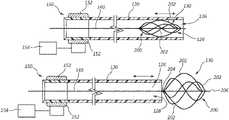
- FIG. 1illustrates a perspective view of a catheter 100 .
- the catheter 100may be configured to macerate and remove a clot, such as in vascular thrombosis.
- the catheter 100may include a handle 110 and a main tubular shaft 120 .
- the handle 110includes a control portion 112 , such as to control the catheter 100 while the catheter 100 is in use.
- the main tubular shaft 120may be at least partially inserted within the patient's circulatory system when the catheter 100 is in use.
- the main tubular shaft 120may include a distal portion 122 and a proximal portion 124 .
- the proximal portion 124may be coupled to the handle 110 .
- the distal portion 122includes an opening 126 .
- the main tubular shaft 120may include a plurality of tubular shafts, such as least one tubular shaft is within another tubular shaft. In some embodiments, the plurality of tubular shafts may be concentric.
- the main tubular shaft 120may further include a macerating element 130 disposed within a lumen of the main tubular shaft 120 .
- the macerating element 130may be configured to macerate, cut, shred, or otherwise break up a clot or other blockage in a vessel.
- the macerating element 130may be disposed near the distal portion 122 of the main tubular shaft 120 .
- the catheter 100may include an aspiration port 128 that may be configured to aspirate the area where the macerating element 130 macerates the clot and aspirates the macerated components of the clot.
- the aspiration port 128is disposed along the main tubular shaft 120 .
- the aspiration port 128may be connected to a vacuum pump or syringe, such as to provide suction to the aspiration port 128 .
- the aspiration port 128may be further configured to be an infusion port, such as to deliver drugs to a treatment site within the patient's vascular system.
- FIGS. 2A-2Billustrate the catheter 100 in which the macerating element 130 may be connected to a guidewire 140 that extends through the lumen of the main tubular shaft 120 from the proximal portion 124 to the distal portion 122 .
- the guidewire 140may be configured to be rotated by a rotational member 150 .
- the rotational member 150may include a gearing/belt system 152 and may be rotated by a motor 154 .
- the motor 154may be a DC motor that is integral to the handle 110 .
- the motor 154may be an AC motor and may be powered by an AC power source.
- the rotational member 150may be disposed within the handle 110 and the speed may be controlled by controls on the handle 110 .
- the rotational speed of the rotational member 150may be variable and may be driven by the motor 154 and may be rotated in a clockwise or counterclockwise direction.
- the rotational member 150may rotate at numerous rotational velocities, including 0-10,000 rpm.
- the rotational member 150may rotate at speeds of at least 500 rpm and up 10,000 rpm.
- the rotational member 150may rotate at speeds that range from 1,000 rpm to 5,000 rpm.
- the rotational member 150may rotate at speeds that range from 500 rpm to 2,500 rpm.
- the rotational member 150may be less than 500 rpm, and in some embodiments, less than 200 rpm.
- the rotation of the rotational member 150causes the guidewire 140 and the macerating element 130 to rotate at similar speeds and emulsify clots.
- the rotation of the macerating element 130may create mechanical aspiration, a partial vacuum, or otherwise accelerate particles toward the aspiration port 128 .
- the rotation of the macerating element 130may assist the aspiration port 128 in aspirating the components of the clot macerated by the macerating element 130 .
- the main tubular shaft 120is displaceable in the longitudinal direction of the main tubular shaft 120 .
- the usermay adjust the longitudinal placement of the main tubular shaft 120 , which may expose the macerating element 130 outside of the main tubular shaft 120 .
- the macerating element 130may be expandable and may expand to increase its diameter at least two times when the macerating element 130 is displaced outside the main tubular shaft 120 . In various embodiments, the macerating element 130 may expand to increase its diameter at least four times, five times, 10 times, 12 times, or 15 times.
- the diameter of the macerating element 130may be controlled by the rotational speed of the macerating element 130 and/or controlled by the displacement of the main tubular shaft 120 compared to the macerating element 130 . In some embodiments, the diameter of the macerating element 130 may be controlled by the user with controls in the handle 110 .
- FIGS. 2A and 2Billustrate a cross-sectional view of an exemplary macerating element, basket 200 .
- FIG. 2Aillustrates the basket 200 in a collapsed state
- FIG. 2Billustrates the basket 200 in an expanded state.
- the basket 200includes two or more struts 202 , such as extending from a first portion 204 of the basket 200 to a second portion 206 of the basket 200 .
- the basket 200includes three or more struts 202 , four or more struts 202 , or five or more struts 202 .
- the struts 202may be flexible, such as to conform to a portion of a patient's circulatory system or transition between the collapsed state and the expanded state.
- the outer or leading surface of the struts 202may be roughened and the inner surface may be smoother than the leading surface so that the leading surface of the strut 202 encounters the clot and macerates the clot.
- an outer surface of leading surface of the struts 202may be smooth and the inner surface may be rougher than the leading surface. In this embodiment, the rough surface of the struts 202 emulsifies the clot and the smooth leading surface does not injure the vessel walls.
- FIG. 2Cillustrates another embodiment of the basket 200 , which includes a propeller or blade 210 disposed within the basket 200 that rotates along with the basket 200 .
- the blade 210helps macerate, cut, shred, or otherwise break up the clot.
- the blade 210may further create a partial vacuum directed to the aspiration port 128 to aspirate the components of the clot.
- the basket 200may include multiple struts 202 .
- the struts 202may have the same height.
- the struts 202may have differing heights.
- the struts 202may have different lengths, giving the struts 202 differing heights.
- a peak (max height) of each strut 202may be disposed in different locations over the length of the struts 202 .
- the peak of some of the strutsmay be centrally disposed, the peak of other struts may be disposed near a distal end of the basket 200 , and the peak of other struts may be disposed near a proximal end of the basket 200 .
- the struts 202may be fabricated from a material that provides sufficient stiffness to macerate and emulsify the clots but flexible enough to ride over and not damage the venous or arterial structures, such as valves.
- the struts 202may be made from a memory material, such as Nitinol, so that the basket 200 achieves a predetermined shape when the basket 200 is expanded.
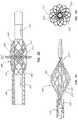
- FIG. 2Dillustrates an embodiment of a basket 200 ′ in which each strut 202 ′ has a spiral or rate of twist.
- the rate of twistextends over the length of each strut 202 ′.
- the rate of twistis a single twist over the length of the strut 202 ′.
- the rate of twistis two twists over the length of the strut 202 ′.
- the rate of twistis greater than two twists over the length of the strut 202 ′.
- the rate of twist of each strut 202 ′may help create a partial vacuum directed toward the aspiration port 128 when the basket 200 ′ is expandable and rotated.
- the rate of twist for each strut 202 ′is the same over the length of each strut 202 ′. In some embodiments, multiple struts 202 ′ may have the same rate of twist over the length of the strut 202 ′ and other struts 202 ′ may have different rates of twist.
- FIG. 2Eillustrates an embodiment of a basket 200 ′′ with a plurality of struts 202 ′′.
- the struts 202 ′′each have a first end 201 ′′ and a second end 203 ′′.
- the first end 201 ′′may be fixed to a first basket end 205 ′′ and the second end 203 ′′ may be fixed to a second basket end 207 ′′.
- the first basket end 205 ′′ and the second basket end 207 ′′may move relative to each other. For example, when the first basket end 205 ′′ moves toward the second basket end 207 ′′, the basket 200 ′′ may expand, increasing the diameter of the basket 200 ′′.
- the basket 200 ′may collapse, decreasing the diameter of the basket 200 ′′ and enabling the basket 200 ′′ to fit within the catheter 100 .
- the basket 200 ′′may have a central portion 209 ′′ that has a greater diameter than the rest of the basket 200 ′′.
- Each strut 202 ′′may spiral around the guidewire 140 .
- the first end 205 ′′is attached to the guidewire 140 and the second end 207 ′′ may be able to move relative to the guidewire 140 to enable the expansion and collapse of the basket 200 ′′.
- the second end 207 ′′may be attached to the guidewire 140 and the first end 205 ′′ may be able to move relative to the guidewire 140 .
- the struts of the different embodiments of the basketmay be flat wire, a round wire, or some struts may be flat wire and other struts may be round wire.
- FIGS. 2F-2Gillustrate an embodiment of a basket 200 ′′′ with a plurality of struts 202 ′′′.
- the struts 202 ′′′may be cut from a metal tubing in a predetermined pattern.
- the struts 202 ′′′may be cut in a vareity of different manners, for example, laser cutting, mechanical cutting, plasma cutting, flame cutting, waterjet cutting, etc.
- Each strut 202 ′′′may have a first end 201 ′′′ and a second end 203 ′′′.
- Each strut 202 ′′′may spiral around the guidewire 140 in the range of 360 degrees to 540 degrees.
- FIG. 2Gillustrates an end view of the basket 200 ′′′ illustrating the range of rotation of the struts 202 ′′′ from the first end 201 ′′′ to the second end 203 ′′′.
- FIGS. 3A and 3Billustrate a cross-sectional view of another exemplary embodiment of a macerating element, a wire wound stent 300 .
- FIG. 3Aillustrates the main tubular shaft 120 disposed within a vessel 10 and the wire wound stent 300 in a collapsed state within the main tubular shaft 120 .
- FIG. 3Billustrates the stent in an expanded state outside the main tubular shaft 120 .
- the wire wound stent 300may expand to a round cylindrical shape. The wire wound stent 300 expands when the main tubular shaft 120 is displaced relative to the longitudinal direction of the main tubular shaft 120 and exposes the wire wound stent 300 .
- the wire wound stent 300When the wire wound stent 300 is outside the main tubular shaft 120 , the wire wound stent 300 may be rotated to macerate the clot or blockage 20 . Rotation of the wire wound stent 300 may create mechanical aspiration, a partial vacuum, or otherwise accelerate clots toward the aspiration port 128 to aspirate the components of the macerated clot.
- the structure of the wire wound stent 300may include a plurality of u-shaped turns disposed throughout the wire wound stent 300 .
- the wire wound stent 300includes a plurality of rows, each row with a plurality of u-turns. In a collapsed and unexpanded state, the u-shaped turns are crimped, thus allowing the wire wound stent 300 to fit within the lumen of the main tubular shaft 120 . When the wire wound stent 300 is disposed outside the main tubular shaft 120 , the u-shaped turns expand, thus expanding the entire wire wound stent 300 .
- the wire wound stent 300is configured to expand to a predetermined size.
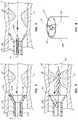
- FIGS. 4A and 4Billustrate a cross-sectional view of another exemplary embodiment of a macerating element, an s-curve stent 400 .
- FIG. 4Aillustrates the s-curve stent 400 in a collapsed state
- FIG. 4Billustrate the s-curve stent 400 in an expanded state outside the main tubular shaft 120 ′.
- the s-curve stent 400 in the expanded statemay have a round cylindrical shape.
- the main tubular shaft 120 ′includes barbs 410 that may engage with the vessel 10 to secure the main tubular shaft 120 ′ in place while the s-curve stent 400 is rotated.
- the s-curve stent 400expands when the main tubular shaft 120 ′ is displaced relative to the longitudinal direction of the main tubular shaft 120 ′ and exposes the s-curve stent 400 .
- the s-curve stent 400may be rotated to macerate the clot or blockage. Rotation of the s-curve stent 400 may create mechanical aspiration, a partial vacuum, or otherwise accelerate clots toward the aspiration port 128 to aspirate the components of the macerated clot.
- the structure of the s-curve stent 400includes a plurality of struts 402 that each include an s-curve 404 .
- the s-curves 404 of each strut 402are laterally connected to adjacent s-curves 404 by a connector 406 .
- the distal ends of each s-curve 404are coupled together at a distal end 408 .
- the proximal ends of each s-curve 404are coupled to a sheath 406 that is disposed over guidewire 140 .
- the radial expansion of the s-curve stent 400changes the structure of the s-curves 404 , creating a stretch s-curve, with the connectors 406 and the middle portion of the s-curve 404 being substantially linear.
- FIG. 5illustrates a cross-sectional view of another exemplary embodiment of a macerating element, an articulating bit 500 disposed within the main tubular shaft 120 near the distal end.
- the articulating bit 500includes multiple bits 504 a , 504 b that are attached to separate guidewires 502 a , 502 b .
- the guidewires 502 a , 502 b and bits 504 a , 504 bmay rotate about an axis of rotation A 1 .
- the articulating bit 500may be rotated to macerate the clot or blockage.
- Rotation of the articulating bit 500may further produce mechanical aspiration, a partial vacuum, or otherwise accelerate components of the clot or blockage to the aspiration port 128 .
- the main tubular shaft 120may include a scoop 129 .
- the scoop 129may extend radially away from the axis of rotation A 1 at a predetermined angle.
- the scoop 129may interface with the walls of the vessel to help prevent the articulating bit 500 from coming in contact with the vessel walls.
- the scoop 129may help keep clots from passing.
- FIG. 5illustrates two bits 504 a , 504 b , but articulating bit 500 may include more or fewer than two bits 504 a , 504 b.
- FIG. 6illustrates a cross-sectional view of another exemplary embodiment of a macerating element, an auger 600 .
- the auger 600may have a helical bit for macerating the clot or blockage.
- the auger 600may rotate about an axis of rotation A 2 .
- the auger 600may extend from the proximal portion 124 to the distal portion 122 of the main tubular shaft 120 , but not extend beyond the distal portion 122 of the main tubular shaft 120 .
- the main tubular shaft 120includes the scoop 129 .
- FIG. 7illustrates a cross-sectional view of a macerating element, an auger 700 , and a barbed guidewire 710 .
- the barbed guidewire 700may include a plurality of barbs that extend in a proximal direction at a predetermined angle from the barbed guidewire 700 .
- the displacement of the barbed guidewire 700may be controlled by the user, enabling the user to extend the barbed guidewire 700 beyond the distal portion 122 of the main tubular shaft 120 .
- the usermay extend the barbed guidewire 700 to interact with the clot or blockage and direct the clot or blockage toward auger 600 and pull the clot or blockage toward the auger 600 .
- FIG. 8illustrates an alternative embodiment of the main tubular shaft 120 ′.
- the main tubular shaft 120 ′may include an additional internal lumen 121 ′ that is disposed within the main tubular shaft 120 ′.
- the internal lumen 121 ′has a diameter less than the diameter of the main tubular shaft 120 ′.
- the diameter of the internal lumen 121 ′is half the diameter of the main tubular shaft 120 ′.
- the diameter of the internal lumen 121 ′is a fourth of the diameter of the main tubular shaft 120 ′.
- the internal lumen 121 ′may be coupled to the main tubular shaft 120 ′ by a plurality of connectors 119 ′ that extend from the internal lumen 121 ′ to the main tubular shaft 120 ′.
- the internal lumen 121 ′may house the macerating element.
- the macerating elementmay be extended beyond the distal end of the internal lumen 121 ′ to allow the macerating element to macerate the clot. As discussed previously, the macerating element may be expandable.
- the main tubular shaft 120 ′may further include an aspiration port 128 ′.
- the aspiration port 128 ′aspirates the components of the clot or blockage as the macerating element macerates the clot or blockage.
- the aspiration port 128 ′may coincide with the main tubular shaft 120 ′.
- FIGS. 9A-9Cillustrate a cross-sectional view of the main tubular shaft 120 with the macerating element 900 , such as a plurality of snare loops (discussed later in relation to FIGS. 10A-10C ), and an additional internal lumen 800 .
- the diameter of the internal lumen 800may be slightly smaller than the diameter of the main tubular shaft 120 , and the internal lumen 800 is configured to slide relative to the main tubular shaft 120 .
- FIG. 9Aillustrates the internal lumen 800 disposed completely within the main tubular shaft 120 .
- FIG. 9Billustrates a cross-sectional view of the main tubular shaft 120 and the internal lumen 800 after the internal lumen 800 has been deployed.
- a scoop 810extends away from the main tubular shaft 120 at a predetermined angle.
- the scoop 810may interact with the vessel wall and help prevent the auger 600 from damaging the vessel wall.
- the scoop 810may be similar to scoop 129 previously described.
- the scoop 810may be steerable by a user.
- the usermay be able to provide a pulling force to a portion of the internal lumen 800 to direct the direction of the scoop 810 .
- the scoop 810is directed to the top of the vessel. In this manner, the user may direct the scoop 810 toward the clot or blockage.
- FIG. 10Aillustrates a cross-sectional view of another exemplary embodiment of a macerating element, a snare loop macerating element 900 .
- the snare loop macerating element 900may include a plurality of snare loops 910 that extend the length of the main tubular shaft 120 .
- Each snare loop 910has a loop that is formed near the distal end of the snare loop 910 .
- the snare loops 910may be rotated within the main tubular shaft 120 to macerate the clot or blockage.
- the main tubular shaft 120may be displaced to deploy the snare loops 910 outside of the main tubular shaft 120 , as illustrated in FIG. 10B .
- the snare loops 910may be extended beyond the distal portion 122 of the main tubular shaft 120 .
- the usermay control the macerating diameter of the snare loop macerating element 900 .
- the macerating diameterrefers to the diameter of a circumferential path that the distal ends of the snare loops 910 travel while being rotated.
- the rotation of the snare loops 910 and the distance that the snare loops 910 are outside the main tubular shaft 120determine the macerating diameter.
- the greater the speed of rotationthe greater the macerating diameter of the snare loop macerating element 900 .
- the greater the distance the snare loop macerating element 900 is outside the main tubular shaft 120the greater the macerating diameter.
- FIG. 10Cillustrates an embodiment of a snare loop macerating element 1000 .
- Snare loops 1010may include additional weight 1020 at the tips of the snare loops 1010 .
- the wire of the snare loops 1010may have a tapered diameter at the tips of the snare loops 1010 to add additional weight at the tips.
- the tipsinclude a coating that adds additional weight to the tips of the snare loops 1010 .
- the coatingmay be a low-friction, smooth coating so that the tips of the snare loops 1010 are atraumatic to the vessel walls.
- FIGS. 11A and 11Billustrate an embodiment of a dual loop macerating element 1100 .
- FIG. 11Aillustrates the dual loop macerating element 1100 in a collapsed configuration and
- FIG. 11Billustrates the dual loop macerating element 1100 in an expanded configuration.
- the dual loop macerating element 1100may include a plurality of dual loop wires 1110 .
- the dual loop wires 1110includes two loops near the distal end of the dual loop wire 1110 .
- the usermay control the macerating diameter of the dual loop macerating element 1100 .
- the rotation of the dual loop wires 1110 and the distance that the dual loop wires 1110 are outside the main tubular shaft 120determine the macerating diameter. For example, the greater the speed of rotation, the greater the macerating diameter of the dual loop macerating element 1100 . Also, the greater the distance the dual loop macerating element 1100 is outside the main tubular shaft 120 , the greater the macerating diameter.
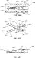
- FIGS. 12A-12Cillustrate an embodiment of a dual blade macerating element 1200 .
- the dual blade macerating element 1200 illustrated in FIGS. 12A-12Bhave two blades, a top blade 1210 and a bottom blade 1220 , forming a scissor-like shape.
- the macerating element 1200may include more than two blades.
- FIG. 12illustrates the dual blade macerating element 1200 in a collapsed configuration and disposed within the catheter 100 .
- FIG. 12Billustrates the dual blade macerating element 1200 in an expanded configuration after macerating element 1200 has been advanced out of the catheter 100 . This may be accomplished by having the catheter 100 slide back or by having the macerating element 1200 advance out of the catheter 100 .
- the macerating element 1200may include a pull hinge system 1230 .
- the pull hinge system 1230may include a housing 1232 , a pin or hinge 1234 that extends through the housing 1230 and through apertures 1216 and 1226 of each blade 1210 and 1220 .
- the apertures 1216 and 1226may have an oval shape and the hinge 1234 is slidable along the length of the apertures 1216 and 1226 .
- a usermay control the expansion of the macerating element 1200 may applying a distal or proximal oriented force to the housing 1232 of the pull hinge system 1230 .
- a distal oriented forceis applied to the housing 1232 , the hinge 1234 advances along the length of the apertures 1216 and 1226 , which causes the blades 1210 and 1220 to rotate about an axis of rotation 1240 and away from each, expanding the macerating element 1200 .
- the axis of rotationmay be a pin the extend through both blades 1210 and 1220 of the macerating element 1200 .
- FIG. 12Cillustrates the bottom blade 1220 which includes an aperture 1226 in the bottom blade 1220 for the pin 1242 to extend through, thus creating the axis of rotation for the bottom blade 1220 .
- the top blade 1210includes a similar aperture for the pin 1242 to extend through.
- a usermay collapse the macerating element 1200 by applying a proximally oriented force to the housing 1232 , which pulls the hinge 1234 along the length of the apertures 1216 and 1226 and the blades 1210 and 1220 rotate about axis of rotation 1240 and toward each other and close the macerating element 1200 .
- each blade 1210 and 1220 of the macerating element 1200may include an edge 1212 , 1222 that helps macerate, cut, shred, or otherwise break up the clot.
- the edges 1212 , 1222may be sharpened to macerate the clot or the edges 1212 , 1222 may be roughened to macerate the clot.
- the rotation of the blades 1210 and 1220may further create a partial vacuum directed to an aspiration port to aspirate the components of the clot.
- Each blade 1210 and 1220may further include an outer edge 1214 and 1224 .
- the outer edges 1214 and 1224may be smooth or include a low-friction, smooth coating so that the outer edges 1214 and 1224 are atraumatic to the vessel wall while the macerating element 1200 is rotating.
- Each blade 1210 and 1220may further include an additional aperture, such as the aperture 1228 shown in FIG. 12C .
- the aperture 1228may lighten the weight of the blade 1210 .
- Any methods disclosed hereininclude one or more steps or actions for performing the described method.
- the method steps and/or actionsmay be interchanged with one another.
- the order and/or use of specific steps and/or actionsmay be modified.
- sub-routines or only a portion of a method described hereinmay be a separate method within the scope of this disclosure. Stated otherwise, some methods may include only a portion of the steps described in a more detailed method.
Landscapes
- Health & Medical Sciences (AREA)
- Surgery (AREA)
- Life Sciences & Earth Sciences (AREA)
- Heart & Thoracic Surgery (AREA)
- Molecular Biology (AREA)
- Veterinary Medicine (AREA)
- Engineering & Computer Science (AREA)
- Biomedical Technology (AREA)
- Public Health (AREA)
- Medical Informatics (AREA)
- Nuclear Medicine, Radiotherapy & Molecular Imaging (AREA)
- Animal Behavior & Ethology (AREA)
- General Health & Medical Sciences (AREA)
- Vascular Medicine (AREA)
- Orthopedic Medicine & Surgery (AREA)
- Pathology (AREA)
- Surgical Instruments (AREA)
Abstract
Description
Claims (5)
Priority Applications (1)
| Application Number | Priority Date | Filing Date | Title |
|---|---|---|---|
| US16/563,390US11304713B2 (en) | 2018-09-07 | 2019-09-06 | Thrombosis macerating and aspiration devices for blood vessels |
Applications Claiming Priority (3)
| Application Number | Priority Date | Filing Date | Title |
|---|---|---|---|
| US201862728537P | 2018-09-07 | 2018-09-07 | |
| US201962793282P | 2019-01-16 | 2019-01-16 | |
| US16/563,390US11304713B2 (en) | 2018-09-07 | 2019-09-06 | Thrombosis macerating and aspiration devices for blood vessels |
Publications (2)
| Publication Number | Publication Date |
|---|---|
| US20200078029A1 US20200078029A1 (en) | 2020-03-12 |
| US11304713B2true US11304713B2 (en) | 2022-04-19 |
Family
ID=69719351
Family Applications (1)
| Application Number | Title | Priority Date | Filing Date |
|---|---|---|---|
| US16/563,390Active2040-01-15US11304713B2 (en) | 2018-09-07 | 2019-09-06 | Thrombosis macerating and aspiration devices for blood vessels |
Country Status (2)
| Country | Link |
|---|---|
| US (1) | US11304713B2 (en) |
| WO (1) | WO2020051468A1 (en) |
Families Citing this family (14)
| Publication number | Priority date | Publication date | Assignee | Title |
|---|---|---|---|---|
| US10238406B2 (en) | 2013-10-21 | 2019-03-26 | Inari Medical, Inc. | Methods and apparatus for treating embolism |
| CN113796927B (en) | 2015-10-23 | 2025-03-04 | 伊纳里医疗公司 | Intravascular treatment of vascular occlusion and related devices, systems and methods |
| FI3528717T3 (en) | 2016-10-24 | 2024-08-09 | Inari Medical Inc | Devices for treating vascular occlusion |
| WO2019050765A1 (en) | 2017-09-06 | 2019-03-14 | Inari Medical, Inc. | Hemostasis valves and methods of use |
| US11154314B2 (en) | 2018-01-26 | 2021-10-26 | Inari Medical, Inc. | Single insertion delivery system for treating embolism and associated systems and methods |
| WO2020160179A1 (en) | 2019-01-31 | 2020-08-06 | Merit Medical Systems, Inc. | Thrombosis macerating devices for blood vessels |
| US11986194B2 (en) | 2019-09-18 | 2024-05-21 | Merit Medical Systems, Inc. | Torque cable |
| JP7638273B2 (en) | 2019-10-16 | 2025-03-03 | イナリ メディカル, インコーポレイテッド | Systems, devices and methods for treating vascular obstructions |
| AU2021283979A1 (en)* | 2020-06-05 | 2023-01-19 | Inari Medical, Inc. | Recapturable funnel catheters, and associated systems and methods |
| CN112494111A (en)* | 2020-12-10 | 2021-03-16 | 蚌埠冠硕医疗科技有限公司 | Interventional rotational atherectomy device for arterial plaque |
| US11679195B2 (en) | 2021-04-27 | 2023-06-20 | Contego Medical, Inc. | Thrombus aspiration system and methods for controlling blood loss |
| EP4463083A1 (en) | 2022-01-11 | 2024-11-20 | Inari Medical, Inc. | Devices for removing clot material from intravascularly implanted devices, and associated systems and methods |
| US20230380850A1 (en)* | 2022-05-26 | 2023-11-30 | Neuravi Limited | Funnel aspiration catheter |
| CN118846275B (en)* | 2024-09-26 | 2024-12-17 | 四川省医学科学院·四川省人民医院 | Anticreep needle formula thorax puncture drainage device |
Citations (47)
| Publication number | Priority date | Publication date | Assignee | Title |
|---|---|---|---|---|
| US532145A (en) | 1895-01-08 | Hand-drill | ||
| US3049018A (en) | 1959-02-03 | 1962-08-14 | Lusskin Harold | Hand tool |
| US4524650A (en) | 1983-05-18 | 1985-06-25 | Marks Joel S | Squeeze-ratchet tool assembly |
| US4527650A (en) | 1983-03-18 | 1985-07-09 | Odetics, Inc. | Walking machine |
| US5213015A (en) | 1991-10-03 | 1993-05-25 | Disston Jr Horace C | Variable nut driver |
| WO2001017587A1 (en) | 1999-09-07 | 2001-03-15 | Merit Medical Systems, Inc. | Hemostasis valve apparatus with integral introducer |
| US20010031981A1 (en) | 2000-03-31 | 2001-10-18 | Evans Michael A. | Method and device for locating guidewire and treating chronic total occlusions |
| US20020029052A1 (en)* | 2000-04-07 | 2002-03-07 | Bacchus Vascular, Inc. | Methods and device for percutaneous remote endarterectomy |
| US6454779B1 (en) | 1998-04-10 | 2002-09-24 | Endicor Medical, Inc. | Rotational atherectomy device |
| US20020151918A1 (en)* | 2001-04-17 | 2002-10-17 | Scimed Life Systems, Inc. | In-stent ablative tool |
| US20020169414A1 (en) | 2000-02-01 | 2002-11-14 | Kletschka Harold D. | Embolic protection device having expandable trap |
| US20030040704A1 (en)* | 2001-08-22 | 2003-02-27 | Gerald Dorros | Apparatus and methods for treating stroke and controlling cerebral flow characteristics |
| US20050268750A1 (en) | 2004-03-30 | 2005-12-08 | Bruce Robert A | Powered surgical screwdriver |
| US7037316B2 (en) | 1997-07-24 | 2006-05-02 | Mcguckin Jr James F | Rotational thrombectomy device |
| US7220269B1 (en)* | 2003-11-06 | 2007-05-22 | Possis Medical, Inc. | Thrombectomy catheter system with occluder and method of using same |
| US20070208361A1 (en)* | 2006-03-06 | 2007-09-06 | Terumo Kabushiki Kaisha | Atherectomy catheter |
| US20080033467A1 (en)* | 2006-06-08 | 2008-02-07 | Olympus Medical Systems Corp. | Calculus crushing apparatus and medical procedure using endoscope |
| US20080125798A1 (en)* | 2006-11-08 | 2008-05-29 | Cook Incorporated | Thrombus removal device |
| US20080277445A1 (en) | 2007-05-07 | 2008-11-13 | Zergiebel Earl M | Single fire tacker instrument |
| US20090030274A1 (en) | 2006-09-15 | 2009-01-29 | Acclarent, Inc. | Endoscopic methods and devices for transnasal procedures |
| US20100023033A1 (en)* | 2008-07-25 | 2010-01-28 | Medtronic Vescular, Inc. | Hydrodynamic Thrombectomy Catheter |
| US20110282279A1 (en) | 2009-06-26 | 2011-11-17 | Becton, Dickinson And Company | Passive Reuse Prevention Syringe That Uses a Flange Lock |
| US20120059356A1 (en)* | 2010-09-07 | 2012-03-08 | Di Palma Giorgio | Device and method for removing material from a hollow anatomical structure |
| US20120239008A1 (en) | 2010-10-19 | 2012-09-20 | Distal Access, Llc | Apparatus for rotating medical devices, systems including the apparatus, and associated methods |
| US20120277671A1 (en) | 2006-12-29 | 2012-11-01 | Fuentes Allan M | Dual braid reinforcement deflectable device |
| US20120316586A1 (en) | 1999-09-17 | 2012-12-13 | Tyco Healthcare Group Lp | Mechanical pump for removal of fragmented matter and methods of manufacture and use |
| US20130289578A1 (en)* | 2012-04-13 | 2013-10-31 | Yawa-Med, Inc. | Blood clot extraction device |
| US20140142594A1 (en) | 2010-10-19 | 2014-05-22 | Distal Access, Llc | Apparatus for rotating medical devices, systems including the apparatus, and associated methods |
| US8764779B2 (en) | 2010-05-13 | 2014-07-01 | Rex Medical, L.P. | Rotational thrombectomy wire |
| US20140228869A1 (en)* | 2013-02-13 | 2014-08-14 | Medrad, Inc. | Thrombectomy catheter |
| US8808237B2 (en) | 2010-04-26 | 2014-08-19 | Joseph Michael Thielen | Expandable perfusion balloon |
| US20140277015A1 (en)* | 2013-03-14 | 2014-09-18 | Curtiss T. Stinis | Vascular plaque removal systems, devices, and methods |
| US8845621B2 (en) | 2010-10-19 | 2014-09-30 | Distal Access, Llc | Apparatus for rotating medical devices, systems including the apparatus, and associated methods |
| US20150305765A1 (en) | 2014-04-28 | 2015-10-29 | Distal Access, Llc | Tissue resectors with cutting wires, hand operated tissue resecting systems and associated methods |
| US20150314074A1 (en) | 2008-09-23 | 2015-11-05 | Becton, Dickinson And Company | Apparatus And Methods For Purging Catheter Systems |
| US20160015505A1 (en) | 2006-01-03 | 2016-01-21 | Volcano Corporation | Endoluminal filter having enhanced echogenic properties |
| US20160038174A1 (en)* | 2013-03-15 | 2016-02-11 | National University Of Ireland Galway | A device suitable for removing matter from inside the lumen and the wall of a body lumen |
| US20160066933A1 (en)* | 2014-09-10 | 2016-03-10 | Vascular Solutions, Inc. | Guidewire Capture |
| US20160270813A1 (en)* | 2015-03-20 | 2016-09-22 | Terumo Kabushiki Kaisha | Catheter system and treatment method |
| US20160331468A1 (en) | 2015-05-11 | 2016-11-17 | Veran Medical Technologies, Inc. | Adjustable length medical instrument assembly with localization elements for tracking medical instrument extension |
| US20170020556A1 (en)* | 2012-05-09 | 2017-01-26 | Fusion Medical, Inc. | Clot removal device for blood vessels |
| US20170252057A1 (en) | 2016-03-03 | 2017-09-07 | Boston Scientific Scimed, Inc. | Accessory devices for use with catheters |
| US20180126119A1 (en) | 2016-07-29 | 2018-05-10 | Sean A. McNiven | Intravascular device delivery sheath |
| WO2018148456A1 (en) | 2017-02-10 | 2018-08-16 | Texas Medical Center | Transcatheter device for interatrial anastomosis |
| US20180242989A1 (en) | 2014-12-16 | 2018-08-30 | Penumbra Inc. | Methods and Devices for Removal of Thromboembolic Material |
| US20200246029A1 (en) | 2019-01-31 | 2020-08-06 | Merit Medical Systems, Inc. | Thrombosis macerating devices for blood vessels |
| US20210077133A1 (en) | 2019-09-18 | 2021-03-18 | Merit Medical Systems, Inc. | Torque cable |
- 2019
- 2019-09-06USUS16/563,390patent/US11304713B2/enactiveActive
- 2019-09-06WOPCT/US2019/049974patent/WO2020051468A1/ennot_activeCeased
Patent Citations (49)
| Publication number | Priority date | Publication date | Assignee | Title |
|---|---|---|---|---|
| US532145A (en) | 1895-01-08 | Hand-drill | ||
| US3049018A (en) | 1959-02-03 | 1962-08-14 | Lusskin Harold | Hand tool |
| US4527650A (en) | 1983-03-18 | 1985-07-09 | Odetics, Inc. | Walking machine |
| US4524650A (en) | 1983-05-18 | 1985-06-25 | Marks Joel S | Squeeze-ratchet tool assembly |
| US5213015A (en) | 1991-10-03 | 1993-05-25 | Disston Jr Horace C | Variable nut driver |
| US7037316B2 (en) | 1997-07-24 | 2006-05-02 | Mcguckin Jr James F | Rotational thrombectomy device |
| US6454779B1 (en) | 1998-04-10 | 2002-09-24 | Endicor Medical, Inc. | Rotational atherectomy device |
| WO2001017587A1 (en) | 1999-09-07 | 2001-03-15 | Merit Medical Systems, Inc. | Hemostasis valve apparatus with integral introducer |
| US20120316586A1 (en) | 1999-09-17 | 2012-12-13 | Tyco Healthcare Group Lp | Mechanical pump for removal of fragmented matter and methods of manufacture and use |
| US20020169414A1 (en) | 2000-02-01 | 2002-11-14 | Kletschka Harold D. | Embolic protection device having expandable trap |
| US20030055445A1 (en) | 2000-03-31 | 2003-03-20 | Bacchus Vascular, Inc. | Expansible shearing catheters for thrombus and occlusive material removal |
| US20010031981A1 (en) | 2000-03-31 | 2001-10-18 | Evans Michael A. | Method and device for locating guidewire and treating chronic total occlusions |
| US20020029052A1 (en)* | 2000-04-07 | 2002-03-07 | Bacchus Vascular, Inc. | Methods and device for percutaneous remote endarterectomy |
| US20020151918A1 (en)* | 2001-04-17 | 2002-10-17 | Scimed Life Systems, Inc. | In-stent ablative tool |
| US20030040704A1 (en)* | 2001-08-22 | 2003-02-27 | Gerald Dorros | Apparatus and methods for treating stroke and controlling cerebral flow characteristics |
| US7220269B1 (en)* | 2003-11-06 | 2007-05-22 | Possis Medical, Inc. | Thrombectomy catheter system with occluder and method of using same |
| US20050268750A1 (en) | 2004-03-30 | 2005-12-08 | Bruce Robert A | Powered surgical screwdriver |
| US20160015505A1 (en) | 2006-01-03 | 2016-01-21 | Volcano Corporation | Endoluminal filter having enhanced echogenic properties |
| US20070208361A1 (en)* | 2006-03-06 | 2007-09-06 | Terumo Kabushiki Kaisha | Atherectomy catheter |
| US20080033467A1 (en)* | 2006-06-08 | 2008-02-07 | Olympus Medical Systems Corp. | Calculus crushing apparatus and medical procedure using endoscope |
| US20090030274A1 (en) | 2006-09-15 | 2009-01-29 | Acclarent, Inc. | Endoscopic methods and devices for transnasal procedures |
| US20080125798A1 (en)* | 2006-11-08 | 2008-05-29 | Cook Incorporated | Thrombus removal device |
| US20120277671A1 (en) | 2006-12-29 | 2012-11-01 | Fuentes Allan M | Dual braid reinforcement deflectable device |
| US20080277445A1 (en) | 2007-05-07 | 2008-11-13 | Zergiebel Earl M | Single fire tacker instrument |
| US20100023033A1 (en)* | 2008-07-25 | 2010-01-28 | Medtronic Vescular, Inc. | Hydrodynamic Thrombectomy Catheter |
| US20150314074A1 (en) | 2008-09-23 | 2015-11-05 | Becton, Dickinson And Company | Apparatus And Methods For Purging Catheter Systems |
| US20110282279A1 (en) | 2009-06-26 | 2011-11-17 | Becton, Dickinson And Company | Passive Reuse Prevention Syringe That Uses a Flange Lock |
| US8808237B2 (en) | 2010-04-26 | 2014-08-19 | Joseph Michael Thielen | Expandable perfusion balloon |
| US8764779B2 (en) | 2010-05-13 | 2014-07-01 | Rex Medical, L.P. | Rotational thrombectomy wire |
| US20120059356A1 (en)* | 2010-09-07 | 2012-03-08 | Di Palma Giorgio | Device and method for removing material from a hollow anatomical structure |
| US20140142594A1 (en) | 2010-10-19 | 2014-05-22 | Distal Access, Llc | Apparatus for rotating medical devices, systems including the apparatus, and associated methods |
| US20120239008A1 (en) | 2010-10-19 | 2012-09-20 | Distal Access, Llc | Apparatus for rotating medical devices, systems including the apparatus, and associated methods |
| US8845621B2 (en) | 2010-10-19 | 2014-09-30 | Distal Access, Llc | Apparatus for rotating medical devices, systems including the apparatus, and associated methods |
| US20130289578A1 (en)* | 2012-04-13 | 2013-10-31 | Yawa-Med, Inc. | Blood clot extraction device |
| US20170020556A1 (en)* | 2012-05-09 | 2017-01-26 | Fusion Medical, Inc. | Clot removal device for blood vessels |
| US20140228869A1 (en)* | 2013-02-13 | 2014-08-14 | Medrad, Inc. | Thrombectomy catheter |
| US20140277015A1 (en)* | 2013-03-14 | 2014-09-18 | Curtiss T. Stinis | Vascular plaque removal systems, devices, and methods |
| US20160038174A1 (en)* | 2013-03-15 | 2016-02-11 | National University Of Ireland Galway | A device suitable for removing matter from inside the lumen and the wall of a body lumen |
| US20180271556A1 (en) | 2013-03-15 | 2018-09-27 | National University Of Ireland Galway | Extraction devices |
| US20150305765A1 (en) | 2014-04-28 | 2015-10-29 | Distal Access, Llc | Tissue resectors with cutting wires, hand operated tissue resecting systems and associated methods |
| US20160066933A1 (en)* | 2014-09-10 | 2016-03-10 | Vascular Solutions, Inc. | Guidewire Capture |
| US20180242989A1 (en) | 2014-12-16 | 2018-08-30 | Penumbra Inc. | Methods and Devices for Removal of Thromboembolic Material |
| US20160270813A1 (en)* | 2015-03-20 | 2016-09-22 | Terumo Kabushiki Kaisha | Catheter system and treatment method |
| US20160331468A1 (en) | 2015-05-11 | 2016-11-17 | Veran Medical Technologies, Inc. | Adjustable length medical instrument assembly with localization elements for tracking medical instrument extension |
| US20170252057A1 (en) | 2016-03-03 | 2017-09-07 | Boston Scientific Scimed, Inc. | Accessory devices for use with catheters |
| US20180126119A1 (en) | 2016-07-29 | 2018-05-10 | Sean A. McNiven | Intravascular device delivery sheath |
| WO2018148456A1 (en) | 2017-02-10 | 2018-08-16 | Texas Medical Center | Transcatheter device for interatrial anastomosis |
| US20200246029A1 (en) | 2019-01-31 | 2020-08-06 | Merit Medical Systems, Inc. | Thrombosis macerating devices for blood vessels |
| US20210077133A1 (en) | 2019-09-18 | 2021-03-18 | Merit Medical Systems, Inc. | Torque cable |
Non-Patent Citations (9)
| Title |
|---|
| International Search Report and Written Opinion dated Jan. 3, 2020 for PCT/UA2019/049974. |
| International Search Report and Written Opinion dated Jan. 6, 2017 for PCT/US2016/053932. |
| International Search Report and Written Opinion dated Jun. 1, 2020 for PCT/US2020/015721. |
| International Search Report and Written Opinion dated Mar. 23, 2021 for PCT/US2020/051270. |
| Notice of Allowance dated Sep. 11, 2019 for U.S. Appl. No. 15/277,473. |
| Office Action dated Apr. 22, 2019 for U.S. Appl. No. 15/277,473. |
| Office Action dated Dec. 27, 2021 for U.S. Appl. No. 16/852,105. |
| Office Action dated Nov. 29, 2018 for U.S. Appl. No. 15/277,473. |
| SPINR Product Brochure, Rights acquired by Merit Medical Systems, Inc. ,Jul. 2015. |
Also Published As
| Publication number | Publication date |
|---|---|
| US20200078029A1 (en) | 2020-03-12 |
| WO2020051468A1 (en) | 2020-03-12 |
Similar Documents
| Publication | Publication Date | Title |
|---|---|---|
| US11304713B2 (en) | Thrombosis macerating and aspiration devices for blood vessels | |
| JP7437800B2 (en) | Methods and systems for treating acute ischemic stroke | |
| US12343036B2 (en) | Methods and systems for treatment of acute ischemic stroke | |
| US11793531B2 (en) | Axial lengthening thrombus capture system, tensioning system and expandable funnel catheter | |
| CN111031943B (en) | Fluid Dynamic Vortex Suction Catheter | |
| US10448969B2 (en) | Clot removal device for blood vessels | |
| US11376028B1 (en) | Devices, systems, and methods for removing obstructive material from body lumens | |
| US10722238B2 (en) | Clot removal device for deep vein thrombosis | |
| US20120197277A1 (en) | Vascular plaque removal systems, devices, and methods | |
| WO2001064115A2 (en) | Method and apparatus for treating vein graft lesions | |
| CN103767760A (en) | Apparatus and method for clot disruption and evacuation | |
| JP2004503265A (en) | Tensile shear catheter for thrombus and occluding material removal | |
| EP3968876B1 (en) | Atherectomy devices including positive and negative rake angle cutting blades | |
| WO2022221643A1 (en) | Devices, systems, and methods for removing obstructive material from body lumens | |
| CN115461000A (en) | Atherectomy device comprising a sealed drive shaft | |
| EP3407809B1 (en) | Clot removal device for blood vessels | |
| US20240197347A1 (en) | Devices, systems, and methods for removing obstructive material from body lumens |
Legal Events
| Date | Code | Title | Description |
|---|---|---|---|
| FEPP | Fee payment procedure | Free format text:ENTITY STATUS SET TO UNDISCOUNTED (ORIGINAL EVENT CODE: BIG.); ENTITY STATUS OF PATENT OWNER: LARGE ENTITY | |
| AS | Assignment | Owner name:MERIT MEDICAL SYSTEMS, INC., UTAH Free format text:ASSIGNMENT OF ASSIGNORS INTEREST;ASSIGNORS:HANSEN, ANDREW;HALL, JOHN;CINDRICH, CHRISTOPHER;AND OTHERS;SIGNING DATES FROM 20190225 TO 20190304;REEL/FRAME:050658/0471 | |
| STPP | Information on status: patent application and granting procedure in general | Free format text:DOCKETED NEW CASE - READY FOR EXAMINATION | |
| AS | Assignment | Owner name:WELLS FARGO BANK, NATIONAL ASSOCIATION, AS ADMINISTRATIVE AGENT, NORTH CAROLINA Free format text:SECURITY INTEREST;ASSIGNOR:MERIT MEDICAL SYSTEMS, INC.;REEL/FRAME:054899/0569 Effective date:20201218 | |
| STPP | Information on status: patent application and granting procedure in general | Free format text:NON FINAL ACTION MAILED | |
| STPP | Information on status: patent application and granting procedure in general | Free format text:RESPONSE TO NON-FINAL OFFICE ACTION ENTERED AND FORWARDED TO EXAMINER | |
| STPP | Information on status: patent application and granting procedure in general | Free format text:FINAL REJECTION MAILED | |
| STPP | Information on status: patent application and granting procedure in general | Free format text:RESPONSE AFTER FINAL ACTION FORWARDED TO EXAMINER | |
| STPP | Information on status: patent application and granting procedure in general | Free format text:NOTICE OF ALLOWANCE MAILED -- APPLICATION RECEIVED IN OFFICE OF PUBLICATIONS | |
| STPP | Information on status: patent application and granting procedure in general | Free format text:AWAITING TC RESP., ISSUE FEE NOT PAID | |
| STPP | Information on status: patent application and granting procedure in general | Free format text:NOTICE OF ALLOWANCE MAILED -- APPLICATION RECEIVED IN OFFICE OF PUBLICATIONS | |
| STPP | Information on status: patent application and granting procedure in general | Free format text:PUBLICATIONS -- ISSUE FEE PAYMENT RECEIVED | |
| STPP | Information on status: patent application and granting procedure in general | Free format text:PUBLICATIONS -- ISSUE FEE PAYMENT VERIFIED | |
| STCF | Information on status: patent grant | Free format text:PATENTED CASE | |
| MAFP | Maintenance fee payment | Free format text:PAYMENT OF MAINTENANCE FEE, 4TH YEAR, LARGE ENTITY (ORIGINAL EVENT CODE: M1551); ENTITY STATUS OF PATENT OWNER: LARGE ENTITY Year of fee payment:4 |