US11304642B2 - Multi-axial position sensors printed on a folded flexible circuit board - Google Patents
Multi-axial position sensors printed on a folded flexible circuit boardDownload PDFInfo
- Publication number
- US11304642B2 US11304642B2US15/433,072US201715433072AUS11304642B2US 11304642 B2US11304642 B2US 11304642B2US 201715433072 AUS201715433072 AUS 201715433072AUS 11304642 B2US11304642 B2US 11304642B2
- Authority
- US
- United States
- Prior art keywords
- field
- sensing coil
- flexible substrate
- axis
- sensing
- Prior art date
- Legal status (The legal status is an assumption and is not a legal conclusion. Google has not performed a legal analysis and makes no representation as to the accuracy of the status listed.)
- Active, expires
Links
Images


Classifications
- A—HUMAN NECESSITIES
- A61—MEDICAL OR VETERINARY SCIENCE; HYGIENE
- A61B—DIAGNOSIS; SURGERY; IDENTIFICATION
- A61B18/00—Surgical instruments, devices or methods for transferring non-mechanical forms of energy to or from the body
- A61B18/04—Surgical instruments, devices or methods for transferring non-mechanical forms of energy to or from the body by heating
- A61B18/12—Surgical instruments, devices or methods for transferring non-mechanical forms of energy to or from the body by heating by passing a current through the tissue to be heated, e.g. high-frequency current
- A61B18/14—Probes or electrodes therefor
- A61B18/1492—Probes or electrodes therefor having a flexible, catheter-like structure, e.g. for heart ablation
- A—HUMAN NECESSITIES
- A61—MEDICAL OR VETERINARY SCIENCE; HYGIENE
- A61B—DIAGNOSIS; SURGERY; IDENTIFICATION
- A61B5/00—Measuring for diagnostic purposes; Identification of persons
- A61B5/24—Detecting, measuring or recording bioelectric or biomagnetic signals of the body or parts thereof
- A61B5/25—Bioelectric electrodes therefor
- A61B5/279—Bioelectric electrodes therefor specially adapted for particular uses
- A61B5/28—Bioelectric electrodes therefor specially adapted for particular uses for electrocardiography [ECG]
- A61B5/283—Invasive
- A61B5/287—Holders for multiple electrodes, e.g. electrode catheters for electrophysiological study [EPS]
- A—HUMAN NECESSITIES
- A61—MEDICAL OR VETERINARY SCIENCE; HYGIENE
- A61B—DIAGNOSIS; SURGERY; IDENTIFICATION
- A61B34/00—Computer-aided surgery; Manipulators or robots specially adapted for use in surgery
- A—HUMAN NECESSITIES
- A61—MEDICAL OR VETERINARY SCIENCE; HYGIENE
- A61B—DIAGNOSIS; SURGERY; IDENTIFICATION
- A61B5/00—Measuring for diagnostic purposes; Identification of persons
- A61B5/06—Devices, other than using radiation, for detecting or locating foreign bodies ; Determining position of diagnostic devices within or on the body of the patient
- A61B5/061—Determining position of a probe within the body employing means separate from the probe, e.g. sensing internal probe position employing impedance electrodes on the surface of the body
- A61B5/062—Determining position of a probe within the body employing means separate from the probe, e.g. sensing internal probe position employing impedance electrodes on the surface of the body using magnetic field
- A—HUMAN NECESSITIES
- A61—MEDICAL OR VETERINARY SCIENCE; HYGIENE
- A61B—DIAGNOSIS; SURGERY; IDENTIFICATION
- A61B5/00—Measuring for diagnostic purposes; Identification of persons
- A61B5/24—Detecting, measuring or recording bioelectric or biomagnetic signals of the body or parts thereof
- A61B5/25—Bioelectric electrodes therefor
- A61B5/279—Bioelectric electrodes therefor specially adapted for particular uses
- A61B5/28—Bioelectric electrodes therefor specially adapted for particular uses for electrocardiography [ECG]
- A61B5/283—Invasive
- A—HUMAN NECESSITIES
- A61—MEDICAL OR VETERINARY SCIENCE; HYGIENE
- A61B—DIAGNOSIS; SURGERY; IDENTIFICATION
- A61B5/00—Measuring for diagnostic purposes; Identification of persons
- A61B5/68—Arrangements of detecting, measuring or recording means, e.g. sensors, in relation to patient
- A61B5/6846—Arrangements of detecting, measuring or recording means, e.g. sensors, in relation to patient specially adapted to be brought in contact with an internal body part, i.e. invasive
- A61B5/6847—Arrangements of detecting, measuring or recording means, e.g. sensors, in relation to patient specially adapted to be brought in contact with an internal body part, i.e. invasive mounted on an invasive device
- A61B5/6851—Guide wires
- A—HUMAN NECESSITIES
- A61—MEDICAL OR VETERINARY SCIENCE; HYGIENE
- A61B—DIAGNOSIS; SURGERY; IDENTIFICATION
- A61B5/00—Measuring for diagnostic purposes; Identification of persons
- A61B5/68—Arrangements of detecting, measuring or recording means, e.g. sensors, in relation to patient
- A61B5/6846—Arrangements of detecting, measuring or recording means, e.g. sensors, in relation to patient specially adapted to be brought in contact with an internal body part, i.e. invasive
- A61B5/6847—Arrangements of detecting, measuring or recording means, e.g. sensors, in relation to patient specially adapted to be brought in contact with an internal body part, i.e. invasive mounted on an invasive device
- A61B5/6852—Catheters
- A61B5/6859—Catheters with multiple distal splines
- H—ELECTRICITY
- H01—ELECTRIC ELEMENTS
- H01F—MAGNETS; INDUCTANCES; TRANSFORMERS; SELECTION OF MATERIALS FOR THEIR MAGNETIC PROPERTIES
- H01F41/00—Apparatus or processes specially adapted for manufacturing or assembling magnets, inductances or transformers; Apparatus or processes specially adapted for manufacturing materials characterised by their magnetic properties
- H01F41/02—Apparatus or processes specially adapted for manufacturing or assembling magnets, inductances or transformers; Apparatus or processes specially adapted for manufacturing materials characterised by their magnetic properties for manufacturing cores, coils, or magnets
- H01F41/04—Apparatus or processes specially adapted for manufacturing or assembling magnets, inductances or transformers; Apparatus or processes specially adapted for manufacturing materials characterised by their magnetic properties for manufacturing cores, coils, or magnets for manufacturing coils
- H01F41/041—Printed circuit coils
- H—ELECTRICITY
- H01—ELECTRIC ELEMENTS
- H01F—MAGNETS; INDUCTANCES; TRANSFORMERS; SELECTION OF MATERIALS FOR THEIR MAGNETIC PROPERTIES
- H01F5/00—Coils
- H01F5/003—Printed circuit coils
- H—ELECTRICITY
- H05—ELECTRIC TECHNIQUES NOT OTHERWISE PROVIDED FOR
- H05K—PRINTED CIRCUITS; CASINGS OR CONSTRUCTIONAL DETAILS OF ELECTRIC APPARATUS; MANUFACTURE OF ASSEMBLAGES OF ELECTRICAL COMPONENTS
- H05K1/00—Printed circuits
- H05K1/16—Printed circuits incorporating printed electric components, e.g. printed resistor, capacitor, inductor
- H05K1/165—Printed circuits incorporating printed electric components, e.g. printed resistor, capacitor, inductor incorporating printed inductors
- A—HUMAN NECESSITIES
- A61—MEDICAL OR VETERINARY SCIENCE; HYGIENE
- A61B—DIAGNOSIS; SURGERY; IDENTIFICATION
- A61B18/00—Surgical instruments, devices or methods for transferring non-mechanical forms of energy to or from the body
- A61B2018/00053—Mechanical features of the instrument of device
- A61B2018/0016—Energy applicators arranged in a two- or three dimensional array
- A—HUMAN NECESSITIES
- A61—MEDICAL OR VETERINARY SCIENCE; HYGIENE
- A61B—DIAGNOSIS; SURGERY; IDENTIFICATION
- A61B18/00—Surgical instruments, devices or methods for transferring non-mechanical forms of energy to or from the body
- A61B2018/00315—Surgical instruments, devices or methods for transferring non-mechanical forms of energy to or from the body for treatment of particular body parts
- A61B2018/00345—Vascular system
- A61B2018/00351—Heart
- A—HUMAN NECESSITIES
- A61—MEDICAL OR VETERINARY SCIENCE; HYGIENE
- A61B—DIAGNOSIS; SURGERY; IDENTIFICATION
- A61B18/00—Surgical instruments, devices or methods for transferring non-mechanical forms of energy to or from the body
- A61B2018/00571—Surgical instruments, devices or methods for transferring non-mechanical forms of energy to or from the body for achieving a particular surgical effect
- A61B2018/00577—Ablation
- A—HUMAN NECESSITIES
- A61—MEDICAL OR VETERINARY SCIENCE; HYGIENE
- A61B—DIAGNOSIS; SURGERY; IDENTIFICATION
- A61B34/00—Computer-aided surgery; Manipulators or robots specially adapted for use in surgery
- A61B34/20—Surgical navigation systems; Devices for tracking or guiding surgical instruments, e.g. for frameless stereotaxis
- A61B2034/2046—Tracking techniques
- A61B2034/2051—Electromagnetic tracking systems
- A—HUMAN NECESSITIES
- A61—MEDICAL OR VETERINARY SCIENCE; HYGIENE
- A61B—DIAGNOSIS; SURGERY; IDENTIFICATION
- A61B2560/00—Constructional details of operational features of apparatus; Accessories for medical measuring apparatus
- A61B2560/04—Constructional details of apparatus
- A61B2560/0462—Apparatus with built-in sensors
- A61B2560/0468—Built-in electrodes
- A—HUMAN NECESSITIES
- A61—MEDICAL OR VETERINARY SCIENCE; HYGIENE
- A61B—DIAGNOSIS; SURGERY; IDENTIFICATION
- A61B2562/00—Details of sensors; Constructional details of sensor housings or probes; Accessories for sensors
- A61B2562/02—Details of sensors specially adapted for in-vivo measurements
- A61B2562/0223—Magnetic field sensors
- A—HUMAN NECESSITIES
- A61—MEDICAL OR VETERINARY SCIENCE; HYGIENE
- A61B—DIAGNOSIS; SURGERY; IDENTIFICATION
- A61B2562/00—Details of sensors; Constructional details of sensor housings or probes; Accessories for sensors
- A61B2562/04—Arrangements of multiple sensors of the same type
- A—HUMAN NECESSITIES
- A61—MEDICAL OR VETERINARY SCIENCE; HYGIENE
- A61B—DIAGNOSIS; SURGERY; IDENTIFICATION
- A61B2562/00—Details of sensors; Constructional details of sensor housings or probes; Accessories for sensors
- A61B2562/06—Arrangements of multiple sensors of different types
- A—HUMAN NECESSITIES
- A61—MEDICAL OR VETERINARY SCIENCE; HYGIENE
- A61B—DIAGNOSIS; SURGERY; IDENTIFICATION
- A61B2562/00—Details of sensors; Constructional details of sensor housings or probes; Accessories for sensors
- A61B2562/12—Manufacturing methods specially adapted for producing sensors for in-vivo measurements
- A61B2562/125—Manufacturing methods specially adapted for producing sensors for in-vivo measurements characterised by the manufacture of electrodes
- A—HUMAN NECESSITIES
- A61—MEDICAL OR VETERINARY SCIENCE; HYGIENE
- A61B—DIAGNOSIS; SURGERY; IDENTIFICATION
- A61B2562/00—Details of sensors; Constructional details of sensor housings or probes; Accessories for sensors
- A61B2562/16—Details of sensor housings or probes; Details of structural supports for sensors
- A61B2562/164—Details of sensor housings or probes; Details of structural supports for sensors the sensor is mounted in or on a conformable substrate or carrier
- A—HUMAN NECESSITIES
- A61—MEDICAL OR VETERINARY SCIENCE; HYGIENE
- A61B—DIAGNOSIS; SURGERY; IDENTIFICATION
- A61B2562/00—Details of sensors; Constructional details of sensor housings or probes; Accessories for sensors
- A61B2562/16—Details of sensor housings or probes; Details of structural supports for sensors
- A61B2562/166—Details of sensor housings or probes; Details of structural supports for sensors the sensor is mounted on a specially adapted printed circuit board
- H—ELECTRICITY
- H01—ELECTRIC ELEMENTS
- H01F—MAGNETS; INDUCTANCES; TRANSFORMERS; SELECTION OF MATERIALS FOR THEIR MAGNETIC PROPERTIES
- H01F17/00—Fixed inductances of the signal type
- H01F17/0006—Printed inductances
- H01F2017/006—Printed inductances flexible printed inductors
- H—ELECTRICITY
- H05—ELECTRIC TECHNIQUES NOT OTHERWISE PROVIDED FOR
- H05K—PRINTED CIRCUITS; CASINGS OR CONSTRUCTIONAL DETAILS OF ELECTRIC APPARATUS; MANUFACTURE OF ASSEMBLAGES OF ELECTRICAL COMPONENTS
- H05K1/00—Printed circuits
- H05K1/02—Details
- H05K1/0277—Bendability or stretchability details
- H05K1/028—Bending or folding regions of flexible printed circuits
- H—ELECTRICITY
- H05—ELECTRIC TECHNIQUES NOT OTHERWISE PROVIDED FOR
- H05K—PRINTED CIRCUITS; CASINGS OR CONSTRUCTIONAL DETAILS OF ELECTRIC APPARATUS; MANUFACTURE OF ASSEMBLAGES OF ELECTRICAL COMPONENTS
- H05K2201/00—Indexing scheme relating to printed circuits covered by H05K1/00
- H05K2201/05—Flexible printed circuits [FPCs]
- H05K2201/051—Rolled
Definitions
- the present inventionrelates generally to medical instruments fitted with position sensors, and particularly to medical instruments in which coils of the position sensors are formed on flexible circuit boards.
- a position sensortypically comprises multiple coils. Several implementations of such coils are known in the art.
- U.S. Pat. No. 8,504,133whose disclosure is incorporated herein by reference, describes a system for sensing multiple local electrical voltages from endocardial surface of a heart.
- the systemincludes an elongate tubular member; a plurality of flexible splines having proximal portions, distal portions and medial portions therein between; an anchor for securely affixing the proximal portions of the splines; an atraumatic tip for securely affixing the distal portions of the splines; and a polymeric member including opposed a first open end and a second open end defining an open lumen therein between and an inner member surface and an outer member surface.
- U.S. Pat. No. 5,722,401whose disclosure is incorporated herein by reference, describes a catheter probe comprising a flexible elongate tubular member having proximal and distal extremities.
- An expandable assemblycapable of moving from a contracted position to an expanded position is secured to the distal extremity of the flexible elongate tubular member and is formed from at least two elongate members movable between contracted and expanded positions.
- An embodiment of the present inventionthat is described herein provides a position sensor including a flexible substrate formed into a three-dimensional (3D) shape. At least first and second field-sensing coils are formed in first and second respective layers of the flexible substrate, such that in the 3D shape the first and second field-sensing coils have first and second respective axes that are not parallel to one another.
- the flexible substrateincludes a flexible circuit board.
- the 3D shapeincludes a cylindrical shape.
- the position sensorincludes a third field-sensing coil that, in the 3D shape, has a third axis that is not parallel to any of the first and second axes.
- the third field-sensing coilis formed on a third layer of the flexible substrate.
- the first and second layersare electrically isolated from one another.
- the first and second axesare orthogonal to one another.
- the position sensorincludes one or more electrodes formed on a surface of the flexible substrate.
- the first and second coilsare configured to sense respective components of a magnetic field having different respective orientations, and to generate corresponding electrical signals indicative of the sensed components of the magnetic field.
- the position sensorincludes a ferromagnetic element, which is coupled to or adjacent to the flexible substrate and is configured to amplify at least one of the sensed components.
- a method for producing a position sensorincludes forming at least first and second field-sensing coils in first and second respective layers of a flexible substrate, such that when the substrate is formed into a three-dimensional (3D) shape, the first and second field-sensing coils have first and second respective axes that are not parallel to one another.
- the flexible substrateare formed into the 3D shape.
- FIG. 1is a schematic, pictorial illustration of a catheter tracking system, in accordance with an embodiment of the present invention
- FIG. 2Ais a schematic, pictorial illustration of a flexible substrate from which a position sensor is made, in an unfolded position, in accordance with an embodiment of the present invention.
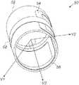
- FIG. 2Bis a schematic, pictorial illustration of a position sensor in a folded position, in accordance with an embodiment of the present invention.
- cathetersare used in a variety of therapeutic and diagnostic medical procedures, such as, for example, in cardiac electrophysiological (EP) mapping and ablation.
- Catheter distal endsmay comprise one or more position sensors.
- a position sensormay comprise multiple (e.g., three) coils arranged orthogonally to, and concentric with, one another, wound on a common form, and fitted into the distal end.
- the production of such coilsis relatively costly due to the mechanical winding of three coils.
- such a coil structureoccupies valuable volume real estate in the catheter.
- the position sensorcomprises a multi-layer flexible substrate, which is configured to be formed (e.g., folded or rolled) into a given three-dimensional (3D) shape, such as a cylindrical shape.
- the position sensorfurther comprises three field sensing coils, electrically isolated from one another, formed on three respective layers of the flexible substrate. When the substrate is formed into the given (e.g., cylindrical) shape, the axes of the three sensing coils are substantially orthogonal to one another.
- the substrate formed into the cylindrical shapehas an overall diameter that fits into the distal end of the catheter.
- the cylindrical shapeis hollow, thereby enabling threading electrical conductors or tubes through the center of the cylindrical shape.
- the cylindrical shapemay also serve as a structural component for mechanically strengthening the distal end of the catheter.
- each of the sensing coilsis configured to sense a magnetic field at a dedicated orientation, and to generate a corresponding electrical signal indicative of the sensed respective magnetic field.
- the electrical signalsmay be used for estimating the location and orientation of the catheter distal end within a patient body.
- the position sensormay further comprise a ferromagnetic element disposed on the flexible substrate, or in close proximity to the substrate, so as to increase the sensitivity of the position sensor by increasing the magnetic field amplitude sensed by the coils.
- the disclosed techniquesenable producing position sensors having multiple coils that substantially reduce the occupied volume within the distal end, and eliminate the need for mechanically winding the coils, so as to reduce the associated production costs. Furthermore, using the disclosed techniques enable customizing the shape of the position sensor so as to fit the space designated for the sensor in the distal end of the catheter.
- FIG. 1is a schematic, pictorial illustration of a catheter tracking system 20 , in accordance with an embodiment of the present invention.
- System 20comprises a probe 22 , in the present example a cardiac catheter, and a control console 24 .
- catheter 22may be used for any suitable therapeutic and/or diagnostic purposes, such as ablation of tissue in a heart 26 and the mapping of electro-cardiac signals for the diagnosis of cardiac dysfunctions, such as cardiac arrhythmias, for example.
- Console 24comprises a processor 39 , typically a general-purpose computer, with suitable front end and interface circuits for receiving signals from catheter 22 and for controlling the other components of system 20 described herein.
- Processor 39may be programmed in software to carry out the functions that are used by the system, and the processor stores data for the software in a memory 38 .
- the softwaremay be downloaded to console 24 in electronic form, over a network, for example, or it may be provided on non-transitory tangible media, such as optical, magnetic or electronic memory media. Alternatively, some or all of the functions of processor may be carried out by dedicated or programmable digital hardware components.
- An operator 30inserts catheter 22 through the vascular system of a patient 28 lying on a table 29 .
- Catheter 22comprises an insertion tube, and a distal-end assembly 40 that comprises one or more position sensors 50 shown in an inset 23 .
- Operator 30moves assembly 40 of catheter 22 in the vicinity of the target region in heart 26 by manipulating catheter 22 with a manipulator 32 near the proximal end of the catheter as shown in an inset 21 .
- the proximal end of catheter 22is connected to interface circuitry in processor 39 .
- console 24comprises a driver circuit 34 , which drives magnetic field generators 36 placed at known positions external to patient 28 lying on table 29 , e.g., below the patient's torso.
- Distal-end assembly 40typically comprises one or more position sensors 50 and, for example, one or more mapping electrodes (not shown).
- the mapping electrodesWhen the distal-end assembly is brought into contact with the inner heart surface, the mapping electrodes generate potential gradient signals in response to the sensed electrical potentials and position sensors 50 generate position signals in response to the sensed external magnetic fields, thereby enabling processor 39 to map the electrical potentials as a function of position within the heart cavity.
- the multiple position sensors and mapping electrodes in assembly 40are connected to interface circuitry in processor 39 at the catheter proximal end. Operator 30 can view the position of assembly 40 in an image 33 of heart 26 on a user display 31 .
- FIG. 2Ais a schematic, pictorial illustration of a flexible substrate from which position sensor 50 is made, in accordance with an embodiment of the present invention.
- the position sensor that is formed by forming the substrate into a cylindrical shapeis shown in FIG. 2B below.
- the upper part of FIG. 2Arepresents a top view, and the lower part of FIG. 2A represents a sectional side view, showing the structure of layers formed in the substrate.
- the substratecomprises a flexible circuit board 52 made from KaptonTM or any other suitable material.
- one or more coilssuch as coils 54 , 56 and 58 , are formed on or within layers of board 52 .
- Coils 54 , 56 and 58are made from a conductive material, such as copper, and are formed on board 52 using any suitable production technique known in the art.
- coil 54is formed on the upper surface of board 52
- coil 56is embedded within an internal layer of board 52
- coil 58is formed on the lower surface of board 52 , which is the external surface of board 52 that faces the tissue after rolling the board.
- coils 54 , 56 and 58are electrically isolated from one another by suitable dielectric layers.
- each of coils 54 , 56has a substantially symmetrical shape.
- each of coils 54 and 56has a rectangular closed-loop shape, but may alternatively have any other suitable shape.
- coil 58comprises a stripe that passes end-to-end along the board 52 .
- each of coils 54 , 56 , and 58is electrically connected to catheter 22 via electrical circuit traces (not shown) printed on board 52 .
- FIG. 2Bis a schematic, pictorial illustration of position sensor 50 in a folded position, in accordance with an embodiment of the present invention.
- axes V 1 , V 2 and V 3 of respective coils 54 , 56 and 58are substantially orthogonal to one another.
- coils 54 and 56are formed with a certain offset relative to one another on board 52 . The offset is calculated so that, after board 52 is rolled to the cylindrical shape, the two coils will be oriented with mutually-orthogonal axes.
- board 52is rolled to form a cylindrical shape having a diameter of 2 mm or any other suitable size that may fit in distal end 40 .
- the left and right edges of coil 58are coupled to one another so that coil 58 also formed a symmetrical loop along the circumference of the cylinder.
- board 52 formed into the cylindrical shapemay be used as a structural component that mechanically strengthens the wall of distal end 40 .
- the hollowed-shaped cylinderenables threading electrical conductors, tubes or other elements through the center of the cylindrical shape.
- each of coils 54 , 56 , and 58senses a magnetic field at a different orientation (depending on the axes V 1 , V 2 and V 3 ), and generates a respective electrical signal indicative of the respective sensed field.
- the electrical signals produced by coils 54 , 56 , and 58are transmitted, via assembly 40 , to processor 39 , which is configured to estimate the position of assembly 40 in heart 26 , based on the electrical signals.
- sensor 50may further comprise a ferromagnetic element (not shown) located at distal end 40 , in close proximity to coils 54 , 56 , and 58 .
- the ferromagnetic elementis configured to amplify the magnetic field sensed by coils 54 , 56 , and 58 , thereby increasing the sensitivity of sensor 50 to the magnetic fields produced by generators 36 .
- the ferromagnetic elementmay be formed on board 52 , for example, as a separate layer. In another embodiment, the ferromagnetic element may be disposed in close proximity to board 52 , for example, at the center of the volume within the cylindrical shape of board 52 (e.g., at intersection point of the axes V 1 , V 2 , and V 3 in FIG. 2B ). The size, shape, position within distal end 40 , and magnetic characteristics of the ferromagnetic element may determine the sensitivity of sensor 52 and the number of coils to be formed so as to produce the electrical signal indicative of the sensed magnetic field.
- sensor 50may further comprise one or more electrodes (not shown), such as ablation electrodes or electropotential (EP) sensors, formed on the external surface of board 52 that faces the tissue after rolling the board.
- the electrodesmay be electrically connected to catheter 22 via electrical circuit traces (not shown) printed on board 52 .
- the cylindrical shape of board 52forms a triple axes sensor (TAS) by forming coils 54 , 56 , and 58 substantially orthogonal to one another, as demonstrated by orthogonal axes V 1 , V 2 and V 3 in the figure.
- TAStriple axes sensor
- sensor 50may comprise only two coils (not shown).
- coil 54may be formed on the upper surface of board 52
- coil 56may be formed on the external surface of board 52 that faces the tissue after rolling the board, and coil 58 is omitted.
- sensor 50becomes a dual-axis sensor.
- coil 58may be formed on a separate stripe of metal, e.g., on a separate flexible board (not shown), which is formed into a cylindrical shape and coupled to board 52 (e.g., wrapped around or wrapped within) at any suitable configuration.
- coils 54 , 56 , and 58are further connected to catheter 22 (e.g., using electrical circuit traces as described in FIG.
- one or more electrodessuch as ablation electrodes or electropotential (EP) sensors, may be formed on the separate flexible board, in addition to coil 58 .
- sensor 50may comprise any suitable number of coils, having any suitable shape and arranged so that board 52 may be folded into any suitable shape, thereby arranging the axes of the coils at any angle that is not parallel with one another.
Landscapes
- Health & Medical Sciences (AREA)
- Life Sciences & Earth Sciences (AREA)
- Engineering & Computer Science (AREA)
- Surgery (AREA)
- General Health & Medical Sciences (AREA)
- Molecular Biology (AREA)
- Veterinary Medicine (AREA)
- Public Health (AREA)
- Animal Behavior & Ethology (AREA)
- Biomedical Technology (AREA)
- Heart & Thoracic Surgery (AREA)
- Medical Informatics (AREA)
- Physics & Mathematics (AREA)
- Biophysics (AREA)
- Pathology (AREA)
- Power Engineering (AREA)
- Cardiology (AREA)
- Nuclear Medicine, Radiotherapy & Molecular Imaging (AREA)
- Plasma & Fusion (AREA)
- Otolaryngology (AREA)
- Manufacturing & Machinery (AREA)
- Human Computer Interaction (AREA)
- Robotics (AREA)
- Physiology (AREA)
- Microelectronics & Electronic Packaging (AREA)
- Measurement And Recording Of Electrical Phenomena And Electrical Characteristics Of The Living Body (AREA)
- Media Introduction/Drainage Providing Device (AREA)
- Measurement Of Length, Angles, Or The Like Using Electric Or Magnetic Means (AREA)
- Transmission And Conversion Of Sensor Element Output (AREA)
- Measuring Magnetic Variables (AREA)
- Structure Of Printed Boards (AREA)
Abstract
Description
Claims (19)
Priority Applications (12)
| Application Number | Priority Date | Filing Date | Title |
|---|---|---|---|
| US15/433,072US11304642B2 (en) | 2017-02-15 | 2017-02-15 | Multi-axial position sensors printed on a folded flexible circuit board |
| IL257402AIL257402B (en) | 2017-02-15 | 2018-02-07 | Multi-axial position sensors printed on a folded flexible circuit board |
| CN201810149303.8ACN108420403B (en) | 2017-02-15 | 2018-02-13 | Multi-axial position sensor printed on a folded flexible circuit board |
| AU2018201069AAU2018201069A1 (en) | 2017-02-15 | 2018-02-14 | Multi-axial position sensors printed on a folded flexible circuit board |
| JP2018023791AJP2018151382A (en) | 2017-02-15 | 2018-02-14 | Multi-axial position sensors printed on folded flexible circuit board |
| EP21163765.7AEP3858233B1 (en) | 2017-02-15 | 2018-02-14 | Multi-axial position sensors printed on a folded flexible circuit board |
| EP24173489.6AEP4383290A3 (en) | 2017-02-15 | 2018-02-14 | Multi-axial position sensors printed on a folded flexible circuit board |
| CA2995179ACA2995179A1 (en) | 2017-02-15 | 2018-02-14 | Multi-axial position sensors printed on a folded flexible circuit board |
| EP18156795.9AEP3363359B1 (en) | 2017-02-15 | 2018-02-14 | Multi-axial position sensors printed on a folded flexible circuit board and method of producing the same |
| US17/690,051US12239447B2 (en) | 2017-02-15 | 2022-03-09 | Multi-axial position sensors printed on a folded flexible circuit board |
| JP2022164600AJP7334320B2 (en) | 2017-02-15 | 2022-10-13 | Multi-axis position sensor printed on a folded flexible circuit board |
| US19/030,797US20250160716A1 (en) | 2017-02-15 | 2025-01-17 | Multi-axial position sensors printed on a folded flexible circuit board |
Applications Claiming Priority (1)
| Application Number | Priority Date | Filing Date | Title |
|---|---|---|---|
| US15/433,072US11304642B2 (en) | 2017-02-15 | 2017-02-15 | Multi-axial position sensors printed on a folded flexible circuit board |
Related Child Applications (1)
| Application Number | Title | Priority Date | Filing Date |
|---|---|---|---|
| US17/690,051ContinuationUS12239447B2 (en) | 2017-02-15 | 2022-03-09 | Multi-axial position sensors printed on a folded flexible circuit board |
Publications (2)
| Publication Number | Publication Date |
|---|---|
| US20180228392A1 US20180228392A1 (en) | 2018-08-16 |
| US11304642B2true US11304642B2 (en) | 2022-04-19 |
Family
ID=61521288
Family Applications (3)
| Application Number | Title | Priority Date | Filing Date |
|---|---|---|---|
| US15/433,072Active2040-03-16US11304642B2 (en) | 2017-02-15 | 2017-02-15 | Multi-axial position sensors printed on a folded flexible circuit board |
| US17/690,051Active2037-09-06US12239447B2 (en) | 2017-02-15 | 2022-03-09 | Multi-axial position sensors printed on a folded flexible circuit board |
| US19/030,797PendingUS20250160716A1 (en) | 2017-02-15 | 2025-01-17 | Multi-axial position sensors printed on a folded flexible circuit board |
Family Applications After (2)
| Application Number | Title | Priority Date | Filing Date |
|---|---|---|---|
| US17/690,051Active2037-09-06US12239447B2 (en) | 2017-02-15 | 2022-03-09 | Multi-axial position sensors printed on a folded flexible circuit board |
| US19/030,797PendingUS20250160716A1 (en) | 2017-02-15 | 2025-01-17 | Multi-axial position sensors printed on a folded flexible circuit board |
Country Status (7)
| Country | Link |
|---|---|
| US (3) | US11304642B2 (en) |
| EP (3) | EP3363359B1 (en) |
| JP (2) | JP2018151382A (en) |
| CN (1) | CN108420403B (en) |
| AU (1) | AU2018201069A1 (en) |
| CA (1) | CA2995179A1 (en) |
| IL (1) | IL257402B (en) |
Cited By (6)
| Publication number | Priority date | Publication date | Assignee | Title |
|---|---|---|---|---|
| EP4393427A1 (en) | 2022-12-29 | 2024-07-03 | Biosense Webster (Israel) Ltd. | Cylindrical cage systems and methods for distributed tissue contact for mapping and ablation |
| EP4393378A2 (en) | 2022-12-29 | 2024-07-03 | Biosense Webster (Israel) Ltd. | Systems and methods for cylindrical cage mapping and ablation catheters comprising flexible circuits |
| EP4393429A2 (en) | 2022-12-29 | 2024-07-03 | Biosense Webster (Israel) Ltd. | Fractal cylindrical cage systems and methods for distributed tissue contact for mapping and ablation |
| EP4393400A1 (en) | 2022-12-29 | 2024-07-03 | Biosense Webster (Israel) Ltd. | Systems and methods for cylindrical cage mapping and ablation catheters having integrated electrodes |
| EP4393430A1 (en) | 2022-12-29 | 2024-07-03 | Biosense Webster (Israel) Ltd. | Systems and methods for cylindrical cage mapping and ablation catheters having flexible circuits |
| US12239447B2 (en) | 2017-02-15 | 2025-03-04 | Biosense Webster (Israel) Ltd. | Multi-axial position sensors printed on a folded flexible circuit board |
Families Citing this family (20)
| Publication number | Priority date | Publication date | Assignee | Title |
|---|---|---|---|---|
| US10405776B2 (en) | 2017-06-13 | 2019-09-10 | Biosense Webster (Israel) Ltd. | Positioning tool for an orthopedic implant |
| US20210093223A1 (en)* | 2018-04-06 | 2021-04-01 | King Abdullah University Of Science And Technology | Cylindrical body having a three-axis magnetic sensor |
| CN110947053B (en)* | 2018-09-27 | 2022-04-05 | 捷普科技(上海)有限公司 | Injection device |
| US11751936B2 (en)* | 2018-11-21 | 2023-09-12 | Biosense Webster (Israel) Ltd. | Configuring perimeter of balloon electrode as location sensor |
| US10980983B2 (en)* | 2018-12-28 | 2021-04-20 | Biosense Webster (Israel) Ltd. | Ear-nose-throat (ENT) hollow guide wire with balloon |
| DE102019115405A1 (en)* | 2019-06-06 | 2020-12-10 | Balluff Gmbh | Coil device and method of making a coil device |
| US11622698B2 (en)* | 2019-12-19 | 2023-04-11 | Biosense Webster (Israel) Ltd. | Selecting cursor locations on medical image using directions from distal end of probe |
| US11707341B2 (en)* | 2020-03-02 | 2023-07-25 | Biosense Webster (Israel) Ltd. | Jig for assembling a position sensor |
| US11832883B2 (en) | 2020-04-23 | 2023-12-05 | Johnson & Johnson Surgical Vision, Inc. | Using real-time images for augmented-reality visualization of an ophthalmology surgical tool |
| US12201265B2 (en) | 2020-04-23 | 2025-01-21 | Johnson & Johnson Surgical Vision, Inc. | Location pad surrounding at least part of patient eye for tracking position of a medical instrument |
| US11357594B2 (en) | 2020-08-07 | 2022-06-14 | Johnson & Johnson Surgical Vision, Inc. | Jig assembled on stereoscopic surgical microscope for applying augmented reality techniques to surgical procedures |
| US12045957B2 (en) | 2020-10-21 | 2024-07-23 | Johnson & Johnson Surgical Vision, Inc. | Visualizing an organ using multiple imaging modalities combined and displayed in virtual reality |
| CN117355252A (en) | 2021-05-19 | 2024-01-05 | 波士顿科学医学有限公司 | Magnetic field sensors for medical devices |
| US20230091133A1 (en) | 2021-09-23 | 2023-03-23 | Biosense Webster (Israel) Ltd. | Magnetic location sensor and ultrasound array on printed-circuit-board (pcb) of catheter and calibration thereof |
| US20230181241A1 (en)* | 2021-12-10 | 2023-06-15 | Biosense Webster (Israel) Ltd. | Electrical paths along flexible section of deflectable sheath |
| US20230310071A1 (en)* | 2022-04-05 | 2023-10-05 | Biosense Webster (Israel) Ltd. | Catheter with external magnetic coils |
| US20240197255A1 (en)* | 2022-12-16 | 2024-06-20 | Biosense Webster (Israel) Ltd. | Spiral sensor for physiologic signal measurement with position and tissue proximity indication |
| IL312417A (en)* | 2023-05-03 | 2024-12-01 | Biosense Webster Israel Ltd | Spiral Sensor for Physiologic Signal Measurement with Position and Tissue Proximity Indication |
| US20250082383A1 (en) | 2023-09-08 | 2025-03-13 | Biosense Webster (Israel) Ltd. | Medical device with tactile feedback for spine deployment |
| US20250082396A1 (en) | 2023-09-08 | 2025-03-13 | Biosense Webster (Israel) Ltd. | Expandable electrode assembly comprising extended distal end for a medical catheter |
Citations (29)
| Publication number | Priority date | Publication date | Assignee | Title |
|---|---|---|---|---|
| US5270656A (en)* | 1992-04-24 | 1993-12-14 | The Trustees Of The University Of Pennsylvania | Biplanar RF coils for magnetic resonance imaging or spectroscopy |
| US5391199A (en) | 1993-07-20 | 1995-02-21 | Biosense, Inc. | Apparatus and method for treating cardiac arrhythmias |
| WO1996005768A1 (en) | 1994-08-19 | 1996-02-29 | Biosense, Inc. | Medical diagnosis, treatment and imaging systems |
| US5722401A (en) | 1994-10-19 | 1998-03-03 | Cardiac Pathways Corporation | Endocardial mapping and/or ablation catheter probe |
| US5926020A (en) | 1994-11-16 | 1999-07-20 | Samson; Rock | Eddy current hybrid probe with movable magnetic field altering member |
| US6201387B1 (en)* | 1997-10-07 | 2001-03-13 | Biosense, Inc. | Miniaturized position sensor having photolithographic coils for tracking a medical probe |
| US6239724B1 (en) | 1997-12-30 | 2001-05-29 | Remon Medical Technologies, Ltd. | System and method for telemetrically providing intrabody spatial position |
| US6253770B1 (en)* | 1996-02-15 | 2001-07-03 | Biosense, Inc. | Catheter with lumen |
| US6332089B1 (en) | 1996-02-15 | 2001-12-18 | Biosense, Inc. | Medical procedures and apparatus using intrabody probes |
| US20020065455A1 (en) | 1995-01-24 | 2002-05-30 | Shlomo Ben-Haim | Medical diagnosis, treatment and imaging systems |
| US6484118B1 (en) | 2000-07-20 | 2002-11-19 | Biosense, Inc. | Electromagnetic position single axis system |
| US20030120150A1 (en) | 2001-12-21 | 2003-06-26 | Assaf Govari | Wireless position sensor |
| US6618612B1 (en) | 1996-02-15 | 2003-09-09 | Biosense, Inc. | Independently positionable transducers for location system |
| US20030187347A1 (en)* | 2001-02-15 | 2003-10-02 | Robin Medical Inc. | Endoscopic examining apparatus particularly useful in MRI, a probe useful in such apparatus, and a method of making such probe |
| US20040068178A1 (en) | 2002-09-17 | 2004-04-08 | Assaf Govari | High-gradient recursive locating system |
| US7197354B2 (en)* | 2004-06-21 | 2007-03-27 | Mediguide Ltd. | System for determining the position and orientation of a catheter |
| US20070219551A1 (en)* | 2003-09-22 | 2007-09-20 | Honour Kirk S | Medical device with flexible printed circuit |
| US7301332B2 (en) | 2005-10-06 | 2007-11-27 | Biosense Webster, Inc. | Magnetic sensor assembly |
| US20080140006A1 (en) | 2006-12-08 | 2008-06-12 | Boston Scientific Scimed, Inc. | Therapeutic catheter with displacement sensing transducer |
| US20100324412A1 (en)* | 2009-06-22 | 2010-12-23 | Assaf Govari | Catheter with obliquely-oriented coils |
| US20120172716A1 (en)* | 2010-12-30 | 2012-07-05 | Ran Sela | Electromagnetic coil sensor for a medical device |
| US20130066194A1 (en) | 2011-09-14 | 2013-03-14 | Dan Seter | Method for producing a miniature electromagnetic coil using flexible printed circuitry |
| US20130169272A1 (en)* | 2011-12-30 | 2013-07-04 | Uzi Eichler | Roll detection and six degrees of freedom sensor assembly |
| US8504133B2 (en) | 2011-04-22 | 2013-08-06 | Topera, Inc. | Basket style cardiac mapping catheter having a flexible electrode assembly and an atraumatic tip for detection of cardiac rhythm disorders |
| US8543190B2 (en) | 2010-07-30 | 2013-09-24 | Medtronic, Inc. | Inductive coil device on flexible substrate |
| US20140276004A1 (en) | 2013-03-15 | 2014-09-18 | Medtronic Navigation, Inc. | Navigated Surgical Instrument |
| US9037213B2 (en)* | 2008-01-08 | 2015-05-19 | Robin Medical Inc. | Method and apparatus to estimate location and orientation of objects during magnetic resonance imaging |
| US9095685B2 (en) | 2008-01-23 | 2015-08-04 | Mediguide Ltd. | Sensor mounted flexible guidewire |
| US10588543B2 (en)* | 2012-05-23 | 2020-03-17 | Biosense Webster (Israel), Ltd. | Position sensing using electric dipole fields |
Family Cites Families (17)
| Publication number | Priority date | Publication date | Assignee | Title |
|---|---|---|---|---|
| JP3018540B2 (en)* | 1991-03-29 | 2000-03-13 | 株式会社島津製作所 | 3-axis gradiometer |
| JP3506770B2 (en)* | 1994-04-21 | 2004-03-15 | オリンパス株式会社 | Endoscope position detection device |
| EP0895279A4 (en) | 1996-03-06 | 2006-04-19 | Hitachi Ltd | METHOD FOR PRODUCING A SEMICONDUCTOR DEVICE |
| JP2002093649A (en)* | 2000-09-12 | 2002-03-29 | Mitsubishi Materials Corp | Method of manufacturing bobbin coil and the bobbin coil |
| JP2003310570A (en)* | 2002-04-19 | 2003-11-05 | Kanazawa Inst Of Technology | Magnetic field detection coil, method of manufacturing magnetic field detection coil, combination coil for magnetic field detection, and magnetic field measurement device |
| US8046050B2 (en)* | 2004-03-05 | 2011-10-25 | Biosense Webster, Inc. | Position sensing system for orthopedic applications |
| JPWO2005096007A1 (en)* | 2004-03-31 | 2008-02-21 | 日本電気株式会社 | Magnetic field sensor |
| JP2006212187A (en)* | 2005-02-03 | 2006-08-17 | Pentax Corp | Electronic endoscope system |
| JP5347446B2 (en)* | 2008-11-18 | 2013-11-20 | 株式会社ジェイテクト | Substrate type multilayer coil and displacement sensor device |
| JP2014502911A (en)* | 2011-01-20 | 2014-02-06 | エナヴ メディカル リミテッド | System and method for estimating object location and orientation |
| US9891291B2 (en)* | 2011-08-01 | 2018-02-13 | Soreq Nuclear Research Center | Magnetic tracking system |
| EP3043735A1 (en)* | 2013-11-07 | 2016-07-20 | St. Jude Medical, Cardiology Division, Inc. | Medical device with contact force sensing tip |
| WO2015116687A1 (en)* | 2014-01-28 | 2015-08-06 | St. Jude Medical, Cardiology Division, Inc. | Elongate medical devices incorporating a flexible substrate, a sensor, and electrically-conductive traces |
| US10426555B2 (en)* | 2015-06-03 | 2019-10-01 | Covidien Lp | Medical instrument with sensor for use in a system and method for electromagnetic navigation |
| EP3331429B1 (en)* | 2015-07-06 | 2020-09-02 | Metritrack, Inc. | Sensor assembly for use with a positional tracking system and method of manufacture |
| WO2017017659A1 (en)* | 2015-07-30 | 2017-02-02 | St. Jude Medical International Holding S.A R.L. | Roll-sensing sensor assembly |
| US11304642B2 (en) | 2017-02-15 | 2022-04-19 | Biosense Webster (Israel) Ltd. | Multi-axial position sensors printed on a folded flexible circuit board |
- 2017
- 2017-02-15USUS15/433,072patent/US11304642B2/enactiveActive
- 2018
- 2018-02-07ILIL257402Apatent/IL257402B/enunknown
- 2018-02-13CNCN201810149303.8Apatent/CN108420403B/enactiveActive
- 2018-02-14EPEP18156795.9Apatent/EP3363359B1/enactiveActive
- 2018-02-14JPJP2018023791Apatent/JP2018151382A/enactivePending
- 2018-02-14EPEP24173489.6Apatent/EP4383290A3/enactivePending
- 2018-02-14AUAU2018201069Apatent/AU2018201069A1/ennot_activeAbandoned
- 2018-02-14CACA2995179Apatent/CA2995179A1/ennot_activeAbandoned
- 2018-02-14EPEP21163765.7Apatent/EP3858233B1/enactiveActive
- 2022
- 2022-03-09USUS17/690,051patent/US12239447B2/enactiveActive
- 2022-10-13JPJP2022164600Apatent/JP7334320B2/enactiveActive
- 2025
- 2025-01-17USUS19/030,797patent/US20250160716A1/enactivePending
Patent Citations (30)
| Publication number | Priority date | Publication date | Assignee | Title |
|---|---|---|---|---|
| US5270656A (en)* | 1992-04-24 | 1993-12-14 | The Trustees Of The University Of Pennsylvania | Biplanar RF coils for magnetic resonance imaging or spectroscopy |
| US5391199A (en) | 1993-07-20 | 1995-02-21 | Biosense, Inc. | Apparatus and method for treating cardiac arrhythmias |
| WO1996005768A1 (en) | 1994-08-19 | 1996-02-29 | Biosense, Inc. | Medical diagnosis, treatment and imaging systems |
| US5722401A (en) | 1994-10-19 | 1998-03-03 | Cardiac Pathways Corporation | Endocardial mapping and/or ablation catheter probe |
| US5926020A (en) | 1994-11-16 | 1999-07-20 | Samson; Rock | Eddy current hybrid probe with movable magnetic field altering member |
| US6690963B2 (en) | 1995-01-24 | 2004-02-10 | Biosense, Inc. | System for determining the location and orientation of an invasive medical instrument |
| US20020065455A1 (en) | 1995-01-24 | 2002-05-30 | Shlomo Ben-Haim | Medical diagnosis, treatment and imaging systems |
| US6253770B1 (en)* | 1996-02-15 | 2001-07-03 | Biosense, Inc. | Catheter with lumen |
| US6332089B1 (en) | 1996-02-15 | 2001-12-18 | Biosense, Inc. | Medical procedures and apparatus using intrabody probes |
| US6618612B1 (en) | 1996-02-15 | 2003-09-09 | Biosense, Inc. | Independently positionable transducers for location system |
| US6201387B1 (en)* | 1997-10-07 | 2001-03-13 | Biosense, Inc. | Miniaturized position sensor having photolithographic coils for tracking a medical probe |
| US6239724B1 (en) | 1997-12-30 | 2001-05-29 | Remon Medical Technologies, Ltd. | System and method for telemetrically providing intrabody spatial position |
| US6484118B1 (en) | 2000-07-20 | 2002-11-19 | Biosense, Inc. | Electromagnetic position single axis system |
| US20030187347A1 (en)* | 2001-02-15 | 2003-10-02 | Robin Medical Inc. | Endoscopic examining apparatus particularly useful in MRI, a probe useful in such apparatus, and a method of making such probe |
| US20030120150A1 (en) | 2001-12-21 | 2003-06-26 | Assaf Govari | Wireless position sensor |
| US20040068178A1 (en) | 2002-09-17 | 2004-04-08 | Assaf Govari | High-gradient recursive locating system |
| US20070219551A1 (en)* | 2003-09-22 | 2007-09-20 | Honour Kirk S | Medical device with flexible printed circuit |
| US7197354B2 (en)* | 2004-06-21 | 2007-03-27 | Mediguide Ltd. | System for determining the position and orientation of a catheter |
| US7301332B2 (en) | 2005-10-06 | 2007-11-27 | Biosense Webster, Inc. | Magnetic sensor assembly |
| US20080140006A1 (en) | 2006-12-08 | 2008-06-12 | Boston Scientific Scimed, Inc. | Therapeutic catheter with displacement sensing transducer |
| US9037213B2 (en)* | 2008-01-08 | 2015-05-19 | Robin Medical Inc. | Method and apparatus to estimate location and orientation of objects during magnetic resonance imaging |
| US9095685B2 (en) | 2008-01-23 | 2015-08-04 | Mediguide Ltd. | Sensor mounted flexible guidewire |
| US20100324412A1 (en)* | 2009-06-22 | 2010-12-23 | Assaf Govari | Catheter with obliquely-oriented coils |
| US8543190B2 (en) | 2010-07-30 | 2013-09-24 | Medtronic, Inc. | Inductive coil device on flexible substrate |
| US20120172716A1 (en)* | 2010-12-30 | 2012-07-05 | Ran Sela | Electromagnetic coil sensor for a medical device |
| US8504133B2 (en) | 2011-04-22 | 2013-08-06 | Topera, Inc. | Basket style cardiac mapping catheter having a flexible electrode assembly and an atraumatic tip for detection of cardiac rhythm disorders |
| US20130066194A1 (en) | 2011-09-14 | 2013-03-14 | Dan Seter | Method for producing a miniature electromagnetic coil using flexible printed circuitry |
| US20130169272A1 (en)* | 2011-12-30 | 2013-07-04 | Uzi Eichler | Roll detection and six degrees of freedom sensor assembly |
| US10588543B2 (en)* | 2012-05-23 | 2020-03-17 | Biosense Webster (Israel), Ltd. | Position sensing using electric dipole fields |
| US20140276004A1 (en) | 2013-03-15 | 2014-09-18 | Medtronic Navigation, Inc. | Navigated Surgical Instrument |
Non-Patent Citations (5)
| Title |
|---|
| Chinese Office Action dated Dec. 3, 2021, for Application No. 201810149303.8, 4 pages. |
| European Examination Report dated Dec. 17, 2019 for Application No. EP 18156795.9, 7 pgs. |
| European Search Report and Written Opinion dated Jun. 28, 2018 for Application No. EP 18156795.9, 9 pgs. |
| Extended European Search Report dated Jul. 5, 2021, for Application No. 21163765.7, 10 pages. |
| Japanese Office Action dated Dec. 7, 2021, for Application No. 2018-023791, 5 pages. |
Cited By (6)
| Publication number | Priority date | Publication date | Assignee | Title |
|---|---|---|---|---|
| US12239447B2 (en) | 2017-02-15 | 2025-03-04 | Biosense Webster (Israel) Ltd. | Multi-axial position sensors printed on a folded flexible circuit board |
| EP4393427A1 (en) | 2022-12-29 | 2024-07-03 | Biosense Webster (Israel) Ltd. | Cylindrical cage systems and methods for distributed tissue contact for mapping and ablation |
| EP4393378A2 (en) | 2022-12-29 | 2024-07-03 | Biosense Webster (Israel) Ltd. | Systems and methods for cylindrical cage mapping and ablation catheters comprising flexible circuits |
| EP4393429A2 (en) | 2022-12-29 | 2024-07-03 | Biosense Webster (Israel) Ltd. | Fractal cylindrical cage systems and methods for distributed tissue contact for mapping and ablation |
| EP4393400A1 (en) | 2022-12-29 | 2024-07-03 | Biosense Webster (Israel) Ltd. | Systems and methods for cylindrical cage mapping and ablation catheters having integrated electrodes |
| EP4393430A1 (en) | 2022-12-29 | 2024-07-03 | Biosense Webster (Israel) Ltd. | Systems and methods for cylindrical cage mapping and ablation catheters having flexible circuits |
Also Published As
| Publication number | Publication date |
|---|---|
| CN108420403A (en) | 2018-08-21 |
| CA2995179A1 (en) | 2018-08-15 |
| US20250160716A1 (en) | 2025-05-22 |
| EP3858233B1 (en) | 2024-05-01 |
| EP3858233C0 (en) | 2024-05-01 |
| JP7334320B2 (en) | 2023-08-28 |
| EP4383290A3 (en) | 2024-08-21 |
| IL257402A (en) | 2018-03-29 |
| IL257402B (en) | 2021-10-31 |
| US20180228392A1 (en) | 2018-08-16 |
| JP2022183239A (en) | 2022-12-08 |
| AU2018201069A1 (en) | 2018-08-30 |
| CN108420403B (en) | 2023-01-20 |
| US12239447B2 (en) | 2025-03-04 |
| US20220265194A1 (en) | 2022-08-25 |
| EP3363359B1 (en) | 2021-06-09 |
| EP4383290A2 (en) | 2024-06-12 |
| EP3858233A1 (en) | 2021-08-04 |
| JP2018151382A (en) | 2018-09-27 |
| EP3363359A1 (en) | 2018-08-22 |
Similar Documents
| Publication | Publication Date | Title |
|---|---|---|
| US12239447B2 (en) | Multi-axial position sensors printed on a folded flexible circuit board | |
| US12150751B2 (en) | Catheter splines with embedded circuit elements | |
| EP2915498B1 (en) | Multi-arm catheter with signal transmission over braid wires | |
| EP2737869B1 (en) | Device for location sensing using a local coordinate system | |
| US20250120019A1 (en) | Catheter with flexible substrate for minimizing magnetic interference | |
| US12295715B2 (en) | Multi-layer flat coil magnetic transmitters | |
| US12082875B2 (en) | Balloon catheter having a coil for sensing tissue temperature and position of the balloon |
Legal Events
| Date | Code | Title | Description |
|---|---|---|---|
| AS | Assignment | Owner name:BIOSENSE WEBSTER (ISRAEL) LTD., ISRAEL Free format text:ASSIGNMENT OF ASSIGNORS INTEREST;ASSIGNORS:GOVARI, ASSAF;BAR-TAL, MEIR;REUVENI, AVI;SIGNING DATES FROM 20170307 TO 20170321;REEL/FRAME:041703/0949 | |
| STPP | Information on status: patent application and granting procedure in general | Free format text:DOCKETED NEW CASE - READY FOR EXAMINATION | |
| STPP | Information on status: patent application and granting procedure in general | Free format text:FINAL REJECTION MAILED | |
| STPP | Information on status: patent application and granting procedure in general | Free format text:DOCKETED NEW CASE - READY FOR EXAMINATION | |
| STPP | Information on status: patent application and granting procedure in general | Free format text:NON FINAL ACTION MAILED | |
| STPP | Information on status: patent application and granting procedure in general | Free format text:RESPONSE TO NON-FINAL OFFICE ACTION ENTERED AND FORWARDED TO EXAMINER | |
| STPP | Information on status: patent application and granting procedure in general | Free format text:NOTICE OF ALLOWANCE MAILED -- APPLICATION RECEIVED IN OFFICE OF PUBLICATIONS | |
| STPP | Information on status: patent application and granting procedure in general | Free format text:AWAITING TC RESP., ISSUE FEE NOT PAID | |
| STPP | Information on status: patent application and granting procedure in general | Free format text:NOTICE OF ALLOWANCE MAILED -- APPLICATION RECEIVED IN OFFICE OF PUBLICATIONS | |
| STPP | Information on status: patent application and granting procedure in general | Free format text:DOCKETED NEW CASE - READY FOR EXAMINATION | |
| STPP | Information on status: patent application and granting procedure in general | Free format text:NOTICE OF ALLOWANCE MAILED -- APPLICATION RECEIVED IN OFFICE OF PUBLICATIONS | |
| STPP | Information on status: patent application and granting procedure in general | Free format text:AWAITING TC RESP., ISSUE FEE NOT PAID | |
| STPP | Information on status: patent application and granting procedure in general | Free format text:AWAITING TC RESP, ISSUE FEE PAYMENT RECEIVED | |
| STPP | Information on status: patent application and granting procedure in general | Free format text:PUBLICATIONS -- ISSUE FEE PAYMENT VERIFIED | |
| STCF | Information on status: patent grant | Free format text:PATENTED CASE | |
| MAFP | Maintenance fee payment | Free format text:PAYMENT OF MAINTENANCE FEE, 4TH YEAR, LARGE ENTITY (ORIGINAL EVENT CODE: M1551); ENTITY STATUS OF PATENT OWNER: LARGE ENTITY Year of fee payment:4 |