US11304521B2 - Arrangement of a pull-out guide, a rail synchronization device, and a driver - Google Patents
Arrangement of a pull-out guide, a rail synchronization device, and a driverDownload PDFInfo
- Publication number
- US11304521B2 US11304521B2US16/945,005US202016945005AUS11304521B2US 11304521 B2US11304521 B2US 11304521B2US 202016945005 AUS202016945005 AUS 202016945005AUS 11304521 B2US11304521 B2US 11304521B2
- Authority
- US
- United States
- Prior art keywords
- rail
- entrainment
- toothed rack
- toothed
- arrangement according
- Prior art date
- Legal status (The legal status is an assumption and is not a legal conclusion. Google has not performed a legal analysis and makes no representation as to the accuracy of the status listed.)
- Active
Links
Images


Classifications
- A—HUMAN NECESSITIES
- A47—FURNITURE; DOMESTIC ARTICLES OR APPLIANCES; COFFEE MILLS; SPICE MILLS; SUCTION CLEANERS IN GENERAL
- A47B—TABLES; DESKS; OFFICE FURNITURE; CABINETS; DRAWERS; GENERAL DETAILS OF FURNITURE
- A47B88/00—Drawers for tables, cabinets or like furniture; Guides for drawers
- A47B88/40—Sliding drawers; Slides or guides therefor
- A47B88/453—Actuated drawers
- A—HUMAN NECESSITIES
- A47—FURNITURE; DOMESTIC ARTICLES OR APPLIANCES; COFFEE MILLS; SPICE MILLS; SUCTION CLEANERS IN GENERAL
- A47B—TABLES; DESKS; OFFICE FURNITURE; CABINETS; DRAWERS; GENERAL DETAILS OF FURNITURE
- A47B88/00—Drawers for tables, cabinets or like furniture; Guides for drawers
- A47B88/40—Sliding drawers; Slides or guides therefor
- A47B88/44—Sequencing or synchronisation of drawer slides or functional units
- A47B88/45—Synchronisation of cooperating drawer slides, i.e. with a coordination of the rail movement of different drawer slides
- A—HUMAN NECESSITIES
- A47—FURNITURE; DOMESTIC ARTICLES OR APPLIANCES; COFFEE MILLS; SPICE MILLS; SUCTION CLEANERS IN GENERAL
- A47B—TABLES; DESKS; OFFICE FURNITURE; CABINETS; DRAWERS; GENERAL DETAILS OF FURNITURE
- A47B88/00—Drawers for tables, cabinets or like furniture; Guides for drawers
- A47B88/40—Sliding drawers; Slides or guides therefor
- A47B88/453—Actuated drawers
- A47B88/46—Actuated drawers operated by mechanically-stored energy, e.g. by springs
- A47B88/463—Actuated drawers operated by mechanically-stored energy, e.g. by springs self-opening
- A—HUMAN NECESSITIES
- A47—FURNITURE; DOMESTIC ARTICLES OR APPLIANCES; COFFEE MILLS; SPICE MILLS; SUCTION CLEANERS IN GENERAL
- A47B—TABLES; DESKS; OFFICE FURNITURE; CABINETS; DRAWERS; GENERAL DETAILS OF FURNITURE
- A47B88/00—Drawers for tables, cabinets or like furniture; Guides for drawers
- A47B88/40—Sliding drawers; Slides or guides therefor
- A47B88/497—Sliding drawers; Slides or guides therefor with other guiding mechanisms, e.g. scissor mechanisms
- A—HUMAN NECESSITIES
- A47—FURNITURE; DOMESTIC ARTICLES OR APPLIANCES; COFFEE MILLS; SPICE MILLS; SUCTION CLEANERS IN GENERAL
- A47B—TABLES; DESKS; OFFICE FURNITURE; CABINETS; DRAWERS; GENERAL DETAILS OF FURNITURE
- A47B2210/00—General construction of drawers, guides and guide devices
- A47B2210/0002—Guide construction for drawers
- A47B2210/0064—Guide sequencing or synchronisation
- A47B2210/0078—Drawers with parallel guidance or synchronization by pinion-shaft linkages
Definitions
- the inventionconcerns an arrangement comprising an extension guide that can be fastened to an item of furniture.
- the extension guidecomprises a first rail and a second rail movably mounted on the first rail.
- a rail synchronization deviceincludes a toothed rack connected to the first rail, a toothed wheel meshing with the toothed rack, and a bearing block connected to the second rail, with the toothed wheel rotatably mounted in the bearing block.
- An entrainment memberis also provided for a drawer drive device.
- the inventionconcerns an item of furniture comprising such an arrangement.
- Rail synchronization devicesare usually used in order to synchronize the movement of two rail systems arranged opposite to each other on an item of furniture. As a consequence, a precise parallel guiding of a pull-out drawer is possible. This parallel guiding relative to the furniture carcass is particularly advantageous if very narrow or very broad drawers shall be moved, wherein a lateral canting of the drawer can be substantially prevented by the parallel guiding.
- Such systemsare known to a person skilled in the art as systems for lateral stabilization. Examples are disclosed in the EP 1 036 526 A1 and in the EP 2 515 710 Bl.
- drawer drive deviceshave been known for many years by way of which a drawer is ejected or retracted. Such drawer drive devices can act directly on the drawer. Usually, however, a so-called entrainment member is associated to the drawer or to the furniture carcass which entrainment member can be brought into engagement with the drawer drive device.
- An example of such a drive deviceis disclosed in WO 2015/192153 A1.
- the object of the present inventionis to provide an improved arrangement compared to the prior art.
- the space requirementshall be as low as possible.
- as few components and material as possibleshall be needed.
- the toothed rack of the rail synchronization deviceis connected to the driver (entrainment member).
- the toothed rackis no longer (only) connected to the first rail, but the available entrainment member is used as a connection possibility for the toothed rack of the rail synchronization device.
- a first exemplary embodiment concerning the general arranging of the components of the rail synchronization deviceprovides that the first rail is in the form of a drawer rail which can be fastened to a drawer, and the second rail is in the form of a carcass rail which can be fastened to a furniture carcass.
- the bearing blockis associated with the carcass rail and, thus, is fixed relative to the furniture carcass, whereas the toothed racked is movable together with the drawer rail.
- the entrainment memberis associated with the drawer rail or directly to the drawer.
- the first railis formed as a carcass rail that can be fastened to a furniture carcass and the second rail is formed as a drawer rail that can be fastened to a drawer.
- the entrainment memberis associated to the carcass rail or directly to the furniture carcass.
- a rail systemonly comprises the first rail and the second rail.
- a central railcan also be arranged between the first rail and the second rail.
- the arrangementcomprises two extension guides (with a first rail and a second rail each) which can be fastened to opposite sides of the furniture carcass, as well as a rail synchronization device each and an entrainment member each.
- these components of the arrangementare arranged and formed mirror-symmetrically to each other on the two sides.
- the rail synchronization devicecomprises synchronization rod which is connected to the toothed wheel and which is rotating together with the toothed wheel.
- This synchronization rodis connecting and synchronizing the toothed wheels arranged on opposite sides of the furniture carcass.
- the toothed rackis only formed as a, preferably integrally formed, toothed bar.
- the toothed rackcomprises an elongated toothed bar—preferably oriented in the longitudinal direction of the extension guide—and a first holding element, preferably made of plastic.
- the toothed barrests on the entrainment member (indirectly) by means of the first holding element.
- a guiding groove for the toothed baris formed in the holding element.
- the toothed baris fixed to the first holding element in longitudinal direction.
- a fixing protrusioncan be formed on the first holding element.
- the toothed rackcomprises a second holding element, preferably made of plastic.
- the toothed baris connected to the first rail (indirectly) by the second holding element.
- This second holding elementis preferably formed in such a way that it can be inserted into the profile of the first rail.
- the toothed baris guided displaceably in a longitudinal direction on the second holding element. As a consequence, tensions or bulges can be prevented.
- the bearing blockis detachably mounted to the second rail by a, preferably lever-formed, locking element.
- the connectioncan be carried out for example by a clamping, wedging or by latching.
- the entrainment membershould be formed in such a way that it can be brought in engagement with the drawer drive device.
- the entrainment memberpreferably comprises an entrainment plate which can be connected to the first rail and an entrainment pin which is arranged on the entrainment plate.
- the entrainment platecan also be connectable directly with the furniture carcass or—in the case of a mechanical reversal—directly with the drawer.
- the toothed rackrests—preferably indirectly by means of the first holding element—on the entrainment plate of the entrainment member.
- a distribution package of the arrangement according to the inventiondoes not yet necessarily include a drawer drive device.
- the entrainment memberis already part of the arrangement, even if in the assembled state this entrainment member is not needed actually.
- This connection of the extension guide with the entrainment memberis included particularly for the reduction of storage costs if no drawer drive device at all is used in the end.
- an entrainment memberis always part of the arrangement in order to have little storage effort by having fewer different variants for storage.
- the arrangementalso comprises a drawer drive device which can be engaged with the entrainment member, preferably with its entrainment pin.
- two drawer drive devicesare arranged on opposite sides of the furniture carcass.
- these two drawer drive devicescan be synchronized by a drive device synchronization device which is separate from the rail synchronization device.
- the drawer drive devicecan be associated to the drawer or the furniture carcass.
- the entrainment memberis associated to the respective counterpart.
- the drawer drive deviceis, preferably detachably, connected with the second rail.
- the drawer drive deviceis formed as an ejection device for ejecting the drawer from a closed position into an open position.
- the drawer drive devicecan be formed as a, preferably damped, retraction device for retracting the drawer from an open position into the closed position.
- the ejection devicecomprises a carrier, preferably fastened to the second rail, an ejection element which is movable relative to the carrier, and an ejection force storage member which on the one hand is attached to the carrier and on the other hand is attached to the ejection element.
- the ejection devicecomprises a locking device which can be unlocked by over-pressing the drawer in closing direction.
- the locking devicefor example, comprises a cardioid-shaped locking guide path with a latching recess, wherein the ejection element can be locked in the latching recess by a control pin.
- Protectionis also sought for an item of furniture comprising a furniture carcass, at least one drawer and an arrangement according to the invention.
- FIG. 1is a perspective view an item of furniture with drawers and an extension guide together with a rail synchronization device
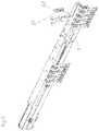
- FIG. 2is a perspective exploded view of an arrangement comprising a rail synchronization device, an extension guide, an entrainment member and a drawer drive device,
- FIG. 3shows the arrangement according to FIG. 2 in an assembled state
- FIG. 4-16show the mounting process of the arrangement in different perspective illustrations together with details
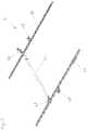
- FIG. 17shows the rail synchronization device in a perspective illustration.
- FIG. 1shows a perspective illustration of an item of furniture 10 with a cabinet-formed furniture carcass 11 , wherein drawers 12 are movably supported by extension guides 3 (can also be referred to as rail systems) relative to the furniture carcass 11 .
- the two below illustrated drawers 12are each situated in a closed position SS.
- Concerning the upper drawer 12 (not illustrated) the second rails 2 (drawer rails) of the extension guides 3are each situated in the extended state which would correspond to an open position OS of the drawer 12 .
- An extension guide 3is located on each side of the drawer 12 , and the two extension guides 3 are fastened to opposite lateral walls of the furniture carcass 11 .
- a synchronization rod 44is shown which runs transversely to the longitudinal direction L of the extension guide 3 .
- this synchronization rod 44is formed as a torsion shaft.
- the movements of the two extension guides 3can be synchronized relative to each other by the synchronization rod 44 , whereby a precise parallel guiding of the drawer 12 relative to the furniture carcass 11 can also be established.
- the two extension guides 3each comprise a (preferably metallic) first rail 1 (carcass rail) which is to be fastened to a furniture carcass 11 as well as at least one (preferably metallic) second rail 2 (drawer rail) which is movable relative to the first rail 1 or which is movably supported on the first rail 1 respectively.
- the purpose of the synchronization rod 44is to synchronize the movement of the left and right drawer rail relative to each other so that the drawer 12 can be extended from the furniture carcass 11 and can be pushed inwards without a lateral canting.
- the synchronization rod 44is rotatably supported on both sides in a bearing block 43 .
- the bearing block 43is, preferably detachably, connected to the second rail 2 .
- the synchronization rod 44On each end region, the synchronization rod 44 has a toothed wheel 42 which meshes with a toothed rack 41 .
- toothed rack 41on the drawer 12 or on the second rail 2 and to support the corresponding toothed wheel 42 together with the bearing block 43 and the synchronization rod 44 on the first rail 1 or on the furniture carcass 11 .
- the toothed rack 41 , the toothed wheel 42 , the bearing block 43 , and the synchronization rod 44together form the rail synchronization device 4 .
- FIG. 2An arrangement 100 is illustrated in FIG. 2 in a perspective exploded view.
- This arrangement 100comprises the rail synchronization device 4 , the extension guide 3 , and the entrainment member 5 .
- the arrangement 100additionally comprises a drawer drive device 6 .
- the drawer synchronization device 4comprises the only partially illustrated synchronization rod 44 , the bearing block 43 , the toothed wheel 42 and the toothed rack 41 .
- the locking element 49 movably supported on the bearing block 43is visible.
- the second holding element 48is visible as well.
- the extension guide 3comprises the first rail 1 and the second rail 2 .
- the entrainment member 5comprises a, preferably metallic, entrainment plate 51 and the entrainment pin 52 .
- the entrainment pin 52can be formed in one piece with the entrainment plate 51 .
- the entrainment pin 52is part of an attaching part, preferably made of plastic, which is connected to the entrainment plate 51 .
- the carrier 61is visible from the drawer drive device 6 —which in this case is formed as an ejection device—mainly the carrier 61 is visible.
- this drawer drive device 6comprises a synchronization rod 62 which is separate from the rail synchronization device 4 .
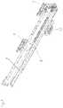
- FIG. 3the arrangement 100 is illustrated in the assembled state.
- the rail synchronization device 4is fastened to a backward (rear) region of the second rail 2 by the bearing block 43 .
- the toothed wheel 42meshes with the (not yet cut-to-length) toothed rack 41 .
- the drawer drive device 6is, preferably detachably, connected with the extension guide 3 (in particular, with the container rail of the second rail 2 ) by the carrier 61 .
- the first rail 1comprises two angular mounting elements 7 and the rail-shaped guiding part 8 . These elements are connected, preferably welded or riveted, with each other.
- the second rail 2is movably supported on the guiding part 8 of the first rail by not illustrated rolls.
- the entrainment plate 51is still distanced from the extension guide 3 .
- the guiding element 53 of the entrainment member 5is inserted into the recess 9 formed in the first rail 1 .
- the attaching part comprising the entrainment pin 52is fastened to the entrainment plate 51 .
- FIG. 6shows the position after the entrainment member 5 has been swivelled relative to the extension guide 3 .
- the entrainment member 5is fastened, preferably by clamping, to the first rail 1 of the extension guide 3 .
- FIG. 7the FIG. 6 is illustrated obliquely from above.
- the entrainment pin 52 of the entrainment member 5is visible as well.
- the first holding element 46preferably made of plastic, of the rail synchronization device 4 is illustrated additionally.
- FIG. 9shows the position when the first holding element 46 is fastened, preferably snapped or clipped, to the first rail 1 and the entrainment member 5 in the region of the entrainment member 5 . As a consequence, the first holding element 46 rests directly on the entrainment member 5 .
- the second holding element 48is illustrated. This second holding element 48 in this position encompasses the second rail 2 . In the detail illustrated bottom left, this second holding element 48 is illustrated obliquely from below.
- the second holding element 48has been shifted in longitudinal direction L opposite to the closing direction SR.
- the second holding element 48 on the one handencompasses the second rail 2 and on the other hand is held, preferably snapped, on the end region of the first rail 1 .
- thisis also illustrated in a view obliquely from below.
- the bearing block 43is attached to the backward region of the extension guide 3 .
- the locking element 49is still situated in a released position (as it is also visible in the detail bottom left).
- the locking element 49has been swivelled.
- the bearing block 43 of the rail synchronization device 4is firmly attached to the second rail 2 , and preferably clamped to the second rail 2 .
- thisis also visible, and the synchronization rod 44 and the toothed wheel 42 (connected to the synchronization rod 44 in a torque-proofed manner) is illustrated relatively large.
- the lateral guiding recesses 40 in the bottom region of the bearing block 43are visible well in this detail.
- the toothed bar 45 of the toothed rack 41has been inserted into the bearing block 43 by the guiding recesses 40 .
- the individual teeth of the toothed bar 45mesh with the toothed wheel 42 .
- the toothed bar 45also already contacts the corresponding guiding recesses in the second holding element 48 .
- the toothed bar 45is fully inserted into and also rests on the first holding element 46 .
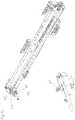
- the arrangement 100is illustrated in the assembled state.
- the toothed bar 45 together with the first holding element 46forms the toothed rack 41 .
- the toothed rack 41 of the rail synchronization device 4is connected to the entrainment member 5 .
- the toothed rack 41rests on the entrainment plate 51 of the entrainment member 5 .
- the entrainment member 5(if the arrangement 100 also comprises a drawer drive device 6 —has a dual function (to support the toothed rack 41 and serve as an engagement location for the drive device).
- FIG. 16 and the corresponding detailsit is still visible that the toothed bar 45 is guided in a shiftable manner in the longitudinal direction in the region of the second holding element 48 (see detail top right), whereas the toothed bar 45 is fixed on the first holding element 46 of the toothed rack 41 against a movement in the longitudinal direction L (see detail bottom left).
- a latching groove 13is formed in the toothed bar 45 and a corresponding latching protrusion 14 is formed in the first holding element 46 . Where applicable, this could be formed the other way round.
- the rail synchronization device 4is illustrated without an extension guide 3 .
- the toothed racks 41 arranged on both sides (see toothed bar 45 ) and the bearing blocks 43 as well as the synchronization rod 44are illustrated.
- a parallel guiding of the second rails 2 (drawer rails) of the two extension guides 3is enabled. This is often termed as a lateral stabilization.
Landscapes
- Engineering & Computer Science (AREA)
- Mechanical Engineering (AREA)
- Drawers Of Furniture (AREA)
- Lift-Guide Devices, And Elevator Ropes And Cables (AREA)
- Paper (AREA)
- Window Of Vehicle (AREA)
Abstract
Description
- 1 first rail
- 2 second rail
- 3 extension guide
- 4 rail synchronization device
- 5 entrainment member
- 6 drawer drive device
- 7 mounting elements
- 8 guiding part
- 9 recess
- 10 item of furniture
- 11 furniture carcass
- 12 drawer
- 13 latching groove
- 14 latching protrusion
- 40 guiding recesses
- 41 toothed rack
- 42 toothed wheel
- 43 bearing block
- 44 synchronization rod
- 45 toothed bar
- 46 first holding element
- 47 guiding groove
- 48 second holding element
- 49 locking element
- 51 entrainment plate
- 52 entrainment pin
- 53 guiding element
- 61 carrier
- 62 synchronization rod
- 100 arrangement
- L longitudinal direction
- SS closed position
- OS open position
- SR closing direction
Claims (22)
Applications Claiming Priority (3)
| Application Number | Priority Date | Filing Date | Title |
|---|---|---|---|
| ATA50100/2018AAT520817B1 (en) | 2018-02-01 | 2018-02-01 | Arrangement of pull-out guide, rail synchronization device and driver |
| ATA50100/2018 | 2018-02-01 | ||
| PCT/AT2019/060026WO2019148223A1 (en) | 2018-02-01 | 2019-01-23 | Arrangement of a pull-out guide, a rail synchronization device, and a driver |
Related Parent Applications (1)
| Application Number | Title | Priority Date | Filing Date |
|---|---|---|---|
| PCT/AT2019/060026ContinuationWO2019148223A1 (en) | 2018-02-01 | 2019-01-23 | Arrangement of a pull-out guide, a rail synchronization device, and a driver |
Publications (2)
| Publication Number | Publication Date |
|---|---|
| US20200359790A1 US20200359790A1 (en) | 2020-11-19 |
| US11304521B2true US11304521B2 (en) | 2022-04-19 |
Family
ID=65408829
Family Applications (1)
| Application Number | Title | Priority Date | Filing Date |
|---|---|---|---|
| US16/945,005ActiveUS11304521B2 (en) | 2018-02-01 | 2020-07-31 | Arrangement of a pull-out guide, a rail synchronization device, and a driver |
Country Status (9)
| Country | Link |
|---|---|
| US (1) | US11304521B2 (en) |
| EP (2) | EP4039132A1 (en) |
| JP (1) | JP7065981B2 (en) |
| CN (1) | CN111669991B (en) |
| AT (1) | AT520817B1 (en) |
| ES (1) | ES2921053T3 (en) |
| MY (1) | MY199290A (en) |
| TW (1) | TWI690283B (en) |
| WO (1) | WO2019148223A1 (en) |
Families Citing this family (1)
| Publication number | Priority date | Publication date | Assignee | Title |
|---|---|---|---|---|
| DE102024000334A1 (en)* | 2024-02-02 | 2025-08-07 | Anton Schneider Gmbh & Co Kg | Pull-out guide for a drawer element |
Citations (17)
| Publication number | Priority date | Publication date | Assignee | Title |
|---|---|---|---|---|
| EP1036526A1 (en) | 1999-03-17 | 2000-09-20 | Julius Blum Gesellschaft m.b.H. | Device for stabilising the running behaviour of a drawer moving in a furniture casing |
| DE202009016105U1 (en) | 2009-07-06 | 2010-12-02 | Paul Hettich Gmbh & Co. Kg | Synchronous guide a push element and furniture |
| US20110037362A1 (en) | 2009-08-12 | 2011-02-17 | Park Yoon Sig | Sliding apparatus with self-closing means |
| WO2012068597A1 (en) | 2010-11-23 | 2012-05-31 | Julius Blum Gmbh | Device for attaching a functional part to a rail of a drawer pull-out guide |
| US20120237144A1 (en) | 2009-12-23 | 2012-09-20 | Ingo Gasser | Rail system for drawers |
| EP2594159A2 (en) | 2011-11-18 | 2013-05-22 | Slide Mei Yao International Co., Ltd. | Guided slide assembly |
| US8534781B2 (en)* | 2009-05-13 | 2013-09-17 | Julius Blum Gmbh | Ejection device for a movable furniture part |
| US8668287B2 (en)* | 2009-12-23 | 2014-03-11 | Julius Blum Gmbh | Rail system for drawers |
| CN103919375A (en) | 2014-04-25 | 2014-07-16 | 无锡海达尔精密滑轨有限公司 | Three-section type hidden sliding rail mechanism |
| US20140210329A1 (en)* | 2011-10-24 | 2014-07-31 | Julius Blum Gmbh | Synchronized locking system for a movable furniture part |
| US20140319986A1 (en) | 2012-01-18 | 2014-10-30 | Julius Blum Gmbh | Drive device for a movable furniturepart |
| DE202015100356U1 (en) | 2015-01-27 | 2015-02-05 | Anton Schneider Gmbh & Co Kg | Parallel withdrawal guide |
| WO2015192153A1 (en) | 2014-06-16 | 2015-12-23 | Julius Blum Gmbh | Drive mechanism for a movable furniture part |
| WO2016000003A1 (en)* | 2014-07-04 | 2016-01-07 | Julius Blum Gmbh | Pull-out guide for a movable furniture part |
| US20170135481A1 (en) | 2015-11-12 | 2017-05-18 | King Slide Works Co., Ltd. | Slide rail assembly |
| US10172459B2 (en)* | 2017-03-20 | 2019-01-08 | King Slide Works Co., Ltd. | Synchronization system for slide rail assembly and furniture system therewith |
| US10582771B2 (en)* | 2016-06-24 | 2020-03-10 | Wuxi Haidaer Precision Slides Co., Ltd | Synchronic drawer slide rail system with mute springback function |
- 2018
- 2018-02-01ATATA50100/2018Apatent/AT520817B1/enactive
- 2019
- 2019-01-23WOPCT/AT2019/060026patent/WO2019148223A1/ennot_activeCeased
- 2019-01-23JPJP2020541982Apatent/JP7065981B2/enactiveActive
- 2019-01-23EPEP22165056.7Apatent/EP4039132A1/ennot_activeWithdrawn
- 2019-01-23CNCN201980011119.XApatent/CN111669991B/enactiveActive
- 2019-01-23EPEP19704713.7Apatent/EP3745916B1/enactiveActive
- 2019-01-23ESES19704713Tpatent/ES2921053T3/enactiveActive
- 2019-01-23MYMYPI2020003928Apatent/MY199290A/enunknown
- 2019-01-29TWTW108103207Apatent/TWI690283B/enactive
- 2020
- 2020-07-31USUS16/945,005patent/US11304521B2/enactiveActive
Patent Citations (35)
| Publication number | Priority date | Publication date | Assignee | Title |
|---|---|---|---|---|
| EP1036526A1 (en) | 1999-03-17 | 2000-09-20 | Julius Blum Gesellschaft m.b.H. | Device for stabilising the running behaviour of a drawer moving in a furniture casing |
| US8534781B2 (en)* | 2009-05-13 | 2013-09-17 | Julius Blum Gmbh | Ejection device for a movable furniture part |
| DE202009016105U1 (en) | 2009-07-06 | 2010-12-02 | Paul Hettich Gmbh & Co. Kg | Synchronous guide a push element and furniture |
| US20120091872A1 (en) | 2009-07-06 | 2012-04-19 | Paul Hettich Gmbh & Co. Kg | Synchronous guide of a push member and piece of furniture |
| US20110037362A1 (en) | 2009-08-12 | 2011-02-17 | Park Yoon Sig | Sliding apparatus with self-closing means |
| US8632141B2 (en) | 2009-08-12 | 2014-01-21 | Segos Co., Ltd. | Sliding apparatus with self-closing means |
| US8668286B2 (en) | 2009-12-23 | 2014-03-11 | Julius Blum Gmbh | Rail system for drawers |
| EP2515710A1 (en) | 2009-12-23 | 2012-10-31 | Julius Blum GmbH | Rail system for drawers |
| US8668287B2 (en)* | 2009-12-23 | 2014-03-11 | Julius Blum Gmbh | Rail system for drawers |
| US20120237144A1 (en) | 2009-12-23 | 2012-09-20 | Ingo Gasser | Rail system for drawers |
| CN103228180A (en) | 2010-11-23 | 2013-07-31 | 尤利乌斯·布卢姆有限公司 | Device for attaching functional part to guide rail of drawer pulling-out guider |
| US20130257245A1 (en) | 2010-11-23 | 2013-10-03 | Julius Blum Gmbh | Device for attaching a functional part to a rail of a drawer pull-out guide |
| WO2012068597A1 (en) | 2010-11-23 | 2012-05-31 | Julius Blum Gmbh | Device for attaching a functional part to a rail of a drawer pull-out guide |
| US8911038B2 (en) | 2010-11-23 | 2014-12-16 | Julius Blum Gmbh | Device for attaching a functional part to a rail of a drawer pull-out guide |
| US20140210329A1 (en)* | 2011-10-24 | 2014-07-31 | Julius Blum Gmbh | Synchronized locking system for a movable furniture part |
| EP2594159A2 (en) | 2011-11-18 | 2013-05-22 | Slide Mei Yao International Co., Ltd. | Guided slide assembly |
| CN103120498A (en) | 2011-11-18 | 2013-05-29 | 梅尧国际股份有限公司 | Pull synchronizer and guide rack and sliding rail unit thereof |
| US20130129267A1 (en) | 2011-11-18 | 2013-05-23 | Slide Mei Yao International Co., Ltd. | Guided slide assembly |
| US8960820B2 (en) | 2011-11-18 | 2015-02-24 | Slide Mei Yao International Co., Ltd. | Guided slide assembly |
| US20140319986A1 (en) | 2012-01-18 | 2014-10-30 | Julius Blum Gmbh | Drive device for a movable furniturepart |
| CN104135894A (en) | 2012-01-18 | 2014-11-05 | 尤利乌斯·布卢姆有限公司 | Drive device for a movable furniture part |
| US9295328B2 (en)* | 2012-01-18 | 2016-03-29 | Julius Blum Gmbh | Drive device for a movable furniture part |
| CN103919375A (en) | 2014-04-25 | 2014-07-16 | 无锡海达尔精密滑轨有限公司 | Three-section type hidden sliding rail mechanism |
| US20170071338A1 (en)* | 2014-04-25 | 2017-03-16 | Wuxi Haidaer Precision Slides Co., Ltd | Three-sectional hidden sliding rail mechanism |
| US9945416B2 (en) | 2014-04-25 | 2018-04-17 | Wuxi Haider Precision Slides Co., Ltd | Three-sectional hidden sliding rail mechanism |
| WO2015192153A1 (en) | 2014-06-16 | 2015-12-23 | Julius Blum Gmbh | Drive mechanism for a movable furniture part |
| US20170095084A1 (en) | 2014-06-16 | 2017-04-06 | Julius Blum Gmbh | Drive mechanism for a movable furniture part |
| US10143303B2 (en) | 2014-06-16 | 2018-12-04 | Julius Blum Gmbh | Drive mechanism for a movable furniture part |
| WO2016000003A1 (en)* | 2014-07-04 | 2016-01-07 | Julius Blum Gmbh | Pull-out guide for a movable furniture part |
| US20170112280A1 (en)* | 2014-07-04 | 2017-04-27 | Julius Blum Gmbh | Pull-out guide for a movable furniture part |
| DE202015100356U1 (en) | 2015-01-27 | 2015-02-05 | Anton Schneider Gmbh & Co Kg | Parallel withdrawal guide |
| US20170135481A1 (en) | 2015-11-12 | 2017-05-18 | King Slide Works Co., Ltd. | Slide rail assembly |
| US9788655B2 (en)* | 2015-11-12 | 2017-10-17 | King Slide Works Co., Ltd. | Slide rail assembly |
| US10582771B2 (en)* | 2016-06-24 | 2020-03-10 | Wuxi Haidaer Precision Slides Co., Ltd | Synchronic drawer slide rail system with mute springback function |
| US10172459B2 (en)* | 2017-03-20 | 2019-01-08 | King Slide Works Co., Ltd. | Synchronization system for slide rail assembly and furniture system therewith |
Non-Patent Citations (1)
| Title |
|---|
| International Search Report dated Mar. 18, 2019 in International (PCT) Application No. PCT/AT2019/060026. |
Also Published As
| Publication number | Publication date |
|---|---|
| TWI690283B (en) | 2020-04-11 |
| JP2021511904A (en) | 2021-05-13 |
| MY199290A (en) | 2023-10-24 |
| AT520817A4 (en) | 2019-08-15 |
| JP7065981B2 (en) | 2022-05-12 |
| CN111669991A (en) | 2020-09-15 |
| EP4039132A1 (en) | 2022-08-10 |
| US20200359790A1 (en) | 2020-11-19 |
| EP3745916A1 (en) | 2020-12-09 |
| WO2019148223A1 (en) | 2019-08-08 |
| CN111669991B (en) | 2022-04-29 |
| ES2921053T3 (en) | 2022-08-17 |
| AT520817B1 (en) | 2019-08-15 |
| TW201934047A (en) | 2019-09-01 |
| EP3745916B1 (en) | 2022-04-06 |
Similar Documents
| Publication | Publication Date | Title |
|---|---|---|
| US11136804B2 (en) | Rail assembly for furniture parts | |
| US11008791B2 (en) | Guide system for furniture parts | |
| US9861200B2 (en) | Sliding rails for mounting shelf | |
| US8182054B2 (en) | Retraction mechanism for a drawer | |
| US8534781B2 (en) | Ejection device for a movable furniture part | |
| US9161626B2 (en) | Drawer guide | |
| US8528997B2 (en) | Support construction for at least one furniture drive | |
| US10172459B2 (en) | Synchronization system for slide rail assembly and furniture system therewith | |
| US9961998B2 (en) | Driving mechanism and guide fitting for slide rail assembly | |
| TWI763950B (en) | Pull-out guide for drawers or the like | |
| CN103670055B (en) | Storage assembly | |
| US20130328468A1 (en) | Unknown | |
| US11304521B2 (en) | Arrangement of a pull-out guide, a rail synchronization device, and a driver | |
| CN109890252B (en) | furniture | |
| US20220218106A1 (en) | Pull-out guide for a drawer | |
| KR20080097142A (en) | Draw-in and damping device for displaceable elements | |
| US10842267B2 (en) | Movement mechanism for a guidance system | |
| DK3050463T3 (en) | PARALLEL UDTRÆKSTRAILER FEED | |
| JP6050956B2 (en) | Storage fixtures | |
| KR20140068666A (en) | Apparatus for keeping under seat for vehicle | |
| CN106820676A (en) | installation mechanism | |
| RU2775680C2 (en) | Vending machine | |
| US20250213040A1 (en) | Slide rail mechanism | |
| US20090033114A1 (en) | Loading area cover for a motor vehicle | |
| US12366093B2 (en) | Slide rail mechanism and adjustment device thereof |
Legal Events
| Date | Code | Title | Description |
|---|---|---|---|
| AS | Assignment | Owner name:JULIUS BLUM GMBH, AUSTRIA Free format text:ASSIGNMENT OF ASSIGNORS INTEREST;ASSIGNOR:HORNIKEL, TOBIAS;REEL/FRAME:053372/0554 Effective date:20200624 | |
| FEPP | Fee payment procedure | Free format text:ENTITY STATUS SET TO UNDISCOUNTED (ORIGINAL EVENT CODE: BIG.); ENTITY STATUS OF PATENT OWNER: LARGE ENTITY | |
| STPP | Information on status: patent application and granting procedure in general | Free format text:NON FINAL ACTION MAILED | |
| STPP | Information on status: patent application and granting procedure in general | Free format text:RESPONSE TO NON-FINAL OFFICE ACTION ENTERED AND FORWARDED TO EXAMINER | |
| STPP | Information on status: patent application and granting procedure in general | Free format text:FINAL REJECTION MAILED | |
| STPP | Information on status: patent application and granting procedure in general | Free format text:NON FINAL ACTION MAILED | |
| STPP | Information on status: patent application and granting procedure in general | Free format text:NOTICE OF ALLOWANCE MAILED -- APPLICATION RECEIVED IN OFFICE OF PUBLICATIONS | |
| STPP | Information on status: patent application and granting procedure in general | Free format text:PUBLICATIONS -- ISSUE FEE PAYMENT VERIFIED | |
| STCF | Information on status: patent grant | Free format text:PATENTED CASE | |
| MAFP | Maintenance fee payment | Free format text:PAYMENT OF MAINTENANCE FEE, 4TH YEAR, LARGE ENTITY (ORIGINAL EVENT CODE: M1551); ENTITY STATUS OF PATENT OWNER: LARGE ENTITY Year of fee payment:4 |