US11302054B2 - Varying effective resolution by screen location by changing active color sample count within multiple render targets - Google Patents
Varying effective resolution by screen location by changing active color sample count within multiple render targetsDownload PDFInfo
- Publication number
- US11302054B2 US11302054B2US16/807,044US202016807044AUS11302054B2US 11302054 B2US11302054 B2US 11302054B2US 202016807044 AUS202016807044 AUS 202016807044AUS 11302054 B2US11302054 B2US 11302054B2
- Authority
- US
- United States
- Prior art keywords
- pixel
- screen
- active
- metadata
- regions
- Prior art date
- Legal status (The legal status is an assumption and is not a legal conclusion. Google has not performed a legal analysis and makes no representation as to the accuracy of the status listed.)
- Active, expires
Links
Images


Classifications
- G—PHYSICS
- G06—COMPUTING OR CALCULATING; COUNTING
- G06T—IMAGE DATA PROCESSING OR GENERATION, IN GENERAL
- G06T3/00—Geometric image transformations in the plane of the image
- G06T3/06—Topological mapping of higher dimensional structures onto lower dimensional surfaces
- G—PHYSICS
- G06—COMPUTING OR CALCULATING; COUNTING
- G06T—IMAGE DATA PROCESSING OR GENERATION, IN GENERAL
- G06T15/00—3D [Three Dimensional] image rendering
- G06T15/005—General purpose rendering architectures
- G—PHYSICS
- G06—COMPUTING OR CALCULATING; COUNTING
- G06T—IMAGE DATA PROCESSING OR GENERATION, IN GENERAL
- G06T1/00—General purpose image data processing
- G06T1/20—Processor architectures; Processor configuration, e.g. pipelining
- G—PHYSICS
- G06—COMPUTING OR CALCULATING; COUNTING
- G06T—IMAGE DATA PROCESSING OR GENERATION, IN GENERAL
- G06T1/00—General purpose image data processing
- G06T1/60—Memory management
- G—PHYSICS
- G06—COMPUTING OR CALCULATING; COUNTING
- G06T—IMAGE DATA PROCESSING OR GENERATION, IN GENERAL
- G06T11/00—2D [Two Dimensional] image generation
- G06T11/001—Texturing; Colouring; Generation of texture or colour
- G—PHYSICS
- G06—COMPUTING OR CALCULATING; COUNTING
- G06T—IMAGE DATA PROCESSING OR GENERATION, IN GENERAL
- G06T11/00—2D [Two Dimensional] image generation
- G06T11/40—Filling a planar surface by adding surface attributes, e.g. colour or texture
- G—PHYSICS
- G06—COMPUTING OR CALCULATING; COUNTING
- G06T—IMAGE DATA PROCESSING OR GENERATION, IN GENERAL
- G06T15/00—3D [Three Dimensional] image rendering
- G06T15/04—Texture mapping
- G—PHYSICS
- G06—COMPUTING OR CALCULATING; COUNTING
- G06T—IMAGE DATA PROCESSING OR GENERATION, IN GENERAL
- G06T15/00—3D [Three Dimensional] image rendering
- G06T15/10—Geometric effects
- G06T15/20—Perspective computation
- G06T15/205—Image-based rendering
- G—PHYSICS
- G06—COMPUTING OR CALCULATING; COUNTING
- G06T—IMAGE DATA PROCESSING OR GENERATION, IN GENERAL
- G06T15/00—3D [Three Dimensional] image rendering
- G06T15/50—Lighting effects
- G06T15/80—Shading
Definitions
- aspects of the present disclosureare related to computer graphics.
- the present disclosureis related to varying resolution by screen location.
- GPUgraphics processing unit
- the GPUis a specialized electronic circuit designed to accelerate the creation of images in a frame buffer intended for output to a display.
- GPUsare used in embedded systems, mobile phones, personal computers, tablet computers, portable game devices, workstations, and game consoles.
- a GPUis typically designed to be efficient at manipulating computer graphics. GPUs often have a highly parallel processing architecture that makes the GPU more effective than a general-purpose CPU for algorithms where processing of large blocks of data is done in parallel.
- the CPUmay send the GPU instructions, commonly referred to as draw commands, that instruct the GPU to implement a particular graphics processing task, e.g. render a particular texture that has changed with respect to a previous frame in an image.
- draw commandsmay be coordinated by the CPU with a graphics application programming interface (API) in order to issue graphics rendering commands that correspond to the state of the particular application's virtual environment.
- APIgraphics application programming interface
- a GPUmay perform a series of processing tasks in a “graphics pipeline” to translate the visuals in the virtual environment into images that can be rendered onto a display.
- a typical graphics pipelinemay include performing certain rendering or shading operations on virtual objects in the virtual space, transformation and rasterization of the virtual objects in the scene to produce pixel data suitable for output display, and additional rendering tasks on the pixels (or fragments) before outputting the rendered image on a display.
- Virtual objects of an imageare often described in virtual space in terms of shapes known as primitives, which together make the shapes of the objects in the virtual scene.
- objects in a three-dimensional virtual world to be renderedmay be reduced to a series of distinct triangle primitives having vertices defined in terms of their coordinates in three-dimensional space, whereby these polygons make up the surfaces of the objects.
- Each polygonmay have an associated index that can be used by the graphics processing system to distinguish a given polygon from other polygons.
- each vertexmay have an associated index that can be used to distinguish a given vertex from other vertices.
- a graphics pipelinemay perform certain operations on these primitives to produce visuals for the virtual scene and transform this data into a two-dimensional format suitable for reproduction by the pixels of the display.
- graphics primitive informationis used to refer to data representative of a graphics primitive.
- dataincludes, but is not limited to, vertex information (e.g., data representing vertex positions or vertex indices) and polygon information, e.g., polygon indices and information that associates particular vertices with particular polygons.
- the GPUmay perform rendering tasks by implementing programs commonly known as shaders.
- a typical graphics pipelinemay include vertex shaders, which may manipulate certain properties of the primitives on a per-vertex basis, as well as pixel shaders (also known as “fragment shaders”), which operate downstream from the vertex shaders in the graphics pipeline and may manipulate certain values on a per-pixel basis before transmitting the pixel data to a display.
- the fragment shadersmay manipulate values relevant to applying textures to primitives.
- the pipelinemay also include other shaders at various stages in the pipeline, such as geometry shaders that use the output of the vertex shaders to generate a new set of primitives, as well as compute shaders (CS) which may be implemented by a GPU to perform certain other general computational tasks.
- shaderssuch as geometry shaders that use the output of the vertex shaders to generate a new set of primitives, as well as compute shaders (CS) which may be implemented by a GPU to perform certain other general computational tasks.
- Graphical display devices having a wide field of viewhave been developed.
- Such devicesinclude head mounted display (HMD) devices.
- HMDhead mounted display
- a small display deviceis worn on a user's head.
- the display devicehas a display optic in front of one eye (monocular HMD) or each eye (binocular HMD).
- An HMD devicetypically includes sensors that can sense the orientation of the device and change the scene shown by the display optics as the user's head moves.
- most stages of rendering scenes for wide FOV displaysare performed by planar rendering where all parts of the screen have the same number of pixels per unit area.
- FIG. 1A and FIG. 1Bare simplified diagrams illustrating certain parameters of wide field of view (FOV) displays.
- FOVwide field of view
- FIG. 1Cillustrates different solid angles for different portions of a wide FOV display.
- FIGS. 2A-2Cillustrate examples of the relative importance of pixels in different regions of different wide FOV displays in accordance with aspects of the present disclosure.
- FIG. 2Dillustrates an example of different pixel resolution for different regions of a screen of a FOV display in accordance with aspects of the present disclosure.
- FIG. 3Ais a block diagram of a graphics processing system in accordance with aspects of the present disclosure.
- FIG. 3Bis a block diagram of a graphics processing pipeline in accordance with aspects of the present disclosure.
- FIGS. 4A-4Cschematically illustrate an example of varying effective resolution by screen location by changing active color sample count within multiple render targets in accordance with aspects of the present disclosure.
- FIG. 4Dis a schematic diagram illustrating an example of a metadata configuration for implementing pixel active sample count varying by screen location in accordance with aspects of the present disclosure.
- FIG. 4Eis a schematic diagram illustrating an alternative example of a metadata configuration for implementing pixel active sample count varying by screen location in accordance with aspects of the present disclosure.
- FIGS. 1A-1Cillustrate a previously unappreciated problem with large FOV displays.
- FIG. 1Aillustrates a 90 degree FOV display
- FIG. 1Billustrates a 114 degree FOV display.
- three dimensional geometryis rendered using a planar projection to the view plane.
- rendering geometry onto a high FOV view planeis very inefficient.
- edge regions 112 and central regions 114 of view plane 101are the same area but represent very different solid angles, as seen by a viewer 103 . Consequently, pixels near the edge of the screen hold much less meaningful information than pixels near the center.
- these regionshave the same number of pixels and the time spent rendering equal sized regions on the screen is the same.
- FIGS. 2A-2Cillustrate the relative importance of different portions of a large FOV display in two dimensions for different sized fields of view.
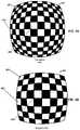
- FIG. 2Aexpresses the variance in solid angle for each square of a planar checkerboard perpendicular to the direction of view, in the case that the checkerboard subtends an angle of 114 degrees. In other words, it expresses the inefficiency of conventional planar projective rendering to a 114 degree FOV display.
- FIG. 2Bexpresses the same information for a 90 degree FOV display. In such planar projective rendering, the projection compresses tiles 202 in the image 201 that are at the edges and tiles 203 at the corners into smaller solid angles compared to tiles 204 at the center.
- each tile in the image 201has the same number of pixels in screen space, there is an inefficiency factor of roughly 4 ⁇ for rendering the edge tiles 202 compared to the center tiles 204 .
- conventional rendering of the edge tiles 202involves roughly 4 times as much processing per unit solid angle than for the center tiles 204 .
- the inefficiency factoris roughly 8 ⁇ .
- the inefficiency factoris roughly 2.5 ⁇ .
- the inefficiencyis dependent on the size of the FOV. For example, for the 90 degree FOV display shown in FIG. 2B , the inefficiency factors are roughly 2 ⁇ for rendering the edge tiles 202 , roughly 3 ⁇ for rendering the corner tiles 203 , and roughly 1.7 ⁇ overall for rendering the image 201 .
- FIG. 2CAnother way of looking at this situation is shown in FIG. 2C , in which the screen 102 has been divided into rectangles of approximately equal “importance” in terms of pixels per unit solid angle subtended. Each rectangle makes roughly the same contribution to the final image as seen through the display.
- the planar projectiondistorts the importance of edge rectangles 202 and corner rectangles 203 .
- the corner rectangles 203might make less of a contribution to the center rectangles due to the display optics, which may choose to make the visual density of pixels (as expressed as pixels per solid angle) higher towards the center of the display.
- an image 210 for a wide FOV displayit would be advantageous for an image 210 for a wide FOV display to have pixel densities that are smaller at edge regions 212 , 214 , 216 , 218 than at center regions 215 and smaller at corner regions 211 , 213 , 217 and 219 than at the edge regions 212 , 214 , 216 , 218 as shown in FIG. 2D . It would also be advantageous to render a conventional graphical image on the screen of a wide FOV display in a way that gets the same effect as varying the pixel densities across the screen without having to significantly modify the underlying graphical image data or data format or the processing of the data.
- part of the graphics pipelineuses metadata that specifies the number of active color samples per pixel in different regions of the screen.
- the metadatais associated with the screen, not the image.
- the image datais not changed, but in the graphics pipeline pixel shader execution is done only over the active color samples. For example, in the image data there may be four color samples per pixel.
- the metadatamay specify the active count to be four, in which case, the pixel shader is invoked for all four color samples. In a 3 ⁇ 4 resolution region, the active count may be three, in which case, the pixel shader is invoked for three of the four color samples (e.g., the first 3).
- the active countIn a 1 ⁇ 2 resolution region, the active count would be two and the pixel shader would be invoked for two of the color samples. In a 1 ⁇ 4 resolution region, the active count would be one and the pixel shader would be invoked for only one of the four color samples.
- FIG. 3Aillustrates a block diagram of a computer system 300 that may be used to implement graphics processing according to aspects of the present disclosure.
- the system 300may be an embedded system, mobile phone, personal computer, tablet computer, portable game device, workstation, game console, and the like.
- the system 300generally may include a central processor unit (CPU) 302 , a graphics processor unit (GPU) 304 , and a memory 308 that is accessible to both the CPU and GPU.
- the CPU 302 and GPU 304may each include one or more processor cores, e.g., a single core, two cores, four cores, eight cores, or more.
- the memory 308may be in the form of an integrated circuit that provides addressable memory, e.g., RAM, DRAM, and the like.
- the memory 308may include graphics memory 328 that may store graphics resources and temporarily store graphics buffers 305 of data for a graphics rendering pipeline.
- the graphics buffers 305may include, e.g., vertex buffers for storing vertex parameter values, index buffers for holding vertex indices, depth buffers (e.g., Z-buffers) for storing depth values of graphics content, stencil buffers, frame buffers for storing completed frames to be sent to a display, and other buffers.
- vertex buffersfor storing vertex parameter values
- index buffersfor holding vertex indices
- depth bufferse.g., Z-buffers
- the graphics memory 328is shown as part of the main memory.
- the graphics memorycould be a separate component, possibly integrated into the GPU 304 .
- the CPU 302 and GPU 304may access the memory 308 using a data bus 309 . In some cases, it may be useful for the system 300 to include two or more different buses.
- the memory 308may contain data that can be accessed by the CPU 302 and GPU 304 .
- the GPU 304may include a plurality of compute units configured to perform graphics processing tasks in parallel. Each compute unit may include its own dedicated local memory store, such as a local data share.
- the CPUmay be configured to execute CPU code 303 C , which may include an application that utilizes graphics, a compiler and a graphics API.
- the graphics APIcan be configured to issue draw commands to programs implemented by the GPU.
- the CPU code 303 Cmay also implement physics simulations and other functions.
- the GPU 304may be configured to operate as discussed above.
- the GPUmay execute GPU code 303 G , which may implement shaders, such as compute shaders CS, vertex shaders VS, and pixel shaders PS, as discussed above.
- the systemmay include one or more buffers 305 , which may include a frame buffer FB.
- the GPU code 303 Gmay also optionally implement other types of shaders (not shown), such as pixel shaders or geometry shaders.
- Each compute unitmay include its own dedicated local memory store, such as a local data share.
- the GPU 304may include a texture unit 306 configured to perform certain operations for applying textures to primitives as part of a graphics pipeline.
- the CPU code 303 c and GPU code 303 g and other elements of the system 300are configured so that a rasterization stage of the graphics pipeline receives metadata MD specifying an active sample configuration for a particular region of the display device 316 among a plurality of regions of the display device.
- the rasterization stagereceives pixel data for one or more pixels in the particular region.
- the pixel dataspecifies the same sample count (number of color samples for each pixel) over the entire surface.
- the active sample countis less than or equal to the color sample count and the color sample count is two or more.
- the rasterization stageinvokes a pixel shader PS only for active samples.
- the metadata MDspecifies different active sample configurations for regions that are to have different pixel sample resolutions (number of pixel samples per unit area of the display). In this way pixel sample resolution can vary for different regions of the display device 316 and the graphics processing load can be reduced for low-resolution regions of the display simply by reducing the active sample count for these regions relative to high resolution regions.
- the metadata MDincludes a mask of active samples for each region.
- the GPU 304performs a logical AND between the mask a samples covered by a primitive to determine the active samples for the primitive for which the pixel shader is to be invoked.
- the metadata MDspecifies an active sample count for a particular region of the display device 316 among a plurality of regions of the display device.
- the active sample countis less than or equal to the color sample count and the color sample count is two or more.
- the rasterization stageinvokes a pixel shader PS only for a number of the color samples for the pixel equal to the active sample count, typically sequential color samples starting with the first in some consistently defined sample order.
- the CPU code 303 c , GPU code 303 g , and texture unit 306may be further configured to implement certain texture mapping operations to implement modifications to texture mapping operations in conjunction with screen location dependent variable pixel resolution.
- a pixel shader PS and the texture unit 306can be configured to generate one or more texture coordinates UV per pixel location XY for a primitive to provide a coordinate set for one or more texture mapping operations, calculate gradient values Gr from the texture coordinates UV (possibly including corrections to account for differing sample density over the screen) and determine a level of detail (LOD) for a texture to apply to the primitive.
- LODlevel of detail
- certain components of the GPUe.g., certain types of shaders or the texture unit 306 , may be implemented as special purpose hardware, such as an application-specific integrated circuit (ASIC), Field Programmable Gate Array (FPGA), or a system on chip (SoC or SOC).
- ASICapplication-specific integrated circuit
- FPGAField Programmable Gate Array
- SoCsystem on chip
- an application-specific integrated circuitis an integrated circuit customized for a particular use, rather than intended for general-purpose use.
- a Field Programmable Gate Arrayis an integrated circuit designed to be configured by a customer or a designer after manufacturing—hence “field-programmable”.
- the FPGA configurationis generally specified using a hardware description language (HDL), similar to that used for an ASIC.
- HDLhardware description language
- SoCsystem on a chip or system on chip
- SOCsystem on chip
- ICintegrated circuit
- a typical SoCincludes the following hardware components:
- DMA controllersroute data directly between external interfaces and memory, bypassing the processor core and thereby increasing the data throughput of the SoC.
- a typical SoCincludes both the hardware components described above, and executable instructions (e.g., software or firmware) that controls the processor core(s), peripherals and interfaces.
- executable instructionse.g., software or firmware
- some or all of the functions of the shaders or the texture unit 306may alternatively be implemented by appropriately configured software instructions executed by a software programmable general purpose computer processor. Such instructions may be embodied in a computer-readable medium, e.g., memory 308 or storage device 315 .
- the system 300may also include well-known support functions 310 , which may communicate with other components of the system, e.g., via the bus 309 .
- Such support functionsmay include, but are not limited to, input/output (I/O) elements 311 , power supplies (P/S) 312 , a clock (CLK) 313 and cache 314 .
- the GPU 304may include its own GPU cache 314 G , and the GPU may be configured so that programs running on the GPU 304 can read-through or write-though the GPU cache 314 G .
- the system 300may include the display device 316 to present rendered graphics 317 to a user.
- the display device 316is a separate component that works in conjunction with the system 300 .
- the display device 316may be in the form of a flat panel display, head mounted display (HMD), cathode ray tube (CRT) screen, projector, or other device that can display visible text, numerals, graphical symbols or images.
- the display 316is a large field of view (FOV) device having a curved screen.
- the display device 316displays rendered graphic images 317 processed in accordance with various techniques described herein.
- the system 300may optionally include a mass storage device 315 such as a disk drive, CD-ROM drive, flash memory, tape drive, or the like to store programs and/or data.
- the system 300may also optionally include a user interface unit 318 to facilitate interaction between the system 300 and a user.
- the user interface 318may include a keyboard, mouse, joystick, light pen, game controller, or other device that may be used in conjunction with a graphical user interface (GUI).
- GUIgraphical user interface
- the system 300may also include a network interface 320 to enable the device to communicate with other devices over a network 322 .
- the network 322may be, e.g., a local area network (LAN), a wide area network such as the internet, a personal area network, such as a Bluetooth network or other type of network.
- LANlocal area network
- a wide area networksuch as the internet
- a personal area networksuch as a Bluetooth network or other type of network.
- the system 300is configured to implement portions of a graphics rendering pipeline.
- FIG. 3Billustrates an example of a graphics rendering pipeline 330 in accordance with aspects of the present disclosure.
- the rendering pipeline 330may be configured to render graphics as images that depict a scene having a two-dimensional or preferably three-dimensional geometry in virtual space (sometime referred to herein as “world space”).
- the early stages of the pipelinemay include operations performed in virtual space before the scene is rasterized and converted to screen space as a set of discrete picture elements suitable for output on the display device 316 .
- various resources contained in the graphics memory 328may be utilized at the pipeline stages and inputs and outputs to the stages may be temporarily stored in buffers contained in the graphics memory before the final values of the images are determined.
- the rendering pipelinemay operate on input data 332 , which may include one or more virtual objects defined by a set of vertices that are set up in virtual space and have geometry that is defined with respect to coordinates in the scene.
- the early stages of the pipelinemay include what is broadly categorized as a vertex processing stage 334 in FIG. 3B , and this may include various computations to process the vertices of the objects in virtual space.
- Thismay include vertex shading computations 336 , which may manipulate various parameter values of the vertices in the scene, such as position values (e.g., X-Y coordinate and Z-depth values), color values, lighting values, texture coordinates, and the like.
- the vertex shading computations 336are performed by one or more programmable vertex shaders.
- the vertex processing stagemay optionally include additional vertex processing computations, such as tessellation and geometry shader computations 338 which may be optionally used to generate new vertices and new geometries in virtual space.
- additional vertex processing computationssuch as tessellation and geometry shader computations 338 which may be optionally used to generate new vertices and new geometries in virtual space.
- the pipeline 330may then proceed to rasterization processing stages 340 associated with converting the scene geometry into screen space and a set of discrete picture elements, i.e., pixels.
- the virtual space geometrymay be transformed to screen space geometry through operations that may essentially compute the projection of the objects and vertices from virtual space to the viewing window (or “viewport”) of the scene.
- the verticesmay define a set of primitives.
- the rasterization processing stage 340 depicted in FIG. 3Bmay include primitive assembly operations 342 , which may set up the primitives defined by each set of vertices in the scene.
- Each vertexmay be defined by an index, and each primitive may be defined with respect to these vertex indices, which may be stored in index buffers in the graphics memory 328 .
- the primitivesmay preferably include at least triangles defined by three vertices each, but may also include point primitives line primitives, and other polygonal shapes.
- certain primitivesmay optionally be culled. For example, those primitives whose indices indicate a certain winding order may be considered to be back-facing and may be culled from the scene.
- the rasterization processing stagesmay include scan conversion operations 344 , which may sample the primitives at each pixel and generate fragments (sometimes referred to as pixels) from the primitives for further processing when the samples are covered by the primitive.
- scan conversion operations 344may sample the primitives at each pixel and generate fragments (sometimes referred to as pixels) from the primitives for further processing when the samples are covered by the primitive.
- multiple samples for each pixelare taken within the primitives during the scan conversion operations 344 , which may be used for anti-aliasing purposes.
- different pixelsmay be sampled differently. For example, some edge pixels may contain a lower sampling density than center pixels to optimize certain aspects of the rendering for certain types of display device 316 , such as head mounted displays (HMDs).
- HMDshead mounted displays
- the fragments (or “pixels”) generated from the primitives during scan conversion 344may have parameter values that may be interpolated to the locations of the pixels from the vertex parameter values 339 of the vertices of the primitive that created them.
- the rasterization stage 340may include parameter interpolation operations 346 stage to compute these interpolated fragment parameter values 349 , which may be used as inputs for further processing at the later stages of the pipeline.
- a coarse rasterization 343can be done to find all the predefined screen subsections (sometimes referred to herein as coarse rasterization tiles) that the primitive overlaps.
- sub-section dependent metadata MDe.g., an active sample count or other parameters, are received that allow the effective resolution to be modified for that subsection.
- Scan conversion 344 and subsequent processing stagesgenerate the final pixel values by performing pixel processing only on the specified number of active samples for the relevant subsection or subsections.
- the graphics pipeline 330may include further pixel processing operations, indicated generally at 350 in FIG. 3B , to further manipulate the interpolated parameter values 349 and perform further operations determining how the fragments contribute to the final pixel values for display 316 .
- Some of these pixel processing tasksmay include pixel shading computations 352 that may be used to further manipulate the interpolated parameter values 349 of the fragments.
- the pixel shading computationsmay be performed by a programmable pixel shader, and pixel shader invocations 348 may be initiated based on the sampling of the primitives during the rasterization processing stages 340 .
- the pixel shader invocations 348may also be initiated based on the metadata MD specifying the active sample count for each pixel in the particular region of the display device 316 in which a primitive is to be rendered. For each pixel in the particular region, pixel shader invocations 348 occur only for a number of the color samples for the pixel equal to the active sample count.
- FIG. 4Aillustrates an example of how the metadata MD could be configured to specify different active color samples for different regions 401 of the display screen 316 .
- each regionmay correspond to a fixed size portion of the display.
- each regionmay correspond to a variable size portion of the display.
- the metadata MDcan define each region 401 by ranges of pixels in the vertical and horizontal directions.
- the metadata MDcan define each region by coarse rasterization tiles of some size, e.g. 32 pixels ⁇ 32 pixels.
- the metadata associated with a particular regionincludes information specifying the active color sample count for that region.
- the metadatamay be stored in the form of a table in the memory 308 and/or graphics memory 328 .
- each pixel 403 of each region 401 of the display screen 316can be defined to have 8 depth samples and 4 color samples.
- the metadata for any particular regioncan specify an active color sample count of 1, 2, 3, or 4 for that region, depending on the desired resolution for that region.
- central regions of the screen 316are desired to have full resolution, so the metadata MD specifies an active sample count of 4 for those regions.
- the pixel shader invocations 348are unrolled as a default and depth samples are always written. If the invocations are always unrolled, the pixel shading computations 352 super-sample the pixels by virtue of being invoked for each active color sample, as opposed to multi-sampling them.
- the metadata MDspecifies 4 color samples per pixel for a central region 401 C and 2 color samples per pixel in an edge region 401 E it equates to 2 ⁇ higher resolution in the horizontal and vertical directions in the central region 401 C compared to the edge region 401 E .
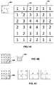
- FIG. 4Billustrates an example of a single sample per pixel image in which a 2-pixel by 2-pixel quad 406 represents 4 color samples that fully describe four pixels. Depth samples are not differentiated from color samples at this point in the example. For the triangle 405 , 3 of the 4 pixel-locations are covered by the triangle, so this one quad is passed to the pixel-shader PS for pixel shading computations 352 as a single fragment with 3 covered samples. The pixel shader PS shades 4 color samples and stores 3 of them in the frame-buffer FB.
- FIG. 4Cby contrast there are four color samples per pixel, so the 16 samples shown only correspond to 2 ⁇ 2 pixels, while in the example in FIG. 4B it was 4 ⁇ 4 pixels.
- This diagramshows the three fragments created when the active pixels are unrolled so that pixel shader invocation occurs on each covered sample, each contains one covered sample.
- the active sample countcan be varied by selectively disabling samples specified by the metadata MD. For example, if the upper right and lower left samples in each pixel are rendered inactive, only the one active sample location is covered and therefore only the middle of the three fragments depicted in FIG. 4C would be passed to the pixel-shader PS.
- the metadatais fixed for the optics and FOV of the display 316 .
- FIG. 4Dillustrates an example of how the metadata MD could be configured to specify different active pixel samples (or active color samples) for different subsections 401 of the display screen 316 .
- central subsections of the screen 316are desired to have full resolution, and subsections further from the center have progressively lower resolution.
- each pixel 403 of each region 401 of the display screen 316can be defined to have a fixed number of depth and color samples, e.g., 8 depth samples and 4 color samples.
- the metadata for any particular regioncan specify an active color sample count of 1, 2, 3, or 4 for that region, depending on the desired resolution for that region.
- the metadatacould vary to implement foveal rendering for eye tracking.
- the system 300includes hardware for tracking a user's gaze, i.e., where a user's eye is pointing, and relating this information to a corresponding screen location that the user is looking at.
- One example of such hardwarecould include a digital camera in a known location with respect to the screen of the display device 316 and pointed in the general direction of a user. The digital camera could be part of the user interface 318 or a separate component.
- the CPU code 303 Ccould include image analysis software that analyzes images from the camera to determine (a) if the user is in the image; (b) if the user is facing the camera; (c) if the user is facing the screen; (d) if the user's eyes are visible; (e) the orientation of the pupils of the user's eyes relative to the user's head; and (f) the orientation of the user's head relative to the camera. From the known position and orientation of the camera with respect to the screen, the orientation of the pupils of the user's eyes relative to the user's head and the orientation of the user's head relative to the camera the image analysis software could determine whether the user is looking at the screen and, if so, screen space coordinates for the portion 401 of the screen the user is looking at.
- the CPU code 303 ccould then pass these screen coordinates to the GPU code 303 G , which could determine the subsection or subsections containing the portion 401 .
- the GPU codecould then modify the metadata MD accordingly so that the pixel resolution is highest in the subsection or subsections containing the portion 401 and progressively lower in subsections further away from the portion 401 , as shown in FIG. 4E .
- the pixel shading computations 352may output values to one or more buffers 305 in graphics memory 328 , sometimes referred to as render targets, or if multiple, as multiple render targets (MRTs).
- MRTsallow pixel shaders to optionally output to more than one render target, each with the same screen dimensions but potentially with a different pixel format.
- Render target format limitationsoften mean that any one render target can only accept up to four independent output values (channels) and that the formats of those four channels are tightly tied to each other.
- MRTsallow a single pixel shader to output many more values in a mix of different formats.
- render targetsare “texture-like”, in that they store values per screen space pixel, but, for various performance reasons, render target formats are becoming more specialized in recent hardware generations, sometimes (but not always) requiring what is called a “resolve” to reformat the data before it is compatible with being read in by the texture units.
- the pixel processing 350may generally culminate in render output operations 356 , which may include what are commonly known as raster operations (ROP). Rasterization Operations (ROP) is simply run multiple times per pixel, once for each render target among the multiple render targets (MRTs).
- the final pixel values 359may be determined in a frame buffer, which may optionally include merging fragments, applying stencils, depth tests, and certain per sample processing tasks.
- the final pixel values 359include the collected output to all active render targets (MRTs).
- the GPU 304uses the final pixel values 359 to make up a finished frame 360 , which may optionally be displayed on the pixels of the display device 316 in real-time.
- the output operations 350may also include texture mapping operations 354 , which may be performed to some extent by one or more shaders (e.g., pixel shaders PS compute shaders CS, vertex shaders VS or other types of shaders) and to some extent by the texture units 306 .
- the shader computations 352include calculating texture coordinates UV from screen space coordinates XY, and sending the texture coordinates to the Texture Operations 354 , and receiving texture data TX.
- the texture coordinates UVcould be calculated from the screen space coordinates XY in an arbitrary fashion, but typically are calculated from interpolated input values or sometimes from the results of previous texture operations.
- Gradients Grare often directly calculated from quads of texture coordinates by the texture units 306 (Texture Operations hardware units), but can optionally be calculated explicitly by the pixel shader computations 352 and passed to the texture operations 354 rather than relying on the texture units 306 to perform the default calculation.
- the texture operations 356generally include the following stages, which can be performed by some combination of a pixel shader PS and a texture unit 306 .
- gradient values Grare calculated from the texture coordinates UV (potentially with corrections for non-orthonormality of the sample locations) and used to determine a level of detail (LOD) for a texture to apply to the primitive.
- LODlevel of detail
- Additional aspects of the present disclosureinclude a graphics processing method, comprising: receiving metadata specifying an active sample configuration for a particular region of the display device among a plurality of regions of the display device; receiving pixel data for one or more pixels in the particular region, wherein the pixel data specifies the same number of color samples for each pixel; and for each pixel in the particular region, invoking a pixel shader only for color samples specified to be active samples by the active sample configuration.
- An additional aspect of the present disclosureincludes a graphics processing method in which different regions of a screen of a display device have different pixel resolution.
- Another additional aspectis a computer-readable medium having computer executable instructions embodied therein that, when executed, implement one or both of the foregoing methods.
- a further aspectis an electromagnetic or other signal carrying computer-readable instructions for performing one or both of the foregoing methods.
- An additional further aspectis a computer program product downloadable from a communication network and/or stored on a computer-readable and/or microprocessor-executable medium, characterized in that it comprises program code instructions for implementing one or both of the foregoing methods.
- Another additional further aspectis a graphics processing system configured to implement one or both of the foregoing methods.
Landscapes
- Engineering & Computer Science (AREA)
- Physics & Mathematics (AREA)
- Theoretical Computer Science (AREA)
- General Physics & Mathematics (AREA)
- Computer Graphics (AREA)
- Computing Systems (AREA)
- Geometry (AREA)
- Image Generation (AREA)
Abstract
Description
- One or more processor cores (e.g., microcontroller, microprocessor or digital signal processor (DSP) cores.
- Memory blocks, e.g., read only memory (ROM), random access memory (RAM), electrically erasable programmable read-only memory (EEPROM) and flash memory.
- Timing sources, such as oscillators or phase-locked loops.
- Peripherals, such as counter-timers, real-time timers, or power-on reset generators.
- External interfaces, e.g., industry standards such as universal serial bus (USB), FireWire, Ethernet, universal asynchronous receiver/transmitter (USART), serial peripheral interface (SPI) bus.
- Analog interfaces including analog to digital converters (ADCs) and digital to analog converters (DACs).
- Voltage regulators and power management circuits.
Claims (33)
Priority Applications (1)
| Application Number | Priority Date | Filing Date | Title |
|---|---|---|---|
| US16/807,044US11302054B2 (en) | 2014-04-05 | 2020-03-02 | Varying effective resolution by screen location by changing active color sample count within multiple render targets |
Applications Claiming Priority (3)
| Application Number | Priority Date | Filing Date | Title |
|---|---|---|---|
| US14/246,061US10068311B2 (en) | 2014-04-05 | 2014-04-05 | Varying effective resolution by screen location by changing active color sample count within multiple render targets |
| US16/119,274US10614549B2 (en) | 2014-04-05 | 2018-08-31 | Varying effective resolution by screen location by changing active color sample count within multiple render targets |
| US16/807,044US11302054B2 (en) | 2014-04-05 | 2020-03-02 | Varying effective resolution by screen location by changing active color sample count within multiple render targets |
Related Parent Applications (1)
| Application Number | Title | Priority Date | Filing Date |
|---|---|---|---|
| US16/119,274ContinuationUS10614549B2 (en) | 2014-04-05 | 2018-08-31 | Varying effective resolution by screen location by changing active color sample count within multiple render targets |
Publications (3)
| Publication Number | Publication Date |
|---|---|
| US20210272348A1 US20210272348A1 (en) | 2021-09-02 |
| US20220068004A9 US20220068004A9 (en) | 2022-03-03 |
| US11302054B2true US11302054B2 (en) | 2022-04-12 |
Family
ID=80357118
Family Applications (1)
| Application Number | Title | Priority Date | Filing Date |
|---|---|---|---|
| US16/807,044Active2034-04-15US11302054B2 (en) | 2014-04-05 | 2020-03-02 | Varying effective resolution by screen location by changing active color sample count within multiple render targets |
Country Status (1)
| Country | Link |
|---|---|
| US (1) | US11302054B2 (en) |
Families Citing this family (3)
| Publication number | Priority date | Publication date | Assignee | Title |
|---|---|---|---|---|
| CN110324601A (en)* | 2018-03-27 | 2019-10-11 | 京东方科技集团股份有限公司 | Rendering method, computer product and display device |
| CN114065336B (en)* | 2021-09-28 | 2022-07-22 | 广州优比建筑咨询有限公司 | Revit-based high formwork region inspection method, device, medium and equipment |
| GB2615362B (en)* | 2022-02-08 | 2024-03-13 | Sony Interactive Entertainment Inc | Image processing system and method |
Citations (118)
| Publication number | Priority date | Publication date | Assignee | Title |
|---|---|---|---|---|
| US4513317A (en) | 1982-09-28 | 1985-04-23 | The United States Of America As Represented By The Administrator Of The National Aeronautics And Space Administration | Retinally stabilized differential resolution television display |
| US5130794A (en) | 1990-03-29 | 1992-07-14 | Ritchey Kurtis J | Panoramic display system |
| US5224208A (en) | 1990-03-16 | 1993-06-29 | Hewlett-Packard Company | Gradient calculation for texture mapping |
| US5422653A (en) | 1993-01-07 | 1995-06-06 | Maguire, Jr.; Francis J. | Passive virtual reality |
| US5602391A (en) | 1995-02-23 | 1997-02-11 | Hughes Electronics | Quincunx sampling grid for staring array |
| US5777913A (en) | 1995-12-27 | 1998-07-07 | Ericsson Inc. | Resolution enhancement of fixed point digital filters |
| USH1812H (en) | 1997-10-24 | 1999-11-02 | Sun Microsystems, Inc. | Method for encoding bounding boxes of drawing primitives to be rendered for multi-resolution supersampled frame buffers |
| JP2000155850A (en) | 1998-11-20 | 2000-06-06 | Sony Corp | Texture mapping device and rendering device equipped with the same device and information processor |
| US6313838B1 (en) | 1998-02-17 | 2001-11-06 | Sun Microsystems, Inc. | Estimating graphics system performance for polygons |
| US20010055025A1 (en) | 1998-02-17 | 2001-12-27 | Sun Microsystems, Inc. | Graphics system configured to filter samples using a variable support filter |
| JP2002503855A (en) | 1998-02-17 | 2002-02-05 | サン・マイクロシステムズ・インコーポレーテッド | Graphics system with variable resolution supersampling |
| US20020057279A1 (en) | 1999-05-20 | 2002-05-16 | Compaq Computer Corporation | System and method for displaying images using foveal video |
| US6417861B1 (en) | 1999-02-17 | 2002-07-09 | Sun Microsystems, Inc. | Graphics system with programmable sample positions |
| US20020097241A1 (en) | 2000-08-18 | 2002-07-25 | Mccormack Joel James | System and method for producing an antialiased image using a merge buffer |
| JP2002260003A (en) | 2001-03-02 | 2002-09-13 | Hitachi Ltd | Video display device |
| US6469700B1 (en) | 1998-06-24 | 2002-10-22 | Micron Technology, Inc. | Per pixel MIP mapping and trilinear filtering using scanline gradients for selecting appropriate texture maps |
| JP2002537614A (en) | 1999-02-17 | 2002-11-05 | サン マイクロシステムズ,インコーポレイティッド | Graphics system configured to perform parallel sample pixel calculations |
| US20030011618A1 (en) | 1998-02-17 | 2003-01-16 | Sun Microsystems, Inc. | Graphics system with a programmable sample position memory |
| US20030086603A1 (en) | 2001-09-07 | 2003-05-08 | Distortion Graphics, Inc. | System and method for transforming graphical images |
| US20030112238A1 (en) | 2001-10-10 | 2003-06-19 | Cerny Mark Evan | System and method for environment mapping |
| US20030112240A1 (en) | 2001-10-10 | 2003-06-19 | Cerny Mark Evan | System and method for point pushing to render polygons in environments with changing levels of detail |
| US20030122833A1 (en) | 2001-12-31 | 2003-07-03 | Doyle Peter L. | Efficient graphics state management for zone rendering |
| US20030234784A1 (en) | 2002-06-21 | 2003-12-25 | Radek Grzeszczuk | Accelerated visualization of surface light fields |
| US20040036692A1 (en) | 2002-08-23 | 2004-02-26 | Byron Alcorn | System and method for calculating a texture-mapping gradient |
| US6731298B1 (en) | 2000-10-02 | 2004-05-04 | Nvidia Corporation | System, method and article of manufacture for z-texture mapping |
| US20040169663A1 (en) | 2003-03-01 | 2004-09-02 | The Boeing Company | Systems and methods for providing enhanced vision imaging |
| US6804066B1 (en) | 2001-05-23 | 2004-10-12 | University Of Central Florida | Compact lens assembly for the teleportal augmented reality system |
| US20040212619A1 (en) | 2003-04-28 | 2004-10-28 | Kabushiki Kaisha Toshiba | Image rendering device and image rendering method |
| US20040227703A1 (en) | 2003-05-13 | 2004-11-18 | Mcnc Research And Development Institute | Visual display with increased field of view |
| US20050017983A1 (en) | 2003-02-20 | 2005-01-27 | Liao Qun Feng | Approximation of level of detail calculation in cubic mapping without attribute delta function |
| US6906723B2 (en) | 2001-03-29 | 2005-06-14 | International Business Machines Corporation | Generating partials for perspective corrected texture coordinates in a four pixel texture pipeline |
| US20050190183A1 (en) | 2003-07-07 | 2005-09-01 | Stmicroelectronics S.R.L. | Geometric processing stage for a pipelined graphic engine, corresponding method and computer program product therefor |
| US20050225670A1 (en) | 2004-04-02 | 2005-10-13 | Wexler Daniel E | Video processing, such as for hidden surface reduction or removal |
| US6967663B1 (en) | 2003-09-08 | 2005-11-22 | Nvidia Corporation | Antialiasing using hybrid supersampling-multisampling |
| US20060077209A1 (en) | 2004-10-07 | 2006-04-13 | Bastos Rui M | Pixel center position displacement |
| JP2006293627A (en) | 2005-04-08 | 2006-10-26 | Toshiba Corp | Drawing method and drawing apparatus |
| US20060256112A1 (en) | 2005-05-10 | 2006-11-16 | Sony Computer Entertainment Inc. | Statistical rendering acceleration |
| US20060277520A1 (en) | 2001-09-11 | 2006-12-07 | The Regents Of The University Of California | Method of locating areas in an image such as a photo mask layout that are sensitive to residual processing effects |
| US20070018988A1 (en) | 2005-07-20 | 2007-01-25 | Michael Guthe | Method and applications for rasterization of non-simple polygons and curved boundary representations |
| US20070165035A1 (en) | 1998-08-20 | 2007-07-19 | Apple Computer, Inc. | Deferred shading graphics pipeline processor having advanced features |
| US20070183649A1 (en) | 2004-03-15 | 2007-08-09 | Koninklijke Philips Electronic, N.V. | Image visualization |
| US7336277B1 (en) | 2003-04-17 | 2008-02-26 | Nvidia Corporation | Per-pixel output luminosity compensation |
| US7339594B1 (en) | 2005-03-01 | 2008-03-04 | Nvidia Corporation | Optimized anisotropic texture sampling |
| US20080062164A1 (en) | 2006-08-11 | 2008-03-13 | Bassi Zorawar | System and method for automated calibration and correction of display geometry and color |
| US20080106489A1 (en) | 2006-11-02 | 2008-05-08 | Brown Lawrence G | Systems and methods for a head-mounted display |
| US20080113792A1 (en) | 2006-11-15 | 2008-05-15 | Nintendo Co., Ltd. | Storage medium storing game program and game apparatus |
| US20080129748A1 (en) | 2003-11-19 | 2008-06-05 | Reuven Bakalash | Parallel graphics rendering system supporting parallelized operation of multiple graphics processing pipelines within diverse system architectures |
| US7426724B2 (en) | 2004-07-02 | 2008-09-16 | Nvidia Corporation | Optimized chaining of vertex and fragment programs |
| JP2008233765A (en) | 2007-03-23 | 2008-10-02 | Toshiba Corp | Image display device and image display method |
| US20090002380A1 (en) | 2006-11-10 | 2009-01-01 | Sony Computer Entertainment Inc. | Graphics Processing Apparatus, Graphics Library Module And Graphics Processing Method |
| US20090033659A1 (en) | 2007-07-31 | 2009-02-05 | Lake Adam T | Real-time luminosity dependent subdivision |
| US7511717B1 (en) | 2005-07-15 | 2009-03-31 | Nvidia Corporation | Antialiasing using hybrid supersampling-multisampling |
| JP2009520307A (en) | 2005-12-19 | 2009-05-21 | エヌヴィディア コーポレイション | Graphics processor parallel array architecture |
| JP2009116550A (en) | 2007-11-05 | 2009-05-28 | Fujitsu Microelectronics Ltd | Drawing processing apparatus, drawing processing method, and drawing processing program |
| US20090141033A1 (en) | 2007-11-30 | 2009-06-04 | Qualcomm Incorporated | System and method for using a secondary processor in a graphics system |
| TW201001329A (en) | 2008-03-20 | 2010-01-01 | Qualcomm Inc | Multi-stage tessellation for graphics rendering |
| US20100002000A1 (en) | 2008-07-03 | 2010-01-07 | Everitt Cass W | Hybrid Multisample/Supersample Antialiasing |
| US20100007662A1 (en) | 2008-06-05 | 2010-01-14 | Arm Limited | Graphics processing systems |
| US20100104162A1 (en) | 2008-10-23 | 2010-04-29 | Immersion Corporation | Systems And Methods For Ultrasound Simulation Using Depth Peeling |
| US20100110102A1 (en) | 2008-10-24 | 2010-05-06 | Arm Limited | Methods of and apparatus for processing computer graphics |
| US20100156919A1 (en) | 2008-12-19 | 2010-06-24 | Xerox Corporation | Systems and methods for text-based personalization of images |
| US20100214294A1 (en) | 2009-02-20 | 2010-08-26 | Microsoft Corporation | Method for tessellation on graphics hardware |
| WO2010111258A1 (en) | 2009-03-24 | 2010-09-30 | Advanced Micro Devices, Inc. | Method and apparatus for angular invariant texture level of detail generation |
| US7876332B1 (en) | 2006-12-20 | 2011-01-25 | Nvidia Corporation | Shader that conditionally updates a framebuffer in a computer graphics system |
| US7907792B2 (en) | 2006-06-16 | 2011-03-15 | Hewlett-Packard Development Company, L.P. | Blend maps for rendering an image frame |
| US7916155B1 (en) | 2007-11-02 | 2011-03-29 | Nvidia Corporation | Complementary anti-aliasing sample patterns |
| JP2011066860A (en) | 2009-09-18 | 2011-03-31 | Loarant Corp | Panoramic image generation method and panoramic image generation program |
| US20110090242A1 (en) | 2009-10-20 | 2011-04-21 | Apple Inc. | System and method for demosaicing image data using weighted gradients |
| US20110090250A1 (en) | 2009-10-15 | 2011-04-21 | Molnar Steven E | Alpha-to-coverage using virtual samples |
| US20110134136A1 (en) | 2009-12-03 | 2011-06-09 | Larry Seiler | Computing Level of Detail for Anisotropic Filtering |
| US20110188744A1 (en) | 2010-02-04 | 2011-08-04 | Microsoft Corporation | High dynamic range image generation and rendering |
| US20110216069A1 (en) | 2010-03-08 | 2011-09-08 | Gary Keall | Method And System For Compressing Tile Lists Used For 3D Rendering |
| US8044956B1 (en) | 2007-08-03 | 2011-10-25 | Nvidia Corporation | Coverage adaptive multisampling |
| US8090383B1 (en) | 2004-02-17 | 2012-01-03 | Emigh Aaron T | Method and system for charging for a service based on time spent at a facility |
| US20120014576A1 (en) | 2009-12-11 | 2012-01-19 | Aperio Technologies, Inc. | Signal to Noise Ratio in Digital Pathology Image Analysis |
| US20120069021A1 (en) | 2010-09-20 | 2012-03-22 | Samsung Electronics Co., Ltd. | Apparatus and method of early pixel discarding in graphic processing unit |
| US8144156B1 (en) | 2003-12-31 | 2012-03-27 | Zii Labs Inc. Ltd. | Sequencer with async SIMD array |
| US20120092366A1 (en) | 2010-10-13 | 2012-04-19 | Qualcomm Incorporated | Systems and methods for dynamic procedural texture generation management |
| US8207975B1 (en) | 2006-05-08 | 2012-06-26 | Nvidia Corporation | Graphics rendering pipeline that supports early-Z and late-Z virtual machines |
| US8228328B1 (en) | 2006-11-03 | 2012-07-24 | Nvidia Corporation | Early Z testing for multiple render targets |
| US8233004B1 (en) | 2006-11-06 | 2012-07-31 | Nvidia Corporation | Color-compression using automatic reduction of multi-sampled pixels |
| US20120206452A1 (en) | 2010-10-15 | 2012-08-16 | Geisner Kevin A | Realistic occlusion for a head mounted augmented reality display |
| US8300059B2 (en) | 2006-02-03 | 2012-10-30 | Ati Technologies Ulc | Method and apparatus for selecting a mip map level based on a min-axis value for texture mapping |
| US20120293519A1 (en) | 2011-05-16 | 2012-11-22 | Qualcomm Incorporated | Rendering mode selection in graphics processing units |
| US20120293486A1 (en) | 2011-05-20 | 2012-11-22 | Canon Kabushiki Kaisha | Image processing apparatus and image processing method |
| US20130021358A1 (en) | 2011-07-22 | 2013-01-24 | Qualcomm Incorporated | Area-based rasterization techniques for a graphics processing system |
| JP2013033475A (en) | 2011-08-01 | 2013-02-14 | Harman Becker Automotive Systems Gmbh | Space error parameters for 3d buildings and terrain |
| US20130063440A1 (en) | 2011-09-14 | 2013-03-14 | Samsung Electronics Co., Ltd. | Graphics processing method and apparatus using post fragment shader |
| US20130093766A1 (en) | 2007-08-07 | 2013-04-18 | Nvidia Corporation | Interpolation of vertex attributes in a graphics processor |
| US20130114680A1 (en) | 2010-07-21 | 2013-05-09 | Dolby Laboratories Licensing Corporation | Systems and Methods for Multi-Layered Frame-Compatible Video Delivery |
| US20130120380A1 (en) | 2011-11-16 | 2013-05-16 | Qualcomm Incorporated | Tessellation in tile-based rendering |
| WO2013076994A1 (en) | 2011-11-24 | 2013-05-30 | パナソニック株式会社 | Head-mounted display device |
| US20130141445A1 (en) | 2011-12-05 | 2013-06-06 | Arm Limited | Methods of and apparatus for processing computer graphics |
| US20130265309A1 (en) | 2012-04-04 | 2013-10-10 | Qualcomm Incorporated | Patched shading in graphics processing |
| US8581929B1 (en) | 2012-06-05 | 2013-11-12 | Francis J. Maguire, Jr. | Display of light field image data using a spatial light modulator at a focal length corresponding to a selected focus depth |
| US20130300740A1 (en) | 2010-09-13 | 2013-11-14 | Alt Software (Us) Llc | System and Method for Displaying Data Having Spatial Coordinates |
| US20130342547A1 (en) | 2012-06-21 | 2013-12-26 | Eric LUM | Early sample evaluation during coarse rasterization |
| US20140049549A1 (en) | 2012-08-20 | 2014-02-20 | Maxim Lukyanov | Efficient placement of texture barrier instructions |
| US20140063016A1 (en) | 2012-07-31 | 2014-03-06 | John W. Howson | Unified rasterization and ray tracing rendering environments |
| US20140362081A1 (en) | 2013-06-10 | 2014-12-11 | Sony Computer Entertainment Inc. | Using compute shaders as front end for vertex shaders |
| US20140362101A1 (en) | 2013-06-10 | 2014-12-11 | Sony Computer Entertainment Inc. | Fragment shaders perform vertex shader computations |
| US20140362102A1 (en) | 2013-06-10 | 2014-12-11 | Sony Computer Entertainment Inc. | Graphics processing hardware for using compute shaders as front end for vertex shaders |
| US20140362100A1 (en) | 2013-06-10 | 2014-12-11 | Sony Computer Entertainment Inc. | Scheme for compressing vertex shader output parameters |
| US20150089367A1 (en) | 2013-09-24 | 2015-03-26 | Qnx Software Systems Limited | System and method for forwarding an application user interface |
| US9013499B2 (en) | 2007-07-19 | 2015-04-21 | Disney Enterprises, Inc. | Methods and apparatus for multiple texture map storage and filtering including irregular texture maps |
| US20150287230A1 (en) | 2014-04-05 | 2015-10-08 | Sony Computer Entertainment America Llc | Gradient adjustment for texture mapping for multiple render targets with resolution that varies by screen location |
| US20150287158A1 (en) | 2014-04-05 | 2015-10-08 | Sony Computer Entertainment America Llc | Method for efficient re-rendering objects to vary viewports and under varying rendering and rasterization parameters |
| US20150287167A1 (en) | 2014-04-05 | 2015-10-08 | Sony Computer Entertainment America Llc | Varying effective resolution by screen location in graphics processing by approximating projection of vertices onto curved viewport |
| US20150287166A1 (en) | 2014-04-05 | 2015-10-08 | Sony Computer Entertainment America Llc | Varying effective resolution by screen location by altering rasterization parameters |
| US20150287165A1 (en) | 2014-04-05 | 2015-10-08 | Sony Computer Entertainment Europe Limited | Varying effective resolution by screen location by changing active color sample count within multiple render targets |
| US20150287232A1 (en) | 2014-04-05 | 2015-10-08 | Sony Computer Entertainment America Llc | Gradient adjustment for texture mapping to non-orthonormal grid |
| US20160246323A1 (en) | 2015-02-20 | 2016-08-25 | Sony Computer Entertainment America Llc | Backward compatibility through use of spoof clock and fine grain frequency control |
| US20170031834A1 (en) | 2015-07-27 | 2017-02-02 | Sony Interactive Entertainment America Llc | Backward compatibility by restriction of hardware resources |
| US20170031732A1 (en) | 2015-07-27 | 2017-02-02 | Sony Computer Entertainment America Llc | Backward compatibility by algorithm matching, disabling features, or throttling performance |
| US20170123961A1 (en) | 2015-11-02 | 2017-05-04 | Sony Computer Entertainment America Llc | Backward compatibility testing of software in a mode that disrupts timing |
| US9710957B2 (en) | 2014-04-05 | 2017-07-18 | Sony Interactive Entertainment America Llc | Graphics processing enhancement by tracking object and/or primitive identifiers |
| US9865074B2 (en) | 2014-04-05 | 2018-01-09 | Sony Interactive Entertainment America Llc | Method for efficient construction of high resolution display buffers |
| US20200160584A1 (en) | 2014-04-05 | 2020-05-21 | Sony Interactive Entertainment LLC | Gradient adjustment for texture mapping to non-orthonormal grid |
- 2020
- 2020-03-02USUS16/807,044patent/US11302054B2/enactiveActive
Patent Citations (165)
| Publication number | Priority date | Publication date | Assignee | Title |
|---|---|---|---|---|
| US4513317A (en) | 1982-09-28 | 1985-04-23 | The United States Of America As Represented By The Administrator Of The National Aeronautics And Space Administration | Retinally stabilized differential resolution television display |
| US5224208A (en) | 1990-03-16 | 1993-06-29 | Hewlett-Packard Company | Gradient calculation for texture mapping |
| US5130794A (en) | 1990-03-29 | 1992-07-14 | Ritchey Kurtis J | Panoramic display system |
| US5422653A (en) | 1993-01-07 | 1995-06-06 | Maguire, Jr.; Francis J. | Passive virtual reality |
| US5602391A (en) | 1995-02-23 | 1997-02-11 | Hughes Electronics | Quincunx sampling grid for staring array |
| US5777913A (en) | 1995-12-27 | 1998-07-07 | Ericsson Inc. | Resolution enhancement of fixed point digital filters |
| USH1812H (en) | 1997-10-24 | 1999-11-02 | Sun Microsystems, Inc. | Method for encoding bounding boxes of drawing primitives to be rendered for multi-resolution supersampled frame buffers |
| US20030011618A1 (en) | 1998-02-17 | 2003-01-16 | Sun Microsystems, Inc. | Graphics system with a programmable sample position memory |
| US20010055025A1 (en) | 1998-02-17 | 2001-12-27 | Sun Microsystems, Inc. | Graphics system configured to filter samples using a variable support filter |
| JP2002503854A (en) | 1998-02-17 | 2002-02-05 | サン・マイクロシステムズ・インコーポレーテッド | Estimating graphics system performance for polygons |
| JP2002503855A (en) | 1998-02-17 | 2002-02-05 | サン・マイクロシステムズ・インコーポレーテッド | Graphics system with variable resolution supersampling |
| US6577312B2 (en) | 1998-02-17 | 2003-06-10 | Sun Microsystems, Inc. | Graphics system configured to filter samples using a variable support filter |
| US6424343B1 (en) | 1998-02-17 | 2002-07-23 | Sun Microsystems, Inc. | Graphics system with programmable real-time sample filtering |
| US6496187B1 (en) | 1998-02-17 | 2002-12-17 | Sun Microsystems, Inc. | Graphics system configured to perform parallel sample to pixel calculation |
| US6313838B1 (en) | 1998-02-17 | 2001-11-06 | Sun Microsystems, Inc. | Estimating graphics system performance for polygons |
| US6469700B1 (en) | 1998-06-24 | 2002-10-22 | Micron Technology, Inc. | Per pixel MIP mapping and trilinear filtering using scanline gradients for selecting appropriate texture maps |
| US20070165035A1 (en) | 1998-08-20 | 2007-07-19 | Apple Computer, Inc. | Deferred shading graphics pipeline processor having advanced features |
| US6476819B1 (en) | 1998-11-20 | 2002-11-05 | Sony Corporation | Apparatus and method for assigning shrinkage factor during texture mapping operations |
| JP2000155850A (en) | 1998-11-20 | 2000-06-06 | Sony Corp | Texture mapping device and rendering device equipped with the same device and information processor |
| JP2002537614A (en) | 1999-02-17 | 2002-11-05 | サン マイクロシステムズ,インコーポレイティッド | Graphics system configured to perform parallel sample pixel calculations |
| US6417861B1 (en) | 1999-02-17 | 2002-07-09 | Sun Microsystems, Inc. | Graphics system with programmable sample positions |
| US20020057279A1 (en) | 1999-05-20 | 2002-05-16 | Compaq Computer Corporation | System and method for displaying images using foveal video |
| US20020097241A1 (en) | 2000-08-18 | 2002-07-25 | Mccormack Joel James | System and method for producing an antialiased image using a merge buffer |
| US6731298B1 (en) | 2000-10-02 | 2004-05-04 | Nvidia Corporation | System, method and article of manufacture for z-texture mapping |
| JP2002260003A (en) | 2001-03-02 | 2002-09-13 | Hitachi Ltd | Video display device |
| US6906723B2 (en) | 2001-03-29 | 2005-06-14 | International Business Machines Corporation | Generating partials for perspective corrected texture coordinates in a four pixel texture pipeline |
| US6804066B1 (en) | 2001-05-23 | 2004-10-12 | University Of Central Florida | Compact lens assembly for the teleportal augmented reality system |
| US20030086603A1 (en) | 2001-09-07 | 2003-05-08 | Distortion Graphics, Inc. | System and method for transforming graphical images |
| US20060277520A1 (en) | 2001-09-11 | 2006-12-07 | The Regents Of The University Of California | Method of locating areas in an image such as a photo mask layout that are sensitive to residual processing effects |
| US20070002049A1 (en) | 2001-10-10 | 2007-01-04 | Cerny Mark E | System and method for generating additional polygons within the contours of a rendered object to control levels of detail |
| US20030112238A1 (en) | 2001-10-10 | 2003-06-19 | Cerny Mark Evan | System and method for environment mapping |
| US20030112240A1 (en) | 2001-10-10 | 2003-06-19 | Cerny Mark Evan | System and method for point pushing to render polygons in environments with changing levels of detail |
| US20100283783A1 (en) | 2001-10-10 | 2010-11-11 | Mark Evan Cerny | Environment Mapping |
| US8174527B2 (en) | 2001-10-10 | 2012-05-08 | Sony Computer Entertainment America Llc | Environment mapping |
| US8031192B2 (en) | 2001-10-10 | 2011-10-04 | Sony Computer Entertainment America Llc | System and method for generating additional polygons within the contours of a rendered object to control levels of detail |
| US7081893B2 (en) | 2001-10-10 | 2006-07-25 | Sony Computer Entertainment America Inc. | System and method for point pushing to render polygons in environments with changing levels of detail |
| US7046245B2 (en) | 2001-10-10 | 2006-05-16 | Sony Computer Entertainment America Inc. | System and method for environment mapping |
| US20060001674A1 (en) | 2001-10-10 | 2006-01-05 | Sony Computer Entertainment America Inc. | Environment mapping |
| US7786993B2 (en) | 2001-10-10 | 2010-08-31 | Sony Computer Entertainment America Llc | Environment mapping |
| US20030122833A1 (en) | 2001-12-31 | 2003-07-03 | Doyle Peter L. | Efficient graphics state management for zone rendering |
| US20030234784A1 (en) | 2002-06-21 | 2003-12-25 | Radek Grzeszczuk | Accelerated visualization of surface light fields |
| US20040036692A1 (en) | 2002-08-23 | 2004-02-26 | Byron Alcorn | System and method for calculating a texture-mapping gradient |
| US20050017983A1 (en) | 2003-02-20 | 2005-01-27 | Liao Qun Feng | Approximation of level of detail calculation in cubic mapping without attribute delta function |
| JP2004265413A (en) | 2003-03-01 | 2004-09-24 | Boeing Co:The | System and method for giving environmental image to view point of display |
| US20040169663A1 (en) | 2003-03-01 | 2004-09-02 | The Boeing Company | Systems and methods for providing enhanced vision imaging |
| US7336277B1 (en) | 2003-04-17 | 2008-02-26 | Nvidia Corporation | Per-pixel output luminosity compensation |
| US20040212619A1 (en) | 2003-04-28 | 2004-10-28 | Kabushiki Kaisha Toshiba | Image rendering device and image rendering method |
| US7161603B2 (en) | 2003-04-28 | 2007-01-09 | Kabushiki Kaisha Toshiba | Image rendering device and image rendering method |
| TWI250785B (en) | 2003-04-28 | 2006-03-01 | Toshiba Corp | Image rendering device and image rendering method |
| US20040227703A1 (en) | 2003-05-13 | 2004-11-18 | Mcnc Research And Development Institute | Visual display with increased field of view |
| US20050190183A1 (en) | 2003-07-07 | 2005-09-01 | Stmicroelectronics S.R.L. | Geometric processing stage for a pipelined graphic engine, corresponding method and computer program product therefor |
| US6967663B1 (en) | 2003-09-08 | 2005-11-22 | Nvidia Corporation | Antialiasing using hybrid supersampling-multisampling |
| US20080129748A1 (en) | 2003-11-19 | 2008-06-05 | Reuven Bakalash | Parallel graphics rendering system supporting parallelized operation of multiple graphics processing pipelines within diverse system architectures |
| US8144156B1 (en) | 2003-12-31 | 2012-03-27 | Zii Labs Inc. Ltd. | Sequencer with async SIMD array |
| US8090383B1 (en) | 2004-02-17 | 2012-01-03 | Emigh Aaron T | Method and system for charging for a service based on time spent at a facility |
| US20070183649A1 (en) | 2004-03-15 | 2007-08-09 | Koninklijke Philips Electronic, N.V. | Image visualization |
| US20050225670A1 (en) | 2004-04-02 | 2005-10-13 | Wexler Daniel E | Video processing, such as for hidden surface reduction or removal |
| US7426724B2 (en) | 2004-07-02 | 2008-09-16 | Nvidia Corporation | Optimized chaining of vertex and fragment programs |
| US20060077209A1 (en) | 2004-10-07 | 2006-04-13 | Bastos Rui M | Pixel center position displacement |
| US7339594B1 (en) | 2005-03-01 | 2008-03-04 | Nvidia Corporation | Optimized anisotropic texture sampling |
| US7355604B2 (en) | 2005-04-08 | 2008-04-08 | Kabushiki Kaisha Toshiba | Image rendering method and image rendering apparatus using anisotropic texture mapping |
| JP2006293627A (en) | 2005-04-08 | 2006-10-26 | Toshiba Corp | Drawing method and drawing apparatus |
| US20060256112A1 (en) | 2005-05-10 | 2006-11-16 | Sony Computer Entertainment Inc. | Statistical rendering acceleration |
| US7511717B1 (en) | 2005-07-15 | 2009-03-31 | Nvidia Corporation | Antialiasing using hybrid supersampling-multisampling |
| US20070018988A1 (en) | 2005-07-20 | 2007-01-25 | Michael Guthe | Method and applications for rasterization of non-simple polygons and curved boundary representations |
| JP2009520307A (en) | 2005-12-19 | 2009-05-21 | エヌヴィディア コーポレイション | Graphics processor parallel array architecture |
| US8730249B2 (en) | 2005-12-19 | 2014-05-20 | Nvidia Corporation | Parallel array architecture for a graphics processor |
| US8300059B2 (en) | 2006-02-03 | 2012-10-30 | Ati Technologies Ulc | Method and apparatus for selecting a mip map level based on a min-axis value for texture mapping |
| US8207975B1 (en) | 2006-05-08 | 2012-06-26 | Nvidia Corporation | Graphics rendering pipeline that supports early-Z and late-Z virtual machines |
| US7907792B2 (en) | 2006-06-16 | 2011-03-15 | Hewlett-Packard Development Company, L.P. | Blend maps for rendering an image frame |
| US20080062164A1 (en) | 2006-08-11 | 2008-03-13 | Bassi Zorawar | System and method for automated calibration and correction of display geometry and color |
| US20080106489A1 (en) | 2006-11-02 | 2008-05-08 | Brown Lawrence G | Systems and methods for a head-mounted display |
| US8228328B1 (en) | 2006-11-03 | 2012-07-24 | Nvidia Corporation | Early Z testing for multiple render targets |
| US8233004B1 (en) | 2006-11-06 | 2012-07-31 | Nvidia Corporation | Color-compression using automatic reduction of multi-sampled pixels |
| US8149242B2 (en) | 2006-11-10 | 2012-04-03 | Sony Computer Entertainment Inc. | Graphics processing apparatus, graphics library module and graphics processing method |
| US20090002380A1 (en) | 2006-11-10 | 2009-01-01 | Sony Computer Entertainment Inc. | Graphics Processing Apparatus, Graphics Library Module And Graphics Processing Method |
| US20080113792A1 (en) | 2006-11-15 | 2008-05-15 | Nintendo Co., Ltd. | Storage medium storing game program and game apparatus |
| US7876332B1 (en) | 2006-12-20 | 2011-01-25 | Nvidia Corporation | Shader that conditionally updates a framebuffer in a computer graphics system |
| JP2008233765A (en) | 2007-03-23 | 2008-10-02 | Toshiba Corp | Image display device and image display method |
| US9013499B2 (en) | 2007-07-19 | 2015-04-21 | Disney Enterprises, Inc. | Methods and apparatus for multiple texture map storage and filtering including irregular texture maps |
| US20090033659A1 (en) | 2007-07-31 | 2009-02-05 | Lake Adam T | Real-time luminosity dependent subdivision |
| TW200919376A (en) | 2007-07-31 | 2009-05-01 | Intel Corp | Real-time luminosity dependent subdivision |
| US8044956B1 (en) | 2007-08-03 | 2011-10-25 | Nvidia Corporation | Coverage adaptive multisampling |
| US20130093766A1 (en) | 2007-08-07 | 2013-04-18 | Nvidia Corporation | Interpolation of vertex attributes in a graphics processor |
| US7916155B1 (en) | 2007-11-02 | 2011-03-29 | Nvidia Corporation | Complementary anti-aliasing sample patterns |
| JP2009116550A (en) | 2007-11-05 | 2009-05-28 | Fujitsu Microelectronics Ltd | Drawing processing apparatus, drawing processing method, and drawing processing program |
| US20090141033A1 (en) | 2007-11-30 | 2009-06-04 | Qualcomm Incorporated | System and method for using a secondary processor in a graphics system |
| TW201001329A (en) | 2008-03-20 | 2010-01-01 | Qualcomm Inc | Multi-stage tessellation for graphics rendering |
| US8643644B2 (en) | 2008-03-20 | 2014-02-04 | Qualcomm Incorporated | Multi-stage tessellation for graphics rendering |
| US20100007662A1 (en) | 2008-06-05 | 2010-01-14 | Arm Limited | Graphics processing systems |
| US20100002000A1 (en) | 2008-07-03 | 2010-01-07 | Everitt Cass W | Hybrid Multisample/Supersample Antialiasing |
| US20100104162A1 (en) | 2008-10-23 | 2010-04-29 | Immersion Corporation | Systems And Methods For Ultrasound Simulation Using Depth Peeling |
| US20100110102A1 (en) | 2008-10-24 | 2010-05-06 | Arm Limited | Methods of and apparatus for processing computer graphics |
| US20100156919A1 (en) | 2008-12-19 | 2010-06-24 | Xerox Corporation | Systems and methods for text-based personalization of images |
| US20100214294A1 (en) | 2009-02-20 | 2010-08-26 | Microsoft Corporation | Method for tessellation on graphics hardware |
| WO2010111258A1 (en) | 2009-03-24 | 2010-09-30 | Advanced Micro Devices, Inc. | Method and apparatus for angular invariant texture level of detail generation |
| JP2011066860A (en) | 2009-09-18 | 2011-03-31 | Loarant Corp | Panoramic image generation method and panoramic image generation program |
| US8669999B2 (en) | 2009-10-15 | 2014-03-11 | Nvidia Corporation | Alpha-to-coverage value determination using virtual samples |
| US20110090250A1 (en) | 2009-10-15 | 2011-04-21 | Molnar Steven E | Alpha-to-coverage using virtual samples |
| TW201143466A (en) | 2009-10-20 | 2011-12-01 | Apple Inc | System and method for demosaicing image data using weighted gradients |
| US20110090242A1 (en) | 2009-10-20 | 2011-04-21 | Apple Inc. | System and method for demosaicing image data using weighted gradients |
| US20110134136A1 (en) | 2009-12-03 | 2011-06-09 | Larry Seiler | Computing Level of Detail for Anisotropic Filtering |
| US20120014576A1 (en) | 2009-12-11 | 2012-01-19 | Aperio Technologies, Inc. | Signal to Noise Ratio in Digital Pathology Image Analysis |
| US20110188744A1 (en) | 2010-02-04 | 2011-08-04 | Microsoft Corporation | High dynamic range image generation and rendering |
| US20110216069A1 (en) | 2010-03-08 | 2011-09-08 | Gary Keall | Method And System For Compressing Tile Lists Used For 3D Rendering |
| US20130114680A1 (en) | 2010-07-21 | 2013-05-09 | Dolby Laboratories Licensing Corporation | Systems and Methods for Multi-Layered Frame-Compatible Video Delivery |
| US20130300740A1 (en) | 2010-09-13 | 2013-11-14 | Alt Software (Us) Llc | System and Method for Displaying Data Having Spatial Coordinates |
| US20120069021A1 (en) | 2010-09-20 | 2012-03-22 | Samsung Electronics Co., Ltd. | Apparatus and method of early pixel discarding in graphic processing unit |
| US20120092366A1 (en) | 2010-10-13 | 2012-04-19 | Qualcomm Incorporated | Systems and methods for dynamic procedural texture generation management |
| US20120206452A1 (en) | 2010-10-15 | 2012-08-16 | Geisner Kevin A | Realistic occlusion for a head mounted augmented reality display |
| US20120293519A1 (en) | 2011-05-16 | 2012-11-22 | Qualcomm Incorporated | Rendering mode selection in graphics processing units |
| US20120293486A1 (en) | 2011-05-20 | 2012-11-22 | Canon Kabushiki Kaisha | Image processing apparatus and image processing method |
| US20130021358A1 (en) | 2011-07-22 | 2013-01-24 | Qualcomm Incorporated | Area-based rasterization techniques for a graphics processing system |
| US9147285B2 (en) | 2011-08-01 | 2015-09-29 | Harman Becker Automotive Systems Gmbh | System for visualizing three dimensional objects or terrain |
| JP2013033475A (en) | 2011-08-01 | 2013-02-14 | Harman Becker Automotive Systems Gmbh | Space error parameters for 3d buildings and terrain |
| KR20130029149A (en) | 2011-09-14 | 2013-03-22 | 삼성전자주식회사 | Method and apparatus for graphic processing using post shader |
| US20130063440A1 (en) | 2011-09-14 | 2013-03-14 | Samsung Electronics Co., Ltd. | Graphics processing method and apparatus using post fragment shader |
| US20130120380A1 (en) | 2011-11-16 | 2013-05-16 | Qualcomm Incorporated | Tessellation in tile-based rendering |
| WO2013076994A1 (en) | 2011-11-24 | 2013-05-30 | パナソニック株式会社 | Head-mounted display device |
| US9316834B2 (en) | 2011-11-24 | 2016-04-19 | Panasonic Intellectual Property Management Co., Ltd. | Head-mounted display device with foveated pixels |
| WO2013076994A9 (en) | 2011-11-24 | 2014-04-17 | パナソニック株式会社 | Head-mounted display device |
| JP2013137756A (en) | 2011-12-05 | 2013-07-11 | Arm Ltd | Method for processing computer graphics and device for processing computer graphics |
| US20130141445A1 (en) | 2011-12-05 | 2013-06-06 | Arm Limited | Methods of and apparatus for processing computer graphics |
| US20130265309A1 (en) | 2012-04-04 | 2013-10-10 | Qualcomm Incorporated | Patched shading in graphics processing |
| US8581929B1 (en) | 2012-06-05 | 2013-11-12 | Francis J. Maguire, Jr. | Display of light field image data using a spatial light modulator at a focal length corresponding to a selected focus depth |
| US20130342547A1 (en) | 2012-06-21 | 2013-12-26 | Eric LUM | Early sample evaluation during coarse rasterization |
| US20140063016A1 (en) | 2012-07-31 | 2014-03-06 | John W. Howson | Unified rasterization and ray tracing rendering environments |
| US20140049549A1 (en) | 2012-08-20 | 2014-02-20 | Maxim Lukyanov | Efficient placement of texture barrier instructions |
| US20140362081A1 (en) | 2013-06-10 | 2014-12-11 | Sony Computer Entertainment Inc. | Using compute shaders as front end for vertex shaders |
| US20140362101A1 (en) | 2013-06-10 | 2014-12-11 | Sony Computer Entertainment Inc. | Fragment shaders perform vertex shader computations |
| US20140362102A1 (en) | 2013-06-10 | 2014-12-11 | Sony Computer Entertainment Inc. | Graphics processing hardware for using compute shaders as front end for vertex shaders |
| US20140362100A1 (en) | 2013-06-10 | 2014-12-11 | Sony Computer Entertainment Inc. | Scheme for compressing vertex shader output parameters |
| US20150089367A1 (en) | 2013-09-24 | 2015-03-26 | Qnx Software Systems Limited | System and method for forwarding an application user interface |
| US20180101977A1 (en) | 2014-04-05 | 2018-04-12 | Sony Interactive Entertainment America Llc | Method for efficient construction of high resolution display buffers |
| US10134175B2 (en) | 2014-04-05 | 2018-11-20 | Sony Interactive Entertainment LLC | Gradient adjustment for texture mapping to non-orthonormal grid |
| US20150287166A1 (en) | 2014-04-05 | 2015-10-08 | Sony Computer Entertainment America Llc | Varying effective resolution by screen location by altering rasterization parameters |
| US20150287165A1 (en) | 2014-04-05 | 2015-10-08 | Sony Computer Entertainment Europe Limited | Varying effective resolution by screen location by changing active color sample count within multiple render targets |
| US20150287232A1 (en) | 2014-04-05 | 2015-10-08 | Sony Computer Entertainment America Llc | Gradient adjustment for texture mapping to non-orthonormal grid |
| US20150287158A1 (en) | 2014-04-05 | 2015-10-08 | Sony Computer Entertainment America Llc | Method for efficient re-rendering objects to vary viewports and under varying rendering and rasterization parameters |
| US10783696B2 (en) | 2014-04-05 | 2020-09-22 | Sony Interactive Entertainment LLC | Gradient adjustment for texture mapping to non-orthonormal grid |
| US9495790B2 (en) | 2014-04-05 | 2016-11-15 | Sony Interactive Entertainment America Llc | Gradient adjustment for texture mapping to non-orthonormal grid |
| US20200160584A1 (en) | 2014-04-05 | 2020-05-21 | Sony Interactive Entertainment LLC | Gradient adjustment for texture mapping to non-orthonormal grid |
| US10614549B2 (en) | 2014-04-05 | 2020-04-07 | Sony Interactive Entertainment Europe Limited | Varying effective resolution by screen location by changing active color sample count within multiple render targets |
| US20170061671A1 (en) | 2014-04-05 | 2017-03-02 | Sony Interactive Entertainment America Llc | Gradient adjustment for texture mapping to non-orthonormal grid |
| US20200005431A1 (en) | 2014-04-05 | 2020-01-02 | Sony Interactive Entertainment LLC | Varying effective resolution by screen location by altering rasterization parameters |
| US9652882B2 (en) | 2014-04-05 | 2017-05-16 | Sony Interactive Entertainment America Llc | Gradient adjustment for texture mapping for multiple render targets with resolution that varies by screen location |
| US9710957B2 (en) | 2014-04-05 | 2017-07-18 | Sony Interactive Entertainment America Llc | Graphics processing enhancement by tracking object and/or primitive identifiers |
| US9710881B2 (en) | 2014-04-05 | 2017-07-18 | Sony Interactive Entertainment America Llc | Varying effective resolution by screen location by altering rasterization parameters |
| US9786091B2 (en) | 2014-04-05 | 2017-10-10 | Sony Interactive Entertainment America Llc | Gradient adjustment for texture mapping to non-orthonormal grid |
| US9836816B2 (en) | 2014-04-05 | 2017-12-05 | Sony Interactive Entertainment America Llc | Varying effective resolution by screen location in graphics processing by approximating projection of vertices onto curved viewport |
| US9865074B2 (en) | 2014-04-05 | 2018-01-09 | Sony Interactive Entertainment America Llc | Method for efficient construction of high resolution display buffers |
| US20180047129A1 (en) | 2014-04-05 | 2018-02-15 | Sony Interactive Entertainment America Llc | Method for efficient re-rendering objects to vary viewports and under varying rendering and rasterization parameters |
| US20150287230A1 (en) | 2014-04-05 | 2015-10-08 | Sony Computer Entertainment America Llc | Gradient adjustment for texture mapping for multiple render targets with resolution that varies by screen location |
| US10068311B2 (en) | 2014-04-05 | 2018-09-04 | Sony Interacive Entertainment LLC | Varying effective resolution by screen location by changing active color sample count within multiple render targets |
| US10102663B2 (en) | 2014-04-05 | 2018-10-16 | Sony Interactive Entertainment LLC | Gradient adjustment for texture mapping for multiple render targets with resolution that varies by screen location |
| US20150287167A1 (en) | 2014-04-05 | 2015-10-08 | Sony Computer Entertainment America Llc | Varying effective resolution by screen location in graphics processing by approximating projection of vertices onto curved viewport |
| US10417741B2 (en) | 2014-04-05 | 2019-09-17 | Sony Interactive Entertainment LLC | Varying effective resolution by screen location by altering rasterization parameters |
| US10438312B2 (en) | 2014-04-05 | 2019-10-08 | Sony Interactive Entertainment LLC | Method for efficient re-rendering objects to vary viewports and under varying rendering and rasterization parameters |
| US10438319B2 (en) | 2014-04-05 | 2019-10-08 | Sony Interactive Entertainment LLC | Varying effective resolution by screen location in graphics processing by approximating projection of vertices onto curved viewport |
| US10438396B2 (en) | 2014-04-05 | 2019-10-08 | Sony Interactive Entertainment LLC | Method for efficient construction of high resolution display buffers |
| US10510183B2 (en) | 2014-04-05 | 2019-12-17 | Sony Interactive Entertainment LLC | Graphics processing enhancement by tracking object and/or primitive identifiers |
| US20160246323A1 (en) | 2015-02-20 | 2016-08-25 | Sony Computer Entertainment America Llc | Backward compatibility through use of spoof clock and fine grain frequency control |
| US20170031732A1 (en) | 2015-07-27 | 2017-02-02 | Sony Computer Entertainment America Llc | Backward compatibility by algorithm matching, disabling features, or throttling performance |
| US20170031834A1 (en) | 2015-07-27 | 2017-02-02 | Sony Interactive Entertainment America Llc | Backward compatibility by restriction of hardware resources |
| US20170123961A1 (en) | 2015-11-02 | 2017-05-04 | Sony Computer Entertainment America Llc | Backward compatibility testing of software in a mode that disrupts timing |
Non-Patent Citations (134)
| Title |
|---|
| About Early-Z Culling (Advance Z Pick), Author: cywater2000, Date: Dec. 7, 2008, From: http://blog.csdn.net/cywater2000. |
| Brian Guenter et al, "Foveated 3D Graphics", ACM Transactions on Graphics, vol. 31, No. 6, Nov. 1, 2012, pp. 164:1-164:10, XP055199808, ISSN: 0730-0301, DOI: 10.1145/2366145.2366183. |
| BRIAN GUENTER, MARK FINCH, STEVEN DRUCKER, DESNEY TAN, JOHN SNYDER: "Foveated 3D graphics", ACM TRANSACTIONS ON GRAPHICS, ASSOCIATION FOR COMPUTING MACHINERY, vol. 31, no. 6, 1 November 2012 (2012-11-01), pages 1, XP055199808, ISSN: 07300301, DOI: 10.1145/2366145.2366183 |
| Communication under Article 94(3) EPC dated Feb. 3, 2020 for European Patent Application No. 15772990.6. |
| Co-Pending U.S. Appl. No. 14/246,061, to Tobias Berghoff, filed Apr. 5, 2014. |
| Co-Pending U.S. Appl. No. 14/246,062, to Mark Evan Cerny, filed Apr. 5, 2014. |
| Co-Pending U.S. Appl. No. 14/246,063, to Mark Evan Cerny, filed Apr. 5, 2014. |
| Co-Pending U.S. Appl. No. 14/246,064, to Tobias Berghoff, filed Apr. 5, 2014. |
| Co-Pending U.S. Appl. No. 14/246,066, to Mark Evan Cerny, filed Apr. 5, 2014. |
| Co-Pending U.S. Appl. No. 14/246,067, to Tobias Berghoff, filed Apr. 5, 2014. |
| Co-Pending U.S. Appl. No. 14/246,068, to Mark Evan Cerny, filed Apr. 5, 2014. |
| EPC Rule 94(3) Communication dated Sep. 12, 2018 for European Patent Application No. 15772605.0. |
| Extended European Search Report dated Aug. 29, 2017 for EP Application No. 15773477.3. |
| Extended European search report dated Aug. 29, 2017 for European Patent Application No. 15773477.3. |
| Extended European Search Report dated Jul. 9, 2020 for Application No. 20162759.3. |
| Extended European Search Report dated Oct. 2, 2017 for European patent application EP15773048. |
| Extended European Search Report dated Sep. 22, 2017 for EP Application No. 15772990. |
| Extended European Search Report dated Sep. 22, 2017 for European patent application EP15772990.6. |
| Extended European search report dated Sep. 22, 2017 for European Patent Application No. 15772568.0. |
| Final Office Action dated Sep. 4, 2018 for Japanese Patent application No. 2016-560642. |
| Final Office Action for U.S. Appl. No. 14/246,061, dated Apr. 7, 2017. |
| Final Office Action for U.S. Appl. No. 14/246,061, dated Feb. 20, 2018. |
| Final Office Action for U.S. Appl. No. 14/246,061, dated Jun. 17, 2016. |
| Final Office Action for U.S. Appl. No. 14/246,062, dated Jul. 15, 2016. |
| Final Office Action for U.S. Appl. No. 14/246,063, dated Jun. 21, 2016. |
| Final Office Action for U.S. Appl. No. 14/246,064, dated Jul. 11, 2016. |
| Final Office Action for U.S. Appl. No. 14/246,064, dated May 5, 2017. |
| Final Office Action for U.S. Appl. No. 14/246,066, dated Apr. 7, 2017. |
| Final Office Action for U.S. Appl. No. 14/246,066, dated Jul. 20, 2016. |
| Final Office Action for U.S. Appl. No. 14/246,067, dated Jun. 17, 2016. |
| Final Office Action for U.S. Appl. No. 15/587,285, dated Feb. 5, 2018. |
| Final Office Action for U.S. Appl. No. 15/652,134, dated Feb. 15, 2019. |
| Final Office Action for U.S. Appl. No. 15/653,422, dated Jan. 28, 2019. |
| Final Office Action for U.S. Appl. No. 15/717,041, dated Apr. 18, 2018. |
| Final Office Action for U.S. Appl. No. 16/119,274, dated Sep. 9, 2019. |
| Final Office Action for U.S. Appl. No. 16/595,353, dated Aug. 11, 2021. |
| International Search Report and Written Opinion for International Application No. PCT/US2015/024303, dated Jul. 1, 2015. |
| International Search Report and Written Opinion for International Application No. PCT/US2015/21951, dated Jul. 1, 2015. |
| International Search Report and Written Opinion for International Application No. PCT/US2015/21956, dated Jul. 1, 2015. |
| International Search Report and Written Opinion for International Application No. PCT/US2015/21971, dated Jul. 1, 2015. |
| International Search Report and Written Opinion for International Application No. PCT/US2015/21978, dated Jul. 1, 2015. |
| International Search Report and Written Opinion for International Application No. PCT/US2015/21984, dated Jul. 1, 2015. |
| International Search Report and Written Opinion for International Application No. PCT/US2015/21987, dated Jul. 1, 2015. |
| International Search Report and Written Opinion for International Application No. PCT/US2015021982, dated Nov. 30, 2017. |
| International Search Report and Written Opinion for International Application No. PCT/US201521982, dated Jul. 1, 2015. |
| Jacob Munkberg et al: "Hierarchical stochastic motion blur rasterization",High Performance Graphics, Association for Computing Machinery, Inc., Aug. 5, 2011 (Aug. 5, 2011), pp. 107-118. |
| John D. Owens, Mike Houston, David Luebke, Simon Green, John E. Stone, and James C. Phillips, "GPU Computing", Proceeding of IEEE, May 2008, p. 879-899. |
| KAYVON FATAHALIAN ; SOLOMON BOULOS ; JAMES HEGARTY ; KURT AKELEY ; WILLIAM R. MARK ; HENRY MORETON ; PAT HANRAHAN: "Reducing shading on GPUs using quad-fragment merging", ACM TRANSACTIONS ON GRAPHICS, ACM, NY, US, vol. 29, no. 4, 26 July 2010 (2010-07-26), US , pages 1 - 8, XP058157954, ISSN: 0730-0301, DOI: 10.1145/1778765.1778804 |
| Kayvon Fatahalian et al: "Reducing shading on GPUs using quad-fragment merging", ACM Transactions on Graphics US, vol. 29 , No. 4, Jul. 26, 2010 pp. 1-8 , XP058157954, ISSN: 0730-0301. |
| Marries Van De Hoef et al: "Comparison of mutiple rendering techniques", Jun. 4, 2010 (Jun. 9, 2010). |
| Matthaus G. Chajdas, Morgan McGuire, David Luebke; "Subpixel Reconstruction Antialiasing for Deferred Shading" in i3D, Feb. 2011. |
| Non-Final Action for U.S. Appl. No. 15/652,134, dated Aug. 24, 2018. |
| Non-final Office Action dated Aug. 24, 2017 for U.S. Appl. No. 14/246,061. |
| Non-Final Office Action for U.S. Appl. No. 14/246,061, dated Jan. 4, 2016. |
| Non-Final Office Action for U.S. Appl. No. 14/246,062, dated Jan. 14, 2016. |
| Non-Final Office Action for U.S. Appl. No. 14/246,063, dated Jan. 4, 2016. |
| Non-Final Office Action for U.S. Appl. No. 14/246,063, dated Nov. 23, 2016. |
| Non-Final Office Action for U.S. Appl. No. 14/246,064, dated Dec. 8, 2016. |
| Non-Final Office Action for U.S. Appl. No. 14/246,064, dated Feb. 1, 2015. |
| Non-Final Office Action for U.S. Appl. No. 14/246,066, dated Dec. 30, 2016. |
| Non-Final Office Action for U.S. Appl. No. 14/246,066, dated Feb. 5, 2016. |
| Non-Final Office Action for U.S. Appl. No. 14/246,067, dated Jan. 22, 2016. |
| Non-Final Office Action for U.S. Appl. No. 14/246,067, dated Oct. 27, 2016. |
| Non-Final Office Action for U.S. Appl. No. 14/246,068, dated Jan. 14, 2016. |
| Non-Final Office Action for U.S. Appl. No. 14/678,445, dated Dec. 30, 2016. |
| Non-Final Office Action for U.S. Appl. No. 141246,061, dated Oct. 20, 2016. |
| Non-Final Office Action for U.S. Appl. No. 15/351,310, dated Feb. 6, 2017. |
| Non-Final Office Action for U.S. Appl. No. 15/587,825, dated Jun. 30, 2017. |
| Non-Final Office Action for U.S. Appl. No. 15/653,422, dated Sep. 4, 2018. |
| Non-Final Office Action for U.S. Appl. No. 15/717,041, dated Dec. 14, 2017. |
| Non-Final Office Action for U.S. Appl. No. 15/829,579, dated Oct. 18, 2018. |
| Non-Final Office Action for U.S. Appl. No. 15/885,341, dated Nov. 16, 2018. |
| Non-Final Office Action for U.S. Appl. No. 16/119,274, dated Mar. 21, 2019. |
| Non-Final Office Action for U.S. Appl. No. 16/194,163, dated Jan. 16, 2020. |
| Non-Final Office Action for U.S. Appl. No. 16/570,258, dated Oct. 30, 2019. |
| Non-Final Office Action for U.S. Appl. No. 16/595,353, dated Jan. 29, 2021. |
| Non-Final Office Action for U.S. Appl. No. 16/653,422, dated Apr. 16, 2019. |
| Non-Final Office Action for U.S. Appl. No. 16/897,702, dated Jul. 22, 2021. |
| Non-Final Office Action for U.S. Appl. No. 17/027,523, dated Jun. 11, 2021. |
| Non-Final/Final Office Action for U.S. Appl. No. 14/246,061, Aug. 24, 2017. |
| Notice of Allowance dated Aug. 4, 2017 for U.S. Appl. No. 14/246,066. |
| Notice of Allowance dated Jul. 17, 2018 for U.S. Appl. No. 15/717,041. |
| Notice of Allowance dated May 31, 2018 for U.S. Appl. No. 15/587,825. |
| Notice of Allowance for U.S. Appl. No. 14/246,062, dated Jan. 4, 2017. |
| Notice of Allowance for U.S. Appl. No. 14/246,063, dated Mar. 14, 2017. |
| Notice of Allowance for U.S. Appl. No. 14/246,066, dated Aug. 4, 2017. |
| Notice of Allowance for U.S. Appl. No. 14/246,067, dated Mar. 16, 2017. |
| Notice of Allowance for U.S. Appl. No. 14/246,068, dated Jul. 15, 2016. |
| Notice of Allowance for U.S. Appl. No. 15/351,310, dated Jun. 5, 2017. |
| Notice of Allowance for U.S. Appl. No. 15/587,825, dated May 31, 2018. |
| Notice of Allowance for U.S. Appl. No. 15/652,134, dated May 7, 2019. |
| Notice of Allowance for U.S. Appl. No. 15/829,579, dated May 21, 2019. |
| Notice of Allowance for U.S. Appl. No. 15/835,341, dated May 28, 2019. |
| Notice of Allowance for U.S. Appl. No. 16/119,274, dated Dec. 2, 2019. |
| Notice of Allowance for U.S. Appl. No. 16/194,163, dated May 15, 2020. |
| Notice of Allowance for U.S. Appl. No. 16/570,258, dated Feb. 7, 2020. |
| Notice of Allowance for U.S. Appl. No. 17/027,523, dated Sep. 23, 2021. |
| Notification of Reason(s) for Refusal dated Feb. 6, 2018 for Japanese Patent application No. 2016-560652. |
| Notification of Reason(s) for Refusal dated Sep. 12, 2017 for Japanese Patent application No. 2016-559961. |
| Notification of Reasons for Refusal dated Feb. 6, 2018 for Japanese Patent application No. 2016-560826. |
| Notification of Reasons for Refusal dated Jan. 15, 2019 for Japanese Patent Application No. 2018-024157. |
| Office Action dated Apr. 26, 2018 for Korean Patent Application No. 10-2016-7027105. |
| Office Action dated Apr. 26, 2018 for Korean Patent Application No. 10-2016-7027106. |
| Office Action dated Aug. 1, 2017 for Korean Patent Application No. 0-2016-7027635. |
| Office Action dated Aug. 29, 2017 for TW Application No. 105138883. |
| Office Action dated Jan. 9, 2018 for Taiwan Patent Application No. 104108773. |
| Office Action dated Jul. 26, 2018 for Korean patent application No. 10-2016-7031094. |
| Office Action dated Jul. 9, 2019 for Japanese Patent Application No. 2018-082884. |
| Office Action dated Jun. 30, 2020 for Japanese Patent application No. 2020-005290. |
| Office Action dated Mar. 16, 2021 for Japanese Patent Application 2020-022730. |
| Office Action dated Mar. 16, 2021 for Japanese Patent Application 2020-045666. |
| Office Action dated May 28, 2018 for Korean Patent Application No. 2016-7027633. |
| Office Action dated Nov. 19, 2019 for Japanese Patent application No. 2018-152930. |
| Office Action dated Oct. 3, 2017 for JP Application No. 2016-560398. |
| Office Action dated Oct. 31, 2017 for Japan Patent Application 2016-560646. |
| Office Action dated Oct. 31, 2017 for Japan Patent Application No. 2016-560646. |
| Office Action dated Sep. 5, 2017 for Japanese Patent Application No. 2016-560642. |
| Rule 94 EPC Communication dated Dec. 4, 2020 for European Patent Application EP15773599.4. |
| Rule 94(3) EPC Communication dated Sep. 10, 2020 for European Patent Application No. 15772990.6. |
| Scott Kircher et al: "Inferred lighting: fast dynamic lighting and shadows for opaque and translucent objects", Sandbox 2009 : PRoceedings ; 4th ACM SIGGRAPH Symposium on Video Games ; New Orleans , Louisiana , Aug. 4-6, 2009 , ACM, New York, NYRetrieved from the Internet: URL:http://dl.acm.org/ft_gateway.cfm?id=1581080&ftid=658593&dwn=I&CFID=587315678&CFTOKEN=20408680. |
| Shirman et al, "A new look at mipmap level estimation techniques", Computers and Graphics , Elsevier, GB , vol. 23 , No. 2, Apr. 1, 1999 (Apr. 1999), pp. 223-231 , XP004165786 , ISSN: 0097-8493. |
| SHIRMAN, L. KAMEN, Y.: "A new look at mipmap level estimation techniques", COMPUTERS AND GRAPHICS., ELSEVIER., GB, vol. 23, no. 2, 1 April 1999 (1999-04-01), GB , pages 223 - 231, XP004165786, ISSN: 0097-8493, DOI: 10.1016/S0097-8493(99)00032-1 |
| Steve Marschner et al: "Geometry-Aware Framebuffer, Level of Detail", Eurographics Symposium on Rendering 2008, Jan. 1, 2008 (Jan. 1, 2008), XP055239091, Retrieved from the Internet: URL:https://www.cs.virginia.edu/˜jdl/papers/resize/yang_egsr08.pdf. |
| STEVE MARSCHNER, MICHAEL WIMMER, LEI YANG, PEDRO V SANDER, JASON LAWRENCE: "Eurographics Symposium on Rendering 2008 Geometry-Aware Framebuffer Level of Detail", 1 January 2008 (2008-01-01), XP055239091, Retrieved from the Internet <URL:https://www.cs.virginia.edu/~jdl/papers/resize/yang_egsr08.pdf> |
| Taiwan Office Action for TW Application No. 104108777, dated Jun. 27, 2016. |
| Taiwanese Office Action for TW Application No. 104108773, dated Dec. 22, 2015. |
| Taiwanese Office Action for TW Application No. 104108774, dated Sep. 12, 2016. |
| U.S. Appl. No. 14/246,061, to Tobias Berghoff, filed Apr. 5, 2014. |
| U.S. Appl. No. 14/246,062, to Mark Evan Cerny, filed Apr. 5, 2014. |
| U.S. Appl. No. 14/246,063, to Mark Evan Cerny, filed Apr. 5, 2014. |
| U.S. Appl. No. 14/246,064, to Tobias Berghoff, filed Apr. 5, 2014. |
| U.S. Appl. No. 14/246,067, to Tobias Berghoff, filed Apr. 5, 2014. |
| U.S. Appl. No. 14/246,068, to Mark Evan Cerny, filed Apr. 5, 2014. |
| U.S. Appl. No. 61/975,774, to Mark Evan Cerny, filed Apr. 5, 2014. |
Also Published As
| Publication number | Publication date |
|---|---|
| US20220068004A9 (en) | 2022-03-03 |
| US20210272348A1 (en) | 2021-09-02 |
Similar Documents
| Publication | Publication Date | Title |
|---|---|---|
| US10614549B2 (en) | Varying effective resolution by screen location by changing active color sample count within multiple render targets | |
| US10438319B2 (en) | Varying effective resolution by screen location in graphics processing by approximating projection of vertices onto curved viewport | |
| US11301956B2 (en) | Varying effective resolution by screen location by altering rasterization parameters | |
| US10102663B2 (en) | Gradient adjustment for texture mapping for multiple render targets with resolution that varies by screen location | |
| US10438312B2 (en) | Method for efficient re-rendering objects to vary viewports and under varying rendering and rasterization parameters | |
| US11302054B2 (en) | Varying effective resolution by screen location by changing active color sample count within multiple render targets |
Legal Events
| Date | Code | Title | Description |
|---|---|---|---|
| FEPP | Fee payment procedure | Free format text:ENTITY STATUS SET TO UNDISCOUNTED (ORIGINAL EVENT CODE: BIG.); ENTITY STATUS OF PATENT OWNER: LARGE ENTITY | |
| AS | Assignment | Owner name:SONY INTERACTIVE ENTERTAINMENT AMERICA LLC, CALIFORNIA Free format text:CHANGE OF NAME;ASSIGNOR:SONY COMPUTER ENTERTAINMENT AMERICA LLC;REEL/FRAME:052134/0471 Effective date:20160331 Owner name:SONY COMPUTER ENTERTAINMENT EUROPE LIMITED, UNITED KINGDOM Free format text:ASSIGNMENT OF ASSIGNORS INTEREST;ASSIGNOR:BERGHOFF, TOBIAS;REEL/FRAME:052067/0573 Effective date:20140731 Owner name:SONY COMPUTER ENTERTAINMENT AMERICA LLC, CALIFORNIA Free format text:ASSIGNMENT OF ASSIGNORS INTEREST;ASSIGNOR:BERGHOFF, TOBIAS;REEL/FRAME:052067/0573 Effective date:20140731 Owner name:SONY INTERACTIVE ENTERTAINMENT EUROPE LIMITED, UNITED KINGDOM Free format text:CHANGE OF NAME;ASSIGNOR:SONY COMPUTER ENTERTAINMENT EUROPE LIMITED;REEL/FRAME:052068/0025 Effective date:20160729 Owner name:SONY INTERACTIVE ENTERTAINMENT LLC, CALIFORNIA Free format text:MERGER AND CHANGE OF NAME;ASSIGNORS:SONY INTERACTIVE ENTERTAINMENT AMERICA LLC;SONY INTERACTIVE ENTERTAINMENT LLC;REEL/FRAME:052068/0190 Effective date:20180323 | |
| STPP | Information on status: patent application and granting procedure in general | Free format text:FINAL REJECTION MAILED | |
| STPP | Information on status: patent application and granting procedure in general | Free format text:RESPONSE AFTER FINAL ACTION FORWARDED TO EXAMINER | |
| FEPP | Fee payment procedure | Free format text:PETITION RELATED TO MAINTENANCE FEES GRANTED (ORIGINAL EVENT CODE: PTGR); ENTITY STATUS OF PATENT OWNER: LARGE ENTITY | |
| STPP | Information on status: patent application and granting procedure in general | Free format text:NOTICE OF ALLOWANCE MAILED -- APPLICATION RECEIVED IN OFFICE OF PUBLICATIONS | |
| STPP | Information on status: patent application and granting procedure in general | Free format text:AWAITING TC RESP., ISSUE FEE NOT PAID | |
| STPP | Information on status: patent application and granting procedure in general | Free format text:NOTICE OF ALLOWANCE MAILED -- APPLICATION RECEIVED IN OFFICE OF PUBLICATIONS | |
| STPP | Information on status: patent application and granting procedure in general | Free format text:PUBLICATIONS -- ISSUE FEE PAYMENT RECEIVED | |
| STPP | Information on status: patent application and granting procedure in general | Free format text:PUBLICATIONS -- ISSUE FEE PAYMENT VERIFIED | |
| STCF | Information on status: patent grant | Free format text:PATENTED CASE | |
| MAFP | Maintenance fee payment | Free format text:PAYMENT OF MAINTENANCE FEE, 4TH YEAR, LARGE ENTITY (ORIGINAL EVENT CODE: M1551); ENTITY STATUS OF PATENT OWNER: LARGE ENTITY Year of fee payment:4 |