US11300684B2 - Scanning lidar systems for three-dimensional sensing - Google Patents
Scanning lidar systems for three-dimensional sensingDownload PDFInfo
- Publication number
- US11300684B2 US11300684B2US16/574,616US201916574616AUS11300684B2US 11300684 B2US11300684 B2US 11300684B2US 201916574616 AUS201916574616 AUS 201916574616AUS 11300684 B2US11300684 B2US 11300684B2
- Authority
- US
- United States
- Prior art keywords
- platform
- lidar system
- laser
- flexures
- fixed frame
- Prior art date
- Legal status (The legal status is an assumption and is not a legal conclusion. Google has not performed a legal analysis and makes no representation as to the accuracy of the status listed.)
- Active, expires
Links
Images


Classifications
- G—PHYSICS
- G01—MEASURING; TESTING
- G01S—RADIO DIRECTION-FINDING; RADIO NAVIGATION; DETERMINING DISTANCE OR VELOCITY BY USE OF RADIO WAVES; LOCATING OR PRESENCE-DETECTING BY USE OF THE REFLECTION OR RERADIATION OF RADIO WAVES; ANALOGOUS ARRANGEMENTS USING OTHER WAVES
- G01S17/00—Systems using the reflection or reradiation of electromagnetic waves other than radio waves, e.g. lidar systems
- G01S17/88—Lidar systems specially adapted for specific applications
- G01S17/89—Lidar systems specially adapted for specific applications for mapping or imaging
- B—PERFORMING OPERATIONS; TRANSPORTING
- B60—VEHICLES IN GENERAL
- B60R—VEHICLES, VEHICLE FITTINGS, OR VEHICLE PARTS, NOT OTHERWISE PROVIDED FOR
- B60R1/00—Optical viewing arrangements; Real-time viewing arrangements for drivers or passengers using optical image capturing systems, e.g. cameras or video systems specially adapted for use in or on vehicles
- B—PERFORMING OPERATIONS; TRANSPORTING
- B60—VEHICLES IN GENERAL
- B60R—VEHICLES, VEHICLE FITTINGS, OR VEHICLE PARTS, NOT OTHERWISE PROVIDED FOR
- B60R11/00—Arrangements for holding or mounting articles, not otherwise provided for
- B60R11/04—Mounting of cameras operative during drive; Arrangement of controls thereof relative to the vehicle
- G—PHYSICS
- G01—MEASURING; TESTING
- G01S—RADIO DIRECTION-FINDING; RADIO NAVIGATION; DETERMINING DISTANCE OR VELOCITY BY USE OF RADIO WAVES; LOCATING OR PRESENCE-DETECTING BY USE OF THE REFLECTION OR RERADIATION OF RADIO WAVES; ANALOGOUS ARRANGEMENTS USING OTHER WAVES
- G01S17/00—Systems using the reflection or reradiation of electromagnetic waves other than radio waves, e.g. lidar systems
- G01S17/02—Systems using the reflection of electromagnetic waves other than radio waves
- G01S17/06—Systems determining position data of a target
- G01S17/08—Systems determining position data of a target for measuring distance only
- G01S17/10—Systems determining position data of a target for measuring distance only using transmission of interrupted, pulse-modulated waves
- G—PHYSICS
- G01—MEASURING; TESTING
- G01S—RADIO DIRECTION-FINDING; RADIO NAVIGATION; DETERMINING DISTANCE OR VELOCITY BY USE OF RADIO WAVES; LOCATING OR PRESENCE-DETECTING BY USE OF THE REFLECTION OR RERADIATION OF RADIO WAVES; ANALOGOUS ARRANGEMENTS USING OTHER WAVES
- G01S17/00—Systems using the reflection or reradiation of electromagnetic waves other than radio waves, e.g. lidar systems
- G01S17/02—Systems using the reflection of electromagnetic waves other than radio waves
- G01S17/06—Systems determining position data of a target
- G01S17/42—Simultaneous measurement of distance and other co-ordinates
- G—PHYSICS
- G01—MEASURING; TESTING
- G01S—RADIO DIRECTION-FINDING; RADIO NAVIGATION; DETERMINING DISTANCE OR VELOCITY BY USE OF RADIO WAVES; LOCATING OR PRESENCE-DETECTING BY USE OF THE REFLECTION OR RERADIATION OF RADIO WAVES; ANALOGOUS ARRANGEMENTS USING OTHER WAVES
- G01S17/00—Systems using the reflection or reradiation of electromagnetic waves other than radio waves, e.g. lidar systems
- G01S17/87—Combinations of systems using electromagnetic waves other than radio waves
- G—PHYSICS
- G01—MEASURING; TESTING
- G01S—RADIO DIRECTION-FINDING; RADIO NAVIGATION; DETERMINING DISTANCE OR VELOCITY BY USE OF RADIO WAVES; LOCATING OR PRESENCE-DETECTING BY USE OF THE REFLECTION OR RERADIATION OF RADIO WAVES; ANALOGOUS ARRANGEMENTS USING OTHER WAVES
- G01S17/00—Systems using the reflection or reradiation of electromagnetic waves other than radio waves, e.g. lidar systems
- G01S17/88—Lidar systems specially adapted for specific applications
- G01S17/93—Lidar systems specially adapted for specific applications for anti-collision purposes
- G01S17/931—Lidar systems specially adapted for specific applications for anti-collision purposes of land vehicles
- G—PHYSICS
- G01—MEASURING; TESTING
- G01S—RADIO DIRECTION-FINDING; RADIO NAVIGATION; DETERMINING DISTANCE OR VELOCITY BY USE OF RADIO WAVES; LOCATING OR PRESENCE-DETECTING BY USE OF THE REFLECTION OR RERADIATION OF RADIO WAVES; ANALOGOUS ARRANGEMENTS USING OTHER WAVES
- G01S7/00—Details of systems according to groups G01S13/00, G01S15/00, G01S17/00
- G01S7/48—Details of systems according to groups G01S13/00, G01S15/00, G01S17/00 of systems according to group G01S17/00
- G01S7/481—Constructional features, e.g. arrangements of optical elements
- G01S7/4811—Constructional features, e.g. arrangements of optical elements common to transmitter and receiver
- G—PHYSICS
- G01—MEASURING; TESTING
- G01S—RADIO DIRECTION-FINDING; RADIO NAVIGATION; DETERMINING DISTANCE OR VELOCITY BY USE OF RADIO WAVES; LOCATING OR PRESENCE-DETECTING BY USE OF THE REFLECTION OR RERADIATION OF RADIO WAVES; ANALOGOUS ARRANGEMENTS USING OTHER WAVES
- G01S7/00—Details of systems according to groups G01S13/00, G01S15/00, G01S17/00
- G01S7/48—Details of systems according to groups G01S13/00, G01S15/00, G01S17/00 of systems according to group G01S17/00
- G01S7/481—Constructional features, e.g. arrangements of optical elements
- G01S7/4814—Constructional features, e.g. arrangements of optical elements of transmitters alone
- G01S7/4815—Constructional features, e.g. arrangements of optical elements of transmitters alone using multiple transmitters
- G—PHYSICS
- G01—MEASURING; TESTING
- G01S—RADIO DIRECTION-FINDING; RADIO NAVIGATION; DETERMINING DISTANCE OR VELOCITY BY USE OF RADIO WAVES; LOCATING OR PRESENCE-DETECTING BY USE OF THE REFLECTION OR RERADIATION OF RADIO WAVES; ANALOGOUS ARRANGEMENTS USING OTHER WAVES
- G01S7/00—Details of systems according to groups G01S13/00, G01S15/00, G01S17/00
- G01S7/48—Details of systems according to groups G01S13/00, G01S15/00, G01S17/00 of systems according to group G01S17/00
- G01S7/481—Constructional features, e.g. arrangements of optical elements
- G01S7/4816—Constructional features, e.g. arrangements of optical elements of receivers alone
- G—PHYSICS
- G01—MEASURING; TESTING
- G01S—RADIO DIRECTION-FINDING; RADIO NAVIGATION; DETERMINING DISTANCE OR VELOCITY BY USE OF RADIO WAVES; LOCATING OR PRESENCE-DETECTING BY USE OF THE REFLECTION OR RERADIATION OF RADIO WAVES; ANALOGOUS ARRANGEMENTS USING OTHER WAVES
- G01S7/00—Details of systems according to groups G01S13/00, G01S15/00, G01S17/00
- G01S7/48—Details of systems according to groups G01S13/00, G01S15/00, G01S17/00 of systems according to group G01S17/00
- G01S7/481—Constructional features, e.g. arrangements of optical elements
- G01S7/4817—Constructional features, e.g. arrangements of optical elements relating to scanning
- G—PHYSICS
- G01—MEASURING; TESTING
- G01S—RADIO DIRECTION-FINDING; RADIO NAVIGATION; DETERMINING DISTANCE OR VELOCITY BY USE OF RADIO WAVES; LOCATING OR PRESENCE-DETECTING BY USE OF THE REFLECTION OR RERADIATION OF RADIO WAVES; ANALOGOUS ARRANGEMENTS USING OTHER WAVES
- G01S7/00—Details of systems according to groups G01S13/00, G01S15/00, G01S17/00
- G01S7/48—Details of systems according to groups G01S13/00, G01S15/00, G01S17/00 of systems according to group G01S17/00
- G01S7/483—Details of pulse systems
- G01S7/484—Transmitters
- G—PHYSICS
- G01—MEASURING; TESTING
- G01S—RADIO DIRECTION-FINDING; RADIO NAVIGATION; DETERMINING DISTANCE OR VELOCITY BY USE OF RADIO WAVES; LOCATING OR PRESENCE-DETECTING BY USE OF THE REFLECTION OR RERADIATION OF RADIO WAVES; ANALOGOUS ARRANGEMENTS USING OTHER WAVES
- G01S7/00—Details of systems according to groups G01S13/00, G01S15/00, G01S17/00
- G01S7/48—Details of systems according to groups G01S13/00, G01S15/00, G01S17/00 of systems according to group G01S17/00
- G01S7/483—Details of pulse systems
- G01S7/486—Receivers
- G01S7/4865—Time delay measurement, e.g. time-of-flight measurement, time of arrival measurement or determining the exact position of a peak
- G—PHYSICS
- G01—MEASURING; TESTING
- G01S—RADIO DIRECTION-FINDING; RADIO NAVIGATION; DETERMINING DISTANCE OR VELOCITY BY USE OF RADIO WAVES; LOCATING OR PRESENCE-DETECTING BY USE OF THE REFLECTION OR RERADIATION OF RADIO WAVES; ANALOGOUS ARRANGEMENTS USING OTHER WAVES
- G01S7/00—Details of systems according to groups G01S13/00, G01S15/00, G01S17/00
- G01S7/48—Details of systems according to groups G01S13/00, G01S15/00, G01S17/00 of systems according to group G01S17/00
- G01S7/483—Details of pulse systems
- G01S7/486—Receivers
- G01S7/4868—Controlling received signal intensity or exposure of sensor
- G—PHYSICS
- G01—MEASURING; TESTING
- G01S—RADIO DIRECTION-FINDING; RADIO NAVIGATION; DETERMINING DISTANCE OR VELOCITY BY USE OF RADIO WAVES; LOCATING OR PRESENCE-DETECTING BY USE OF THE REFLECTION OR RERADIATION OF RADIO WAVES; ANALOGOUS ARRANGEMENTS USING OTHER WAVES
- G01S7/00—Details of systems according to groups G01S13/00, G01S15/00, G01S17/00
- G01S7/48—Details of systems according to groups G01S13/00, G01S15/00, G01S17/00 of systems according to group G01S17/00
- G01S7/497—Means for monitoring or calibrating
- G01S7/4972—Alignment of sensor
- G06K9/00805—
- G—PHYSICS
- G06—COMPUTING OR CALCULATING; COUNTING
- G06T—IMAGE DATA PROCESSING OR GENERATION, IN GENERAL
- G06T7/00—Image analysis
- G06T7/50—Depth or shape recovery
- G06T7/521—Depth or shape recovery from laser ranging, e.g. using interferometry; from the projection of structured light
- G—PHYSICS
- G06—COMPUTING OR CALCULATING; COUNTING
- G06T—IMAGE DATA PROCESSING OR GENERATION, IN GENERAL
- G06T7/00—Image analysis
- G06T7/70—Determining position or orientation of objects or cameras
- G—PHYSICS
- G06—COMPUTING OR CALCULATING; COUNTING
- G06V—IMAGE OR VIDEO RECOGNITION OR UNDERSTANDING
- G06V20/00—Scenes; Scene-specific elements
- G06V20/50—Context or environment of the image
- G06V20/56—Context or environment of the image exterior to a vehicle by using sensors mounted on the vehicle
- G06V20/58—Recognition of moving objects or obstacles, e.g. vehicles or pedestrians; Recognition of traffic objects, e.g. traffic signs, traffic lights or roads
- H—ELECTRICITY
- H04—ELECTRIC COMMUNICATION TECHNIQUE
- H04N—PICTORIAL COMMUNICATION, e.g. TELEVISION
- H04N13/00—Stereoscopic video systems; Multi-view video systems; Details thereof
- H04N13/20—Image signal generators
- H04N13/204—Image signal generators using stereoscopic image cameras
- H04N13/239—Image signal generators using stereoscopic image cameras using two 2D image sensors having a relative position equal to or related to the interocular distance
- H—ELECTRICITY
- H04—ELECTRIC COMMUNICATION TECHNIQUE
- H04N—PICTORIAL COMMUNICATION, e.g. TELEVISION
- H04N13/00—Stereoscopic video systems; Multi-view video systems; Details thereof
- H04N13/20—Image signal generators
- H04N13/204—Image signal generators using stereoscopic image cameras
- H04N13/254—Image signal generators using stereoscopic image cameras in combination with electromagnetic radiation sources for illuminating objects
- B—PERFORMING OPERATIONS; TRANSPORTING
- B60—VEHICLES IN GENERAL
- B60R—VEHICLES, VEHICLE FITTINGS, OR VEHICLE PARTS, NOT OTHERWISE PROVIDED FOR
- B60R11/00—Arrangements for holding or mounting articles, not otherwise provided for
- B60R2011/0001—Arrangements for holding or mounting articles, not otherwise provided for characterised by position
- B60R2011/004—Arrangements for holding or mounting articles, not otherwise provided for characterised by position outside the vehicle
- B—PERFORMING OPERATIONS; TRANSPORTING
- B60—VEHICLES IN GENERAL
- B60R—VEHICLES, VEHICLE FITTINGS, OR VEHICLE PARTS, NOT OTHERWISE PROVIDED FOR
- B60R2300/00—Details of viewing arrangements using cameras and displays, specially adapted for use in a vehicle
- B60R2300/10—Details of viewing arrangements using cameras and displays, specially adapted for use in a vehicle characterised by the type of camera system used
- B60R2300/103—Details of viewing arrangements using cameras and displays, specially adapted for use in a vehicle characterised by the type of camera system used using camera systems provided with artificial illumination device, e.g. IR light source
- B—PERFORMING OPERATIONS; TRANSPORTING
- B60—VEHICLES IN GENERAL
- B60R—VEHICLES, VEHICLE FITTINGS, OR VEHICLE PARTS, NOT OTHERWISE PROVIDED FOR
- B60R2300/00—Details of viewing arrangements using cameras and displays, specially adapted for use in a vehicle
- B60R2300/10—Details of viewing arrangements using cameras and displays, specially adapted for use in a vehicle characterised by the type of camera system used
- B60R2300/105—Details of viewing arrangements using cameras and displays, specially adapted for use in a vehicle characterised by the type of camera system used using multiple cameras
- B—PERFORMING OPERATIONS; TRANSPORTING
- B60—VEHICLES IN GENERAL
- B60R—VEHICLES, VEHICLE FITTINGS, OR VEHICLE PARTS, NOT OTHERWISE PROVIDED FOR
- B60R2300/00—Details of viewing arrangements using cameras and displays, specially adapted for use in a vehicle
- B60R2300/80—Details of viewing arrangements using cameras and displays, specially adapted for use in a vehicle characterised by the intended use of the viewing arrangement
- B60R2300/8093—Details of viewing arrangements using cameras and displays, specially adapted for use in a vehicle characterised by the intended use of the viewing arrangement for obstacle warning
Definitions
- Three-dimensional sensorsare important for autonomous vehicles, drones, and other applications. They may be used, for example, for obstacle detection in an autonomous vehicle. Long range radar has become a common option for high end automobiles due to its low cost and high reliability. While the angular resolution of a millimeter wave radar (e.g., operating at 72 GHz W band) could be better than 2 degrees, such angular resolution is insufficient to guide autonomous vehicles at high speed. For example, a 200 meter sensing range is usually considered to be necessary for cars travelling at 120 km per hour (i.e., about 33 m/s or 75 mph). It may be calculated that an angular resolution of 0.2 degrees or less is necessary to achieve a spatial resolution of 0.7 m for an object at 200 m away. This spatial resolution would ensure the detection of a normal sized vehicle with at least one pixel. On the other hand, current commercially available three-dimensional sensors based on lidars are very expensive compared to the average selling price of a consumer automobile.
- the present inventionrelates generally to lidar systems for three-dimensional imaging. More specifically, the present invention relates to scanning lidar systems and methods of three-dimensional imaging using inexpensive flexures that are suitable for autonomous vehicles, drones and other applications.
- embodiments of the present inventionprovide scanning lidar systems that comprise a plurality of laser sources and a plurality of photodetectors configured to be scanned synchronously to provide a desired angular field of view.
- a lidar system for three-dimensional imaging of an objectmay include a laser source configured to be translated through a plurality of emission locations in an emission plane.
- the laser sourceis configured to emit a plurality of laser pulses, wherein each of the plurality of laser pulses is emitted at a respective one of the plurality of emission locations.
- the lidar systemmay further include an emission lens configured to collimate and direct the plurality of laser pulses towards the object. A portion of each of the plurality of laser pulses may be reflected off of the object.
- the lidar systemmay further include a receiving lens configured to receive and focus the portion of each of the plurality of laser pulses reflected off of the object to a plurality of corresponding detection locations in a detection plane.
- the lidar systemmay further include a photodetector configured to be translated through the plurality of corresponding detection locations in the detection plane.
- the photodetectoris configured to receive and detect the portion of each of the plurality of laser pulses reflected off of the object.
- the lidar systemmay further include a processor coupled to the laser source and the photodetector.
- the processormay be configured to determine a time of flight for each of the plurality of laser pulses from emission to detection, and construct a three-dimensional image of the object based on the determined time of flight for each of the plurality of laser pulses.
- a method of three-dimensional imagingmay include translating a laser source to each of a plurality of emission locations in an emission plane, and emitting, using the laser source, a plurality of laser pulses. Each of the plurality of laser pulses is emitted at a respective one of the plurality of emission locations.
- the methodmay further include collimating and directing, using an emission lens, the plurality of laser pulses towards an object. A portion of each of the plurality of laser pulses may be reflected off of the object.
- the methodmay further include receiving and focusing, using a receiving lens, the portion of each of the plurality of laser pulses reflected off of the object to a plurality of corresponding detection locations in a detection plane. Each corresponding detection location is conjugate with a respective emission location.
- the methodmay further include translating a photodetector to each of the plurality of corresponding detection locations in the detection plane, and detecting, using the photodetector, the portion of each of the plurality of laser pulses at each of the plurality of detection locations.
- the methodmay further include determining, using a processor, a time of flight for each of the plurality of laser pulses from emission to detection, and constructing a three-dimensional image of the object based on the determined time of flight for each of the plurality of laser pulses.
- a lidar system for three-dimensional imaging of an objectmay include a first laser source configured to be translated through a first plurality of emission locations in an emission plane.
- the first laser sourceis configured to emit a first plurality of laser pulses at the first plurality of emission locations, respectively.
- the lidar systemmay further include a second laser source configured to be translated through a second plurality of emission locations in the emission plane.
- the second laser sourceis configured to emit a second plurality of laser pulses at the second plurality of emission locations, respectively.
- the lidar systemmay further include an emission lens configured to collimate and direct the first plurality of laser pulses and the second plurality of laser pulses towards the object.
- the lidar systemmay further include a receiving lens configured to receive and focus the portion of each of the first plurality of laser pulses and each of the second plurality of laser pulses reflected off of the object to a first plurality of corresponding detection locations and a second plurality of corresponding detection locations in a detection plane.
- Each of the first plurality of corresponding detection locationsis conjugate with a respective one of the first plurality of emission locations; and each of the second plurality of corresponding detection locations is conjugate with a respective one of the second plurality of emission locations.
- the lidar systemmay further include a first photodetector configured to be translated through the first plurality of corresponding detection locations in the detection plane.
- the first photodetectoris operative to receive and detect the portion of each of the first plurality of laser pulses reflected off of the object.
- the lidar systemmay further include a second photodetector configured to be translated through the second plurality of corresponding detection locations in the detection plane.
- the second photodetectoris operative to receive and detect the portion of each of the second plurality of laser pulses reflected off of the object.
- the lidar systemmay further include a processor coupled to the first laser source, the second laser source, the first photodetector, and the second photodetector.
- the processormay be configured to determine a time of flight for each of the first plurality of laser pulses and each of the second plurality of laser pulses from emission to detection, and construct a three-dimensional image of the object based on the determined time of flight for each of the first plurality of laser pulses and each of the second plurality of laser pulses.
- FIG. 1illustrates schematically a lidar system for three-dimensional imaging according to an embodiment of the present invention.
- FIG. 2illustrates schematically a flexure mechanism for scanning one or more laser sources and one or more photodetectors in a lidar system according to an embodiment of the present invention.
- FIG. 3illustrates schematically a flexure mechanism for scanning one or more laser sources and one or more photodetectors in a lidar system according to another embodiment of the present invention.
- FIG. 4illustrates schematically a flexure mechanism for scanning one or more laser sources and one or more photodetectors in a lidar system according in two dimensions according to an embodiment of the present invention.
- FIG. 5illustrates schematically a flexure mechanism for scanning a plurality of laser sources and a plurality of photodetectors in a lidar system according to an embodiment of the present invention.
- FIG. 6illustrates schematically a flexure mechanism for scanning one or more laser sources and one or more photodetectors in a lidar system according to another embodiment of the present invention.
- FIG. 7illustrates schematically a flexure mechanism for scanning one or more laser sources and one or more photodetectors in a lidar system according to yet another embodiment of the present invention.
- FIG. 8illustrates schematically a flexure mechanism for scanning a plurality of laser sources and a plurality of photodetectors in a lidar system according to an embodiment of the present invention.
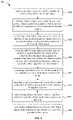
- FIG. 9shows a simplified flowchart illustrating a method of three-dimensional imaging using a lidar system according to an embodiment of the present invention.
- the present inventionrelates generally to lidar systems for three-dimensional imaging. More specifically, the present invention relates to scanning lidar systems and methods of three-dimensional imaging using inexpensive flexures that are suitable for autonomous vehicles, drones and other applications.
- embodiments of the present inventionprovide scanning lidar systems that comprise a plurality of laser sources and a plurality of photodetectors configured to be scanned synchronously to provide a desired angular field of view.
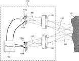
- FIG. 1illustrates schematically a lidar system 100 for three-dimensional imaging according to an embodiment of the present invention.
- the lidar system 100includes an emitting lens 130 and a receiving lens 140 , both being fixed.
- the lidar system 100includes a laser source 110 a disposed substantially in a back focal plane of the emitting lens 130 .
- the laser source 110 ais operative to emit a laser pulse 120 from a respective emission location in the back focal plane of the emitting lens 130 .
- the emitting lens 130is configured to collimate and direct the laser pulse 120 toward an object 150 located in front of the lidar system 100 .
- the collimated laser pulse 120 ′is directed at a corresponding angle toward the object 150 .
- a portion 122 of the laser pulse 120is reflected off of the object 150 toward the receiving lens 140 .
- the receiving lens 140is configured to focus the portion 122 of the laser pulse 120 reflected off of the object 150 onto a corresponding detection location in the focal plane of the receiving lens 140 .
- the lidar system 100further includes a photodetector 160 a disposed substantially at the focal plane of the receiving lens 140 .
- the photodetector 160 ais configured to receive and detect the portion 122 of the laser pulse 120 reflected off of the object at the corresponding detection location.
- the corresponding detection location of the photodetector 160 ais conjugate with the respective emission location of the laser source 110 a.
- the laser pulse 120may be of a short duration, for example, 100 ns pulse width.
- the lidar system 100further includes a processor 190 coupled to the laser source 110 a and the photodetector 160 a .
- the processor 190is configured to determine a time of flight (TOF) of the laser pulse 120 from emission to detection. Since the laser pulse 120 travels at the speed of light, a distance between the lidar system 100 and the object 150 may be determined based on the determined time of flight.
- TOFtime of flight
- the laser source 120 amay be raster scanned to a plurality of emission locations in the back focal plane of the emitting lens 130 , and is configured to emit a plurality of laser pulses at the plurality of emission locations.
- Each laser pulse emitted at a respective emission locationis collimated by the emitting lens 130 and directed at a respective angle toward the object 150 , and incidents at a corresponding point on the surface of the object 150 .
- the laser source 120 ais raster scanned within a certain area in the back focal plane of the emitting lens 130 , a corresponding object area on the object 150 is scanned.
- the photodetector 160 ais raster scanned to a plurality of corresponding detection locations in the focal plane of the receiving lens 140 .
- the scanning of the photodetector 160 ais performed synchronously with the scanning of the laser source 110 a , so that the photodetector 160 a and the laser source 110 a are always conjugate with each other at any given time.
- the distance from the lidar system 100 to each corresponding point on the surface of the object 150may be determined.
- the processor 190is coupled with a position encoder that detects the position of the laser source 110 a at each emission location. Based on the emission location, the angle of the collimated laser pulse 120 ′ may be determined. The X-Y coordinate of the corresponding point on the surface of the object 150 may be determined based on the angle and the distance to the lidar system 100 .
- a three-dimensional image of the object 150may be constructed based on the measured distances from the lidar system 100 to various points on the surface of the object 150 .
- the three-dimensional imagemay be represented as a point cloud, i.e., a set of X, Y, and Z coordinates of the points on the surface of the object 150 .
- the intensity of the return laser pulseis measured and used to adjust the power of subsequent laser pulses from the same emission point, in order to prevent saturation of the detector, improve eye-safety, or reduce overall power consumption.
- the power of the laser pulsemay be varied by varying the duration of the laser pulse, the voltage or current applied to the laser, or the charge stored in a capacitor used to power the laser. In the latter case, the charge stored in the capacitor may be varied by varying the charging time, charging voltage, or charging current to the capacitor.
- the intensitymay also be used to add another dimension to the image.
- the imagemay contain X, Y, and Z coordinates, as well as reflectivity (or brightness).
- the angular field of view (AFOV) of the lidar system 100may be estimated based on the scanning range of the laser source 110 a and the focal length of the emitting lens 130 as,
- the lidar system 100may include multiple laser sources disposed as an array at the back focal plane of the emitting lens 130 , so that a larger total AFOV may be achieved while keeping the scan range of each individual laser source relatively small.
- the lidar system 100may include multiple photodetectors disposed as an array at the focal plane of the receiving lens 140 , each photodetector being conjugate with a respective laser source.
- the lidar system 100may include a second laser source 110 b and a second photodetector 160 b , as illustrated in FIG. 1 .
- the lidar system 100may include four laser sources and four photodetectors, or eight laser sources and eight photodetectors.
- the lidar system 100may include 8 laser sources arranged as a 4 ⁇ 2 array and 8 photodetectors arranged as a 4 ⁇ 2 array, so that the lidar system 100 may have a wider AFOV in the horizontal direction than its AFOV in the vertical direction.
- the total AFOV of the lidar system 100may range from about 5 degrees to about 15 degrees, or from about 15 degrees to about 45 degrees, or from about 45 degrees to about 90 degrees, depending on the focal length of the emitting lens, the scan range of each laser source, and the number of laser sources.
- the laser source 110 amay be configured to emit laser pulses in the ultraviolet, visible, or near infrared wavelength ranges.
- the energy of each laser pulsemay be in the order of microjoules, which is normally considered to be “eye-safe.” For laser sources operating in wavelengths greater than about 1500 nm, the energy levels could be higher as the eye does not focus at those wavelengths.
- the photodetector 160 amay comprise a silicon avalanche photodiode, a photomultiplier, a PIN diode, or other semiconductor sensors.
- the laser sources and the photodetectorsmay be scanned using relatively low-cost flexure mechanisms, as described below.
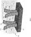
- FIG. 2illustrates schematically a flexure mechanism 200 that may be used for scanning the one or more laser sources 110 a and 110 b and the one or more photodetectors 160 a and 160 b in the lidar system 100 illustrated in FIG. 1 , according to an embodiment of the present invention.
- the flexure mechanism 200includes a fixed base 210 , a first flexure 220 , and a second flexure 222 .
- the base end of each of the first flexure 220 and the second flexure 222are attached to the base 210 .
- a first platform 230is attached to the free end of the first flexure 230 for mounting one or more laser sources 110 a and 110 b thereon.
- a second platform 232is attached to the free end of the second flexure 232 for mounting one or more photodetectors 160 a and 160 b thereon.
- the first flexure 220is configured such that its free end may be deflected laterally when actuated, thereby translating the one or more laser sources 110 a and 110 b substantially in the back focal plane of the emitting lens 130 .
- the second flexure 222is configured such that its free end may be deflected laterally when actuated, thereby translating the one or more photodetectors 160 a and 160 b substantially in the focal plane of the receiving lens 140 .
- the free end of the first flexure 220 and the free end of the second flexure 222are mechanically linked with each other through a tie bar 240 , so that the distance between each photodetector 160 a or 160 b and the corresponding laser source 110 a or 110 b remains constant as they are being scanned. This would ensure that each photodetector 160 a or 160 b is always conjugate with the corresponding laser source 110 a or 110 b , provided that the lens prescriptions for the emitting lens 130 and the receiving lens 140 are essentially identical.
- the first flexure 220 and the second flexure 222may be actuated by a single actuator. For example, they may be actuated simultaneously by the voice coils 260 and 262 and the permanent magnets 250 and 252 as illustrated in FIG. 2 .
- the voice coils 260 and 262When the voice coils 260 and 262 are energized, the first flexure 220 and the second flexure 222 may be deflected by the magnetic force in the desired direction.
- the voice coils 260 and 262may be operated from direct current (DC) to a frequency significantly above the resonance frequency of the flexure assembly. In one embodiment, they may be operated at the resonance frequency.
- DCdirect current
- the magnets 250 and 252are held fixed while the coils 260 and 262 move.
- the first flexure 220 and the second flexure 222may be actuated by other types of actuators, such as piezoelectric actuators and cams driven by electric motors, and the like.
- actuatorssuch as piezoelectric actuators and cams driven by electric motors, and the like.
- the lidar system 100may include a position encoder 270 located behind the second platform 232 .
- the position encoder 270may be configured to detect the positions of the photodetector 160 a with respect to a reference position.
- the position encoder 270may input the positions of the photodetector 160 a to the processor 190 .
- the processor 190may determine the positions of the laser source 110 a based on the positions of the photodetector 160 a , since the position of the laser source 110 a and the position of the photodetector 160 a are always conjugate with each other.
- the processor 190may use the positions of the laser source 110 a to construct the three-dimensional image of the object 150 .
- the position encoder 270may be positioned behind the first platform 230 and configured to detect the positions of the laser source 160 a with respect to a reference position, and may input the positions of the laser source 110 a to the processor 190 .
- the position encoder 270may be a magnetic encoder, an optical encoder, a capacitive sensor, a Hall sensor, or any other encoder type known to those skilled in the art.
- FIG. 3illustrates schematically a flexure mechanism 300 that may be used for scanning the laser sources 110 a and 110 b and the photodetectors 160 a and 160 b in the lidar system 100 illustrated in FIG. 1 , according to another embodiment of the present invention.
- the flexure mechanism 300Similar to the flexure mechanism 200 , the flexure mechanism 300 includes a fixed base 310 , a first flexure 320 , and a second flexure 322 . Each of the base end of the first flexure 320 and the base end of the second flexure 322 are attached to the base 310 .
- a first platform 330is attached to the free end of the first flexure 320 for mounting one or more laser sources 110 a and 110 b thereon.
- a second platform 332is attached to the free end of the second flexure 322 for mounting one or more photodetectors 160 a and 160 b thereon.
- the free end of the first flexure 320 and the free end of the second flexure 322are not mechanically linked, and they are actuated by separate actuators.
- the first flexure 320may be actuated by the voice coils 360 and 362 , and the permanent magnet 350 ;
- the second flexure 322may be actuated by the voice coils 364 and 366 , and the permanent magnet 352 , as illustrated in FIG. 3 .
- other types of actuatorssuch as piezoelectric actuators and cams driven by electric motors, and the like, may be used.
- the first flexure 320 and the second flexure 322may be actuated synchronously using an electronic control circuitry so that the position of each photodetector 160 a or 160 b is always conjugate with the position of the corresponding laser source 110 a or 110 b .
- the lidar system 100further includes a first position encoder 370 located behind the first platform 330 for detecting positions of the laser source 110 a with respect to a reference position, and a second position encoder 372 located behind the second platform 332 for detecting positions of the photodetector 160 a with respect to a reference position.
- the first position encoder 370 and the second position encoder 372may be coupled to the processor 190 .
- the processor 190may generate an electronic feedback signal based on a comparison between the position of the laser source 110 a and the position of the photodetector 160 a , and uses the electronic feedback signal to synchronize the actuation of the first flexure 320 and the actuation of the second flexure 322 , so that the position of the laser source 110 a and the position of the photodetector 160 a are always conjugate with each other.
- the flexure mechanism 200 illustrated in FIG. 2may be configured to scan the laser source 110 a and the photodetector 160 a in two dimensions.
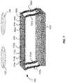
- FIG. 4illustrates schematically a perspective view of the flexure mechanism 300 .
- the first flexure 320 and the second flexure 322are essentially cantilevers with their base ends fixed to the base 310 .
- Each of the free end of the first flexure 320 and the free end of the second flexure 322may be deflected in the vertical direction as well as in the horizontal direction, as indicated by the arrows in FIG. 4 .
- the first flexure 320 and the second flexure 322may be raster scanned in the horizontal direction with a first speed, and raster scanned in the vertical direction with a second speed less than the first speed, or vice versa.
- actuation and control of the raster scanningmay be accomplished. It should be understood that, although a single laser source 110 a and a single photodetector 160 a are shown in FIG. 4 , a plurality of laser sources may be mounted on the platform 330 attached to the first flexure 320 , and a plurality of photodetectors may be mounted on the platform 332 attached to the second flexure 332 .
- FIG. 5illustrates schematically a counter-balancing flexure mechanism 500 according to an embodiment of the present invention.
- the flexure mechanism 500includes a base 510 , a first flexure 520 a and a second flexure 520 b disposed side-by-side, a third flexure 522 a and a fourth flexure 522 b disposed side-by-side.
- each of the flexures 520 a , 520 b , 522 a , and 522 bis attached to the base 510 .
- One or more laser sources 110 aare attached to the free end of the first flexure 520 a
- one or more laser sources 110 bare attached to the free end of the second flexure 520 b
- One or more photodetectors 160 aare attached to the free end of the third flexure 522 a
- one or more photodetectors 160 bare attached to the free end of the fourth flexure 522 b .
- the first flexure 520 a and the third flexure 522 amove in opposite directions with respect to the second flexure 520 b and the fourth flexure 522 b , both in the left-right direction and in the forward-backward direction. That is, at a given time, the first flexure 520 a and the third flexure 522 a may move to the left and forward, while the second flexure 520 b and the fourth flexure 522 b may move to the right and backward, as illustrated in FIG. 5 .
- the motion of the first flexure 520 amay counter balance the motion of the second flexure 520 b
- the motion of the third flexure 522 amay counter balance the motion of the fourth flexure 522 b , thereby canceling most of the vibrations.
- the movement of the first flexure 520 a and the movement of the third flexure 522 aare synchronized such that the position of the laser source 110 a and the position of the photodetector 160 a are always conjugate with respect to each other.
- the movement of the second flexure 520 b and the movement of the fourth flexure 522 bare synchronized such that the position of the laser source 110 b and the position of the photodetector 160 b are always conjugate with respect to each other.
- the counter-balancing motions of the flexures 520 a , 520 b , 522 a , and 522 bmay be achieved by using electrical control signals from the processor 190 .
- dummy flexuresmay be used for vibration cancellation.
- FIG. 6illustrates schematically a flexure mechanism 600 that may be used for scanning one or more laser sources 110 a - 110 d and one or more photodetectors 160 a - 160 d in the lidar system 100 illustrated in FIG. 1 , according to another embodiment of the present invention.
- four laser sources 110 a - 110 d and four photodetectors 160 a - 160 dare mounted on a same rigid platform 630 .
- the positions of the laser sources 110 a - 110 d and the photodetectors 160 a - 160 dare arranged such that each laser source 110 a , 110 b , 110 c , or 110 d is spatially conjugate with a corresponding photodetector 160 a , 160 b , 160 c , or 160 d .
- the platform 630is coupled to a first base plate 610 by a first flexure comprising two flexure elements 620 a and 620 b .
- the flexure elements 620 a and 620 bmay be deflected to the left or right by using a single actuator, such as the voice coil 650 and permanent magnet 660 as shown in FIG.
- the first base plate 610may be coupled to a second base plate 612 by a second flexure comprising two flexure elements 670 a and 670 b .
- the flexure elements 670 a and 670 bmay be deflected forward or backward by using a single actuator, such as the voice coil 652 and the permanent magnet 662 as shown in FIG. 6 , or by a piezoelectric actuator, and the like.
- the laser sources 110 a - 110 d and the photodetectors 160 a - 160 dmay be scanned in two dimensions in the focal planes of the emitting lens 130 and the receiving lens 140 , respectively, by the left-right movements of the flexure elements 620 a and 620 b , and by the forward-backward movements of the flexure elements 670 a and 670 b . Because the laser sources 110 a - 110 d and the photodetectors 160 a - 160 d are mounted on the same rigid platform 630 , the conjugate spatial relationship between each laser-photodetector pair is maintained as they are scanned, provided that the lens prescriptions for the emitting lens 130 and the receiving lens 140 are essentially identical.
- laser sources 110 a - 110 d and four photodetectors 160 a - 160 dare shown as an example in FIG. 6
- fewer or more laser sources and fewer or more photodetectorsmay be mounted on a single platform 630 .
- one laser source and one photodetector, or two laser sources and two photodetectors, or eight laser sources and eight photodetectorsmay be mounted on a single platform 630 , according to various embodiments of the present invention.
- eight laser sourcesmay be arranged as a 4 ⁇ 2 array, and eight photodetectors may be arranged as a 4 ⁇ 2 array, all mounted on the same rigid platform 630 .
- a first position encoder 640may be disposed adjacent the platform 630 for detecting coordinates of the laser sources 110 a - 110 d in the left-right direction (i.e., the x-coordinates), and a second position encoder 642 may be disposed adjacent the first base plate 610 for detecting coordinates of the laser sources 110 a - 110 d in the forward-backward direction (i.e., the y-coordinates).
- the first position encoder 640 and the second position encoder 642may input the x-y coordinates of the laser sources 110 a - 110 d to the processor 190 to be used for constructing the three-dimensional image of the object 150 .
- FIG. 7illustrates schematically a flexure mechanism 700 that may be used for scanning one or more laser sources 110 a - 110 d and one or more photodetectors 160 a - 160 d in the lidar system 100 illustrated in FIG. 1 , according to yet another embodiment of the present invention.
- the laser sources 110 a - 110 d and the photodetectors 160 a - 160 dare mounted to the same rigid platform 630 .
- the platform 630is coupled to the fixed base 610 by a flexure comprising four flexure elements 720 a - 720 d .
- the four flexure elements 720 a - 720 dmay be deflected laterally in both the left-right direction and the backward-forward direction, thereby allowing the laser sources 110 a - 110 d and the photodetectors 160 a - 160 d to be scanned in two dimensions. Similar to the flexure mechanism 600 shown in FIG. 6 , because the laser sources 110 a - 110 d and the photodetectors 160 a - 160 d are mounted on the same rigid platform 630 , the conjugate spatial relationship between each laser-photodetector pair is maintained as they are scanned.
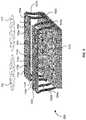
- FIG. 8illustrates schematically a flexure mechanism 800 that may be used for scanning a plurality of laser sources 110 a - 110 h and a plurality of photodetectors 160 a - 160 h in the lidar system 100 illustrated in FIG. 1 , according to a further embodiment of the present invention.
- four laser sources 110 a - 110 d and four photodetectors 160 a - 160 dare mounted on a first rigid platform 630
- another four laser sources 110 e - 110 h and another four photodetectors 160 e - 160 hare mounted on a second rigid platform 632 .
- the first rigid platform 630is coupled to the fixed base 610 by a first flexure comprising four flexure elements 720 a - 720 d .
- the second rigid platform 632is coupled to the fixed base 610 by a second flexure comprising four flexure elements 722 a - 722 d .
- the first platform 630 and the second platform 632are configured to move in opposite directions, so that most of the vibrations may be canceled.
- the first platform 630may move to the left as the second platform 632 moves to the right, as illustrated in FIG. 8 .
- the first platform 630may move to forward as the second platform 632 moves backward.
- more pairs of platforms for additional laser sources and photodetectorsmay be used.
- One of ordinary skill in the artwould recognize many variations, alternatives, and modifications.
- FIG. 9shows a simplified flowchart illustrating a method 900 of three-dimensional imaging using a lidar system, such as the lidar system 100 illustrated in FIG. 1 , according to an embodiment of the present invention.
- the method 900may include, at 902 , translating a laser source to each of a plurality of emission locations in an emission plane, and at 904 , emitting, using the laser source, a plurality of laser pulses. Each of the plurality of laser pulses is emitted at a respective one of the plurality of emission locations.
- the method 900may further include, at 906 , using an emission lens to collimate and direct the plurality of laser pulses towards an object in front of the lidar system. A portion of each of the plurality of laser pulses may be reflected off of the object.
- the method 900may further include, at 908 , using a receiving lens to receive and focus the portion of each of the plurality of laser pulses reflected off of the object to a plurality of corresponding detection locations in a detection plane. Each corresponding detection location is conjugate with a respective emission location.
- the method 900may further include, at 910 , translating a photodetector to each of the plurality of corresponding detection locations in the detection plane, and at 912 , detecting, using the photodetector, the portion of each of the plurality of laser pulses at each of the plurality of detection locations.
- the method 900may further include, at 914 , determining, using a processor, a time of flight for each of the plurality of laser pulses from emission to detection, and at 916 , constructing a three-dimensional image of the object based on the determined time of flight for each of the plurality of laser pulses.
- FIG. 9provides a particular method of performing three-dimensional imaging using a lidar system according to an embodiment of the present invention.
- Other sequences of stepsmay also be performed according to alternative embodiments.
- alternative embodiments of the present inventionmay perform the steps outlined above in a different order.
- the individual steps illustrated in FIG. 9may include multiple sub-steps that may be performed in various sequences as appropriate to the individual step.
- additional stepsmay be added and some steps may be removed depending on the particular applications.
- One of ordinary skill in the artwould recognize many variations, modifications, and alternatives.
- translating the photodetector to each of the plurality of corresponding detection locations in the detection planeis performed synchronously with translating the laser source to each of the plurality of emission locations in the emission plane, such that a location of the photodetector is always conjugate with a location of the laser source at any given time.
- the laser source and the photodetectorare mounted on a same platform, and translating the laser source and translating the photodetector are performed by translating the platform.
- translating the laser source in the emission plane through the plurality of emission locationscomprises raster scanning the laser source in the emission plane
- translating the photodetector in the detection plane through the plurality of corresponding detection locationscomprises raster scanning the photodetector in the detection plane.
- the emission plane and the detection planeare substantially perpendicular to an optical axis of the lidar system. Raster scanning of the laser source may be performed in two-dimensions in the emission plane, and raster scanning of the detector may be performed in two-dimensions in the detector plane.
- raster scanning of the laser source and raster scanning of the photodetector in a first directionmay be performed at a first speed
- raster scanning of the laser source and raster scanning of the photodetector in a second direction orthogonal to the first directionmay be performed at a second speed less than the first speed
- raster scanning of the laser sourcemay result in a position of the laser source as a function of time that follows a sinusoidal waveform, or a triangular waveform, or a sawtooth waveform, or the like.
- the raster scanning of the laser source in a first directionmay result in a position of the laser source in the first direction as a function of time that follows a first waveform
- raster scanning of the laser source in a second directionmay result in a position of the laser source in the second direction as a function of time that follows a second waveform different from the first waveform.
- the intensity of each return laser pulseis measured and used to adjust the power of subsequent laser pulses from the same emission point.
- the power of the laser pulsemay be varied by varying the duration of the laser pulse, the voltage or current applied to the laser, or the charge stored in a capacitor used to power the laser. In the latter case, the charge stored in the capacitor may be varied by varying the charging time, charging voltage, or charging current to the capacitor.
- the intensitymay also be used to add another dimension to the image.
- the imagemay contain X, Y, and Z coordinates, as well as reflectivity (or brightness).
- each laser sourcemay be configured to emit laser pulses at regular time intervals at certain repetition rate, such as 10 kHz or the like.
- the plurality of laser sourcesmay be configured to emit laser pulses simultaneously at same time intervals, or may be configured to emit laser pulses at staggered time intervals, according to various embodiments of the present invention.
- a second laser sourcemay be configured to emit laser pulses also at the pulse repetition rate of 10 kHz, but is staggered with respect to that of the first laser source with a time delay ⁇ t that is less than the time interval ⁇ T between consecutive pulses.
- the electrical signals generated by the first photodetector and the second photodetectormay be input into a single analog-to-digital converter (ADC) in the processor for measuring the times of flight for the trains of pulses emitted by both the first laser source and the second laser source, as long as the time of flight is always shorter than the time between laser pulses.
- ADCanalog-to-digital converter
- the electrical signals generated by the first photodetector and the second photodetectormay be input into separate ADCs.
- the speed of scanningmay vary with the position of the laser source.
- the speed of scanningmay be slower at the extreme ends of the motion than at other positions.
- the laser sourceis configured to emit laser pulses at constant time intervals, the angular spacing between two adjacent laser pulses may vary with the scanning speed.
- the laser sourcemay be configured to emit laser pulses at non-uniform time intervals to compensate for the non-uniformity of scanning speed, so that the angular spacing between two adjacent laser pulses may be independent of the scanning speed.
- the laser sourceis configured to emit laser pulses at constant time intervals regardless of the waveform of the scanning motion.
- a position encodermay measure the positions of the laser source where a series of laser pulses are emitted. The processor may then determine the corresponding angles for the series of laser pulses based on the positions of the laser source.
Landscapes
- Engineering & Computer Science (AREA)
- Physics & Mathematics (AREA)
- General Physics & Mathematics (AREA)
- Remote Sensing (AREA)
- Computer Networks & Wireless Communication (AREA)
- Radar, Positioning & Navigation (AREA)
- Electromagnetism (AREA)
- Multimedia (AREA)
- Theoretical Computer Science (AREA)
- Signal Processing (AREA)
- Computer Vision & Pattern Recognition (AREA)
- Optics & Photonics (AREA)
- Mechanical Engineering (AREA)
- Optical Radar Systems And Details Thereof (AREA)
- Length Measuring Devices By Optical Means (AREA)
Abstract
Description
where h is scan range of the
θ=1.22λ/D,
where λ is the wavelength of the laser pulse, and D is the diameter of the lens aperture. According to various embodiments, the angular resolution of the
Claims (20)
Priority Applications (1)
| Application Number | Priority Date | Filing Date | Title |
|---|---|---|---|
| US16/574,616US11300684B2 (en) | 2016-04-26 | 2019-09-18 | Scanning lidar systems for three-dimensional sensing |
Applications Claiming Priority (3)
| Application Number | Priority Date | Filing Date | Title |
|---|---|---|---|
| US201662327447P | 2016-04-26 | 2016-04-26 | |
| US15/267,558US10451740B2 (en) | 2016-04-26 | 2016-09-16 | Scanning lidar systems for three-dimensional sensing |
| US16/574,616US11300684B2 (en) | 2016-04-26 | 2019-09-18 | Scanning lidar systems for three-dimensional sensing |
Related Parent Applications (1)
| Application Number | Title | Priority Date | Filing Date |
|---|---|---|---|
| US15/267,558ContinuationUS10451740B2 (en) | 2016-04-26 | 2016-09-16 | Scanning lidar systems for three-dimensional sensing |
Publications (2)
| Publication Number | Publication Date |
|---|---|
| US20200096642A1 US20200096642A1 (en) | 2020-03-26 |
| US11300684B2true US11300684B2 (en) | 2022-04-12 |
Family
ID=60088474
Family Applications (4)
| Application Number | Title | Priority Date | Filing Date |
|---|---|---|---|
| US15/267,558Active2038-01-10US10451740B2 (en) | 2016-04-26 | 2016-09-16 | Scanning lidar systems for three-dimensional sensing |
| US15/288,206Active2038-01-30US10481266B2 (en) | 2016-04-26 | 2016-10-07 | Multi-range three-dimensional imaging systems |
| US15/389,368Active2037-12-05US10754036B2 (en) | 2016-04-26 | 2016-12-22 | Scanning illuminated three-dimensional imaging systems |
| US16/574,616Active2037-01-27US11300684B2 (en) | 2016-04-26 | 2019-09-18 | Scanning lidar systems for three-dimensional sensing |
Family Applications Before (3)
| Application Number | Title | Priority Date | Filing Date |
|---|---|---|---|
| US15/267,558Active2038-01-10US10451740B2 (en) | 2016-04-26 | 2016-09-16 | Scanning lidar systems for three-dimensional sensing |
| US15/288,206Active2038-01-30US10481266B2 (en) | 2016-04-26 | 2016-10-07 | Multi-range three-dimensional imaging systems |
| US15/389,368Active2037-12-05US10754036B2 (en) | 2016-04-26 | 2016-12-22 | Scanning illuminated three-dimensional imaging systems |
Country Status (5)
| Country | Link |
|---|---|
| US (4) | US10451740B2 (en) |
| EP (1) | EP3449274A4 (en) |
| JP (2) | JP7108308B2 (en) |
| CN (1) | CN109416399B (en) |
| WO (1) | WO2017189185A1 (en) |
Cited By (1)
| Publication number | Priority date | Publication date | Assignee | Title |
|---|---|---|---|---|
| US20190162858A1 (en)* | 2017-11-30 | 2019-05-30 | Cepton Technologies, Inc. | Detector designs for improved resolution in lidar systems |
Families Citing this family (146)
| Publication number | Priority date | Publication date | Assignee | Title |
|---|---|---|---|---|
| US11493634B2 (en) | 2015-02-13 | 2022-11-08 | Carnegie Mellon University | Programmable light curtains |
| US11972586B2 (en) | 2015-02-13 | 2024-04-30 | Carnegie Mellon University | Agile depth sensing using triangulation light curtains |
| US11425357B2 (en)* | 2015-02-13 | 2022-08-23 | Carnegie Mellon University | Method for epipolar time of flight imaging |
| US11747135B2 (en) | 2015-02-13 | 2023-09-05 | Carnegie Mellon University | Energy optimized imaging system with synchronized dynamic control of directable beam light source and reconfigurably masked photo-sensor |
| US12123950B2 (en) | 2016-02-15 | 2024-10-22 | Red Creamery, LLC | Hybrid LADAR with co-planar scanning and imaging field-of-view |
| US12399279B1 (en) | 2016-02-15 | 2025-08-26 | Red Creamery Llc | Enhanced hybrid LIDAR with high-speed scanning |
| US12399278B1 (en) | 2016-02-15 | 2025-08-26 | Red Creamery Llc | Hybrid LIDAR with optically enhanced scanned laser |
| US11556000B1 (en) | 2019-08-22 | 2023-01-17 | Red Creamery Llc | Distally-actuated scanning mirror |
| US9866816B2 (en) | 2016-03-03 | 2018-01-09 | 4D Intellectual Properties, Llc | Methods and apparatus for an active pulsed 4D camera for image acquisition and analysis |
| US10761195B2 (en) | 2016-04-22 | 2020-09-01 | OPSYS Tech Ltd. | Multi-wavelength LIDAR system |
| US10451740B2 (en) | 2016-04-26 | 2019-10-22 | Cepton Technologies, Inc. | Scanning lidar systems for three-dimensional sensing |
| USD832845S1 (en)* | 2016-08-01 | 2018-11-06 | Hand Held Products, Inc. | Optical scanner |
| DE102016220468A1 (en)* | 2016-10-19 | 2018-04-19 | Robert Bosch Gmbh | Lidar sensor for detecting an object |
| DE102016220504A1 (en)* | 2016-10-19 | 2018-04-19 | Robert Bosch Gmbh | 3D LIDAR sensor |
| US10684358B2 (en)* | 2016-11-11 | 2020-06-16 | Raytheon Company | Situational awareness sensor using a fixed configuration of optical phased arrays (OPAs) |
| IT201700021559A1 (en)* | 2017-02-27 | 2018-08-27 | St Microelectronics Srl | CORRESPONDENT PROCEDURE FOR THE CONTROL OF LASER RAYS, DEVICE, EQUIPMENT AND COMPUTER PRODUCT |
| KR102619582B1 (en) | 2017-03-13 | 2024-01-02 | 옵시스 테크 엘티디 | Eye-Safe Scanning LIDAR System |
| US10114111B2 (en)* | 2017-03-28 | 2018-10-30 | Luminar Technologies, Inc. | Method for dynamically controlling laser power |
| US20180284246A1 (en)* | 2017-03-31 | 2018-10-04 | Luminar Technologies, Inc. | Using Acoustic Signals to Modify Operation of a Lidar System |
| US10677897B2 (en) | 2017-04-14 | 2020-06-09 | Luminar Technologies, Inc. | Combining lidar and camera data |
| KR102218679B1 (en) | 2017-07-28 | 2021-02-23 | 옵시스 테크 엘티디 | VCSEL Array LIDAR Transmitter with Small Angle Divergence |
| US10346994B2 (en)* | 2017-07-29 | 2019-07-09 | Verizon Patent And Licensing Inc. | Systems and methods for inward-looking depth scanning of a real-world scene |
| US10317905B2 (en)* | 2017-08-10 | 2019-06-11 | RavenOPS, Inc. | Autonomous robotic technologies for industrial inspection |
| US11460550B2 (en) | 2017-09-19 | 2022-10-04 | Veoneer Us, Llc | Direct detection LiDAR system and method with synthetic doppler processing |
| EP3460518B1 (en)* | 2017-09-22 | 2024-03-13 | Leica Geosystems AG | Hybrid lidar-imaging device for aerial surveying |
| JP7117092B2 (en)* | 2017-09-25 | 2022-08-12 | 株式会社トプコン | LASER MEASUREMENT METHOD AND LASER MEASUREMENT DEVICE |
| US11194022B2 (en) | 2017-09-29 | 2021-12-07 | Veoneer Us, Inc. | Detection system with reflection member and offset detection array |
| US10921431B2 (en) | 2017-10-19 | 2021-02-16 | Cepton Technologies Inc. | Apparatuses for scanning a lidar system in two dimensions |
| USD848428S1 (en)* | 2017-11-08 | 2019-05-14 | Lee Seng Fook | Hand held 3D scanning device |
| USD848429S1 (en)* | 2017-11-08 | 2019-05-14 | Lee Seng Fook | Hand held 3D scanning device with feedback system |
| US11585901B2 (en) | 2017-11-15 | 2023-02-21 | Veoneer Us, Llc | Scanning lidar system and method with spatial filtering for reduction of ambient light |
| EP3710855A4 (en) | 2017-11-15 | 2021-08-04 | Opsys Tech Ltd. | Noise adaptive solid-state lidar system |
| US10816666B2 (en)* | 2017-11-21 | 2020-10-27 | Magna Electronics Inc. | Vehicle sensing system with calibration/fusion of point cloud partitions |
| DE102017221797A1 (en)* | 2017-12-04 | 2019-06-06 | Osram Gmbh | Lidar system for environment detection and method for operating a lidar system |
| CN109884656B (en)* | 2017-12-06 | 2021-05-28 | 北京万集科技股份有限公司 | Lidar and ranging method for realizing scanning field of view division |
| CN109313822B (en)* | 2017-12-13 | 2020-04-10 | 广州艾若博机器人科技有限公司 | Virtual wall construction method and device based on machine vision, map construction method and movable electronic equipment |
| US11662433B2 (en) | 2017-12-22 | 2023-05-30 | Denso Corporation | Distance measuring apparatus, recognizing apparatus, and distance measuring method |
| CN108254736B (en)* | 2017-12-31 | 2022-05-13 | 天津木牛流马科技发展股份有限公司 | Submillimeter-level laser radar |
| CN108241146A (en)* | 2018-01-15 | 2018-07-03 | 深圳市速腾聚创科技有限公司 | Laser radar and the method for improving laser radar launch point frequency |
| EP4321898A3 (en)* | 2018-01-17 | 2024-04-24 | Hesai Technology Co., Ltd. | Detection device and method for adjusting parameter thereof |
| DE102018201508B4 (en)* | 2018-02-01 | 2021-03-18 | Robert Bosch Gmbh | Use in a LiDAR system of a method for operating a LiDAR system by emitting laser light in the form of laser pulses |
| US10771690B2 (en)* | 2018-02-10 | 2020-09-08 | Goodrich Corporation | Distributed aperture systems for obstacle avoidance |
| US11592527B2 (en) | 2018-02-16 | 2023-02-28 | Cepton Technologies, Inc. | Systems for incorporating LiDAR sensors in a headlamp module of a vehicle |
| US20190285734A1 (en)* | 2018-03-14 | 2019-09-19 | Infineon Technologies Ag | Detection system with configurable range and field of view |
| KR102604050B1 (en) | 2018-04-01 | 2023-11-22 | 옵시스 테크 엘티디 | Noise adaptive solid-state lidar system |
| CN112204486B (en)* | 2018-04-03 | 2024-08-09 | 尚科宁家运营有限公司 | Time-of-flight sensor arrangement for robot navigation and method for positioning using the same |
| US10694168B2 (en)* | 2018-04-22 | 2020-06-23 | Corephotonics Ltd. | System and method for mitigating or preventing eye damage from structured light IR/NIR projector systems |
| KR102466555B1 (en) | 2018-06-14 | 2022-11-14 | 현대모비스 주식회사 | Lidar sensor and control method thereof |
| DE102018131201A1 (en)* | 2018-06-21 | 2019-12-24 | pmdtechnologies ag | Time-of-flight camera system with an adjustable optical output power |
| CN109116331B (en)* | 2018-06-27 | 2020-04-24 | 上海禾赛光电科技有限公司 | Coding laser transceiver, distance measuring device and laser radar system |
| US10466342B1 (en) | 2018-09-30 | 2019-11-05 | Hesai Photonics Technology Co., Ltd. | Adaptive coding for lidar systems |
| JP7077822B2 (en) | 2018-07-05 | 2022-05-31 | 株式会社デンソー | Optical range measuring device |
| US11822020B2 (en) | 2018-07-10 | 2023-11-21 | Cepton Technologies, Inc. | Scanning lidar systems with moving lens assembly |
| US20200019192A1 (en) | 2018-07-13 | 2020-01-16 | Caterpillar Paving Products Inc. | Object detection and implement position detection system |
| US10627516B2 (en) | 2018-07-19 | 2020-04-21 | Luminar Technologies, Inc. | Adjustable pulse characteristics for ground detection in lidar systems |
| DE102018118584A1 (en) | 2018-07-31 | 2020-02-06 | Blickfeld GmbH | Vehicle headlights with LIDAR module |
| CN110850859B (en)* | 2018-08-01 | 2023-03-07 | 深圳市优必选科技有限公司 | Robot and obstacle avoidance method and obstacle avoidance system thereof |
| JP2021532368A (en) | 2018-08-03 | 2021-11-25 | オプシス テック リミテッド | Distributed modular solid-state lidar system |
| GB2579689A (en)* | 2018-08-07 | 2020-07-01 | Cambridge Mechatronics Ltd | Improved 3D sensing |
| EP3627175B1 (en) | 2018-09-19 | 2020-07-22 | Sick Ag | Optoelectronic sensor and method for deflecting a beam of light |
| JP7242234B2 (en)* | 2018-09-28 | 2023-03-20 | キヤノン株式会社 | Photodetector, photodetection system |
| DE102018216707A1 (en)* | 2018-09-28 | 2020-04-02 | Ibeo Automotive Systems GmbH | Environment detection system and method for an environment detection system |
| US20200103504A1 (en)* | 2018-10-02 | 2020-04-02 | GM Global Technology Operations LLC | Multiple photonic chip lidar system architecture |
| US11269065B2 (en)* | 2018-11-19 | 2022-03-08 | Infineon Technologies Ag | Muilti-detector with interleaved photodetector arrays and analog readout circuits for lidar receiver |
| DE102018220227A1 (en)* | 2018-11-26 | 2020-05-28 | Robert Bosch Gmbh | LIDAR sensor and method for optically detecting a field of view |
| KR102806085B1 (en)* | 2018-12-03 | 2025-05-12 | 삼성전자주식회사 | LiDAR device and method of driving the same |
| US11423572B2 (en) | 2018-12-12 | 2022-08-23 | Analog Devices, Inc. | Built-in calibration of time-of-flight depth imaging systems |
| CN111381246B (en)* | 2018-12-27 | 2025-07-11 | 武汉万集光电技术有限公司 | Laser radar receiving component and laser radar system |
| US11374041B2 (en)* | 2019-01-25 | 2022-06-28 | Cepton Technologies, Inc. | Systems and methods for imaging using mechanical scanning mechanisms |
| CA3173966A1 (en)* | 2019-03-08 | 2020-09-17 | Leddartech Inc. | Lidar system, appartus communicating with the lidar system, and apparatus located in a field of view (fov) of the lidar system |
| JP2020153798A (en)* | 2019-03-19 | 2020-09-24 | 株式会社リコー | Optical device, range finder optical system unit, range finder and range finder system |
| JP2020153796A (en) | 2019-03-19 | 2020-09-24 | 株式会社リコー | Distance measuring device and distance measuring method |
| US11467270B2 (en)* | 2019-03-27 | 2022-10-11 | Asmpt Singapore Pte. Ltd. | Apparatus and method for calibrating or testing an imaging device |
| CN113692540B (en) | 2019-04-09 | 2025-06-17 | 欧普赛斯技术有限公司 | Solid-state LIDAR transmitter with laser control |
| CN109991588A (en)* | 2019-04-29 | 2019-07-09 | 北京握奇数据股份有限公司 | A kind of laser radar scanning device |
| CN110244318B (en)* | 2019-04-30 | 2021-08-17 | 深圳市光鉴科技有限公司 | 3D imaging method based on asynchronous ToF discrete point cloud |
| US11568636B2 (en)* | 2019-05-02 | 2023-01-31 | Advanced Geosciences, Inc. | Reflective cable locating system |
| US11480685B2 (en)* | 2019-05-05 | 2022-10-25 | Apple Inc. | Compact optical packaging of LiDAR systems using diffractive structures behind angled interfaces |
| JP2020187079A (en)* | 2019-05-17 | 2020-11-19 | 三菱重工業株式会社 | Laser radar system and traveling body |
| CN110764099A (en)* | 2019-05-24 | 2020-02-07 | Oppo广东移动通信有限公司 | Time-of-flight sensor and computer-readable storage medium |
| US11796643B2 (en) | 2019-05-30 | 2023-10-24 | Microvision, Inc. | Adaptive LIDAR scanning methods |
| JP7603998B2 (en) | 2019-05-30 | 2024-12-23 | オプシス テック リミテッド | Eye-safe long-range LIDAR system using actuators |
| US11828881B2 (en) | 2019-05-30 | 2023-11-28 | Microvision, Inc. | Steered LIDAR system with arrayed receiver |
| US11754682B2 (en)* | 2019-05-30 | 2023-09-12 | Microvision, Inc. | LIDAR system with spatial beam combining |
| US11513195B2 (en) | 2019-06-10 | 2022-11-29 | OPSYS Tech Ltd. | Eye-safe long-range solid-state LIDAR system |
| EP3990943A4 (en) | 2019-06-25 | 2023-07-05 | Opsys Tech Ltd. | Adaptive multiple-pulse lidar system |
| US10955241B2 (en)* | 2019-06-26 | 2021-03-23 | Aurora Flight Sciences Corporation | Aircraft imaging system using projected patterns on featureless surfaces |
| KR20210003003A (en)* | 2019-07-01 | 2021-01-11 | 삼성전자주식회사 | Lidar apparatus and controlling method thereof |
| US11474218B2 (en) | 2019-07-15 | 2022-10-18 | Veoneer Us, Llc | Scanning LiDAR system and method with unitary optical element |
| US11579257B2 (en) | 2019-07-15 | 2023-02-14 | Veoneer Us, Llc | Scanning LiDAR system and method with unitary optical element |
| KR20220038691A (en) | 2019-07-31 | 2022-03-29 | 옵시스 테크 엘티디 | High-Resolution Solid-State LIDAR Transmitter |
| JP2021028594A (en)* | 2019-08-09 | 2021-02-25 | パイオニア株式会社 | Light projecting/receiving device, range finder and rotary body device |
| CN110673114B (en)* | 2019-08-27 | 2023-04-18 | 三赢科技(深圳)有限公司 | Method and device for calibrating depth of three-dimensional camera, computer device and storage medium |
| US11808858B2 (en) | 2019-09-04 | 2023-11-07 | Pony Ai Inc. | Systems and methods for constructing and utilizing field-of-view (FOV) information |
| US11639846B2 (en) | 2019-09-27 | 2023-05-02 | Honeywell International Inc. | Dual-pattern optical 3D dimensioning |
| US11450083B2 (en) | 2019-09-27 | 2022-09-20 | Honeywell International Inc. | Dual-pattern optical 3D dimensioning |
| US11150348B2 (en) | 2019-10-02 | 2021-10-19 | Cepton Technologies, Inc. | Techniques for detecting cross-talk interferences in lidar imaging sensors |
| US11598217B2 (en)* | 2019-10-17 | 2023-03-07 | Dassault Systemes Simulia Corp. | Method for automatic calculation of axial cooling fan shroud circular opening size |
| DE102019217165A1 (en)* | 2019-11-07 | 2021-05-12 | Robert Bosch Gmbh | Operating method and control unit for a LiDAR system, LiDAR system and device |
| US11644303B2 (en) | 2019-12-16 | 2023-05-09 | Faro Technologies, Inc. | Three-dimensional coordinate measuring instrument coupled to a camera having a diffractive optical element |
| US20230028749A1 (en)* | 2019-12-20 | 2023-01-26 | Ams Sensors Asia Pte. Ltd | Lidar with multi-range channels |
| WO2021126082A1 (en)* | 2019-12-20 | 2021-06-24 | Ams Sensors Asia Pte. Ltd. | Eye-safe operation of lidar scanner |
| RU2762744C2 (en) | 2019-12-23 | 2021-12-22 | Общество с ограниченной ответственностью "Яндекс Беспилотные Технологии" | METHODS AND SYSTEMS FOR DETECTING USING LIDAR (LiDAR) WITH FIBER-OPTICAL MATRIX |
| US12085647B2 (en)* | 2019-12-27 | 2024-09-10 | Waymo Llc | LIDAR occlusion detection methods and systems |
| US12313784B2 (en) | 2019-12-30 | 2025-05-27 | Cepton Technologies, Inc. | Half and quarter lissajous scan patterns for LiDAR |
| CN116017164B (en)* | 2019-12-30 | 2024-12-27 | 马特波特公司 | System and method for capturing and generating panoramic three-dimensional images |
| CN111103297B (en)* | 2020-01-20 | 2024-07-12 | 无锡市建筑工程质量检测中心 | Non-contact detection method and detection system for quality of building exterior wall surface layer |
| KR102550678B1 (en)* | 2020-01-22 | 2023-07-04 | 노다르 인크. | Non-Rigid Stereo Vision Camera System |
| US11427193B2 (en) | 2020-01-22 | 2022-08-30 | Nodar Inc. | Methods and systems for providing depth maps with confidence estimates |
| JP7283413B2 (en)* | 2020-02-17 | 2023-05-30 | 株式会社デンソー | IN-VEHICLE MEASURING DEVICE UNIT AND INTEGRATED DATA GENERATION METHOD IN IN-VEHICLE MEASURING DEVICE UNIT |
| JP2021148746A (en)* | 2020-03-23 | 2021-09-27 | 株式会社リコー | Distance measuring device and distance measuring method |
| DE102020110142A1 (en)* | 2020-04-14 | 2021-10-14 | Scantinel Photonics GmbH | Device and method for the scanning measurement of the distance to an object |
| WO2022006158A1 (en)* | 2020-06-29 | 2022-01-06 | Brain Corporation | Systems, apparatuses, and methods for calibrating lidar sensors of a robot using intersecting lidar sensors |
| US20230237766A1 (en)* | 2020-07-08 | 2023-07-27 | Michigan Scientific Corporation | Speed And Slip Determinations For A Vehicle Using Optical Flow Technology |
| CN111766949B (en)* | 2020-07-16 | 2021-08-03 | 腾讯科技(深圳)有限公司 | Three-dimensional image display device, display method, electronic device, and storage medium |
| US11698447B2 (en)* | 2020-07-17 | 2023-07-11 | Infineon Technologies Ag | Beam steering aware pixel clustering of segmented sensor area and implementing averaging algorithms for pixel processing |
| KR20230054612A (en)* | 2020-08-28 | 2023-04-25 | 헤사이 테크놀로지 씨오., 엘티디. | Laser radar and distance measurement methods |
| CN114594486B (en)* | 2020-12-04 | 2025-05-30 | 上海禾赛科技有限公司 | Method, processor and laser radar system for filtering out drag points in radar point cloud |
| US12079673B2 (en) | 2021-02-12 | 2024-09-03 | Scandit Ag | Optical pattern decoding in a real scene using overlay functionality |
| US12175327B1 (en) | 2020-12-04 | 2024-12-24 | Scandit Ag | Camera start optimization for optical pattern decoding |
| CN112684456B (en)* | 2020-12-22 | 2024-05-17 | 安徽配隆天环保科技有限公司 | Unmanned aerial vehicle ultrasonic three-dimensional imaging model system |
| US12044800B2 (en) | 2021-01-14 | 2024-07-23 | Magna Electronics, Llc | Scanning LiDAR system and method with compensation for transmit laser pulse effects |
| KR20230150978A (en)* | 2021-02-23 | 2023-10-31 | 뉴럴 프로펄전 시스템즈, 인크. | Lidar systems and methods with improved eye safety |
| US11326758B1 (en) | 2021-03-12 | 2022-05-10 | Veoneer Us, Inc. | Spotlight illumination system using optical element |
| CN113109789B (en)* | 2021-04-09 | 2024-07-09 | 深圳煜炜光学科技有限公司 | Multi-line scanning laser radar device and control method |
| US11922799B2 (en)* | 2021-04-17 | 2024-03-05 | Charles R. Crittenden | Apparatus and method for a warning system |
| EP4321897A4 (en)* | 2021-04-29 | 2024-06-05 | Huawei Technologies Co., Ltd. | LASER DETECTION DEVICE AND CONTROL METHOD AND CONTROL DEVICE THEREFOR AND TERMINAL DEVICE |
| CN113189609A (en)* | 2021-05-31 | 2021-07-30 | 阿波罗智联(北京)科技有限公司 | Base, roadside sensing equipment and intelligent transportation system |
| US11732858B2 (en) | 2021-06-18 | 2023-08-22 | Veoneer Us, Llc | Headlight illumination system using optical element |
| US20230029105A1 (en)* | 2021-07-21 | 2023-01-26 | Seagate Technology Llc | Fingertip lidar system for visual assistance |
| CN113534191B (en)* | 2021-07-26 | 2022-11-29 | 重庆连芯光电技术研究院有限公司 | 3d image scanning and repairing method, device and equipment of single photon laser radar |
| DE102021208089A1 (en) | 2021-07-27 | 2023-02-02 | Robert Bosch Gesellschaft mit beschränkter Haftung | Method of operating a LiDAR device |
| US11577748B1 (en) | 2021-10-08 | 2023-02-14 | Nodar Inc. | Real-time perception system for small objects at long range for autonomous vehicles |
| CN115015295B (en)* | 2022-05-13 | 2025-08-12 | 中国科学院高能物理研究所 | X-ray detection device and detection method for micro-channel plate collimator |
| CN117518125A (en)* | 2022-07-29 | 2024-02-06 | 深圳市速腾聚创科技有限公司 | Lidar and lidar design methods |
| CN115339384A (en)* | 2022-08-18 | 2022-11-15 | 惠州市德赛西威智能交通技术研究院有限公司 | Vehicle driving assistance system, method, storage medium and vehicle |
| CN115390087A (en)* | 2022-08-24 | 2022-11-25 | 跨维(深圳)智能数字科技有限公司 | Laser line scanning three-dimensional imaging system and method |
| CN115407478B (en)* | 2022-08-25 | 2024-06-25 | 苏州立创致恒电子科技有限公司 | Three-dimensional imaging system and method for self-adaptive detection distance |
| US12092278B2 (en) | 2022-10-07 | 2024-09-17 | Magna Electronics, Llc | Generating a spotlight |
| US12228653B2 (en) | 2022-10-07 | 2025-02-18 | Magna Electronics, Llc | Integrating a sensing system into headlight optics |
| CN115862336B (en)* | 2023-02-27 | 2023-06-02 | 云南省交通规划设计研究院有限公司 | Vehicle running parameter detection device based on double laser sensors |
| CN116466327A (en)* | 2023-03-07 | 2023-07-21 | 深圳信通智能系统技术有限公司 | Laser radar system |
| DE102023205343A1 (en)* | 2023-06-07 | 2024-12-12 | Tripleye Gmbh | Device for spatial image capture of an environment moving relative to the device and operating method therefor |
| CN116973347B (en)* | 2023-07-19 | 2024-02-09 | 哈尔滨工业大学 | An excitation measurement device and application based on SLIPI-3DLIF |
| US12202396B1 (en) | 2023-12-19 | 2025-01-21 | Magna Electronics, Llc | Line-scan-gated imaging for LiDAR headlight |
| DE102024101015A1 (en)* | 2024-01-15 | 2025-07-17 | Cival Medical Gmbh | Medical lighting device |
Citations (14)
| Publication number | Priority date | Publication date | Assignee | Title |
|---|---|---|---|---|
| JP3169074B2 (en) | 1998-09-25 | 2001-05-21 | 日本電気株式会社 | Laser radar device |
| JP2002181533A (en) | 2000-12-18 | 2002-06-26 | Hitachi Ltd | Laser distance measuring device |
| JP2004085225A (en) | 2002-08-23 | 2004-03-18 | Honda Motor Co Ltd | Object detection device |
| US20040141170A1 (en) | 2003-01-21 | 2004-07-22 | Jamieson James R. | System for profiling objects on terrain forward and below an aircraft utilizing a cross-track laser altimeter |
| US20070181810A1 (en)* | 2006-02-06 | 2007-08-09 | Tan Michael R T | Vertical cavity surface emitting laser (VCSEL) array laser scanner |
| US20070279615A1 (en)* | 2006-05-31 | 2007-12-06 | John James Degnan | Scanner/optical system for three-dimensional lidar imaging and polarimetry |
| US20080246943A1 (en) | 2005-02-01 | 2008-10-09 | Laser Projection Technologies, Inc. | Laser radar projection with object feature detection and ranging |
| US20100066995A1 (en) | 2007-03-02 | 2010-03-18 | Peter Rindle | Device and method for the determination of distance by means of light pulses |
| WO2014060562A1 (en) | 2012-10-17 | 2014-04-24 | Cathx Research Ltd | Improvements in relation to underwater imaging for underwater surveys |
| US20150075066A1 (en) | 2013-09-13 | 2015-03-19 | Palo Alto Research Center Incorporated | Unwanted plant removal system having variable optics |
| US20150296201A1 (en) | 2008-11-25 | 2015-10-15 | Tetravue, Inc. | Systems and method of high resolution three-dimensional imaging |
| US20170184399A1 (en) | 2011-06-30 | 2017-06-29 | The Regents Of The University Of Colorado | Remote measurement of shallow depths in semi-transparent media |
| US20170307758A1 (en) | 2016-04-26 | 2017-10-26 | Cepton Technologies, Inc. | Scanning Lidar Systems for Three-Dimensional Sensing |
| US20190301700A1 (en)* | 2015-11-09 | 2019-10-03 | Mitsubishi Electric Corporation | Projection optical instrument and headlight device |
Family Cites Families (32)
| Publication number | Priority date | Publication date | Assignee | Title |
|---|---|---|---|---|
| JPH05288857A (en)* | 1992-04-13 | 1993-11-05 | Nec Corp | Laser radar device |
| JPH0675047A (en)* | 1992-08-25 | 1994-03-18 | Furukawa Electric Co Ltd:The | Optical radar for searching obstacle |
| US6629641B2 (en)* | 2000-06-07 | 2003-10-07 | Metrologic Instruments, Inc. | Method of and system for producing images of objects using planar laser illumination beams and image detection arrays |
| US5852492A (en)* | 1996-06-07 | 1998-12-22 | Lockheed Martin Vought Systems Corp. | Fused lasar range/intensity image display for a human interpretation of lasar data |
| AU2001279795A1 (en)* | 2000-08-01 | 2002-02-13 | Mirko Essling | Measuring device and measuring method for determining distance and/or position |
| EP1423731B1 (en)* | 2001-08-06 | 2006-10-04 | Siemens Aktiengesellschaft | Method and device for recording a three-dimensional distance-measuring image |
| US6556282B2 (en)* | 2001-09-04 | 2003-04-29 | Rosemount Aerospace, Inc. | Combined LOAS and LIDAR system |
| US7236235B2 (en) | 2004-07-06 | 2007-06-26 | Dimsdale Engineering, Llc | System and method for determining range in 3D imaging systems |
| DE102005034729B3 (en)* | 2005-07-21 | 2007-02-08 | Eads Deutschland Gmbh | Method and lidar system for measuring air turbulence on board aircraft, airports and wind farms |
| US8050863B2 (en)* | 2006-03-16 | 2011-11-01 | Gray & Company, Inc. | Navigation and control system for autonomous vehicles |
| US8027029B2 (en)* | 2007-11-07 | 2011-09-27 | Magna Electronics Inc. | Object detection and tracking system |
| US8119971B2 (en)* | 2008-01-17 | 2012-02-21 | Ball Corporation | Pulse data recorder in which a value held by a bit of a memory is determined by a state of a switch |
| US9041915B2 (en)* | 2008-05-09 | 2015-05-26 | Ball Aerospace & Technologies Corp. | Systems and methods of scene and action capture using imaging system incorporating 3D LIDAR |
| JP5570708B2 (en) | 2008-05-29 | 2014-08-13 | オムロンオートモーティブエレクトロニクス株式会社 | Object detection device |
| DE102008031681A1 (en)* | 2008-07-04 | 2010-01-14 | Eads Deutschland Gmbh | LIDAR method for measuring velocities and LIDAR device with timed detection |
| CN101419711B (en)* | 2008-12-15 | 2012-05-30 | 东软集团股份有限公司 | Method and device for estimating vehicle self-motion parameters |
| JP2010164463A (en) | 2009-01-16 | 2010-07-29 | Mitsubishi Electric Corp | Laser three-dimensional image measuring device |
| US8810796B2 (en)* | 2009-04-21 | 2014-08-19 | Michigan Aerospace Corporation | Light processing system and method |
| US8797550B2 (en)* | 2009-04-21 | 2014-08-05 | Michigan Aerospace Corporation | Atmospheric measurement system |
| EP2460034B1 (en)* | 2009-07-29 | 2015-09-09 | Michigan Aerospace Corporation | Atmospheric measurement system |
| US8600606B2 (en)* | 2010-02-11 | 2013-12-03 | GM Global Technology Operations LLC | Vehicle safety systems and methods |
| US8494687B2 (en)* | 2010-03-12 | 2013-07-23 | The United States Of America As Represented By The Administrator Of The National Aeronautics And Space Administration | Method for enhancing a three dimensional image from a plurality of frames of flash LIDAR data |
| US8655513B2 (en)* | 2010-03-12 | 2014-02-18 | The United States Of America As Represented By The Administrator Of The National Aeronautics And Space Administration | Methods of real time image enhancement of flash LIDAR data and navigating a vehicle using flash LIDAR data |
| US9086488B2 (en)* | 2010-04-20 | 2015-07-21 | Michigan Aerospace Corporation | Atmospheric measurement system and method |
| US8558993B2 (en)* | 2010-05-21 | 2013-10-15 | The National Institute of Standards and Technology, as Presented by the Secretary of Commerce | Optical frequency comb-based coherent LIDAR |
| US8736818B2 (en)* | 2010-08-16 | 2014-05-27 | Ball Aerospace & Technologies Corp. | Electronically steered flash LIDAR |
| KR101908304B1 (en)* | 2012-08-10 | 2018-12-18 | 엘지전자 주식회사 | Distance detecting device and Image processing apparatus including the same |
| US9304203B1 (en)* | 2013-03-13 | 2016-04-05 | Google Inc. | Methods, devices, and systems for improving dynamic range of signal receiver |
| US9778363B2 (en)* | 2013-10-24 | 2017-10-03 | Massachusetts Institute Of Technology | Methods and apparatus for coded time-of-flight camera |
| JP2015111090A (en)* | 2013-11-05 | 2015-06-18 | 株式会社リコー | Object detection device |
| JP6338242B2 (en)* | 2014-04-11 | 2018-06-06 | 国立大学法人 東京大学 | Distance image generator |
| CN104459183B (en)* | 2014-12-24 | 2017-07-07 | 四川大学 | A kind of one camera vehicle speed measuring system and method based on Internet of Things |
- 2016
- 2016-09-16USUS15/267,558patent/US10451740B2/enactiveActive
- 2016-10-07USUS15/288,206patent/US10481266B2/enactiveActive
- 2016-12-22USUS15/389,368patent/US10754036B2/enactiveActive
- 2017
- 2017-04-03CNCN201780039604.9Apatent/CN109416399B/enactiveActive
- 2017-04-03WOPCT/US2017/025785patent/WO2017189185A1/ennot_activeCeased
- 2017-04-03JPJP2018557022Apatent/JP7108308B2/enactiveActive
- 2017-04-03EPEP17790087.5Apatent/EP3449274A4/enactivePending
- 2019
- 2019-09-18USUS16/574,616patent/US11300684B2/enactiveActive
- 2022
- 2022-07-08JPJP2022110808Apatent/JP7332210B2/enactiveActive
Patent Citations (17)
| Publication number | Priority date | Publication date | Assignee | Title |
|---|---|---|---|---|
| JP3169074B2 (en) | 1998-09-25 | 2001-05-21 | 日本電気株式会社 | Laser radar device |
| JP2002181533A (en) | 2000-12-18 | 2002-06-26 | Hitachi Ltd | Laser distance measuring device |
| JP2004085225A (en) | 2002-08-23 | 2004-03-18 | Honda Motor Co Ltd | Object detection device |
| US20040141170A1 (en) | 2003-01-21 | 2004-07-22 | Jamieson James R. | System for profiling objects on terrain forward and below an aircraft utilizing a cross-track laser altimeter |
| US20080246943A1 (en) | 2005-02-01 | 2008-10-09 | Laser Projection Technologies, Inc. | Laser radar projection with object feature detection and ranging |
| US20070181810A1 (en)* | 2006-02-06 | 2007-08-09 | Tan Michael R T | Vertical cavity surface emitting laser (VCSEL) array laser scanner |
| US7544945B2 (en) | 2006-02-06 | 2009-06-09 | Avago Technologies General Ip (Singapore) Pte. Ltd. | Vertical cavity surface emitting laser (VCSEL) array laser scanner |
| US20070279615A1 (en)* | 2006-05-31 | 2007-12-06 | John James Degnan | Scanner/optical system for three-dimensional lidar imaging and polarimetry |
| US20100066995A1 (en) | 2007-03-02 | 2010-03-18 | Peter Rindle | Device and method for the determination of distance by means of light pulses |
| US20150296201A1 (en) | 2008-11-25 | 2015-10-15 | Tetravue, Inc. | Systems and method of high resolution three-dimensional imaging |
| US20170184399A1 (en) | 2011-06-30 | 2017-06-29 | The Regents Of The University Of Colorado | Remote measurement of shallow depths in semi-transparent media |
| WO2014060562A1 (en) | 2012-10-17 | 2014-04-24 | Cathx Research Ltd | Improvements in relation to underwater imaging for underwater surveys |
| US20160198074A1 (en) | 2012-10-17 | 2016-07-07 | Cathx Research Ltd. | Improvements in relation to underwater imaging for underwater surveys |
| US20150075066A1 (en) | 2013-09-13 | 2015-03-19 | Palo Alto Research Center Incorporated | Unwanted plant removal system having variable optics |
| US20190301700A1 (en)* | 2015-11-09 | 2019-10-03 | Mitsubishi Electric Corporation | Projection optical instrument and headlight device |
| US20170307758A1 (en) | 2016-04-26 | 2017-10-26 | Cepton Technologies, Inc. | Scanning Lidar Systems for Three-Dimensional Sensing |
| US10451740B2 (en) | 2016-04-26 | 2019-10-22 | Cepton Technologies, Inc. | Scanning lidar systems for three-dimensional sensing |
Non-Patent Citations (1)
| Title |
|---|
| Notice of Reasons of First Refusal dated Feb. 2, 2021 with English translation of related Japanese Patent Application No. 2018-557022, filed Apr. 3, 2017 (twelve pages). |
Cited By (3)
| Publication number | Priority date | Publication date | Assignee | Title |
|---|---|---|---|---|
| US20190162858A1 (en)* | 2017-11-30 | 2019-05-30 | Cepton Technologies, Inc. | Detector designs for improved resolution in lidar systems |
| US11585902B2 (en) | 2017-11-30 | 2023-02-21 | Cepton Technologies, Inc. | Optical designs using cylindrical lenses for improved resolution in lidar systems |
| US11592530B2 (en)* | 2017-11-30 | 2023-02-28 | Cepton Technologies, Inc. | Detector designs for improved resolution in lidar systems |
Also Published As
| Publication number | Publication date |
|---|---|
| JP7332210B2 (en) | 2023-08-23 |
| US20200096642A1 (en) | 2020-03-26 |
| CN109416399B (en) | 2023-07-04 |
| US10451740B2 (en) | 2019-10-22 |
| JP2022153439A (en) | 2022-10-12 |
| JP2019521314A (en) | 2019-07-25 |
| US20170310948A1 (en) | 2017-10-26 |
| CN109416399A (en) | 2019-03-01 |
| JP7108308B2 (en) | 2022-07-28 |
| US20170307758A1 (en) | 2017-10-26 |
| US10481266B2 (en) | 2019-11-19 |
| US20170307759A1 (en) | 2017-10-26 |
| EP3449274A1 (en) | 2019-03-06 |
| EP3449274A4 (en) | 2019-12-25 |
| US10754036B2 (en) | 2020-08-25 |
| WO2017189185A1 (en) | 2017-11-02 |
Similar Documents
| Publication | Publication Date | Title |
|---|---|---|
| US11300684B2 (en) | Scanning lidar systems for three-dimensional sensing | |
| US11822020B2 (en) | Scanning lidar systems with moving lens assembly | |
| JP7545170B6 (en) | Eye-safe long-range LIDAR system using actuators | |
| US11835656B2 (en) | Methods for scanning a LiDAR system in two dimensions | |
| CN114174869B (en) | High-resolution solid-state LIDAR transmitter | |
| JP6819098B2 (en) | Object detection device, sensing device and mobile device | |
| US10935637B2 (en) | Lidar system including a transceiver array | |
| CN110383106A (en) | The LIDAR system of the sweep parameter of using flexible | |
| JP2016188808A (en) | Range sensor and components thereof | |
| US11531104B2 (en) | Full waveform multi-pulse optical rangefinder instrument | |
| KR102633680B1 (en) | Lidar device | |
| WO2020061265A1 (en) | Methods and systems for dithering active sensor pulse emissions | |
| CN114690155A (en) | A photoelectric detection device and electronic equipment | |
| JP2006503271A (en) | Optical sensor | |
| US20210382151A1 (en) | Scanning lidar systems with scanning fiber | |
| US20210302543A1 (en) | Scanning lidar systems with flood illumination for near-field detection |
Legal Events
| Date | Code | Title | Description |
|---|---|---|---|
| FEPP | Fee payment procedure | Free format text:ENTITY STATUS SET TO UNDISCOUNTED (ORIGINAL EVENT CODE: BIG.); ENTITY STATUS OF PATENT OWNER: SMALL ENTITY | |
| FEPP | Fee payment procedure | Free format text:ENTITY STATUS SET TO SMALL (ORIGINAL EVENT CODE: SMAL); ENTITY STATUS OF PATENT OWNER: SMALL ENTITY | |
| AS | Assignment | Owner name:CEPTON TECHNOLOGIES, INC., CALIFORNIA Free format text:ASSIGNMENT OF ASSIGNORS INTEREST;ASSIGNORS:PEI, JUN;MCCORD, MARK A.;YE, JUN;SIGNING DATES FROM 20190919 TO 20191002;REEL/FRAME:051309/0515 | |
| STPP | Information on status: patent application and granting procedure in general | Free format text:NON FINAL ACTION MAILED | |
| STPP | Information on status: patent application and granting procedure in general | Free format text:RESPONSE TO NON-FINAL OFFICE ACTION ENTERED AND FORWARDED TO EXAMINER | |
| STPP | Information on status: patent application and granting procedure in general | Free format text:FINAL REJECTION MAILED | |
| STPP | Information on status: patent application and granting procedure in general | Free format text:RESPONSE AFTER FINAL ACTION FORWARDED TO EXAMINER | |
| STPP | Information on status: patent application and granting procedure in general | Free format text:NOTICE OF ALLOWANCE MAILED -- APPLICATION RECEIVED IN OFFICE OF PUBLICATIONS | |
| STPP | Information on status: patent application and granting procedure in general | Free format text:PUBLICATIONS -- ISSUE FEE PAYMENT VERIFIED | |
| STCF | Information on status: patent grant | Free format text:PATENTED CASE | |
| AS | Assignment | Owner name:KOITO MANUFACTURING CO., LTD., JAPAN Free format text:SECURITY INTEREST;ASSIGNOR:CEPTON TECHNOLOGIES, INC.;REEL/FRAME:061690/0653 Effective date:20221107 | |
| AS | Assignment | Owner name:CEPTON TECHNOLOGIES, INC., A DELAWARE CORPORATION, CALIFORNIA Free format text:RELEASE BY SECURED PARTY;ASSIGNOR:KOITO MANUFACTURING CO., LTD.;REEL/FRAME:062485/0955 Effective date:20230124 | |
| FEPP | Fee payment procedure | Free format text:ENTITY STATUS SET TO UNDISCOUNTED (ORIGINAL EVENT CODE: BIG.); ENTITY STATUS OF PATENT OWNER: LARGE ENTITY | |
| MAFP | Maintenance fee payment | Free format text:PAYMENT OF MAINTENANCE FEE, 4TH YEAR, LARGE ENTITY (ORIGINAL EVENT CODE: M1551); ENTITY STATUS OF PATENT OWNER: LARGE ENTITY Year of fee payment:4 |