US11300683B2 - Multiwavelength LiDAR design - Google Patents
Multiwavelength LiDAR designDownload PDFInfo
- Publication number
- US11300683B2 US11300683B2US15/860,598US201815860598AUS11300683B2US 11300683 B2US11300683 B2US 11300683B2US 201815860598 AUS201815860598 AUS 201815860598AUS 11300683 B2US11300683 B2US 11300683B2
- Authority
- US
- United States
- Prior art keywords
- lidar
- laser
- wavelength
- laser signal
- scanners
- Prior art date
- Legal status (The legal status is an assumption and is not a legal conclusion. Google has not performed a legal analysis and makes no representation as to the accuracy of the status listed.)
- Active, expires
Links
Images


Classifications
- G—PHYSICS
- G01—MEASURING; TESTING
- G01S—RADIO DIRECTION-FINDING; RADIO NAVIGATION; DETERMINING DISTANCE OR VELOCITY BY USE OF RADIO WAVES; LOCATING OR PRESENCE-DETECTING BY USE OF THE REFLECTION OR RERADIATION OF RADIO WAVES; ANALOGOUS ARRANGEMENTS USING OTHER WAVES
- G01S17/00—Systems using the reflection or reradiation of electromagnetic waves other than radio waves, e.g. lidar systems
- G01S17/87—Combinations of systems using electromagnetic waves other than radio waves
- G—PHYSICS
- G01—MEASURING; TESTING
- G01S—RADIO DIRECTION-FINDING; RADIO NAVIGATION; DETERMINING DISTANCE OR VELOCITY BY USE OF RADIO WAVES; LOCATING OR PRESENCE-DETECTING BY USE OF THE REFLECTION OR RERADIATION OF RADIO WAVES; ANALOGOUS ARRANGEMENTS USING OTHER WAVES
- G01S17/00—Systems using the reflection or reradiation of electromagnetic waves other than radio waves, e.g. lidar systems
- G01S17/02—Systems using the reflection of electromagnetic waves other than radio waves
- G01S17/06—Systems determining position data of a target
- G01S17/08—Systems determining position data of a target for measuring distance only
- G01S17/10—Systems determining position data of a target for measuring distance only using transmission of interrupted, pulse-modulated waves
- G01S17/26—Systems determining position data of a target for measuring distance only using transmission of interrupted, pulse-modulated waves wherein the transmitted pulses use a frequency-modulated or phase-modulated carrier wave, e.g. for pulse compression of received signals
- G—PHYSICS
- G01—MEASURING; TESTING
- G01S—RADIO DIRECTION-FINDING; RADIO NAVIGATION; DETERMINING DISTANCE OR VELOCITY BY USE OF RADIO WAVES; LOCATING OR PRESENCE-DETECTING BY USE OF THE REFLECTION OR RERADIATION OF RADIO WAVES; ANALOGOUS ARRANGEMENTS USING OTHER WAVES
- G01S17/00—Systems using the reflection or reradiation of electromagnetic waves other than radio waves, e.g. lidar systems
- G01S17/02—Systems using the reflection of electromagnetic waves other than radio waves
- G01S17/06—Systems determining position data of a target
- G01S17/42—Simultaneous measurement of distance and other co-ordinates
- G—PHYSICS
- G01—MEASURING; TESTING
- G01S—RADIO DIRECTION-FINDING; RADIO NAVIGATION; DETERMINING DISTANCE OR VELOCITY BY USE OF RADIO WAVES; LOCATING OR PRESENCE-DETECTING BY USE OF THE REFLECTION OR RERADIATION OF RADIO WAVES; ANALOGOUS ARRANGEMENTS USING OTHER WAVES
- G01S17/00—Systems using the reflection or reradiation of electromagnetic waves other than radio waves, e.g. lidar systems
- G01S17/88—Lidar systems specially adapted for specific applications
- G01S17/93—Lidar systems specially adapted for specific applications for anti-collision purposes
- G01S17/931—Lidar systems specially adapted for specific applications for anti-collision purposes of land vehicles
- G—PHYSICS
- G01—MEASURING; TESTING
- G01S—RADIO DIRECTION-FINDING; RADIO NAVIGATION; DETERMINING DISTANCE OR VELOCITY BY USE OF RADIO WAVES; LOCATING OR PRESENCE-DETECTING BY USE OF THE REFLECTION OR RERADIATION OF RADIO WAVES; ANALOGOUS ARRANGEMENTS USING OTHER WAVES
- G01S7/00—Details of systems according to groups G01S13/00, G01S15/00, G01S17/00
- G01S7/48—Details of systems according to groups G01S13/00, G01S15/00, G01S17/00 of systems according to group G01S17/00
- G01S7/481—Constructional features, e.g. arrangements of optical elements
- G01S7/4818—Constructional features, e.g. arrangements of optical elements using optical fibres
- G—PHYSICS
- G01—MEASURING; TESTING
- G01S—RADIO DIRECTION-FINDING; RADIO NAVIGATION; DETERMINING DISTANCE OR VELOCITY BY USE OF RADIO WAVES; LOCATING OR PRESENCE-DETECTING BY USE OF THE REFLECTION OR RERADIATION OF RADIO WAVES; ANALOGOUS ARRANGEMENTS USING OTHER WAVES
- G01S7/00—Details of systems according to groups G01S13/00, G01S15/00, G01S17/00
- G01S7/48—Details of systems according to groups G01S13/00, G01S15/00, G01S17/00 of systems according to group G01S17/00
- G01S7/483—Details of pulse systems
- G01S7/484—Transmitters
- G—PHYSICS
- G01—MEASURING; TESTING
- G01S—RADIO DIRECTION-FINDING; RADIO NAVIGATION; DETERMINING DISTANCE OR VELOCITY BY USE OF RADIO WAVES; LOCATING OR PRESENCE-DETECTING BY USE OF THE REFLECTION OR RERADIATION OF RADIO WAVES; ANALOGOUS ARRANGEMENTS USING OTHER WAVES
- G01S7/00—Details of systems according to groups G01S13/00, G01S15/00, G01S17/00
- G01S7/48—Details of systems according to groups G01S13/00, G01S15/00, G01S17/00 of systems according to group G01S17/00
- G01S7/483—Details of pulse systems
- G01S7/486—Receivers
- G01S7/4865—Time delay measurement, e.g. time-of-flight measurement, time of arrival measurement or determining the exact position of a peak
- G—PHYSICS
- G01—MEASURING; TESTING
- G01S—RADIO DIRECTION-FINDING; RADIO NAVIGATION; DETERMINING DISTANCE OR VELOCITY BY USE OF RADIO WAVES; LOCATING OR PRESENCE-DETECTING BY USE OF THE REFLECTION OR RERADIATION OF RADIO WAVES; ANALOGOUS ARRANGEMENTS USING OTHER WAVES
- G01S7/00—Details of systems according to groups G01S13/00, G01S15/00, G01S17/00
- G01S7/48—Details of systems according to groups G01S13/00, G01S15/00, G01S17/00 of systems according to group G01S17/00
- G01S7/483—Details of pulse systems
- G01S7/486—Receivers
- G01S7/487—Extracting wanted echo signals, e.g. pulse detection
Definitions
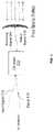
- FIG. 4Billustrates a block diagram of another exemplary centralized laser delivery system 451 according to examples of the disclosure.
- a single frequency modifier 454can be disposed before splitter 456 and modulators 452 A-E.
- Frequency modifier 454can receive a 1550 nm laser signal provided by a fiber-based laser source, and generate laser signal 463 having a wavelength of about 775-785 nm. In this configuration, modulation can still be performed on each laser signal provided to each individual LiDAR scanners, while reducing the number of required frequency modifiers.
- the splitter 456can be replaced with, for example, a configurable OADM, an optical switch, or an optical directional coupler that can be electrically controlled.
- the wavelength of a returned pulsemay be determined using various techniques.
- the detector of the LiDAR systemmay provide information regarding the wavelength of the returned pulse.
- LiDAR system 600includes a detector system using two detectors and one or more dichromatic optical elements, such as a filter or mirror, to determine the wavelength of a returned pulse.
- LiDAR system 600includes transmitter 1002 that transmits light pulse 1004 and 1006 , each having a different wavelength. These light pulses reflect off of object 1008 to produce light pulses 1010 and 1012 that travel back to LiDAR system 600 .
- Light pulse 1010travels through dichromatic element 1014 because dichromatic element 1014 has a high transmissivity for the wavelength of light pulse 1010 .
- a frequency modifierconfigured to:
- the light sourceincludes a first seed configured to produce a first seed pulse signal at the first wavelength and a second seed configured to produce a second pulse signal at the second wavelength.
Landscapes
- Engineering & Computer Science (AREA)
- Physics & Mathematics (AREA)
- Computer Networks & Wireless Communication (AREA)
- General Physics & Mathematics (AREA)
- Radar, Positioning & Navigation (AREA)
- Remote Sensing (AREA)
- Electromagnetism (AREA)
- Optical Radar Systems And Details Thereof (AREA)
- Optical Modulation, Optical Deflection, Nonlinear Optics, Optical Demodulation, Optical Logic Elements (AREA)
Abstract
Description
- receive a first laser signal emitted by a laser source, the first laser signal having a first wavelength, wherein the first wavelength is within the wavelength range detectable by a first plurality of LiDAR scanners and is outside a wavelength range detectable by a second plurality of LiDAR scanners;
- generate a second laser signal based on the first laser signal, the second laser signal having a second wavelength, wherein the second wavelength is outside a wavelength range detectable by the first plurality of LiDAR scanners and is within the wavelength range detectable by the second plurality of LiDAR scanners;
- a plurality of laser delivery channels, wherein each of the laser delivery channels being configured to deliver a corresponding third or fourth laser signal of the plurality of third or fourth laser signals to a respective LiDAR scanner of the plurality of LiDAR scanners.
- transmitting, using the light source, a first pulse signal at a first wavelength and a second pulse signal at a second wavelength different from the first wavelength, wherein the first pulse signal and the second pulse signal are transmitted concurrently or consecutively;
- detecting, using the light detector, a first returned pulse signal corresponding to the first pulse signal or the second pulse signal;
- determining based on the wavelength of the first returned pulse signal whether the returned pulse signal corresponds to the first pulse signal or the second pulse signal;
- in accordance with determining that the returned pulse signal corresponds to the first pulse signal, determining a first range based on timing of receiving the returned pulse signal and transmitting the first pulse signal; and
- in accordance with determining that the returned pulse signal corresponds to the second pulse signal, determining a second range based on timing of receiving the returned pulse signal and transmitting the second pulse signal.
Claims (14)
Priority Applications (2)
| Application Number | Priority Date | Filing Date | Title |
|---|---|---|---|
| US15/860,598US11300683B2 (en) | 2016-12-30 | 2018-01-02 | Multiwavelength LiDAR design |
| US17/533,018US11953601B2 (en) | 2016-12-30 | 2021-11-22 | Multiwavelength lidar design |
Applications Claiming Priority (3)
| Application Number | Priority Date | Filing Date | Title |
|---|---|---|---|
| US201662440818P | 2016-12-30 | 2016-12-30 | |
| US201762477740P | 2017-03-28 | 2017-03-28 | |
| US15/860,598US11300683B2 (en) | 2016-12-30 | 2018-01-02 | Multiwavelength LiDAR design |
Related Child Applications (1)
| Application Number | Title | Priority Date | Filing Date |
|---|---|---|---|
| US17/533,018ContinuationUS11953601B2 (en) | 2016-12-30 | 2021-11-22 | Multiwavelength lidar design |
Publications (2)
| Publication Number | Publication Date |
|---|---|
| US20180188371A1 US20180188371A1 (en) | 2018-07-05 |
| US11300683B2true US11300683B2 (en) | 2022-04-12 |
Family
ID=62711658
Family Applications (2)
| Application Number | Title | Priority Date | Filing Date |
|---|---|---|---|
| US15/860,598Active2039-04-21US11300683B2 (en) | 2016-12-30 | 2018-01-02 | Multiwavelength LiDAR design |
| US17/533,018ActiveUS11953601B2 (en) | 2016-12-30 | 2021-11-22 | Multiwavelength lidar design |
Family Applications After (1)
| Application Number | Title | Priority Date | Filing Date |
|---|---|---|---|
| US17/533,018ActiveUS11953601B2 (en) | 2016-12-30 | 2021-11-22 | Multiwavelength lidar design |
Country Status (6)
| Country | Link |
|---|---|
| US (2) | US11300683B2 (en) |
| EP (1) | EP3563180A4 (en) |
| JP (2) | JP7088937B2 (en) |
| KR (2) | KR102656372B1 (en) |
| CN (1) | CN110506220B (en) |
| WO (1) | WO2018182812A2 (en) |
Cited By (8)
| Publication number | Priority date | Publication date | Assignee | Title |
|---|---|---|---|---|
| US20200158830A1 (en)* | 2018-11-21 | 2020-05-21 | Silc Technologies, Inc. | Optical manifold for lidar applications |
| US20210109225A1 (en)* | 2019-10-10 | 2021-04-15 | GM Global Technology Operations LLC | High dynamic range lidar |
| US11914075B2 (en)* | 2018-07-24 | 2024-02-27 | Mitsubishi Electric Corporation | Distance measurement apparatus |
| US12339399B2 (en) | 2018-06-25 | 2025-06-24 | Silc Technologies, Inc. | Optical switching for tuning direction of LIDAR output signals |
| US12405378B2 (en) | 2019-06-28 | 2025-09-02 | Silc Technologies, Inc. | Use of frequency offsets in generation of LIDAR data |
| US12411213B2 (en) | 2021-10-11 | 2025-09-09 | Silc Technologies, Inc. | Separation of light signals in a LIDAR system |
| US12422618B2 (en) | 2022-10-13 | 2025-09-23 | Silc Technologies, Inc. | Buried taper with reflecting surface |
| US12429569B2 (en) | 2019-05-17 | 2025-09-30 | Silc Technologies, Inc. | Identification of materials illuminated by LIDAR systems |
Families Citing this family (76)
| Publication number | Priority date | Publication date | Assignee | Title |
|---|---|---|---|---|
| US11609336B1 (en) | 2018-08-21 | 2023-03-21 | Innovusion, Inc. | Refraction compensation for use in LiDAR systems |
| WO2018182812A2 (en) | 2016-12-30 | 2018-10-04 | Innovusion Ireland Limited | Multiwavelength lidar design |
| US10942257B2 (en) | 2016-12-31 | 2021-03-09 | Innovusion Ireland Limited | 2D scanning high precision LiDAR using combination of rotating concave mirror and beam steering devices |
| US10969475B2 (en) | 2017-01-05 | 2021-04-06 | Innovusion Ireland Limited | Method and system for encoding and decoding LiDAR |
| US11009605B2 (en) | 2017-01-05 | 2021-05-18 | Innovusion Ireland Limited | MEMS beam steering and fisheye receiving lens for LiDAR system |
| US11054508B2 (en) | 2017-01-05 | 2021-07-06 | Innovusion Ireland Limited | High resolution LiDAR using high frequency pulse firing |
| US10663595B2 (en)* | 2017-03-29 | 2020-05-26 | Luminar Technologies, Inc. | Synchronized multiple sensor head system for a vehicle |
| WO2018209606A1 (en)* | 2017-05-17 | 2018-11-22 | O-Net Communications (Shenzhen) Limited | Vehicle-mounted light detection and ranging (lidar) system |
| US10386856B2 (en) | 2017-06-29 | 2019-08-20 | Uber Technologies, Inc. | Autonomous vehicle collision mitigation systems and methods |
| US10065638B1 (en) | 2017-08-03 | 2018-09-04 | Uber Technologies, Inc. | Multi-model switching on a collision mitigation system |
| CN111542765B (en) | 2017-10-19 | 2024-08-02 | 图达通智能美国有限公司 | LIDAR with large dynamic range |
| US11493601B2 (en) | 2017-12-22 | 2022-11-08 | Innovusion, Inc. | High density LIDAR scanning |
| US11675050B2 (en) | 2018-01-09 | 2023-06-13 | Innovusion, Inc. | LiDAR detection systems and methods |
| US11977184B2 (en) | 2018-01-09 | 2024-05-07 | Seyond, Inc. | LiDAR detection systems and methods that use multi-plane mirrors |
| WO2019164961A1 (en) | 2018-02-21 | 2019-08-29 | Innovusion Ireland Limited | Lidar systems with fiber optic coupling |
| US11391823B2 (en) | 2018-02-21 | 2022-07-19 | Innovusion, Inc. | LiDAR detection systems and methods with high repetition rate to observe far objects |
| WO2019165289A1 (en) | 2018-02-22 | 2019-08-29 | Innovusion Ireland Limited | Receive path for lidar system |
| US11808888B2 (en) | 2018-02-23 | 2023-11-07 | Innovusion, Inc. | Multi-wavelength pulse steering in LiDAR systems |
| US12085673B2 (en) | 2018-02-23 | 2024-09-10 | Seyond, Inc. | Distributed LiDAR systems |
| WO2019165294A1 (en) | 2018-02-23 | 2019-08-29 | Innovusion Ireland Limited | 2-dimensional steering system for lidar systems |
| WO2019245614A2 (en) | 2018-03-09 | 2019-12-26 | Innovusion Ireland Limited | Lidar safety systems and methods |
| US11789132B2 (en) | 2018-04-09 | 2023-10-17 | Innovusion, Inc. | Compensation circuitry for lidar receiver systems and method of use thereof |
| WO2019199775A1 (en) | 2018-04-09 | 2019-10-17 | Innovusion Ireland Limited | Lidar systems and methods for exercising precise control of a fiber laser |
| CN112585492B (en) | 2018-06-15 | 2024-10-25 | 图达通智能美国有限公司 | LIDAR system and method for focusing a range of interest |
| US10754011B2 (en)* | 2018-06-29 | 2020-08-25 | Perceptive Inc. | Perception systems for use in autonomously controlling systems |
| US11579300B1 (en) | 2018-08-21 | 2023-02-14 | Innovusion, Inc. | Dual lens receive path for LiDAR system |
| US11860316B1 (en) | 2018-08-21 | 2024-01-02 | Innovusion, Inc. | Systems and method for debris and water obfuscation compensation for use in LiDAR systems |
| US11796645B1 (en) | 2018-08-24 | 2023-10-24 | Innovusion, Inc. | Systems and methods for tuning filters for use in lidar systems |
| US11614526B1 (en) | 2018-08-24 | 2023-03-28 | Innovusion, Inc. | Virtual windows for LIDAR safety systems and methods |
| US11579258B1 (en) | 2018-08-30 | 2023-02-14 | Innovusion, Inc. | Solid state pulse steering in lidar systems |
| US12313788B1 (en) | 2018-10-09 | 2025-05-27 | Seyond, Inc. | Ultrashort pulses in LiDAR systems |
| US11059478B2 (en)* | 2018-10-10 | 2021-07-13 | GM Global Technology Operations LLC | System and method for autonomous control of a vehicle |
| WO2020102406A1 (en) | 2018-11-14 | 2020-05-22 | Innovusion Ireland Limited | Lidar systems and methods that use a multi-facet mirror |
| DE102018129246B4 (en)* | 2018-11-21 | 2020-10-15 | Infineon Technologies Ag | INTERFERENCE DETECTION AND REDUCTION FOR LIDAR SYSTEMS |
| JP2022510198A (en) | 2018-11-29 | 2022-01-26 | エスゼット ディージェイアイ テクノロジー カンパニー リミテッド | A system for detecting the environment around a mobile platform and its method |
| US10401480B1 (en)* | 2018-12-05 | 2019-09-03 | Luminar Technologies, Inc. | Lidar receiver with multiple detectors for range-ambiguity mitigation |
| US10931374B1 (en) | 2018-12-13 | 2021-02-23 | Waymo Llc | Vehicle with free-space optical link for log data uploading |
| US11675055B2 (en) | 2019-01-10 | 2023-06-13 | Innovusion, Inc. | LiDAR systems and methods with beam steering and wide angle signal detection |
| US11486970B1 (en) | 2019-02-11 | 2022-11-01 | Innovusion, Inc. | Multiple beam generation from a single source beam for use with a LiDAR system |
| US11977185B1 (en) | 2019-04-04 | 2024-05-07 | Seyond, Inc. | Variable angle polygon for use with a LiDAR system |
| US11482828B2 (en)* | 2019-06-28 | 2022-10-25 | Thomas James Kane | Passively Q-switched laser and laser system for ranging applications |
| KR20210003003A (en)* | 2019-07-01 | 2021-01-11 | 삼성전자주식회사 | Lidar apparatus and controlling method thereof |
| CN210390983U (en)* | 2019-08-15 | 2020-04-24 | 北京百度网讯科技有限公司 | autonomous vehicle |
| US11899139B2 (en)* | 2019-09-20 | 2024-02-13 | Intel Corporation | Photonic devices with redundant components and their applications |
| US11550043B2 (en) | 2020-01-13 | 2023-01-10 | Samsung Electronics Co., Ltd. | Spatially and temporally coherent multi-LiDAR point cloud fusion |
| US10901074B1 (en) | 2020-02-17 | 2021-01-26 | Hesai Technology Co., Ltd. | Systems and methods for improving Lidar performance |
| CN113267762A (en)* | 2020-02-17 | 2021-08-17 | 上海禾赛科技有限公司 | Laser radar |
| CN112654884B (en)* | 2020-03-13 | 2022-03-08 | 华为技术有限公司 | Radar system, signal processing method and device |
| CN111458724B (en)* | 2020-04-23 | 2024-11-22 | 深圳煜炜光学科技有限公司 | A laser radar point cloud imaging device and method suitable for autonomous driving |
| US11561289B2 (en)* | 2020-09-25 | 2023-01-24 | Beijing Voyager Technology Co., Ltd. | Scanning LiDAR system with a wedge prism |
| US12017678B2 (en) | 2020-10-09 | 2024-06-25 | Direct Cursus Technology L.L.C | Multispectral LIDAR systems and methods |
| CN112455353A (en)* | 2021-01-07 | 2021-03-09 | 蔚来汽车科技(安徽)有限公司 | Support, support assembly, roof device and vehicle |
| US12061289B2 (en) | 2021-02-16 | 2024-08-13 | Innovusion, Inc. | Attaching a glass mirror to a rotating metal motor frame |
| US11422267B1 (en) | 2021-02-18 | 2022-08-23 | Innovusion, Inc. | Dual shaft axial flux motor for optical scanners |
| US11789128B2 (en) | 2021-03-01 | 2023-10-17 | Innovusion, Inc. | Fiber-based transmitter and receiver channels of light detection and ranging systems |
| US11555895B2 (en) | 2021-04-20 | 2023-01-17 | Innovusion, Inc. | Dynamic compensation to polygon and motor tolerance using galvo control profile |
| US11614521B2 (en) | 2021-04-21 | 2023-03-28 | Innovusion, Inc. | LiDAR scanner with pivot prism and mirror |
| WO2022225859A1 (en) | 2021-04-22 | 2022-10-27 | Innovusion, Inc. | A compact lidar design with high resolution and ultra-wide field of view |
| CN117178199A (en) | 2021-04-22 | 2023-12-05 | 图达通智能美国有限公司 | Compact light detection and ranging design with high resolution and ultra wide field of view |
| EP4314885A1 (en) | 2021-05-12 | 2024-02-07 | Innovusion, Inc. | Systems and apparatuses for mitigating lidar noise, vibration, and harshness |
| EP4314884A1 (en) | 2021-05-21 | 2024-02-07 | Innovusion, Inc. | Movement profiles for smart scanning using galvonometer mirror inside lidar scanner |
| US20220404470A1 (en)* | 2021-06-17 | 2022-12-22 | Silc Technologies, Inc. | Scanning multiple lidar system output signals |
| US11768294B2 (en) | 2021-07-09 | 2023-09-26 | Innovusion, Inc. | Compact lidar systems for vehicle contour fitting |
| DE102021120807A1 (en) | 2021-08-10 | 2023-02-16 | OSRAM Opto Semiconductors Gesellschaft mit beschränkter Haftung | LIDAR SENSING DEVICE AND MEASUREMENT METHOD |
| CN216356147U (en) | 2021-11-24 | 2022-04-19 | 图达通智能科技(苏州)有限公司 | Vehicle-mounted laser radar motor, vehicle-mounted laser radar and vehicle |
| US20230221415A1 (en)* | 2022-01-07 | 2023-07-13 | Aeye, Inc. | Systems and methods of multispectral scanning lidar |
| US11982748B2 (en) | 2022-01-20 | 2024-05-14 | Silc Technologies, Inc. | Imaging system having multiple cores |
| US12066541B2 (en) | 2022-01-20 | 2024-08-20 | Silc Technologies, Inc. | Imaging system having multiple cores |
| US11871130B2 (en) | 2022-03-25 | 2024-01-09 | Innovusion, Inc. | Compact perception device |
| US12204033B2 (en) | 2022-03-25 | 2025-01-21 | Seyond, Inc. | Multimodal detection with integrated sensors |
| CN116106932B (en)* | 2023-04-13 | 2023-06-27 | 深圳煜炜光学科技有限公司 | Vehicle-mounted laser radar device and control method thereof |
| DE102023110581B3 (en) | 2023-04-25 | 2024-07-04 | Deutsches Zentrum für Luft- und Raumfahrt e.V. | Optical measuring system for recording environmental parameters in an environment |
| WO2025155346A2 (en)* | 2023-08-21 | 2025-07-24 | Seyond, Inc. | Laser trigger patterns to reduce noise and isolate signal origin |
| US11965982B1 (en)* | 2023-10-11 | 2024-04-23 | Aurora Operations, Inc. | LIDAR sensor system including integrated transceiver |
| WO2025111120A1 (en)* | 2023-11-22 | 2025-05-30 | Aurora Operations, Inc. | Lidar sensor system including particular optic design |
| US12422524B2 (en) | 2023-11-22 | 2025-09-23 | Aurora Operations, Inc. | LIDAR sensor system including particular optic design |
Citations (134)
| Publication number | Priority date | Publication date | Assignee | Title |
|---|---|---|---|---|
| GB2000411A (en) | 1977-06-15 | 1979-01-04 | Impulsphysik Gmbh | Ceilometric method and apparatus |
| US5006721A (en) | 1990-03-23 | 1991-04-09 | Perceptron, Inc. | Lidar scanning system |
| US5157451A (en) | 1991-04-01 | 1992-10-20 | John Taboada | Laser imaging and ranging system using two cameras |
| US5442358A (en) | 1991-08-16 | 1995-08-15 | Kaman Aerospace Corporation | Imaging lidar transmitter downlink for command guidance of underwater vehicle |
| US5546188A (en) | 1992-11-23 | 1996-08-13 | Schwartz Electro-Optics, Inc. | Intelligent vehicle highway system sensor and method |
| US5579153A (en) | 1992-04-27 | 1996-11-26 | Pirelli Cavi S.P.A. | Optical power limiting amplifier |
| US5657077A (en) | 1993-02-18 | 1997-08-12 | Deangelis; Douglas J. | Event recording system with digital line camera |
| US5793491A (en) | 1992-12-30 | 1998-08-11 | Schwartz Electro-Optics, Inc. | Intelligent vehicle highway system multi-lane sensor and method |
| US5838239A (en) | 1992-10-20 | 1998-11-17 | Robotic Vision Systems, Inc. | System for detecting ice or snow on surface which specularly reflects light |
| US5926259A (en) | 1995-05-04 | 1999-07-20 | Bushnell Corporation | Laser range finder with target quality display |
| US6163378A (en) | 1999-06-14 | 2000-12-19 | Khoury; Jehad | Spectroscopic time integrative correlation for rapid medical diagnostic and universal image analysis |
| US6317202B1 (en) | 1998-11-12 | 2001-11-13 | Denso Corporation | Automotive radar detecting lane mark and frontal obstacle |
| JP2002221574A (en) | 2001-01-25 | 2002-08-09 | Mitsubishi Heavy Ind Ltd | Method and system for identifying aerial position of flying object |
| EP1237305A2 (en) | 2001-02-28 | 2002-09-04 | KiloLambda IP Limited | Multi-wavelength light source |
| US20020136251A1 (en) | 2001-01-25 | 2002-09-26 | Science And Technology Corporation | Automatic gain control system for use with multiple wavelength signal detector |
| US6593582B2 (en) | 2001-05-11 | 2003-07-15 | Science & Engineering Services, Inc. | Portable digital lidar system |
| US6650404B1 (en) | 2002-05-28 | 2003-11-18 | Analog Modules, Inc. | Laser rangefinder receiver |
| US20040135992A1 (en) | 2002-11-26 | 2004-07-15 | Munro James F. | Apparatus for high accuracy distance and velocity measurement and methods thereof |
| JP2005009956A (en) | 2003-06-18 | 2005-01-13 | Mitsubishi Electric Corp | Laser equipment |
| US20050033497A1 (en)* | 2003-08-06 | 2005-02-10 | Stopczynski Lawrence Gerard | Method of controlling an external object sensor for an automotive vehicle |
| US20050190424A1 (en) | 2004-02-27 | 2005-09-01 | Sick Ag | Method and device for optical scanning of objects |
| US20060071846A1 (en)* | 2003-05-30 | 2006-04-06 | Yakayuki Yanagisawa | Coherent laser radar |
| US20060132752A1 (en) | 2004-12-16 | 2006-06-22 | Kane David M | Micromechanical and related lidar apparatus and method, and fast light-routing components |
| US7128267B2 (en) | 2003-07-11 | 2006-10-31 | Sick Ag | Device for optical scanning of objects, especially markings |
| US7209221B2 (en) | 1994-05-23 | 2007-04-24 | Automotive Technologies International, Inc. | Method for obtaining and displaying information about objects in a vehicular blind spot |
| US20070091948A1 (en) | 2005-07-29 | 2007-04-26 | Aculight Corporation | Multi-stage optical amplifier having photonic-crystal waveguides for generation of high-power pulsed radiation and associated method |
| JP2007144667A (en) | 2005-11-24 | 2007-06-14 | Fuji Xerox Co Ltd | Image forming apparatus and formed image correcting method |
| US7345271B2 (en) | 2002-09-25 | 2008-03-18 | Ibeo Automobile Sensor Gmbh | Optoelectric sensing device with common deflection device |
| EP1923721A1 (en) | 2005-08-15 | 2008-05-21 | Topcon Corporation | Measuring device |
| US20080174762A1 (en) | 2006-08-29 | 2008-07-24 | Jony Jiang Liu | Micro-mirror optical tracking and ranging system |
| US20090010644A1 (en) | 2002-02-01 | 2009-01-08 | Cubic Corporation | Integrated optical communication and range finding system and applications thereof |
| US20090051926A1 (en) | 2007-04-13 | 2009-02-26 | United States Of America As Represented By The Administrator Of The National Aeronautics And Spac | Multiple frequency optical mixer and demultiplexer and apparatus for remote sensing |
| US20090059201A1 (en) | 2007-08-28 | 2009-03-05 | Science Applications International Corporation | Full-Field Light Detection and Ranging Imaging System |
| US20090147239A1 (en)* | 2005-09-02 | 2009-06-11 | Neptec | Apparatus and method for tracking an object |
| US20090262760A1 (en) | 2005-01-20 | 2009-10-22 | Vladimir Krupkin | Laser Obstacle Ranging and Display |
| US20100006760A1 (en) | 2004-04-13 | 2010-01-14 | Science & Engineering Services, Inc. | Ultraviolet lidar for detection of biological warfare agents |
| US7649616B2 (en) | 2004-07-08 | 2010-01-19 | Lockheed Martin Corporation | Fiber laser ladar |
| US20100020306A1 (en) | 2006-07-13 | 2010-01-28 | Velodyne Acoustics, Inc. | High definition lidar system |
| US20100027602A1 (en) | 2008-07-31 | 2010-02-04 | United States Of America As Represented By The Administrator Of The National Aeronautics And Spac | Time delay and distance measurement |
| JP2010035385A (en) | 2008-07-31 | 2010-02-12 | Kyocera Mita Corp | Motor drive controller |
| EP2157445A2 (en) | 2008-08-19 | 2010-02-24 | Rosemount Aerospace Inc. | Lidar system using a pseudo-random pulse sequence |
| JP2010085316A (en) | 2008-10-01 | 2010-04-15 | Topcon Corp | Laser apparatus and distance measuring device |
| US7724423B2 (en) | 2006-03-16 | 2010-05-25 | Alcatel-Lucent Usa Inc. | Optical fiber laser having improved efficiency |
| US20100128109A1 (en) | 2008-11-25 | 2010-05-27 | Banks Paul S | Systems And Methods Of High Resolution Three-Dimensional Imaging |
| US20100271614A1 (en) | 2006-01-27 | 2010-10-28 | Vijay Albuquerque | LIDAR system utilizing SOI-based opto-electronic components |
| US7880865B2 (en) | 2007-02-28 | 2011-02-01 | Denso Wave Incorporated | Laser radar apparatus for three-dimensional detection of objects |
| EP2395368A1 (en) | 2010-06-11 | 2011-12-14 | Sick AG | Distance-measuring laser scanner for detecting objects in a surveillance range |
| US20120038903A1 (en) | 2010-08-16 | 2012-02-16 | Ball Aerospace & Technologies Corp. | Electronically steered flash lidar |
| US20120124113A1 (en) | 2010-11-05 | 2012-05-17 | University of Maribor | LIGHT DETECTION AND RANGING (LiDAR)DATA COMPRESSION AND DECOMPRESSION METHODS AND APPARATUS |
| US20120221142A1 (en) | 2011-02-24 | 2012-08-30 | Mss, Inc. | Sequential Scanning Of Multiple Wavelengths |
| US8270440B2 (en) | 2005-04-07 | 2012-09-18 | Panasonic Corporation | Laser light source and optical device |
| US20130107016A1 (en) | 2010-05-17 | 2013-05-02 | Iee International Electronics & Engineering S.A. | Scanning 3d imager |
| KR20130068224A (en) | 2011-12-15 | 2013-06-26 | 여우순엽 | The apparatus and method of monitoring with terrestrial lidar and reflectless totalstation |
| US20130293867A1 (en) | 2009-09-23 | 2013-11-07 | Pixart Imaging Inc. | Distance-measuring device of measuring distance according to variation of imaging location and calibrating method thereof |
| US20130293946A1 (en)* | 2012-05-01 | 2013-11-07 | Imra America, Inc. | Optical frequency ruler |
| US20140078514A1 (en) | 2010-10-22 | 2014-03-20 | Neptec Design Group Ltd. | Wide angle bistatic scanning optical ranging sensor |
| US20140347650A1 (en) | 2011-12-23 | 2014-11-27 | Leica Geosystems Ag | Distance-measuring device alignment |
| US20140350836A1 (en)* | 2013-05-24 | 2014-11-27 | Advance Scientific Concepts, Inc. | Automotive auxiliary ladar sensor |
| WO2014203654A1 (en) | 2013-06-17 | 2014-12-24 | 株式会社日立製作所 | Distance measurement device, shape measurement device, processing system, distance measurement method, shape measurement method, and processing method |
| US20150078123A1 (en) | 2013-09-16 | 2015-03-19 | Appareo Systems, Llc | Synthetic underwater visualization system |
| US20150084805A1 (en) | 2012-03-19 | 2015-03-26 | Qinetiq Limited | Detection Techniques |
| US8994928B2 (en) | 2011-03-02 | 2015-03-31 | Toyota Jidosha Kabushiki Kaisha | Laser radar device |
| US20150116692A1 (en) | 2012-04-30 | 2015-04-30 | Michigan Aerospace Corporation | System and method for scan range gating |
| US20150139259A1 (en) | 2013-11-21 | 2015-05-21 | Christie Digital Systems Canada Inc. | Method, system and apparatus for automatically determining operating conditions of a periodically poled lithium niobate crystal in a laser system |
| EP2889642A1 (en) | 2013-12-16 | 2015-07-01 | Riegl Laser Measurement Systems GmbH | Method for distance measurement |
| US9086273B1 (en)* | 2013-03-08 | 2015-07-21 | Google Inc. | Microrod compression of laser beam in combination with transmit lens |
| US20150355327A1 (en) | 2012-11-21 | 2015-12-10 | Nikon Metrology Nv | Scan mirrors for laser radar |
| US20160003946A1 (en) | 2014-07-03 | 2016-01-07 | Advanced Scientific Concepts, Inc. | Ladar sensor for a dense environment |
| US20160047900A1 (en) | 2014-08-15 | 2016-02-18 | US LADAR, Inc. | Method and System for Scanning Ladar Transmission with Pulse Modulation |
| US20160061935A1 (en)* | 2014-08-28 | 2016-03-03 | Google Inc. | Methods and Systems for Vehicle Radar Coordination and Interference Reduction |
| US20160061655A1 (en)* | 2014-09-03 | 2016-03-03 | Panasonic Intellectual Property Management Co., Ltd. | Measurement system |
| US9279662B2 (en) | 2012-09-14 | 2016-03-08 | Faro Technologies, Inc. | Laser scanner |
| US9304316B2 (en) | 2004-11-15 | 2016-04-05 | Apple Inc. | Method and device for scanning light |
| US20160100521A1 (en)* | 2014-10-10 | 2016-04-14 | Irobot Corporation | Autonomous Robot Localization |
| US9316724B2 (en) | 2012-12-18 | 2016-04-19 | Sick Ag | Optoelectronic sensor for the detection of objects |
| US20160117048A1 (en) | 2014-09-26 | 2016-04-28 | Cypress Semiconductor Corporation | Background Light Detection for Optical Navigation Systems |
| US20160245902A1 (en) | 2015-02-25 | 2016-08-25 | Abbie T. Watnik | Real-time processing and adaptable illumination lidar camera using a spatial light modulator |
| US20160291134A1 (en) | 2015-04-06 | 2016-10-06 | Google Inc. | Long Range Steerable LIDAR System |
| US20160313445A1 (en) | 2012-03-16 | 2016-10-27 | Advanced Scientific Concepts, Inc. | Personal ladar sensor |
| US20160327646A1 (en) | 2015-05-07 | 2016-11-10 | GM Global Technology Operations LLC | Pseudo random sequences in array lidar systems |
| US9515451B2 (en) | 2015-01-29 | 2016-12-06 | Massachusetts Institute Of Technology | Systems and methods for light amplification |
| US9541377B1 (en) | 2015-06-30 | 2017-01-10 | Korea Research Institute Of Standards And Science | Apparatus for real-time non-contact non-destructive thickness measurement using terahertz wave |
| US20170153319A1 (en)* | 2015-11-30 | 2017-06-01 | Luminar Technologies, Inc. | Lidar system with distributed laser and multiple sensor heads |
| US9680280B2 (en) | 2004-03-31 | 2017-06-13 | Imra America, Inc. | Method and apparatus for controlling and protecting pulsed high power fiber amplifier systems |
| JP2017138301A (en) | 2016-01-28 | 2017-08-10 | 株式会社デンソー | Laser radar equipment |
| US9755397B2 (en) | 2014-12-12 | 2017-09-05 | Omron Corporation | Light amplifying device and laser processing apparatus |
| US20170365105A1 (en) | 2016-06-17 | 2017-12-21 | Ford Global Technologies, Llc | Method and apparatus for inter-vehicular safety awareness and alert |
| US9869754B1 (en) | 2017-03-22 | 2018-01-16 | Luminar Technologies, Inc. | Scan patterns for lidar systems |
| US9940761B2 (en) | 2016-08-02 | 2018-04-10 | International Business Machines Corporation | Self-driving vehicle sensor fault remediation |
| US20180158471A1 (en) | 2016-12-02 | 2018-06-07 | Breakaway Records, L.L.C. | Record Stabilizer for Multiple Vinyl Sizes |
| US20180188358A1 (en) | 2017-01-05 | 2018-07-05 | Innovusion Ireland Limited | METHOD AND SYSTEM FOR ENCODING AND DECODING LiDAR |
| US20180188371A1 (en) | 2016-12-30 | 2018-07-05 | Innovusion Ireland Limited | Multiwavelength lidar design |
| US20180188355A1 (en) | 2016-12-31 | 2018-07-05 | Innovusion Ireland Limited | 2D SCANNING HIGH PRECISION LiDAR USING COMBINATION OF ROTATING CONCAVE MIRROR AND BEAM STEERING DEVICES |
| US20180188357A1 (en) | 2017-01-05 | 2018-07-05 | Innovusion Ireland Limited | HIGH RESOLUTION LiDAR USING HIGH FREQUENCY PULSE FIRING |
| WO2018129410A1 (en) | 2017-01-05 | 2018-07-12 | Innovusion Ireland Limited | Mems beam steering and fisheye receiving lens for lidar system |
| US20180210084A1 (en) | 2017-01-26 | 2018-07-26 | Sick Ag | Optoelectronic sensor and method of determining the distance of an object in a monitored zone |
| US10042159B2 (en) | 2016-02-18 | 2018-08-07 | Aeye, Inc. | Ladar transmitter with optical field splitter/inverter |
| US10061019B1 (en) | 2017-03-28 | 2018-08-28 | Luminar Technologies, Inc. | Diffractive optical element in a lidar system to correct for backscan |
| WO2018175990A1 (en) | 2017-03-23 | 2018-09-27 | Innovusion Ireland Limited | High resolution lidar using multi-stage multi-phase signal modulation, integration, sampling, and analysis |
| KR20180107673A (en) | 2017-03-22 | 2018-10-02 | (주) 위키옵틱스 | LIDAR light-emitting system improved pattern rotation |
| US10094925B1 (en) | 2017-03-31 | 2018-10-09 | Luminar Technologies, Inc. | Multispectral lidar system |
| US20180329060A1 (en) | 2017-05-15 | 2018-11-15 | Ouster, Inc. | Lidar unit with an optical link between controller and photosensor layer |
| US10137903B2 (en) | 2016-08-16 | 2018-11-27 | Uber Technologies, Inc. | Autonomous vehicle diagnostic system |
| US20180359460A1 (en) | 2015-09-24 | 2018-12-13 | Ouster, Inc. | Optical imaging system with a plurality of sense channels |
| US10191155B2 (en) | 2017-03-29 | 2019-01-29 | Luminar Technologies, Inc. | Optical resolution in front of a vehicle |
| US20190107623A1 (en) | 2017-10-09 | 2019-04-11 | Luminar Technologies, Inc. | Adjustable scan patterns for lidar system |
| US20190120962A1 (en) | 2017-10-20 | 2019-04-25 | Sick Ag | Transmission/reception module for an optoelectronic sensor and method of detecting objects |
| WO2019079642A1 (en) | 2017-10-19 | 2019-04-25 | Innovusion Ireland Limited | Lidar with large dynamic range |
| US10295656B1 (en) | 2018-06-13 | 2019-05-21 | Hesai Photonics Technology Co., Ltd. | Lidar systems and methods |
| US20190154804A1 (en) | 2017-11-22 | 2019-05-23 | Luminar Technologies, Inc. | Efficient orientation of a lidar system in a vehicle |
| US20190154807A1 (en) | 2017-11-21 | 2019-05-23 | Sick Ag | Polygon scanner and method of detecting objects in a monitored zone |
| US10324170B1 (en) | 2018-04-05 | 2019-06-18 | Luminar Technologies, Inc. | Multi-beam lidar system with polygon mirror |
| US20190257924A1 (en) | 2018-02-22 | 2019-08-22 | Innovusion Ireland Limited | Receive path for lidar system |
| US10393877B2 (en) | 2016-06-01 | 2019-08-27 | Velodyne Lidar, Inc. | Multiple pixel scanning LIDAR |
| US20190265339A1 (en) | 2018-02-23 | 2019-08-29 | Innovusion Ireland Limited | Distributed lidar systems |
| US20190265336A1 (en) | 2018-02-23 | 2019-08-29 | Innovusion Ireland Limited | 2-dimensional steering system for lidar systems |
| US20190265337A1 (en) | 2018-02-23 | 2019-08-29 | Innovusion Ireland Limited | Multi-wavelength pulse steering in lidar systems |
| US20190277952A1 (en) | 2018-03-08 | 2019-09-12 | Zf Friedrichshafen Ag | Receiver arrangement for the reception of light impulses, lidar module and method for receiving light impulses |
| US10429495B1 (en) | 2018-04-03 | 2019-10-01 | Hesai Photonics Technology Co., Ltd. | Lidar system and method |
| US10451716B2 (en) | 2017-11-22 | 2019-10-22 | Luminar Technologies, Inc. | Monitoring rotation of a mirror in a lidar system |
| US10627491B2 (en) | 2017-03-31 | 2020-04-21 | Velodyne Lidar, Inc. | Integrated LIDAR illumination power control |
| US10641872B2 (en) | 2016-02-18 | 2020-05-05 | Aeye, Inc. | Ladar receiver with advanced optics |
| US10663596B2 (en) | 2017-09-15 | 2020-05-26 | Aeye, Inc. | Ladar receiver with co-bore sited camera |
| US10663564B2 (en) | 2017-03-30 | 2020-05-26 | Luminar Technologies, Inc. | Cross-talk mitigation using wavelength switching |
| US10684360B2 (en) | 2017-03-30 | 2020-06-16 | Luminar Technologies, Inc. | Protecting detector in a lidar system using off-axis illumination |
| US20200227882A1 (en) | 2018-04-09 | 2020-07-16 | Innovusion Ireland Limited | Lidar systems and methods for exercising precise control of a fiber laser |
| US20200256964A1 (en) | 2017-03-29 | 2020-08-13 | Luminar Technologies, Inc. | Sizing the field of view of a detector to improve operation of a lidar system |
| US20200319310A1 (en) | 2016-01-31 | 2020-10-08 | Velodyne Lidar, Inc. | Multiple pulse, lidar based 3-d imaging |
| US20200400798A1 (en) | 2019-06-21 | 2020-12-24 | Aeva, Inc. | Lidar system with solid state spectral scanning |
| US10908262B2 (en) | 2016-02-18 | 2021-02-02 | Aeye, Inc. | Ladar transmitter with optical field splitter/inverter for improved gaze on scan area portions |
| US20210088630A9 (en) | 2017-04-19 | 2021-03-25 | Surestar Laser Technology (Suzhou) Co., Ltd. | Laser scanning device, radar device and scanning method thereof |
| US11002835B2 (en) | 2018-04-03 | 2021-05-11 | Hesai Photonics Technology Co., Ltd. | Distributed laser radar |
| US11022688B2 (en) | 2017-03-31 | 2021-06-01 | Luminar, Llc | Multi-eye lidar system |
| US11029406B2 (en) | 2018-04-06 | 2021-06-08 | Luminar, Llc | Lidar system with AlInAsSb avalanche photodiode |
Family Cites Families (139)
| Publication number | Priority date | Publication date | Assignee | Title |
|---|---|---|---|---|
| JPS5245479B2 (en) | 1972-02-19 | 1977-11-16 | ||
| US3897150A (en) | 1972-04-03 | 1975-07-29 | Hughes Aircraft Co | Scanned laser imaging and ranging system |
| US4464048A (en) | 1981-03-25 | 1984-08-07 | Barr & Stroud Limited | Laser rangefinders |
| US4676586A (en) | 1982-12-20 | 1987-06-30 | General Electric Company | Apparatus and method for performing laser material processing through a fiber optic |
| DE3524858A1 (en) | 1985-07-12 | 1987-01-22 | Leybold Heraeus Gmbh & Co Kg | ARRANGEMENT FOR CONTROLLING THE TILTING PROCESS OF A MELTING POT |
| US5185736A (en) | 1989-05-12 | 1993-02-09 | Alcatel Na Network Systems Corp. | Synchronous optical transmission system |
| US5012079A (en) | 1989-11-13 | 1991-04-30 | Lazerdata Corporation | Bar code scanner mirror assembly |
| US5173797A (en) | 1990-05-08 | 1992-12-22 | Xerox Corporation | Rotating mirror optical scanner with grooved grease bearings |
| JPH04255280A (en) | 1991-02-07 | 1992-09-10 | Nippon Steel Corp | Semiconductor laser excitation solid-state laser device |
| US5254893A (en) | 1992-01-30 | 1993-10-19 | Ide Russell D | Shaft support assembly for use in a polygon mirror drive motor |
| US5504731A (en) | 1992-03-06 | 1996-04-02 | Quantum Corporation | Remote fine positioning mechanism |
| US5319434A (en) | 1992-12-30 | 1994-06-07 | Litton Systems, Inc. | Laser rangefinder apparatus with fiber optic interface |
| US5691808A (en) | 1995-07-31 | 1997-11-25 | Hughes Electronics | Laser range finder receiver |
| US5936756A (en) | 1996-01-10 | 1999-08-10 | Ricoh Company Ltd. | Compact scanning optical system |
| JP3446466B2 (en) | 1996-04-04 | 2003-09-16 | 株式会社デンソー | Reflection measuring device for inter-vehicle distance control device and inter-vehicle distance control device using the same |
| JPH09297014A (en)* | 1996-05-08 | 1997-11-18 | Mitsubishi Heavy Ind Ltd | Laser radar 3-d form measurement device |
| US5920140A (en) | 1997-06-27 | 1999-07-06 | Asahi Kogaku Kogyo Kabushiki Kaisha | Galvano mirror unit |
| US20020149757A1 (en) | 2001-02-28 | 2002-10-17 | Optical Switch Corporation | Polarization vector alignment for interference lithography patterning |
| AUPR558501A0 (en)* | 2001-06-12 | 2001-07-12 | Citech Sports Corporation Pty Ltd | System and method for monitoring and displaying athlete char acteristics |
| AU2004206520A1 (en)* | 2003-01-15 | 2004-08-05 | Arete Associates | Ultraviolet, infrared, and near-infrared lidar system and method |
| US6822742B1 (en)* | 2003-12-19 | 2004-11-23 | Eastman Kodak Company | System and method for remote quantitative detection of fluid leaks from a natural gas or oil pipeline |
| JP2005291787A (en) | 2004-03-31 | 2005-10-20 | Denso Corp | Distance detection device |
| US7436492B2 (en) | 2004-04-02 | 2008-10-14 | Leica Geosystems Ag | Electronic distance meter featuring spectral and spatial selectivity |
| US7511824B2 (en)* | 2005-02-14 | 2009-03-31 | Digital Signal Corporation | Chirped coherent laser radar system and method |
| US8190030B2 (en)* | 2005-11-10 | 2012-05-29 | Optical Air Data Systems, Llc | Single aperture multiple optical waveguide transceiver |
| US7519253B2 (en) | 2005-11-18 | 2009-04-14 | Omni Sciences, Inc. | Broadband or mid-infrared fiber light sources |
| US7944548B2 (en)* | 2006-03-07 | 2011-05-17 | Leica Geosystems Ag | Increasing measurement rate in time of flight measurement apparatuses |
| US7502395B2 (en)* | 2006-08-08 | 2009-03-10 | Northrop Grumman Space & Mission Systems Corp. | Pulsed coherent fiber array and method |
| US7701558B2 (en)* | 2006-09-22 | 2010-04-20 | Leica Geosystems Ag | LIDAR system |
| EP2078212A4 (en) | 2006-10-30 | 2010-12-29 | Autonosys Inc | Scanning system for lidar |
| WO2008101120A1 (en) | 2007-02-14 | 2008-08-21 | Finisar Corporation | Collimated ball lenses for optical triplexers |
| US7639347B2 (en)* | 2007-02-14 | 2009-12-29 | Leica Geosystems Ag | High-speed laser ranging system including a fiber laser |
| CN101201403A (en)* | 2007-04-27 | 2008-06-18 | 北京航空航天大学 | 3D Polarization Imaging LiDAR Remote Sensor |
| US8200112B2 (en) | 2007-11-30 | 2012-06-12 | Lexmark International, Inc. | Fuser assembly heater setpoint control |
| DE102008031681A1 (en)* | 2008-07-04 | 2010-01-14 | Eads Deutschland Gmbh | LIDAR method for measuring velocities and LIDAR device with timed detection |
| US7869112B2 (en) | 2008-07-25 | 2011-01-11 | Prysm, Inc. | Beam scanning based on two-dimensional polygon scanner for display and other applications |
| US8757064B2 (en) | 2008-08-08 | 2014-06-24 | Mbda Uk Limited | Optical proximity fuze |
| US8687173B2 (en) | 2008-09-11 | 2014-04-01 | Nikon Metrology N.V. | Compact fiber optic geometry for a counter chirp FMCW coherent laser radar |
| KR100993625B1 (en)* | 2009-02-25 | 2010-11-11 | (주)하드램 | Laser Direct Imaging System with Multi Scanner Unit |
| EP2449637B1 (en) | 2009-06-30 | 2013-04-10 | Trimble AB | Optical pulse transmitter |
| US8125622B2 (en) | 2009-07-28 | 2012-02-28 | Applied Concepts, Inc. | Lidar measurement device with target tracking and method for use of same |
| US8169596B2 (en)* | 2009-08-17 | 2012-05-01 | Seegrid Corporation | System and method using a multi-plane curtain |
| US9529083B2 (en) | 2009-11-20 | 2016-12-27 | Faro Technologies, Inc. | Three-dimensional scanner with enhanced spectroscopic energy detector |
| WO2011084863A2 (en) | 2010-01-07 | 2011-07-14 | Cheetah Omni, Llc | Fiber lasers and mid-infrared light sources in methods and systems for selective biological tissue processing and spectroscopy |
| DE112011100812T5 (en) | 2010-03-05 | 2013-03-07 | TeraDiode, Inc. | System and method for wavelength beam combination |
| US9086488B2 (en)* | 2010-04-20 | 2015-07-21 | Michigan Aerospace Corporation | Atmospheric measurement system and method |
| DE102010030603A1 (en) | 2010-06-28 | 2011-12-29 | Fraunhofer-Gesellschaft zur Förderung der angewandten Forschung e.V. | A method for generating a distance measurement signal and method and system for ranging between a transmitter and a receiver |
| JP2012026921A (en) | 2010-07-26 | 2012-02-09 | Sharp Corp | Optical distance measuring equipment and equipment loaded with the same |
| KR101162177B1 (en) | 2010-08-05 | 2012-07-04 | (주)이오시스템 | Device for compensating gain of avalanche photo diode in optic measuring device |
| JP5617515B2 (en) | 2010-10-14 | 2014-11-05 | トヨタ自動車株式会社 | Distance measuring device, distance measuring method, and program |
| WO2012098911A1 (en) | 2011-01-20 | 2012-07-26 | 日本電信電話株式会社 | Optical amplifier device |
| DE102012202637A1 (en) | 2012-02-21 | 2013-08-22 | Ldt Laser Display Technology Gmbh | Projection head for a laser projector |
| US20130241761A1 (en) | 2012-03-16 | 2013-09-19 | Nikon Corporation | Beam steering for laser radar and other uses |
| US9835490B2 (en) | 2012-05-10 | 2017-12-05 | Voxtel, Inc. | Discriminating photo counts and dark counts in an avalanche photodiode |
| FR2991044B1 (en) | 2012-05-24 | 2014-05-09 | Sagem Defense Securite | INERTIAL PLATFORM WITH VIBRATION GYROSCOPES MOUNTED ON A CARROUSEL AND METHOD OF ANGULAR MEASUREMENT |
| US9007569B2 (en) | 2012-08-03 | 2015-04-14 | The United States Of America As Represented By The Administrator Of The National Aeronautics And Space Administration | Coherent doppler lidar for measuring altitude, ground velocity, and air velocity of aircraft and spaceborne vehicles |
| US9529182B2 (en) | 2013-02-13 | 2016-12-27 | KLA—Tencor Corporation | 193nm laser and inspection system |
| NO335488B1 (en) | 2013-03-22 | 2014-12-22 | Kongsberg Seatex As | Position reference system and method for positioning and tracking one or more objects |
| DE102013215117A1 (en) | 2013-08-01 | 2015-02-05 | Robert Bosch Gmbh | Object determination by means of radar sensor |
| KR102136401B1 (en)* | 2013-10-21 | 2020-07-21 | 한국전자통신연구원 | Multi-wave image lidar sensor apparatus and signal processing method thereof |
| AU2014352833B2 (en) | 2013-11-22 | 2019-12-05 | Aurora Operations, Inc. | LiDAR scanner calibration |
| KR101480651B1 (en) | 2013-12-09 | 2015-01-09 | 현대자동차주식회사 | Method for Object Processing and Vehicle supporting the same |
| CN103750814B (en)* | 2013-12-31 | 2018-07-17 | 苏州微清医疗器械有限公司 | A kind of eyeground scanned imagery device |
| US9520697B2 (en) | 2014-02-10 | 2016-12-13 | Soraa Laser Diode, Inc. | Manufacturable multi-emitter laser diode |
| CN103792544B (en)* | 2014-02-17 | 2016-08-17 | 北京师范大学 | Vibration-rotary Raman-Mie scattering multi-wavelength laser radar system and method for work thereof |
| US9465175B2 (en) | 2014-07-23 | 2016-10-11 | Sifotonics Technologies Co., Ltd. | Integrated lens-array-on-substrate for optical coupling system and fabrication method thereof |
| US11646549B2 (en) | 2014-08-27 | 2023-05-09 | Nuburu, Inc. | Multi kW class blue laser system |
| CN204216401U (en) | 2014-11-11 | 2015-03-18 | 山东能源机械集团大族再制造有限公司 | A kind of semiconductor laser |
| US10073177B2 (en)* | 2014-11-14 | 2018-09-11 | Massachusetts Institute Of Technology | Methods and apparatus for phased array imaging |
| KR20160075231A (en) | 2014-12-19 | 2016-06-29 | 한화테크윈 주식회사 | Lidar system |
| DE102015202437A1 (en) | 2015-02-11 | 2016-08-11 | Robert Bosch Gmbh | Method for operating an active converter connected to an electrical machine and means for its implementation |
| US10036801B2 (en)* | 2015-03-05 | 2018-07-31 | Big Sky Financial Corporation | Methods and apparatus for increased precision and improved range in a multiple detector LiDAR array |
| WO2016149397A1 (en) | 2015-03-16 | 2016-09-22 | Pacific Biosciences Of California, Inc. | Integrated devices and systems for free-space optical coupling |
| US9651658B2 (en) | 2015-03-27 | 2017-05-16 | Google Inc. | Methods and systems for LIDAR optics alignment |
| DE102015004272B4 (en)* | 2015-04-07 | 2019-05-29 | Metek Meteorologische Messtechnik Gmbh | Distortion-tolerant Lidar measuring system and interfering light-tolerant Lidar measuring method |
| JP2017003347A (en) | 2015-06-08 | 2017-01-05 | 日本信号株式会社 | Object detection device and object detection method |
| WO2016206700A1 (en) | 2015-06-25 | 2016-12-29 | Nkt Photonics A/S | A delivery fiber assembly and a broad band source |
| JP2018520346A (en)* | 2015-06-26 | 2018-07-26 | メズメリズ インク. | Beat signal bandwidth compression method, apparatus and application |
| CN204758260U (en) | 2015-07-21 | 2015-11-11 | 北京杏林睿光科技有限公司 | Semiconductor laser structure of multitube core characteristic monitoring |
| CN204885804U (en) | 2015-07-21 | 2015-12-16 | 北京杏林睿光科技有限公司 | A narrow linewidth beam combining module and a multi-wavelength Raman laser with the module |
| US9810778B2 (en) | 2015-09-14 | 2017-11-07 | Semiconductor Components Industries, Llc | Triggered-event signaling with digital error reporting |
| EP3396413A4 (en) | 2015-12-21 | 2019-08-21 | Koito Manufacturing Co., Ltd. | Image acquisition device for vehicles, control device, vehicle provided with image acquisition device for vehicles and control device, and image acquisition method for vehicles |
| CN105490140B (en)* | 2016-01-19 | 2019-05-14 | 中国工程物理研究院激光聚变研究中心 | A kind of adjustable optical spectral modulator and application thereof |
| CN205643711U (en)* | 2016-05-13 | 2016-10-12 | 北醒(北京)光子科技有限公司 | Multi -thread rotational scanning detecting device |
| WO2017200896A2 (en) | 2016-05-18 | 2017-11-23 | James O'keeffe | A dynamically steered lidar adapted to vehicle shape |
| JP2018018003A (en) | 2016-07-29 | 2018-02-01 | 株式会社ジャパンディスプレイ | Display device |
| KR102610930B1 (en) | 2016-08-24 | 2023-12-08 | (주)아모레퍼시픽 | COMPOSITION FOR SKIN-WHITENING COMPRISING 3-CHLORO-N-[TRANS-4-(METHYLAMINO)CYCLOHEXYL]-N-[[3-(4-PYRIDINYL)PHENYL]METHYL]BENZO[b]THIOPHENE-2-CARBOXAMIDE |
| WO2018126248A1 (en) | 2017-01-02 | 2018-07-05 | Okeeffe James | Micromirror array for feedback-based image resolution enhancement |
| CN106597471B (en) | 2016-11-08 | 2019-05-24 | 上海禾赛光电科技有限公司 | Vehicle and method with transparent barriers object automatic detection function |
| US10942272B2 (en) | 2016-12-13 | 2021-03-09 | Waymo Llc | Power modulation for a rotary light detection and ranging (LIDAR) device |
| US10185100B2 (en) | 2017-01-30 | 2019-01-22 | Senko Advanced Components, Inc | Modular connector and adapter assembly using a removable anchor device |
| DE102017105173A1 (en) | 2017-03-10 | 2018-09-13 | Ktp Kunststoff Palettentechnik Gmbh | Transport device and method and apparatus for producing the transport device |
| US9810786B1 (en) | 2017-03-16 | 2017-11-07 | Luminar Technologies, Inc. | Optical parametric oscillator for lidar system |
| US10732281B2 (en) | 2017-03-28 | 2020-08-04 | Luminar Technologies, Inc. | Lidar detector system having range walk compensation |
| US10007001B1 (en) | 2017-03-28 | 2018-06-26 | Luminar Technologies, Inc. | Active short-wave infrared four-dimensional camera |
| WO2018209606A1 (en) | 2017-05-17 | 2018-11-22 | O-Net Communications (Shenzhen) Limited | Vehicle-mounted light detection and ranging (lidar) system |
| CN108132472A (en) | 2017-12-08 | 2018-06-08 | 上海禾赛光电科技有限公司 | Laser radar system |
| CN113466882A (en) | 2017-07-05 | 2021-10-01 | 奥斯特公司 | Optical distance measuring device |
| CN207557465U (en) | 2017-08-08 | 2018-06-29 | 上海禾赛光电科技有限公司 | Laser radar system based on tilting mirror |
| CN207457508U (en) | 2017-08-08 | 2018-06-05 | 上海禾赛光电科技有限公司 | Laser radar system based on two-dimensional scanning mirrors |
| CN109725320B (en) | 2017-10-27 | 2020-12-29 | 上海禾赛光电科技有限公司 | Laser radar |
| CN108089201B (en) | 2017-12-08 | 2020-04-24 | 上海禾赛光电科技有限公司 | Obstacle information acquisition method, laser pulse emission method and device |
| CN208421228U (en) | 2018-06-29 | 2019-01-22 | 上海禾赛光电科技有限公司 | laser radar system |
| US11675050B2 (en) | 2018-01-09 | 2023-06-13 | Innovusion, Inc. | LiDAR detection systems and methods |
| US20220050187A1 (en) | 2018-02-16 | 2022-02-17 | Xiaotian Steve Yao | Scan-less 3d optical sensing devices and associated lidar based on stacking of integrated photonic chips, wavelength division demultiplexing and position-to-angle conversion of a lens |
| CN109116367B (en) | 2018-06-27 | 2020-05-19 | 上海禾赛光电科技有限公司 | Laser radar |
| CN109116366B (en) | 2018-06-27 | 2020-05-19 | 上海禾赛光电科技有限公司 | Multi-beam laser radar with non-uniform pulse energy |
| US10466342B1 (en) | 2018-09-30 | 2019-11-05 | Hesai Photonics Technology Co., Ltd. | Adaptive coding for lidar systems |
| CN109116331B (en) | 2018-06-27 | 2020-04-24 | 上海禾赛光电科技有限公司 | Coding laser transceiver, distance measuring device and laser radar system |
| CN208314210U (en) | 2018-06-29 | 2019-01-01 | 上海禾赛光电科技有限公司 | laser radar system |
| CN208705506U (en) | 2018-08-28 | 2019-04-05 | 上海禾赛光电科技有限公司 | A kind of lens group for laser radar |
| CN109188397B (en) | 2018-08-29 | 2020-11-24 | 上海禾赛科技股份有限公司 | Laser transmitter-receiver and laser radar |
| CN209280923U (en) | 2018-10-16 | 2019-08-20 | 上海禾赛光电科技有限公司 | It is a kind of for the receiving terminal circuit of laser radar, reception device and laser radar |
| CN112327275B (en) | 2019-01-07 | 2022-08-02 | 上海禾赛科技有限公司 | Laser radar |
| CN109814082B (en) | 2019-01-21 | 2021-10-22 | 上海禾赛科技有限公司 | Light receiving module and laser radar system |
| CN109917348B (en) | 2019-01-25 | 2020-11-03 | 上海禾赛科技股份有限公司 | Laser radar system |
| EP3888203B1 (en) | 2019-04-02 | 2023-11-29 | Hesai Technology Co., Ltd. | Laser system for lidar |
| CN109950784B (en) | 2019-04-10 | 2021-05-28 | 上海禾赛科技股份有限公司 | Laser and laser radar |
| CN110988846B (en) | 2019-04-22 | 2023-07-18 | 威力登激光雷达美国有限公司 | Noise point identification method for laser radar and laser radar system |
| CN110031822B (en) | 2019-04-22 | 2020-05-22 | 上海禾赛光电科技有限公司 | Noise identification method and lidar system that can be used in lidar |
| CN110492856B (en) | 2019-08-12 | 2020-11-13 | 上海禾赛光电科技有限公司 | Transimpedance amplification unit circuit feedback circuit, photoelectric detection circuit and laser radar system |
| CN110492349B (en) | 2019-08-20 | 2021-03-19 | 上海禾赛科技股份有限公司 | Driving circuit, driving method and laser system |
| CN112578396B (en) | 2019-09-30 | 2022-04-19 | 上海禾赛科技有限公司 | Method and device for coordinate transformation between radars and computer-readable storage medium |
| CN110784220B (en) | 2019-11-07 | 2021-02-02 | 上海禾赛光电科技有限公司 | Dynamic threshold timing circuit, laser radar and method for acquiring time information |
| CN110736975B (en) | 2019-11-07 | 2020-11-27 | 上海禾赛光电科技有限公司 | Receiver module and lidar including it |
| CN110780283B (en) | 2019-11-22 | 2021-01-26 | 上海禾赛光电科技有限公司 | Receiving system, laser radar comprising same and echo receiving method |
| CN110780284B (en) | 2019-11-22 | 2020-12-29 | 上海禾赛光电科技有限公司 | Receiving system, laser radar including the same, and method of echo reception processing |
| CN211655309U (en) | 2019-12-23 | 2020-10-09 | 上海禾赛光电科技有限公司 | Laser and laser radar including the same |
| CN213182011U (en) | 2020-04-26 | 2021-05-11 | 上海禾赛光电科技有限公司 | Laser radar's transmitting unit, receiving element and laser radar |
| CN212623082U (en) | 2020-04-29 | 2021-02-26 | 上海禾赛光电科技有限公司 | Scanning device for laser radar and laser radar |
| EP4150378A1 (en) | 2020-05-13 | 2023-03-22 | Luminar, LLC | Lidar system with high-resolution scan pattern |
| CN213750313U (en) | 2020-11-27 | 2021-07-20 | 上海禾赛科技有限公司 | Optical window and laser radar |
| CN214151038U (en) | 2020-12-11 | 2021-09-07 | 上海禾赛科技有限公司 | Laser radar |
| CN214795206U (en) | 2021-04-07 | 2021-11-19 | 上海禾赛科技股份有限公司 | Laser radar |
| CN214895784U (en) | 2021-04-30 | 2021-11-26 | 上海禾赛科技有限公司 | Optical detection device and running vehicle |
| CN214795200U (en) | 2021-04-30 | 2021-11-19 | 上海禾赛科技有限公司 | Window for laser radar and laser radar |
| CN214895810U (en) | 2021-04-30 | 2021-11-26 | 上海禾赛科技有限公司 | Light splitting device and laser radar |
| CN215641806U (en) | 2021-04-30 | 2022-01-25 | 上海禾赛科技有限公司 | Laser radar |
| CN215932142U (en) | 2021-09-15 | 2022-03-01 | 上海禾赛科技有限公司 | Laser radar |
- 2018
- 2018-01-02WOPCT/US2018/012116patent/WO2018182812A2/ennot_activeCeased
- 2018-01-02CNCN201880014734.1Apatent/CN110506220B/enactiveActive
- 2018-01-02EPEP18776977.3Apatent/EP3563180A4/enactivePending
- 2018-01-02JPJP2019536019Apatent/JP7088937B2/enactiveActive
- 2018-01-02KRKR1020237019896Apatent/KR102656372B1/enactiveActive
- 2018-01-02KRKR1020197021919Apatent/KR102580275B1/enactiveActive
- 2018-01-02USUS15/860,598patent/US11300683B2/enactiveActive
- 2021
- 2021-11-22USUS17/533,018patent/US11953601B2/enactiveActive
- 2022
- 2022-06-08JPJP2022092651Apatent/JP7303925B2/enactiveActive
Patent Citations (210)
| Publication number | Priority date | Publication date | Assignee | Title |
|---|---|---|---|---|
| GB2000411A (en) | 1977-06-15 | 1979-01-04 | Impulsphysik Gmbh | Ceilometric method and apparatus |
| US5006721A (en) | 1990-03-23 | 1991-04-09 | Perceptron, Inc. | Lidar scanning system |
| US5157451A (en) | 1991-04-01 | 1992-10-20 | John Taboada | Laser imaging and ranging system using two cameras |
| US5442358A (en) | 1991-08-16 | 1995-08-15 | Kaman Aerospace Corporation | Imaging lidar transmitter downlink for command guidance of underwater vehicle |
| US5579153A (en) | 1992-04-27 | 1996-11-26 | Pirelli Cavi S.P.A. | Optical power limiting amplifier |
| US5838239A (en) | 1992-10-20 | 1998-11-17 | Robotic Vision Systems, Inc. | System for detecting ice or snow on surface which specularly reflects light |
| US5546188A (en) | 1992-11-23 | 1996-08-13 | Schwartz Electro-Optics, Inc. | Intelligent vehicle highway system sensor and method |
| US5793491A (en) | 1992-12-30 | 1998-08-11 | Schwartz Electro-Optics, Inc. | Intelligent vehicle highway system multi-lane sensor and method |
| US5657077A (en) | 1993-02-18 | 1997-08-12 | Deangelis; Douglas J. | Event recording system with digital line camera |
| US7209221B2 (en) | 1994-05-23 | 2007-04-24 | Automotive Technologies International, Inc. | Method for obtaining and displaying information about objects in a vehicular blind spot |
| US5926259A (en) | 1995-05-04 | 1999-07-20 | Bushnell Corporation | Laser range finder with target quality display |
| US6317202B1 (en) | 1998-11-12 | 2001-11-13 | Denso Corporation | Automotive radar detecting lane mark and frontal obstacle |
| US6163378A (en) | 1999-06-14 | 2000-12-19 | Khoury; Jehad | Spectroscopic time integrative correlation for rapid medical diagnostic and universal image analysis |
| JP2002221574A (en) | 2001-01-25 | 2002-08-09 | Mitsubishi Heavy Ind Ltd | Method and system for identifying aerial position of flying object |
| US6594000B2 (en) | 2001-01-25 | 2003-07-15 | Science And Technology Corporation | Automatic gain control system for use with multiple wavelength signal detector |
| US20020136251A1 (en) | 2001-01-25 | 2002-09-26 | Science And Technology Corporation | Automatic gain control system for use with multiple wavelength signal detector |
| EP1237305A2 (en) | 2001-02-28 | 2002-09-04 | KiloLambda IP Limited | Multi-wavelength light source |
| US6593582B2 (en) | 2001-05-11 | 2003-07-15 | Science & Engineering Services, Inc. | Portable digital lidar system |
| US7489865B2 (en) | 2002-02-01 | 2009-02-10 | Cubic Corporation | Integrated optical communication and range finding system and applications thereof |
| US20090010644A1 (en) | 2002-02-01 | 2009-01-08 | Cubic Corporation | Integrated optical communication and range finding system and applications thereof |
| US6650404B1 (en) | 2002-05-28 | 2003-11-18 | Analog Modules, Inc. | Laser rangefinder receiver |
| US7345271B2 (en) | 2002-09-25 | 2008-03-18 | Ibeo Automobile Sensor Gmbh | Optoelectric sensing device with common deflection device |
| US7202941B2 (en) | 2002-11-26 | 2007-04-10 | Munro James F | Apparatus for high accuracy distance and velocity measurement and methods thereof |
| US20040135992A1 (en) | 2002-11-26 | 2004-07-15 | Munro James F. | Apparatus for high accuracy distance and velocity measurement and methods thereof |
| US20060071846A1 (en)* | 2003-05-30 | 2006-04-06 | Yakayuki Yanagisawa | Coherent laser radar |
| JP2005009956A (en) | 2003-06-18 | 2005-01-13 | Mitsubishi Electric Corp | Laser equipment |
| US7128267B2 (en) | 2003-07-11 | 2006-10-31 | Sick Ag | Device for optical scanning of objects, especially markings |
| US6950733B2 (en) | 2003-08-06 | 2005-09-27 | Ford Global Technologies, Llc | Method of controlling an external object sensor for an automotive vehicle |
| US20050033497A1 (en)* | 2003-08-06 | 2005-02-10 | Stopczynski Lawrence Gerard | Method of controlling an external object sensor for an automotive vehicle |
| US20050190424A1 (en) | 2004-02-27 | 2005-09-01 | Sick Ag | Method and device for optical scanning of objects |
| US9680280B2 (en) | 2004-03-31 | 2017-06-13 | Imra America, Inc. | Method and apparatus for controlling and protecting pulsed high power fiber amplifier systems |
| US20100006760A1 (en) | 2004-04-13 | 2010-01-14 | Science & Engineering Services, Inc. | Ultraviolet lidar for detection of biological warfare agents |
| US7649616B2 (en) | 2004-07-08 | 2010-01-19 | Lockheed Martin Corporation | Fiber laser ladar |
| US9304316B2 (en) | 2004-11-15 | 2016-04-05 | Apple Inc. | Method and device for scanning light |
| US7440084B2 (en) | 2004-12-16 | 2008-10-21 | Arete' Associates | Micromechanical and related lidar apparatus and method, and fast light-routing components |
| US20060132752A1 (en) | 2004-12-16 | 2006-06-22 | Kane David M | Micromechanical and related lidar apparatus and method, and fast light-routing components |
| US7847235B2 (en) | 2005-01-20 | 2010-12-07 | Elbit Systems Electro-Optics Elop Ltd. | Laser obstacle ranging and display |
| US20090262760A1 (en) | 2005-01-20 | 2009-10-22 | Vladimir Krupkin | Laser Obstacle Ranging and Display |
| US8270440B2 (en) | 2005-04-07 | 2012-09-18 | Panasonic Corporation | Laser light source and optical device |
| US20070091948A1 (en) | 2005-07-29 | 2007-04-26 | Aculight Corporation | Multi-stage optical amplifier having photonic-crystal waveguides for generation of high-power pulsed radiation and associated method |
| US7440175B2 (en) | 2005-07-29 | 2008-10-21 | Aculight Corporation | Multi-stage optical amplifier having photonic-crystal waveguides for generation of high-power pulsed radiation and associated method |
| US7835068B1 (en) | 2005-07-29 | 2010-11-16 | Lockheed Martin Corporation | Photonic-crystal-rod optical amplifier with sealed-hole endcap and associated method |
| EP1923721A1 (en) | 2005-08-15 | 2008-05-21 | Topcon Corporation | Measuring device |
| US20090147239A1 (en)* | 2005-09-02 | 2009-06-11 | Neptec | Apparatus and method for tracking an object |
| JP2007144667A (en) | 2005-11-24 | 2007-06-14 | Fuji Xerox Co Ltd | Image forming apparatus and formed image correcting method |
| US7936448B2 (en) | 2006-01-27 | 2011-05-03 | Lightwire Inc. | LIDAR system utilizing SOI-based opto-electronic components |
| US20100271614A1 (en) | 2006-01-27 | 2010-10-28 | Vijay Albuquerque | LIDAR system utilizing SOI-based opto-electronic components |
| US7724423B2 (en) | 2006-03-16 | 2010-05-25 | Alcatel-Lucent Usa Inc. | Optical fiber laser having improved efficiency |
| US20100020306A1 (en) | 2006-07-13 | 2010-01-28 | Velodyne Acoustics, Inc. | High definition lidar system |
| US7969558B2 (en) | 2006-07-13 | 2011-06-28 | Velodyne Acoustics Inc. | High definition lidar system |
| US7576837B2 (en) | 2006-08-29 | 2009-08-18 | The United States Of America As Represented By The Secretary Of The Army | Micro-mirror optical tracking and ranging system |
| US20080174762A1 (en) | 2006-08-29 | 2008-07-24 | Jony Jiang Liu | Micro-mirror optical tracking and ranging system |
| US7880865B2 (en) | 2007-02-28 | 2011-02-01 | Denso Wave Incorporated | Laser radar apparatus for three-dimensional detection of objects |
| US7830527B2 (en) | 2007-04-13 | 2010-11-09 | The United States Of America As Represented By The Administrator Of The National Aeronautics And Space Administration | Multiple frequency optical mixer and demultiplexer and apparatus for remote sensing |
| US20090051926A1 (en) | 2007-04-13 | 2009-02-26 | United States Of America As Represented By The Administrator Of The National Aeronautics And Spac | Multiple frequency optical mixer and demultiplexer and apparatus for remote sensing |
| US20090059201A1 (en) | 2007-08-28 | 2009-03-05 | Science Applications International Corporation | Full-Field Light Detection and Ranging Imaging System |
| US7982861B2 (en) | 2008-07-31 | 2011-07-19 | The United States Of America As Represented By The Administrator Of The National Aeronautics And Space Administration | Time delay and distance measurement |
| JP2010035385A (en) | 2008-07-31 | 2010-02-12 | Kyocera Mita Corp | Motor drive controller |
| US20100027602A1 (en) | 2008-07-31 | 2010-02-04 | United States Of America As Represented By The Administrator Of The National Aeronautics And Spac | Time delay and distance measurement |
| US8072582B2 (en) | 2008-08-19 | 2011-12-06 | Rosemount Aerospace Inc. | Lidar system using a pseudo-random pulse sequence |
| EP2157445A2 (en) | 2008-08-19 | 2010-02-24 | Rosemount Aerospace Inc. | Lidar system using a pseudo-random pulse sequence |
| US20100045965A1 (en) | 2008-08-19 | 2010-02-25 | Rosemount Aerospace Inc. | Lidar system using a pseudo-random pulse sequence |
| JP2010085316A (en) | 2008-10-01 | 2010-04-15 | Topcon Corp | Laser apparatus and distance measuring device |
| US20100128109A1 (en) | 2008-11-25 | 2010-05-27 | Banks Paul S | Systems And Methods Of High Resolution Three-Dimensional Imaging |
| US8471895B2 (en) | 2008-11-25 | 2013-06-25 | Paul S. Banks | Systems and methods of high resolution three-dimensional imaging |
| US8749764B2 (en) | 2009-09-23 | 2014-06-10 | Pixart Imaging Inc. | Distance-measuring device of measuring distance according to variation of imaging location and calibrating method thereof |
| US20130293867A1 (en) | 2009-09-23 | 2013-11-07 | Pixart Imaging Inc. | Distance-measuring device of measuring distance according to variation of imaging location and calibrating method thereof |
| US9621876B2 (en) | 2010-05-17 | 2017-04-11 | Iee International Electronics & Engineering S.A. | Scanning 3D imager |
| US20130107016A1 (en) | 2010-05-17 | 2013-05-02 | Iee International Electronics & Engineering S.A. | Scanning 3d imager |
| EP2395368A1 (en) | 2010-06-11 | 2011-12-14 | Sick AG | Distance-measuring laser scanner for detecting objects in a surveillance range |
| US8736818B2 (en) | 2010-08-16 | 2014-05-27 | Ball Aerospace & Technologies Corp. | Electronically steered flash LIDAR |
| US20120038903A1 (en) | 2010-08-16 | 2012-02-16 | Ball Aerospace & Technologies Corp. | Electronically steered flash lidar |
| US20140078514A1 (en) | 2010-10-22 | 2014-03-20 | Neptec Design Group Ltd. | Wide angle bistatic scanning optical ranging sensor |
| US9255790B2 (en) | 2010-10-22 | 2016-02-09 | Neptec Design Group Ltd. | Wide angle bistatic scanning optical ranging sensor |
| US9300321B2 (en) | 2010-11-05 | 2016-03-29 | University of Maribor | Light detection and ranging (LiDAR)data compression and decompression methods and apparatus |
| US20120124113A1 (en) | 2010-11-05 | 2012-05-17 | University of Maribor | LIGHT DETECTION AND RANGING (LiDAR)DATA COMPRESSION AND DECOMPRESSION METHODS AND APPARATUS |
| US20120221142A1 (en) | 2011-02-24 | 2012-08-30 | Mss, Inc. | Sequential Scanning Of Multiple Wavelengths |
| US8812149B2 (en) | 2011-02-24 | 2014-08-19 | Mss, Inc. | Sequential scanning of multiple wavelengths |
| US8994928B2 (en) | 2011-03-02 | 2015-03-31 | Toyota Jidosha Kabushiki Kaisha | Laser radar device |
| KR20130068224A (en) | 2011-12-15 | 2013-06-26 | 여우순엽 | The apparatus and method of monitoring with terrestrial lidar and reflectless totalstation |
| US9194701B2 (en) | 2011-12-23 | 2015-11-24 | Leica Geosystems Ag | Distance-measuring device alignment |
| US20140347650A1 (en) | 2011-12-23 | 2014-11-27 | Leica Geosystems Ag | Distance-measuring device alignment |
| US20160313445A1 (en) | 2012-03-16 | 2016-10-27 | Advanced Scientific Concepts, Inc. | Personal ladar sensor |
| US9915726B2 (en) | 2012-03-16 | 2018-03-13 | Continental Advanced Lidar Solutions Us, Llc | Personal LADAR sensor |
| US20150084805A1 (en) | 2012-03-19 | 2015-03-26 | Qinetiq Limited | Detection Techniques |
| US20150116692A1 (en) | 2012-04-30 | 2015-04-30 | Michigan Aerospace Corporation | System and method for scan range gating |
| US9696426B2 (en) | 2012-04-30 | 2017-07-04 | Michigan Aerospace Corporation | System and method for scan range gating |
| US20130293946A1 (en)* | 2012-05-01 | 2013-11-07 | Imra America, Inc. | Optical frequency ruler |
| US9354485B2 (en) | 2012-05-01 | 2016-05-31 | Imra America, Inc. | Optical frequency ruler |
| US9279662B2 (en) | 2012-09-14 | 2016-03-08 | Faro Technologies, Inc. | Laser scanner |
| US20150355327A1 (en) | 2012-11-21 | 2015-12-10 | Nikon Metrology Nv | Scan mirrors for laser radar |
| US9638799B2 (en) | 2012-11-21 | 2017-05-02 | Nikon Corporation | Scan mirrors for laser radar |
| US9316724B2 (en) | 2012-12-18 | 2016-04-19 | Sick Ag | Optoelectronic sensor for the detection of objects |
| US9086273B1 (en)* | 2013-03-08 | 2015-07-21 | Google Inc. | Microrod compression of laser beam in combination with transmit lens |
| US20140350836A1 (en)* | 2013-05-24 | 2014-11-27 | Advance Scientific Concepts, Inc. | Automotive auxiliary ladar sensor |
| WO2014203654A1 (en) | 2013-06-17 | 2014-12-24 | 株式会社日立製作所 | Distance measurement device, shape measurement device, processing system, distance measurement method, shape measurement method, and processing method |
| US9702966B2 (en) | 2013-09-16 | 2017-07-11 | Appareo Systems, Llc | Synthetic underwater visualization system |
| US20150078123A1 (en) | 2013-09-16 | 2015-03-19 | Appareo Systems, Llc | Synthetic underwater visualization system |
| US9048616B1 (en) | 2013-11-21 | 2015-06-02 | Christie Digital Systems Usa, Inc. | Method, system and apparatus for automatically determining operating conditions of a periodically poled lithium niobate crystal in a laser system |
| US20150139259A1 (en) | 2013-11-21 | 2015-05-21 | Christie Digital Systems Canada Inc. | Method, system and apparatus for automatically determining operating conditions of a periodically poled lithium niobate crystal in a laser system |
| EP2889642A1 (en) | 2013-12-16 | 2015-07-01 | Riegl Laser Measurement Systems GmbH | Method for distance measurement |
| JP2016014665A (en) | 2014-07-03 | 2016-01-28 | アドヴァンスド サイエンティフィック コンセプツ,イン | LADAR sensor in a dense environment |
| US20160003946A1 (en) | 2014-07-03 | 2016-01-07 | Advanced Scientific Concepts, Inc. | Ladar sensor for a dense environment |
| US9575184B2 (en) | 2014-07-03 | 2017-02-21 | Continental Advanced Lidar Solutions Us, Inc. | LADAR sensor for a dense environment |
| US9897689B2 (en) | 2014-08-15 | 2018-02-20 | Aeye, Inc. | Method and system for ladar transmission with interline skipping for dynamic scan patterns |
| US9885778B2 (en) | 2014-08-15 | 2018-02-06 | Aeye, Inc. | Method and system for scanning ladar transmission with pulse modulation |
| US20160047900A1 (en) | 2014-08-15 | 2016-02-18 | US LADAR, Inc. | Method and System for Scanning Ladar Transmission with Pulse Modulation |
| US20160047896A1 (en) | 2014-08-15 | 2016-02-18 | US LADAR, Inc. | Method and System for Ladar Transmission with Spinning Polygon Mirror for Dynamic Scan Patterns |
| US10073166B2 (en) | 2014-08-15 | 2018-09-11 | Aeye, Inc. | Method and system for ladar transmission with spinning polygon mirror for dynamic scan patterns |
| US20160061935A1 (en)* | 2014-08-28 | 2016-03-03 | Google Inc. | Methods and Systems for Vehicle Radar Coordination and Interference Reduction |
| US9605998B2 (en) | 2014-09-03 | 2017-03-28 | Panasonic Intellectual Property Management Co., Ltd. | Measurement system |
| US20160061655A1 (en)* | 2014-09-03 | 2016-03-03 | Panasonic Intellectual Property Management Co., Ltd. | Measurement system |
| US9927915B2 (en) | 2014-09-26 | 2018-03-27 | Cypress Semiconductor Corporation | Optical navigation systems and methods for background light detection and avoiding false detection and auto-movement |
| US20160117048A1 (en) | 2014-09-26 | 2016-04-28 | Cypress Semiconductor Corporation | Background Light Detection for Optical Navigation Systems |
| US9510505B2 (en) | 2014-10-10 | 2016-12-06 | Irobot Corporation | Autonomous robot localization |
| US20160100521A1 (en)* | 2014-10-10 | 2016-04-14 | Irobot Corporation | Autonomous Robot Localization |
| US9755397B2 (en) | 2014-12-12 | 2017-09-05 | Omron Corporation | Light amplifying device and laser processing apparatus |
| US9515451B2 (en) | 2015-01-29 | 2016-12-06 | Massachusetts Institute Of Technology | Systems and methods for light amplification |
| US20160245902A1 (en) | 2015-02-25 | 2016-08-25 | Abbie T. Watnik | Real-time processing and adaptable illumination lidar camera using a spatial light modulator |
| US10557923B2 (en) | 2015-02-25 | 2020-02-11 | The Government Of The United States Of America, As Represented By The Secretary Of The Navy | Real-time processing and adaptable illumination lidar camera using a spatial light modulator |
| US20160291134A1 (en) | 2015-04-06 | 2016-10-06 | Google Inc. | Long Range Steerable LIDAR System |
| US9880263B2 (en) | 2015-04-06 | 2018-01-30 | Waymo Llc | Long range steerable LIDAR system |
| US20160327646A1 (en) | 2015-05-07 | 2016-11-10 | GM Global Technology Operations LLC | Pseudo random sequences in array lidar systems |
| US10215847B2 (en) | 2015-05-07 | 2019-02-26 | GM Global Technology Operations LLC | Pseudo random sequences in array lidar systems |
| US9541377B1 (en) | 2015-06-30 | 2017-01-10 | Korea Research Institute Of Standards And Science | Apparatus for real-time non-contact non-destructive thickness measurement using terahertz wave |
| US20180359460A1 (en) | 2015-09-24 | 2018-12-13 | Ouster, Inc. | Optical imaging system with a plurality of sense channels |
| US11025885B2 (en) | 2015-09-24 | 2021-06-01 | Ouster, Inc. | Optical system for collecting distance information within a field |
| US10591600B2 (en) | 2015-11-30 | 2020-03-17 | Luminar Technologies, Inc. | Lidar system with distributed laser and multiple sensor heads |
| US20170299721A1 (en) | 2015-11-30 | 2017-10-19 | Luminar Technologies, Inc. | Lidar system |
| US11022689B2 (en) | 2015-11-30 | 2021-06-01 | Luminar, Llc | Pulsed laser for lidar system |
| US9823353B2 (en) | 2015-11-30 | 2017-11-21 | Luminar Technologies, Inc. | Lidar system |
| US10557940B2 (en) | 2015-11-30 | 2020-02-11 | Luminar Technologies, Inc. | Lidar system |
| US20170153319A1 (en)* | 2015-11-30 | 2017-06-01 | Luminar Technologies, Inc. | Lidar system with distributed laser and multiple sensor heads |
| JP2017138301A (en) | 2016-01-28 | 2017-08-10 | 株式会社デンソー | Laser radar equipment |
| US20200319310A1 (en) | 2016-01-31 | 2020-10-08 | Velodyne Lidar, Inc. | Multiple pulse, lidar based 3-d imaging |
| US10042159B2 (en) | 2016-02-18 | 2018-08-07 | Aeye, Inc. | Ladar transmitter with optical field splitter/inverter |
| US10908262B2 (en) | 2016-02-18 | 2021-02-02 | Aeye, Inc. | Ladar transmitter with optical field splitter/inverter for improved gaze on scan area portions |
| US10641872B2 (en) | 2016-02-18 | 2020-05-05 | Aeye, Inc. | Ladar receiver with advanced optics |
| US20200142070A1 (en) | 2016-06-01 | 2020-05-07 | Velodyne Lidar, Inc. | Multiple Pixel Scanning LIDAR |
| US10983218B2 (en) | 2016-06-01 | 2021-04-20 | Velodyne Lidar Usa, Inc. | Multiple pixel scanning LIDAR |
| US20190369258A1 (en) | 2016-06-01 | 2019-12-05 | Velodyne Lidar, Inc. | Multiple Pixel Scanning LIDAR |
| US10393877B2 (en) | 2016-06-01 | 2019-08-27 | Velodyne Lidar, Inc. | Multiple pixel scanning LIDAR |
| US20170365105A1 (en) | 2016-06-17 | 2017-12-21 | Ford Global Technologies, Llc | Method and apparatus for inter-vehicular safety awareness and alert |
| US9940761B2 (en) | 2016-08-02 | 2018-04-10 | International Business Machines Corporation | Self-driving vehicle sensor fault remediation |
| US10137903B2 (en) | 2016-08-16 | 2018-11-27 | Uber Technologies, Inc. | Autonomous vehicle diagnostic system |
| US20180158471A1 (en) | 2016-12-02 | 2018-06-07 | Breakaway Records, L.L.C. | Record Stabilizer for Multiple Vinyl Sizes |
| US10157630B2 (en) | 2016-12-02 | 2018-12-18 | Breakaway Records, L.L.C. | Record stabilizer for multiple vinyl sizes |
| US20180188371A1 (en) | 2016-12-30 | 2018-07-05 | Innovusion Ireland Limited | Multiwavelength lidar design |
| WO2018182812A2 (en) | 2016-12-30 | 2018-10-04 | Innovusion Ireland Limited | Multiwavelength lidar design |
| WO2018125725A1 (en) | 2016-12-31 | 2018-07-05 | Innovusion Ireland Limited | 2D SCANNING HIGH PRECISION LiDAR USING COMBINATION OR ROTATING CONCAVE MIRROR AND BEAM STEERING DEVICES |
| US20180188355A1 (en) | 2016-12-31 | 2018-07-05 | Innovusion Ireland Limited | 2D SCANNING HIGH PRECISION LiDAR USING COMBINATION OF ROTATING CONCAVE MIRROR AND BEAM STEERING DEVICES |
| US20190025428A1 (en) | 2017-01-05 | 2019-01-24 | Innovusion Ireland Limited | MEMS BEAM STEERING AND FISHEYE RECEIVING LENS FOR LiDAR SYSTEM |
| US10969475B2 (en) | 2017-01-05 | 2021-04-06 | Innovusion Ireland Limited | Method and system for encoding and decoding LiDAR |
| WO2018129409A1 (en) | 2017-01-05 | 2018-07-12 | Innovusion Ireland Limited | High resolution lidar using high frequency pulse firing |
| WO2018129410A1 (en) | 2017-01-05 | 2018-07-12 | Innovusion Ireland Limited | Mems beam steering and fisheye receiving lens for lidar system |
| WO2018129408A1 (en) | 2017-01-05 | 2018-07-12 | Innovusion Ireland Limited | Method and system for encoding and decoding lidar |
| US11009605B2 (en) | 2017-01-05 | 2021-05-18 | Innovusion Ireland Limited | MEMS beam steering and fisheye receiving lens for LiDAR system |
| US20180188357A1 (en) | 2017-01-05 | 2018-07-05 | Innovusion Ireland Limited | HIGH RESOLUTION LiDAR USING HIGH FREQUENCY PULSE FIRING |
| US20180188358A1 (en) | 2017-01-05 | 2018-07-05 | Innovusion Ireland Limited | METHOD AND SYSTEM FOR ENCODING AND DECODING LiDAR |
| US20180210084A1 (en) | 2017-01-26 | 2018-07-26 | Sick Ag | Optoelectronic sensor and method of determining the distance of an object in a monitored zone |
| KR20180107673A (en) | 2017-03-22 | 2018-10-02 | (주) 위키옵틱스 | LIDAR light-emitting system improved pattern rotation |
| US20190250254A1 (en) | 2017-03-22 | 2019-08-15 | Luminar Technologies, Inc. | Scan patterns for lidar systems |
| US9869754B1 (en) | 2017-03-22 | 2018-01-16 | Luminar Technologies, Inc. | Scan patterns for lidar systems |
| WO2018175990A1 (en) | 2017-03-23 | 2018-09-27 | Innovusion Ireland Limited | High resolution lidar using multi-stage multi-phase signal modulation, integration, sampling, and analysis |
| US20180275274A1 (en) | 2017-03-23 | 2018-09-27 | Innovusion Ireland Limited | High resolution lidar using multi-stage multi-phase signal modulation, integration, sampling, and analysis |
| US10061019B1 (en) | 2017-03-28 | 2018-08-28 | Luminar Technologies, Inc. | Diffractive optical element in a lidar system to correct for backscan |
| US10191155B2 (en) | 2017-03-29 | 2019-01-29 | Luminar Technologies, Inc. | Optical resolution in front of a vehicle |
| US20200256964A1 (en) | 2017-03-29 | 2020-08-13 | Luminar Technologies, Inc. | Sizing the field of view of a detector to improve operation of a lidar system |
| US10684360B2 (en) | 2017-03-30 | 2020-06-16 | Luminar Technologies, Inc. | Protecting detector in a lidar system using off-axis illumination |
| US10663564B2 (en) | 2017-03-30 | 2020-05-26 | Luminar Technologies, Inc. | Cross-talk mitigation using wavelength switching |
| US11022688B2 (en) | 2017-03-31 | 2021-06-01 | Luminar, Llc | Multi-eye lidar system |
| US10094925B1 (en) | 2017-03-31 | 2018-10-09 | Luminar Technologies, Inc. | Multispectral lidar system |
| US10627491B2 (en) | 2017-03-31 | 2020-04-21 | Velodyne Lidar, Inc. | Integrated LIDAR illumination power control |
| US20210088630A9 (en) | 2017-04-19 | 2021-03-25 | Surestar Laser Technology (Suzhou) Co., Ltd. | Laser scanning device, radar device and scanning method thereof |
| US20180329060A1 (en) | 2017-05-15 | 2018-11-15 | Ouster, Inc. | Lidar unit with an optical link between controller and photosensor layer |
| US10663596B2 (en) | 2017-09-15 | 2020-05-26 | Aeye, Inc. | Ladar receiver with co-bore sited camera |
| US20190107623A1 (en) | 2017-10-09 | 2019-04-11 | Luminar Technologies, Inc. | Adjustable scan patterns for lidar system |
| US20190107607A1 (en) | 2017-10-09 | 2019-04-11 | Luminar Technologies, Inc. | Interlaced scan patterns for lidar system |
| US20190120942A1 (en) | 2017-10-19 | 2019-04-25 | Innovusion Ireland Limited | Lidar with large dynamic range |
| WO2019079642A1 (en) | 2017-10-19 | 2019-04-25 | Innovusion Ireland Limited | Lidar with large dynamic range |
| US20190120962A1 (en) | 2017-10-20 | 2019-04-25 | Sick Ag | Transmission/reception module for an optoelectronic sensor and method of detecting objects |
| US20190154807A1 (en) | 2017-11-21 | 2019-05-23 | Sick Ag | Polygon scanner and method of detecting objects in a monitored zone |
| US10571567B2 (en) | 2017-11-22 | 2020-02-25 | Luminar Technologies, Inc. | Low profile lidar scanner with polygon mirror |
| US10451716B2 (en) | 2017-11-22 | 2019-10-22 | Luminar Technologies, Inc. | Monitoring rotation of a mirror in a lidar system |
| US20200284906A1 (en) | 2017-11-22 | 2020-09-10 | Luminar Technologies, Inc. | Lidar system with polygon mirror |
| US10324185B2 (en) | 2017-11-22 | 2019-06-18 | Luminar Technologies, Inc. | Reducing audio noise in a lidar scanner with a polygon mirror |
| US10310058B1 (en) | 2017-11-22 | 2019-06-04 | Luminar Technologies, Inc. | Concurrent scan of multiple pixels in a lidar system equipped with a polygon mirror |
| US20190154804A1 (en) | 2017-11-22 | 2019-05-23 | Luminar Technologies, Inc. | Efficient orientation of a lidar system in a vehicle |
| US10663585B2 (en) | 2017-11-22 | 2020-05-26 | Luminar Technologies, Inc. | Manufacturing a balanced polygon mirror |
| US10502831B2 (en) | 2017-11-22 | 2019-12-10 | Luminar Technologies, Inc. | Scan sensors on the exterior surfaces of a vehicle |
| US20190257924A1 (en) | 2018-02-22 | 2019-08-22 | Innovusion Ireland Limited | Receive path for lidar system |
| WO2019165289A1 (en) | 2018-02-22 | 2019-08-29 | Innovusion Ireland Limited | Receive path for lidar system |
| WO2020013890A2 (en) | 2018-02-23 | 2020-01-16 | Innovusion Ireland Limited | Multi-wavelength pulse steering in lidar systems |
| US20190265339A1 (en) | 2018-02-23 | 2019-08-29 | Innovusion Ireland Limited | Distributed lidar systems |
| US20190265334A1 (en) | 2018-02-23 | 2019-08-29 | Innovusion Ireland Limited | Distributed lidar systems |
| US20190265337A1 (en) | 2018-02-23 | 2019-08-29 | Innovusion Ireland Limited | Multi-wavelength pulse steering in lidar systems |
| WO2019165095A1 (en) | 2018-02-23 | 2019-08-29 | Innovusion Ireland Limited | Distributed lidar systems |
| WO2019165294A1 (en) | 2018-02-23 | 2019-08-29 | Innovusion Ireland Limited | 2-dimensional steering system for lidar systems |
| US20190265336A1 (en) | 2018-02-23 | 2019-08-29 | Innovusion Ireland Limited | 2-dimensional steering system for lidar systems |
| US20190277952A1 (en) | 2018-03-08 | 2019-09-12 | Zf Friedrichshafen Ag | Receiver arrangement for the reception of light impulses, lidar module and method for receiving light impulses |
| US20190369215A1 (en) | 2018-04-03 | 2019-12-05 | Hesai Photonics Technology Co., Ltd. | Lidar system and method |
| US11002835B2 (en) | 2018-04-03 | 2021-05-11 | Hesai Photonics Technology Co., Ltd. | Distributed laser radar |
| US10429495B1 (en) | 2018-04-03 | 2019-10-01 | Hesai Photonics Technology Co., Ltd. | Lidar system and method |
| US10324170B1 (en) | 2018-04-05 | 2019-06-18 | Luminar Technologies, Inc. | Multi-beam lidar system with polygon mirror |
| US10578720B2 (en) | 2018-04-05 | 2020-03-03 | Luminar Technologies, Inc. | Lidar system with a polygon mirror and a noise-reducing feature |
| US11029406B2 (en) | 2018-04-06 | 2021-06-08 | Luminar, Llc | Lidar system with AlInAsSb avalanche photodiode |
| US20200227882A1 (en) | 2018-04-09 | 2020-07-16 | Innovusion Ireland Limited | Lidar systems and methods for exercising precise control of a fiber laser |
| US10295656B1 (en) | 2018-06-13 | 2019-05-21 | Hesai Photonics Technology Co., Ltd. | Lidar systems and methods |
| US11029394B2 (en) | 2018-06-13 | 2021-06-08 | Hesai Technology Co., Ltd. | Lidar systems and methods |
| US20200400798A1 (en) | 2019-06-21 | 2020-12-24 | Aeva, Inc. | Lidar system with solid state spectral scanning |
Non-Patent Citations (47)
| Title |
|---|
| "Fiber laser," Wikipedia, https://en.wikipedia.org/wiki/Fiber_laser, 6 pages. |
| Chen, X, et al. (Feb. 2010). "Polarization Coupling of Light and Optoelectronics Devices Based on Periodically Poled Lithium Niobate," Shanghai Jiao Tong University, China, Frontiers in Guided Wave Optics and Optoelectronics, 24 pages. |
| EP2889642 Description translation, created Oct. 3, 2020 from application dated Nov. 11, 2014, 27 pp. (Year: 2020). |
| European Search Report, dated Jul. 17, 2020, for EP Application No. 18776977.3, twelve pages. |
| European Search Reported issued in European Application No. 18868896.4 dated Jun. 17, 2021, 7 pages. |
| Extended European Search Report, dated Jul. 10, 2020, for EP Application No. 18736738.8, nine pages. |
| Extended European Search Report, dated Jul. 22, 2020, for EP Application No. 18736685.1, ten pages. |
| Final Office Action dated Oct. 8, 2020, for U.S. Appl. No. 15/857,563, filed Dec. 28, 2017, thirteen pages. |
| Gluckman, J. (May 13, 2016). "Design of the processing chain for a high-altitude, airborne, single-photon lidar-mapping instrument," Proceedings of SPIE; [Proceedings of SPIE ISSN 0277-786X vol. 10524], SPIE, US, vol. 9832, pp. 983203-983203. |
| Goldstein, R. (Apr. 1986) "Electro-Optic Devices in Review, The Linear Electro-Optic (Pockels) Effect Forms the Basis for a Family of Active Devices," Laser & Applications, FastPulse Technology, Inc., six pages. |
| Gunzung, Kim, et al. (Mar. 2, 2016). "A hybrid 3D LIDAR imager based on pixel-by-pixel scanning and DS-DCDMA," Proceedings of SPIE; [Proceedings of SPIE ISSN 0277-786X vol. 10524], SPIE, US, vol. 3751, pp. 975119-1-975119-8. |
| International Preliminary Report on Patentability and Written Opinion of the International Searching Authority, dated Sep. 18, 2018, for PCT Application No. PCT/US2018/12116, filed Jan. 2, 2018, 11 pages. |
| International Preliminary Report on Patentability dated Apr. 30, 2020, for PCT Application No. PCT/US2018/056577, eight pages. |
| International Preliminary Report on Patentability, and Written Opinion dated Jul. 9, 2019, for PCT Application No. PCT/US2018/012703, filed Jan. 5, 2018, 10 pages. |
| International Preliminary Report on Patentability, dated Jul. 9, 2019, for PCT Application No. PCT/US2018/012704, filed Jan. 5, 2018, 7 pages. |
| International Preliminary Report on Patentability, dated Jul. 9, 2019, for PCT Application No. PCT/US2018/012705, filed Jan. 5, 2018, 7 pages. |
| International Search Report and Written Opinion issued in International Application No. PCT/US2019/021179 dated Jan. 22, 2020, 10 pages. |
| International Search Report and Written Opinion issued in International Application No. PCT/US2019/026520 dated Aug. 5, 2019, 11 pages. |
| International Search Report and Written Opinion issued in International Application No. PCT/US2019/061256 dated Mar. 16, 2020, 10 pages. |
| International Search Report and Written Opinion, dated Jan. 17, 2020, for PCT Application No. PCT/US19/19276, 14 pages. |
| International Search Report and Written Opinion, dated Jan. 3, 2019, for PCT Application No. PCT/US2018/056577, nine pages. |
| International Search Report and Written Opinion, dated Jul. 9, 2019, for PCT Application No. PCT/US2019/18987, 17 pages. |
| International Search Report and Written Opinion, dated May 3, 2019, for PCT Application No. PCT/US2019/19272, 16 pages. |
| International Search Report and Written Opinion, dated May 6, 2019, for PCT Application No. PCT/US2019/19264, 15 pages. |
| International Search Report issued in International Application No. PCT/US2018/012704 dated Mar. 23, 2018, 2 pages. |
| International Search Report, dated Jun. 7, 2018, for PCT Application No. PCT/US2018/24185, filed Mar. 23, 2018, 2 pages. |
| International Search Report, dated Mar. 19, 2018, for PCT Application No. PCT/US2018/012705, filed Jan. 5, 2018, 2 pages. |
| International Search Report, dated Mar. 20, 2018, for PCT Application No. PCT/US2018/012703, filed Jan. 5, 2018, 2 pages. |
| International Search Report, dated Mar. 23, 2018, for PCT Application No. PCT/US2018/012704, filed Jan. 5, 2018, 2 pages. |
| International Search Report, dated Sep. 18, 2018, for PCT Application No. PCT/US2018/12116, filed Jan. 2, 2018, 2 pages. |
| Non-Final Office Action dated Apr. 1, 2020, for U.S. Appl. No. 15/857,566, filed Dec. 28, 2017, twenty one pages. |
| Non-Final Office Action dated Dec. 16, 2020, for U.S. Appl. No. 15/857,566, filed Dec. 28, 2017, eight pages. |
| Non-Final Office Action dated Jun. 2, 2020, for U.S. Appl. No. 15/934,807, filed Mar. 23, 2018, thirteen pages. |
| Non-Final Office Action dated Mar. 26, 2020, for U.S. Appl. No. 15/857,563, filed Dec. 28, 2017, twenty three pages. |
| Non-Final Office Action dated Mar. 30, 2020, for U.S. Appl. No. 15/863,695, filed Jan. 5, 2018, eight pages. |
| Notice of Allowance dated Dec. 2, 2020, for U.S. Appl. No. 15/863,695, filed Jan. 5, 2018, five pages. |
| Notice of Allowance dated Mar. 26, 2021, for U.S. Appl. No. 15/857,566, filed Dec. 28, 2017, ten pages. |
| Notice of Allowance dated May 17, 2021, for U.S. Appl. No. 15/857,563, filed Dec. 28, 2017, twelve pages. |
| Notice of Allowance, (corrected) dated Jan. 8, 2021, for U.S Appl. No. 15/663,695, filed Jan. 5, 2018, two pages. |
| Office Action issued in Japanese Patent Application No. 2019-536019 dated Nov. 30, 2021, 6 pages. |
| U.S. Appl. No. 16/295,803, filed Mar. 7, 2019. |
| U.S. Appl. No. 16/546,702, filed Aug. 21, 2019. |
| U.S. Appl. No. 16/595,904, filed Oct. 8, 2019. |
| Written Opinion of the International Searching Authority, dated Jun. 7, 2018, for PCT Application No. PCT/US2018/24185, filed Mar. 23, 2018, 5 pages. |
| Written Opinion of the International Searching Authority, dated Mar. 19, 2018, for PCT Application No. PCT/US2018/012705, filed Jan. 5, 2018, 6 pages. |
| Written Opinion of the International Searching Authority, dated Mar. 20, 2018, for PCT Application No. PCT/US2018/012703, filed Jan. 5, 2018, 9 pages. |
| Written Opinion of the International Searching Authority, dated Mar. 23, 2018, for PCT Application No. PCT/US2018/012704, filed Jan. 5, 2018, 6 pages. |
Cited By (10)
| Publication number | Priority date | Publication date | Assignee | Title |
|---|---|---|---|---|
| US12339399B2 (en) | 2018-06-25 | 2025-06-24 | Silc Technologies, Inc. | Optical switching for tuning direction of LIDAR output signals |
| US11914075B2 (en)* | 2018-07-24 | 2024-02-27 | Mitsubishi Electric Corporation | Distance measurement apparatus |
| US20200158830A1 (en)* | 2018-11-21 | 2020-05-21 | Silc Technologies, Inc. | Optical manifold for lidar applications |
| US11782134B2 (en)* | 2018-11-21 | 2023-10-10 | Silc Technologies, Inc. | Optical manifold for lidar applications |
| US12429569B2 (en) | 2019-05-17 | 2025-09-30 | Silc Technologies, Inc. | Identification of materials illuminated by LIDAR systems |
| US12405378B2 (en) | 2019-06-28 | 2025-09-02 | Silc Technologies, Inc. | Use of frequency offsets in generation of LIDAR data |
| US20210109225A1 (en)* | 2019-10-10 | 2021-04-15 | GM Global Technology Operations LLC | High dynamic range lidar |
| US11994590B2 (en)* | 2019-10-10 | 2024-05-28 | GM Global Technology Operations LLC | High dynamic range lidar |
| US12411213B2 (en) | 2021-10-11 | 2025-09-09 | Silc Technologies, Inc. | Separation of light signals in a LIDAR system |
| US12422618B2 (en) | 2022-10-13 | 2025-09-23 | Silc Technologies, Inc. | Buried taper with reflecting surface |
Also Published As
| Publication number | Publication date |
|---|---|
| JP7303925B2 (en) | 2023-07-05 |
| KR20230093356A (en) | 2023-06-27 |
| WO2018182812A3 (en) | 2018-10-25 |
| EP3563180A4 (en) | 2020-08-19 |
| KR20190099302A (en) | 2019-08-26 |
| JP2020504301A (en) | 2020-02-06 |
| US20220155449A1 (en) | 2022-05-19 |
| JP2022120032A (en) | 2022-08-17 |
| CN110506220A (en) | 2019-11-26 |
| JP7088937B2 (en) | 2022-06-21 |
| KR102656372B1 (en) | 2024-04-12 |
| WO2018182812A9 (en) | 2018-11-22 |
| CN110506220B (en) | 2023-09-15 |
| US11953601B2 (en) | 2024-04-09 |
| EP3563180A2 (en) | 2019-11-06 |
| KR102580275B1 (en) | 2023-09-18 |
| US20180188371A1 (en) | 2018-07-05 |
| WO2018182812A2 (en) | 2018-10-04 |
Similar Documents
| Publication | Publication Date | Title |
|---|---|---|
| US11953601B2 (en) | Multiwavelength lidar design | |
| TWI801364B (en) | Semiconductor photonic circuit and method for providing frequency chirped light beam | |
| CN115685147B (en) | Frequency modulation continuous wave laser radar and automatic driving equipment | |
| US11619710B2 (en) | Ranging using a shared path optical coupler | |
| Wu et al. | Multi-beam optical phase array for long-range LiDAR and free-space data communication | |
| US20140079404A1 (en) | Method and system for free space optical communication utilizing a modulated electro-optical polymer retro-reflector | |
| CN115542345A (en) | FMCW laser radar, automatic driving system and movable equipment | |
| US12111396B2 (en) | Device and method for scanning frequency-modulated continuous wave (FMCW) LiDAR range measurement | |
| CN114879208B (en) | Frequency modulation continuous wave laser radar system | |
| US20250283986A1 (en) | Optical signal processing apparatus, chip, lidar, and terminal | |
| US20250283980A1 (en) | Optical signal processing apparatus, optical chip, detection apparatus, and terminal | |
| KR20220004432A (en) | LiDAR apparatus having improvded signal-to-noise ratio | |
| CN116908814A (en) | Laser radar and mobile device | |
| CN116930916A (en) | Optical transceiver device, manufacturing method and laser radar based on planar waveguide chip | |
| CN116908815B (en) | Laser radar and mobile device |
Legal Events
| Date | Code | Title | Description |
|---|---|---|---|
| FEPP | Fee payment procedure | Free format text:ENTITY STATUS SET TO UNDISCOUNTED (ORIGINAL EVENT CODE: BIG.); ENTITY STATUS OF PATENT OWNER: SMALL ENTITY | |
| FEPP | Fee payment procedure | Free format text:ENTITY STATUS SET TO SMALL (ORIGINAL EVENT CODE: SMAL); ENTITY STATUS OF PATENT OWNER: SMALL ENTITY | |
| AS | Assignment | Owner name:INNOVUSION IRELAND LIMITED, CALIFORNIA Free format text:ASSIGNMENT OF ASSIGNORS INTEREST;ASSIGNORS:BAO, JUNWEI;LI, YIMIN;ZHANG, RUI;REEL/FRAME:045010/0694 Effective date:20180214 | |
| STPP | Information on status: patent application and granting procedure in general | Free format text:DOCKETED NEW CASE - READY FOR EXAMINATION | |
| STPP | Information on status: patent application and granting procedure in general | Free format text:NON FINAL ACTION MAILED | |
| STPP | Information on status: patent application and granting procedure in general | Free format text:NON FINAL ACTION MAILED | |
| STPP | Information on status: patent application and granting procedure in general | Free format text:RESPONSE TO NON-FINAL OFFICE ACTION ENTERED AND FORWARDED TO EXAMINER | |
| STPP | Information on status: patent application and granting procedure in general | Free format text:NOTICE OF ALLOWANCE MAILED -- APPLICATION RECEIVED IN OFFICE OF PUBLICATIONS | |
| STPP | Information on status: patent application and granting procedure in general | Free format text:AWAITING TC RESP., ISSUE FEE NOT PAID | |
| STPP | Information on status: patent application and granting procedure in general | Free format text:NOTICE OF ALLOWANCE MAILED -- APPLICATION RECEIVED IN OFFICE OF PUBLICATIONS | |
| STPP | Information on status: patent application and granting procedure in general | Free format text:DOCKETED NEW CASE - READY FOR EXAMINATION | |
| STPP | Information on status: patent application and granting procedure in general | Free format text:NOTICE OF ALLOWANCE MAILED -- APPLICATION RECEIVED IN OFFICE OF PUBLICATIONS | |
| STPP | Information on status: patent application and granting procedure in general | Free format text:AWAITING TC RESP., ISSUE FEE NOT PAID | |
| STPP | Information on status: patent application and granting procedure in general | Free format text:PUBLICATIONS -- ISSUE FEE PAYMENT VERIFIED | |
| STCF | Information on status: patent grant | Free format text:PATENTED CASE | |
| AS | Assignment | Owner name:INNOVUSION, INC., CALIFORNIA Free format text:ASSIGNMENT OF ASSIGNORS INTEREST;ASSIGNOR:INNOVUSION IRELAND LIMITED;REEL/FRAME:060202/0550 Effective date:20220331 | |
| AS | Assignment | Owner name:SEYOND, INC., CALIFORNIA Free format text:CHANGE OF NAME;ASSIGNOR:INNOVUSION, INC.;REEL/FRAME:066660/0957 Effective date:20231031 | |
| FEPP | Fee payment procedure | Free format text:ENTITY STATUS SET TO UNDISCOUNTED (ORIGINAL EVENT CODE: BIG.); ENTITY STATUS OF PATENT OWNER: LARGE ENTITY | |
| MAFP | Maintenance fee payment | Free format text:PAYMENT OF MAINTENANCE FEE, 4TH YEAR, LARGE ENTITY (ORIGINAL EVENT CODE: M1551); ENTITY STATUS OF PATENT OWNER: LARGE ENTITY Year of fee payment:4 |