US11300558B2 - Apparatus and system for spectroscopy and tomography of fragile biologic materials - Google Patents
Apparatus and system for spectroscopy and tomography of fragile biologic materialsDownload PDFInfo
- Publication number
- US11300558B2 US11300558B2US16/008,501US201816008501AUS11300558B2US 11300558 B2US11300558 B2US 11300558B2US 201816008501 AUS201816008501 AUS 201816008501AUS 11300558 B2US11300558 B2US 11300558B2
- Authority
- US
- United States
- Prior art keywords
- cell
- dielectric
- antenna array
- detector
- signals
- Prior art date
- Legal status (The legal status is an assumption and is not a legal conclusion. Google has not performed a legal analysis and makes no representation as to the accuracy of the status listed.)
- Active, expires
Links
Images


Classifications
- G—PHYSICS
- G01—MEASURING; TESTING
- G01N—INVESTIGATING OR ANALYSING MATERIALS BY DETERMINING THEIR CHEMICAL OR PHYSICAL PROPERTIES
- G01N33/00—Investigating or analysing materials by specific methods not covered by groups G01N1/00 - G01N31/00
- G01N33/48—Biological material, e.g. blood, urine; Haemocytometers
- G01N33/483—Physical analysis of biological material
- G01N33/4833—Physical analysis of biological material of solid biological material, e.g. tissue samples, cell cultures
- C—CHEMISTRY; METALLURGY
- C12—BIOCHEMISTRY; BEER; SPIRITS; WINE; VINEGAR; MICROBIOLOGY; ENZYMOLOGY; MUTATION OR GENETIC ENGINEERING
- C12M—APPARATUS FOR ENZYMOLOGY OR MICROBIOLOGY; APPARATUS FOR CULTURING MICROORGANISMS FOR PRODUCING BIOMASS, FOR GROWING CELLS OR FOR OBTAINING FERMENTATION OR METABOLIC PRODUCTS, i.e. BIOREACTORS OR FERMENTERS
- C12M41/00—Means for regulation, monitoring, measurement or control, e.g. flow regulation
- C12M41/30—Means for regulation, monitoring, measurement or control, e.g. flow regulation of concentration
- C12M41/36—Means for regulation, monitoring, measurement or control, e.g. flow regulation of concentration of biomass, e.g. colony counters or by turbidity measurements
- G—PHYSICS
- G01—MEASURING; TESTING
- G01N—INVESTIGATING OR ANALYSING MATERIALS BY DETERMINING THEIR CHEMICAL OR PHYSICAL PROPERTIES
- G01N27/00—Investigating or analysing materials by the use of electric, electrochemical, or magnetic means
- G01N27/02—Investigating or analysing materials by the use of electric, electrochemical, or magnetic means by investigating impedance
- G01N27/22—Investigating or analysing materials by the use of electric, electrochemical, or magnetic means by investigating impedance by investigating capacitance
- G01N27/221—Investigating or analysing materials by the use of electric, electrochemical, or magnetic means by investigating impedance by investigating capacitance by investigating the dielectric properties
- G—PHYSICS
- G01—MEASURING; TESTING
- G01N—INVESTIGATING OR ANALYSING MATERIALS BY DETERMINING THEIR CHEMICAL OR PHYSICAL PROPERTIES
- G01N22/00—Investigating or analysing materials by the use of microwaves or radio waves, i.e. electromagnetic waves with a wavelength of one millimetre or more
- G—PHYSICS
- G01—MEASURING; TESTING
- G01S—RADIO DIRECTION-FINDING; RADIO NAVIGATION; DETERMINING DISTANCE OR VELOCITY BY USE OF RADIO WAVES; LOCATING OR PRESENCE-DETECTING BY USE OF THE REFLECTION OR RERADIATION OF RADIO WAVES; ANALOGOUS ARRANGEMENTS USING OTHER WAVES
- G01S13/00—Systems using the reflection or reradiation of radio waves, e.g. radar systems; Analogous systems using reflection or reradiation of waves whose nature or wavelength is irrelevant or unspecified
- G01S13/88—Radar or analogous systems specially adapted for specific applications
- G01S13/89—Radar or analogous systems specially adapted for specific applications for mapping or imaging
- G—PHYSICS
- G06—COMPUTING OR CALCULATING; COUNTING
- G06N—COMPUTING ARRANGEMENTS BASED ON SPECIFIC COMPUTATIONAL MODELS
- G06N3/00—Computing arrangements based on biological models
- G06N3/02—Neural networks
- G06N3/08—Learning methods
- G06N3/084—Backpropagation, e.g. using gradient descent
Definitions
- Radio frequency (RF)to characterize of cell cultures presents a problem of measuring biologic materials nondestructively because the exposure of cultures at sufficient energy to perform spectroscopy or tomography causes degradation of the cells or other fragile biologic material such as proteins.
- Biopharmaceutical process characterizationfocuses on parameters such as cell growth, yield, product quality, temperature, pH, pO 2 , pCO 2 , and metabolite levels.
- Biological systemsare very sensitive to process changes, resulting in unviable bioproducts.
- Current manual measurement techniquesare inadequate to provide accurate real-time automated viability testing, by either being limited by image analysis or involving destructive testing of the culture, by complex microfluidic chambers to isolate small samples of the specimen, or by the inability to non-destructively probe three-dimensional cell cultures.
- Adequate monitoring of cell culturesis needed in testing specificity and response time to provide the needed relative cellular health feedback that will be used to increase quality and decrease in production time and costs. Expensive carefully prepared cell lines may be lost due to the delays incurred in testing and performance mitigating responsive actions.
- the better known transmission tomographic imagesare generally formed by illuminating an object with x-rays or microwaves and measuring the energy that passes in a straight ray propagation, the measurement can be the amplitude or the time of arrival of the received signal; with reflection tomography, the reflected, and refracted signal can be measured.
- the use of penetrating RF signals, and the reconstruction of the signals after passing through targets of interest to identify subsurface featureshas been proven a successful technique for biomedical imaging applications, such as Computed tomography (CT) of the heart, abdomen, and pelvis, as well as MRI.
- CTComputed tomography
- These tomographic imagesare formed by illuminating an object with energy such as x-rays, microwaves, or ultrasound; and measuring the energy that passes straight ray propagation.
- the antennasare typically arranged to surround the target with transmitting antenna moving through a circle.
- a combined radio frequency capacitive and reflective tomography deviceis used to monitor for tissue viability and purity.
- Cellular propertiesstrongly influence their dielectric properties, across the vast range of DC to RF and millimeter wave frequencies.
- the overall cellular healthcan be rapidly and non-invasively measured.
- capacitive sensors, a far field antenna array, and an embedded analysis systemfor rapid analysis feedback of the condition of the sample. These systems will require minimal training and can be used by ordinary users.
- the proposed technologywill also provide the identification of contamination through identification of other cells and debris from their different dielectric responses, as well as the cell viability. Physical properties of samples change as their its relative health degrades.
- the deviceuses highly sensitive RF detectors characterizing biomaterial, chemical species, and RF spectroscopy.
- the increase in sensitivity of RF sensorsallows for non-destructive cellular culture and biologic material analysis for real time measurements of cell health and viability.
- a device combining radio frequency capacitive and tomography device to monitor for tissue viability and purityis described.
- Cellular propertiesstrongly influence their dielectric properties, across the range of DC to RF and millimeter wave frequencies, and by monitoring both the dielectric response versus frequency in the near field, as well as measuring the far field propagation and reflection across an ultra-wide bandwidth, overall culture health can be rapidly and non-invasively measured.
- Another embodimentis configured to measure larger 3D cell cultures in special conditions.
- the devicehas a variety of capacitive sensors, a far field antenna array, and an embedded analysis system for rapid analysis feedback. These systems will require minimal training and can be used by low tech users.
- the described technologywill also provide the identification of contamination through identification of other cells and debris from differences in its dielectric responses compared to the targeted biological sample, as well as the cell viability as the physical properties of the cells change as their relative health degrades.
- a sensitive Radio Frequency (RF) sensor systemsuch as the Nokomis HiawathaTM will be used to collect electromagnetic emissions and responses, convert the signals into the frequency domain, and perform spectral analysis.
- RFRadio Frequency
- This technologyoffers extensive capability and sensitivity in RF sensing of chemical species, biomaterial characterization, and RF spectroscopy.
- the described technologyprovides a reliable, non-destructive cellular culture analytical device for real time measurements of cell health and viability.
- FIG. 1is an illustration of the dielectric response as a function of frequency and various biologic matter.
- FIG. 2is an illustration of the current path through a sample of normal and abnormal tissue in dielectric spectroscopy.
- FIG. 3is an illustration of reflection, refraction and of RF emission by a multi layered sample in reflective tomography.
- FIG. 4is a is a perspective view of an embodiment of the apparatus connected to a bioproperty measuring device.
- FIG. 5plan view of an embodiment of a semi-fractal antenna.
- FIG. 6is a perspective view of another embodiment of the apparatus connected to an RF Power supply, sensitive detector and controller with a polygonal antenna array.
- FIG. 7a block diagram of a sensitive detector.
- FIG. 8is block diagram of another embodiment.
- FIG. 9is illustrative diagram of the sampling of a plurality of signals in the operation of the device.
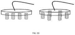
- FIG. 10shows an alternate embodiment of an array of probes in a linear arrangement and a polygonal arrangement.
- Dielectric spectroscopyis a near field measurement technique that is based on the passive electrical properties of a material, the capacitance C, and the conductance G.
- the sampleis placed between two electrodes with an oscillating electric field; the material properties of the sample between the two electrodes respond with the changing field to amplify or attenuate the signal depending of the frequency of oscillation.
- the relative permittivity et and conductivity kdescribe the relation independent from the electrodes given by the following equations:
- FIG. 1illustrates the impedance and phase response across frequencies for various cellular properties.
- FIG. 2illustrates the current flow between cells comparing normal and abnormal tissue.
- the solid linescorrespond to the current flow due to low frequency signals, while the dashed lines correspond to current paths at higher frequency signals.
- the currentis able to permeate cell membranes, which effectively probe their physical properties.
- Low frequenciesdo not permeate the cell membranes due to the polarized nature of cells.
- the cellsare able to rotate and align with the fields.
- the RF fieldis able to permeate the cell membrane and allows for measurements inside the cell.
- physical properties of the samplewill change as the cells become unviable or deviate from the intended bioproduct.
- FIG. 2abnormal cells are illustrated. As cell membranes start to break down the low frequency signals will start to have paths that pass through the cells themselves, leading to a range of significantly different impedance values.
- Near field dielectric spectroscopy measurementscan be performed on both 2D and 3D cell cultures.
- broadband RF spectral datais acquired. Broadband data is collected with the intact cell culture. Wide band spectral measurements will be collected with frequencies ranging from 1 MHz to 1000 MHz to cover the range of measurements relevant to cellular environments. These parameters including: biomass, cell size, intracellular matrix, cellular membrane health, subcellular matrix properties.
- RFRadio Frequency
- An advantage to using reflective tomographyis that it can operate at a lower emission power in that it is not necessary to completely penetrate the target sample.
- the antenna or antennasare arranged to receive the reflections. Where more than one receiving antenna is used one embodiment is a generally linear alignment of the antennae. Another embodiment is to arrange the antennae in a generally semicircular fashion.
- the signalsreflect, refract, and deflect at specific angles, dependent on the material properties at each interface. See FIG. 3 .
- the phase and polarizationcan change and provide information about the interior structure of the material and detect boundaries between different materials.
- many receiver antennasare used to calculate difference in multiple directions, to give an advanced image of interfaces of the materials.
- the RF tomography approachutilizing 1-40 GHz, will enable property measurements at all levels of the culture, layer by layer.
- FIG. 4A perspective view of a resonant cell is shown in FIG. 4 .
- the cell and its connection to a biomaterial identification deviceis shown.
- the radio tomography probes, antennas,are shown inside the cell with the dielectric probe shown on the bottom, outside of the cell.
- FIG. 5is a plan view showing a semi-fractal antenna.
- FIG. 6Is an embodiment with the cell connected to an RF power supply connected to the cell and the probes; the dielectric and far field probes are connected to a sensitive detector 600 and computer controller 630 .
- the far field RF probes/antennasare in a polygonal patter and the near field dielectric antenna/probes are positioned on the side of the resonant cell.
- FIG. 7shows a block diagram of the antennas 586 , sensitive detector 500 connected to the analysis circuits 630 .
- the sensitive detector 500has an input from antenna 586 through cable 588 at input port 582 .
- the sensitive detector 600acquires the signal 584 .
- the signal 584is received by a Low Noise Amplifier 508 and is divided by a splitter 510 .
- a tuner 512receives the signal from the splitter 510 and is converted by an Analog to Digital Converter (ADC) 514 .
- ADCAnalog to Digital Converter
- a sensitive detectorpreferably has a sensitivity of ⁇ 170 dB at room temperature, 4 dB higher than the theoretical limit.
- a standard rangeis between 30 MHz to 1000 MHz, but the detector is not limited to this range and can be modified by replacing the tuning system for different frequency range.
- a FPGA/CPU 556receives the signal from the ADC 514 and preferably, a clock 570 .
- the FPGAhas a display controller 510 and a keyboard controller 512 .
- the FPGAcommunicates with RAM memory 518 and preferably an EPROM 538 .
- the FPGAoutputs to USB physical layer 550 at output port 552 .
- the unit 500has an internal and/or external power supply 560 .
- FIG. 8Another embodiment is shown in FIG. 8 .
- a sensitive detector 604has an LNA 602 is connected to a tuner 606 .
- the tuneroutputs a signal to an ADC 608 .
- the digital signalis down converted by a Digital Down Converter (DDC) 610 .
- the down converted signalis received by a frequency domain Fourier Transform (FT) device 614 .
- the FTtakes a signal in the time domain and converts it into the frequency domain.
- DDCDigital Down Converter
- FTfrequency domain Fourier Transform
- the biologic property measurement device 630receives the signals from the sensitive detector and applies wavelet denoising 622 . It then integrates the time or frequency bins. The frequency domain pattern is enhanced with noise cancelation 618 and a signature is created 616 . The frequency domain signal processing pattern recognition 624 is performed against a known signature base line pattern. A threshold is applied against the processed signal to determine whether the sample status is abnormal.
- the apparatushas at least one logic circuit to combine a plurality of signals received from an array of a plurality of antennas.
- the combining of signals and windowing the signalscreates of more coherent signal suitable for analysis.
- FIG. 9is illustrative diagram of the sampling of a plurality of signals in the operation of the device.
- Each non-distorted signal, x 1 550 through xN 552is combined 510 through synchronizing the signals with their independent time delays based on positions 502 - 522 , applying a windowing function 504 - 524 and then Finite Impulse Response filter 506 - 526 .
- the resulting signal 512is further windowed to remove cluttered signal and the energy 514 is calculated from the resulting windowed signal 512 .
- the purpose of thisis to remove noise from the measurements, as well as removing the strongest influence of the reflected signals, typically from the surface boundary. This is required to acquire the most sensitive signals from the internal structure.
- FIG. 10shows an alternate embodiment of an array of probes in a linear arrangement and a polygonal arrangement.
- the presently preferred embodiment of the deviceis benchtop system as shown. It can be configured to assess 3D cell cultures, tissue samples and proteins.
- Another embodimentwould be to have the apparatus continuously monitoring cell cultures in an industrial setting.
- Another embodimentwould be to have the apparatus monitoring food for the presence of contamination by bacteria.
- Another embodiment of the deviceis configured to monitor existing cell culture incubators to provide real-time assessment of cellular health.
Landscapes
- Health & Medical Sciences (AREA)
- Engineering & Computer Science (AREA)
- Life Sciences & Earth Sciences (AREA)
- Physics & Mathematics (AREA)
- Chemical & Material Sciences (AREA)
- Biomedical Technology (AREA)
- General Health & Medical Sciences (AREA)
- Biochemistry (AREA)
- General Physics & Mathematics (AREA)
- Analytical Chemistry (AREA)
- Immunology (AREA)
- Pathology (AREA)
- Biophysics (AREA)
- Molecular Biology (AREA)
- Bioinformatics & Cheminformatics (AREA)
- Zoology (AREA)
- Theoretical Computer Science (AREA)
- Organic Chemistry (AREA)
- General Engineering & Computer Science (AREA)
- Wood Science & Technology (AREA)
- Optics & Photonics (AREA)
- Urology & Nephrology (AREA)
- Food Science & Technology (AREA)
- Medicinal Chemistry (AREA)
- Hematology (AREA)
- Genetics & Genomics (AREA)
- Evolutionary Computation (AREA)
- Microbiology (AREA)
- Biotechnology (AREA)
- Chemical Kinetics & Catalysis (AREA)
- Electrochemistry (AREA)
- Artificial Intelligence (AREA)
- Computational Linguistics (AREA)
- Data Mining & Analysis (AREA)
- Sustainable Development (AREA)
- Computing Systems (AREA)
- Mathematical Physics (AREA)
- Software Systems (AREA)
- Electromagnetism (AREA)
- Apparatus Associated With Microorganisms And Enzymes (AREA)
Abstract
Description
Claims (15)
Priority Applications (1)
| Application Number | Priority Date | Filing Date | Title |
|---|---|---|---|
| US16/008,501US11300558B2 (en) | 2018-06-14 | 2018-06-14 | Apparatus and system for spectroscopy and tomography of fragile biologic materials |
Applications Claiming Priority (1)
| Application Number | Priority Date | Filing Date | Title |
|---|---|---|---|
| US16/008,501US11300558B2 (en) | 2018-06-14 | 2018-06-14 | Apparatus and system for spectroscopy and tomography of fragile biologic materials |
Publications (2)
| Publication Number | Publication Date |
|---|---|
| US20190383787A1 US20190383787A1 (en) | 2019-12-19 |
| US11300558B2true US11300558B2 (en) | 2022-04-12 |
Family
ID=68840674
Family Applications (1)
| Application Number | Title | Priority Date | Filing Date |
|---|---|---|---|
| US16/008,501Active2039-12-08US11300558B2 (en) | 2018-06-14 | 2018-06-14 | Apparatus and system for spectroscopy and tomography of fragile biologic materials |
Country Status (1)
| Country | Link |
|---|---|
| US (1) | US11300558B2 (en) |
Families Citing this family (2)
| Publication number | Priority date | Publication date | Assignee | Title |
|---|---|---|---|---|
| CN111314329B (en)* | 2020-02-03 | 2022-01-28 | 杭州迪普科技股份有限公司 | Traffic intrusion detection system and method |
| JP6977977B1 (en)* | 2020-06-24 | 2021-12-08 | エピストラ株式会社 | Medium abnormality detection device and abnormality detection method |
Citations (39)
| Publication number | Priority date | Publication date | Assignee | Title |
|---|---|---|---|---|
| US5130661A (en)* | 1988-01-20 | 1992-07-14 | The University Of Manchester Institute Of Science And Tech. | Tomographic flow imaging system |
| US5715819A (en)* | 1994-05-26 | 1998-02-10 | The Carolinas Heart Institute | Microwave tomographic spectroscopy system and method |
| US20010051774A1 (en)* | 2000-02-28 | 2001-12-13 | Peter Littrup | Multidimensional bioelectrical tissue analyzer |
| US6387671B1 (en)* | 1999-07-21 | 2002-05-14 | The Regents Of The University Of California | Electrical impedance tomography to control electroporation |
| US6403348B1 (en)* | 1999-07-21 | 2002-06-11 | The Regents Of The University Of California | Controlled electroporation and mass transfer across cell membranes |
| US20020137121A1 (en)* | 1999-07-21 | 2002-09-26 | Boris Rubinsky | Cell viability detection using electrical measurements |
| US6482619B1 (en)* | 1999-07-21 | 2002-11-19 | The Regents Of The University Of California | Cell/tissue analysis via controlled electroporation |
| US6885191B1 (en)* | 2001-02-13 | 2005-04-26 | Stuart M. Gleman | Radio-frequency imaging system for medical and other applications |
| US7119553B2 (en)* | 2003-06-11 | 2006-10-10 | Konsulteurope Limited Limited Joint Stock Company | Security scanners with capacitance and magnetic sensor arrays |
| US7312742B2 (en)* | 2005-05-31 | 2007-12-25 | L-3 Communications Security And Detection Systems, Inc. | Computerized tomography using radar |
| US20090039900A1 (en)* | 2006-07-14 | 2009-02-12 | Covidien Ag | Surgical Testing Instrument and System |
| US7496450B2 (en)* | 2003-08-22 | 2009-02-24 | Instituto Mexicano Del Petroleo | Method for imaging multiphase flow using electrical capacitance tomography |
| US7671784B2 (en)* | 2005-05-31 | 2010-03-02 | L-3 Communications Cyterra Corporation | Computerized tomography using radar |
| US20110109328A1 (en)* | 2008-03-07 | 2011-05-12 | Agrichem, Inc. | Flush-Mounted Capacitive Sensor Mount |
| US20130214797A1 (en)* | 2012-01-20 | 2013-08-22 | Seuffer gmbH & Co. KG | Sensor apparatus for detecting properties of liquid |
| US8762084B2 (en)* | 2009-06-30 | 2014-06-24 | The University Of Connecticut | Multiple excitation capacitance polling for enhanced electronic capacitance tomography |
| US20140182362A1 (en)* | 2012-12-28 | 2014-07-03 | General Electric Company | Systems for analysis of fluids |
| US20140218230A1 (en)* | 2011-07-01 | 2014-08-07 | University Of Manitoba | Imaging using probes |
| US20150097579A1 (en)* | 2012-05-30 | 2015-04-09 | General Electric Company | Sensor apparatus for measurement of material properties |
| US20150168313A1 (en)* | 2012-05-22 | 2015-06-18 | Baylor University | System and method for permittivity distributions with transit time and dispersion tomography |
| US20150338364A1 (en)* | 2012-10-31 | 2015-11-26 | The University Of Connecticut | Multiple-excitation multiple-receiving (memr) capacitance tomography |
| US20160091448A1 (en)* | 2013-05-13 | 2016-03-31 | The University Of Bath | Apparatus and method for measuring electromagnetic properties |
| US20160377557A1 (en)* | 2014-03-12 | 2016-12-29 | National University Corporation Kobe University | Scattering tomography method and scattering tomography device |
| US20170156646A1 (en)* | 2014-09-29 | 2017-06-08 | Zyomed Corp. | Systems and methods for noninvasive blood glucose and other analyte detection and measurement using collision computing |
| US20170188874A1 (en)* | 2015-09-29 | 2017-07-06 | Avraham Suhami | Linear Velocity Imaging Tomography |
| US20180074103A1 (en)* | 2016-09-09 | 2018-03-15 | Oz Optics Ltd. | Multi-view planar near-field scattering tomography system |
| US9933380B2 (en)* | 2014-11-28 | 2018-04-03 | Commissariat à l'énergie atomique et aux énergies alternatives | Method for imaging a medium through electrical measurements with a contact impedance correction |
| US20180206760A1 (en)* | 2005-06-09 | 2018-07-26 | The Regents Of The University Of California | Volumetric induction phase shift detection system for determining tissue water content properties |
| US10041899B2 (en)* | 2016-03-03 | 2018-08-07 | Umm Al-Qura University | Portable electrical capacitive tomography imaging device and method of operation |
| US20180313969A1 (en)* | 2017-05-01 | 2018-11-01 | Z˜Communications, Inc. | Multi-capacitor liquid detection device and method(s) of use |
| US20180325414A1 (en)* | 2017-05-12 | 2018-11-15 | Tech4Imaging Llc | Electro-magneto volume tomography system and methodology for non-invasive volume tomography |
| US10197508B2 (en)* | 2014-07-07 | 2019-02-05 | Univeristy Of Manitoba | Imaging using reconfigurable antennas |
| US20190170677A1 (en)* | 2017-12-05 | 2019-06-06 | Airbus Helicopters | Method for non-intrusively detecting imperfections in a test object |
| US20190266436A1 (en)* | 2018-02-26 | 2019-08-29 | General Electric Company | Machine learning in an imaging modality service context |
| US20190285562A1 (en)* | 2018-03-13 | 2019-09-19 | Ryan Wade Penny | Methods and systems for high fidelity electrical tomographic processes |
| US20190317026A1 (en)* | 2016-12-09 | 2019-10-17 | Nanyang Technological University | Non-destructive testing methods and apparatus |
| US20200003670A1 (en)* | 2016-01-21 | 2020-01-02 | Atout Process Limited | Method and apparatus for determining properties of a contained fluid |
| US10551339B2 (en)* | 2016-05-11 | 2020-02-04 | Tech4Imaging Llc | Smart capacitance sensors for use with electrical capacitance volume tomography and capacitance sensing applications |
| US11083393B2 (en)* | 2017-02-06 | 2021-08-10 | The Regents Of The University Of California | Non-contact tomographic imaging and thin film sensors for sensing permittivity changes |
- 2018
- 2018-06-14USUS16/008,501patent/US11300558B2/enactiveActive
Patent Citations (40)
| Publication number | Priority date | Publication date | Assignee | Title |
|---|---|---|---|---|
| US5130661A (en)* | 1988-01-20 | 1992-07-14 | The University Of Manchester Institute Of Science And Tech. | Tomographic flow imaging system |
| US5715819A (en)* | 1994-05-26 | 1998-02-10 | The Carolinas Heart Institute | Microwave tomographic spectroscopy system and method |
| US6387671B1 (en)* | 1999-07-21 | 2002-05-14 | The Regents Of The University Of California | Electrical impedance tomography to control electroporation |
| US6403348B1 (en)* | 1999-07-21 | 2002-06-11 | The Regents Of The University Of California | Controlled electroporation and mass transfer across cell membranes |
| US20020137121A1 (en)* | 1999-07-21 | 2002-09-26 | Boris Rubinsky | Cell viability detection using electrical measurements |
| US6482619B1 (en)* | 1999-07-21 | 2002-11-19 | The Regents Of The University Of California | Cell/tissue analysis via controlled electroporation |
| US20010051774A1 (en)* | 2000-02-28 | 2001-12-13 | Peter Littrup | Multidimensional bioelectrical tissue analyzer |
| US6885191B1 (en)* | 2001-02-13 | 2005-04-26 | Stuart M. Gleman | Radio-frequency imaging system for medical and other applications |
| US7119553B2 (en)* | 2003-06-11 | 2006-10-10 | Konsulteurope Limited Limited Joint Stock Company | Security scanners with capacitance and magnetic sensor arrays |
| US7295019B2 (en)* | 2003-06-11 | 2007-11-13 | Konsulteurope Limited Limited Liability Joint Stock Company United Kingdon | Security scanners with capacitance and magnetic sensor arrays |
| US7496450B2 (en)* | 2003-08-22 | 2009-02-24 | Instituto Mexicano Del Petroleo | Method for imaging multiphase flow using electrical capacitance tomography |
| US7312742B2 (en)* | 2005-05-31 | 2007-12-25 | L-3 Communications Security And Detection Systems, Inc. | Computerized tomography using radar |
| US7671784B2 (en)* | 2005-05-31 | 2010-03-02 | L-3 Communications Cyterra Corporation | Computerized tomography using radar |
| US20180206760A1 (en)* | 2005-06-09 | 2018-07-26 | The Regents Of The University Of California | Volumetric induction phase shift detection system for determining tissue water content properties |
| US20090039900A1 (en)* | 2006-07-14 | 2009-02-12 | Covidien Ag | Surgical Testing Instrument and System |
| US20110109328A1 (en)* | 2008-03-07 | 2011-05-12 | Agrichem, Inc. | Flush-Mounted Capacitive Sensor Mount |
| US8762084B2 (en)* | 2009-06-30 | 2014-06-24 | The University Of Connecticut | Multiple excitation capacitance polling for enhanced electronic capacitance tomography |
| US20140218230A1 (en)* | 2011-07-01 | 2014-08-07 | University Of Manitoba | Imaging using probes |
| US20130214797A1 (en)* | 2012-01-20 | 2013-08-22 | Seuffer gmbH & Co. KG | Sensor apparatus for detecting properties of liquid |
| US20150168313A1 (en)* | 2012-05-22 | 2015-06-18 | Baylor University | System and method for permittivity distributions with transit time and dispersion tomography |
| US20150097579A1 (en)* | 2012-05-30 | 2015-04-09 | General Electric Company | Sensor apparatus for measurement of material properties |
| US20150338364A1 (en)* | 2012-10-31 | 2015-11-26 | The University Of Connecticut | Multiple-excitation multiple-receiving (memr) capacitance tomography |
| US20140182362A1 (en)* | 2012-12-28 | 2014-07-03 | General Electric Company | Systems for analysis of fluids |
| US20160091448A1 (en)* | 2013-05-13 | 2016-03-31 | The University Of Bath | Apparatus and method for measuring electromagnetic properties |
| US20160377557A1 (en)* | 2014-03-12 | 2016-12-29 | National University Corporation Kobe University | Scattering tomography method and scattering tomography device |
| US10197508B2 (en)* | 2014-07-07 | 2019-02-05 | Univeristy Of Manitoba | Imaging using reconfigurable antennas |
| US20170156646A1 (en)* | 2014-09-29 | 2017-06-08 | Zyomed Corp. | Systems and methods for noninvasive blood glucose and other analyte detection and measurement using collision computing |
| US9933380B2 (en)* | 2014-11-28 | 2018-04-03 | Commissariat à l'énergie atomique et aux énergies alternatives | Method for imaging a medium through electrical measurements with a contact impedance correction |
| US20170188874A1 (en)* | 2015-09-29 | 2017-07-06 | Avraham Suhami | Linear Velocity Imaging Tomography |
| US20200003670A1 (en)* | 2016-01-21 | 2020-01-02 | Atout Process Limited | Method and apparatus for determining properties of a contained fluid |
| US10041899B2 (en)* | 2016-03-03 | 2018-08-07 | Umm Al-Qura University | Portable electrical capacitive tomography imaging device and method of operation |
| US10551339B2 (en)* | 2016-05-11 | 2020-02-04 | Tech4Imaging Llc | Smart capacitance sensors for use with electrical capacitance volume tomography and capacitance sensing applications |
| US20180074103A1 (en)* | 2016-09-09 | 2018-03-15 | Oz Optics Ltd. | Multi-view planar near-field scattering tomography system |
| US20190317026A1 (en)* | 2016-12-09 | 2019-10-17 | Nanyang Technological University | Non-destructive testing methods and apparatus |
| US11083393B2 (en)* | 2017-02-06 | 2021-08-10 | The Regents Of The University Of California | Non-contact tomographic imaging and thin film sensors for sensing permittivity changes |
| US20180313969A1 (en)* | 2017-05-01 | 2018-11-01 | Z˜Communications, Inc. | Multi-capacitor liquid detection device and method(s) of use |
| US20180325414A1 (en)* | 2017-05-12 | 2018-11-15 | Tech4Imaging Llc | Electro-magneto volume tomography system and methodology for non-invasive volume tomography |
| US20190170677A1 (en)* | 2017-12-05 | 2019-06-06 | Airbus Helicopters | Method for non-intrusively detecting imperfections in a test object |
| US20190266436A1 (en)* | 2018-02-26 | 2019-08-29 | General Electric Company | Machine learning in an imaging modality service context |
| US20190285562A1 (en)* | 2018-03-13 | 2019-09-19 | Ryan Wade Penny | Methods and systems for high fidelity electrical tomographic processes |
Also Published As
| Publication number | Publication date |
|---|---|
| US20190383787A1 (en) | 2019-12-19 |
Similar Documents
| Publication | Publication Date | Title |
|---|---|---|
| Vasquez et al. | Noninvasive inline food inspection via microwave imaging technology: An application example in the food industry | |
| Pliquett | Bioimpedance: a review for food processing | |
| Huang et al. | Tissue characterization using terahertz pulsed imaging in reflection geometry | |
| Naderi-Boldaji et al. | Dielectric power spectroscopy as a potential technique for the non-destructive measurement of sugar concentration in sugarcane | |
| US20170199134A1 (en) | Imaging using reconfigurable antennas | |
| Harnsoongnoen et al. | Real-time monitoring of sucrose, sorbitol, D-glucose and D-fructose concentration by electromagnetic sensing | |
| US9863900B2 (en) | Planar sensor array for non-destructive evaluation of material using electromagnetic impedance | |
| CN104856678A (en) | Microwave detection system for complex foreign matters in vivo based on template signal similarity | |
| US11300558B2 (en) | Apparatus and system for spectroscopy and tomography of fragile biologic materials | |
| Gabriel et al. | Use of time domain spectroscopy for measuring dielectric properties with a coaxial probe | |
| CN106018548A (en) | Ultrasonic online detection method and system for uniformity of solid-liquid two-phase mixture | |
| US20180100819A1 (en) | System, device and method for testing an object | |
| JP2019100912A (en) | Identification device of substance using electromagnetic wave and identification method | |
| Reinecke et al. | Low-cost sensor system for non-invasive monitoring of cell growth in disposable bioreactors | |
| WO2009063497A2 (en) | A multipurpose instrument for measurement of dielectric properties | |
| Nelson et al. | Investigation of dielectric sensing for fruit quality determination | |
| US12379329B2 (en) | RF rapid diagnostics of infection and contamination | |
| Nelson et al. | Study of fruit permittivity measurements for quality detection | |
| Soltani et al. | Use of dielectric properties in quality measurement of agricultural products | |
| EbrahimiZadeh et al. | Electromagnetic Time-Reversal Technique for Monitoring Skull Healing Stages | |
| Naskar et al. | Design and Development of a Low-Cost Milk Analyzer | |
| Kaur et al. | Graphene based microwave sensor for determining dielectric permittivity of different materials for food evaluation application | |
| Di Natale et al. | Liquid Identification through SDR: System Design and Performance Analysis | |
| US10921274B2 (en) | Apparatus for in vivo dielectric spectroscopy | |
| Rashed et al. | Developing an Interference-Free Non-Destructive Microwave Testing System for Liquid Samples |
Legal Events
| Date | Code | Title | Description |
|---|---|---|---|
| FEPP | Fee payment procedure | Free format text:ENTITY STATUS SET TO UNDISCOUNTED (ORIGINAL EVENT CODE: BIG.); ENTITY STATUS OF PATENT OWNER: SMALL ENTITY | |
| FEPP | Fee payment procedure | Free format text:ENTITY STATUS SET TO SMALL (ORIGINAL EVENT CODE: SMAL); ENTITY STATUS OF PATENT OWNER: SMALL ENTITY | |
| STPP | Information on status: patent application and granting procedure in general | Free format text:NON FINAL ACTION MAILED | |
| STPP | Information on status: patent application and granting procedure in general | Free format text:RESPONSE TO NON-FINAL OFFICE ACTION ENTERED AND FORWARDED TO EXAMINER | |
| STPP | Information on status: patent application and granting procedure in general | Free format text:FINAL REJECTION MAILED | |
| STPP | Information on status: patent application and granting procedure in general | Free format text:RESPONSE AFTER FINAL ACTION FORWARDED TO EXAMINER | |
| STPP | Information on status: patent application and granting procedure in general | Free format text:NON FINAL ACTION MAILED | |
| STPP | Information on status: patent application and granting procedure in general | Free format text:RESPONSE TO NON-FINAL OFFICE ACTION ENTERED AND FORWARDED TO EXAMINER | |
| STPP | Information on status: patent application and granting procedure in general | Free format text:NOTICE OF ALLOWANCE MAILED -- APPLICATION RECEIVED IN OFFICE OF PUBLICATIONS | |
| AS | Assignment | Owner name:NOKOMIS, INC., PENNSYLVANIA Free format text:ASSIGNMENT OF ASSIGNORS INTEREST;ASSIGNORS:UPLINGER, JAMES ROBERT, II;MAKARENKO, VLADIMIR;REEL/FRAME:059211/0061 Effective date:20220309 | |
| STPP | Information on status: patent application and granting procedure in general | Free format text:PUBLICATIONS -- ISSUE FEE PAYMENT VERIFIED | |
| STCF | Information on status: patent grant | Free format text:PATENTED CASE | |
| MAFP | Maintenance fee payment | Free format text:PAYMENT OF MAINTENANCE FEE, 4TH YR, SMALL ENTITY (ORIGINAL EVENT CODE: M2551); ENTITY STATUS OF PATENT OWNER: SMALL ENTITY Year of fee payment:4 |