US11300054B2 - Fuel flow control system and method for engine start - Google Patents
Fuel flow control system and method for engine startDownload PDFInfo
- Publication number
- US11300054B2 US11300054B2US16/184,297US201816184297AUS11300054B2US 11300054 B2US11300054 B2US 11300054B2US 201816184297 AUS201816184297 AUS 201816184297AUS 11300054 B2US11300054 B2US 11300054B2
- Authority
- US
- United States
- Prior art keywords
- aircraft engine
- fuel
- flameout
- schedule
- open loop
- Prior art date
- Legal status (The legal status is an assumption and is not a legal conclusion. Google has not performed a legal analysis and makes no representation as to the accuracy of the status listed.)
- Active, expires
Links
Images


Classifications
- F—MECHANICAL ENGINEERING; LIGHTING; HEATING; WEAPONS; BLASTING
- F02—COMBUSTION ENGINES; HOT-GAS OR COMBUSTION-PRODUCT ENGINE PLANTS
- F02C—GAS-TURBINE PLANTS; AIR INTAKES FOR JET-PROPULSION PLANTS; CONTROLLING FUEL SUPPLY IN AIR-BREATHING JET-PROPULSION PLANTS
- F02C7/00—Features, components parts, details or accessories, not provided for in, or of interest apart form groups F02C1/00 - F02C6/00; Air intakes for jet-propulsion plants
- F02C7/26—Starting; Ignition
- F02C7/262—Restarting after flame-out
- F—MECHANICAL ENGINEERING; LIGHTING; HEATING; WEAPONS; BLASTING
- F02—COMBUSTION ENGINES; HOT-GAS OR COMBUSTION-PRODUCT ENGINE PLANTS
- F02C—GAS-TURBINE PLANTS; AIR INTAKES FOR JET-PROPULSION PLANTS; CONTROLLING FUEL SUPPLY IN AIR-BREATHING JET-PROPULSION PLANTS
- F02C9/00—Controlling gas-turbine plants; Controlling fuel supply in air- breathing jet-propulsion plants
- F02C9/26—Control of fuel supply
- F—MECHANICAL ENGINEERING; LIGHTING; HEATING; WEAPONS; BLASTING
- F02—COMBUSTION ENGINES; HOT-GAS OR COMBUSTION-PRODUCT ENGINE PLANTS
- F02C—GAS-TURBINE PLANTS; AIR INTAKES FOR JET-PROPULSION PLANTS; CONTROLLING FUEL SUPPLY IN AIR-BREATHING JET-PROPULSION PLANTS
- F02C3/00—Gas-turbine plants characterised by the use of combustion products as the working fluid
- F02C3/04—Gas-turbine plants characterised by the use of combustion products as the working fluid having a turbine driving a compressor
- F02C3/06—Gas-turbine plants characterised by the use of combustion products as the working fluid having a turbine driving a compressor the compressor comprising only axial stages
- F—MECHANICAL ENGINEERING; LIGHTING; HEATING; WEAPONS; BLASTING
- F02—COMBUSTION ENGINES; HOT-GAS OR COMBUSTION-PRODUCT ENGINE PLANTS
- F02C—GAS-TURBINE PLANTS; AIR INTAKES FOR JET-PROPULSION PLANTS; CONTROLLING FUEL SUPPLY IN AIR-BREATHING JET-PROPULSION PLANTS
- F02C7/00—Features, components parts, details or accessories, not provided for in, or of interest apart form groups F02C1/00 - F02C6/00; Air intakes for jet-propulsion plants
- F02C7/26—Starting; Ignition
- F—MECHANICAL ENGINEERING; LIGHTING; HEATING; WEAPONS; BLASTING
- F05—INDEXING SCHEMES RELATING TO ENGINES OR PUMPS IN VARIOUS SUBCLASSES OF CLASSES F01-F04
- F05D—INDEXING SCHEME FOR ASPECTS RELATING TO NON-POSITIVE-DISPLACEMENT MACHINES OR ENGINES, GAS-TURBINES OR JET-PROPULSION PLANTS
- F05D2220/00—Application
- F05D2220/30—Application in turbines
- F05D2220/32—Application in turbines in gas turbines
- F—MECHANICAL ENGINEERING; LIGHTING; HEATING; WEAPONS; BLASTING
- F05—INDEXING SCHEMES RELATING TO ENGINES OR PUMPS IN VARIOUS SUBCLASSES OF CLASSES F01-F04
- F05D—INDEXING SCHEME FOR ASPECTS RELATING TO NON-POSITIVE-DISPLACEMENT MACHINES OR ENGINES, GAS-TURBINES OR JET-PROPULSION PLANTS
- F05D2270/00—Control
- F05D2270/01—Purpose of the control system
- F05D2270/09—Purpose of the control system to cope with emergencies
- F05D2270/092—Purpose of the control system to cope with emergencies in particular blow-out and relight
Definitions
- the present disclosurerelates generally to fuel flow control for engine start.
- a method for controlling fuel flow to an engine during startcomprises causing fuel to be injected into a combustor of the engine according to a first fuel schedule defining a minimum fuel flow limit required to achieve light-off of the engine, the minimum fuel flow limit set at an initial value, monitoring, following light-off of the engine, at least one operating parameter of the engine, detecting, based on the at least one operating parameter, occurrence of flameout in the engine, and, in response to detecting occurrence of flameout in the engine, increasing the minimum fuel flow limit from the initial value to a first value to obtain an adjusted fuel schedule, and causing fuel to be injected into the combustor according to the adjusted fuel schedule.
- a system for controlling fuel flow to an engine during startcomprises at least one processing unit and at least one non-transitory computer-readable memory having stored thereon program instructions executable by the at least one processing unit for causing fuel to be injected into a combustor of the engine according to a first fuel schedule defining a minimum fuel flow limit required to achieve light-off of the engine, the minimum fuel flow limit set at an initial value, monitoring, following light-off of the engine, at least one operating parameter of the engine, detecting, based on the at least one operating parameter, occurrence of flameout in the engine, and, in response to detecting occurrence of flameout in the engine, increasing the minimum fuel flow limit from the initial value to a first value to obtain an adjusted fuel schedule, and causing fuel to be injected into the combustor according to the adjusted fuel schedule.
- a non-transitory computer readable mediumhaving stored thereon program code executable by at least one processor for causing fuel to be injected into a combustor of the engine according to a first fuel schedule defining a minimum fuel flow limit required to achieve light-off of the engine, the minimum fuel flow limit set at an initial value, monitoring, following light-off of the engine, at least one operating parameter of the engine, detecting, based on the at least one operating parameter, occurrence of flameout in the engine, and, in response to detecting occurrence of flameout the engine, increasing the minimum fuel flow limit from the initial value to a first value to obtain an adjusted fuel schedule, and causing fuel to be injected into the combustor according to the adjusted fuel schedule.
- FIG. 1is a schematic cross-sectional view of a gas turbine engine, in accordance with an illustrative embodiment
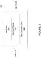
- FIG. 2is a block diagram of a system for controlling fuel flow during start of the engine of FIG. 1 , in accordance with an illustrative embodiment
- FIG. 3is a block diagram of a computing device for implementing the system of FIG. 2 , in accordance with an illustrative embodiment.
- FIG. 4is a flowchart of a method for controlling fuel flow during start of the engine of FIG. 1 , in accordance with an illustrative embodiment
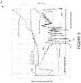
- FIG. 5is a plot of fuel flow and gas generator acceleration as a function of gas generator speed, in accordance with an illustrative embodiment.
- FIG. 1illustrates a gas turbine engine 10 of a type preferably provided for use in subsonic flight, generally comprising in serial flow communication, a fan 12 through which ambient air is propelled, a compressor section 14 for pressurizing the air, a combustor 16 in which the compressed air is mixed with fuel and ignited for generating an annular stream of hot combustion gases, and a turbine section 18 for extracting energy from the combustion gases.
- High pressure rotor(s) 20 of the turbine section 18are drivingly engaged to high pressure rotor(s) 22 of the compressor section 14 through a high pressure shaft 24 .
- Low pressure rotor(s) 26 of the turbine section 18are drivingly engaged to the fan rotor 12 and to other low pressure rotor(s) (not shown) of the compressor section 14 through a low pressure shaft 28 extending within the high pressure shaft 24 and rotating independently therefrom.
- gas turbine engine 10may alternatively be another type of engine, for example a turboshaft engine, also generally comprising in serial flow communication a compressor section, a combustor, and a turbine section, and a fan through which ambient air is propelled.
- a turboprop enginemay also apply.
- the engine 10is described herein for flight applications, it should be understood that other uses, such as industrial or the like, may apply.
- the starting (or start-up) process of the gas turbine engine 10illustratively comprises two consecutive phases.
- the high pressure rotor(s) 22 of the compressor section 14are rotated by a torque provided by an external source, such as a starter (not shown), in order to provide air flow into the combustor 16 .
- an external sourcesuch as a starter (not shown)
- fuel flowis then injected into the combustor 16 at a controlled rate.
- an electronic engine controller (EEC) 202illustratively outputs one or more control signals to a fuel control unit 204 to cause the injection of fuel flow.
- the fuel control unit 204comprises a fuel pump and a stepper (not shown), a torque motor valve (not shown), or any suitable equivalent means for injecting fuel into the combustor 16 .
- the EEC 202may be part of a Full Authority Digital Engine Control (FADEC), which is used to control the operation and performance of the engine 10 .
- the EEC 202selects the appropriate fuel schedule for the light-off procedure by querying a memory storing one or more fuel schedules.
- the memorymay also store therein all data (e.g., engine operating parameters) sensed or measured as well as other predetermined data and programs.
- the fuel schedulewhich is selected in the first phase of the engine starting process, follows an open loop fuel flow profile in which fuel flow is commanded based on a desired rotational speed of the compressor section 14 .
- the fuel schedulemay thus be referred to herein as an “open loop fuel schedule” and the first phase may be referred to as direct fuel flow control.
- the fuel flowis injected to mix with the air flow and the mixture is then exposed to an ignition source (e.g., a spark igniter, not shown).
- an ignition sourcee.g., a spark igniter, not shown.
- Light-off of the combustion processoccurs in the combustor 16 when an appropriate fuel/air ratio is reached, resulting in ignition of the engine 10 .
- the light-off occurrenceis detected by monitoring an exhaust temperature of the engine 10 , with light-off being detected when the exhaust temperature reaches a threshold temperature (e.g., 200° F.).
- the inter-stage turbine temperature (ITT)which is the temperature of the exhaust gases between the high and low pressure turbines of the engine 10 , is used as the exhaust temperature.
- the exhaust temperaturemay be monitored using a temperature sensor (not shown) associated with an exhaust outlet (not shown) of the engine 10 .
- an ultraviolet or photoelectric signalwhich may be generated by any suitable flame detection measurement system and indicates the presence of visible flames at the exhaust outlet of the engine 10 , may be monitored by the EEC 202 to detect light-off.
- light-offcan be detected following a predetermined increase in the inter-stage turbine temperature.
- light-offis detected when the gas generator (i.e. engine speed reaches a predetermined value. Other embodiments may apply.
- the fuel flowis continuously injected into the combustor 16 , thus enabling local ignition to propagate and spread so as to form stable combustion in the combustor 16 .
- the speed of the engine 10is then accelerated by increasing the injection of fuel flow until the engine 10 operates under a self-sustained speed.
- the fuel flowis injected according to a fuel schedule required for operation of the engine 10 from light-off to a self-sustaining condition.
- the appropriate fuel scheduleis selected by the EEC 202 .
- the fuel schedulefollows a closed loop fuel profile in which fuel flow is commanded to achieve a desired acceleration of the compressor section 14 .
- the fuel schedulemay thus be referred to herein as a “closed loop fuel schedule” and the second phase may be referred to as sub-idle acceleration governing or closed loop sub-idle acceleration scheduling.
- the EEC 202is used to adjust fuel flow to the combustor 16 upon detection of engine flameout during start of the engine 10 .
- the engine startmay occur in-flight or on the ground.
- flameoutrefers to the run-down of the engine 10 that may be caused by the extinction of the flame in chamber(s) of the combustor 16 .
- the combustor 16does not burn all of the fuel supplied to it, which in turn reduces the overall engine performance and efficiency. When flameout only occurs in some, but not all, (i.e.
- partial flameoutFor engines having a single combustion chamber, partial flameout is observed when flameout occurs in a section of the chamber. When flameout occurs in all chambers of the combustor 16 , it is referred to as “complete flameout” or “full flameout”. As known to those skilled in the art, flameout may be caused by high velocity air entering the engine 10 . Flameout may also be caused by improper fuel-air mixture or interruption of the airflow through the engine 10 . This may be the result of a given engine operating condition, such as acceleration of the engine 10 decreasing below a predetermined threshold.
- the term “flameout condition”thus refers to an operating condition of the engine 10 that, if not corrected, results in flameout.
- the methodse.g., implemented by the EEC 202
- the EEC 202is configured to detect engine flameout following light-off of the engine 10 and to accordingly increase the minimum (e.g., open loop) fuel flow injection into the combustor 16 to avoid a subsequent partial or complete flameout.
- FIG. 3is an example embodiment of a computing device 300 for implementing the EEC 202 described above with reference to FIG. 2 .
- the computing device 300comprises a processing unit 302 and a memory 304 which has stored therein computer-executable instructions 306 .
- the processing unit 302may comprise any suitable devices configured to cause a series of steps to be performed such that instructions 306 , when executed by the computing device 300 or other programmable apparatus, may cause the functions/acts/steps specified in the method described herein to be executed.
- the processing unit 302may comprise, for example, any type of general-purpose microprocessor or microcontroller, a digital signal processing (DSP) processor, a CPU, an integrated circuit, a field programmable gate array (FPGA), a reconfigurable processor, other suitably programmed or programmable logic circuits, or any combination thereof.
- DSPdigital signal processing
- FPGAfield programmable gate array
- reconfigurable processorother suitably programmed or programmable logic circuits, or any combination thereof.
- the memory 304may comprise any suitable known or other machine-readable storage medium.
- the memory 304may comprise non-transitory computer readable storage medium, for example, but not limited to, an electronic, magnetic, optical, electromagnetic, infrared, or semiconductor system, apparatus, or device, or any suitable combination of the foregoing.
- the memory 304may include a suitable combination of any type of computer memory that is located either internally or externally to device, for example random-access memory (RAM), read-only memory (ROM), electro-optical memory, magneto-optical memory, erasable programmable read-only memory (EPROM), and electrically-erasable programmable read-only memory (EEPROM), Ferroelectric RAM (FRAM) or the like.
- Memory 304may comprise any storage means (e.g., devices) suitable for retrievably storing machine-readable instructions 306 executable by processing unit 302 .
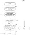
- the method 400may be implemented by the EEC 202 of FIG. 2 , i.e. by the computing device 300 of FIG. 3 .
- the method 400comprises, at step 402 , causing fuel injection into the combustor (reference 16 in FIG. 1 ) in order to achieve light-off.
- step 402may comprise the EEC 202 outputting to the fuel control unit (reference 204 in FIG. 2 ) control signal(s) comprising instructions to cause the fuel control unit to inject the fuel flow to the combustor, according to a given fuel schedule.
- One or more schedulesmay be stored in memory (reference 304 in FIG.
- the EEC 202illustratively queries the memory to select the fuel schedule that is appropriate for light-off.
- the appropriate fuel schedulefollows an open loop fuel flow profile.
- the fuel scheduleillustratively defines a minimum fuel flow limit and a maximum fuel flow limit, the minimum and maximum fuel flow limit each set at an initial value also stored in the memory.
- the minimum and maximum fuel flow limitsillustratively correspond to an amount of fuel injected into the combustor 16 .
- one or more engine operating parametersare monitored at step 404 to detect engine flameout.
- the one or more operating parametersare monitored with the engine 10 operating in the closed loop sub-idle acceleration scheduling.
- the acceleration of the engine 10is monitored at step 404 .
- the engine operating parameter(s) monitored at step 404may also include, but are not limited to, inter-stage turbine temperature.
- An assessment as to whether engine flameout, whether partial or complete, is detectedis then made at step 406 , based on the engine operating parameter(s) monitored at step 404 .
- step 406may comprise comparing the acceleration to a threshold value. If it is determined that the acceleration is below the threshold value, partial flameout is detected.
- the method 400may end. Otherwise, if engine flameout is detected at step 406 , the next step 408 is to adjust the open loop fuel schedule by increasing fuel flow injection by a predetermined amount.
- the predetermined amount of fuel injection increasemay vary depending on engine configuration (e.g., depending on factors including, but not limited to, gas generator speed, altitude, temperature, and number of partial flameouts detected during engine start).
- the initial value of the minimum fuel flow limit associated with the open loop fuel scheduleis increased by the predetermined amount so as to set the minimum fuel flow limit at a first adjusted value, which is lower than the maximum fuel flow limit.
- a first adjusted fuel scheduleis thus obtained.
- the EEC 202may then output one or more control signals to cause fuel flow to be injected into the combustor, e.g., when the engine restarts, according to the first adjusted fuel schedule.
- next step 410is to cause fuel flow injection into the combustor.
- the engine 10may be recovered from flameout.
- Steps 404 to 410are then repeated and engine parameter(s) are monitored again at step 404 to detect any subsequent engine flameout (step 406 ). If it is determined at step 406 that no subsequent engine flameout has been detected, the method 400 may end. Otherwise, the fuel injection is increased again at step 408 , by a same or different amount as previously and up to a pre-determined limit. For this purpose, the value of the minimum fuel flow limit is increased from the first adjusted value to a second adjusted value lower than the maximum fuel flow limit.
- a second adjusted fuel scheduleis thus obtained and the EEC 202 may then output one or more control signals to cause fuel flow to be injected into the combustor, e.g., when the engine restarts, according to the second adjusted fuel schedule.
- the method 400may then proceed again to step 410 .
- the process of adjusting the open loop fuel schedulee.g., steps 404 to 408
- FIG. 5shows a plot 500 illustrating fuel flow (represented by curve 502 ) and gas generator (i.e. engine) acceleration (represented by curve 504 ) as a function of gas generator (i.e. engine) speed.
- Fuel flowis injected (following an open loop fuel flow profile) at a varying rate into the combustor to reach light-off.
- Engine accelerationis continuously monitored and compared to a threshold 506 . When the engine acceleration drops below the threshold (as seen, for example, at point A 1 ), partial flameout is detected.
- the open loop fuel flow injectionis then increased (see, for example, at point B) by adjusting the minimum fuel flow limit to a higher value.
- the engine accelerationaccordingly increases above the threshold 506 .
- the open loop fuel flow injectionwould be increased once more.
- a pre-determined limite.g. the maximum fuel flow limit or the maximum number of fuel flow increases is reached. In this manner, it may be possible to limit the number of flameout occurrences during engine start.
Landscapes
- Engineering & Computer Science (AREA)
- Chemical & Material Sciences (AREA)
- Combustion & Propulsion (AREA)
- Mechanical Engineering (AREA)
- General Engineering & Computer Science (AREA)
- Combined Controls Of Internal Combustion Engines (AREA)
- Control Of Turbines (AREA)
- Electrical Control Of Air Or Fuel Supplied To Internal-Combustion Engine (AREA)
Abstract
Description
Claims (19)
Priority Applications (4)
| Application Number | Priority Date | Filing Date | Title |
|---|---|---|---|
| US16/184,297US11300054B2 (en) | 2018-11-08 | 2018-11-08 | Fuel flow control system and method for engine start |
| CA3058170ACA3058170A1 (en) | 2018-11-08 | 2019-10-08 | Fuel flow control system and method for engine start |
| ES19207548TES2909405T3 (en) | 2018-11-08 | 2019-11-06 | Fuel flow control system and method of starting an engine |
| EP19207548.9AEP3650676B1 (en) | 2018-11-08 | 2019-11-06 | Fuel flow control system and method for engine start |
Applications Claiming Priority (1)
| Application Number | Priority Date | Filing Date | Title |
|---|---|---|---|
| US16/184,297US11300054B2 (en) | 2018-11-08 | 2018-11-08 | Fuel flow control system and method for engine start |
Publications (2)
| Publication Number | Publication Date |
|---|---|
| US20200149479A1 US20200149479A1 (en) | 2020-05-14 |
| US11300054B2true US11300054B2 (en) | 2022-04-12 |
Family
ID=68470445
Family Applications (1)
| Application Number | Title | Priority Date | Filing Date |
|---|---|---|---|
| US16/184,297Active2040-02-18US11300054B2 (en) | 2018-11-08 | 2018-11-08 | Fuel flow control system and method for engine start |
Country Status (4)
| Country | Link |
|---|---|
| US (1) | US11300054B2 (en) |
| EP (1) | EP3650676B1 (en) |
| CA (1) | CA3058170A1 (en) |
| ES (1) | ES2909405T3 (en) |
Cited By (1)
| Publication number | Priority date | Publication date | Assignee | Title |
|---|---|---|---|---|
| US12398678B2 (en) | 2023-07-28 | 2025-08-26 | Rolls-Royce Corporation | Motor and motor controller thermal management features |
Families Citing this family (29)
| Publication number | Priority date | Publication date | Assignee | Title |
|---|---|---|---|---|
| US11643981B2 (en) | 2021-08-30 | 2023-05-09 | Pratt & Whitney Canada Corp. | System and method for controlling fuel flow to an aircraft engine during start |
| US12202616B2 (en) | 2021-11-04 | 2025-01-21 | General Electric Company | Relight of a propulsion system with a fuel cell |
| US11933216B2 (en) | 2022-01-04 | 2024-03-19 | General Electric Company | Systems and methods for providing output products to a combustion chamber of a gas turbine engine |
| US11719441B2 (en) | 2022-01-04 | 2023-08-08 | General Electric Company | Systems and methods for providing output products to a combustion chamber of a gas turbine engine |
| US11794912B2 (en) | 2022-01-04 | 2023-10-24 | General Electric Company | Systems and methods for reducing emissions with a fuel cell |
| US12123361B2 (en) | 2022-01-04 | 2024-10-22 | General Electric Company | Systems and methods for providing output products to a combustion chamber of a gas turbine engine |
| US12037952B2 (en) | 2022-01-04 | 2024-07-16 | General Electric Company | Systems and methods for providing output products to a combustion chamber of a gas turbine engine |
| US11970282B2 (en) | 2022-01-05 | 2024-04-30 | General Electric Company | Aircraft thrust management with a fuel cell |
| US12034298B2 (en) | 2022-01-10 | 2024-07-09 | General Electric Company | Power source for an aircraft |
| US12037124B2 (en) | 2022-01-21 | 2024-07-16 | General Electric Company | Systems and method of operating a fuel cell assembly |
| US12351329B2 (en) | 2022-01-21 | 2025-07-08 | General Electric Company | Systems and method of operating a fuel cell assembly |
| US11804607B2 (en) | 2022-01-21 | 2023-10-31 | General Electric Company | Cooling of a fuel cell assembly |
| US12074350B2 (en) | 2022-01-21 | 2024-08-27 | General Electric Company | Solid oxide fuel cell assembly |
| US11967743B2 (en) | 2022-02-21 | 2024-04-23 | General Electric Company | Modular fuel cell assembly |
| US12129789B2 (en) | 2022-02-21 | 2024-10-29 | General Electric Company | Systems and method of operating a fuel cell assembly, a gas turbine engine, or both |
| US12170390B2 (en) | 2022-02-21 | 2024-12-17 | General Electric Company | Systems and method of operating a fuel cell assembly, a gas turbine engine, or both |
| US12025061B2 (en) | 2022-04-04 | 2024-07-02 | General Electric Company | Gas turbine engine with fuel cell assembly |
| CN114837822B (en)* | 2022-04-29 | 2023-11-28 | 中国航发沈阳发动机研究所 | Self-adaptive adjustment method and system for initial oil supply amount of ground start of engine |
| US12428164B2 (en) | 2022-05-16 | 2025-09-30 | General Electric Company | Environmental control system having a fuel cell assembly |
| US12412914B2 (en) | 2022-05-16 | 2025-09-09 | General Electric Company | Environmental control system having a fuel cell assembly |
| US12043406B2 (en) | 2022-05-27 | 2024-07-23 | General Electric Company | Method of operating a fuel cell assembly for an aircraft |
| US11817700B1 (en) | 2022-07-20 | 2023-11-14 | General Electric Company | Decentralized electrical power allocation system |
| US12301002B2 (en) | 2022-08-26 | 2025-05-13 | General Electric Company | Power dispatch control system for multiple power generation sources |
| US12240613B2 (en) | 2022-11-10 | 2025-03-04 | General Electric Company | Gas turbine combustion section having an integrated fuel cell assembly |
| US11859820B1 (en) | 2022-11-10 | 2024-01-02 | General Electric Company | Gas turbine combustion section having an integrated fuel cell assembly |
| US12078350B2 (en) | 2022-11-10 | 2024-09-03 | General Electric Company | Gas turbine combustion section having an integrated fuel cell assembly |
| US11923586B1 (en) | 2022-11-10 | 2024-03-05 | General Electric Company | Gas turbine combustion section having an integrated fuel cell assembly |
| CN118532265A (en) | 2023-02-23 | 2024-08-23 | 通用电气公司 | Gas turbine engine and fuel cell assembly |
| CN118532263A (en) | 2023-02-23 | 2024-08-23 | 通用电气公司 | Gas turbine engine and fuel cell assembly |
Citations (12)
| Publication number | Priority date | Publication date | Assignee | Title |
|---|---|---|---|---|
| US3520133A (en)* | 1968-03-14 | 1970-07-14 | Gen Electric | Gas turbine control system |
| US5121597A (en)* | 1989-02-03 | 1992-06-16 | Hitachi, Ltd. | Gas turbine combustor and methodd of operating the same |
| US5129221A (en)* | 1989-05-23 | 1992-07-14 | Rolls-Royce Plc | Gas turbine engine fuel control system with enhanced relight capability |
| US5212943A (en) | 1991-10-08 | 1993-05-25 | Sundstrand Corporation | Reduced thermal stress turbine starting strategy |
| US5303541A (en) | 1991-10-11 | 1994-04-19 | Alliedsignal Inc. | Closed loop fuel control method |
| US5551227A (en)* | 1994-12-22 | 1996-09-03 | General Electric Company | System and method of detecting partial flame out in a gas turbine engine combustor |
| US6516263B1 (en)* | 2001-08-02 | 2003-02-04 | Honeywell Power Systems Inc. | Adaptive flame-out prevention |
| US20040200206A1 (en) | 2002-03-20 | 2004-10-14 | Mckelvey Terrence | Gas turbine apparatus |
| US7168254B2 (en) | 2004-02-17 | 2007-01-30 | Honeywell International Inc. | Control logic for fuel controls on APUs |
| US20140095051A1 (en)* | 2012-09-28 | 2014-04-03 | Pratt & Whitney Canada Corp. | Adaptive fuel manifold filling function for improved engine start |
| US8915088B2 (en) | 2010-06-11 | 2014-12-23 | Hamilton Sundstrand Corporation | Fuel control method for starting a gas turbine engine |
| US20180258863A1 (en)* | 2017-03-08 | 2018-09-13 | General Electric Company | System and method for adjusting combustor fuel split |
- 2018
- 2018-11-08USUS16/184,297patent/US11300054B2/enactiveActive
- 2019
- 2019-10-08CACA3058170Apatent/CA3058170A1/enactivePending
- 2019-11-06EPEP19207548.9Apatent/EP3650676B1/enactiveActive
- 2019-11-06ESES19207548Tpatent/ES2909405T3/enactiveActive
Patent Citations (13)
| Publication number | Priority date | Publication date | Assignee | Title |
|---|---|---|---|---|
| US3520133A (en)* | 1968-03-14 | 1970-07-14 | Gen Electric | Gas turbine control system |
| US5121597A (en)* | 1989-02-03 | 1992-06-16 | Hitachi, Ltd. | Gas turbine combustor and methodd of operating the same |
| US5129221A (en)* | 1989-05-23 | 1992-07-14 | Rolls-Royce Plc | Gas turbine engine fuel control system with enhanced relight capability |
| US5212943A (en) | 1991-10-08 | 1993-05-25 | Sundstrand Corporation | Reduced thermal stress turbine starting strategy |
| US5303541A (en) | 1991-10-11 | 1994-04-19 | Alliedsignal Inc. | Closed loop fuel control method |
| US5551227A (en)* | 1994-12-22 | 1996-09-03 | General Electric Company | System and method of detecting partial flame out in a gas turbine engine combustor |
| US6516263B1 (en)* | 2001-08-02 | 2003-02-04 | Honeywell Power Systems Inc. | Adaptive flame-out prevention |
| US20040200206A1 (en) | 2002-03-20 | 2004-10-14 | Mckelvey Terrence | Gas turbine apparatus |
| US6978597B2 (en) | 2002-03-20 | 2005-12-27 | Ebara Corporation | Flame detecting apparatus for gas turbine |
| US7168254B2 (en) | 2004-02-17 | 2007-01-30 | Honeywell International Inc. | Control logic for fuel controls on APUs |
| US8915088B2 (en) | 2010-06-11 | 2014-12-23 | Hamilton Sundstrand Corporation | Fuel control method for starting a gas turbine engine |
| US20140095051A1 (en)* | 2012-09-28 | 2014-04-03 | Pratt & Whitney Canada Corp. | Adaptive fuel manifold filling function for improved engine start |
| US20180258863A1 (en)* | 2017-03-08 | 2018-09-13 | General Electric Company | System and method for adjusting combustor fuel split |
Cited By (1)
| Publication number | Priority date | Publication date | Assignee | Title |
|---|---|---|---|---|
| US12398678B2 (en) | 2023-07-28 | 2025-08-26 | Rolls-Royce Corporation | Motor and motor controller thermal management features |
Also Published As
| Publication number | Publication date |
|---|---|
| ES2909405T3 (en) | 2022-05-06 |
| EP3650676B1 (en) | 2021-12-29 |
| US20200149479A1 (en) | 2020-05-14 |
| EP3650676A1 (en) | 2020-05-13 |
| CA3058170A1 (en) | 2020-05-08 |
Similar Documents
| Publication | Publication Date | Title |
|---|---|---|
| US11300054B2 (en) | Fuel flow control system and method for engine start | |
| JP4118811B2 (en) | Gas turbine engine starting method | |
| US3902315A (en) | Starting fuel control system for gas turbine engines | |
| JP6633960B2 (en) | Ignition detection device for aircraft gas turbine engine | |
| US11131211B2 (en) | Method and system for setting an acceleration schedule for engine start | |
| RU2316663C1 (en) | Method of metering out of fuel at starting of gas-turbine engine | |
| US11859555B2 (en) | Systems and methods for starting a gas turbine engine | |
| RU2594843C2 (en) | Method for gas turbine engine start-up | |
| JP6633962B2 (en) | Aircraft gas turbine engine controller | |
| EP4141238A1 (en) | System and method for controlling fuel flow to an aircraft engine during start | |
| US11506076B2 (en) | Methods and systems for starting an engine | |
| RU2753434C1 (en) | Method for starting a single-shaft single-mode gas turbine engine | |
| CN110886656A (en) | Method and system for setting acceleration schedule for engine start | |
| EP4036391B1 (en) | Methods and systems for detecting and responding to an engine disturbance | |
| RU2773081C2 (en) | Method for determination of ignition of gas turbine engine | |
| JPS6125896B2 (en) |
Legal Events
| Date | Code | Title | Description |
|---|---|---|---|
| FEPP | Fee payment procedure | Free format text:ENTITY STATUS SET TO UNDISCOUNTED (ORIGINAL EVENT CODE: BIG.); ENTITY STATUS OF PATENT OWNER: SMALL ENTITY | |
| FEPP | Fee payment procedure | Free format text:ENTITY STATUS SET TO SMALL (ORIGINAL EVENT CODE: SMAL); ENTITY STATUS OF PATENT OWNER: SMALL ENTITY Free format text:ENTITY STATUS SET TO UNDISCOUNTED (ORIGINAL EVENT CODE: BIG.); ENTITY STATUS OF PATENT OWNER: SMALL ENTITY | |
| STPP | Information on status: patent application and granting procedure in general | Free format text:NON FINAL ACTION MAILED | |
| STPP | Information on status: patent application and granting procedure in general | Free format text:RESPONSE TO NON-FINAL OFFICE ACTION ENTERED AND FORWARDED TO EXAMINER | |
| STPP | Information on status: patent application and granting procedure in general | Free format text:FINAL REJECTION MAILED | |
| STPP | Information on status: patent application and granting procedure in general | Free format text:RESPONSE AFTER FINAL ACTION FORWARDED TO EXAMINER | |
| STPP | Information on status: patent application and granting procedure in general | Free format text:ADVISORY ACTION MAILED | |
| STPP | Information on status: patent application and granting procedure in general | Free format text:DOCKETED NEW CASE - READY FOR EXAMINATION | |
| STPP | Information on status: patent application and granting procedure in general | Free format text:NOTICE OF ALLOWANCE MAILED -- APPLICATION RECEIVED IN OFFICE OF PUBLICATIONS | |
| STPP | Information on status: patent application and granting procedure in general | Free format text:PUBLICATIONS -- ISSUE FEE PAYMENT VERIFIED | |
| STCF | Information on status: patent grant | Free format text:PATENTED CASE | |
| MAFP | Maintenance fee payment | Free format text:PAYMENT OF MAINTENANCE FEE, 4TH YR, SMALL ENTITY (ORIGINAL EVENT CODE: M2551); ENTITY STATUS OF PATENT OWNER: SMALL ENTITY Year of fee payment:4 |