US11299705B2 - System and method for creating tissue - Google Patents
System and method for creating tissueDownload PDFInfo
- Publication number
- US11299705B2 US11299705B2US15/805,790US201715805790AUS11299705B2US 11299705 B2US11299705 B2US 11299705B2US 201715805790 AUS201715805790 AUS 201715805790AUS 11299705 B2US11299705 B2US 11299705B2
- Authority
- US
- United States
- Prior art keywords
- tissue
- subsystem
- fluid
- commands
- chamber
- Prior art date
- Legal status (The legal status is an assumption and is not a legal conclusion. Google has not performed a legal analysis and makes no representation as to the accuracy of the status listed.)
- Active, expires
Links
- 238000000034methodMethods0.000titleabstractdescription137
- 108090000623proteins and genesProteins0.000claimsabstractdescription98
- 102000004169proteins and genesHuman genes0.000claimsabstractdescription98
- 239000001963growth mediumSubstances0.000claimsabstractdescription94
- 238000007639printingMethods0.000claimsabstractdescription78
- 239000000203mixtureSubstances0.000claimsabstractdescription39
- 230000035899viabilityEffects0.000claimsabstractdescription33
- 239000012530fluidSubstances0.000claimsdescription381
- 239000000463materialSubstances0.000claimsdescription165
- 238000001914filtrationMethods0.000claimsdescription90
- 239000002699waste materialSubstances0.000claimsdescription64
- 239000003085diluting agentSubstances0.000claimsdescription48
- 210000000056organAnatomy0.000claimsdescription43
- 238000005086pumpingMethods0.000claimsdescription38
- 238000012544monitoring processMethods0.000claimsdescription37
- 239000000047productSubstances0.000claimsdescription35
- 238000004891communicationMethods0.000claimsdescription33
- 238000012423maintenanceMethods0.000claimsdescription29
- 239000000835fiberSubstances0.000claimsdescription26
- 239000011148porous materialSubstances0.000claimsdescription26
- 239000013589supplementSubstances0.000claimsdescription19
- NIXOWILDQLNWCW-UHFFFAOYSA-NAcrylic acidChemical compoundOC(=O)C=CNIXOWILDQLNWCW-UHFFFAOYSA-N0.000claimsdescription15
- 229920002125Sokalan®Polymers0.000claimsdescription15
- 229960001631carbomerDrugs0.000claimsdescription15
- 230000008878couplingEffects0.000claimsdescription14
- 238000010168coupling processMethods0.000claimsdescription14
- 238000005859coupling reactionMethods0.000claimsdescription14
- 230000004060metabolic processEffects0.000claimsdescription14
- 239000007640basal mediumSubstances0.000claimsdescription10
- 230000033001locomotionEffects0.000claimsdescription9
- 239000013603viral vectorSubstances0.000claimsdescription7
- 230000035764nutritionEffects0.000claimsdescription6
- 235000016709nutritionNutrition0.000claimsdescription6
- 230000004044responseEffects0.000claimsdescription6
- 239000012620biological materialSubstances0.000abstractdescription64
- 230000008467tissue growthEffects0.000abstractdescription22
- 210000001519tissueAnatomy0.000description579
- 210000004027cellAnatomy0.000description190
- 239000000499gelSubstances0.000description118
- 238000002156mixingMethods0.000description76
- 239000000976inkSubstances0.000description71
- 230000008569processEffects0.000description68
- 239000003570airSubstances0.000description50
- 239000002609mediumSubstances0.000description45
- 239000000243solutionSubstances0.000description42
- CURLTUGMZLYLDI-UHFFFAOYSA-NCarbon dioxideChemical compoundO=C=OCURLTUGMZLYLDI-UHFFFAOYSA-N0.000description29
- 230000012010growthEffects0.000description28
- 230000037361pathwayEffects0.000description26
- 125000006850spacer groupChemical group0.000description26
- 238000003860storageMethods0.000description26
- 230000010261cell growthEffects0.000description25
- 210000004072lungAnatomy0.000description24
- 238000007789sealingMethods0.000description24
- 238000010586diagramMethods0.000description23
- 210000005036nerveAnatomy0.000description21
- 235000015097nutrientsNutrition0.000description20
- 230000014616translationEffects0.000description19
- QVGXLLKOCUKJST-UHFFFAOYSA-Natomic oxygenChemical compound[O]QVGXLLKOCUKJST-UHFFFAOYSA-N0.000description18
- 238000000502dialysisMethods0.000description18
- 239000012528membraneSubstances0.000description18
- 229910052760oxygenInorganic materials0.000description18
- 239000001301oxygenSubstances0.000description18
- 230000035800maturationEffects0.000description16
- 230000003287optical effectEffects0.000description16
- 230000008093supporting effectEffects0.000description16
- 229910002092carbon dioxideInorganic materials0.000description15
- 239000001569carbon dioxideSubstances0.000description15
- 238000010438heat treatmentMethods0.000description15
- 230000000694effectsEffects0.000description13
- 229910052751metalInorganic materials0.000description13
- 239000002184metalSubstances0.000description13
- 239000007787solidSubstances0.000description13
- XLYOFNOQVPJJNP-UHFFFAOYSA-NwaterChemical compoundOXLYOFNOQVPJJNP-UHFFFAOYSA-N0.000description13
- 102000007056Recombinant Fusion ProteinsHuman genes0.000description12
- 108010008281Recombinant Fusion ProteinsProteins0.000description12
- 230000008859changeEffects0.000description12
- 239000007789gasSubstances0.000description12
- 239000012141concentrateSubstances0.000description11
- 239000002243precursorSubstances0.000description10
- 230000005855radiationEffects0.000description10
- 239000000523sampleSubstances0.000description10
- 238000012360testing methodMethods0.000description10
- 238000012546transferMethods0.000description10
- HEMHJVSKTPXQMS-UHFFFAOYSA-MSodium hydroxideChemical compound[OH-].[Na+]HEMHJVSKTPXQMS-UHFFFAOYSA-M0.000description9
- 239000012298atmosphereSubstances0.000description9
- 239000000470constituentSubstances0.000description9
- 230000001939inductive effectEffects0.000description9
- 238000011068loading methodMethods0.000description9
- 238000012384transportation and deliveryMethods0.000description9
- 230000000007visual effectEffects0.000description9
- 238000001069Raman spectroscopyMethods0.000description8
- 238000004458analytical methodMethods0.000description8
- 238000001574biopsyMethods0.000description8
- 238000009792diffusion processMethods0.000description8
- 229920006351engineering plasticPolymers0.000description8
- 239000007788liquidSubstances0.000description8
- 229910052755nonmetalInorganic materials0.000description8
- 229920000642polymerPolymers0.000description8
- 238000011282treatmentMethods0.000description8
- -1HASProteins0.000description7
- 239000003795chemical substances by applicationSubstances0.000description7
- 238000004587chromatography analysisMethods0.000description7
- 230000006378damageEffects0.000description7
- 210000003608feceAnatomy0.000description7
- 239000003102growth factorSubstances0.000description7
- 238000004519manufacturing processMethods0.000description7
- 210000002569neuronAnatomy0.000description7
- 150000003839saltsChemical class0.000description7
- 238000011144upstream manufacturingMethods0.000description7
- WQZGKKKJIJFFOK-GASJEMHNSA-NGlucoseNatural productsOC[C@H]1OC(O)[C@H](O)[C@@H](O)[C@@H]1OWQZGKKKJIJFFOK-GASJEMHNSA-N0.000description6
- 210000003050axonAnatomy0.000description6
- 238000001523electrospinningMethods0.000description6
- 238000005516engineering processMethods0.000description6
- 230000003278mimic effectEffects0.000description6
- 239000000725suspensionSubstances0.000description6
- IJGRMHOSHXDMSA-UHFFFAOYSA-NAtomic nitrogenChemical compoundN#NIJGRMHOSHXDMSA-UHFFFAOYSA-N0.000description5
- 238000003491arrayMethods0.000description5
- 238000003556assayMethods0.000description5
- 239000003153chemical reaction reagentSubstances0.000description5
- 230000006835compressionEffects0.000description5
- 238000007906compressionMethods0.000description5
- 239000003814drugSubstances0.000description5
- 238000009472formulationMethods0.000description5
- 239000008103glucoseSubstances0.000description5
- 239000000017hydrogelSubstances0.000description5
- 238000002347injectionMethods0.000description5
- 239000007924injectionSubstances0.000description5
- 239000006174pH bufferSubstances0.000description5
- 230000002572peristaltic effectEffects0.000description5
- 229920003023plasticPolymers0.000description5
- 239000004033plasticSubstances0.000description5
- 239000004417polycarbonateSubstances0.000description5
- 229920000515polycarbonatePolymers0.000description5
- 238000012545processingMethods0.000description5
- 230000003946protein processEffects0.000description5
- 238000010925quality by designMethods0.000description5
- 230000001954sterilising effectEffects0.000description5
- 239000000126substanceSubstances0.000description5
- 239000004094surface-active agentSubstances0.000description5
- 238000003325tomographyMethods0.000description5
- BHPQYMZQTOCNFJ-UHFFFAOYSA-NCalcium cationChemical compound[Ca+2]BHPQYMZQTOCNFJ-UHFFFAOYSA-N0.000description4
- CSNNHWWHGAXBCP-UHFFFAOYSA-LMagnesium sulfateChemical compound[Mg+2].[O-][S+2]([O-])([O-])[O-]CSNNHWWHGAXBCP-UHFFFAOYSA-L0.000description4
- NPYPAHLBTDXSSS-UHFFFAOYSA-NPotassium ionChemical compound[K+]NPYPAHLBTDXSSS-UHFFFAOYSA-N0.000description4
- UIIMBOGNXHQVGW-UHFFFAOYSA-MSodium bicarbonateChemical compound[Na+].OC([O-])=OUIIMBOGNXHQVGW-UHFFFAOYSA-M0.000description4
- FKNQFGJONOIPTF-UHFFFAOYSA-NSodium cationChemical compound[Na+]FKNQFGJONOIPTF-UHFFFAOYSA-N0.000description4
- 238000010521absorption reactionMethods0.000description4
- 230000009471actionEffects0.000description4
- 239000000872bufferSubstances0.000description4
- 229910001424calcium ionInorganic materials0.000description4
- 230000003833cell viabilityEffects0.000description4
- 238000010276constructionMethods0.000description4
- 238000011109contaminationMethods0.000description4
- 238000001514detection methodMethods0.000description4
- 229940079593drugDrugs0.000description4
- 230000006870functionEffects0.000description4
- 230000005484gravityEffects0.000description4
- 238000003384imaging methodMethods0.000description4
- 230000001976improved effectEffects0.000description4
- 230000003993interactionEffects0.000description4
- 230000007246mechanismEffects0.000description4
- 239000002207metaboliteSubstances0.000description4
- 230000036961partial effectEffects0.000description4
- 229910001414potassium ionInorganic materials0.000description4
- 230000037452primingEffects0.000description4
- 238000011057process analytical technologyMethods0.000description4
- 239000002096quantum dotSubstances0.000description4
- 230000002829reductive effectEffects0.000description4
- 229910001415sodium ionInorganic materials0.000description4
- 230000000638stimulationEffects0.000description4
- PEDCQBHIVMGVHV-UHFFFAOYSA-NGlycerineChemical compoundOCC(O)COPEDCQBHIVMGVHV-UHFFFAOYSA-N0.000description3
- WHUUTDBJXJRKMK-VKHMYHEASA-NL-glutamic acidChemical compoundOC(=O)[C@@H](N)CCC(O)=OWHUUTDBJXJRKMK-VKHMYHEASA-N0.000description3
- 108060001084LuciferaseProteins0.000description3
- 206010028980NeoplasmDiseases0.000description3
- 208000027418Wounds and injuryDiseases0.000description3
- 239000000654additiveSubstances0.000description3
- 230000003376axonal effectEffects0.000description3
- 230000004071biological effectEffects0.000description3
- 230000001419dependent effectEffects0.000description3
- 238000000151depositionMethods0.000description3
- 238000009826distributionMethods0.000description3
- 239000000975dyeSubstances0.000description3
- 230000007613environmental effectEffects0.000description3
- 238000011049fillingMethods0.000description3
- 229930195712glutamateNatural products0.000description3
- ZDXPYRJPNDTMRX-UHFFFAOYSA-NglutamineNatural productsOC(=O)C(N)CCC(N)=OZDXPYRJPNDTMRX-UHFFFAOYSA-N0.000description3
- 230000036541healthEffects0.000description3
- 230000002209hydrophobic effectEffects0.000description3
- 230000002706hydrostatic effectEffects0.000description3
- 239000004615ingredientSubstances0.000description3
- 208000014674injuryDiseases0.000description3
- 238000002595magnetic resonance imagingMethods0.000description3
- 238000005259measurementMethods0.000description3
- 238000000386microscopyMethods0.000description3
- 239000000178monomerSubstances0.000description3
- 210000000653nervous systemAnatomy0.000description3
- 239000002245particleSubstances0.000description3
- 230000000704physical effectEffects0.000description3
- 229920000728polyesterPolymers0.000description3
- 238000002360preparation methodMethods0.000description3
- 238000000746purificationMethods0.000description3
- 230000035945sensitivityEffects0.000description3
- 230000011664signalingEffects0.000description3
- 239000002904solventSubstances0.000description3
- 230000006641stabilisationEffects0.000description3
- 238000011105stabilizationMethods0.000description3
- 238000004659sterilization and disinfectionMethods0.000description3
- 239000000758substrateSubstances0.000description3
- CCEKAJIANROZEO-UHFFFAOYSA-NsulfluramidChemical groupCCNS(=O)(=O)C(F)(F)C(F)(F)C(F)(F)C(F)(F)C(F)(F)C(F)(F)C(F)(F)C(F)(F)FCCEKAJIANROZEO-UHFFFAOYSA-N0.000description3
- 239000012780transparent materialSubstances0.000description3
- 229940088594vitaminDrugs0.000description3
- 239000011782vitaminSubstances0.000description3
- 235000013343vitaminNutrition0.000description3
- 229930003231vitaminNatural products0.000description3
- YBJHBAHKTGYVGT-ZKWXMUAHSA-N(+)-BiotinChemical compoundN1C(=O)N[C@@H]2[C@H](CCCCC(=O)O)SC[C@@H]21YBJHBAHKTGYVGT-ZKWXMUAHSA-N0.000description2
- 2380000101463D printingMethods0.000description2
- 206010001497AgitationDiseases0.000description2
- 108010035532CollagenProteins0.000description2
- 102000008186CollagenHuman genes0.000description2
- IGXWBGJHJZYPQS-SSDOTTSWSA-ND-LuciferinChemical compoundOC(=O)[C@H]1CSC(C=2SC3=CC=C(O)C=C3N=2)=N1IGXWBGJHJZYPQS-SSDOTTSWSA-N0.000description2
- CYCGRDQQIOGCKX-UHFFFAOYSA-NDehydro-luciferinNatural productsOC(=O)C1=CSC(C=2SC3=CC(O)=CC=C3N=2)=N1CYCGRDQQIOGCKX-UHFFFAOYSA-N0.000description2
- 108090000790EnzymesProteins0.000description2
- 102000004190EnzymesHuman genes0.000description2
- LFQSCWFLJHTTHZ-UHFFFAOYSA-NEthanolChemical compoundCCOLFQSCWFLJHTTHZ-UHFFFAOYSA-N0.000description2
- IAYPIBMASNFSPL-UHFFFAOYSA-NEthylene oxideChemical compoundC1CO1IAYPIBMASNFSPL-UHFFFAOYSA-N0.000description2
- BJGNCJDXODQBOB-UHFFFAOYSA-NFivefly LuciferinNatural productsOC(=O)C1CSC(C=2SC3=CC(O)=CC=C3N=2)=N1BJGNCJDXODQBOB-UHFFFAOYSA-N0.000description2
- JVTAAEKCZFNVCJ-UHFFFAOYSA-MLactateChemical compoundCC(O)C([O-])=OJVTAAEKCZFNVCJ-UHFFFAOYSA-M0.000description2
- 239000005089LuciferaseSubstances0.000description2
- DDWFXDSYGUXRAY-UHFFFAOYSA-NLuciferinNatural productsCCc1c(C)c(CC2NC(=O)C(=C2C=C)C)[nH]c1Cc3[nH]c4C(=C5/NC(CC(=O)O)C(C)C5CC(=O)O)CC(=O)c4c3CDDWFXDSYGUXRAY-UHFFFAOYSA-N0.000description2
- 102000018697Membrane ProteinsHuman genes0.000description2
- 108010052285Membrane ProteinsProteins0.000description2
- 239000002033PVDF binderSubstances0.000description2
- 239000004743PolypropyleneSubstances0.000description2
- AUNGANRZJHBGPY-SCRDCRAPSA-NRiboflavinChemical compoundOC[C@@H](O)[C@@H](O)[C@@H](O)CN1C=2C=C(C)C(C)=CC=2N=C2C1=NC(=O)NC2=OAUNGANRZJHBGPY-SCRDCRAPSA-N0.000description2
- RTAQQCXQSZGOHL-UHFFFAOYSA-NTitaniumChemical compound[Ti]RTAQQCXQSZGOHL-UHFFFAOYSA-N0.000description2
- 230000004308accommodationEffects0.000description2
- 239000000853adhesiveSubstances0.000description2
- 230000001070adhesive effectEffects0.000description2
- 150000001413amino acidsChemical class0.000description2
- 238000013459approachMethods0.000description2
- 230000003190augmentative effectEffects0.000description2
- 239000011324beadSubstances0.000description2
- 230000008901benefitEffects0.000description2
- WQZGKKKJIJFFOK-VFUOTHLCSA-Nbeta-D-glucoseChemical compoundOC[C@H]1O[C@@H](O)[C@H](O)[C@@H](O)[C@@H]1OWQZGKKKJIJFFOK-VFUOTHLCSA-N0.000description2
- 230000029918bioluminescenceEffects0.000description2
- 238000005415bioluminescenceMethods0.000description2
- 239000006172buffering agentSubstances0.000description2
- 201000011510cancerDiseases0.000description2
- 230000024245cell differentiationEffects0.000description2
- 230000006727cell lossEffects0.000description2
- 230000001413cellular effectEffects0.000description2
- 210000003850cellular structureAnatomy0.000description2
- 229920001436collagenPolymers0.000description2
- 239000004035construction materialSubstances0.000description2
- 239000000356contaminantSubstances0.000description2
- 238000012864cross contaminationMethods0.000description2
- 238000005520cutting processMethods0.000description2
- 230000003247decreasing effectEffects0.000description2
- 239000008367deionised waterSubstances0.000description2
- 230000008021depositionEffects0.000description2
- 230000000994depressogenic effectEffects0.000description2
- 238000007599dischargingMethods0.000description2
- 230000002708enhancing effectEffects0.000description2
- 230000005284excitationEffects0.000description2
- 238000001125extrusionMethods0.000description2
- OVBPIULPVIDEAO-LBPRGKRZSA-Nfolic acidChemical compoundC=1N=C2NC(N)=NC(=O)C2=NC=1CNC1=CC=C(C(=O)N[C@@H](CCC(O)=O)C(O)=O)C=C1OVBPIULPVIDEAO-LBPRGKRZSA-N0.000description2
- 230000013632homeostatic processEffects0.000description2
- 238000005286illuminationMethods0.000description2
- 238000011065in-situ storageMethods0.000description2
- 230000036512infertilityEffects0.000description2
- NOESYZHRGYRDHS-UHFFFAOYSA-NinsulinChemical compoundN1C(=O)C(NC(=O)C(CCC(N)=O)NC(=O)C(CCC(O)=O)NC(=O)C(C(C)C)NC(=O)C(NC(=O)CN)C(C)CC)CSSCC(C(NC(CO)C(=O)NC(CC(C)C)C(=O)NC(CC=2C=CC(O)=CC=2)C(=O)NC(CCC(N)=O)C(=O)NC(CC(C)C)C(=O)NC(CCC(O)=O)C(=O)NC(CC(N)=O)C(=O)NC(CC=2C=CC(O)=CC=2)C(=O)NC(CSSCC(NC(=O)C(C(C)C)NC(=O)C(CC(C)C)NC(=O)C(CC=2C=CC(O)=CC=2)NC(=O)C(CC(C)C)NC(=O)C(C)NC(=O)C(CCC(O)=O)NC(=O)C(C(C)C)NC(=O)C(CC(C)C)NC(=O)C(CC=2NC=NC=2)NC(=O)C(CO)NC(=O)CNC2=O)C(=O)NCC(=O)NC(CCC(O)=O)C(=O)NC(CCCNC(N)=N)C(=O)NCC(=O)NC(CC=3C=CC=CC=3)C(=O)NC(CC=3C=CC=CC=3)C(=O)NC(CC=3C=CC(O)=CC=3)C(=O)NC(C(C)O)C(=O)N3C(CCC3)C(=O)NC(CCCCN)C(=O)NC(C)C(O)=O)C(=O)NC(CC(N)=O)C(O)=O)=O)NC(=O)C(C(C)CC)NC(=O)C(CO)NC(=O)C(C(C)O)NC(=O)C1CSSCC2NC(=O)C(CC(C)C)NC(=O)C(NC(=O)C(CCC(N)=O)NC(=O)C(CC(N)=O)NC(=O)C(NC(=O)C(N)CC=1C=CC=CC=1)C(C)C)CC1=CN=CN1NOESYZHRGYRDHS-UHFFFAOYSA-N0.000description2
- 230000010354integrationEffects0.000description2
- 150000002500ionsChemical class0.000description2
- 229910052943magnesium sulfateInorganic materials0.000description2
- 235000019341magnesium sulphateNutrition0.000description2
- 238000007726management methodMethods0.000description2
- 239000012092media componentSubstances0.000description2
- 230000002503metabolic effectEffects0.000description2
- 238000012986modificationMethods0.000description2
- 230000004048modificationEffects0.000description2
- 238000012806monitoring deviceMethods0.000description2
- 230000003472neutralizing effectEffects0.000description2
- 210000002445nippleAnatomy0.000description2
- 229910052757nitrogenInorganic materials0.000description2
- 239000003921oilSubstances0.000description2
- 238000006213oxygenation reactionMethods0.000description2
- 230000010412perfusionEffects0.000description2
- 229920001296polysiloxanePolymers0.000description2
- 229920002981polyvinylidene fluoridePolymers0.000description2
- 210000001147pulmonary arteryAnatomy0.000description2
- 238000004064recyclingMethods0.000description2
- 230000003014reinforcing effectEffects0.000description2
- 238000012429release testingMethods0.000description2
- 238000001223reverse osmosisMethods0.000description2
- 238000005070samplingMethods0.000description2
- 238000007790scrapingMethods0.000description2
- 235000017557sodium bicarbonateNutrition0.000description2
- 229910000030sodium bicarbonateInorganic materials0.000description2
- BBMHARZCALWXSL-UHFFFAOYSA-Msodium dihydrogenphosphate monohydrateChemical compoundO.[Na+].OP(O)([O-])=OBBMHARZCALWXSL-UHFFFAOYSA-M0.000description2
- 238000001228spectrumMethods0.000description2
- 230000002269spontaneous effectEffects0.000description2
- 230000003068static effectEffects0.000description2
- 210000000130stem cellAnatomy0.000description2
- 239000010936titaniumSubstances0.000description2
- 229910052719titaniumInorganic materials0.000description2
- 210000003437tracheaAnatomy0.000description2
- 230000007704transitionEffects0.000description2
- 238000002054transplantationMethods0.000description2
- 229920001862ultra low molecular weight polyethylenePolymers0.000description2
- 2390000017632-hydroxyethyl(trimethyl)azaniumSubstances0.000description1
- GUBGYTABKSRVRQ-XLOQQCSPSA-NAlpha-LactoseChemical compoundO[C@@H]1[C@@H](O)[C@@H](O)[C@@H](CO)O[C@H]1O[C@@H]1[C@@H](CO)O[C@H](O)[C@H](O)[C@H]1OGUBGYTABKSRVRQ-XLOQQCSPSA-N0.000description1
- QGZKDVFQNNGYKY-UHFFFAOYSA-OAmmoniumChemical compound[NH4+]QGZKDVFQNNGYKY-UHFFFAOYSA-O0.000description1
- 102000016904Armadillo Domain ProteinsHuman genes0.000description1
- 108010014223Armadillo Domain ProteinsProteins0.000description1
- NVMMUAUTQCWYHD-ABHRYQDASA-NAsp-Val-Pro-ProChemical compoundOC(=O)C[C@H](N)C(=O)N[C@@H](C(C)C)C(=O)N1CCC[C@H]1C(=O)N1[C@H](C(O)=O)CCC1NVMMUAUTQCWYHD-ABHRYQDASA-N0.000description1
- OYPRJOBELJOOCE-UHFFFAOYSA-NCalciumChemical compound[Ca]OYPRJOBELJOOCE-UHFFFAOYSA-N0.000description1
- 235000019743Choline chlorideNutrition0.000description1
- AUNGANRZJHBGPY-UHFFFAOYSA-ND-LyxoflavinNatural productsOCC(O)C(O)C(O)CN1C=2C=C(C)C(C)=CC=2N=C2C1=NC(=O)NC2=OAUNGANRZJHBGPY-UHFFFAOYSA-N0.000description1
- 241000289632DasypodidaeSpecies0.000description1
- JOYRKODLDBILNP-UHFFFAOYSA-NEthyl urethaneChemical compoundCCOC(N)=OJOYRKODLDBILNP-UHFFFAOYSA-N0.000description1
- 108010037362Extracellular Matrix ProteinsProteins0.000description1
- 102000010834Extracellular Matrix ProteinsHuman genes0.000description1
- 101150021185FGF geneProteins0.000description1
- 108010073385FibrinProteins0.000description1
- 102000009123FibrinHuman genes0.000description1
- BWGVNKXGVNDBDI-UHFFFAOYSA-NFibrin monomerChemical compoundCNC(=O)CNC(=O)CNBWGVNKXGVNDBDI-UHFFFAOYSA-N0.000description1
- 108090000386Fibroblast Growth Factor 1Proteins0.000description1
- 102100031706Fibroblast growth factor 1Human genes0.000description1
- 108010067306FibronectinsProteins0.000description1
- 102000016359FibronectinsHuman genes0.000description1
- 101001066435Homo sapiens Hepatocyte growth factor-like proteinProteins0.000description1
- 101000880439Homo sapiens Serine/threonine-protein kinase 3Proteins0.000description1
- 101000880431Homo sapiens Serine/threonine-protein kinase 4Proteins0.000description1
- 101000759453Homo sapiens YY1-associated protein 1Proteins0.000description1
- DGAQECJNVWCQMB-PUAWFVPOSA-MIlexoside XXIXChemical compoundC[C@@H]1CC[C@@]2(CC[C@@]3(C(=CC[C@H]4[C@]3(CC[C@@H]5[C@@]4(CC[C@@H](C5(C)C)OS(=O)(=O)[O-])C)C)[C@@H]2[C@]1(C)O)C)C(=O)O[C@H]6[C@@H]([C@H]([C@@H]([C@H](O6)CO)O)O)O.[Na+]DGAQECJNVWCQMB-PUAWFVPOSA-M0.000description1
- 102000004877InsulinHuman genes0.000description1
- 108090001061InsulinProteins0.000description1
- ZDXPYRJPNDTMRX-VKHMYHEASA-NL-glutamineChemical compoundOC(=O)[C@@H](N)CCC(N)=OZDXPYRJPNDTMRX-VKHMYHEASA-N0.000description1
- GUBGYTABKSRVRQ-QKKXKWKRSA-NLactoseNatural productsOC[C@H]1O[C@@H](O[C@H]2[C@H](O)[C@@H](O)C(O)O[C@@H]2CO)[C@H](O)[C@@H](O)[C@H]1OGUBGYTABKSRVRQ-QKKXKWKRSA-N0.000description1
- 102000007547LamininHuman genes0.000description1
- 108010085895LamininProteins0.000description1
- 108090001030LipoproteinsProteins0.000description1
- 102000004895LipoproteinsHuman genes0.000description1
- 102100034502Lysosomal thioesterase PPT2Human genes0.000description1
- 108050001602Lysosomal thioesterase PPT2Proteins0.000description1
- 241001465754MetazoaSpecies0.000description1
- OVBPIULPVIDEAO-UHFFFAOYSA-NN-Pteroyl-L-glutaminsaeureNatural productsC=1N=C2NC(N)=NC(=O)C2=NC=1CNC1=CC=C(C(=O)NC(CCC(O)=O)C(O)=O)C=C1OVBPIULPVIDEAO-UHFFFAOYSA-N0.000description1
- 102000009913Peroxisomal Targeting Signal 2 ReceptorHuman genes0.000description1
- 108010077056Peroxisomal Targeting Signal 2 ReceptorProteins0.000description1
- 239000004695Polyether sulfoneSubstances0.000description1
- ZLMJMSJWJFRBEC-UHFFFAOYSA-NPotassiumChemical compound[K]ZLMJMSJWJFRBEC-UHFFFAOYSA-N0.000description1
- LCTONWCANYUPML-UHFFFAOYSA-MPyruvateChemical compoundCC(=O)C([O-])=OLCTONWCANYUPML-UHFFFAOYSA-M0.000description1
- 108700008625Reporter GenesProteins0.000description1
- 102100037628Serine/threonine-protein kinase 3Human genes0.000description1
- 102100037629Serine/threonine-protein kinase 4Human genes0.000description1
- 102100026508TafazzinHuman genes0.000description1
- 101710175789TafazzinProteins0.000description1
- ATJFFYVFTNAWJD-UHFFFAOYSA-NTinChemical compound[Sn]ATJFFYVFTNAWJD-UHFFFAOYSA-N0.000description1
- 102000004338TransferrinHuman genes0.000description1
- 108090000901TransferrinProteins0.000description1
- 102000004142TrypsinHuman genes0.000description1
- 108090000631TrypsinProteins0.000description1
- 108010019530Vascular Endothelial Growth FactorsProteins0.000description1
- 102000005789Vascular Endothelial Growth FactorsHuman genes0.000description1
- 108010031318VitronectinProteins0.000description1
- 102100035140VitronectinHuman genes0.000description1
- 238000002441X-ray diffractionMethods0.000description1
- 102100023267YY1-associated protein 1Human genes0.000description1
- DFPAKSUCGFBDDF-ZQBYOMGUSA-N[14c]-nicotinamideChemical compoundN[14C](=O)C1=CC=CN=C1DFPAKSUCGFBDDF-ZQBYOMGUSA-N0.000description1
- 238000000862absorption spectrumMethods0.000description1
- 230000004913activationEffects0.000description1
- 230000000996additive effectEffects0.000description1
- 238000013019agitationMethods0.000description1
- 239000012080ambient airSubstances0.000description1
- 235000001014amino acidNutrition0.000description1
- 230000000844anti-bacterial effectEffects0.000description1
- 239000004599antimicrobialSubstances0.000description1
- 239000007864aqueous solutionSubstances0.000description1
- 238000000149argon plasma sinteringMethods0.000description1
- 210000001367arteryAnatomy0.000description1
- 230000000712assemblyEffects0.000description1
- 238000000429assemblyMethods0.000description1
- 239000005667attractantSubstances0.000description1
- 230000001580bacterial effectEffects0.000description1
- 229960002685biotinDrugs0.000description1
- 235000020958biotinNutrition0.000description1
- 239000011616biotinSubstances0.000description1
- 239000008280bloodSubstances0.000description1
- 210000004369bloodAnatomy0.000description1
- 210000004204blood vesselAnatomy0.000description1
- 230000015624blood vessel developmentEffects0.000description1
- 239000011575calciumSubstances0.000description1
- 229910052791calciumInorganic materials0.000description1
- FAPWYRCQGJNNSJ-UBKPKTQASA-Lcalcium D-pantothenic acidChemical compound[Ca+2].OCC(C)(C)[C@@H](O)C(=O)NCCC([O-])=O.OCC(C)(C)[C@@H](O)C(=O)NCCC([O-])=OFAPWYRCQGJNNSJ-UBKPKTQASA-L0.000description1
- 239000003990capacitorSubstances0.000description1
- UBAZGMLMVVQSCD-UHFFFAOYSA-Ncarbon dioxide;molecular oxygenChemical compoundO=O.O=C=OUBAZGMLMVVQSCD-UHFFFAOYSA-N0.000description1
- 238000006555catalytic reactionMethods0.000description1
- 230000005779cell damageEffects0.000description1
- 208000037887cell injuryDiseases0.000description1
- 230000010267cellular communicationEffects0.000description1
- 230000019522cellular metabolic processEffects0.000description1
- 239000002738chelating agentSubstances0.000description1
- 239000003638chemical reducing agentSubstances0.000description1
- 239000002975chemoattractantSubstances0.000description1
- SGMZJAMFUVOLNK-UHFFFAOYSA-Mcholine chlorideChemical compound[Cl-].C[N+](C)(C)CCOSGMZJAMFUVOLNK-UHFFFAOYSA-M0.000description1
- 229960003178choline chlorideDrugs0.000description1
- 238000004140cleaningMethods0.000description1
- 239000012459cleaning agentSubstances0.000description1
- 239000011248coating agentSubstances0.000description1
- 238000000576coating methodMethods0.000description1
- 230000001010compromised effectEffects0.000description1
- 238000010924continuous productionMethods0.000description1
- 239000002872contrast mediaSubstances0.000description1
- 238000012937correctionMethods0.000description1
- 239000002577cryoprotective agentSubstances0.000description1
- 230000006837decompressionEffects0.000description1
- 229910021641deionized waterInorganic materials0.000description1
- 238000013461designMethods0.000description1
- 238000011161developmentMethods0.000description1
- 230000018109developmental processEffects0.000description1
- 239000008121dextroseSubstances0.000description1
- 235000014113dietary fatty acidsNutrition0.000description1
- 238000010790dilutionMethods0.000description1
- 239000012895dilutionSubstances0.000description1
- 238000007598dipping methodMethods0.000description1
- 229940042399direct acting antivirals protease inhibitorsDrugs0.000description1
- 239000006185dispersionSubstances0.000description1
- 238000006073displacement reactionMethods0.000description1
- 239000012153distilled waterSubstances0.000description1
- 238000012377drug deliveryMethods0.000description1
- 238000009509drug developmentMethods0.000description1
- 238000007877drug screeningMethods0.000description1
- 238000003255drug testMethods0.000description1
- 239000012636effectorSubstances0.000description1
- 239000013536elastomeric materialSubstances0.000description1
- 230000005686electrostatic fieldEffects0.000description1
- 238000000295emission spectrumMethods0.000description1
- 238000005530etchingMethods0.000description1
- 238000000105evaporative light scattering detectionMethods0.000description1
- 230000005281excited stateEffects0.000description1
- 230000007717exclusionEffects0.000description1
- 238000002474experimental methodMethods0.000description1
- 210000002744extracellular matrixAnatomy0.000description1
- 229930195729fatty acidNatural products0.000description1
- 239000000194fatty acidSubstances0.000description1
- 150000004665fatty acidsChemical class0.000description1
- 229950003499fibrinDrugs0.000description1
- 229920002457flexible plasticPolymers0.000description1
- 229920005570flexible polymerPolymers0.000description1
- 238000000684flow cytometryMethods0.000description1
- 229960000304folic acidDrugs0.000description1
- 235000019152folic acidNutrition0.000description1
- 239000011724folic acidSubstances0.000description1
- 239000012737fresh mediumSubstances0.000description1
- 239000003292glueSubstances0.000description1
- 238000003306harvestingMethods0.000description1
- 210000002216heartAnatomy0.000description1
- 239000008214highly purified waterSubstances0.000description1
- 239000012510hollow fiberSubstances0.000description1
- 238000002847impedance measurementMethods0.000description1
- 230000006872improvementEffects0.000description1
- 238000011534incubationMethods0.000description1
- 230000002401inhibitory effectEffects0.000description1
- CDAISMWEOUEBRE-GPIVLXJGSA-NinositolChemical compoundO[C@H]1[C@H](O)[C@@H](O)[C@H](O)[C@H](O)[C@@H]1OCDAISMWEOUEBRE-GPIVLXJGSA-N0.000description1
- 229940125396insulinDrugs0.000description1
- 238000001990intravenous administrationMethods0.000description1
- 230000001678irradiating effectEffects0.000description1
- 238000002955isolationMethods0.000description1
- 210000003734kidneyAnatomy0.000description1
- 239000008101lactoseSubstances0.000description1
- 239000003446ligandSubstances0.000description1
- 210000004185liverAnatomy0.000description1
- 238000003754machiningMethods0.000description1
- 239000003550markerSubstances0.000description1
- 238000004949mass spectrometryMethods0.000description1
- 239000011159matrix materialSubstances0.000description1
- 238000011177media preparationMethods0.000description1
- 239000011259mixed solutionSubstances0.000description1
- 239000002991molded plasticSubstances0.000description1
- 238000000465mouldingMethods0.000description1
- 238000000569multi-angle light scatteringMethods0.000description1
- 210000003205muscleAnatomy0.000description1
- 230000003387muscularEffects0.000description1
- 239000002105nanoparticleSubstances0.000description1
- 230000007935neutral effectEffects0.000description1
- 238000006386neutralization reactionMethods0.000description1
- 238000010899nucleationMethods0.000description1
- 239000013307optical fiberSubstances0.000description1
- 150000007524organic acidsChemical class0.000description1
- 235000005985organic acidsNutrition0.000description1
- 238000007254oxidation reactionMethods0.000description1
- 238000004806packaging method and processMethods0.000description1
- 210000000496pancreasAnatomy0.000description1
- 230000035515penetrationEffects0.000description1
- 239000000137peptide hydrolase inhibitorSubstances0.000description1
- 230000000737periodic effectEffects0.000description1
- 238000000206photolithographyMethods0.000description1
- 230000035479physiological effects, processes and functionsEffects0.000description1
- 238000009428plumbingMethods0.000description1
- 229920001992poloxamer 407Polymers0.000description1
- 229920006393polyether sulfonePolymers0.000description1
- 229920005594polymer fiberPolymers0.000description1
- 229920001155polypropylenePolymers0.000description1
- 229920001343polytetrafluoroethylenePolymers0.000description1
- 239000004810polytetrafluoroethyleneSubstances0.000description1
- 239000004800polyvinyl chlorideSubstances0.000description1
- 239000011591potassiumSubstances0.000description1
- 229910052700potassiumInorganic materials0.000description1
- 239000000843powderSubstances0.000description1
- 238000011045prefiltrationMethods0.000description1
- 238000003825pressingMethods0.000description1
- 210000003492pulmonary veinAnatomy0.000description1
- 230000000541pulsatile effectEffects0.000description1
- 239000008213purified waterSubstances0.000description1
- FCHXJFJNDJXENQ-UHFFFAOYSA-Npyridoxal hydrochlorideChemical compoundCl.CC1=NC=C(CO)C(C=O)=C1OFCHXJFJNDJXENQ-UHFFFAOYSA-N0.000description1
- RADKZDMFGJYCBB-UHFFFAOYSA-Npyridoxal hydrochlorideNatural productsCC1=NC=C(CO)C(C=O)=C1ORADKZDMFGJYCBB-UHFFFAOYSA-N0.000description1
- 238000000275quality assuranceMethods0.000description1
- 238000011084recoveryMethods0.000description1
- 230000009467reductionEffects0.000description1
- 230000001172regenerating effectEffects0.000description1
- 230000008439repair processEffects0.000description1
- 230000002441reversible effectEffects0.000description1
- 229960002477riboflavinDrugs0.000description1
- 235000019192riboflavinNutrition0.000description1
- 239000002151riboflavinSubstances0.000description1
- 238000012216screeningMethods0.000description1
- 239000004065semiconductorSubstances0.000description1
- 238000007493shaping processMethods0.000description1
- 229910052710siliconInorganic materials0.000description1
- 239000010703siliconSubstances0.000description1
- 235000021309simple sugarNutrition0.000description1
- 239000011734sodiumSubstances0.000description1
- 229910052708sodiumInorganic materials0.000description1
- 210000004872soft tissueAnatomy0.000description1
- 239000003381stabilizerSubstances0.000description1
- 238000010561standard procedureMethods0.000description1
- 239000008223sterile waterSubstances0.000description1
- 230000004936stimulating effectEffects0.000description1
- 238000010408sweepingMethods0.000description1
- 230000001360synchronised effectEffects0.000description1
- 238000002560therapeutic procedureMethods0.000description1
- DPJRMOMPQZCRJU-UHFFFAOYSA-Mthiamine hydrochlorideChemical compoundCl.[Cl-].CC1=C(CCO)SC=[N+]1CC1=CN=C(C)N=C1NDPJRMOMPQZCRJU-UHFFFAOYSA-M0.000description1
- 229960000344thiamine hydrochlorideDrugs0.000description1
- 235000019190thiamine hydrochlorideNutrition0.000description1
- 239000011747thiamine hydrochlorideSubstances0.000description1
- 230000025366tissue developmentEffects0.000description1
- 230000002463transducing effectEffects0.000description1
- 238000010361transductionMethods0.000description1
- 230000026683transductionEffects0.000description1
- 238000001890transfectionMethods0.000description1
- 239000012581transferrinSubstances0.000description1
- 239000012588trypsinSubstances0.000description1
- 210000005166vasculatureAnatomy0.000description1
- 239000013598vectorSubstances0.000description1
- 210000003462veinAnatomy0.000description1
- 238000012800visualizationMethods0.000description1
- 238000005406washingMethods0.000description1
- 238000003466weldingMethods0.000description1
Images


Classifications
- C—CHEMISTRY; METALLURGY
- C12—BIOCHEMISTRY; BEER; SPIRITS; WINE; VINEGAR; MICROBIOLOGY; ENZYMOLOGY; MUTATION OR GENETIC ENGINEERING
- C12M—APPARATUS FOR ENZYMOLOGY OR MICROBIOLOGY; APPARATUS FOR CULTURING MICROORGANISMS FOR PRODUCING BIOMASS, FOR GROWING CELLS OR FOR OBTAINING FERMENTATION OR METABOLIC PRODUCTS, i.e. BIOREACTORS OR FERMENTERS
- C12M41/00—Means for regulation, monitoring, measurement or control, e.g. flow regulation
- C12M41/48—Automatic or computerized control
- A01N1/0247—
- A—HUMAN NECESSITIES
- A01—AGRICULTURE; FORESTRY; ANIMAL HUSBANDRY; HUNTING; TRAPPING; FISHING
- A01N—PRESERVATION OF BODIES OF HUMANS OR ANIMALS OR PLANTS OR PARTS THEREOF; BIOCIDES, e.g. AS DISINFECTANTS, AS PESTICIDES OR AS HERBICIDES; PEST REPELLANTS OR ATTRACTANTS; PLANT GROWTH REGULATORS
- A01N1/00—Preservation of bodies of humans or animals, or parts thereof
- A01N1/10—Preservation of living parts
- A01N1/14—Mechanical aspects of preservation; Apparatus or containers therefor
- A01N1/142—Apparatus
- A01N1/143—Apparatus for organ perfusion
- A—HUMAN NECESSITIES
- A61—MEDICAL OR VETERINARY SCIENCE; HYGIENE
- A61L—METHODS OR APPARATUS FOR STERILISING MATERIALS OR OBJECTS IN GENERAL; DISINFECTION, STERILISATION OR DEODORISATION OF AIR; CHEMICAL ASPECTS OF BANDAGES, DRESSINGS, ABSORBENT PADS OR SURGICAL ARTICLES; MATERIALS FOR BANDAGES, DRESSINGS, ABSORBENT PADS OR SURGICAL ARTICLES
- A61L27/00—Materials for grafts or prostheses or for coating grafts or prostheses
- A61L27/36—Materials for grafts or prostheses or for coating grafts or prostheses containing ingredients of undetermined constitution or reaction products thereof, e.g. transplant tissue, natural bone, extracellular matrix
- A61L27/38—Materials for grafts or prostheses or for coating grafts or prostheses containing ingredients of undetermined constitution or reaction products thereof, e.g. transplant tissue, natural bone, extracellular matrix containing added animal cells
- A61L27/3895—Materials for grafts or prostheses or for coating grafts or prostheses containing ingredients of undetermined constitution or reaction products thereof, e.g. transplant tissue, natural bone, extracellular matrix containing added animal cells using specific culture conditions, e.g. stimulating differentiation of stem cells, pulsatile flow conditions
- B—PERFORMING OPERATIONS; TRANSPORTING
- B33—ADDITIVE MANUFACTURING TECHNOLOGY
- B33Y—ADDITIVE MANUFACTURING, i.e. MANUFACTURING OF THREE-DIMENSIONAL [3-D] OBJECTS BY ADDITIVE DEPOSITION, ADDITIVE AGGLOMERATION OR ADDITIVE LAYERING, e.g. BY 3-D PRINTING, STEREOLITHOGRAPHY OR SELECTIVE LASER SINTERING
- B33Y10/00—Processes of additive manufacturing
- B—PERFORMING OPERATIONS; TRANSPORTING
- B33—ADDITIVE MANUFACTURING TECHNOLOGY
- B33Y—ADDITIVE MANUFACTURING, i.e. MANUFACTURING OF THREE-DIMENSIONAL [3-D] OBJECTS BY ADDITIVE DEPOSITION, ADDITIVE AGGLOMERATION OR ADDITIVE LAYERING, e.g. BY 3-D PRINTING, STEREOLITHOGRAPHY OR SELECTIVE LASER SINTERING
- B33Y30/00—Apparatus for additive manufacturing; Details thereof or accessories therefor
- B—PERFORMING OPERATIONS; TRANSPORTING
- B33—ADDITIVE MANUFACTURING TECHNOLOGY
- B33Y—ADDITIVE MANUFACTURING, i.e. MANUFACTURING OF THREE-DIMENSIONAL [3-D] OBJECTS BY ADDITIVE DEPOSITION, ADDITIVE AGGLOMERATION OR ADDITIVE LAYERING, e.g. BY 3-D PRINTING, STEREOLITHOGRAPHY OR SELECTIVE LASER SINTERING
- B33Y70/00—Materials specially adapted for additive manufacturing
- C—CHEMISTRY; METALLURGY
- C12—BIOCHEMISTRY; BEER; SPIRITS; WINE; VINEGAR; MICROBIOLOGY; ENZYMOLOGY; MUTATION OR GENETIC ENGINEERING
- C12M—APPARATUS FOR ENZYMOLOGY OR MICROBIOLOGY; APPARATUS FOR CULTURING MICROORGANISMS FOR PRODUCING BIOMASS, FOR GROWING CELLS OR FOR OBTAINING FERMENTATION OR METABOLIC PRODUCTS, i.e. BIOREACTORS OR FERMENTERS
- C12M21/00—Bioreactors or fermenters specially adapted for specific uses
- C12M21/08—Bioreactors or fermenters specially adapted for specific uses for producing artificial tissue or for ex-vivo cultivation of tissue
- C—CHEMISTRY; METALLURGY
- C12—BIOCHEMISTRY; BEER; SPIRITS; WINE; VINEGAR; MICROBIOLOGY; ENZYMOLOGY; MUTATION OR GENETIC ENGINEERING
- C12M—APPARATUS FOR ENZYMOLOGY OR MICROBIOLOGY; APPARATUS FOR CULTURING MICROORGANISMS FOR PRODUCING BIOMASS, FOR GROWING CELLS OR FOR OBTAINING FERMENTATION OR METABOLIC PRODUCTS, i.e. BIOREACTORS OR FERMENTERS
- C12M23/00—Constructional details, e.g. recesses, hinges
- C12M23/22—Transparent or translucent parts
- C—CHEMISTRY; METALLURGY
- C12—BIOCHEMISTRY; BEER; SPIRITS; WINE; VINEGAR; MICROBIOLOGY; ENZYMOLOGY; MUTATION OR GENETIC ENGINEERING
- C12M—APPARATUS FOR ENZYMOLOGY OR MICROBIOLOGY; APPARATUS FOR CULTURING MICROORGANISMS FOR PRODUCING BIOMASS, FOR GROWING CELLS OR FOR OBTAINING FERMENTATION OR METABOLIC PRODUCTS, i.e. BIOREACTORS OR FERMENTERS
- C12M23/00—Constructional details, e.g. recesses, hinges
- C12M23/38—Caps; Covers; Plugs; Pouring means
- C—CHEMISTRY; METALLURGY
- C12—BIOCHEMISTRY; BEER; SPIRITS; WINE; VINEGAR; MICROBIOLOGY; ENZYMOLOGY; MUTATION OR GENETIC ENGINEERING
- C12M—APPARATUS FOR ENZYMOLOGY OR MICROBIOLOGY; APPARATUS FOR CULTURING MICROORGANISMS FOR PRODUCING BIOMASS, FOR GROWING CELLS OR FOR OBTAINING FERMENTATION OR METABOLIC PRODUCTS, i.e. BIOREACTORS OR FERMENTERS
- C12M25/00—Means for supporting, enclosing or fixing the microorganisms, e.g. immunocoatings
- C12M25/02—Membranes; Filters
- C—CHEMISTRY; METALLURGY
- C12—BIOCHEMISTRY; BEER; SPIRITS; WINE; VINEGAR; MICROBIOLOGY; ENZYMOLOGY; MUTATION OR GENETIC ENGINEERING
- C12M—APPARATUS FOR ENZYMOLOGY OR MICROBIOLOGY; APPARATUS FOR CULTURING MICROORGANISMS FOR PRODUCING BIOMASS, FOR GROWING CELLS OR FOR OBTAINING FERMENTATION OR METABOLIC PRODUCTS, i.e. BIOREACTORS OR FERMENTERS
- C12M27/00—Means for mixing, agitating or circulating fluids in the vessel
- C12M27/18—Flow directing inserts
- C—CHEMISTRY; METALLURGY
- C12—BIOCHEMISTRY; BEER; SPIRITS; WINE; VINEGAR; MICROBIOLOGY; ENZYMOLOGY; MUTATION OR GENETIC ENGINEERING
- C12M—APPARATUS FOR ENZYMOLOGY OR MICROBIOLOGY; APPARATUS FOR CULTURING MICROORGANISMS FOR PRODUCING BIOMASS, FOR GROWING CELLS OR FOR OBTAINING FERMENTATION OR METABOLIC PRODUCTS, i.e. BIOREACTORS OR FERMENTERS
- C12M29/00—Means for introduction, extraction or recirculation of materials, e.g. pumps
- C—CHEMISTRY; METALLURGY
- C12—BIOCHEMISTRY; BEER; SPIRITS; WINE; VINEGAR; MICROBIOLOGY; ENZYMOLOGY; MUTATION OR GENETIC ENGINEERING
- C12M—APPARATUS FOR ENZYMOLOGY OR MICROBIOLOGY; APPARATUS FOR CULTURING MICROORGANISMS FOR PRODUCING BIOMASS, FOR GROWING CELLS OR FOR OBTAINING FERMENTATION OR METABOLIC PRODUCTS, i.e. BIOREACTORS OR FERMENTERS
- C12M33/00—Means for introduction, transport, positioning, extraction, harvesting, peeling or sampling of biological material in or from the apparatus
- C—CHEMISTRY; METALLURGY
- C12—BIOCHEMISTRY; BEER; SPIRITS; WINE; VINEGAR; MICROBIOLOGY; ENZYMOLOGY; MUTATION OR GENETIC ENGINEERING
- C12M—APPARATUS FOR ENZYMOLOGY OR MICROBIOLOGY; APPARATUS FOR CULTURING MICROORGANISMS FOR PRODUCING BIOMASS, FOR GROWING CELLS OR FOR OBTAINING FERMENTATION OR METABOLIC PRODUCTS, i.e. BIOREACTORS OR FERMENTERS
- C12M37/00—Means for sterilizing, maintaining sterile conditions or avoiding chemical or biological contamination
- C12M37/02—Filters
- C—CHEMISTRY; METALLURGY
- C12—BIOCHEMISTRY; BEER; SPIRITS; WINE; VINEGAR; MICROBIOLOGY; ENZYMOLOGY; MUTATION OR GENETIC ENGINEERING
- C12M—APPARATUS FOR ENZYMOLOGY OR MICROBIOLOGY; APPARATUS FOR CULTURING MICROORGANISMS FOR PRODUCING BIOMASS, FOR GROWING CELLS OR FOR OBTAINING FERMENTATION OR METABOLIC PRODUCTS, i.e. BIOREACTORS OR FERMENTERS
- C12M41/00—Means for regulation, monitoring, measurement or control, e.g. flow regulation
- C12M41/12—Means for regulation, monitoring, measurement or control, e.g. flow regulation of temperature
- C—CHEMISTRY; METALLURGY
- C12—BIOCHEMISTRY; BEER; SPIRITS; WINE; VINEGAR; MICROBIOLOGY; ENZYMOLOGY; MUTATION OR GENETIC ENGINEERING
- C12M—APPARATUS FOR ENZYMOLOGY OR MICROBIOLOGY; APPARATUS FOR CULTURING MICROORGANISMS FOR PRODUCING BIOMASS, FOR GROWING CELLS OR FOR OBTAINING FERMENTATION OR METABOLIC PRODUCTS, i.e. BIOREACTORS OR FERMENTERS
- C12M41/00—Means for regulation, monitoring, measurement or control, e.g. flow regulation
- C12M41/40—Means for regulation, monitoring, measurement or control, e.g. flow regulation of pressure
- C—CHEMISTRY; METALLURGY
- C12—BIOCHEMISTRY; BEER; SPIRITS; WINE; VINEGAR; MICROBIOLOGY; ENZYMOLOGY; MUTATION OR GENETIC ENGINEERING
- C12M—APPARATUS FOR ENZYMOLOGY OR MICROBIOLOGY; APPARATUS FOR CULTURING MICROORGANISMS FOR PRODUCING BIOMASS, FOR GROWING CELLS OR FOR OBTAINING FERMENTATION OR METABOLIC PRODUCTS, i.e. BIOREACTORS OR FERMENTERS
- C12M41/00—Means for regulation, monitoring, measurement or control, e.g. flow regulation
- C12M41/46—Means for regulation, monitoring, measurement or control, e.g. flow regulation of cellular or enzymatic activity or functionality, e.g. cell viability
- C—CHEMISTRY; METALLURGY
- C12—BIOCHEMISTRY; BEER; SPIRITS; WINE; VINEGAR; MICROBIOLOGY; ENZYMOLOGY; MUTATION OR GENETIC ENGINEERING
- C12N—MICROORGANISMS OR ENZYMES; COMPOSITIONS THEREOF; PROPAGATING, PRESERVING, OR MAINTAINING MICROORGANISMS; MUTATION OR GENETIC ENGINEERING; CULTURE MEDIA
- C12N5/00—Undifferentiated human, animal or plant cells, e.g. cell lines; Tissues; Cultivation or maintenance thereof; Culture media therefor
- C12N5/0018—Culture media for cell or tissue culture
- C—CHEMISTRY; METALLURGY
- C12—BIOCHEMISTRY; BEER; SPIRITS; WINE; VINEGAR; MICROBIOLOGY; ENZYMOLOGY; MUTATION OR GENETIC ENGINEERING
- C12N—MICROORGANISMS OR ENZYMES; COMPOSITIONS THEREOF; PROPAGATING, PRESERVING, OR MAINTAINING MICROORGANISMS; MUTATION OR GENETIC ENGINEERING; CULTURE MEDIA
- C12N5/00—Undifferentiated human, animal or plant cells, e.g. cell lines; Tissues; Cultivation or maintenance thereof; Culture media therefor
- C12N5/0062—General methods for three-dimensional culture
- C—CHEMISTRY; METALLURGY
- C12—BIOCHEMISTRY; BEER; SPIRITS; WINE; VINEGAR; MICROBIOLOGY; ENZYMOLOGY; MUTATION OR GENETIC ENGINEERING
- C12N—MICROORGANISMS OR ENZYMES; COMPOSITIONS THEREOF; PROPAGATING, PRESERVING, OR MAINTAINING MICROORGANISMS; MUTATION OR GENETIC ENGINEERING; CULTURE MEDIA
- C12N2533/00—Supports or coatings for cell culture, characterised by material
- C12N2533/50—Proteins
- C—CHEMISTRY; METALLURGY
- C12—BIOCHEMISTRY; BEER; SPIRITS; WINE; VINEGAR; MICROBIOLOGY; ENZYMOLOGY; MUTATION OR GENETIC ENGINEERING
- C12N—MICROORGANISMS OR ENZYMES; COMPOSITIONS THEREOF; PROPAGATING, PRESERVING, OR MAINTAINING MICROORGANISMS; MUTATION OR GENETIC ENGINEERING; CULTURE MEDIA
- C12N2533/00—Supports or coatings for cell culture, characterised by material
- C12N2533/90—Substrates of biological origin, e.g. extracellular matrix, decellularised tissue
Definitions
- the present teachingsrelate generally to tissue engineering, and more specifically to systems and methods to enable tissue creation.
- the current approach to growing structures in a granular gel bioreactoris to supply a fluid or pneumatic pressure gradient on an upstream reservoir or plenum to encourage flow through the granular gel and any cells or structures suspended in the gel.
- the flowing materialcould include nutrients and could wash away waste products from the structures. It might be optimal if the structures could remain positionally static while the nutrients flow through them. However, depending on the granular gel concentration, pressure amplitudes used, and other factors, the structures may only remain positionally static at a pressure gradient too low to provide a feasible flow rate of material. If the movement of the structures is too high, the structures may compress to a point where the cellular viability or future functionality of the tissue is compromised.
- tissue engineering and regenerative medicineseek to address this shortage by creating viable cells, tissues, and organs for transplantation in a controlled setting such as a bioreactor. These cells, tissues, and organs could potentially replace animal and human subjects for drug development and testing.
- tissue engineeringhas turned to 3D tissue printing. Tissue printing uses living cells and other biological materials as bio-ink to produce a 3D structure.
- inkjet-based bioprintingpressure-assisted bioprinting
- laser-assisted bioprintingThere are three categories of printing technologies used in this field: inkjet-based bioprinting, pressure-assisted bioprinting, and laser-assisted bioprinting.
- tissue engineeringis primarily a manual and empirical process without a great deal of reproducibility or quality assurance. What is needed is a combination of state-of-the-art engineering solutions applied to the biological problems of creating and maintaining tissue.
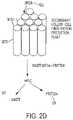
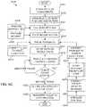
- the method of the present teachings for growing tissuecan include, but is not limited to including, producing a protein associated with the tissue, selecting cells associated with the tissue, expanding the cells, creating at least one tissue bio-ink including the expanded cells, printing the at least one tissue bio-ink in at least one tissue growth medium mixture, growing the tissue from the printed at least one tissue bio-ink, and maintaining viability of the tissue.
- the methodcan optionally include maintaining the tissue, and packaging the tissue for transport.
- Producing the proteincan include forming a recombinant protein precursor based on viral vectors associated with the tissue and cell lines associated with the tissue, forming disassociated protein precursor cells based on subjecting the recombinant protein precursor to at least one disassociation reagent and stress, creating at least one protein bio-ink based on the disassociated protein precursor cells and a sterile gel, creating at least one printable protein bio-ink based on the at least one protein bio-ink and at least one protein support material, printing the at least one printable protein bio-ink in at least one protein growth medium mixture, and growing the at least one printable protein bio-ink into the protein.
- the stresscan include mechanical stress and fluid stress.
- the at least one protein growth mediumcan include the sterile gel, a sterile basal medium, and a recombinant protein. Expanding the cells can include forming disassociated tissue precursor cells based on subjecting the selected cells to at least one disassociation reagent and stress, creating a growth medium associated with growing the disassociated tissue precursor cells, forming a tissue precursor recombinant protein mixture based on the protein associated with the tissue and indicators and support materials associated with the disassociated tissue precursor cells, forming a cell/medium mixture of the disassociated tissue precursor cells, the growth medium, and the tissue precursor recombinant protein mixture, and growing the expanded cells in a bioreactor loaded with the cell/medium mixture.
- At least one tissue bio-inkcan include the protein, tissue growth indicators, tissue growth factors, tissue support materials, and tissue gel.
- At least one tissue growth medium mixturecan include the protein, tissue gel, and basal medium.
- the system of the present teachings for growing tissuecan include a protein production process producing a protein associated with the tissue, a cell selection process selecting cells associated with the tissue, a cell expansion process expanding the cells, and a build process creating bio-ink based on the expanded cells and the protein, the build process printing the bio-ink in a growth medium mixture, the bio-ink growing into the tissue.
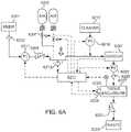
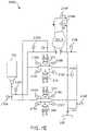
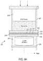
- the organ life support system to maintain and reproduce tissue and/or cellscan include, but is not limited to including, at least one incoming chamber configured to receive an incoming fluid, at least one corresponding effluent chamber configured to allow a fluid outflow from the system, the at least one corresponding effluent chamber further maintained at a pressure different from the at least one incoming chamber, at least one filtration zone, disposed between each of the at least one incoming chambers and the at least one corresponding effluent chamber, and a gel layer to contain tissue and/or cells.
- the method of the present teachings for automatically growing tissuecan include, but is not limited to including, selecting cells associated with the tissue, expanding the cells, creating at least one tissue bio-ink including the expanded cells, printing the at least one tissue bio-ink in at least one tissue growth medium mixture, growing the tissue from the printed at least one tissue bio-ink in the at least one tissue growth medium mixture, and maintaining viability of the tissue.
- the methodcan optionally include producing a protein associated with the tissue.
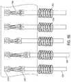
- the method of the present teachings for regrowing at least one axon of a nervous system and for restoring lost connections in the nervous systemcan include, but is not limited to including, providing, in a tissue enclosure, mechanical loading for axonal stretch growth of the at least one axon in at least one tissue-engineered nerve graft.
- the step of providing mechanical loadingcan include, but is not limited to including, attaching at least one integrative neuron, including the at least one axon, of the at least one tissue-engineered nerve graft to at least one sled within the bioreactor system.
- the at least one integrative neuroncan include a first end and a second end.
- the first endcan attach with a first set of the at least one sled, and the second end can attach with a second set of the at least one sled.
- the step of providing mechanical loadingcan include drawing apart the attached first set and the attached second set with a pre-selected force, and maintaining, by a plurality of load cells attached to at least one of the first set and the second set, the pre-selected force within a pre-selected limit.
- the plurality of load cellscan communicate with electromagnetically driven shafts that can engage with at least one of the first set and the second set.
- the pre-selected forcecan be maintained electromagnetically.
- the method for regrowing an axoncan include adjusting current signals sent to the electromechanically driven shafts when the at least one tissue-engineered nerve graft reaches maturity.
- the methodcan optionally include detecting indicators of potential damage during stretching based on information collected by sensors operably coupled with the tissue enclosure.
- the sensorscan optionally include at least one optical sensor and a microelectrode.
- the methodcan optionally include stimulating the at least one integrative neuron, and augmenting a rate of growth and minimizing breakage of the at least one axon based on an amount of nutrients provided in the tissue enclosure, growth factors and supplements provided, and an amount of waste products evacuated from the tissue enclosure.
- the bioreactor system of the present teachings for axonal stretch growth of tissuescan include, but is not limited to including, a plurality of sleds.
- Each of the plurality of sledscan be operably coupled with a movable shaft.
- a first set of the plurality of sledscan be engaged with a first end of a bundle of neurons, and a second set of the plurality of sleds can be engaged with a second end of the plurality of sleds.
- the systemcan include a plurality of load cells attached to the plurality of sleds, at least one sensor sensing movement of at least one of the plurality of sleds, and a bundle of neurons engaged on one end with a first set of the plurality of sleds.
- the bundle of neuronscan be engaged on a second end with a second set of the plurality of sleds.
- the systemcan include a controller monitoring the at least one sensor.
- the controllercan control the at least one sensor, the controller can control at least one environmental parameter in the bioreactor system, and the controller can command a pre-selected force to be applied to the bundle of neurons.
- the controllercan monitor the pre-selected force, and maintain the pre-selected force within a pre-selected limit.
- the movable shaftcan optionally be electromagnetically driven. The movement of the movable shaft can optionally be controlled by varying a current to the electromagnet.
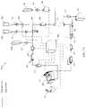
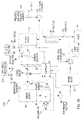
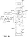
- the organ life support system for maintaining tissue of the present teachingscan include, but is not limited to including, at least one incoming chamber receiving an incoming fluid, and at least one effluent chamber allowing a fluid outflow from the system.
- the at least one effluent chambercan be maintained at a pressure different from the at least one incoming chamber.
- the organ life support systemcan include at least one filtration zone disposed between each of the at least one incoming chambers and the at least one effluent chambers, and a medium/tissue chamber housing the tissue and growth media.
- the medium/tissue chambercan receive the incoming fluid from the at least one incoming chamber through the at least one filtration zone, and the medium/tissue chamber can enable fluid flow to at least one effluent chamber through the at least one filtration zone.
- the pressure within at least one effluent chamberis optionally lower than the pressure within the at least one incoming chamber.
- the difference in pressurescan optionally be maintained by at least one pump.
- the at least one incoming chamber and the medium/tissue chambercan optionally be separated by one of the at least one filtration zones, and the medium/tissue chamber and the at least one effluent chamber can optionally be separated by one of the at least one filtration zones.
- the systemcan optionally include observation windows and sensors disposed within the at least one incoming chamber and the at least one effluent chamber.
- the at least one filtration zonecan optionally include a membrane filter.
- the at least one pumpcan optionally include a fluid pressure pump and/or a fluid vacuum pump.
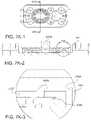
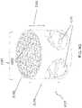
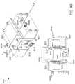
- the tissue enclosure of the present teachings enabling creation, maintenance, and monitoring of tissuecan include, but is not limited to including, a core including a cavity.
- the corecan include at least one monitoring area and at least one opening into the cavity.
- One of the at least one openingscan receive the tissue, and the core can accommodate at least one material ingress and at least one material egress.
- the tissue enclosurecan include at least one filter assembly operably coupled with the core. The tissue can be confined within the cavity by the at least one filter assembly, the life of the tissue can be maintained at least by fluid flowing through the cavity between the at least one material ingress and the at least one material egress, and the tissue can be monitored through the at least one monitoring area.
- the tissue enclosurecan optionally include at least one plenum operably coupled with the at least one filter assembly.
- the at least one plenumcan enable the application of pressure to the fluid and to the tissue.
- the tissue enclosurecan optionally include at least one heater that can maintain the temperature of the tissue, and at least one medium surrounding the tissue.
- the at least one mediumcan optionally include a gel.
- a multi-dimensional printercan optionally print the tissue into the cavity.
- the at least one filter assemblycan optionally include at least one filter, at least one filter support operably coupled with the at least one filter and at least one filter frame operably coupling the at least one filter and the at least one filter support with the at least one plenum.
- the tissue enclosurecan optionally include a tissue enclosure top removably enclosing the tissue within the core.
- the at least one monitoring areacan optionally include a transparent window.
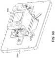
- the tissue enclosure of the present teachings enabling creation, maintenance, and monitoring of tissuecan include, but is not limited to including, a core including a cavity.
- the corecan include at least one monitoring area and at least one opening into the cavity.
- the tissue enclosurecan include at least one filter assembly operably coupled with the core.
- the tissue enclosurecan include at least one plenum swapably coupled with the at least one filter assembly during the maintenance of the tissue.
- the at least one plenumcan enable maintenance of the tissue by enabling the application of pressure to the material and the tissue.
- the tissuecan be printed into the cavity through the at least one opening.
- the tissuecan be maintained within the cavity by the at least one filter assembly.
- the tissuecan be monitored through the at least one monitoring area.
- the corecan optionally accommodate at least one material ingress and at least one material egress.
- the tissue enclosurecan optionally include at least one medium surrounding the tissue.
- the at least one mediumcan optionally include a gel.
- a multi-dimensional printercan optionally print the tissue into the cavity.
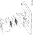
- the at least one filter assemblycan optionally include at least one filter, at least one filter support operably coupled with the at least one filter, and at least one filter frame operably coupling the at least one filter and the at least one filter support with the at least one plenum or the at least one block-off plate.
- the tissue enclosurecan optionally include at least one mounting feature operably coupled with the core, and a tissue enclosure mounting plate.
- the mounting platecan optionally include receiving features enabling kinematic mounting of the core at the at least one mounting feature.
- the at least one monitoring areacan optionally include a transparent window.
- the systemcan optionally include at least one block-off plate swapably coupled with the at least one filter during the creation of the tissue.
- the at least one block-off platecan be mounted on a side of the cavity opposing the at least one opening.
- the system of the present teachings for maintaining viability of tissuecan include, but is not limited to including, a tissue enclosure loaded with a print medium, and a pressure pump pumping at least one fluid through at least one fluid inlet in the print medium.
- the fluidcan provide nutrition to the tissue, and the tissue can create effluent based on the fluid.
- the systemcan include a vacuum pump evacuating the effluent though at least one fluid outlet in the tissue enclosure.
- the systemcan optionally include at least one window in the tissue enclosure enabling monitoring the tissue and the print medium.
- the tissue enclosure of the present teachings enabling creation and maintenance of tissuecan include, but is not limited to including, an incoming chamber containing media and tissue.
- the incoming chambercan admit a first material, and can emit a second material in response to a differential pressure within the tissue enclosure.
- the tissue enclosurecan include a filtration zone operably coupled with the incoming chamber.
- the filtration zonecan subject the first material, the second material, the media, and the tissue to at least one filter having a pore size based at least on the first material, the second material, the media, and the tissue.
- the filtration zonecan emit filtered contents based at least on the first material, the second material, the media, the tissue, and the pore size.
- the tissue enclosurecan include an effluent chamber operably coupled with the filtration zone.
- the effluent chambercan admit the filtered contents, and can manage the filtered contents.
- the differential pressurecan optionally result from atmospheric pressure being applied perpendicularly to the media and the tissue, and a vacuum pump being applied to the effluent chamber.
- the mediacan optionally include a gel.
- the tissuecan optionally include live human tissue.
- the first materialcan optionally include nutrition for the tissue.
- the second materialcan optionally include waste generated by the tissue.
- the filtered contentscan optionally result from recycling the filtered contents to the incoming chamber.
- Managing the filtered contentscan optionally include discarding the filtered contents.
- Managing the filtered contentscan optionally include monitoring the filtered contents.
- the filtration zonecan optionally include at least one filter sandwiched between at least one supporting mesh and at least one sealing frame.
- the tissue enclosure of the present teachings enabling creation and maintenance of tissuecan include, but is not limited to including, an incoming chamber including media and tissue.
- the incoming chambercan admit a first material, and can emit a second material in response to a differential pressure within the tissue enclosure.
- the tissue enclosurecan include a filtration zone operably coupled with the incoming chamber.
- the filtration zonecan subject the first material, the second material, the media, and the tissue to at least one filter having a pore size based at least on the first material, the second material, the media, and the tissue.
- the filtration zonecan emit filtered contents based at least on the first material, the second material, the media, the tissue and the pore size.
- the tissue enclosurecan include an effluent chamber operably coupled with the filtration zone.
- the effluent chambercan admit and manage the filtered contents.
- the tissue enclosurecan include at least one fluid outlet that can enable departure of fluid from the effluent chamber, and at least one vacuum outlet enabling a vacuum to be applied to the effluent chamber.
- the vacuumcan form, along with atmospheric pressure perpendicularly forcing contents of the incoming chamber, the pressure differential between the effluent chamber and the incoming chamber.
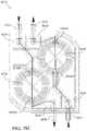
- the tissue enclosurecan optionally include a support structure including a plurality of tunnels disposed in a first orientation, and a plurality of ribs disposed in a second orientation.
- the support structurecan optionally operably couple with the filtration zone, and can optionally funnel the filtered contents from the filtration zone to the effluent chamber.
- a tissue enclosure of the present teachings enabling creation and maintenance of tissuecan include, but is not limited to including, an incoming chamber containing incoming chamber contents.
- the contentscan include the tissue, media, and a first material.
- the incoming chambercan emit a second material in response to a differential pressure within the tissue enclosure, and the incoming chamber can include a pressure inlet enabling pressure to be applied to the incoming chamber contents.
- the tissue enclosurecan include a filtration zone operably coupled with the incoming chamber. The filtration zone can subject the first material, the second material, the media and the tissue to at least one filter having a pore size based on the first material, the second material, the media and the tissue.
- the filtration zonecan emit filtered contents based on the first material, the second material, the media, the tissue and the pore size.
- the tissue enclosurecan include an effluent chamber operably coupled with the filtration zone.
- the effluent chambercan admit and manage the filtered contents.
- the tissue enclosurecan include at least one fluid outlet enabling departure of fluid from the effluent chamber, and at least one vacuum outlet enabling a vacuum to be applied to the effluent chamber.
- the vacuumcan form, along with atmospheric pressure perpendicularly forcing contents of the incoming chamber, the pressure differential between the effluent chamber and the incoming chamber.
- the tissue enclosurecan include at least one waste outlet enabling emission of waste from the effluent chamber.
- the tissue enclosurecan optionally include a support structure including a tunnel disposed in a first orientation, and a plurality of ribs disposed in a second orientation.
- the support structurecan operably couple with the filtration zone, and can include a plurality of tunnel structures feeding the filtered contents from the effluent chamber into the tunnel.
- the support structurecan funnel the filtered contents from the filtration zone through the tunnel to the waste outlet.
- the tissue enclosure of the present teachings enabling creation, maintenance, and monitoring of tissuecan include, but is not limited to including, an incoming chamber admitting a first material.
- the incoming chambercan emit the first material in response to a differential pressure within the tissue enclosure.
- the tissue enclosurecan include a core including a cavity.
- the corecan include, but is not limited to including, at least one monitoring area and at least one opening into the cavity.
- the corecan accommodate at least one material ingress and at least one material egress, and can include the tissue, media, and metabolism products from the tissue.
- the tissue enclosurecan include at least one first filtration zone operably positioned between the incoming chamber and the core.
- the filtration zonecan subject the first material to at least one filter having a first pore size based at least on the first material, and can emit first filtered contents to the core based at least on the first material and the first pore size.
- the tissue enclosurecan include at least one second filtration zone operably coupled with the core. The at least one second filtration zone can subject the first filtered material, the media, the tissue, and the metabolism products to at least one filter having a second pore size based at least on the first filtered material, the media, the tissue, and the metabolism products.
- the filtration zonecan emit second filtered contents based at least on the first filtered material, the media, the tissue, the metabolism products, and the second pore size.
- the tissue enclosurecan include an effluent chamber that can admit the second filtered contents, and can manage the filtered contents.
- the tissuecan enter the cavity through the at least one opening, the tissue can be confined within the cavity by the at least one first filtration zone and the at least one second filtration zone, the life of the tissue can be maintained by the first material entering the cavity through the at least one material ingress and by the metabolism products exiting the cavity through the at least one material egress, and the tissue can be monitored through the at least one monitoring area.
- the at least one openingcan optionally enable printing of the tissue.
- the at least one monitoring areacan optionally include a transparent window that can be disposed opposite the at least one opening.
- the tissue enclosurecan optionally include at least one mount button accommodating kinematic mounting of the tissue enclosure upon a tissue enclosure holder having corresponding mount wells.
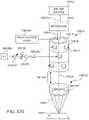
- the system of the present teachings for automatically growing tissuecan include, but is not limited to including, a cell expansion subsystem that can create at least one type of cell.
- the at least one type of cellcan be based on the tissue.
- the systemcan include an ink mixing subsystem that can combine the at least one type of cell with components to create a bio-ink.
- the systemcan include a life support enclosure that can include means for feeding the tissue, means for removing waste from the tissue, and means for transporting the tissue.
- the systemcan include a build subsystem that can print the bio-ink in the life support enclosure.
- the printed bio-inkcan form the tissue, and the life support enclosure can house the tissue.
- the system componentscan optionally include protein and gel.
- the systemcan optionally include a protein production subsystem that can create the protein.
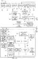
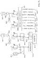
- the system of the present teachings for automatically growing tissuecan include, but is not limited to including, a controller providing commands to the system, and a growth medium subsystem responding to the commands.
- the growth medium subsystemcan produce growth medium.
- the systemcan include a build subsystem that can respond to the commands.
- the build subsystemcan receive, at least, cells associated with the tissue and the growth medium, and the build subsystem can create the tissue based at least on the cells and the growth medium.
- the systemcan include a growth subsystem that can respond to the commands.
- the growth subsystemcan grow the created tissue into a pre-selected mature tissue.
- the systemcan include a maintenance subsystem that can respond to the commands.
- the maintenance subsystemcan maintain the viability of the pre-selected mature tissue.
- the systemcan include a tissue pack subsystem that can transport the viable mature tissue to a patient.
- the growth mediumcan optionally include indicators, support materials, gel, protein, and basal medium.
- the build subsystemcan optionally create the protein.
- the proteincan optionally include commercially-available protein.
- the build subsystemcan optionally include a bio-ink subsystem responding to the commands.
- the bio-ink subsystemcan receive cells, the indicators, growth medium, and the support materials, and can create a bio-ink.
- the build subsystemcan optionally include a printer subsystem that can respond to the commands.
- the printer subsystemcan receive the bio-ink, and can print the bio-ink.
- the build subsystemcan optionally include a bioreactor subsystem that can respond to the commands.
- the bioreactor subsystemcan receive the printed bio-ink, and the growth medium from the growth medium subsystem, and can provide the tissue to the maintenance subsystem.
- the maintenance subsystemcan include a solid tissue subsystem that can respond to the commands.
- the solid tissue subsystemcan receive the tissue from the build subsystem, and can transmit viability and nutrition status of the tissue.
- the maintenance subsystemcan include a fluid bioreactor subsystem that can respond to the commands.
- the fluid bioreactor subsystemcan receive the viable tissue from the solid tissue subsystem, and can incubate the viable tissue received from the solid tissue subsystem, along with at least in the growth medium received from the growth medium subsystem, supplements, diluent, and basal media.
- the fluid bioreactor subsystemcan provide viable incubated tissue.
- the maintenance subsystemcan include a packaged tissue subsystem that can enable the transport of the viable incubated tissue.
- the growth medium subsystemcan include a disassociated cell subsystem that can respond to the commands.
- the disassociated cell subsystemcan create disassociated cells based at least on incoming cells, viral vectors, and commercial protein, and can provide the disassociated cells to the build subsystem.
- the growth medium subsystemcan include a print medium subsystem that can respond to the commands.
- the print medium subsystemcan create the growth medium based at least on the indicators, support materials, carbomer, the basal media, and the protein.
- the growth medium subsystemcan include a protein subsystem that can respond to the commands.
- the protein subsystemcan receive the protein from the build subsystem and can supply the protein to the print medium subsystem.
- the controllercan include a feedback controller controlling the flow and composition of fluid to and through the tissue.
- the feedback controllercan communicate through the commands formatted according to a communications protocol.
- the feedback controllercan receive sensed information from at least one sensor, and can base the commands at least on the sensed information.
- the systemcan optionally include a dialysis/recirculation subsystem that can cleanse the fluid after the fluid has passed through the tissue, and can return the fluid to the tissue.
- the system of the present teachings for incubating an organcan include, but is not limited to including, an organ scaffold that can host the organ, and a tube that can operably couple with the organ scaffold.
- the tubecan provide a conduit between a fluid source and the organ scaffold.
- the systemcan include a chamber that can house the organ scaffold.
- the chambercan include at least one inlet and at least one outlet.
- the at least one inletcan receive fluids, and the fluids can maintain viability of the organ.
- the at least one outletcan evacuate wastes from metabolism of the organ.
- the systemcan optionally include at least one pump that can operably couple with the at least one inlet.
- the at least one pumpcan pump fluids into the chamber through the at least one inlet.
- the at least one pumpcan enable pressure to be applied to the fluids and the wastes, and can enable the movement of the fluids and the wastes through the chamber.
- the organ scaffoldcan optionally include a fluid cavity that can enable the receiving of fluids into and the emitting of fluids from the interior of the organ scaffold.
- the fluid cavitycan include an inner surface and an outer surface. The inner surface can provide a boundary for the received fluids.
- the organ scaffoldcan include a compliant wrapper that can operably couple with the outer surface.
- the compliant wrappercan enable inflation and deflation of the fluid cavity.
- the organ scaffoldcan include at least one layer of fiber that can be disposed upon the compliant wrapper.
- the at least one layer of fibercan be disposed in the shape of the organ.
- the organ scaffoldcan include a plurality of cells that can be disposed upon the at least one layer of fiber. The plurality of cells can be associated with the biology of the organ.
- the system of the present teachings for monitoring activity in tissuecan include, but is not limited to including, at least one resonator including a thermally sensitive material.
- the thermally sensitive materialcan have absorption properties, and the absorption properties can be adjustable based at least on heat attained.
- the at least one resonatorcan include at least one inductive component and at least one capacitive component.
- the systemcan include at least one illuminator that can illuminate the resonator.
- the at least one illuminatorcan enable the at least one resonator to absorb energy and convert the energy into heat.
- the systemcan include at least one receiver monitoring the frequency of the illuminated at least one resonator as the tissue changes.
- the at least one illuminatorcan optionally periodically illuminate the at least one resonator.
- the at least one illuminatorcan optionally continuously illuminate the at least one resonator, reversing polarity periodically during the continuous illumination.
- the at least one inductive componentcan optionally store energy, the at least one inductive component can optionally discharge the stored energy when the polarity is reversed, and the discharged energy can optionally be stored in the at least one capacitive component.
- the periodic storing and discharging of energycan convert the energy into heat.
- the systemcan optionally include at least one diode that can convert the energy absorbed by the resonator into a control pulse or a DC voltage or both.
- a plurality of the at least one diodecan create various voltage gradients across the tissue, and the various voltage gradients can mimic bioelectrical potentials in the tissue.
- the method of the present teachings for monitoring activity of tissuecan include, but is not limited to including, printing the tissue within a tissue enclosure, and printing at least one sensing element within the tissue.
- the at least one sensing elementcan enable sensing of low energy signals produced by the tissue.
- the methodcan include printing at least one structure within the tissue enclosure.
- the at least one structurecan surround the tissue, and the at least one structure can isolate the signals generated by the tissue.
- the method of the present teachings for electrospinning biological materialcan include, but is not limited to including, energizing a needle with a pre-selected voltage, and pumping the biological material into the needle.
- the pumping and the energizingcan force the biological material into an energized droplet stream.
- the methodcan include transmitting an RF signal of a pre-selected phase angle across an array of antennas.
- the array of antennascan each be associated with at least one resonator.
- the antennas and resonatorscan have a pre-selected geometry, and the array of antennas can substantially surround the energized droplet stream.
- the methodcan include creating a voltage gradient by adjusting the phase angle of the RF signal.
- the voltage gradient and the pre-selected geometrycan create a torque on the energized droplet stream.
- the torquecan move the droplet stream to a pre-selected position on a surface.
- the pre-selected voltagecan optionally be greater than 10 kV.
- the methodcan optionally include pumping the biological material into a reservoir, and pumping the biological material from the needle into a nozzle.
- the nozzlecan direct the energized droplet stream, and the energized droplet stream can have a diameter of approximately 10 ⁇ m.
- the surfacecan optionally include a collector plate and/or tissue.
- FIG. 1is a schematic block diagram of the tissue engineering environment of the present teachings
- FIG. 1Ais a schematic block diagram of the tissue engineering system of the present teachings
- FIG. 1Bis a schematic block diagram of the build or grow subsystem of the present teachings
- FIG. 1Cis a schematic block diagram of the maintenance subsystem of the present teachings.
- FIG. 1Dis a schematic block diagram of the growth medium subsystem of the present teachings.
- FIG. 1Eis a schematic block diagram of the feedback controller of the present teachings.
- FIGS. 2A-2Care schematic block diagrams of an alternate configuration of the tissue engineering system of the present teachings.
- FIG. 2Dis a pictorial representation of another alternate configuration of the tissue engineering system of the present teachings.
- FIGS. 3A and 3Bare schematic block diagrams of the assay bioreactor of the present teachings.
- FIGS. 4A and 4Bare schematic block diagrams of the protein bioreactor of the present teachings.
- FIGS. 5A-5Eare schematic block diagrams of the lung bioreactor of the present teachings.
- FIG. 6Ais a schematic block diagram of an exemplary system for growing tissue of the present teachings.
- FIG. 6Bis a schematic block diagram of another exemplary system for growing tissue of the present teachings.
- FIGS. 6C-6Eare flowcharts of a method of the present teachings for growing tissue
- FIGS. 7A and 7Bare schematic block diagrams of second and third configurations of the tissue maturation system of the present teachings.
- FIGS. 7C-7Gare schematic block diagrams of exemplary configurations of the tissue maturation system of the present teachings.
- FIGS. 7H-7Kare schematic diagrams of the single unit mix cassette of the present teachings.
- FIGS. 7K-1, 7K-2, and 7K-3are cross sections of the mixing cassette as in FIGS. 7H-7K ;
- FIG. 7Lis a schematic block diagram of a tissue exerciser system of the present teachings.
- FIG. 7Mis a schematic diagram of the pumping cassette of the present teachings.
- FIG. 8Ais a schematic block diagram of the nerve growth system of the present teachings.
- FIG. 8Bis a pictorial representation of the nerve growth system of the present teachings.
- FIG. 9Ais a pictorial representation of the first configuration of the bioreactor of the present teachings.
- FIG. 9Bis a perspective schematic view of the first configuration of the bioreactor of the present teachings.
- FIG. 9Cis a schematic perspective exploded view of the first configuration of the bioreactor of the present teachings.
- FIG. 9Dis a pictorial representation of the second configuration of the bioreactor of the present teachings.
- FIG. 9Eis a perspective schematic view of the second configuration of the bioreactor of the present teachings.
- FIG. 9Fis a schematic cross section view of the second configuration of the bioreactor of the present teachings.
- FIG. 9Gis a perspective schematic view of the support structure of the second configuration of the bioreactor of the present teachings.
- FIG. 9His a pictorial representation of the third configuration of the bioreactor of the present teachings.
- FIG. 9Iis a perspective schematic view of the third configuration of the bioreactor of the present teachings.
- FIG. 9Jis a schematic cross section view of the third configuration of the bioreactor of the present teachings.
- FIG. 9Kis a schematic perspective exploded view of the third configuration of the bioreactor of the present teachings.
- FIG. 9Lis a perspective schematic view of the support structure of the third configuration of the bioreactor of the present teachings.
- FIG. 9Mis a pictorial representation of the fourth configuration of the bioreactor of the present teachings.
- FIG. 9Nis a perspective schematic view of the fourth configuration of the bioreactor of the present teachings.
- FIGS. 9O, 9P, and 9Qare schematic perspective exploded views of the fourth configuration of the bioreactor of the present teachings.
- FIG. 9Ris an exploded schematic perspective of the fifth configuration of the filter of tissue enclosure of the present teachings.
- FIG. 9Sis a cross section of the interior of the tissue enclosure of FIG. 9R ;
- FIG. 9Tis an schematic perspective of the sixth configuration of the tissue enclosure of the present teachings.
- FIG. 9Uis a schematic perspective of the tissue enclosure of FIG. 9T mounted on a printing mounting plate
- FIG. 9Vis the opposite side of the tissue enclosure and mounting plate of FIG. 9U ;
- FIG. 9Wis a schematic block diagram of the sixth configuration tissue enclosure in printing mode
- FIG. 9Xis a schematic perspective exploded view of the sixth configuration tissue enclosure in printing mode
- FIG. 9Yis a schematic perspective of the sixth configuration of the tissue enclosure of the present teachings in life support mode
- FIG. 9Zis a schematic perspective of the core of the sixth configuration of the tissue enclosure of the present teachings.
- FIG. 9AAis a schematic perspective diagram of the exploded bladder bioreactor of FIG. 9AA-1 ;
- FIG. 9AA-1is a schematic exploded perspective diagram of a bladder bioreactor of the present teachings.
- FIG. 9BBis a schematic block diagram of a system employing the bladder bioreactor of FIG. 9AA ;
- FIG. 10is a pictorial representation of a system of the present teachings for monitoring tissue activity
- FIGS. 11A-11Care pictorial representations of the optics-based tissue monitoring system of the present teachings.
- FIG. 12Ais a pictorial representation of the first configuration of the precise printing apparatus of the present teachings.
- FIG. 12Bis a pictorial representation of the second configuration of the precise printing apparatus of the present teachings.
- FIG. 12Cis a pictorial representation of the third configuration of the precise printing apparatus of the present teachings.
- FIG. 12Dis a pictorial representation of the signal treatment of the configurations of FIGS. 12A, 12B, and 12C of the present teachings.
- references to fastenerscan include any type of fastening mechanism including, but not limited to, glue, bolts, screws, nails, and hook-and-eye devices.
- tissue engineering environment 500 Acan expand cells, create biological and support mixtures for printing and growing the cells into tissue, print the mixtures as tissue into a life support enclosure, maintain the viability of the tissue in the life support enclosure, and transport the mature, viable tissue in the life support enclosure.
- Tissue engineering environment 500 Acan include partial and/or complete automation in which each phase of tissue creation and phase transitions can be directed by a controller that can receive feedback on the status of the process and the viability of the tissue.
- the life support enclosurecan include features that can enable tissue creation, maintenance, and transport without moving the tissue from one enclosure to another.
- Cell expansion 955can create the cells necessary to create the desired tissue.
- Cell expansion 955can rely on, for example, plate expansion 951 or expansion 953 in a life support system (LSS) of the present teachings, to create cells 501 .
- Ink mixing 957can include creating bio-ink 504 based on one, or some, or all of cells 501 , protein 535 , and gel 509 .
- Protein 535can be grown within tissue engineering environment 500 A or can be commercially acquired, for example.
- Build 513 Acan include printing the tissue using printer 587 from bio-ink 504 into LSS 700 . After the tissue is printed into LSS 700 , maintenance subsystem 515 can maintain the viability of the tissue in the LSS 700 . Over time, as the tissue ages, waste products can be produced, and the tissue can require nutrition.
- LSS 700can include fluid bioreactor 963 that can enable fluid transfer across the tissue to provide nutrition and remove wastes.
- transport 965can move LSS 700 , including the tissue, to a final destination, such as, for example, a transplant recipient.
- growth medium subsystem 517Some of the components that can be received by growth medium subsystem 517 can be chosen to grow a particular kind of cell and/or organized group of cells—tissue 529 —and can create growth medium 533 .
- Growth medium 533can be characterized optically.
- Tissue 529can grow in and be maintained in a sterile carbomer granular gel preparation that can include photonic markers.
- Build subsystem 513 A and grow subsystem 513 Bcan receive a combination of the components through a second of fluid pathways 2029 .
- the combination of componentscan depend on a desired resultant tissue 529 , including, for example, but not limited to, output from the growth medium subsystem 517 .
- Maintenance subsystem 515can nurture expanded cells, protein producing cells 535 , and tissue 529 received through a first of tissue pathways 2029 A until they are needed by other parts of system 500 or as transplants, for example.
- Controller 519can include subcontrollers for various parts of system 500 that can manage the interactions among the components of system 500 through signals sent over data/communications pathways 2029 .
- build subsystem 513 A and grow subsystem 513 Bcan create an environment for growth of, for example, but not limited to, tissue 529 and protein producing cells 535 .
- Build subsystem 513 A and grow subsystem 513 Bcan include, but are not limited to including, bio-ink subsystem 514 , and bioreactor subsystem 700 .
- Build subsystem 513 Acan include printer subsystem 270 which can print bio-ink 504 into bioreactor subsystem 700 .
- Cells 501 , indicators 505 , support materials 507 , and growth media 533can be supplied to bio-ink subsystem 514 .
- Bio-ink subsystem 514can create bio-ink 504 that can be used to print desired biological material to bioreactor subsystem 700 .
- Bio-inks 504can be mixed together according to a recipe that can enable growth and maintenance of tissue 529 and can reduce the number of print heads necessary.
- Bio-inks 504can include, but are not limited to including, cells, carbomer, markers, and dots, for example.
- Bioreactor subsystem 700can incubate printed bio-ink 504 in growth media 533 that is chosen based on bio-ink 504 and desired biological structures such as, but not limited to, tissue 529 and protein producing cells 535 .
- Controller 519can direct fluid and tissue flow through data/communications pathways among subsystems.
- Electronic communications 2047 Xcan include wired and wireless means.
- maintenance subsystem 515can ensure that biological material created by build subsystem 513 A can remain viable until it is used in, for example, but not limited to, a transplant.
- Maintenance subsystem 515can include, but is not limited to including, solid tissue subsystem 525 , fluid bioreactor subsystem 800 , and packaged tissue subsystem 527 .
- An exemplary fluid bioreactor subsystem 800is described in U.S. patent application Ser. No. 15/288,900, entitled FLUID PUMPING AND BIOREACTOR SYSTEM, ('900).
- Build subsystem 513 Acan provide biological material, for example, but not limited to, tissue 529 to solid tissue subsystem 525 that can transfer viable tissue 529 to fluid bioreactor subsystem 800 .
- Fluid bioreactor subsystem 800can maintain viability of biological material such as, for example, but not limited to, tissue 529 and protein producing cells 535 until the biological material is needed by supplying, for example, but not limited to, supplements 321 , diluent 395 , basal media 349 , air products 359 , solvents 393 , cleaner 391 , and growth media 533 to the biological material in quantities that can maintain viability of the biological material.
- Controller 519can adjust the amounts and rates of delivery of substances to the biological material according to a pre-defined recipe, and can control draining/recycling of waste material.
- packaged tissue subsystem 527can store tissue 529 for portability in tissue package 529 A.
- Tissue package 529 Acan include, but is not limited to include, a material coated with a hydrophobic material. Transferring protein producing cells 535 and tissue 529 between physical enclosures, if necessary, can include insuring sterility in the environment surrounding the biological material being transferred.
- growth medium subsystem 517can enable creation of specific growth media for a given biological material outcome.
- Growth medium subsystem 517can include, but is not limited to including, disassociated cell subsystem 531 , print medium subsystem 533 , and protein subsystem 535 .
- Growth media 533can be developed based upon the desired biological material.
- Growth media 533can include, for example, but not limited to, basal media 557 , carbomer powder 553 , indicators 505 , support materials 507 , and proteins 535 .
- Disassociated cell subsystem 531can create disassociated cells 501 A from, for example, but not limited to, supplied cells 501 , commercial protein producing cells 535 A, and viral vectors 567 .
- Supplied cells 501can include, but are not limited to including, patient biopsy cells 541 ( FIG. 2A ) from which can be created patient stem cells 543 ( FIG. 2A ) which can then become differentiated stem cells 545 ( FIG. 2A ) or immortalized cell lines 547 ( FIG. 2A ) isolated patient cell lines 549 ( FIG. 2A ), for example.
- Commercially-available or otherwise procured viral vectors 567 and immortalized cell lines 571can be combined by transduction to produce protein producing cell lines 569 .
- Growth media 533can be supplied to build subsystem 513 A to promote growth of the desired biological material, and to maintenance subsystem 515 to maintain tissue 529 that results from the growth of the desired biological material.
- Disassociated cell subsystem 531can isolate cells according to the desired biological material outcome and the source of the cells. Disassociated cell subsystem 531 can disassociate the cells based on the source of the cells, for example, cells resulting from a biopsy can require disassociation. Cells can be disassociated using, for example, a reagent such as trypsin to wash the cells and then isolate the cells using standard techniques A flow cytometer can be used to sort disassociated cells, and the sorted cells can be suspended in a solution and mixed with, for example, gel, media, and proteins.
- controller 519can coordinate the activities of build subsystem 513 A, maintenance subsystem 515 , and growth media subsystem 517 so that together they can achieve the given biological material outcome.
- Controller 519can include feedback controller 2047 that can control the flow of cells and fluid to and through biological material such as, for example, but not limited to, protein producing cells 535 , and tissue 529 .
- the cells and fluidflow through fluid pathways 2029 ( FIG. 1A ) and tissue pathways 2029 A ( FIG. 1A ) to/from build subsystem 513 A, growth media subsystem 517 , and maintenance subsystem 515 .
- Feedback controller 2047can control the path and amount of fluid/tissue through system 500 .
- Feedback controller 2047can communicate with other parts of system 500 through, for example, but not limited to, an CANbus interface using a protocol such as, for example, but not limited to, the CAN protocol (referred to herein as CANbus interface), and can receive information about other parts of system 500 from, for example, sensors 2027 .
- Sensors 2027can include, but are not limited to including, temperature, pressure, conductivity, leak detection, air-in-line, and flow rate.
- Feedback controller 2047can, for example, calibrate pressure sensors through messages routed over the CANbus interface, update pressure readings, and display flow diagram valve pressures.
- Feedback controller 2047can execute step-by-step tissue creation according to, for example, but not limited to, feedback process 2047 A, and in addition, feedback controller 2047 can accept override commands from, for example, but not limited to, graphical user interface (GUI) 2037 .
- GUIgraphical user interface
- feedback controller 2047can communicate with, for example, but not limited to, sensors 2027 , GUI 2037 , and feedback process 2047 A either directly or through electronic communications 2047 X.
- Some configurationscan include 2-way communications between feedback process 2047 A and feedback controller 2047 , as well as 2-way communications between GUI 2037 and feedback controller 2047 .
- feedback controller 2047can read and modify feedback process 2047 A either statically or dynamically.
- feedback controller 2047can receive information from GUI 2037 , such as, for example, recipe override information, and can supply information to GUI 2037 as the system proceeds through biological material creation processes.
- Some configurationscan include 2-way communications between GUI 2037 and feedback process 2047 A.
- GUI 2037can read and modify feedback process 2047 A when, for example, a step, precondition, pressure, port, flow rate, mode, and/or duration is entered into GUI 2037 that differs from feedback process 2047 A.
- Some configurationscan include 1-way communications between feedback process 2047 A and feedback controller 2047 in which feedback controller 2047 can read, but not modify, feedback process 2047 A.
- Some configurationscan include 2-way communications among all of feedback process 2047 A, GUI 2037 , and feedback controller 2047 .
- feedback controller 2047can direct fluid flow based on both feedback process 2047 A and GUI 2037 by receiving information from feedback process 2047 A and/or GUI 2037 , reconciling conflicting commands dynamically, opening/closing valves, and starting/stopping pumps based on the reconciled commands.
- feedback controller 2047can dynamically update GUI 2037 while receiving commands from GUI 2037 .
- feedback process 2047 Acan be isolated from changes attempted through GUI 2037 , and can be isolated from modifications attempted by feedback controller 2047 .
- feedback controller 2047can log data, for example pressure data. To maintain the size of log 3061 , feedback controller 2047 can trim excessive old first elements off log 3061 while adding new data to the end of log 3061 . Feedback controller 2047 can decide dynamically or statically which elements to trim. Feedback controller 2047 can also adjust the logging sample rate, for example, based on the amount of memory available. Errors, email information, valve status, pump configuration, pump status, control status, reservoir status, preconditions, recipe step status, priming status, GUI selections, logging status, solution status, override status, enclosure status, recipe load status, hardware status, and system state can be logged.
- Feedback controller 2047can recognize states 3051 / 3049 that can guide execution of feedback process 2047 A ( FIG. 31A ).
- Feedback controller 2047can connect to hardware using, for example, a process that can include, but is not limited to including, if the CANbus interface is disconnected, feedback controller 2047 can connect the CANbus interface, start control of the system, and read the hardware configuration before a search for devices is initiated.
- Feedback controller 2047can update hardware status by, for example, but not limited to, getting/showing the status of any of the pumps in the system.
- Feedback controller 2047can also reset hardware.
- Feedback controller 2047can initialize pause times and start time of feedback process 2047 A. The steps of feedback process 2047 A can each include a duration.
- starting and ending times of each stepcan be determined based on the start time of feedback process 2047 A.
- Each stepcan have preconditions that can be checked and fulfilled before the step of feedback process 2047 A is executed. If feedback process 2047 A is restarted, or if another feedback process 2047 A is loaded, feedback controller 2047 can perform housekeeping such as, for example, setting an appropriate active state 3051 . To pause and resume feedback process 2047 A, preconditions can be checked for next step 3049 . Automatic changes of state 3049 / 3051 and other processing of states 3049 / 3051 can be blocked while in a paused state.
- Feedback controller 2047can stop any of the devices in the system before proceeding to next step 3049 in feedback process 2047 A, as a part of feedback process 2047 A, as a part of an error condition, and as part of a manual override.
- Feedback controller 2047can update the progress of each step of feedback process 2047 A.
- Feedback controller 2047can receive information from sensors 2027 that can update feedback process 2047 A based on the current conditions sensed in system 500 ( FIG. 1A ). For example, if tissue 529 is found to need specific ingredients in growth medium 533 , the specific ingredients may be introduced into system 500 until sensors 2027 determine that tissue 529 needs other different attention.
- Feedback process 2047 Acan begin with an initial “recipe” that can be continually updated based on the information received from, for example, but not limited to, sensors 2027 and GUI 2037 .
- system 540is an alternate configuration of system 500 ( FIG. 1A ).
- System 540can produce and maintain protein producing cells 535 and tissue 529 .
- System 540can include cell expansion subsystem 550 , protein production subsystem 560 , and tissue creation subsystem 570 .
- Cell expansion subsystem 550can create cells that are specific for creating a certain type of tissue. There can be multiple configurations of cell expansion 550 each expanding a type of cell necessary for a specific tissue. Alternatively, there can be multiple types of cells resulting from one configuration of cell expansion subsystem 550 .
- Cell expansion subsystem 550can grow cells in a medium in three dimensions at high density.
- System 540can include processes that can combine specific growth factors and media, diffuse media, and enable cell expansion.
- System 540can include a process that can enable continued viability of cells before, during, and after cell expansion, and can enable removal of the gel by changing the ionic strength in system 540 .
- System 540can include photonic markers with the media.
- Cell expansion subsystem 550can monitor the characteristics of cells in real time.
- disassociated cells in suspension 573 and sterile carbomer granular gel preparation 575can combine to produce bio-ink 577 that can be printed, along with protein support materials 585 (along with, for example, but not limited to, indicators, air, and chemical attractants), by printer 587 into protein LSS 900 and incubated therein.
- Sterile carbomer granular gel preparation 575can combine with sterile basal media preparation 579 and recombinant proteins 581 to produce granular gel protein growth media 583 which can be supplied to protein LSS 900 to maintain viability of the protein growing therein.
- protein production subsystem 560can produce protein producing cells 535 necessary for a particular cell expansion and for particular tissue growth, as well as to stock and distribute for use external to system 540 .
- Protein production subsystem 560can enable a batch-like process of protein production and/or a continuous process of protein production by, for example, washing medium through a hollow fiber-shaped bioreactor 367 D. The walls of the hollow bioreactor and cells thereon can be continually replenished with growth media and be continuously monitored.
- Protein production system 560can include a series of tubes that can form a hollow fiber system formed by the protein producing cells.
- Protein production system 560can include mechanisms to detach cells from surfaces where they might have attached during growth, for example, but not limited to a centrifuge-like structure and specific enzymes, systems that can maintain characteristics of the cells such as, for example, but not limited to, the pH and the temperature.
- Visual analysis 311FIG. 2C
- An organ life support systemcan include a granular gel bioreactor that can include a suspension of recombinant protein expressing cells.
- a fluid bioreactorcan include plumbed, previously fabricated, recombinant protein expressing tissue construct. Selection of an OLSS or a fluid bioreactor can depend upon relative protein expression rates of suspended constructs versus tissue constructs for a given cell type and protein, and the application such as, for example, but not limited to, large organs, cancer screening, drug screening, small organs, cell expansion, and protein production. Physical construction of the bioreactor can depend upon the expected size of the contents during tissue growth.
- the bioreactorcan include durable, possibly metal, parts, and/or disposable parts. Large organs can possibly require a relatively large durable bioreactor, for example, a bioreactor that can hold 10 liters of fluid and can measure 8 inches on a side.
- Drug screenscan possibly require a relatively small disposable bioreactor, for example, a bioreactor that can hold 0.1 liter that can include a tube or ball of cells and can measure 10 ⁇ 10 cm, 0.1 cm thick.
- a vertically-oriented bioreactorcan accommodate large organs, for example, and a horizontally-oriented bioreactor can accommodate small tissues, for example. Because the OLSS and the fluid bioreactor may be one and the same, they may be referred to herein collectively as a bioreactor.
- components of system 540can be modular and can be specifically designed for an application.
- the bioreactorcan include a cavity that can accommodate a few milliliters to thousands of liters of fluid, depending upon the application.
- the orientation, shape, filter material, number of filters, mesh, air/fluid pressure, dialysis recirculation, reusability, and desired flow ratescan vary with the type and size of the bioreactor.
- Each bioreactorcan include, but is not limited to including, at least one inlet for fluid (liquid and/or gaseous), at least one chamber for holding the granular gel media and imbedded cells or the previously fabricated tissue construct with plumbing for fluid flow or cells on a scaffold.
- the bioreactorcan include at least one filter, for example, but not limited to, etched plastic or hydrogel, at least one support for holding the filter in place, at least one effluent chamber, and at least one outlet port.
- the number, size, construction, materials, and location of the filters in the bioreactorcan be based upon the application and the desired density of cells, and can be determined based on metabolite usage, visual sensors, and impedance measurement, for example.
- Smaller horizontal flow bioreactorscan include transparent components that can accommodate viewing of the interior of the bioreactor with, for example, at least one microscope.
- the bioreactorcan include sterilizable materials and/or disposable materials.
- a protein production process enabled by protein production subsystem 560can include selecting viral vectors 567 based on the desired protein. Multiple proteins can be produced simultaneously using cell lines that are physically separated until they are printed.
- the protein processcan include transducing immortalized cell lines 571 with viral vectors 567 to produce recombinant protein producing cell lines 569 , adding a disassociation reagent to produce disassociated cells in suspension 573 , and applying a stress to mix protein producing cells 569 with granular gel 575 to produce bio-ink 577 .
- the stresscan be, for example, but not limited to, mechanical or sheer stress.
- the protein processcan include mixing support material according to the desired protein and loading bio-ink 577 into printer 587 .
- the support materialcan include mixing granular gel 575 , basal media 579 , and recombinant proteins 581 to produce growth media 583 specific for protein growth, and neutralizing growth media 583 .
- the protein processcan include printing bio-inks 577 into protein OLSS 900 where growth media 583 have been placed. Bio-inks 577 can be printed into any shape.
- the protein processcan include providing a flow of, for example, nutrients through protein OLSS 900 , and testing the outgoing effluent to determine how much protein is being produced.
- the protein processcan include harvesting and purifying the protein, and maintaining the viability of the protein in solid tissue construct 593 in protein fluid bioreactor 591 .
- cell expansion subsystem 550can include a cell process for cell expansion.
- the cell processcan include adding a disassociation reagent to cell lines to form disassociated cells in suspension 555 .
- Cells from patient biopsy 541for example, can be sorted according to the desired tissue, or all the cells can be placed in cell growth media 559 that can be tailored to allow a specific type of cell to thrive.
- the cell processcan include mixing sterile power 553 with basal media 557 and neutralizing the mixture to provide gel for cell growth media 559 .
- the processcan include mixing indicators 563 , proteins for cell expansion 565 , the gel, and disassociated cells in suspension 555 to form cell growth media 559 .
- the processcan include placing or printing the mixture into cell OLSS 700 , growing the cells, and determining when to terminate the cell growth stage when a pre-selected number of cells has been reached.
- the processcan include isolating the grown cells from the growth media, for example, by crashing the media. Crashing the media can include adding enough salt to change the balance of ions and disrupt the polymer chains of the gel. Cells can be harvested from the crashed media and can be resuspended in another medium, for example, for transport.
- the processcan include removing some of the cells, thus allowing more space for cells to grow.
- tissue growth processthat can be associated with tissue creation subsystem 570 can include, but is not limited to including, mixing cells 595 , indicators 597 , and gel 575 to create tissue bio-inks 504 .
- the tissue growth processcan include selecting proteins based on the desired tissue, the stage of the cells, and the desired activity of the cells. Multiple proteins can be used to seed a single tissue growth OLSS 700 ; which protein is delivered at what time can be controlled. The mixture in tissue OLSS can be chemically optimized based on the desired tissue.
- the tissue growth processcan include creating tissue growth media 506 based on gel 575 , recombinant proteins for tissue growth 599 , and basal media 502 .
- Tissue grown media 506can be prepared in a batch, and can be maintained in a pre-selected temperature range, for example, 37° C. ⁇ 1° C. Recombinant proteins for tissue growth 599 can be added to the batch at a later time, for example, after neutralization.
- the tissue growth processcan include loading growth media 506 into tissue growth OLSS 700 before printing begins, and printing tissue bio-inks 504 with printer 587 , continually correcting the mixture based on information provided by sensors. Correction can be based on, for example, pH balance, oxygen level, and flow rate.
- the tissue growth processcan include determining when the tissue is complete and optionally moving solid tissue construct 512 to tissue fluid bioreactor 514 to ripen the tissue and maintain its viability through use of fluid growth media 516 A. If an organ is being grown, the tissue growth process is complete when automatically-determined tests indicate that the organ fulfills its function. Further, tissue that can be used to test treatment protocols can be grown, for example, tumors can be grown to test cancer treatment protocols.
- OLSS tissue generator system 700can provide an environment that can create and maintain biological materials in, for example, but not limited to, a carbomer-like material.
- various types of materialscan be pumped into system 700 , their status can be tested before entering OLSS 367 , and the status of the products exiting OLSS 367 can be tested.
- the progress of the biological material within OLSS 367can be monitored throughout the growth and maintenance cycles to correct any imbalances and to determine the status of the biological materials.
- System 700can determine by these various tests when the biological material has reached its progress goals.
- the biological materialcan grow in an environment that can include a carbomer-based product.
- a family member of carbomer-based productscan be chosen to include in the biological material environment based on variations in physical properties such as, for example, but not limited to, neutralized viscosities and pH ranges, that can provide characteristics needed for specific tissue outcomes.
- Sodium hydroxidecan be used to neutralize the gel, or a neutral carbomer product can be used.
- the carbomer-based productcan be combined with basal medium such as, for example, but not limited to, salts, amino acids, simple sugars, and buffers, and can be neutralized by sodium hydroxide to produce a gel.
- Basal mediumcan be required to maintain cell viability.
- An optimal ratio of basal medium to carbomercan allow the cells to remain in suspension in the gel.
- the biological materialcan be fed by pumping and/or vacuuming growth medium 533 ( FIG. 1A ) through gel, and by, for example, diffusion.
- controller 329can direct an agitation device (not shown) to agitate bioreactor 367 to enhance diffusion.
- Other methods of enhancing diffusioncan be used.
- the order of adding materialscan be adjusted to enhance diffusion/dispersion, and can be adjusted to avoid undesirable levels of cells stress.
- Waste productscan be cleaned from bioreactor 367 according to, for example, but not limited to, the system described in U.S. patent application Ser. No. 14/732,571 entitled Medical Treatment System and Methods Using a Plurality of Fluid Lines, filed Jun. 5, 2015, incorporated by reference herein in its entirety.
- fluidscan be pumped through bioreactor 367 from “top” to “bottom” of bioreactor 367 , i.e.
- bioreactor 367includes multiple faces, pressure can be applied to several of the faces of bioreactor 367 to regulate flow rate of the fluid through bioreactor 367 .
- the shape of bioreactor 367can depend upon, for example, but not limited to, the geometry of tissue 529 and the desired flow rate of fluids through bioreactor 367 .
- refrigerated storage 323can prolong the life of at least one supplement 321 until needed in OLSS 367 .
- controller 329can continually monitor state of, for example, but not limited to, the contents of OLSS 367 , effluent, dialyzed media, inlet media, inline pressure, valve states, pump states, regulator states, detector output, and heating elements at the highest feasible accuracy and sampling rate. In some configurations, controller 329 can adjust pumps, valves, regulators, and heating elements to maintain homeostasis or fractionate sample. In some configurations, controller 329 can perform logging during the protein production and purification process. In some configurations, controller 329 can log media formulations and lot numbers and tie the media formulations and lot numbers to specific products and/or batches.
- controller 329can enable in-process and post-process analysis for integration of quality by design (QbD) and process analytical technologies (PAT).
- controller 329can activate high pressure fluid pumps 319 that can pump at least one supplement 323 according to a recipe chosen based on the desired tissue outcome.
- high pressure fluid pumps 319can include, but are not limited to including, peristaltic pumps such as, for example, those described in U.S. patent application Ser. No. 14/853,300 entitled Apparatus and Method for Infusing Fluid Through a Tube by Appropriately Heating the Tube, filed on Sep. 14, 2015, ('300), incorporated by reference herein in its entirety.
- High pressure fluid pumps 319can include an air sensor, flow estimation, and under-fill detection.
- Diluent 349 A and at least one basal media component 349are pumped, using high precision fluid pumps 319 , into basal media reservoir 351 , the contents of which can be pumped, using high volume fluid pump 353 , into dialysis filter 355 to assist in the process of cleansing the output from OLSS 367 , some of which can result in waste bound for waste outlet 357 .
- dialysiscan be optional, for example, in drug screen configurations.
- Diluent 349 Acan be purified as needed by, for example, but not limited to, a purification system that can include reverse osmosis and bactericidal ultraviolet lamp technologies, such as, but not limited to, a Milli-Q® Integral system or any system that can supply highly-purified water meeting pre-defined conductivity and resistivity goals.
- Diluent 349 Acan be supplied in storage tanks.
- Basal media 349can include, but are not limited to including, inorganic salts and pH buffers.
- Inorganic saltscan include, but are not limited to including, sodium ion, potassium ion, calcium ion, magnesium sulfate, and sodium dihydrogen phosphate monohydrate.
- pH bufferscan include, but are not limited to including, organic zwitterionic buffering agents and sodium bicarbonate.
- High precision fluid pump 319can include pumps such as, for example, those described in '300, depending on volume and precision needs.
- high volume fluid pump 353can include about 1 ⁇ 2 inch inner diameter tubing rotating peristaltic pump.
- accumulator 307can provide a pneumatic reservoir for fluid overflow that can withstand at least approximately 40 psi, and can include, but is not limited to including, a Parker # AD016B25T9A1 diaphragm accumulator.
- pneumatic pressure pump 303can fill and drain accumulator 307 based on the readings of pressure regulator 305 and pressure meter 309 .
- Pneumatic pressure pump 303can include an air pump than can include a tank and a regulator, for example, but not limited to, a Parker PTS2 diaphragm pump, or any kind of air pump that can provide the pressure necessary to propel fluids through the gel in OLSS 367 .
- Pressurecan be controlled by air and/or pressure pump 303 .
- pressure meter 309can include an Ashcroft PPT-2, for example.
- the pneumatic reservoircan accommodate at least one liter in volume.
- Pressure regulator 305can include, but is not limited to including, a volume booster, field reversibility, low air consumption, a relatively wide supply pressure range, and a relatively low supply pressure sensitivity, for example an Omega IP211/EP211, described in U.S. patent application Ser. No. 14/967,093 entitled Modular Valve Apparatus and System, filed Dec. 11, 2015, incorporated by reference herein in its entirety.
- Fluid pumpscan include, but are not limited to including, those described in U.S. patent application Ser. No. 14/627,287 entitled Syringe Pump Having a Pressure Sensor Assembly, filed on Feb. 20, 2015, incorporated by reference herein in its entirety.
- filters 337can include, but are not limited to including, polydisc aqueous solution in-line filters that can have WHATMAN® filters that can include polyethersulfone membranes with low protein binding and that can be free of surfactants.
- Filters 337can include radiation sterilization and a pre-filter that can remove heavy particles.
- Filters 337can include GE Healthcare Life Sciences 6724-5002 air filters.
- filters 337can include a 0.2 ⁇ m pore size. In some configurations, if fluid is sterilely maintained, filters 337 may not be necessary.
- Muffler 301can be used to reduce the audible footprint of OLSS tissue generator 700 .
- Muffler 301can include, but is not limited to including, flame resistance and 35-42 dB noise reduction, for example, McMaster-Carr #1629T11.
- OLSS 367can include at least one membrane filter that can include, but is not limited to including, 0.65-1.2 micron pore size, approximately 90 mm diameter, and maximum pore density.
- the membrane filtercan include, but is not limited to including, STERLITECH® filter PES089025.
- tissue fluid bioreactor 514can include, but is not limited to including, assay bioreactor system 700 A.
- Assay bioreactor system 700 Acan accommodate the creation of small arrays of tissue that can be exposed to drugs and then disposed of.
- Assay bioreactor system 700 Acan be used to produce any type of cell, and controller 329 can continually test and control the quality of the cells.
- Assay bioreactor 700 Acan provide an environment that can create and maintain biological materials in, for example, but not limited to, a carbomer-like material.
- various types of materialscan be pumped into system 700 A, their status can be tested before entering OLSS 367 , and the status of the products exiting OLSS 367 can be tested.
- the progress of the biological material within OLSS 367can be monitored throughout the growth and maintenance cycles to correct any imbalances and to determine the status of the biological materials.
- System 700 Acan determine by these various tests when the biological material has reached its progress goals.
- the biological materialcan grow in an environment that can include a carbomer-based product.
- a family member of carbomer-based productscan be chosen to include in the biological material environment based on variations in physical properties such as, for example, but not limited to, neutralized viscosities and pH ranges, that can provide characteristics needed for specific tissue outcomes. Basal medium can be required to maintain cell viability.
- controller 329can control the adding of materials through injection port 321 B and filter 337 , for example, but not limited to, a 0.2 ⁇ m filter. Waste products can be cleaned from bioreactor 367 .
- controller 329can continually monitor state of, for example, but not limited to, the contents of OLSS 367 , effluent, dialyzed media, inlet media, and other characteristics of system 700 A.
- controller 329can adjust pumps 319 / 353 , valves 335 , regulators 305 , flow dividers 333 , visual analysis 311 , and heating elements 327 to maintain homeostasis or fractionate sample.
- controller 329can perform logging during the protein production and purification process. In some configurations, controller 329 can log media formulations and lot numbers and tie the media formulations and lot numbers to specific products and/or batches. In some configurations, controller 329 can enable in-process and post-process analysis for integration of quality by design (QbD) and process analytical technologies (PAT). In some configurations, controller 329 can activate high pressure fluid pumps 319 that can pump fluid through system 700 A.
- QbDquality by design
- PATprocess analytical technologies
- pre-mixed basal media dialysate 351can be pumped, using high volume fluid pump 353 , into dialysate reservoir 351 , the contents of which can be pumped, using high volume fluid pump 353 , into dialysis filter 355 to assist in the process of cleansing the output from OLSS 367 , some of which can result in waste bound for waste outlet 357 .
- dialysiscan be optional, for example, in drug screen configurations.
- Basal media 349can include, but are not limited to including, inorganic salts and pH buffers.
- Inorganic saltscan include, but are not limited to including, sodium ion, potassium ion, calcium ion, magnesium sulfate, and sodium dihydrogen phosphate monohydrate.
- pH bufferscan include, but are not limited to including, organic zwitterionic buffering agents and sodium bicarbonate.
- Pressurecan be controlled by controller 329 .
- filters 337can include a 0.2 ⁇ m pore size. In some configurations, if fluid is sterilely maintained, filters 337 may not be necessary. Fluid passing through sensor block 331 can travel to waste reservoir 357 or dialysis filter 355 , depending upon the contents of the fluid.
- Flow divider valve 333makes the bifurcation of the fluid flow possible.
- tissue fluid bioreactor 514can include, but is not limited to including, protein production bioreactor system 900 .
- Controller 329 in protein production bioreactor 900can coordinate the delivery of supplements 321 through high precision fluid pumps 319 , heating elements 327 , and sensor block 315 to bioreactor 367 .
- Temperature controls such as, for example, heating/chilling elements 327can include, but are not limited to including, electric-resistive elements and in-line temperature control elements that can control temperature to, for example, approximately 37° ⁇ 1° C. to maintain warmth and ⁇ 4° ⁇ 2° C. to maintain protein stability.
- Sensor blocks 315can include modular, in-line devices that may not contact the fluid path directly. Sensor blocks 315 can include, but are not limited to including, relatively high accuracy, real-time, sterilizable devices. Controller 329 can coordinate the delivery of diluent 349 A and basal media 349 through high precision fluid pumps 319 to basal media reservoir 351 . Sensor block 331 can include, but is not limited to including, at least one temperature sensor, at least one in-line pressure sensor, at least one carbon dioxide pressure sensor, at least one membrane protein pH sensor. The number and content of basal media 349 and supplements 321 can be a function of the desired of purified protein fractions 377 .
- Contents of basal media reservoir 351can proceed through high volume fluid pump 353 to sensor block 343 where the characteristics of the contents of basal media reservoir 351 are provided to controller 329 .
- Sensor block 343can include, but is not limited to including, at least one lactate sensor, at least one glucose sensor, at least one glutamine sensor, at least one glutamate sensor, at least one sodium ion sensor, at least one potassium ion sensor, at least one calcium ion sensor, at least one osmolarity sensor, and at least one protein concentration sensor.
- Controller 329can coordinate, through pressure regulator 339 , which, if any, air products 359 can be used to aerate using a bubbler such as, for example, but not limited to, Micro Sparger BBI-43530005, in bubbler reservoir 341 , the contents of basal media reservoir 351 .
- bubblescan be removed from air products 359 .
- Air products 359can be filtered by, for example, but not limited to, a McMaster-Carr 9841K93 air filter.
- Air products 359can include, but are not limited to including, oxygen (O 2 ), carbon dioxide (CO 2 ), and nitrogen (N 2 ). Oxygen can enable cellular metabolism, carbon dioxide can control pH levels, and nitrogen can displace oxygen and carbon dioxide.
- air products 359can be used in system 900 , depending upon the application.
- air products 359can include medical grade and oil-free oxygen and carbon dioxide.
- ambient aircan be used in place of separate air products 359 .
- the aerated reservoir contentscan be combined with supplements 321 , temperature controlled by heating element 327 , and pumped, by fluid pump 325 , through sensor block 315 into bioreactor 367 .
- protein production bioreactor 900can include at least one visual analysis device 311 that can monitor the progress of protein production in bioreactor 367 .
- Visual analysis device 311can include, but is not limited to including, a device that can perform Raman spectroscopy.
- the information from, for example, but not limited to, at least one visual analysis device 311 and temperature controls 327is analyzed by controller 329 to determine cell viability, cell differentiation, extracellular matrix production, tissue cohesiveness, and print location status. Spontaneous emissions caused by cellular activity in which low counts of photons can be emitted can occur in all frequency ranges of the optical spectrum.
- Spontaneous emissionscan occur at low energy levels so that detection can require a photomultiplier and/or a noise detector for example, in the infrared range.
- Ultraviolet emissionscan indicate DNA activity, and since there are few naturally-occurring ultraviolet emissions, the signal to noise ratio can increase in the presence of DNA activity.
- the biological materialcan be energized, and sensors can detect the radiation emitted after the material is energized, in particular, sensors can detect the decay of photons after, for example, the biological material has been illuminated with, for example a device that does not damage the biological materials. Infrared emission and specific emission/absorption spectra can indicate various kinds of activity in the bioreactor.
- optical tagssuch as, for example, photons, optical sensors, and fiber optics
- the photonscan be used in tomographic studies of the biological material.
- the biological materialcan be surrounded with quantum dots and/or dyes that can be activated through exposure to certain frequencies, for example, an RF frequency.
- Raman spectroscopycan be used within the biological material through tunnel penetration, and can be printed to surround the biological material.
- Particles, such as, for example, but not limited to, Smarticles® particles, printed in the bioreactorcan be used to detect live activity and to eliminate contaminants. Doppler techniques can be used to provide flow field information within growth media 533 ( FIG. 2D ).
- controller 329pumps, through fluid pump 319 and sensor block 331 , the contents of bioreactor 367 through processing to isolate the desired of purified protein fractions 377 .
- Sensor block 331can include, but is not limited to including, at least one temperature sensor, at least one in-line pressure sensor, at least one oxygen pressure sensor, at least one carbon dioxide pressure sensor, at least one lactate sensor, at least one membrane protein pH sensor, at least one glucose sensor, at least one glutamine sensor, at least one glutamate sensor, at least one sodium ion sensor, at least one potassium ion sensor, at least one calcium ion sensor, at least one osmolarity sensor, and at least one protein concentration sensor.
- Sensor block 331can detect flow, and can measure the normal range of waste production. High change can be attributed to bacterial growth. Viability can be directly measured by measuring metabolism, which can be indirectly measured both within the biological material and in the environment.
- the processcan include mixing into the fluid stream that includes the contents of bioreactor 367 , for example, but not limited to, at least one solvent 393 , and/or column clean agent 391 , and/or diluent 395 .
- Solventscan include, but are not limited to including, protein-dependent materials that can detach protein from chromatography column 387 .
- Column cleaning agent 391can include a protein-dependent, column-dependent chemical that can remove the residue from chromatography column 387 .
- Diluent 395can include, but is not limited to including, sterile water. Removal of the residue can make chromatography column 387 reusable.
- the mixturecan flow through degasser 385 into chromatography column 387 and then past detector 389 /digital valve manifold 379 that can sort purified protein fractions 377 from waste 357 .
- Degasser 385can include, but is not limited to including, devices like those described in U.S. patent application Ser. No. 14/723,237 entitled Control Systems and Methods for Blood or Fluid Handling Medical Devices, filed on May 27, 2105, ('237), incorporated by reference herein in its entirety.
- Chromatography column 387can be selected based on the volume of media to be purified and the physical properties of the desired biological material.
- Types of possible chromatography columns 387can include, but are not limited to including, size exclusion, reversed phase (hydrophobic), ionic, and affinity, for example, but not limited to, ligands, metal, antibody pairs.
- Detector 389can include, but is not limited to including, ultraviolet, visual, photo diode array, refractive index, evaporative light scattering, mass spectrometer, multi-angle light-scattering, conductivity, fluorescence, chemiluminescence, optical rotation, and electrochemical or other sensor designed to differentiate between the protein of interest and other waste materials.
- Additive buffer mixture 383can be pumped, by high precision fluid pump 319 , into purified protein fractions 377 that can be temperature controlled by chiller 327 .
- Flowcan be restricted to one direction in many of the fluid paths by check valves 335 , and many of the fluid paths can include filters.
- Bioreactor 367can accommodate a gel medium.
- High precision fluid pumps 319 , high volume fluid pumps 353 , and fluid pumps 325can accommodate pumping at a force that maintains the viability of the cells.
- Chromatographycan be replaced with mass spectroscopy, depending upon the desired protein. Weight, a series of ridges, and/or a centrifuge can be used to sort out proteins.
- tissue fluid bioreactor 514can include, but is not limited to including, lung bioreactor system 800 .
- Lung bioreactor system 800can provide a version of tissue fluid bioreactor 514 ( FIG. 2B ) that can accommodate the maintenance a lung can require to remain viable.
- Lung bioreactor system 800can include, but is not limited to including, fluid paths to supply specific fluids to, for example, the pulmonary vein, pulmonary artery, and trachea of the lung tissue grown in tissue growth OLSS 700 ( FIG. 2C ).
- a first set of supplements 321 and media/diluent 349 / 349 Acan enter lung/tissue construct 367 A through sensor block 3 - 1 371 and the pulmonary artery, and a second set of supplements 321 and media/diluent 349 / 349 A can enter bioreactor 367 through sensor block 3 - 2 369 .
- Air 359can be included in the mix supplied to bioreactor 367 , and can include, for example, a controlled mix of oxygen, carbon dioxide, and nitrogen, that can be passed through bubbler 341 to, for example, control the pH and metabolic processes of the cells.
- bioreactor 367can be constructed of titanium or other non-reactive metal, or a plastic that can be injection molded.
- Bioreactor 367can include filters such as, for example, but not limited to, DVPP, PVDF, RTPP, polycarbonate, and other etched, hydrophilic plastic. In some configurations, the range of the pore size can be 0.65 ⁇ m to 1.2 ⁇ m. A vacuum or suction can be created in bioreactor 367 to draw nutrients through and remove waste.
- mirror-imaged componentssuch as, for example, sensor block 1 - 1 365 and sensor block 1 - 2 373 can provide equivalent functionality to the mirrored components described herein throughout system 800 .
- Sensor block 3 - 1 371 and sensor block 3 - 2 369can monitor the contents and flow rates of supplements 321 as they enter fluid bioreactor 367 .
- Lung bioreactor 800can include stimulation 367 B in fluid bioreactor 367 that can mimic diaphragm/lung interaction. Lung bioreactor 800 can maintain the viability of a grown lung through continued use of quality by design techniques including constant monitoring of the health of the lung and closed loop control.
- Supplements 321can include, but are not limited to including, metabolites, vitamins, growth factors, other signaling factors, potential solutes, surfactants, and potential Additives/Buffers.
- Metabolitescan include, but are not limited to including, glucose, dextrose, pyruvate, fatty acids, amino acids, organic acids, lipoproteins, and I-inositol.
- Vitaminscan include, but are not limited to including, biotin, choline chloride, D-calcium pantothenate, folic acid, nicotinamide, pyridoxal hydrochloride, riboflavin, and thiamine hydrochloride.
- Growth factorscan include, but are not limited to including, HGH, FGF, ECGF, VEGF, and insulin.
- Signaling factorscan include, but are not limited to including, MST1, MST2, YAP, TAZ, HAS, A1AT, Transferrin, T3, and T4.
- Surfactantscan include, but are not limited to including, Pluronic F-127.
- Potential additives/bufferscan include, but are not limited to including, protease inhibitors, cryoprotectants such as, for example, glycerol, anti-microbial agents, metal chelators, reducing agents, and stabilizing agents.
- sensor block 2 - 1 361 and sensor block 2 - 2 375can monitor the dialysis process through dialysis filter 355 .
- Dialysis filter 355can include GE healthcare life sciences 6724-5002, for example, can filter molecules smaller than 1 kDa, and can maintain molecules larger than ⁇ 5 kDa.
- high volume fluid pumps 353can pump at a flow rate of ⁇ 0.1-9 l/min.
- Sensor block 1 - 1 365 and sensor block 1 - 2 373can monitor the output of fluid bioreactor 367 that can be compared to the common metrics in sensor block 2 - 1 361 /sensor block 3 - 1 371 and sensor block 2 - 2 375 /sensor block 3 - 2 369 to determine how to adjust the dialysis system/dialysate formulation.
- Sensor block 1 - 1 365 and sensor block 1 - 2 373can provide information sufficient to activate flow divider valves 333 , separating waste from recycled output from bioreactor 367 . The recycled output can be combined with additional nutrients and provided to dialysis filter 355 , and ultimately back to bioreactor 367 .
- the sensor blockscan sense, for example, but not limited to, glucose, photon detection, temperature, in-line pressure, partial pressures of oxygen and carbon dioxide, conductivity, pH, lactose, ammonium, glutamine, glutamate, sodium, potassium, calcium, osmolarity, protein concentration, sensor failures, electrical failures, communication failures, raman spectroscopy, visual fields, autofluroescence, dyes, optical tracks, x-ray diffraction, tomography, and proteins/excreted factors.
- Air to the tracheacan be adjusted by, for example, but not limited to, heating element 327 , humidifier 359 C, and pressure regulator 339 , and specific supplements can be dispensed by, for example, but not limited to, alveolar specific supplement dispenser 321 A through aerosolizer/injection port 359 B.
- Dialysis materialscan be pumped into basal media reservoir 351 by high precision fluid pumps 319 , and pumped into dialysis filter 355 by high volume fluid pumps 353 .
- Dialysis materialscan include, but are not limited to including, diluent 349 A and various basal media components 349 .
- Lung bioreactor system 800can include filters 337 at various points in the flow, for example, between supplements 321 and bioreactor 367 .
- the fluid pressure rangecan be approximately ⁇ 11 psi to 14 psi, and may be outside of this range depending upon filters 337 .
- the pressurecan be varied, or a constant pressure can be maintained to maintain a desired flow rate.
- the flow ratecan naturally change over time as the number of cells changes.
- Stimulator 367 Bcan be managed by a combination of air supply 359 A and pressure regulator 339 .
- check valve 335can release any excess gas through exhaust 363 .
- Materials that can maintain the viability of a lungcan include materials that process through the lung and materials that form the medium surrounding the lung. The interaction with the lung and these materials produces recyclable materials and waste products, both of which are handled by the dialysis and waste processes in lung bioreactor system 800 .
- tissue creationbetween around 5 and 40 different cell types can be used in tissue creation.
- Cellscan be continually mixed into the gel/medium combination, and supplements can be added in, to prepare for printing.
- Managing cell loss and cell differentiationcan require that printing occur as the bio-inks become ready.
- gel-touching components of the systemfor example, the bioreactor and the printer, can be coated with, for example, a hydrophobic coating, to manage gel adhesion to the bioreactor and therefore cell loss due to gel adhesion.
- a rotor systemthat is designed to reduce cell damage can be used to mix the cells into the gel/medium/supplement combination.
- Bio-inkscan include, but are not limited to including, various cell types, growth factors, media, specialized bio-ink media, supplements, surfactants, optionally other biological support material, for example, but not limited to, collagen, fibronectin, laminin, fibrin, and vitronectin.
- Bio-inkscan be limited to, for example, growth media that can feed cells and tissues that have been previously printed.
- attractantscan be included in the feeding bio-ink to motivate cell growth in a particular direction.
- creating a specific tissue geometrycan include injecting air into a group of cells.
- hydrogel, oil, optical paths, conductive paths, and inductive heating/chillingcan be printed into the environment of the cells at specific locations.
- inductive heating/chillingcan maintain, at a cellular level, the temperature of the cells at about 37° C.
- oxygencan be mixed with basal medium to encourage cell growth.
- a layer of bio-inkcan be printed, then fluids including growth media can flow through the bioreactor, then another layer of bio-ink can be printed.
- bio-ink printing and fluid transfer in the bioreactorcan happen simultaneously.
- a vacuumcan be used to maintain fluid flow.
- a vacuum/pressure combinationcan be used to maintain fluid flow.
- pressurecan be applied in one area of the bioreactor and a vacuum can be drawn in another area of the bioreactor.
- pressurecan be applied to the printing surface while a vacuum can be drawn along the surface opposite the printing surface.
- Any kind of printercan be used including, but not limited to, extrusion, ink jet, and laser.
- the amount of time it takes to print cells and other tiny materialscan be reduced by simultaneously printing of parts of the tissue, for example, in sheets, and placing the sheets in the bioreactor, in the proper order, as they are completed.
- Photolithographycan be used to print high precision structures, for example, on a permeable membrane.
- Arrays of print tools, such as needles,can be used to print the bio-ink.
- the arrayscan include any number of print tools, for example, 100,000.
- a controller(not shown) can manage the selective activation of the nozzles to print any desired shape.
- printing of a lungcan include, but is not limited to including, printing the vasculature, printing the support cells, printing the alveoli, printing the pneumatic tubing, and printing the outer shell of the lung. Delicate control and angular movement of the print heads can be advantageous to printing the lung.
- the gelcan be selectively crashed to achieve a specific geometry.
- Support materialscan include, but are not limited to including, fugitive inks such as, for example, but not limited to, bio-inks that transition from a rigid structure to another form when the temperature of the structure is changed rapidly. Support materials can include spacers that can force empty regions in the tissue.
- Grown tissuescan be physically transferred from a growth bioreactor to a fluid bioreactor, or the growth bioreactor and the fluid bioreactor can be one and the same.
- An external change of pressurecan be used to simulate lung action when the desired biological material is a lung.
- the flow rate of fluid through the systemcan be controlled to control the interstitial air in the tissue.
- An air pathway in the tissuecan be used to add additional treatments to the tissue.
- the health of the tissuecan be monitored by monitoring gas transfer. Any tissue can be grown in bioreactor 367 , including, but not limited to, liver, heart, kidney, nerves, and pancreas.
- the lung process discussed hereinrefers to an exemplary organ, the process described herein for which can be used to grow other tissues.
- an exemplary system for growing tissuecan include controls 6215 that can enable fluid pump # 1 6211 to pump pre-mixed growth media 6201 through filter 6203 and into a fluid stream when check valve 6209 is open.
- Controls 6215can enable valves 6207 (carbon dioxide and/or oxygen valves) to admit air 6205 (carbon dioxide and/or oxygen, for example) into the fluid stream, through fluid level sensor 6213 and oxygen/carbon dioxide/pH sensor 6221 .
- Controls 6215can direct fluid pump 6223 to draw the fluid stream through sensor 6221 and pressure gauge 6225 into tissue enclosure 6227 that can include the tissue that is being grown.
- Controls 6215can monitor tissue enclosure 6227 by processing data from resistance temperature detector 6230 and pressure gauge 6225 , both associated with tissue enclosure 6227 . Controls 6215 can adjust the temperature of tissue enclosure 6227 by controlling heater bank 6229 . As the fluid stream including air and growth media passes through tissue enclosure 6227 , wastes can be removed and can flow to waste tank 6233 when check valve 6231 is properly positioned. Controls 6215 can control the pH of the tissue in tissue enclosure 6227 by directing syringe pump 6219 to draw sodium hydroxide 6217 into a fluid stream and through tissue enclosure 6227 as described herein.
- exemplary system and method 6300 ( FIG. 6C ) for growing tissuecan include sterilizing 6301 ( FIG. 6C ) components of bioreactor 31019 ( FIG. 6B ), assembling 6303 ( FIG. 6C ) plena and filters of tissue enclosure 31019 ( FIG. 6B ), preparing 6309 ( FIG. 6C ) a tissue supporting medium such as a gel, and filling 6307 ( FIG. 6C ) bioreactor 31019 ( FIG. 6B ) with the tissue supporting medium.
- Method 6300 ( FIG. 6C )can include preparing 6305 ( FIG. 6C ) bio-inks, printing 6311 ( FIG. 6C ), using printer 31023 ( FIG.
- Method 6300can include sterilizing 6383 ( FIG. 6C ) sparger 31011 ( FIG. 6B ), connecting 6385 ( FIG. 6C ) growth media 31009 ( FIG. 6B ) to sparger 31011 ( FIG. 6B ), executing 6387 ( FIG. 6C ) a sparger reservoir loop, and connecting 6389 ( FIG. 6C ) sparger 31011 ( FIG. 6B ) to sensor 31013 ( FIG. 6B ) and ultimately tissue enclosure 31019 ( FIG.
- the sparger reservoir loopcan include setting 6327 ( FIG. 6C ) a loop status, and, if 6331 ( FIG. 6C ) the loop status is set, and if 6333 ( FIG. 6C ) the level of the fluid in sparger 31011 ( FIG. 6B ) is empty, enable pump 31001 ( FIG. 6B ), controlled by signals from controls 31015 ( FIG. 6B ) through control flow line 31006 ( FIG. 6B ), to pump growth media 31009 ( FIG. 6B ) into fluid flow 31008 . If 6331 ( FIG. 6C ) the loop status is set, and if 6333 ( FIG. 6C ) the level of the fluid in sparger 31011 ( FIG.
- Method 6300can include priming 6315 the plena of tissue enclosure 31019 ( FIG. 6B ). Priming the plena can include sending 6339 ( FIG. 6C ) as start command, enabling 6341 ( FIG. 6C ) pump 31017 ( FIG.
- Method 6300can include closing 6317 ( FIG. 6C ) a needle valve in the plenum and executing 6319 ( FIG. 6C ) a tissue maturation control loop.
- the tissue maturation control loopcan include setting 6349 ( FIG. 6E ) a loop status. If 6353 ( FIG. 6E ) the loop status is reset, the tissue maturation control loop can include ending 6351 the loop.
- the tissue maturation control loopcan include enabling 6359 ( FIG. 6E ) pump 31007 ( FIG.
- the tissue maturation control loopcan include closing 6367 ( FIG. 6E ) gas valve 31004 ( FIG. 6B ), disabling the entry of gas 31003 ( FIG. 6B ) into fluid stream 31008 ( FIG. 6B ). If 6365 ( FIG. 6E ) oxygenation is low, the tissue maturation control loop can include opening 6369 ( FIG. 6E ) gas valve 31004 ( FIG. 6B ).
- the tissue maturation control loopcan include disabling 6373 ( FIG. 6E ) pump 31007 ( FIG. 6B ). If 6371 ( FIG. 6E ) pressure is low, the tissue maturation control loop can include enabling 6375 ( FIG. 6E ) pump 31007 ( FIG. 6B ). If 6377 ( FIG. 6E ) the temperature in tissue enclosure 31019 ( FIG. 6B ) is high, the tissue maturation control loop can include managing 6379 ( FIG. 6E ) temperature control 31025 ( FIG.
- the tissue maturation control loopcan include managing 6381 ( FIG. 6E ) temperature control 31025 ( FIG. 6B ) to increase the temperature in tissue enclosure 31019 ( FIG. 6B ) and testing loop status. If 6321 the tissue is not mature, method 6300 can include executing 6319 the tissue maturation control loop. If 6321 the tissue is mature, method 6300 can include resetting 6323 the loop maturation status and transferring 6325 the tissue to the next stage in its processing.
- a second and third configuration of tissue maturation system 800can include fluid circuit 200 ( FIG. 7A ) and fluid circuit 200 A ( FIG. 7B ).
- Fluid circuit 200can include, but is not limited to including, tissue enclosure 31019 , fluid pumps 202 , 204 , 206 , 208 , 210 , 212 , 214 , and valves 216 A-D, 216 F, 216 H-Z and 218 A-F, 218 I, 218 M, and 218 O-P.
- fluidmay be pumped throughout fluid circuit 200 .
- fluidmay be drawn into fluid circuit 200 via pumps 204 and 206 .
- Pump 202can draw fluid primarily from any of source 190 A-F and/or pumps 204 and 206 can draw fluid primarily from diluent source 192 . Though six sources 190 A-F are shown, any number of sources 190 A-F may be in communication with fluid circuit 200 .
- one or more of sources 190 A-Fmay be vented to the atmosphere.
- a filter between the atmosphere and at least one of the one or more sources 190 A-Fmay be included.
- one or more source 190 A-Fmay be associated with filter 189 A between the one or more source 190 A-F and valve 216 H- 216 M.
- Filters 189 Amay be any suitable variety of filters in some configurations, for example, but not limited to, a 0.2 micron filter.
- one or more sources 190 A-Fmay be compliant.
- Fluid circuit 200may be disposable and may be replaced after each use, or may be replaced after a defined number of uses.
- fluid circuit 200may require cleaning and/or sterilization after each use and/or after a predefined period of time/number of uses.
- Components in partitioned portion 222can include drain reservoir 226 to accommodate waste fluid from fluid circuit 200 .
- One or more one way valve or check valve 228can be included to help discourage or stop waste fluid from back flowing into fluid circuit 200 .
- a number of componentsmay be included between diluent source 192 and the rest of fluid circuit 200 and fluid circuit 200 A.
- Regulator 232can regulate the pressure of diluent entering fluid circuit 200 / 200 A.
- the pressure value which regulator 232 regulates tomay be between 5-18 psi (e.g. 7 psi), though the pressure value may differ in other configurations.
- Deaerator 230can remove air from incoming diluent 192 .
- Filter 234can protect against potential contaminants entering fluid circuit 200 / 200 A from diluent 192 . Filter 234 can decrease the likelihood of backwards contamination.
- Filter 234can isolate deaerator 230 from the rest of fluid circuit 200 / 200 A allowing deaerator 230 to be in a non-sterile portion of fluid circuit 200 / 200 A.
- Pumps 202 , 204 , and 206may mix fluid to create various admixtures or may deliver fluid directly from source 190 A-F or diluent source 192 to storage reservoirs 182 A, 182 B.
- Admixturesmay include fluid or solution diluted to a desired concentration and/or various “cocktails” consisting of a variety of different components.
- Pumps 202 , 204 , and 206may draw fluid from any source 190 A-F and/or diluent source 192 in a predefined ratio and deliver this fluid to storage reservoirs 182 A, 182 B.
- the predefined ratiomay be chosen to create the desired fluid admixture.
- Storage reservoirs 182 A, 182 Bmay include vents 238 that can prevent pressure build up within the storage reservoirs 182 A, 182 B.
- vent filter 221such as a 0.2 micron filter may be included in vent 238 between the interior of storage reservoirs 182 A, 182 B and a vent reservoir, for example, but not limited to, the atmosphere.
- fluid circuit 200can include pumps 208 , 210 , 212 , and 214 which may be used to control the transfer of fluid to/from enclosure 31019 and to/from the enclosed tissue. Pumps 208 , 210 , 212 , and 214 may be used to pump fluid to waste reservoir 226 when, for example, the fluid is considered used or spent.
- Pumps 202 , 204 , 206 , 208 , 210 , 212 , 214may be any of a variety of pumps.
- pumps 204 , 206 , 208 , 210 , 212 , 214may be, but are not limited to being, any of or a combination of the following: centrifugal pumps, positive displacement pumps, peristaltic pumps, diaphragm pumps, vane pumps, and metering pumps.
- Valves 216 A-D, 216 F, 216 H-Z and 218 A-F, 2181 , 218 M, and 2180 -Pmay be any of or a combination of a variety of valve types including but not limited to the following: solenoid valves, variable valves, and rotary valves, ball valves, pinch valves, bi-stable valves and membrane valves.
- each or at least one of valves 216 A-D, 216 F, 216 H-Z and 218 A-F, 2181 , 218 M, and 2180 -Pmay include a combination of valves which may be of different types.
- each or at least one of valves 216 A-D, 216 F, 216 H-Z and 218 A-F, 2181 , 218 M, and 2180 -Pmay include a pneumatic valve that can control a fluid valve.
- the pneumatic valvemay be a bi-stable pressure control valve that can supply pressure to a membrane type “volcano valve” to open/close the “volcano valve”.
- at least some valves, fluid pathways, and pumpsmay be incorporated into a fluid handling cassette or set including a plurality of fluid handling cassettes.
- any fluid entering the fluid systemcan be filtered.
- Filter 234( FIG. 7A ) can be, but is not limited to being, a 0.2 ⁇ m filter.
- Incoming fluidmay also be subjected to multiple filters or redundant filtration, deaeration in deaerator 230 , and/or subjected to regulator 232 which may ensure fluid is at a desired pressure.
- Any number of storage reservoirs 182 A/ 182 Bcan be included in systems 200 / 200 A ( FIGS. 7A / 7 B).
- Storage reservoirs 182 A/ 182 Bmay include one or more port to which a fluid line may be connected.
- Each of storage reservoirs 182 A/ 182 Bmay be in fluid communication with a cassette.
- Storage reservoirs 182 A/ 182 Bmay, for example, receive fluid from a mixing cassette such as those described in '900.
- Storage reservoirs 182 A/ 182 Bcan include ports for air vents 238 .
- Air vents 238may allow air to escape or enter storage reservoirs 182 A/ 182 B as the level of fluid in storage reservoirs 182 A/ 182 B changes.
- Level sensor 240FIG. 7B
- Level sensor 240FIG. 7B
- Air vents 238can optionally include filters 221 . Filters 221 may be a 0.2 micron filter.
- systems 200 / 200 Acan circulate specific fluids through tissues within tissue enclosure 31019 according to an automatic process, a manual process, or a combination of both.
- a recipeincluding, for example, but not limited to, ingredients and valve positions as a function of, for example, time, can be constructed that can facilitate an automatic process which can be overridden manually.
- a waste control systemcan control waste 226 that results from, for example, biological activity, to avoid environmental contamination.
- Waste 226can be filtered, diluted, and expelled from the waste control system.
- the level of waste 226can be monitored by level sensor 2248 , and incoming waste 226 can be filtered by filter 187 A.
- Pump 2211can draw fluid 2209 through valves 2212 / 2213 , and fluid 2209 can dilute waste 226 .
- Pump 2216can draw fluid through valves 2214 / 2215 to move fluid 2209 and/or waste 226 out of the waste control system through check valve 2210 .
- Waste exhaustcan be vented to the environment.
- system 200 Bcan include valves, pumps, and inlet/outlet means to support blood vessel development.
- System 200 Bcan include a diluent pump including diaphragm valves 216 D/ 216 C/ 216 A/ 216 B operably coupled with pumping chambers 204 / 206 that can draw diluent 192 , for example, deionized water, into the fluid circuit.
- Diluent 192can travel through deaerator 230 , pressure regulator 232 , and filter 234 before entering the diluent pump.
- Pumping chambers 204 / 206can accommodate up to a pre-selected amount of diluent 192 , for example, but not limited to, 50 ml. Pumping chamber pods can be adjusted to optimize accuracy/flow rate based on desired mixing ratios. Any number of solutions 190 A- 190 F can be brought into systems 200 B ( FIG. 7C )/ 200 C ( FIG. 7D ) through diaphragm valves 216 H- 216 M, if they are set to admit the solutions with which they are associated.
- Mixing pumping chamber 202 ( FIG. 7C ), operably coupled with diaphragm valves 216 N/ 2160 ( FIG. 7C ),can mix solutions 190 A- 190 F ( FIG.
- valve 216 Fis set to accommodate the flow of diluent 192 .
- the number of solutions 190 A- 190 Fcan increase or decrease based at least on the needs of the growing tissue. Some of the solution inlets can be blocked if not needed.
- the mixed solutioncan be admitted to either of storage reservoirs 182 A/ 182 B depending on the direction received by diaphragm valves 216 P/ 216 Q, and the solution can continue to travel to tissue enclosure 31019 depending on the direction received by diaphragm valves 216 S/ 216 U.
- Pump chambers 212 / 214FIG.
- FIG. 7Coperably coupled with diaphragm valves 218 D/ 218 B/ 218 E/ 218 C ( FIG. 7C ), can cooperate (under the direction of a controller (not shown)) with pump chambers 208 / 210 ( FIG. 7C ), operably coupled with diaphragm valves 216 W/ 216 X/ 216 V/ 216 Y and valves 218 G/ 218 I/ 218 A to move fluid through tissue enclosure 31019 , either new or recycled fluid, and on to waste 226 , through check valve 241 , when the fluid is spent.
- Tissue enclosure 31019 , storage reservoirs 182 A/ 182 B, and solution containerscan be constructed of compliant material, and/or can be open to the atmosphere, and/or can be vented.
- System 200 CFIG. 7D
- System 200 Dcan grow a tissue that does not require blood vessel accommodation.
- System 200 DFIG. 2D
- System 200 DFIG. 2D
- System 200 DFIG. 2D
- System 200 DFIG. 2D
- System 200 Dcan include a simplified configuration compared to, for example, system 200 B ( FIG. 7C ) in that single solution 190 ( FIG. 2D ) does not require either a mixing pump or a diluent pump.
- the contents of solution 190can include a single component or multiple components.
- Solution 190can be diluted.
- System 200 EFIG. 7F
- System 200 EFIG. 7F
- Spent fluid from all tissue enclosures 31019 A/ 31019 B/ 31019 CFIG. 7F
- Pump chambers 212 A-C/ 214 A-CFIG.
- system 200 Fcan manage multiple culture conditions for, for example, but not limited to, fifty tissue enclosures.
- system 200 Fcan continually replenish culture media 6119 , collect media samples by sampler 6113 , remove used media from multiple tissue enclosures 31019 - 1 through 31019 - 50 without cross-contamination, and non-invasively sense and control media 6119 .
- system 200 Fcan include single-use, low-cost components and durable components located outside of the sterile boundary of system 200 F.
- the single-use componentscan be configured based on flow, pressure, and the desired sensor suite.
- system 200 Fcan store between 10 and 100 liters of fresh media 6119 , can manage with control system 6123 up to 50 tissue enclosures, and can deliver media 6119 at a pre-selected flow rate such as, for example, but not limited to, 1-600 mL/min ⁇ 0.1%.
- user controlcan be received through GUI 6127 , and control 6123 can provide user feedback.
- data collected by, for example, but not limited to, sensors 6111 and 6117 and sampler 6113can be stored in remote storage 6125 , for example, or can be stored locally.
- system 200 Fcan deliver a volume of media 6119 of between about 10 and 500 mL, can accommodate an oxygen range of about 0-20% and a carbon dioxide range of about 0-5%, can accommodate a variation of oxygen and carbon dioxide around a setpoint of better than ⁇ 0.1%, and can accommodate a temperature of about 37 ⁇ 0.5° C.
- System 200 Fcan integrate various types of tissue enclosures.
- System 200 Fcan include pump cassette 6121 , including, in some configurations, diaphragm valves 6105 / 6107 and pumps 6109 , and sensor block 6111 as a single unit that can be gamma sterilized.
- Pump cassette 6121can include pneumatic valves that can direct flow during media exchange, media recirculation, and sampling.
- Tissue enclosures 31019 - 1 through 31019 - 50can be independent from one another so that a tissue enclosure can be added or removed through sterile connectors 6101 while maintaining the sterility of system 200 F.
- tissue enclosure 31019 - 1 through 31019 - 50can accommodate a media circulating flow rate of 1-100 ⁇ 0.1 mL/min, a reversible flow, an oxygen range of 0-20%, a carbon dioxide range of 0-5%, oxygen and carbon dioxide variations around setpoint of better than ⁇ 0.1%, temperature of 37 ⁇ 0.5° C., glucose of 0.5-1 ⁇ 0.1 g/L, and pH of 7.2 ⁇ 0.1.
- System 200 Fcan include waste container 6115 that can receive spent fluid from all tissue enclosures 31019 - 1 through 31019 - 50 .
- Valves 6131can control the flow of fluid into a loop that includes bioreactors 31019 - 1 / 50 and samplers 6113 through sensors 6111 .
- Valves 6135can control the flow of fluid from bioreactors 31019 - 1 / 50 to samplers 6113 , and valves 6133 can control the flow of fluid from bioreactors 31019 - 1 / 50 , sensors 6111 , and samplers 6113 to waste 6115 .
- media and cellscan be printed into a multiwell plate sized to conform to any of tissue enclosures 31019 - 1 / 31019 - 50 and others described herein, making it possible to incubate cells in the multiwell plate within the growth environment of any of tissue enclosures 31019 - 1 / 31019 - 50 and other described herein.
- the multiwell platecan include, but is not limited to including, construction materials that can enable visualization of the contents of each well, and construction materials that can enable optimal heat transfer and sample recovery.
- Multiwell platescan include, but are not limited to including, commercially available plates such as ThermoFisher Scientific ARMADILLO® PCR plate.
- a permeable supportsuch as, for example, but not limited to a Corning TRANSWELL® permeable support, can be placed within the printed cells and media to enable anchorage and study of the cells.
- Permeable supportscan include various types of membrane materials such as, for example, but not limited to, polycarbonate, polyester, and polytetrafluoroethylene.
- permeable supportscan include translucent membranes having various pore sizes, for example, 0.4-0.8 ⁇ m.
- permeable supportscan include treatment for cell attachment, and can include clear inserts enabling cell visibility and assessment under certain experiment configurations and liquid media can be introduced from the top can be kept separate from the culture media by way of a semi-permeable membrane that can allow for feeding by diffusion across the membrane.
- Development of a tumoroid or other small tissuecan include printing a very thin layer of a culture medium in the bottom of a multiwell plate, placing a permeable support on top of the thin layer, and printing liquid media onto the permeable support, the liquid media being separated from the culture medium by way of the permeable support. Feeding of the tissue can occur by diffusion across the permeable support.
- mixing cassette 282 Acan move liquids from sources 190 A, 190 B, and diluent 192 to be mixed and provided to reservoir 182 A and/or discarded as waste 226 .
- Any of systems 200 , 200 A, 200 B, 200 C, 200 D, 200 E, and 200 Fcan be operably coupled with mixing cassette 282 A by supplying up to three source fluid inputs and two fluid outputs.
- Mixing cassette 282 Acan include a cassette body that can include a rigid member that can include a hard plastic or other hard material. The cassette body may be manufactured in any number of suitable manners such as molding, machining, etc.
- the cassette bodymay be, for example, but not limited to, a generally planar structure from which a number of walls and a perimeter wall project. The walls can project at an angle that can be substantially perpendicular from the plane of the cassette body.
- Mixing cassette 282 Acan also include a number of valve seats that can project away from the cassette body, for example, similar to walls. Each valve seat may be surrounded by walls which can define a valve well. The walls of cassette 282 A may extend proud of the valve seats.
- Mixing cassette 282 Acan include a cassette sheeting or membrane.
- Cassette sheetingcan include generally planar pieces of material. Cassette sheeting may include, for example, but not limited to, substantially impermeable and flexible material, for example a flexible plastic or elastomeric material.
- Cassette sheetingmay be attached to each side of the cassette body at a perimeter wall, and can overlay the walls of mixing cassette 282 A. Cassette sheeting may be positioned on mixing cassette 282 A and attached to mixing cassette 282 A e.g., by heat bonding, adhesive, ultrasonic welding or other means. Cassette sheeting can include a flexible polymer film made from, for example, polyvinyl chloride (PVC), that is cast, extruded or otherwise formed.
- PVCpolyvinyl chloride
- cassette sheetingmay be formed as a laminate of two or more layers of poly-cyclohexylene dimethylene cyclohexanedicarboxylate (PCCE) and/or ultra low density polyethylene (ULDPE), held together, for example, by a coextrudable adhesive (CXA). Urethane may also be used.
- the thickness of cassette sheetingmay be any suitable thickness, and in some configurations, in the range of approximately 0.002 to 0.020 inches thick. In one configuration, the thickness may be in the range of approximately 0.012 to 0.016 inches thick, and in one configuration, can be approximately 0.014 inches thick.
- mixing cassette 282 Acan include pumping chambers, incoming and outgoing ports, valves, and fluid paths between valves and pumps that can allow the fluid circuit to be relatively simple and compact.
- Pumping and directing of fluid through fluid handling cassette 282 Acan be driven, e.g., pneumatically as described in, for example, U.S. Pat. No. 5,350,357, filed Mar. 3, 1993, and entitled PERITONEAL DIALYSIS SYSTEMS EMPLOYING A LIQUID DISTRIBUTION AND PUMPING CASSETTE THAT EMULATES GRAVITY FLOW, which is hereby incorporated by reference herein in its entirety or as described in U.S. patent application Ser. No.
- Mixing cassette 282 Amay be in fluid communication with up to two of fluid sources 190 A/ 190 B via up to two fluid lines.
- one or both of solution ports 286 A/ 288 Amay be connected to source lines 190 A/ 190 B.
- one or more portmay be blocked or sealed and not used.
- one or both solution ports 286 A/ 288 Amay include a spike port for attachment of a vial or other source.
- a vial of source fluidmay, for example, be spiked directly onto one of solution ports 286 A/ 288 A and source lines may not be necessary.
- Solution ports 286 A/ 288 Amay include other fittings such as luer locks or similar fittings to which source lines may be attached.
- solution ports 286 A/ 288 Amay be augmented and/or replaced by vent ports that can allow pressure build up in a source in communication with solution ports 286 A/ 288 A to be relieved.
- Mixing cassette 282 Amay draw in fluid via solution ports 286 A/ 288 A. This fluid may then be expelled from cassette 282 A through tank port 290 B to fluid reservoirs 182 A.
- fluidmay be drawn in from select sources in predetermined ratios to create a fluid mixture.
- the mixturemay, in some configurations, be created within mixing cassette 282 A or may be created by pumping the constituent fluids of the mixture to fluid reservoir 182 A and allowing the constituent fluids to mix within storage reservoir 182 A.
- a fluid mixturemay, for example, be an admixture “cocktail” of the contents of different sources 190 A/ 190 B that can be in communication with mixing cassette 282 A.
- a fluid mixturemay be created via mixing cassette 282 A by drawing in fluid from a concentrated fluid source as well a diluent source. Mixing may occur within mixing cassette 282 A or after pumping of these fluids to fluid reservoir 182 A.
- fluidmay be pumped from the concentrate source and diluent source in a predetermined ratio.
- mixing cassette 282 Acan be in fluid communication with a diluent source such as water source 192 (e.g. reverse osmosis, deionized, or distilled water).
- a diluent sourcesuch as water source 192 (e.g. reverse osmosis, deionized, or distilled water).
- Solution ports 286 A/ 288 Acan be connected to concentrates or additional diluent sources via a vial spike or source lines.
- cassette sheetingWhen pressure is applied to each side of the cassette body, cassette sheeting may be forced against the walls of the cassette body. The pressure can, for example, form fluidically sealed chambers and pathways in mixing cassette 282 A.
- Cassette sheetingmay be, but is not limited to being, prevented from being forced against each of the valve seats because the walls may be, for example, proud of the valve seats.
- cassette sheetingmay optionally include one or more preformed region. Preformed regions may be, but are not limited to being, depression-like features in the cassette sheeting that can generally conform to the contours of various portions of mixing cassette 282 A. Preformed regions may be added to the cassette sheeting during manufacture. Cassette sheeting may be, for example, generally formed as a flat member and preformed regions may later be thermoformed.
- preformed regionscan correspond to pump chambers 332 / 336 of mixing cassette 282 A.
- the dome-like preformed shapescan, for example, conform to depressions in pump chambers 332 / 336 of mixing cassette 282 A.
- the dome-like shape of preformed portionsmay be constructed, for example, by heating and forming cassette sheeting over a vacuum form mold. The vacuum form mold can press a sheet of cassette sheeting against mixing cassette 282 A and bond them together.
- each of pump chambers 332 / 336can be, for example, defined in part by cassette sheeting.
- Each of pump chambers 332 / 336can be, for example, defined in part by the walls extending from the cassette body to create depressions in pump chambers 332 / 336 .
- Application of pressure to cassette sheeting over pump chambers 332 / 336may cause the volume of pump chambers 332 / 336 to vary. Negative pressure can draw cassette sheeting away from the cassette body and can increase the volume of pump chambers 332 / 336 .
- fluidmay be drawn into one or more of pump chambers 332 / 336 when negative pressure is applied, executing a fill pump stroke.
- Positive pressurecan force cassette sheeting toward the cassette body and decrease the volume of one or more of pump chambers 332 / 336 .
- the application of positive pressuremay cause the fluid to be expelled from one or more of pump chambers 332 / 336 , executing a deliver pump stroke.
- Pressuremay be applied in any of a variety of ways (e.g.
- cassette sheetingmay be bonded to the walls of mixing cassette 282 A.
- cassette sheetingmay be bonded to the walls that form various pathways or buses within mixing cassette 282 A and can cover at least one pump chamber 332 / 336 .
- At least one piece of cassette sheetingmay be formed of a rigid sheet of material that is bonded or otherwise made integral with mixing cassette 282 A.
- at least one piece of cassette sheetingneed not necessarily be, or include, a flexible member.
- cassette sheetingneed not be flexible over its entire surface, but instead may include one or more flexible portions to permit pump and/or valve operation, and one or more rigid portions, e.g., to close fluid buses of mixing cassette 282 A.
- mixing cassette 282 Acan include fluid buses or pathways that can be otherwise sealed or fully enclosed within mixing cassette 282 A without cassette sheeting.
- Each of pump chambers 332 / 336may be a variable volume chamber which may be defined in part by cassette sheeting which may act as a displaceable diaphragm.
- Mixing cassette 282 Amay include, but is not limited to including a number of fluid valves 7 . 4 , 8 . 1 - 8 . 4 , 10 . 1 , and 11 . 1 (e.g. volcano valves) which may be independently opened and closed to make and break fluid communication with fluid pathways 324 , 327 A, 327 B, 328 A, 328 B, 337 B, 338 A, and 340 .
- fluid valves 7 . 4 , 8 . 1 - 8 . 4 , 10 . 1 , and 11are examples of fluid valves 7 . 4 , 8 . 1 - 8 . 4 , 10 . 1 , and 11 .
- valve 1 in mixing cassette 282 Amay be associated with the valve seats.
- Cassette sheetingmay be forced against or pulled away from the valve seats associated with valves 7 . 4 , 8 . 1 - 8 . 4 , 10 . 1 , and 11 . 1 to respectively close or open valves 7 . 4 , 8 . 1 - 8 . 4 , 10 . 1 , and 11 . 1 .
- Valves 7 . 4 , 8 . 1 - 8 . 4 , 10 . 1 , and 11 . 1can be opened and closed to direct fluid flow when fluid is pumped via one or more of pump chambers 332 / 336 .
- Fluid in a valve wellmay, for example, flow through valve 11 .
- Cassette sheetingmay create a fluid tight seal for fluid pathways 324 , 327 A, 327 B, 328 A, 328 B, 337 B, 338 A, 340 such that fluid in fluid pathways 324 , 327 A, 327 B, 328 A, 328 B, 337 B, 338 A, 340 can be confined within each of fluid pathways 324 , 327 A, 327 B, 328 A, 328 B, 337 B, 338 A, 340 .
- Mixing cassette 282 Amay also include a number of fluid ports 290 A, 290 B, 284 A, 286 A, 288 A. Each of ports 290 A, 290 B, 284 A, 286 A, 288 A may be connected to fluid lines, or conduits leading to fluid sources 190 A/ 190 B/ 192 or reservoir 182 A. Operation of pump chambers 332 / 336 , and valves 7 . 4 , 8 . 1 - 8 . 4 , 10 . 1 , and 11 . 1 may allow fluid to be pumped into or out of mixing cassette 282 A through one or more of ports 290 A, 290 B, 284 A, 286 A, 288 A. Closing all of valves 7 . 4 , 8 .
- fluidmay be pumped either in a first direction, or in a second direction. That is, one or more of pump chambers 332 / 336 may transfer fluid into and out of one or more ports 290 A, 290 B, 284 A, 286 A, 288 A of mixing cassette 282 A such that one or more ports 290 A, 290 B, 284 A, 286 A, 288 A may behave as inlets and outlets.
- Solution bus 324may be a common bus for solution drawn into mixing cassette 282 A through solution ports 286 A/ 288 A. Additional ports including, though not limited to, first line port 284 A may be included in mixing cassette 282 A. These ports may be connected to various fluid lines leading to fluid sources 190 A/ 190 B, diluent 192 , and reservoir 182 A. The diluent may, for example, include purified water in some configurations.
- Among the fluid pathways of mixing cassette 282 Amay be first reservoir inlet path 340 .
- First reservoir inlet path 340may allow fluid to be transferred from first and second ports 286 A, 288 A through inlet path 340 to pump chamber 336 and through ports 290 A/ 290 B.
- Central bus 338 A(though it may be included anywhere on the cassette 282 A and not necessarily near the cassette 282 A center) may also be included among the flow pathways. Central bus 338 A can allow mixing cassette 282 A to “wash” pump chamber 336 and other areas of mixing cassette 282 A between solutions 190 A/ 190 B, or can enable faster pumping of solutions 190 A/ 190 B using pump chamber 332 , with diluent 192 .
- Mixing cassette 282 Amay include diluent pump chamber 332 and solution pump chamber 336 .
- mixing cassette 282 Amay be configured such that either of pump chambers 332 , 336 may be placed in fluid communication with any of ports 290 A, 290 B, 284 A, 286 A, 288 A. While in fluid communication with a desired of ports 290 A, 290 B, 284 A, 286 A, 288 A, negative pressure may be applied to cassette sheeting (not shown) over one or more pump chambers 332 , 336 to fill one or more pump chambers 332 , 336 with fluid from fluid source 190 A/ 190 B or reservoirs 182 A/B ( FIG. 7A ) connected to one or more of ports 290 A, 290 B, 284 A, 286 A, 288 A.
- Positive pressuremay be applied to expel fluid within one or more of pump chambers 332 , 336 to one or more fluid lines connected to one or more of ports 290 A, 290 B, 284 A, 286 A, 288 A.
- Each of pump chambers 332 , 336may be placed in communication with one another.
- the flow of fluid from any of ports 290 A, 290 B, 284 A, 286 A, 288 A through mixing cassette 282 Amay be controlled by any of pump chambers 332 , 336 .
- Only one of pump chambers 332 , 336need be operable to draw fluid into itself.
- Other of pump chambers 332 , 336may be left inoperable and closed off to flow by closing the appropriate valves.
- mixing cassette 282 Acan include chambers 332 / 336 , spacers 4337 ( FIG. 7K-3 ), walls 344 ( FIG. 7K-2 ), valve wells, and ports.
- Fill and deliver strokesmay be performed in a manner which mimics a physiological characteristic or condition of a biological specimen.
- the fill and deliver strokesmay be synchronized in a manner which generates a pulsatile flow of the fluid(s) being pumped.
- the rate at which fill strokes and deliver strokes are performedmay allow for the pulse rate of the flow to be adjusted. Such adjustment may allow a cassette to mimic physiological perfusion of a biological specimen.
- the pressure used to execute fill and delivery strokesmay also be varied.
- Fluid pathways for mixing cassette 282 Acan include diluent path 192 A transporting diluent 192 through port 284 A, valve 11 . 1 , pump chamber 332 , central bus 338 A, valve 8 . 1 , solution line bus 324 , valves 7 . 4 and/or 8 . 2 , ports 290 A/ 290 B and out to reservoir 182 A and/or waste 226 .
- Diluent 192can also travel from central bus 338 A through valve 8 . 3 , reservoir path 340 , valve 10 . 1 , pump chamber 336 , valves 8 . 2 and/or 7 .
- Fluid pathways for mixing cassette 282 Acan include solution path 194 A that can transfer solution 190 A through port 288 A, valves 8 . 4 and 8 . 3 , reservoir path 340 , valve 10 . 1 , pump chamber 336 , valves 8 . 2 and/or 7 . 1 , ports 290 A/ 290 B, and out to reservoir 182 A and/or waste 226 .
- Fluid pathways for mixing cassette 282 Acan include solution path 194 B that can transfer solution 190 B through port 286 A, valve 8 .
- Solutions 190 A/ 190 Bcan be mixed in pump chamber 336 .
- the fluid pathways described herein for placing pump chambers 332 , 336 in communication with specific ports 290 A, 290 B, 284 A, 286 A, 288 Aare merely exemplary. More than one pathway can be established by opening and closing of valves of mixing cassette 282 A to place one or more of chambers 332 , 336 in communication with a desired of ports 290 A, 290 B, 284 A, 286 A, 288 A. Multiple of chambers 332 , 336 may be placed in communication with the same of ports 290 A, 290 B, 284 A, 286 A, 288 A at the same time.
- all of chambers 332 , 336may, for example, be operated to deliver fluid to first reservoir port 286 A.
- a first linemay be connected to a diluent source.
- Each of solution ports 290 A/ 290 Bmay be connected to a variety of sources 190 A/ 190 B which can contain a concentrate or number of concentrates. If the concentrate in source 190 A/ 190 B requires reconstitution, one or more of chambers 332 , 336 may be placed in communication with first line port 284 A and filled with diluent.
- the diluentmay then be expelled from one or more of pump chambers 332 , 336 to source 190 A/ 190 B through one or more of ports 290 A/ 290 B associated with source 190 A/ 190 B.
- one or more of chambers 332 , 336may be operated to pump the partially reconstituted concentrate back and forth between one or more of chambers 332 , 336 , and source 190 A/ 190 B.
- reconstitutionmay be performed similar to as described in U.S. Pat. No. 6,726,656, filed Oct. 8, 2002, and entitled System For Controlling Flow Through a Line During Intravenous Drug Delivery, which is incorporated by reference herein in its entirety.
- diluent 192may be pumped via pump chamber 332 from first line port 284 A through mixing cassette 282 A to one or more of reservoir ports 286 A, 288 A. Diluent 192 may then proceed through a reservoir inlet line to one or more storage reservoirs 182 A. Concentrate fluid from a desired of sources 190 A/ 190 B may be pumped via mixing chamber 336 from solution bus 324 to reservoir port 290 B. With the concentration of the concentrate in source 190 A/ 190 B known, the ratio of diluent to concentrate pumped may be altered such that the fluid mixture delivered to one or more storage reservoirs 182 A is at a desired concentration.
- the ratio of diluent to concentratemay, for example, be one full mixing chamber 336 delivered for every ten full deliveries from pump chamber 332 . If a full delivery of pump chamber 332 is five times the volume of a full delivery of solution pump chamber 336 , the ratio would be 50:1. For finer control of the ratio, partial deliveries of any of chambers 332 , 336 may also be performed. In some configurations, partial deliveries may be done by calculating the volume of fluid transferred between one or more of chambers 332 , 336 and one or more of sources 190 A/ 190 B and reservoir port 182 A as the pump stroke is in progress. When the desired volume of fluid has been pumped, the stroke may be terminated.
- Such displaced volume accounting as a stroke is in progressmay be conducted as described in U.S. patent application Ser. No. 14/732,564, filed Jun. 5, 2015, and entitled Medical Treatment System and Method Using a Plurality of Fluid Lines, which is incorporated by reference herein in its entirety.
- dilutionmay be performed within mixing cassette 282 A.
- Two fluids, e.g. a diluent and a concentrated source fluidmay be mixed similarly to as described in U.S. Pat. No. 7,461,968, filed Oct. 30, 2003, and entitled System, Device, and Method for Mixing Liquids, which is incorporated by reference herein in its entirety.
- mixing cassette 282 Acan include one or more chambers.
- Each of chambers 332 , 336may be identical or may differ from one another.
- chamber 336can have a different design from pump chamber 332 .
- Chamber 336may be a small volume chamber, e.g. 5-20 ml or in some configurations 10 ml in volume when fully filled.
- Chamber 332may or may not be of equal volume and may be larger in volume than chamber 336 when fully filled.
- chamber 332may be about 3.5-7 times (e.g. 5 times) larger in volume when fully filled than chamber 336 .
- chamber 332may be about 40-50 ml (e.g.
- chambers 332 , 336may be of different or identical geometry.
- chamber 336may have a generally circular footprint while chamber 332 can be, for example, but not limited to, ovoid, elliptical, oblong, and stadium shaped.
- chamber 336may be at least partially formed as a generally hemispherical or spherical cap like depression in mixing cassette 282 A.
- Chamber 332may be defined at least partially by flat-bottomed depressions in mixing cassette 282 A.
- One or more of chambers 332 , 336may include spacers 4337 ( FIG. 7K-3 ).
- chamber 332may include spacers 4337 ( FIG. 7K-3 ).
- chamber 332may include spacers 4337 ( FIG.
- Spacers 4337may be similar to those described in U.S. Pat. No. 6,302,653, filed Jul. 20, 1999, and entitled METHODS AND SYSTEMS FOR DETECTING THE PRESENCE OF A GAS IN A PUMP AND PREVENTING A GAS FROM BEING PUMPED FROM A PUMP, and, U.S. patent application Ser. No. 13/667,696, filed Nov. 2, 2012, and entitled MEDICAL TREATMENT SYSTEM AND METHODS USING A PLURALITY OF FLUID LINES, both of which are incorporated herein by reference in their entireties.
- each chamber 332 , 336may have pressure applied in a different manner such as, for example, but not limited to, mechanically, with a control fluid, or with different control fluids.
- pressuremay be applied to chambers 332 , 336 ( FIG. 7H ) in a different manner than it is applied to sheeting over valve seats 347 ( FIG. 7I ).
- the pressuremay be applied to chambers 332 , 336 ( FIG. 7H ) with a control fluid while sheeting may be mechanically pressed against valve seats 347 ( FIG. 7I ).
- Cross sectional views of an example mixing cassette 282 AFIG.
- depressions in chambers 332 , 336may be defined by chamber depression faces 338 ( FIG. 7K-3 ).
- Spacers 4337may be omitted from at least one chamber 332 , 336 ( FIG. 7H ) of mixing cassette 282 A ( FIG. 7K ).
- Chamber 336( FIG. 7H ), for example, may be defined by a relatively featureless or bald depression face 338 ( FIG. 7K-3 ).
- depression face 338 ( FIG. 7K-1 ) of chamber 332 ( FIG. 7H )can include spacers 4337 which can project away from depression face 338 .
- Spacers 4337may extend, for example, but not limited to, in a manner substantially perpendicular from depression face 338 or in a manner parallel to walls 344 ( FIG. 7K-2 ) of mixing cassette 282 A ( FIG. 7H ).
- Spacers 4337can be spaced, for example, but not limited to, an equal distance apart from one another. The height of spacers 4337 may be equal or may progressively increase or decrease in size within chambers 332 , 336 ( FIG.
- spacers 4337can be arranged in a kind of “stadium seating” arrangement such that spacers 4337 can be arranged in a concentric elliptical pattern with ends of spacers 4337 increasing in height from one portion of depression face 338 to another to form a semi-elliptical domed shaped region.
- Spacers 4337may have, for example, but not limited to, top face 379 A that is, for example, but not limited to, flat or sloped. Edges 378 A of top face 379 A may be, for example, but not limited to, beveled, rounded, or chamfered.
- Top face 379 A of each spacer 4337may serve as a contact face for cassette sheeting when cassette sheeting travels into chamber 332 ( FIG. 7H ).
- Spacers 4337may at least partially define the shape or curvature of cassette sheeting at an excursion into chamber 332 ( FIG. 7H ).
- spacers 4337can provide a dead space (or trap volume or tidal volume) which can trap an undesired fluid such as air or other gas in chamber 332 ( FIG. 7H ) during pumping.
- the trap volumemay aid in inhibiting undesired fluid from being pumped out of chamber 332 ( FIG. 7H ) unless desired.
- spacers 4337can prevent cassette sheeting from sticking to depression faces 338 .
- spacers 4337can prevent cassette sheeting from contacting chamber inlet/outlets 335 A, 335 B, 327 A, 327 B ( FIG. 7H ).
- Spacers 4337may also be arranged so as to allow undesired fluid to move toward a location of chamber 332 ( FIG. 7H ) where it may be easily discharged to, for example, but not limited to, waste port 290 A ( FIG. 7H ) or other location. Discharging fluid may be accomplished, for example, by providing fluidic communication between spacers 4337 such that fluid may pass between spacers 4337 near depression face 338 .
- spacers 4337are positioned in a “stadium seating” arrangement, “aisles” or breaks 4339 ( FIG. 7K-2 ), 4341 in the elliptical pattern, for example, can be included. Density of the fluids may be leveraged to aid in moving fluid toward a discharge point.
- mixing cassette 282 A( FIG. 7H ) may be used in a prescribed orientation.
- Aisles 4339 ( FIG. 7K-2 ), 4341 and the discharge point(e.g. one of ports 327 A, 327 B, 335 A, 335 B ( FIG. 7H )) may be arranged such that the undesired fluid may sink or rise to the discharge point based density properties. If, for example, the undesired fluid is air, the air may automatically rise toward the highest point in chamber 332 .
- Aisles 4339 ( FIG. 7K-2 ), 4341may be positioned to facilitate this and the discharge point may be disposed at or near that location.
- cassette sheetingmay have spacer elements or other features, such as, for example, but not limited to, ribs, bumps, tabs, grooves, and channels, in addition to, or in place of spacers 4337 .
- an exerciser systemcan be used to simulate various activities that a tissue structure could experience, and can be used to stimulate the tissue structure.
- Mediacan flow into and out of pumping cassette 6613 and bioreactor 31019 .
- hydrostatic forceapplied to the tissue structure within bioreactor 31019 , can exercise the tissue structure.
- Vacuum pump 6603for example, a 5 psi vacuum pump, can act in conjunction with air compressor 6605 , for example, a 120 psi air compressor, to activate valves that are onboard cassette 6613 and that are under the control of bistable valve controls 6611 .
- Tank 6607can retain excess vacuum as it exits cassette 6613 during evacuation caused by vacuum pump 6603 . Evacuated air can flow to the atmosphere, and the noise of flow can be reduced by muffler 6601 . Regulators 6609 can prevent excessive positive and negative pressures on valve controls 6611 .
- Cassette 6613can include first inlet valve 6615 , second inlet valve 6621 , first outlet valve 6623 , and second outlet valve 6629 that can accommodate moving fluid to/from bioreactor 6613 and to/from media storage.
- Air cylinder 6631can occlude the path between cassette 6613 and bioreactor 31019 when 3-port, 2-position valve 6633 is in the first position, moving air from air compressor 6605 through regulator 6635 to the upper chamber of the air cylinder.
- Exerciser valve 6639can provide the hydrostatic pressure, for example, 73 psi, necessary to stimulate the tissue structure within bioreactor 31019 .
- Exerciser valve 6639can include three ports and two positions. The first port can provide an input air channel from air compressor 6605 through regulator 6637 to exerciser 6639 . The second port can provide an output air channel from exerciser 6639 to bioreactor 31019 .
- the third portcan provide an output air channel for excess air from exerciser 6639 to the ambient environment through muffler 6601 .
- Valvescan control fill and empty pressures 6617 / 6625 , and fill and empty vacuums 6619 / 6627 .
- the process for growing tissuecan include receiving a biopsy, expanding the cells from the biopsy, and fabricating materials such as cells, collagen bio-ink, and an acellular scaffold.
- the methodcan further include preparing a scaffold by placing bio-ink on the outside of scaffold, allowing time for the bio-ink to infiltrate the scaffold, and filling the media bag.
- the methodcan include exercising the scaffold by moving the scaffold to a tissue enclosure and placing the tissue enclosure in a standard incubator for seven days, giving the tissue enclosure 73 psi pulses using hydrostatic pressure.
- the methodcan include incubating the scaffold by moving the scaffold and surrogates to a shaker flask tin in a low oxygen incubator and allowing about five weeks of incubation in the shaker flask which has a shelf life of about five days.
- the methodcan include release testing and transporting the tissue, and resetting the system by re-sterilizing the tissue enclosure for the next scaffold, increasing the risk of contamination risk.
- An improved process for growing tissuecan include, but is not limited to including, receiving a biopsy, expanding the cells in the biopsy, fabricating materials as described herein, and seeding the scaffold with the expanded cells.
- the methodcan include exercising the scaffold by transferring the scaffold to a disposable tissue enclosure and transferring the disposable tissue enclosure to a tissue enclosure rack.
- the methodcan include incubating the scaffold in the tissue enclosure rack and awaiting an automatic switch to low oxygen no-pulse mode when the tissue is ready.
- the methodcan include release testing and transporting the grown cells using a tubing sealer and a cassette sealer to turn tissue enclosure section of the disposable components into a shipping container, and shipping the grown tissue without delay.
- the methodcan include resetting the system by disposing of the remainder of disposable components.
- the tissue enclosure rackis ready for the next scaffold immediately.
- the improved processcan lower labor requirements, require less time to move scaffolds and less time to analyze scaffold surrogates, and requires no time to re-sterilizing.
- the improved processallows fewer opportunities for human error/contamination, and has lower space and scalability cost requirements. There no time wasted in the improved process waiting for release tests.
- pump cassette 6613can include first inlet valve 6615 that can receive fluid from media storage through first media port 5531 . Fluid can travel through first inlet valve 6615 through first inlet pumping chamber valve 5539 B and enter inlet pumping chamber 5539 . A membrane across inlet pumping chamber 5539 can allow fluid to be received into inlet pumping chamber 5539 , and can be depressed to expel fluid from inlet pumping chamber 5539 through second inlet pumping chamber valve 5539 A and second inlet valve 6621 to first bioreactor port 5535 .
- First outlet valve 6623can receive fluid from tissue enclosure 31019 through second bioreactor port 5533 .
- Fluidcan travel through first outlet valve 6623 and first outlet pumping chamber valve 5530 B and enter outlet pumping chamber 5530 .
- a membrane across outlet pumping chamber 5530can allow fluid to be received into outlet pumping chamber 5530 , and can be depressed to expel fluid from outlet pumping chamber 5530 through second outlet pumping chamber valve 5530 A and second outlet valve 6629 to second media port 5537 .
- the valvescan be controlled by bistable valve controls 6616 ( FIG. 7K ).
- Pump cassette 6613can be sterilized by, for example, but not limited to, an Ethylene Oxide (EtO) sterilization process.
- EtOEthylene Oxide
- System 500can include accommodations for growing transplantable nerve tracks, including, but not limited to, stimulation and monitoring mechanisms.
- System 500can create tissue-engineering nerve grafts by providing the microenvironment and mechanical loading that can enable axonal stretch growth in the tissue-engineered nerve grafts.
- Sleds 5060can include monitoring and stimulation mechanisms.
- System 500FIG. 1A
- System 500can direct loading and stimulation based on the received information about the status of nerve populations 5040 .
- At least one sled 5060can be positioned in build subsystem 513 ( FIG.
- nerve populations 5040can be attached to sleds 5060 . Attachment can occur when nerve populations 5040 are printed according to system 500 ( FIG. 1A ). Controller 329 can direct sleds 5060 to draw apart to stretch nerve populations 5040 . Sleds 5060 can include electromagnetically driven shafts 5065 to control movement of sleds 5060 . Controller 329 can direct sleds 5060 to move shafts 5065 to reach a pre-selected stretch growth rate without tearing nerve populations 5040 . Load cells 5070 attached to sleds 5060 can monitor the force exerted on each nerve population 5040 and can adjust the current to electromagnet 5080 to stretch nerve populations 5040 at a desired rate.
- Monitoring devicessuch as, for example, but not limited to, optical sensors 5090 and multielectrode arrays 5095 , can monitor nerve populations 5040 , evaluate when nerve populations 5040 have reached maturity, detect any indicators of potential damage during stretching, and stimulate nerve populations 5040 .
- the extracellular concentration of nutrients, metabolic wastes, and ionscan be controlled by system 500 ( FIG. 1A ) to promote nerve viability, growth, and excitability.
- Data from the monitoring devices of the present teachingscan be continuously evaluated, and actuators can be automatically controlled to achieve the maximum stretch growth rate while minimizing the risk of breaking and/or disconnecting nerve populations 5040 .
- first configuration tissue enclosure 3005can include, but is not limited to including, at least two sections—an incoming chamber 3010 and an effluent chamber 3015 —that can enable substantially vertical flow through first configuration tissue enclosure 3005 .
- the two chamberscan be further separated by a filtration zone 3020 , and can be surrounded by container structure 3015 A.
- Incoming chamber 3010can include a container including a biologically inert material, such as, but not limited to, a metal or a non-metal including an engineering plastic.
- incoming chamber 3010can comprise at least one fluid inlet 3030 ( FIG. 9A ) configured to serve as an entrance of fluid into incoming chamber 3010 .
- incoming chamber 3010can be open to the atmosphere and to incoming fluid. Incoming chamber 3010 can interface with effluent chamber 3015 through filtration zone 3020 disposed there between.
- An engagement meanscan connect incoming chamber 3010 to filtration zone 3055 ( FIG. 9A ), and effluent chamber 3015 to filtration zone 3055 .
- the engagement meanscan include, but is not limited to including, first flange 3035 disposed inseparably with the incoming chamber 3010 .
- First flange 3035can further comprise a plurality of holes 3036 ( FIG. 9B ).
- effluent chamber 3015can be constructed from a biologically inert material, such as but not limited to a metal, or a non-metal including an engineering plastic. Effluent chamber 3015 can further comprise at least one fluid outlet 3040 wherefrom fluid in effluent chamber 3015 can exit. In some embodiments, effluent chamber 3015 can include a vacuum outlet 3041 ( FIG. 9A ). Effluent chamber 3015 can further include a complementing engagement means to interact with incoming chamber 3010 through filtration zone 3020 disposed there between. Complementing engagement means in the present configuration can include a second flange 3045 operably coupled with effluent chamber 3015 . Complementing flange 3045 can further comprise a plurality of holes 3046 ( FIG. 9B ) to achieve above mentioned engagement.
- a biologically inert materialsuch as but not limited to a metal, or a non-metal including an engineering plastic.
- Effluent chamber 3015can further comprise at least one fluid outlet 3040 wherefrom fluid in
- a pressure differentialcan be created between incoming chamber 3010 and effluent chamber 3015 .
- Vacuum outlet 3041 provided on effluent chamber 3015can be used to create the pressure differential.
- One of the many ways of creating the pressure differencecan include opening the incoming chamber 3010 to the atmosphere while maintaining effluent chamber 3015 at a negative pressure.
- a water swellable polymer in a semi-solid formcan partially or completely occupy a portion of incoming chamber 3010 .
- the portion of incoming chamber 3010 that can comprise the gelcan be termed as gel layer 3055 of incoming chamber 3010 .
- Gel layer 3055can maintain cells or tissues in a particular shape in a controlled and hygienic environment.
- Gel layer 3055 and all its constituents, such as but not limited to, tissues or cells and their excreta and soaked fluid, and disassociation agents,can be supported by filtration zone 3020 .
- filtration zone 3020can comprise at least one filter 3060 ( FIG. 9A ) of a pre-selected pore size, for example, but not limited to 1.2 microns.
- a pre-selected number of filters 3060 ( FIG. 9A )can be sandwiched between a supporting mesh 3047 ( FIG. 9A ) that can be disposed parallel to filters 3060 ( FIG. 9A ).
- Sealing frames 3043 ( FIG. 9A )can be parallel to and surround supporting mesh 3047 .
- Filtration zone 3020can include a five layered assembly, comprising, but not limited to, sealing frame 3043 ( FIG. 9A ), supporting mesh 3047 ( FIG. 9A )—filter 3060 ( FIG.
- Supporting mesh 3047 ( FIG. 9A ), filter 3060 ( FIG. 9A ), and sealing frame 3043 ( FIG. 9A )can comprise a plurality of holes that can be consonant with a pre-defined pitch and size of first flange plurality of holes 3036 ( FIG. 9B ) provided on first flange 3035 and second flange plurality of holes 3046 ( FIG. 9C ) provided on second flange 3045 .
- Filtration zone 3020can be disposed between incoming chamber 3010 and effluent chamber 3015 by providing fasteners through the plurality of holes, or in any other manner.
- Differential pressure between incoming chamber 3010 and effluent chamber 3015can cause fluid, monomers and/or molecules to flow from incoming chamber 3010 through gel layer 3055 and through filtration zone 3020 to effluent chamber 3015 , and possibly out 3050 .
- second configuration tissue enclosure 3105can comprise at least two sections—an incoming chamber 3110 and an effluent chamber 3115 —that can be separated by at least one filtration zone 3125 .
- Incoming chamber 3110can include a container made of, but not limited to a biologically inert material, that can include metal or non-metal, for example, but not limited to, an engineering plastic.
- incoming chamber 3110can include a fluid inlet (not shown) through which a fluid can enter the incoming chamber 3110 and can flow substantially vertically through second configuration tissue enclosure 3105 .
- incoming chamber 3110can include a chamber open to the atmosphere and to incoming fluid.
- Incoming chamber 3110can include an engagement means between incoming chamber 3110 and an effluent chamber 3115 with filtration zone 3125 disposed there-between.
- the engagement meanscan include first flange 3130 operably coupling incoming chamber 3110 .
- First flange 3130can include a plurality of engagement holes 3131 ( FIG. 9E ).
- effluent chamber 3115likewise can be constructed of a biologically inert material, which can be, but not limited to, a metal, or a non-metal including an engineering plastic.
- Effluent chamber 3115can further comprise at least one fluid outlet 3140 ( FIG. 9F ) wherefrom the fluid can leave the effluent chamber 3115 .
- Effluent chamber 3115can include a vacuum outlet 3141 ( FIG. 9E ).
- the effluent chamber 3115can further comprise a complementing engagement means to engage with incoming chamber 3110 with the filtration zone 3125 disposed there-between.
- the engagement meanscan include complementing flange 3132 operably coupled with effluent chamber 3115 .
- Complementing flange 3132can further comprise plurality of holes (not shown).
- a pressure differentialcan be created between the incoming chamber 3110 and effluent chamber 3115 .
- incoming chamber 3110can be open to the atmosphere while the effluent chamber 3115 can be maintained at a negative pressure by way of a vacuum pump (not shown) that can be disposed along a downstream of second configuration tissue enclosure 3105 , thereby creating a negative pressure differential between incoming chamber 3110 and effluent chamber 3115 .
- Vacuum outlet 3141FIG. 9E
- a water swellable polymer in a semi-solid formtherefore termed as a gel throughout this description, can partially or completely occupy a portion of incoming chamber 3110 .
- Portion of incoming chamber 3110 that can comprise the gelcan be termed as gel layer 3120 of incoming chamber 3110 .
- Gel layer 3120can maintain the position of the cells or tissues in a controlled and hygienic environment in second configuration tissue enclosure 3105 for their sustenance and growth.
- Gel layer 3120 and all its constituentssuch as but not limited to, tissues or cells and their excreta and soaked fluid, disassociation agents, can be supported by filtration zone 3125 .
- a mass of the gel and all its constituents, namely tissues or cells their excreta and soaked fluid, etc.can be restricted within incoming chamber 3110 by filtration zone 3125 that can be in turn supported by support structure 3127 .
- filtration zone 3125 in this configurationcan comprise a plurality of filters 3145 of prescribed pore sizes. Filters 3145 can be sandwiched between supporting mesh 3140 , disposed on either side and by sealing frame 3180 .
- the filtration zone 3125 of current configurationcan be a five layered assembly, comprising sealing frame 3180 —supporting mesh 3140 —plurality of filters 3145 —supporting mesh 3140 —sealing frame 3180 .
- Such five-layered assemblycan further comprise a plurality of holes around its periphery, consonant with a pre-defined pitch and size of the plurality of holes that can be provided on first flange 3130 of incoming chamber 3110 and second flange 3132 of effluent chamber 3115 .
- the filtration zone 3125can be disposed between incoming chamber 3110 and effluent chamber 3115 , by providing fasteners through plurality of holes, or in any other manner. Presence of a differential pressure can cause the fluid to flow from incoming chamber 3110 via gel layer 3120 and through filtration zone 3125 and finally through thin walled tunnels 3160 of support structure 3127 , to effluent chamber 3115 .
- support structure 3127can include a plurality of thin walled tunnels 3160 ( FIG. 9G ) that can stretch along a length 3170 ( FIG. 9G ) of support structure 3127 .
- the plurality of thinned walled tunnels 3160 ( FIG. 9G )can occupy a part 3165 ( FIG. 9G ) of a height of the support structure 3127 .
- Support structure 3127can include a plurality of reinforcing ribs 3175 ( FIG. 9G ) that can span the diameter of support structure 3127 .
- Support structure 3127can be sized in height 3170 ( FIG.
- FIG. 7Dto support, at first end 3190 , filtration zone 3125 ( FIG. 9G ).
- An opening 3185 ( FIG. 9G ) of the first end 3190can include a surface area that can exceed the surface area of plurality of filters 3145 .
- Support structure 3127can have a funnel construction (not shown) at first end 3190 .
- third configuration tissue enclosure 3200can comprise at least two sections—an incoming chamber 3205 and an effluent chamber 3210 that can enable vertical fluid flow between them.
- the two chamberscan be further separated by a filtration zone 3220 .
- the incoming chamber 3205can include a container that can include a biologically inert material, such as but not limited to, a metal or a non-metal including an engineering plastic.
- the incoming chamber 3205can further comprise at least one fluid inlet (not shown) configured to serve as an entrance for fluid into incoming chamber 3205 .
- Incoming chamber 3205can include a pressure inlet 3204 ( FIG. 9J ).
- Incoming chamber 3205can interface effluent chamber 3210 through filtration zone 3220 disposed there between through an engagement means.
- the engagement means in the present configurationcan be a first flange 3230 operably coupled with incoming chamber 3205 .
- First flange 3230can further comprise a plurality of holes
- effluent chamber 3210likewise can include a biologically inert material, that can include, but is not limited to including, a metal, or a non-metal including an engineering plastic.
- Effluent chamber 3210can further comprise at least one fluid outlet that can allow fluid to exit effluent chamber 3210 .
- Effluent chamber 3210can further comprise a complementing engagement means to engage with incoming chamber 3205 with filtration zone 3220 disposed there between.
- This engagement means of present configurationcan be a second flange 3240 disposed inseparably with effluent chamber 3210 .
- Second flange 3240can further comprise a plurality of holes 3241 ( FIG. 9I ).
- a pressure differencecan be created between incoming chamber 3205 and effluent chamber 3210 .
- incoming chamber 3205can be pressurized by a fluid pressure pump (not shown), using pressure inlet 3204 ( FIG. 9J ), along an upstream side of third configuration tissue enclosure 3200 while effluent chamber 3210 can remain at atmospheric pressure, or the effluent chamber 3210 can be at a negative pressure, thereby creating a positive pressure differential between incoming chamber 3205 and effluent chamber 3210 , or both.
- a water swellable polymer in a semi-solid formcan partially or completely occupy a portion of incoming chamber 3205 .
- Gel layer 3207FIG. 9H
- Gel layer 3207FIG. 9H
- Gel layer 3207 and all its constituentssuch as but not limited to, tissues or cells and their excreta and soaked fluid, disassociation agents, can be supported by filtration zone 3220 .
- a mass of the gel and all its constituents, namely tissues or cells, their excreta and soaked fluid, etc.can be restricted into the incoming chamber 3205 by filtration zone 3220 and supported by support structure 3250 .
- filtration zone 3220can comprise a plurality of filters 3270 ( FIG. 3 ) of pre-selected pore sizes. At least one filter 3270 ( FIG. 9H ) can be sandwiched between supporting meshes 3274 ( FIG. 9H ), disposed laterally upon at least one filter 3270 ( FIG. 9H ). Sealing frames 3278 ( FIG. 9H ) can sandwich supporting meshes 3274 ( FIG. 9H ), disposed laterally upon supporting meshes 3274 ( FIG. 9H ). In some configurations, filtration zone 3220 can include a five layered assembly, comprising sealing frame 3278 ( FIG. 9H )—supporting mesh 3274 ( FIG. 9H )—plurality of filters 3270 ( FIG.
- filtration zone 3220can include sealing frame 3278 ( FIG. 9H )—supporting mesh 3274 ( FIG. 9H )—sealing frame 3278 ( FIG. 9H ), with or without at least one filter 3270 ( FIG. 9H ).
- supporting mesh 3274FIG. 9H
- filter 3270FIG. 9H
- sealing frame 3278FIG. 9H
- supporting mesh 3274FIG. 9H
- filter 3270FIG. 9H
- sealing frame 3278FIG. 9H
- Filtration zone 3220can be disposed between incoming chamber 3205 and effluent chamber 3210 .
- Third configuration tissue enclosure 3200can optionally include a dialysis system as described in '237.
- support structure 3250can be constructed of a biologically inert material, and can include a plurality of thin walled tunnels, stretching along a length 3254 of support structure 3250 .
- the plurality of thinned walled tunnelscan partially occupy length 3258 of support structure while a plurality of reinforcing ribs 3264 can span support structure 3250 .
- Disposition of support structure 3250can be on a surface of effluent chamber 3210 such that a first end 3261 of support structure 3250 can support filtration zone 3220 ( FIG. 9I ) from a surface of filtration zone that faces effluent chamber 3210 ( FIG. 9I ).
- Opening 3266 of first end 3261 of support structure 3250can be a different size from a surface area of the plurality of filters through which fluid passes.
- Support structure 3250can include funnel structure 3250 A at first end 3261 . Funnel structure 3250 A can receive filtered contents through thin walled tunnels, and can emit filtered contents through a waste outlet.
- fourth configuration tissue enclosure 3300can include three sections—incoming chamber 3305 , gel chamber 3310 , and effluent chamber 3320 —each section separated from the other sections by filtration zone 3330 , the three sections enabling fluid flow that may not rely on gravity.
- the three sectionscan be disposed within a single integral chamber 3335 .
- each of the three chamberscan be separate entities that can be operably coupled.
- a continuous exterior body, termed as integral chamber 3335can be constructed of a biologically inert material, for example, but not limited to, a metal or a non-metal such as, for example, an engineering plastic. Integral chamber 3335 can be opened by a hinged door 3355 ( FIG.
- Integral chamber 3335can be closed using pressure equalizing assembly 3360 .
- Incoming chamber 3305( FIG. 9M ) can include a fluid inlet from which a fluid can enter incoming chamber 3305 , and a fluid outlet from which the fluid can exit effluent chamber 3320 .
- Integral chamber 3335can include a means to hold filtration zones 3330 between incoming chamber 3305 and gel chamber 3310 , and between gel chamber 3310 and effluent chamber 3320 .
- Integral chamber 3335can include pressure inlet 3337 ( FIG. 9N ) and/or vacuum outlet 3339 ( FIG. 9N ). A pressure differential can be created between incoming chamber 3305 and effluent chamber 3320 .
- the pressure differentialcan include providing a fluid pressure pump (not shown) on an upstream side of the fourth configuration tissue enclosure 3300 or by providing a fluid suction pump (not shown) on a downstream side of the fourth configuration tissue enclosure 3300 , or both.
- a water swellable polymer in a semi-solid formreferred to as a gel herein, can be held in gel chamber 3310 .
- Gel layer 3340can maintain and aid in reproducing cells or tissues in a controlled and hygienic environment for their sustenance and growth. Gel layer 3340 and all its constituents, such as but not limited to, tissues or cells and their excreta and soaked fluid, disassociation agents, can be supported by gel chamber 3310 .
- a method for feeding printed structurecan include, but is not limited to including, compressing the structures printed within gel 3340 ( FIG. 9M ) towards effluent chamber 3320 by the pressure driven nutrient flow, and decreasing the pressure by a pre-selected amount that can vary or remain constant over time.
- the lower the compression compared to the volume of nutrients flowing through tissue enclosure 3300the less likely it is that the structures are damaged while compressed. Simultaneously it is required to transfer a sufficient volume of nutrients to maintain the health of the cellular structures.
- the structurescan begin to decompress and absorb fluids upstream and downstream of the compressed structures.
- the methodcan optionally include pulsing the flow of nutrients to change the compression on the structure, for example, but not limited to, periodically.
- the structurecan be minimally displaced during the optional pulsing, while adequate nutrient flow can be maintained.
- the pulsing ratecan be governed by the amount of nutrient that must be replaced over time to maintain tissue viability.
- the pressure-driven nutrient flow and optional pulsingcan stress the structure within the structure in a pre-selected amount that can result in increasing the robustness of the structure.
- Systems described hereincan track the structures and control the pressure to both stress the structure to a desired amount and prevent damage to the structure due to excess compression.
- the methodcan optionally include setting a concentration gradient of the medium in which the structure resides.
- the structurecan compress to an equilibrium state at some point after compression begins.
- the amount of time for the structure the reach the equilibrium statecan be based at least on the size of tissue enclosure 3300 , and the concentration of the medium in which the structure resides. Reducing the amount of time to reach the equilibrium state can reduce the compensation for compression while printing.
- fourth configuration tissue enclosure 3300can include three sections—an incoming chamber 3305 , a gel chamber 3310 and an effluent chamber 3320 —each section separated from the other sections by a filtration zone 3330 , the three sections enabling fluid flow that may not rely on gravity.
- the three sectionscan be disposed within a single integral chamber 3335 .
- each of the three chamberscan be separate entities that can be operably coupled.
- a continuous exterior body, termed as integral chamber 3335can include a biologically inert material, for example, but not limited to, a metal or a non-metal such as, for example, an engineering plastic.
- Integral chamber 3335can be opened by a hinged door 3355 ( FIG. 9N ) or by a bolted door. Integral chamber 3335 can be closed using pressure equalizing assembly 3360 .
- Incoming chamber 3305can have a fluid inlet where from a fluid can enter incoming chamber 3305 , and a fluid outlet wherefrom the fluid can exit effluent chamber 3320 .
- Integral chamber 3335can further comprise a means to hold filtration zones 3330 ( FIG. 9M ) between incoming chamber 3300 and gel chamber 3310 , and between gel chamber 3310 and effluent chamber 3320 .
- Integral chamber 3335can further comprise a pressure inlet 3337 ( FIG. 9N ) and/or a vacuum outlet 3339 ( FIG. 9N ).
- a pressure differential between incoming chamber 3305 and effluent chamber 3320there can be created a pressure differential between incoming chamber 3305 and effluent chamber 3320 .
- the pressure differentialcan be obtained either by providing a fluid pressure pump (not shown) on an upstream side of the fourth configuration tissue enclosure 3300 or by providing a fluid suction pump (not shown) on a downstream side of the fourth configuration tissue enclosure 3300 , or both.
- a water swellable polymer in a semi-solid formtherefore termed as a gel throughout this description, can be held in the gel chamber 3310 .
- Gel layer 3340can maintain and aid in reproducing cells or tissues in a controlled and hygienic environment for their sustenance and growth. Gel layer 3340 and all its constituents, such as but not limited to, tissues or cells and their excreta and soaked fluid, disassociation agents, can be supported by gel chamber 3310 .
- filtration zone 3330can comprise a plurality of flow dividers 3345 ( FIG. 9O ) and filters (not shown) of pre-selected pore sizes.
- a sealing frame 3350FIG. 9O
- the filtration zone 3330FIG. 9M
- the filtration zone 3330can include a three layered assembly, comprising sealing frame 3350 ( FIG. 9O )—plurality of flow dividers 3345 ( FIG. 9O ) and filters (not shown)—sealing frame 3350 ( FIG. 9O ).
- filtration zone 3330( FIG. 9M ) can be a two layered assembly, comprising sealing frame 3350 ( FIG. 9O ) and plurality of flow dividers 3345 ( FIG. 9O ).
- Filtration zones 3330( FIG. 9M ) can be disposed between the incoming chamber 3305 ( FIG. 9M ) and gel chamber 3310 ( FIG. 9M ), and between the gel chamber 3310 ( FIG. 9M ) and the effluent chamber 3320 ( FIG. 9M ).
- Filtration zone 3330 ( FIG. 4 ) between incoming chamber 3305 ( FIG. 9M ) and gel chamber 3310 ( FIG. 9M )can have the same types of filters or different types of filters as filtration zone 3330 ( FIG.
- First configuration tissue enclosure 3005 , second configuration tissue enclosure, third configuration tissue enclosure, and fourth configuration tissue enclosure, and any of their variants,can include viewing windows for observation and provisions to dispose parameter measurement sensors. Filters 3060 ( FIG.
- FIG. 9A ), 3145 ( FIG. 9D ), 3270 ( FIG. 9H ), and 3330 ( FIG. 9M )can include, for example, but not limited to, membrane filters and/or paper filters and/or hydrogel used as filter, or any combination thereof.
- Pressure differentialcan be created by, for example, but not limited to, a fluid pressure pump in upstream, and by a fluid vacuum pump in downstream, and a combination thereof.
- filtration zone 3330can include at least one filter 3345 of pre-selected pore sizes. There can be provided sealing frame 3350 laterally disposed upon at least one filter 3345 .
- filtration zone 3330can include a three layered assembly, comprising sealing frame 3368 ( FIG. 9P ), at least one filter 3345 , and sealing frame 3350 .
- filtration zone 3330( FIG. 9M ) can be a two layered assembly, comprising sealing frame 3350 and at least one filter 3345 . Filtration zones 3330 ( FIG. 9M ) can be disposed between incoming chamber 3305 ( FIG. 9M ) and gel chamber 3310 ( FIG.
- Filtration zones 3330 ( FIG. 9M ) between incoming chamber 3305 ( FIG. 9M ) and gel chamber 3310 ( FIG. 9M )can include the same types of filters or different types of filters as filtration zone 3330 ( FIG. 9M ) between gel chamber 3310 ( FIG. 9M ) and effluent chamber 3320 ( FIG. 9M ).
- Creating a differential pressure between incoming chamber 3305 ( FIG. 9M ) and effluent chamber 3320 ( FIG. 9M )can cause fluid, small monomers and/or soluble molecules to flow from incoming chamber 3305 ( FIG. 9M ) via gel chamber 3310 (FIG. 9 M) and through respective filtration zones 3330 ( FIG. 9M ) to effluent chamber 3320 ( FIG. 9M ).
- fourth configuration tissue enclosure 3300can include lid hinge connecting means that can include, but is not limited to including lid hinge 3356 that can include operable coupling with dowel pin 3358 , integral chamber 3335 , and hinged door 3355 .
- Fourth configuration tissue enclosure 3300can include base mount buttons 3335 B ( FIG. 9Q ) that can enable kinematic mounting between fourth configuration tissue enclosure 3300 and tissue enclosure holder 3366 .
- Base mount buttons 3335 B ( FIG. 9Q )can removably couple fourth configuration tissue enclosure 3300 ( FIG. 9N ) with tissue enclosure holder 3366 at mount wells 3335 C ( FIG. 9Q ).
- the removable coupling in mount wells 3335 CFIG.
- Integral chamber 3335can include lower plate 3335 A ( FIG. 9Q ) that can be used to view the contents of integral chamber 3335 during printing and/or during tissue growth.
- An inverted microscopemounted adjacent to lower plate 3335 A ( FIG. 9Q ) can be used to examine cell growth, for example.
- lower plate 3335 A ( FIG. 9Q ), as well as chamber sides,can be constructed of transparent material.
- first configuration tissue enclosure 3005( FIG. 9C ), second configuration tissue enclosure 3105 ( FIG. 9D ), third configuration tissue enclosure 3200 ( FIG. 9H ), and fourth configuration tissue enclosure 3300 ( FIG. 9M ), and any of their variants, can include viewing windows for observation and provisions to dispose parameter measurement sensors.
- Filters 3060( FIG. 9C ), 3145 ( FIG. 9D ), 3270 ( FIG. 9H ), and 3330 ( FIG. 9M ) can include, for example, but not limited to, membrane filters and/or paper filters.
- Vertically filtered tissue enclosuressuch as, for example, but not limited to third configuration tissue enclosure 3200 ( FIG. 9L ) can include, but are not limited to including, hydrogel used as filter in addition to membrane and/or paper filters.
- fifth configuration tissue enclosure 5000can optimize the diffusion distance required to reach the tissue and to exit fifth configuration tissue enclosure 5000 .
- Pressure distribution of the inlet fluidcan be normalized by the volume and depth of plena 5007 .
- Fifth configuration tissue enclosure 5000can include lid 5003 , lid gasket 5011 , window 5005 , and heaters 5017 / 5019 .
- Surfacessuch as, for example, lid 5003 and window 5005 , can include transparent material to enable monitoring of the contents of core 5001 .
- Fifth configuration tissue enclosure 5000can include relatively small overall dimensions to accommodate portability and to maintain relatively low medium requirements.
- Plena 5007can enable distribution of flow throughout fifth configuration tissue enclosure 5000 , and inlet/outlet tube 5023 can remove air from plena 5007 .
- the depth of plena 5007can be based on, for example, how dispersed the pressure is in tissue enclosure core 5001 .
- Luer lock fittings 5015can be included to enable needle injection of substances into and/or removal of substances from tissue enclosure core 5001 , and/or sensor access to fifth configuration tissue enclosure 5000 .
- a self-sealing membranecan enable access to the contents of fifth configuration tissue enclosure 5000 .
- Heating elements 5017can be, for example, but not limited to, 25 W and can be used to maintain the temperature of the contents of fifth configuration tissue enclosure 5000 .
- Heating elements 5019can be, for example, but not limited to, 10 W, and can be used alternatively or in addition to heating elements 5017 to maintain the temperature of the contents of fifth configuration tissue enclosure 5000 .
- interface gasket 5035 and plenum gasket 5031can surround filter support 5037 / 5048 .
- Interface gaskets 5035can provide interfaces between the filter assembly and core 5001 .
- Interface gaskets 5035can be constructed of, for example, silicone.
- Filter 5033can include materials such as, but not limited to, polypropylene, hydrophilic polyvinylidene fluoride, polycarbonate (PC), polyester, or other etched plastic with a pore size of, for example, but not limited to, approximately 0.65 ⁇ m-3.0 ⁇ m.
- filter 5033can include, but are not limited to including, STERLITECH® 2.0 ⁇ m polycarbonate track etched, STERLITECH® 1.0 ⁇ m polyester track etched, and MILLIPORE® 1.2 ⁇ m polycarbonate.
- Filter 5033can filter molecules smaller than a pre-selected size depending upon the application, and can maintain molecules larger than a pre-selected size depending upon the application. Metabolites, vitamins, growth factors, signaling factors, inorganic salts, pH buffers, and surfactants can be pumped through fifth configuration tissue enclosure 5000 at a rate that can maintain viable tissue.
- the contents of fifth configuration tissue enclosure 5000can receive an inflow of various substances through inlet/outlet tube 5023 , and the contents can be monitored through window 5005 among other ways such as, for example, but not limited to, sensors connected through luer locks 5015 , outflow from inlet/outlet tube 5023 , and visual monitoring means.
- the pressure within fifth configuration tissue enclosure 5000can encourage nutrients admitted to fifth configuration tissue enclosure 5000 to support the tissue being grown, and can encourage waste products generated by the tissue to exit fifth configuration tissue enclosure 5000 .
- Fifth configuration tissue enclosure 5000can be constructed of non-reactive metal such as, for example, but not limited to, titanium, or injection molded plastic. Needle valve 5009 B can be used for priming and releasing air from plena 5007 . Barb 5009 A can be used to admit and release fluids from plena 5007 .
- sixth configuration tissue enclosure 5050can enable printing of tissue, monitoring of the tissue, and life support of the tissue within the same enclosure.
- Sixth configuration tissue enclosure 5050can include, but is not limited to including, core 5053 and plena 5063 .
- Core 5053can include at least one printing cavity that can accommodate at least one end effector, such as, for example, but not limited to, at least one needle.
- the at least one needlecan be directed by at least one printer to print at least one structure in core 5053 .
- Core 5053can contain a medium into which printing can proceed.
- the mediumcan include, for example, but not limited to, a carbomer gel.
- Plena 5063can enable life support of the printed structure by enabling, through positive or negative pressure, routing of nutrients and wastes through the printed structure and the medium.
- sixth configuration tissue enclosure 5050can include multiple configurations, depending on how it is being used. For example, if printer 5052 is printing tissue into core 5053 , block-off plate 5065 can removably rest upon tissue enclosure holder 5064 . Block-off plate gasket 5066 ( FIG. 9W ) can maintain an environmental seal for block-off plate 5065 ( FIG. 9W ). At least one filter brace 5057 ( FIG. 9W ) can support filter 5055 ( FIG. 9W ). At least one filter 5055 ( FIG. 9W ) can be used in a tissue engineering application to allow the removal of wastes while maintaining the structure growing in sixth configuration tissue enclosure 5050 ( FIG. 9T ) intact.
- Filter assembliescan include at least one filter support 5057 ( FIG. 9W ), and filter 5055 ( FIG. 9W ).
- Filter supports 5057 ( FIG. 9Y )can provide structural integrity to filters 5055 ( FIG. 9Y ), assisting filters 5055 ( FIG. 9Y ) in remaining operational throughout exposure to the pressure from the contents of fifth configuration tissue enclosure 5050 ( FIG. 9Y ).
- block-off plate 5065 ( FIG. 9X ) and gasket 5066 ( FIG. 9X )can be removed, and plena 5063 and gasket 5061 can be installed to replace block-off plate 5065 ( FIG. 9X ) and gasket 5066 ( FIG. 9X ) on one side of core 5053 , and can optionally be placed, along with filter 5055 and at least one brace 5057 on the opposite side of core 5053 to cover the cavity through which printing had occurred.
- Bi-directional filter supportscan prevent injury to filters 5055 during setup.
- Sixth configuration tissue enclosure 5050can be used to maintain tissue.
- Alternating pressure controlcan enable management of flow dead-zones, and can enable uniform laminar flow of fluid from the fluid inlet throughout the cross sectional area of core 5054 . Uniform flow and pressure management can discourage leaks and excessive forcing on the tissue. Pulsed flow can enable adequate waste removal.
- core 5053can include sides 5054 / 5056 , top 5058 , and bottom 5052 . At least one of sides 5054 / 5056 , top 5058 , and bottom 5052 can include transparent material through which the contents of tissue enclosure 5050 ( FIG. 9Y ) can be monitored. Operationally, tissue enclosure 5050 ( FIG. 9Y ) can be placed in a receiving space of a tissue printing means, and tissue can be printed directly into tissue enclosure 5050 ( FIG. 9Y ) through top 5058 . Core 5053 can hold a medium such as, for example, but not limited to, a bio-friendly gel, into which printing can occur. Tissue enclosure 5050 ( FIG. 9Y ) can provide a secure transport means for the tissue.
- bioreactor 82000can flow media 190 ( FIG. 9BB ) around the outside of cellularized scaffold 82018 ( FIG. 9AA-1 ) while exercising the cells upon scaffold 82018 ( FIG. 9AA-1 ) by applying pressure from the center of scaffold 82018 ( FIG. 9AA-1 ).
- Media 190 ( FIG. 9BB )can be pumped into bioreactor 82000 by pump 84007 ( FIG. 9BB ), for example, but not limited to, a peristaltic pump, through coupling 84001 A ( FIG. 9BB ), for example, but not limited to, a luer lock coupling, through inlets 82009 ( FIG. 9AA-1 ).
- the pressure created by pump 84007 ( FIG. 9BB )The pressure created by pump 84007 ( FIG.
- FIG. 9BBfor example, but not limited to, a peristaltic pump, can force media 190 ( FIG. 9BB ) to exit bioreactor 82000 through outlet 82009 A and coupling 84001 B ( FIG. 9BB ) which can be, but is not limited to being, a luer lock coupling.
- the forced media 190 ( FIG. 9BB )can return to the source of media 190 ( FIG. 9BB ), or can exit elsewhere.
- Scaffold 82018 ( FIG. 9AA-1 )can be shaped according to the geometry of the organ being constructed, for example, but not limited to, a bladder.
- Scaffold 82018 ( FIG. 9AA-1 )can be constructed of fibers 84009 ( FIG.
- FIG. 9BBfor example, but not limited to, polymer fibers, that can be attached to the outside of removable mold 84012 ( FIG. 9BB ) coated in compliant material 84011 ( FIG. 9BB ) such as, for example, but not limited to, silicone.
- Removable mold 84012 ( FIG. 9BB )can be constructed of, for example, wax, and can be removed, leaving scaffold 82018 ( FIG. 9AA-1 ) as hollow shape 84013 ( FIG. 9BB ) such as, for example, an ellipsoid, having a “balloon” on the inside.
- Fibers 84009 ( FIG. 9BB )can be seeded with cells and placed in bioreactor 82000 . While in bioreactor 82000 , balloon 84011 ( FIG.
- 9BBcan be slowly inflated and deflated, for example, but not limited to, by syringe pump 84003 ( FIG. 9BB ) full of material, to simulate filling scaffold 82018 ( FIG. 9AA-1 ) with, and evacuating scaffold 82018 ( FIG. 9AA-1 ) of, the material.
- the fill/empty cycle time periodcan be adjusted based at least on, for example, mimicking the physiology of the organ being constructed and its typical operational environment.
- syringe pump 84003can be operably connected to needle 82017 through luer lock coupling 84001 .
- Tube couplings 82011 ( FIG. 9AA-1 ) and coupling interface 82013 ( FIG. 9AA-1 )can provide a fluid path through needle 82017 and into scaffold 82018 .
- Controlling syringe pump 84003 , processor 84005can direct the degree of inflation to begin slowly, and gradually increase until a pre-selected exercise strain level is reached. The rate of the increase of the degree of inflation, the pre-selected exercise strain level, and a maximum exercise strain level can be adjusted based at least on, for example, but not limited to, a desired exercise environment for the organ being constructed.
- the inner diameter of needle 82017can be adjusted to accommodate the flow rate, amount, and viscosity of the liquid expected to enter and exit scaffold 82018 .
- scaffold 82018takes an elliptical shape
- the major and minor axis radii of scaffold 82018can be adjusted to substantially mimic the geometry of the organ being constructed.
- the volume of material to pump into scaffold 82018can be calculated based at least on the geometry of the organ and the change in surface area equal to the strain increase.
- the major and minor axis radiican stretch proportionately to their initial values. Using the stretched radii values, the volume of the inflated or strained balloon can be calculated.
- the initial volumecan be subtracted from the inflated volume to determine the volume of material required to properly exercise scaffold 82018 .
- Processor 84005FIG. 9BB
- Processor 84005can calculate pumping commands destined for syringe pump 84003 ( FIG. 9BB ) based at least on the volume of material.
- inducing electromagnetic energy in tissue or surrounding materialscan be used to monitor tissue activity in situ, and to create action and injury potentials, as well as therapeutically dissipate heat.
- Metallic geometriescan be fashioned to absorb specific frequencies and dissipate the energy absorbed in heat.
- Strategic placement of resonator 1101 in tissuecan enable regular, non-invasive therapy.
- Resonator 1101can include, but is not limited to including, a thermally sensitive material having absorption properties that can be stopped and/or reduced when the proper heat level is attained.
- resonator 1101When resonator 1101 is illuminated, for example, but not limited to, with a dipole antenna, resonator 1101 can absorb energy and can convert the energy into heat due to the resistive losses of the material of resonator 1101 .
- Resonator 1101can be constructed in any shape and with any complexity, and can include at least one inductive component 1107 and at least one capacitive component 1105 .
- resonator 1101When resonator 1101 is periodically illuminated, resonator 1101 can remain charged between illuminations.
- a currentcan flow in and charge inductor 1107 , and inductor 1107 can store magnetic energy.
- the stored energycan discharge from inductor 1107 and can charge capacitor 1105 .
- the resistance of the material that is used to construct resonator 1101can convert the energy into heat.
- rectifier 1109in the form of, for example, but not limited to, a diode
- an approach similar to heatingcan be used to convert the energy absorbed by resonator 1101 into a lower frequency control pulse, or a DC voltage, or both.
- Microwave resonatorscan be illuminated from, for example, but not limited to, an external source and can create various voltage gradients.
- the external sourcecan produce low frequency signals, for example, but not limited to, frequencies in the RF range, and low power signals, for example, but not limited to, ⁇ 10 mW.
- the lower frequency or DC voltagecan enhance tissue creation.
- Complex electromagnetic signalscan be used to perform several functions simultaneously, and complex geometries of resonator 1101 can be used to respond to multiple frequencies.
- the geometries of array 1111 C of resonators 1101can be adjusted to be resonant at various frequencies, and thus can produce a voltage gradient across a material, for example, but not limited to, the contents of bioreactor 700 ( FIG. 7D ).
- DC voltages and pulsescan be directed into specific areas of workspace 1111 to mimic normal bioelectrical potentials, for example, action and injury potentials, thermal gradients, and other electrical waveshapes.
- Array 1111 C of resonators 1101 with selectively populated rectifiers 1109can be used to produce a voltage gradient across workspace 1111 .
- the geometry of each resonator 1101can be adjusted to be resonant at different frequencies.
- the geometry of resonator 1101can be used to create a concentrator, or a focusing agent, that can absorb specific frequencies and re-direct the frequencies into a target area.
- flexible resonatorscan be positioned in strategic locations, for example, but not limited to, in circulatory and muscular regions, and observed as the resonant frequency changes from flexure.
- Resonators 1101can be used to monitor biological activity based on the change of resonant frequency during interaction with biological material.
- resonator 1101can include a compliant geometry that can be attached and/or adhered to the biological material to be monitored.
- resonator 1101can be placed in the vicinity of biological material that changes geometry during normal biological activity, for example, but not limited to, around the circumference of a growing or grown artery or vein, on the surface area of a growing or grown organ or muscle.
- Resonator 1101can monitor the biological material at a relatively high resolution, for example, millions of samples/second.
- interrogation of the frequency of resonator 1101can include, but is not limited to including, sweeping a constant amplitude over the range of frequencies that resonator 1101 may be resonant, radiating the area containing resonator 1101 with a transmitter 1103 , capturing the change in amplitude of the swept signal in receiving antenna 1104 , and converting the captured change in amplitude into a form for signal analysis.
- emitted and incident radiationcan be used to collect information about the tissue in the bioreactor.
- Growing tissuecan emit radiation, tissue can be stimulated with radiation and tested for its response, and radiation can be used to characterize the environment around tissue 529 .
- Oxidation reactions that can occur due to cells' metabolic activitycan cause the emission of photons.
- These photonscan require a photo multiplier and/or high sensitivity sensing devices, and might possibly require a suitable optical background, to detect.
- Structurescan be printed within the gel that can allow the sensing of low signals, and can so isolate tissue 529 from the background radiation to lower the noise with respect to the emitted photons.
- Printed structurescan include photonic pathways in tissue 529 that can sense the photon emission within tissue 529 , for example, within a grown organ.
- a background EMF signalcan be imposed upon the tissue to modulate tissue photonic emission.
- creating a suitable background for collecting photonic emissionscan include printing material around the tissue that can absorb and/or reflect external radiation, and printing a set of elements that can amplify the signal emitted by the tissue.
- enhancing the sensitivity to photon emission from tissue 529whether spontaneously emitted or externally excited, can be accomplished by shielding the sensing elements from unwanted external radiation and placing sensing elements close to tissue 529 .
- Shielding layer 4001can surround the tissue and sensing elements to isolate the interior from selected wavelengths of radiation.
- Shielding layer 4001can be printed into gel 509 in the same fashion as printing tissue 529 , or shielding layer 4001 can be a prefabricated structure which is placed within gel 509 .
- the isolationcould be through material selection, e.g., dyes or quantum dots which can absorb the desired wavelengths, or it could be through photonic structures.
- Sensing layer 4003can be implemented as actual electronic structures, e.g., photo-detectors, deposited on electronic substrates isolated electrically from the surrounding material. Power to these electronic structures can be provided by wire leads that can exit gel 509 , or it could be powered remotely using an inductive connection and RF energy.
- a photo-multiplier layercan be created using a system analogous to an RF-pumped or light-pumped laser.
- the material of sensing layer 4003can be brought to an excited state by irradiating it with light or RF energy, and photons from tissue 529 can provide energy to cause the excited molecules to emit additional photons, or higher energy photons.
- Optical fibers printed into gel 509can provide another method of sensing.
- Gel 509can include a fluidic medium.
- the receiving end of the fibercan be situated in proximity tissue 529 , and can direct the captured photons to an external sensor.
- printing biological material and supporting structurescan include simultaneous printing of material, (b) precise printing of material, and (c) printing particular elements, for example, but not limited to, bio-ink.
- Methods to print biological materialcan include printing layers of cells, for example, in a holding container, shaping the tissue by etching fine details using laser and/or water jet.
- a mesh structurecan underlie the etched tissue, and the method can including lifting the mesh and etched tissue into a tissue enclosure.
- gel 509can be printed into the holding container, or gel 509 can be printed along with tissue 529 .
- a printing methodcan include printing the biological material and supporting structures onto a drum-like structure, unrolling the drum-like structure into growth media, and optionally vibrating the drum-like structure to release the biological material and supporting structures from the drum-like structure.
- the methodcan optionally include scraping the drum-like structure to release the biological material and supporting structures with, for example, but not limited to, a wire.
- the methodcan include printing a layer of gel 509 onto the drum-like structure, printing a layer of biological material onto the drum-like structure, and scraping a layer of printed material from the drum-like structure.
- the methodcan include loading a holding container with fluid, printing a layer of cells on the fluid, dipping the tissue into the layer of cells, extracting the layer of cells that adhere to the tissue. In some configurations, the method can include loading the holding container with tissue, and lowering the layer of cells onto the tissue in the holding container where the layer of cells can adhere to the tissue in the holding container.
- Gel 509can include a fluidic medium.
- printing fiber strands into gel 509can be an extension of printing tissue 529 ( FIG. 11A ).
- Fiber optic strand 4005can include relatively high refraction index material 4007 surrounded by relatively lower refraction index material 4009 .
- Printed fiber 4013 including fiber optic strand 4005can be printed using the low speed and highly laminar flow from a printer to isolate high index material 4007 within lower index material 4009 as it passes through nozzle 4011 . This same principle can be used in flow cytometry and in the drawing of conventional fiber optics.
- High index material 4007can include, but is not limited to including, polymer beads or biocompatible oil or alcohol that can exceed the background index of refraction, nominally 1.33, of the water in gel 509 ( FIG. 11A ).
- low index material 4009 co-printed with high index material 4007can be gel 509 ( FIG. 11A ).
- high index material 4007can be printed using surrounding fluid instead of low index material 4009 .
- a specific one of low index materials 4009can be used with either gel 509 ( FIG. 11A ) or a specific one of high index materials 4007 as the center of fiber 4005 .
- the specific of low index materials 4009can include an alcohol or an aerated of gel 509 ( FIG. 11A ).
- the air bubbles within the aerated of gel 509can provide the required index change.
- bio-incompatible of printed fibers 4013 and tissues 529can be printed together in gel 509 ( FIG. 11A ), depending on the diffusion characteristics of gel 509 ( FIG. 11A ).
- Optical tomographythat can infer a structure from the pattern of received light from known sources, can have intimate access to tissue 529 .
- the location of sources 4017can be accurately known, can remain stable within gel 509 , and can be sensed by sensors 4015 .
- Raman spectroscopy and two-photon microscopycan benefit from access to tissue 529 and the well-characterized nature of gel 509 surrounding tissue 529 .
- Creating sources 4017 for tomographycan include, but is not limited to including, placing photon emitting sources 4017 , for example, but not limited to, quantum dot emitters, within gel 509 using the same printing technology used to deposit tissue 529 .
- Photon sources 4017can be stimulated by a light or RF source external to the system. In some configurations, this external source may not need to be too carefully controlled in position. In some configurations, photon emitting sources 4017 can be printed relatively densely, and a finely controlled external laser can be used to excite them. The tomography source location can be specified by the laser orientation combined with the known orientation of the emitting source matrix. In some configurations, photon scattering structures 4019 can be created with tailored scattering patterns. This can allow the location and the orientation of the source to be characterized simultaneously, and the shape of the scattered beam can provide additional information for solving a tomographic inverse problem. In some configurations, light could be brought from the outside of the system to the interior of printed tissue 529 using fiber 4013 .
- Fiber 4013can act as a source of light for tomography and can allow an internally generated source to be used to characterize tissue 529 .
- Fiber 4013can be a source to illuminate emitting source 4017 and scattering sources 4019 located in tissue 529 .
- a high-precision printing head used to deposit tissue 529can be used as a system for positioning sensor/source head 4021 .
- Sensor/source head 4021can be replaced with an optical device which can provide a movable source for characterizing tissue 529 tomographically.
- Sensor/source head 4021can be used as a source and sensor for multi-photon microscopy and for Raman spectroscopy.
- printed fiber optics 4013can act as source/sensor fibers to support some types of optical measurements.
- the change in location of photon emitting sources 4017 and photon scattering structures 4019can be used to characterize changes in gel 509 that accommodate the changes of tissue 529 . This might also be accomplished by printing regular structures, for example, but not limited to, Moiré patterns, in gel 509 . Small changes in the location or size of these structures can be detectable and translatable into descriptions of the size and shape of tissue 529 .
- Gel 509can include a fluidic medium.
- various imaging techniquescan monitor cell growth and tissue development.
- magnetic resonance imagingMRI
- MRImagnetic resonance imaging
- a radiofrequency currentcan cause the protons to strain against the magnetic field.
- the radiofrequency currentis turned off, the protons can realign with the magnetic field, and a sensing device can detect the energy released.
- MRIcan provide contrast between different soft tissues without using exogenous contrast agents.
- MRIhas a spatial resolution of about 100 ⁇ m.
- Bioluminescence imagingcan monitor light emitted in enzyme-catalyzed reactions using a specific enzyme and substrate pairing such as luciferase and luciferin.
- Bioluminescence imagingrequires transfection of certain cells with a luciferase reporter gene.
- the enzyme luciferasecan oxidize its substrate luciferin in the presence of oxygen and ATP to release photons.
- a sensing devicecan capture the photonic release and can determine the number of viable cells present in the sample.
- Raman spectroscopycan measure light scattering and molecular vibrations at a spatial resolution of about 1 ⁇ m. Raman spectroscopy focuses a laser on a sample, causing an energy exchange between the laser and the sample molecules. The energy exchange can lead to a shift in the laser's wavelength that can create a spectrum that is unique and identifiable as to the biochemical composition and cellular structure of the sample.
- Two-photon fluorescence light microscopycan enable three-dimensional imaging of a biological specimen by using two-photon excitation.
- Two-photon excitationincludes exciting a fluorophore with near-infrared light while simultaneously absorbing two photons. Both the two photon absorption and near-infrared light help can suppress background signal.
- a phased arraycan utilize a plurality of radiating elements to electronically move a beam of radio waves in various directions. The movement of the beam of radio waves can enable the phased array to change directions without physically moving the antennas.
- the data obtained from the plurality of phased arrayscan create an image that can include a slice perspective through the sample.
- Sensors embedded within the bioreactorcan detect information that can be used to determine when growing cells need more or different nutrients.
- precisely printing biological materialcan include providing laminar streams of bio-inks under conditions that inhibit mixing of the bio-inks.
- a number of reasonably sized tubescan be placed in a nozzle that can be used to provide bio-ink to a printing device.
- the tubescan maintain laminar flow in the streams.
- the size of the tubescan be continually reduced so that a small nozzle at the termination of the printing device includes all the different bio-inks.
- Choosing appropriate bio-inkscan include, for example, if optical sensing technology is being used, choosing materials that include indices of refraction that differ from the background in which the bio-ink is printed.
- air or any kind of gascan be appropriate, and multiple different types of gases can be printed to accommodate variations in fluorescence.
- Quantum dots and nanoparticle/fluorescent beadscan be printed as probes/markers.
- Entire additional structures that may support tissue generationmay be printed along with cells that can ultimately grow into tissue 529 , or that can accompany tissue 529 to, for example, monitor and/or sustain tissue 529 .
- the additional structurescan be placed in a tissue enclosure after being printed, for example, but not limited to, any of the tissue enclosures described herein.
- the additional structurescan include, but are not limited to including, photodetectors, silicon or other semi-conductors, electronics, and sensors that can be collocated with tissue 529 .
- Feedback on growth and topology of tissue 529can be accommodated by, for example, printing and/or placing grid patterns/optical gratings in the vicinity of the inside and/or outside of tissue 529 and monitoring the contours of tissue 529 .
- Marker patternscan be placed around tissue 529 by depositing ink into media or by cutting out bits of gel.
- photodetectorscan be placed in the gel and can be powered by connecting leads and/or inductive coupling that can power the photodetectors without leads.
- precisely printing biological materialcan include guiding the streams of biological material by various means, including, but not limited to including, electrospinning.
- Electrospinningis a technique in which high voltage is applied to droplets, the energized droplets being stretched into fiber 1081 P, and fiber 1081 P being shaped on a grounded flat surface such as collection plate 1081 S ( FIG. 12A ), or onto a three-dimensional shape 1081 HH ( FIG. 12C ).
- Split ring resonators, or tank circuitscan be used to receive and shape the charge applied to the droplets.
- Array 1081 D of split ring resonators 1081 A and antennas 1081 Bcan be positioned around nozzle 1081 V in which the electrospinning technique is employed.
- Array 1081 Dcan be attached, for example, to a strip that can be mounted upon ring 1081 Y.
- antennas 1081 B and resonators 1081 Acan be attached to opposite sides of the strip.
- Nozzle 1081 Vcan include an optional nipple that can modify the geometry of stream 1081 P according to the geometry of the nipple.
- Nozzle 1081 Vcan receive the biological material from material well 1081 C.
- High voltage system 1081 DDcan supply voltage such as, for example, but not limited to, +10-50 kV to material well 1081 C, and therefore to nozzle 1081 V.
- Optional guides 1081 F( FIG. 12B ) can fine-tune the ultimate location of stream 1081 P by focusing the energy into a specific area.
- Emitter array 1081 Dcan include any number of resonators 1081 A and antennas 1081 B, and can direct/orient streams destined for collector array 1081 E.
- the deposition locations of the streams of thin fiber of bio-ink source 1081 Zcan be based on the physical placement of resonators 1081 A, and the feedback control of resonators 1081 A.
- Collector array 1081 E and guides 1081 Fcan generate a raster-like deposition of stream 1081 P.
- Collection ring 1081 FF and collection array 1081 Ecan optionally be replaced by collection plate 1081 S.
- Distance 1081 M 1 / 1081 M 2can be chosen based on the desired characteristics of shaped fiber.
- guides 1081 F, integral with collector ring 1081 FFcan be used to direct stream 1081 P into substantially pre-selected locations within, for example, tissue.
- guides 1081 Fcan enable the electrospinning device to repair tissue 1081 HH ( FIG. 12C ) in situ without an extra step of transferring the biological material from a collection plate to the ultimate destination of the biological material.
- electrospinningcan produce streams that can chaotically whip around.
- a high voltagefor example, but not limited to, +10 kV or greater, can be applied to the tip of needle 1081 V as material such as polymer is being extruded from the tip of needle 1081 V.
- the materialcan form a Taylor cone before it advances toward collector plate 1081 S ( FIG. 12A ) or tissue 1081 HH ( FIG. 12C ).
- Different kinds of materialscan have different characteristics that can impact the resulting pattern on collector plate 1081 S ( FIG. 12A ) or tissue 1081 HH ( FIG. 12C ).
- a torque generated by an electrostatic fieldcan be applied to the stream.
- the torquecan be applied by, for example, slowly adjusting the phase angle of RF signal 1081 BB on each tank circuit 1081 A.
- RF signal 1081 BB transmitted across tank circuits 1081 Acan create voltage gradients.
- the voltage gradient magnitude and the physical geometry of tank circuit 1081 Acan, in combination, result in a torque that can overcome the natural whipping motion of the stream.
- array 1081 Dcan be controlled by processor 1081 RR, and can execute in at least two modes selected by switch 1081 SS: rotational stabilization/spinner and raster generation.
- phase lock oscillator 1081 BBprovides a signal destined for array 1081 D
- the signalcan be divided by, for example, in-phase power dividers 1081 NN, to produce as many signals as there are loop antennas 1081 B in array 1081 D.
- Each signalcan proceed through a path that can include voltage variable phase shifter 1081 CC, voltage variable attenuator 1081 W, power amplifier 1081 PP, and power level measure 1081 QQ until the filtered signal is picked up by loop antenna 1081 B.
- phase lock oscillator 1081 BB and loop antenna 1081 Bcan focus the signal preparing it for rotational stabilization mode.
- rotational stabilization modethe phase angle of the signal can be slowly shifted to enable accurate placement of the stream of material onto surface 1081 S or tissue 1081 HH.
- Configurations of the present teachingsare directed to computer systems for accomplishing the methods discussed in the description herein, and to computer readable media containing programs for accomplishing these methods.
- the raw data and resultscan be stored for future retrieval and processing, printed, displayed, transferred to another computer, and/or transferred elsewhere.
- Communications linkscan be wired or wireless, for example, using cellular communication systems, military communications systems, and satellite communications systems.
- Parts of systems 500 A ( FIG. 1 ), 500 ( FIG. 1A ), 513 ( FIG. 1B ), 515 ( FIG. 1C ), 517 ( FIG. 1D ), and other systems of the present teachings, for example,can operate on a computer having a variable number of CPUs. Other alternative computer platforms can be used.
- the present embodimentis also directed to software for accomplishing the methods discussed herein, and computer readable media storing software for accomplishing these methods.
- the various modules described hereincan be accomplished on the same CPU, or can be accomplished on different CPUs.
- the present embodimenthas been described in language more or less specific as to structural and methodical features. It is to be understood, however, that the present embodiment is not limited to the specific features shown and described, since the means herein disclosed comprise preferred forms of putting the present embodiment into effect.
- Method 6300can be, in whole or in part, implemented electronically.
- Control and data informationcan be electronically executed and stored on at least one computer-readable medium.
- the systemscan be implemented to execute on at least one computer node in at least one live communications network.
- At least one computer-readable mediumcan include, for example, but not be limited to, a floppy disk, a flexible disk, a hard disk, magnetic tape, or any other magnetic medium, a compact disk read only memory or any other optical medium, punched cards, paper tape, or any other physical medium with patterns of holes, a random access memory, a programmable read only memory, an erasable programmable read only memory (EPROM), a Flash EPROM, or any other memory chip or cartridge, or any other medium from which a computer can read.
- a floppy diska flexible disk, a hard disk, magnetic tape, or any other magnetic medium
- a compact disk read only memory or any other optical mediumpunched cards, paper tape, or any other physical medium with patterns of holes
- EPROMerasable programmable read only memory
- Flash EPROMFlash EPROM
- the at least one computer readable mediumcan contain graphs in any form, subject to appropriate licenses where necessary, including, but not limited to, Graphic Interchange Format (GIF), Joint Photographic Experts Group (JPEG), Portable Network Graphics (PNG), Scalable Vector Graphics (SVG), and Tagged Image File Format (TIFF).
- GIFGraphic Interchange Format
- JPEGJoint Photographic Experts Group
- PNGPortable Network Graphics
- SVGScalable Vector Graphics
- TIFFTagged Image File Format
Landscapes
- Health & Medical Sciences (AREA)
- Life Sciences & Earth Sciences (AREA)
- Engineering & Computer Science (AREA)
- Chemical & Material Sciences (AREA)
- Zoology (AREA)
- Wood Science & Technology (AREA)
- Organic Chemistry (AREA)
- Bioinformatics & Cheminformatics (AREA)
- Biomedical Technology (AREA)
- Genetics & Genomics (AREA)
- Biotechnology (AREA)
- General Health & Medical Sciences (AREA)
- Microbiology (AREA)
- Biochemistry (AREA)
- General Engineering & Computer Science (AREA)
- Sustainable Development (AREA)
- Analytical Chemistry (AREA)
- Cell Biology (AREA)
- Molecular Biology (AREA)
- Materials Engineering (AREA)
- Manufacturing & Machinery (AREA)
- Clinical Laboratory Science (AREA)
- Computer Hardware Design (AREA)
- Animal Behavior & Ethology (AREA)
- Veterinary Medicine (AREA)
- Dermatology (AREA)
- Medicinal Chemistry (AREA)
- Oral & Maxillofacial Surgery (AREA)
- Transplantation (AREA)
- Epidemiology (AREA)
- Botany (AREA)
- Public Health (AREA)
- Chemical Kinetics & Catalysis (AREA)
- Developmental Biology & Embryology (AREA)
- Immunology (AREA)
- Physics & Mathematics (AREA)
- Thermal Sciences (AREA)
- Dentistry (AREA)
- Environmental Sciences (AREA)
- Apparatus Associated With Microorganisms And Enzymes (AREA)
Abstract
Description
Claims (22)
Priority Applications (7)
| Application Number | Priority Date | Filing Date | Title |
|---|---|---|---|
| US15/805,790US11299705B2 (en) | 2016-11-07 | 2017-11-07 | System and method for creating tissue |
| US17/465,133US12024701B2 (en) | 2016-11-07 | 2021-09-02 | System and method for creating tissue |
| US17/465,153US11939566B2 (en) | 2016-11-07 | 2021-09-02 | System and method for creating tissue |
| US17/465,162US20210395672A1 (en) | 2016-11-07 | 2021-09-02 | System and Method for Creating Tissue |
| US17/716,167US12365863B2 (en) | 2016-11-07 | 2022-04-08 | System and method for creating tissue |
| US18/443,395US20240254427A1 (en) | 2016-11-07 | 2024-02-16 | System and Method for Creating Tissue |
| US18/749,741US20240344016A1 (en) | 2016-11-07 | 2024-06-21 | System and Method for Creating Tissue |
Applications Claiming Priority (3)
| Application Number | Priority Date | Filing Date | Title |
|---|---|---|---|
| US201662418784P | 2016-11-07 | 2016-11-07 | |
| US201762534984P | 2017-07-20 | 2017-07-20 | |
| US15/805,790US11299705B2 (en) | 2016-11-07 | 2017-11-07 | System and method for creating tissue |
Related Parent Applications (1)
| Application Number | Title | Priority Date | Filing Date |
|---|---|---|---|
| US15534984Continuation-In-Part | 2017-06-09 |
Related Child Applications (4)
| Application Number | Title | Priority Date | Filing Date |
|---|---|---|---|
| US17/465,133DivisionUS12024701B2 (en) | 2016-11-07 | 2021-09-02 | System and method for creating tissue |
| US17/465,162DivisionUS20210395672A1 (en) | 2016-11-07 | 2021-09-02 | System and Method for Creating Tissue |
| US17/465,153DivisionUS11939566B2 (en) | 2016-11-07 | 2021-09-02 | System and method for creating tissue |
| US17/716,167DivisionUS12365863B2 (en) | 2016-11-07 | 2022-04-08 | System and method for creating tissue |
Publications (2)
| Publication Number | Publication Date |
|---|---|
| US20180127705A1 US20180127705A1 (en) | 2018-05-10 |
| US11299705B2true US11299705B2 (en) | 2022-04-12 |
Family
ID=62065316
Family Applications (7)
| Application Number | Title | Priority Date | Filing Date |
|---|---|---|---|
| US15/805,790Active2040-05-26US11299705B2 (en) | 2016-11-07 | 2017-11-07 | System and method for creating tissue |
| US17/465,133Active2038-03-05US12024701B2 (en) | 2016-11-07 | 2021-09-02 | System and method for creating tissue |
| US17/465,162AbandonedUS20210395672A1 (en) | 2016-11-07 | 2021-09-02 | System and Method for Creating Tissue |
| US17/465,153Active2038-03-25US11939566B2 (en) | 2016-11-07 | 2021-09-02 | System and method for creating tissue |
| US17/716,167ActiveUS12365863B2 (en) | 2016-11-07 | 2022-04-08 | System and method for creating tissue |
| US18/443,395PendingUS20240254427A1 (en) | 2016-11-07 | 2024-02-16 | System and Method for Creating Tissue |
| US18/749,741PendingUS20240344016A1 (en) | 2016-11-07 | 2024-06-21 | System and Method for Creating Tissue |
Family Applications After (6)
| Application Number | Title | Priority Date | Filing Date |
|---|---|---|---|
| US17/465,133Active2038-03-05US12024701B2 (en) | 2016-11-07 | 2021-09-02 | System and method for creating tissue |
| US17/465,162AbandonedUS20210395672A1 (en) | 2016-11-07 | 2021-09-02 | System and Method for Creating Tissue |
| US17/465,153Active2038-03-25US11939566B2 (en) | 2016-11-07 | 2021-09-02 | System and method for creating tissue |
| US17/716,167ActiveUS12365863B2 (en) | 2016-11-07 | 2022-04-08 | System and method for creating tissue |
| US18/443,395PendingUS20240254427A1 (en) | 2016-11-07 | 2024-02-16 | System and Method for Creating Tissue |
| US18/749,741PendingUS20240344016A1 (en) | 2016-11-07 | 2024-06-21 | System and Method for Creating Tissue |
Country Status (1)
| Country | Link |
|---|---|
| US (7) | US11299705B2 (en) |
Families Citing this family (10)
| Publication number | Priority date | Publication date | Assignee | Title |
|---|---|---|---|---|
| US10294450B2 (en) | 2015-10-09 | 2019-05-21 | Deka Products Limited Partnership | Fluid pumping and bioreactor system |
| US11299705B2 (en) | 2016-11-07 | 2022-04-12 | Deka Products Limited Partnership | System and method for creating tissue |
| TWI846694B (en) | 2018-05-04 | 2024-07-01 | 美商健臻公司 | Perfusion bioreactor with filtration systems |
| WO2020069607A1 (en) | 2018-10-01 | 2020-04-09 | Membio Inc. | Cell culture bioreactor |
| CN113165374B (en)* | 2018-12-06 | 2022-12-16 | 英文提亚生命科学有限公司 | Printing head assembly for 3D biological printer |
| JP6601931B1 (en)* | 2019-07-17 | 2019-11-06 | 株式会社セルファイバ | Cell fiber manufacturing system, cell fiber manufacturing method and program |
| JP7352994B2 (en)* | 2019-11-26 | 2023-09-29 | ティーアンドアール バイオファブ カンパニー リミテッド | Bioink supply system and 3D bioprinting method using the same |
| CN115416283B (en)* | 2022-08-31 | 2024-05-24 | 上海大学 | Biological 3D printing preparation system and 3D printing method for skin epidermis model |
| CN115895836B (en)* | 2023-02-08 | 2024-03-08 | 诸城舜沃农业科技有限公司 | Colony incubator and use method |
| US20240278748A1 (en)* | 2023-02-22 | 2024-08-22 | Honda Motor Co., Ltd. | Washer fluid reservoir assembly including a hold feature |
Citations (351)
| Publication number | Priority date | Publication date | Assignee | Title |
|---|---|---|---|---|
| US1133254A (en) | 1912-07-26 | 1915-03-30 | Henry N Backus | Crate-lock. |
| US1664576A (en) | 1926-07-16 | 1928-04-03 | Thomas F Stuart | Push catch for doors |
| US1792906A (en) | 1927-08-16 | 1931-02-17 | Henry C Heilos | Valve |
| US2313551A (en) | 1941-09-23 | 1943-03-09 | Eastman Kodak Co | Metering pump |
| US2525251A (en) | 1947-03-10 | 1950-10-10 | Joseph E Willard | Honey box for beehives |
| US2526017A (en) | 1946-10-18 | 1950-10-17 | Motor Wheel Corp | Valve |
| US2703055A (en) | 1950-07-21 | 1955-03-01 | Shell Dev | Diaphragm-type mud pump |
| US2776854A (en) | 1954-11-15 | 1957-01-08 | Fletcher Aviat Corp | Automatic clamping device |
| US2834504A (en) | 1953-11-20 | 1958-05-13 | Annicq Joseph | Pressure vessel locking mechanism |
| US2902253A (en) | 1956-10-18 | 1959-09-01 | George D Page | Rotary plug valve |
| US2917465A (en) | 1956-04-27 | 1959-12-15 | Phillips Petroleum Co | Polymerization catalyst feed control |
| US3002804A (en) | 1958-11-28 | 1961-10-03 | Du Pont | Process of melt spinning and stretching filaments by passing them through liquid drag bath |
| US3048121A (en) | 1960-04-14 | 1962-08-07 | John M Sheesley | Hydraulic actuated pump |
| US3339956A (en) | 1965-11-17 | 1967-09-05 | Weber Knapp Co | Cabinet cover latch |
| US3449864A (en) | 1966-07-01 | 1969-06-17 | Renault | Door locking and sealing devices |
| US3481076A (en) | 1968-03-05 | 1969-12-02 | Norman M Bedard | Window operator |
| US3540694A (en) | 1968-01-05 | 1970-11-17 | Cornelius Co | Dispensing valve assembly |
| US3570486A (en) | 1968-10-14 | 1971-03-16 | Horizon Ind Ltd | Mixing syringe |
| US3722858A (en) | 1969-12-29 | 1973-03-27 | Norio Nomura | Flow regulating device |
| US3727882A (en) | 1971-08-19 | 1973-04-17 | G Burris | Metering valve |
| US3814548A (en) | 1971-08-05 | 1974-06-04 | Rupp Co Warren | Diaphragm pump apparatus |
| US3856338A (en) | 1972-05-26 | 1974-12-24 | Atomenergi Ab | Locking device for the lid of a pressure vessel |
| US4049352A (en) | 1974-10-09 | 1977-09-20 | Balzers Patent Und Beteiligungs Ag | Method and apparatus for determining the rate of flow of particles in a vacuum deposition device |
| US4056224A (en) | 1975-03-27 | 1977-11-01 | Baxter Travenol Laboratories, Inc. | Flow system for centrifugal liquid processing apparatus |
| US4072934A (en) | 1977-01-19 | 1978-02-07 | Wylain, Inc. | Method and apparatus for detecting a blockage in a vapor flow line |
| US4073521A (en) | 1976-08-30 | 1978-02-14 | Mena Joseph M | Closure lock with inflatable bladder |
| US4093176A (en) | 1976-03-03 | 1978-06-06 | Industries Et Techniques D'ameublement | Mold-locking device |
| US4161264A (en) | 1977-06-17 | 1979-07-17 | Johnson Bryan E | Fluid metering and mixing device having inlet and outlet valves |
| US4212589A (en) | 1977-09-21 | 1980-07-15 | Roberto Bosio | Device for producing an artificial blood circulation |
| US4230300A (en) | 1979-06-11 | 1980-10-28 | Mary Louise Wiltse | Flow metering and shut-off valve |
| US4247018A (en) | 1979-12-14 | 1981-01-27 | The Coca-Cola Company | Non-pressurized fluid transfer system |
| US4272824A (en) | 1979-08-17 | 1981-06-09 | Pennant Products, Inc. | Batch product preparation |
| US4427415A (en) | 1979-01-05 | 1984-01-24 | Cleveland Patrick H | Manifold vacuum biochemical test method and device |
| US4431425A (en) | 1981-04-28 | 1984-02-14 | Quest Medical, Inc. | Flow fault sensing system |
| US4468219A (en) | 1983-12-20 | 1984-08-28 | International Business Machines Corporation | Pump flow rate compensation system |
| US4479761A (en) | 1982-12-28 | 1984-10-30 | Baxter Travenol Laboratories, Inc. | Actuator apparatus for a prepackaged fluid processing module having pump and valve elements operable in response to externally applied pressures |
| US4479762A (en) | 1982-12-28 | 1984-10-30 | Baxter Travenol Laboratories, Inc. | Prepackaged fluid processing module having pump and valve elements operable in response to applied pressures |
| US4479760A (en) | 1982-12-28 | 1984-10-30 | Baxter Travenol Laboratories, Inc. | Actuator apparatus for a prepackaged fluid processing module having pump and valve elements operable in response to applied pressures |
| FR2560049A1 (en) | 1984-02-24 | 1985-08-30 | Erba Farmitalia | SAFETY DEVICE FOR CONNECTING A SYRINGE WITH THE OPENING OF A BOTTLE CONTAINING A MEDICINAL PRODUCT OR A SMALL TUBE FOR PROVIDING A MEDICAMENT FROM THE SYRINGE |
| EP0154191A1 (en) | 1984-02-08 | 1985-09-11 | Abbott Laboratories | Infusion system having plural fluid input ports and at least one patient output port |
| US4573994A (en) | 1979-04-27 | 1986-03-04 | The Johns Hopkins University | Refillable medication infusion apparatus |
| US4583971A (en) | 1984-02-10 | 1986-04-22 | Travenol European Research And Development Centre (Teradec) | Closed drug delivery system |
| US4606734A (en) | 1984-02-22 | 1986-08-19 | Abbott Laboratories | Container mixing system with externally mounted drug container |
| US4634430A (en) | 1984-03-07 | 1987-01-06 | Fresenius Ag | Pump arrangement for medical purposes |
| US4648868A (en) | 1985-09-30 | 1987-03-10 | American Hospital Supply Corporation | Apparatus for controlling flow and pressure measurement |
| US4650339A (en) | 1983-08-12 | 1987-03-17 | Ciba-Geigy Ag | Solution mixing method and apparatus |
| US4662829A (en) | 1984-01-05 | 1987-05-05 | C. R. Bard, Inc. | Pulsatile pump |
| US4662540A (en) | 1984-02-16 | 1987-05-05 | Robotics Incorporated | Apparatus for dispensing medium to high viscosity liquids with liquid flow detector and alarm |
| US4667927A (en) | 1985-11-08 | 1987-05-26 | Rao Medical Devices, Inc. | Liquid flow metering device |
| DE3605640A1 (en) | 1986-02-21 | 1987-08-27 | Graessle Maschinenbau | Device for cleaning containers, especially bottles |
| US4698160A (en) | 1980-02-21 | 1987-10-06 | Toray Industries, Inc. | Method and apparatus for preparing hemodialysis fluids of accurately portioned components |
| WO1987006119A1 (en) | 1986-04-07 | 1987-10-22 | Al Sioufi Habib | Anti-pathogenic blood collection system and method |
| US4718447A (en) | 1987-04-24 | 1988-01-12 | Marshall Ralph E | Apparatus for dissolving a solid |
| US4721138A (en) | 1985-11-11 | 1988-01-26 | Adriano Simonazzi | Continuously rotating filling device with bottle control means |
| DE3627231A1 (en) | 1986-08-11 | 1988-02-18 | Codan Medizinische Geraete | Transfer device for mixing of medicaments contained in different vessels |
| US4778451A (en) | 1986-03-04 | 1988-10-18 | Kamen Dean L | Flow control system using boyle's law |
| US4798580A (en) | 1987-04-27 | 1989-01-17 | Site Microsurgical Systems, Inc. | Disposable peristaltic pump cassette system |
| US4804366A (en) | 1987-10-29 | 1989-02-14 | Baxter International Inc. | Cartridge and adapter for introducing a beneficial agent into an intravenous delivery system |
| US4807660A (en) | 1984-07-13 | 1989-02-28 | Aslanian Jerry L | Flow control device for administration of intravenous fluids |
| US4818186A (en) | 1987-05-01 | 1989-04-04 | Abbott Laboratories | Drive mechanism for disposable fluid infusion pumping cassette |
| US4825444A (en) | 1987-09-25 | 1989-04-25 | Lion Corporation | Laser emission material |
| US4826482A (en) | 1986-03-04 | 1989-05-02 | Kamen Dean L | Enhanced pressure measurement flow control system |
| US4828543A (en) | 1986-04-03 | 1989-05-09 | Weiss Paul I | Extracorporeal circulation apparatus |
| US4833922A (en) | 1987-06-01 | 1989-05-30 | Rosemount Inc. | Modular transmitter |
| US4850978A (en) | 1987-10-29 | 1989-07-25 | Baxter International Inc. | Drug delivery cartridge with protective cover |
| US4855714A (en) | 1987-11-05 | 1989-08-08 | Emhart Industries, Inc. | Fluid status detector |
| EP0335378A2 (en) | 1988-03-31 | 1989-10-04 | Nissho Corporation | Fluid container |
| US4925444A (en) | 1987-08-07 | 1990-05-15 | Baxter Travenol Laboratories, Inc. | Closed multi-fluid delivery system and method |
| US4927198A (en) | 1989-01-03 | 1990-05-22 | Fennell Cheryl A | Locking device for windows/sliding doors |
| US4976162A (en) | 1987-09-03 | 1990-12-11 | Kamen Dean L | Enhanced pressure measurement flow control system |
| US5004351A (en) | 1988-04-18 | 1991-04-02 | Minnesota Mining & Manufacturing Company | Reaction injection molding machine |
| US5005604A (en) | 1984-07-13 | 1991-04-09 | Aslanian Jerry L | Flow control device for administration of intravenous fluids |
| US5006050A (en) | 1988-12-09 | 1991-04-09 | James E. Cooke | High accuracy disposable cassette infusion pump |
| US5045068A (en) | 1989-04-06 | 1991-09-03 | Japan Medical Supply Company Limited | Flow rate regulator for liquid medicine or blood transfusion unit |
| US5051922A (en) | 1988-07-21 | 1991-09-24 | Haluk Toral | Method and apparatus for the measurement of gas/liquid flow |
| US5059365A (en) | 1990-05-17 | 1991-10-22 | Cincinnati Milacron Inc. | Method of setting and maintaining a desired mold clamping force |
| US5062774A (en) | 1989-12-01 | 1991-11-05 | Abbott Laboratories | Solution pumping system including disposable pump cassette |
| US5069792A (en) | 1990-07-10 | 1991-12-03 | Baxter International Inc. | Adaptive filter flow control system and method |
| US5088515A (en) | 1989-05-01 | 1992-02-18 | Kamen Dean L | Valve system with removable fluid interface |
| US5098262A (en) | 1990-12-28 | 1992-03-24 | Abbott Laboratories | Solution pumping system with compressible pump cassette |
| US5098371A (en) | 1987-10-24 | 1992-03-24 | Kawasumi Laboratories, Inc. | Switch bag type blood gathering set |
| US5106366A (en) | 1990-03-08 | 1992-04-21 | Nestle, S.A. | Medical fluid cassette and control system |
| US5113904A (en) | 1984-07-13 | 1992-05-19 | Aslanian Jerry L | Flow control device for administration of intravenous fluids |
| US5116316A (en) | 1991-02-25 | 1992-05-26 | Baxter International Inc. | Automatic in-line reconstitution system |
| US5122116A (en) | 1990-04-24 | 1992-06-16 | Science Incorporated | Closed drug delivery system |
| US5146414A (en) | 1990-04-18 | 1992-09-08 | Interflo Medical, Inc. | Method and apparatus for continuously measuring volumetric flow |
| US5150796A (en) | 1991-07-18 | 1992-09-29 | Rotex, Inc. | Retractable, air pressure actuated hold-down clamp |
| US5156186A (en) | 1989-10-31 | 1992-10-20 | Manska Wayne E | Stopcock valve |
| US5156053A (en) | 1989-06-20 | 1992-10-20 | Fujitsu Limited | Measuring system using a robot |
| US5167837A (en) | 1989-03-28 | 1992-12-01 | Fas-Technologies, Inc. | Filtering and dispensing system with independently activated pumps in series |
| US5178182A (en) | 1986-03-04 | 1993-01-12 | Deka Products Limited Partnership | Valve system with removable fluid interface |
| US5186333A (en) | 1991-07-18 | 1993-02-16 | Rotex, Inc. | Top cover clamp for screening machine |
| US5197787A (en) | 1990-08-03 | 1993-03-30 | Honda Giken Kogyo Kabushiki Kaisha | Pressure supply system having means for controlling an output pressure thereof |
| WO1993012825A1 (en) | 1991-12-20 | 1993-07-08 | Abbott Laboratories | Automated drug infusion system with autopriming |
| US5255072A (en) | 1987-12-11 | 1993-10-19 | Horiba, Ltd. | Apparatus for analyzing fluid by multi-fluid modulation mode |
| US5266272A (en) | 1991-10-31 | 1993-11-30 | Baxter Diagnostics Inc. | Specimen processing and analyzing systems with a station for holding specimen trays during processing |
| US5267956A (en) | 1992-02-05 | 1993-12-07 | Alcon Surgical, Inc. | Surgical cassette |
| US5272646A (en) | 1991-04-11 | 1993-12-21 | Farmer Edward J | Method for locating leaks in a fluid pipeline and apparatus therefore |
| US5279504A (en) | 1992-11-02 | 1994-01-18 | Williams James F | Multi-diaphragm metering pump |
| US5290076A (en) | 1992-03-23 | 1994-03-01 | Abb Vetco Gray Inc. | Quick activating pressure vessel closure |
| US5292306A (en) | 1993-01-29 | 1994-03-08 | Abbott Laboratories | Method of detecting occlusions in a solution pumping system |
| US5294157A (en) | 1992-03-23 | 1994-03-15 | Abb Vetco Gray Inc. | Adjustable springs for pressure vessel closure |
| US5302093A (en) | 1992-05-01 | 1994-04-12 | Mcgaw, Inc. | Disposable cassette with negative head height fluid supply and method |
| WO1994008549A1 (en) | 1992-10-16 | 1994-04-28 | Abbott Laboratories | An improved latching piercing pin for use with fluid vials of varying sizes |
| WO1994012235A1 (en) | 1992-11-25 | 1994-06-09 | Abbott Laboratories | Automated drug infusion system |
| US5324422A (en) | 1993-03-03 | 1994-06-28 | Baxter International Inc. | User interface for automated peritoneal dialysis systems |
| US5325884A (en) | 1991-07-10 | 1994-07-05 | Conservair Technologies | Compressed air control system |
| US5330426A (en) | 1992-08-13 | 1994-07-19 | Science Incorporated | Mixing and delivery syringe assembly |
| US5336053A (en) | 1993-01-29 | 1994-08-09 | Abbott Laboratories | Method of testing for leakage in a solution pumping system |
| US5342422A (en) | 1993-03-02 | 1994-08-30 | Wimbock Besitz Gmbh | Apparatus for separating particles, in particular oil or fat particles |
| USD350823S (en) | 1993-02-24 | 1994-09-20 | Deka Products Limited Partnership | Rigid portion of disposable parenteral-fluid cassette |
| US5350357A (en) | 1993-03-03 | 1994-09-27 | Deka Products Limited Partnership | Peritoneal dialysis systems employing a liquid distribution and pumping cassette that emulates gravity flow |
| US5351686A (en) | 1990-10-06 | 1994-10-04 | In-Line Diagnostics Corporation | Disposable extracorporeal conduit for blood constituent monitoring |
| WO1994022566A1 (en) | 1993-04-02 | 1994-10-13 | Irvine Scientific Sales Co. | Dissolution apparatus |
| US5355890A (en) | 1992-01-17 | 1994-10-18 | Siemens Medical Electronics, Inc. | Pulse signal extraction apparatus for an automatic blood pressure gauge |
| US5378126A (en) | 1992-12-30 | 1995-01-03 | Abbott Laboratories | Diaphragm cassette for solution pumping system |
| US5384714A (en) | 1993-03-12 | 1995-01-24 | Emerson Electric Co. | Pump controller program |
| US5385540A (en) | 1993-05-26 | 1995-01-31 | Quest Medical, Inc. | Cardioplegia delivery system |
| US5401059A (en) | 1990-12-21 | 1995-03-28 | Healtech S.A. | Process and unit for univocal pairing of drugs corresponding to a prescribed treatment with a given patient |
| US5408420A (en) | 1990-03-09 | 1995-04-18 | Emerson Electric Co. | Line leak test apparatus measuring rate of pressure change in a liquid storage and dispensing system |
| US5411472A (en) | 1992-07-30 | 1995-05-02 | Galen Medical, Inc. | Low trauma blood recovery system |
| US5423738A (en) | 1992-03-13 | 1995-06-13 | Robinson; Thomas C. | Blood pumping and processing system |
| US5428527A (en) | 1989-12-28 | 1995-06-27 | Niemi; Antti J. | Method and device for the consideration of varying volume and flow in the control of a continuous flow process |
| US5429485A (en) | 1992-12-18 | 1995-07-04 | Minnesota Mining And Manufacturing Company | Plural inlet pumping cassette with integral manifold |
| US5431626A (en) | 1993-03-03 | 1995-07-11 | Deka Products Limited Partnership | Liquid pumping mechanisms for peritoneal dialysis systems employing fluid pressure |
| US5438510A (en) | 1993-03-03 | 1995-08-01 | Deka Products Limited Partnership | User interface and monitoring functions for automated peritoneal dialysis systems |
| US5439355A (en) | 1993-11-03 | 1995-08-08 | Abbott Laboratories | Method and apparatus to test for valve leakage in a pump assembly |
| FR2717919A1 (en) | 1994-03-28 | 1995-09-29 | Ensyma Sa | Decision making aid for machine administering medication |
| US5463228A (en) | 1992-12-19 | 1995-10-31 | Boehringer Mannheim Gmbh | Apparatus for the detection of a fluid phase boundary in a transparent measuring tube and for the automatic exact metering of an amount of liquid |
| WO1995029455A1 (en) | 1994-04-21 | 1995-11-02 | Fillingane Sam D O | Electronic hand-held prescription writing and transmitting device |
| US5466220A (en) | 1994-03-08 | 1995-11-14 | Bioject, Inc. | Drug vial mixing and transfer device |
| US5474683A (en) | 1993-03-03 | 1995-12-12 | Deka Products Limited Partnership | Peritoneal dialysis systems and methods employing pneumatic pressure and temperature-corrected liquid volume measurements |
| US5478337A (en) | 1992-05-01 | 1995-12-26 | Otsuka Pharmaceutical Factory, Inc. | Medicine container |
| US5482440A (en) | 1993-12-22 | 1996-01-09 | Baxter Int | Blood processing systems using a peristaltic pump module with valve and sensing station for operating a peristaltic pump tube cassette |
| US5507412A (en) | 1993-06-19 | 1996-04-16 | Dragerwerk Ag | Centralized multichannel fluid delivery system |
| WO1996013790A1 (en) | 1994-10-28 | 1996-05-09 | Advanced Health Med-E-Systems Corporation | Prescription management system |
| US5558255A (en) | 1993-08-06 | 1996-09-24 | River Medical, Inc. | Liquid delivery device |
| US5569181A (en) | 1993-10-28 | 1996-10-29 | Medrad, Inc. | Sterility assurance for contrast delivery system |
| US5575310A (en) | 1986-03-04 | 1996-11-19 | Deka Products Limited Partnership | Flow control system with volume-measuring system using a resonatable mass |
| US5579244A (en) | 1994-11-02 | 1996-11-26 | Druck Limited | Pressure controller |
| US5578012A (en) | 1995-04-24 | 1996-11-26 | Deka Products Limited Partnership | Medical fluid pump |
| US5584671A (en) | 1994-11-28 | 1996-12-17 | Sherwood Medical Company | Apparatus for delivering fluid to a patient |
| WO1996040328A2 (en) | 1995-06-07 | 1996-12-19 | Deka Products Limited Partnership | Cassette for intravenous-line flow-control system |
| US5593290A (en) | 1994-12-22 | 1997-01-14 | Eastman Kodak Company | Micro dispensing positive displacement pump |
| WO1997004712A1 (en) | 1995-07-26 | 1997-02-13 | Mc Medical Card Systems Gmbh | System for the transmission and storage of personal medical data, and an ic card for use in such a system |
| US5628908A (en) | 1993-03-03 | 1997-05-13 | Deka Products Limited Partnership | Peritoneal dialysis systems and methods employing a liquid distribution and pump cassette with self-contained air isolation and removal |
| US5638737A (en) | 1995-11-27 | 1997-06-17 | Quest Medical, Inc. | Spline pumping assembly |
| US5645531A (en) | 1993-05-26 | 1997-07-08 | Quest Medical, Inc. | Constant pressure blood mixture delivery system and method |
| US5647391A (en) | 1996-04-11 | 1997-07-15 | Diversey Corporation | Sensing arrangement for sensing the addition of reactants to a solution |
| US5651775A (en) | 1995-07-12 | 1997-07-29 | Walker; Richard Bradley | Medication delivery and monitoring system and methods |
| US5653533A (en) | 1995-11-13 | 1997-08-05 | Abc Techcorp. | Apparatus and method for introducing liquid additives into a concrete mix |
| US5681285A (en) | 1992-10-15 | 1997-10-28 | Baxter International Inc. | Infusion pump with an electronically loadable drug library and a user interface for loading the library |
| US5713865A (en) | 1991-11-15 | 1998-02-03 | Deka Products Limited Partnership | Intravenous-line air-elimination system |
| US5716343A (en) | 1989-06-16 | 1998-02-10 | Science Incorporated | Fluid delivery apparatus |
| US5758095A (en) | 1995-02-24 | 1998-05-26 | Albaum; David | Interactive medication ordering system |
| US5776103A (en) | 1995-10-11 | 1998-07-07 | Science Incorporated | Fluid delivery device with bolus injection site |
| US5795328A (en) | 1994-10-28 | 1998-08-18 | Iolab Corporation | Vacuum system and a method of operating a vacuum system |
| US5808181A (en) | 1995-09-16 | 1998-09-15 | Fresenius Ag | Method for testing a filter in a dialysis system |
| US5816779A (en) | 1994-05-13 | 1998-10-06 | Abbott Laboratories | Disposable fluid infusion pumping cassette having an interrelated flow control and pressure monitoring arrangement |
| US5823026A (en) | 1995-01-19 | 1998-10-20 | Dorma Gmbh + Co. Kg | Locking device for a door |
| US5837905A (en) | 1996-07-24 | 1998-11-17 | Gish Biomedical, Inc. | Cardioplegia monitoring system, flow cell cassette, variable ratio valve, and method |
| US5868162A (en) | 1997-03-03 | 1999-02-09 | Dickerson, Jr.; William H. | Automatically switching valve with remote signaling |
| WO1999010028A1 (en) | 1997-08-22 | 1999-03-04 | Deka Products Limited Partnership | System, method and cassette for mixing and delivering intravenous drugs |
| US5879328A (en) | 1994-08-23 | 1999-03-09 | Gambro Ab | Method and connection unit for sterile transfer of solution via a connector |
| US5883299A (en) | 1996-06-28 | 1999-03-16 | Texaco Inc | System for monitoring diaphragm pump failure |
| US5935332A (en) | 1996-03-05 | 1999-08-10 | Cellier Groupe S.A. | Plant for preparing and feeding a coating composition to a coating head for paper or the like |
| US5938634A (en) | 1995-09-08 | 1999-08-17 | Baxter International Inc. | Peritoneal dialysis system with variable pressure drive |
| US5965821A (en) | 1997-07-03 | 1999-10-12 | Mks Instruments, Inc. | Pressure sensor |
| US6022483A (en) | 1998-03-10 | 2000-02-08 | Intergrated Systems, Inc. | System and method for controlling pressure |
| US6041801A (en) | 1998-07-01 | 2000-03-28 | Deka Products Limited Partnership | System and method for measuring when fluid has stopped flowing within a line |
| US6053052A (en) | 1995-11-16 | 2000-04-25 | Timberco, Inc. | Panel performance test system |
| US6070761A (en) | 1997-08-22 | 2000-06-06 | Deka Products Limited Partnership | Vial loading method and apparatus for intelligent admixture and delivery of intravenous drugs |
| US6103528A (en) | 1998-04-17 | 2000-08-15 | Battelle Memorial Institute | Reversible gelling culture media for in-vitro cell culture in three-dimensional matrices |
| US6109881A (en) | 1998-01-09 | 2000-08-29 | Snodgrass; Ocie T. | Gas driven pump for the dispensing and filtering of process fluid |
| US6136586A (en) | 1995-08-29 | 2000-10-24 | Vi Technologies, Inc. | Methods for the selective modification of viral nucleic acids |
| US6149627A (en) | 1993-10-28 | 2000-11-21 | Medrad, Inc. | Multi-patient fluid dispensing |
| US6165154A (en) | 1995-06-07 | 2000-12-26 | Deka Products Limited Partnership | Cassette for intravenous-line flow-control system |
| WO2001018396A1 (en) | 1999-09-03 | 2001-03-15 | Baxter International Inc. | Programmable, fluid pressure actuated blood processing systems and methods |
| US6214231B1 (en) | 1999-08-27 | 2001-04-10 | Zenon Environmental Inc. | System for operation of multiple membrane filtration assemblies |
| US6218182B1 (en) | 1996-04-23 | 2001-04-17 | Advanced Tissue Sciences | Method for culturing three-dimensional tissue in diffusion gradient bioreactor and use thereof |
| US6217847B1 (en) | 1994-07-01 | 2001-04-17 | The Board Of Trustees Of The Leland Stanford Junior University | Non-invasive localization of a light-emitting conjugate in a mammal |
| US6223130B1 (en) | 1998-11-16 | 2001-04-24 | Deka Products Limited Partnership | Apparatus and method for detection of a leak in a membrane of a fluid flow control system |
| US6245570B1 (en) | 1991-05-08 | 2001-06-12 | Baxter International Inc. | Container for irradiation of blood products |
| US6264458B1 (en) | 1998-02-20 | 2001-07-24 | Decoma International Corp. | Mold clamp |
| US6302653B1 (en) | 1999-07-20 | 2001-10-16 | Deka Products Limited Partnership | Methods and systems for detecting the presence of a gas in a pump and preventing a gas from being pumped from a pump |
| US6321597B1 (en) | 1999-05-28 | 2001-11-27 | Deka Products Limited Partnership | System and method for measuring volume of liquid in a chamber |
| US6343614B1 (en) | 1998-07-01 | 2002-02-05 | Deka Products Limited Partnership | System for measuring change in fluid flow rate within a line |
| US6364857B1 (en) | 1995-06-07 | 2002-04-02 | Deka Products Limited Partnership | Cassette for intravenous-line flow-control system |
| US6382923B1 (en) | 1999-07-20 | 2002-05-07 | Deka Products Ltd. Partnership | Pump chamber having at least one spacer for inhibiting the pumping of a gas |
| US6416293B1 (en) | 1999-07-20 | 2002-07-09 | Deka Products Limited Partnership | Pumping cartridge including a bypass valve and method for directing flow in a pumping cartridge |
| US6503062B1 (en) | 2000-07-10 | 2003-01-07 | Deka Products Limited Partnership | Method for regulating fluid pump pressure |
| US6512387B1 (en) | 2001-07-31 | 2003-01-28 | Agilent Technologies, Inc. | Pressure-sensitive system and method of testing electronic device interconnections |
| US6527758B2 (en) | 2001-06-11 | 2003-03-04 | Kam Ko | Vial docking station for sliding reconstitution with diluent container |
| US20030052065A1 (en) | 2001-09-14 | 2003-03-20 | Keith Rosiello | Blood product transfer system |
| US6547026B2 (en) | 1997-10-14 | 2003-04-15 | Deka Products Limited Partnership | Safety separation system |
| US6605223B2 (en) | 2000-06-20 | 2003-08-12 | Medicept, Inc. | Blood component preparation (BCP) device and method of use thereof |
| US6604908B1 (en) | 1999-07-20 | 2003-08-12 | Deka Products Limited Partnership | Methods and systems for pulsed delivery of fluids from a pump |
| US6610040B1 (en) | 1997-12-04 | 2003-08-26 | Baxter International Inc. | Sliding reconstitution device with seal |
| WO2003086509A1 (en) | 2002-04-11 | 2003-10-23 | Deka Products Limited Partnership | System and method for delivering a target volume of fluid |
| US6642019B1 (en) | 2000-11-22 | 2003-11-04 | Synthecan, Inc. | Vessel, preferably spherical or oblate spherical for growing or culturing cells, cellular aggregates, tissues and organoids and methods for using same |
| US20030215945A1 (en) | 1999-12-29 | 2003-11-20 | Children's Medical Center Corporation | Methods and compositions for organ decellularization |
| US20030229302A1 (en) | 1998-10-16 | 2003-12-11 | Mission Medical, Inc. | Blood processing system |
| US6767928B1 (en) | 1999-03-19 | 2004-07-27 | The Regents Of The University Of Michigan | Mineralization and biological modification of biomaterial surfaces |
| US6796702B2 (en) | 2002-11-26 | 2004-09-28 | The Boeing Company | Automated sol-gel mixer |
| US20040219668A1 (en) | 2001-08-30 | 2004-11-04 | Heribert Frei | Method and device for the in vitro cultivation of cells |
| US6814547B2 (en) | 2002-05-24 | 2004-11-09 | Baxter International Inc. | Medical fluid pump |
| US20040235142A1 (en)* | 2003-04-04 | 2004-11-25 | Organ Recovery Systems | Method and apparatus for holding a plurality of tubes connectible to an organ or tissue container |
| US20040253365A1 (en) | 2001-08-23 | 2004-12-16 | Warren William L. | Architecture tool and methods of use |
| US6877713B1 (en) | 1999-07-20 | 2005-04-12 | Deka Products Limited Partnership | Tube occluder and method for occluding collapsible tubes |
| US20050079620A1 (en) | 2003-10-10 | 2005-04-14 | Eberhard Douglas P. | Leak testing of hermetic enclosures for implantable energy storage devices |
| US20050094485A1 (en) | 2003-10-30 | 2005-05-05 | Deka Products Limited Partnership | System, device, and method for mixing liquids |
| US20050095576A1 (en) | 2003-10-30 | 2005-05-05 | Deka Products Limited Partnership | System, device, and method for mixing a substance with a liquid |
| US6910797B2 (en) | 2002-08-14 | 2005-06-28 | Hewlett-Packard Development, L.P. | Mixing device having sequentially activatable circulators |
| US6929751B2 (en) | 2002-05-24 | 2005-08-16 | Baxter International Inc. | Vented medical fluid tip protector methods |
| US6936311B2 (en) | 1999-01-27 | 2005-08-30 | The United States Of America As Represented By The Secretary Of The Navy | Generation of biomaterial microarrays by laser transfer |
| WO2005081970A2 (en) | 2004-02-24 | 2005-09-09 | The Curators Of The University Of Missouri | Self-assembling cell aggregates and methods of making engineered tissue using the same |
| US6942830B2 (en) | 2000-04-17 | 2005-09-13 | Envisiontec Gmbh | Device and method for the production of three-dimensional objects |
| US6949079B1 (en) | 1999-09-03 | 2005-09-27 | Baxter International Inc. | Programmable, fluid pressure actuated blood processing systems and methods |
| US6952963B2 (en) | 2003-05-23 | 2005-10-11 | Gambro Dasco S.P.A. | Method for detecting a liquid level in a container in a circuit and a dialysis machine for actuating the method |
| US6993406B1 (en) | 2003-04-24 | 2006-01-31 | Sandia Corporation | Method for making a bio-compatible scaffold |
| US20060105011A1 (en)* | 2003-11-14 | 2006-05-18 | Wei Sun | Method and apparatus for computer-aided tissue engineering for modeling, design and freeform fabrication of tissue scaffolds, constructs, and devices |
| US7051654B2 (en) | 2003-05-30 | 2006-05-30 | Clemson University | Ink-jet printing of viable cells |
| US20060141623A1 (en)* | 2002-04-08 | 2006-06-29 | Millenium Biologix, Inc. | Automated tissue engineering system |
| US20060195064A1 (en) | 2005-02-28 | 2006-08-31 | Fresenius Medical Care Holdings, Inc. | Portable apparatus for peritoneal dialysis therapy |
| US20060199260A1 (en) | 2002-05-01 | 2006-09-07 | Zhiyu Zhang | Microbioreactor for continuous cell culture |
| US7114384B1 (en) | 1990-11-14 | 2006-10-03 | Hughes Aircraft Company | Acoustic adiabatic liquid quantity sensor |
| WO2007009036A2 (en) | 2005-07-12 | 2007-01-18 | Tissue Genesis, Inc. | Apparatus and methods for preparing tissue grafts |
| US7174282B2 (en) | 2001-06-22 | 2007-02-06 | Scott J Hollister | Design methodology for tissue engineering scaffolds and biomaterial implants |
| US20070216334A1 (en) | 2006-03-16 | 2007-09-20 | Airbus Uk Limited | Feedback control system |
| US20070227270A1 (en) | 2006-03-29 | 2007-10-04 | Sartorius Ag | Apparatus for removing samples from systems having flexible walls and for introducing fluids into the same |
| US7278776B2 (en) | 2002-07-24 | 2007-10-09 | Saurer Gmbh & Co. Kg | Apparatus and method for injecting a liquid dye into a polymer melt |
| US20070275363A1 (en) | 2006-02-10 | 2007-11-29 | Bertram Timothy A | Bioreactor for organ reconstruction and augmentation |
| US20080058697A1 (en) | 2006-04-14 | 2008-03-06 | Deka Products Limited Partnership | Heat exchange systems, devices and methods |
| US20080073610A1 (en) | 1997-08-22 | 2008-03-27 | Manning Casey P | Stopcock valve |
| US20080108968A1 (en) | 2003-10-30 | 2008-05-08 | Deka Products Limited Partnership | Pump Cassette With Spiking Assembly |
| US20080113426A1 (en)* | 2004-05-26 | 2008-05-15 | Millenium Biologix Inc | Advanced Tissue Engineering System |
| WO2008069759A1 (en) | 2006-12-05 | 2008-06-12 | Nanyang Technological University | Manufacturing three-dimensional scaffolds using electrospinning at low temperatures |
| US20080192104A1 (en) | 2007-02-13 | 2008-08-14 | 2Bot Corporation | Systems and methods for providing a personal affector machine |
| US7422868B2 (en) | 2004-07-02 | 2008-09-09 | Promega Corporation | Microbial ATP extraction and detection system |
| US7445441B2 (en) | 2003-07-14 | 2008-11-04 | Therics, Llc | Three-dimensional printing apparatus and methods of manufacture including sterilization or disinfection, for example, using ultraviolet light |
| US20080281533A1 (en) | 2007-05-11 | 2008-11-13 | Airbus France | Process and device for controlling the deformation of a metal part, in particular for redressing a metal part |
| US20090035845A1 (en) | 2004-12-01 | 2009-02-05 | National University Of Singapore | Method and device for extracting and/or collecting blood from placenta and/or umbilical cord |
| US20090035856A1 (en) | 2007-07-30 | 2009-02-05 | Xcellerex, Inc. | Continuous perfusion bioreactor system |
| US7509183B2 (en) | 2003-04-23 | 2009-03-24 | The Regents Of The University Of Michigan | Integrated global layout and local microstructure topology optimization approach for spinal cage design and fabrication |
| US20090128272A1 (en) | 2005-05-05 | 2009-05-21 | Plant Bioscience Limited | Halbach magnet array for nmr investigations |
| US20090142836A1 (en) | 2007-11-28 | 2009-06-04 | Organogenesis, Inc. | Bioengineered tissue constructs and methods for production and use |
| US7560245B2 (en) | 1997-12-26 | 2009-07-14 | Kikkoman Corporation | Luciferase and methods for measuring intracellular ATP using the same |
| WO2009094185A2 (en) | 2008-01-23 | 2009-07-30 | Deka Products Limited Partnership | Medical treatment system and methods using a plurality of fluid lines |
| US20090208577A1 (en) | 2008-02-14 | 2009-08-20 | Wake Forest University Health Sciences | Inkjet Printing of Tissues and Cells |
| US20090208466A1 (en) | 2006-04-21 | 2009-08-20 | James Yoo | Ink-jet printing of tissues |
| US20090215109A1 (en) | 2008-02-21 | 2009-08-27 | Berthold Technologies Gmbh & Co.Kg | Apparatus and method for measuring luminescence and fluorescence of transfected cells or organ parts |
| US7604987B2 (en) | 2003-02-06 | 2009-10-20 | National University Of Singapore | Bioreactor for growing cell or tissue cultures |
| US7615373B2 (en) | 1999-02-25 | 2009-11-10 | Virginia Commonwealth University Intellectual Property Foundation | Electroprocessed collagen and tissue engineering |
| US7625198B2 (en) | 2004-08-11 | 2009-12-01 | Cornell Research Foundation, Inc. | Modular fabrication systems and methods |
| WO2009154466A1 (en) | 2008-06-20 | 2009-12-23 | Universiteit Twente | Self-assembling tissue modules |
| US7780897B2 (en) | 2005-04-22 | 2010-08-24 | Board Of Regents, The University Of Texas System | Hydrogel constructs using stereolithography |
| US20110091926A1 (en) | 2008-03-25 | 2011-04-21 | Novatissue Gmbh | Perfusable bioreactor for the production of human or animal tissues |
| CA2685964A1 (en) | 2009-11-12 | 2011-05-12 | Archie Gillis | Methods of fabrication and vascularization of thick three dimensional tissue constructs |
| US20110136225A1 (en) | 2009-12-07 | 2011-06-09 | The Trustees Of Columbia University In The City Of New York | Bioreactor, devices, systems and methods |
| US7967138B2 (en) | 2009-04-06 | 2011-06-28 | Medtronic Vascular, Inc. | Packaging systems for percutaneously deliverable bioprosthetic valves |
| US20110165676A1 (en) | 2009-11-06 | 2011-07-07 | The Children's Mercy Hospital | Method for decellularization |
| US20110177590A1 (en) | 2009-12-11 | 2011-07-21 | Drexel University | Bioprinted Nanoparticles and Methods of Use |
| WO2011097330A2 (en) | 2010-02-02 | 2011-08-11 | The Curators Of The University Of Missouri | Engineered biological nerve graft fabrication and application thereof |
| WO2011107599A1 (en) | 2010-03-04 | 2011-09-09 | INSERM (Institut National de la Santé et de la Recherche Médicale) | Bioprinting station, assembly comprising such bioprinting station and bioprinting method |
| GB2478801A (en) | 2010-03-16 | 2011-09-21 | Organovo Inc | Multilayered vascular tubes |
| WO2011136225A1 (en) | 2010-04-28 | 2011-11-03 | 興研株式会社 | Supply valve for air respirator |
| US20110306931A1 (en) | 2006-02-09 | 2011-12-15 | Deka Products Limited Partnership | Pumping fluid delivery systems and methods using force application assembly |
| US20110319868A1 (en) | 2010-05-25 | 2011-12-29 | Hiles Michael C | Methods, substrates, and systems useful for cell seeding of medical grafts |
| US20120022441A1 (en) | 2003-11-05 | 2012-01-26 | Baxter Healthcare S.A. | Medical fluid pump valve integrity test methods and systems |
| US20120064050A1 (en) | 2009-02-04 | 2012-03-15 | Yale University | Tissue Engineering of Lung |
| US8143055B2 (en) | 2008-06-24 | 2012-03-27 | The Curators Of The University Of Missouri | Self-assembling multicellular bodies and methods of producing a three-dimensional biological structure using the same |
| US20120089238A1 (en) | 2010-10-06 | 2012-04-12 | Hyun-Wook Kang | Integrated organ and tissue printing methods, system and apparatus |
| US20120136477A1 (en) | 2009-04-17 | 2012-05-31 | Teradyne, Inc. | Storage Device Transport, Clamping And Testing |
| US8198086B2 (en) | 2007-03-30 | 2012-06-12 | Kyushu University, National University Corporation | Method for production of three-dimensional structure of cells |
| US8236515B2 (en) | 2004-05-11 | 2012-08-07 | Charm Sciences, Inc. | Method for detecting ATP |
| US20120221025A1 (en) | 2009-09-14 | 2012-08-30 | David Simpson | Electrospun nerve guides for nerve regeneration designed to modulate nerve architecture |
| WO2012122105A1 (en) | 2011-03-07 | 2012-09-13 | Wake Forest University Health Sciences | Delivery system |
| US20120250024A1 (en) | 2011-03-30 | 2012-10-04 | Hitachi Plant Technologies, Ltd. | Luminescence measuring apparatus and microbe counting apparatus |
| WO2012162515A2 (en) | 2011-05-24 | 2012-11-29 | Deka Products Limited Partnership | Hemodial ysis system |
| WO2013006399A2 (en) | 2011-07-01 | 2013-01-10 | The Board Of Trustees Of The University Of Illinois | Multinozzle deposition system for direct write applications |
| US20130143323A1 (en) | 2011-06-01 | 2013-06-06 | Geoffrey S. FROST | Apparatus and method for decellularizing, recellularizing or treating organs |
| US20130144374A1 (en) | 2003-04-28 | 2013-06-06 | Kips Bay Medical, Inc. | Graft Apparatus |
| US20130156744A1 (en) | 2010-09-01 | 2013-06-20 | Regents Of The University Of Minnesota | Methods of recellularizing a tissue or organ for improved transplantability |
| US8470520B2 (en) | 2005-08-26 | 2013-06-25 | Regents Of The University Of Minnesota | Decellularization and recellularization of organs and tissues |
| US20130164339A1 (en) | 2011-09-12 | 2013-06-27 | Organovo, Inc. | Platform for engineered implantable tissues and organs and methods of making the same |
| WO2013096741A2 (en) | 2011-12-23 | 2013-06-27 | Anthrogenesis Corporation | Organoids comprising decellularized and repopulated placental vascular scaffold |
| US20130177972A1 (en) | 2009-11-17 | 2013-07-11 | David Green | Bioreactors, systems, and methods for producing and/or analyzing organs |
| US20130190210A1 (en) | 2011-09-12 | 2013-07-25 | Organovo, Inc. | Engineered tissues for in vitro research uses, arrays thereof, and methods of making the same |
| US8507263B2 (en) | 2009-08-07 | 2013-08-13 | Maria Adelaide Asnaghi | Rotating bioreactor |
| US20130238257A1 (en) | 2012-03-08 | 2013-09-12 | Rajesh Rajamani | Sensor for tension measurement |
| WO2013158508A1 (en) | 2012-04-20 | 2013-10-24 | Organovo, Inc. | Devices, systems, and methods for the fabrication of tissue utilizing uv cross-linking |
| US8579620B2 (en) | 2011-03-02 | 2013-11-12 | Andy Wu | Single-action three-dimensional model printing methods |
| US20130304233A1 (en) | 2010-08-20 | 2013-11-14 | Case Western Reserve University | Continuous digital light processing additive manufacturing of implants |
| US20130344490A1 (en) | 2012-04-27 | 2013-12-26 | Min Peter Kim | Neoplastic cells grown on decellularized biomatrix |
| WO2013192290A1 (en) | 2012-06-19 | 2013-12-27 | Organovo, Inc. | Engineered three-dimensional connective tissue constructs and methods of making the same |
| EP2679669A1 (en) | 2012-06-26 | 2014-01-01 | ETH Zurich | Fabrication of three-dimensional hydrogel objects |
| US20140052285A1 (en) | 2011-03-03 | 2014-02-20 | Cornell University | Method for specifying and fabricating an object, associated apparatus, and applications |
| WO2014039427A1 (en) | 2012-09-04 | 2014-03-13 | Anthrogenesis Corporation | Methods of tissue generation |
| US8691974B2 (en) | 2009-09-28 | 2014-04-08 | Virginia Tech Intellectual Properties, Inc. | Three-dimensional bioprinting of biosynthetic cellulose (BC) implants and scaffolds for tissue engineering |
| US8709793B2 (en) | 2005-07-20 | 2014-04-29 | The United States Of America, As Represented By The Secretary, Department Of Health And Human Services | Bioreactor device, and method and system for fabricating tissues in the bioreactor device |
| US8708950B2 (en) | 2010-07-07 | 2014-04-29 | Deka Products Limited Partnership | Medical treatment system and methods using a plurality of fluid lines |
| WO2014085725A1 (en) | 2012-11-27 | 2014-06-05 | Tufts University | Biopolymer-based inks and use thereof |
| WO2014110590A1 (en) | 2013-01-14 | 2014-07-17 | Scripps Health | Tissue array printing |
| US20140228970A1 (en) | 2012-02-14 | 2014-08-14 | Thomas Boland | Tissue engineering device and construction of vascularized dermis |
| WO2014151921A1 (en) | 2013-03-15 | 2014-09-25 | Organovo, Inc. | Engineered liver tissues, arrays thereof, and methods of making the same |
| WO2014194180A1 (en) | 2013-05-30 | 2014-12-04 | The University Of Akron | Automated cell and tissue bioprinter |
| WO2014197999A1 (en) | 2013-06-13 | 2014-12-18 | Aspect Biosystems Ltd. | System for additive manufacturing of three-dimensional structures and method for same |
| US20140377864A1 (en) | 2012-03-16 | 2014-12-25 | Novahep Ab | Bioengineered Allogeneic Blood Vessel |
| US8931880B2 (en) | 2010-10-21 | 2015-01-13 | Organovo, Inc. | Devices, systems, and methods for the fabrication of tissue |
| US20150014558A1 (en) | 2013-07-09 | 2015-01-15 | Deka Products Limited Partnership | Valve Apparatus and System |
| US20150037445A1 (en) | 2013-07-31 | 2015-02-05 | Organovo, Inc. | Automated devices, systems, and methods for the fabrication of tissue |
| US9005885B2 (en) | 2009-06-04 | 2015-04-14 | The General Hospital Corporation | Bioartificial lung |
| US20150105891A1 (en) | 2013-10-11 | 2015-04-16 | Advanced Solutions Life Sciences, Llc | System and workstation for the design, fabrication and assembly of bio-material constructs |
| WO2015066705A1 (en) | 2013-11-04 | 2015-05-07 | University Of Iowa Research Foundation | Bioprinter and methods of using same |
| US9078971B2 (en) | 2008-01-23 | 2015-07-14 | Deka Products Limited Partnership | Medical treatment system and methods using a plurality of fluid lines |
| WO2015104018A1 (en) | 2014-01-09 | 2015-07-16 | Beyer Hans-Jörgen | Valve comprising a variable flow opening |
| US20150238656A1 (en) | 2014-01-31 | 2015-08-27 | Wake Forest University Health Sciences | Organ/tissue decellularization, framework maintenance and recellularization |
| WO2015129881A1 (en) | 2014-02-28 | 2015-09-03 | 国立大学法人大阪大学 | Method for producing three-dimensional cell structure |
| WO2015138999A1 (en) | 2014-03-14 | 2015-09-17 | The General Hospital Corporation | Lung bioreactor |
| US20150282885A1 (en) | 2014-04-04 | 2015-10-08 | Organovo, Inc. | Engineered three-dimensional breast tissue, adipose tissue, and tumor disease model |
| WO2015158700A1 (en) | 2014-04-16 | 2015-10-22 | Müller Werner Ernst Ludwig Georg | Morphogenetically active hydrogel for bioprinting of bioartificial tissue |
| WO2015168528A1 (en) | 2014-05-02 | 2015-11-05 | University Of Houston System | Two stage cellularization strategy for the fabrication of bioartificial hearts |
| WO2015173020A1 (en) | 2014-05-12 | 2015-11-19 | Müller Werner E G | 3d cell printing of bioglass-containing scaffolds by combination with cell-containing morphogenically active alginate/gelatin hydrogels |
| WO2015183976A2 (en) | 2014-05-27 | 2015-12-03 | Deka Products Limited Partnership | Systems and methods for detecting vascular access disconnection |
| US20150342720A1 (en) | 2014-05-29 | 2015-12-03 | Sabanci Üniversitesi | Artificial hollow biological tissue network and method for preparation thereof |
| WO2015198025A1 (en) | 2014-06-25 | 2015-12-30 | University Of Leeds | Tissue engineered constructs |
| US20150375453A1 (en) | 2014-05-01 | 2015-12-31 | Musc Foundation For Research Development | Multidispensor cartesian robotic printer |
| US9242027B2 (en) | 2008-07-18 | 2016-01-26 | Cornell University | Fabrication of a vascular system using sacrificial structures |
| WO2016012583A1 (en) | 2014-07-24 | 2016-01-28 | Müller Werner Ernst Ludwig Georg | Printable morphogenetic phase-specific chitosan-calcium-polyphosphate scaffold for bone repair |
| US20160024461A1 (en) | 2014-07-22 | 2016-01-28 | National Taiwan University | Method for fabricating a cell-laden hydrogel construct |
| WO2016019078A1 (en) | 2014-07-30 | 2016-02-04 | Tufts University | Three dimensional printing of bio-ink compositions |
| US20160030658A1 (en) | 2011-05-24 | 2016-02-04 | Deka Products Limited Partnership | Systems and Methods for Detecting Vascular Access Disconnection |
| US20160040132A1 (en) | 2014-08-06 | 2016-02-11 | Oregon Health & Science University | Three-dimensional bioprinted pancreatic tumor model |
| US20160046832A1 (en) | 2014-08-14 | 2016-02-18 | Secant Medical, Inc. | Composition, methods and devices useful for manufacturing of implantable articles |
| WO2016036275A1 (en) | 2014-09-05 | 2016-03-10 | Частное Учреждение Лаборатория Биотехнологических Исследований "Зд Биопринтинг Солюшенс" | Device and methods for printing biological tissues and organs |
| US20160101227A1 (en) | 2008-01-23 | 2016-04-14 | Deka Products Limited Partnership | Medical Treatment System and Methods Using a Plurality of Fluid Lines |
| US20160239025A1 (en) | 2013-07-09 | 2016-08-18 | Deka Products Limited Partnership | Modular Valve Apparatus and System |
| US9526426B1 (en) | 2012-07-18 | 2016-12-27 | Bernard Boon Chye Lim | Apparatus and method for assessing tissue composition |
| US20170029765A1 (en)* | 2015-07-31 | 2017-02-02 | Techshot, Inc. | Biomanufacturing System, Method, and 3D Bioprinting Hardware in a Reduced Gravity Environment |
| US20170073631A1 (en) | 2015-09-11 | 2017-03-16 | Kabushiki Kaisha Yaskawa Denki | Specimen processing system and method for processing specimen |
| US9604858B2 (en) | 2011-07-15 | 2017-03-28 | Deka Products Limited Partnership | Water vapor distillation apparatus, method and system |
| US9719964B2 (en) | 2013-07-31 | 2017-08-01 | Deka Products Limited Partnership | System, method, and apparatus for bubble detection in a fluid line using a split-ring resonator |
| US9765916B2 (en) | 2015-01-27 | 2017-09-19 | Andrew Cunningham | Method of improving the life expectancy of piping |
| US20170370799A1 (en) | 2016-06-22 | 2017-12-28 | Freescale Semiconductor Inc. | Controlled pulse generation methods and apparatuses for evaluating stiction in microelectromechanical systems devices |
| US20180079999A1 (en) | 2015-03-31 | 2018-03-22 | Thrive Bioscience, Inc. | Cell maintainer for autologous cell therapy production |
| US20180127705A1 (en) | 2016-11-07 | 2018-05-10 | Deka Products Limited Partnership | System and Method for Creating Tissue |
| WO2018085832A1 (en) | 2016-11-07 | 2018-05-11 | Deka Products Limited Partnership | System and method for creating tissue |
| US20180230423A1 (en)* | 2015-07-22 | 2018-08-16 | Inventia Life Science Pty Ltd | Process for printing 3D tissue culture models |
| DE102017205485A1 (en) | 2017-03-31 | 2018-10-04 | Bruker Biospin Gmbh | Permanent magnet arrangement for MR apparatus with axially and laterally displaceable, rotatably mounted ring assemblies |
| WO2018226642A1 (en) | 2017-06-06 | 2018-12-13 | Organofab Technologies, Inc. | Method and apparatus for a tissue engineering system |
| US20200324469A1 (en)* | 2016-04-20 | 2020-10-15 | The Brigham And Women's Hospital, Inc. | Systems and methods for in vivo multi-material bioprinting |
Family Cites Families (73)
| Publication number | Priority date | Publication date | Assignee | Title |
|---|---|---|---|---|
| US598109A (en) | 1898-02-01 | Insulating attachment for electrical connectors | ||
| US4673400A (en) | 1986-02-10 | 1987-06-16 | Martin Ivan W | Aseptic connector assembly for conduits for sterile fluids |
| US6432712B1 (en)* | 1999-11-22 | 2002-08-13 | Bioscience Consultants, Llc | Transplantable recellularized and reendothelialized vascular tissue graft |
| KR100923482B1 (en)* | 2001-05-31 | 2009-10-27 | 폴 코포레이션 | Well for processing a fluid |
| US7348175B2 (en)* | 2002-03-15 | 2008-03-25 | St3 Development Corporation | Bioreactor with plurality of chambers for conditioning intravascular tissue engineered medical products |
| US7507169B2 (en) | 2003-01-03 | 2009-03-24 | Dean Kamen | Method for creating coopertition |
| DE10307487A1 (en)* | 2003-02-21 | 2004-09-09 | Fraunhofer-Gesellschaft zur Förderung der angewandten Forschung e.V. | Methods and devices for the injury-free movement of a probe through biological cell material |
| WO2005047466A2 (en) | 2003-11-04 | 2005-05-26 | Case Western Reserve University | Apparatus and method for tissue engineering |
| CA2578196C (en) | 2004-10-08 | 2014-04-01 | Segway Inc. | Vehicle control by pitch modulation |
| US8366316B2 (en) | 2006-04-14 | 2013-02-05 | Deka Products Limited Partnership | Sensor apparatus systems, devices and methods |
| US8273049B2 (en) | 2007-02-27 | 2012-09-25 | Deka Products Limited Partnership | Pumping cassette |
| US20140199193A1 (en) | 2007-02-27 | 2014-07-17 | Deka Products Limited Partnership | Blood treatment systems and methods |
| US20080240929A1 (en) | 2007-03-30 | 2008-10-02 | Deka Products Limited Partnership | Pumping Cassette |
| US9717834B2 (en) | 2011-05-24 | 2017-08-01 | Deka Products Limited Partnership | Blood treatment systems and methods |
| US10537671B2 (en) | 2006-04-14 | 2020-01-21 | Deka Products Limited Partnership | Automated control mechanisms in a hemodialysis apparatus |
| WO2008055652A2 (en) | 2006-11-07 | 2008-05-15 | Saxonia Biotec Gmbh | Supply system for cell culture module |
| US10463774B2 (en) | 2007-02-27 | 2019-11-05 | Deka Products Limited Partnership | Control systems and methods for blood or fluid handling medical devices |
| US8357298B2 (en) | 2007-02-27 | 2013-01-22 | Deka Products Limited Partnership | Hemodialysis systems and methods |
| US8491184B2 (en) | 2007-02-27 | 2013-07-23 | Deka Products Limited Partnership | Sensor apparatus systems, devices and methods |
| US20090107335A1 (en) | 2007-02-27 | 2009-04-30 | Deka Products Limited Partnership | Air trap for a medical infusion device |
| US8393690B2 (en) | 2007-02-27 | 2013-03-12 | Deka Products Limited Partnership | Enclosure for a portable hemodialysis system |
| KR102444304B1 (en) | 2007-02-27 | 2022-09-19 | 데카 프로덕츠 리미티드 파트너쉽 | hemodialysis system |
| US9028691B2 (en) | 2007-02-27 | 2015-05-12 | Deka Products Limited Partnership | Blood circuit assembly for a hemodialysis system |
| US8409441B2 (en) | 2007-02-27 | 2013-04-02 | Deka Products Limited Partnership | Blood treatment systems and methods |
| US8042563B2 (en) | 2007-02-27 | 2011-10-25 | Deka Products Limited Partnership | Cassette system integrated apparatus |
| US8425471B2 (en) | 2007-02-27 | 2013-04-23 | Deka Products Limited Partnership | Reagent supply for a hemodialysis system |
| US8562834B2 (en) | 2007-02-27 | 2013-10-22 | Deka Products Limited Partnership | Modular assembly for a portable hemodialysis system |
| EP3037117B1 (en) | 2007-10-12 | 2017-12-20 | DEKA Products Limited Partnership | Blood line connector |
| US8771508B2 (en) | 2008-08-27 | 2014-07-08 | Deka Products Limited Partnership | Dialyzer cartridge mounting arrangement for a hemodialysis system |
| US20100056975A1 (en) | 2008-08-27 | 2010-03-04 | Deka Products Limited Partnership | Blood line connector for a medical infusion device |
| US8863772B2 (en) | 2008-08-27 | 2014-10-21 | Deka Products Limited Partnership | Occluder for a medical infusion system |
| US10195330B2 (en) | 2008-01-23 | 2019-02-05 | Deka Products Limited Partnership | Medical treatment system and methods using a plurality of fluid lines |
| USD636077S1 (en) | 2008-08-27 | 2011-04-12 | Deka Products Limited Partnership | Fluidic connector |
| USD639930S1 (en) | 2008-08-27 | 2011-06-14 | Deka Products Limited Partnership | Enclosure for a portable hemodialysis system |
| USD612336S1 (en) | 2008-08-27 | 2010-03-23 | Deka Products Limited Partnership | Multi-prong fluidic connector |
| USD606197S1 (en) | 2008-08-27 | 2009-12-15 | Deka Products Limited Partnership | Blood pump cassette, air trap and front panel assembly for a portable hemodialysis system |
| USD633619S1 (en) | 2008-08-27 | 2011-03-01 | Deka Products Limited Partnership | Front panel assembly for a portable hemodialysis system |
| USD598109S1 (en) | 2008-08-27 | 2009-08-11 | Deka Products Limited Partnership | Graphical user interface module for patient-operated medical device |
| USD624180S1 (en) | 2008-08-27 | 2010-09-21 | Deka Products Limited Partnership | Connector for fluid supply for a patient infusion |
| USD606198S1 (en) | 2008-08-27 | 2009-12-15 | Deka Products Limited Partnership | Blood circuit assembly |
| CN104841030B (en) | 2009-10-30 | 2017-10-31 | 德卡产品有限公司 | For the apparatus and method for the disconnection for detecting intravascular access device |
| GB201004614D0 (en)* | 2010-03-19 | 2010-05-05 | Ge Healthcare Uk Ltd | A system and method for automated extraction of multi-cellular physiological parameters |
| WO2011130865A2 (en) | 2010-04-21 | 2011-10-27 | Yves Larcher | Automated cell culture system |
| US9090863B2 (en)* | 2010-05-17 | 2015-07-28 | Pall Corporation | System for seeding cells onto three dimensional scaffolds |
| US10023832B2 (en) | 2013-07-16 | 2018-07-17 | Vanderbilt University | Interconnections of multiple perfused engineered tissue constructs and microbioreactors, multi-microformulators and applications of the same |
| TW201238550A (en) | 2011-01-21 | 2012-10-01 | Alcon Res Ltd | Counter-rotating ophthalmic scanner drive mechanism |
| US9968446B2 (en)* | 2011-03-23 | 2018-05-15 | The Regents Of The University Of California | Tubular scaffold for fabrication of heart valves |
| JP6027129B2 (en) | 2011-11-04 | 2016-11-16 | デカ・プロダクツ・リミテッド・パートナーシップ | Medical systems that use multiple fluid lines |
| US9364655B2 (en) | 2012-05-24 | 2016-06-14 | Deka Products Limited Partnership | Flexible tubing occlusion assembly |
| US8807367B2 (en) | 2012-11-27 | 2014-08-19 | Jakov Bobritski | Foldable crate and locking mechanisms therefor |
| CA3111230A1 (en) | 2013-03-15 | 2014-09-18 | Deka Products Limited Partnership | A system for controlling fluid flow in a blood pump |
| US10793820B2 (en)* | 2013-04-30 | 2020-10-06 | Lawrence Livermore National Security, Llc | Miniaturized, automated in-vitro tissue bioreactor |
| WO2015183981A2 (en) | 2014-05-27 | 2015-12-03 | Deka Products Limited Partnership | Control systems and methods for blood or fluid handling medical devices |
| CA3185937A1 (en) | 2014-06-02 | 2015-12-10 | Transmedics, Inc. | Ex vivo organ care system |
| EP3698826A1 (en) | 2014-06-05 | 2020-08-26 | DEKA Products Limited Partnership | System for calculating a change in fluid volume in a pumping chamber |
| US20160177250A1 (en)* | 2014-06-25 | 2016-06-23 | Cytori Therapeutics, Inc. | Tissue transfer system |
| KR102400425B1 (en) | 2014-09-02 | 2022-05-19 | 유나이티드 세러퓨틱스 코오포레이션 | Automated bioreactor system, system for automatically implementing protocol for decellularizing organ, and waste decontamination system |
| WO2016143205A1 (en) | 2015-03-11 | 2016-09-15 | 富士フイルム株式会社 | Inkjet recording device |
| CN107635592A (en)* | 2015-03-26 | 2018-01-26 | 米罗马特里克斯医疗公司 | Gas-filled decellularized extracellular matrix |
| JP6998215B2 (en)* | 2015-05-08 | 2022-02-10 | ユニバーシティ オブ フロリダ リサーチ ファンデーション インコーポレーティッド | Growth medium for 3D cell culture |
| JP6875995B2 (en)* | 2015-09-29 | 2021-05-26 | 株式会社カネカ | Living tissue preparation system, medical expense calculation system |
| KR20180061344A (en) | 2015-10-07 | 2018-06-07 | 더 리전트 오브 더 유니버시티 오브 캘리포니아 | Graphene-based multi-mode sensors |
| US10294450B2 (en) | 2015-10-09 | 2019-05-21 | Deka Products Limited Partnership | Fluid pumping and bioreactor system |
| GB2553074B (en)* | 2016-02-05 | 2020-11-18 | Revivocell Ltd | A cell culture device |
| WO2017161319A1 (en) | 2016-03-18 | 2017-09-21 | Deka Products Limited Partnership | Pressure control gaskets for operating pump cassette membranes |
| CA3223420A1 (en) | 2016-07-12 | 2018-01-18 | Deka Products Limited Partnership | System and method for printing tissue |
| US10345208B2 (en) | 2016-07-12 | 2019-07-09 | Deka Products Limited Partnership | System and method for applying force to a device |
| CA3039553A1 (en)* | 2016-10-07 | 2018-04-12 | The Governing Council Of The University Of Toronto | Tissue printer |
| EP3339564B1 (en) | 2016-12-20 | 2019-06-12 | BAUER Spezialtiefbau GmbH | Method and device for removing a sample |
| IL249977A0 (en)* | 2017-01-08 | 2017-04-30 | Ramot At Tel-Aviv Univ Ltd | Three-dimensional tumor models, methods of fabricating same and uses thereof |
| US10570362B2 (en) | 2017-07-12 | 2020-02-25 | Deka Products Limited Partnership | System and method for transferring tissue |
| IL275019B2 (en) | 2017-12-01 | 2024-05-01 | Deka Products Lp | System and method for bioreactor fluid characterization using a magnetic resonance device |
| EP3795673A4 (en)* | 2018-05-16 | 2022-02-23 | Stem Cell & Device Laboratory, Inc. | Cell scaffold material |
- 2017
- 2017-11-07USUS15/805,790patent/US11299705B2/enactiveActive
- 2021
- 2021-09-02USUS17/465,133patent/US12024701B2/enactiveActive
- 2021-09-02USUS17/465,162patent/US20210395672A1/ennot_activeAbandoned
- 2021-09-02USUS17/465,153patent/US11939566B2/enactiveActive
- 2022
- 2022-04-08USUS17/716,167patent/US12365863B2/enactiveActive
- 2024
- 2024-02-16USUS18/443,395patent/US20240254427A1/enactivePending
- 2024-06-21USUS18/749,741patent/US20240344016A1/enactivePending
Patent Citations (474)
| Publication number | Priority date | Publication date | Assignee | Title |
|---|---|---|---|---|
| US1133254A (en) | 1912-07-26 | 1915-03-30 | Henry N Backus | Crate-lock. |
| US1664576A (en) | 1926-07-16 | 1928-04-03 | Thomas F Stuart | Push catch for doors |
| US1792906A (en) | 1927-08-16 | 1931-02-17 | Henry C Heilos | Valve |
| US2313551A (en) | 1941-09-23 | 1943-03-09 | Eastman Kodak Co | Metering pump |
| US2526017A (en) | 1946-10-18 | 1950-10-17 | Motor Wheel Corp | Valve |
| US2525251A (en) | 1947-03-10 | 1950-10-10 | Joseph E Willard | Honey box for beehives |
| US2703055A (en) | 1950-07-21 | 1955-03-01 | Shell Dev | Diaphragm-type mud pump |
| US2834504A (en) | 1953-11-20 | 1958-05-13 | Annicq Joseph | Pressure vessel locking mechanism |
| US2776854A (en) | 1954-11-15 | 1957-01-08 | Fletcher Aviat Corp | Automatic clamping device |
| US2917465A (en) | 1956-04-27 | 1959-12-15 | Phillips Petroleum Co | Polymerization catalyst feed control |
| US2902253A (en) | 1956-10-18 | 1959-09-01 | George D Page | Rotary plug valve |
| US3002804A (en) | 1958-11-28 | 1961-10-03 | Du Pont | Process of melt spinning and stretching filaments by passing them through liquid drag bath |
| US3048121A (en) | 1960-04-14 | 1962-08-07 | John M Sheesley | Hydraulic actuated pump |
| US3339956A (en) | 1965-11-17 | 1967-09-05 | Weber Knapp Co | Cabinet cover latch |
| US3449864A (en) | 1966-07-01 | 1969-06-17 | Renault | Door locking and sealing devices |
| US3540694A (en) | 1968-01-05 | 1970-11-17 | Cornelius Co | Dispensing valve assembly |
| US3481076A (en) | 1968-03-05 | 1969-12-02 | Norman M Bedard | Window operator |
| US3570486A (en) | 1968-10-14 | 1971-03-16 | Horizon Ind Ltd | Mixing syringe |
| US3722858A (en) | 1969-12-29 | 1973-03-27 | Norio Nomura | Flow regulating device |
| US3814548A (en) | 1971-08-05 | 1974-06-04 | Rupp Co Warren | Diaphragm pump apparatus |
| US3727882A (en) | 1971-08-19 | 1973-04-17 | G Burris | Metering valve |
| US3856338A (en) | 1972-05-26 | 1974-12-24 | Atomenergi Ab | Locking device for the lid of a pressure vessel |
| US4049352A (en) | 1974-10-09 | 1977-09-20 | Balzers Patent Und Beteiligungs Ag | Method and apparatus for determining the rate of flow of particles in a vacuum deposition device |
| US4056224A (en) | 1975-03-27 | 1977-11-01 | Baxter Travenol Laboratories, Inc. | Flow system for centrifugal liquid processing apparatus |
| US4093176A (en) | 1976-03-03 | 1978-06-06 | Industries Et Techniques D'ameublement | Mold-locking device |
| US4073521A (en) | 1976-08-30 | 1978-02-14 | Mena Joseph M | Closure lock with inflatable bladder |
| US4072934A (en) | 1977-01-19 | 1978-02-07 | Wylain, Inc. | Method and apparatus for detecting a blockage in a vapor flow line |
| US4161264A (en) | 1977-06-17 | 1979-07-17 | Johnson Bryan E | Fluid metering and mixing device having inlet and outlet valves |
| US4212589A (en) | 1977-09-21 | 1980-07-15 | Roberto Bosio | Device for producing an artificial blood circulation |
| US4427415A (en) | 1979-01-05 | 1984-01-24 | Cleveland Patrick H | Manifold vacuum biochemical test method and device |
| US4573994A (en) | 1979-04-27 | 1986-03-04 | The Johns Hopkins University | Refillable medication infusion apparatus |
| US4230300A (en) | 1979-06-11 | 1980-10-28 | Mary Louise Wiltse | Flow metering and shut-off valve |
| US4272824A (en) | 1979-08-17 | 1981-06-09 | Pennant Products, Inc. | Batch product preparation |
| US4247018A (en) | 1979-12-14 | 1981-01-27 | The Coca-Cola Company | Non-pressurized fluid transfer system |
| US4698160A (en) | 1980-02-21 | 1987-10-06 | Toray Industries, Inc. | Method and apparatus for preparing hemodialysis fluids of accurately portioned components |
| US4431425A (en) | 1981-04-28 | 1984-02-14 | Quest Medical, Inc. | Flow fault sensing system |
| US4479761A (en) | 1982-12-28 | 1984-10-30 | Baxter Travenol Laboratories, Inc. | Actuator apparatus for a prepackaged fluid processing module having pump and valve elements operable in response to externally applied pressures |
| US4479762A (en) | 1982-12-28 | 1984-10-30 | Baxter Travenol Laboratories, Inc. | Prepackaged fluid processing module having pump and valve elements operable in response to applied pressures |
| US4479760A (en) | 1982-12-28 | 1984-10-30 | Baxter Travenol Laboratories, Inc. | Actuator apparatus for a prepackaged fluid processing module having pump and valve elements operable in response to applied pressures |
| US4650339A (en) | 1983-08-12 | 1987-03-17 | Ciba-Geigy Ag | Solution mixing method and apparatus |
| US4468219A (en) | 1983-12-20 | 1984-08-28 | International Business Machines Corporation | Pump flow rate compensation system |
| US4662829A (en) | 1984-01-05 | 1987-05-05 | C. R. Bard, Inc. | Pulsatile pump |
| EP0154191A1 (en) | 1984-02-08 | 1985-09-11 | Abbott Laboratories | Infusion system having plural fluid input ports and at least one patient output port |
| US4696671A (en) | 1984-02-08 | 1987-09-29 | Omni-Flow, Inc. | Infusion system having plural fluid input ports and at least one patient output port |
| US4583971A (en) | 1984-02-10 | 1986-04-22 | Travenol European Research And Development Centre (Teradec) | Closed drug delivery system |
| US4662540A (en) | 1984-02-16 | 1987-05-05 | Robotics Incorporated | Apparatus for dispensing medium to high viscosity liquids with liquid flow detector and alarm |
| US4606734A (en) | 1984-02-22 | 1986-08-19 | Abbott Laboratories | Container mixing system with externally mounted drug container |
| US4576211A (en) | 1984-02-24 | 1986-03-18 | Farmitalia Carlo Erba S.P.A. | Safety device for connection of a syringe with the mouth or opening of a bottle containing a drug or a small tube for drug delivery from the syringe |
| FR2560049A1 (en) | 1984-02-24 | 1985-08-30 | Erba Farmitalia | SAFETY DEVICE FOR CONNECTING A SYRINGE WITH THE OPENING OF A BOTTLE CONTAINING A MEDICINAL PRODUCT OR A SMALL TUBE FOR PROVIDING A MEDICAMENT FROM THE SYRINGE |
| US4634430A (en) | 1984-03-07 | 1987-01-06 | Fresenius Ag | Pump arrangement for medical purposes |
| US5005604A (en) | 1984-07-13 | 1991-04-09 | Aslanian Jerry L | Flow control device for administration of intravenous fluids |
| US5113904A (en) | 1984-07-13 | 1992-05-19 | Aslanian Jerry L | Flow control device for administration of intravenous fluids |
| US4807660A (en) | 1984-07-13 | 1989-02-28 | Aslanian Jerry L | Flow control device for administration of intravenous fluids |
| US4648868A (en) | 1985-09-30 | 1987-03-10 | American Hospital Supply Corporation | Apparatus for controlling flow and pressure measurement |
| US4667927A (en) | 1985-11-08 | 1987-05-26 | Rao Medical Devices, Inc. | Liquid flow metering device |
| US4721138A (en) | 1985-11-11 | 1988-01-26 | Adriano Simonazzi | Continuously rotating filling device with bottle control means |
| DE3605640A1 (en) | 1986-02-21 | 1987-08-27 | Graessle Maschinenbau | Device for cleaning containers, especially bottles |
| US4778451A (en) | 1986-03-04 | 1988-10-18 | Kamen Dean L | Flow control system using boyle's law |
| US4826482A (en) | 1986-03-04 | 1989-05-02 | Kamen Dean L | Enhanced pressure measurement flow control system |
| US5575310A (en) | 1986-03-04 | 1996-11-19 | Deka Products Limited Partnership | Flow control system with volume-measuring system using a resonatable mass |
| US4808161A (en) | 1986-03-04 | 1989-02-28 | Kamen Dean L | Pressure-measurement flow control system |
| US5178182A (en) | 1986-03-04 | 1993-01-12 | Deka Products Limited Partnership | Valve system with removable fluid interface |
| US4828543A (en) | 1986-04-03 | 1989-05-09 | Weiss Paul I | Extracorporeal circulation apparatus |
| WO1987006119A1 (en) | 1986-04-07 | 1987-10-22 | Al Sioufi Habib | Anti-pathogenic blood collection system and method |
| DE3627231A1 (en) | 1986-08-11 | 1988-02-18 | Codan Medizinische Geraete | Transfer device for mixing of medicaments contained in different vessels |
| US4718447A (en) | 1987-04-24 | 1988-01-12 | Marshall Ralph E | Apparatus for dissolving a solid |
| US4798580A (en) | 1987-04-27 | 1989-01-17 | Site Microsurgical Systems, Inc. | Disposable peristaltic pump cassette system |
| US4818186A (en) | 1987-05-01 | 1989-04-04 | Abbott Laboratories | Drive mechanism for disposable fluid infusion pumping cassette |
| US4833922A (en) | 1987-06-01 | 1989-05-30 | Rosemount Inc. | Modular transmitter |
| US4925444A (en) | 1987-08-07 | 1990-05-15 | Baxter Travenol Laboratories, Inc. | Closed multi-fluid delivery system and method |
| US4976162A (en) | 1987-09-03 | 1990-12-11 | Kamen Dean L | Enhanced pressure measurement flow control system |
| US4825444A (en) | 1987-09-25 | 1989-04-25 | Lion Corporation | Laser emission material |
| US5098371A (en) | 1987-10-24 | 1992-03-24 | Kawasumi Laboratories, Inc. | Switch bag type blood gathering set |
| US4804366A (en) | 1987-10-29 | 1989-02-14 | Baxter International Inc. | Cartridge and adapter for introducing a beneficial agent into an intravenous delivery system |
| US4850978A (en) | 1987-10-29 | 1989-07-25 | Baxter International Inc. | Drug delivery cartridge with protective cover |
| US4855714A (en) | 1987-11-05 | 1989-08-08 | Emhart Industries, Inc. | Fluid status detector |
| US5255072A (en) | 1987-12-11 | 1993-10-19 | Horiba, Ltd. | Apparatus for analyzing fluid by multi-fluid modulation mode |
| EP0335378A2 (en) | 1988-03-31 | 1989-10-04 | Nissho Corporation | Fluid container |
| US5004351A (en) | 1988-04-18 | 1991-04-02 | Minnesota Mining & Manufacturing Company | Reaction injection molding machine |
| US5051922A (en) | 1988-07-21 | 1991-09-24 | Haluk Toral | Method and apparatus for the measurement of gas/liquid flow |
| US5006050A (en) | 1988-12-09 | 1991-04-09 | James E. Cooke | High accuracy disposable cassette infusion pump |
| US4927198A (en) | 1989-01-03 | 1990-05-22 | Fennell Cheryl A | Locking device for windows/sliding doors |
| US5167837A (en) | 1989-03-28 | 1992-12-01 | Fas-Technologies, Inc. | Filtering and dispensing system with independently activated pumps in series |
| US5045068A (en) | 1989-04-06 | 1991-09-03 | Japan Medical Supply Company Limited | Flow rate regulator for liquid medicine or blood transfusion unit |
| US5088515A (en) | 1989-05-01 | 1992-02-18 | Kamen Dean L | Valve system with removable fluid interface |
| US5716343A (en) | 1989-06-16 | 1998-02-10 | Science Incorporated | Fluid delivery apparatus |
| US5156053A (en) | 1989-06-20 | 1992-10-20 | Fujitsu Limited | Measuring system using a robot |
| US5156186A (en) | 1989-10-31 | 1992-10-20 | Manska Wayne E | Stopcock valve |
| US5062774A (en) | 1989-12-01 | 1991-11-05 | Abbott Laboratories | Solution pumping system including disposable pump cassette |
| US5428527A (en) | 1989-12-28 | 1995-06-27 | Niemi; Antti J. | Method and device for the consideration of varying volume and flow in the control of a continuous flow process |
| US5106366A (en) | 1990-03-08 | 1992-04-21 | Nestle, S.A. | Medical fluid cassette and control system |
| US5408420A (en) | 1990-03-09 | 1995-04-18 | Emerson Electric Co. | Line leak test apparatus measuring rate of pressure change in a liquid storage and dispensing system |
| US5146414A (en) | 1990-04-18 | 1992-09-08 | Interflo Medical, Inc. | Method and apparatus for continuously measuring volumetric flow |
| US5122116A (en) | 1990-04-24 | 1992-06-16 | Science Incorporated | Closed drug delivery system |
| US5059365A (en) | 1990-05-17 | 1991-10-22 | Cincinnati Milacron Inc. | Method of setting and maintaining a desired mold clamping force |
| US5069792A (en) | 1990-07-10 | 1991-12-03 | Baxter International Inc. | Adaptive filter flow control system and method |
| US5197787A (en) | 1990-08-03 | 1993-03-30 | Honda Giken Kogyo Kabushiki Kaisha | Pressure supply system having means for controlling an output pressure thereof |
| US5351686A (en) | 1990-10-06 | 1994-10-04 | In-Line Diagnostics Corporation | Disposable extracorporeal conduit for blood constituent monitoring |
| US7114384B1 (en) | 1990-11-14 | 2006-10-03 | Hughes Aircraft Company | Acoustic adiabatic liquid quantity sensor |
| US5401059A (en) | 1990-12-21 | 1995-03-28 | Healtech S.A. | Process and unit for univocal pairing of drugs corresponding to a prescribed treatment with a given patient |
| US5098262A (en) | 1990-12-28 | 1992-03-24 | Abbott Laboratories | Solution pumping system with compressible pump cassette |
| US5116316A (en) | 1991-02-25 | 1992-05-26 | Baxter International Inc. | Automatic in-line reconstitution system |
| US5272646A (en) | 1991-04-11 | 1993-12-21 | Farmer Edward J | Method for locating leaks in a fluid pipeline and apparatus therefore |
| US6245570B1 (en) | 1991-05-08 | 2001-06-12 | Baxter International Inc. | Container for irradiation of blood products |
| US5325884A (en) | 1991-07-10 | 1994-07-05 | Conservair Technologies | Compressed air control system |
| US5186333A (en) | 1991-07-18 | 1993-02-16 | Rotex, Inc. | Top cover clamp for screening machine |
| US5150796A (en) | 1991-07-18 | 1992-09-29 | Rotex, Inc. | Retractable, air pressure actuated hold-down clamp |
| US5266272A (en) | 1991-10-31 | 1993-11-30 | Baxter Diagnostics Inc. | Specimen processing and analyzing systems with a station for holding specimen trays during processing |
| US5935105A (en) | 1991-11-15 | 1999-08-10 | Deka Products Limited Partnership | Intravenous-line air-elimination system |
| US5713865A (en) | 1991-11-15 | 1998-02-03 | Deka Products Limited Partnership | Intravenous-line air-elimination system |
| WO1993012825A1 (en) | 1991-12-20 | 1993-07-08 | Abbott Laboratories | Automated drug infusion system with autopriming |
| US5496273A (en) | 1991-12-20 | 1996-03-05 | Abbott Laboratories | Automated drug infusion system with autopriming |
| US5355890A (en) | 1992-01-17 | 1994-10-18 | Siemens Medical Electronics, Inc. | Pulse signal extraction apparatus for an automatic blood pressure gauge |
| US5267956A (en) | 1992-02-05 | 1993-12-07 | Alcon Surgical, Inc. | Surgical cassette |
| US5423738A (en) | 1992-03-13 | 1995-06-13 | Robinson; Thomas C. | Blood pumping and processing system |
| US5294157A (en) | 1992-03-23 | 1994-03-15 | Abb Vetco Gray Inc. | Adjustable springs for pressure vessel closure |
| US5290076A (en) | 1992-03-23 | 1994-03-01 | Abb Vetco Gray Inc. | Quick activating pressure vessel closure |
| US5302093A (en) | 1992-05-01 | 1994-04-12 | Mcgaw, Inc. | Disposable cassette with negative head height fluid supply and method |
| US5478337A (en) | 1992-05-01 | 1995-12-26 | Otsuka Pharmaceutical Factory, Inc. | Medicine container |
| US5411472A (en) | 1992-07-30 | 1995-05-02 | Galen Medical, Inc. | Low trauma blood recovery system |
| US5330426A (en) | 1992-08-13 | 1994-07-19 | Science Incorporated | Mixing and delivery syringe assembly |
| US5681285A (en) | 1992-10-15 | 1997-10-28 | Baxter International Inc. | Infusion pump with an electronically loadable drug library and a user interface for loading the library |
| WO1994008549A1 (en) | 1992-10-16 | 1994-04-28 | Abbott Laboratories | An improved latching piercing pin for use with fluid vials of varying sizes |
| US5279504A (en) | 1992-11-02 | 1994-01-18 | Williams James F | Multi-diaphragm metering pump |
| WO1994012235A1 (en) | 1992-11-25 | 1994-06-09 | Abbott Laboratories | Automated drug infusion system |
| US5429485A (en) | 1992-12-18 | 1995-07-04 | Minnesota Mining And Manufacturing Company | Plural inlet pumping cassette with integral manifold |
| US5463228A (en) | 1992-12-19 | 1995-10-31 | Boehringer Mannheim Gmbh | Apparatus for the detection of a fluid phase boundary in a transparent measuring tube and for the automatic exact metering of an amount of liquid |
| US5378126A (en) | 1992-12-30 | 1995-01-03 | Abbott Laboratories | Diaphragm cassette for solution pumping system |
| US5292306A (en) | 1993-01-29 | 1994-03-08 | Abbott Laboratories | Method of detecting occlusions in a solution pumping system |
| US5336053A (en) | 1993-01-29 | 1994-08-09 | Abbott Laboratories | Method of testing for leakage in a solution pumping system |
| USD350823S (en) | 1993-02-24 | 1994-09-20 | Deka Products Limited Partnership | Rigid portion of disposable parenteral-fluid cassette |
| US5342422A (en) | 1993-03-02 | 1994-08-30 | Wimbock Besitz Gmbh | Apparatus for separating particles, in particular oil or fat particles |
| US5438510A (en) | 1993-03-03 | 1995-08-01 | Deka Products Limited Partnership | User interface and monitoring functions for automated peritoneal dialysis systems |
| US5634896A (en) | 1993-03-03 | 1997-06-03 | Deka Products Limited Partnership | Liquid pumping mechanisms for peritoneal dialysis systems employing fluid pressure |
| US5474683A (en) | 1993-03-03 | 1995-12-12 | Deka Products Limited Partnership | Peritoneal dialysis systems and methods employing pneumatic pressure and temperature-corrected liquid volume measurements |
| US5431626A (en) | 1993-03-03 | 1995-07-11 | Deka Products Limited Partnership | Liquid pumping mechanisms for peritoneal dialysis systems employing fluid pressure |
| US5989423A (en) | 1993-03-03 | 1999-11-23 | Deka Products Limited Partnership | Disposable cassette, delivery set and system for peritoneal dialysis |
| US5421823A (en) | 1993-03-03 | 1995-06-06 | Deka Products Limited Partnership | Peritoneal dialysis methods that emulate gravity flow |
| US5324422A (en) | 1993-03-03 | 1994-06-28 | Baxter International Inc. | User interface for automated peritoneal dialysis systems |
| US5350357A (en) | 1993-03-03 | 1994-09-27 | Deka Products Limited Partnership | Peritoneal dialysis systems employing a liquid distribution and pumping cassette that emulates gravity flow |
| US5628908A (en) | 1993-03-03 | 1997-05-13 | Deka Products Limited Partnership | Peritoneal dialysis systems and methods employing a liquid distribution and pump cassette with self-contained air isolation and removal |
| US5384714A (en) | 1993-03-12 | 1995-01-24 | Emerson Electric Co. | Pump controller program |
| WO1994022566A1 (en) | 1993-04-02 | 1994-10-13 | Irvine Scientific Sales Co. | Dissolution apparatus |
| US5385540A (en) | 1993-05-26 | 1995-01-31 | Quest Medical, Inc. | Cardioplegia delivery system |
| US5645531A (en) | 1993-05-26 | 1997-07-08 | Quest Medical, Inc. | Constant pressure blood mixture delivery system and method |
| US5588816A (en) | 1993-05-26 | 1996-12-31 | Quest Medical, Inc. | Disposable cassette for cardioplegia delivery system |
| US5507412A (en) | 1993-06-19 | 1996-04-16 | Dragerwerk Ag | Centralized multichannel fluid delivery system |
| US5558255A (en) | 1993-08-06 | 1996-09-24 | River Medical, Inc. | Liquid delivery device |
| US5569181A (en) | 1993-10-28 | 1996-10-29 | Medrad, Inc. | Sterility assurance for contrast delivery system |
| US6149627A (en) | 1993-10-28 | 2000-11-21 | Medrad, Inc. | Multi-patient fluid dispensing |
| US5439355A (en) | 1993-11-03 | 1995-08-08 | Abbott Laboratories | Method and apparatus to test for valve leakage in a pump assembly |
| US5482440A (en) | 1993-12-22 | 1996-01-09 | Baxter Int | Blood processing systems using a peristaltic pump module with valve and sensing station for operating a peristaltic pump tube cassette |
| US5466220A (en) | 1994-03-08 | 1995-11-14 | Bioject, Inc. | Drug vial mixing and transfer device |
| FR2717919A1 (en) | 1994-03-28 | 1995-09-29 | Ensyma Sa | Decision making aid for machine administering medication |
| WO1995029455A1 (en) | 1994-04-21 | 1995-11-02 | Fillingane Sam D O | Electronic hand-held prescription writing and transmitting device |
| US5816779A (en) | 1994-05-13 | 1998-10-06 | Abbott Laboratories | Disposable fluid infusion pumping cassette having an interrelated flow control and pressure monitoring arrangement |
| US6217847B1 (en) | 1994-07-01 | 2001-04-17 | The Board Of Trustees Of The Leland Stanford Junior University | Non-invasive localization of a light-emitting conjugate in a mammal |
| US5879328A (en) | 1994-08-23 | 1999-03-09 | Gambro Ab | Method and connection unit for sterile transfer of solution via a connector |
| US5795328A (en) | 1994-10-28 | 1998-08-18 | Iolab Corporation | Vacuum system and a method of operating a vacuum system |
| WO1996013790A1 (en) | 1994-10-28 | 1996-05-09 | Advanced Health Med-E-Systems Corporation | Prescription management system |
| US5579244A (en) | 1994-11-02 | 1996-11-26 | Druck Limited | Pressure controller |
| US5649810A (en) | 1994-11-28 | 1997-07-22 | Sherwood Medical Company | Apparatus for delivering fluid to a patient |
| US5584671A (en) | 1994-11-28 | 1996-12-17 | Sherwood Medical Company | Apparatus for delivering fluid to a patient |
| US5593290A (en) | 1994-12-22 | 1997-01-14 | Eastman Kodak Company | Micro dispensing positive displacement pump |
| US5823026A (en) | 1995-01-19 | 1998-10-20 | Dorma Gmbh + Co. Kg | Locking device for a door |
| US5758095A (en) | 1995-02-24 | 1998-05-26 | Albaum; David | Interactive medication ordering system |
| US5578012A (en) | 1995-04-24 | 1996-11-26 | Deka Products Limited Partnership | Medical fluid pump |
| US6234997B1 (en) | 1995-06-07 | 2001-05-22 | Deka Products Limited Partnership | System and method for mixing and delivering intravenous drugs |
| US5755683A (en) | 1995-06-07 | 1998-05-26 | Deka Products Limited Partnership | Stopcock valve |
| US6165154A (en) | 1995-06-07 | 2000-12-26 | Deka Products Limited Partnership | Cassette for intravenous-line flow-control system |
| US6364857B1 (en) | 1995-06-07 | 2002-04-02 | Deka Products Limited Partnership | Cassette for intravenous-line flow-control system |
| WO1996040328A2 (en) | 1995-06-07 | 1996-12-19 | Deka Products Limited Partnership | Cassette for intravenous-line flow-control system |
| US5651775A (en) | 1995-07-12 | 1997-07-29 | Walker; Richard Bradley | Medication delivery and monitoring system and methods |
| WO1997004712A1 (en) | 1995-07-26 | 1997-02-13 | Mc Medical Card Systems Gmbh | System for the transmission and storage of personal medical data, and an ic card for use in such a system |
| US6136586A (en) | 1995-08-29 | 2000-10-24 | Vi Technologies, Inc. | Methods for the selective modification of viral nucleic acids |
| US5938634A (en) | 1995-09-08 | 1999-08-17 | Baxter International Inc. | Peritoneal dialysis system with variable pressure drive |
| US5808181A (en) | 1995-09-16 | 1998-09-15 | Fresenius Ag | Method for testing a filter in a dialysis system |
| US5776103A (en) | 1995-10-11 | 1998-07-07 | Science Incorporated | Fluid delivery device with bolus injection site |
| US5653533A (en) | 1995-11-13 | 1997-08-05 | Abc Techcorp. | Apparatus and method for introducing liquid additives into a concrete mix |
| US6053052A (en) | 1995-11-16 | 2000-04-25 | Timberco, Inc. | Panel performance test system |
| US5638737A (en) | 1995-11-27 | 1997-06-17 | Quest Medical, Inc. | Spline pumping assembly |
| US5935332A (en) | 1996-03-05 | 1999-08-10 | Cellier Groupe S.A. | Plant for preparing and feeding a coating composition to a coating head for paper or the like |
| US5647391A (en) | 1996-04-11 | 1997-07-15 | Diversey Corporation | Sensing arrangement for sensing the addition of reactants to a solution |
| US6218182B1 (en) | 1996-04-23 | 2001-04-17 | Advanced Tissue Sciences | Method for culturing three-dimensional tissue in diffusion gradient bioreactor and use thereof |
| US5883299A (en) | 1996-06-28 | 1999-03-16 | Texaco Inc | System for monitoring diaphragm pump failure |
| US5837905A (en) | 1996-07-24 | 1998-11-17 | Gish Biomedical, Inc. | Cardioplegia monitoring system, flow cell cassette, variable ratio valve, and method |
| US5868162A (en) | 1997-03-03 | 1999-02-09 | Dickerson, Jr.; William H. | Automatically switching valve with remote signaling |
| US5965821A (en) | 1997-07-03 | 1999-10-12 | Mks Instruments, Inc. | Pressure sensor |
| US7214210B2 (en) | 1997-08-22 | 2007-05-08 | Deka Products Limited Partnership | Cassette and method for drug preparation and delivery |
| US6726656B2 (en) | 1997-08-22 | 2004-04-27 | Deka Products Limited Partnership | System for controlling flow through a line during intravenous drug delivery |
| US6210361B1 (en) | 1997-08-22 | 2001-04-03 | Deka Products Limited Partnership | System for delivering intravenous drugs |
| WO1999010028A1 (en) | 1997-08-22 | 1999-03-04 | Deka Products Limited Partnership | System, method and cassette for mixing and delivering intravenous drugs |
| US20080073610A1 (en) | 1997-08-22 | 2008-03-27 | Manning Casey P | Stopcock valve |
| US6464667B1 (en) | 1997-08-22 | 2002-10-15 | Deka Products Limited Partnership | Method and cassette for delivering intravenous drugs |
| US7798997B2 (en) | 1997-08-22 | 2010-09-21 | Deka Products Limited Partnership | Cassette and method for drug preparation and delivery |
| US6070761A (en) | 1997-08-22 | 2000-06-06 | Deka Products Limited Partnership | Vial loading method and apparatus for intelligent admixture and delivery of intravenous drugs |
| US6547026B2 (en) | 1997-10-14 | 2003-04-15 | Deka Products Limited Partnership | Safety separation system |
| US6610040B1 (en) | 1997-12-04 | 2003-08-26 | Baxter International Inc. | Sliding reconstitution device with seal |
| US7560245B2 (en) | 1997-12-26 | 2009-07-14 | Kikkoman Corporation | Luciferase and methods for measuring intracellular ATP using the same |
| US6109881A (en) | 1998-01-09 | 2000-08-29 | Snodgrass; Ocie T. | Gas driven pump for the dispensing and filtering of process fluid |
| US6264458B1 (en) | 1998-02-20 | 2001-07-24 | Decoma International Corp. | Mold clamp |
| US6022483A (en) | 1998-03-10 | 2000-02-08 | Intergrated Systems, Inc. | System and method for controlling pressure |
| US6103528A (en) | 1998-04-17 | 2000-08-15 | Battelle Memorial Institute | Reversible gelling culture media for in-vitro cell culture in three-dimensional matrices |
| US6485263B1 (en) | 1998-07-01 | 2002-11-26 | Deka Products Limited Partnership | Systems for determining the volume of a volumetric chamber and pumping a fluid with a pump chamber |
| US6065941A (en) | 1998-07-01 | 2000-05-23 | Deka Products Limited Partnership | System for measuring when fluid has stopped flowing within a line |
| US6520747B2 (en) | 1998-07-01 | 2003-02-18 | Deka Products Limited Partnership | System for measuring change in fluid flow rate within a line |
| US6041801A (en) | 1998-07-01 | 2000-03-28 | Deka Products Limited Partnership | System and method for measuring when fluid has stopped flowing within a line |
| US6343614B1 (en) | 1998-07-01 | 2002-02-05 | Deka Products Limited Partnership | System for measuring change in fluid flow rate within a line |
| US20030229302A1 (en) | 1998-10-16 | 2003-12-11 | Mission Medical, Inc. | Blood processing system |
| US6223130B1 (en) | 1998-11-16 | 2001-04-24 | Deka Products Limited Partnership | Apparatus and method for detection of a leak in a membrane of a fluid flow control system |
| US6936311B2 (en) | 1999-01-27 | 2005-08-30 | The United States Of America As Represented By The Secretary Of The Navy | Generation of biomaterial microarrays by laser transfer |
| US8586345B2 (en) | 1999-02-25 | 2013-11-19 | Virginia Commonwealth University Intellectual Property Foundation | Electroprocessed collagen and tissue engineering |
| US7615373B2 (en) | 1999-02-25 | 2009-11-10 | Virginia Commonwealth University Intellectual Property Foundation | Electroprocessed collagen and tissue engineering |
| US6767928B1 (en) | 1999-03-19 | 2004-07-27 | The Regents Of The University Of Michigan | Mineralization and biological modification of biomaterial surfaces |
| US6321597B1 (en) | 1999-05-28 | 2001-11-27 | Deka Products Limited Partnership | System and method for measuring volume of liquid in a chamber |
| US6416293B1 (en) | 1999-07-20 | 2002-07-09 | Deka Products Limited Partnership | Pumping cartridge including a bypass valve and method for directing flow in a pumping cartridge |
| US6604908B1 (en) | 1999-07-20 | 2003-08-12 | Deka Products Limited Partnership | Methods and systems for pulsed delivery of fluids from a pump |
| US6663359B2 (en) | 1999-07-20 | 2003-12-16 | Deka Products Limited Partnership | Pump chamber having at least one spacer for inhibiting the pumping of a gas |
| US6302653B1 (en) | 1999-07-20 | 2001-10-16 | Deka Products Limited Partnership | Methods and systems for detecting the presence of a gas in a pump and preventing a gas from being pumped from a pump |
| US6749403B2 (en) | 1999-07-20 | 2004-06-15 | Deka Products Limited Partnership | Methods for controlling a pump's flow rate by pulsed discharge |
| US6382923B1 (en) | 1999-07-20 | 2002-05-07 | Deka Products Ltd. Partnership | Pump chamber having at least one spacer for inhibiting the pumping of a gas |
| US6877713B1 (en) | 1999-07-20 | 2005-04-12 | Deka Products Limited Partnership | Tube occluder and method for occluding collapsible tubes |
| US6214231B1 (en) | 1999-08-27 | 2001-04-10 | Zenon Environmental Inc. | System for operation of multiple membrane filtration assemblies |
| US6949079B1 (en) | 1999-09-03 | 2005-09-27 | Baxter International Inc. | Programmable, fluid pressure actuated blood processing systems and methods |
| WO2001018396A1 (en) | 1999-09-03 | 2001-03-15 | Baxter International Inc. | Programmable, fluid pressure actuated blood processing systems and methods |
| US20030215945A1 (en) | 1999-12-29 | 2003-11-20 | Children's Medical Center Corporation | Methods and compositions for organ decellularization |
| US6942830B2 (en) | 2000-04-17 | 2005-09-13 | Envisiontec Gmbh | Device and method for the production of three-dimensional objects |
| US6605223B2 (en) | 2000-06-20 | 2003-08-12 | Medicept, Inc. | Blood component preparation (BCP) device and method of use thereof |
| US6808369B2 (en) | 2000-07-10 | 2004-10-26 | Deka Products Limited Partnership | System for regulating fluid pump pressures |
| US6503062B1 (en) | 2000-07-10 | 2003-01-07 | Deka Products Limited Partnership | Method for regulating fluid pump pressure |
| US6642019B1 (en) | 2000-11-22 | 2003-11-04 | Synthecan, Inc. | Vessel, preferably spherical or oblate spherical for growing or culturing cells, cellular aggregates, tissues and organoids and methods for using same |
| US6527758B2 (en) | 2001-06-11 | 2003-03-04 | Kam Ko | Vial docking station for sliding reconstitution with diluent container |
| US7174282B2 (en) | 2001-06-22 | 2007-02-06 | Scott J Hollister | Design methodology for tissue engineering scaffolds and biomaterial implants |
| US6512387B1 (en) | 2001-07-31 | 2003-01-28 | Agilent Technologies, Inc. | Pressure-sensitive system and method of testing electronic device interconnections |
| US20040253365A1 (en) | 2001-08-23 | 2004-12-16 | Warren William L. | Architecture tool and methods of use |
| US6986739B2 (en) | 2001-08-23 | 2006-01-17 | Sciperio, Inc. | Architecture tool and methods of use |
| US7857756B2 (en) | 2001-08-23 | 2010-12-28 | Sciperio, Inc. | Architecture tool and methods of use |
| US20040219668A1 (en) | 2001-08-30 | 2004-11-04 | Heribert Frei | Method and device for the in vitro cultivation of cells |
| US7011742B2 (en) | 2001-09-14 | 2006-03-14 | Zymequest, Inc. | Blood product transfer system |
| US20030052065A1 (en) | 2001-09-14 | 2003-03-20 | Keith Rosiello | Blood product transfer system |
| US20060141623A1 (en)* | 2002-04-08 | 2006-06-29 | Millenium Biologix, Inc. | Automated tissue engineering system |
| US8492140B2 (en) | 2002-04-08 | 2013-07-23 | Octane Biotech Inc. | Automated tissue engineering system |
| US7544179B2 (en) | 2002-04-11 | 2009-06-09 | Deka Products Limited Partnership | System and method for delivering a target volume of fluid |
| WO2003086509A1 (en) | 2002-04-11 | 2003-10-23 | Deka Products Limited Partnership | System and method for delivering a target volume of fluid |
| US20060199260A1 (en) | 2002-05-01 | 2006-09-07 | Zhiyu Zhang | Microbioreactor for continuous cell culture |
| US7083719B2 (en) | 2002-05-24 | 2006-08-01 | Baxter International Inc. | Medical system including vented tip protector |
| US6814547B2 (en) | 2002-05-24 | 2004-11-09 | Baxter International Inc. | Medical fluid pump |
| US6929751B2 (en) | 2002-05-24 | 2005-08-16 | Baxter International Inc. | Vented medical fluid tip protector methods |
| US7278776B2 (en) | 2002-07-24 | 2007-10-09 | Saurer Gmbh & Co. Kg | Apparatus and method for injecting a liquid dye into a polymer melt |
| US6910797B2 (en) | 2002-08-14 | 2005-06-28 | Hewlett-Packard Development, L.P. | Mixing device having sequentially activatable circulators |
| US6796702B2 (en) | 2002-11-26 | 2004-09-28 | The Boeing Company | Automated sol-gel mixer |
| US7604987B2 (en) | 2003-02-06 | 2009-10-20 | National University Of Singapore | Bioreactor for growing cell or tissue cultures |
| US20040235142A1 (en)* | 2003-04-04 | 2004-11-25 | Organ Recovery Systems | Method and apparatus for holding a plurality of tubes connectible to an organ or tissue container |
| US7509183B2 (en) | 2003-04-23 | 2009-03-24 | The Regents Of The University Of Michigan | Integrated global layout and local microstructure topology optimization approach for spinal cage design and fabrication |
| US6993406B1 (en) | 2003-04-24 | 2006-01-31 | Sandia Corporation | Method for making a bio-compatible scaffold |
| US20130144374A1 (en) | 2003-04-28 | 2013-06-06 | Kips Bay Medical, Inc. | Graft Apparatus |
| US6952963B2 (en) | 2003-05-23 | 2005-10-11 | Gambro Dasco S.P.A. | Method for detecting a liquid level in a container in a circuit and a dialysis machine for actuating the method |
| US7051654B2 (en) | 2003-05-30 | 2006-05-30 | Clemson University | Ink-jet printing of viable cells |
| US7445441B2 (en) | 2003-07-14 | 2008-11-04 | Therics, Llc | Three-dimensional printing apparatus and methods of manufacture including sterilization or disinfection, for example, using ultraviolet light |
| US20050079620A1 (en) | 2003-10-10 | 2005-04-14 | Eberhard Douglas P. | Leak testing of hermetic enclosures for implantable energy storage devices |
| WO2005044337A2 (en) | 2003-10-30 | 2005-05-19 | Deka Products Limited Partnership | System, device, and method for mixing a substance with a liquid |
| US9957960B2 (en) | 2003-10-30 | 2018-05-01 | Deka Products Limited Partnership | System for sealing a pump cassette against a cassette control assembly |
| US7632080B2 (en) | 2003-10-30 | 2009-12-15 | Deka Products Limited Partnership | Bezel assembly for pneumatic control |
| WO2005044435A2 (en) | 2003-10-30 | 2005-05-19 | Deka Products Limited Partnership | System, device, and method for mixing liquids |
| US7354190B2 (en) | 2003-10-30 | 2008-04-08 | Deka Products Limited Partnership | Two-stage mixing system, apparatus, and method |
| US20080108968A1 (en) | 2003-10-30 | 2008-05-08 | Deka Products Limited Partnership | Pump Cassette With Spiking Assembly |
| US20080113331A1 (en) | 2003-10-30 | 2008-05-15 | Deka Products Limited Partnership | System, Device, and Method for Mixing a Substance With a Liquid |
| US7662139B2 (en) | 2003-10-30 | 2010-02-16 | Deka Products Limited Partnership | Pump cassette with spiking assembly |
| US20080138223A1 (en) | 2003-10-30 | 2008-06-12 | Deka Products Limited Partnership | System and Method for Pumping Fluid Using A Pump Cassette |
| US7726362B2 (en) | 2003-10-30 | 2010-06-01 | Deka Products Limited Partnership | System, device, and method for mixing a substance with a liquid |
| US20050094485A1 (en) | 2003-10-30 | 2005-05-05 | Deka Products Limited Partnership | System, device, and method for mixing liquids |
| US9121403B2 (en) | 2003-10-30 | 2015-09-01 | Deka Products Limited Partnership | Door assembly for positioning a pump cassette against a control assembly |
| WO2005042139A1 (en) | 2003-10-30 | 2005-05-12 | Deka Products Limited Partnership | Two-stage mixing system, apparatus, and method |
| US20050095141A1 (en) | 2003-10-30 | 2005-05-05 | Deka Products Limited Partnership | System and method for pumping fluid using a pump cassette |
| US8485800B2 (en) | 2003-10-30 | 2013-07-16 | Deka Products Limited Partnership | System and method for pumping fluid using a pump cassette |
| US7461968B2 (en) | 2003-10-30 | 2008-12-09 | Deka Products Limited Partnership | System, device, and method for mixing liquids |
| US20050095576A1 (en) | 2003-10-30 | 2005-05-05 | Deka Products Limited Partnership | System, device, and method for mixing a substance with a liquid |
| US20050095152A1 (en) | 2003-10-30 | 2005-05-05 | Deka Products Limited Partnership | Door locking mechanism |
| US7874718B2 (en) | 2003-10-30 | 2011-01-25 | Deka Products Limited Partnership | System, device, and method for mixing liquids |
| US7959196B2 (en) | 2003-10-30 | 2011-06-14 | Deka Products Limited Partnership | Door locking mechanism |
| US8158102B2 (en) | 2003-10-30 | 2012-04-17 | Deka Products Limited Partnership | System, device, and method for mixing a substance with a liquid |
| US7993050B2 (en) | 2003-10-30 | 2011-08-09 | Deka Products Limited Partnership | Two-stage mixing system, apparatus, and method |
| US7632078B2 (en) | 2003-10-30 | 2009-12-15 | Deka Products Limited Partnership | Pump cassette bank |
| US20090185920A1 (en) | 2003-10-30 | 2009-07-23 | Deka Products Limited Partnership | System and Method for Pumping Fluid Using a Pump Cassette |
| US20160245277A1 (en) | 2003-10-30 | 2016-08-25 | DEKA Products Limited Pertnership | System and method for pumping fluid using a pump cassette |
| US20120022441A1 (en) | 2003-11-05 | 2012-01-26 | Baxter Healthcare S.A. | Medical fluid pump valve integrity test methods and systems |
| US20060105011A1 (en)* | 2003-11-14 | 2006-05-18 | Wei Sun | Method and apparatus for computer-aided tissue engineering for modeling, design and freeform fabrication of tissue scaffolds, constructs, and devices |
| US8639484B2 (en) | 2003-11-14 | 2014-01-28 | Drexel University | Method and apparatus for computer-aided tissue engineering for modeling, design and freeform fabrication of tissue scaffolds, constructs, and devices |
| US8241905B2 (en) | 2004-02-24 | 2012-08-14 | The Curators Of The University Of Missouri | Self-assembling cell aggregates and methods of making engineered tissue using the same |
| US20150344828A1 (en) | 2004-02-24 | 2015-12-03 | The Curators Of The University Of Missouri | Self-assembling cell aggregates and methods of making engineered tissue using the same |
| US20150004273A1 (en) | 2004-02-24 | 2015-01-01 | The Curators Of The University Of Missouri | Apparatus for making engineered tissue using self-assembling cell aggregates |
| WO2005081970A2 (en) | 2004-02-24 | 2005-09-09 | The Curators Of The University Of Missouri | Self-assembling cell aggregates and methods of making engineered tissue using the same |
| US8852932B2 (en) | 2004-02-24 | 2014-10-07 | The Curators Of The University Of Missouri | Self-assembling cell aggregates and methods of making engineered tissue using the same |
| US8236515B2 (en) | 2004-05-11 | 2012-08-07 | Charm Sciences, Inc. | Method for detecting ATP |
| US20080113426A1 (en)* | 2004-05-26 | 2008-05-15 | Millenium Biologix Inc | Advanced Tissue Engineering System |
| US7422868B2 (en) | 2004-07-02 | 2008-09-09 | Promega Corporation | Microbial ATP extraction and detection system |
| US9242031B2 (en) | 2004-08-11 | 2016-01-26 | Cornell Research Foundation, Inc. | Modular fabrication systems and methods |
| US7625198B2 (en) | 2004-08-11 | 2009-12-01 | Cornell Research Foundation, Inc. | Modular fabrication systems and methods |
| US20090035845A1 (en) | 2004-12-01 | 2009-02-05 | National University Of Singapore | Method and device for extracting and/or collecting blood from placenta and/or umbilical cord |
| US20060195064A1 (en) | 2005-02-28 | 2006-08-31 | Fresenius Medical Care Holdings, Inc. | Portable apparatus for peritoneal dialysis therapy |
| US8197743B2 (en) | 2005-04-22 | 2012-06-12 | Keck Graduate Institute | Hydrogel constructs using stereolithography |
| US7780897B2 (en) | 2005-04-22 | 2010-08-24 | Board Of Regents, The University Of Texas System | Hydrogel constructs using stereolithography |
| US20090128272A1 (en) | 2005-05-05 | 2009-05-21 | Plant Bioscience Limited | Halbach magnet array for nmr investigations |
| WO2007009036A2 (en) | 2005-07-12 | 2007-01-18 | Tissue Genesis, Inc. | Apparatus and methods for preparing tissue grafts |
| US8709793B2 (en) | 2005-07-20 | 2014-04-29 | The United States Of America, As Represented By The Secretary, Department Of Health And Human Services | Bioreactor device, and method and system for fabricating tissues in the bioreactor device |
| US8470520B2 (en) | 2005-08-26 | 2013-06-25 | Regents Of The University Of Minnesota | Decellularization and recellularization of organs and tissues |
| US20160025544A1 (en) | 2006-02-09 | 2016-01-28 | Deka Products Limited Partnership | Device to Determine Volume of Fluid Dispensed |
| US20160022903A1 (en) | 2006-02-09 | 2016-01-28 | Deka Products Limited Partnership | Device to Dispense Fluids |
| US20140074029A1 (en) | 2006-02-09 | 2014-03-13 | Deka Products Limited Partnership | Pumping fluid delivery systems and methods using force application assembly |
| US9248233B2 (en) | 2006-02-09 | 2016-02-02 | Deka Products Limited Partnership | Fluid delivery systems and methods |
| US8585377B2 (en) | 2006-02-09 | 2013-11-19 | Deka Products Limited Partnership | Pumping fluid delivery systems and methods using force application assembly |
| US20120209195A1 (en) | 2006-02-09 | 2012-08-16 | Deka Products Limited Partnership | Pumping fluid delivery systems and methods using force application assembly |
| US20110306931A1 (en) | 2006-02-09 | 2011-12-15 | Deka Products Limited Partnership | Pumping fluid delivery systems and methods using force application assembly |
| US20160144114A1 (en) | 2006-02-09 | 2016-05-26 | Deka Products Limited Partnership | Fluid delivery systems and methods |
| US20070275363A1 (en) | 2006-02-10 | 2007-11-29 | Bertram Timothy A | Bioreactor for organ reconstruction and augmentation |
| US20070216334A1 (en) | 2006-03-16 | 2007-09-20 | Airbus Uk Limited | Feedback control system |
| US20070227270A1 (en) | 2006-03-29 | 2007-10-04 | Sartorius Ag | Apparatus for removing samples from systems having flexible walls and for introducing fluids into the same |
| US7794141B2 (en) | 2006-04-14 | 2010-09-14 | Deka Products Limited Partnership | Thermal and coductivity sensing systems, devices and methods |
| US20080175719A1 (en) | 2006-04-14 | 2008-07-24 | Deka Products Limited Partnership | Fluid pumping systems, devices and methods |
| US20150050166A1 (en) | 2006-04-14 | 2015-02-19 | Deka Products Limited Partnership | Fluid pumping systems, devices and methods |
| US8292594B2 (en) | 2006-04-14 | 2012-10-23 | Deka Products Limited Partnership | Fluid pumping systems, devices and methods |
| US20080058697A1 (en) | 2006-04-14 | 2008-03-06 | Deka Products Limited Partnership | Heat exchange systems, devices and methods |
| US8968232B2 (en) | 2006-04-14 | 2015-03-03 | Deka Products Limited Partnership | Heat exchange systems, devices and methods |
| US8870549B2 (en) | 2006-04-14 | 2014-10-28 | Deka Products Limited Partnership | Fluid pumping systems, devices and methods |
| US20090208466A1 (en) | 2006-04-21 | 2009-08-20 | James Yoo | Ink-jet printing of tissues |
| WO2008069759A1 (en) | 2006-12-05 | 2008-06-12 | Nanyang Technological University | Manufacturing three-dimensional scaffolds using electrospinning at low temperatures |
| US20100190254A1 (en) | 2006-12-05 | 2010-07-29 | Nanyang Technological University | Three-dimensional porous hybrid scaffold and manufacture thereof |
| US9011754B2 (en) | 2006-12-05 | 2015-04-21 | Nanyang Technological University | Manufacturing three-dimensional scaffolds using electrospinning at low temperatures |
| US20080192104A1 (en) | 2007-02-13 | 2008-08-14 | 2Bot Corporation | Systems and methods for providing a personal affector machine |
| US8198086B2 (en) | 2007-03-30 | 2012-06-12 | Kyushu University, National University Corporation | Method for production of three-dimensional structure of cells |
| US20080281533A1 (en) | 2007-05-11 | 2008-11-13 | Airbus France | Process and device for controlling the deformation of a metal part, in particular for redressing a metal part |
| US20090035856A1 (en) | 2007-07-30 | 2009-02-05 | Xcellerex, Inc. | Continuous perfusion bioreactor system |
| US20090142836A1 (en) | 2007-11-28 | 2009-06-04 | Organogenesis, Inc. | Bioengineered tissue constructs and methods for production and use |
| WO2009094182A2 (en) | 2008-01-23 | 2009-07-30 | Deka Products Limited Partnership | Pump cassette and methods for use in medical treatment system using a plurality of fluid lines |
| WO2009094184A1 (en) | 2008-01-23 | 2009-07-30 | Deka Products Limited Partnership | Fluid volume determination for medical treatment system |
| US9022969B2 (en) | 2008-01-23 | 2015-05-05 | Deka Products Limited Partnership | Fluid line autoconnect apparatus and methods for medical treatment system |
| US9248225B2 (en) | 2008-01-23 | 2016-02-02 | Deka Products Limited Partnership | Medical treatment system and methods using a plurality of fluid lines |
| US8197439B2 (en) | 2008-01-23 | 2012-06-12 | Deka Products Limited Partnership | Fluid volume determination for medical treatment system |
| US8840581B2 (en) | 2008-01-23 | 2014-09-23 | Deka Products Limited Partnership | Disposable components for fluid line autoconnect systems and methods |
| WO2009094186A2 (en) | 2008-01-23 | 2009-07-30 | Deka Products Limited Partnership | Disposable components for fluid line autoconnect systems and methods |
| WO2009094183A1 (en) | 2008-01-23 | 2009-07-30 | Deka Products Limited Partnership | Fluid line autoconnect apparatus and methods for medical treatment system |
| WO2009094185A2 (en) | 2008-01-23 | 2009-07-30 | Deka Products Limited Partnership | Medical treatment system and methods using a plurality of fluid lines |
| US9078971B2 (en) | 2008-01-23 | 2015-07-14 | Deka Products Limited Partnership | Medical treatment system and methods using a plurality of fluid lines |
| US20160101227A1 (en) | 2008-01-23 | 2016-04-14 | Deka Products Limited Partnership | Medical Treatment System and Methods Using a Plurality of Fluid Lines |
| WO2009094179A2 (en) | 2008-01-23 | 2009-07-30 | Deka Products Limited Partnership | Fluid flow occluder and methods of use for medical treatment systems |
| US9358332B2 (en) | 2008-01-23 | 2016-06-07 | Deka Products Limited Partnership | Pump cassette and methods for use in medical treatment system using a plurality of fluid lines |
| US9005972B2 (en) | 2008-02-14 | 2015-04-14 | Wake Forest University Health Sciences | Inkjet printing of tissues and cells |
| US20090208577A1 (en) | 2008-02-14 | 2009-08-20 | Wake Forest University Health Sciences | Inkjet Printing of Tissues and Cells |
| US8691274B2 (en) | 2008-02-14 | 2014-04-08 | Wake Forest University Health Sciences | Inkjet printing of tissues and cells |
| US9301925B2 (en) | 2008-02-14 | 2016-04-05 | Wake Forest University Health Sciences | Inkjet printing of tissues and cells |
| US20090215109A1 (en) | 2008-02-21 | 2009-08-27 | Berthold Technologies Gmbh & Co.Kg | Apparatus and method for measuring luminescence and fluorescence of transfected cells or organ parts |
| US20110091926A1 (en) | 2008-03-25 | 2011-04-21 | Novatissue Gmbh | Perfusable bioreactor for the production of human or animal tissues |
| WO2009154466A1 (en) | 2008-06-20 | 2009-12-23 | Universiteit Twente | Self-assembling tissue modules |
| US9303245B2 (en) | 2008-06-20 | 2016-04-05 | Universiteit Maastricht | Self-assembling tissue modules |
| US8143055B2 (en) | 2008-06-24 | 2012-03-27 | The Curators Of The University Of Missouri | Self-assembling multicellular bodies and methods of producing a three-dimensional biological structure using the same |
| US9556415B2 (en) | 2008-06-24 | 2017-01-31 | The Curators Of The University Of Missouri | Self-assembling multicellular bodies and methods of producing a three-dimensional biological structure using the same |
| US8728807B2 (en) | 2008-06-24 | 2014-05-20 | The Curators Of The University Of Missouri | Self-assembling multicellular bodies and methods of producing a three-dimensional biological structure using the same |
| US9242027B2 (en) | 2008-07-18 | 2016-01-26 | Cornell University | Fabrication of a vascular system using sacrificial structures |
| US20120064050A1 (en) | 2009-02-04 | 2012-03-15 | Yale University | Tissue Engineering of Lung |
| US20150182560A1 (en) | 2009-02-04 | 2015-07-02 | Yale University | Tissue engineering of lung |
| US7967138B2 (en) | 2009-04-06 | 2011-06-28 | Medtronic Vascular, Inc. | Packaging systems for percutaneously deliverable bioprosthetic valves |
| US20120136477A1 (en) | 2009-04-17 | 2012-05-31 | Teradyne, Inc. | Storage Device Transport, Clamping And Testing |
| US9005885B2 (en) | 2009-06-04 | 2015-04-14 | The General Hospital Corporation | Bioartificial lung |
| US8507263B2 (en) | 2009-08-07 | 2013-08-13 | Maria Adelaide Asnaghi | Rotating bioreactor |
| US20120221025A1 (en) | 2009-09-14 | 2012-08-30 | David Simpson | Electrospun nerve guides for nerve regeneration designed to modulate nerve architecture |
| US8691974B2 (en) | 2009-09-28 | 2014-04-08 | Virginia Tech Intellectual Properties, Inc. | Three-dimensional bioprinting of biosynthetic cellulose (BC) implants and scaffolds for tissue engineering |
| US20110165676A1 (en) | 2009-11-06 | 2011-07-07 | The Children's Mercy Hospital | Method for decellularization |
| CA2685964A1 (en) | 2009-11-12 | 2011-05-12 | Archie Gillis | Methods of fabrication and vascularization of thick three dimensional tissue constructs |
| US20130177972A1 (en) | 2009-11-17 | 2013-07-11 | David Green | Bioreactors, systems, and methods for producing and/or analyzing organs |
| US20110136225A1 (en) | 2009-12-07 | 2011-06-09 | The Trustees Of Columbia University In The City Of New York | Bioreactor, devices, systems and methods |
| US20110177590A1 (en) | 2009-12-11 | 2011-07-21 | Drexel University | Bioprinted Nanoparticles and Methods of Use |
| WO2011097330A2 (en) | 2010-02-02 | 2011-08-11 | The Curators Of The University Of Missouri | Engineered biological nerve graft fabrication and application thereof |
| US8747880B2 (en) | 2010-02-02 | 2014-06-10 | The Curators Of The University Of Missouri | Engineered biological nerve graft, fabrication and application thereof |
| WO2011107599A1 (en) | 2010-03-04 | 2011-09-09 | INSERM (Institut National de la Santé et de la Recherche Médicale) | Bioprinting station, assembly comprising such bioprinting station and bioprinting method |
| US9039998B2 (en) | 2010-03-04 | 2015-05-26 | Institut National De La Sante Et De La Recherche Medical (Inserm) | Bioprinting station, assembly comprising such bioprinting station and bioprinting method |
| GB2478801A (en) | 2010-03-16 | 2011-09-21 | Organovo Inc | Multilayered vascular tubes |
| WO2011116125A2 (en) | 2010-03-16 | 2011-09-22 | Organovo, Inc. | Multilayered vascular tubes |
| US20130345794A1 (en) | 2010-03-16 | 2013-12-26 | Organovo, Inc. | Multilayered vascular tubes |
| WO2011136225A1 (en) | 2010-04-28 | 2011-11-03 | 興研株式会社 | Supply valve for air respirator |
| US20110319868A1 (en) | 2010-05-25 | 2011-12-29 | Hiles Michael C | Methods, substrates, and systems useful for cell seeding of medical grafts |
| US8708950B2 (en) | 2010-07-07 | 2014-04-29 | Deka Products Limited Partnership | Medical treatment system and methods using a plurality of fluid lines |
| US20130304233A1 (en) | 2010-08-20 | 2013-11-14 | Case Western Reserve University | Continuous digital light processing additive manufacturing of implants |
| US20130156744A1 (en) | 2010-09-01 | 2013-06-20 | Regents Of The University Of Minnesota | Methods of recellularizing a tissue or organ for improved transplantability |
| US20150119994A1 (en) | 2010-10-06 | 2015-04-30 | Wake Forest University Health Sciences | Integrated organ and tissue printing methods, system and apparatus |
| US20120089238A1 (en) | 2010-10-06 | 2012-04-12 | Hyun-Wook Kang | Integrated organ and tissue printing methods, system and apparatus |
| US8931880B2 (en) | 2010-10-21 | 2015-01-13 | Organovo, Inc. | Devices, systems, and methods for the fabrication of tissue |
| US9227339B2 (en) | 2010-10-21 | 2016-01-05 | Organovo, Inc. | Devices, systems, and methods for the fabrication of tissue |
| US9149952B2 (en) | 2010-10-21 | 2015-10-06 | Organovo, Inc. | Devices, systems, and methods for the fabrication of tissue |
| US20150084956A1 (en) | 2011-03-02 | 2015-03-26 | Andy Wu | Single Action Three-Dimensional Model Printing Methods |
| US8817332B2 (en) | 2011-03-02 | 2014-08-26 | Andy Wu | Single-action three-dimensional model printing methods |
| US8579620B2 (en) | 2011-03-02 | 2013-11-12 | Andy Wu | Single-action three-dimensional model printing methods |
| US20140330421A1 (en) | 2011-03-02 | 2014-11-06 | Andy Wu | Single action three-dimensional model printing methods |
| US20140330418A1 (en) | 2011-03-02 | 2014-11-06 | Andy Wu | Single action three-dimensional model printing methods |
| US20150088291A1 (en) | 2011-03-02 | 2015-03-26 | Andy Wu | Single Action Three-Dimensional Model Printing Methods |
| US20140052285A1 (en) | 2011-03-03 | 2014-02-20 | Cornell University | Method for specifying and fabricating an object, associated apparatus, and applications |
| WO2012122105A1 (en) | 2011-03-07 | 2012-09-13 | Wake Forest University Health Sciences | Delivery system |
| US20140012225A1 (en) | 2011-03-07 | 2014-01-09 | Wake Forest University Health Sciences | Delivery system |
| US20120250024A1 (en) | 2011-03-30 | 2012-10-04 | Hitachi Plant Technologies, Ltd. | Luminescence measuring apparatus and microbe counting apparatus |
| US9724458B2 (en) | 2011-05-24 | 2017-08-08 | Deka Products Limited Partnership | Hemodialysis system |
| US20160030658A1 (en) | 2011-05-24 | 2016-02-04 | Deka Products Limited Partnership | Systems and Methods for Detecting Vascular Access Disconnection |
| WO2012162515A2 (en) | 2011-05-24 | 2012-11-29 | Deka Products Limited Partnership | Hemodial ysis system |
| US9999717B2 (en) | 2011-05-24 | 2018-06-19 | Deka Products Limited Partnership | Systems and methods for detecting vascular access disconnection |
| US20130143323A1 (en) | 2011-06-01 | 2013-06-06 | Geoffrey S. FROST | Apparatus and method for decellularizing, recellularizing or treating organs |
| WO2013006399A2 (en) | 2011-07-01 | 2013-01-10 | The Board Of Trustees Of The University Of Illinois | Multinozzle deposition system for direct write applications |
| US9604858B2 (en) | 2011-07-15 | 2017-03-28 | Deka Products Limited Partnership | Water vapor distillation apparatus, method and system |
| US20130190210A1 (en) | 2011-09-12 | 2013-07-25 | Organovo, Inc. | Engineered tissues for in vitro research uses, arrays thereof, and methods of making the same |
| US20130164339A1 (en) | 2011-09-12 | 2013-06-27 | Organovo, Inc. | Platform for engineered implantable tissues and organs and methods of making the same |
| WO2013096741A2 (en) | 2011-12-23 | 2013-06-27 | Anthrogenesis Corporation | Organoids comprising decellularized and repopulated placental vascular scaffold |
| US20150017140A1 (en) | 2011-12-23 | 2015-01-15 | Anthrogenesis Corporation | Organoids comprising decellularized and repopulated placental vascular scaffold |
| US20140228970A1 (en) | 2012-02-14 | 2014-08-14 | Thomas Boland | Tissue engineering device and construction of vascularized dermis |
| US20130238257A1 (en) | 2012-03-08 | 2013-09-12 | Rajesh Rajamani | Sensor for tension measurement |
| US20140377864A1 (en) | 2012-03-16 | 2014-12-25 | Novahep Ab | Bioengineered Allogeneic Blood Vessel |
| US9499779B2 (en) | 2012-04-20 | 2016-11-22 | Organovo, Inc. | Devices, systems, and methods for the fabrication of tissue utilizing UV cross-linking |
| WO2013158508A1 (en) | 2012-04-20 | 2013-10-24 | Organovo, Inc. | Devices, systems, and methods for the fabrication of tissue utilizing uv cross-linking |
| US20130344490A1 (en) | 2012-04-27 | 2013-12-26 | Min Peter Kim | Neoplastic cells grown on decellularized biomatrix |
| WO2013192290A1 (en) | 2012-06-19 | 2013-12-27 | Organovo, Inc. | Engineered three-dimensional connective tissue constructs and methods of making the same |
| US20140099709A1 (en) | 2012-06-19 | 2014-04-10 | Organovo, Inc. | Engineered three-dimensional connective tissue constructs and methods of making the same |
| EP2679669A1 (en) | 2012-06-26 | 2014-01-01 | ETH Zurich | Fabrication of three-dimensional hydrogel objects |
| US9526426B1 (en) | 2012-07-18 | 2016-12-27 | Bernard Boon Chye Lim | Apparatus and method for assessing tissue composition |
| WO2014039427A1 (en) | 2012-09-04 | 2014-03-13 | Anthrogenesis Corporation | Methods of tissue generation |
| US20150224226A1 (en) | 2012-09-04 | 2015-08-13 | Anthrogenesis Corporation | Methods of tissue generation |
| US20150307728A1 (en) | 2012-11-27 | 2015-10-29 | Tufts University | Biopolymer-based inks and use thereof |
| WO2014085725A1 (en) | 2012-11-27 | 2014-06-05 | Tufts University | Biopolymer-based inks and use thereof |
| US20150351896A1 (en) | 2013-01-14 | 2015-12-10 | Scripps Health | Tissue array printing |
| WO2014110590A1 (en) | 2013-01-14 | 2014-07-17 | Scripps Health | Tissue array printing |
| US9442105B2 (en) | 2013-03-15 | 2016-09-13 | Organovo, Inc. | Engineered liver tissues, arrays thereof, and methods of making the same |
| WO2014151921A1 (en) | 2013-03-15 | 2014-09-25 | Organovo, Inc. | Engineered liver tissues, arrays thereof, and methods of making the same |
| US9222932B2 (en) | 2013-03-15 | 2015-12-29 | Organovo, Inc. | Engineered liver tissues, arrays thereof, and methods of making the same |
| WO2014194180A1 (en) | 2013-05-30 | 2014-12-04 | The University Of Akron | Automated cell and tissue bioprinter |
| US20160083681A1 (en)* | 2013-05-30 | 2016-03-24 | The University Of Akron | Automated cell and tissue bioprinter |
| WO2014197999A1 (en) | 2013-06-13 | 2014-12-18 | Aspect Biosystems Ltd. | System for additive manufacturing of three-dimensional structures and method for same |
| US20160136895A1 (en) | 2013-06-13 | 2016-05-19 | Aspect Biosystems Ltd. | System For Additive Manufacturing Of Three-Dimensional Structures And Method For Same |
| US20150014558A1 (en) | 2013-07-09 | 2015-01-15 | Deka Products Limited Partnership | Valve Apparatus and System |
| US20160239025A1 (en) | 2013-07-09 | 2016-08-18 | Deka Products Limited Partnership | Modular Valve Apparatus and System |
| US9719964B2 (en) | 2013-07-31 | 2017-08-01 | Deka Products Limited Partnership | System, method, and apparatus for bubble detection in a fluid line using a split-ring resonator |
| US20150037445A1 (en) | 2013-07-31 | 2015-02-05 | Organovo, Inc. | Automated devices, systems, and methods for the fabrication of tissue |
| US9315043B2 (en) | 2013-07-31 | 2016-04-19 | Organovo, Inc. | Automated devices, systems, and methods for the fabrication of tissue |
| WO2015054577A1 (en) | 2013-10-11 | 2015-04-16 | Advanced Solutions Life Sciences, Llc | System and workstation for the design, fabrication and assembly of bio-material constructs |
| US20150105891A1 (en) | 2013-10-11 | 2015-04-16 | Advanced Solutions Life Sciences, Llc | System and workstation for the design, fabrication and assembly of bio-material constructs |
| WO2015066705A1 (en) | 2013-11-04 | 2015-05-07 | University Of Iowa Research Foundation | Bioprinter and methods of using same |
| WO2015104018A1 (en) | 2014-01-09 | 2015-07-16 | Beyer Hans-Jörgen | Valve comprising a variable flow opening |
| US20150238656A1 (en) | 2014-01-31 | 2015-08-27 | Wake Forest University Health Sciences | Organ/tissue decellularization, framework maintenance and recellularization |
| WO2015129881A1 (en) | 2014-02-28 | 2015-09-03 | 国立大学法人大阪大学 | Method for producing three-dimensional cell structure |
| WO2015138999A1 (en) | 2014-03-14 | 2015-09-17 | The General Hospital Corporation | Lung bioreactor |
| US20150282885A1 (en) | 2014-04-04 | 2015-10-08 | Organovo, Inc. | Engineered three-dimensional breast tissue, adipose tissue, and tumor disease model |
| WO2015158700A1 (en) | 2014-04-16 | 2015-10-22 | Müller Werner Ernst Ludwig Georg | Morphogenetically active hydrogel for bioprinting of bioartificial tissue |
| US20150375453A1 (en) | 2014-05-01 | 2015-12-31 | Musc Foundation For Research Development | Multidispensor cartesian robotic printer |
| US20150335417A1 (en) | 2014-05-02 | 2015-11-26 | University Of Houston System | Two stage cellularization strategy for the fabrication of bioartificial hearts |
| WO2015168528A1 (en) | 2014-05-02 | 2015-11-05 | University Of Houston System | Two stage cellularization strategy for the fabrication of bioartificial hearts |
| WO2015173020A1 (en) | 2014-05-12 | 2015-11-19 | Müller Werner E G | 3d cell printing of bioglass-containing scaffolds by combination with cell-containing morphogenically active alginate/gelatin hydrogels |
| WO2015183976A2 (en) | 2014-05-27 | 2015-12-03 | Deka Products Limited Partnership | Systems and methods for detecting vascular access disconnection |
| US20150342720A1 (en) | 2014-05-29 | 2015-12-03 | Sabanci Üniversitesi | Artificial hollow biological tissue network and method for preparation thereof |
| WO2015198025A1 (en) | 2014-06-25 | 2015-12-30 | University Of Leeds | Tissue engineered constructs |
| US20150376560A1 (en) | 2014-06-25 | 2015-12-31 | University Of Leeds | Tissue engineered constructs |
| US20160024461A1 (en) | 2014-07-22 | 2016-01-28 | National Taiwan University | Method for fabricating a cell-laden hydrogel construct |
| WO2016012583A1 (en) | 2014-07-24 | 2016-01-28 | Müller Werner Ernst Ludwig Georg | Printable morphogenetic phase-specific chitosan-calcium-polyphosphate scaffold for bone repair |
| WO2016019078A1 (en) | 2014-07-30 | 2016-02-04 | Tufts University | Three dimensional printing of bio-ink compositions |
| WO2016022830A1 (en) | 2014-08-06 | 2016-02-11 | Oregon Health & Science University | Three-dimensional bioprinted pancreatic tumor model |
| US20160040132A1 (en) | 2014-08-06 | 2016-02-11 | Oregon Health & Science University | Three-dimensional bioprinted pancreatic tumor model |
| US20160046832A1 (en) | 2014-08-14 | 2016-02-18 | Secant Medical, Inc. | Composition, methods and devices useful for manufacturing of implantable articles |
| US20170198252A1 (en) | 2014-09-05 | 2017-07-13 | Private Institution Lab For Biotechnological Research "3D Bioprinting Solutions" | Device and methods for printing biological tissues and organs |
| EP3190171A1 (en) | 2014-09-05 | 2017-07-12 | Private Institution Laboratory For Biotechnologica | Device and methods for printing biological tissues and organs |
| WO2016036275A1 (en) | 2014-09-05 | 2016-03-10 | Частное Учреждение Лаборатория Биотехнологических Исследований "Зд Биопринтинг Солюшенс" | Device and methods for printing biological tissues and organs |
| US9765916B2 (en) | 2015-01-27 | 2017-09-19 | Andrew Cunningham | Method of improving the life expectancy of piping |
| US20180079999A1 (en) | 2015-03-31 | 2018-03-22 | Thrive Bioscience, Inc. | Cell maintainer for autologous cell therapy production |
| US20180230423A1 (en)* | 2015-07-22 | 2018-08-16 | Inventia Life Science Pty Ltd | Process for printing 3D tissue culture models |
| US20170029765A1 (en)* | 2015-07-31 | 2017-02-02 | Techshot, Inc. | Biomanufacturing System, Method, and 3D Bioprinting Hardware in a Reduced Gravity Environment |
| US20170073631A1 (en) | 2015-09-11 | 2017-03-16 | Kabushiki Kaisha Yaskawa Denki | Specimen processing system and method for processing specimen |
| US20200324469A1 (en)* | 2016-04-20 | 2020-10-15 | The Brigham And Women's Hospital, Inc. | Systems and methods for in vivo multi-material bioprinting |
| US20170370799A1 (en) | 2016-06-22 | 2017-12-28 | Freescale Semiconductor Inc. | Controlled pulse generation methods and apparatuses for evaluating stiction in microelectromechanical systems devices |
| WO2018085832A1 (en) | 2016-11-07 | 2018-05-11 | Deka Products Limited Partnership | System and method for creating tissue |
| US20180127705A1 (en) | 2016-11-07 | 2018-05-10 | Deka Products Limited Partnership | System and Method for Creating Tissue |
| DE102017205485A1 (en) | 2017-03-31 | 2018-10-04 | Bruker Biospin Gmbh | Permanent magnet arrangement for MR apparatus with axially and laterally displaceable, rotatably mounted ring assemblies |
| WO2018226642A1 (en) | 2017-06-06 | 2018-12-13 | Organofab Technologies, Inc. | Method and apparatus for a tissue engineering system |
Non-Patent Citations (219)
| Title |
|---|
| Badrossamay et al., "Engineering hybrid polymer-protein super-aligned nanofibers via rotary jet spinning", Biomaterials 35, pp. 3188-3197, 2014. |
| Badrossamay et al., "Nanofiber Assembly by Rotary Jet-Spinning", Nano Lett. 10(6), pp. 2257-2261, Jun. 9, 2010. |
| Bajaj et al., "3D Biofabrication Strategies for Tissue Engineering and Regenerative Medicine", Annu Rev Biomed Eng. 16, pp. 247-276, Jul. 11, 2014. |
| Bauer, C. et al., Design of a permanent magnet with a mechanical sweep suitable for variable-temperature continuous-wave and pulsed EPR spectroscopy, Journal of Magnetic Resonance, Academic Press, Orlando, FL, US, 198:2, Jun. 1, 2009, pp. 222-227, FIGs. 1, 2, Results and discussion, Magnet design. |
| Bhattacharjee et al., "Writing in the granular gel medium", Sci. Adv., pp. 1-6, Sep. 25, 2015. |
| Boland et al., "Tailoring Tissue Engineering Scaffolds Using Electrostatic Processing Techniques: A study of Poly(Glycolic Acid) Electrospinning", J. Macromol. Sci.—Pure Appl. Chem., A38(12), pp. 1231-1243, 2001. |
| Bose et al., "Bone tissue engineering using 3D printing", Materials Today, vol. 16:12, pp. 496-504, Dec. 2013. |
| Capulli et al., "Jet Valve: Rapid manufacturing of biohybrid scaffolds for biomimetic heart valve replacement", Biomaterials 133, pp. 229-241, 2017. |
| Cole, D.B., "An Integrated Heterodyne Interferometer with On-chip Detectors and Modulators", Dissertation, Submitted to Department of Electrical Engineering and Computer Science, MIT, 206 p. 2015. |
| Danieli, Ernesto et al., Mobile Nuclear Magnetic Resonance, eMagRes, Jun. 15, 2012. Wiley & Sons, Ltd., ISBN: 978-0-470-03459-0, pp. 849-861, Closed Magnets, FIGs 5, 8, 9. |
| Deravi et al., "Design and Fabrication of Fibrous Nanomaterials Using Pull Spinning", Macrol. Mater. Eng. 1600404, pp. 1-14, 2017. |
| Derby, B., "Printing and Prototyping of Tissues and Scaffolds", Science 338, pp. 921, 2012. |
| Dunn, et al., "Gemini Interfaces in Aqueous Lubrication with Hydrogels", Tribol Lett 54, pp. 59-66, 2014. |
| Edmond et al., "Prevention of Mis-Prescribing in the Elderly: A Potential Use for Micro-Computers," Proceedings of the 8th Annual Symposium on Computer Applications in Medical Care, Washington, DC, USA, Nov. 4-7, pp. 357-360, 1984. |
| Hohman et al., "Electrospinning and electrically forced jets. Ii. Applications", Physics of Fluids, vol. 13:8, Aug. 2001. |
| International Search Report, Int. App. #PCT/US2017/041791, dated Dec. 15, 2017. |
| Kreyenschulte, Dirk et al., Online monitoring of fermentation processes via non-invasive low-field NMR: online-NMR for Fermentation Processes, Biotechnology and Bioengineering, 112:9, Apr. 7, 2015, pp. 1810-1821, Materials and Methods, Results and Discussion, FIGs. 1-3, 5-7. |
| Kunstar et al., "Label-free Raman monitoring of extracellular matrix formation in three-dimensional polymeric scaffolds", J.R. Soc. Interface, Jul. 3, 2013. |
| Leak Testing Case Studies: Small Medical Device Leak Test Machine, http://tqc.co.uk/leak-testing-small-medical-device-leak-test-machine.php, Jun. 29, 2017. |
| Li et al., "Recent advances in bioprinting techniques: approaches, applications and future projects", Journal of Translational Medicine 14:271, 15 p. 2016. |
| Liu et al., "Rapid injection of fluorescent sensor into a cell by local mechanical stimulus using optical tweezers", Department of Micro-Nano systems Engineering, Nagoya University, 1 pp, Japan, 2014. |
| Manandhar et al., "Evaluation of dialysis adequacy in patients under hemodialysis and effectiveness of dialysers reuses", Nepal Med Coll J 11(2), pp. 107-112, 2009. |
| Marx, V., "Organs from the Lab", Nature, vol. 522, pp. 373-377, Jun. 18, 2015. |
| Mather et al., "Meeting the Needs of Monitoring in Tissue Engineering", Regenerative Medicine, vol. 2:2, pp. 145-160, Apr. 2007. |
| McCullen et al., "Nanofibrous composites for tissue engineering applications", WIREs Nanomedicine and Nanobiotechnology, vol. 1, pp. 369-390, July/Aug. 2009. |
| Meyer, U., "The History of Tissue Engineering and Regenerative Medicine in Perspective", Fundamentals of Tissue Engineering and Regenerative Medicine, Meyer et al., eds., Springer, ISBN: 978-3-540-77754-0, pp. 5-12, 2009. |
| Moliver et al., "Decision Support for Medical Treatment: A Tpm Prescription System on a Central Hospital computer", Proceedings of the 11th Annual Symposium on Computer Applications in Medical Care, Washington, Dc, USA, Nov. 1-4, pp. 246-254, 1987. |
| Murphy, S., "3D Bioprinting of Tissues and Organs", Nature Biotechnology, vol. 32:8, pp. 773-785, Aug. 2014. |
| Nam et al., "Imaging Strategies for Tissue Engineering Applications", Tissue Engineering: Part B, vol. 21:1, pp. 88-102, 2015. |
| Notification of Transmittal of the International Search Report and the Written Opinion of the International Searching Authority, International application # PCT/US2017/041776, dated Oct. 26, 2017. |
| Ntziachristos, V., "Fluorescence Molecular Imaging", Annu. Rev. Biomed. Eng. 2006.8, pp. 1-33, 2006. |
| Ogura et al., "Online Support Functions of Prescription Order System and Prescription Audit in an Integrated Hospital Information System", Med. Inform., vol. 13:3, pp. 161-169, 1988. |
| Ogura et al., One-line Prescription Order and Prescription Support in an Integrated Hospital Information System, Med. Inform, vol. 104, pp. 287-299, 1985. |
| PCT/US04/35952, filed Oct. 29, 2004, WO2005/044435. |
| PCT/US04/35970, filed Oct. 29, 2004, WO2005/044337. |
| PCT/US04/36144, filed Oct. 29, 2004, WO2005/042139. |
| PCT/US05/36797, filed Mar. 20. 2017, WO2006/042301. |
| PCT/US08/011663, filed Oct. 10. 2008, WO2009/051669. |
| PCT/US08/55000, filed Feb. 26, 2008, WO2008/106440. |
| PCT/US09/000436, filed Jan. 23, 2009, WO2009/094182. |
| PCT/US09/000437, filed Jan. 23, 2009, WO2009/094183. |
| PCT/US09/000439, filed Jan. 23, 2009, WO2009/094184. |
| PCT/US09/000440, filed Jan. 23, 2009, WO2009/094185. |
| PCT/US11/43196, filed Jul. 7, 2011, WO/2012/006425. |
| PCT/US12/39369, filed May 24, 2012, WO2012/162515. |
| PCT/US12/63336, filed Nov. 2, 2012, WO2013/067359. |
| PCT/US14/029509, filed Mar. 14, 2014, WO2014/144909. |
| PCT/US15/32702, filed May 27, 2015, WO2015/183976. |
| PCT/US15/32711, filed May 27, 2015, WO2015/183981. |
| PCT/US15/34570, filed Jun. 5, 2015, WO2015/188154. |
| PCT/US16/56138, filed Oct. 7, 2016, WO 2017/062784. |
| PCT/US17/41791, filed Jul. 12, 2017, WO2018/013737. |
| PCT/US17/60389, filed Nov. 7, 2017, PCT/US2017/060389. |
| PCT/US2017/019214, ISR and Written Opinion of the International Search Authority, dated Apr. 9, 2019. |
| PCT/US2017/041776, Notification Concerning Transmittal of Copy of International Preliminary Report of Patentability (Chapter I of the Patent Cooperation Treaty), dated Jan. 24, 2019. |
| PCT/US2017/041791, Notification Concerning Transmittal of Copy of International Preliminary Report of Patentability (Chapter I of the Patent Cooperation Treaty), dated Jan. 24, 2019. |
| Peeters et al., "Bioluminescence-mediated longitudinal monitoring of adipose-derived stem cells in a large mammal ex vivo organ culture", Scientific Reports, 5:13960, pp. 1-12, Sep. 9, 2015. |
| Persidis, A., "Tissue Engineering", Nature Biotechnology 17, pp. 508-510, 1999. |
| Phuc, Hung Dang et al., Design and Construction of Light Weight Portable NMR Halbach Magnet, International Journal of Smart Sensing and Intelligent Systems, Dec. 1, 2014, 7:4, pp. 1555-1578, URL: http://s2is.org/Issues/v7/n4/papers/paper6.pdf (retrieved on Jul. 25, 2016), IV. Prototype Design and Experimental Set Up, FIGs. 14, 15. |
| Price et al., "Automated Decellularization of Intact, Human-Sized Lungs for Tissue Engineering", Tissue Engineering: Part C, vol. 21:1, 2015. |
| Price et al., "Development of a Decellularizied Lung Bioreactor System for Bioengineering the Lung: The Matrix Reloaded", Tissue Engineering: Part A, vol. 16:8, 2010. |
| So, P. TC., "Two-photon Fluorescence Light Microscopy", Encyclopedia of Life Sciences, pp. 1-5, 2002. |
| Stuart, M.P., et al., Successful Low-Cost Scaffold-Free Cartilage Tissue Engineering Using Human Cartilage Progenitor Cell Spheroids Formed by Micromolded Nonadhesive Hydrogel, Hindawi, Stem Cells Interntational, vol. 2017, Art. ID 7053454, 11p. |
| Tokarev et al., "Touch- and Brush-Spinning of Nano fibers", Adv. Mater., pp. 1-7, 2015. |
| Twardowski, Z.J., "Dialyzer Reuse—Part II: Advantages and Disadvantages", Seminars in Dialysis, pp. 217-226, 2006. |
| U.S. Appl. No. 08/027,328, filed Mar. 3, 1993, U.S. Pat. No. 5,350,357. |
| U.S. Appl. No. 09/784,529, filed Feb. 2, 2001, U.S. Pat. No. 6,547,026. |
| U.S. Appl. No. 10/266,997, filed Oct. 8, 2002, U.S. Pat. No. 6,726,656. |
| U.S. Appl. No. 10/696,818, filed Oct. 30, 2003, U.S. Pat. No. 7,354,190. |
| U.S. Appl. No. 10/696,893, filed Oct. 30, 2003, U.S. Pat. No. 7,461,968. |
| U.S. Appl. No. 10/696,969, filed Oct. 30, 2003, U.S. Pat. No. 8,158,102. |
| U.S. Appl. No. 10/696,984, filed Oct. 30, 2003, US 2005-0095152. |
| U.S. Appl. No. 10/696,990, filed Oct. 30, 2003, U.S. Pat. No. 7,632,078. |
| U.S. Appl. No. 10/697,176, filed Oct. 30, 2003, US-2005-0095141. |
| U.S. Appl. No. 10/697,450, filed Oct. 30, 2003, U.S. Pat. No. 7,632,080. |
| U.S. Appl. No. 10/697,862, filed Oct. 30, 2003, U.S. Pat. No. 7,662,139. |
| U.S. Appl. No. 10/751,166, filed Jan. 3, 2004, U.S. Pat. No. 7,507,169. |
| U.S. Appl. No. 11/787,112, filed Apr. 13, 2007, U.S. Pat. No. 7,794,141. |
| U.S. Appl. No. 11/787,212, filed Apr. 13, 2007, U.S. Pat. No. 8,292,594. |
| U.S. Appl. No. 11/787,213, filed Apr. 13, 2007, US 2008-0058697. |
| U.S. Appl. No. 11/871,712, filed Oct. 12, 2007, U.S. Pat. No. 8,317,492. |
| U.S. Appl. No. 11/871,787, filed Oct. 12, 2007, 2008-0253911. |
| U.S. Appl. No. 11/871,793, filed Oct. 12, 2007, U.S. Pat. No. 8,888,470. |
| U.S. Appl. No. 11/871,803, filed Oct. 12, 2007, U.S. Pat. No. 7,967,022. |
| U.S. Appl. No. 11/871,821, filed Oct. 12, 2007, 2008-0240929. |
| U.S. Appl. No. 11/926,646, filed Oct. 29, 2007, US-2008-0108968. |
| U.S. Appl. No. 11/926,777, filed Oct. 29, 2007, US 2008-0138223. |
| U.S. Appl. No. 11/926,891, filed Oct. 29, 2007, U.S. Pat. No. 7,993,050. |
| U.S. Appl. No. 11/926,992, filed Oct. 29, 2007, U.S. Pat. No. 7,874,718. |
| U.S. Appl. No. 11/927,081, filed Oct. 29, 2007, US 2008-0113331. |
| U.S. Appl. No. 11/927,101, filed Oct. 29, 2007, U.S. Pat. No. 7,726,362. |
| U.S. Appl. No. 12/038,474, filed Feb. 27, 2008, U.S. Pat. No. 8,491,184. |
| U.S. Appl. No. 12/038,648, filed Feb. 27, 2008, U.S. Pat. No. 8,042,563. |
| U.S. Appl. No. 12/072,908, filed Feb. 27, 2008, U.S. Pat. No. 8,246,826. |
| U.S. Appl. No. 12/198,947, filed Aug. 27, 2008, U.S. Pat. No. 8,863,772. |
| U.S. Appl. No. 12/199,055, filed Aug. 27, 2008, U.S. Pat. No. 8,393,690. |
| U.S. Appl. No. 12/199,062, filed Aug. 27, 2008, U.S. Pat. No. 8,771,508. |
| U.S. Appl. No. 12/199,068, filed Aug. 27, 2008, U.S. Pat. No. 8,562,834. |
| U.S. Appl. No. 12/199,077, filed Aug. 27, 2008, U.S. Pat. No. 9,028,691. |
| U.S. Appl. No. 12/199,166, filed Aug. 27, 2008, 2009-0107335. |
| U.S. Appl. No. 12/199,176, filed Aug. 27, 2008, 2010-0056975. |
| U.S. Appl. No. 12/199,196, filed Aug. 27, 2008, U.S. Pat. No. 8,425,471. |
| U.S. Appl. No. 12/199,452, filed Aug. 27, 2008, U.S. Pat. No. 8,357,298. |
| U.S. Appl. No. 12/258,823, filed Oct. 27, 2008, U.S. Pat. No. 7,959,196. |
| U.S. Appl. No. 12/389,646, filed Feb. 20, 2009, US-2009-0185920. |
| U.S. Appl. No. 12/549,285, filed Aug. 27, 2009, U.S. Pat. No. 8,409,441. |
| U.S. Appl. No. 12/730,197, filed Mar. 23, 2010, U.S. Pat. No. 8,366,316. |
| U.S. Appl. No. 12/864,293, filed Jul. 23, 2010, U.S. Pat. No. 9,028,400. |
| U.S. Appl. No. 12/864,322, filed Jul. 23, 2010, U.S. Pat. No. 8,840,581. |
| U.S. Appl. No. 12/864,357, filed Jul. 23, 2010, U.S. Pat. No. 9,248,225. |
| U.S. Appl. No. 12/916,021, filed Oct. 29, 2010, 2011-0105877. |
| U.S. Appl. No. 13/018,054, filed Jan. 31, 2011, U.S. Pat. No. 8,968,232. |
| U.S. Appl. No. 13/021,532, filed Feb. 4, 2011, U.S. Pat. No. 8,485,800. |
| U.S. Appl. No. 13/156,282, filed Jun. 8, 2011, U.S. Pat. No. 8,459,292. |
| U.S. Appl. No. 13/178,191, filed Jul. 7, 2011, U.S. Pat. No. 8,708,950. |
| U.S. Appl. No. 13/280,274, filed Oct. 24, 2011, U.S. Pat. No. 8,499,780. |
| U.S. Appl. No. 13/352,250, filed Jan. 17, 2012, U.S. Pat. No. 9,649,418. |
| U.S. Appl. No. 13/480,236, filed May 24, 2012, U.S. Pat. No. 9,364,655. |
| U.S. Appl. No. 13/480,444, filed May 24, 2012, U.S. Pat. No. 9,717,834. |
| U.S. Appl. No. 13/480,454, filed May 24, 2012, U.S. Pat. No. 9,517,295. |
| U.S. Appl. No. 13/569,623, filed Aug. 8, 2012, U.S. Pat. No. 8,721,884. |
| U.S. Appl. No. 13/569,793, filed Aug. 8, 2012, U.S. Pat. No. 8,545,698. |
| U.S. Appl. No. 13/619,266, filed Sep. 14, 2012, U.S. Pat. No. 8,992,075. |
| U.S. Appl. No. 13/619,343, filed Sep. 14, 2012, U.S. Pat. No. 8,992,189. |
| U.S. Appl. No. 13/624,460, filed Sep. 21, 2012, U.S. Pat. No. 9,272,082. |
| U.S. Appl. No. 13/657,628, filed Oct. 22, 2012, U.S. Pat. No. 8,870,549. |
| U.S. Appl. No. 13/667,679, filed Nov. 2, 2012, U.S. Pat. No. 9,861,732. |
| U.S. Appl. No. 13/667,696, filed Nov. 2, 2012, U.S. Pat. No. 9,078,971. |
| U.S. Appl. No. 13/684,995, filed Nov. 26, 2012, U.S. Pat. No. 8,926,294. |
| U.S. Appl. No. 13/745,730, filed Jan. 18, 2013, U.S. Pat. No. 8,721,879. |
| U.S. Appl. No. 13/790,974, filed Mar. 8, 2013, U.S. Pat. No. 9,539,379. |
| U.S. Appl. No. 13/855,620, filed Apr. 2, 2013, 2013-0304020. |
| U.S. Appl. No. 13/914,138, filed Jun. 10, 2013, U.S. Pat. No. 8,985,133. |
| U.S. Appl. No. 13/942,282, filed Jul. 15, 2013, U.S. Pat. No. 9,121,403. |
| U.S. Appl. No. 13/952,263, filed Jul. 26, 2013, U.S. Pat. No. 9,604,858. |
| U.S. Appl. No. 13/969,947, filed Aug. 19, 2013, U.S. Pat. No. 9,302,037. |
| U.S. Appl. No. 14/059,806, filed Oct. 22, 2013, 2014-0102958. |
| U.S. Appl. No. 14/122,166, filed Nov. 25, 2013, U.S. Pat. No. 9,724,458. |
| U.S. Appl. No. 14/132,838, filed Dec. 18, 2013, U.S. Pat. No. 9,597,442. |
| U.S. Appl. No. 14/213,578, filed Mar. 14, 2014, 2014-0199193. |
| U.S. Appl. No. 14/213,702, filed Mar. 14, 2014, 2014-0299544. |
| U.S. Appl. No. 14/262,101, filed Apr. 25, 2014, U.S. Pat. No. 9,555,179. |
| U.S. Appl. No. 14/262,178, filed Apr. 25, 2014, U.S. Pat. No. 9,115,708. |
| U.S. Appl. No. 14/262,275, filed Apr. 25, 2014, U.S. Pat. No. 9,366,781. |
| U.S. Appl. No. 14/313,809, filed Jun. 24, 2014, U.S. Pat. No. 9,603,985. |
| U.S. Appl. No. 14/341,207, filed Jul. 25, 2014, U.S. Pat. No. 9,719,964. |
| U.S. Appl. No. 14/466,437, filed Aug. 22, 2014, U.S. Pat. No. 9,839,775. |
| U.S. Appl. No. 14/521,654, filed Oct. 23, 2014, 2015-0042366. |
| U.S. Appl. No. 14/522,761, filed Oct. 24, 2014, U.S. Pat. No. 9,839,776. |
| U.S. Appl. No. 14/525,071, filed Oct. 27, 2014, 2015-0050166. |
| U.S. Appl. No. 14/589,829, filed Jan. 5, 2015, U.S. Pat. No. 9,700,660. |
| U.S. Appl. No. 14/620,284, filed Jun. 13, 2016, U.S. Pat. No. 9,700,711. |
| U.S. Appl. No. 14/621,587, filed Mar. 17, 2017, 2017-0268495. |
| U.S. Appl. No. 14/621,671, filed Dec. 21, 2016, 2017-0100533. |
| U.S. Appl. No. 14/626,606, filed Jun. 6, 2016, 2017-0128652. |
| U.S. Appl. No. 14/626,646, filed Jun. 30, 2016, 2017-0000938. |
| U.S. Appl. No. 14/666,059, filed Mar. 23, 2015, U.S. Pat. No. 9,951,768. |
| U.S. Appl. No. 14/672,764, filed Mar. 30, 2015, U.S. Pat. No. 9,535,021. |
| U.S. Appl. No. 14/673,822, filed Mar. 30, 2015, U.S. Pat. No. 9,677,554. |
| U.S. Appl. No. 14/692,801, filed Apr. 22, 2015, U.S. Pat. No. 9,987,407. |
| U.S. Appl. No. 14/703,674, filed May 4, 2015, U.S. Pat. No. 9,987,410. |
| U.S. Appl. No. 14/723,223, filed May 27, 2015, U.S. Pat. No. 9,999,717. |
| U.S. Appl. No. 14/723,237, filed May 27, 2015, 2016-0058933. |
| U.S. Appl. No. 14/732,564, filed Jun. 5, 2015, US-2016-0101227-A1. |
| U.S. Appl. No. 14/732,571, filed Jun. 5, 2015, U.S. Pat. No. 10,058,694. |
| U.S. Appl. No. 14/798,401, filed Jul. 13, 2015, 2016-0082173. |
| U.S. Appl. No. 14/834,073, filed Aug. 24, 2015, 2016-0175506. |
| U.S. Appl. No. 14/840,591, filed Aug. 31, 2015, U.S. Pat. No. 9,957,960. |
| U.S. Appl. No. 14/942,209, filed Dec. 29, 2016, U.S. Pat. No. 10,060,867. |
| U.S. Appl. No. 14/967,093, filed Dec. 11, 2015, US 2016-0239025. |
| U.S. Appl. No. 15/012,764, filed Feb. 1, 2016, 2016-0144093. |
| U.S. Appl. No. 15/056,701, filed Feb. 29, 2016, U.S. Pat. No. 9,550,018. |
| U.S. Appl. No. 15/150,723, filed Feb. 14, 2017, U.S. Pat. No. 9/981,079. |
| U.S. Appl. No. 15/181,248, filed Jun. 13, 2016, U.S. Pat. No. 10,089,996. |
| U.S. Appl. No. 15/262,535, filed Jun. 12, 2017, 2017-0342972. |
| U.S. Appl. No. 15/288,900, filed Oct. 7, 2016, U.S. Pat. No. 10,294,450. |
| U.S. Appl. No. 15/399,895, filed Jan. 6, 2017, U.S. Pat. No. 9,795,728. |
| U.S. Appl. No. 15/648,378, filed Jul. 12, 2017, 2018-0017474. |
| U.S. Appl. No. 15/648,391, filed Jul. 12, 2017, 2017-0368827. |
| U.S. Appl. No. 15/805,790, filed Nov. 7, 2017, US 2018-0127705. |
| U.S. Appl. No. 15/837,182, filed Dec. 11, 2017, 2018-0104466. |
| U.S. Appl. No. 16/117,225, filed Aug. 30, 2018, 2019-0017010. |
| U.S. Appl. No. 16/205,820, filed Nov. 30, 2018, 2019-0170672. |
| U.S. Appl. No. 16/360,330, filed Mar. 21, 2019, 2019-0218501. |
| U.S. Appl. No. 16/420,698, filed May 23, 2019. |
| U.S. Appl. No. 29/323,523, filed Aug. 27, 2008, U.S. Pat. No. D606,197. |
| U.S. Appl. No. 29/323,527, filed Aug. 27, 2008, U.S. Pat. No. D633,619. |
| U.S. Appl. No. 29/323,528, filed Aug. 27, 2008, U.S. Pat. No. D606,198. |
| U.S. Appl. No. 29/323,529, filed Aug. 27, 2008, U.S. Pat. No. D624,180. |
| U.S. Appl. No. 29/323,556, filed Aug. 27, 2008, U.S. Pat. No. D598,109. |
| U.S. Appl. No. 29/323,597, filed Aug. 27, 2008, U.S. Pat. No. D639,930. |
| U.S. Appl. No. 29/323,610, filed Aug. 27, 2008, U.S. Pat. No. D612,336. |
| U.S. Appl. No. 29/323,615, filed Aug. 27, 2008, U.S. Pat. No. D636,077. |
| U.S. Appl. No. 29/340,041, filed Jul. 13, 2009, U.S. Pat. No. D613,411. |
| U.S. Appl. No. 29/342,647, filed Aug. 28, 2009, U.S. Pat. No. D650,896. |
| U.S. Appl. No. 29/355,297, filed Feb. 4, 2010, U.S. Pat. No. D658,130. |
| U.S. Appl. No. 29/375,255, filed Sep. 20, 2010, U.S. Pat. No. D640,372. |
| U.S. Appl. No. 29/384,953, filed Feb. 7, 2011, U.S. Pat. No. D646,392. |
| U.S. Appl. No. 29/579,660, filed Jun. 29, 2017, 2017-0296803. |
| U.S. Appl. No. 29/579,662, filed Jun. 28, 2017, U.S. Pat. No. 10,077,766. |
| U.S. Appl. No. 29/579,664, filed Aug. 7, 2017, 2017-0368252. |
| U.S. Appl. No. 29/579,667, filed May 8, 2018, 2018-0256803. |
| U.S. Appl. No. 29/579,669, filed Oct. 20, 2017, 2018-0055984. |
| U.S. Appl. No. 29/579,671, filed Jun. 18, 2018, 2018-0296746. |
| U.S. Appl. No. 62/298,721, filed Jan. 23, 2017, 2017-0130705. |
| U.S. Appl. No. 62/322,622, filed Feb. 3, 2017, 2017-0143886. |
| U.S. Appl. No. 62/339,723, filed Feb. 28, 2017, 2017-0326282. |
| U.S. Appl. No. 62/403,030, filed Mar. 24, 2017, 2017-0319765. |
| Urbano et al., "Decellularized Lung Scaffolds for Bioengineered Organs", Med Sci tech 55:66-70, 2014. |
| Urbano, J. J. et al., Lung Scajfolds for Bioengineered Organ, XXIV Congresso Brasileiro de Engenharia Biomedica—CBEB 2014, pp. 2014-2016. |
| Vogel, Michael W. et al., Rotatable Small Permanent Magnet Array for Ultra-Low Field Nuclear Magnetic Resonance Instrumentation: A Concept Study, PLOS One 11:6, Jun. 6, 2016, pp. 1-24, Materials and Methods, FIGs. 2, 6, SPMA design, Manual SPMA. |
| Weymann et al., "Perfusion-Decellularization of Porcine Lung and Trachea for Respiratory Bioengineering", Artificial Organs 39(12):1024-32, Dec. 2015. |
| Written Opinion of the International Searching Authority, PCT/US2016/056138, dated Oct. 7, 2016. |
| Written Opinion PCT/US2004/035952, dated Apr. 30, 2006, 11 pages. |
| Written Opinion PCT/US2004/035970, dated Nov. 23, 2007, 10 pages. |
| Written Opinion PCT/US2004/036144, dated Apr. 30, 2006, 6 pages. |
| Written Opinion, PCT/US2017/060389, dated May 11, 2018, 9 pages. |
| Xu et al., "Monitoring Tissue Engineering Using Magnetic Resonance Imaging", Journal of Bioscience and Bioengineering 106:6, pp. 515-527, 2008. |
| Yeo et al., "Nanosensors for Regenerative Medicine", Journal of Biomedical Nanotechnology, vol. 10, pp. 2722-2746, 2014. |
Also Published As
| Publication number | Publication date |
|---|---|
| US11939566B2 (en) | 2024-03-26 |
| US12365863B2 (en) | 2025-07-22 |
| US20210395672A1 (en) | 2021-12-23 |
| US20240344016A1 (en) | 2024-10-17 |
| US20180127705A1 (en) | 2018-05-10 |
| US20220041975A1 (en) | 2022-02-10 |
| US12024701B2 (en) | 2024-07-02 |
| US20210395671A1 (en) | 2021-12-23 |
| US20220333056A1 (en) | 2022-10-20 |
| US20240254427A1 (en) | 2024-08-01 |
Similar Documents
| Publication | Publication Date | Title |
|---|---|---|
| US12365863B2 (en) | System and method for creating tissue | |
| US12187997B2 (en) | Integrated human organ-on-chip microphysiological systems | |
| EP3535383B1 (en) | Method for creating tissue | |
| AU2010322460B2 (en) | Bioreactors, systems, and methods for producing and/or analyzing organs | |
| DE69614535T2 (en) | DEVICE AND METHOD FOR STORING AND BREEDING BIOLOGICAL CELLS | |
| US11807842B2 (en) | Fluidic array systems and testing for cells, organoids, and organ cultures | |
| CN111819442A (en) | Bioreactor Screening Platform for Simulating Human Systems Biology and Screening for Inotropic Effects of Agents on the Heart | |
| CN107312711B (en) | Self-circulation tissue/organ chip device and manufacturing method thereof | |
| JP2022554178A (en) | Cell culture chamber with improved cell contact surface | |
| CN106885807A (en) | Extensive live organism screening system based on microflow control technique | |
| Shuchat et al. | Perfusion in organ-on-chip models and its applicability to the replication of spermatogenesis in vitro | |
| EP4291630A1 (en) | Microchannel cell culture device and system | |
| WO2024103070A1 (en) | Systems and devices for suspension therapy preparation and/or infusion and methods for use | |
| HK40032689A (en) | Bioreactor screening platform for modelling human systems biology and for screening for inotropic effects of agents on the heart |
Legal Events
| Date | Code | Title | Description |
|---|---|---|---|
| FEPP | Fee payment procedure | Free format text:ENTITY STATUS SET TO UNDISCOUNTED (ORIGINAL EVENT CODE: BIG.); ENTITY STATUS OF PATENT OWNER: LARGE ENTITY | |
| STPP | Information on status: patent application and granting procedure in general | Free format text:DOCKETED NEW CASE - READY FOR EXAMINATION | |
| AS | Assignment | Owner name:DEKA PRODUCTS LIMITED PARTNERSHIP, NEW HAMPSHIRE Free format text:ASSIGNMENT OF ASSIGNORS INTEREST;ASSIGNORS:LANGENFELD, CHRISTOPHER C.;CANNAN, DAVID D.B.;VAN DER MERWE, DIRK A.;AND OTHERS;SIGNING DATES FROM 20171213 TO 20180327;REEL/FRAME:046034/0647 | |
| STPP | Information on status: patent application and granting procedure in general | Free format text:RESPONSE TO NON-FINAL OFFICE ACTION ENTERED AND FORWARDED TO EXAMINER | |
| STPP | Information on status: patent application and granting procedure in general | Free format text:NON FINAL ACTION MAILED | |
| STPP | Information on status: patent application and granting procedure in general | Free format text:FINAL REJECTION MAILED | |
| STPP | Information on status: patent application and granting procedure in general | Free format text:RESPONSE AFTER FINAL ACTION FORWARDED TO EXAMINER | |
| STPP | Information on status: patent application and granting procedure in general | Free format text:ADVISORY ACTION MAILED | |
| STPP | Information on status: patent application and granting procedure in general | Free format text:RESPONSE AFTER FINAL ACTION FORWARDED TO EXAMINER | |
| STPP | Information on status: patent application and granting procedure in general | Free format text:ADVISORY ACTION MAILED | |
| STPP | Information on status: patent application and granting procedure in general | Free format text:RESPONSE AFTER FINAL ACTION FORWARDED TO EXAMINER | |
| STPP | Information on status: patent application and granting procedure in general | Free format text:AWAITING TC RESP., ISSUE FEE NOT PAID | |
| STPP | Information on status: patent application and granting procedure in general | Free format text:NOTICE OF ALLOWANCE MAILED -- APPLICATION RECEIVED IN OFFICE OF PUBLICATIONS | |
| STPP | Information on status: patent application and granting procedure in general | Free format text:DOCKETED NEW CASE - READY FOR EXAMINATION | |
| STPP | Information on status: patent application and granting procedure in general | Free format text:NOTICE OF ALLOWANCE MAILED -- APPLICATION RECEIVED IN OFFICE OF PUBLICATIONS | |
| STPP | Information on status: patent application and granting procedure in general | Free format text:PUBLICATIONS -- ISSUE FEE PAYMENT VERIFIED | |
| STCF | Information on status: patent grant | Free format text:PATENTED CASE |