US11298801B2 - Bias device for biasing a gripping device including a central body and shuttles on the working arms - Google Patents
Bias device for biasing a gripping device including a central body and shuttles on the working armsDownload PDFInfo
- Publication number
- US11298801B2 US11298801B2US15/801,583US201715801583AUS11298801B2US 11298801 B2US11298801 B2US 11298801B2US 201715801583 AUS201715801583 AUS 201715801583AUS 11298801 B2US11298801 B2US 11298801B2
- Authority
- US
- United States
- Prior art keywords
- shuttle
- working arm
- bias
- working
- bias device
- Prior art date
- Legal status (The legal status is an assumption and is not a legal conclusion. Google has not performed a legal analysis and makes no representation as to the accuracy of the status listed.)
- Active, expires
Links
Images


Classifications
- B—PERFORMING OPERATIONS; TRANSPORTING
- B25—HAND TOOLS; PORTABLE POWER-DRIVEN TOOLS; MANIPULATORS
- B25B—TOOLS OR BENCH DEVICES NOT OTHERWISE PROVIDED FOR, FOR FASTENING, CONNECTING, DISENGAGING OR HOLDING
- B25B7/00—Pliers; Other hand-held gripping tools with jaws on pivoted limbs; Details applicable generally to pivoted-limb hand tools
- B25B7/18—Adjusting means for the operating arms
- A—HUMAN NECESSITIES
- A61—MEDICAL OR VETERINARY SCIENCE; HYGIENE
- A61B—DIAGNOSIS; SURGERY; IDENTIFICATION
- A61B17/00—Surgical instruments, devices or methods
- A61B17/28—Surgical forceps
- A61B17/2812—Surgical forceps with a single pivotal connection
- A61B17/282—Jaws
- A—HUMAN NECESSITIES
- A61—MEDICAL OR VETERINARY SCIENCE; HYGIENE
- A61B—DIAGNOSIS; SURGERY; IDENTIFICATION
- A61B18/00—Surgical instruments, devices or methods for transferring non-mechanical forms of energy to or from the body
- A61B18/04—Surgical instruments, devices or methods for transferring non-mechanical forms of energy to or from the body by heating
- A61B18/12—Surgical instruments, devices or methods for transferring non-mechanical forms of energy to or from the body by heating by passing a current through the tissue to be heated, e.g. high-frequency current
- A61B18/14—Probes or electrodes therefor
- A61B18/1442—Probes having pivoting end effectors, e.g. forceps
- A61B18/1445—Probes having pivoting end effectors, e.g. forceps at the distal end of a shaft, e.g. forceps or scissors at the end of a rigid rod
- B—PERFORMING OPERATIONS; TRANSPORTING
- B25—HAND TOOLS; PORTABLE POWER-DRIVEN TOOLS; MANIPULATORS
- B25B—TOOLS OR BENCH DEVICES NOT OTHERWISE PROVIDED FOR, FOR FASTENING, CONNECTING, DISENGAGING OR HOLDING
- B25B7/00—Pliers; Other hand-held gripping tools with jaws on pivoted limbs; Details applicable generally to pivoted-limb hand tools
- B25B7/06—Joints
- B25B7/08—Joints with fixed fulcrum
- A—HUMAN NECESSITIES
- A61—MEDICAL OR VETERINARY SCIENCE; HYGIENE
- A61B—DIAGNOSIS; SURGERY; IDENTIFICATION
- A61B17/00—Surgical instruments, devices or methods
- A61B17/28—Surgical forceps
- A61B17/2812—Surgical forceps with a single pivotal connection
- A61B17/2841—Handles
- A—HUMAN NECESSITIES
- A61—MEDICAL OR VETERINARY SCIENCE; HYGIENE
- A61B—DIAGNOSIS; SURGERY; IDENTIFICATION
- A61B18/00—Surgical instruments, devices or methods for transferring non-mechanical forms of energy to or from the body
- A61B18/04—Surgical instruments, devices or methods for transferring non-mechanical forms of energy to or from the body by heating
- A61B18/12—Surgical instruments, devices or methods for transferring non-mechanical forms of energy to or from the body by heating by passing a current through the tissue to be heated, e.g. high-frequency current
- A61B18/14—Probes or electrodes therefor
- A61B18/1442—Probes having pivoting end effectors, e.g. forceps
- A61B18/1445—Probes having pivoting end effectors, e.g. forceps at the distal end of a shaft, e.g. forceps or scissors at the end of a rigid rod
- A61B18/1447—Probes having pivoting end effectors, e.g. forceps at the distal end of a shaft, e.g. forceps or scissors at the end of a rigid rod wherein sliding surfaces cause opening/closing of the end effectors
- A—HUMAN NECESSITIES
- A61—MEDICAL OR VETERINARY SCIENCE; HYGIENE
- A61B—DIAGNOSIS; SURGERY; IDENTIFICATION
- A61B18/00—Surgical instruments, devices or methods for transferring non-mechanical forms of energy to or from the body
- A61B18/04—Surgical instruments, devices or methods for transferring non-mechanical forms of energy to or from the body by heating
- A61B18/12—Surgical instruments, devices or methods for transferring non-mechanical forms of energy to or from the body by heating by passing a current through the tissue to be heated, e.g. high-frequency current
- A61B18/14—Probes or electrodes therefor
- A61B18/1442—Probes having pivoting end effectors, e.g. forceps
- A61B2018/1462—Tweezers
Definitions
- the present teachingsgenerally relate to a bias device that selectively biases the arms of a gripping device relative to a body portion and preferably a surgical device that is a combination device, which is configured as forceps that include one or more shuttles on each arm that selectively bias each arm relative to a body portion.
- gripping devicessuch as forceps include a hinge that connects the arms together so that the arms are movable relative to each other.
- the hingemay allow the gripping devices to move so that the gripping devices are movable to an open position where the arms of the forceps are moved apart and upon an application of a closing force the arms of the gripping devices are moved into a closed position where an item of interest can be gripped within the gripping device.
- Other gripping devicessuch as pliers, nail cutters, cuticle nippers, or the like have added features that extend between the arms and create a direct force on both of the arms so that the arms are biased open. These devices always bias the arms apart and cannot be disconnected.
- a devicecomprising: (a) a first working arm; (b) a shuttle, and (c) a bias device; wherein the bias device biases the first working arm when the shuttle is in a first position, and wherein the bias device is free of biasing the first working arm when the shuttle is in a second position.
- the present teachingsprovide: a device comprising: (a) a first working arm; (b) a second working arm; (c) a shuttle, and (d) a bias device; wherein the bias device biases the first working arm away from the second arm with a first force when the shuttle is in a first position, and wherein the bias device biases the first working arm away from the second arm with a second force when the shuttle is in a second position.
- the present teachingsprovide: a device comprising: (a) a first working arm; (b) second working arm; (c) a central body; (d) a shuttle, and (e) a first bias device (f) a second biasing device; wherein the first bias device biases the first working arm from the central body with a first force when the shuttle is in a first position, wherein the second bias device biases the second working arm from the central body and wherein the first bias device biases the first working arm away from the central body with a second force when the shuttle is in a second position.
- the present teachingsprovide: a device comprising: (a) a first working arm; (b) a second working arm; (c) a shuttle; and (d) a bias device located on the first working arm; wherein the bias device biases the first working arm away from the second arm with a first bias force when the shuttle is in a first position, and wherein the bias device biases the first working arm away from the second arm with a second bias force or no force when the shuttle is in a second position, and the first bias force is greater than the second bias force.
- the present teachingsprovide: a device comprising: (a) a first working arm; (b) a second working arm; (c) a shuttle; and (d) a bias device located on the shuttle; wherein the bias device biases the first working arm away from the second working arm with a first bias force when the shuttle is in a first position; and wherein the bias device biases the first working arm away from the second working arm with a second bias force when the shuttle is in a second position, and the first bias force is greater than the second bias force.
- a devicecomprising: (a) a first working arm; (b) a second working arm; (c) a shuttle; (d) a bias device located on the first working arm; and (e) a deactivation feature located within the second working arm; wherein the shuttle covers the deactivation features when the shuttle is in a first position so that the bias device biases the first working arm away from the second working arm with a first bias force; and wherein the deactivation feature is exposed when the shuttle is in a second position so that the bias device extends into the deactivation feature so that the bias device biases the first working arm away from the second working arm with a second bias force or the bias device is free of creating a bias force.
- the present teachingsprovide: a device comprising: (a) a first working arm; (b) a second working arm; (c) a shuttle; (d) a central body; and (e) a bias device located on the shuttle; wherein the bias device biases the first working arm away from the central body with a first bias force when the shuttle is in a first position; wherein the first bias device biases the first working arm away from the central body with a second bias force or no bias force when the shuttle is in a second position.
- the present teachingsprovide: a device comprising: (a) a first working arm; (b) a second working arm; (c) a shuttle; (d) a central body; and (e) a bias device located on the first working arm; wherein the bias device biases the first working arm away from the central body with a first bias force when the shuttle is in a first position; wherein the first bias device biases the first working arm away from the central body with a second bias force or no bias force when the shuttle is in a second position.
- the present teachingsprovide: a device comprising: (a) a first working arm; (b) a second working arm; (c) one or more shuttles; (d) a central body; (e) a first bias device located on the first working arm; (f) a second bias device located on the second working arm; and (g) one or more deactivation features located within the central body; wherein the one or more shuttles cover the one or more deactivation features within the central body when the one or more shuttles are in a first position so that the first working arm, the second working arm, or both are biased away from the central body with a first bias force; and wherein the one or more deactivation features within the central body are exposed when the one or more shuttles are in a second position so that the first working arm, the second working arm, or both are biased away from the central body with a second bias force or the first working arm, the second working arm, or both are not biased by the bias device.
- a devicecomprising: (a) a first working arm; (b) a second working arm; (c) two or more shuttles; (d) a central body; (e) a first bias device located on the first working arm; and (f) a second bias device located on the second working arm; and wherein the two or more shuttles are aligned with the first bias device, the second bias device or both when the two or more shuttles are in a first position so that the first working arm, the second working arm, or both are biased away from the central body with a first bias force; and wherein two or more shuttles are misaligned with the first bias device, the second bias device, or both so that the first bias device bias the first working arm, the second bias device biases the second working arm, or both away from the central body with a second bias force or no bias force when one or all of the two or more shuttles are located in a second position.
- a devicecomprising: (a) a first working arm; (b) a second working arm; (c) two or more shuttles; (d) a central body; (e) a first bias device located on the first working arm; (f) a second bias device located on the second working arm; (g) a first deactivation feature located on the central body that is aligned with the first bias device; (h) a second deactivation feature located on the central body that is aligned with the second bias device; and wherein one of the two or more shuttles cover the first deactivation feature within the central body when a first of the two or more shuttles are in a first position so that the first working arm is biased away from the central body with a first arm first bias force; wherein a second of the two or more shuttles cover the second deactivation feature within the central body when a second of the two or more shuttles are in a first position so that the second working arm is biased away from the central body with a second arm first bias force; wherein the
- the present teachingsprovide: a device comprising: (a) a first working arm; (b) a second working arm; (c) a central body; (d) a first shuttle located on the first working arm; (e) a second shuttle located on the second work arm; (f) a first bias device located on the first shuttle; and (g) a second bias device located on the second shuttle; wherein the first bias device biases the first working arm away from the central body with a first bias force when the first shuttle is in a first position; wherein the second bias device biases the second working arm away from the central body with a first bias force when the second shuttle is in a first position; wherein the first bias device bias the first working arm away from the central body with a second bias force or no bias force when the first shuttle is located in a second position; and wherein the second bias device bias the second working arm away from the central body with a second bias force or no bias force when the second shuttle is located in a second position.
- a devicecomprising: (a) a first working arm; (b) a second working arm; (c) a first shuttle located on the first working arm; (d) a second shuttle located on the second working arm; (e) a central body; (f) a first bias device located on a first side of the central body; (g) a second bias device located on a second side of the central body; (h) a first deactivation feature located on the first working arm that is aligned with the first bias device; (i) a second deactivation feature located on the second working arm that is aligned with the second bias device; and wherein the first shuttle covers the first deactivation feature within the first working arm when the first shuttle is in a first position so that the first working arm is biased away from the central body with a first arm first bias force; wherein the second shuttle cover the second deactivation feature within the first working arm when the second shuttle is in a first position so that the second working arm is biased away from the central body with a second arm first bias
- the teachingsprovide a gripping device including a bias device that is selectively engageable.
- the teachingsprovide a gripping device with bias device that is engageable and disengageable without removing the bias device form the gripping device or moving the bias device on or along the gripping device.
- the teachingsprovide a bias device that can be activated and deactivated with one hand.
- the teachingsprovide a bias device that may apply a force to one arm individually or two or more arms.
- the teachingsprovide one or more bias devices where a force generated by the one or more bias devices is variable.
- FIG. 1Ais a perspective view of an electrosurgical device
- FIG. 1Bis an exploded view of an electrosurgical device including forceps
- FIG. 2is a perspective view of an electrosurgical device with forceps that are bias closed
- FIG. 3illustrates the forceps of FIG. 2 with the body removed
- FIG. 4is a plan view of forceps including two shuttles in a second position
- FIG. 5illustrates a plan view of forceps including one shuttle in a first position and one shuttle in a second position
- FIG. 7illustrates a plan view of forceps with a shuttle on each working arm and a bias device on each side of a body
- FIG. 8illustrates a plan view of forceps including a shuttle on each working arm and one shuttle on the body with the shuttle on the second working arm being in a second position;
- FIG. 9illustrates forceps with a shuttle on each working arm and a blade being flush with a tip of each working arm
- FIG. 10Aillustrates forceps with a shuttle on each working arm in a first position and the blade being retracted along with a shuttle on the body;
- FIG. 10Billustrates a shuttle on each working arm in a first position and the blade being flush with a tip of each working arm and the shuttle on the body being in a first position and aligned with the shuttles on the working arms;
- FIG. 10Cillustrates forceps with a shuttle on each working arm in a first position and the blade being retracted, and a shuttle on the body being in a first position and opposing the shuttles on the working arms;
- FIG. 11is a plan view of a working arm including deactivation features and contact zones
- FIG. 14illustrates one working arm being biased and one working arm being free of bias
- FIG. 15illustrates a shuttle and bias device located on each working arm with the bias device being deactivated by the shuttle extending over and the bias device.
- the instrumentmay have working arms that cross and form an X shape.
- the instrumentmay be opened when a first working arm is moved towards a second working arm.
- the instrumentmay be closed when a first working arm is moved towards a second working arm.
- the first working arm and the second working armmay move laterally, within a plane, or both (e.g., perpendicular to a longitudinal axis).
- the first working arm and the second working armmove towards and away from each other without rotating, moving out of a plane, or both.
- the instrumenthas a distal end and a proximal end.
- the instrumentmay have working arms that are generally straight.
- the instrumentincludes at least two working arms.
- the working armsmay function to grip, hold, squeeze, or a combination thereof an object when the object is between the two or more opposing working arms.
- the working armsinclude a proximal end and a distal end.
- the proximal endmay be in contact with a body, a handle, or both.
- the first working arm and the second working armmay converge together at their respective proximal ends, at the handle, the body, or a combination thereof.
- the distal endmay include one or more electrodes, one or more tips, or both for applying a therapy current, a gripping force, or both.
- the working armsmay include one or more gripping features that may assist in gripping, holding, squeezing, or a combination thereof an object.
- the instrumentmay include two or more working arms.
- the working armsmay be movable laterally relative to each other (i.e., towards and away from each other within a single plane).
- the working armsmay not be rotatable.
- the working armsmay rotate about a pivot or a pivot pin to grip or create a force.
- a pinmay connect a first working arm and a second working arm and the pin may be the pivot point.
- the working armsmay be movable about a pivot point so that as one end of the working arms are moved closer together (e.g., a proximal end) an opposing end is moved further apart (e.g., a distal end).
- the working armsmay each have a pivot point.
- Both working armsmay be connected by a single joint.
- the bias devicemay be located on a distal side of the joint or the proximal side of the joint.
- the first working arm, second working arm, and bodymay all be part of the joint.
- the first working arm and body and the second working arm and bodymay form a joint.
- the pivot pinmay be made of any material that permits the working arms to rotate.
- the pivot pinmay be plastic, metal, stainless steel, surgical steel, or a combination thereof.
- the working armsmay be free of a pivot pin.
- a first working armmay extend over (e.g., cross-over or cross-under) a second working arm so that the distal end is located on an opposite side of the forceps and the proximal end.
- the cross-over/cross-undermay create a device that opens upon an application of force.
- the working armsmay be flexible and may flex to open and close.
- the working armsmay be constrained (at one end) and upon release of the constraint the working arms may flex open.
- the working armsmay be movable between two or more positions.
- the working armsare movable between at least a first position (e.g., open) and a second position (e.g., closed).
- the working armsmay be movable between a bipolar configuration (e.g., first position) and a monopolar configuration (e.g., second position).
- the working armsmay be movable between an open position (i.e., first position) and a closed position (i.e., second position).
- the electrodemay function to provide a therapy signal (e.g., current, voltage, power, electricity, or a combination thereof) to a location of interest.
- a therapy signale.g., current, voltage, power, electricity, or a combination thereof
- the electrodemay be electrically conductive so that the instrument is an electrosurgical device.
- the electrodemay transmit a therapy signal between the working arms, from a working arm to the blade, from a working arm to the blade electrode, from one or both working arms to a ground pad, from a blade to a ground pad, or a combination thereof.
- the electrodemay both provide power and a contact surface for gripping and holding an item of interest.
- the electrodemay be connected to an electrical path that provides a therapy signal from the body, a generator, or both to a location of interest.
- the electrical pathmay function to provide a therapy signal to a feature or location of interest.
- the electrical pathmay extend along one or more of the working arms.
- the electrical pathmay be one or more structures that when connected together provide a path for power to flow through the instrument.
- the electrical pathmay extend along a blade.
- the electrical pathmay be engageable and disengageable.
- the electrical pathmay extend from a handle, gripping portion, body, or a combination thereof to the working arms (e.g., first working arm, second working arm, or both), and/or the blade (which may include a blade electrode).
- the blademay have one or more positions.
- the blademay have a plurality of positions.
- the blademay have a first position (e.g., retracted), a second position (flush), and a third position (e.g., extended).
- the first positionmay be where the blade is located relative to the working arms so that the working arms are past the blade (e.g., the blade is retracted so that the working arms extend past the blade or the working arms are extended so that the working arms extend past the blade).
- the first positionmay be where the blade is electrically disconnected, electrically shorted relative to another handpiece component, electrically insulated so that power cannot pass from the blade, or a combination thereof.
- the shuttlesmay only have one or more bias devices, one or more deactivation features, one or more contact zones, or a combination thereof on one side.
- a shuttlemay only face a first side of a body or a first working arm.
- the shuttlemay have two sides and each side may include one or more deactivation features, one or more bias devices, one or more contact zones, or a combination thereof.
- the shuttlesmay include two or more bias devices, contact zone, deactivation features, or a combination thereof on each side so that as the shuttle is longitudinally moved the amount of force created may be varied based upon the distance of the shuttle from pivot point, body, or both.
- the shuttlemay have two or more pieces.
- the shuttlemay be a plurality of pieces.
- the shuttlemay have a first shuttle first portion, a first shuttle second portion, a second shuttle portion (including one or more portions), a third shuttle portion (including one or more portions (e.g., a third shuttle first portion and a third shuttle second portion)), a fourth shuttle portion, or a combination thereof.
- two shuttle portionsmay be located on the body and the two shuttle portions may be moved as one shuttle or moved as two discrete shuttles.
- Three shuttlesmay be located on the body.
- the three shuttlesmay be a first shuttle first portion and a first shuttle second portion and a second shuttle portion.
- the first shuttlesmay control bias and the second shuttle may control the blade position.
- a first shuttle first portionmay be located on a first working arm and a first shuttle second portion may be located on a second working arm.
- the one or more contact zonesmay have one or more steps that extend in different planes so that contact with each step varies the amount of force created by the bias device. For example, movement of a shuttle or a bias device may move from a first step to a second step or even a third step which may increase or decrease an amount of force created by the bias device.
- the one or more stepsmay change the thickness of the shuttle so that compression of the bias device varies the amount of generated by the bias device.
- the shuttlemay have a position that corresponds to each of the steps. The force may be sufficiently low so that finger pressure may overcome the force to bias the working arms.
- the forcemay be about 1 Kg or more, about 2 Kg or more, about 5 Kg or less, or about 3 Kg or less (i.e., between about 0.5 Kg and about 2 Kg).
- the amount of forcemay be varied by moving one or more shuttles, bias members, or both toward a distal end, towards a proximal end, towards a pivot point, towards a cross over, a combination thereof.
- the shuttlemay be distally or proximally moved to vary the bias force provided to each working arm depending upon a longitudinal location of the shuttle.
- the bias devicemay provide a force that is close to zero but greater than a zero bias force.
- the shuttlemay have a distal position, a first position, a second position, a third position, a proximal position, or a combination thereof.
- the contact zonesmay have one or more recesses so that when a portion of a bias device (e.g., a free end or contact portion) contacts the contact zone the bias device and shuttle form at least a temporary connection.
- the one or more recessesmay substantially prevent the bias device from moving (e.g., sliding) along the contact zone (e.g., the bias device may move 1 mm or less relative to the contact zone).
- the contact zonemay be curved, include a detent, be flat, disc shaped, or a combination thereof. The contact zone may be moved so that the bias device is free of contact with the shuttle and the bias device is disabled.
- the bias devicemay function to move one or more of the working arms.
- the bias devicemay bias one or more of the working arms open (i.e., away), one or more of the working arms closed (i.e., towards), or both.
- the bias devicemay bias one or more of the working arms off of a body, a shuttle, a handle, an inner shell, a contact zone, or a combination thereof.
- the bias devicemay be free of providing a bias (e.g., the bias device may be disabled, turned off, or both).
- the bias devicemay longitudinally movable (e.g., along a length of the electrosurgical device), laterally movable (e.g., move with a working arm along a plane that is at an angle relative to the length (e.g., perpendicular)), rotationally movable (e.g., around a working arm), or a combination thereof.
- the bias devicemay be longitudinally static.
- the bias devicemay be fixed to a working arm, body, shuttle, first shuttle portion, second shuttle portion, third shuttle portion, handle, gripping portion, or a combination thereof.
- the bias devicemay be made of plastic, metal, rubber, or a combination thereof.
- the bias devicemay extend between a first working arm and the body, a second working arm and the body, or both.
- the bias devicemay be opposing a working arm or a body.
- the bias devicemay be made of an elastic material.
- the bias devicemay include elastomeric characteristics.
- the bias devicemay be a spring.
- the bias devicemay be a leaf spring, a cantilever spring, a helical spring, compression spring, a coil, a helical extension, or a combination thereof.
- the bias devicemay include one or more constrained ends, one or more free ends, one or more contact portions, or a combination thereof.
- the one or more constrained endsmay function to connect the bias device to a part of an instrument.
- the one or more constrained endsmay permanently connect the bias device to a part of an instrument.
- the one or more constrained endsmay removably connect the bias device to a part of an instrument.
- the one or more constrained endsmay be a single constrained end.
- the one or more constrained endsmay be located on opposing ends of the bias device. For example, two opposing ends of the bias device may be constrained and a middle section may extend outward to provide the bias.
- the one or more constrained endsmay not be an end but may constrain the bias device between to a part of the instrument at a location between the ends. For example, a central section may be constrained and two portions may extend outward from the constrained central section.
- the one or more constrained endspreferably are located at an end that is towards the distal end of the device.
- the bias devicemay include a distal end and a proximal end and the constrained end may be the distal end of the bias device.
- the constrained endmay be connected to a working arm, the shuttle, a body, handle, gripping portion, or a combination thereof.
- the first working arm and the second working armmay each be connected to a constrained end of a bias device.
- the bias devicemay extend outward from the constrained end.
- the bias devicemay extend from a constrained end on a first working arm towards a second working arm.
- the constrained endmay form a cantilever connection.
- the bias devicemay only be connected at the constrained end and may include a free end that is not constrained to any part of the instrument (i.e., the working arms or the shuttle).
- the free endmay function to contact one or more parts of the instrument to create a bias force.
- the free endmay extend away from the constrained end but may be free of contact with another part of the instrument to create the bias force.
- the free endmay extend outward and contact the same part as the constrained end (e.g., an arm, shuttle, body) and a contact surface between the free end and the constrained end may create the bias force.
- the free endmay extend towards the same part of the instrument as the bias device (e.g., the shuttle, a working arm, body).
- the free endcontacts a contact zone and assists in creating the bias force.
- the free endmay move along a portion of the instrument as the contact portion is biased.
- the free endmay be in contact with a part of the instrument and move as the working arms are moved towards each other.
- the free endmay be substantially static during movement of the working arms towards each other so that energy is stored within the bias device.
- the free endmay be opposite a constrained end (e.g., cantilever connection).
- the free endmay be in the same plane as the constrained end.
- the free endmay be in a different plane than the constrained end.
- the bias devicemay include more than one free end.
- the bias devicemay include 2, 3, 4, 5, or more free ends.
- the bias deviceincludes a single free end.
- the free endmay be flat.
- the free endmay include a covering or another material.
- the free endmay include an insulator, an elastomeric material, or both.
- the free endmay be free of any other materials.
- the free end and the constrained endmay be separated by one or more breaks.
- the one or more breaksmay function to store energy.
- the one or more breaksmay function to move the bias device from a first plane to a second plane.
- the one or more breaksmay be one or more arcuate portions of the bias device.
- the one or more breaksmay be one or more bends in the bias device.
- the one or more breaksmay allow the bias device to follow the contour of the working arms, the shuttle, a portion of the instrument, or a combination thereof.
- the one or more breaksmay be a shaped portion of the bias device.
- the one or more breaksmay move when the working arms move towards each other and store energy and when a pressure is released the working arms may release the stored energy and bias the working arms apart.
- the one or more breaksextend the bias device from a constrained end towards a contact portion.
- the one or more breaksmay strengthen a portion of the bias device.
- the one or more breaksmay prevent one or more portions of the bias device from moving.
- the one or more breaks, bias device, or bothmay include the contact portion.
- the one or more contact portionsmay function to contact another portion of the instrument to bias one or more of the working arms apart or bias one or more of the working arms together.
- the contact portions of the bias devicecontact a contact zone on a working arm, the shuttle, a body, or a combination thereof.
- the one or more contact portionsmay contact a first working arm, a second working arm, a shuttle, a body, or a combination thereof.
- the one or more contact portionsmay contact a piece adjacent to a working arm.
- the one or more contact portionsmay contact a working arm.
- the bias devicemay be connected to a first working arm and the contact portion may contact the first working arm and a second working arm or a shuttle to create a bias force.
- the contact portionmay assist in compressing a bias device so that energy is stored within the bias device.
- the contact portionmay assist in releasing energy so that the first working arm and second working arm are moved apart.
- Each bias devicemay have one or more contact portions.
- Each bias devicemay include two or more contact portions.
- each bias devicemay include a contact portion that contacts a first part of the instrument (e.g., an arm) and second part of the instrument (e.g., another arm or a shuttle).
- the contact portionmay be a constrained end, a free end, or both.
- the contact portionmay contact a shuttle, a body, or both of the instrument.
- the contact portionmay contact a shuttle when a shuttle is in a first position (or distal position) and may extend into a body, into a deactivation feature, or both and be free of contact with the contact zone when the shuttle is in a second position (or proximal position).
- the bodymay function to serve as the primary gripping region for a user.
- the bodymay be a central body.
- the bodymay connect all of the components together (e.g., the blade, working arms, shuttle, buttons, etc. . . . ).
- the bodymay be or include a handle, a gripping portion, or both.
- the bodymay house electrical components, buttons, controls, or a combination thereof.
- the bodymay receive power, therapy signals, or both from a generator.
- the bodymay be connected to the working arms by a pivot pin, bosses, or both.
- the bodymay connect to a proximal end of each of the working arms.
- the bodymay extend between two or more working arms.
- the working armsmay pivot about the body and the body may remain substantially static. Each working arm may move relative to the body individually.
- the bodymay connect both of the working arms together so that the working arms move with each other.
- the body portionmay carry the shuttle.
- the body portionmay have a track that the shuttle moves along.
- the body portionmay include an opening that receives all or a portion of the blade.
- the blademay move in and out of the body portion.
- the shuttlemay be part of the body portion and the shuttle may cover a portion of an inner shell of the body portion.
- the bodymay be covered by an inner shell.
- the inner shellmay extend around the body portion, a portion of the one or more working arms, or both.
- the inner shellmay cover one or more surfaces, preferably two or more surfaces, and more preferably three or more surfaces.
- the inner shell of the body portionmay function to support the shuttle, the activation buttons, connect the working arms, receive all or a portion of the bias device, receive all or a portion of the blade, or a combination thereof.
- the inner shellmay house all of the electrical elements.
- the inner shellmay assist in activating or deactivating one or more electrical functions of the instrument.
- the inner shellmay function to be a piece that a user grips.
- the inner shellmay include one or more deactivation features.
- the one or more deactivation featuresmay function to deactivate the bias device, deactivate an electrosurgical configuration, or both.
- the one or more deactivation featuresmay be a hole or recess that extends through one or more walls of the inner shell, body portion, working arm, handle, gripping portion, shuttle, electrosurgical device, or a combination thereof.
- the deactivation featuresare a recess that create a gap so that the bias device cannot contact a part of the device to create a bias force.
- the one or more deactivation featuresmay be located in a first working arm, second working arm, first shuttle, second shuttle, or a combination thereof.
- One or more partsmay include two or more or even a plurality of deactivation features.
- a shuttlemay include two deactivation features and two contact zones.
- the one or more deactivation featuresmay be one or more recesses, one or more openings, one or more through holes, or a combination thereof.
- the inner shellmay include a recess so that when the shuttle is in a proximal position the recess is exposed and one or both of the bias devices extend into the recess and are free of contact with the inner shell and one or both of the bias devices are deactivated.
- the one or more deactivation featuresmay be a distance between a contact zone and a contact portion.
- the one or more deactivation featuresmay be a gap that is greater than a distance between a bias device and a contact surface so that the bias device cannot create a bias force.
- the deactivation featuresmay be a hole that the bias device extends into so that the bias device cannot bias.
- the one or more deactivation featuresmay be located on the shuttle or in the shuttle so that when the shuttle is in one position one or both of the bias devices align with the deactivation feature and are deactivated and when the shuttle is in a different position the bias device aligns with a contact zone and is activated.
- the deactivation featuresare aligned with the contact portions of the bias device. More preferably, the deactivation features, activation buttons, or both are covered and uncovered by the shuttle moving between positions.
- the first activation button, second activation button, or bothmay function to enable one or more electrical configurations of the instrument.
- the first activation button, second activation button, or bothmay provide a therapy current to one or both working arms, the blade, or both.
- the activation buttonsmay allow for the instrument to be an electrosurgical device.
- the activation buttonsmay allow the instrument to be both a mechanical gripping device and an electrosurgical device.
- the present teachingsrelate to an instrument that may include electrical elements and be an electrosurgical device.
- the present teachingsrelate to an electrosurgical device and associated componentry that form an electrosurgical system.
- the electrosurgical systemmay be any system that includes one or more of the devices taught herein.
- the electrical surgical systemincludes at least an electrosurgical device.
- the electrosurgical systemmay include one or more handpieces (i.e., a body) as taught herein, one or more ground pads, one or more generators, one or more electrosurgical devices, one or more adjacent handpiece components, or a combination thereof and the teachings herein of each device which are incorporated into the electrosurgical system.
- the electrosurgical devicemay be any device that may be used by a surgeon to perform a surgical procedure.
- the electrosurgical devicemay function to be switched between two or more configurations, two or more states, or both (e.g., be a combination device).
- the electrosurgical devicemay be switched between a monopolar configuration, a bipolar configuration, a non-electrosurgical configuration, or a combination of the three.
- the electrosurgical devicemay be any device that may be switched between two or more configurations with one hand so that a user may switch between the configurations without the need for a second hand, without disrupting the procedure, or both.
- the electrosurgical devicemay be any device and/or configuration that may be used ambidextrously, ambidextrously switched between configurations, or both.
- one or more parts of the devicemay include a sharp edge and may be used to cut, similar to that of a scalpel.
- the electrosurgical deviceincludes a proximal end (e.g., an end proximate to a user) and a distal end (e.g., an end furthest from a user).
- the electrosurgical devicemay include a handpiece and a generator.
- the electrosurgical devicemay have one or more therapy signals that extend between the handpiece and the generator.
- the one or more therapy signalsmay be a signal, power, continuity, or a combination thereof.
- the one or more therapy signalsmay extend from and/or to the handpiece (e.g., blade, working arms, or both).
- the one or more therapy signalsmay be formed by the handpiece, formed by the generator, or both.
- the electrosurgical therapy signalsmay be a therapy current.
- the electrosurgical therapy signalsindicate that a user has performed a step and a signal is being transmitted so that therapy current, energy, or both is generated.
- the electrosurgical therapy signalsmay provide a signal so that one or more therapy currents are produced and the therapy currents may be used for electrosurgery.
- the electrosurgical therapy signalmay be a monopolar therapy signal, a bipolar therapy signal, or both.
- the electrosurgical therapy signalmay be a monopolar therapy signal, a bipolar therapy signal, or both.
- the monopolar therapy signalmay be any signal that has a voltage differential between a return port and an active port in the generator.
- the monopolar therapy signalmay be any signal that when applied by the electrosurgical device extends from one pole of an electrosurgical device to another pole located at a remote location, off of the electrosurgical device, off the handpiece, or a combination thereof.
- the bipolar therapy signalmay be any signal that has a voltage differential between two leads that are connected to the electrosurgical device, that are located in the generator, or both.
- the bipolar therapy signalmay be any signal that when applied by the electrosurgical device extends from one component of a handpiece to another component of the handpiece (e.g., between two working arms, from a blade to one or both working arms, or both).
- An electrosurgical therapy signalwhen the activation circuit is in the second state, may exit the handpiece so that a therapy current extends from a blade, between the first working arm and the second working arm, between the blade and one or both of the working arms, or a combination thereof.
- the therapy signalmay be generated and conducted from the handpiece to the generator.
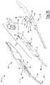
- FIG. 1Ais a perspective view of and electrosurgical device 100 configured as forceps 2 with a blade 90 .
- the blade 90is retracted between the first working arm 30 and the second working arm 32 so that the working arms 30 and 32 are movable.
- the blade 90is connected to a body 10 that carries a shuttle 60 and a first activation button 16 , second activation button 18 , and third activation button 22 .
- the first working arm 30includes a shuttle 60 and the second working arm 32 includes a shuttle 60 and the shuttles each carry a bias device (not shown) that selectively bias the first working arm 30 and second working arm 32 respectively against the body 10 .
- FIG. 1Billustrates an exploded view of the forceps 2 .
- the forceps 2 as shownare also an electrosurgical device 100 .
- the forceps 2include a body 10 with a blade 90 extending therefrom.
- the body 10is partially covered by a movable shuttle 60 (e.g., a second shuttle portion), which moves between a first position (not shown) and a second position (not shown).
- the first working arm 30 and the second working arm 32are substantially a mirror image of each other.
- Both the first working arm 30 and the second working arm 32include a pivot 37 with a pivot point 36 , which as shown is a pin, that the working arms move about to create a gripping force.
- the pivot point 36extends through a pair of opposing bosses 34 on each of the working arms.
- Each of the working armsinclude a bias device 80 , riding on a shuttle 60 (e.g., a first shuttle first portion and a first shuttle second portion), that assists in opening the working arms 30 , 32 .
- the bias devices 80includes a free end 82 and a constrained end 84 .
- the free end 82contacts a contact zone 66 of the shuttle 60 when the shuttle 60 is in a first position.
- the bias devices 80include breaks 88 that assist in resiliently biasing the working arms 30 , 32 .
- Each of the working arms 30 , 32include an electrical path 38 so that power travels to electrodes 33 at ends of each respective working arm 30 , 32 .
- the body 10includes a first activation button 16 , a second activation button 18 , and a third activation button 22 .
- the body 10has a deactivation feature 14 , which as shown is a through hole, in the inner shell 12 of the body 10 .
- FIG. 2illustrates forceps 2 where the first working arm 30 and the second working 32 include a cross over 42 so that distal ends of the first working arm 30 and the second working arm 32 are biased closed.
- the forceps 2include a body 10 having handle 20 connected to a gripping portion 44 with a distal end 40 extending beyond the gripping portion 44 .
- the first working arm 30 and the second working arm 32are biased towards the body 10 and ends of the first working arm 30 and the second working arm 32 open.
- the bias devices 80 on the shuttles 60bias the working arms 30 , 32 closed by the bias devices 80 biasing off of the shuttle 60 on the body 10 .
- a blade 90is connected to the shuttle 60 so that movement of the shuttle moves the blade 90 between the first working arm 30 and the second working arm 32 towards and away from the distal end (i.e. the tip) 40 . As shown, the blade 90 is extending beyond the first working arm 30 and the second working arm 32 .
- FIG. 3illustrates of the forceps 2 of FIG. 2 with the body removed.
- the first working arm 30 , the second working arm 32 , and the blade 90are fully visible. Ends of the first working arm 30 and the second working arm 32 are connected together to assist in creating a bias force.
- An electrode 33is located at ends of the first working arm 30 and the second working arm 32 so that bipolar energy can be supplied between the first working arm 30 and the second working arm 32 .
- An electrode 33is located on the blade 90 so that monopolar energy can be supplied through the blade 90 .
- FIG. 4illustrates the forceps 2 with a first working arm 30 and a second working 32 with a body 10 located therebetween.
- a bias device 80is located on a first side of the body 10 proximate to the first working arm 30 and a bias device 80 is located on a second side of the body 10 proximate to the second working arm 32 .
- the body 10is in communication with a blade 90 that is extended distal of the first working arm 30 and the second working arm 32 .
- the first working arm 30 and the second working arm 32both include a shuttle 60 that are located in a second position 60 B so that a gap (G) is located between the first working arm 30 and the bias device 80 on the first side of the body 10 and a gap (G) is located between the second working arm 32 and the bias device 80 on the second side of the body 10 .
- the gaps (G)are sufficiently large so that the first working arm 30 and the second working arm 32 are not biased by a respective bias device 80 when a force is applied to the first working arm 30 or the second working arm 32 .
- FIG. 5illustrates the forceps 2 with a first working arm 30 and a second working arm 32 with a body 10 located therebetween.
- a bias device 80is located on a first side of the body 10 proximate to the first working arm 30 and a bias device 80 is located on a second side of the body 10 proximate to the second working arm 32 .
- the body 10is in communication with a blade 90 that is extended distal of the first working arm 30 and second working arm 32 .
- the shuttle 60 on first working arm 30is located in a first position 60 A
- the shuttle 60 on the second working arm 32is located in a second position 60 B.
- a deactivation feature 14which is a gap (G), is located between the second working arm 32 and the bias device 80 on the second side of the body 10 so that the bias device 80 is free of contact with the second working arm 32 and second working arm 32 is not biased.
- the shuttle 60 on the first working arm 30fills the gap located between the first working arm 30 and the bias device 80 so that the first working arm 30 is biased by the bias device 80 contacting the shuttle 60 on the first working arm.
- the shuttle 60 on the first working arm 30fills the gap located between the first working arm 30 and the bias device 80 so that the first working arm 30 is biased by the bias device 80 contacting the shuttle 60 on the first working arm 30 .
- a gap (G)is located between the bias device 80 and the second working arm 32 so that the second working arm 32 is not biased.
- FIG. 7illustrates the forceps 2 with a first working arm 30 and a second working arm 32 with a body 10 located therebetween.
- a bias device 80is located on a first side of the body 10 proximate to the first working arm 30 and a bias device 80 is located on a second side of the body 10 proximate to the second working arm 32 .
- the body 10is in communication with a blade 90 that, as shown, is extended distal of the first working arm 30 and the second working arm 32 .
- the shuttle 60 on the first working arm 30is in a second position 60 B and the shuttle 60 on the second working arm 32 is in a first position 60 A.
- a gap (G)is located between the shuttle 60 on the first working arm 30 and the bias device 80 on the first side of the body 10 and no gap is located between the second working arm 32 and the bias device 80 on the second side of the body 10 so only the second working arm 32 is biased and the first working arm 30 is free of bias.
- FIG. 8illustrates the forceps 2 with a first working arm 30 and a second working arm 32 with a body 10 located therebetween.
- a shuttle 60is movably connected to the body 10 and is shown in the first position 60 A.
- a bias device 80is located on a first side of the body 10 proximate to the first working arm 30 and a bias device 80 is located on a second side of the body 10 proximate to the second working arm 32 .
- the body 10is in communication with a blade 90 that is extended distal of the first working arm 30 and the second working arm 32 .
- a shuttle 60is located on the first working arm 30 in a second position 60 B forming a gap (G) between the first working arm 30 and the bias device 80 so that the first working arm 30 is not biased.
- a shuttle 60is located on the second working arm 32 in a first position 60 A so that the bias device 80 on the shuttle 60 of the body 10 aligns with the shuttle 60 on the second working arm 32 and the bias device 80 biases the second working arm 32
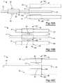
- FIG. 9illustrates the forceps 2 with a first working arm 30 and a second working arm 32 with a body 10 located therebetween.
- a body 10is in communication with a blade 90 and the blade 90 is retracted so that a distal end 62 of the blade is flush with the distal ends 62 of the first working arm 30 and the second working arm 32 .
- a bias device 80is connected to the body 10 and is located on a first side of the body 10 proximate to the first working arm 30 so that when the bias device 80 contacts the shuttle 60 on the first working arm 30 , the first working arm 30 is biased.
- a bias device 80is connected to the blade 90 and is located on a second side of the body 10 proximate to the second working arm 32 so that when the bias device 80 contacts the shuttle 60 on the second working arm 32 , the second working arm 32 is biased. Both the shuttle 60 on the first working arm 30 and the shuttle 60 on the second working arm 32 are located in a first position 60 A.
- FIG. 10Aillustrates the forceps 2 with a first working arm 30 and a second working arm 32 with a body 10 located there between.
- the body 10is in communication a blade 90 that is fully retracted allowing the first working arm 30 and the second working arm 32 full movement.
- the first working arm 30includes a shuttle 60 in a first position 60 A and the second working arm 32 includes a shuttle 60 in a first position 60 A.
- a shuttle 60is in communication with the body 10 and the blade 90 .
- a bias device 80is carried on the shuttle 60 on a first side proximate the first working arm 30 and on a second side proximate the second working arm 32 .
- the shuttle 60 on the body 10is in a third position 60 C with blade fully retracted so that a gap (G) is located between the bias devices 80 and the first working arm 30 and second working arm 32 respectively.
- FIG. 10Billustrates the forceps 2 with a first working arm 30 and a second working arm 32 with a body 10 located therebetween.
- the body 10is in communication with a blade 90 that has a distal end 62 that is flush with the distal ends 62 of the first working arm 30 and the second working arm 32 .
- the first working arm 30includes a shuttle 60 in a first position 60 A and the second working arm 32 includes a shuttle in a first position 60 A.
- a shuttle 60carrying a bias device 80 on a first side and a bias device 80 on a second side, is located on the body 10 and the shuttle 60 is located in the first position 60 A so that the bias devices 80 align with the shuttles 60 on the first working arm 30 and the second working arm 32 to bias the first working arm 30 and the second working arm 32 respectively.
- FIG. 10Cillustrates the forceps 2 with a first working arm 30 and a second working arm 32 with a body 10 located therebetween.
- the body 10is in communication a blade 90 that is fully retracted allowing the first working arm 30 and the second working arm 32 full movement.
- the first working arm 30includes a shuttle 60 in a first position 60 A and the second working arm 32 includes a shuttle in a first position 60 A.
- a shuttle 60is in communication with the body 10 and the blade 90 .
- a bias device 80is carried on the shuttle 60 on a first side proximate the first working arm 30 and on a second side proximate the second working arm 32 .
- the shuttle 60 on the body 10is in a first position 60 A with blade fully retracted so that the bias devices 80 align with the shuttles 60 on the first working arm 30 and the second working arm 32 respectively to create a bias force.
- FIG. 10Dillustrates the forceps 2 with a first working arm 30 and a second working arm 32 with a body 10 located therebetween.
- a shuttle 60e.g. a first shuttle portion
- a shuttle 60e.g., a third shuttle first portion
- a shuttle 60is located on the body 10 in a first position 60 A so that a bias device 80 carried on the shuttle 60 is aligned with the shuttle 60 on the first working arm 30 so that the bias device 80 biases the first working arm 30 .
- a shuttle 60e.g., a second shuttle portion
- a second shuttle 60(e.g., a third shuttle second portion) carrying a bias device 80 is located on the body 10 and/or blade 90 opposite the second working arm 32 and the second shuttle 60 is in a second position 60 B so that a gap (G) is located between the bias device 80 and the shuttle 60 on the second working arm 32 so that the bias device 60 does not bias the second working arm 32 .
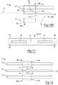
- FIG. 11illustrates a side view of the second working arm 32 , the first working arm 30 being a mirror image of the second working arm 32 .
- the working armsinclude a distal end 62 and a proximal end 64 .
- FIG. 12illustrates the forceps 2 with a first working arm 30 and a second working arm 32 with a body 10 located therebetween.
- the body 10is connected to a blade 90 that extends from the body 10 .
- the body 10includes a deactivation feature 14 proximate to the first working arm 30 and a deactivation feature 14 proximate to the second working arm 32 .
- the first working arm 30includes a shuttle 60 with a bias device 80 , the shuttle 60 being movable between a first position 60 A and a second position (not shown). In the first position 60 A, the shuttle 60 proximate to the first working arm 30 and the shuttle 60 proximate to the second working arm 32 align the bias devices 80 with the body 10 so that the first working arm 30 and the second working arm 32 bias against the body 10 .
- FIG. 13illustrates the forceps 2 with a first working arm 30 and a second working arm 32 with a body 10 located therebetween.
- the body 10is connected to a blade 90 that extends from the body 10 .
- the body 10includes a bias device 80 proximate to the first working arm 30 and a bias device 80 proximate to the second working arm 32 .
- the first working arm 30includes a shuttle 60 with a deactivation feature 14 , the shuttle 60 moving between a first position (not shown) and a second position 60 B. In the second position 60 B, the shuttle 60 proximate to the first working arm 30 aligns the deactivation feature 14 with the bias member 80 so that the first working arm is not biased.
- FIG. 14illustrates the forceps 2 with a first working arm 30 and a second working arm 32 with a body 10 located therebetween.
- the body 10includes a blade 90 extending therefrom.
- the body 10includes a bias device 80 proximate to the first working arm 30 and a bias device 80 proximate to the second working arm 32 .
- the first working arm 30includes a deactivation feature 14 and a shuttle 60 which moves between a first position 60 A and a second position (not shown). In the first position 60 A, the shuttle 60 proximate to the first working arm 30 covers the deactivation feature 14 so the bias device 80 on the body 10 biases against the shuttle 60 on the first working arm 30 .
- the second working arm 32includes a deactivation feature 14 and a shuttle 60 which moves between a first position (not shown) and a second position 60 B. In the second position 60 B, the shuttle 60 proximate to the second working arm 32 uncovers the deactivation feature 14 so the bias device 80 is aligned with the deactivation feature 80 preventing the second working arm 32 or the shuttle 60 from biasing against the bias device 80 on the body 10 .
- FIG. 15illustrates the forceps 2 with a first working arm 30 and a second working arm 32 with a body 10 located therebetween.
- the body 10includes a blade 90 extending therefrom.
- the first working arm 30includes a bias device 80 and a shuttle 60 which moves between a first position (not shown) and a second position 60 B.
- the shuttle 60 in the second position 60 Bslides over the bias device 80 so that the shuttle 60 compresses the bias device 80 and deactivates the bias device 80 so that the first working arm is free from biasing relative to the body 10 .
- the second working arm 32includes a bias device 80 and a shuttle 60 which moves between a first position 60 A and a second position (not shown).
- the shuttle 60 in the first position 60 Ais not in contact with the bias device 80 so that the bias device 80 is in communication with the body 10 and the bias device 80 of the second working arm 32 biases against the body 10 .
- any numerical values recited hereininclude all values from the lower value to the upper value in increments of one unit provided that there is a separation of at least 2 units between any lower value and any higher value.
- the amount of a component or a value of a process variablesuch as, for example, temperature, pressure, time and the like is, for example, from 1 to 90, preferably from 20 to 80, more preferably from 30 to 70, it is intended that values such as 15 to 85, 22 to 68, 43 to 51, 30 to 32 etc. are expressly enumerated in this specification.
- one unitis considered to be 0.0001, 0.001, 0.01 or 0.1 as appropriate.
Landscapes
- Health & Medical Sciences (AREA)
- Engineering & Computer Science (AREA)
- Surgery (AREA)
- Life Sciences & Earth Sciences (AREA)
- Biomedical Technology (AREA)
- Public Health (AREA)
- Nuclear Medicine, Radiotherapy & Molecular Imaging (AREA)
- Veterinary Medicine (AREA)
- General Health & Medical Sciences (AREA)
- Heart & Thoracic Surgery (AREA)
- Medical Informatics (AREA)
- Molecular Biology (AREA)
- Animal Behavior & Ethology (AREA)
- Mechanical Engineering (AREA)
- Physics & Mathematics (AREA)
- Otolaryngology (AREA)
- Plasma & Fusion (AREA)
- Ophthalmology & Optometry (AREA)
- Surgical Instruments (AREA)
Abstract
Description
- 2 Forceps
- 10 Body
- 12 Inner shell
- 14 Deactivation feature
- 16 First activation button
- 18 Second activation button
- 20 Handle
- 30 First working arm
- 32 Second working arm
- 33 Electrode
- 34 Boss
- 36 Pivot pin
- 37 Pivot
- 38 Electrical path
- 40 Distal end
- 42 Cross Over
- 44 Gripping portion
- 60 Shuttle
- 60A First position
- 60B Second position
- 60C Third position
- 62 Distal end
- 64 Proximal end
- 66 Contact Zone
- 80 Bias device
- 82 Free end
- 84 Constrained end
- 86 Contact portion of spring
- 88 Breaks
- 90 Blade
- 100 Electrosurgical Device
Claims (21)
Priority Applications (1)
| Application Number | Priority Date | Filing Date | Title |
|---|---|---|---|
| US15/801,583US11298801B2 (en) | 2017-11-02 | 2017-11-02 | Bias device for biasing a gripping device including a central body and shuttles on the working arms |
Applications Claiming Priority (3)
| Application Number | Priority Date | Filing Date | Title |
|---|---|---|---|
| US15/801,533US10667834B2 (en) | 2017-11-02 | 2017-11-02 | Bias device for biasing a gripping device with a shuttle on a central body |
| US15/801,379US11383373B2 (en) | 2017-11-02 | 2017-11-02 | Bias device for biasing a gripping device by biasing working arms apart |
| US15/801,583US11298801B2 (en) | 2017-11-02 | 2017-11-02 | Bias device for biasing a gripping device including a central body and shuttles on the working arms |
Related Parent Applications (1)
| Application Number | Title | Priority Date | Filing Date |
|---|---|---|---|
| US15/801,379Continuation-In-PartUS11383373B2 (en) | 2017-11-02 | 2017-11-02 | Bias device for biasing a gripping device by biasing working arms apart |
Publications (2)
| Publication Number | Publication Date |
|---|---|
| US20190126442A1 US20190126442A1 (en) | 2019-05-02 |
| US11298801B2true US11298801B2 (en) | 2022-04-12 |
Family
ID=66245990
Family Applications (1)
| Application Number | Title | Priority Date | Filing Date |
|---|---|---|---|
| US15/801,583Active2040-01-31US11298801B2 (en) | 2017-11-02 | 2017-11-02 | Bias device for biasing a gripping device including a central body and shuttles on the working arms |
Country Status (1)
| Country | Link |
|---|---|
| US (1) | US11298801B2 (en) |
Cited By (1)
| Publication number | Priority date | Publication date | Assignee | Title |
|---|---|---|---|---|
| US12257690B2 (en) | 2017-11-02 | 2025-03-25 | Gyrus Acmi, Inc. | Bias device for biasing a gripping device by biasing working arms apart |
Families Citing this family (3)
| Publication number | Priority date | Publication date | Assignee | Title |
|---|---|---|---|---|
| US10667834B2 (en) | 2017-11-02 | 2020-06-02 | Gyrus Acmi, Inc. | Bias device for biasing a gripping device with a shuttle on a central body |
| US11717338B2 (en) | 2018-09-10 | 2023-08-08 | Jgmg Bengochea, Llc | Bipolar dissector |
| US20250284350A1 (en)* | 2024-03-07 | 2025-09-11 | Imam Abdulrahman Bin Faisal University | Smart stylus for hand rehabilation therapy |
Citations (291)
| Publication number | Priority date | Publication date | Assignee | Title |
|---|---|---|---|---|
| US1198958A (en) | 1915-07-12 | 1916-09-19 | Cleveland Dental Mfg Company | Tweezers. |
| US2042985A (en) | 1934-08-22 | 1936-06-02 | Albert B Gardella | Tweezers |
| US2214984A (en) | 1938-04-07 | 1940-09-17 | Bachmann Henry | Tweezers |
| US2381084A (en) | 1943-07-15 | 1945-08-07 | Lillian Catherine Slad | Tweezers |
| US2575652A (en) | 1947-08-19 | 1951-11-20 | Ransom Y Bovee | Pocket tweezer article |
| US2894424A (en) | 1958-04-24 | 1959-07-14 | Jr Charles Swoope Vaughan | Tweezer type wire stripping tool having an adjustable stop and stop latching means |
| US3399583A (en) | 1966-12-09 | 1968-09-03 | Hall Gordon Lance | Locking tweezers |
| US3417752A (en) | 1965-11-12 | 1968-12-24 | Byron C. Butler | Magnetic clamp closing device for use with surgical instruments |
| US3465621A (en) | 1967-11-29 | 1969-09-09 | Ladd Res Ind | Locking tweezers |
| US3576072A (en) | 1969-09-29 | 1971-04-27 | James Bernard Turner Foster | Surgical instrument |
| US3643663A (en) | 1968-10-16 | 1972-02-22 | F L Fischer | Coagulating instrument |
| US3685518A (en) | 1970-07-29 | 1972-08-22 | Aesculap Werke Ag | Surgical instrument for high-frequency surgery |
| US3699632A (en) | 1971-07-30 | 1972-10-24 | Itt | Overriding latch mechanism |
| US3818784A (en) | 1973-01-03 | 1974-06-25 | Scient Components Inc | Changeable tip tweezers and the like |
| US3906957A (en) | 1973-04-24 | 1975-09-23 | Ici Ltd | Forceps |
| US3913586A (en) | 1974-01-28 | 1975-10-21 | Gomco Surgical Mfg Co | Hemostat |
| US4023450A (en) | 1976-02-19 | 1977-05-17 | Goran Ygfors | Pliers of plastic |
| US4041952A (en) | 1976-03-04 | 1977-08-16 | Valleylab, Inc. | Electrosurgical forceps |
| US4154226A (en) | 1977-04-20 | 1979-05-15 | Coloplast International A/S | Magnetically operated closure for an intestinal orifice |
| US4171700A (en) | 1976-10-13 | 1979-10-23 | Erbe Elektromedizin Gmbh & Co. Kg | High-frequency surgical apparatus |
| US4202337A (en) | 1977-06-14 | 1980-05-13 | Concept, Inc. | Bipolar electrosurgical knife |
| US4318313A (en) | 1980-03-10 | 1982-03-09 | Tartaglia John A | Tweezer forceps |
| US4375218A (en) | 1981-05-26 | 1983-03-01 | Digeronimo Ernest M | Forceps, scalpel and blood coagulating surgical instrument |
| US4387610A (en) | 1980-04-03 | 1983-06-14 | Amp Incorporated | Chordal mechanism |
| US4407069A (en) | 1981-12-08 | 1983-10-04 | The Scott & Fetzer Company | Scissors with cushioned stop |
| US4418692A (en) | 1978-11-17 | 1983-12-06 | Guay Jean Louis | Device for treating living tissue with an electric current |
| US4443935A (en) | 1982-03-01 | 1984-04-24 | Trident Surgical Corporation | Process for making electrosurgical scalpel pencil |
| US4452106A (en)* | 1982-01-22 | 1984-06-05 | Tartaglia John A | Tool having articulated opposing jaws |
| US4462404A (en) | 1981-01-31 | 1984-07-31 | Vormals Jetter & Scheerer Aesculap-Werke Aktiengesellschaft | Forceps- or tweezers-shaped surgical instrument |
| US4463759A (en) | 1982-01-13 | 1984-08-07 | Garito Jon C | Universal finger/foot switch adaptor for tube-type electrosurgical instrument |
| US4492832A (en) | 1982-12-23 | 1985-01-08 | Neomed, Incorporated | Hand-controllable switching device for electrosurgical instruments |
| US4492231A (en) | 1982-09-17 | 1985-01-08 | Auth David C | Non-sticking electrocautery system and forceps |
| US4494543A (en) | 1982-03-05 | 1985-01-22 | Hart Ernest D | Instrument for extracting splinters |
| US4504707A (en) | 1982-03-15 | 1985-03-12 | Kyushu Hitachi Maxell, Ltd. | Push-button switch locking device for use in electric appliance |
| US4524648A (en) | 1984-08-17 | 1985-06-25 | Chung Charng J | Fixation tweezers |
| US4552143A (en) | 1981-03-11 | 1985-11-12 | Lottick Edward A | Removable switch electrocautery instruments |
| US4655215A (en) | 1985-03-15 | 1987-04-07 | Harold Pike | Hand control for electrosurgical electrodes |
| US4669470A (en) | 1985-11-20 | 1987-06-02 | Brandfield Robert T | Surgical forceps/scissors |
| US4686980A (en) | 1986-04-17 | 1987-08-18 | Alcon Laboratories, Inc. | Disposable bipolar instrument |
| US4713885A (en) | 1986-12-08 | 1987-12-22 | Ronald Keklak | Safe utility knife |
| US4757612A (en) | 1985-03-21 | 1988-07-19 | Preposreve S.A.R.L. | Fixed-blade knife with retractable blade cover |
| US4784136A (en) | 1987-01-12 | 1988-11-15 | Peter Klein | Electrical epilation |
| US4839947A (en) | 1988-07-14 | 1989-06-20 | Robert Cohen | Clamp mechanism |
| US4860745A (en) | 1986-07-17 | 1989-08-29 | Erbe Elektromedizin Gmbh | High frequency electrosurgical apparatus for thermal coagulation of biologic tissues |
| US4896661A (en) | 1988-02-05 | 1990-01-30 | Pfizer, Inc. | Multi purpose orthopedic ratcheting forceps |
| US4935027A (en) | 1989-08-21 | 1990-06-19 | Inbae Yoon | Surgical suture instrument with remotely controllable suture material advancement |
| EP0392548A1 (en) | 1989-04-14 | 1990-10-17 | CODMAN & SHURTLEFF INC. | Multi-position latching mechanism for forceps |
| US5021616A (en) | 1989-11-03 | 1991-06-04 | Compaq Computer Corporation | Switch cover |
| US5035695A (en) | 1987-11-30 | 1991-07-30 | Jaroy Weber, Jr. | Extendable electrocautery surgery apparatus and method |
| US5071426A (en) | 1989-04-06 | 1991-12-10 | Stuart Dolgin | Surgical scalpel with retractable blade guard |
| US5104397A (en) | 1989-04-14 | 1992-04-14 | Codman & Shurtleff, Inc. | Multi-position latching mechanism for forceps |
| US5108392A (en) | 1987-06-17 | 1992-04-28 | United States Surgical Corporation | Coagulation forceps and method of fabricating the same |
| US5147378A (en) | 1991-03-05 | 1992-09-15 | Harold Markham | Grapsing forceps |
| US5176702A (en) | 1991-04-04 | 1993-01-05 | Symbiosis Corporation | Ratchet locking mechanism for surgical instruments |
| US5190541A (en) | 1990-10-17 | 1993-03-02 | Boston Scientific Corporation | Surgical instrument and method |
| US5196009A (en) | 1991-09-11 | 1993-03-23 | Kirwan Jr Lawrence T | Non-sticking electrosurgical device having nickel tips |
| US5207696A (en) | 1992-04-30 | 1993-05-04 | Medical Sterile Products, Inc. | Surgical scalpel |
| US5207691A (en) | 1991-11-01 | 1993-05-04 | Medical Scientific, Inc. | Electrosurgical clip applicator |
| US5208983A (en) | 1991-08-19 | 1993-05-11 | Masse Joseph H | Retracting cutter |
| US5226904A (en) | 1991-02-08 | 1993-07-13 | Conmed Corporation | Electrosurgical instrument |
| US5250056A (en) | 1992-02-04 | 1993-10-05 | Hasson Harrith M | Forceps-type surgical instrument |
| US5281216A (en) | 1992-03-31 | 1994-01-25 | Valleylab, Inc. | Electrosurgical bipolar treating apparatus |
| US5290286A (en) | 1991-11-12 | 1994-03-01 | Everest Medical Corporation | Bipolar instrument utilizing one stationary electrode and one movable electrode |
| US5293878A (en) | 1991-04-04 | 1994-03-15 | Symbiosis Corporation | Endoscopic surgical instruments having stepped rotatable end effectors |
| US5318589A (en) | 1992-04-15 | 1994-06-07 | Microsurge, Inc. | Surgical instrument for endoscopic surgery |
| US5342359A (en) | 1993-02-05 | 1994-08-30 | Everest Medical Corporation | Bipolar coagulation device |
| US5370659A (en) | 1992-04-09 | 1994-12-06 | Olympus Optical Co., Ltd. | Grasping forceps for medical treatment |
| US5403312A (en) | 1993-07-22 | 1995-04-04 | Ethicon, Inc. | Electrosurgical hemostatic device |
| US5413575A (en) | 1994-04-19 | 1995-05-09 | Innovative Medical Technologies, Ltd. | Multifunction electrocautery tool |
| US5423814A (en) | 1992-05-08 | 1995-06-13 | Loma Linda University Medical Center | Endoscopic bipolar coagulation device |
| US5425743A (en) | 1992-04-06 | 1995-06-20 | United States Surgical Corporation | Surgical instrument locking mechanism |
| US5440813A (en) | 1993-06-04 | 1995-08-15 | Roskam; Scott H. | Rideless scissors with an adjustable load transverse to the pivot axis on a pivot joint |
| US5441498A (en) | 1994-02-16 | 1995-08-15 | Envision Surgical Systems, Inc. | Method of using a multimodality probe with extendable bipolar electrodes |
| US5443463A (en) | 1992-05-01 | 1995-08-22 | Vesta Medical, Inc. | Coagulating forceps |
| US5456695A (en) | 1993-10-25 | 1995-10-10 | United States Surgical Corporation | Multi-tool surgical apparatus |
| US5458598A (en) | 1993-12-02 | 1995-10-17 | Cabot Technology Corporation | Cutting and coagulating forceps |
| US5472442A (en) | 1994-03-23 | 1995-12-05 | Valleylab Inc. | Moveable switchable electrosurgical handpiece |
| US5484435A (en) | 1992-01-15 | 1996-01-16 | Conmed Corporation | Bipolar electrosurgical instrument for use in minimally invasive internal surgical procedures |
| US5483952A (en) | 1991-09-26 | 1996-01-16 | United States Surgical Corporation | Handle for surgical instruments |
| US5499998A (en) | 1993-09-14 | 1996-03-19 | Microsurge, Inc. | Endoscoptic surgical instrument with guided jaws and ratchet control |
| US5531744A (en) | 1991-11-01 | 1996-07-02 | Medical Scientific, Inc. | Alternative current pathways for bipolar surgical cutting tool |
| US5540685A (en) | 1995-01-06 | 1996-07-30 | Everest Medical Corporation | Bipolar electrical scissors with metal cutting edges and shearing surfaces |
| US5562503A (en) | 1994-12-05 | 1996-10-08 | Ellman; Alan G. | Bipolar adaptor for electrosurgical instrument |
| US5573424A (en) | 1995-02-09 | 1996-11-12 | Everest Medical Corporation | Apparatus for interfacing a bipolar electrosurgical instrument to a monopolar generator |
| JPH08322847A (en) | 1995-05-31 | 1996-12-10 | Kyocera Corp | Blood coagulation hemostatic device |
| US5619892A (en) | 1994-11-08 | 1997-04-15 | Snap-On Technologies, Inc. | Opening spring for pivoting hand tool |
| US5626577A (en) | 1994-02-28 | 1997-05-06 | Harris; George A. | Manually extendable electrocautery surgical apparatus |
| JPH09122140A (en) | 1995-10-31 | 1997-05-13 | Olympus Optical Co Ltd | Operation device |
| US5658281A (en) | 1995-12-04 | 1997-08-19 | Valleylab Inc | Bipolar electrosurgical scissors and method of manufacture |
| USD386054S (en) | 1996-08-28 | 1997-11-11 | Revlon Consumer Products Corporation | Cuticle nipper |
| US5702390A (en) | 1996-03-12 | 1997-12-30 | Ethicon Endo-Surgery, Inc. | Bioplar cutting and coagulation instrument |
| US5709680A (en) | 1993-07-22 | 1998-01-20 | Ethicon Endo-Surgery, Inc. | Electrosurgical hemostatic device |
| JPH1057390A (en) | 1996-07-18 | 1998-03-03 | Valleylab Inc | Electric surgical instrument and manufacture |
| US5735849A (en) | 1996-11-07 | 1998-04-07 | Everest Medical Corporation | Endoscopic forceps with thumb-slide lock release mechanism |
| US5779701A (en) | 1995-04-27 | 1998-07-14 | Symbiosis Corporation | Bipolar endoscopic surgical scissor blades and instrument incorporating the same |
| US5810805A (en) | 1996-02-09 | 1998-09-22 | Conmed Corporation | Bipolar surgical devices and surgical methods |
| US5827281A (en) | 1996-01-05 | 1998-10-27 | Levin; John M. | Insulated surgical scissors |
| US5884954A (en) | 1997-06-04 | 1999-03-23 | Trozera; Thomas | Locking tweezers for tying fly-fishing hooks |
| US5891140A (en) | 1996-12-23 | 1999-04-06 | Cardiothoracic Systems, Inc. | Electrosurgical device for harvesting a vessel especially the internal mammary artery for coronary artery bypass grafting |
| US5902301A (en) | 1998-02-23 | 1999-05-11 | Everest Medical Corporation | Cutting/coagulating forceps with interleaved electrodes |
| US5922001A (en) | 1989-12-05 | 1999-07-13 | Yoon; Inbae | Surgical instrument with jaws and a movable internal blade member and method for use thereof |
| US5951545A (en) | 1996-07-15 | 1999-09-14 | Gebrueder Berchtold Gmbh & Co. | High-frequency surgical instrument and method of operating the same |
| WO1999066850A1 (en) | 1998-06-22 | 1999-12-29 | Lina Medical Aps | An electrosurgical device for coagulating and for making incisions, a method of severing blood vessels and a method of coagulating and for making incisions in or severing tissue |
| US6024741A (en) | 1993-07-22 | 2000-02-15 | Ethicon Endo-Surgery, Inc. | Surgical tissue treating device with locking mechanism |
| US6030384A (en) | 1998-05-01 | 2000-02-29 | Nezhat; Camran | Bipolar surgical instruments having focused electrical fields |
| JP2000070280A (en) | 1998-09-02 | 2000-03-07 | Olympus Optical Co Ltd | High-frequency treatment implement |
| US6039734A (en) | 1995-10-24 | 2000-03-21 | Gyrus Medical Limited | Electrosurgical hand-held battery-operated instrument |
| JP2000102545A (en) | 1997-06-18 | 2000-04-11 | Eggers & Associates Inc | Electric tweezers for surgery |
| US6050996A (en) | 1997-11-12 | 2000-04-18 | Sherwood Services Ag | Bipolar electrosurgical instrument with replaceable electrodes |
| US6053908A (en) | 1999-01-07 | 2000-04-25 | Design Standards Corporation | Ratchet assembly for surgical instrument |
| US6074386A (en) | 1995-12-29 | 2000-06-13 | Gyrus Medical Limited | Electrosurgical instrument and an electrosurgical electrode assembly |
| US6102909A (en) | 1997-08-26 | 2000-08-15 | Ethicon, Inc. | Scissorlike electrosurgical cutting instrument |
| US6110171A (en)* | 1999-03-09 | 2000-08-29 | Everest Medical Corporation | Electrosurgical cutting and coagulating instrument for open surgery |
| US6113596A (en) | 1996-12-30 | 2000-09-05 | Enable Medical Corporation | Combination monopolar-bipolar electrosurgical instrument system, instrument and cable |
| US6117169A (en) | 1998-06-24 | 2000-09-12 | Sulzer Carbomedics Inc. | Living hinge attachment of leaflet to a valve body |
| US6117158A (en) | 1999-07-07 | 2000-09-12 | Ethicon Endo-Surgery, Inc. | Ratchet release mechanism for hand held instruments |
| US6152923A (en) | 1999-04-28 | 2000-11-28 | Sherwood Services Ag | Multi-contact forceps and method of sealing, coagulating, cauterizing and/or cutting vessels and tissue |
| US6190386B1 (en) | 1999-03-09 | 2001-02-20 | Everest Medical Corporation | Electrosurgical forceps with needle electrodes |
| JP2001170070A (en) | 1999-12-20 | 2001-06-26 | Olympus Optical Co Ltd | Medical treatment instrument |
| US6270497B1 (en) | 1998-08-27 | 2001-08-07 | Olympus Optical Co., Ltd. | High-frequency treatment apparatus having control mechanism for incising tissue after completion of coagulation by high-frequency treatment tool |
| US6273887B1 (en) | 1998-01-23 | 2001-08-14 | Olympus Optical Co., Ltd. | High-frequency treatment tool |
| US6325795B1 (en) | 1996-03-12 | 2001-12-04 | Sherwood Services Ag | Replaceable accessory cord and handswitch |
| US6355032B1 (en) | 1995-06-07 | 2002-03-12 | Arthrocare Corporation | Systems and methods for selective electrosurgical treatment of body structures |
| US6358268B1 (en) | 2000-03-06 | 2002-03-19 | Robert B. Hunt | Surgical instrument |
| US6402747B1 (en) | 1997-07-21 | 2002-06-11 | Sherwood Services Ag | Handswitch cord and circuit |
| US6428538B1 (en) | 1995-10-20 | 2002-08-06 | United States Surgical Corporation | Apparatus and method for thermal treatment of body tissue |
| US20020106609A1 (en) | 2001-02-06 | 2002-08-08 | Palermo Rosanne M. | Dental forceps |
| US20020107517A1 (en) | 2001-01-26 | 2002-08-08 | Witt David A. | Electrosurgical instrument for coagulation and cutting |
| US20020115997A1 (en) | 2000-10-23 | 2002-08-22 | Csaba Truckai | Electrosurgical systems and techniques for sealing tissue |
| US6458128B1 (en) | 2001-01-24 | 2002-10-01 | Ethicon, Inc. | Electrosurgical instrument with a longitudinal element for conducting RF energy and moving a cutting element |
| US6486419B2 (en) | 1998-01-09 | 2002-11-26 | Ricoh Company, Ltd. | Multifunctional image forming apparatus having a covered main power switch |
| US6494886B1 (en) | 2000-06-22 | 2002-12-17 | Granit Medical Innovation, Inc. | Off-set clamp mechanism and associated method for minimally invasive surgery |
| US20030018329A1 (en) | 2000-04-27 | 2003-01-23 | Hooven Michael D. | Transmural ablation device with EKG sensor and pacing electrode |
| US6514252B2 (en) | 1998-05-01 | 2003-02-04 | Perfect Surgical Techniques, Inc. | Bipolar surgical instruments having focused electrical fields |
| US20030050633A1 (en) | 2001-09-13 | 2003-03-13 | Ellman Alan G. | Intelligent selection system for electrosurgical instrument |
| US6551313B1 (en) | 2001-05-02 | 2003-04-22 | John M. Levin | Electrosurgical instrument with separate cutting and coagulating members |
| US20030097126A1 (en) | 1993-05-10 | 2003-05-22 | Arthrocare Corporation | Bipolar electrosurgical clamp for removing and modifying tissue |
| US20030109876A1 (en) | 2001-12-11 | 2003-06-12 | Olympus Optical Co., Ltd. | Instrument for high-frequency treatment and method of high-frequency treatment |
| US20030114850A1 (en) | 2000-09-22 | 2003-06-19 | Tissuelink Medical, Inc. | Fluid-assisted medical device |
| US6585735B1 (en) | 1998-10-23 | 2003-07-01 | Sherwood Services Ag | Endoscopic bipolar electrosurgical forceps |
| US20030144652A1 (en) | 2001-11-09 | 2003-07-31 | Baker James A. | Electrosurgical instrument |
| US6619038B2 (en) | 2000-07-04 | 2003-09-16 | Kanzaki Kokyukoki Mfg. Co., Ltd. | Axle driving apparatus |
| US6623499B1 (en) | 2002-02-21 | 2003-09-23 | Michael Andreini | Retractable safety scalpel |
| US20030181904A1 (en) | 2002-01-23 | 2003-09-25 | Levine Andy H. | Electrosurgical cutting, coagulating and suction instrument |
| US6641595B1 (en) | 1999-08-20 | 2003-11-04 | Surgical Innovations Ltd. | Laparoscopic forceps handle |
| US6679882B1 (en) | 1998-06-22 | 2004-01-20 | Lina Medical Aps | Electrosurgical device for coagulating and for making incisions, a method of severing blood vessels and a method of coagulating and for making incisions in or severing tissue |
| US20040030330A1 (en) | 2002-04-18 | 2004-02-12 | Brassell James L. | Electrosurgery systems |
| US6726686B2 (en) | 1997-11-12 | 2004-04-27 | Sherwood Services Ag | Bipolar electrosurgical instrument for sealing vessels |
| US20040082946A1 (en) | 2002-10-24 | 2004-04-29 | Valley Forge Scientific | Electrosurgical generator apparatus |
| US20040097912A1 (en) | 2002-11-18 | 2004-05-20 | Gonnering Wayne J. | Electrosurgical generator and method with removable front panel having replaceable electrical connection sockets and illuminated receptacles |
| US20040097117A1 (en) | 2002-11-18 | 2004-05-20 | Gonnering Wayne J. | Monopolar electrosurgical multi-plug connector device and method which accepts multiple different connector plugs |
| JP2004147724A (en) | 2002-10-29 | 2004-05-27 | Aisin Kiko Co Ltd | Disposable surgical instrument and its reuse prevention method |
| US6749610B2 (en) | 2002-08-15 | 2004-06-15 | Kirwan Surgical Products, Inc. | Electro-surgical forceps having fully plated tines and process for manufacturing same |
| US6752767B2 (en) | 2002-04-16 | 2004-06-22 | Vivant Medical, Inc. | Localization element with energized tip |
| US6773434B2 (en) | 2001-09-18 | 2004-08-10 | Ethicon, Inc. | Combination bipolar forceps and scissors instrument |
| US6808525B2 (en) | 2001-08-27 | 2004-10-26 | Gyrus Medical, Inc. | Bipolar electrosurgical hook probe for cutting and coagulating tissue |
| US6827717B2 (en) | 2000-08-26 | 2004-12-07 | Olympus Winter & Ibe Gmbh | Monopolar and bipolar electrode for a urological resectoscope |
| US6860882B2 (en) | 2003-02-06 | 2005-03-01 | Codman & Shurtleff, Inc. | Electro-surgical bipolar forceps |
| US20050065510A1 (en) | 2003-08-11 | 2005-03-24 | Yuval Carmel | Electrosurgical device with floating-potential electrodes |
| EP1530952A1 (en) | 2003-11-17 | 2005-05-18 | Sherwood Services AG | Bipolar forceps having monopolar extension |
| US20050113824A1 (en) | 2003-11-20 | 2005-05-26 | Sartor Joe D. | Electrosurgical pencil with improved controls |
| US20050113827A1 (en) | 2003-11-17 | 2005-05-26 | Dumbauld Patrick L. | Bipolar forceps having monopolar extension |
| US20050113825A1 (en) | 1996-09-20 | 2005-05-26 | Ioan Cosmescu | Multifunctional telescopic monopolar/bipolar surgical device and method therefore |
| US20050159745A1 (en) | 2004-01-16 | 2005-07-21 | Surgrx, Inc. | Electrosurgical instrument with replaceable cartridge |
| US20050187512A1 (en) | 2004-02-06 | 2005-08-25 | Isola Scott S. | Ultrasonic probe with detachable slidable cauterization forceps |
| US6942662B2 (en) | 2001-12-27 | 2005-09-13 | Gyrus Group Plc | Surgical Instrument |
| US20050216019A1 (en) | 2002-01-17 | 2005-09-29 | Eckman Walter W | Diskectomy instrument with disposable blade head |
| US20060084973A1 (en) | 2004-10-14 | 2006-04-20 | Dylan Hushka | Momentary rocker switch for use with vessel sealing instruments |
| US7083613B2 (en) | 1997-03-05 | 2006-08-01 | The Trustees Of Columbia University In The City Of New York | Ringed forceps |
| US7094231B1 (en) | 2004-01-22 | 2006-08-22 | Ellman Alan G | Dual-mode electrosurgical instrument |
| US20060190035A1 (en) | 2004-10-08 | 2006-08-24 | Sherwood Services Ag | Latching mechanism for forceps |
| US7108694B2 (en) | 2002-11-08 | 2006-09-19 | Olympus Corporation | Heat-emitting treatment device |
| US20060217701A1 (en) | 2005-03-25 | 2006-09-28 | Boston Scientific Scimed, Inc. | Ablation probe with heat sink |
| WO2006122279A2 (en) | 2005-05-11 | 2006-11-16 | Mayo Foundation For Medical Education And Research | Apparatus and methods for internal surgical procedures |
| US7147637B2 (en) | 2003-12-09 | 2006-12-12 | Gyrus Group Plc | Surgical instrument |
| US7147638B2 (en) | 2003-05-01 | 2006-12-12 | Sherwood Services Ag | Electrosurgical instrument which reduces thermal damage to adjacent tissue |
| US7150749B2 (en) | 2003-06-13 | 2006-12-19 | Sherwood Services Ag | Vessel sealer and divider having elongated knife stroke and safety cutting mechanism |
| US7156846B2 (en) | 2003-06-13 | 2007-01-02 | Sherwood Services Ag | Vessel sealer and divider for use with small trocars and cannulas |
| WO2007002545A1 (en) | 2005-06-22 | 2007-01-04 | Boston Scientific Limited | Steerable medical device control system |
| US20070049922A1 (en) | 2005-08-23 | 2007-03-01 | Daniel Rontal | Retractable electrosurgical electrode |
| US20070078458A1 (en) | 2005-09-30 | 2007-04-05 | Dumbauld Patrick L | Insulating boot for electrosurgical forceps |
| US20070093857A1 (en) | 2005-10-26 | 2007-04-26 | Campbell Rogers | Devices and methods for treating mitral valve regurgitation |
| US20070123855A1 (en) | 2000-12-29 | 2007-05-31 | Intuitive Surgical Inc. | Bipolar cauterizing instrument |
| US20070129716A1 (en) | 2000-12-28 | 2007-06-07 | Derek Daw | Electrosurgical medical system and method |
| US7244257B2 (en) | 2002-11-05 | 2007-07-17 | Sherwood Services Ag | Electrosurgical pencil having a single button variable control |
| EP1810629A2 (en) | 2006-01-24 | 2007-07-25 | Sherwood Services AG | Electrosurgical generator using multiple resonant inductor/capacitor circuits |
| US20070179491A1 (en) | 2006-01-31 | 2007-08-02 | Medtronic, Inc. | Sensing needle for ablation therapy |
| US7252667B2 (en) | 2003-11-19 | 2007-08-07 | Sherwood Services Ag | Open vessel sealing instrument with cutting mechanism and distal lockout |
| US20080033428A1 (en) | 2006-08-04 | 2008-02-07 | Sherwood Services Ag | System and method for disabling handswitching on an electrosurgical instrument |
| US7344536B1 (en) | 2002-02-05 | 2008-03-18 | Origin Medsystems, Inc. | Electrocautery surgical scissors |
| US20080077129A1 (en) | 2006-09-27 | 2008-03-27 | Van Wyk Robert A | Electrosurgical Device Having Floating Potential Electrode and Adapted for Use With a Resectoscope |
| US7377902B2 (en) | 1998-04-08 | 2008-05-27 | Senorx, Inc. | Biopsy anchor device with cutter |
| US20080147092A1 (en) | 2006-10-23 | 2008-06-19 | Michael Rogge | Hybrid energy instrument combined with clip application capability |
| US20080154300A1 (en) | 2006-12-15 | 2008-06-26 | Noel Jabbour | Surgical forceps |
| US20080236860A1 (en) | 2007-04-02 | 2008-10-02 | Prevention Products, Inc. | Electrical switch cover |
| EP1977706A1 (en) | 2007-04-03 | 2008-10-08 | Tyco Healthcare Group, LP | Controller for flexible tissue ablation procedures |
| US20080287948A1 (en) | 2007-05-04 | 2008-11-20 | Gyrus Medical Limited | Electrosurgical system |
| US20090062786A1 (en) | 2007-08-30 | 2009-03-05 | Garito Jon C | Tri-frequency electrosurgical instrument |
| US20090062792A1 (en) | 2007-08-31 | 2009-03-05 | Ethicon Endo-Surgery, Inc. | Electrical ablation surgical instruments |
| US7503917B2 (en) | 2003-11-20 | 2009-03-17 | Covidien Ag | Electrosurgical pencil with improved controls |
| US20090093804A1 (en) | 2007-10-09 | 2009-04-09 | Gyrus Medical Limited, | Electrosurgical system |
| US20090138013A1 (en) | 2004-06-08 | 2009-05-28 | Thorne Jonathan O | Electrosurgical tool with moveable electrode that can be operated in a cutting mode or a coagulation mode |
| US20090138003A1 (en) | 2007-11-28 | 2009-05-28 | Derek Dee Deville | Cordless Medical Cauterization and Cutting Device |
| US20090171147A1 (en) | 2007-12-31 | 2009-07-02 | Woojin Lee | Surgical instrument |
| US20090192509A1 (en) | 2008-01-14 | 2009-07-30 | Curtis Richard J | Electrosurgical system |
| US20090248002A1 (en) | 2008-04-01 | 2009-10-01 | Tomoyuki Takashino | Treatment system, and treatment method for living tissue using energy |
| US7604635B2 (en) | 2000-03-06 | 2009-10-20 | Salient Surgical Technologies, Inc. | Fluid-assisted medical devices, systems and methods |
| US7625391B2 (en) | 2002-11-04 | 2009-12-01 | Stryker Trauma S.A. | Orthopaedic ratcheting forceps |
| US20100042096A1 (en) | 2008-08-18 | 2010-02-18 | Ellman Alan G | MIS electrosurgical handpiece |
| US7674261B2 (en) | 2005-03-28 | 2010-03-09 | Elliquence, Llc | Electrosurgical instrument with enhanced capability |
| US7686827B2 (en) | 2004-10-21 | 2010-03-30 | Covidien Ag | Magnetic closure mechanism for hemostat |
| US20100087814A1 (en) | 2006-06-08 | 2010-04-08 | Kai Desinger | Device for cutting and coagulating tissue |
| US7722607B2 (en) | 2005-09-30 | 2010-05-25 | Covidien Ag | In-line vessel sealer and divider |
| US20100137854A1 (en) | 2008-05-23 | 2010-06-03 | Gyrus Medical Limited | Electrosurgical generator and system |
| US7758577B2 (en) | 2006-12-05 | 2010-07-20 | Ethicon Endo-Surgery, Inc. | Monopolar resection device and method of use |
| US7789878B2 (en) | 2005-09-30 | 2010-09-07 | Covidien Ag | In-line vessel sealer and divider |
| US20100228249A1 (en) | 2009-03-09 | 2010-09-09 | Intuitive Surgical, Inc. | User interfaces for electrosurgical tools in robotic surgical systems |
| WO2010101897A1 (en) | 2009-03-02 | 2010-09-10 | Bovie Medical Corporation | Surgical apparatus for tissue sealing and cutting |
| US7879035B2 (en) | 2005-09-30 | 2011-02-01 | Covidien Ag | Insulating boot for electrosurgical forceps |
| US20110045680A1 (en) | 2007-12-20 | 2011-02-24 | Beller Juergenl | Plug system for surgical devices |
| US7896875B2 (en) | 2004-07-20 | 2011-03-01 | Microline Surgical, Inc. | Battery powered electrosurgical system |
| US20110054462A1 (en) | 2009-08-28 | 2011-03-03 | Ellman Alan G | Electrosurgical instrument with multi-function handpiece |
| US7909820B2 (en) | 2003-03-06 | 2011-03-22 | Salient Surgical Technologies, Inc. | Electrosurgical generator and bipolar electrosurgical device adaptors |
| US20110077648A1 (en) | 2009-09-29 | 2011-03-31 | Tyco Healthcare Group Lp | Switch Assembly for Electrosurgical Instrument |
| US7922718B2 (en) | 2003-11-19 | 2011-04-12 | Covidien Ag | Open vessel sealing instrument with cutting mechanism |
| US7931649B2 (en) | 2002-10-04 | 2011-04-26 | Tyco Healthcare Group Lp | Vessel sealing instrument with electrical cutting mechanism |
| US7931668B2 (en) | 2007-04-26 | 2011-04-26 | Sloat Glenn B | Medical tool with retractible heads |
| US7938469B2 (en) | 2008-10-16 | 2011-05-10 | Commissariat A L'energie Atomique | Tweezers with gripping elements mounted swivelling on branches |
| US20110112530A1 (en) | 2009-11-06 | 2011-05-12 | Keller Craig A | Battery Powered Electrosurgery |
| US7942872B2 (en) | 2006-02-27 | 2011-05-17 | Moshe Ein-Gal | Blended monopolar and bipolar application of RF energy |
| US7955331B2 (en) | 2004-03-12 | 2011-06-07 | Ethicon Endo-Surgery, Inc. | Electrosurgical instrument and method of use |
| US20110178515A1 (en) | 2010-01-15 | 2011-07-21 | Bloom Eliot F | Electrosurgical Devices, Electrosurgical Unit and Methods of Use Thereof |
| US7998140B2 (en) | 2002-02-12 | 2011-08-16 | Salient Surgical Technologies, Inc. | Fluid-assisted medical devices, systems and methods |
| US20110224669A1 (en) | 2010-03-11 | 2011-09-15 | Salient Surgical Technologies, Inc. | Bipolar Electrosurgical Cutter with Position Insensitive Return Electrode Contact |
| US20110251613A1 (en) | 2010-04-12 | 2011-10-13 | Ethicon Endo-Surgery, Inc. | Electrosurgical cutting and sealing instruments with cam-actuated jaws |
| US8062292B1 (en) | 1994-12-13 | 2011-11-22 | Boston Scientific Miami Corporation | Bipolar endoscopic surgical scissor blades and instrument incorporating the same |
| US20110319892A1 (en) | 2009-06-19 | 2011-12-29 | Michael Blomeyer | Electrosurgical pencil switch,circuitry, and method of assembly |
| US8100894B2 (en) | 2002-11-26 | 2012-01-24 | Thermal Corporation | Heat pipe for cautery surgical instrument |
| US20120022530A1 (en) | 2010-07-23 | 2012-01-26 | Ethicon Endo-Surgery, Inc. | Electrosurgical cutting and sealing instrument |
| US20120078292A1 (en) | 2010-03-11 | 2012-03-29 | Olympus Medical Systems Corp. | Surgical forceps |
| US20120095460A1 (en) | 2010-10-18 | 2012-04-19 | Tyco Healthcare Group Lp | Surgical Forceps |
| US8162940B2 (en) | 2002-10-04 | 2012-04-24 | Covidien Ag | Vessel sealing instrument with electrical cutting mechanism |
| US20120101501A1 (en) | 2008-05-15 | 2012-04-26 | Sumitomo Bakelite Co., Ltd. | Endoscopic high-frequency hemostatic forceps |
| US20120123405A1 (en) | 2010-11-16 | 2012-05-17 | Tyco Healthcare Group Lp | Power Glove |
| US20120123409A1 (en) | 2009-03-27 | 2012-05-17 | Micron Shiga, Inc | Medical treatment device |
| US20120150165A1 (en) | 2010-12-10 | 2012-06-14 | Salient Surgical Technologies, Inc. | Bipolar Electrosurgical Device |
| US8216231B2 (en) | 2000-09-15 | 2012-07-10 | Boston Scientific Scimed, Inc. | Methods and systems for focused bipolar tissue ablation |
| US8226649B2 (en) | 2006-07-27 | 2012-07-24 | Applied Medical Resources Corporation | Bipolar electrosurgical scissors |
| US20120202388A1 (en) | 2011-02-09 | 2012-08-09 | Peter Selig | Universal connector socket |
| JP2012517869A (en) | 2009-02-19 | 2012-08-09 | モリア ソシエテ アノニム | Surgical tweezers |
| US8246094B2 (en) | 2010-11-24 | 2012-08-21 | Premier Image Technology (China) Ltd. | Clamping tweezers |
| US8251989B1 (en) | 2006-06-13 | 2012-08-28 | Encision, Inc. | Combined bipolar and monopolar electrosurgical instrument and method |
| US8262655B2 (en) | 2007-11-21 | 2012-09-11 | Ethicon Endo-Surgery, Inc. | Bipolar forceps |
| US20120232553A1 (en) | 2011-03-11 | 2012-09-13 | Salient Surgical Technologies, Inc. | Bronchoscope-Compatible Catheter Provided with Electrosurgical Device |
| US8267935B2 (en) | 2007-04-04 | 2012-09-18 | Tyco Healthcare Group Lp | Electrosurgical instrument reducing current densities at an insulator conductor junction |
| US8287534B2 (en) | 2008-12-09 | 2012-10-16 | Carl Balog | Light emitting electrosurgical scalpel |
| US20120310229A1 (en) | 2011-05-31 | 2012-12-06 | Tyco Healthcare Group Lp | Surgical Device with DC Power Connection |
| US8328170B2 (en) | 2009-06-19 | 2012-12-11 | Toyota Motor Engineering & Manufacturing North America , Inc. | Clamping apparatus |
| US20130066317A1 (en) | 2011-09-08 | 2013-03-14 | Arthrocare Corporation | Plasma bipolar forceps |
| US20130079762A1 (en) | 2011-09-28 | 2013-03-28 | Tyco Healthcare Group Lp | Electrosurgical Instrument |
| US20130178852A1 (en) | 2012-01-06 | 2013-07-11 | Tyco Healthcare Group Lp | Monopolar Pencil With Integrated Bipolar/Ligasure Tweezers |
| US8485413B2 (en) | 2009-02-05 | 2013-07-16 | Ethicon Endo-Surgery, Inc. | Surgical stapling instrument comprising an articulation joint |
| US8491626B2 (en) | 2010-06-02 | 2013-07-23 | Covidien Lp | Apparatus for performing an electrosurgical procedure |
| US8496603B2 (en) | 2005-06-27 | 2013-07-30 | The Trustees Of Dartmough College | Wire torque apparatus, wire insertion devices, improved aneurysm clips and improved aneurysm clip applicators |
| US20130237982A1 (en) | 2010-11-08 | 2013-09-12 | Bovie Medical Corporation | Multi-mode electrosurgical apparatus |
| US8555754B2 (en) | 2010-12-06 | 2013-10-15 | Js Products, Inc. | Biased pliers |
| US8568411B2 (en) | 2008-03-31 | 2013-10-29 | Applied Medical Resources Corporation | Electrosurgical system |
| US20130296846A1 (en) | 2010-11-02 | 2013-11-07 | U.S. Patent Innovations, LLC | System and Method for Electrosurgical Conductive Gas Cutting for Improving Eschar, Sealing Vessels and Tissues |
| US8628529B2 (en) | 2010-10-26 | 2014-01-14 | Ethicon Endo-Surgery, Inc. | Surgical instrument with magnetic clamping force |
| US8632553B2 (en) | 2004-04-07 | 2014-01-21 | Olympus Corporation | Ligature and suture device for medical application, and ligaturing and suturing method for medical application |
| US8702700B2 (en) | 2010-10-20 | 2014-04-22 | Terumo Cardiovascular Systems Corporation | Surgical treatment device |
| US8702691B2 (en) | 2005-10-19 | 2014-04-22 | Thermage, Inc. | Treatment apparatus and methods for delivering energy at multiple selectable depths in tissue |
| WO2014096815A2 (en) | 2012-12-20 | 2014-06-26 | Gerard Michael Brooke | Surgical forceps |
| US20140236202A1 (en) | 2008-11-06 | 2014-08-21 | Covidien Ag | Method for Operating a Two-Stage Switch for Surgical Device |
| US20140276799A1 (en) | 2013-03-15 | 2014-09-18 | GYRUS ACMI, INC., d/b/a Olympus Surgical Technologies America | Combination electrosurgical device |
| US20140276796A1 (en) | 2013-03-15 | 2014-09-18 | GYRUS ACMI, INC., d/b/a Olympus Surgical Technologies America | Combination electrosurgical device |
| US20140276794A1 (en) | 2013-03-15 | 2014-09-18 | GYRUS ACMI, INC., d/b/a Olympus Surgical Technologies America | Electrosurgical instrument |
| US20140276804A1 (en) | 2013-03-15 | 2014-09-18 | GYRUS ACMI, INC., d/b/a Olympus Surgical Technologies America | Offset forceps |
| US20140276798A1 (en) | 2013-03-15 | 2014-09-18 | GYRUS ACMI, INC., d/b/a Olympus Surgical Technologies America | Hand switched combined electrosurgical monopolar and bipolar device |
| US8882756B2 (en) | 2007-12-28 | 2014-11-11 | Medtronic Advanced Energy Llc | Fluid-assisted electrosurgical devices, methods and systems |
| US8939972B2 (en) | 2011-05-06 | 2015-01-27 | Covidien Lp | Surgical forceps |
| US20150320485A1 (en) | 2014-05-12 | 2015-11-12 | GYRUS ACMI, INC., d/b/a Olympus Surgical Technologies America | Resistively heated electrosurgical device |
| US9204879B2 (en) | 2012-06-28 | 2015-12-08 | Ethicon Endo-Surgery, Inc. | Flexible drive member |
| US20160051314A1 (en) | 2014-08-20 | 2016-02-25 | GYRUS ACMI, INC., d/b/a Olympus Surgical Technologies America | Multi-mode combination electrosurgical device |
| US9320563B2 (en) | 2010-10-01 | 2016-04-26 | Applied Medical Resources Corporation | Electrosurgical instruments and connections thereto |
| US9326810B2 (en) | 2010-11-08 | 2016-05-03 | Bovie Medical Corporation | Multi-button electrosurgical apparatus |
| US9345534B2 (en) | 2010-10-04 | 2016-05-24 | Covidien Lp | Vessel sealing instrument |
| US9439665B2 (en) | 2012-12-20 | 2016-09-13 | Covidien Lp | Pediatric combination surgical device |
| US9763685B2 (en) | 2015-01-09 | 2017-09-19 | Gyrus Acmi, Inc. | Combination medical device |
| US20190125376A1 (en) | 2017-11-02 | 2019-05-02 | GYRUS ACMI, INC., d/b/a Olympus Surgical Technologies America | Bias device for biasing a gripping device with a shuttle on a central body |
| US20190126458A1 (en) | 2017-11-02 | 2019-05-02 | GYRUS ACMI, INC., d/b/a Olympus Surgical Technologies America | Bias device for biasing a gripping device by biasing working arms apart |
- 2017
- 2017-11-02USUS15/801,583patent/US11298801B2/enactiveActive
Patent Citations (323)
| Publication number | Priority date | Publication date | Assignee | Title |
|---|---|---|---|---|
| US1198958A (en) | 1915-07-12 | 1916-09-19 | Cleveland Dental Mfg Company | Tweezers. |
| US2042985A (en) | 1934-08-22 | 1936-06-02 | Albert B Gardella | Tweezers |
| US2214984A (en) | 1938-04-07 | 1940-09-17 | Bachmann Henry | Tweezers |
| US2381084A (en) | 1943-07-15 | 1945-08-07 | Lillian Catherine Slad | Tweezers |
| US2575652A (en) | 1947-08-19 | 1951-11-20 | Ransom Y Bovee | Pocket tweezer article |
| US2894424A (en) | 1958-04-24 | 1959-07-14 | Jr Charles Swoope Vaughan | Tweezer type wire stripping tool having an adjustable stop and stop latching means |
| US3417752A (en) | 1965-11-12 | 1968-12-24 | Byron C. Butler | Magnetic clamp closing device for use with surgical instruments |
| US3399583A (en) | 1966-12-09 | 1968-09-03 | Hall Gordon Lance | Locking tweezers |
| US3465621A (en) | 1967-11-29 | 1969-09-09 | Ladd Res Ind | Locking tweezers |
| US3643663A (en) | 1968-10-16 | 1972-02-22 | F L Fischer | Coagulating instrument |
| US3576072A (en) | 1969-09-29 | 1971-04-27 | James Bernard Turner Foster | Surgical instrument |
| US3685518A (en) | 1970-07-29 | 1972-08-22 | Aesculap Werke Ag | Surgical instrument for high-frequency surgery |
| US3699632A (en) | 1971-07-30 | 1972-10-24 | Itt | Overriding latch mechanism |
| US3818784A (en) | 1973-01-03 | 1974-06-25 | Scient Components Inc | Changeable tip tweezers and the like |
| US3906957A (en) | 1973-04-24 | 1975-09-23 | Ici Ltd | Forceps |
| US3913586A (en) | 1974-01-28 | 1975-10-21 | Gomco Surgical Mfg Co | Hemostat |
| US4023450A (en) | 1976-02-19 | 1977-05-17 | Goran Ygfors | Pliers of plastic |
| US4041952A (en) | 1976-03-04 | 1977-08-16 | Valleylab, Inc. | Electrosurgical forceps |
| US4171700A (en) | 1976-10-13 | 1979-10-23 | Erbe Elektromedizin Gmbh & Co. Kg | High-frequency surgical apparatus |
| US4154226A (en) | 1977-04-20 | 1979-05-15 | Coloplast International A/S | Magnetically operated closure for an intestinal orifice |
| US4202337A (en) | 1977-06-14 | 1980-05-13 | Concept, Inc. | Bipolar electrosurgical knife |
| US4418692A (en) | 1978-11-17 | 1983-12-06 | Guay Jean Louis | Device for treating living tissue with an electric current |
| US4318313A (en) | 1980-03-10 | 1982-03-09 | Tartaglia John A | Tweezer forceps |
| US4387610A (en) | 1980-04-03 | 1983-06-14 | Amp Incorporated | Chordal mechanism |
| US4462404A (en) | 1981-01-31 | 1984-07-31 | Vormals Jetter & Scheerer Aesculap-Werke Aktiengesellschaft | Forceps- or tweezers-shaped surgical instrument |
| US4552143A (en) | 1981-03-11 | 1985-11-12 | Lottick Edward A | Removable switch electrocautery instruments |
| US4375218A (en) | 1981-05-26 | 1983-03-01 | Digeronimo Ernest M | Forceps, scalpel and blood coagulating surgical instrument |
| US4407069A (en) | 1981-12-08 | 1983-10-04 | The Scott & Fetzer Company | Scissors with cushioned stop |
| US4463759A (en) | 1982-01-13 | 1984-08-07 | Garito Jon C | Universal finger/foot switch adaptor for tube-type electrosurgical instrument |
| US4452106A (en)* | 1982-01-22 | 1984-06-05 | Tartaglia John A | Tool having articulated opposing jaws |
| US4443935A (en) | 1982-03-01 | 1984-04-24 | Trident Surgical Corporation | Process for making electrosurgical scalpel pencil |
| US4494543A (en) | 1982-03-05 | 1985-01-22 | Hart Ernest D | Instrument for extracting splinters |
| US4504707A (en) | 1982-03-15 | 1985-03-12 | Kyushu Hitachi Maxell, Ltd. | Push-button switch locking device for use in electric appliance |
| US4492231A (en) | 1982-09-17 | 1985-01-08 | Auth David C | Non-sticking electrocautery system and forceps |
| US4492832A (en) | 1982-12-23 | 1985-01-08 | Neomed, Incorporated | Hand-controllable switching device for electrosurgical instruments |
| US4524648A (en) | 1984-08-17 | 1985-06-25 | Chung Charng J | Fixation tweezers |
| US4655215A (en) | 1985-03-15 | 1987-04-07 | Harold Pike | Hand control for electrosurgical electrodes |
| US4757612A (en) | 1985-03-21 | 1988-07-19 | Preposreve S.A.R.L. | Fixed-blade knife with retractable blade cover |
| US4669470A (en) | 1985-11-20 | 1987-06-02 | Brandfield Robert T | Surgical forceps/scissors |
| US4686980A (en) | 1986-04-17 | 1987-08-18 | Alcon Laboratories, Inc. | Disposable bipolar instrument |
| US4860745A (en) | 1986-07-17 | 1989-08-29 | Erbe Elektromedizin Gmbh | High frequency electrosurgical apparatus for thermal coagulation of biologic tissues |
| US4713885A (en) | 1986-12-08 | 1987-12-22 | Ronald Keklak | Safe utility knife |
| US4784136A (en) | 1987-01-12 | 1988-11-15 | Peter Klein | Electrical epilation |
| US5108392A (en) | 1987-06-17 | 1992-04-28 | United States Surgical Corporation | Coagulation forceps and method of fabricating the same |
| US5035695A (en) | 1987-11-30 | 1991-07-30 | Jaroy Weber, Jr. | Extendable electrocautery surgery apparatus and method |
| US4896661A (en) | 1988-02-05 | 1990-01-30 | Pfizer, Inc. | Multi purpose orthopedic ratcheting forceps |
| US4839947A (en) | 1988-07-14 | 1989-06-20 | Robert Cohen | Clamp mechanism |
| US5071426A (en) | 1989-04-06 | 1991-12-10 | Stuart Dolgin | Surgical scalpel with retractable blade guard |
| EP0392548A1 (en) | 1989-04-14 | 1990-10-17 | CODMAN & SHURTLEFF INC. | Multi-position latching mechanism for forceps |
| US5104397A (en) | 1989-04-14 | 1992-04-14 | Codman & Shurtleff, Inc. | Multi-position latching mechanism for forceps |
| US4935027A (en) | 1989-08-21 | 1990-06-19 | Inbae Yoon | Surgical suture instrument with remotely controllable suture material advancement |
| US5021616A (en) | 1989-11-03 | 1991-06-04 | Compaq Computer Corporation | Switch cover |
| US5922001A (en) | 1989-12-05 | 1999-07-13 | Yoon; Inbae | Surgical instrument with jaws and a movable internal blade member and method for use thereof |
| US5190541A (en) | 1990-10-17 | 1993-03-02 | Boston Scientific Corporation | Surgical instrument and method |
| US5226904A (en) | 1991-02-08 | 1993-07-13 | Conmed Corporation | Electrosurgical instrument |
| US5147378A (en) | 1991-03-05 | 1992-09-15 | Harold Markham | Grapsing forceps |
| US5176702A (en) | 1991-04-04 | 1993-01-05 | Symbiosis Corporation | Ratchet locking mechanism for surgical instruments |
| US5293878A (en) | 1991-04-04 | 1994-03-15 | Symbiosis Corporation | Endoscopic surgical instruments having stepped rotatable end effectors |
| US5208983A (en) | 1991-08-19 | 1993-05-11 | Masse Joseph H | Retracting cutter |
| US5196009A (en) | 1991-09-11 | 1993-03-23 | Kirwan Jr Lawrence T | Non-sticking electrosurgical device having nickel tips |
| US5483952A (en) | 1991-09-26 | 1996-01-16 | United States Surgical Corporation | Handle for surgical instruments |
| US5207691A (en) | 1991-11-01 | 1993-05-04 | Medical Scientific, Inc. | Electrosurgical clip applicator |
| US5531744A (en) | 1991-11-01 | 1996-07-02 | Medical Scientific, Inc. | Alternative current pathways for bipolar surgical cutting tool |
| US5290286A (en) | 1991-11-12 | 1994-03-01 | Everest Medical Corporation | Bipolar instrument utilizing one stationary electrode and one movable electrode |
| US5484435A (en) | 1992-01-15 | 1996-01-16 | Conmed Corporation | Bipolar electrosurgical instrument for use in minimally invasive internal surgical procedures |
| US5250056A (en) | 1992-02-04 | 1993-10-05 | Hasson Harrith M | Forceps-type surgical instrument |
| US5281216A (en) | 1992-03-31 | 1994-01-25 | Valleylab, Inc. | Electrosurgical bipolar treating apparatus |
| US5425743A (en) | 1992-04-06 | 1995-06-20 | United States Surgical Corporation | Surgical instrument locking mechanism |
| US5370659A (en) | 1992-04-09 | 1994-12-06 | Olympus Optical Co., Ltd. | Grasping forceps for medical treatment |
| US5318589A (en) | 1992-04-15 | 1994-06-07 | Microsurge, Inc. | Surgical instrument for endoscopic surgery |
| US5207696A (en) | 1992-04-30 | 1993-05-04 | Medical Sterile Products, Inc. | Surgical scalpel |
| US5443463A (en) | 1992-05-01 | 1995-08-22 | Vesta Medical, Inc. | Coagulating forceps |
| US5423814A (en) | 1992-05-08 | 1995-06-13 | Loma Linda University Medical Center | Endoscopic bipolar coagulation device |
| US5342359A (en) | 1993-02-05 | 1994-08-30 | Everest Medical Corporation | Bipolar coagulation device |
| US20030097126A1 (en) | 1993-05-10 | 2003-05-22 | Arthrocare Corporation | Bipolar electrosurgical clamp for removing and modifying tissue |
| US5440813A (en) | 1993-06-04 | 1995-08-15 | Roskam; Scott H. | Rideless scissors with an adjustable load transverse to the pivot axis on a pivot joint |
| US5709680A (en) | 1993-07-22 | 1998-01-20 | Ethicon Endo-Surgery, Inc. | Electrosurgical hemostatic device |
| US6024741A (en) | 1993-07-22 | 2000-02-15 | Ethicon Endo-Surgery, Inc. | Surgical tissue treating device with locking mechanism |
| US5403312A (en) | 1993-07-22 | 1995-04-04 | Ethicon, Inc. | Electrosurgical hemostatic device |
| WO1996005776A1 (en) | 1993-08-16 | 1996-02-29 | Vesta Medical, Inc. | Coagulating forceps |
| US5499998A (en) | 1993-09-14 | 1996-03-19 | Microsurge, Inc. | Endoscoptic surgical instrument with guided jaws and ratchet control |
| US5456695A (en) | 1993-10-25 | 1995-10-10 | United States Surgical Corporation | Multi-tool surgical apparatus |
| US5458598A (en) | 1993-12-02 | 1995-10-17 | Cabot Technology Corporation | Cutting and coagulating forceps |
| US5441498A (en) | 1994-02-16 | 1995-08-15 | Envision Surgical Systems, Inc. | Method of using a multimodality probe with extendable bipolar electrodes |
| US5626577A (en) | 1994-02-28 | 1997-05-06 | Harris; George A. | Manually extendable electrocautery surgical apparatus |
| JPH09503423A (en) | 1994-03-23 | 1997-04-08 | ヴァリーラブ・インコーポレーテッド | Movable and switchable electrosurgical handpiece |
| US5472442A (en) | 1994-03-23 | 1995-12-05 | Valleylab Inc. | Moveable switchable electrosurgical handpiece |
| US5413575A (en) | 1994-04-19 | 1995-05-09 | Innovative Medical Technologies, Ltd. | Multifunction electrocautery tool |
| US5619892A (en) | 1994-11-08 | 1997-04-15 | Snap-On Technologies, Inc. | Opening spring for pivoting hand tool |
| US5562503A (en) | 1994-12-05 | 1996-10-08 | Ellman; Alan G. | Bipolar adaptor for electrosurgical instrument |
| US8062292B1 (en) | 1994-12-13 | 2011-11-22 | Boston Scientific Miami Corporation | Bipolar endoscopic surgical scissor blades and instrument incorporating the same |
| US5540685A (en) | 1995-01-06 | 1996-07-30 | Everest Medical Corporation | Bipolar electrical scissors with metal cutting edges and shearing surfaces |
| US5573424A (en) | 1995-02-09 | 1996-11-12 | Everest Medical Corporation | Apparatus for interfacing a bipolar electrosurgical instrument to a monopolar generator |
| US5779701A (en) | 1995-04-27 | 1998-07-14 | Symbiosis Corporation | Bipolar endoscopic surgical scissor blades and instrument incorporating the same |
| JPH08322847A (en) | 1995-05-31 | 1996-12-10 | Kyocera Corp | Blood coagulation hemostatic device |
| US6355032B1 (en) | 1995-06-07 | 2002-03-12 | Arthrocare Corporation | Systems and methods for selective electrosurgical treatment of body structures |
| US6428538B1 (en) | 1995-10-20 | 2002-08-06 | United States Surgical Corporation | Apparatus and method for thermal treatment of body tissue |
| US6039734A (en) | 1995-10-24 | 2000-03-21 | Gyrus Medical Limited | Electrosurgical hand-held battery-operated instrument |
| JPH09122140A (en) | 1995-10-31 | 1997-05-13 | Olympus Optical Co Ltd | Operation device |
| US5658281A (en) | 1995-12-04 | 1997-08-19 | Valleylab Inc | Bipolar electrosurgical scissors and method of manufacture |
| US6074386A (en) | 1995-12-29 | 2000-06-13 | Gyrus Medical Limited | Electrosurgical instrument and an electrosurgical electrode assembly |
| US5827281A (en) | 1996-01-05 | 1998-10-27 | Levin; John M. | Insulated surgical scissors |
| US5810805A (en) | 1996-02-09 | 1998-09-22 | Conmed Corporation | Bipolar surgical devices and surgical methods |
| US6325795B1 (en) | 1996-03-12 | 2001-12-04 | Sherwood Services Ag | Replaceable accessory cord and handswitch |
| US5702390A (en) | 1996-03-12 | 1997-12-30 | Ethicon Endo-Surgery, Inc. | Bioplar cutting and coagulation instrument |
| US5951545A (en) | 1996-07-15 | 1999-09-14 | Gebrueder Berchtold Gmbh & Co. | High-frequency surgical instrument and method of operating the same |
| JPH1057390A (en) | 1996-07-18 | 1998-03-03 | Valleylab Inc | Electric surgical instrument and manufacture |
| USD386054S (en) | 1996-08-28 | 1997-11-11 | Revlon Consumer Products Corporation | Cuticle nipper |
| US7112199B2 (en) | 1996-09-20 | 2006-09-26 | Ioan Cosmescu | Multifunctional telescopic monopolar/bipolar surgical device and method therefore |
| US20050113825A1 (en) | 1996-09-20 | 2005-05-26 | Ioan Cosmescu | Multifunctional telescopic monopolar/bipolar surgical device and method therefore |
| US5735849A (en) | 1996-11-07 | 1998-04-07 | Everest Medical Corporation | Endoscopic forceps with thumb-slide lock release mechanism |
| US5891140A (en) | 1996-12-23 | 1999-04-06 | Cardiothoracic Systems, Inc. | Electrosurgical device for harvesting a vessel especially the internal mammary artery for coronary artery bypass grafting |
| US6113596A (en) | 1996-12-30 | 2000-09-05 | Enable Medical Corporation | Combination monopolar-bipolar electrosurgical instrument system, instrument and cable |
| US7083613B2 (en) | 1997-03-05 | 2006-08-01 | The Trustees Of Columbia University In The City Of New York | Ringed forceps |
| US5884954A (en) | 1997-06-04 | 1999-03-23 | Trozera; Thomas | Locking tweezers for tying fly-fishing hooks |
| JP2000102545A (en) | 1997-06-18 | 2000-04-11 | Eggers & Associates Inc | Electric tweezers for surgery |
| US6402747B1 (en) | 1997-07-21 | 2002-06-11 | Sherwood Services Ag | Handswitch cord and circuit |
| US6102909A (en) | 1997-08-26 | 2000-08-15 | Ethicon, Inc. | Scissorlike electrosurgical cutting instrument |
| US6726686B2 (en) | 1997-11-12 | 2004-04-27 | Sherwood Services Ag | Bipolar electrosurgical instrument for sealing vessels |
| US6050996A (en) | 1997-11-12 | 2000-04-18 | Sherwood Services Ag | Bipolar electrosurgical instrument with replaceable electrodes |
| US6464704B2 (en) | 1997-11-12 | 2002-10-15 | Sherwood Services Ag | Bipolar electrosurgical instrument with replaceable electrodes |
| US6486419B2 (en) | 1998-01-09 | 2002-11-26 | Ricoh Company, Ltd. | Multifunctional image forming apparatus having a covered main power switch |
| US6273887B1 (en) | 1998-01-23 | 2001-08-14 | Olympus Optical Co., Ltd. | High-frequency treatment tool |
| US5902301A (en) | 1998-02-23 | 1999-05-11 | Everest Medical Corporation | Cutting/coagulating forceps with interleaved electrodes |
| US7377902B2 (en) | 1998-04-08 | 2008-05-27 | Senorx, Inc. | Biopsy anchor device with cutter |
| US6514252B2 (en) | 1998-05-01 | 2003-02-04 | Perfect Surgical Techniques, Inc. | Bipolar surgical instruments having focused electrical fields |
| US6030384A (en) | 1998-05-01 | 2000-02-29 | Nezhat; Camran | Bipolar surgical instruments having focused electrical fields |
| WO1999066850A1 (en) | 1998-06-22 | 1999-12-29 | Lina Medical Aps | An electrosurgical device for coagulating and for making incisions, a method of severing blood vessels and a method of coagulating and for making incisions in or severing tissue |
| US6679882B1 (en) | 1998-06-22 | 2004-01-20 | Lina Medical Aps | Electrosurgical device for coagulating and for making incisions, a method of severing blood vessels and a method of coagulating and for making incisions in or severing tissue |
| US6117169A (en) | 1998-06-24 | 2000-09-12 | Sulzer Carbomedics Inc. | Living hinge attachment of leaflet to a valve body |
| US6270497B1 (en) | 1998-08-27 | 2001-08-07 | Olympus Optical Co., Ltd. | High-frequency treatment apparatus having control mechanism for incising tissue after completion of coagulation by high-frequency treatment tool |
| JP2000070280A (en) | 1998-09-02 | 2000-03-07 | Olympus Optical Co Ltd | High-frequency treatment implement |
| US6585735B1 (en) | 1998-10-23 | 2003-07-01 | Sherwood Services Ag | Endoscopic bipolar electrosurgical forceps |
| US6053908A (en) | 1999-01-07 | 2000-04-25 | Design Standards Corporation | Ratchet assembly for surgical instrument |
| US6110171A (en)* | 1999-03-09 | 2000-08-29 | Everest Medical Corporation | Electrosurgical cutting and coagulating instrument for open surgery |
| US6190386B1 (en) | 1999-03-09 | 2001-02-20 | Everest Medical Corporation | Electrosurgical forceps with needle electrodes |
| US6152923A (en) | 1999-04-28 | 2000-11-28 | Sherwood Services Ag | Multi-contact forceps and method of sealing, coagulating, cauterizing and/or cutting vessels and tissue |
| US6117158A (en) | 1999-07-07 | 2000-09-12 | Ethicon Endo-Surgery, Inc. | Ratchet release mechanism for hand held instruments |
| US6641595B1 (en) | 1999-08-20 | 2003-11-04 | Surgical Innovations Ltd. | Laparoscopic forceps handle |
| JP2001170070A (en) | 1999-12-20 | 2001-06-26 | Olympus Optical Co Ltd | Medical treatment instrument |
| US7604635B2 (en) | 2000-03-06 | 2009-10-20 | Salient Surgical Technologies, Inc. | Fluid-assisted medical devices, systems and methods |
| US6358268B1 (en) | 2000-03-06 | 2002-03-19 | Robert B. Hunt | Surgical instrument |
| US20030018329A1 (en) | 2000-04-27 | 2003-01-23 | Hooven Michael D. | Transmural ablation device with EKG sensor and pacing electrode |
| US6494886B1 (en) | 2000-06-22 | 2002-12-17 | Granit Medical Innovation, Inc. | Off-set clamp mechanism and associated method for minimally invasive surgery |
| US6619038B2 (en) | 2000-07-04 | 2003-09-16 | Kanzaki Kokyukoki Mfg. Co., Ltd. | Axle driving apparatus |
| US6827717B2 (en) | 2000-08-26 | 2004-12-07 | Olympus Winter & Ibe Gmbh | Monopolar and bipolar electrode for a urological resectoscope |
| US8216231B2 (en) | 2000-09-15 | 2012-07-10 | Boston Scientific Scimed, Inc. | Methods and systems for focused bipolar tissue ablation |
| US20030114850A1 (en) | 2000-09-22 | 2003-06-19 | Tissuelink Medical, Inc. | Fluid-assisted medical device |
| US20020115997A1 (en) | 2000-10-23 | 2002-08-22 | Csaba Truckai | Electrosurgical systems and techniques for sealing tissue |
| US20070129716A1 (en) | 2000-12-28 | 2007-06-07 | Derek Daw | Electrosurgical medical system and method |
| US20070123855A1 (en) | 2000-12-29 | 2007-05-31 | Intuitive Surgical Inc. | Bipolar cauterizing instrument |
| US6695840B2 (en) | 2001-01-24 | 2004-02-24 | Ethicon, Inc. | Electrosurgical instrument with a longitudinal element for conducting RF energy and moving a cutting element |
| US6458128B1 (en) | 2001-01-24 | 2002-10-01 | Ethicon, Inc. | Electrosurgical instrument with a longitudinal element for conducting RF energy and moving a cutting element |
| US20020107517A1 (en) | 2001-01-26 | 2002-08-08 | Witt David A. | Electrosurgical instrument for coagulation and cutting |
| US20020106609A1 (en) | 2001-02-06 | 2002-08-08 | Palermo Rosanne M. | Dental forceps |
| US6551313B1 (en) | 2001-05-02 | 2003-04-22 | John M. Levin | Electrosurgical instrument with separate cutting and coagulating members |
| US6808525B2 (en) | 2001-08-27 | 2004-10-26 | Gyrus Medical, Inc. | Bipolar electrosurgical hook probe for cutting and coagulating tissue |
| US20030050633A1 (en) | 2001-09-13 | 2003-03-13 | Ellman Alan G. | Intelligent selection system for electrosurgical instrument |
| US6652514B2 (en) | 2001-09-13 | 2003-11-25 | Alan G. Ellman | Intelligent selection system for electrosurgical instrument |
| US6773434B2 (en) | 2001-09-18 | 2004-08-10 | Ethicon, Inc. | Combination bipolar forceps and scissors instrument |
| US20030144652A1 (en) | 2001-11-09 | 2003-07-31 | Baker James A. | Electrosurgical instrument |
| US6926716B2 (en) | 2001-11-09 | 2005-08-09 | Surgrx Inc. | Electrosurgical instrument |
| US20030109876A1 (en) | 2001-12-11 | 2003-06-12 | Olympus Optical Co., Ltd. | Instrument for high-frequency treatment and method of high-frequency treatment |
| US6942662B2 (en) | 2001-12-27 | 2005-09-13 | Gyrus Group Plc | Surgical Instrument |
| US20050216019A1 (en) | 2002-01-17 | 2005-09-29 | Eckman Walter W | Diskectomy instrument with disposable blade head |
| US20030181904A1 (en) | 2002-01-23 | 2003-09-25 | Levine Andy H. | Electrosurgical cutting, coagulating and suction instrument |
| US7344536B1 (en) | 2002-02-05 | 2008-03-18 | Origin Medsystems, Inc. | Electrocautery surgical scissors |
| US7998140B2 (en) | 2002-02-12 | 2011-08-16 | Salient Surgical Technologies, Inc. | Fluid-assisted medical devices, systems and methods |
| US6623499B1 (en) | 2002-02-21 | 2003-09-23 | Michael Andreini | Retractable safety scalpel |
| US6752767B2 (en) | 2002-04-16 | 2004-06-22 | Vivant Medical, Inc. | Localization element with energized tip |
| US20040030330A1 (en) | 2002-04-18 | 2004-02-12 | Brassell James L. | Electrosurgery systems |
| US6749610B2 (en) | 2002-08-15 | 2004-06-15 | Kirwan Surgical Products, Inc. | Electro-surgical forceps having fully plated tines and process for manufacturing same |
| US7931649B2 (en) | 2002-10-04 | 2011-04-26 | Tyco Healthcare Group Lp | Vessel sealing instrument with electrical cutting mechanism |
| US8162940B2 (en) | 2002-10-04 | 2012-04-24 | Covidien Ag | Vessel sealing instrument with electrical cutting mechanism |
| US20040082946A1 (en) | 2002-10-24 | 2004-04-29 | Valley Forge Scientific | Electrosurgical generator apparatus |
| JP2004147724A (en) | 2002-10-29 | 2004-05-27 | Aisin Kiko Co Ltd | Disposable surgical instrument and its reuse prevention method |
| US7625391B2 (en) | 2002-11-04 | 2009-12-01 | Stryker Trauma S.A. | Orthopaedic ratcheting forceps |
| US7244257B2 (en) | 2002-11-05 | 2007-07-17 | Sherwood Services Ag | Electrosurgical pencil having a single button variable control |
| US7108694B2 (en) | 2002-11-08 | 2006-09-19 | Olympus Corporation | Heat-emitting treatment device |
| US20040097912A1 (en) | 2002-11-18 | 2004-05-20 | Gonnering Wayne J. | Electrosurgical generator and method with removable front panel having replaceable electrical connection sockets and illuminated receptacles |
| US20040097117A1 (en) | 2002-11-18 | 2004-05-20 | Gonnering Wayne J. | Monopolar electrosurgical multi-plug connector device and method which accepts multiple different connector plugs |
| US8100894B2 (en) | 2002-11-26 | 2012-01-24 | Thermal Corporation | Heat pipe for cautery surgical instrument |
| US6860882B2 (en) | 2003-02-06 | 2005-03-01 | Codman & Shurtleff, Inc. | Electro-surgical bipolar forceps |
| US7909820B2 (en) | 2003-03-06 | 2011-03-22 | Salient Surgical Technologies, Inc. | Electrosurgical generator and bipolar electrosurgical device adaptors |
| US7147638B2 (en) | 2003-05-01 | 2006-12-12 | Sherwood Services Ag | Electrosurgical instrument which reduces thermal damage to adjacent tissue |
| US7753909B2 (en) | 2003-05-01 | 2010-07-13 | Covidien Ag | Electrosurgical instrument which reduces thermal damage to adjacent tissue |
| US7150749B2 (en) | 2003-06-13 | 2006-12-19 | Sherwood Services Ag | Vessel sealer and divider having elongated knife stroke and safety cutting mechanism |
| US7156846B2 (en) | 2003-06-13 | 2007-01-02 | Sherwood Services Ag | Vessel sealer and divider for use with small trocars and cannulas |
| US20050065510A1 (en) | 2003-08-11 | 2005-03-24 | Yuval Carmel | Electrosurgical device with floating-potential electrodes |
| US7481810B2 (en) | 2003-11-17 | 2009-01-27 | Covidien Ag | Bipolar forceps having monopolar extension |
| US20130023874A1 (en) | 2003-11-17 | 2013-01-24 | Covidien Ag | Bipolar forceps having monopolar extension |
| US7232440B2 (en) | 2003-11-17 | 2007-06-19 | Sherwood Services Ag | Bipolar forceps having monopolar extension |
| US20050113827A1 (en) | 2003-11-17 | 2005-05-26 | Dumbauld Patrick L. | Bipolar forceps having monopolar extension |
| US20140100569A1 (en) | 2003-11-17 | 2014-04-10 | Covidien Ag | Bipolar forceps having monopolar extension |
| US7367976B2 (en) | 2003-11-17 | 2008-05-06 | Sherwood Services Ag | Bipolar forceps having monopolar extension |
| EP1530952A1 (en) | 2003-11-17 | 2005-05-18 | Sherwood Services AG | Bipolar forceps having monopolar extension |
| US7922718B2 (en) | 2003-11-19 | 2011-04-12 | Covidien Ag | Open vessel sealing instrument with cutting mechanism |
| US7252667B2 (en) | 2003-11-19 | 2007-08-07 | Sherwood Services Ag | Open vessel sealing instrument with cutting mechanism and distal lockout |
| US7503917B2 (en) | 2003-11-20 | 2009-03-17 | Covidien Ag | Electrosurgical pencil with improved controls |
| US20050113824A1 (en) | 2003-11-20 | 2005-05-26 | Sartor Joe D. | Electrosurgical pencil with improved controls |
| US7147637B2 (en) | 2003-12-09 | 2006-12-12 | Gyrus Group Plc | Surgical instrument |
| US20050159745A1 (en) | 2004-01-16 | 2005-07-21 | Surgrx, Inc. | Electrosurgical instrument with replaceable cartridge |
| US7094231B1 (en) | 2004-01-22 | 2006-08-22 | Ellman Alan G | Dual-mode electrosurgical instrument |
| US20050187512A1 (en) | 2004-02-06 | 2005-08-25 | Isola Scott S. | Ultrasonic probe with detachable slidable cauterization forceps |
| US7955331B2 (en) | 2004-03-12 | 2011-06-07 | Ethicon Endo-Surgery, Inc. | Electrosurgical instrument and method of use |
| US8632553B2 (en) | 2004-04-07 | 2014-01-21 | Olympus Corporation | Ligature and suture device for medical application, and ligaturing and suturing method for medical application |
| US20090138013A1 (en) | 2004-06-08 | 2009-05-28 | Thorne Jonathan O | Electrosurgical tool with moveable electrode that can be operated in a cutting mode or a coagulation mode |
| US7896875B2 (en) | 2004-07-20 | 2011-03-01 | Microline Surgical, Inc. | Battery powered electrosurgical system |
| US20060190035A1 (en) | 2004-10-08 | 2006-08-24 | Sherwood Services Ag | Latching mechanism for forceps |
| US20060084973A1 (en) | 2004-10-14 | 2006-04-20 | Dylan Hushka | Momentary rocker switch for use with vessel sealing instruments |
| US7686827B2 (en) | 2004-10-21 | 2010-03-30 | Covidien Ag | Magnetic closure mechanism for hemostat |
| US20060217701A1 (en) | 2005-03-25 | 2006-09-28 | Boston Scientific Scimed, Inc. | Ablation probe with heat sink |
| US7674261B2 (en) | 2005-03-28 | 2010-03-09 | Elliquence, Llc | Electrosurgical instrument with enhanced capability |
| WO2006122279A2 (en) | 2005-05-11 | 2006-11-16 | Mayo Foundation For Medical Education And Research | Apparatus and methods for internal surgical procedures |
| WO2007002545A1 (en) | 2005-06-22 | 2007-01-04 | Boston Scientific Limited | Steerable medical device control system |
| US8496603B2 (en) | 2005-06-27 | 2013-07-30 | The Trustees Of Dartmough College | Wire torque apparatus, wire insertion devices, improved aneurysm clips and improved aneurysm clip applicators |
| US20070049922A1 (en) | 2005-08-23 | 2007-03-01 | Daniel Rontal | Retractable electrosurgical electrode |
| US7789878B2 (en) | 2005-09-30 | 2010-09-07 | Covidien Ag | In-line vessel sealer and divider |
| US7879035B2 (en) | 2005-09-30 | 2011-02-01 | Covidien Ag | Insulating boot for electrosurgical forceps |
| US7722607B2 (en) | 2005-09-30 | 2010-05-25 | Covidien Ag | In-line vessel sealer and divider |
| US20070078458A1 (en) | 2005-09-30 | 2007-04-05 | Dumbauld Patrick L | Insulating boot for electrosurgical forceps |
| US8702691B2 (en) | 2005-10-19 | 2014-04-22 | Thermage, Inc. | Treatment apparatus and methods for delivering energy at multiple selectable depths in tissue |
| US20070093857A1 (en) | 2005-10-26 | 2007-04-26 | Campbell Rogers | Devices and methods for treating mitral valve regurgitation |
| EP1810629A2 (en) | 2006-01-24 | 2007-07-25 | Sherwood Services AG | Electrosurgical generator using multiple resonant inductor/capacitor circuits |
| US20070179491A1 (en) | 2006-01-31 | 2007-08-02 | Medtronic, Inc. | Sensing needle for ablation therapy |
| US7942872B2 (en) | 2006-02-27 | 2011-05-17 | Moshe Ein-Gal | Blended monopolar and bipolar application of RF energy |
| US20100087814A1 (en) | 2006-06-08 | 2010-04-08 | Kai Desinger | Device for cutting and coagulating tissue |
| US8251989B1 (en) | 2006-06-13 | 2012-08-28 | Encision, Inc. | Combined bipolar and monopolar electrosurgical instrument and method |
| US8226649B2 (en) | 2006-07-27 | 2012-07-24 | Applied Medical Resources Corporation | Bipolar electrosurgical scissors |
| US20080033428A1 (en) | 2006-08-04 | 2008-02-07 | Sherwood Services Ag | System and method for disabling handswitching on an electrosurgical instrument |
| US20080077129A1 (en) | 2006-09-27 | 2008-03-27 | Van Wyk Robert A | Electrosurgical Device Having Floating Potential Electrode and Adapted for Use With a Resectoscope |
| US20080147092A1 (en) | 2006-10-23 | 2008-06-19 | Michael Rogge | Hybrid energy instrument combined with clip application capability |
| US7758577B2 (en) | 2006-12-05 | 2010-07-20 | Ethicon Endo-Surgery, Inc. | Monopolar resection device and method of use |
| US20080154300A1 (en) | 2006-12-15 | 2008-06-26 | Noel Jabbour | Surgical forceps |
| US20080236860A1 (en) | 2007-04-02 | 2008-10-02 | Prevention Products, Inc. | Electrical switch cover |
| EP1977706A1 (en) | 2007-04-03 | 2008-10-08 | Tyco Healthcare Group, LP | Controller for flexible tissue ablation procedures |
| US8267935B2 (en) | 2007-04-04 | 2012-09-18 | Tyco Healthcare Group Lp | Electrosurgical instrument reducing current densities at an insulator conductor junction |
| US7931668B2 (en) | 2007-04-26 | 2011-04-26 | Sloat Glenn B | Medical tool with retractible heads |
| US20080287948A1 (en) | 2007-05-04 | 2008-11-20 | Gyrus Medical Limited | Electrosurgical system |
| US20090062786A1 (en) | 2007-08-30 | 2009-03-05 | Garito Jon C | Tri-frequency electrosurgical instrument |
| US20090062792A1 (en) | 2007-08-31 | 2009-03-05 | Ethicon Endo-Surgery, Inc. | Electrical ablation surgical instruments |
| US20090093804A1 (en) | 2007-10-09 | 2009-04-09 | Gyrus Medical Limited, | Electrosurgical system |
| US8262655B2 (en) | 2007-11-21 | 2012-09-11 | Ethicon Endo-Surgery, Inc. | Bipolar forceps |
| US20090138003A1 (en) | 2007-11-28 | 2009-05-28 | Derek Dee Deville | Cordless Medical Cauterization and Cutting Device |
| US20110045680A1 (en) | 2007-12-20 | 2011-02-24 | Beller Juergenl | Plug system for surgical devices |
| US8882756B2 (en) | 2007-12-28 | 2014-11-11 | Medtronic Advanced Energy Llc | Fluid-assisted electrosurgical devices, methods and systems |
| US20090171147A1 (en) | 2007-12-31 | 2009-07-02 | Woojin Lee | Surgical instrument |
| US20090192509A1 (en) | 2008-01-14 | 2009-07-30 | Curtis Richard J | Electrosurgical system |
| US8568411B2 (en) | 2008-03-31 | 2013-10-29 | Applied Medical Resources Corporation | Electrosurgical system |
| US20090248002A1 (en) | 2008-04-01 | 2009-10-01 | Tomoyuki Takashino | Treatment system, and treatment method for living tissue using energy |
| US20120101501A1 (en) | 2008-05-15 | 2012-04-26 | Sumitomo Bakelite Co., Ltd. | Endoscopic high-frequency hemostatic forceps |
| US20100137854A1 (en) | 2008-05-23 | 2010-06-03 | Gyrus Medical Limited | Electrosurgical generator and system |
| US20100042096A1 (en) | 2008-08-18 | 2010-02-18 | Ellman Alan G | MIS electrosurgical handpiece |
| US7938469B2 (en) | 2008-10-16 | 2011-05-10 | Commissariat A L'energie Atomique | Tweezers with gripping elements mounted swivelling on branches |
| US20140236202A1 (en) | 2008-11-06 | 2014-08-21 | Covidien Ag | Method for Operating a Two-Stage Switch for Surgical Device |
| US8287534B2 (en) | 2008-12-09 | 2012-10-16 | Carl Balog | Light emitting electrosurgical scalpel |
| US8485413B2 (en) | 2009-02-05 | 2013-07-16 | Ethicon Endo-Surgery, Inc. | Surgical stapling instrument comprising an articulation joint |
| JP2012517869A (en) | 2009-02-19 | 2012-08-09 | モリア ソシエテ アノニム | Surgical tweezers |
| WO2010101897A1 (en) | 2009-03-02 | 2010-09-10 | Bovie Medical Corporation | Surgical apparatus for tissue sealing and cutting |
| US20100228249A1 (en) | 2009-03-09 | 2010-09-09 | Intuitive Surgical, Inc. | User interfaces for electrosurgical tools in robotic surgical systems |
| US20120123409A1 (en) | 2009-03-27 | 2012-05-17 | Micron Shiga, Inc | Medical treatment device |
| US8328170B2 (en) | 2009-06-19 | 2012-12-11 | Toyota Motor Engineering & Manufacturing North America , Inc. | Clamping apparatus |
| US20110319892A1 (en) | 2009-06-19 | 2011-12-29 | Michael Blomeyer | Electrosurgical pencil switch,circuitry, and method of assembly |
| US20110054462A1 (en) | 2009-08-28 | 2011-03-03 | Ellman Alan G | Electrosurgical instrument with multi-function handpiece |
| US20110077648A1 (en) | 2009-09-29 | 2011-03-31 | Tyco Healthcare Group Lp | Switch Assembly for Electrosurgical Instrument |
| US20110112530A1 (en) | 2009-11-06 | 2011-05-12 | Keller Craig A | Battery Powered Electrosurgery |
| US20110178515A1 (en) | 2010-01-15 | 2011-07-21 | Bloom Eliot F | Electrosurgical Devices, Electrosurgical Unit and Methods of Use Thereof |
| US20120078292A1 (en) | 2010-03-11 | 2012-03-29 | Olympus Medical Systems Corp. | Surgical forceps |
| US20110224669A1 (en) | 2010-03-11 | 2011-09-15 | Salient Surgical Technologies, Inc. | Bipolar Electrosurgical Cutter with Position Insensitive Return Electrode Contact |
| US20110251613A1 (en) | 2010-04-12 | 2011-10-13 | Ethicon Endo-Surgery, Inc. | Electrosurgical cutting and sealing instruments with cam-actuated jaws |
| US8491626B2 (en) | 2010-06-02 | 2013-07-23 | Covidien Lp | Apparatus for performing an electrosurgical procedure |
| US20120022530A1 (en) | 2010-07-23 | 2012-01-26 | Ethicon Endo-Surgery, Inc. | Electrosurgical cutting and sealing instrument |
| US9320563B2 (en) | 2010-10-01 | 2016-04-26 | Applied Medical Resources Corporation | Electrosurgical instruments and connections thereto |
| US9345534B2 (en) | 2010-10-04 | 2016-05-24 | Covidien Lp | Vessel sealing instrument |
| US20120095460A1 (en) | 2010-10-18 | 2012-04-19 | Tyco Healthcare Group Lp | Surgical Forceps |
| US8702700B2 (en) | 2010-10-20 | 2014-04-22 | Terumo Cardiovascular Systems Corporation | Surgical treatment device |
| US8628529B2 (en) | 2010-10-26 | 2014-01-14 | Ethicon Endo-Surgery, Inc. | Surgical instrument with magnetic clamping force |
| US20130296846A1 (en) | 2010-11-02 | 2013-11-07 | U.S. Patent Innovations, LLC | System and Method for Electrosurgical Conductive Gas Cutting for Improving Eschar, Sealing Vessels and Tissues |
| US20130237982A1 (en) | 2010-11-08 | 2013-09-12 | Bovie Medical Corporation | Multi-mode electrosurgical apparatus |
| US9326810B2 (en) | 2010-11-08 | 2016-05-03 | Bovie Medical Corporation | Multi-button electrosurgical apparatus |
| US20120123405A1 (en) | 2010-11-16 | 2012-05-17 | Tyco Healthcare Group Lp | Power Glove |
| US8246094B2 (en) | 2010-11-24 | 2012-08-21 | Premier Image Technology (China) Ltd. | Clamping tweezers |
| US8555754B2 (en) | 2010-12-06 | 2013-10-15 | Js Products, Inc. | Biased pliers |
| US20120150165A1 (en) | 2010-12-10 | 2012-06-14 | Salient Surgical Technologies, Inc. | Bipolar Electrosurgical Device |
| US20120202388A1 (en) | 2011-02-09 | 2012-08-09 | Peter Selig | Universal connector socket |
| US20120232553A1 (en) | 2011-03-11 | 2012-09-13 | Salient Surgical Technologies, Inc. | Bronchoscope-Compatible Catheter Provided with Electrosurgical Device |
| US8939972B2 (en) | 2011-05-06 | 2015-01-27 | Covidien Lp | Surgical forceps |
| US20120310229A1 (en) | 2011-05-31 | 2012-12-06 | Tyco Healthcare Group Lp | Surgical Device with DC Power Connection |
| US20130066317A1 (en) | 2011-09-08 | 2013-03-14 | Arthrocare Corporation | Plasma bipolar forceps |
| US20130079762A1 (en) | 2011-09-28 | 2013-03-28 | Tyco Healthcare Group Lp | Electrosurgical Instrument |
| US20130178852A1 (en) | 2012-01-06 | 2013-07-11 | Tyco Healthcare Group Lp | Monopolar Pencil With Integrated Bipolar/Ligasure Tweezers |
| US9023035B2 (en) | 2012-01-06 | 2015-05-05 | Covidien Lp | Monopolar pencil with integrated bipolar/ligasure tweezers |
| US9204879B2 (en) | 2012-06-28 | 2015-12-08 | Ethicon Endo-Surgery, Inc. | Flexible drive member |
| US9439665B2 (en) | 2012-12-20 | 2016-09-13 | Covidien Lp | Pediatric combination surgical device |
| WO2014096815A2 (en) | 2012-12-20 | 2014-06-26 | Gerard Michael Brooke | Surgical forceps |
| US20140276796A1 (en) | 2013-03-15 | 2014-09-18 | GYRUS ACMI, INC., d/b/a Olympus Surgical Technologies America | Combination electrosurgical device |
| US20140276804A1 (en) | 2013-03-15 | 2014-09-18 | GYRUS ACMI, INC., d/b/a Olympus Surgical Technologies America | Offset forceps |
| US20140276797A1 (en) | 2013-03-15 | 2014-09-18 | GYRUS ACMI, INC., d/b/a Olympus Surgical Technologies America | Combination electrosurgical device |
| US20140276786A1 (en) | 2013-03-15 | 2014-09-18 | GYRUS ACMI, INC., d/b/a Olympus Surgical Technologies America | Offset forceps |
| US20140276795A1 (en) | 2013-03-15 | 2014-09-18 | GYRUS ACMI, INC., d/b/a Olympus Surgical Technologies America | Combination electrosurgical device |
| US20150119885A1 (en) | 2013-03-15 | 2015-04-30 | GYRUS ACMI, INC., d/b/a Olympus Surgical Technologies America | Combination electrosurgical device |
| US20140276798A1 (en) | 2013-03-15 | 2014-09-18 | GYRUS ACMI, INC., d/b/a Olympus Surgical Technologies America | Hand switched combined electrosurgical monopolar and bipolar device |
| US20150148798A1 (en) | 2013-03-15 | 2015-05-28 | GYRUS ACMI, INC., d/b/a Olympus Surgical Technologies America | Combination electrosurgical device |
| US9763730B2 (en) | 2013-03-15 | 2017-09-19 | Gyrus Acmi, Inc. | Electrosurgical instrument |
| US20140276772A1 (en) | 2013-03-15 | 2014-09-18 | GYRUS ACMI, INC., d/b/a Olympus Surgical Technologies America | Combination electrosurgical device |
| US9668805B2 (en) | 2013-03-15 | 2017-06-06 | Gyrus Acmi Inc | Combination electrosurgical device |
| US9452011B2 (en) | 2013-03-15 | 2016-09-27 | Gyrus Acmi, Inc. | Combination electrosurgical device |
| US9452009B2 (en) | 2013-03-15 | 2016-09-27 | Gyrus Acmi, Inc. | Combination electrosurgical device |
| US20140276785A1 (en) | 2013-03-15 | 2014-09-18 | GYRUS ACMI, INC., d/b/a Olympus Surgical Technologies America | Electrosurgical instrument |
| US20140276800A1 (en) | 2013-03-15 | 2014-09-18 | GYRUS ACMI, INC., d/b/a Olympus Surgical Technologies America | Combination electrosurgical device |
| US20140276794A1 (en) | 2013-03-15 | 2014-09-18 | GYRUS ACMI, INC., d/b/a Olympus Surgical Technologies America | Electrosurgical instrument |
| US20140276799A1 (en) | 2013-03-15 | 2014-09-18 | GYRUS ACMI, INC., d/b/a Olympus Surgical Technologies America | Combination electrosurgical device |
| US9445863B2 (en) | 2013-03-15 | 2016-09-20 | Gyrus Acmi, Inc. | Combination electrosurgical device |
| US20150320485A1 (en) | 2014-05-12 | 2015-11-12 | GYRUS ACMI, INC., d/b/a Olympus Surgical Technologies America | Resistively heated electrosurgical device |
| US20160051273A1 (en)* | 2014-08-20 | 2016-02-25 | GYRUS ACMI, INC., d/b/a Olympus Surgical Technologies America | Surgical forceps and latching system |
| US20160051275A1 (en) | 2014-08-20 | 2016-02-25 | GYRUS ACMI, INC., d/b/a Olympus Surgical Technologies America | Reconfigurable electrosurgical device |
| US20160051314A1 (en) | 2014-08-20 | 2016-02-25 | GYRUS ACMI, INC., d/b/a Olympus Surgical Technologies America | Multi-mode combination electrosurgical device |
| US9707028B2 (en) | 2014-08-20 | 2017-07-18 | Gyrus Acmi, Inc. | Multi-mode combination electrosurgical device |
| US20170281260A1 (en) | 2014-08-20 | 2017-10-05 | GYRUS ACMI, INC., d/b/a Olympus Surgical Technologies America | Multi-mode combination electrosurgical device |
| US9763685B2 (en) | 2015-01-09 | 2017-09-19 | Gyrus Acmi, Inc. | Combination medical device |
| US20190125376A1 (en) | 2017-11-02 | 2019-05-02 | GYRUS ACMI, INC., d/b/a Olympus Surgical Technologies America | Bias device for biasing a gripping device with a shuttle on a central body |
| US20190126458A1 (en) | 2017-11-02 | 2019-05-02 | GYRUS ACMI, INC., d/b/a Olympus Surgical Technologies America | Bias device for biasing a gripping device by biasing working arms apart |
| US10667834B2 (en) | 2017-11-02 | 2020-06-02 | Gyrus Acmi, Inc. | Bias device for biasing a gripping device with a shuttle on a central body |
Non-Patent Citations (36)
| Title |
|---|
| "Potentially Related U.S. Appl. No. 15/801,583, filed Nov. 2, 2017", 29 pgs. |
| "U.S. Appl. No. 15/801,379, Final Office Action dated Apr. 6, 2021", 9 pgs. |
| "U.S. Appl. No. 15/801,379, Non Final Office Action dated Aug. 19, 2021", 18 pgs. |
| "U.S. Appl. No. 15/801,379, Non Final Office Action dated Sep. 10, 2020", 10 pgs. |
| "U.S. Appl. No. 15/801,379, Response filed Dec. 10, 2020 to Non Final Office Action dated Sep. 10, 2020", 11 pgs. |
| "U.S. Appl. No. 15/801,379, Response filed Jul. 6, 2021 to Final Office Action dated Apr. 6, 2021", 10 pgs. |
| "U.S. Appl. No. 15/801,379, Response filed Jun. 3, 2020 to Restriction Requirement dated Apr. 3, 2020", 7 pgs. |
| "U.S. Appl. No. 15/801,379, Response filed Nov. 19, 2021 to Non Final Office Action dated Aug. 19, 2021", 14 pgs. |
| "U.S. Appl. No. 15/801,379, Restriction Requirement dated Apr. 3, 2020", 6 pgs. |
| "U.S. Appl. No. 15/801,533, Non Final Office Action dated Oct. 29, 2019", 10 pgs. |
| "U.S. Appl. No. 15/801,533, Notice of Allowance dated Feb. 19, 2020", 9 pgs. |
| "U.S. Appl. No. 15/801,533, Response filed Jan. 29, 2020 to Non Final Office Action dated Oct. 29, 2019", 13 pgs. |
| Lindstrom Ergonomic Pliers, Flat Nose, Smooth Jaw—RX 7490, last accessed on Amazon on Oct. 2, 2015. |
| Potentially related to U.S. Appl. No. 14/206,010, filed Mar. 12, 2014, published as 2014/0276797 on Sep. 18, 2014. |
| Potentially related U.S. Appl. No. 14/177,780, filed Feb. 11, 2014, published as 2014/0276794 on Sep. 18, 2014, patented as U.S. Pat. No. 9,763,730 on Sep. 19, 2017. |
| Potentially related U.S. Appl. No. 14/178,411, filed Feb. 12, 2014, published as 2014/0276785 on Sep. 18, 2014. |
| Potentially related U.S. Appl. No. 14/178,569, filed Feb. 12, 2014, published as 2014/0276804 on Sep. 18, 2014. |
| Potentially related U.S. Appl. No. 14/178,577, filed Feb. 12, 2014, published as 2014/0276786 on Sep. 18, 2014. |
| Potentially related U.S. Appl. No. 14/205,598, filed Mar. 12, 2014, published as 2014/0276795 on Sep. 18, 2014, patented as U.S. Pat. No. 9,452,011 on Sep. 27, 2016. |
| Potentially related U.S. Appl. No. 14/205,919, filed Mar. 12, 2014 published as 2014/0276796 on Sep. 18, 2014. |
| Potentially related U.S. Appl. No. 14/209,071, filed Mar. 13, 2014 published as 2014/0276798 on Sep. 18, 2014. |
| Potentially related U.S. Appl. No. 14/210,535, filed Mar. 14, 2014, published as 2014/0276799 on Sep. 18, 2014, patented as U.S. Pat. No. 9,452,009 on Sep. 27, 2016. |
| Potentially related U.S. Appl. No. 14/210,741, filed Mar. 14, 2014, published as 2014/0276800 on Sep. 18, 2017, patented as U.S. Pat. No. 9,445,863 on Sep. 20, 2016. |
| Potentially related U.S. Appl. No. 14/211,042, filed Mar. 14, 2014, published as 2014/0276772 on Sep. 18, 2014, patented as U.S. Pat. No. 9,668,805 on Jun. 6, 2017. |
| Potentially related U.S. Appl. No. 14/589,482, filed Jan. 5, 2015 published as 2015/0148798 on May 28, 2015. |
| Potentially related U.S. Appl. No. 14/589,515, filed Jan. 5, 2015, published as 2015/0119885 on Apr. 30, 2015. |
| Potentially related U.S. Appl. No. 14/829,725, filed Aug. 19, 2015, published as 2016/0051273 on Feb. 25, 2016. |
| Potentially related U.S. Appl. No. 14/830,069, filed Aug. 19, 2015, published as 2016/0051275 on Feb. 25, 2016. |
| Potentially related U.S. Appl. No. 14/830,255, filed Aug. 19, 2015, published as 2016/0051314 on Feb. 25, 2016, patented as U.S. Pat. No. 9,707,028 on Jul. 18, 2017. |
| Potentially related U.S. Appl. No. 15/801,379, filed Nov. 2, 2017. |
| Potentially related U.S. Appl. No. 15/801,533, filed Nov. 2, 2017. |
| Red Thumb Clamp 323C Zipper Clip with a Sharp Nose Pliers from Aliexpress, last accessed on Oct. 2, 2015. |
| Revlon Cuticle Nipper Full Jaw #38210, last accessed on eBay on Oct. 2, 2015. |
| Seki Edge Flat Slant Tip Cuticle Nipper from Seki Edge, last accessed on Amazon on Oct. 2, 2015. |
| U.S. Appl. No. 15/801,379, filed Nov. 2, 2017, Bias Device for Biasing a Gripping Device by Biasing Working Arms Apart. |
| U.S. Appl. No. 15/801,533, filed Nov. 2, 2017, Bias Device for Biasing a Gripping Device With a Shuttle on a Central Body. |
Cited By (1)
| Publication number | Priority date | Publication date | Assignee | Title |
|---|---|---|---|---|
| US12257690B2 (en) | 2017-11-02 | 2025-03-25 | Gyrus Acmi, Inc. | Bias device for biasing a gripping device by biasing working arms apart |
Also Published As
| Publication number | Publication date |
|---|---|
| US20190126442A1 (en) | 2019-05-02 |
Similar Documents
| Publication | Publication Date | Title |
|---|---|---|
| US11344361B2 (en) | Surgical forceps and latching system | |
| US12268432B2 (en) | Medical forceps with offset teeth | |
| US12257690B2 (en) | Bias device for biasing a gripping device by biasing working arms apart | |
| US11298801B2 (en) | Bias device for biasing a gripping device including a central body and shuttles on the working arms | |
| US10667834B2 (en) | Bias device for biasing a gripping device with a shuttle on a central body | |
| US11382686B2 (en) | Surgical forceps | |
| CN109069200B (en) | Disengagement mechanism for electrosurgical clamps | |
| US12419659B2 (en) | Laparoscopic forceps assembly for gripping and dissection | |
| US11129633B2 (en) | Medical device interface | |
| US20200330147A1 (en) | Electrosurgical pencil with a protective guard |
Legal Events
| Date | Code | Title | Description |
|---|---|---|---|
| FEPP | Fee payment procedure | Free format text:ENTITY STATUS SET TO UNDISCOUNTED (ORIGINAL EVENT CODE: BIG.); ENTITY STATUS OF PATENT OWNER: LARGE ENTITY | |
| AS | Assignment | Owner name:GYRUS ACMI, INC D/B/A OLYMPUS SURGICAL TECHNOLOGIES AMERICA, MASSACHUSETTS Free format text:ASSIGNMENT OF ASSIGNORS INTEREST;ASSIGNORS:BATCHELOR, KESTER J;MOE, RIYAD;SIGNING DATES FROM 20171218 TO 20180215;REEL/FRAME:045014/0206 Owner name:GYRUS ACMI, INC D/B/A OLYMPUS SURGICAL TECHNOLOGIE Free format text:ASSIGNMENT OF ASSIGNORS INTEREST;ASSIGNORS:BATCHELOR, KESTER J;MOE, RIYAD;SIGNING DATES FROM 20171218 TO 20180215;REEL/FRAME:045014/0206 | |
| STPP | Information on status: patent application and granting procedure in general | Free format text:DOCKETED NEW CASE - READY FOR EXAMINATION | |
| STPP | Information on status: patent application and granting procedure in general | Free format text:NON FINAL ACTION MAILED | |
| STPP | Information on status: patent application and granting procedure in general | Free format text:RESPONSE TO NON-FINAL OFFICE ACTION ENTERED AND FORWARDED TO EXAMINER | |
| STPP | Information on status: patent application and granting procedure in general | Free format text:NON FINAL ACTION MAILED | |
| STPP | Information on status: patent application and granting procedure in general | Free format text:NON FINAL ACTION MAILED | |
| STPP | Information on status: patent application and granting procedure in general | Free format text:RESPONSE TO NON-FINAL OFFICE ACTION ENTERED AND FORWARDED TO EXAMINER | |
| STPP | Information on status: patent application and granting procedure in general | Free format text:FINAL REJECTION MAILED | |
| STPP | Information on status: patent application and granting procedure in general | Free format text:DOCKETED NEW CASE - READY FOR EXAMINATION | |
| STPP | Information on status: patent application and granting procedure in general | Free format text:NOTICE OF ALLOWANCE MAILED -- APPLICATION RECEIVED IN OFFICE OF PUBLICATIONS | |
| STPP | Information on status: patent application and granting procedure in general | Free format text:NOTICE OF ALLOWANCE MAILED -- APPLICATION RECEIVED IN OFFICE OF PUBLICATIONS | |
| STPP | Information on status: patent application and granting procedure in general | Free format text:PUBLICATIONS -- ISSUE FEE PAYMENT RECEIVED | |
| STPP | Information on status: patent application and granting procedure in general | Free format text:PUBLICATIONS -- ISSUE FEE PAYMENT VERIFIED | |
| STCF | Information on status: patent grant | Free format text:PATENTED CASE |