US11298556B2 - WCD user interface response to a change in device orientation - Google Patents
WCD user interface response to a change in device orientationDownload PDFInfo
- Publication number
- US11298556B2 US11298556B2US16/394,565US201916394565AUS11298556B2US 11298556 B2US11298556 B2US 11298556B2US 201916394565 AUS201916394565 AUS 201916394565AUS 11298556 B2US11298556 B2US 11298556B2
- Authority
- US
- United States
- Prior art keywords
- patient
- angle
- user interface
- wcd
- orientation
- Prior art date
- Legal status (The legal status is an assumption and is not a legal conclusion. Google has not performed a legal analysis and makes no representation as to the accuracy of the status listed.)
- Active, expires
Links
Images


Classifications
- A—HUMAN NECESSITIES
- A61—MEDICAL OR VETERINARY SCIENCE; HYGIENE
- A61N—ELECTROTHERAPY; MAGNETOTHERAPY; RADIATION THERAPY; ULTRASOUND THERAPY
- A61N1/00—Electrotherapy; Circuits therefor
- A61N1/18—Applying electric currents by contact electrodes
- A61N1/32—Applying electric currents by contact electrodes alternating or intermittent currents
- A61N1/38—Applying electric currents by contact electrodes alternating or intermittent currents for producing shock effects
- A61N1/39—Heart defibrillators
- A61N1/3904—External heart defibrillators [EHD]
- A—HUMAN NECESSITIES
- A61—MEDICAL OR VETERINARY SCIENCE; HYGIENE
- A61N—ELECTROTHERAPY; MAGNETOTHERAPY; RADIATION THERAPY; ULTRASOUND THERAPY
- A61N1/00—Electrotherapy; Circuits therefor
- A61N1/02—Details
- A61N1/04—Electrodes
- A61N1/0404—Electrodes for external use
- A61N1/0408—Use-related aspects
- A61N1/046—Specially adapted for shock therapy, e.g. defibrillation
- A—HUMAN NECESSITIES
- A61—MEDICAL OR VETERINARY SCIENCE; HYGIENE
- A61N—ELECTROTHERAPY; MAGNETOTHERAPY; RADIATION THERAPY; ULTRASOUND THERAPY
- A61N1/00—Electrotherapy; Circuits therefor
- A61N1/18—Applying electric currents by contact electrodes
- A61N1/32—Applying electric currents by contact electrodes alternating or intermittent currents
- A61N1/38—Applying electric currents by contact electrodes alternating or intermittent currents for producing shock effects
- A61N1/39—Heart defibrillators
- A61N1/3906—Heart defibrillators characterised by the form of the shockwave
- A61N1/3912—Output circuitry therefor, e.g. switches
- A—HUMAN NECESSITIES
- A61—MEDICAL OR VETERINARY SCIENCE; HYGIENE
- A61N—ELECTROTHERAPY; MAGNETOTHERAPY; RADIATION THERAPY; ULTRASOUND THERAPY
- A61N1/00—Electrotherapy; Circuits therefor
- A61N1/18—Applying electric currents by contact electrodes
- A61N1/32—Applying electric currents by contact electrodes alternating or intermittent currents
- A61N1/38—Applying electric currents by contact electrodes alternating or intermittent currents for producing shock effects
- A61N1/39—Heart defibrillators
- A61N1/3925—Monitoring; Protecting
- A—HUMAN NECESSITIES
- A61—MEDICAL OR VETERINARY SCIENCE; HYGIENE
- A61N—ELECTROTHERAPY; MAGNETOTHERAPY; RADIATION THERAPY; ULTRASOUND THERAPY
- A61N1/00—Electrotherapy; Circuits therefor
- A61N1/18—Applying electric currents by contact electrodes
- A61N1/32—Applying electric currents by contact electrodes alternating or intermittent currents
- A61N1/38—Applying electric currents by contact electrodes alternating or intermittent currents for producing shock effects
- A61N1/39—Heart defibrillators
- A61N1/3968—Constructional arrangements, e.g. casings
- A—HUMAN NECESSITIES
- A61—MEDICAL OR VETERINARY SCIENCE; HYGIENE
- A61N—ELECTROTHERAPY; MAGNETOTHERAPY; RADIATION THERAPY; ULTRASOUND THERAPY
- A61N1/00—Electrotherapy; Circuits therefor
- A61N1/18—Applying electric currents by contact electrodes
- A61N1/32—Applying electric currents by contact electrodes alternating or intermittent currents
- A61N1/38—Applying electric currents by contact electrodes alternating or intermittent currents for producing shock effects
- A61N1/39—Heart defibrillators
- A61N1/3975—Power supply
- A—HUMAN NECESSITIES
- A61—MEDICAL OR VETERINARY SCIENCE; HYGIENE
- A61N—ELECTROTHERAPY; MAGNETOTHERAPY; RADIATION THERAPY; ULTRASOUND THERAPY
- A61N1/00—Electrotherapy; Circuits therefor
- A61N1/18—Applying electric currents by contact electrodes
- A61N1/32—Applying electric currents by contact electrodes alternating or intermittent currents
- A61N1/38—Applying electric currents by contact electrodes alternating or intermittent currents for producing shock effects
- A61N1/39—Heart defibrillators
- A61N1/3993—User interfaces for automatic external defibrillators
Definitions
- Heart arrhythmiasmay reduce blood flow to various parts of the body. In some instances, arrhythmias results in a Sudden Cardiac Arrest (SCA) where a person's heart suddenly and unexpectedly stops beating. If this occurs, blood may stop flowing to the brain and other vital organs. SCA can lead to death very quickly, within minutes, unless action is taken quickly.
- SCASudden Cardiac Arrest
- ICDImplantable Cardioverter Defibrillator
- ECGelectrocardiogram
- a patientmay have a period of time between being recommended for an ICD and actually receiving one.
- a patientmay be suited with a wearable cardioverter defibrillator (“WCD”) system.
- WCDwearable cardioverter defibrillator
- a WCD systemis worn by the patient and includes, among other components, a defibrillator and one or more external electrodes.
- the WCDmay monitor several patient parameters, including the patient's ECG. If a potentially life threatening arrhythmia is detected, then the defibrillator may be activated and primed to deliver an appropriate electric shock through the patient's body which also shocks the heart.
- the patientWhen a patient is given a WCD, the patient typically must interact with the system to ensure the system is functioning properly, to receive input and stats from the WCD, and to provide feedback when needed.
- a wearable cardioverter defibrillatorincludes a support structure configured to be worn by a patient.
- a processoris coupled to the support structure and an energy storage module configured to store an electrical charge is in communication with the processor.
- the wearable cardioverter defibrillatoralso includes a discharge circuit coupled to the energy storage module, the discharge circuit in communication with the processor and configured to discharge the stored electrical charge through a body of the patient.
- the wearable cardioverter defibrillatoralso includes a user interface housing at least one sensor and responsive to changes in device orientation.
- the processoris configured to detect a motion at the user interface and determine when the motion is patient-activated. When the motion is patient-activated, the processor determines a direction of rotation.
- the processordetermines an orientation of a display at the user interface based on the direction of rotation and orients the display at the user interface to appear upright to the patient.
- the processoris further configured to determine when the motion passes an angular threshold from a baseline plane of the user interface. In some embodiments, the angular threshold is between about 30 and about 60 degrees from the baseline plane. In further embodiments, the angular threshold is approximately 45 degrees from the baseline plane. In some embodiments, the processor is further configured to determine a direction of motion of the user interface. In some embodiments, the direction of motion may be one of clockwise or counterclockwise. In some examples, the at least one sensor includes one or more of an accelerometer, gyroscope, or a combination thereof. In some embodiments, the processor is further configured to illuminate a visual status indicator when the motion is patient-activated.
- the processoris further configured to activate the user interface when the motion is patient-activated. In one embodiment, the processor is further configured to determine a lateral location of the user interface on the patient and orient content of the user interface to accommodate for the lateral location of the user interface.
- a WCD systemmay include a support structure for wearing by a patient.
- a defibrillator housingis coupled to the support structure.
- a discharge circuitis in communication with the defibrillator housing, the discharge circuit configured to discharge a stored electrical charge through a body of the patient.
- the wearable cardioverter defibrillatoralso includes a communication device coupled to the support structure, the communication device configured to communicate a status of the WCD to the patient.
- the wearable cardioverter defibrillatoralso includes a user interface coupled to the communication device, the user interface configured to respond to changes in orientation.
- the wearable cardioverter defibrillatoralso includes at least one motion sensor coupled to the user interface, the motion sensor positioned to detect a movement of the user interface.
- the processoris configured to detect a motion at the user interface and determine when the motion is patient-activated. When the motion is patient-activated, the processor determines a direction of rotation. The processor determines an orientation of a display at the user interface based on the direction of rotation and orients the display at the user interface to appear upright to the patient.
- a WCD systemmay include a support structure for wearing by a patient; one or more electrodes for delivering a charge to the patient, while the patient is wearing the support structure.
- a discharge circuitmay be coupled to the electrodes, the discharge circuit configured to store an electrical charge.
- the WCDmay include a processor for activating the discharge circuit, the processor in communication with the discharge circuit.
- a communication devicemay be coupled to the support structure, the communication device configured to communicate a status of the WCD to the patient.
- a user interfacemay be coupled to the communication device, the user interface configured to respond to changes in orientation.
- At least one motion sensormay be coupled to the user interface, the motion sensor configured to monitor a motion parameter of the patient while the patient wears the communication device and to transmit a motion parameter.
- FIG. 1is a diagram of a sample WCD system in accordance with the present disclosure
- FIG. 2A and FIG. 2Bare illustrations of an example of a communication device of the environment shown in FIG. 1 in accordance with one example of the present disclosure
- FIG. 3is a diagram of an example of a communication device of the environment shown in FIG. 1 in accordance with one example of present disclosure
- FIG. 4is a block diagram of an example of a defibrillator unit of the environment shown in FIG. 1 in accordance with one example of the present disclosure
- FIG. 5is a block diagram of an example of a communication device of the environment shown in FIGS. 1 and 2 in accordance with one example of the present disclosure
- FIG. 6is a flow diagram illustrating an example of a method for orienting a communication device in accordance with the present disclosure
- FIG. 7is a flow diagram illustrating another example of a method for orienting a communication device in accordance with the present disclosure.
- FIG. 8is a flow diagram illustrating another example of a method for orienting a communication device in accordance with the present disclosure.
- Wearable Cardioverter Defibrillatorsare worn by patients at risk for sudden cardiac arrest.
- the patientwears a WCD
- the patientmay interact with the device for various reasons throughout the day and night.
- the WCDmay have an alarm and vibration alert to perform a consciousness test. If the patient is conscious, the patient may engage with the WCD to deactivate the alarm and prevent any further action. If the patient is unconscious, a third party may interact with the WCD to ensure its proper function and shock capabilities are activated.
- the patientmay wish to monitor their heart rate and other health parameters via the WCD throughout the day. For example, the patient may be exercising or performing a strenuous task and may wish to check their pulse and heartrate.
- the patientmay also periodically check the WCD system to ensure the components are properly attached to the patient and functioning. In any situations, either the patient or a third party may need to interact with, provide feedback to, or receive data from the WCD.
- a graphical user interfacemay provide that information but may not always be user friendly. The GUI may not respond to changes in orientation, haptic feedback, or other information. This may make it difficult for the patient, or a third party to interact with the WCD.
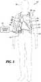
- FIG. 1illustrates a system with a patient 102 wearing an example of a WCD system 104 according to embodiments described herein.
- the WCD systemmay include a communication device 106 , a support structure 110 , an external defibrillator 118 connected to defibrillation electrodes 114 , 116 , among other components.
- the support structure 110may be worn by the patient 102 .
- the support structure 110may include a vest, shirt, series of straps, or other system enabling the patient 102 to carry at least a portion of the WCD system 104 on the patient's body.
- the support structure 110may comprise a single component.
- the support structure 110may comprise a vest or shirt that properly locates the WCD system 104 on a torso 112 of the patient 102 .
- the single component support structure 110may additionally carry or couple to the various components of the WCD system 104 .
- the support structure 110may comprise multiple components.
- the support structure 110may include a first component resting on a patient's shoulders.
- the first componentmay locate a series of defibrillation electrodes 114 , 116 on the torso 112 of the patient 102 .
- a second componentmay rest more towards the patient's hips, whereby the second component may be positioned such that the patient's hips support the heavier components of the WCD system 104 .
- the heavier components of the WCD system 104may be carried via a shoulder strap, or may be kept close to the patient 102 such as in a cart, bag, stroller, wheel chair, or other vehicle.
- the external defibrillator 118may be coupled to the support structure 110 or may be carried remotely from the patient 102 .
- the external defibrillator 118may be triggered to deliver an electric shock to the patient 102 when patient 102 wears WCD system 104 . For example, if certain thresholds are exceeded or met, the external defibrillator 118 may be engaged and deliver a shock to the patient 102 .
- the WCD system 100may defibrillate the patient 102 by delivering an electrical charge to the patient 102 through a series of electrodes 114 , 116 positioned on the torso 112 .
- the electrodes 114 , 116may be electrically coupled to the external defibrillator 118 via a series of electrode leads 120 .
- the defibrillator 118may administer an electric shock to the body of the patient 102 when the defibrillation electrodes 114 , 116 are in good electrical contact with the torso 112 of patient 102 .
- devicesproximate the electrodes 114 , 116 may emit a conductive fluid to encourage electrical contact between the patient 102 and the electrodes 114 , 116 .
- the electric shockmay be a defibrillation shock, which may go through a heart 122 of the patient 102 in an attempt to restart the heart 122 .
- the brief, strong electric pulsemay work to restart the heart 122 which may save the patient's life.
- the WCD system 104may also include either an external or internal monitoring device or some combination thereof.
- FIG. 1displays an external monitoring device 124 which may also be known as an outside monitoring device.
- the monitoring device 124may monitor at least one local parameter. Local parameters may include physical state of the patient 102 such as ECG, movement, heartrate, pulse, temperature, and the like. Local parameters may also include a parameter of the WCD 104 , environmental parameters, or the like.
- the monitoring device 124may be physically coupled to the support structure 110 or may be proximate the support structure 110 . In either location, the monitoring device 124 is communicatively coupled with other components of the WCD 104 .
- the WCD system 104may include a communication device 106 to enable the patient to interact with, and garnish data from, the WCD system 104 .
- the communication device 106may be a part of the defibrillator 118 or may be a separate device.
- the communication devices 106may include a screen 128 and one or more user inputs 130 to enable the patient to interact with the WCD system 104 .
- the patientmay view patient data, dismiss a shock if the patient is still conscious, turn off an alarm, and otherwise engage with the WCD system 104 via the communication device 106 .
- the communication device 106may be wired, or wirelessly linked to the external defibrillator 118 and may be removable from the defibrillator 118 or a separate component. In some embodiments, the communication device 106 may form an inseparable assembly and share internal components with the defibrillator 118 .
- the communication device 106 or the defibrillator 118may connect with one or more external devices 126 .
- the communication device 106 or the defibrillator 118may connect to various external devices 126 such as a cloud computing network, a remote desktop, a laptop, a mobile device, or other external device using a network such as the Internet, local area networks, wide area networks, virtual private networks (VPN), other communication networks or channels, or any combination thereof.
- VPNvirtual private networks
- FIGS. 2A and 2Billustrate an example of the defibrillator 118 with a communication device 106 according to embodiments described herein.
- the defibrillator 118may rest on along a plane 200 . However, in this position of rest, the patient may not be able to view the communication device 106 clearly. For example, the screen (e.g. screen 128 , FIG. 1 ) may be skewed or simply not in view.
- the patientmay rotate the defibrillator 118 . This may cause the defibrillator to rotate either clockwise about angle A 1 or counterclockwise about angle A 2 .
- the viewing angle of the communication device 106also changes. The change in viewing angle may cause the patient to have a difficult time viewing information. Therefore, as the defibrillator 118 rotates, the screen 128 may also rotate or align the images and text projected to correlate to either viewing angle A 1 or A 2 .
- the threshold for altering the viewing anglemay be a range of angles for angle A 1 and angle A 2 .
- the viewing anglemay rotate when angle A 1 or angle A 2 ranges from 20 degrees to 60 degrees, 30 degrees to 50 degrees, or the like.
- a rotational range for angle A 1 and angle A 2may prevent the screen from oscillating between various view orientations.
- the thresholdwas a strict degree threshold then the screen 128 may continuously alternate between viewpoints in an attempt to accommodate the shifting of the defibrillator 118 (e.g., a hysteresis-type effect). This may cause patient frustration in interacting with the device.
- some usersmay prefer a more sensitive display than others, therefore the threshold of view orientations may be personalized for the particular wearer of the WCD.
- FIG. 3is a block diagram illustrating one example of a communication device 106 .
- the communication device 106may be coupled to the defibrillator 118 or may be a separate device.
- the communication device 106has an orientation module 302 and a display module 304 .
- the patientmay view the communication device 106 at various times throughout the day in various different orientations.
- the patientmay view the communication device 106 in their dominant hand most of the time.
- the communication device 106may not always be oriented properly such that a fixed screen would naturally appear to the user. If an alarm was sounding of an impending shock, or another warning signal, the user might get flustered viewing the screen on the communication device in a disorientating or non-normal manner. For example, the user may pick up the communication device 106 upside down or in a non-dominant hand. The disorientation may cause the user to fail to deactivate the defibrillation device and as such, an unnecessary and potentially damaging shock may be delivered to the patient.
- the patientmay view the communication device 106 coupled to a defibrillation (e.g. defibrillator 118 , FIG. 1 ).
- a defibrillatione.g. defibrillator 118 , FIG. 1
- the communication device 106may be pointed away from the patient causing the patient to tilt the communication device 106 towards them. For that reason, any information displayed to the patient may be upside down or otherwise skewed. This may be true if the defibrillator 118 is coupled to the support structure or external to the support structure.
- the communication device 106may be an LCD screen which may be coupled to the defibrillator 118 in such a manner that the screen is visible on a top side of the defibrillator 118 .
- a third partymay need to interact with the WCD system but, again, the communication device 106 may not orient properly for the third party.
- a patientmay be unable to care for themselves and a nurse or family member or other individual may be providing care and may monitor the patient's health.
- a patientmay require assistance should a cardiac event or accident arise.
- the orientation module 302may help detect incorrect screen orientation or alignment.
- the orientation module 302may receive information from one or more sensors proximate the communication device 106 .
- the sensorsmay provide data readings involving the movement and orientation of the communication device 106 .
- one or more accelerometers proximate the communication device 106may determine when the device 106 is moving and the speed at which it moves.
- the accelerometermay additionally detect tilt and vibrations.
- the datamay provide feedback to determine when predetermined thresholds are met to detect movement of the device 106 .
- a gyroscopemay provide further orientation details of the device 106 .
- the orientation module 302may pull and/or receive data from these sensors, individually or collaboratively, to determine when the device 106 is in use and desired orientation features associated with that use. For example, the orientation module 302 may determine a user is picking up the communication device 106 with their left or right hand based on the sensor feedback. The orientation module 302 may further determine when the communication device 106 is flat, tilted, jilted, vibrating, or otherwise orientation. The orientation module 302 may further determine when a third party is viewing the device. The orientation module 302 may further determine if the user is interacting with the communication device 106 either on a right side or left side of their body.
- the display module 304may receive orientation information from the orientation module 302 and activate a graphical user interface (GUI) associated with the device 106 as determined. For example, the display module 304 may rotate the content of the GUI to appear upright to the patient. The display module 304 may provide visual indication such as a light, or other visual indicator to indicate a status of the communication device 106 or the WCD system (e.g. WCD system 104 , FIG. 1 ). In some embodiments, when motion is detected by the orientation module 302 , the display module 304 may activate a backlight or a screen to provide increased visibility of the content to the patient or other user. As the orientation module 302 depicts movement of the communication device 106 , the display module 304 may automatically activate at least a portion of the GUI. Activating a portion of the GUI may alert the patient to a status of the system, or other information.
- GUIgraphical user interface
- the patientmay personalize the GUI to display criteria, parameters, or other information of important to the patient.
- the display module 304may remember a preferred screen orientation.
- the display module 304may store patient preferences and remember whether the user wears the communication device 106 on either a left side or a right side of the body. The display module 304 may store this preference and automatically orient the communication device 106 to properly display to the user based on the user's preferences.
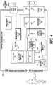
- FIG. 4is a diagram displaying various functional components of one example of a defibrillator 118 .
- the defibrillator 118may be an example of the defibrillator 118 described with reference to FIG. 1 .
- the components shown in FIG. 4may be contained within a single unit or may be separated amongst two or more units in communication with each other.
- the defibrillator 118may include a processor 402 , memory 404 , user interface 406 , defibrillation port 408 , and ECG port 410 , among other components.
- the componentsare contained within a housing 412 or casing.
- the housing 412may comprise a hard shell around the components or may comprise a softer shell for increased patient comfort.
- the processor 402 , memory 404 (including software/firmware code (SW) 414 ), user interface 406 , defibrillation port 408 , ECG port 410 , communication module 416 , measurement circuit 418 , monitoring device 420 , and energy storage module 422may communicate—directly or indirectly—with one another (e.g., via one or more buses 424 ).
- One or more buses 424may allow data communication between one or more elements and/or modules of the defibrillator 118 .
- the communication device 106may also communicate with the components of the defibrillator 118 using one or more buses 424 .
- the communication device 106may replace the user interface 406 .
- the communication device 106may share components with the defibrillator 118 including the processor 402 , memory 404 , and the like.
- the memory 404may include random access memory (RAM), read only memory (ROM), flash RAM, and/or other types.
- the memory 404may store computer-readable, computer-executable software/firmware code 414 including instructions that, when executed, cause the processor 402 to perform various functions (e.g., determine shock criteria, determine consciousness of patient, track patient parameters, etc.).
- the processor 402may include a with an intelligent hardware device, e.g., a central processing unit (CPU), a microcontroller, an application-specific integrated circuit (ASIC), etc.
- CPUcentral processing unit
- ASICapplication-specific integrated circuit
- the memory 404can contain, among other things, the Basic Input-Output system (BIOS) which may control basic hardware and/or software operations such interactions and workings of the various components of the defibrillator 118 , and in some embodiments, components external to the defibrillator 118 .
- BIOSBasic Input-Output system
- the memory 404may contain various modules to implement the workings of the defibrillator 118 and other aspects of the present disclosure.
- the defibrillator 118may include a user interface 406 .
- the user interface 406may be a part of a communication device 106 .
- the user interface 406may enable the patient to view one or metrics concerning the defibrillator 118 .
- the user interface 406may display an ECG of the patient, a status of the defibrillator 118 , a status of a charge (e.g. a battery charge or an energy storage module).
- the user interface 406may be a simple configuration and a separate device, such as an electronics module (e.g. electronics module 104 , FIG. 1 ).
- the defibrillator 118may include a defibrillation port 408 .
- the defibrillation port 408may comprise a socket, opening, or electrical connection in the housing 412 .
- the defibrillation port 408may include two or more nodes 426 , 428 .
- the two or more nodes 426 , 428may accept two or more defibrillation electrodes (e.g. defibrillation electrodes 114 , 116 , FIG. 1 ).
- the nodes 426 , 428may provide an electrical connection between the defibrillation electrodes 114 , 116 and the defibrillator 118 .
- the defibrillation electrodes 114 , 116may plug into the two or more nodes 426 , 428 via one or more leads (e.g. leads 128 ), or, in some instances, the defibrillation electrodes 114 , 116 may be hardwired to the nodes 426 , 428 . Once an electrical connection is established between the defibrillation port 408 and the electrodes 114 , 116 , the defibrillator 118 may be able to deliver an electric shock to the patient.
- the defibrillator 118may include an ECG port 410 in the housing 412 .
- the ECG port 410may accept one or more ECG electrodes 430 or ECG leads.
- the ECG electrodes 430sense a patient's ECG signal.
- the ECG electrodes 430may record electrical activity generated by the heart muscle depolarization.
- the ECG electrodes 430may utilize 4-leads to 12-leads or multichannel ECG, or the like.
- the ECG electrodes 430may connect with the patient's skin.
- the defibrillator 118may include a measurement circuit 418 .
- the measurement circuit 418may be in communication with the ECG port 410 .
- the measurement circuit 418may receive physiological signals from ECG port 410 .
- the measurement circuit 418may additionally or alternatively receive physiological signals via the defibrillation port 408 when defibrillation electrodes 114 , 116 are attached to the patient.
- the measurement circuit 418may determine a patient's ECG signal from a difference in voltage between the defibrillation electrodes 114 , 116 .
- the measurement circuit 418may monitor the electrical connection between the defibrillation electrodes 114 , 116 and the skin of the patient. For example, the measurement circuit 418 can detect impedance between electrodes 114 , 116 . The impedance may indicate the effective resistance of an electric circuit. An impedance calculation may determine when the electrodes 114 , 116 have a good electrical connection with the patient's body.
- the defibrillator 118may include an internal monitoring device 420 within the housing 412 .
- the monitoring device 420may monitor at least one local parameter.
- Local parametersmay include physical state of the patient such as ECG, movement, heartrate, pulse, temperature, and the like. Local parameters may also include a parameter of the WCD (e.g. WCD 102 ), defibrillator 118 , environmental parameters, or the like.
- a WCDmay include an internal monitoring device 420 and an external monitoring device (e.g. external monitoring device 124 ). If both monitoring devices 124 , 420 are present, the devices 124 , 420 may work together to parse out specific parameters depending on position, location, and other factors. For example, the external monitoring device 124 may monitor environmental parameters while the internal monitoring device 420 may monitor patient and system parameters.
- the defibrillator 118may include a power source 432 .
- the power source 432may comprise a battery or battery pack, which may be rechargeable.
- the power source 432may comprise a series of different batteries to ensure the defibrillator 118 has power.
- the power source 432may include a series of rechargeable batteries as a prime power source and a series of non-rechargeable batteries as a secondary source. If the patient is proximate an AC power source, such as when sitting down, sleeping, or the like, the power source 432 may include an AC override wherein the power source 432 draws power from the AC source.
- the defibrillator 118may include an energy storage module 422 .
- the energy storage module 422may store electrical energy in preparation or anticipation of providing a sudden discharge of electrical energy to the patient.
- the energy storage module 422may have its own power source and/or battery pack.
- the energy storage module 422may pull power from the power source 432 .
- the energy storage module 422may include one or more capacitors 434 .
- the one or more capacitors 434may store an electrical charge, which may be administered to the patient.
- the processor 402may be communicatively coupled to the energy storage module 422 to trigger the amount and timing of electrical energy to provide to the defibrillation port 408 and, subsequently, the patient.
- the defibrillator 118may include a discharge circuit 436 .
- the discharge circuit 436may control the energy stored in the energy storage module 422 .
- the discharge circuit 436may either electrical couple or decouple the energy storage module 422 to the defibrillation port 408 .
- the discharge circuit 436may be communicatively coupled to the processor 402 to control when the energy storage module 422 and the defibrillation port 408 should or should not be coupled to either administer or prevent a charge from emitting from the defibrillator 118 .
- the discharge circuit 436may include on or more switches 438 .
- the one or more switches 438may include an H-bridge.
- the defibrillator 118may include a communication module 416 .
- the communication module 416may establish one or more communication links with either local hardware and/or software to the WCD and defibrillator 118 or to remote hardwire separate from the WCD system.
- the communication module 416may include one or more antennas, processors, and the like.
- the communication module 416may communicate wirelessly via radio frequency, electromagnetics, local area networks (LAN), wide area networks (WAN), virtual private networks (VPN), RFID, Bluetooth, cellular networks, and the like.
- the communication module 416may facilitate communication of data and commands such as patient data, episode information, therapy attempted, CPR performance, system data, environmental data, and so on.
- the processor 402may execute one or more modules.
- the processor 402may execute a detection module 440 and/or an action module 442 .
- the detection module 440may be a logic device or algorithm to determine if any or a variety thresholds are exceeded which may require action of the defibrillator 118 .
- the detection module 440may receive and interpret all of the signals from the ECG port 410 , the defibrillation port 408 , the monitoring device 420 , an external monitoring device, and the like.
- the detection module 440may process the information to ensure the patient is still conscious and healthy. If any parameter indicates the patient may be experiencing distress or indicating a cardiac episode, the detection module 440 may activate the action module 442 .
- the action module 442may receive data from the detection module 440 and perform a series of actions. For example, an episode may merely be a loss of batter power at the power source 432 or the energy storage module 422 , or one or more electrodes (e.g., ECG electrodes, defibrillation electrodes) may have lost connection. In such instances, the action module 442 may trigger an alert to the patient or to an outside source of the present situation. If an episode is a health risk, such as a cardiac event, the action module 442 may begin a series of steps.
- an episodemay merely be a loss of batter power at the power source 432 or the energy storage module 422 , or one or more electrodes (e.g., ECG electrodes, defibrillation electrodes) may have lost connection. In such instances, the action module 442 may trigger an alert to the patient or to an outside source of the present situation. If an episode is a health risk, such as a cardiac event, the action module 442 may begin a series of steps.
- Thismay include issuing a warning to the patient, issuing a warning to a third party, priming the energy storage module 422 for defibrillation, releasing one or more conductive fluids proximate defibrillation electrodes 114 , 116 , and the like.
- FIG. 5is a diagram displaying various functional components of an example communication device 106 for use with a WCD system 104 .
- the communication device 106may be an example of the communication device 106 described with reference to FIG. 1 .
- the communication device 106may be a part of the defibrillator 118 or may be a separate device communicatively coupled to the defibrillator 118 .
- the components shown in FIG. 5may be contained within a single unit or may be separated amongst two or more units in communication with each other.
- the communication device 106may include a controller 502 , memory 504 , I/O controller 506 , user interface 508 , and the like.
- the componentsare contained within a housing 500 or casing.
- the housing 500may be integrated into the defibrillator 118 .
- the communication device 106may share components or functionality with the defibrillator 118 .
- the communication device 106may use the processor 402 and memory 404 and other such components.
- the communication device 106may be movable in relation to the defibrillator 118 .
- the communication device 106may be linked or movably coupled to the defibrillator 118 about a pivot joint or the like.
- the communication device 106may be removable from the defibrillator 118 .
- the communication device 106may be a separate device.
- the controller 502 , memory, 504 (including software/firmware code (SW) 512 ), input/output controller module 506 , user interface module 508 , transceiver module 514 , and one or more antennas 516may communicate—directly or indirectly—with one another (e.g., via one or more buses 520 ).
- the transceiver module 514may communicate bi-directionally—via the one or more antennas 516 , wired links, and/or wireless links—with the defibrillator 118 or remote devices 126 as described previously.
- the transceiver module 514may include a modem which may modulate packets and provide the modulated packets to the one or more antennas 516 for transmission, and to demodulate packets received from the one or more antenna 516 . While a single antenna 516 is shown, the communication device may include several antennas 516 which may concurrently transmit and/or receive multiple wired and/or wireless transmissions. In some embodiments, the communication device 106 may provide a connection using wireless techniques, including digital cellular connection, Cellular Digital Packet Data (CDPD) connection, digital satellite data connection, and/or another connection.
- CDPDCellular Digital Packet Data
- the controller 502may control one or more operations of the communication device 106 .
- the controller 502may include of one or more processors, implemented as a Central Processing Unit (CPU), a digital signal processor, a microprocessor, a microcontroller, an application-specific integrated circuit (ASIC), a programmable logic device (PLD), or other implementation.
- the controller 502may include a single chip combined with memory controller and a peripherals interface.
- the memory 504may be a non-transitory computer-readable storage medium. In some embodiments, the memory 504 may include both persistent/non-volatile and non-persistent/volatile memory components.
- the memory 504may include volatile memory, non-volatile memory (NVM), for example RAM, ROM, EEPROM, flash memory, or some combination thereof.
- NVMnon-volatile memory
- the memory 504may store computer-readable, computer executable software/firmware code 512 that, when executed, may cause the controller 502 to perform various functions as described herein.
- the memory 504can contain, among other things, the Basic Input-Output system (BIOS) which may control basic hardware and/or software operations such interactions and workings of the various components of the communication device 106 , and in some embodiments, components external to the communication device.
- BIOSBasic Input-Output system
- the memory 504may contain various modules to implement the workings of the communication device 106 and other aspects of the present disclosure.
- the communication device 106may include one or more sensors 518 .
- the one or more sensor 518may include orientation sensors, accelerometers, motion sensors, gyroscope, ambient light sensors, touchscreen sensors, magnetometer, sound sensors, or some combination thereof.
- An orientation sensormay measure the orientation of the communication device 106 relative to an orthogonal coordinate frame.
- An accelerometermay detect acceleration, vibration, and tilt to determine movement and exact orientation along the orthogonal coordinate frame.
- a gyroscopemay provide further and/or additional orientation details and direction like up/down and left/right.
- the one or more sensors 518may work in conjunction with the orientation module 302 and display module 304 to properly orient and wake a screen for the patient to interact with the communication device 106 .
- the user interface 508may coordinate communication with the patient.
- the user interface 508may receive inputs from the user and also may generate outputs to the user.
- the outputscan be visual, sound, vibrations, lights, images, and so on.
- the user interfacemay include one or more individual devices such as a screen 128 , touch-screen, a keypad 130 , an optical finger interface, one or more speakers, one or more microphones, one or more accelerometers, one or more buttons, and so on.
- the communication device 106may also include components for bi-directional voice and data communications including components for transmitting communications and components for receiving communications.
- the communication device 106may communicate bi-directionally with the defibrillator 118 , the WCD system 104 , and/or external devices 124 .
- the bi-directional communicationmay be direct or indirect.
- the orientation module 302may receive information from the one or more sensors 518 to determine movement or other inputs on the user interface 508 . For example, the orientation module 302 may detect when there is a lack of movement and, as such, may put the user interface 508 into a sleep mode. The sleep mode may help preserve the battery life of the communication device 106 , or if the communication device is a part of the defibrillator (e.g. defibrillator 118 ) preserve the battery of the defibrillator. The orientation module 302 may additionally detect when sudden movements or slower movements have occurred indicating the patient or a third party is interacting with the communication device 106 .
- the orientation module 302may additionally detect when sudden movements or slower movements have occurred indicating the patient or a third party is interacting with the communication device 106 .
- the orientation module 302may work in conjunction with a display module 304 .
- the display module 304may affect the changes requires in the visual interface between the patient and the user interface 508 .
- the display module 304may rotate the visual display such that the display maintains an upright orientation to the user. This may include rotation about any pivot axis.
- the communication device 106may include a power source 520 .
- the power source 520may comprise a battery or battery pack, which may be rechargeable.
- the power source 520may comprise a series of different batteries to ensure the communication device 106 has power.
- the power source 520may include a series of rechargeable batteries as a prime power source and a series of non-rechargeable batteries as a secondary source. If the patient is proximate an AC power source, such as when sitting down, sleeping, or the like, the power source 520 may include an AC override wherein the power source 520 draws power from the AC source.
- FIG. 6is a flow chart illustrating an example of a method 600 for WCD systems, in accordance with various aspects of the present disclosure. For clarity, the method 600 is described below with reference to aspects of one or more of the systems described herein.
- a separate communication devicemay perform one or more of the functions described below.
- a communication device coupled to the defibrillator or the WCD systemmay perform one or more of the functions described below.
- the method 600may include detecting a motion at a graphical user interface.
- the motionmay be proximate a communication device or proximate a visual display coupled to the defibrillator unit.
- the motionmay be a lateral motion, fixed-axis rotation, or may be a gyroscopic motion.
- the motionmay be continuous and linear, or it may be sudden and uncontrolled, or it may be some combination of those.
- the method 600may include determining an orientation of the graphical user interface based at least in part on the detection of a motion at the graphical user interface. For example, the method 600 may determine if a set threshold or threshold range has been satisfied or exceeded. The method 600 may compare the detected motion to specific user requirements on GUI orientation, or may compare the detected motion to general use profiles. In some embodiments, the method 600 may determine an action to take based on the type of motion. For example, the method 600 may determine if the user interface needs to be activated or turned on, if the user interface needs to be properly oriented, or if the user is interacting with the device using either their left hand or their right hand and a correlating user interface orientation. The method 600 may determine if the user interface needs to activate, be rotated, or if the user is interacting with the device with a specific hand, or the like.
- the methodmay include orienting a display of the GUI. For example, once motion is detected and determined, the method may proceed to properly orient the GUI or screen such that the patient or third party is properly viewing the screen in a better orientation.
- the method 600may provide for the communication device reacting to one or more movements or user inputs. It should be noted that the method 600 is just one implementation and that the operations of the method 800 may be rearranged or otherwise modified such that other implementations are possible.
- FIG. 7is a flow chart illustrating an example of a method 700 for WCD systems, in accordance with various aspects of the present disclosure. For clarity, the method 700 is described below with reference to aspects of one or more of the systems described herein.
- a separate communication devicemay perform one or more of the functions described below.
- a communication device coupled to the defibrillator or the WCD systemmay perform one or more of the functions described below.
- the method 700may include detecting a motion at a graphical user interface.
- the method 700may include determining if the motion is user-activated.
- the motionmay be a result of exercise, bodily movement, or other external actions or activities.
- Such motionmay be continuous and linear or rhythmic, for example. If a patient accidently bumps the communication device, the sensors may detect motion but the motion may not be purposely induced. Such motion may be sudden and discontinuous, for example. Therefore, the method 700 may ascertain differences in movements between purposeful and environmental or accidental.
- the method 700may include determining an axis of rotation and a directional vector. For example, if a user is purposefully interacting with the communication device, the method 700 may determine which axis the communication device is pivoting about and in which direction. The method 700 , using this information, may then, at block 604 , determine an orientation of the GUI and, at block 606 , orient a display of the GUI.
- the method 700may provide for communication device reacting to one or more movements or user inputs. It should be noted that the method 700 is just one implementation and that the operations of the method 700 may be rearranged or otherwise modified such that other implementations are possible.
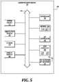
- FIG. 8is a flow chart illustrating an example of a method 800 for WCD systems, in accordance with various aspects of the present disclosure. For clarity, the method 800 is described below with reference to aspects of one or more of the systems described herein.
- a separate communication devicemay perform one or more of the functions described below.
- a communication device coupled to the defibrillator or the WCD systemmay perform one or more of the functions described below.
- the methodmay include detecting a motion at a graphical user interface.
- the method 800may include determining if the motion is user-activated.
- the method 800may include illuminating a visual status indicator.
- the usermay have engaged the communication device to check a status of the WCD system. Therefore, the method 800 may provide visual feedback to the user of a status of the system. This may include illuminating various lights, such as LED lights, in different colors or in different orientations to display a status of the WCD system.
- the status indicatorsmay include a status of a battery life, electrode connectivity, heart rate, and the like. The visual indicator may quickly indicate to the patient whether the WCD system is properly functioning without having to view a screen or further engage or interact with the WCD system.
- the method 800may provide for communication device reacting to one or more movements or user inputs. It should be noted that the method 800 is just one implementation and that the operations of the method 800 may be rearranged or otherwise modified such that other implementations are possible.
- This documentmay include references to directions, such as “forward,” “rearward,” “front,” “rear,” “upward,” “downward,” “top,” “bottom,” “right hand,” “left hand,” “lateral,” “medial,” “in,” “out,” “extended,” etc. These references, and other similar references, are only to assist in helping describe and to understand the particular embodiments and are not intended to limit the present disclosure to these directions or locations.
- the present documentmay also reference quantities and numbers. Unless specifically stated, such quantities and numbers are not to be considered restrictive, but exemplary of the possible quantities or numbers associated with the present application. Also in this regard, the present application may use the term “plurality” to reference a quantity or number. The terms “about,” “approximately,” “near,” etc., mean plus or minus 5% of the stated value.
Landscapes
- Health & Medical Sciences (AREA)
- Engineering & Computer Science (AREA)
- Cardiology (AREA)
- Radiology & Medical Imaging (AREA)
- Biomedical Technology (AREA)
- Nuclear Medicine, Radiotherapy & Molecular Imaging (AREA)
- Life Sciences & Earth Sciences (AREA)
- Animal Behavior & Ethology (AREA)
- General Health & Medical Sciences (AREA)
- Public Health (AREA)
- Veterinary Medicine (AREA)
- Heart & Thoracic Surgery (AREA)
- Human Computer Interaction (AREA)
- Electrotherapy Devices (AREA)
Abstract
Description
Claims (20)
Priority Applications (2)
| Application Number | Priority Date | Filing Date | Title |
|---|---|---|---|
| US16/394,565US11298556B2 (en) | 2018-04-25 | 2019-04-25 | WCD user interface response to a change in device orientation |
| US17/717,322US12115378B2 (en) | 2018-04-25 | 2022-04-11 | WCD user interface response to a change in device orientation |
Applications Claiming Priority (2)
| Application Number | Priority Date | Filing Date | Title |
|---|---|---|---|
| US201862662472P | 2018-04-25 | 2018-04-25 | |
| US16/394,565US11298556B2 (en) | 2018-04-25 | 2019-04-25 | WCD user interface response to a change in device orientation |
Related Child Applications (1)
| Application Number | Title | Priority Date | Filing Date |
|---|---|---|---|
| US17/717,322ContinuationUS12115378B2 (en) | 2018-04-25 | 2022-04-11 | WCD user interface response to a change in device orientation |
Publications (2)
| Publication Number | Publication Date |
|---|---|
| US20190329053A1 US20190329053A1 (en) | 2019-10-31 |
| US11298556B2true US11298556B2 (en) | 2022-04-12 |
Family
ID=68291974
Family Applications (2)
| Application Number | Title | Priority Date | Filing Date |
|---|---|---|---|
| US16/394,565Active2039-08-09US11298556B2 (en) | 2018-04-25 | 2019-04-25 | WCD user interface response to a change in device orientation |
| US17/717,322ActiveUS12115378B2 (en) | 2018-04-25 | 2022-04-11 | WCD user interface response to a change in device orientation |
Family Applications After (1)
| Application Number | Title | Priority Date | Filing Date |
|---|---|---|---|
| US17/717,322ActiveUS12115378B2 (en) | 2018-04-25 | 2022-04-11 | WCD user interface response to a change in device orientation |
Country Status (1)
| Country | Link |
|---|---|
| US (2) | US11298556B2 (en) |
Families Citing this family (1)
| Publication number | Priority date | Publication date | Assignee | Title |
|---|---|---|---|---|
| US11806544B2 (en)* | 2020-12-22 | 2023-11-07 | Stryker Corporation | Medical device with modifiable view of an electrocardiogram |
Citations (68)
| Publication number | Priority date | Publication date | Assignee | Title |
|---|---|---|---|---|
| US3724355A (en) | 1970-06-12 | 1973-04-03 | K Schranz | Apparatus for processing exposed photographic film or the like |
| US4583524A (en) | 1984-11-21 | 1986-04-22 | Hutchins Donald C | Cardiopulmonary resuscitation prompting |
| US4619265A (en) | 1984-03-08 | 1986-10-28 | Physio-Control Corporation | Interactive portable defibrillator including ECG detection circuit |
| US4928690A (en) | 1988-04-25 | 1990-05-29 | Lifecor, Inc. | Portable device for sensing cardiac function and automatically delivering electrical therapy |
| US4955381A (en) | 1988-08-26 | 1990-09-11 | Cardiotronics, Inc. | Multi-pad, multi-function electrode |
| US5078134A (en) | 1988-04-25 | 1992-01-07 | Lifecor, Inc. | Portable device for sensing cardiac function and automatically delivering electrical therapy |
| US5228449A (en) | 1991-01-22 | 1993-07-20 | Athanasios G. Christ | System and method for detecting out-of-hospital cardiac emergencies and summoning emergency assistance |
| US5353793A (en) | 1991-11-25 | 1994-10-11 | Oishi-Kogyo Company | Sensor apparatus |
| US5394892A (en) | 1990-04-02 | 1995-03-07 | K J Mellet Nominees Pty Ltd | CPR prompting apparatus |
| US5405362A (en) | 1991-04-29 | 1995-04-11 | The Board Of Regents For The University Of Texas System | Interactive external defibrillation and drug injection system |
| US5474574A (en) | 1992-06-24 | 1995-12-12 | Cardiac Science, Inc. | Automatic external cardioverter/defibrillator |
| US5662690A (en) | 1994-12-08 | 1997-09-02 | Heartstream, Inc. | Defibrillator with training features and pause actuator |
| US5782878A (en) | 1994-12-07 | 1998-07-21 | Heartstream, Inc. | External defibrillator with communications network link |
| US5792204A (en) | 1996-05-08 | 1998-08-11 | Pacesetter, Inc. | Methods and apparatus for controlling an implantable device programmer using voice commands |
| WO1998039061A2 (en) | 1997-03-07 | 1998-09-11 | Cadent Medical Corporation | Wearable defibrillation system |
| US5902249A (en) | 1995-03-03 | 1999-05-11 | Heartstream, Inc. | Method and apparatus for detecting artifacts using common-mode signals in differential signal detectors |
| US5913685A (en) | 1996-06-24 | 1999-06-22 | Hutchins; Donald C. | CPR computer aiding |
| US6047203A (en) | 1997-03-17 | 2000-04-04 | Nims, Inc. | Physiologic signs feedback system |
| US6065154A (en) | 1998-04-07 | 2000-05-23 | Lifecor, Inc. | Support garments for patient-worn energy delivery apparatus |
| US6108197A (en) | 1992-05-15 | 2000-08-22 | Via, Inc. | Flexible wearable computer |
| US6201992B1 (en) | 1999-04-01 | 2001-03-13 | Agilent Technologies, Inc. | Defibrillator interface capable of generating video images |
| US6263238B1 (en) | 1998-04-16 | 2001-07-17 | Survivalink Corporation | Automatic external defibrillator having a ventricular fibrillation detector |
| US6287328B1 (en) | 1999-04-08 | 2001-09-11 | Agilent Technologies, Inc. | Multivariable artifact assessment |
| US6319011B1 (en) | 1995-04-06 | 2001-11-20 | Michael J. Motti | Automatic training defibrillator simulator and method |
| US6334070B1 (en) | 1998-11-20 | 2001-12-25 | Medtronic Physio-Control Manufacturing Corp. | Visual and aural user interface for an automated external defibrillator |
| US6356785B1 (en) | 1997-11-06 | 2002-03-12 | Cecily Anne Snyder | External defibrillator with CPR prompts and ACLS prompts and methods of use |
| US6437083B1 (en) | 2001-12-06 | 2002-08-20 | General Electric Company | Process for preparing branched aromatic polycarbonates |
| US6529875B1 (en) | 1996-07-11 | 2003-03-04 | Sega Enterprises Ltd. | Voice recognizer, voice recognizing method and game machine using them |
| US20030158593A1 (en) | 2002-02-19 | 2003-08-21 | Heilman Marlin S. | Cardiac garment |
| US6681003B2 (en) | 1999-10-05 | 2004-01-20 | Lifecor, Inc. | Data collection and system management for patient-worn medical devices |
| US6762917B1 (en) | 2001-06-12 | 2004-07-13 | Novx Corporation | Method of monitoring ESC levels and protective devices utilizing the method |
| US20050107833A1 (en) | 2003-11-13 | 2005-05-19 | Freeman Gary A. | Multi-path transthoracic defibrillation and cardioversion |
| US7065401B2 (en) | 2002-05-08 | 2006-06-20 | Michael Worden | Method of applying electrical signals to a patient and automatic wearable external defibrillator |
| US20060173499A1 (en) | 2005-01-31 | 2006-08-03 | Medtronic Emergency Response Systems, Inc. | System and method for using diagnostic pulses in connection with defibrillation therapy |
| US20080312709A1 (en)* | 2007-06-13 | 2008-12-18 | Volpe Shane S | Wearable medical treatment device with motion/position detection |
| US20090005827A1 (en) | 2007-06-26 | 2009-01-01 | David Weintraub | Wearable defibrillator |
| US7559902B2 (en) | 2003-08-22 | 2009-07-14 | Foster-Miller, Inc. | Physiological monitoring garment |
| US20100007413A1 (en) | 2006-11-10 | 2010-01-14 | Koninklijke Philips Electronics N.V. | Ecg electrode contact quality measurement system |
| US20100298899A1 (en) | 2007-06-13 | 2010-11-25 | Donnelly Edward J | Wearable medical treatment device |
| US7865238B2 (en) | 2004-09-29 | 2011-01-04 | Koninklijke Philips Electronics N.V. | High-voltage module for an external defibrillator |
| US7870761B2 (en) | 2002-05-14 | 2011-01-18 | Koninklijke Philips Electronics N.V. | Garment and method for producing the same |
| US20110288605A1 (en) | 2010-05-18 | 2011-11-24 | Zoll Medical Corporation | Wearable ambulatory medical device with multiple sensing electrodes |
| US20110288604A1 (en) | 2010-05-18 | 2011-11-24 | Kaib Thomas E | Wearable therapeutic device |
| US20120001943A1 (en)* | 2010-07-02 | 2012-01-05 | Fujitsu Limited | Electronic device, computer-readable medium storing control program, and control method |
| US20120112903A1 (en) | 2010-11-08 | 2012-05-10 | Zoll Medical Corporation | Remote medical device alarm |
| US20120144551A1 (en) | 2010-12-09 | 2012-06-14 | Eric Guldalian | Conductive Garment |
| US20120150008A1 (en) | 2010-12-09 | 2012-06-14 | Kaib Thomas E | Electrode with redundant impedance reduction |
| US20120158075A1 (en) | 2010-12-16 | 2012-06-21 | Kaib Thomas E | Water resistant wearable medical device |
| US20120265265A1 (en) | 2011-04-13 | 2012-10-18 | Mehdi Razavi | Automated External Defibrillator Pad System |
| US20120283794A1 (en) | 2011-05-02 | 2012-11-08 | Kaib Thomas E | Patient-worn energy delivery apparatus and techniques for sizing same |
| US20120302860A1 (en) | 2011-03-25 | 2012-11-29 | Zoll Medical Corporation | Selection of optimal channel for rate determination |
| US8369944B2 (en) | 2007-06-06 | 2013-02-05 | Zoll Medical Corporation | Wearable defibrillator with audio input/output |
| US20130085538A1 (en) | 2011-09-01 | 2013-04-04 | Zoll Medical Corporation | Wearable monitoring and treatment device |
| US20130231711A1 (en) | 2012-03-02 | 2013-09-05 | Thomas E. Kaib | Systems and methods for configuring a wearable medical monitoring and/or treatment device |
| US20130245388A1 (en) | 2011-09-01 | 2013-09-19 | Mc10, Inc. | Electronics for detection of a condition of tissue |
| US20130274565A1 (en) | 2012-04-13 | 2013-10-17 | Alois Antonin Langer | Outpatient health emergency warning system |
| US20130325078A1 (en) | 2012-05-31 | 2013-12-05 | Zoll Medical Corporation | Medical monitoring and treatment device with external pacing |
| US20140012144A1 (en) | 2012-07-09 | 2014-01-09 | William E. Crone | Perfusion detection system |
| US20140025131A1 (en) | 2012-07-20 | 2014-01-23 | Physio-Control, Inc. | Wearable defibrillator with voice prompts and voice recognition |
| US20140046391A1 (en) | 2012-08-10 | 2014-02-13 | Physio-Control, Inc. | Wearable defibrillator system communicating via mobile communication device |
| US20140070957A1 (en) | 2012-09-11 | 2014-03-13 | Gianluigi LONGINOTTI-BUITONI | Wearable communication platform |
| US20140245161A1 (en)* | 2010-09-30 | 2014-08-28 | Fitbit, Inc. | Motion-Activated Display of Messages on an Activity Monitoring Device |
| US20140378812A1 (en) | 2011-12-20 | 2014-12-25 | Sensible Medical Innovatons | Thoracic garment of positioning electromagnetic (em) transducers and methods of using such thoracic garment |
| US20150039053A1 (en) | 2013-06-28 | 2015-02-05 | Zoll Medical Corporation | Systems and methods of delivering therapy using an ambulatory medical device |
| US9132267B2 (en) | 2013-03-04 | 2015-09-15 | Zoll Medical Corporation | Flexible therapy electrode system |
| US20150331996A1 (en)* | 2014-05-13 | 2015-11-19 | West Affum Holdings Corp. | Network-accessible data about patient with wearable cardiac defibrillator system |
| US20160004831A1 (en) | 2014-07-07 | 2016-01-07 | Zoll Medical Corporation | Medical device with natural language processor |
| US9721375B1 (en)* | 2013-07-25 | 2017-08-01 | Duelight Llc | Systems and methods for displaying representative images |
Family Cites Families (69)
| Publication number | Priority date | Publication date | Assignee | Title |
|---|---|---|---|---|
| US4666432A (en) | 1985-09-13 | 1987-05-19 | Mcneish Kenneth | Catheter retaining means and method |
| US4698848A (en) | 1986-09-26 | 1987-10-13 | Buckley Mary C | Blouse for cardiac patients |
| US5429593A (en) | 1993-12-23 | 1995-07-04 | Matory; Yvedt L. | Post-surgical, drainage accommodating, compression dressing |
| US5618208A (en) | 1994-06-03 | 1997-04-08 | Siemens Medical Systems, Inc. | Fully insulated, fully shielded electrical connector arrangement |
| US5708978A (en) | 1994-08-17 | 1998-01-20 | Johnsrud; Anna C. | Medical vest |
| US5674249A (en)* | 1996-05-02 | 1997-10-07 | Incontrol, Inc. | Atrial defibrillation system having a portable communication device |
| US6280461B1 (en) | 1996-05-23 | 2001-08-28 | Lifecor, Inc. | Patient-worn energy delivery apparatus |
| US5741306A (en) | 1996-05-23 | 1998-04-21 | Lifecor, Inc. | Patient-worn energy delivery apparatus |
| US5944669A (en) | 1997-11-20 | 1999-08-31 | Lifecor, Inc. | Apparatus and method for sensing cardiac function |
| US6450942B1 (en) | 1999-08-20 | 2002-09-17 | Cardiorest International Ltd. | Method for reducing heart loads in mammals |
| US20040116969A1 (en) | 2002-08-26 | 2004-06-17 | Owen James M. | Pulse detection using patient physiological signals |
| US8972017B2 (en) | 2005-11-16 | 2015-03-03 | Bioness Neuromodulation Ltd. | Gait modulation system and method |
| US7653431B2 (en) | 2005-12-20 | 2010-01-26 | Cardiac Pacemakers, Inc. | Arrhythmia discrimination based on determination of rate dependency |
| US7738965B2 (en) | 2006-04-28 | 2010-06-15 | Medtronic, Inc. | Holster for charging pectorally implanted medical devices |
| US8527028B2 (en) | 2007-05-16 | 2013-09-03 | Medicomp, Inc. | Harness with sensors |
| US8560044B2 (en) | 2007-05-16 | 2013-10-15 | Medicomp, Inc. | Garment accessory with electrocardiogram sensors |
| EP2194858B1 (en) | 2007-09-14 | 2017-11-22 | Corventis, Inc. | Medical device automatic start-up upon contact to patient tissue |
| US8116841B2 (en) | 2007-09-14 | 2012-02-14 | Corventis, Inc. | Adherent device with multiple physiological sensors |
| WO2009036316A1 (en) | 2007-09-14 | 2009-03-19 | Corventis, Inc. | Energy management, tracking and security for adherent patient monitor |
| EP3922171A1 (en) | 2007-09-14 | 2021-12-15 | Medtronic Monitoring, Inc. | Adherent cardiac monitor with advanced sensing capabilities |
| US8626297B2 (en) | 2007-09-20 | 2014-01-07 | Boston Scientific Neuromodulation Corporation | Apparatus and methods for charging an implanted medical device power source |
| US7753759B2 (en) | 2007-10-22 | 2010-07-13 | Tammy Pintor | Article of apparel for concealing objects |
| EP2446926B1 (en) | 2008-05-07 | 2013-06-26 | Cameron Health, Inc. | Devices for accurately classifying cardiac activity |
| JP5559810B2 (en) | 2008-12-15 | 2014-07-23 | コーヴェンティス,インク. | Patient monitoring system and method |
| US8615295B2 (en) | 2009-03-17 | 2013-12-24 | Cardiothrive, Inc. | External defibrillator |
| US8781576B2 (en) | 2009-03-17 | 2014-07-15 | Cardiothrive, Inc. | Device and method for reducing patient transthoracic impedance for the purpose of delivering a therapeutic current |
| US8904214B2 (en) | 2010-07-09 | 2014-12-02 | Zoll Medical Corporation | System and method for conserving power in a medical device |
| US8548557B2 (en) | 2010-08-12 | 2013-10-01 | Covidien Lp | Medical electrodes |
| JP5988991B2 (en) | 2010-12-10 | 2016-09-07 | ゾール メディカル コーポレイションZOLL Medical Corporation | Wearable treatment device |
| US20120191476A1 (en) | 2011-01-20 | 2012-07-26 | Reid C Shane | Systems and methods for collection, organization and display of ems information |
| US9135398B2 (en) | 2011-03-25 | 2015-09-15 | Zoll Medical Corporation | System and method for adapting alarms in a wearable medical device |
| EP2702621B1 (en) | 2011-04-28 | 2016-06-22 | Zoll Circulation, Inc. | Latch mechanism for battery retention |
| BR112013032419A2 (en) | 2011-06-20 | 2017-01-17 | Healthwatch Ltd | Independent, non-interfering usable health monitoring and alert system |
| US8742349B2 (en) | 2011-09-21 | 2014-06-03 | Carestream Health, Inc. | Portable radiographic detector exterior battery latch and methods for using the same |
| US20130317852A1 (en) | 2012-05-22 | 2013-11-28 | Geneva Healthcare, LLC | Medical device information portal |
| JP6407881B2 (en) | 2012-11-24 | 2018-10-17 | ヘルスウォッチ・リミテッドHealthwatch Ltd. | Float loop type fabric electrode and knitting method thereof |
| US9320884B2 (en) | 2012-12-11 | 2016-04-26 | Nexus Control Systems, Llc | Method and system for switching shock vectors and decreasing transthoracic impedance for cardioversion and defibrillation |
| US9345898B2 (en) | 2013-01-23 | 2016-05-24 | West Affum Holdings Corp. | Wearable cardiac defibrillator system controlling conductive fluid deployment |
| CN105007769B (en) | 2013-02-13 | 2017-03-08 | 健康监测有限公司 | Method for limiting the elasticity of selection area in knitted fabric |
| US9757579B2 (en) | 2013-02-25 | 2017-09-12 | West Affum Holdings Corp. | Wearable cardioverter defibrillator (WCD) system informing patient that it is validating just-detected cardiac arrhythmia |
| US9089685B2 (en) | 2013-02-25 | 2015-07-28 | West Affum Holdings Corp. | Wearable defibrillator with a multivector shock waveform |
| US20150328472A1 (en) | 2014-05-13 | 2015-11-19 | Physio-Control, Inc. | Wearable cardioverter defibrillator components discarding ecg signals prior to making shock/no shock determination |
| US9592403B2 (en) | 2013-02-25 | 2017-03-14 | West Affum Holdings Corp. | Wearable cardioverter defibrillator (WCD) system making shock/no shock determinations from multiple patient parameters |
| US10500403B2 (en) | 2013-02-25 | 2019-12-10 | West Affum Holdings Corp. | WCD system validating detected cardiac arrhythmias thoroughly so as to not sound loudly due to some quickly self-terminating cardiac arrhythmias |
| US10016613B2 (en) | 2013-04-02 | 2018-07-10 | West Affum Holdings Corp. | Wearable cardiac defibrillator system long-term monitoring alternating patient parameters other than ECG |
| US20160113581A1 (en) | 2013-06-07 | 2016-04-28 | Healthwatch Ltd. | Docking station for smart garments |
| US10279189B2 (en) | 2013-06-14 | 2019-05-07 | Cardiothrive, Inc. | Wearable multiphasic cardioverter defibrillator system and method |
| US9955938B2 (en) | 2013-06-26 | 2018-05-01 | Zoll Medical Corporation | Therapeutic device including acoustic sensor |
| IN2015DN02541A (en) | 2013-10-18 | 2015-09-11 | Healthwatch Ltd | |
| US10188159B2 (en) | 2013-10-25 | 2019-01-29 | Armour Technologies, Inc. | Apparatus, system, and method for reducing head or neck trauma |
| AU2014362378A1 (en) | 2013-12-11 | 2016-06-23 | Uber Technologies, Inc. | Optimizing selection of drivers for transport requests |
| SG11201607189VA (en) | 2014-03-09 | 2016-09-29 | Healthwatch Ltd | Elastic conductive stripe and methods of utilizing thereof |
| RU2016144983A (en) | 2014-04-17 | 2018-05-16 | Хелсуотч Лтд. | DEVICES AND METHODS FOR OBTAINING WORKING ECG SIGNALS BY USING DRY KNITTED ELECTRODES |
| KR101968941B1 (en) | 2014-04-18 | 2019-04-15 | 헬스와치 리미티드 | Connector and cable assembly for smart garments |
| US20180116537A1 (en) | 2014-07-07 | 2018-05-03 | Zoll Medical Corporation | System and Method for Distinguishing a Cardiac Event From Noise in an Electrocardiogram (ECG) Signal |
| US20160076175A1 (en) | 2014-09-11 | 2016-03-17 | Myant Capital Partners Inc. | Compression fabrics with tailored comfort |
| CA2904754C (en) | 2014-09-17 | 2023-01-24 | Myant Capitals Partners Inc. | Seamless silhouette with engineered insulation property |
| CN107106857B (en) | 2014-12-18 | 2021-06-08 | 皇家飞利浦有限公司 | Wearable Cardioverter Defibrillator (WCD) apparatus and method for improved comfort and longer wearing |
| US9886680B2 (en) | 2015-03-24 | 2018-02-06 | Zoll Medical Corporation | Low-power signaling for medical devices and medical device personnel |
| US9901741B2 (en) | 2015-05-11 | 2018-02-27 | Physio-Control, Inc. | Wearable cardioverter defibrillator (WCD) system using sensor modules with reassurance code for confirmation before shock |
| US10535278B2 (en) | 2015-08-05 | 2020-01-14 | Myant, Inc. | Garment with stretch sensors |
| US20170243327A1 (en)* | 2016-02-19 | 2017-08-24 | Lenovo (Singapore) Pte. Ltd. | Determining whether to rotate content based on identification of angular velocity and/or acceleration of device |
| US10325442B2 (en) | 2016-10-12 | 2019-06-18 | Uber Technologies, Inc. | Facilitating direct rider driver pairing for mass egress areas |
| US11052241B2 (en) | 2016-11-03 | 2021-07-06 | West Affum Holdings Corp. | Wearable cardioverter defibrillator (WCD) system measuring patient's respiration |
| US11083906B2 (en) | 2017-01-05 | 2021-08-10 | West Affum Holdings Corp. | Wearable cardioverter defibrillator having adjustable alarm time |
| US11154230B2 (en) | 2017-01-05 | 2021-10-26 | West Affum Holdings Corp. | Wearable cardioverter defibrillator having reduced noise prompts |
| US11213691B2 (en) | 2017-02-27 | 2022-01-04 | Zoll Medical Corporation | Ambulatory medical device interaction |
| US10918879B2 (en) | 2017-07-28 | 2021-02-16 | West Affum Holdings Corp. | Wearable cardioverter defibrillator (WCD) system reacting to high-amplitude ECG noise |
| US11207538B2 (en) | 2017-09-12 | 2021-12-28 | West Affum Holdings Corp. | Wearable cardioverter defibrillator (WCD) system warning ambulatory patient by weak alerting shock |
- 2019
- 2019-04-25USUS16/394,565patent/US11298556B2/enactiveActive
- 2022
- 2022-04-11USUS17/717,322patent/US12115378B2/enactiveActive
Patent Citations (85)
| Publication number | Priority date | Publication date | Assignee | Title |
|---|---|---|---|---|
| US3724355A (en) | 1970-06-12 | 1973-04-03 | K Schranz | Apparatus for processing exposed photographic film or the like |
| US4619265A (en) | 1984-03-08 | 1986-10-28 | Physio-Control Corporation | Interactive portable defibrillator including ECG detection circuit |
| US4583524A (en) | 1984-11-21 | 1986-04-22 | Hutchins Donald C | Cardiopulmonary resuscitation prompting |
| USRE34800E (en) | 1984-11-21 | 1994-11-29 | Hutchins; Donald C. | Cardiopulmonary resuscitation prompting |
| US4928690A (en) | 1988-04-25 | 1990-05-29 | Lifecor, Inc. | Portable device for sensing cardiac function and automatically delivering electrical therapy |
| US5078134A (en) | 1988-04-25 | 1992-01-07 | Lifecor, Inc. | Portable device for sensing cardiac function and automatically delivering electrical therapy |
| US4955381A (en) | 1988-08-26 | 1990-09-11 | Cardiotronics, Inc. | Multi-pad, multi-function electrode |
| US5394892A (en) | 1990-04-02 | 1995-03-07 | K J Mellet Nominees Pty Ltd | CPR prompting apparatus |
| US5228449A (en) | 1991-01-22 | 1993-07-20 | Athanasios G. Christ | System and method for detecting out-of-hospital cardiac emergencies and summoning emergency assistance |
| US5405362A (en) | 1991-04-29 | 1995-04-11 | The Board Of Regents For The University Of Texas System | Interactive external defibrillation and drug injection system |
| US5353793A (en) | 1991-11-25 | 1994-10-11 | Oishi-Kogyo Company | Sensor apparatus |
| US6108197A (en) | 1992-05-15 | 2000-08-22 | Via, Inc. | Flexible wearable computer |
| US5474574A (en) | 1992-06-24 | 1995-12-12 | Cardiac Science, Inc. | Automatic external cardioverter/defibrillator |
| US5782878A (en) | 1994-12-07 | 1998-07-21 | Heartstream, Inc. | External defibrillator with communications network link |
| US5662690A (en) | 1994-12-08 | 1997-09-02 | Heartstream, Inc. | Defibrillator with training features and pause actuator |
| US5902249A (en) | 1995-03-03 | 1999-05-11 | Heartstream, Inc. | Method and apparatus for detecting artifacts using common-mode signals in differential signal detectors |
| US6319011B1 (en) | 1995-04-06 | 2001-11-20 | Michael J. Motti | Automatic training defibrillator simulator and method |
| US5792204A (en) | 1996-05-08 | 1998-08-11 | Pacesetter, Inc. | Methods and apparatus for controlling an implantable device programmer using voice commands |
| US5913685A (en) | 1996-06-24 | 1999-06-22 | Hutchins; Donald C. | CPR computer aiding |
| US6529875B1 (en) | 1996-07-11 | 2003-03-04 | Sega Enterprises Ltd. | Voice recognizer, voice recognizing method and game machine using them |
| US6148233A (en) | 1997-03-07 | 2000-11-14 | Cardiac Science, Inc. | Defibrillation system having segmented electrodes |
| US20110022105A9 (en) | 1997-03-07 | 2011-01-27 | Owen James M | Defibrillation system |
| US6546285B1 (en) | 1997-03-07 | 2003-04-08 | Cardiac Science, Inc. | Long term wear electrode for defibrillation system |
| US6304780B1 (en) | 1997-03-07 | 2001-10-16 | Cardiac Science Inc. | External defibrillator system with diagnostic module |
| WO1998039061A2 (en) | 1997-03-07 | 1998-09-11 | Cadent Medical Corporation | Wearable defibrillation system |
| US6047203A (en) | 1997-03-17 | 2000-04-04 | Nims, Inc. | Physiologic signs feedback system |
| US6356785B1 (en) | 1997-11-06 | 2002-03-12 | Cecily Anne Snyder | External defibrillator with CPR prompts and ACLS prompts and methods of use |
| US6065154A (en) | 1998-04-07 | 2000-05-23 | Lifecor, Inc. | Support garments for patient-worn energy delivery apparatus |
| US6263238B1 (en) | 1998-04-16 | 2001-07-17 | Survivalink Corporation | Automatic external defibrillator having a ventricular fibrillation detector |
| US6334070B1 (en) | 1998-11-20 | 2001-12-25 | Medtronic Physio-Control Manufacturing Corp. | Visual and aural user interface for an automated external defibrillator |
| US6201992B1 (en) | 1999-04-01 | 2001-03-13 | Agilent Technologies, Inc. | Defibrillator interface capable of generating video images |
| US6287328B1 (en) | 1999-04-08 | 2001-09-11 | Agilent Technologies, Inc. | Multivariable artifact assessment |
| US6681003B2 (en) | 1999-10-05 | 2004-01-20 | Lifecor, Inc. | Data collection and system management for patient-worn medical devices |
| US6762917B1 (en) | 2001-06-12 | 2004-07-13 | Novx Corporation | Method of monitoring ESC levels and protective devices utilizing the method |
| US6437083B1 (en) | 2001-12-06 | 2002-08-20 | General Electric Company | Process for preparing branched aromatic polycarbonates |
| US20030158593A1 (en) | 2002-02-19 | 2003-08-21 | Heilman Marlin S. | Cardiac garment |
| US7065401B2 (en) | 2002-05-08 | 2006-06-20 | Michael Worden | Method of applying electrical signals to a patient and automatic wearable external defibrillator |
| US7870761B2 (en) | 2002-05-14 | 2011-01-18 | Koninklijke Philips Electronics N.V. | Garment and method for producing the same |
| US7559902B2 (en) | 2003-08-22 | 2009-07-14 | Foster-Miller, Inc. | Physiological monitoring garment |
| US20050107833A1 (en) | 2003-11-13 | 2005-05-19 | Freeman Gary A. | Multi-path transthoracic defibrillation and cardioversion |
| US20050107834A1 (en) | 2003-11-13 | 2005-05-19 | Freeman Gary A. | Multi-path transthoracic defibrillation and cardioversion |
| US7865238B2 (en) | 2004-09-29 | 2011-01-04 | Koninklijke Philips Electronics N.V. | High-voltage module for an external defibrillator |
| US20060173499A1 (en) | 2005-01-31 | 2006-08-03 | Medtronic Emergency Response Systems, Inc. | System and method for using diagnostic pulses in connection with defibrillation therapy |
| US20100007413A1 (en) | 2006-11-10 | 2010-01-14 | Koninklijke Philips Electronics N.V. | Ecg electrode contact quality measurement system |
| US8369944B2 (en) | 2007-06-06 | 2013-02-05 | Zoll Medical Corporation | Wearable defibrillator with audio input/output |
| US20140324112A1 (en) | 2007-06-06 | 2014-10-30 | Zoll Medical Corporation | Wearable defibrillator with audio input/output |
| US8965500B2 (en) | 2007-06-06 | 2015-02-24 | Zoll Medical Corporation | Wearable defibrillator with audio input/output |
| US20100298899A1 (en) | 2007-06-13 | 2010-11-25 | Donnelly Edward J | Wearable medical treatment device |
| US20080312709A1 (en)* | 2007-06-13 | 2008-12-18 | Volpe Shane S | Wearable medical treatment device with motion/position detection |
| US7974689B2 (en) | 2007-06-13 | 2011-07-05 | Zoll Medical Corporation | Wearable medical treatment device with motion/position detection |
| US8676313B2 (en) | 2007-06-13 | 2014-03-18 | Zoll Medical Corporation | Wearable medical treatment device with motion/position detection |
| US20140163334A1 (en) | 2007-06-13 | 2014-06-12 | Zoll Medical Corporation | Wearable medical treatment device with motion/position detection |
| US8140154B2 (en) | 2007-06-13 | 2012-03-20 | Zoll Medical Corporation | Wearable medical treatment device |
| US20090005827A1 (en) | 2007-06-26 | 2009-01-01 | David Weintraub | Wearable defibrillator |
| US20110288605A1 (en) | 2010-05-18 | 2011-11-24 | Zoll Medical Corporation | Wearable ambulatory medical device with multiple sensing electrodes |
| US9008801B2 (en) | 2010-05-18 | 2015-04-14 | Zoll Medical Corporation | Wearable therapeutic device |
| US20110288604A1 (en) | 2010-05-18 | 2011-11-24 | Kaib Thomas E | Wearable therapeutic device |
| US20120001943A1 (en)* | 2010-07-02 | 2012-01-05 | Fujitsu Limited | Electronic device, computer-readable medium storing control program, and control method |
| US20140245161A1 (en)* | 2010-09-30 | 2014-08-28 | Fitbit, Inc. | Motion-Activated Display of Messages on an Activity Monitoring Device |
| WO2012064604A1 (en) | 2010-11-08 | 2012-05-18 | Zoll Medical Corporation | Remote medical device alarm |
| US20120112903A1 (en) | 2010-11-08 | 2012-05-10 | Zoll Medical Corporation | Remote medical device alarm |
| US20120144551A1 (en) | 2010-12-09 | 2012-06-14 | Eric Guldalian | Conductive Garment |
| US20120150008A1 (en) | 2010-12-09 | 2012-06-14 | Kaib Thomas E | Electrode with redundant impedance reduction |
| US20120158075A1 (en) | 2010-12-16 | 2012-06-21 | Kaib Thomas E | Water resistant wearable medical device |
| US20120302860A1 (en) | 2011-03-25 | 2012-11-29 | Zoll Medical Corporation | Selection of optimal channel for rate determination |
| US20120265265A1 (en) | 2011-04-13 | 2012-10-18 | Mehdi Razavi | Automated External Defibrillator Pad System |
| US20120283794A1 (en) | 2011-05-02 | 2012-11-08 | Kaib Thomas E | Patient-worn energy delivery apparatus and techniques for sizing same |
| US8644925B2 (en) | 2011-09-01 | 2014-02-04 | Zoll Medical Corporation | Wearable monitoring and treatment device |
| US9131901B2 (en) | 2011-09-01 | 2015-09-15 | Zoll Medical Corporation | Wearable monitoring and treatment device |
| US20130085538A1 (en) | 2011-09-01 | 2013-04-04 | Zoll Medical Corporation | Wearable monitoring and treatment device |
| US20130245388A1 (en) | 2011-09-01 | 2013-09-19 | Mc10, Inc. | Electronics for detection of a condition of tissue |
| US20140378812A1 (en) | 2011-12-20 | 2014-12-25 | Sensible Medical Innovatons | Thoracic garment of positioning electromagnetic (em) transducers and methods of using such thoracic garment |
| US20130231711A1 (en) | 2012-03-02 | 2013-09-05 | Thomas E. Kaib | Systems and methods for configuring a wearable medical monitoring and/or treatment device |
| US9878171B2 (en) | 2012-03-02 | 2018-01-30 | Zoll Medical Corporation | Systems and methods for configuring a wearable medical monitoring and/or treatment device |
| US20130274565A1 (en) | 2012-04-13 | 2013-10-17 | Alois Antonin Langer | Outpatient health emergency warning system |
| US20130325078A1 (en) | 2012-05-31 | 2013-12-05 | Zoll Medical Corporation | Medical monitoring and treatment device with external pacing |
| US20140012144A1 (en) | 2012-07-09 | 2014-01-09 | William E. Crone | Perfusion detection system |
| US20140025131A1 (en) | 2012-07-20 | 2014-01-23 | Physio-Control, Inc. | Wearable defibrillator with voice prompts and voice recognition |
| US20140046391A1 (en) | 2012-08-10 | 2014-02-13 | Physio-Control, Inc. | Wearable defibrillator system communicating via mobile communication device |
| US20140070957A1 (en) | 2012-09-11 | 2014-03-13 | Gianluigi LONGINOTTI-BUITONI | Wearable communication platform |
| US9132267B2 (en) | 2013-03-04 | 2015-09-15 | Zoll Medical Corporation | Flexible therapy electrode system |
| US20150039053A1 (en) | 2013-06-28 | 2015-02-05 | Zoll Medical Corporation | Systems and methods of delivering therapy using an ambulatory medical device |
| US9721375B1 (en)* | 2013-07-25 | 2017-08-01 | Duelight Llc | Systems and methods for displaying representative images |
| US20150331996A1 (en)* | 2014-05-13 | 2015-11-19 | West Affum Holdings Corp. | Network-accessible data about patient with wearable cardiac defibrillator system |
| US20160004831A1 (en) | 2014-07-07 | 2016-01-07 | Zoll Medical Corporation | Medical device with natural language processor |
Non-Patent Citations (4)
| Title |
|---|
| Heartstart MRx and XL AED Algorithm—Application Note, Jul. 2001, Edition 2 Phillips Healthcare, USA. |
| Klein, H. U., Goldenberg I., & Moss, A. J., Risk Stratification for Implantable Cardioverter Defibrillator Therapy: The Role of the Wearable Cardioverter-Defibrillator, Clinical update, European Heart Jounal, May 31, 2013, pp. 1-14, doi:10.1093/eurheartj/eht167, European Society of Cardiology. |
| Lifecor LifeVest System Model WCD 3100 Operator's Manual, 2006, PN 20B0040 Rev FI, Zoll Lifecor Corporation, Pittsburgh, PA. |
| ZOLL LifeVest Model 4000 Patient Manual PN 20B0047 Rev B, (C) 2009-2012. |
Also Published As
| Publication number | Publication date |
|---|---|
| US12115378B2 (en) | 2024-10-15 |
| US20220233873A1 (en) | 2022-07-28 |
| US20190329053A1 (en) | 2019-10-31 |
Similar Documents
| Publication | Publication Date | Title |
|---|---|---|
| US12226213B2 (en) | Electrode with redundant impedance reduction | |
| EP3355767B1 (en) | Enhanced wearable therapy device paired with insertable cardiac monitor | |
| US9079045B2 (en) | Wearable defibrillator system communicating via mobile communication device | |
| US12070292B2 (en) | Systems and methods of integrating ambulatory medical devices | |
| US20150217121A1 (en) | Method and system for a wearable defibrillator | |
| US11590354B2 (en) | Wearable medical device response mechanisms and methods of use | |
| EP3533491B1 (en) | Wearable cardioverter defibrillator (wcd) system, computer readable storage media and method | |
| US12237087B2 (en) | WCD system alert issuance and resolution | |
| US12115378B2 (en) | WCD user interface response to a change in device orientation | |
| TWI741409B (en) | Wearable posture monitoring device and posture monitoring method | |
| US12427302B2 (en) | On-demand remote data acquisition and programming in a wearable medical device | |
| US20220174463A1 (en) | Detailed alarm messages and support | |
| US20240066310A1 (en) | Garment change and wash detection in a wearable cardioverter defibrillator (wcd) | |
| US20230138882A1 (en) | Integrative wearable health monitoring | |
| US20220192605A1 (en) | Managing cardiac risk based on physiological markers | |
| TWM581824U (en) | Clothes capable of detecting physiological signals |
Legal Events
| Date | Code | Title | Description |
|---|---|---|---|
| FEPP | Fee payment procedure | Free format text:ENTITY STATUS SET TO UNDISCOUNTED (ORIGINAL EVENT CODE: BIG.); ENTITY STATUS OF PATENT OWNER: LARGE ENTITY | |
| STPP | Information on status: patent application and granting procedure in general | Free format text:DOCKETED NEW CASE - READY FOR EXAMINATION | |
| STPP | Information on status: patent application and granting procedure in general | Free format text:FINAL REJECTION MAILED | |
| STPP | Information on status: patent application and granting procedure in general | Free format text:RESPONSE AFTER FINAL ACTION FORWARDED TO EXAMINER | |
| STPP | Information on status: patent application and granting procedure in general | Free format text:ADVISORY ACTION MAILED | |
| STPP | Information on status: patent application and granting procedure in general | Free format text:DOCKETED NEW CASE - READY FOR EXAMINATION | |
| STPP | Information on status: patent application and granting procedure in general | Free format text:NON FINAL ACTION MAILED | |
| STPP | Information on status: patent application and granting procedure in general | Free format text:RESPONSE TO NON-FINAL OFFICE ACTION ENTERED AND FORWARDED TO EXAMINER | |
| AS | Assignment | Owner name:WEST AFFUM HOLDINGS CORP., CAYMAN ISLANDS Free format text:ASSIGNMENT OF ASSIGNORS INTEREST;ASSIGNOR:KESTRA MEDICAL TECHNOLOGIES, INC.;REEL/FRAME:057836/0715 Effective date:20211019 | |
| AS | Assignment | Owner name:PHYSIO-CONTROL, INC., WASHINGTON Free format text:ASSIGNMENT OF ASSIGNORS INTEREST;ASSIGNOR:TACTILE, INC;REEL/FRAME:057899/0552 Effective date:20190528 Owner name:PHYSIO-CONTROL, INC., WASHINGTON Free format text:ASSIGNMENT OF ASSIGNORS INTEREST;ASSIGNORS:ENGMAN, ZOIE R.;ROANE, ERICK M.;SIGNING DATES FROM 20190528 TO 20190530;REEL/FRAME:057899/0422 Owner name:TACTILE, INC, WASHINGTON Free format text:ASSIGNMENT OF ASSIGNORS INTEREST;ASSIGNOR:PIAZZA, AARON J.;REEL/FRAME:057899/0315 Effective date:20190522 | |
| AS | Assignment | Owner name:WEST AFFUM HOLDINGS CORP., CAYMAN ISLANDS Free format text:ASSIGNMENT OF ASSIGNORS INTEREST;ASSIGNOR:PHYSIO-CONTROL, INC.;REEL/FRAME:058189/0781 Effective date:20211102 | |
| STPP | Information on status: patent application and granting procedure in general | Free format text:NOTICE OF ALLOWANCE MAILED -- APPLICATION RECEIVED IN OFFICE OF PUBLICATIONS | |
| STPP | Information on status: patent application and granting procedure in general | Free format text:PUBLICATIONS -- ISSUE FEE PAYMENT RECEIVED | |
| STPP | Information on status: patent application and granting procedure in general | Free format text:PUBLICATIONS -- ISSUE FEE PAYMENT VERIFIED | |
| STCF | Information on status: patent grant | Free format text:PATENTED CASE | |
| AS | Assignment | Owner name:WEST AFFUM HOLDINGS DAC, IRELAND Free format text:ASSIGNMENT OF ASSIGNORS INTEREST;ASSIGNOR:WEST AFFUM HOLDINGS CORP.;REEL/FRAME:060389/0694 Effective date:20220427 | |
| AS | Assignment | Owner name:PERCEPTIVE CREDIT HOLDINGS IV, LP, NEW YORK Free format text:SECURITY AGREEMENT;ASSIGNOR:WEST AFFUM HOLDINGS DESIGNATED ACTIVITY COMPANY;REEL/FRAME:065116/0049 Effective date:20230929 | |
| MAFP | Maintenance fee payment | Free format text:PAYMENT OF MAINTENANCE FEE, 4TH YEAR, LARGE ENTITY (ORIGINAL EVENT CODE: M1551); ENTITY STATUS OF PATENT OWNER: LARGE ENTITY Year of fee payment:4 |