US11298515B2 - Single-use suppository insertion device and method - Google Patents
Single-use suppository insertion device and methodDownload PDFInfo
- Publication number
- US11298515B2 US11298515B2US16/098,623US201716098623AUS11298515B2US 11298515 B2US11298515 B2US 11298515B2US 201716098623 AUS201716098623 AUS 201716098623AUS 11298515 B2US11298515 B2US 11298515B2
- Authority
- US
- United States
- Prior art keywords
- barrel
- plunger
- disabling feature
- structural element
- suppository
- Prior art date
- Legal status (The legal status is an assumption and is not a legal conclusion. Google has not performed a legal analysis and makes no representation as to the accuracy of the status listed.)
- Active, expires
Links
Images


Classifications
- A—HUMAN NECESSITIES
- A61—MEDICAL OR VETERINARY SCIENCE; HYGIENE
- A61M—DEVICES FOR INTRODUCING MEDIA INTO, OR ONTO, THE BODY; DEVICES FOR TRANSDUCING BODY MEDIA OR FOR TAKING MEDIA FROM THE BODY; DEVICES FOR PRODUCING OR ENDING SLEEP OR STUPOR
- A61M31/00—Devices for introducing or retaining media, e.g. remedies, in cavities of the body
- A61M31/007—Injectors for solid bodies, e.g. suppositories
- A—HUMAN NECESSITIES
- A61—MEDICAL OR VETERINARY SCIENCE; HYGIENE
- A61B—DIAGNOSIS; SURGERY; IDENTIFICATION
- A61B17/00—Surgical instruments, devices or methods
- A61B2017/0023—Surgical instruments, devices or methods disposable
- A—HUMAN NECESSITIES
- A61—MEDICAL OR VETERINARY SCIENCE; HYGIENE
- A61M—DEVICES FOR INTRODUCING MEDIA INTO, OR ONTO, THE BODY; DEVICES FOR TRANSDUCING BODY MEDIA OR FOR TAKING MEDIA FROM THE BODY; DEVICES FOR PRODUCING OR ENDING SLEEP OR STUPOR
- A61M5/00—Devices for bringing media into the body in a subcutaneous, intra-vascular or intramuscular way; Accessories therefor, e.g. filling or cleaning devices, arm-rests
- A61M5/178—Syringes
- A61M5/31—Details
- A61M5/315—Pistons; Piston-rods; Guiding, blocking or restricting the movement of the rod or piston; Appliances on the rod for facilitating dosing ; Dosing mechanisms
- A61M5/31501—Means for blocking or restricting the movement of the rod or piston
Definitions
- Rectal suppositoriesare used to administer a predetermined drug dosage to treat a variety of diseases and symptoms. Rectal suppositories are designed to melt inside the body allowing the active pharmaceutical ingredient (API) contained within the rectal suppository to be absorbed by the mucosa lining of the rectum in order to treat a patient locally or systemically. Suppositories are typically used to administer drugs to patients who cannot take the drug orally for a variety of reasons, such as uncontrollable vomiting or nausea, chronic illnesses, and gastrointestinal diseases. In addition, children, the elderly, and patients unable to care for themselves may also use rectal suppositories to treat a variety of symptoms and conditions. In other cases, specific drugs can cause extreme stomach upset or are inactivated in the stomach or liver and are, therefore, better tolerated by rectal administration.
- APIactive pharmaceutical ingredient
- a method for providing a single-use suppository insertion deviceincludes activating a disabling feature of a barrel or a plunger during operational motion of the plunger relative to the barrel, such as during insertion of or withdrawal away from a suppository.
- Activating the disabling featurecan include engaging, e.g., irreversibly engaging, the disabling feature of the plunger or the barrel with a structural element of the barrel or the plunger.
- Activating the disabling featurecan include activating the disabling feature during insertion of or withdrawal away from a suppository, such as withdrawal of the plunger through the barrel and away from the suppository.
- the structural elementcan include a feature complementary to the disabling feature and can engage the disabling feature with the complementary feature.
- the complementary feature of the structural elementcan include a concave surface
- the disabling featurecan include a convex surface.
- the structural elementcan extend from an inner surface of the barrel, and can be a spacing element, to space the plunger from the barrel.
- the disabling featurecan be a protrusion extending outward from an outer surface of the plunger.
- the disabling feature and the structural elementcan form a ratchet, to allow motion in one direction but prevent motion in another (e.g., opposite) direction.
- the structural elementcan be coupled to or defined by the barrel, and the disabling feature can be coupled to or defined by the plunger. Engaging the disabling feature with the structural element causes the structural element to uncouple from the barrel.
- a flangecan be provided that couples the structural element to the barrel. The flange can be configured to break at a perforation of the flange to cause the structural element to uncouple, which may be a full or partial uncoupling, from the barrel.
- the method for providing a single-use suppository insertion devicecan further include coupling the plunger to an insert receivable in the barrel, the insert including the disabling feature.
- the plungercan include a fitting to couple to the insert.
- a single-use suppository deviceincludes a barrel, a plunger configured to be movably coupled to the barrel, and a disabling feature of the barrel or the plunger configured to be activated during operational motion of the plunger relative to the barrel, such as during insertion of or withdrawal away from a suppository.
- the single-use suppository insertion devicecan further include a structural element of the barrel or the plunger configured to engage with the disabling feature of the barrel or the plunger during insertion of or withdrawal away from the suppository to activate the disabling feature.
- the structural elementsuch as a spacing element, fin, protrusion etc., can be configured to maintain a gas flow path associated with the device.
- the structural elementcan be configured to engage irreversibly with the disabling feature and can include a feature complementary to the disabling feature.
- the complementary feature of the structural elementcan include a concave surface
- the disabling featurecan include a convex surface.
- the structural elementcan be configured to engage with the disabling feature during withdrawal of the plunger through the barrel.
- the devicecan further include an insert receivable in the barrel and configured to couple to the plunger.
- the insertcan include, or form, the disabling feature.
- the plungercan include a fitting to couple to the insert, whereby the insert moves with plunger during operational motion of the plunger relative to the barrel. The plunger can further cooperate with the insert to activate the disabling feature.
- Another example embodiment of the single-use suppository insertion devicemay include a barrel, a plunger configured to be movably coupled to the barrel, and means for activating a disabling feature of the plunger or the barrel during operational motion of the plunger relative to the barrel, such as during insertion of or withdrawal away from a suppository.
- the means for activating the disabling featurecan include a structural element, or equivalents thereof, of the barrel or the plunger configured to engage with the disabling feature of the barrel or the plunger during insertion of or withdrawal away from the suppository.
- Embodiments of the present inventioncan provide several advantages.
- a disabling featurewhich may be provided at the barrel, the plunger, or both, can render the suppository insertion device inoperable after one time use.
- the disabling featureonce engaged, can prevent retraction of plunger through the barrel, so that the barrel cannot be re-loaded with another suppository.
- the disabling featurecan include a destructive component, such as one or more break-away elements, that renders the insertion device inoperable after one-time use. For example, when the break-away element(s) breaks, the plunger may no longer be engaged with the barrel, leaving the plunger to rattle around in the barrel.
- the disabling featureis irreversibly engaged during operational motion of the plunger relative to barrel.
- Embodimentscan include one or more flow paths that allow gas to flow into or out of the body during insertion of or withdrawal from the suppository, to ensure proper placement of the suppository in the desired anatomical location.
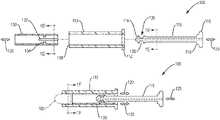
- FIG. 1Ais a sectional view of a single-use suppository insertion device according to an example embodiment of the invention illustrating the device in an unassembled state;
- FIG. 1Bis a sectional view of the single-use suppository insertion device of FIG. 1A in an assembled state
- FIG. 1Cis a sectional view of the single-use suppository insertion device of FIG. 1B in a locked state, e.g., after insertion of the suppository;
- FIG. 1Dis a sectional view of the insert of the device of FIG. 1A ;
- FIG. 1Eis a sectional view of the plunger of the device of FIG. 1A ;
- FIG. 1Fis a sectional view of the insertion device of FIG. 1B ;
- FIG. 2is a sectional view of a single-use suppository insertion device according to another example embodiment
- FIG. 3Ais a sectional view of a single-use suppository insertion device according to yet another example embodiment of the invention illustrating the device in an unassembled state;
- FIG. 3Bis a sectional view of the single-use suppository insertion device of FIG. 3A in an assembled state
- FIG. 3Cis a sectional view of the single-use suppository insertion device of FIG. 3B in a locked state, such as after insertion of the suppository;
- FIG. 3Dis a sectional view of the barrel of the device of FIG. 3A ;
- FIG. 3Eis a sectional view of the plunger of the device of FIG. 3A ;
- FIG. 3Fis a sectional view of the device of FIG. 3B ;
- FIG. 3Gillustrates an example break-away locking mechanism
- FIG. 3Hillustrates an example removable locking mechanism
- FIG. 4Ais a sectional view of a single-use suppository insertion device according to another example embodiment of the invention illustrating the device in an unassembled state;
- FIG. 4Bis a sectional view of the single-use suppository insertion device of FIG. 4A in an assembled state
- FIG. 4Cis a sectional view of the single-use suppository insertion device of FIG. 4B in a locked state
- FIG. 4Dis a sectional view of the barrel of the device of FIG. 4A ;
- FIG. 4Eis a sectional view of the plunger of the device of FIG. 4A ;
- FIG. 5is a sectional view of a single-use suppository insertion device according to another example embodiment
- FIG. 6Ais a sectional view of a barrel of an insertion device according to another example embodiment
- FIG. 6Bis a sectional view of the barrel of FIG. 6A illustrating the perforated flange.
- a ratchetis commonly understood to be a locking device or mechanism that permits movement of a part of an apparatus in one direction only, e.g., a lever or spring-loaded catch.
- a ratchetcan include a pawl or detent for preventing backward motion while allowing forward motion of an element of the ratchet.
- FIGS. 1A to 1Fillustrates an example embodiment of an applicator (insertion device) 100 configured to insert a suppository, e.g., a rectal suppository, 105 into a human or animal according to an embodiment of the present invention.
- the insertion device 100is configured for one-time use, as further described below.
- the device 100can include means for activating a disabling feature of the plunger or the barrel during operational motion of the plunger relative to the barrel, which may be during insertion of or withdrawal away from a suppository.
- the device 100can include a barrel 110 and a plunger 115 .
- the barrel 110has a gripping end 112 and an insertion end 108 and can be appropriately sized and shaped to fit within a patient's anal canal.
- the barrel 110is further configured to define a gas flow path 120 allowing gas to freely flow through the barrel 110 when positioned within the anal canal.
- the plunger 115which has a gripping end (e.g., a finger interface end) 116 and an insertion end 114 , is appropriately sized and shaped to extend through the barrel 110 .
- a stepped portion 118is provided at the gripping end 116 of the plunger.
- the stepped portion 118can be configured to ensure that a gas flow path associated with the device 100 , e.g., gas flow path 120 , is not obstructed during use of the device.
- the plunger 115can be configured to be substantially longer than the barrel, thereby allowing the plunger 115 to extend beyond the end of the barrel 110 .
- the barrel 110may be approximately 4 cm in length whereas the plunger 115 may be approximately 8 cm in length.
- the plunger 115is configured to be movably (e.g., slidably) coupled to the barrel 110 .
- the plunger 115may be further configured to maintain a second gas flow path 125 that allows gas to freely flow through the plunger 115 as the plunger is withdrawn from the rectum and anal canal after the suppository 105 has been inserted to a desired position.
- the barrel 110maintains a gas flow path 120 allowing gas to escape.
- the plunger's gas flow path 125 and the barrel's gas flow path 120are maintained as the plunger is withdrawn from the suppository 105 , and the barrel 110 and plunger 115 are removed from the patient's anal canal.
- the gas flow paths, 125 and 120allow gas to escape as the barrel 110 and the plunger 115 are removed from the body preventing or reducing the need to release the gas in the form of flatulence
- the device 100can further include an insert 130 receivable in the barrel 110 and configured to couple to the plunger 115 .
- the insert 130can include, or provide, the disabling feature configured to be activated during operational motion of the plunger 115 relative to the barrel 110 , for example, during insertion of or withdrawal away from a suppository.
- the plunger 115can include a fitting 135 to couple to the insert 130 .
- the insert 130includes one or more protrusions 134 that extend inward from an inside wall of the insert.
- the fitting 135 of the plunger 115includes one or more complementary features 136 to engage the one or more protrusions 134 of the insert.
- the fitting 135is configured to couple to the insert 130 and apply a force to the insert to cause a portion of the insert to expand.
- the barrel 110can be configured to restrain expansion of the insert 130 , such as while the insert 130 is at least partially within the barrel.
- Other ways of coupling the plunger 115 to the insert 130 and allowing the insert to expandmay be used.
- the insert 130fits within the barrel 110 and allows for gas flow path(s) to be maintained.
- the insert 130can be configured to expand, once coupled to the plunger 115 , to prevent re-use of the insertion device 100 .
- the insert 130can include one or more longitudinal slots 132 at one end of the insert. The slots 132 allow the insert 130 to expand, e.g., to flare or increase in circumference.
- FIG. 1Cwhen the insert 130 is pushed beyond the insertion end 108 of barrel 110 by action of the plunger 115 , the insert expands due to the interaction of the fitting 135 and the insert 130 .
- the expanded insert 130 ′has a flared end 131 that cannot pass back into the barrel, thereby preventing retraction of the plunger 115 and re-loading of the device 100 with another suppository.
- the insert 130can also be manufactured in an expanded state, such as shown in FIG. 1C , and then constrained within the barrel during assembly of the device 100 . The insert is allowed to return to its expanded state by action of the plunger 115 .
- the plunger 115can engage with the insert 130 before or after loading of the suppository 105 .
- the fitting 135is positioned at the insertion end 114 of the plunger 115 , but may be positioned anywhere along the length of the plunger.
- the device 200includes a barrel 210 , a plunger 215 and an insert 230 .
- FIG. 2shows device 200 in a locked state, such as after insertion of a suppository. In the locked state of device 200 , the plunger 215 and insert 230 will not move backward.
- the plunger 215 and insert 230are similar to the plunger 115 and insert 130 of FIG. 1A .
- the barrel 210includes structural elements 240 that extend inwardly.
- the structural elements 240can be fins or other spacing elements that are configured to maintain a gas flow path associated with the barrel 210 .
- the insert 230can be dislodged from a position within the barrel 210 , by action of the plunger 215 , and can expand at the back end, as illustrated in FIG. 2 .
- the expanded back end 231 of insert 230engages with the structural elements 240 , in a ratchet-like fashion, to prevent backward movement of the insert 230 .
- the plunger 215is coupled to the insert 230 , the plunger 215 is also prevented from moving backward, e.g., retracting out of the barrel 210 . In this way, the insert 230 cannot be returned to a position within the barrel 210 .
- the insert 230provides the disabling feature that, in cooperation with the fins 240 , prevents re-use of the device 200 .
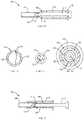
- FIGS. 3A-3Fillustrate an alternative embodiment of an insertion device 300 that includes a barrel 310 and a plunger 315 configured to be movably coupled to the barrel.
- the barrel 310has an insertion end 308 and a gripping end 312 , and further includes structural elements, e.g., fins 340 , which can function as spacing elements to maintain a gas flow path 320 associated with the device 300 .
- fins 340There may be four fins 340 , as illustrated in FIG. 3D , and the fins can provide a space 321 within the barrel 310 for receiving the plunger 315 .
- the plunger 315has a gripping end (e.g., a finger interface end) 316 and an insertion end 314 .
- the plunger 315is appropriately sized and shaped to extend through the barrel 310 .
- a stepped portion 318is provided at the gripping end 316 of the plunger 315 .
- the stepped portion 318can be configured to ensure that a gas flow path associated with the device 300 , e.g., gas flow path 320 , is not obstructed during use of the device.
- the plunger 315can be configured to be substantially longer than the barrel 310 , thereby allowing the plunger 315 to extend beyond the insertion end 308 of the barrel 310 .
- one or more flaps 345are provided that extend outward from an outer surface of the plunger 315 .
- the flaps 345can extend outward from plunger 315 at an acute angle and in a direction away from insertion end 314 of the plunger.
- the flaps 345can be resilient and may be spring-loaded.
- the flaps 345can be configured to bend, e.g., elastically deform, when compressed against the plunger 315 by fins 340 , such as when the plunger is advanced into the barrel.
- the flaps 345can be sized and shaped such that the fins 340 will bend the flaps irrespective of the relative rotation of the plunger and the barrel.
- FIGS. 3B and 3Cillustrate two different stages of advancement of the plunger 315 into barrel 310 .
- the flaps 345are bent and held close to the plunger 315 as they pass through the portion of the barrel 310 that includes the fins 340 .
- the flaps 345expand after passing past the end of the fin portion of the barrel 310 .
- the expanded flaps 345engage the fins 340 and prevent retraction of the plunger 315 , locking the plunger against the barrel and thereby preventing re-use of the device 300 .
- the flaps 345provide a disabling feature that, in cooperation with the fins 340 , prevents re-use of the device 300 .
- the fins 340can include a feature complementary to the flaps 345 .
- the finscan include a concave surface to engage the tips of the flaps 345 .
- the fins 340 and flaps 345can form a ratchet mechanism.
- the plunger 315may be further configured to maintain a second gas flow path 325 ( FIGS. 3A and 3E ) that allows gas to freely flow through the plunger 315 as the plunger is withdrawn from the rectum and anal canal after the suppository has been inserted to a desired position.
- FIG. 3Dis a sectional view of the barrel 310 of the device 300 of FIG. 3A .
- Four fins 340extend into an inner lumen of the barrel and provide space 321 for the plunger 315 .
- FIG. 3Eis a sectional view of the plunger 315 of the device 300 of FIG. 3A , illustrating the gas flow path 325 that extends through the body of the plunger 315 . Also shown are two flaps 345 that extend radially outward from the body of the plunger.
- FIG. 3Fis a sectional view of the device 300 of FIG. 3B , illustrating a stage of advancement of the plunger 315 into barrel 310 , including compression of flaps 345 by fins 340 , as described above. Also shown is gas flow path(s) 320 , maintained between the plunger 315 and barrel 310 .
- a mechanismcan be provided to prevent premature advancement of the plunger into the barrel, thus preventing premature activation of the disabling feature.
- the mechanismcan be an insert or a component of the barrel, the plunger, or both.
- the insert or componentcan prevent the device from locking prematurely, such as while a user is handling the device, loading the suppository, or at any other time before the suppository has been delivered.
- the mechanismcan include a break-away locking mechanism or a removable clip or cuff, as will be described next with respect to FIGS. 3G and 3H .
- FIGS. 3G and 3Hillustrate two example components that can prevent the insertion device from locking prematurely by preventing the plunger from moving forward prematurely.
- FIG. 3Gillustrates insertion device 300 ′ that is similar to device 300 , except that a break-away member 350 is provided to couple barrel 310 ′ and plunger 315 ′ of the device.
- the break-away member 350keeps the plunger 315 ′ from moving relative to the barrel 310 ′ and, thus, prevents engagement of the disabling feature.
- the break-away member 350is configured to break away from the barrel 310 ′ and plunger 315 ′ at break points 352 and 354 , respectively.
- the plungercan be advanced into the barrel and the disabling feature (e.g., flaps 345 ′) can engage the structural element (e.g., fins 340 ′) of the barrel.
- the disabling featuree.g., flaps 345 ′
- the structural elemente.g., fins 340 ′
- FIG. 3Hillustrates a removable cuff 355 applied to the plunger 315 of the device 300 .
- the cuff 355is sized and shaped to prevent the plunger 315 from moving forward into the barrel 310 until the cuff is removed. This feature can prevent premature engagement of the disabling feature (e.g., flaps 345 ) with the structural element (e.g., fins 340 ).
- the break-away member 350 and cuff 355can be made of the same material as the plunger and the barrel, such as plastic, elastomer, paper, or other suitable material.
- the break-away member 350 and cuff 355can each be separate component or can be co-manufactured (e.g., co-molded) with the plunger, the barrel, or both.
- Each mechanism 350 , 355can be configured to be removed by the user, e.g., broken off, torn off, released, etc., when the user is ready to administer the suppository.
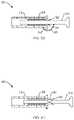
- FIGS. 4A-4Eillustrate another example embodiment of a single-use suppository insertion device 400 .
- the device 400includes a barrel 410 and a plunger 415 that is configured to be movably coupled to the barrel.
- the barrel 410include fins 440 , which can be spacing elements configured to maintain a gas flow path 420 associated with the device 400 , such as gas flow paths described with respect to device 100 of FIG. 1A .
- there can be four fins 440extending inward from an inside wall of the barrel 410 at equally spaced intervals.
- the fins 440can define a space 421 for plunger 415 .
- the plunger 415includes an insertion end 414 , which is wider than a mid-portion of the plunger, and a finger interface end 416 , which includes a stepped portion 418 and which may include a cup-shaped interface portion for interfacing with the user's fingertip.
- a protrusion 460is positioned along the length of the plunger 415 , between the insertion end 414 and the finger interface end 416 .
- the protrusion 460is a conical-shaped feature (having a triangular cross-sectional profile) that extends outward from an outer surface of the plunger 415 , as illustrated in FIG. 4A and in sectional view in FIG. 4E .
- the protrusion 460can be formed integrally with the body of the plunger 415 . Alternatively, the protrusion 460 can be glued, bonded, or otherwise attached to the body of the plunger 415 .
- the plunger 415can be solid or hollow and can be configured to define a gas flow path through the plunger, such as is the case with plunger 115 of FIG. 1A .
- FIG. 4Ashows the device 400 pre-assembly
- FIG. 4Bshows the device in an assembled state, where the plunger 415 has been partially inserted into the barrel 410 .
- the insertion portion 414 of the plungeris positioned past the end of the fins 440 .
- the protrusion 460is positioned at the gripping end 412 of the barrel, before the fins 440 .
- FIG. 4Cillustrates the device 400 locked after first use, the plunger 415 having been advanced further into the barrel 410 .
- the protrusion 460is positioned in respective slots 442 of the fins 440 .
- the plunger 415is locked in that it cannot be retracted from the barrel 410 because the engagement of the protrusion 460 and the fins 440 .
- the protrusion 460 and the fins 440can form a ratchet.
- FIG. 5illustrates a single-use suppository insertion device 500 according to another example embodiment.
- device 500includes a barrel 510 having fins 540 and also includes a plunger 515 slidably disposed in the barrel and having protrusion 560 .
- locking of the plunger to the barreloccurs at a different position within the barrel as compared to device 400 .
- fins 540 of device 500do not include a slot to receive protrusion 560 . Instead, protrusion 560 engages fins 540 in a locking fashion once the protrusion 560 has been advanced past the end of the fins 540 , as illustrated in FIG. 5 .
- FIGS. 6A-6Billustrate a barrel 610 of an insertion device according to another example embodiment.
- Barrel 610can be used with any of the plungers described herein, such as plungers 115 , 215 , 315 , 315 ′, 415 and 515 .
- a flange 670couples a structural element 665 to the barrel 610 .
- the structural element 665is a spacing element.
- the flange 670is configured to break at a perforation 672 ( FIG. 6B ) of the flange to cause the structural element 665 to uncouple from the barrel 610 when a user attempts to retract the plunger after one-time use of the insertion device.
- Uncoupling of the element 665 from the barrel 610is irreversible and renders the device in-operable.
- the plungercan be coupled to an insert or can include a protrusion or flap, as described herein, to engage the structural element 665 . Engagement occurs by movement of the plunger relative to barrel, such as when the user advances the plunger during insertion of the suppository or when the user withdraws the plunger from the suppository.
- the structural element 665can break away, such that the plunger is no longer engaged with the barrel. This can leave the plunger to rattle around in the barrel.
- a single-use suppository insertion device 100 , 200 , 300 , 300 ′, 400 , 500that include a barrel, a plunger and a disabling feature.
- Embodiments of the single-use suppository insertion devicecan further include a structural element of the barrel or the plunger configured to engage with the disabling feature of the barrel or the plunger during insertion of or withdrawal away from the suppository to activate the disabling feature.
- the structural elementcan be configured to engage irreversibly with the disabling feature and can include a feature complementary to the disabling feature.
- the complementary feature of the structural elementcan include a concave surface
- the disabling featurecan include a convex surface.
- the structural elementcan extend from an inner surface of the barrel and can be a spacing element.
- the disabling featurecan be a protrusion extending outward from an outer surface of the plunger.
- the disabling feature and the structural elementcan form a ratchet.
- the structural elementcan be coupled to or defined by the barrel, and the disabling feature can be coupled to or defined by the plunger. Engagement of the disabling feature with the structural element can cause the structural element to uncouple from the barrel.
- the structural elementcan be configured to engage with the disabling feature during withdrawal of the plunger through the barrel.
Landscapes
- Health & Medical Sciences (AREA)
- Engineering & Computer Science (AREA)
- Anesthesiology (AREA)
- Biomedical Technology (AREA)
- Heart & Thoracic Surgery (AREA)
- Hematology (AREA)
- Life Sciences & Earth Sciences (AREA)
- Animal Behavior & Ethology (AREA)
- General Health & Medical Sciences (AREA)
- Public Health (AREA)
- Veterinary Medicine (AREA)
- Infusion, Injection, And Reservoir Apparatuses (AREA)
Abstract
Description
Claims (23)
Priority Applications (1)
| Application Number | Priority Date | Filing Date | Title |
|---|---|---|---|
| US16/098,623US11298515B2 (en) | 2016-05-12 | 2017-05-11 | Single-use suppository insertion device and method |
Applications Claiming Priority (3)
| Application Number | Priority Date | Filing Date | Title |
|---|---|---|---|
| US201662335179P | 2016-05-12 | 2016-05-12 | |
| US16/098,623US11298515B2 (en) | 2016-05-12 | 2017-05-11 | Single-use suppository insertion device and method |
| PCT/US2017/032142WO2017197100A1 (en) | 2016-05-12 | 2017-05-11 | Single-use suppository insertion device and method |
Related Parent Applications (1)
| Application Number | Title | Priority Date | Filing Date |
|---|---|---|---|
| PCT/US2017/032142A-371-Of-InternationalWO2017197100A1 (en) | 2016-05-12 | 2017-05-11 | Single-use suppository insertion device and method |
Related Child Applications (1)
| Application Number | Title | Priority Date | Filing Date |
|---|---|---|---|
| US17/709,125DivisionUS12156984B2 (en) | 2016-05-12 | 2022-03-30 | Single-use suppository insertion device and method |
Publications (2)
| Publication Number | Publication Date |
|---|---|
| US20190143088A1 US20190143088A1 (en) | 2019-05-16 |
| US11298515B2true US11298515B2 (en) | 2022-04-12 |
Family
ID=58800904
Family Applications (3)
| Application Number | Title | Priority Date | Filing Date |
|---|---|---|---|
| US16/098,623Active2037-09-24US11298515B2 (en) | 2016-05-12 | 2017-05-11 | Single-use suppository insertion device and method |
| US17/709,125Active2037-09-04US12156984B2 (en) | 2016-05-12 | 2022-03-30 | Single-use suppository insertion device and method |
| US18/933,111PendingUS20250050083A1 (en) | 2016-05-12 | 2024-10-31 | Single-use suppository insertion device and method |
Family Applications After (2)
| Application Number | Title | Priority Date | Filing Date |
|---|---|---|---|
| US17/709,125Active2037-09-04US12156984B2 (en) | 2016-05-12 | 2022-03-30 | Single-use suppository insertion device and method |
| US18/933,111PendingUS20250050083A1 (en) | 2016-05-12 | 2024-10-31 | Single-use suppository insertion device and method |
Country Status (7)
| Country | Link |
|---|---|
| US (3) | US11298515B2 (en) |
| EP (1) | EP3454933B1 (en) |
| JP (1) | JP7061967B2 (en) |
| CN (1) | CN109152912B (en) |
| CA (1) | CA3023666A1 (en) |
| MX (2) | MX2018013823A (en) |
| WO (1) | WO2017197100A1 (en) |
Cited By (3)
| Publication number | Priority date | Publication date | Assignee | Title |
|---|---|---|---|---|
| US12156984B2 (en) | 2016-05-12 | 2024-12-03 | Cristcot Llc | Single-use suppository insertion device and method |
| US12337130B2 (en) | 2012-10-19 | 2025-06-24 | Cristcot Llc | Suppository insertion device, suppository, and method of manufacturing a suppository |
| US12396946B1 (en) | 2024-12-30 | 2025-08-26 | Cristcot Llc | Methods of treating gastrointestinal diseases and disorders |
Families Citing this family (2)
| Publication number | Priority date | Publication date | Assignee | Title |
|---|---|---|---|---|
| US9662481B2 (en) | 2008-10-07 | 2017-05-30 | Cristcot Llc | Method and apparatus for inserting a rectal suppository |
| CN108175926B (en)* | 2017-12-29 | 2021-02-23 | 鄂东医疗集团市中心医院(市普爱医院、湖北理工学院附属医院) | Novel urethra ware of dosing for uropoiesis surgery |
Citations (114)
| Publication number | Priority date | Publication date | Assignee | Title |
|---|---|---|---|---|
| US330764A (en) | 1885-11-17 | Road scraper and leveler | ||
| US504512A (en) | 1893-09-05 | bailey | ||
| US2281600A (en) | 1939-09-02 | 1942-05-05 | Emma Elizabeth Ross | Dilator |
| US2290571A (en) | 1940-04-03 | 1942-07-21 | Peyton Thomas Roy | Rectal dilator |
| US2443207A (en) | 1945-06-11 | 1948-06-15 | Addington C Tedford | Rectal dilator |
| US2503445A (en) | 1947-10-24 | 1950-04-11 | Celluplastic Corp | Applicator |
| US2532598A (en) | 1947-12-08 | 1950-12-05 | Surgident Ltd | Guard device for syringes for use with heat-fluent materials |
| US2680442A (en) | 1952-04-04 | 1954-06-08 | Frank L Linzmayer | Disposable suppository casing |
| US2709436A (en) | 1953-07-23 | 1955-05-31 | Celluplastic Corp | Disposable applicator |
| US2754823A (en) | 1955-04-29 | 1956-07-17 | Miller Lab Inc | Suppository applicator |
| FR1190750A (en) | 1957-10-17 | 1959-10-14 | Packaging mold for suppositories serving at the same time as a device for their introduction | |
| US3015332A (en) | 1957-02-25 | 1962-01-02 | Personal Products Corp | Applicator |
| US3139886A (en) | 1962-09-12 | 1964-07-07 | Richard B Tallman | Tampon applicator with lubricating feature |
| US3220413A (en) | 1961-04-03 | 1965-11-30 | Sunnen Joseph | Applicator |
| US3667465A (en) | 1969-12-08 | 1972-06-06 | Kimberly Clark Co | Applicator tubes for suppositories and the like |
| US3780735A (en) | 1972-02-03 | 1973-12-25 | J Crouter | Dose syringe |
| US3835856A (en) | 1972-02-29 | 1974-09-17 | Hahn C Gmbh | Tampon applicator |
| US3840010A (en) | 1970-05-11 | 1974-10-08 | F Giglio | Suppository |
| US4248229A (en) | 1979-05-16 | 1981-02-03 | Miller Roscoe E | Enema tip retention apparatus |
| DE3031408A1 (en) | 1980-08-20 | 1982-03-25 | Fritz 7015 Korntal-Münchingen Mächtle | Lead=in instrument for suppositories - with piston in open cylinder forming bottom of receptacle for suppository |
| US4341221A (en) | 1980-10-07 | 1982-07-27 | Medtronic, Inc. | Shielded recording electrode system |
| US4341211A (en) | 1981-09-08 | 1982-07-27 | Kline Larry H | Lubricating object applicator |
| US4361150A (en) | 1980-04-07 | 1982-11-30 | Voss Joseph A | Extruded plastic hygienic applicator |
| US4406655A (en) | 1978-08-28 | 1983-09-27 | Clayton Ralph S | Colon cleansing system and technique |
| US4421504A (en) | 1981-09-08 | 1983-12-20 | Kline Larry H | Lubricating object injector utilizing a single plunger |
| JPS59181834U (en) | 1983-05-21 | 1984-12-04 | 佐藤 晃 | Structure of suppositories |
| US4752288A (en) | 1985-02-04 | 1988-06-21 | Aid-Pack, Inc. | Disposable enema unit |
| JPH02302266A (en) | 1989-04-28 | 1990-12-14 | Flp Enterp Inc | No-reuse syringe |
| US4990136A (en) | 1989-10-12 | 1991-02-05 | Warner-Lambert Company | Suppository applicator |
| US5152068A (en) | 1991-09-03 | 1992-10-06 | Meister Lanny M | Aiming device for archery |
| USD330764S (en) | 1989-09-29 | 1992-11-03 | Lena Lorentzon | Rectal applicator for pharmaceutical products |
| US5160689A (en) | 1990-11-16 | 1992-11-03 | Revlon Consumer Products Corporation | Apparatus and method for manufacturing cosmetic products |
| US5213566A (en) | 1991-07-02 | 1993-05-25 | Ortho Pharmaceutical Corporation | Prefilled suppository applicator |
| JPH0570545U (en) | 1992-03-03 | 1993-09-24 | 積水化学工業株式会社 | Suppository package |
| JPH05279243A (en) | 1992-02-03 | 1993-10-26 | Shiroyuki Hori | Shape of inserting medicine |
| US5330427A (en) | 1991-07-02 | 1994-07-19 | Ortho Pharmaceutical Corporation | Prefilled suppository applicator |
| US5352681A (en) | 1991-06-07 | 1994-10-04 | Byk Nederland Bv | Pharmaceutical enema preparation |
| US5354325A (en) | 1991-07-26 | 1994-10-11 | Institut National De La Sante Et De La Recherche Medicale | System for internal heat treatment of a specific body and its use |
| US5460617A (en) | 1994-07-28 | 1995-10-24 | Abbott Laboratories | Syringe plunger with intermediate pushing surface |
| JPH09103467A (en) | 1995-06-08 | 1997-04-22 | Ortho Pharmaceut Corp | Preparation of suppository for vagina in unit dosage applicator and suppository prepared by the method |
| US5662601A (en) | 1995-12-08 | 1997-09-02 | Snead; Patty B. | Suppository applicator |
| US5788664A (en) | 1994-11-30 | 1998-08-04 | Scalise; Gaspare | Suppository applicator |
| US5860946A (en) | 1996-07-05 | 1999-01-19 | Novo Nordisk A/S | Instrument for inserting a suppository |
| US6056714A (en) | 1995-07-14 | 2000-05-02 | Playtex Products, Inc. | Supporting rim structure of an open insertion end tampon applicator used to post form an insertion end of a tampon pledget |
| EP1040808A2 (en) | 1999-03-31 | 2000-10-04 | Uni-Charm Corporation | Applicator for sanitary tampon |
| USD436661S1 (en) | 1999-05-20 | 2001-01-23 | Melvin P Berry | Suppository applicator |
| CN2416896Y (en) | 1999-06-02 | 2001-01-31 | 赵得华 | Easy-to-be-opened type package box for suppository |
| US6190348B1 (en) | 1996-04-10 | 2001-02-20 | Harris A. Tiemann | Disposable applicator |
| JP2001070456A (en) | 1999-09-08 | 2001-03-21 | Toru Ubukata | Suppository insertion appliance |
| US6245776B1 (en) | 1999-01-08 | 2001-06-12 | 3M Innovative Properties Company | Formulations and methods for treatment of mucosal associated conditions with an immune response modifier |
| WO2001091605A1 (en) | 2000-05-31 | 2001-12-06 | Wyeth | Multi-composition stick product and a process and system for manufacturing the same |
| US20020048601A1 (en) | 2000-07-07 | 2002-04-25 | Anestic Aps | Suppository and composition comprising at least one polyethylene glycol |
| US6380455B1 (en) | 1999-12-28 | 2002-04-30 | Kimberly-Clark Worldwide, Inc. | Feminine sanitary protection package and method |
| US20020058674A1 (en) | 1999-01-08 | 2002-05-16 | Hedenstrom John C. | Systems and methods for treating a mucosal surface |
| US6486168B1 (en) | 1999-01-08 | 2002-11-26 | 3M Innovative Properties Company | Formulations and methods for treatment of mucosal associated conditions with an immune response modifier |
| US6500460B1 (en) | 1998-04-21 | 2002-12-31 | Infection-Recherche Inc. | Formulations for the prevention or the treatment of diseases affecting mucosae or skin, or for pregnancy prevention, and an applicator for the delivery of topical formulations into mucosal cavities |
| USD471980S1 (en) | 2002-05-09 | 2003-03-18 | Becton, Dickinson And Company | Medical needle assembly |
| US20030088217A1 (en) | 2000-10-20 | 2003-05-08 | Bergeron Michel G. | Applicator for the delivery of topical formulations into mucosal cavities |
| EP1319420A1 (en) | 2001-12-13 | 2003-06-18 | Carmelo Mauro | Device for introducing suppositores |
| WO2003101525A1 (en) | 2002-05-31 | 2003-12-11 | Reza Hezari | Suppository applicator |
| US20030233077A1 (en) | 2002-06-14 | 2003-12-18 | Mcneil-Ppc, Inc. | Applicator device for suppositories and the like |
| US20030233078A1 (en) | 2002-06-14 | 2003-12-18 | Mcneil-Ppc, Inc. | Applicator device for suppositories and the like |
| JP2004526520A (en) | 2001-04-13 | 2004-09-02 | ベクトン・ディキンソン・アンド・カンパニー | Pre-fillable intradermal syringe |
| US6786883B2 (en) | 2002-04-15 | 2004-09-07 | Ronald D. Shippert | Applicator for insertion of cargo into a body cavity |
| US20040249352A1 (en) | 2002-06-14 | 2004-12-09 | Swick Paul B. | Applicator device for medicated materials |
| US20040249416A1 (en) | 2003-06-09 | 2004-12-09 | Yun Anthony Joonkyoo | Treatment of conditions through electrical modulation of the autonomic nervous system |
| US20040260252A1 (en) | 2003-01-16 | 2004-12-23 | Femmepharma, Inc. | Vaginal or rectal applicator |
| WO2004112755A1 (en) | 2003-06-18 | 2004-12-29 | John Michael Newton | Controlled release devices with lumens |
| US20050004533A1 (en) | 2003-06-27 | 2005-01-06 | Alan Smith | Device and method for rectal lavage |
| EP1530978A1 (en) | 2002-07-02 | 2005-05-18 | Terumo Kabushiki Kaisha | Syringe and prefilled syringe |
| US20050143788A1 (en) | 2003-12-29 | 2005-06-30 | Yun Anthony J. | Treatment of female fertility conditions through modulation of the autonomic nervous system |
| US20050143378A1 (en) | 2003-12-29 | 2005-06-30 | Yun Anthony J. | Treatment of conditions through pharmacological modulation of the autonomic nervous system |
| US6916308B2 (en) | 2000-06-08 | 2005-07-12 | Cook Incorporated | High pressure injection syringe |
| US20050153885A1 (en) | 2003-10-08 | 2005-07-14 | Yun Anthony J. | Treatment of conditions through modulation of the autonomic nervous system |
| US20050240241A1 (en) | 2003-06-09 | 2005-10-27 | Yun Anthony J | Treatment of conditions through modulation of the autonomic nervous system |
| US20050256028A1 (en) | 2004-05-13 | 2005-11-17 | Yun Anthony J | Treatment of conditions through modulation of the autonomic nervous system during at least one predetermined menstrual cycle phase |
| US20050273038A1 (en) | 2004-06-04 | 2005-12-08 | The Procter & Gamble Company | Tampon applicator providing low placement |
| US20060035974A1 (en) | 2004-08-05 | 2006-02-16 | Yun Anthony J | Linoleic acid active agents for enhancing probability of becoming pregnant |
| US20060034847A1 (en) | 2004-08-11 | 2006-02-16 | Yun Anthony J | Methods of treating a subject for a condition |
| US20060069012A1 (en) | 2004-09-29 | 2006-03-30 | Yun Anthony J | Methods and compositions for treating plasticity in a subject |
| WO2006063377A1 (en) | 2004-12-14 | 2006-06-22 | Global Medisafe Holdings Pty Limited | Extendable auto retractable medical syringe |
| US7070581B2 (en) | 2002-04-05 | 2006-07-04 | Comar, Inc. | Dispenser for medicaments and method and apparatus for making same |
| US20060161105A1 (en)* | 2003-06-27 | 2006-07-20 | Akihide Mori | Disposable injector |
| US7081110B2 (en) | 2003-07-17 | 2006-07-25 | The Procter & Gamble Company | Applicator having an indented fingergrip with raised portions |
| WO2006077617A1 (en) | 2005-01-18 | 2006-07-27 | Nishihara, Risa | Apparatus for caring dead body |
| US20060184100A1 (en) | 2004-03-01 | 2006-08-17 | Joel Studin | Breast implant introducer |
| US20060206149A1 (en) | 2005-02-04 | 2006-09-14 | Yun Anthony J | Methods and compositions for treating a disease condition in a subject |
| USD529603S1 (en) | 2003-10-17 | 2006-10-03 | Ferndale Laboratories, Inc. | Dispenser tip assembly for applying a medication to mucosal tissue |
| US7122025B1 (en) | 1999-10-06 | 2006-10-17 | Astra Tech Ab | Rectal insertion device |
| US20070073267A1 (en) | 2005-09-27 | 2007-03-29 | Mile Creek Capital, Llc | Low-loss multi-lumen injection apparatus |
| US20070112327A1 (en) | 2005-11-03 | 2007-05-17 | Yun Anthony J | Methods and compositions for treating a renal disease condition in a subject |
| US20070129668A1 (en) | 2002-06-14 | 2007-06-07 | Mcneil-Ppc, Inc. | Applicator device for suppositories and the like |
| JP2007215732A (en) | 2006-02-16 | 2007-08-30 | Meibin Ko | Drug administration apparatus |
| US20080038377A1 (en) | 2006-08-09 | 2008-02-14 | Citow Jonathan S | Device for treatment of inflamed tissue |
| US7361168B2 (en) | 2004-04-21 | 2008-04-22 | Acclarent, Inc. | Implantable device and methods for delivering drugs and other substances to treat sinusitis and other disorders |
| US20080097286A1 (en) | 2006-08-04 | 2008-04-24 | 0696578 B.C. Ltd Incorporation | Anal ointment applicator |
| USD572362S1 (en) | 2003-04-04 | 2008-07-01 | Playtex Products, Inc. | Tampon applicator with finger grip |
| US20080161752A1 (en) | 2006-12-29 | 2008-07-03 | Rajala Gregory J | Delivery device |
| US20080167598A1 (en) | 2007-01-10 | 2008-07-10 | The Procter & Gamble Company | Active applicator |
| US20080167599A1 (en) | 2007-01-10 | 2008-07-10 | The Procter & Gamble Comapny | Active applicator |
| WO2008102341A2 (en) | 2007-02-20 | 2008-08-28 | Svip 3 Llc | Fecal incontinence device, kit and method |
| USD579786S1 (en) | 2005-12-22 | 2008-11-04 | Medical Instill Technologies, Inc. | Dispenser |
| US20080319269A1 (en) | 2005-08-09 | 2008-12-25 | Antonio Longo | Rectally Insertable Surgical System |
| USD585988S1 (en) | 2006-03-13 | 2009-02-03 | Kimbra D. Kinnard | Intestinal excrement removal tool |
| US7503895B2 (en) | 1999-10-05 | 2009-03-17 | Omnisonics Medical Technologies, Inc. | Ultrasonic device for tissue ablation and sheath for use therewith |
| FR2923999A1 (en) | 2007-11-26 | 2009-05-29 | Tokiwa Corp | Cosmetic material e.g. lipstick, dispensing container, has movable body moved back, so that aspiration force is applied based on rear movement of extrusion portion, and material is withdrawn in filling element |
| US20100010471A1 (en) | 2006-07-17 | 2010-01-14 | Euro-Celtique S.A. | Medication applicator device |
| WO2010042468A2 (en) | 2008-10-07 | 2010-04-15 | Christcot Medical Company | Method and apparatus for inserting a rectal suppository |
| US20100145379A1 (en) | 2007-01-16 | 2010-06-10 | Radiadyne, Llc | Rectal Balloon Apparatus with Pressure Relieving Lumen and Sensors |
| CN201586319U (en)* | 2010-01-05 | 2010-09-22 | 刘序会 | Disposable female suppository administration device |
| JP2012005719A (en) | 2010-06-25 | 2012-01-12 | Rohto Pharmaceutical Co Ltd | Applicator |
| EP2554211A1 (en)* | 2011-08-05 | 2013-02-06 | Laboratorios Leon Farma SA | Instrument for inserting a suppository |
| US20130204182A1 (en)* | 2008-10-07 | 2013-08-08 | Christcot Medical Company | Method and apparatus for inserting a rectal suppository |
| WO2014063122A1 (en) | 2012-10-19 | 2014-04-24 | Christcot Inc. | Suppository insertion device, suppository, and method of manufacturing a suppository |
Family Cites Families (7)
| Publication number | Priority date | Publication date | Assignee | Title |
|---|---|---|---|---|
| WO1984000495A1 (en)* | 1982-07-23 | 1984-02-16 | Larry Harold Kline | Lubricating object applicator |
| CN2048757U (en)* | 1989-04-15 | 1989-12-06 | 盛坤贤 | Whole dosage drug-supply device for cavity and canal |
| CN2213544Y (en)* | 1994-12-03 | 1995-11-29 | 鞍山钢铁公司 | rectal suppository applicator |
| US20110002966A1 (en)* | 2009-07-01 | 2011-01-06 | Alex Lovett | Vaginal Suppository System and Method |
| US20130123712A1 (en)* | 2011-11-11 | 2013-05-16 | Becton, Dickinson And Company | Plunger Rod Retaining Anchors |
| CN202682540U (en)* | 2012-07-24 | 2013-01-23 | 娄飞 | Disposal gel unfolder |
| EP3454933B1 (en) | 2016-05-12 | 2025-08-27 | Cristcot LLC | Single-use suppository insertion device and method |
- 2017
- 2017-05-11EPEP17726748.1Apatent/EP3454933B1/enactiveActive
- 2017-05-11CNCN201780031643.4Apatent/CN109152912B/enactiveActive
- 2017-05-11JPJP2018558134Apatent/JP7061967B2/enactiveActive
- 2017-05-11MXMX2018013823Apatent/MX2018013823A/enunknown
- 2017-05-11WOPCT/US2017/032142patent/WO2017197100A1/ennot_activeCeased
- 2017-05-11CACA3023666Apatent/CA3023666A1/enactivePending
- 2017-05-11USUS16/098,623patent/US11298515B2/enactiveActive
- 2018
- 2018-11-09MXMX2022013359Apatent/MX2022013359A/enunknown
- 2022
- 2022-03-30USUS17/709,125patent/US12156984B2/enactiveActive
- 2024
- 2024-10-31USUS18/933,111patent/US20250050083A1/enactivePending
Patent Citations (141)
| Publication number | Priority date | Publication date | Assignee | Title |
|---|---|---|---|---|
| US504512A (en) | 1893-09-05 | bailey | ||
| US330764A (en) | 1885-11-17 | Road scraper and leveler | ||
| US2281600A (en) | 1939-09-02 | 1942-05-05 | Emma Elizabeth Ross | Dilator |
| US2290571A (en) | 1940-04-03 | 1942-07-21 | Peyton Thomas Roy | Rectal dilator |
| US2443207A (en) | 1945-06-11 | 1948-06-15 | Addington C Tedford | Rectal dilator |
| US2503445A (en) | 1947-10-24 | 1950-04-11 | Celluplastic Corp | Applicator |
| US2532598A (en) | 1947-12-08 | 1950-12-05 | Surgident Ltd | Guard device for syringes for use with heat-fluent materials |
| US2680442A (en) | 1952-04-04 | 1954-06-08 | Frank L Linzmayer | Disposable suppository casing |
| US2709436A (en) | 1953-07-23 | 1955-05-31 | Celluplastic Corp | Disposable applicator |
| US2754823A (en) | 1955-04-29 | 1956-07-17 | Miller Lab Inc | Suppository applicator |
| US3015332A (en) | 1957-02-25 | 1962-01-02 | Personal Products Corp | Applicator |
| FR1190750A (en) | 1957-10-17 | 1959-10-14 | Packaging mold for suppositories serving at the same time as a device for their introduction | |
| US3220413A (en) | 1961-04-03 | 1965-11-30 | Sunnen Joseph | Applicator |
| US3139886A (en) | 1962-09-12 | 1964-07-07 | Richard B Tallman | Tampon applicator with lubricating feature |
| US3667465A (en) | 1969-12-08 | 1972-06-06 | Kimberly Clark Co | Applicator tubes for suppositories and the like |
| US3840010A (en) | 1970-05-11 | 1974-10-08 | F Giglio | Suppository |
| US3780735A (en) | 1972-02-03 | 1973-12-25 | J Crouter | Dose syringe |
| US3835856A (en) | 1972-02-29 | 1974-09-17 | Hahn C Gmbh | Tampon applicator |
| US4406655A (en) | 1978-08-28 | 1983-09-27 | Clayton Ralph S | Colon cleansing system and technique |
| US4248229A (en) | 1979-05-16 | 1981-02-03 | Miller Roscoe E | Enema tip retention apparatus |
| US4361150A (en) | 1980-04-07 | 1982-11-30 | Voss Joseph A | Extruded plastic hygienic applicator |
| DE3031408A1 (en) | 1980-08-20 | 1982-03-25 | Fritz 7015 Korntal-Münchingen Mächtle | Lead=in instrument for suppositories - with piston in open cylinder forming bottom of receptacle for suppository |
| US4341221A (en) | 1980-10-07 | 1982-07-27 | Medtronic, Inc. | Shielded recording electrode system |
| US4421504A (en) | 1981-09-08 | 1983-12-20 | Kline Larry H | Lubricating object injector utilizing a single plunger |
| US4341211A (en) | 1981-09-08 | 1982-07-27 | Kline Larry H | Lubricating object applicator |
| JPS59181834U (en) | 1983-05-21 | 1984-12-04 | 佐藤 晃 | Structure of suppositories |
| US4752288A (en) | 1985-02-04 | 1988-06-21 | Aid-Pack, Inc. | Disposable enema unit |
| JPH02302266A (en) | 1989-04-28 | 1990-12-14 | Flp Enterp Inc | No-reuse syringe |
| USD330764S (en) | 1989-09-29 | 1992-11-03 | Lena Lorentzon | Rectal applicator for pharmaceutical products |
| US4990136A (en) | 1989-10-12 | 1991-02-05 | Warner-Lambert Company | Suppository applicator |
| US5160689A (en) | 1990-11-16 | 1992-11-03 | Revlon Consumer Products Corporation | Apparatus and method for manufacturing cosmetic products |
| US5352681A (en) | 1991-06-07 | 1994-10-04 | Byk Nederland Bv | Pharmaceutical enema preparation |
| US5213566A (en) | 1991-07-02 | 1993-05-25 | Ortho Pharmaceutical Corporation | Prefilled suppository applicator |
| US5330427A (en) | 1991-07-02 | 1994-07-19 | Ortho Pharmaceutical Corporation | Prefilled suppository applicator |
| US5354325A (en) | 1991-07-26 | 1994-10-11 | Institut National De La Sante Et De La Recherche Medicale | System for internal heat treatment of a specific body and its use |
| US5152068A (en) | 1991-09-03 | 1992-10-06 | Meister Lanny M | Aiming device for archery |
| JPH05279243A (en) | 1992-02-03 | 1993-10-26 | Shiroyuki Hori | Shape of inserting medicine |
| JPH0570545U (en) | 1992-03-03 | 1993-09-24 | 積水化学工業株式会社 | Suppository package |
| US5460617A (en) | 1994-07-28 | 1995-10-24 | Abbott Laboratories | Syringe plunger with intermediate pushing surface |
| US5788664A (en) | 1994-11-30 | 1998-08-04 | Scalise; Gaspare | Suppository applicator |
| US5656283A (en) | 1995-06-08 | 1997-08-12 | Ortho Pharmaceutical Corporation | In-situ lyophilization of vaginal suppository in unit dose applicator and resultant product |
| JPH09103467A (en) | 1995-06-08 | 1997-04-22 | Ortho Pharmaceut Corp | Preparation of suppository for vagina in unit dosage applicator and suppository prepared by the method |
| US6056714A (en) | 1995-07-14 | 2000-05-02 | Playtex Products, Inc. | Supporting rim structure of an open insertion end tampon applicator used to post form an insertion end of a tampon pledget |
| US5662601A (en) | 1995-12-08 | 1997-09-02 | Snead; Patty B. | Suppository applicator |
| US6190348B1 (en) | 1996-04-10 | 2001-02-20 | Harris A. Tiemann | Disposable applicator |
| US5860946A (en) | 1996-07-05 | 1999-01-19 | Novo Nordisk A/S | Instrument for inserting a suppository |
| US7192607B2 (en) | 1998-04-21 | 2007-03-20 | Infectio Recherche Inc | Formulations for the prevention or the treatment of diseases affecting mucosae or skin, or for pregnancy prevention, and an applicator for the delivery of topical formulations into mucosal cavities |
| US6500460B1 (en) | 1998-04-21 | 2002-12-31 | Infection-Recherche Inc. | Formulations for the prevention or the treatment of diseases affecting mucosae or skin, or for pregnancy prevention, and an applicator for the delivery of topical formulations into mucosal cavities |
| US6245776B1 (en) | 1999-01-08 | 2001-06-12 | 3M Innovative Properties Company | Formulations and methods for treatment of mucosal associated conditions with an immune response modifier |
| US6706728B2 (en) | 1999-01-08 | 2004-03-16 | 3M Innovative Properties Company | Systems and methods for treating a mucosal surface |
| US20030045543A1 (en) | 1999-01-08 | 2003-03-06 | 3M Innovative Properties Company | Systems and methods for treating a mucosal surface |
| US20020058674A1 (en) | 1999-01-08 | 2002-05-16 | Hedenstrom John C. | Systems and methods for treating a mucosal surface |
| US6486168B1 (en) | 1999-01-08 | 2002-11-26 | 3M Innovative Properties Company | Formulations and methods for treatment of mucosal associated conditions with an immune response modifier |
| EP1040808A2 (en) | 1999-03-31 | 2000-10-04 | Uni-Charm Corporation | Applicator for sanitary tampon |
| USD436661S1 (en) | 1999-05-20 | 2001-01-23 | Melvin P Berry | Suppository applicator |
| CN2416896Y (en) | 1999-06-02 | 2001-01-31 | 赵得华 | Easy-to-be-opened type package box for suppository |
| JP2001070456A (en) | 1999-09-08 | 2001-03-21 | Toru Ubukata | Suppository insertion appliance |
| US7503895B2 (en) | 1999-10-05 | 2009-03-17 | Omnisonics Medical Technologies, Inc. | Ultrasonic device for tissue ablation and sheath for use therewith |
| US7122025B1 (en) | 1999-10-06 | 2006-10-17 | Astra Tech Ab | Rectal insertion device |
| US6380455B1 (en) | 1999-12-28 | 2002-04-30 | Kimberly-Clark Worldwide, Inc. | Feminine sanitary protection package and method |
| WO2001091605A1 (en) | 2000-05-31 | 2001-12-06 | Wyeth | Multi-composition stick product and a process and system for manufacturing the same |
| US6916308B2 (en) | 2000-06-08 | 2005-07-12 | Cook Incorporated | High pressure injection syringe |
| US20020048601A1 (en) | 2000-07-07 | 2002-04-25 | Anestic Aps | Suppository and composition comprising at least one polyethylene glycol |
| US20040047910A1 (en) | 2000-07-07 | 2004-03-11 | Christian Beckett | Suppository and composition comprising at least one polyethylene glycol |
| US6740333B2 (en) | 2000-07-07 | 2004-05-25 | Anestic Aps | Suppository and composition comprising at least one polyethylene glycol |
| US7465295B2 (en) | 2000-10-20 | 2008-12-16 | Bergeron Michel G | Applicator for the delivery of topical formulations into mucosal cavities |
| US20030088217A1 (en) | 2000-10-20 | 2003-05-08 | Bergeron Michel G. | Applicator for the delivery of topical formulations into mucosal cavities |
| JP2004526520A (en) | 2001-04-13 | 2004-09-02 | ベクトン・ディキンソン・アンド・カンパニー | Pre-fillable intradermal syringe |
| EP1319420A1 (en) | 2001-12-13 | 2003-06-18 | Carmelo Mauro | Device for introducing suppositores |
| US7070581B2 (en) | 2002-04-05 | 2006-07-04 | Comar, Inc. | Dispenser for medicaments and method and apparatus for making same |
| US6786883B2 (en) | 2002-04-15 | 2004-09-07 | Ronald D. Shippert | Applicator for insertion of cargo into a body cavity |
| USD471980S1 (en) | 2002-05-09 | 2003-03-18 | Becton, Dickinson And Company | Medical needle assembly |
| WO2003101525A1 (en) | 2002-05-31 | 2003-12-11 | Reza Hezari | Suppository applicator |
| US20070185436A1 (en) | 2002-06-14 | 2007-08-09 | Swick Paul B | Applicator device for medicated materials |
| US20070129668A1 (en) | 2002-06-14 | 2007-06-07 | Mcneil-Ppc, Inc. | Applicator device for suppositories and the like |
| US7217252B2 (en) | 2002-06-14 | 2007-05-15 | Mcneil-Ppc, Inc. | Applicator device for medicated materials |
| US7198612B2 (en) | 2002-06-14 | 2007-04-03 | Mcneil-Ppc, Inc. | Applicator device for suppositories and the like |
| US20040249352A1 (en) | 2002-06-14 | 2004-12-09 | Swick Paul B. | Applicator device for medicated materials |
| US20030233078A1 (en) | 2002-06-14 | 2003-12-18 | Mcneil-Ppc, Inc. | Applicator device for suppositories and the like |
| US20030233077A1 (en) | 2002-06-14 | 2003-12-18 | Mcneil-Ppc, Inc. | Applicator device for suppositories and the like |
| US7104968B2 (en) | 2002-06-14 | 2006-09-12 | Mcneil-Ppc, Inc. | Applicator device for suppositories and the like |
| EP1530978A1 (en) | 2002-07-02 | 2005-05-18 | Terumo Kabushiki Kaisha | Syringe and prefilled syringe |
| US20040260252A1 (en) | 2003-01-16 | 2004-12-23 | Femmepharma, Inc. | Vaginal or rectal applicator |
| US7591808B2 (en) | 2003-01-16 | 2009-09-22 | Femmepharma Holding Company, Inc. | Vaginal or rectal applicator |
| USD572362S1 (en) | 2003-04-04 | 2008-07-01 | Playtex Products, Inc. | Tampon applicator with finger grip |
| US20050240241A1 (en) | 2003-06-09 | 2005-10-27 | Yun Anthony J | Treatment of conditions through modulation of the autonomic nervous system |
| US20040249416A1 (en) | 2003-06-09 | 2004-12-09 | Yun Anthony Joonkyoo | Treatment of conditions through electrical modulation of the autonomic nervous system |
| US7149574B2 (en) | 2003-06-09 | 2006-12-12 | Palo Alto Investors | Treatment of conditions through electrical modulation of the autonomic nervous system |
| US20050021092A1 (en) | 2003-06-09 | 2005-01-27 | Yun Anthony Joonkyoo | Treatment of conditions through modulation of the autonomic nervous system |
| WO2004112755A1 (en) | 2003-06-18 | 2004-12-29 | John Michael Newton | Controlled release devices with lumens |
| US20060161105A1 (en)* | 2003-06-27 | 2006-07-20 | Akihide Mori | Disposable injector |
| US20050004533A1 (en) | 2003-06-27 | 2005-01-06 | Alan Smith | Device and method for rectal lavage |
| US7081110B2 (en) | 2003-07-17 | 2006-07-25 | The Procter & Gamble Company | Applicator having an indented fingergrip with raised portions |
| US20050153885A1 (en) | 2003-10-08 | 2005-07-14 | Yun Anthony J. | Treatment of conditions through modulation of the autonomic nervous system |
| USD529603S1 (en) | 2003-10-17 | 2006-10-03 | Ferndale Laboratories, Inc. | Dispenser tip assembly for applying a medication to mucosal tissue |
| US20050143378A1 (en) | 2003-12-29 | 2005-06-30 | Yun Anthony J. | Treatment of conditions through pharmacological modulation of the autonomic nervous system |
| US20050143788A1 (en) | 2003-12-29 | 2005-06-30 | Yun Anthony J. | Treatment of female fertility conditions through modulation of the autonomic nervous system |
| US20060184100A1 (en) | 2004-03-01 | 2006-08-17 | Joel Studin | Breast implant introducer |
| US7361168B2 (en) | 2004-04-21 | 2008-04-22 | Acclarent, Inc. | Implantable device and methods for delivering drugs and other substances to treat sinusitis and other disorders |
| US20050256028A1 (en) | 2004-05-13 | 2005-11-17 | Yun Anthony J | Treatment of conditions through modulation of the autonomic nervous system during at least one predetermined menstrual cycle phase |
| US20050273038A1 (en) | 2004-06-04 | 2005-12-08 | The Procter & Gamble Company | Tampon applicator providing low placement |
| US20060035974A1 (en) | 2004-08-05 | 2006-02-16 | Yun Anthony J | Linoleic acid active agents for enhancing probability of becoming pregnant |
| US20060034847A1 (en) | 2004-08-11 | 2006-02-16 | Yun Anthony J | Methods of treating a subject for a condition |
| US20060069012A1 (en) | 2004-09-29 | 2006-03-30 | Yun Anthony J | Methods and compositions for treating plasticity in a subject |
| WO2006063377A1 (en) | 2004-12-14 | 2006-06-22 | Global Medisafe Holdings Pty Limited | Extendable auto retractable medical syringe |
| WO2006077617A1 (en) | 2005-01-18 | 2006-07-27 | Nishihara, Risa | Apparatus for caring dead body |
| US20060206149A1 (en) | 2005-02-04 | 2006-09-14 | Yun Anthony J | Methods and compositions for treating a disease condition in a subject |
| US20080319269A1 (en) | 2005-08-09 | 2008-12-25 | Antonio Longo | Rectally Insertable Surgical System |
| US20070073267A1 (en) | 2005-09-27 | 2007-03-29 | Mile Creek Capital, Llc | Low-loss multi-lumen injection apparatus |
| US20070112327A1 (en) | 2005-11-03 | 2007-05-17 | Yun Anthony J | Methods and compositions for treating a renal disease condition in a subject |
| USD608659S1 (en) | 2005-12-22 | 2010-01-26 | Medical Instill Technologies, Inc. | Dispenser |
| USD579786S1 (en) | 2005-12-22 | 2008-11-04 | Medical Instill Technologies, Inc. | Dispenser |
| JP2007215732A (en) | 2006-02-16 | 2007-08-30 | Meibin Ko | Drug administration apparatus |
| USD585988S1 (en) | 2006-03-13 | 2009-02-03 | Kimbra D. Kinnard | Intestinal excrement removal tool |
| US20100010471A1 (en) | 2006-07-17 | 2010-01-14 | Euro-Celtique S.A. | Medication applicator device |
| US20080097286A1 (en) | 2006-08-04 | 2008-04-24 | 0696578 B.C. Ltd Incorporation | Anal ointment applicator |
| US20080300575A1 (en) | 2006-08-04 | 2008-12-04 | 0696578 B.C. Ltd. Incorporation #Bc0696578 | Anal ointment applicator |
| US20080038377A1 (en) | 2006-08-09 | 2008-02-14 | Citow Jonathan S | Device for treatment of inflamed tissue |
| US7666160B2 (en) | 2006-12-29 | 2010-02-23 | Kimberly-Clark Worldwide, Inc. | Delivery device |
| US20080161752A1 (en) | 2006-12-29 | 2008-07-03 | Rajala Gregory J | Delivery device |
| WO2008081353A1 (en) | 2006-12-29 | 2008-07-10 | Kimberly-Clark Worldwide, Inc. | Delivery device |
| US20080167598A1 (en) | 2007-01-10 | 2008-07-10 | The Procter & Gamble Company | Active applicator |
| WO2008084453A1 (en) | 2007-01-10 | 2008-07-17 | The Procter & Gamble Company | Active applicator |
| US20080167599A1 (en) | 2007-01-10 | 2008-07-10 | The Procter & Gamble Comapny | Active applicator |
| US20100145379A1 (en) | 2007-01-16 | 2010-06-10 | Radiadyne, Llc | Rectal Balloon Apparatus with Pressure Relieving Lumen and Sensors |
| WO2008102341A2 (en) | 2007-02-20 | 2008-08-28 | Svip 3 Llc | Fecal incontinence device, kit and method |
| FR2923999A1 (en) | 2007-11-26 | 2009-05-29 | Tokiwa Corp | Cosmetic material e.g. lipstick, dispensing container, has movable body moved back, so that aspiration force is applied based on rear movement of extrusion portion, and material is withdrawn in filling element |
| WO2010042468A2 (en) | 2008-10-07 | 2010-04-15 | Christcot Medical Company | Method and apparatus for inserting a rectal suppository |
| US9662481B2 (en) | 2008-10-07 | 2017-05-30 | Cristcot Llc | Method and apparatus for inserting a rectal suppository |
| US8192393B2 (en) | 2008-10-07 | 2012-06-05 | Christcot Medical Company | Method and apparatus for inserting a rectal suppository |
| US10525242B2 (en) | 2008-10-07 | 2020-01-07 | Cristcot Llc | Method and apparatus for inserting a rectal suppository |
| US8419712B2 (en) | 2008-10-07 | 2013-04-16 | Christcot Medical Company | Method and apparatus for inserting a rectal suppository |
| US20130204182A1 (en)* | 2008-10-07 | 2013-08-08 | Christcot Medical Company | Method and apparatus for inserting a rectal suppository |
| US20170224971A1 (en) | 2008-10-07 | 2017-08-10 | Cristcot Llc | Method And Apparatus For Inserting A Rectal Suppository |
| CN201586319U (en)* | 2010-01-05 | 2010-09-22 | 刘序会 | Disposable female suppository administration device |
| JP2012005719A (en) | 2010-06-25 | 2012-01-12 | Rohto Pharmaceutical Co Ltd | Applicator |
| EP2554211A1 (en)* | 2011-08-05 | 2013-02-06 | Laboratorios Leon Farma SA | Instrument for inserting a suppository |
| US20150265820A1 (en) | 2012-10-19 | 2015-09-24 | Cristcot Inc. | Suppository Insertion Device, Suppository, And Method Of Manufacturing A Suppository |
| WO2014063122A1 (en) | 2012-10-19 | 2014-04-24 | Christcot Inc. | Suppository insertion device, suppository, and method of manufacturing a suppository |
| US10149967B2 (en) | 2012-10-19 | 2018-12-11 | Cristcot Llc | Suppository insertion device, suppository, and method of manufacturing a suppository |
| US20190151636A1 (en) | 2012-10-19 | 2019-05-23 | Cristcot Llc | Suppository Insertion Device, Suppository, And Method Of Manufacturing A Suppository |
Non-Patent Citations (10)
| Title |
|---|
| Banerjee, S. et al., "Inflammatory Bowel Disease Medical Therapy of Specific Clinical Presentations," Gastroenterol Clin N Am, 31: 185-202 (2002). |
| Bradshaw, A., "Rectal Suppository Insertion: The Reliability of the Evidence as a Basis for Nursing Practice," Journal of Clinical Nursing, 16: 98-103 (2006). |
| Expedited Review Request, Letter and Attachments A-C from Jennifer Davagian Ensign regarding Expedited Review of 510(k) Premarket Notification, Dated: Sep. 4, 2009. |
| Fernandez-Becker, N.Q. et al., "Improving Delivery of Aminosalicylates in Ulcerative Colitis," Drugs, 68(8): 1089-1103 (2008). |
| Hidaka, N. et al., "Changes in the Plasma Diazepam Concentration and Its Anticonvulsant Effect After the Discharge of a Diazepam Suppository from the Rectum in Rats," Methods Find Exp Clin Pharmacol, 29(6): 401-404 (2007). |
| Howell, H.R., "Ulcerative Colitis: Achieving and Maintaining Remission." US Pharm, 33(12): 30-37 (2008). |
| International Preliminary Report on Patentability for Int'l Application No. PCT/US2017/032142, titled: Single-Use Suppository Insertion Device and Method, date of completion: Nov. 13, 2018. |
| International Search Report and Written Opinion dated Aug. 29, 2017 for International Application No. PCT/US2017/032142 entitled "Single-Use Suppository Insertion Device and Method". |
| Regueiro, M. et al., "Medical Management of Left-Sided Ulcerative Colitis and Ulcerative Proctitis: Critical Evaluation of Therapeutic Trials," Inflamm Bowel Dis, 12(10): 979-994 (Oct. 2006). |
| Tindall, W.N. et al., "Mild-to-Moderate Ulcerative Colitis: Your Role in Patient Compliance and Health Care Costs," Supplement to Journal of Managed Care Pharmacy, 13(7, S-a): S2-S15 (with attached 2 page Evaluation) (Sep. 2007). |
Cited By (3)
| Publication number | Priority date | Publication date | Assignee | Title |
|---|---|---|---|---|
| US12337130B2 (en) | 2012-10-19 | 2025-06-24 | Cristcot Llc | Suppository insertion device, suppository, and method of manufacturing a suppository |
| US12156984B2 (en) | 2016-05-12 | 2024-12-03 | Cristcot Llc | Single-use suppository insertion device and method |
| US12396946B1 (en) | 2024-12-30 | 2025-08-26 | Cristcot Llc | Methods of treating gastrointestinal diseases and disorders |
Also Published As
| Publication number | Publication date |
|---|---|
| US20250050083A1 (en) | 2025-02-13 |
| CN109152912B (en) | 2022-01-18 |
| US12156984B2 (en) | 2024-12-03 |
| JP7061967B2 (en) | 2022-05-02 |
| EP3454933B1 (en) | 2025-08-27 |
| US20220288367A1 (en) | 2022-09-15 |
| CA3023666A1 (en) | 2017-11-16 |
| BR112018073171A2 (en) | 2019-02-19 |
| WO2017197100A1 (en) | 2017-11-16 |
| JP2019516462A (en) | 2019-06-20 |
| MX2022013359A (en) | 2022-11-30 |
| EP3454933A1 (en) | 2019-03-20 |
| US20190143088A1 (en) | 2019-05-16 |
| CN109152912A (en) | 2019-01-04 |
| MX2018013823A (en) | 2019-07-08 |
Similar Documents
| Publication | Publication Date | Title |
|---|---|---|
| US20220288367A1 (en) | Single-Use Suppository Insertion Device And Method | |
| CN110753563B (en) | Dosing assembly for a medicament delivery device and medicament delivery device comprising such a dosing assembly | |
| ES2333745T3 (en) | DISPOSABLE ASSEMBLY CONTAINING AN ELEMENT TO PERFORATE THE SKIN. | |
| CN101683542B (en) | Syringe assembly having disabling mechanism | |
| EP2585143B1 (en) | Medicament delivery device with braking means | |
| TWI655011B (en) | Administration mechanism for a medicament delivery device | |
| JP2001520087A (en) | Pre-fillable syringe for automatic dispensing devices | |
| EA010513B1 (en) | Injection device | |
| KR20200018603A (en) | Dosage assembly for drug delivery device and drug delivery device comprising same | |
| JP2005525879A (en) | Injection device with automatic retractable needle | |
| CN114340702B (en) | Drug delivery device with needle carrier | |
| JP5409614B2 (en) | Syringe assembly including anti-reuse mechanism | |
| WO2013140380A2 (en) | Auto-disable syringe assembly | |
| TWI566801B (en) | Medicament delivery device | |
| TW202017607A (en) | Injection device | |
| BR112018073171B1 (en) | SINGLE USE SUPPOSITORY INSERTION DEVICE AND METHOD FOR DISABLE A SINGLE USE SUPPOSITORY INSERTION DEVICE AFTER SINGLE USE | |
| CN109789273A (en) | Injection device | |
| US11304688B2 (en) | Gastrocutaneous closure device | |
| WO2024064603A1 (en) | Oral drug delivery device with expanding arms | |
| JP6704257B2 (en) | Insertion aid for small intestine indwelling tube | |
| JP2025533495A (en) | Oral drug delivery device with extendable arms | |
| KR20210133245A (en) | Syringe With Multifunction Needle Holder and Retainer Ring Assembly |
Legal Events
| Date | Code | Title | Description |
|---|---|---|---|
| AS | Assignment | Owner name:CRISTCOT LLC, MASSACHUSETTS Free format text:ASSIGNMENT OF ASSIGNORS INTEREST;ASSIGNOR:DAVAGIAN, JENNIFER J.;REEL/FRAME:047397/0146 Effective date:20170615 | |
| FEPP | Fee payment procedure | Free format text:ENTITY STATUS SET TO UNDISCOUNTED (ORIGINAL EVENT CODE: BIG.); ENTITY STATUS OF PATENT OWNER: LARGE ENTITY | |
| STPP | Information on status: patent application and granting procedure in general | Free format text:DOCKETED NEW CASE - READY FOR EXAMINATION | |
| STPP | Information on status: patent application and granting procedure in general | Free format text:NON FINAL ACTION MAILED | |
| STPP | Information on status: patent application and granting procedure in general | Free format text:RESPONSE TO NON-FINAL OFFICE ACTION ENTERED AND FORWARDED TO EXAMINER | |
| STPP | Information on status: patent application and granting procedure in general | Free format text:FINAL REJECTION MAILED | |
| STPP | Information on status: patent application and granting procedure in general | Free format text:RESPONSE AFTER FINAL ACTION FORWARDED TO EXAMINER | |
| STPP | Information on status: patent application and granting procedure in general | Free format text:ADVISORY ACTION MAILED | |
| STPP | Information on status: patent application and granting procedure in general | Free format text:DOCKETED NEW CASE - READY FOR EXAMINATION | |
| STPP | Information on status: patent application and granting procedure in general | Free format text:NON FINAL ACTION MAILED | |
| STPP | Information on status: patent application and granting procedure in general | Free format text:RESPONSE TO NON-FINAL OFFICE ACTION ENTERED AND FORWARDED TO EXAMINER | |
| STPP | Information on status: patent application and granting procedure in general | Free format text:NOTICE OF ALLOWANCE MAILED -- APPLICATION RECEIVED IN OFFICE OF PUBLICATIONS | |
| STPP | Information on status: patent application and granting procedure in general | Free format text:PUBLICATIONS -- ISSUE FEE PAYMENT RECEIVED | |
| STPP | Information on status: patent application and granting procedure in general | Free format text:PUBLICATIONS -- ISSUE FEE PAYMENT VERIFIED | |
| STCF | Information on status: patent grant | Free format text:PATENTED CASE | |
| FEPP | Fee payment procedure | Free format text:ENTITY STATUS SET TO SMALL (ORIGINAL EVENT CODE: SMAL); ENTITY STATUS OF PATENT OWNER: SMALL ENTITY | |
| MAFP | Maintenance fee payment | Free format text:PAYMENT OF MAINTENANCE FEE, 4TH YR, SMALL ENTITY (ORIGINAL EVENT CODE: M2551); ENTITY STATUS OF PATENT OWNER: SMALL ENTITY Year of fee payment:4 |