US11298284B2 - Motorized recumbent therapeutic and exercise device - Google Patents
Motorized recumbent therapeutic and exercise deviceDownload PDFInfo
- Publication number
- US11298284B2 US11298284B2US15/892,484US201815892484AUS11298284B2US 11298284 B2US11298284 B2US 11298284B2US 201815892484 AUS201815892484 AUS 201815892484AUS 11298284 B2US11298284 B2US 11298284B2
- Authority
- US
- United States
- Prior art keywords
- foot
- crank
- motor
- crank system
- hand
- Prior art date
- Legal status (The legal status is an assumption and is not a legal conclusion. Google has not performed a legal analysis and makes no representation as to the accuracy of the status listed.)
- Active, expires
Links
Images


Classifications
- A—HUMAN NECESSITIES
- A61—MEDICAL OR VETERINARY SCIENCE; HYGIENE
- A61H—PHYSICAL THERAPY APPARATUS, e.g. DEVICES FOR LOCATING OR STIMULATING REFLEX POINTS IN THE BODY; ARTIFICIAL RESPIRATION; MASSAGE; BATHING DEVICES FOR SPECIAL THERAPEUTIC OR HYGIENIC PURPOSES OR SPECIFIC PARTS OF THE BODY
- A61H1/00—Apparatus for passive exercising; Vibrating apparatus; Chiropractic devices, e.g. body impacting devices, external devices for briefly extending or aligning unbroken bones
- A61H1/02—Stretching or bending or torsioning apparatus for exercising
- A61H1/0214—Stretching or bending or torsioning apparatus for exercising by rotating cycling movement
- A—HUMAN NECESSITIES
- A61—MEDICAL OR VETERINARY SCIENCE; HYGIENE
- A61H—PHYSICAL THERAPY APPARATUS, e.g. DEVICES FOR LOCATING OR STIMULATING REFLEX POINTS IN THE BODY; ARTIFICIAL RESPIRATION; MASSAGE; BATHING DEVICES FOR SPECIAL THERAPEUTIC OR HYGIENIC PURPOSES OR SPECIFIC PARTS OF THE BODY
- A61H1/00—Apparatus for passive exercising; Vibrating apparatus; Chiropractic devices, e.g. body impacting devices, external devices for briefly extending or aligning unbroken bones
- A61H1/02—Stretching or bending or torsioning apparatus for exercising
- A61H1/0237—Stretching or bending or torsioning apparatus for exercising for the lower limbs
- A61H1/0255—Both knee and hip of a patient, e.g. in supine or sitting position, the feet being moved together in a plane substantially parallel to the body-symmetrical plane
- A—HUMAN NECESSITIES
- A61—MEDICAL OR VETERINARY SCIENCE; HYGIENE
- A61H—PHYSICAL THERAPY APPARATUS, e.g. DEVICES FOR LOCATING OR STIMULATING REFLEX POINTS IN THE BODY; ARTIFICIAL RESPIRATION; MASSAGE; BATHING DEVICES FOR SPECIAL THERAPEUTIC OR HYGIENIC PURPOSES OR SPECIFIC PARTS OF THE BODY
- A61H1/00—Apparatus for passive exercising; Vibrating apparatus; Chiropractic devices, e.g. body impacting devices, external devices for briefly extending or aligning unbroken bones
- A61H1/02—Stretching or bending or torsioning apparatus for exercising
- A61H1/0274—Stretching or bending or torsioning apparatus for exercising for the upper limbs
- A—HUMAN NECESSITIES
- A63—SPORTS; GAMES; AMUSEMENTS
- A63B—APPARATUS FOR PHYSICAL TRAINING, GYMNASTICS, SWIMMING, CLIMBING, OR FENCING; BALL GAMES; TRAINING EQUIPMENT
- A63B21/00—Exercising apparatus for developing or strengthening the muscles or joints of the body by working against a counterforce, with or without measuring devices
- A63B21/00178—Exercising apparatus for developing or strengthening the muscles or joints of the body by working against a counterforce, with or without measuring devices for active exercising, the apparatus being also usable for passive exercising
- A—HUMAN NECESSITIES
- A63—SPORTS; GAMES; AMUSEMENTS
- A63B—APPARATUS FOR PHYSICAL TRAINING, GYMNASTICS, SWIMMING, CLIMBING, OR FENCING; BALL GAMES; TRAINING EQUIPMENT
- A63B21/00—Exercising apparatus for developing or strengthening the muscles or joints of the body by working against a counterforce, with or without measuring devices
- A63B21/00181—Exercising apparatus for developing or strengthening the muscles or joints of the body by working against a counterforce, with or without measuring devices comprising additional means assisting the user to overcome part of the resisting force, i.e. assisted-active exercising
- A—HUMAN NECESSITIES
- A63—SPORTS; GAMES; AMUSEMENTS
- A63B—APPARATUS FOR PHYSICAL TRAINING, GYMNASTICS, SWIMMING, CLIMBING, OR FENCING; BALL GAMES; TRAINING EQUIPMENT
- A63B21/00—Exercising apparatus for developing or strengthening the muscles or joints of the body by working against a counterforce, with or without measuring devices
- A63B21/00185—Exercising apparatus for developing or strengthening the muscles or joints of the body by working against a counterforce, with or without measuring devices using resistance provided by the user, e.g. exercising one body part against a resistance provided by another body part
- A—HUMAN NECESSITIES
- A63—SPORTS; GAMES; AMUSEMENTS
- A63B—APPARATUS FOR PHYSICAL TRAINING, GYMNASTICS, SWIMMING, CLIMBING, OR FENCING; BALL GAMES; TRAINING EQUIPMENT
- A63B21/00—Exercising apparatus for developing or strengthening the muscles or joints of the body by working against a counterforce, with or without measuring devices
- A63B21/005—Exercising apparatus for developing or strengthening the muscles or joints of the body by working against a counterforce, with or without measuring devices using electromagnetic or electric force-resisters
- A63B21/0051—Exercising apparatus for developing or strengthening the muscles or joints of the body by working against a counterforce, with or without measuring devices using electromagnetic or electric force-resisters using eddy currents induced in moved elements, e.g. by permanent magnets
- A—HUMAN NECESSITIES
- A63—SPORTS; GAMES; AMUSEMENTS
- A63B—APPARATUS FOR PHYSICAL TRAINING, GYMNASTICS, SWIMMING, CLIMBING, OR FENCING; BALL GAMES; TRAINING EQUIPMENT
- A63B21/00—Exercising apparatus for developing or strengthening the muscles or joints of the body by working against a counterforce, with or without measuring devices
- A63B21/005—Exercising apparatus for developing or strengthening the muscles or joints of the body by working against a counterforce, with or without measuring devices using electromagnetic or electric force-resisters
- A63B21/0058—Exercising apparatus for developing or strengthening the muscles or joints of the body by working against a counterforce, with or without measuring devices using electromagnetic or electric force-resisters using motors
- A—HUMAN NECESSITIES
- A63—SPORTS; GAMES; AMUSEMENTS
- A63B—APPARATUS FOR PHYSICAL TRAINING, GYMNASTICS, SWIMMING, CLIMBING, OR FENCING; BALL GAMES; TRAINING EQUIPMENT
- A63B22/00—Exercising apparatus specially adapted for conditioning the cardio-vascular system, for training agility or co-ordination of movements
- A63B22/0002—Exercising apparatus specially adapted for conditioning the cardio-vascular system, for training agility or co-ordination of movements involving an exercising of arms
- A63B22/001—Exercising apparatus specially adapted for conditioning the cardio-vascular system, for training agility or co-ordination of movements involving an exercising of arms by simultaneously exercising arms and legs, e.g. diagonally in anti-phase
- A—HUMAN NECESSITIES
- A63—SPORTS; GAMES; AMUSEMENTS
- A63B—APPARATUS FOR PHYSICAL TRAINING, GYMNASTICS, SWIMMING, CLIMBING, OR FENCING; BALL GAMES; TRAINING EQUIPMENT
- A63B22/00—Exercising apparatus specially adapted for conditioning the cardio-vascular system, for training agility or co-ordination of movements
- A63B22/0087—Exercising apparatus specially adapted for conditioning the cardio-vascular system, for training agility or co-ordination of movements with a seat or torso support moving during the exercise, e.g. reformers
- A—HUMAN NECESSITIES
- A63—SPORTS; GAMES; AMUSEMENTS
- A63B—APPARATUS FOR PHYSICAL TRAINING, GYMNASTICS, SWIMMING, CLIMBING, OR FENCING; BALL GAMES; TRAINING EQUIPMENT
- A63B22/00—Exercising apparatus specially adapted for conditioning the cardio-vascular system, for training agility or co-ordination of movements
- A63B22/06—Exercising apparatus specially adapted for conditioning the cardio-vascular system, for training agility or co-ordination of movements with support elements performing a rotating cycling movement, i.e. a closed path movement
- A63B22/0605—Exercising apparatus specially adapted for conditioning the cardio-vascular system, for training agility or co-ordination of movements with support elements performing a rotating cycling movement, i.e. a closed path movement performing a circular movement, e.g. ergometers
- A—HUMAN NECESSITIES
- A63—SPORTS; GAMES; AMUSEMENTS
- A63B—APPARATUS FOR PHYSICAL TRAINING, GYMNASTICS, SWIMMING, CLIMBING, OR FENCING; BALL GAMES; TRAINING EQUIPMENT
- A63B24/00—Electric or electronic controls for exercising apparatus of preceding groups; Controlling or monitoring of exercises, sportive games, training or athletic performances
- A63B24/0087—Electric or electronic controls for exercising apparatus of groups A63B21/00 - A63B23/00, e.g. controlling load
- A—HUMAN NECESSITIES
- A63—SPORTS; GAMES; AMUSEMENTS
- A63B—APPARATUS FOR PHYSICAL TRAINING, GYMNASTICS, SWIMMING, CLIMBING, OR FENCING; BALL GAMES; TRAINING EQUIPMENT
- A63B71/00—Games or sports accessories not covered in groups A63B1/00 - A63B69/00
- A63B71/06—Indicating or scoring devices for games or players, or for other sports activities
- A63B71/0619—Displays, user interfaces and indicating devices, specially adapted for sport equipment, e.g. display mounted on treadmills
- A63B71/0622—Visual, audio or audio-visual systems for entertaining, instructing or motivating the user
- A—HUMAN NECESSITIES
- A61—MEDICAL OR VETERINARY SCIENCE; HYGIENE
- A61H—PHYSICAL THERAPY APPARATUS, e.g. DEVICES FOR LOCATING OR STIMULATING REFLEX POINTS IN THE BODY; ARTIFICIAL RESPIRATION; MASSAGE; BATHING DEVICES FOR SPECIAL THERAPEUTIC OR HYGIENIC PURPOSES OR SPECIFIC PARTS OF THE BODY
- A61H2201/00—Characteristics of apparatus not provided for in the preceding codes
- A61H2201/01—Constructive details
- A61H2201/0192—Specific means for adjusting dimensions
- A—HUMAN NECESSITIES
- A61—MEDICAL OR VETERINARY SCIENCE; HYGIENE
- A61H—PHYSICAL THERAPY APPARATUS, e.g. DEVICES FOR LOCATING OR STIMULATING REFLEX POINTS IN THE BODY; ARTIFICIAL RESPIRATION; MASSAGE; BATHING DEVICES FOR SPECIAL THERAPEUTIC OR HYGIENIC PURPOSES OR SPECIFIC PARTS OF THE BODY
- A61H2201/00—Characteristics of apparatus not provided for in the preceding codes
- A61H2201/12—Driving means
- A61H2201/1253—Driving means driven by a human being, e.g. hand driven
- A61H2201/1261—Driving means driven by a human being, e.g. hand driven combined with active exercising of the patient
- A61H2201/1269—Passive exercise driven by movement of healthy limbs
- A—HUMAN NECESSITIES
- A61—MEDICAL OR VETERINARY SCIENCE; HYGIENE
- A61H—PHYSICAL THERAPY APPARATUS, e.g. DEVICES FOR LOCATING OR STIMULATING REFLEX POINTS IN THE BODY; ARTIFICIAL RESPIRATION; MASSAGE; BATHING DEVICES FOR SPECIAL THERAPEUTIC OR HYGIENIC PURPOSES OR SPECIFIC PARTS OF THE BODY
- A61H2201/00—Characteristics of apparatus not provided for in the preceding codes
- A61H2201/16—Physical interface with patient
- A61H2201/1602—Physical interface with patient kind of interface, e.g. head rest, knee support or lumbar support
- A61H2201/1635—Hand or arm, e.g. handle
- A—HUMAN NECESSITIES
- A61—MEDICAL OR VETERINARY SCIENCE; HYGIENE
- A61H—PHYSICAL THERAPY APPARATUS, e.g. DEVICES FOR LOCATING OR STIMULATING REFLEX POINTS IN THE BODY; ARTIFICIAL RESPIRATION; MASSAGE; BATHING DEVICES FOR SPECIAL THERAPEUTIC OR HYGIENIC PURPOSES OR SPECIFIC PARTS OF THE BODY
- A61H2201/00—Characteristics of apparatus not provided for in the preceding codes
- A61H2201/16—Physical interface with patient
- A61H2201/1602—Physical interface with patient kind of interface, e.g. head rest, knee support or lumbar support
- A61H2201/164—Feet or leg, e.g. pedal
- A—HUMAN NECESSITIES
- A61—MEDICAL OR VETERINARY SCIENCE; HYGIENE
- A61H—PHYSICAL THERAPY APPARATUS, e.g. DEVICES FOR LOCATING OR STIMULATING REFLEX POINTS IN THE BODY; ARTIFICIAL RESPIRATION; MASSAGE; BATHING DEVICES FOR SPECIAL THERAPEUTIC OR HYGIENIC PURPOSES OR SPECIFIC PARTS OF THE BODY
- A61H2201/00—Characteristics of apparatus not provided for in the preceding codes
- A61H2201/16—Physical interface with patient
- A61H2201/1657—Movement of interface, i.e. force application means
- A61H2201/1671—Movement of interface, i.e. force application means rotational
- A—HUMAN NECESSITIES
- A61—MEDICAL OR VETERINARY SCIENCE; HYGIENE
- A61H—PHYSICAL THERAPY APPARATUS, e.g. DEVICES FOR LOCATING OR STIMULATING REFLEX POINTS IN THE BODY; ARTIFICIAL RESPIRATION; MASSAGE; BATHING DEVICES FOR SPECIAL THERAPEUTIC OR HYGIENIC PURPOSES OR SPECIFIC PARTS OF THE BODY
- A61H2201/00—Characteristics of apparatus not provided for in the preceding codes
- A61H2201/50—Control means thereof
- A61H2201/5007—Control means thereof computer controlled
- A61H2201/501—Control means thereof computer controlled connected to external computer devices or networks
- A—HUMAN NECESSITIES
- A61—MEDICAL OR VETERINARY SCIENCE; HYGIENE
- A61H—PHYSICAL THERAPY APPARATUS, e.g. DEVICES FOR LOCATING OR STIMULATING REFLEX POINTS IN THE BODY; ARTIFICIAL RESPIRATION; MASSAGE; BATHING DEVICES FOR SPECIAL THERAPEUTIC OR HYGIENIC PURPOSES OR SPECIFIC PARTS OF THE BODY
- A61H2201/00—Characteristics of apparatus not provided for in the preceding codes
- A61H2201/50—Control means thereof
- A61H2201/5023—Interfaces to the user
- A61H2201/5035—Several programs selectable
- A—HUMAN NECESSITIES
- A61—MEDICAL OR VETERINARY SCIENCE; HYGIENE
- A61H—PHYSICAL THERAPY APPARATUS, e.g. DEVICES FOR LOCATING OR STIMULATING REFLEX POINTS IN THE BODY; ARTIFICIAL RESPIRATION; MASSAGE; BATHING DEVICES FOR SPECIAL THERAPEUTIC OR HYGIENIC PURPOSES OR SPECIFIC PARTS OF THE BODY
- A61H2201/00—Characteristics of apparatus not provided for in the preceding codes
- A61H2201/50—Control means thereof
- A61H2201/5023—Interfaces to the user
- A61H2201/5043—Displays
- A61H2201/5046—Touch screens
- A—HUMAN NECESSITIES
- A61—MEDICAL OR VETERINARY SCIENCE; HYGIENE
- A61H—PHYSICAL THERAPY APPARATUS, e.g. DEVICES FOR LOCATING OR STIMULATING REFLEX POINTS IN THE BODY; ARTIFICIAL RESPIRATION; MASSAGE; BATHING DEVICES FOR SPECIAL THERAPEUTIC OR HYGIENIC PURPOSES OR SPECIFIC PARTS OF THE BODY
- A61H2201/00—Characteristics of apparatus not provided for in the preceding codes
- A61H2201/50—Control means thereof
- A61H2201/5097—Control means thereof wireless
- A—HUMAN NECESSITIES
- A61—MEDICAL OR VETERINARY SCIENCE; HYGIENE
- A61H—PHYSICAL THERAPY APPARATUS, e.g. DEVICES FOR LOCATING OR STIMULATING REFLEX POINTS IN THE BODY; ARTIFICIAL RESPIRATION; MASSAGE; BATHING DEVICES FOR SPECIAL THERAPEUTIC OR HYGIENIC PURPOSES OR SPECIFIC PARTS OF THE BODY
- A61H2203/00—Additional characteristics concerning the patient
- A61H2203/02—Additional characteristics concerning the patient immersed in liquid
- A—HUMAN NECESSITIES
- A61—MEDICAL OR VETERINARY SCIENCE; HYGIENE
- A61H—PHYSICAL THERAPY APPARATUS, e.g. DEVICES FOR LOCATING OR STIMULATING REFLEX POINTS IN THE BODY; ARTIFICIAL RESPIRATION; MASSAGE; BATHING DEVICES FOR SPECIAL THERAPEUTIC OR HYGIENIC PURPOSES OR SPECIFIC PARTS OF THE BODY
- A61H2203/00—Additional characteristics concerning the patient
- A61H2203/04—Position of the patient
- A61H2203/0425—Sitting on the buttocks
- A61H2203/0437—Sitting on the buttocks with stretched legs, like in a bed
- A—HUMAN NECESSITIES
- A61—MEDICAL OR VETERINARY SCIENCE; HYGIENE
- A61H—PHYSICAL THERAPY APPARATUS, e.g. DEVICES FOR LOCATING OR STIMULATING REFLEX POINTS IN THE BODY; ARTIFICIAL RESPIRATION; MASSAGE; BATHING DEVICES FOR SPECIAL THERAPEUTIC OR HYGIENIC PURPOSES OR SPECIFIC PARTS OF THE BODY
- A61H2230/00—Measuring physical parameters of the user
- A61H2230/04—Heartbeat characteristics, e.g. E.G.C., blood pressure modulation
- A61H2230/06—Heartbeat rate
- A—HUMAN NECESSITIES
- A63—SPORTS; GAMES; AMUSEMENTS
- A63B—APPARATUS FOR PHYSICAL TRAINING, GYMNASTICS, SWIMMING, CLIMBING, OR FENCING; BALL GAMES; TRAINING EQUIPMENT
- A63B22/00—Exercising apparatus specially adapted for conditioning the cardio-vascular system, for training agility or co-ordination of movements
- A63B22/06—Exercising apparatus specially adapted for conditioning the cardio-vascular system, for training agility or co-ordination of movements with support elements performing a rotating cycling movement, i.e. a closed path movement
- A63B22/0605—Exercising apparatus specially adapted for conditioning the cardio-vascular system, for training agility or co-ordination of movements with support elements performing a rotating cycling movement, i.e. a closed path movement performing a circular movement, e.g. ergometers
- A63B2022/0611—Particular details or arrangement of cranks
- A63B2022/0623—Cranks of adjustable length
- A—HUMAN NECESSITIES
- A63—SPORTS; GAMES; AMUSEMENTS
- A63B—APPARATUS FOR PHYSICAL TRAINING, GYMNASTICS, SWIMMING, CLIMBING, OR FENCING; BALL GAMES; TRAINING EQUIPMENT
- A63B71/00—Games or sports accessories not covered in groups A63B1/00 - A63B69/00
- A63B71/02—Games or sports accessories not covered in groups A63B1/00 - A63B69/00 for large-room or outdoor sporting games
- A63B71/023—Supports, e.g. poles
- A63B2071/025—Supports, e.g. poles on rollers or wheels
- A—HUMAN NECESSITIES
- A63—SPORTS; GAMES; AMUSEMENTS
- A63B—APPARATUS FOR PHYSICAL TRAINING, GYMNASTICS, SWIMMING, CLIMBING, OR FENCING; BALL GAMES; TRAINING EQUIPMENT
- A63B21/00—Exercising apparatus for developing or strengthening the muscles or joints of the body by working against a counterforce, with or without measuring devices
- A63B21/40—Interfaces with the user related to strength training; Details thereof
- A63B21/4001—Arrangements for attaching the exercising apparatus to the user's body, e.g. belts, shoes or gloves specially adapted therefor
- A63B21/4011—Arrangements for attaching the exercising apparatus to the user's body, e.g. belts, shoes or gloves specially adapted therefor to the lower limbs
- A63B21/4015—Arrangements for attaching the exercising apparatus to the user's body, e.g. belts, shoes or gloves specially adapted therefor to the lower limbs to the foot
- A—HUMAN NECESSITIES
- A63—SPORTS; GAMES; AMUSEMENTS
- A63B—APPARATUS FOR PHYSICAL TRAINING, GYMNASTICS, SWIMMING, CLIMBING, OR FENCING; BALL GAMES; TRAINING EQUIPMENT
- A63B21/00—Exercising apparatus for developing or strengthening the muscles or joints of the body by working against a counterforce, with or without measuring devices
- A63B21/40—Interfaces with the user related to strength training; Details thereof
- A63B21/4001—Arrangements for attaching the exercising apparatus to the user's body, e.g. belts, shoes or gloves specially adapted therefor
- A63B21/4017—Arrangements for attaching the exercising apparatus to the user's body, e.g. belts, shoes or gloves specially adapted therefor to the upper limbs
- A63B21/4019—Arrangements for attaching the exercising apparatus to the user's body, e.g. belts, shoes or gloves specially adapted therefor to the upper limbs to the hand
- A—HUMAN NECESSITIES
- A63—SPORTS; GAMES; AMUSEMENTS
- A63B—APPARATUS FOR PHYSICAL TRAINING, GYMNASTICS, SWIMMING, CLIMBING, OR FENCING; BALL GAMES; TRAINING EQUIPMENT
- A63B2208/00—Characteristics or parameters related to the user or player
- A63B2208/02—Characteristics or parameters related to the user or player posture
- A63B2208/0228—Sitting on the buttocks
- A63B2208/0238—Sitting on the buttocks with stretched legs, like on a bed
- A—HUMAN NECESSITIES
- A63—SPORTS; GAMES; AMUSEMENTS
- A63B—APPARATUS FOR PHYSICAL TRAINING, GYMNASTICS, SWIMMING, CLIMBING, OR FENCING; BALL GAMES; TRAINING EQUIPMENT
- A63B2220/00—Measuring of physical parameters relating to sporting activity
- A—HUMAN NECESSITIES
- A63—SPORTS; GAMES; AMUSEMENTS
- A63B—APPARATUS FOR PHYSICAL TRAINING, GYMNASTICS, SWIMMING, CLIMBING, OR FENCING; BALL GAMES; TRAINING EQUIPMENT
- A63B2220/00—Measuring of physical parameters relating to sporting activity
- A63B2220/20—Distances or displacements
- A—HUMAN NECESSITIES
- A63—SPORTS; GAMES; AMUSEMENTS
- A63B—APPARATUS FOR PHYSICAL TRAINING, GYMNASTICS, SWIMMING, CLIMBING, OR FENCING; BALL GAMES; TRAINING EQUIPMENT
- A63B2220/00—Measuring of physical parameters relating to sporting activity
- A63B2220/30—Speed
- A—HUMAN NECESSITIES
- A63—SPORTS; GAMES; AMUSEMENTS
- A63B—APPARATUS FOR PHYSICAL TRAINING, GYMNASTICS, SWIMMING, CLIMBING, OR FENCING; BALL GAMES; TRAINING EQUIPMENT
- A63B2220/00—Measuring of physical parameters relating to sporting activity
- A63B2220/62—Time or time measurement used for time reference, time stamp, master time or clock signal
- A—HUMAN NECESSITIES
- A63—SPORTS; GAMES; AMUSEMENTS
- A63B—APPARATUS FOR PHYSICAL TRAINING, GYMNASTICS, SWIMMING, CLIMBING, OR FENCING; BALL GAMES; TRAINING EQUIPMENT
- A63B2220/00—Measuring of physical parameters relating to sporting activity
- A63B2220/80—Special sensors, transducers or devices therefor
- A63B2220/83—Special sensors, transducers or devices therefor characterised by the position of the sensor
- A63B2220/833—Sensors arranged on the exercise apparatus or sports implement
- A—HUMAN NECESSITIES
- A63—SPORTS; GAMES; AMUSEMENTS
- A63B—APPARATUS FOR PHYSICAL TRAINING, GYMNASTICS, SWIMMING, CLIMBING, OR FENCING; BALL GAMES; TRAINING EQUIPMENT
- A63B2225/00—Miscellaneous features of sport apparatus, devices or equipment
- A63B2225/09—Adjustable dimensions
- A—HUMAN NECESSITIES
- A63—SPORTS; GAMES; AMUSEMENTS
- A63B—APPARATUS FOR PHYSICAL TRAINING, GYMNASTICS, SWIMMING, CLIMBING, OR FENCING; BALL GAMES; TRAINING EQUIPMENT
- A63B2225/00—Miscellaneous features of sport apparatus, devices or equipment
- A63B2225/09—Adjustable dimensions
- A63B2225/093—Height
- A—HUMAN NECESSITIES
- A63—SPORTS; GAMES; AMUSEMENTS
- A63B—APPARATUS FOR PHYSICAL TRAINING, GYMNASTICS, SWIMMING, CLIMBING, OR FENCING; BALL GAMES; TRAINING EQUIPMENT
- A63B2225/00—Miscellaneous features of sport apparatus, devices or equipment
- A63B2225/20—Miscellaneous features of sport apparatus, devices or equipment with means for remote communication, e.g. internet or the like
- A—HUMAN NECESSITIES
- A63—SPORTS; GAMES; AMUSEMENTS
- A63B—APPARATUS FOR PHYSICAL TRAINING, GYMNASTICS, SWIMMING, CLIMBING, OR FENCING; BALL GAMES; TRAINING EQUIPMENT
- A63B2225/00—Miscellaneous features of sport apparatus, devices or equipment
- A63B2225/50—Wireless data transmission, e.g. by radio transmitters or telemetry
- A—HUMAN NECESSITIES
- A63—SPORTS; GAMES; AMUSEMENTS
- A63B—APPARATUS FOR PHYSICAL TRAINING, GYMNASTICS, SWIMMING, CLIMBING, OR FENCING; BALL GAMES; TRAINING EQUIPMENT
- A63B2230/00—Measuring physiological parameters of the user
- A63B2230/04—Measuring physiological parameters of the user heartbeat characteristics, e.g. ECG, blood pressure modulations
- A63B2230/06—Measuring physiological parameters of the user heartbeat characteristics, e.g. ECG, blood pressure modulations heartbeat rate only
- A—HUMAN NECESSITIES
- A63—SPORTS; GAMES; AMUSEMENTS
- A63B—APPARATUS FOR PHYSICAL TRAINING, GYMNASTICS, SWIMMING, CLIMBING, OR FENCING; BALL GAMES; TRAINING EQUIPMENT
- A63B2230/00—Measuring physiological parameters of the user
- A63B2230/75—Measuring physiological parameters of the user calorie expenditure
Definitions
- the present disclosurerelates to therapeutic and exercise devices. More particularly, the present disclosure relates to a recumbent style therapeutic and exercise device having a hand actuation or crank system and a foot actuation or crank system.
- Therapeutic devicesare used in a variety of manners: from assistive medical devices (e.g., hearing aids, etc.) to physical therapy equipment (e.g., resistance bands), which is often used to rehabilitate injuries.
- Such physical therapy equipmentoften relates to equipment intended to work joints and muscles that may be plagued from injury and/or illness.
- coordinated exercises and in some cases the physical therapy equipmentis used to work, stretch, and strengthen the affected body areas. For example, a person with a rotator cuff injury may be instructed to do a prescribed number of arm circles twice a day to stretch and strength the affected rotator cuff.
- Physical therapy equipmentcan include walking aids (e.g., walkers and crutches, etc.), exercise devices intended to manipulate or work certain body areas (e.g., a stationary bicycle, etc.), resistance bands, treadmills, and the like.
- While physical therapy equipmentis primarily intended to rehabilitate injuries or counteract debilitating illnesses, exercise equipment is typically intended to promote the fitness and health of a person.
- exercise equipmentis typically directed towards specific muscle groups, such as a bench press being directed to pectoral muscles of a user.
- Such exercise equipmentmay be similar to and even include various physical therapy equipment such as treadmills, resistance bands, elliptical machines, a bench press, a squat rack, etc.
- the deviceincludes a frame, a base at least partially supporting and extending from the frame, a user support moveably coupled to the base and positioned adjacent the frame, a foot crank system coupled to the frame, a hand crank system coupled to the frame, and a motor coupled to at least one of the foot crank system and the hand crank system.
- the motorselectively power the at least one foot crank system and the hand crank system in one of an active mode of operation and a passive mode of operation.
- the device for therapy and exercisefurther includes a display device configured to allow a user to select a mode of operation of the device and to display performance data relating to the mode of operation.
- the device for therapy and exercisefurther includes a transmission configured to selectively couple the foot crank system and the hand crank system to the motor.
- the foot crank systemincludes a pair of foot pedals coupled to a pair of pedal arms, a pedal shaft coupled to each of the pair of pedal arms, and a pedal pulley coupled to the pedal shaft, wherein rotation of the pedal pulley causes rotation of the pedal shaft and rotation of the pedal arms and the pedals.
- the hand crank systemincludes a pair of hand grips coupled to a pair of crank arms, a crank shaft coupled to each of the pair of crank arms, and a crank pulley coupled to the crank shaft, wherein rotation of the crank pulley causes rotation of the crank shaft and rotation of the crank arms and the hand grips.
- the active modeincludes a powering sub-mode and a resistance sub-mode.
- operation of the motor in the powering-sub modeincludes providing a driving force via the motor to at least one of the foot crank system and the hand crank system to cause a rotation of at least one of the foot crank system and the hand crank system at a predefined speed.
- the motorprovides a driving force to both the foot crank and the hand crank system to cause a rotation of the foot crank system and the hand crank system.
- operation of the motor in the resistance sub-modeincludes providing a resistive force via the motor to at least one of the foot crank system and the hand crank system.
- the motorprovides a resistive force to both the foot crank system and the hand crank system.
- operation of the motor in the passive modeincludes providing a powering force via the motor to at least one of the foot crank system and the hand crank system to cause a rotation of at least one of the foot crank system and the hand crank system at a predefined speed.
- the motorprovides a powering force to both the foot crank system and the hand crank system to cause a rotation of both the foot crank system and the hand crank system.
- the active modeis configured to provide a specified workout to the user.
- the passive modeis configured to provide a specified therapeutic program to the user.
- the deviceincludes a frame, a user support coupled to the frame, a foot crank system coupled to the frame, a hand crank system coupled to the frame, and a motor configured to selectively power the foot crank system and the hand crank system in one of an active mode of operation and a passive mode of operation.
- the active modeincludes a powering sub-mode and a resistance sub-mode.
- the device for therapy or exercisefurther includes a display device coupled to the frame, wherein a user may select via the display device an operation mode of the device.
- operation of the motor in the powering sub-modeprovides a driving force to the foot crank system and the hand crank system to cause a rotation of at least one of the foot crank system and the hand crank system at a set speed, wherein the user may select the speed via the display device.
- operation of the motor in the resistive sub-modeprovides a resistive force to at least one of the foot crank system and the hand crank system, wherein the user may select a level of resistance via the display device.
- operation of the motor in the passive modeprovides a powering force to at least one of the foot crank system and the hand crank system to cause a rotation of at least one of the foot crank system and the hand crank system.
- the device for therapy and exercisefurther comprises a transmission configured to selectively couple the foot crank system and the hand crank system to the motor.
- the active mode and the passive modehave predefined settings that direct the motor to operate at set speeds and to cause rotation of the foot crank system and hand crank system in set directions for a predefined period of time.
- the methodincludes providing a therapeutic and exercise device, the therapeutic and exercise device having a housing, a base at least partially supporting the housing, and a chair movably coupled to the base.
- the methodfurther includes providing a foot crank system and a hand crank system coupled to the housing.
- the methodfurther includes providing a motor configured to selectively power the foot crank system and the hand crank system.
- the methodfurther includes operating the motor in a first mode of operation, wherein the first mode comprises providing one of a driving force and a resistive force to the foot crank system and the hand crank system via the motor.
- the methodfurther includes operating the motor in a second mode of operation, wherein the second mode comprises providing a powering force to the foot crank system and the hand crank system via the motor.
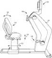
- FIG. 1is a perspective view of a recumbent therapeutic and exercise device, according to an exemplary embodiment.
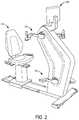
- FIG. 2is another perspective view of the recumbent therapeutic and exercise device of FIG. 1 but shown in a model image as compared to the line drawing in FIG. 1 , according to an exemplary embodiment.
- FIG. 3is a side view of the recumbent therapeutic and exercise device of FIG. 2 , according to an exemplary embodiment.
- FIGS. 4-6are perspective ( FIG. 4 ), front ( FIG. 5 ), and top ( FIG. 6 ) views of the chair of the recumbent therapeutic and exercise device of FIG. 2 , according to an exemplary embodiment.
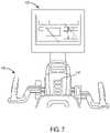
- FIG. 7is a close-up view of the display device and hand crank system of the recumbent therapeutic and exercise device of FIG. 2 , according to an exemplary embodiment.
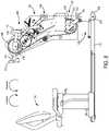
- FIG. 8is a side view of the recumbent therapeutic and exercise device of FIG. 2 with the housing removed to depict the motor and other internal components of the recumbent therapeutic and exercise device, according to an exemplary embodiment.
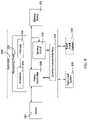
- FIG. 9is a schematic block diagram of a controller which may be used with the recumbent therapeutic and exercise device of FIGS. 1-8 , according to an exemplary embodiment.
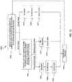
- FIG. 10is a flow diagram of a process for operating the recumbent therapeutic and exercise device of FIGS. 1-8 , according to an exemplary embodiment.
- the motorized recumbent therapeutic and exercise deviceincludes a housing that shields or covers a frame, a foot crank system coupled to the frame, a hand crank system positioned vertically above the foot crank system and coupled to the frame, a display device configured to (among other functions) output data/information regarding operation of the recumbent therapeutic and exercise device, a chair movable fore and aft relative to the housing, and a motor coupled to the frame and each of the hand crank system and the foot crank system.
- the motoris operable in an active mode of operation and in a passive mode of operation.
- the motorprovides either i) a motive or driving force to each of the hand crank system and the foot crank system to propel, force, urge, or otherwise drive each of the hand cranks and foot cranks or ii) a resistive or braking force to each of the foot cranks and the hand cranks.
- the usermust either keep up with the driving force (a powering sub-mode of the active mode of operation) or overcome the resistive force (a resistance sub-mode of the active mode of operation).
- This active mode of operationmay be beneficial to a user who desires an exercise-type of workout, where strength training and/or cardiovascular benefit is desired.
- the motorhelps or assists in the rotating or moving of the hand and foot cranks.
- the passive mode of operationmay be used for therapeutic uses (e.g., to provide a specified therapeutic program to the user), where the user desires rehabilitating one or more joints/limbs and needs some assistance in rehabilitating these joints or limbs.
- the motordoes the work to move the limbs of the user to provide the therapeutic benefit to the user.
- the device 100generally includes a housing 101 , a base 102 at least partially supporting and extending away from the housing 101 , a chair 110 moveably coupled to the base 102 , a display device 125 , a foot crank system 130 , and a hand crank system 140 .
- the useroperates the foot cranks of the foot crank system 130 in a circular or bicycle motion with their lower body (e.g., legs and feet).
- the usermay operate the hand cranks of the hand crank system 140 in a similar circular motion with their upper body (e.g., hands and arms).
- the usermay simultaneously rehabilitate or exercise their upper body (e.g., joints and muscles in their upper body including shoulders, rotator cuffs, arms in general, etc.) and their lower body (e.g., joints and muscles in their lower body including legs, feet, hip flexors, etc.) while also aerobically exercising using the device 100 .
- their upper bodye.g., joints and muscles in their upper body including shoulders, rotator cuffs, arms in general, etc.
- their lower bodye.g., joints and muscles in their lower body including legs, feet, hip flexors, etc.
- the user's abdomen and backmay also be engaged to hold themselves in the correct position (e.g., able to operate at least one of the hand crank and foot crank systems), which provides additional exercise and therapeutic or rehabilitation benefit to the user.
- the housing 101forms an enclosure to at least partially house, shield, or cover the foot crank system 130 , the hand crank system 140 , and various internal components of the device 100 such as the motor 160 (see FIG. 8 ).
- the housing 101may be constructed from one component (i.e., be of unitary or integral construction) or constructed from several components.
- the housing 101is substantially v-shaped, except that the upper portion of the “v” (i.e., the portion comprising the hand crank system 140 ) is longer than the corresponding lower power of the “v” (i.e., the portion comprising the foot crank system 130 ).
- the hand crank system 140is not only vertically offset, but horizontally offset relative to the foot crank system 130 (i.e., the hand crank system 140 is positioned closer to the chair 110 than the foot crank system 130 ).
- different shapes, curvatures, and relative lengthsmay be employed with the housing 101 to provide different relative positions between the foot crank system 140 and the hand crank system 130 .
- the housing 101may be constructed from any material.
- the housing 101is constructed from metal and/or metal alloys.
- the housing 101is constructed from plastic and/or rubber materials in order to decrease weight.
- the housing 101is constructed from a combination of metal, plastic, rubber, and/or any other materials.
- the base 102is coupled to the housing 101 and the chair 110 .
- the base 102is structured to at least partially support each of the housing 101 and the chair 110 on a support surface for the device 100 (e.g., a ground surface).
- the base 102is shown to include a front bar 103 coupled to a pair of wheels 104 (e.g., rollers, casters, etc.), a rear handle 105 positioned longitudinally opposite the front bar 103 , and plurality of longitudinally disposed holes 106 (e.g., apertures, voids, openings, etc.).
- “front”designates proximity to the housing 101 while “rear” designates a distal position from the housing 101 .
- the front bar 103extends substantially perpendicularly to the housing 101 .
- a relatively larger footprint or occupied area of the base 102is achieved for the device 100 via the front bar 103 .
- the pair of wheels 104are coupled to the front bar 103 in such a manner that they are spaced apart from a support surface for the device 100 when the device 100 is in a position for use (i.e., where a user may use the hand cranks and/or foot cranks).
- the usermay grab the rear handle 105 to lift/raise the rear portion of the device 100 to place the wheels 104 in contact with a support surface, at which point the user may push or pull the device 100 via the handle 105 to move the device 100 into a desired position.
- the base 102may be constructed from one component (i.e., be of unitary or integral construction) or constructed from several components. Additionally, the base 102 may be constructed from any material. In one embodiment, the base 102 is constructed from metal and/or metal alloys. In another embodiment, the base 102 is constructed from plastic and/or rubber materials in order to decrease weight. In still another embodiment, the base 102 is constructed from a combination of metal, plastic, rubber, and/or any other materials. Those of ordinary skill in the art will immediately recognize the wide range of the materials that may be used for the construction of the base 102 , with all such materials intended to fall within the spirit and scope of the present disclosure.
- the chair 110(e.g., user support, user support structure, or user support device) is movably coupled to the base 102 and configured to receive a user of the device 100 .
- the chair 110is shown to include a back rest 111 , a seat 112 , handlebars 113 adjacent the seat 112 , a support member 114 projecting downward from the seat 113 , a lever 115 configured to adjust a vertical height of the chair 100 (i.e., the height or distance between the seat 112 and the base 102 ), another lever 116 , and wheels 117 coupled to a pair of blocks 118 .
- each block 118is coupled to the support member 114 and is disposed on opposite sides of the base 102 .
- the support member 114is shown as a generally rectangular column coupled to the seat 112 and back rest 111 .
- the support member 114may be of other configurations, such as a generally circular column. Coupling may be via any type of fastener (e.g., bolts, etc.) or bonding technique.
- one or more of the components of the chair 110may be of unitary construction.
- the back rest 111 and seat 112may include any type of cushioning to increase the comfort of the user.
- the shape of the back rest 111 and seat 112is highly configurable with all such variations intended to fall within the scope of the present disclosure (e.g., a tear drop shaped back rest, a square seat, a “w” shaped seat, etc.).
- the chair 110includes mechanisms to adjust the vertical height of the chair 110 (i.e., the distance between the seat 112 to the base 102 ), and the relative position of the chair 110 to the housing 110 .
- the back rest 111may be angularly adjustable as well, such that, in this embodiment, the chair 110 include three degrees of freedom of movement, which are shown as reference numbers 119 (vertical height adjustment of the chair 110 ), 120 (angular adjustment of the back rest 111 ), and 121 (horizontal adjustment of the chair 110 relative to the housing 101 )(see FIG. 3 ).
- the lever 115may be actuated, moved, or otherwise controlled by a user to selectively adjust the height of the chair 110 .
- the lever 115may actuate/move a pin into and out of a hole, such that a user may lift or pull the seat 112 upward (away from the base 102 ) and once a desired height is reached, the user may move the lever 115 to insert a pin or other projecting member into an aperture or hole.
- the chair 110includes a telescoping aspect whereby an inner structure moves relative to an outer structure (i.e., the support member 114 ). This represents a manually-actuated vertical adjustment mechanism.
- a gas-spring mechanismis utilized.
- the gas-spring(not shown) is located within the support member 114 and selectively applies a force to the seat 112 to move the seat 112 and back rest 113 relative to the support member 114 in a vertical direction.
- the usermoves or actuates the lever 115 to controllably inflate/deflate the gas-spring to adjust the height of the chair 110 .
- any type of vertical adjustment mechanismmay be used.
- the chair 110is shown to include wheels 117 that engage with the base 102 to permit a rolling movement of the chair 110 relative to the base 102 and a fore and aft movement relative to the housing 101 .
- each block of the blocks 118substantially overlaps a side of the base 102 , such that the wheels 117 coupled to each block 118 engage with a channel or other surface of the base 102 .
- the wheels 117may roll upon the surface of the base 102 to enable the chair 110 to roll or move closer to or further from the housing 101 .
- the base 102defines a plurality of holes 106 (e.g., apertures, voids, openings, etc.) positioned in various positions longitudinally across a top surface of the base 102 .
- the plurality of apertures 106function as half a chair retaining mechanism for the chair 110 .
- the other half of the chair retaining mechanismis disposed on the chair 110 as a retainer (e.g., releasable bolt, pin, etc.).
- the retainermay be spring-loaded and be at least partially received in one of the plurality of apertures 106 after the chair 106 is positioned in its desired horizontal position relative to the housing 101 .
- a usermay control the lever 116 to actuate the retainer of the chair 110 into and out of an aperture in the plurality of apertures 106 .
- the userreleases or engages the retainer via actuation of the lever 116 with one of the apertures 106 to secure or lock the chair 110 in a desired position relative to the housing 101 .
- the relative positioning of the chair 110 to the housing 101may be adjusted to selectively vary the length between a user and each of the foot crank system 130 and the hand crank system 140 to, in turn, accommodate users of various sizes (e.g., heights).
- the horizontal movement mechanism of the chair 110is described herein as wheels that engage with a support surface of the base, this mechanism is not meant to be limiting as a variety of other mechanisms may also be used with all such variations intended to fall within the scope of the present disclosure (e.g., the blocks may be simply received in corresponding channels of the base and slide therein, etc.).
- the aforementioned description of the movement capabilities of the chair 110is not meant to be limiting.
- the seat 112 and back rest 111 of the chair 110may swivel or rotate relative to the support member 114 . Rotational control of the seat and back rest may be achieved by a lever or another control mechanism provided with the chair.
- a lever or another control mechanismprovided with the chair.
- FIGS. 1-7show a display device 125 adapted to display performance data relating to operation of the device 100 according to an exemplary embodiment.
- the display device 125may include any type of display device including, but not limited to, a touchscreen display device, physical input devices in combination with the display screen, and so on.
- the data outputted by the display device 125may include, but are not limited to, speed, time, distance, calories burned, heart rate, etc.
- power metersmay be included with the hand cranks and/or foot cranks for a user to track their generated power, via the display device 125 .
- the display device 125may include an integrated power source (e.g., a battery), or be electrically coupleable to an external power source (e.g., via an electrical cord that may be plugged into a wall outlet).
- the device 100is shown to include a connection panel 126 (e.g., port panel, etc.) configured to enable the electrical coupling of the device 100 to an external power source as well as to potentially other items, such as a cable television line.
- the external power sourceprovides electrical power to various electronic components on the device, such as the display device 125 and the motor 160 .
- the connection panel 126may have any combination of ports, jacks, power receptacles and the like, which may include, but are not limited to, an AV port, a HDMI input, a USB input, a coaxial cable input, etc.
- the display device 125may also include one or more input jacks (e.g., a USB input, ear plugs/headphones, an HDMI input, etc.) that receive an electronic device of the user (e.g., mobile phone, etc.) such that the display device 125 may broadcast media content from that electronic device of the user.
- the one or more input jacksmay also enable bi-directional communication, such that a user may download their workout or exercise summary to their electronic device for tracking purposes.
- other displays, cup holders, cargo nets, heart rate grips, arm exercisers, TV mounting devices, user worktops, and/or other devicesmay be incorporated into the device 100 .
- heart rate gripsmay be disposed on one or both hand cranks of the hand crank system 140 , or on the handlebars 113 , or in another location whereby the heart rate grips are configured to acquire data indicative of a heart rate of a user.
- the display device 125is coupled to the housing 101 and disposed vertically above the hand crank system 140 .
- the display device 125may be positioned in a variety of other positions, such that this positioning is not meant to be limiting (e.g., in the approximate middle of the hand crank system 140 on the housing 101 , on a side of the housing 101 , etc.).
- the device 100includes a control panel 127 .
- the control panel 127is one or more buttons, levers, switches, and the like that enable a user to control various aspects of the device 100 .
- circuitrymay couple the control panel 127 to, e.g., a motor controller 208 of the motor 160 to control activation/deactivation of the active and passive modes of operation.
- circuitrymay couple the control panel 127 to the display device 125 for turning or powering on (or off) the display device 125 and the device 100 in general (e.g., the motor controller 208 , the motor 160 , etc.).
- a quick start buttonmay be provided in the control panel 127 that enables to start using the device 100 immediately without having to, e.g., select a workout or therapeutic routine.
- user control featuresmay be disposed on the display device 125 itself (e.g., as touchscreen features or buttons disposed near the screen) as well as in other positions on the device 100 , such as on the housing 101 like the control panel 127 .
- control panel 127is not meant to be limiting as other control features may be positioned in various other positions with all such locations intended to fall within the scope of the present disclosure (e.g., on the handlebars of the chair 110 , excluded from the device 100 such that all the control features on the display device 125 , on the side of the housing 101 , etc.).
- the hand crank and foot crank systems 130 and 140are structured to enable a user to engage in therapeutic and/or exercise activity with the device 100 .
- the vertical and horizontal positions of the hand crank system 140 and the foot crank system 130are stationary or fixed relative to the housing 101 .
- the useradjusts the vertical and horizontal positioning of the chair 110 relative to the housing 101 to achieve a comfortable position with respect to the foot crank system 130 and the hand crank system 140 .
- one or both of the foot crank system 130 and the hand crank system 140may be movable relative to the housing 101 to further help achieve a comfortable position for the user for the device 100 .
- the device 100includes a frame 150 , a motor 160 , and a transmission 170 .
- the hand crank system 140 and foot crank system 130are firstly described in more detail.
- the foot crank system 130(also referred to as the foot crank assembly) is coupled to the frame 150 and generally includes a pair of foot pedals 131 coupled to a pair of arms 132 (pedal arms) (where one arm is coupled to one pedal), a shaft 133 coupled to each arm in the pair of arms 132 , and a pulley 134 .
- the shaft 133e.g., rod, axle, pedal shaft etc.
- the pulley 134e.g., gear, pedal pulley, etc.
- each pedal 131 and arm 132 combinationmay be referred to as a “foot crank” due to this combination representing a crank or moment arm on the shaft 133 .
- Each foot crankmay move or rotate about a center axis of the shaft 133 . Rotation of the foot cranks causes rotational movement of the shaft 133 .
- each pedal 131may move or rotate relative to each arm 132 ; in other alternative embodiments, the pedals 131 may be fixed relative to the arms 132 .
- Each pedal 131is adapted to receive a foot of the user.
- each pedal 131may also include any number and type of adjustment mechanisms for securely or relatively securely holding each foot, such as a strap(s), clip(s), etc. Beneficially, the use of adjustment mechanisms may enable the pedals 131 to accommodate a wide variety of foot sizes of users.
- the hand crank system 140(also referred to as the hand cranks assembly) is coupled to the frame 150 and generally includes a pair of hand grips 141 coupled to a pair of arms 142 (crank arms) (where one arm is coupled to one grip), a shaft 143 coupled to each arm in the pair of arms 142 , and a pulley 144 .
- the shaft 143e.g., rod, axle, crank shaft, etc.
- the pulley 144e.g., gear, etc.
- each grip 141 and arm 142 combinationmay be referred to as a “hand crank” due to this combination representing a crank or moment arm for the shaft 143 .
- Each hand crankmay move or rotate about a center axis of the shaft 143 . Rotation of the hand cranks causes rotational movement of the shaft 143 .
- each grip 141may move or rotate relative to each arm 142 ; in other alternative embodiments, the grips 141 may be fixed relative to the arms 142 .
- Each grip 141is adapted to receive a hand of the user (i.e., for the user to hold/grab) and move relative to each respective arm 142 .
- each grip 141may include any number and type of adjustment mechanisms for securely or relatively securely holding each hand, such as a strap(s).
- a variety of materialsmay be use with the grips 141 to facilitate a more comfortable engagement point for the user (e.g., a rubberized grip, etc.).
- the use of adjustment mechanismsmay enable the grips 141 to accommodate a wide variety of hand sizes of users.
- a usermay adjust the height of the chair 110 and the distance of the chair 110 to the housing 101 to accommodate his/her size.
- the usermay sit upon the seat 112 , grip each of the grips 141 with each of their hands, and place each of their feet on or in each of the pedals 131 .
- the usermay then simultaneously rotate the foot and hand cranks. Rotation of the foot and hand cranks may provide an aerobic exercise and help to strengthen various upper body and lower body muscles.
- the usermay desire to only work out their arms or their legs. At which point, he or she may only actuate, rotate, or otherwise move one of the foot cranks and hand cranks.
- the usermay position the chair an extended distance away from the housing 101 and use the device 100 without sitting on the chair 110 (e.g., from a standing position to actuate the hand cranks).
- the frame 150is coupled to the base 102 , the foot crank system 130 , the hand crank system 140 , and the motor 160 .
- the frame 150is an assembly of components that serve as a support structure, at least in part, for each of the foot crank system 130 , hand crank system 140 , and the motor 160 .
- the frame 150may be a unitary or one-piece component.
- the frame 150may be constructed from any suitable material including, but not limited, metal, metal alloys, plastics, rubbers, any combination thereof, and the like.
- the transmission 170is structured to couple the motor 160 to each of the hand crank system 140 and the foot crank system 130 .
- the transmission 170couples the hand crank system 140 to the foot crank system 130 , such that when a user operates the hand cranks, the foot cranks rotate in the same direction. For example, if the user rotates the hand cranks in the forward direction, the foot cranks are driven in the forward direction. The vice versa is also true: if the user operates or drives the foot cranks in, e.g., the forward direction, the hand cranks rotate in the forward direction.
- the transmission 170rotatably couples the hand cranks to the foot cranks, such that the hand cranks and foot cranks rotate in the same direction/in unison.
- the transmission 170is also structured to enable the hand cranks and foot cranks to rotate at the same or substantially the same rotational speed.
- the transmission 170enables the hand cranks and foot cranks to rotate in unison and at approximately or substantially the same rotational speed.
- various speed differential mechanismsmay be implemented with the transmission 170 to enable different relative rotational speeds between the hand cranks and the foot cranks.
- the pulley 134is larger than the pulley 144 such that the pulley 144 (and, in turn, the hand cranks 144 ) has a higher rotational speed than the pulley 134 and the foot cranks.
- the pulley 144is larger than the pulley 134 such that the hand cranks have a slower rotational speed than the foot cranks. It should be understood that in other embodiments, various other and different differential speed mechanisms may be implemented with the device 100 with all such variations intended to fall within the scope of the present disclosure.
- the transmission 170is shown to include a variety of belts, shaft assemblies having one or more pulleys and bearings (e.g., regular bearings, one-way bearings, etc.), springs, and tension assemblies. It should be understood that this depiction is not meant to be limiting as the transmission 170 may also include, in place of or in addition to the aforementioned elements, various gears, chains, etc.
- the beltsmay include any type of belt including, but not limited to, toothed belts, v-shaped belts, substantially smooth belts, etc.
- the pulleysmay have a corresponding shape to each of the belts, such that pulleys may include, but are not limited to, a v-shaped pulley, toothed pulley, etc.
- Tension assembliesmay be coupled to the frame 150 and structured to apply a tension to the belts.
- the tensionersmay be movable to provide an adjustable amount of tension to one or more belts.
- a single belti.e., the coupling belt
- this single beltenables the pulleys 134 , 144 to rotate in the same direction.
- the motor 160engages with or drives another belt (i.e., the power transfer belt).
- the power transfer beltis rotatably coupled, via one or more pulleys and belts, to the coupling belt to, in turn, transfer power or motive force from the motor 160 to the coupling belt and therefore to each of the hand crank system 140 and the foot crank system 130 .
- the motor 160is coupled to the frame 150 , and is structured to selectively i) power, drive, move, or otherwise impart a force onto each of the hand crank system 140 and the foot crank system 130 in order to drive, power, and/or otherwise rotate each of the hand cranks and the foot cranks, and ii) provide a resistive or braking force to the movement of each of the hand cranks and foot cranks in accordance with each of the active and passive modes of operation.
- the motor 160is coupled to the frame 150 , such that the frame 150 may support or at least partially support the motor 160 while the housing 101 covers or shields the motor 160 .
- the motor 160is disposed vertically closer to the foot crank system 130 than to the hand crank system 140 .
- the motor 160may be disposed in any position in the device 100 .
- the motor 160may be structured as any type of motor that may be used to selectively power (e.g., impart force) to the foot crank system 130 and the hand crank system 140 .
- the motor 160may be an alternating current (AC) motor or a direct current (DC) motor and be of any power rating desired.
- the motor 160is structured as brushless DC motor in order to be able to selectively provide a driving force which is useable in the active mode and a holding torque, which is useable in the various modes of operation, which are described in more detail herein below.
- the motor 160may be solely a motor or be a motor/generator combination unit (i.e., capable of generating electricity).
- the motor 160may receive electrical power from an external source (e.g., from a wall outlet) or from a power source integrated into the device 100 , such as a battery.
- the connection panel 126includes an outlet/receptacle for electrically coupling to an external power source, such as a wall outlet.
- the wall outlettransfers electrical power to the connection panel 126 , which transfers electrical power to various electronic components in/on the device 100 , such as the motor 160 .
- various electronic filtering componentssuch as filters, inverters, transformers, relays, and other circuitry components, may be implemented with the device 100 to enable the correct or substantially the correct amount of power being delivered to each specific component.
- one or more electrical components in/on the device 100may include an integrated power source (e.g., a capacitor, a battery, etc.), such that those components may be powered independent of the power from the external power source.
- an integrated power sourcee.g., a capacitor, a battery, etc.
- the motor 160may have a variety of specifications particular to a DC motor including, but not limited to, the no load speed, the power rating (i.e., the power output capability of the motor), the stall torque (i.e., the maximum torque that the motor can provide with the output shaft of motor not rotating), the holding torque, the torque output capability (e.g., how much torque is capable of being provided at various speeds), the stall current, etc.
- the power ratingi.e., the power output capability of the motor
- the stall torquei.e., the maximum torque that the motor can provide with the output shaft of motor not rotating
- the holding torquee.g., how much torque is capable of being provided at various speeds
- the torque output capabilitye.g., how much torque is capable of being provided at various speeds
- the stall currente.g., how much torque is capable of being provided at various speeds
- modifying the power rating and the torque output capabilitymay affect the capabilities of the active mode of operation. For example, a motor with a greater torque output
- a usermay be provided with more resistance options with this motor than with a motor with a lower torque output rating
- increasing the power ratingmay result in the motor being able to achieve relatively higher rotational speeds of the hand cranks and foot cranks as compared to a motor with a lower power rating.
- the innovations of the present disclosuremay be implemented in various models of the device 100 , such as an economy model and a performance model.
- the performance modelmay include a relatively greater power rating and torque output rating motor as compared to the economy model.
- the motor 160may also include a motor controller 208 .
- a control system 200also referred to as controller 200
- the controller 200includes a processing circuit 202 having a processor 204 and a memory 206 , a motor controller 208 , a sensing circuit 210 , and a communications interface 212 .
- Processor 204may be implemented as one or more general-purpose processors, an application specific integrated circuit (ASIC), one or more field programmable gate arrays (FPGAs), a digital signal processor (DSP), a group of processing components, or other suitable electronic processing components.
- ASICapplication specific integrated circuit
- FPGAsfield programmable gate arrays
- DSPdigital signal processor
- Processor 204is configured to execute computer code or instructions stored in memory 206 or received from other computer readable media (e.g., CDROM, network storage, a remote server, etc.).
- Memory 206e.g., NVRAM, RAM, ROM, Flash Memory, hard disk storage, etc.
- Memory 206may store data and/or computer code for facilitating at least some of the various processes described herein.
- Memory 206may include one or more devices (e.g. memory units, memory devices, storage device, etc.) for storing data and/or computer code and/or facilitating at least some of the various processes described in the present disclosure.
- the memory 206may include tangible, non-transient computer-readable medium.
- Memory 206may be communicably connected to processor 204 via processing circuit 202 and may include computer code for executing (e.g., by processor 204 ) one or more processes described herein. When processor 204 executes instructions stored in memory 206 , processor 206 generally configures controller 200 to complete such activities.
- Motor controller 208can be configured to control operation of motor 160 .
- the control signals provided to motor 160can cause motor 160 to activate, deactivate, or achieve a variable capacity or speed or torque of the motor 160 .
- Motor controller 208may be operatively and communicably coupled to a user control feature (e.g., the display device 125 and/or the control panel 127 ) to enable the user to control various aspects of the motor 160 .
- Motor 160is coupled to foot crank system 130 and hand crank system 140 to cause rotation or resistance to one or both.
- Display device 125may be used to select a program stored in memory 206 , which instructs motor 160 to operate at pre-programmed conditions via motor controller 208 .
- the communications interface 212may include any combination of wired or wireless interfaces (e.g. jacks, antennas, transmitters, receivers, transceivers, wire terminals, etc.) for conducting data communications with various system, devices, or networks.
- communications interface 212may include an Ethernet card and port for sending and receiving data via an Ethernet-based communications network and/or a Wi-Fi transceiver for communication with the plurality sensors located in foot crank system 130 and hand crank system 140 .
- the communications interface 212may facilitate and enable the communicable coupling of the motor controller 208 with the motor 160 and the sensing circuit 210 with the input/output devices of the device 100 .
- the communications interface 212may enable the coupling of the device 100 with a remote controller or operator, such that workout or therapeutic routines can be received remotely (e.g., at a distance or away) from the device 100 .
- the sensing circuit 210is structured to receive signals, information, data, or values (e.g., patient data such as heart rate) regarding operation of the device.
- sensing circuit 210may receive data from the plurality of sensors located within foot crank system 130 and hand crank system 140 . The data may be received in real time or near real time.
- the sensing circuit 210is coupled to display device 125 such that the received data from the foot crank system 130 and hand crank system 140 may be displayed via display device 125 in real time or near real time.
- the sensing circuit 210may be structured to perform various operations on the data. For example, the data acquired via the heart rate sensor(s) may be transformed by the sensing circuit 210 to show a trend for the user of the device.
- the sensing circuit 210may include one or more algorithms, processes, formulas, and the like that facilitate and enable transformation of the data to various desired output, which may be provided to the display device for display to the user of the device 100 .
- the motor controller 208 and sensing circuit 210are a part of the control system 200 .
- the motor controller and/or sensing circuit 210may be separate, discrete components relative to each other and the control system 200 .
- at least one of the motor controller 208 and sensing circuit 210may be positioned in different locations within the device 100 .
- the structures of the motor controller 208 and sensing circuit 210are highly configurable.
- one or both of the sensing circuit 210 and motor controller 208are discrete processing components (e.g., each includes one or more of various processing components (e.g., processing and memory components, whereby the processor and memory may have the same or similar configuration as described above with respect to the memory 206 and processor 204 )), and may be structured as described above, such as one or more e.g., a microcontroller(s), integrated circuit(s), system(s) on a chip, etc.
- one or more both of the sensing circuit 210 and motor controller 208may be structured as machine-readable media (e.g., non-transient computer readable medium that stores instructions that are executable by a processor or processors to perform at least some of the processes herein) that may be stored in the memory 206 and executable by the processor.
- machine-readable mediae.g., non-transient computer readable medium that stores instructions that are executable by a processor or processors to perform at least some of the processes herein
- the motor controller 208is structured as a discrete processing component (described above) while the sensing circuit 210 is structured as machine-readable media.
- this exemplary configurationis not meant to be limiting.
- FIG. 8depicts a forward rotational direction and a reverse rotational direction, which correspond respectively with a clockwise rotational direction and a counterclockwise rotational direction based on the right side view of the device 100 in FIG. 8 .
- the motor 160is operable in an active operation mode and in a passive operation mode, whereby each of mode of operation is described more fully below.
- a user inputis received regarding whether to initiate an active or passive mode of operation for the device 100 .
- User inputmay be received via display device 125 .
- the active mode of operationincludes a powering sub-mode and a resistance sub-mode.
- a user inputis received regarding whether to initiate the powering or resistance sub-mode of operation for the device 100 .
- the motor 160drives, forces, or otherwise powers (e.g., provides a drive force to) the hand cranks and foot cranks at a sufficient speed to force the user to keep up.
- the motor 160applies a braking or a resistive force to the hand cranks and foot cranks, which forces the user to overcome this braking or resistive force in order to turn the hand cranks and foot cranks.
- the usermay provide a desired speed and at process step 1008 the user may provide a desired rotational direction of the foot pedals and hand cranks.
- the usermay utilize the display device 125 or the control panel 127 to designate that the user wants to use to engage in a workout with the hand cranks and foot cranks rotating in the forward direction and at a predefined speed (e.g., 3 miles-per-hour, 50 revolutions-per-minute, or any other nomenclature designation that is used to designate rotational speed, which may also include a scale (1-10) that can be used to represent increasing/maintaining/decreasing the rotational speed of the hand and/or foot cranks).
- a predefined speede.g., 3 miles-per-hour, 50 revolutions-per-minute, or any other nomenclature designation that is used to designate rotational speed, which may also include a scale (1-10) that can be used to represent increasing/maintaining/decreasing the rotational speed of the hand and/or
- the display device 125may indicate that the workout will be in X seconds and for the user to engage with the hand cranks and foot pedals.
- the motor 160begins driving or rotating the hand cranks and foot cranks in the forward direction at the designated speed.
- the usermoves their arms and legs to keep up with the rotating hand cranks and foot cranks.
- this movementmay provide a cardiovascular exercise.
- the usermay remove their feet from the foot pedals and their hands from the hand grips and provide a command (e.g., via the display device 125 or control panel 127 ) to indicate that the user wants the motor 160 drive the hand cranks and the foot pedals in the reverse direction.
- the useralso designates a desired speed.
- the motor 160begins driving, powering, or otherwise rotating the hand cranks and foot pedals in the reverse direction.
- the device 100may be programmed with a variety of exercise, therapeutic, and workout programs, which direct or command the motor 160 to operate at different speeds and different directions for certain periods of time. In either configuration (a programmed workout or a manual operating mode for prescribing the direction and speed), the user may receive a cardiovascular benefit while still being friendly/easy on joints/limbs of a user.
- datamay be acquired using sensors (actual or virtual—i.e., a not physical sensor where data, values, or information are determined based on various inputs from actual sensors and/or various estimates, guestimates, predictions, etc.) coupled to the foot crank system 130 , hand crank system 140 , and/or by motor controller 208 .
- Datamay include patient data, such as heart rate, or data regarding the foot crank system 130 and hand crank system 140 , such as number of rotations.
- the usermay utilize the display device 125 or the control panel 127 to stop the current workout program. Additionally, the workout program may have a set time period, and upon complete of the time period the workout program will stop.
- another operation sub-mode of the active mode of operation of the motor 160is to designate a force (e.g., torque, resistance, braking force, etc.) that the motor 160 applies to the foot crank and hand cranks as well as a desired not-to-exceed rotational speed (i.e., a threshold speed) and a rotational direction.
- the not-to-exceed rotational speedrepresents the rotational speed of the foot cranks and the hand cranks that the user attempts to keep the foot cranks and hand cranks at or under.
- the userresists/is actively fighting against the designated force and speed in order to keep the rotational speed of the foot cranks and hand cranks at a rotational speed that is less than or equal to (i.e., slower) the not-to-exceed rotational speed.
- the useris actively working to keep the rotation of the hand cranks and foot cranks slower than a designated speed whereas, in comparison to the resistance sub-mode described below, the user there is fighting against the resistance to keep the hand cranks and foot cranks moving.
- This motor 160 mode of operationmay be beneficial to users looking to strength train various muscle stabilizers of their upper and lower body, as well as gain an aerobic benefit.
- the usermay indicate that the resistance sub-mode is desired.
- the usermay provide a desired resistance level.
- the motor controller 208may convert the desired resistance level (e.g., 1, 2, 3, 4, . . . etc.), to a torque output of the motor 160 .
- the desired resistance levele.g., 1, 2, 3, 4, . . . etc.
- the usermust overcome the torque output (i.e., resistive force) of the motor 160 to enable rotation of the hand cranks and foot pedals.
- the usermay freely switch between a forward rotational direction and a reverse rotational direction during the resistance mode as the output shaft of the motor 160 may remain substantially stationary.
- the userwill have to overcome the torque output in either the forward rotational direction or the reverse rotational direction in order to enable the rotation of the foot cranks and hand cranks.
- the described configuration aboverelates to a holding torque implementation where the motor output shaft is stationary.
- the motor 160may still power, rotate, or drive the hand cranks and foot cranks despite a torque being applied to the hand cranks and foot cranks.
- the motor 160may output a certain output shaft speed. The user will operate the hand cranks and foot cranks in the same direction as that of the motor 160 , but will have to exceed the torque output if the user desires a faster rotational speed at the torque output.
- the resistance mode of operationmay be used to replicate the user traversing hills on the bike portion of the device 100 or to simulate other more difficult environmental encounters (e.g., a rough terrain).
- the resistance mode of operationmay be desirable for users wanting to strength train in addition to performing a cardiovascular exercise. In this regard, muscle contraction and expansion may be relatively greater during the resistance sub-mode than during the powering sub-mode.
- datamay be acquired using sensors (virtual or physical/actual) coupled to the foot crank system 130 , hand crank system 140 , and/or by motor controller 208 .
- Datamay include patient data, such as heart rate, or data regarding the foot crank system 130 and hand crank system 140 , such as number of rotations.
- the usermay utilize the display device 125 or the control panel 127 to stop the current workout program. Additionally, the workout program may have a set time period, and upon complete of the time period the workout program will stop.
- the usermay select the passive mode of operation.
- the motor 160is operable to drive or power the hand cranks and foot cranks at a desired speed and in a desired direction.
- the usermay provide a desired speed and at process step 1020 the user may provide a desired direction of rotation. While this high level description seems similar to the active mode of operation, the passive mode of operation is intended for therapeutic uses. In this regard, rather than the user “actively” working to keep up with rotating foot cranks and hand cranks in the powering sub-mode of the active mode or working to overcome the resistance in the resistance mode of the active mode, here, the user is “passively” receiving a therapeutic benefit from, primarily, operation of the device 100 and motor 160 .
- the useris passive in that the device 100 is causing movement of the user (i.e., driving the user's arm in a circular motion or driving the user's legs in a circular motion).
- the passive mode of operationmay also be referred to as the therapeutic mode of operation herein.
- the usermay desire to stretch out their shoulder to, e.g., increase their mobility because the user has a difficult time doing arm circles.
- the usermay, via the display device 125 or the control panel 127 , indicate that they desire a therapeutic operating mode (i.e., the passive mode) and either designate a speed and direction of the foot and hand cranks or (if provided) utilize a predefined speed and direction of the foot and hand cranks.
- the device 100may be preprogrammed with a (or multiple) therapeutic workouts/routines that automatically or nearly automatically run once the passive mode of operation is selected, eliminating the need for process steps 1018 and 1020 .
- the usermay grip the hand grips 141 that are then rotated at the therapeutic speed, which is typically much slower than in the powering sub-mode.
- the motor 160indirectly causes the user's shoulder's to be moved while the user simply holds onto the grips 141 .
- the foot cranksThe user may place their feet in the foot pedals 131 , which are driven at a therapeutic pace (typically much slower than in the active mode) to stretch out their legs (e.g., joints and limbs, such as the knee).
- the usermay perform a simultaneous therapeutic exercise by gripping the hand grips 141 and placing their feet in/on the foot pedals 131 .
- datamay be acquired using sensors coupled to the foot crank system 130 , hand crank system 140 , and/or by motor controller 208 .
- Datamay include patient data, such as heart rate, or data regarding the foot crank system 130 and hand crank system 140 , such as number of rotations.
- the usermay utilize the display device 125 or the control panel 127 to stop the current therapeutic program. Additionally, the therapeutic program may have a set time period, and upon complete of the time period the therapeutic program will stop.
- the motorized recumbent and therapeutic and exercise device 100 of the present disclosureis capable of providing exercise and therapeutic benefits to the user.
- the device 100may also be operable in a non-motorized mode of operation.
- the holding torque of the motor 160is disabled/de-energized.
- the output shaft of the motor 160freely rotates.
- the usermay move, turn, or otherwise operate the hand cranks and foot cranks in the forward or reverse directions as if no motor were present on the device 100 .
- the useronly has to overcome the frictional forces due to the transmission 170 and other components in the device 100 in order to cause the rotation of the foot cranks and hand cranks.
- users of all skill levels, capabilities, and fitness levelsmay find the device 100 of the present disclosure appealing. For example, users who wish to rehabilitate an injury can utilize the therapeutic mode of operation. Users who wish to build strength may utilize the resistance sub-mode of the active mode of operation. Users who desire a cardiovascular exercise may utilize the powering sub-mode of the active mode of operation. And, users who simply want to use the device 100 without motor 160 input may utilize the non-motorized mode of operation.
- the motor 160may be useable with only one of the foot cranks and the hand cranks.
- the hand cranksmay be unconnected or uncoupled to the motor, such that the aforementioned described modes of operation are only useable with the foot cranks.
- the foot cranksmay be unconnected or uncoupled to the motor, such that the aforementioned described modes of operation are only applicable with the hand cranks.
- a first dedicated motormay be provided as part of the hand crank system 140 while a second dedicated motor is provided as part of the foot crank system 130 .
- the usermay individually control operation of each motor to, in turn, control operation of the hand cranks and foot cranks separately.
- the term “coupled”means the joining of two members directly or indirectly to one another. Such joining may be stationary or moveable in nature. Such joining may be achieved with the two members or the two members and any additional intermediate members being integrally formed as a single unitary body with one another or with the two members or the two members and any additional intermediate members being attached to one another. Such joining may be permanent in nature or may be removable or releasable in nature.
Landscapes
- Health & Medical Sciences (AREA)
- General Health & Medical Sciences (AREA)
- Physical Education & Sports Medicine (AREA)
- Life Sciences & Earth Sciences (AREA)
- Biophysics (AREA)
- Orthopedic Medicine & Surgery (AREA)
- Rehabilitation Therapy (AREA)
- Epidemiology (AREA)
- Pain & Pain Management (AREA)
- Animal Behavior & Ethology (AREA)
- Public Health (AREA)
- Veterinary Medicine (AREA)
- Cardiology (AREA)
- Vascular Medicine (AREA)
- Physics & Mathematics (AREA)
- Electromagnetism (AREA)
- Engineering & Computer Science (AREA)
- Multimedia (AREA)
- Human Computer Interaction (AREA)
- Rehabilitation Tools (AREA)
Abstract
Description
Claims (21)
Priority Applications (1)
| Application Number | Priority Date | Filing Date | Title |
|---|---|---|---|
| US15/892,484US11298284B2 (en) | 2017-02-10 | 2018-02-09 | Motorized recumbent therapeutic and exercise device |
Applications Claiming Priority (2)
| Application Number | Priority Date | Filing Date | Title |
|---|---|---|---|
| US201762457417P | 2017-02-10 | 2017-02-10 | |
| US15/892,484US11298284B2 (en) | 2017-02-10 | 2018-02-09 | Motorized recumbent therapeutic and exercise device |
Publications (2)
| Publication Number | Publication Date |
|---|---|
| US20180228682A1 US20180228682A1 (en) | 2018-08-16 |
| US11298284B2true US11298284B2 (en) | 2022-04-12 |
Family
ID=61189318
Family Applications (1)
| Application Number | Title | Priority Date | Filing Date |
|---|---|---|---|
| US15/892,484Active2039-10-30US11298284B2 (en) | 2017-02-10 | 2018-02-09 | Motorized recumbent therapeutic and exercise device |
Country Status (2)
| Country | Link |
|---|---|
| US (1) | US11298284B2 (en) |
| EP (1) | EP3409329A1 (en) |
Cited By (50)
| Publication number | Priority date | Publication date | Assignee | Title |
|---|---|---|---|---|
| US20230019435A1 (en)* | 2019-05-08 | 2023-01-19 | Lagree Technologies, Inc. | Exercise Machine Handle System |
| US20230381568A1 (en)* | 2022-05-27 | 2023-11-30 | Kosta Tzavaras | Magnetic Resistance Spin Pod Upper Body Exercise Frame |
| US11955218B2 (en) | 2019-10-03 | 2024-04-09 | Rom Technologies, Inc. | System and method for use of telemedicine-enabled rehabilitative hardware and for encouraging rehabilitative compliance through patient-based virtual shared sessions with patient-enabled mutual encouragement across simulated social networks |
| US11955222B2 (en) | 2019-10-03 | 2024-04-09 | Rom Technologies, Inc. | System and method for determining, based on advanced metrics of actual performance of an electromechanical machine, medical procedure eligibility in order to ascertain survivability rates and measures of quality-of-life criteria |
| US11950861B2 (en) | 2019-10-03 | 2024-04-09 | Rom Technologies, Inc. | Telemedicine for orthopedic treatment |
| US11955220B2 (en) | 2019-10-03 | 2024-04-09 | Rom Technologies, Inc. | System and method for using AI/ML and telemedicine for invasive surgical treatment to determine a cardiac treatment plan that uses an electromechanical machine |
| US11955223B2 (en) | 2019-10-03 | 2024-04-09 | Rom Technologies, Inc. | System and method for using artificial intelligence and machine learning to provide an enhanced user interface presenting data pertaining to cardiac health, bariatric health, pulmonary health, and/or cardio-oncologic health for the purpose of performing preventative actions |
| US11955221B2 (en) | 2019-10-03 | 2024-04-09 | Rom Technologies, Inc. | System and method for using AI/ML to generate treatment plans to stimulate preferred angiogenesis |
| US11957956B2 (en) | 2019-05-10 | 2024-04-16 | Rehab2Fit Technologies, Inc. | System, method and apparatus for rehabilitation and exercise |
| US11961603B2 (en) | 2019-10-03 | 2024-04-16 | Rom Technologies, Inc. | System and method for using AI ML and telemedicine to perform bariatric rehabilitation via an electromechanical machine |
| US11978559B2 (en) | 2019-10-03 | 2024-05-07 | Rom Technologies, Inc. | Systems and methods for remotely-enabled identification of a user infection |
| US12020800B2 (en) | 2019-10-03 | 2024-06-25 | Rom Technologies, Inc. | System and method for using AI/ML and telemedicine to integrate rehabilitation for a plurality of comorbid conditions |
| US12020799B2 (en) | 2019-10-03 | 2024-06-25 | Rom Technologies, Inc. | Rowing machines, systems including rowing machines, and methods for using rowing machines to perform treatment plans for rehabilitation |
| US12029940B2 (en) | 2019-03-11 | 2024-07-09 | Rom Technologies, Inc. | Single sensor wearable device for monitoring joint extension and flexion |
| US12057237B2 (en) | 2020-04-23 | 2024-08-06 | Rom Technologies, Inc. | Method and system for describing and recommending optimal treatment plans in adaptive telemedical or other contexts |
| US12062425B2 (en) | 2019-10-03 | 2024-08-13 | Rom Technologies, Inc. | System and method for implementing a cardiac rehabilitation protocol by using artificial intelligence and standardized measurements |
| US12100499B2 (en) | 2020-08-06 | 2024-09-24 | Rom Technologies, Inc. | Method and system for using artificial intelligence and machine learning to create optimal treatment plans based on monetary value amount generated and/or patient outcome |
| US12096997B2 (en) | 2019-10-03 | 2024-09-24 | Rom Technologies, Inc. | Method and system for treating patients via telemedicine using sensor data from rehabilitation or exercise equipment |
| US12102878B2 (en) | 2019-05-10 | 2024-10-01 | Rehab2Fit Technologies, Inc. | Method and system for using artificial intelligence to determine a user's progress during interval training |
| US12154672B2 (en) | 2019-10-03 | 2024-11-26 | Rom Technologies, Inc. | Method and system for implementing dynamic treatment environments based on patient information |
| US12150792B2 (en) | 2019-10-03 | 2024-11-26 | Rom Technologies, Inc. | Augmented reality placement of goniometer or other sensors |
| US12165768B2 (en) | 2019-10-03 | 2024-12-10 | Rom Technologies, Inc. | Method and system for use of telemedicine-enabled rehabilitative equipment for prediction of secondary disease |
| US12176089B2 (en) | 2019-10-03 | 2024-12-24 | Rom Technologies, Inc. | System and method for using AI ML and telemedicine for cardio-oncologic rehabilitation via an electromechanical machine |
| US12183447B2 (en) | 2019-10-03 | 2024-12-31 | Rom Technologies, Inc. | Method and system for creating an immersive enhanced reality-driven exercise experience for a user |
| US12191021B2 (en) | 2019-10-03 | 2025-01-07 | Rom Technologies, Inc. | System and method for use of telemedicine-enabled rehabilitative hardware and for encouragement of rehabilitative compliance through patient-based virtual shared sessions |
| US12191018B2 (en) | 2019-10-03 | 2025-01-07 | Rom Technologies, Inc. | System and method for using artificial intelligence in telemedicine-enabled hardware to optimize rehabilitative routines capable of enabling remote rehabilitative compliance |
| US12220201B2 (en) | 2019-10-03 | 2025-02-11 | Rom Technologies, Inc. | Remote examination through augmented reality |
| US12224052B2 (en) | 2019-10-03 | 2025-02-11 | Rom Technologies, Inc. | System and method for using AI, machine learning and telemedicine for long-term care via an electromechanical machine |
| US12230382B2 (en) | 2019-10-03 | 2025-02-18 | Rom Technologies, Inc. | Systems and methods for using artificial intelligence and machine learning to predict a probability of an undesired medical event occurring during a treatment plan |
| US12230381B2 (en) | 2019-10-03 | 2025-02-18 | Rom Technologies, Inc. | System and method for an enhanced healthcare professional user interface displaying measurement information for a plurality of users |
| US12230383B2 (en) | 2019-10-03 | 2025-02-18 | Rom Technologies, Inc. | United states systems and methods for using elliptical machine to perform cardiovascular rehabilitation |
| US12226671B2 (en) | 2019-03-11 | 2025-02-18 | Rom Technologies, Inc. | System, method and apparatus for electrically actuated pedal for an exercise or rehabilitation machine |
| US12246222B2 (en) | 2019-10-03 | 2025-03-11 | Rom Technologies, Inc. | Method and system for using artificial intelligence to assign patients to cohorts and dynamically controlling a treatment apparatus based on the assignment during an adaptive telemedical session |
| US12249410B2 (en) | 2019-10-03 | 2025-03-11 | Rom Technologies, Inc. | System and method for use of treatment device to reduce pain medication dependency |
| US12283356B2 (en) | 2019-10-03 | 2025-04-22 | Rom Technologies, Inc. | System and method for processing medical claims using biometric signatures |
| US12285654B2 (en) | 2019-05-10 | 2025-04-29 | Rom Technologies, Inc. | Method and system for using artificial intelligence to interact with a user of an exercise device during an exercise session |
| US12301663B2 (en) | 2019-10-03 | 2025-05-13 | Rom Technologies, Inc. | System and method for transmitting data and ordering asynchronous data |
| US12327623B2 (en) | 2019-10-03 | 2025-06-10 | Rom Technologies, Inc. | System and method for processing medical claims |
| US12324961B2 (en) | 2019-05-10 | 2025-06-10 | Rom Technologies, Inc. | Method and system for using artificial intelligence to present a user interface representing a user's progress in various domains |
| US12340884B2 (en) | 2019-10-03 | 2025-06-24 | Rom Technologies, Inc. | Method and system to analytically optimize telehealth practice-based billing processes and revenue while enabling regulatory compliance |
| US12347543B2 (en) | 2019-10-03 | 2025-07-01 | Rom Technologies, Inc. | Systems and methods for using artificial intelligence to implement a cardio protocol via a relay-based system |
| US12347558B2 (en) | 2019-10-03 | 2025-07-01 | Rom Technologies, Inc. | Method and system for using artificial intelligence and machine learning to provide recommendations to a healthcare provider in or near real-time during a telemedicine session |
| US12357195B2 (en) | 2020-06-26 | 2025-07-15 | Rom Technologies, Inc. | System, method and apparatus for anchoring an electronic device and measuring a joint angle |
| US12380984B2 (en) | 2019-10-03 | 2025-08-05 | Rom Technologies, Inc. | Systems and methods for using artificial intelligence and machine learning to generate treatment plans having dynamically tailored cardiac protocols for users to manage a state of an electromechanical machine |
| US12390689B2 (en) | 2019-10-21 | 2025-08-19 | Rom Technologies, Inc. | Persuasive motivation for orthopedic treatment |
| US12402805B2 (en) | 2019-09-17 | 2025-09-02 | Rom Technologies, Inc. | Wearable device for coupling to a user, and measuring and monitoring user activity |
| US12424319B2 (en) | 2019-11-06 | 2025-09-23 | Rom Technologies, Inc. | System for remote treatment utilizing privacy controls |
| US12420143B1 (en) | 2019-10-03 | 2025-09-23 | Rom Technologies, Inc. | System and method for enabling residentially-based cardiac rehabilitation by using an electromechanical machine and educational content to mitigate risk factors and optimize user behavior |
| US12420145B2 (en) | 2019-10-03 | 2025-09-23 | Rom Technologies, Inc. | Systems and methods of using artificial intelligence and machine learning for generating alignment plans to align a user with an imaging sensor during a treatment session |
| US12427376B2 (en) | 2019-10-03 | 2025-09-30 | Rom Technologies, Inc. | Systems and methods for an artificial intelligence engine to optimize a peak performance |
Families Citing this family (45)
| Publication number | Priority date | Publication date | Assignee | Title |
|---|---|---|---|---|
| JP6418652B2 (en)* | 2016-04-22 | 2018-11-07 | トヨタ自動車株式会社 | Upper limb rehabilitation support apparatus and method for operating the same |
| US12053665B2 (en)* | 2017-09-18 | 2024-08-06 | D Curtis DeForest, Jr. | Human powered strengthening machine |
| DE102017122295A1 (en)* | 2017-09-26 | 2019-03-28 | Anton Reck e.K. | Device for height adjustment |
| US10722414B2 (en)* | 2017-11-01 | 2020-07-28 | Alex Bush | Exercising device |
| US10722751B2 (en)* | 2018-02-27 | 2020-07-28 | Johnson Health Tech Co., Ltd. | Exercise apparatus |
| US11324990B2 (en)* | 2018-10-22 | 2022-05-10 | Andrew F. Clark | Modular exercise apparatus, system, and methods |
| CN109568080B (en)* | 2018-11-28 | 2021-02-09 | 青岛大学附属医院 | Arm oscillating type rehabilitation training device |
| US11000726B2 (en)* | 2018-11-30 | 2021-05-11 | Heriberto Gonzalez | Portable hand cycle |
| CN109620642B (en)* | 2019-01-02 | 2021-05-07 | 江苏尚美医疗器械有限公司 | Hospital recovers rehabilitation device with fracture patient |
| DE102019200954A1 (en) | 2019-01-25 | 2020-07-30 | Sonova Ag | Signal processing device, system and method for processing audio signals |
| JP7181801B2 (en)* | 2019-01-30 | 2022-12-01 | Cyberdyne株式会社 | Cardiac rehabilitation support device and its control program |
| WO2020185769A1 (en)* | 2019-03-11 | 2020-09-17 | Rom Technologies, Inc. | System, method and apparatus for exercise or rehabilitation equipment |
| US11185735B2 (en) | 2019-03-11 | 2021-11-30 | Rom Technologies, Inc. | System, method and apparatus for adjustable pedal crank |
| US11957960B2 (en) | 2019-05-10 | 2024-04-16 | Rehab2Fit Technologies Inc. | Method and system for using artificial intelligence to adjust pedal resistance |
| US11433276B2 (en) | 2019-05-10 | 2022-09-06 | Rehab2Fit Technologies, Inc. | Method and system for using artificial intelligence to independently adjust resistance of pedals based on leg strength |
| US20200360761A1 (en)* | 2019-05-14 | 2020-11-19 | OrthoGenesys, Inc. | System, method and apparatus for cycling device having pedals with independently adjustable resistance |
| US11801419B2 (en)* | 2019-05-23 | 2023-10-31 | Rehab2Fit Technologies, Inc. | System, method and apparatus for rehabilitation and exercise with multi-configurable accessories |
| CN110074942A (en)* | 2019-05-27 | 2019-08-02 | 北京理工华汇智能科技有限公司 | Device for healing and training and rehabilitation wheelchair with Telescopic |
| CN110124266B (en)* | 2019-05-29 | 2020-12-18 | 韩江红 | Rehabilitation exercise device for elderly care |
| US11458354B2 (en)* | 2019-05-31 | 2022-10-04 | Rehab2Fit Technologies, Inc. | Modular exercise system |
| CN110327587B (en)* | 2019-07-09 | 2021-05-28 | 厦门景杉网络科技有限公司 | Method for simulating route riding of exercise bicycle and exercise bicycle system |
| CN110523059A (en)* | 2019-08-16 | 2019-12-03 | 芜湖天人智能机械有限公司 | A control circuit of a trainer and the trainer |
| CN110522606B (en)* | 2019-09-05 | 2021-08-10 | 河北工业大学 | Pedal type gait rehabilitation training device |
| US11701548B2 (en) | 2019-10-07 | 2023-07-18 | Rom Technologies, Inc. | Computer-implemented questionnaire for orthopedic treatment |
| US20210077860A1 (en)* | 2019-09-17 | 2021-03-18 | Rom Technologies, Inc. | Reactive protocols for orthopedic treatment |
| US11515028B2 (en) | 2019-10-03 | 2022-11-29 | Rom Technologies, Inc. | Method and system for using artificial intelligence and machine learning to create optimal treatment plans based on monetary value amount generated and/or patient outcome |
| US11915816B2 (en) | 2019-10-03 | 2024-02-27 | Rom Technologies, Inc. | Systems and methods of using artificial intelligence and machine learning in a telemedical environment to predict user disease states |
| US11830601B2 (en) | 2019-10-03 | 2023-11-28 | Rom Technologies, Inc. | System and method for facilitating cardiac rehabilitation among eligible users |
| US12087426B2 (en) | 2019-10-03 | 2024-09-10 | Rom Technologies, Inc. | Systems and methods for using AI ML to predict, based on data analytics or big data, an optimal number or range of rehabilitation sessions for a user |
| US11887717B2 (en) | 2019-10-03 | 2024-01-30 | Rom Technologies, Inc. | System and method for using AI, machine learning and telemedicine to perform pulmonary rehabilitation via an electromechanical machine |
| US11270795B2 (en) | 2019-10-03 | 2022-03-08 | Rom Technologies, Inc. | Method and system for enabling physician-smart virtual conference rooms for use in a telehealth context |
| US11101028B2 (en) | 2019-10-03 | 2021-08-24 | Rom Technologies, Inc. | Method and system using artificial intelligence to monitor user characteristics during a telemedicine session |
| US11756666B2 (en) | 2019-10-03 | 2023-09-12 | Rom Technologies, Inc. | Systems and methods to enable communication detection between devices and performance of a preventative action |
| US11075000B2 (en) | 2019-10-03 | 2021-07-27 | Rom Technologies, Inc. | Method and system for using virtual avatars associated with medical professionals during exercise sessions |
| US11915815B2 (en) | 2019-10-03 | 2024-02-27 | Rom Technologies, Inc. | System and method for using artificial intelligence and machine learning and generic risk factors to improve cardiovascular health such that the need for additional cardiac interventions is mitigated |
| US11923065B2 (en) | 2019-10-03 | 2024-03-05 | Rom Technologies, Inc. | Systems and methods for using artificial intelligence and machine learning to detect abnormal heart rhythms of a user performing a treatment plan with an electromechanical machine |
| US11167173B2 (en)* | 2019-12-09 | 2021-11-09 | Elly Frymire Cone | Physical therapy and fitness device: resistance band with pedals |
| CN110974619B (en)* | 2019-12-13 | 2021-09-28 | 曹杨 | Anti-falling sitting and standing dual-purpose leg traction rehabilitation device for orthopedic treatment |
| US11925834B2 (en)* | 2020-04-15 | 2024-03-12 | Tana Burke | Mobile cycling apparatus |
| US12151135B2 (en) | 2020-06-12 | 2024-11-26 | Thorux Corp. | Electric motor based physical training technology and devices |
| CN212941179U (en)* | 2020-07-21 | 2021-04-13 | 厦门帝玛斯健康科技有限公司 | Multi-angle folding and changing exercise bike |
| CN114452607A (en)* | 2020-11-10 | 2022-05-10 | 基赫科技股份有限公司 | Hand and foot cooperative exercise machine and control method thereof |
| US11577122B2 (en)* | 2021-01-19 | 2023-02-14 | Gee Hoo Fitec Corp. | Limbs cooperation exerciser and control method for the same |
| US20230381592A1 (en)* | 2022-05-26 | 2023-11-30 | Torque3, Inc. | Neurological rehabilitation system |
| TWI799307B (en)* | 2022-06-28 | 2023-04-11 | 岱宇國際股份有限公司 | Exercise equipment with rotatable display |
Citations (88)
| Publication number | Priority date | Publication date | Assignee | Title |
|---|---|---|---|---|
| US583920A (en) | 1897-06-08 | Lugie de montgomery | ||
| US1820372A (en) | 1928-02-08 | 1931-08-25 | August E R Blomquist | Exercising machine |
| US3017180A (en) | 1958-11-04 | 1962-01-16 | Aronsohn Allan | Exercising and gymnastics appliances |
| US3213852A (en) | 1963-07-29 | 1965-10-26 | Lawson J Zent | Exercising apparatus |
| US3216722A (en) | 1963-01-09 | 1965-11-09 | Earl R Odom | Exercise machine |
| US3455295A (en) | 1966-06-13 | 1969-07-15 | Kellogg S Health Products Inc | Exercising apparatus |
| US3572699A (en) | 1969-05-21 | 1971-03-30 | Harry B Nies | Bicycle exerciser with interconnected hand and foot pedals |
| US3824993A (en) | 1971-08-04 | 1974-07-23 | J Grant | Physio-therapy method and apparatus |
| US3964742A (en) | 1973-10-17 | 1976-06-22 | Guido Carnielli | Physiological active and passive exercising apparatus |
| US3991749A (en) | 1975-11-17 | 1976-11-16 | Zent Lawson J | Exercising apparatus |
| GB2096006A (en) | 1981-04-03 | 1982-10-13 | Ind Energy Specialists Inc | Exerciser for disabled persons |
| US4436097A (en) | 1982-06-07 | 1984-03-13 | Cunningham Patrick J | Cardiovascular exercise apparatus |
| US4572501A (en) | 1983-07-01 | 1986-02-25 | Claudia Durham | Exercise device for attachment to a wheelchair |
| US4577862A (en)* | 1984-01-30 | 1986-03-25 | Sagedahl Steven M | Isokinetic exercise apparatus and method |
| US4589656A (en) | 1984-11-07 | 1986-05-20 | Nautilus Sports/Medical Industries, Inc. | Aerobic exercise device for increased user comfort |
| US4592545A (en)* | 1984-01-30 | 1986-06-03 | Sagedahl Steven M | Isokinetic exercise apparatus and method |
| US4612447A (en) | 1983-09-07 | 1986-09-16 | Rowe Eugene T | Method and apparatus for converting human exercise energy to stored kinetic energy |
| US4618141A (en) | 1985-04-12 | 1986-10-21 | Ashworth Jr Thomas | Therapeutic exercise device |
| US4688791A (en) | 1985-03-25 | 1987-08-25 | Long Needham L | Swimming motion exerciser |
| US4712789A (en) | 1987-04-10 | 1987-12-15 | Schwinn Bicycle Company | Cycle exercisers |
| US4842269A (en) | 1987-12-30 | 1989-06-27 | Huang Gwo Ming | Multi-functional stationary bike for gymnastic purpose |
| US4846156A (en) | 1984-04-06 | 1989-07-11 | Kopnicky Robert J | Quadra-limbular therapeutic exercise machine |
| US4934692A (en) | 1986-04-29 | 1990-06-19 | Robert M. Greening, Jr. | Exercise apparatus providing resistance variable during operation |
| US4947836A (en) | 1987-09-21 | 1990-08-14 | Hillcrest Medical Center | Exerciser with muscle stimulation |
| US4976426A (en) | 1989-09-06 | 1990-12-11 | Garden Reach Developments Ltd. | Rehabilitation exercise device |
| US5044627A (en) | 1990-01-25 | 1991-09-03 | Huang Gwo Ming | Multi-functional stationary bike for gymnastic purpose |
| US5145479A (en) | 1991-04-03 | 1992-09-08 | Brad Olschansky | Total body exercising apparatus |
| US5242339A (en) | 1991-10-15 | 1993-09-07 | The United States Of America As Represented By The Administrator Of The National Aeronautics And Space Adminstration | Apparatus and method for measuring subject work rate on an exercise device |
| US5242179A (en) | 1991-10-11 | 1993-09-07 | Research Foundation Of The State University Of New York | Four-line exercising attachment for wheelchairs |
| US5318487A (en) | 1992-05-12 | 1994-06-07 | Life Fitness | Exercise system and method for managing physiological intensity of exercise |
| US5330402A (en) | 1993-05-11 | 1994-07-19 | Johnson Kimball W | Exercising device |
| US5336147A (en) | 1993-12-03 | 1994-08-09 | Sweeney Iii Edward C | Exercise machine |
| US5342262A (en) | 1993-09-13 | 1994-08-30 | Hansen Mark D | Vertically-disposed exercise machine |
| US5343856A (en)* | 1992-11-18 | 1994-09-06 | Proctor Alfred E | Complete body passive exercise machine |
| US5449334A (en) | 1994-03-22 | 1995-09-12 | Kingsbury; Doug | Rotatable exercise apparatus |
| US5569128A (en) | 1994-02-03 | 1996-10-29 | Icon Health & Fitness, Inc. | Leg and upper body exerciser |
| US5595557A (en) | 1995-08-21 | 1997-01-21 | Lambert, Sr.; Lloyd J. | Exercise machine with two sets of pedals |
| US5601515A (en) | 1991-07-05 | 1997-02-11 | Cat Eye Co., Ltd. | Adjustable recumbent bicycle exerciser |
| US5857943A (en) | 1996-05-29 | 1999-01-12 | Physicians' Preference, Inc. | Ergodynamically designed exercise device |
| US5906563A (en) | 1997-12-22 | 1999-05-25 | Pittari; Dominic | Dual exercise bike |
| US5980431A (en) | 1998-06-24 | 1999-11-09 | Miller, Jr.; John | Multi-cycle |
| US6036623A (en) | 1998-01-06 | 2000-03-14 | Mitchell; John R. | Collapsible machine for exercising the whole body of an exerciser in a wheelchair |
| US6135923A (en) | 1998-04-23 | 2000-10-24 | Stearns; Kenneth W. | Exercise methods and apparatus |
| US6328676B1 (en) | 1997-06-18 | 2001-12-11 | Technogym S.R.L. | Treadmill |
| US20020049122A1 (en)* | 1998-07-23 | 2002-04-25 | Fred Mercado | Exercise and therapeutic trainer |
| US20020061804A1 (en) | 2000-10-06 | 2002-05-23 | Toshiyuki Hasegawa | Functionality improving training machine |
| US6454679B1 (en) | 1998-06-09 | 2002-09-24 | Scott Brian Radow | Bipedal locomotion training and performance evaluation device and method |
| US20030092533A1 (en) | 2001-11-10 | 2003-05-15 | Hippensteel Joseph B. | Antigravity full range of motion four limb dry swim exercise machine |
| US20040097341A1 (en) | 2002-10-25 | 2004-05-20 | Technogym S.P.A. | Exercise machine |
| US20040259693A1 (en) | 2003-06-18 | 2004-12-23 | Zmi Electronics Ltd. | Cycling-type physical therapy apparatus with an electrical stimulation device |
| US6840892B1 (en) | 2002-08-22 | 2005-01-11 | Tonic Fitness Technology, Inc. | Recuperating machine |
| US6902515B2 (en) | 2003-04-04 | 2005-06-07 | Norman L. Howell | Multi-functional exercise apparatus |
| US20050143226A1 (en) | 2001-03-10 | 2005-06-30 | Steven Heidecke | Exercise device |
| US20060003871A1 (en) | 2004-04-27 | 2006-01-05 | Houghton Andrew D | Independent and separately actuated combination fitness machine |
| US20060252607A1 (en) | 2005-05-03 | 2006-11-09 | Holloway Herman E | Vertical total body exercise apparatus |
| US20080085819A1 (en) | 2006-10-05 | 2008-04-10 | Tian-Fang Yang | Multi-degree-of-freedom (MDOF) muscle training machine |
| US20080254949A1 (en) | 2005-09-26 | 2008-10-16 | Milton Rodrigues Fernandes | Equipment For Ergometric Body Exercises in Aerial Position |
| WO2009014330A1 (en) | 2007-07-20 | 2009-01-29 | Jae-Chul Kim | A weight training treadmill and its controlling method |
| US7510512B1 (en) | 2003-12-04 | 2009-03-31 | Michael Blake Taggett | Exercise machine |
| US7625318B1 (en) | 2004-06-28 | 2009-12-01 | Steven Heyn | Exercise apparatus |
| US20100222182A1 (en) | 2007-10-16 | 2010-09-02 | Dasan Rnd Co., Ltd. | Treadmill with automatic speed control and control module of the same |
| US7789808B2 (en) | 2008-07-30 | 2010-09-07 | Sunny Lee | Exercising device |
| US20100234179A1 (en) | 2007-08-22 | 2010-09-16 | Jacques Carl Cronje | Exercise Arrangement |
| US7862483B2 (en) | 2000-02-02 | 2011-01-04 | Icon Ip, Inc. | Inclining treadmill with magnetic braking system |
| EP2364686A1 (en) | 2010-03-11 | 2011-09-14 | Swissrehamed GmbH | Training device, method for operating same and assembly for measuring, controlling and/or regulating performance on a training device |
| US20110237400A1 (en)* | 2008-12-02 | 2011-09-29 | Marcus James King | Arm Exercise Device and System |
| US8075450B2 (en) | 2009-08-04 | 2011-12-13 | Technogym S.P.A. | Monitoring method |
| US8113996B1 (en) | 2010-02-12 | 2012-02-14 | Tad Allen | Dual action recumbent exercise cycle |
| US8118715B2 (en) | 2007-08-03 | 2012-02-21 | Ab Rider L.L.C. | Multi-function excercise machine suitable for home use |
| US20120264569A1 (en) | 2011-04-18 | 2012-10-18 | Technogym S.P.A. | Exercise machine and method for performing an exercise |
| US8328214B2 (en) | 2008-07-15 | 2012-12-11 | Tai-Her Yang | Manpower-driven device with bi-directional input and constant directional rotation output |
| US8409060B2 (en) | 2010-05-05 | 2013-04-02 | Gee Hoo Fitec Corp. | Exercise bike for rehabilitation |
| US20130260965A1 (en) | 2012-04-02 | 2013-10-03 | Rexon Industrial Corp., Ltd. | Exercise apparatus |
| US8676170B2 (en) | 2010-05-17 | 2014-03-18 | Technogym S.P.A. | System for monitoring the physical activity of a user, a portable medium and a method for monitoring |
| US20140243160A1 (en) | 2013-02-22 | 2014-08-28 | Jung Soo Lim | Total body exercise equipment |
| US20150157895A1 (en) | 2011-11-30 | 2015-06-11 | Technogym S.P.A. | Gymnastic machine with data exchange by means of a short range communication channel and training system using such machine |
| US20150273267A1 (en) | 2014-03-27 | 2015-10-01 | Russell C. Manzke | Adjustable exercise bicycle |
| US20150328496A1 (en) | 2014-05-19 | 2015-11-19 | IncludeFitness, Inc. | Recumbent Hand and Foot Pedal Exercise Apparatus with Seat Accommodating a Wheelchair |
| US9305141B2 (en) | 2012-03-13 | 2016-04-05 | Technogym S.P.A. | Method, system and program product for identifying a user on an exercise equipment |
| WO2016093596A1 (en) | 2014-12-08 | 2016-06-16 | 정재공 | Multipurpose bicycle exercise machine |
| WO2016191561A1 (en) | 2015-05-27 | 2016-12-01 | Woodway Usa, Inc. | Recumbent therapeutic and exercise device |
| USD788792S1 (en) | 2015-10-28 | 2017-06-06 | Technogym S.P.A. | Portion of a display screen with a graphical user interface |
| US9824110B2 (en) | 2013-02-28 | 2017-11-21 | Technogym S.P.A. | Method, system and program product for managing data representative of the personal experience of a user on an exercise equipment |
| US20180001134A1 (en) | 2016-07-01 | 2018-01-04 | Woodway Usa, Inc. | Motorized treadmill with motor braking mechanism and methods of operating same |
| US20180111023A1 (en) | 2016-10-21 | 2018-04-26 | Technogym S.P.A. | Method of adaptive control of a treadmill, treadmill with adaptive control and related program product |
| US20180229065A1 (en) | 2017-02-16 | 2018-08-16 | Technogym S.P.A. | Braking system for gymnastic machines and operating method thereof |
| USD826349S1 (en) | 2017-02-08 | 2018-08-21 | Woodway Usa, Inc. | Recumbent cycle with provision for upper body exercise |
| US10426996B1 (en) | 2015-05-29 | 2019-10-01 | Kent Brumit | Rehabilitation machine and apparatus |
- 2018
- 2018-02-09EPEP18156027.7Apatent/EP3409329A1/ennot_activeWithdrawn
- 2018-02-09USUS15/892,484patent/US11298284B2/enactiveActive
Patent Citations (97)
| Publication number | Priority date | Publication date | Assignee | Title |
|---|---|---|---|---|
| US583920A (en) | 1897-06-08 | Lugie de montgomery | ||
| US1820372A (en) | 1928-02-08 | 1931-08-25 | August E R Blomquist | Exercising machine |
| US3017180A (en) | 1958-11-04 | 1962-01-16 | Aronsohn Allan | Exercising and gymnastics appliances |
| US3216722A (en) | 1963-01-09 | 1965-11-09 | Earl R Odom | Exercise machine |
| US3213852A (en) | 1963-07-29 | 1965-10-26 | Lawson J Zent | Exercising apparatus |
| US3455295A (en) | 1966-06-13 | 1969-07-15 | Kellogg S Health Products Inc | Exercising apparatus |
| US3572699A (en) | 1969-05-21 | 1971-03-30 | Harry B Nies | Bicycle exerciser with interconnected hand and foot pedals |
| US3824993A (en) | 1971-08-04 | 1974-07-23 | J Grant | Physio-therapy method and apparatus |
| US3964742A (en) | 1973-10-17 | 1976-06-22 | Guido Carnielli | Physiological active and passive exercising apparatus |
| US3991749A (en) | 1975-11-17 | 1976-11-16 | Zent Lawson J | Exercising apparatus |
| GB2096006A (en) | 1981-04-03 | 1982-10-13 | Ind Energy Specialists Inc | Exerciser for disabled persons |
| US4402502A (en) | 1981-04-03 | 1983-09-06 | Industrial Energy Specialists, Inc. | Exerciser for disabled persons |
| US4436097A (en) | 1982-06-07 | 1984-03-13 | Cunningham Patrick J | Cardiovascular exercise apparatus |
| US4572501A (en) | 1983-07-01 | 1986-02-25 | Claudia Durham | Exercise device for attachment to a wheelchair |
| US4612447A (en) | 1983-09-07 | 1986-09-16 | Rowe Eugene T | Method and apparatus for converting human exercise energy to stored kinetic energy |
| US4577862A (en)* | 1984-01-30 | 1986-03-25 | Sagedahl Steven M | Isokinetic exercise apparatus and method |
| US4592545A (en)* | 1984-01-30 | 1986-06-03 | Sagedahl Steven M | Isokinetic exercise apparatus and method |
| US4846156A (en) | 1984-04-06 | 1989-07-11 | Kopnicky Robert J | Quadra-limbular therapeutic exercise machine |
| US4589656A (en) | 1984-11-07 | 1986-05-20 | Nautilus Sports/Medical Industries, Inc. | Aerobic exercise device for increased user comfort |
| US4688791A (en) | 1985-03-25 | 1987-08-25 | Long Needham L | Swimming motion exerciser |
| US4618141A (en) | 1985-04-12 | 1986-10-21 | Ashworth Jr Thomas | Therapeutic exercise device |
| US4934692A (en) | 1986-04-29 | 1990-06-19 | Robert M. Greening, Jr. | Exercise apparatus providing resistance variable during operation |
| US4712789A (en) | 1987-04-10 | 1987-12-15 | Schwinn Bicycle Company | Cycle exercisers |
| US4947836A (en) | 1987-09-21 | 1990-08-14 | Hillcrest Medical Center | Exerciser with muscle stimulation |
| US4842269A (en) | 1987-12-30 | 1989-06-27 | Huang Gwo Ming | Multi-functional stationary bike for gymnastic purpose |
| US4976426A (en) | 1989-09-06 | 1990-12-11 | Garden Reach Developments Ltd. | Rehabilitation exercise device |
| US5044627A (en) | 1990-01-25 | 1991-09-03 | Huang Gwo Ming | Multi-functional stationary bike for gymnastic purpose |
| US5145479A (en) | 1991-04-03 | 1992-09-08 | Brad Olschansky | Total body exercising apparatus |
| US5601515A (en) | 1991-07-05 | 1997-02-11 | Cat Eye Co., Ltd. | Adjustable recumbent bicycle exerciser |
| US5242179A (en) | 1991-10-11 | 1993-09-07 | Research Foundation Of The State University Of New York | Four-line exercising attachment for wheelchairs |
| US5242339A (en) | 1991-10-15 | 1993-09-07 | The United States Of America As Represented By The Administrator Of The National Aeronautics And Space Adminstration | Apparatus and method for measuring subject work rate on an exercise device |
| US5318487A (en) | 1992-05-12 | 1994-06-07 | Life Fitness | Exercise system and method for managing physiological intensity of exercise |
| US5343856A (en)* | 1992-11-18 | 1994-09-06 | Proctor Alfred E | Complete body passive exercise machine |
| US5330402A (en) | 1993-05-11 | 1994-07-19 | Johnson Kimball W | Exercising device |
| US5342262A (en) | 1993-09-13 | 1994-08-30 | Hansen Mark D | Vertically-disposed exercise machine |
| US5336147A (en) | 1993-12-03 | 1994-08-09 | Sweeney Iii Edward C | Exercise machine |
| US5569128A (en) | 1994-02-03 | 1996-10-29 | Icon Health & Fitness, Inc. | Leg and upper body exerciser |
| US5449334A (en) | 1994-03-22 | 1995-09-12 | Kingsbury; Doug | Rotatable exercise apparatus |
| US5595557A (en) | 1995-08-21 | 1997-01-21 | Lambert, Sr.; Lloyd J. | Exercise machine with two sets of pedals |
| US5857943A (en) | 1996-05-29 | 1999-01-12 | Physicians' Preference, Inc. | Ergodynamically designed exercise device |
| US6328676B1 (en) | 1997-06-18 | 2001-12-11 | Technogym S.R.L. | Treadmill |
| US5906563A (en) | 1997-12-22 | 1999-05-25 | Pittari; Dominic | Dual exercise bike |
| US6036623A (en) | 1998-01-06 | 2000-03-14 | Mitchell; John R. | Collapsible machine for exercising the whole body of an exerciser in a wheelchair |
| US6135923A (en) | 1998-04-23 | 2000-10-24 | Stearns; Kenneth W. | Exercise methods and apparatus |
| US6454679B1 (en) | 1998-06-09 | 2002-09-24 | Scott Brian Radow | Bipedal locomotion training and performance evaluation device and method |
| US5980431A (en) | 1998-06-24 | 1999-11-09 | Miller, Jr.; John | Multi-cycle |
| US20020049122A1 (en)* | 1998-07-23 | 2002-04-25 | Fred Mercado | Exercise and therapeutic trainer |
| US7862483B2 (en) | 2000-02-02 | 2011-01-04 | Icon Ip, Inc. | Inclining treadmill with magnetic braking system |
| US20020061804A1 (en) | 2000-10-06 | 2002-05-23 | Toshiyuki Hasegawa | Functionality improving training machine |
| US20050143226A1 (en) | 2001-03-10 | 2005-06-30 | Steven Heidecke | Exercise device |
| US20030092533A1 (en) | 2001-11-10 | 2003-05-15 | Hippensteel Joseph B. | Antigravity full range of motion four limb dry swim exercise machine |
| US6840892B1 (en) | 2002-08-22 | 2005-01-11 | Tonic Fitness Technology, Inc. | Recuperating machine |
| US20040097341A1 (en) | 2002-10-25 | 2004-05-20 | Technogym S.P.A. | Exercise machine |
| US6902515B2 (en) | 2003-04-04 | 2005-06-07 | Norman L. Howell | Multi-functional exercise apparatus |
| US20040259693A1 (en) | 2003-06-18 | 2004-12-23 | Zmi Electronics Ltd. | Cycling-type physical therapy apparatus with an electrical stimulation device |
| US6960155B2 (en) | 2003-06-18 | 2005-11-01 | Zmi Electronics Ltd. | Cycling-type physical therapy apparatus with an electrical stimulation device |
| US7510512B1 (en) | 2003-12-04 | 2009-03-31 | Michael Blake Taggett | Exercise machine |
| US20060003871A1 (en) | 2004-04-27 | 2006-01-05 | Houghton Andrew D | Independent and separately actuated combination fitness machine |
| US7625318B1 (en) | 2004-06-28 | 2009-12-01 | Steven Heyn | Exercise apparatus |
| US20060252607A1 (en) | 2005-05-03 | 2006-11-09 | Holloway Herman E | Vertical total body exercise apparatus |
| US20080254949A1 (en) | 2005-09-26 | 2008-10-16 | Milton Rodrigues Fernandes | Equipment For Ergometric Body Exercises in Aerial Position |
| US20080085819A1 (en) | 2006-10-05 | 2008-04-10 | Tian-Fang Yang | Multi-degree-of-freedom (MDOF) muscle training machine |
| WO2009014330A1 (en) | 2007-07-20 | 2009-01-29 | Jae-Chul Kim | A weight training treadmill and its controlling method |
| US8118715B2 (en) | 2007-08-03 | 2012-02-21 | Ab Rider L.L.C. | Multi-function excercise machine suitable for home use |
| US20100234179A1 (en) | 2007-08-22 | 2010-09-16 | Jacques Carl Cronje | Exercise Arrangement |
| US20100222182A1 (en) | 2007-10-16 | 2010-09-02 | Dasan Rnd Co., Ltd. | Treadmill with automatic speed control and control module of the same |
| US8328214B2 (en) | 2008-07-15 | 2012-12-11 | Tai-Her Yang | Manpower-driven device with bi-directional input and constant directional rotation output |
| US7789808B2 (en) | 2008-07-30 | 2010-09-07 | Sunny Lee | Exercising device |
| US20110237400A1 (en)* | 2008-12-02 | 2011-09-29 | Marcus James King | Arm Exercise Device and System |
| US8075450B2 (en) | 2009-08-04 | 2011-12-13 | Technogym S.P.A. | Monitoring method |
| US8206269B2 (en) | 2009-08-04 | 2012-06-26 | Technogym S.P.A. | Monitoring apparatus for a gymnastic machine |
| US8113996B1 (en) | 2010-02-12 | 2012-02-14 | Tad Allen | Dual action recumbent exercise cycle |
| EP2364686B1 (en)* | 2010-03-11 | 2015-03-11 | Swissrehamed GmbH | Training device, method for operating same and assembly for measuring, controlling and/or regulating performance on a training device |
| EP2364686A1 (en) | 2010-03-11 | 2011-09-14 | Swissrehamed GmbH | Training device, method for operating same and assembly for measuring, controlling and/or regulating performance on a training device |
| US8409060B2 (en) | 2010-05-05 | 2013-04-02 | Gee Hoo Fitec Corp. | Exercise bike for rehabilitation |
| US8676170B2 (en) | 2010-05-17 | 2014-03-18 | Technogym S.P.A. | System for monitoring the physical activity of a user, a portable medium and a method for monitoring |
| US20120264569A1 (en) | 2011-04-18 | 2012-10-18 | Technogym S.P.A. | Exercise machine and method for performing an exercise |
| US20150157895A1 (en) | 2011-11-30 | 2015-06-11 | Technogym S.P.A. | Gymnastic machine with data exchange by means of a short range communication channel and training system using such machine |
| US9305141B2 (en) | 2012-03-13 | 2016-04-05 | Technogym S.P.A. | Method, system and program product for identifying a user on an exercise equipment |
| US20130260965A1 (en) | 2012-04-02 | 2013-10-03 | Rexon Industrial Corp., Ltd. | Exercise apparatus |
| US20140243160A1 (en) | 2013-02-22 | 2014-08-28 | Jung Soo Lim | Total body exercise equipment |
| US9824110B2 (en) | 2013-02-28 | 2017-11-21 | Technogym S.P.A. | Method, system and program product for managing data representative of the personal experience of a user on an exercise equipment |
| US20150273267A1 (en) | 2014-03-27 | 2015-10-01 | Russell C. Manzke | Adjustable exercise bicycle |
| US20150328496A1 (en) | 2014-05-19 | 2015-11-19 | IncludeFitness, Inc. | Recumbent Hand and Foot Pedal Exercise Apparatus with Seat Accommodating a Wheelchair |
| WO2016093596A1 (en) | 2014-12-08 | 2016-06-16 | 정재공 | Multipurpose bicycle exercise machine |
| US20180154204A1 (en) | 2015-05-27 | 2018-06-07 | Woodway Usa, Inc. | Recumbent therapeutic and exercise device |
| WO2016191561A1 (en) | 2015-05-27 | 2016-12-01 | Woodway Usa, Inc. | Recumbent therapeutic and exercise device |
| US20200086166A1 (en) | 2015-05-27 | 2020-03-19 | Woodway Usa, Inc. | Recumbent therapeutic and exercise device |
| US10426996B1 (en) | 2015-05-29 | 2019-10-01 | Kent Brumit | Rehabilitation machine and apparatus |
| USD788792S1 (en) | 2015-10-28 | 2017-06-06 | Technogym S.P.A. | Portion of a display screen with a graphical user interface |
| US20180001134A1 (en) | 2016-07-01 | 2018-01-04 | Woodway Usa, Inc. | Motorized treadmill with motor braking mechanism and methods of operating same |
| US10238911B2 (en) | 2016-07-01 | 2019-03-26 | Woodway Usa, Inc. | Motorized treadmill with motor braking mechanism and methods of operating same |
| US20190217153A1 (en) | 2016-07-01 | 2019-07-18 | Woodway Usa, Inc. | Motorized treadmill with motor braking mechanism and methods of operating same |
| WO2018006055A1 (en) | 2016-07-01 | 2018-01-04 | Woodway Usa, Inc. | Motorized treadmill with motor braking mechanism and methods of operating same |
| US20180111023A1 (en) | 2016-10-21 | 2018-04-26 | Technogym S.P.A. | Method of adaptive control of a treadmill, treadmill with adaptive control and related program product |
| USD826349S1 (en) | 2017-02-08 | 2018-08-21 | Woodway Usa, Inc. | Recumbent cycle with provision for upper body exercise |
| US20180229065A1 (en) | 2017-02-16 | 2018-08-16 | Technogym S.P.A. | Braking system for gymnastic machines and operating method thereof |
Non-Patent Citations (11)
| Title |
|---|
| English translation for EP 2364686 B1—Mar. 11, 2015 (Year: 2015).* |
| Extended European Search Report for European Application No. 18156027.7, dated Nov. 6, 2018, 9 pages. |
| International Search Report and Written Opinion regarding Application No. PCT/US2016/034344, dated Aug. 31, 2016, 16 pps. |
| Liszewski, Andrew, "EcoMill Treadmill Generates Its Own Power", Jun. 1, 2009, http://www.ohgizmo.com/2009/06/04/ecomill-treadmill-generates-its-own-power/, 1 page. |
| NASA, "International Space Station: Combined Operational Load Bearing External Resistance Treadmill (COLBERT)", Jul. 19, 2017, https://www.nasa.gov/mission_pages/station/research/experiments/765.html, 4 pages. |
| NASA, "International Space Station: Do Tread on Me", Aug. 19, 2009, https://www.nasa.gov/mission_pages/station/behindscenes/colbert_feature.html, 2 pages. |
| NASA, "International Space Station: Treadmill with Vibration Isolation and Stabilization System (TVIS)", May 17, 2018, https://www.nasa.gov/mission_pages/station/research/experiments/976.html, 5 pages. |
| NASA, "Space Shuttle Mission STS-128: Racking Up New Science", Press Kit, Aug. 2009, 116 pages. |
| Owners Manual, Force 1, Nov. 29, 2007, 44 pages. |
| Southern Research et al., "AIMTech Project Brief", Oct. 20, 2015, 2 pages. |
| Woodway, "Introducing the All New EcoMill Self Powered", published to YouTube on Mar. 25, 2010, https://www.youtube.com/watch?v=NcPH92DAArc. |
Cited By (62)
| Publication number | Priority date | Publication date | Assignee | Title |
|---|---|---|---|---|
| US12186623B2 (en) | 2019-03-11 | 2025-01-07 | Rom Technologies, Inc. | Monitoring joint extension and flexion using a sensor device securable to an upper and lower limb |
| US12083381B2 (en) | 2019-03-11 | 2024-09-10 | Rom Technologies, Inc. | Bendable sensor device for monitoring joint extension and flexion |
| US12029940B2 (en) | 2019-03-11 | 2024-07-09 | Rom Technologies, Inc. | Single sensor wearable device for monitoring joint extension and flexion |
| US12059591B2 (en) | 2019-03-11 | 2024-08-13 | Rom Technologies, Inc. | Bendable sensor device for monitoring joint extension and flexion |
| US12083380B2 (en) | 2019-03-11 | 2024-09-10 | Rom Technologies, Inc. | Bendable sensor device for monitoring joint extension and flexion |
| US12226670B2 (en) | 2019-03-11 | 2025-02-18 | Rom Technologies, Inc. | System, method and apparatus for electrically actuated pedal for an exercise or rehabilitation machine |
| US12226671B2 (en) | 2019-03-11 | 2025-02-18 | Rom Technologies, Inc. | System, method and apparatus for electrically actuated pedal for an exercise or rehabilitation machine |
| US11684818B2 (en)* | 2019-05-08 | 2023-06-27 | Lagree Technologies, Inc. | Exercise machine handle system |
| US20230019435A1 (en)* | 2019-05-08 | 2023-01-19 | Lagree Technologies, Inc. | Exercise Machine Handle System |
| US12121767B2 (en) | 2019-05-08 | 2024-10-22 | Lagree Technologies, Inc. | Exercise machine handle system |
| US12324961B2 (en) | 2019-05-10 | 2025-06-10 | Rom Technologies, Inc. | Method and system for using artificial intelligence to present a user interface representing a user's progress in various domains |
| US11957956B2 (en) | 2019-05-10 | 2024-04-16 | Rehab2Fit Technologies, Inc. | System, method and apparatus for rehabilitation and exercise |
| US12102878B2 (en) | 2019-05-10 | 2024-10-01 | Rehab2Fit Technologies, Inc. | Method and system for using artificial intelligence to determine a user's progress during interval training |
| US12285654B2 (en) | 2019-05-10 | 2025-04-29 | Rom Technologies, Inc. | Method and system for using artificial intelligence to interact with a user of an exercise device during an exercise session |
| US12402805B2 (en) | 2019-09-17 | 2025-09-02 | Rom Technologies, Inc. | Wearable device for coupling to a user, and measuring and monitoring user activity |
| US12402804B2 (en) | 2019-09-17 | 2025-09-02 | Rom Technologies, Inc. | Wearable device for coupling to a user, and measuring and monitoring user activity |
| US12191021B2 (en) | 2019-10-03 | 2025-01-07 | Rom Technologies, Inc. | System and method for use of telemedicine-enabled rehabilitative hardware and for encouragement of rehabilitative compliance through patient-based virtual shared sessions |
| US11955220B2 (en) | 2019-10-03 | 2024-04-09 | Rom Technologies, Inc. | System and method for using AI/ML and telemedicine for invasive surgical treatment to determine a cardiac treatment plan that uses an electromechanical machine |
| US12427376B2 (en) | 2019-10-03 | 2025-09-30 | Rom Technologies, Inc. | Systems and methods for an artificial intelligence engine to optimize a peak performance |
| US12020799B2 (en) | 2019-10-03 | 2024-06-25 | Rom Technologies, Inc. | Rowing machines, systems including rowing machines, and methods for using rowing machines to perform treatment plans for rehabilitation |
| US12420145B2 (en) | 2019-10-03 | 2025-09-23 | Rom Technologies, Inc. | Systems and methods of using artificial intelligence and machine learning for generating alignment plans to align a user with an imaging sensor during a treatment session |
| US12096997B2 (en) | 2019-10-03 | 2024-09-24 | Rom Technologies, Inc. | Method and system for treating patients via telemedicine using sensor data from rehabilitation or exercise equipment |
| US12020800B2 (en) | 2019-10-03 | 2024-06-25 | Rom Technologies, Inc. | System and method for using AI/ML and telemedicine to integrate rehabilitation for a plurality of comorbid conditions |
| US11978559B2 (en) | 2019-10-03 | 2024-05-07 | Rom Technologies, Inc. | Systems and methods for remotely-enabled identification of a user infection |
| US12154672B2 (en) | 2019-10-03 | 2024-11-26 | Rom Technologies, Inc. | Method and system for implementing dynamic treatment environments based on patient information |
| US12150792B2 (en) | 2019-10-03 | 2024-11-26 | Rom Technologies, Inc. | Augmented reality placement of goniometer or other sensors |
| US12165768B2 (en) | 2019-10-03 | 2024-12-10 | Rom Technologies, Inc. | Method and system for use of telemedicine-enabled rehabilitative equipment for prediction of secondary disease |
| US12176089B2 (en) | 2019-10-03 | 2024-12-24 | Rom Technologies, Inc. | System and method for using AI ML and telemedicine for cardio-oncologic rehabilitation via an electromechanical machine |
| US12183447B2 (en) | 2019-10-03 | 2024-12-31 | Rom Technologies, Inc. | Method and system for creating an immersive enhanced reality-driven exercise experience for a user |
| US11961603B2 (en) | 2019-10-03 | 2024-04-16 | Rom Technologies, Inc. | System and method for using AI ML and telemedicine to perform bariatric rehabilitation via an electromechanical machine |
| US11955221B2 (en) | 2019-10-03 | 2024-04-09 | Rom Technologies, Inc. | System and method for using AI/ML to generate treatment plans to stimulate preferred angiogenesis |
| US12191018B2 (en) | 2019-10-03 | 2025-01-07 | Rom Technologies, Inc. | System and method for using artificial intelligence in telemedicine-enabled hardware to optimize rehabilitative routines capable of enabling remote rehabilitative compliance |
| US12220201B2 (en) | 2019-10-03 | 2025-02-11 | Rom Technologies, Inc. | Remote examination through augmented reality |
| US12224052B2 (en) | 2019-10-03 | 2025-02-11 | Rom Technologies, Inc. | System and method for using AI, machine learning and telemedicine for long-term care via an electromechanical machine |
| US12220202B2 (en) | 2019-10-03 | 2025-02-11 | Rom Technologies, Inc. | Remote examination through augmented reality |
| US12230382B2 (en) | 2019-10-03 | 2025-02-18 | Rom Technologies, Inc. | Systems and methods for using artificial intelligence and machine learning to predict a probability of an undesired medical event occurring during a treatment plan |
| US12230381B2 (en) | 2019-10-03 | 2025-02-18 | Rom Technologies, Inc. | System and method for an enhanced healthcare professional user interface displaying measurement information for a plurality of users |
| US12230383B2 (en) | 2019-10-03 | 2025-02-18 | Rom Technologies, Inc. | United states systems and methods for using elliptical machine to perform cardiovascular rehabilitation |
| US11955223B2 (en) | 2019-10-03 | 2024-04-09 | Rom Technologies, Inc. | System and method for using artificial intelligence and machine learning to provide an enhanced user interface presenting data pertaining to cardiac health, bariatric health, pulmonary health, and/or cardio-oncologic health for the purpose of performing preventative actions |
| US12062425B2 (en) | 2019-10-03 | 2024-08-13 | Rom Technologies, Inc. | System and method for implementing a cardiac rehabilitation protocol by using artificial intelligence and standardized measurements |
| US12246222B2 (en) | 2019-10-03 | 2025-03-11 | Rom Technologies, Inc. | Method and system for using artificial intelligence to assign patients to cohorts and dynamically controlling a treatment apparatus based on the assignment during an adaptive telemedical session |
| US12249410B2 (en) | 2019-10-03 | 2025-03-11 | Rom Technologies, Inc. | System and method for use of treatment device to reduce pain medication dependency |
| US12283356B2 (en) | 2019-10-03 | 2025-04-22 | Rom Technologies, Inc. | System and method for processing medical claims using biometric signatures |
| US11950861B2 (en) | 2019-10-03 | 2024-04-09 | Rom Technologies, Inc. | Telemedicine for orthopedic treatment |
| US12301663B2 (en) | 2019-10-03 | 2025-05-13 | Rom Technologies, Inc. | System and method for transmitting data and ordering asynchronous data |
| US12327623B2 (en) | 2019-10-03 | 2025-06-10 | Rom Technologies, Inc. | System and method for processing medical claims |
| US11955222B2 (en) | 2019-10-03 | 2024-04-09 | Rom Technologies, Inc. | System and method for determining, based on advanced metrics of actual performance of an electromechanical machine, medical procedure eligibility in order to ascertain survivability rates and measures of quality-of-life criteria |
| US12340884B2 (en) | 2019-10-03 | 2025-06-24 | Rom Technologies, Inc. | Method and system to analytically optimize telehealth practice-based billing processes and revenue while enabling regulatory compliance |
| US12347543B2 (en) | 2019-10-03 | 2025-07-01 | Rom Technologies, Inc. | Systems and methods for using artificial intelligence to implement a cardio protocol via a relay-based system |
| US12343180B2 (en) | 2019-10-03 | 2025-07-01 | Rom Technologies, Inc. | Augmented reality placement of goniometer or other sensors |
| US12347558B2 (en) | 2019-10-03 | 2025-07-01 | Rom Technologies, Inc. | Method and system for using artificial intelligence and machine learning to provide recommendations to a healthcare provider in or near real-time during a telemedicine session |
| US12420143B1 (en) | 2019-10-03 | 2025-09-23 | Rom Technologies, Inc. | System and method for enabling residentially-based cardiac rehabilitation by using an electromechanical machine and educational content to mitigate risk factors and optimize user behavior |
| US11955218B2 (en) | 2019-10-03 | 2024-04-09 | Rom Technologies, Inc. | System and method for use of telemedicine-enabled rehabilitative hardware and for encouraging rehabilitative compliance through patient-based virtual shared sessions with patient-enabled mutual encouragement across simulated social networks |
| US12380984B2 (en) | 2019-10-03 | 2025-08-05 | Rom Technologies, Inc. | Systems and methods for using artificial intelligence and machine learning to generate treatment plans having dynamically tailored cardiac protocols for users to manage a state of an electromechanical machine |
| US12380985B2 (en) | 2019-10-03 | 2025-08-05 | Rom Technologies, Inc. | Method and system for implementing dynamic treatment environments based on patient information |
| US12390689B2 (en) | 2019-10-21 | 2025-08-19 | Rom Technologies, Inc. | Persuasive motivation for orthopedic treatment |
| US12424319B2 (en) | 2019-11-06 | 2025-09-23 | Rom Technologies, Inc. | System for remote treatment utilizing privacy controls |
| US12057237B2 (en) | 2020-04-23 | 2024-08-06 | Rom Technologies, Inc. | Method and system for describing and recommending optimal treatment plans in adaptive telemedical or other contexts |
| US12357195B2 (en) | 2020-06-26 | 2025-07-15 | Rom Technologies, Inc. | System, method and apparatus for anchoring an electronic device and measuring a joint angle |
| US12100499B2 (en) | 2020-08-06 | 2024-09-24 | Rom Technologies, Inc. | Method and system for using artificial intelligence and machine learning to create optimal treatment plans based on monetary value amount generated and/or patient outcome |
| US20230381568A1 (en)* | 2022-05-27 | 2023-11-30 | Kosta Tzavaras | Magnetic Resistance Spin Pod Upper Body Exercise Frame |
| US12350537B2 (en)* | 2022-05-27 | 2025-07-08 | Kosta Tzavaras | Magnetic resistance spin pod upper body exercise frame |
Also Published As
| Publication number | Publication date |
|---|---|
| EP3409329A1 (en) | 2018-12-05 |
| US20180228682A1 (en) | 2018-08-16 |
Similar Documents
| Publication | Publication Date | Title |
|---|---|---|
| US11298284B2 (en) | Motorized recumbent therapeutic and exercise device | |
| US9539458B1 (en) | Multi-positioning exercise machine with dynamic resistance | |
| US11420092B2 (en) | Motorized treadmill with motor braking mechanism and methods of operating same | |
| US7662070B1 (en) | Recumbent bicycle for disabled users | |
| US6450923B1 (en) | Apparatus and methods for enhanced exercises and back pain relief | |
| TWI299998B (en) | ||
| US8708866B2 (en) | Abs-cycle | |
| US20040248699A1 (en) | Treadmill with adjustable platforms | |
| WO2006063345A2 (en) | Apparatus for circuit and other fitness training | |
| EP3010604A2 (en) | Exercise apparatus and system for stationary users | |
| WO2016191561A1 (en) | Recumbent therapeutic and exercise device | |
| KR20140114715A (en) | Squat Training Apparatus For Rehabilitation | |
| CN205759404U (en) | A kind of folding utility body exercising machine | |
| WO2022116942A1 (en) | Combined multifunctional fitness equipment of rowing machine and treadmill | |
| US10493319B2 (en) | Exercise equipment for limited mobility individuals | |
| CN205598527U (en) | At home with multi -functional body -building device | |
| CN110314333A (en) | A kind of body-building situp training device | |
| KR101012808B1 (en) | Multifunctional rehabilitation exercise machine | |
| CN205759405U (en) | A kind of multi-functional folding body-shaper material | |
| KR20020056859A (en) | Sit-up exercising machine | |
| EP2994206B1 (en) | The device for general and sports physiotherapy | |
| KR20050026770A (en) | Training mechanism for the lower part of the body | |
| KR101012806B1 (en) | Mult remedial exercise apparatus | |
| JP3092355U (en) | Cycling machine for rehabilitation | |
| US20160228736A1 (en) | Full-core fitness machine and method |
Legal Events
| Date | Code | Title | Description |
|---|---|---|---|
| AS | Assignment | Owner name:WOODWAY USA, INC., WISCONSIN Free format text:ASSIGNMENT OF ASSIGNORS INTEREST;ASSIGNORS:BAYERLEIN, DOUGLAS G.;OBLAMSKI, NICHOLAS A.;EMONS, VANCE E.;AND OTHERS;SIGNING DATES FROM 20170211 TO 20170213;REEL/FRAME:044883/0244 | |
| FEPP | Fee payment procedure | Free format text:ENTITY STATUS SET TO UNDISCOUNTED (ORIGINAL EVENT CODE: BIG.); ENTITY STATUS OF PATENT OWNER: SMALL ENTITY | |
| FEPP | Fee payment procedure | Free format text:ENTITY STATUS SET TO SMALL (ORIGINAL EVENT CODE: SMAL); ENTITY STATUS OF PATENT OWNER: SMALL ENTITY | |
| STPP | Information on status: patent application and granting procedure in general | Free format text:DOCKETED NEW CASE - READY FOR EXAMINATION | |
| STPP | Information on status: patent application and granting procedure in general | Free format text:NON FINAL ACTION MAILED | |
| STPP | Information on status: patent application and granting procedure in general | Free format text:FINAL REJECTION MAILED | |
| STPP | Information on status: patent application and granting procedure in general | Free format text:NON FINAL ACTION MAILED | |
| STPP | Information on status: patent application and granting procedure in general | Free format text:RESPONSE TO NON-FINAL OFFICE ACTION ENTERED AND FORWARDED TO EXAMINER | |
| STPP | Information on status: patent application and granting procedure in general | Free format text:NOTICE OF ALLOWANCE MAILED -- APPLICATION RECEIVED IN OFFICE OF PUBLICATIONS | |
| STPP | Information on status: patent application and granting procedure in general | Free format text:PUBLICATIONS -- ISSUE FEE PAYMENT VERIFIED | |
| STCF | Information on status: patent grant | Free format text:PATENTED CASE | |
| MAFP | Maintenance fee payment | Free format text:PAYMENT OF MAINTENANCE FEE, 4TH YR, SMALL ENTITY (ORIGINAL EVENT CODE: M2551); ENTITY STATUS OF PATENT OWNER: SMALL ENTITY Year of fee payment:4 |