US11298243B2 - Angling inserter tool for expandable vertebral implant - Google Patents
Angling inserter tool for expandable vertebral implantDownload PDFInfo
- Publication number
- US11298243B2 US11298243B2US16/664,980US201916664980AUS11298243B2US 11298243 B2US11298243 B2US 11298243B2US 201916664980 AUS201916664980 AUS 201916664980AUS 11298243 B2US11298243 B2US 11298243B2
- Authority
- US
- United States
- Prior art keywords
- gear
- vertebral implant
- implant
- inserter tool
- lock
- Prior art date
- Legal status (The legal status is an assumption and is not a legal conclusion. Google has not performed a legal analysis and makes no representation as to the accuracy of the status listed.)
- Active, expires
Links
Images


Classifications
- A—HUMAN NECESSITIES
- A61—MEDICAL OR VETERINARY SCIENCE; HYGIENE
- A61F—FILTERS IMPLANTABLE INTO BLOOD VESSELS; PROSTHESES; DEVICES PROVIDING PATENCY TO, OR PREVENTING COLLAPSING OF, TUBULAR STRUCTURES OF THE BODY, e.g. STENTS; ORTHOPAEDIC, NURSING OR CONTRACEPTIVE DEVICES; FOMENTATION; TREATMENT OR PROTECTION OF EYES OR EARS; BANDAGES, DRESSINGS OR ABSORBENT PADS; FIRST-AID KITS
- A61F2/00—Filters implantable into blood vessels; Prostheses, i.e. artificial substitutes or replacements for parts of the body; Appliances for connecting them with the body; Devices providing patency to, or preventing collapsing of, tubular structures of the body, e.g. stents
- A61F2/02—Prostheses implantable into the body
- A61F2/30—Joints
- A61F2/46—Special tools for implanting artificial joints
- A61F2/4603—Special tools for implanting artificial joints for insertion or extraction of endoprosthetic joints or of accessories thereof
- A61F2/4611—Special tools for implanting artificial joints for insertion or extraction of endoprosthetic joints or of accessories thereof of spinal prostheses
- A—HUMAN NECESSITIES
- A61—MEDICAL OR VETERINARY SCIENCE; HYGIENE
- A61F—FILTERS IMPLANTABLE INTO BLOOD VESSELS; PROSTHESES; DEVICES PROVIDING PATENCY TO, OR PREVENTING COLLAPSING OF, TUBULAR STRUCTURES OF THE BODY, e.g. STENTS; ORTHOPAEDIC, NURSING OR CONTRACEPTIVE DEVICES; FOMENTATION; TREATMENT OR PROTECTION OF EYES OR EARS; BANDAGES, DRESSINGS OR ABSORBENT PADS; FIRST-AID KITS
- A61F2/00—Filters implantable into blood vessels; Prostheses, i.e. artificial substitutes or replacements for parts of the body; Appliances for connecting them with the body; Devices providing patency to, or preventing collapsing of, tubular structures of the body, e.g. stents
- A61F2/02—Prostheses implantable into the body
- A61F2/30—Joints
- A61F2/44—Joints for the spine, e.g. vertebrae, spinal discs
- A61F2/442—Intervertebral or spinal discs, e.g. resilient
- A61F2/4425—Intervertebral or spinal discs, e.g. resilient made of articulated components
- A—HUMAN NECESSITIES
- A61—MEDICAL OR VETERINARY SCIENCE; HYGIENE
- A61F—FILTERS IMPLANTABLE INTO BLOOD VESSELS; PROSTHESES; DEVICES PROVIDING PATENCY TO, OR PREVENTING COLLAPSING OF, TUBULAR STRUCTURES OF THE BODY, e.g. STENTS; ORTHOPAEDIC, NURSING OR CONTRACEPTIVE DEVICES; FOMENTATION; TREATMENT OR PROTECTION OF EYES OR EARS; BANDAGES, DRESSINGS OR ABSORBENT PADS; FIRST-AID KITS
- A61F2/00—Filters implantable into blood vessels; Prostheses, i.e. artificial substitutes or replacements for parts of the body; Appliances for connecting them with the body; Devices providing patency to, or preventing collapsing of, tubular structures of the body, e.g. stents
- A61F2/02—Prostheses implantable into the body
- A61F2/30—Joints
- A61F2/44—Joints for the spine, e.g. vertebrae, spinal discs
- A61F2/4455—Joints for the spine, e.g. vertebrae, spinal discs for the fusion of spinal bodies, e.g. intervertebral fusion of adjacent spinal bodies, e.g. fusion cages
- A61F2/4465—Joints for the spine, e.g. vertebrae, spinal discs for the fusion of spinal bodies, e.g. intervertebral fusion of adjacent spinal bodies, e.g. fusion cages having a circular or kidney shaped cross-section substantially perpendicular to the axis of the spine
- A—HUMAN NECESSITIES
- A61—MEDICAL OR VETERINARY SCIENCE; HYGIENE
- A61F—FILTERS IMPLANTABLE INTO BLOOD VESSELS; PROSTHESES; DEVICES PROVIDING PATENCY TO, OR PREVENTING COLLAPSING OF, TUBULAR STRUCTURES OF THE BODY, e.g. STENTS; ORTHOPAEDIC, NURSING OR CONTRACEPTIVE DEVICES; FOMENTATION; TREATMENT OR PROTECTION OF EYES OR EARS; BANDAGES, DRESSINGS OR ABSORBENT PADS; FIRST-AID KITS
- A61F2/00—Filters implantable into blood vessels; Prostheses, i.e. artificial substitutes or replacements for parts of the body; Appliances for connecting them with the body; Devices providing patency to, or preventing collapsing of, tubular structures of the body, e.g. stents
- A61F2/02—Prostheses implantable into the body
- A61F2/30—Joints
- A61F2/46—Special tools for implanting artificial joints
- A61F2/4603—Special tools for implanting artificial joints for insertion or extraction of endoprosthetic joints or of accessories thereof
- A—HUMAN NECESSITIES
- A61—MEDICAL OR VETERINARY SCIENCE; HYGIENE
- A61F—FILTERS IMPLANTABLE INTO BLOOD VESSELS; PROSTHESES; DEVICES PROVIDING PATENCY TO, OR PREVENTING COLLAPSING OF, TUBULAR STRUCTURES OF THE BODY, e.g. STENTS; ORTHOPAEDIC, NURSING OR CONTRACEPTIVE DEVICES; FOMENTATION; TREATMENT OR PROTECTION OF EYES OR EARS; BANDAGES, DRESSINGS OR ABSORBENT PADS; FIRST-AID KITS
- A61F2/00—Filters implantable into blood vessels; Prostheses, i.e. artificial substitutes or replacements for parts of the body; Appliances for connecting them with the body; Devices providing patency to, or preventing collapsing of, tubular structures of the body, e.g. stents
- A61F2/02—Prostheses implantable into the body
- A61F2/30—Joints
- A61F2/46—Special tools for implanting artificial joints
- A61F2/4684—Trial or dummy prostheses
- A—HUMAN NECESSITIES
- A61—MEDICAL OR VETERINARY SCIENCE; HYGIENE
- A61F—FILTERS IMPLANTABLE INTO BLOOD VESSELS; PROSTHESES; DEVICES PROVIDING PATENCY TO, OR PREVENTING COLLAPSING OF, TUBULAR STRUCTURES OF THE BODY, e.g. STENTS; ORTHOPAEDIC, NURSING OR CONTRACEPTIVE DEVICES; FOMENTATION; TREATMENT OR PROTECTION OF EYES OR EARS; BANDAGES, DRESSINGS OR ABSORBENT PADS; FIRST-AID KITS
- A61F2/00—Filters implantable into blood vessels; Prostheses, i.e. artificial substitutes or replacements for parts of the body; Appliances for connecting them with the body; Devices providing patency to, or preventing collapsing of, tubular structures of the body, e.g. stents
- A61F2/02—Prostheses implantable into the body
- A61F2/28—Bones
- A61F2002/2817—Bone stimulation by chemical reactions or by osteogenic or biological products for enhancing ossification, e.g. by bone morphogenetic or morphogenic proteins [BMP] or by transforming growth factors [TGF]
- A—HUMAN NECESSITIES
- A61—MEDICAL OR VETERINARY SCIENCE; HYGIENE
- A61F—FILTERS IMPLANTABLE INTO BLOOD VESSELS; PROSTHESES; DEVICES PROVIDING PATENCY TO, OR PREVENTING COLLAPSING OF, TUBULAR STRUCTURES OF THE BODY, e.g. STENTS; ORTHOPAEDIC, NURSING OR CONTRACEPTIVE DEVICES; FOMENTATION; TREATMENT OR PROTECTION OF EYES OR EARS; BANDAGES, DRESSINGS OR ABSORBENT PADS; FIRST-AID KITS
- A61F2/00—Filters implantable into blood vessels; Prostheses, i.e. artificial substitutes or replacements for parts of the body; Appliances for connecting them with the body; Devices providing patency to, or preventing collapsing of, tubular structures of the body, e.g. stents
- A61F2/02—Prostheses implantable into the body
- A61F2/28—Bones
- A61F2002/2835—Bone graft implants for filling a bony defect or an endoprosthesis cavity, e.g. by synthetic material or biological material
- A—HUMAN NECESSITIES
- A61—MEDICAL OR VETERINARY SCIENCE; HYGIENE
- A61F—FILTERS IMPLANTABLE INTO BLOOD VESSELS; PROSTHESES; DEVICES PROVIDING PATENCY TO, OR PREVENTING COLLAPSING OF, TUBULAR STRUCTURES OF THE BODY, e.g. STENTS; ORTHOPAEDIC, NURSING OR CONTRACEPTIVE DEVICES; FOMENTATION; TREATMENT OR PROTECTION OF EYES OR EARS; BANDAGES, DRESSINGS OR ABSORBENT PADS; FIRST-AID KITS
- A61F2/00—Filters implantable into blood vessels; Prostheses, i.e. artificial substitutes or replacements for parts of the body; Appliances for connecting them with the body; Devices providing patency to, or preventing collapsing of, tubular structures of the body, e.g. stents
- A61F2/02—Prostheses implantable into the body
- A61F2/30—Joints
- A61F2002/30001—Additional features of subject-matter classified in A61F2/28, A61F2/30 and subgroups thereof
- A61F2002/30003—Material related properties of the prosthesis or of a coating on the prosthesis
- A61F2002/3006—Properties of materials and coating materials
- A61F2002/3008—Properties of materials and coating materials radio-opaque, e.g. radio-opaque markers
- A—HUMAN NECESSITIES
- A61—MEDICAL OR VETERINARY SCIENCE; HYGIENE
- A61F—FILTERS IMPLANTABLE INTO BLOOD VESSELS; PROSTHESES; DEVICES PROVIDING PATENCY TO, OR PREVENTING COLLAPSING OF, TUBULAR STRUCTURES OF THE BODY, e.g. STENTS; ORTHOPAEDIC, NURSING OR CONTRACEPTIVE DEVICES; FOMENTATION; TREATMENT OR PROTECTION OF EYES OR EARS; BANDAGES, DRESSINGS OR ABSORBENT PADS; FIRST-AID KITS
- A61F2/00—Filters implantable into blood vessels; Prostheses, i.e. artificial substitutes or replacements for parts of the body; Appliances for connecting them with the body; Devices providing patency to, or preventing collapsing of, tubular structures of the body, e.g. stents
- A61F2/02—Prostheses implantable into the body
- A61F2/30—Joints
- A61F2002/30001—Additional features of subject-matter classified in A61F2/28, A61F2/30 and subgroups thereof
- A61F2002/30316—The prosthesis having different structural features at different locations within the same prosthesis; Connections between prosthetic parts; Special structural features of bone or joint prostheses not otherwise provided for
- A61F2002/30329—Connections or couplings between prosthetic parts, e.g. between modular parts; Connecting elements
- A61F2002/30383—Connections or couplings between prosthetic parts, e.g. between modular parts; Connecting elements made by laterally inserting a protrusion, e.g. a rib into a complementarily-shaped groove
- A61F2002/3039—Connections or couplings between prosthetic parts, e.g. between modular parts; Connecting elements made by laterally inserting a protrusion, e.g. a rib into a complementarily-shaped groove with possibility of relative movement of the rib within the groove
- A61F2002/30392—Rotation
- A61F2002/30393—Rotation with additional means for limiting said rotation
- A—HUMAN NECESSITIES
- A61—MEDICAL OR VETERINARY SCIENCE; HYGIENE
- A61F—FILTERS IMPLANTABLE INTO BLOOD VESSELS; PROSTHESES; DEVICES PROVIDING PATENCY TO, OR PREVENTING COLLAPSING OF, TUBULAR STRUCTURES OF THE BODY, e.g. STENTS; ORTHOPAEDIC, NURSING OR CONTRACEPTIVE DEVICES; FOMENTATION; TREATMENT OR PROTECTION OF EYES OR EARS; BANDAGES, DRESSINGS OR ABSORBENT PADS; FIRST-AID KITS
- A61F2/00—Filters implantable into blood vessels; Prostheses, i.e. artificial substitutes or replacements for parts of the body; Appliances for connecting them with the body; Devices providing patency to, or preventing collapsing of, tubular structures of the body, e.g. stents
- A61F2/02—Prostheses implantable into the body
- A61F2/30—Joints
- A61F2002/30001—Additional features of subject-matter classified in A61F2/28, A61F2/30 and subgroups thereof
- A61F2002/30316—The prosthesis having different structural features at different locations within the same prosthesis; Connections between prosthetic parts; Special structural features of bone or joint prostheses not otherwise provided for
- A61F2002/30329—Connections or couplings between prosthetic parts, e.g. between modular parts; Connecting elements
- A61F2002/30383—Connections or couplings between prosthetic parts, e.g. between modular parts; Connecting elements made by laterally inserting a protrusion, e.g. a rib into a complementarily-shaped groove
- A61F2002/3039—Connections or couplings between prosthetic parts, e.g. between modular parts; Connecting elements made by laterally inserting a protrusion, e.g. a rib into a complementarily-shaped groove with possibility of relative movement of the rib within the groove
- A61F2002/30392—Rotation
- A61F2002/30395—Rotation with additional means for preventing or locking said rotation
- A—HUMAN NECESSITIES
- A61—MEDICAL OR VETERINARY SCIENCE; HYGIENE
- A61F—FILTERS IMPLANTABLE INTO BLOOD VESSELS; PROSTHESES; DEVICES PROVIDING PATENCY TO, OR PREVENTING COLLAPSING OF, TUBULAR STRUCTURES OF THE BODY, e.g. STENTS; ORTHOPAEDIC, NURSING OR CONTRACEPTIVE DEVICES; FOMENTATION; TREATMENT OR PROTECTION OF EYES OR EARS; BANDAGES, DRESSINGS OR ABSORBENT PADS; FIRST-AID KITS
- A61F2/00—Filters implantable into blood vessels; Prostheses, i.e. artificial substitutes or replacements for parts of the body; Appliances for connecting them with the body; Devices providing patency to, or preventing collapsing of, tubular structures of the body, e.g. stents
- A61F2/02—Prostheses implantable into the body
- A61F2/30—Joints
- A61F2002/30001—Additional features of subject-matter classified in A61F2/28, A61F2/30 and subgroups thereof
- A61F2002/30316—The prosthesis having different structural features at different locations within the same prosthesis; Connections between prosthetic parts; Special structural features of bone or joint prostheses not otherwise provided for
- A61F2002/30329—Connections or couplings between prosthetic parts, e.g. between modular parts; Connecting elements
- A61F2002/30405—Connections or couplings between prosthetic parts, e.g. between modular parts; Connecting elements made by screwing complementary threads machined on the parts themselves
- A—HUMAN NECESSITIES
- A61—MEDICAL OR VETERINARY SCIENCE; HYGIENE
- A61F—FILTERS IMPLANTABLE INTO BLOOD VESSELS; PROSTHESES; DEVICES PROVIDING PATENCY TO, OR PREVENTING COLLAPSING OF, TUBULAR STRUCTURES OF THE BODY, e.g. STENTS; ORTHOPAEDIC, NURSING OR CONTRACEPTIVE DEVICES; FOMENTATION; TREATMENT OR PROTECTION OF EYES OR EARS; BANDAGES, DRESSINGS OR ABSORBENT PADS; FIRST-AID KITS
- A61F2/00—Filters implantable into blood vessels; Prostheses, i.e. artificial substitutes or replacements for parts of the body; Appliances for connecting them with the body; Devices providing patency to, or preventing collapsing of, tubular structures of the body, e.g. stents
- A61F2/02—Prostheses implantable into the body
- A61F2/30—Joints
- A61F2002/30001—Additional features of subject-matter classified in A61F2/28, A61F2/30 and subgroups thereof
- A61F2002/30316—The prosthesis having different structural features at different locations within the same prosthesis; Connections between prosthetic parts; Special structural features of bone or joint prostheses not otherwise provided for
- A61F2002/30329—Connections or couplings between prosthetic parts, e.g. between modular parts; Connecting elements
- A61F2002/30476—Connections or couplings between prosthetic parts, e.g. between modular parts; Connecting elements locked by an additional locking mechanism
- A61F2002/30477—Connections or couplings between prosthetic parts, e.g. between modular parts; Connecting elements locked by an additional locking mechanism using sharp protrusions, e.g. spikes, for anchoring into connecting prosthetic part
- A—HUMAN NECESSITIES
- A61—MEDICAL OR VETERINARY SCIENCE; HYGIENE
- A61F—FILTERS IMPLANTABLE INTO BLOOD VESSELS; PROSTHESES; DEVICES PROVIDING PATENCY TO, OR PREVENTING COLLAPSING OF, TUBULAR STRUCTURES OF THE BODY, e.g. STENTS; ORTHOPAEDIC, NURSING OR CONTRACEPTIVE DEVICES; FOMENTATION; TREATMENT OR PROTECTION OF EYES OR EARS; BANDAGES, DRESSINGS OR ABSORBENT PADS; FIRST-AID KITS
- A61F2/00—Filters implantable into blood vessels; Prostheses, i.e. artificial substitutes or replacements for parts of the body; Appliances for connecting them with the body; Devices providing patency to, or preventing collapsing of, tubular structures of the body, e.g. stents
- A61F2/02—Prostheses implantable into the body
- A61F2/30—Joints
- A61F2002/30001—Additional features of subject-matter classified in A61F2/28, A61F2/30 and subgroups thereof
- A61F2002/30316—The prosthesis having different structural features at different locations within the same prosthesis; Connections between prosthetic parts; Special structural features of bone or joint prostheses not otherwise provided for
- A61F2002/30329—Connections or couplings between prosthetic parts, e.g. between modular parts; Connecting elements
- A61F2002/30476—Connections or couplings between prosthetic parts, e.g. between modular parts; Connecting elements locked by an additional locking mechanism
- A61F2002/30495—Connections or couplings between prosthetic parts, e.g. between modular parts; Connecting elements locked by an additional locking mechanism using a locking ring
- A—HUMAN NECESSITIES
- A61—MEDICAL OR VETERINARY SCIENCE; HYGIENE
- A61F—FILTERS IMPLANTABLE INTO BLOOD VESSELS; PROSTHESES; DEVICES PROVIDING PATENCY TO, OR PREVENTING COLLAPSING OF, TUBULAR STRUCTURES OF THE BODY, e.g. STENTS; ORTHOPAEDIC, NURSING OR CONTRACEPTIVE DEVICES; FOMENTATION; TREATMENT OR PROTECTION OF EYES OR EARS; BANDAGES, DRESSINGS OR ABSORBENT PADS; FIRST-AID KITS
- A61F2/00—Filters implantable into blood vessels; Prostheses, i.e. artificial substitutes or replacements for parts of the body; Appliances for connecting them with the body; Devices providing patency to, or preventing collapsing of, tubular structures of the body, e.g. stents
- A61F2/02—Prostheses implantable into the body
- A61F2/30—Joints
- A61F2002/30001—Additional features of subject-matter classified in A61F2/28, A61F2/30 and subgroups thereof
- A61F2002/30316—The prosthesis having different structural features at different locations within the same prosthesis; Connections between prosthetic parts; Special structural features of bone or joint prostheses not otherwise provided for
- A61F2002/30329—Connections or couplings between prosthetic parts, e.g. between modular parts; Connecting elements
- A61F2002/30476—Connections or couplings between prosthetic parts, e.g. between modular parts; Connecting elements locked by an additional locking mechanism
- A61F2002/305—Snap connection
- A—HUMAN NECESSITIES
- A61—MEDICAL OR VETERINARY SCIENCE; HYGIENE
- A61F—FILTERS IMPLANTABLE INTO BLOOD VESSELS; PROSTHESES; DEVICES PROVIDING PATENCY TO, OR PREVENTING COLLAPSING OF, TUBULAR STRUCTURES OF THE BODY, e.g. STENTS; ORTHOPAEDIC, NURSING OR CONTRACEPTIVE DEVICES; FOMENTATION; TREATMENT OR PROTECTION OF EYES OR EARS; BANDAGES, DRESSINGS OR ABSORBENT PADS; FIRST-AID KITS
- A61F2/00—Filters implantable into blood vessels; Prostheses, i.e. artificial substitutes or replacements for parts of the body; Appliances for connecting them with the body; Devices providing patency to, or preventing collapsing of, tubular structures of the body, e.g. stents
- A61F2/02—Prostheses implantable into the body
- A61F2/30—Joints
- A61F2002/30001—Additional features of subject-matter classified in A61F2/28, A61F2/30 and subgroups thereof
- A61F2002/30316—The prosthesis having different structural features at different locations within the same prosthesis; Connections between prosthetic parts; Special structural features of bone or joint prostheses not otherwise provided for
- A61F2002/30329—Connections or couplings between prosthetic parts, e.g. between modular parts; Connecting elements
- A61F2002/30476—Connections or couplings between prosthetic parts, e.g. between modular parts; Connecting elements locked by an additional locking mechanism
- A61F2002/30505—Connections or couplings between prosthetic parts, e.g. between modular parts; Connecting elements locked by an additional locking mechanism spring biased
- A—HUMAN NECESSITIES
- A61—MEDICAL OR VETERINARY SCIENCE; HYGIENE
- A61F—FILTERS IMPLANTABLE INTO BLOOD VESSELS; PROSTHESES; DEVICES PROVIDING PATENCY TO, OR PREVENTING COLLAPSING OF, TUBULAR STRUCTURES OF THE BODY, e.g. STENTS; ORTHOPAEDIC, NURSING OR CONTRACEPTIVE DEVICES; FOMENTATION; TREATMENT OR PROTECTION OF EYES OR EARS; BANDAGES, DRESSINGS OR ABSORBENT PADS; FIRST-AID KITS
- A61F2/00—Filters implantable into blood vessels; Prostheses, i.e. artificial substitutes or replacements for parts of the body; Appliances for connecting them with the body; Devices providing patency to, or preventing collapsing of, tubular structures of the body, e.g. stents
- A61F2/02—Prostheses implantable into the body
- A61F2/30—Joints
- A61F2002/30001—Additional features of subject-matter classified in A61F2/28, A61F2/30 and subgroups thereof
- A61F2002/30316—The prosthesis having different structural features at different locations within the same prosthesis; Connections between prosthetic parts; Special structural features of bone or joint prostheses not otherwise provided for
- A61F2002/30329—Connections or couplings between prosthetic parts, e.g. between modular parts; Connecting elements
- A61F2002/30476—Connections or couplings between prosthetic parts, e.g. between modular parts; Connecting elements locked by an additional locking mechanism
- A61F2002/30507—Connections or couplings between prosthetic parts, e.g. between modular parts; Connecting elements locked by an additional locking mechanism using a threaded locking member, e.g. a locking screw or a set screw
- A—HUMAN NECESSITIES
- A61—MEDICAL OR VETERINARY SCIENCE; HYGIENE
- A61F—FILTERS IMPLANTABLE INTO BLOOD VESSELS; PROSTHESES; DEVICES PROVIDING PATENCY TO, OR PREVENTING COLLAPSING OF, TUBULAR STRUCTURES OF THE BODY, e.g. STENTS; ORTHOPAEDIC, NURSING OR CONTRACEPTIVE DEVICES; FOMENTATION; TREATMENT OR PROTECTION OF EYES OR EARS; BANDAGES, DRESSINGS OR ABSORBENT PADS; FIRST-AID KITS
- A61F2/00—Filters implantable into blood vessels; Prostheses, i.e. artificial substitutes or replacements for parts of the body; Appliances for connecting them with the body; Devices providing patency to, or preventing collapsing of, tubular structures of the body, e.g. stents
- A61F2/02—Prostheses implantable into the body
- A61F2/30—Joints
- A61F2002/30001—Additional features of subject-matter classified in A61F2/28, A61F2/30 and subgroups thereof
- A61F2002/30316—The prosthesis having different structural features at different locations within the same prosthesis; Connections between prosthetic parts; Special structural features of bone or joint prostheses not otherwise provided for
- A61F2002/30329—Connections or couplings between prosthetic parts, e.g. between modular parts; Connecting elements
- A61F2002/30518—Connections or couplings between prosthetic parts, e.g. between modular parts; Connecting elements with possibility of relative movement between the prosthetic parts
- A61F2002/30523—Connections or couplings between prosthetic parts, e.g. between modular parts; Connecting elements with possibility of relative movement between the prosthetic parts by means of meshing gear teeth
- A—HUMAN NECESSITIES
- A61—MEDICAL OR VETERINARY SCIENCE; HYGIENE
- A61F—FILTERS IMPLANTABLE INTO BLOOD VESSELS; PROSTHESES; DEVICES PROVIDING PATENCY TO, OR PREVENTING COLLAPSING OF, TUBULAR STRUCTURES OF THE BODY, e.g. STENTS; ORTHOPAEDIC, NURSING OR CONTRACEPTIVE DEVICES; FOMENTATION; TREATMENT OR PROTECTION OF EYES OR EARS; BANDAGES, DRESSINGS OR ABSORBENT PADS; FIRST-AID KITS
- A61F2/00—Filters implantable into blood vessels; Prostheses, i.e. artificial substitutes or replacements for parts of the body; Appliances for connecting them with the body; Devices providing patency to, or preventing collapsing of, tubular structures of the body, e.g. stents
- A61F2/02—Prostheses implantable into the body
- A61F2/30—Joints
- A61F2002/30001—Additional features of subject-matter classified in A61F2/28, A61F2/30 and subgroups thereof
- A61F2002/30316—The prosthesis having different structural features at different locations within the same prosthesis; Connections between prosthetic parts; Special structural features of bone or joint prostheses not otherwise provided for
- A61F2002/30535—Special structural features of bone or joint prostheses not otherwise provided for
- A61F2002/30537—Special structural features of bone or joint prostheses not otherwise provided for adjustable
- A61F2002/3055—Special structural features of bone or joint prostheses not otherwise provided for adjustable for adjusting length
- A—HUMAN NECESSITIES
- A61—MEDICAL OR VETERINARY SCIENCE; HYGIENE
- A61F—FILTERS IMPLANTABLE INTO BLOOD VESSELS; PROSTHESES; DEVICES PROVIDING PATENCY TO, OR PREVENTING COLLAPSING OF, TUBULAR STRUCTURES OF THE BODY, e.g. STENTS; ORTHOPAEDIC, NURSING OR CONTRACEPTIVE DEVICES; FOMENTATION; TREATMENT OR PROTECTION OF EYES OR EARS; BANDAGES, DRESSINGS OR ABSORBENT PADS; FIRST-AID KITS
- A61F2/00—Filters implantable into blood vessels; Prostheses, i.e. artificial substitutes or replacements for parts of the body; Appliances for connecting them with the body; Devices providing patency to, or preventing collapsing of, tubular structures of the body, e.g. stents
- A61F2/02—Prostheses implantable into the body
- A61F2/30—Joints
- A61F2002/30001—Additional features of subject-matter classified in A61F2/28, A61F2/30 and subgroups thereof
- A61F2002/30316—The prosthesis having different structural features at different locations within the same prosthesis; Connections between prosthetic parts; Special structural features of bone or joint prostheses not otherwise provided for
- A61F2002/30535—Special structural features of bone or joint prostheses not otherwise provided for
- A61F2002/30565—Special structural features of bone or joint prostheses not otherwise provided for having spring elements
- A61F2002/30571—Leaf springs
- A—HUMAN NECESSITIES
- A61—MEDICAL OR VETERINARY SCIENCE; HYGIENE
- A61F—FILTERS IMPLANTABLE INTO BLOOD VESSELS; PROSTHESES; DEVICES PROVIDING PATENCY TO, OR PREVENTING COLLAPSING OF, TUBULAR STRUCTURES OF THE BODY, e.g. STENTS; ORTHOPAEDIC, NURSING OR CONTRACEPTIVE DEVICES; FOMENTATION; TREATMENT OR PROTECTION OF EYES OR EARS; BANDAGES, DRESSINGS OR ABSORBENT PADS; FIRST-AID KITS
- A61F2/00—Filters implantable into blood vessels; Prostheses, i.e. artificial substitutes or replacements for parts of the body; Appliances for connecting them with the body; Devices providing patency to, or preventing collapsing of, tubular structures of the body, e.g. stents
- A61F2/02—Prostheses implantable into the body
- A61F2/30—Joints
- A61F2002/30001—Additional features of subject-matter classified in A61F2/28, A61F2/30 and subgroups thereof
- A61F2002/30316—The prosthesis having different structural features at different locations within the same prosthesis; Connections between prosthetic parts; Special structural features of bone or joint prostheses not otherwise provided for
- A61F2002/30535—Special structural features of bone or joint prostheses not otherwise provided for
- A61F2002/30576—Special structural features of bone or joint prostheses not otherwise provided for with extending fixation tabs
- A61F2002/30578—Special structural features of bone or joint prostheses not otherwise provided for with extending fixation tabs having apertures, e.g. for receiving fixation screws
- A—HUMAN NECESSITIES
- A61—MEDICAL OR VETERINARY SCIENCE; HYGIENE
- A61F—FILTERS IMPLANTABLE INTO BLOOD VESSELS; PROSTHESES; DEVICES PROVIDING PATENCY TO, OR PREVENTING COLLAPSING OF, TUBULAR STRUCTURES OF THE BODY, e.g. STENTS; ORTHOPAEDIC, NURSING OR CONTRACEPTIVE DEVICES; FOMENTATION; TREATMENT OR PROTECTION OF EYES OR EARS; BANDAGES, DRESSINGS OR ABSORBENT PADS; FIRST-AID KITS
- A61F2/00—Filters implantable into blood vessels; Prostheses, i.e. artificial substitutes or replacements for parts of the body; Appliances for connecting them with the body; Devices providing patency to, or preventing collapsing of, tubular structures of the body, e.g. stents
- A61F2/02—Prostheses implantable into the body
- A61F2/30—Joints
- A61F2002/30001—Additional features of subject-matter classified in A61F2/28, A61F2/30 and subgroups thereof
- A61F2002/30316—The prosthesis having different structural features at different locations within the same prosthesis; Connections between prosthetic parts; Special structural features of bone or joint prostheses not otherwise provided for
- A61F2002/30535—Special structural features of bone or joint prostheses not otherwise provided for
- A61F2002/30579—Special structural features of bone or joint prostheses not otherwise provided for with mechanically expandable devices, e.g. fixation devices
- A—HUMAN NECESSITIES
- A61—MEDICAL OR VETERINARY SCIENCE; HYGIENE
- A61F—FILTERS IMPLANTABLE INTO BLOOD VESSELS; PROSTHESES; DEVICES PROVIDING PATENCY TO, OR PREVENTING COLLAPSING OF, TUBULAR STRUCTURES OF THE BODY, e.g. STENTS; ORTHOPAEDIC, NURSING OR CONTRACEPTIVE DEVICES; FOMENTATION; TREATMENT OR PROTECTION OF EYES OR EARS; BANDAGES, DRESSINGS OR ABSORBENT PADS; FIRST-AID KITS
- A61F2/00—Filters implantable into blood vessels; Prostheses, i.e. artificial substitutes or replacements for parts of the body; Appliances for connecting them with the body; Devices providing patency to, or preventing collapsing of, tubular structures of the body, e.g. stents
- A61F2/02—Prostheses implantable into the body
- A61F2/30—Joints
- A61F2002/30001—Additional features of subject-matter classified in A61F2/28, A61F2/30 and subgroups thereof
- A61F2002/30316—The prosthesis having different structural features at different locations within the same prosthesis; Connections between prosthetic parts; Special structural features of bone or joint prostheses not otherwise provided for
- A61F2002/30535—Special structural features of bone or joint prostheses not otherwise provided for
- A61F2002/30593—Special structural features of bone or joint prostheses not otherwise provided for hollow
- A—HUMAN NECESSITIES
- A61—MEDICAL OR VETERINARY SCIENCE; HYGIENE
- A61F—FILTERS IMPLANTABLE INTO BLOOD VESSELS; PROSTHESES; DEVICES PROVIDING PATENCY TO, OR PREVENTING COLLAPSING OF, TUBULAR STRUCTURES OF THE BODY, e.g. STENTS; ORTHOPAEDIC, NURSING OR CONTRACEPTIVE DEVICES; FOMENTATION; TREATMENT OR PROTECTION OF EYES OR EARS; BANDAGES, DRESSINGS OR ABSORBENT PADS; FIRST-AID KITS
- A61F2/00—Filters implantable into blood vessels; Prostheses, i.e. artificial substitutes or replacements for parts of the body; Appliances for connecting them with the body; Devices providing patency to, or preventing collapsing of, tubular structures of the body, e.g. stents
- A61F2/02—Prostheses implantable into the body
- A61F2/30—Joints
- A61F2002/30001—Additional features of subject-matter classified in A61F2/28, A61F2/30 and subgroups thereof
- A61F2002/30316—The prosthesis having different structural features at different locations within the same prosthesis; Connections between prosthetic parts; Special structural features of bone or joint prostheses not otherwise provided for
- A61F2002/30535—Special structural features of bone or joint prostheses not otherwise provided for
- A61F2002/30594—Special structural features of bone or joint prostheses not otherwise provided for slotted, e.g. radial or meridian slot ending in a polar aperture, non-polar slots, horizontal or arcuate slots
- A—HUMAN NECESSITIES
- A61—MEDICAL OR VETERINARY SCIENCE; HYGIENE
- A61F—FILTERS IMPLANTABLE INTO BLOOD VESSELS; PROSTHESES; DEVICES PROVIDING PATENCY TO, OR PREVENTING COLLAPSING OF, TUBULAR STRUCTURES OF THE BODY, e.g. STENTS; ORTHOPAEDIC, NURSING OR CONTRACEPTIVE DEVICES; FOMENTATION; TREATMENT OR PROTECTION OF EYES OR EARS; BANDAGES, DRESSINGS OR ABSORBENT PADS; FIRST-AID KITS
- A61F2/00—Filters implantable into blood vessels; Prostheses, i.e. artificial substitutes or replacements for parts of the body; Appliances for connecting them with the body; Devices providing patency to, or preventing collapsing of, tubular structures of the body, e.g. stents
- A61F2/02—Prostheses implantable into the body
- A61F2/30—Joints
- A61F2002/30001—Additional features of subject-matter classified in A61F2/28, A61F2/30 and subgroups thereof
- A61F2002/30316—The prosthesis having different structural features at different locations within the same prosthesis; Connections between prosthetic parts; Special structural features of bone or joint prostheses not otherwise provided for
- A61F2002/30535—Special structural features of bone or joint prostheses not otherwise provided for
- A61F2002/30601—Special structural features of bone or joint prostheses not otherwise provided for telescopic
- A—HUMAN NECESSITIES
- A61—MEDICAL OR VETERINARY SCIENCE; HYGIENE
- A61F—FILTERS IMPLANTABLE INTO BLOOD VESSELS; PROSTHESES; DEVICES PROVIDING PATENCY TO, OR PREVENTING COLLAPSING OF, TUBULAR STRUCTURES OF THE BODY, e.g. STENTS; ORTHOPAEDIC, NURSING OR CONTRACEPTIVE DEVICES; FOMENTATION; TREATMENT OR PROTECTION OF EYES OR EARS; BANDAGES, DRESSINGS OR ABSORBENT PADS; FIRST-AID KITS
- A61F2/00—Filters implantable into blood vessels; Prostheses, i.e. artificial substitutes or replacements for parts of the body; Appliances for connecting them with the body; Devices providing patency to, or preventing collapsing of, tubular structures of the body, e.g. stents
- A61F2/02—Prostheses implantable into the body
- A61F2/30—Joints
- A61F2002/30001—Additional features of subject-matter classified in A61F2/28, A61F2/30 and subgroups thereof
- A61F2002/30316—The prosthesis having different structural features at different locations within the same prosthesis; Connections between prosthetic parts; Special structural features of bone or joint prostheses not otherwise provided for
- A61F2002/30535—Special structural features of bone or joint prostheses not otherwise provided for
- A61F2002/30604—Special structural features of bone or joint prostheses not otherwise provided for modular
- A—HUMAN NECESSITIES
- A61—MEDICAL OR VETERINARY SCIENCE; HYGIENE
- A61F—FILTERS IMPLANTABLE INTO BLOOD VESSELS; PROSTHESES; DEVICES PROVIDING PATENCY TO, OR PREVENTING COLLAPSING OF, TUBULAR STRUCTURES OF THE BODY, e.g. STENTS; ORTHOPAEDIC, NURSING OR CONTRACEPTIVE DEVICES; FOMENTATION; TREATMENT OR PROTECTION OF EYES OR EARS; BANDAGES, DRESSINGS OR ABSORBENT PADS; FIRST-AID KITS
- A61F2/00—Filters implantable into blood vessels; Prostheses, i.e. artificial substitutes or replacements for parts of the body; Appliances for connecting them with the body; Devices providing patency to, or preventing collapsing of, tubular structures of the body, e.g. stents
- A61F2/02—Prostheses implantable into the body
- A61F2/30—Joints
- A61F2/30767—Special external or bone-contacting surface, e.g. coating for improving bone ingrowth
- A61F2/30771—Special external or bone-contacting surface, e.g. coating for improving bone ingrowth applied in original prostheses, e.g. holes or grooves
- A61F2002/3082—Grooves
- A61F2002/30827—Plurality of grooves
- A61F2002/30828—Plurality of grooves parallel
- A—HUMAN NECESSITIES
- A61—MEDICAL OR VETERINARY SCIENCE; HYGIENE
- A61F—FILTERS IMPLANTABLE INTO BLOOD VESSELS; PROSTHESES; DEVICES PROVIDING PATENCY TO, OR PREVENTING COLLAPSING OF, TUBULAR STRUCTURES OF THE BODY, e.g. STENTS; ORTHOPAEDIC, NURSING OR CONTRACEPTIVE DEVICES; FOMENTATION; TREATMENT OR PROTECTION OF EYES OR EARS; BANDAGES, DRESSINGS OR ABSORBENT PADS; FIRST-AID KITS
- A61F2/00—Filters implantable into blood vessels; Prostheses, i.e. artificial substitutes or replacements for parts of the body; Appliances for connecting them with the body; Devices providing patency to, or preventing collapsing of, tubular structures of the body, e.g. stents
- A61F2/02—Prostheses implantable into the body
- A61F2/30—Joints
- A61F2/30767—Special external or bone-contacting surface, e.g. coating for improving bone ingrowth
- A61F2/30771—Special external or bone-contacting surface, e.g. coating for improving bone ingrowth applied in original prostheses, e.g. holes or grooves
- A61F2002/30841—Sharp anchoring protrusions for impaction into the bone, e.g. sharp pins, spikes
- A61F2002/30843—Pyramidally-shaped
- A—HUMAN NECESSITIES
- A61—MEDICAL OR VETERINARY SCIENCE; HYGIENE
- A61F—FILTERS IMPLANTABLE INTO BLOOD VESSELS; PROSTHESES; DEVICES PROVIDING PATENCY TO, OR PREVENTING COLLAPSING OF, TUBULAR STRUCTURES OF THE BODY, e.g. STENTS; ORTHOPAEDIC, NURSING OR CONTRACEPTIVE DEVICES; FOMENTATION; TREATMENT OR PROTECTION OF EYES OR EARS; BANDAGES, DRESSINGS OR ABSORBENT PADS; FIRST-AID KITS
- A61F2/00—Filters implantable into blood vessels; Prostheses, i.e. artificial substitutes or replacements for parts of the body; Appliances for connecting them with the body; Devices providing patency to, or preventing collapsing of, tubular structures of the body, e.g. stents
- A61F2/02—Prostheses implantable into the body
- A61F2/30—Joints
- A61F2/30767—Special external or bone-contacting surface, e.g. coating for improving bone ingrowth
- A61F2/30771—Special external or bone-contacting surface, e.g. coating for improving bone ingrowth applied in original prostheses, e.g. holes or grooves
- A61F2002/30841—Sharp anchoring protrusions for impaction into the bone, e.g. sharp pins, spikes
- A61F2002/30845—Sharp anchoring protrusions for impaction into the bone, e.g. sharp pins, spikes with cutting edges
- A—HUMAN NECESSITIES
- A61—MEDICAL OR VETERINARY SCIENCE; HYGIENE
- A61F—FILTERS IMPLANTABLE INTO BLOOD VESSELS; PROSTHESES; DEVICES PROVIDING PATENCY TO, OR PREVENTING COLLAPSING OF, TUBULAR STRUCTURES OF THE BODY, e.g. STENTS; ORTHOPAEDIC, NURSING OR CONTRACEPTIVE DEVICES; FOMENTATION; TREATMENT OR PROTECTION OF EYES OR EARS; BANDAGES, DRESSINGS OR ABSORBENT PADS; FIRST-AID KITS
- A61F2/00—Filters implantable into blood vessels; Prostheses, i.e. artificial substitutes or replacements for parts of the body; Appliances for connecting them with the body; Devices providing patency to, or preventing collapsing of, tubular structures of the body, e.g. stents
- A61F2/02—Prostheses implantable into the body
- A61F2/30—Joints
- A61F2/30767—Special external or bone-contacting surface, e.g. coating for improving bone ingrowth
- A61F2/30771—Special external or bone-contacting surface, e.g. coating for improving bone ingrowth applied in original prostheses, e.g. holes or grooves
- A61F2002/3085—Special external or bone-contacting surface, e.g. coating for improving bone ingrowth applied in original prostheses, e.g. holes or grooves with a threaded, e.g. self-tapping, bone-engaging surface, e.g. external surface
- A61F2002/30858—Threads interrupted by grooves or sidewalls, e.g. flat sidewalls
- A—HUMAN NECESSITIES
- A61—MEDICAL OR VETERINARY SCIENCE; HYGIENE
- A61F—FILTERS IMPLANTABLE INTO BLOOD VESSELS; PROSTHESES; DEVICES PROVIDING PATENCY TO, OR PREVENTING COLLAPSING OF, TUBULAR STRUCTURES OF THE BODY, e.g. STENTS; ORTHOPAEDIC, NURSING OR CONTRACEPTIVE DEVICES; FOMENTATION; TREATMENT OR PROTECTION OF EYES OR EARS; BANDAGES, DRESSINGS OR ABSORBENT PADS; FIRST-AID KITS
- A61F2/00—Filters implantable into blood vessels; Prostheses, i.e. artificial substitutes or replacements for parts of the body; Appliances for connecting them with the body; Devices providing patency to, or preventing collapsing of, tubular structures of the body, e.g. stents
- A61F2/02—Prostheses implantable into the body
- A61F2/30—Joints
- A61F2/46—Special tools for implanting artificial joints
- A61F2/4603—Special tools for implanting artificial joints for insertion or extraction of endoprosthetic joints or of accessories thereof
- A61F2002/4625—Special tools for implanting artificial joints for insertion or extraction of endoprosthetic joints or of accessories thereof with relative movement between parts of the instrument during use
- A61F2002/4627—Special tools for implanting artificial joints for insertion or extraction of endoprosthetic joints or of accessories thereof with relative movement between parts of the instrument during use with linear motion along or rotating motion about the instrument axis or the implantation direction, e.g. telescopic, along a guiding rod, screwing inside the instrument
- A—HUMAN NECESSITIES
- A61—MEDICAL OR VETERINARY SCIENCE; HYGIENE
- A61F—FILTERS IMPLANTABLE INTO BLOOD VESSELS; PROSTHESES; DEVICES PROVIDING PATENCY TO, OR PREVENTING COLLAPSING OF, TUBULAR STRUCTURES OF THE BODY, e.g. STENTS; ORTHOPAEDIC, NURSING OR CONTRACEPTIVE DEVICES; FOMENTATION; TREATMENT OR PROTECTION OF EYES OR EARS; BANDAGES, DRESSINGS OR ABSORBENT PADS; FIRST-AID KITS
- A61F2/00—Filters implantable into blood vessels; Prostheses, i.e. artificial substitutes or replacements for parts of the body; Appliances for connecting them with the body; Devices providing patency to, or preventing collapsing of, tubular structures of the body, e.g. stents
- A61F2/02—Prostheses implantable into the body
- A61F2/30—Joints
- A61F2/46—Special tools for implanting artificial joints
- A61F2/4603—Special tools for implanting artificial joints for insertion or extraction of endoprosthetic joints or of accessories thereof
- A61F2002/4625—Special tools for implanting artificial joints for insertion or extraction of endoprosthetic joints or of accessories thereof with relative movement between parts of the instrument during use
- A61F2002/4628—Special tools for implanting artificial joints for insertion or extraction of endoprosthetic joints or of accessories thereof with relative movement between parts of the instrument during use with linear motion along or rotating motion about an axis transverse to the instrument axis or to the implantation direction, e.g. clamping
- A—HUMAN NECESSITIES
- A61—MEDICAL OR VETERINARY SCIENCE; HYGIENE
- A61F—FILTERS IMPLANTABLE INTO BLOOD VESSELS; PROSTHESES; DEVICES PROVIDING PATENCY TO, OR PREVENTING COLLAPSING OF, TUBULAR STRUCTURES OF THE BODY, e.g. STENTS; ORTHOPAEDIC, NURSING OR CONTRACEPTIVE DEVICES; FOMENTATION; TREATMENT OR PROTECTION OF EYES OR EARS; BANDAGES, DRESSINGS OR ABSORBENT PADS; FIRST-AID KITS
- A61F2/00—Filters implantable into blood vessels; Prostheses, i.e. artificial substitutes or replacements for parts of the body; Appliances for connecting them with the body; Devices providing patency to, or preventing collapsing of, tubular structures of the body, e.g. stents
- A61F2/02—Prostheses implantable into the body
- A61F2/30—Joints
- A61F2/46—Special tools for implanting artificial joints
- A61F2/4603—Special tools for implanting artificial joints for insertion or extraction of endoprosthetic joints or of accessories thereof
- A61F2002/4629—Special tools for implanting artificial joints for insertion or extraction of endoprosthetic joints or of accessories thereof connected to the endoprosthesis or implant via a threaded connection
- A—HUMAN NECESSITIES
- A61—MEDICAL OR VETERINARY SCIENCE; HYGIENE
- A61F—FILTERS IMPLANTABLE INTO BLOOD VESSELS; PROSTHESES; DEVICES PROVIDING PATENCY TO, OR PREVENTING COLLAPSING OF, TUBULAR STRUCTURES OF THE BODY, e.g. STENTS; ORTHOPAEDIC, NURSING OR CONTRACEPTIVE DEVICES; FOMENTATION; TREATMENT OR PROTECTION OF EYES OR EARS; BANDAGES, DRESSINGS OR ABSORBENT PADS; FIRST-AID KITS
- A61F2/00—Filters implantable into blood vessels; Prostheses, i.e. artificial substitutes or replacements for parts of the body; Appliances for connecting them with the body; Devices providing patency to, or preventing collapsing of, tubular structures of the body, e.g. stents
- A61F2/02—Prostheses implantable into the body
- A61F2/30—Joints
- A61F2/46—Special tools for implanting artificial joints
- A61F2/4657—Measuring instruments used for implanting artificial joints
- A61F2002/4658—Measuring instruments used for implanting artificial joints for measuring dimensions, e.g. length
- A61F2002/4661—Measuring instruments used for implanting artificial joints for measuring dimensions, e.g. length for measuring thickness
- A—HUMAN NECESSITIES
- A61—MEDICAL OR VETERINARY SCIENCE; HYGIENE
- A61F—FILTERS IMPLANTABLE INTO BLOOD VESSELS; PROSTHESES; DEVICES PROVIDING PATENCY TO, OR PREVENTING COLLAPSING OF, TUBULAR STRUCTURES OF THE BODY, e.g. STENTS; ORTHOPAEDIC, NURSING OR CONTRACEPTIVE DEVICES; FOMENTATION; TREATMENT OR PROTECTION OF EYES OR EARS; BANDAGES, DRESSINGS OR ABSORBENT PADS; FIRST-AID KITS
- A61F2/00—Filters implantable into blood vessels; Prostheses, i.e. artificial substitutes or replacements for parts of the body; Appliances for connecting them with the body; Devices providing patency to, or preventing collapsing of, tubular structures of the body, e.g. stents
- A61F2/02—Prostheses implantable into the body
- A61F2/30—Joints
- A61F2/46—Special tools for implanting artificial joints
- A61F2/4657—Measuring instruments used for implanting artificial joints
- A61F2002/4668—Measuring instruments used for implanting artificial joints for measuring angles
- A—HUMAN NECESSITIES
- A61—MEDICAL OR VETERINARY SCIENCE; HYGIENE
- A61F—FILTERS IMPLANTABLE INTO BLOOD VESSELS; PROSTHESES; DEVICES PROVIDING PATENCY TO, OR PREVENTING COLLAPSING OF, TUBULAR STRUCTURES OF THE BODY, e.g. STENTS; ORTHOPAEDIC, NURSING OR CONTRACEPTIVE DEVICES; FOMENTATION; TREATMENT OR PROTECTION OF EYES OR EARS; BANDAGES, DRESSINGS OR ABSORBENT PADS; FIRST-AID KITS
- A61F2310/00—Prostheses classified in A61F2/28 or A61F2/30 - A61F2/44 being constructed from or coated with a particular material
- A61F2310/00005—The prosthesis being constructed from a particular material
- A61F2310/00011—Metals or alloys
- A61F2310/00023—Titanium or titanium-based alloys, e.g. Ti-Ni alloys
- A—HUMAN NECESSITIES
- A61—MEDICAL OR VETERINARY SCIENCE; HYGIENE
- A61F—FILTERS IMPLANTABLE INTO BLOOD VESSELS; PROSTHESES; DEVICES PROVIDING PATENCY TO, OR PREVENTING COLLAPSING OF, TUBULAR STRUCTURES OF THE BODY, e.g. STENTS; ORTHOPAEDIC, NURSING OR CONTRACEPTIVE DEVICES; FOMENTATION; TREATMENT OR PROTECTION OF EYES OR EARS; BANDAGES, DRESSINGS OR ABSORBENT PADS; FIRST-AID KITS
- A61F2310/00—Prostheses classified in A61F2/28 or A61F2/30 - A61F2/44 being constructed from or coated with a particular material
- A61F2310/00005—The prosthesis being constructed from a particular material
- A61F2310/00011—Metals or alloys
- A61F2310/00035—Other metals or alloys
- A61F2310/00131—Tantalum or Ta-based alloys
Definitions
- the present inventionrelates to a device to support the spine after removal of at least a part of a vertebra.
- vertebral body replacementis commonly required in the treatment of vertebral fracture, tumor, or infection.
- the expandable prosthetic devicesare generally adjustable to the size of the cavity created by a corpectomy procedure and typically are at least partially hollow to accommodate bone cement or bone fragments to facilitate fusion in vivo. Some expandable implants may be adjusted prior to insertion into the cavity, while others may be adjusted in situ.
- Two advantages of the vertebral body replacement using an expandable prosthetic device that is adjustable in situis that it is easy to place or insert and it permits an optimal, tight fit and correction of the deformity by in vivo expansion of the device. Some other advantages offered by an expandable prosthetic device are that they can facilitate distraction across the resected vertebral defect for correction of the deformity, and allow immediate load bearing after corpectomy.
- Instrumentation and specialized tools for insertion of a vertebral implantis one important design parameter to consider when designing a vertebral implant.
- Spinal surgery procedurescan present several challenges because of the small clearances around the prosthetic when it is being inserted into position.
- Another important design considerationincludes the ability of the device to accommodate various surgical approaches for insertion of the vertebral implant.
- the present inventionrelates to an expandable prosthetic implant device for engagement between vertebrae generally comprising an inner member, outer member, and gear member positioned coaxial with respect to each other such that the inner and outer members are moveable relative to each other along an axis.
- the inner memberhas a hollow interior portion and a threaded external portion and includes a first end portion configured to engage an endplate which is capable of engaging a first vertebral body.
- the outer memberhas a hollow interior portion configured to receive the inner member and includes a second end portion configured to engage an endplate which is capable of engaging a second vertebral body.
- the gear memberis axially fixed to the outer member and freely rotatable with respect to the outer member and the gear member threadedly engages the threaded portion of the inner member.
- the implantis configured to engage the vertebrae such that first and second end portions are oriented in a predetermined alignment with respect to the first and second vertebral bodies.
- the gear memberincludes teeth extending around the perimeter of the gear member and the teeth are exposed to the exterior and configured to be accessible by a tool member.
- the present inventionfurther relates to a method of inserting an implant comprising providing an expandable vertebral implant.
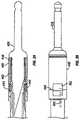
- the methodfurther may comprise providing an angling inserter tool.
- the angling inserter toolcomprises a handle portion, a base portion, and a tip assembly, the base portion being disposed between the handle portion and the tip assembly.
- the methodfurther may comprise distally advancing a central shaft of the tip assembly with rotation into an opening in the expandable vertebral implant to secure the angling inserter tool to the expandable vertebral implant.
- the methodfurther may comprise positioning the expandable vertebral implant in a patient's spine.
- the methodfurther may comprise distally advancing an internal shaft to cause the tip assembly to angulate with respect to a longitudinal axis of the angling inserter tool, wherein the internal shaft is coaxial with an outer cylinder of the base portion.
- the methodfurther may comprise rotating a primary drive shaft of the base portion to cause a gear member on the expandable vertebral implant to rotate thereby causing the expandable vertebral implant to expand, wherein the primary drive shaft is coaxial with the internal shaft.
- the methodfurther may comprise distally advancing an internal shaft, wherein advancing the shaft comprises rotating a knob on an outer cylinder to cause a drive shaft to distally advance.
- FIG. 1is a perspective view of an implant in accordance with an embodiment of the present invention
- FIG. 2is an exploded view of the implant of FIG. 1 ;
- FIG. 3is a cross-sectional view of the implant of FIG. 1 taken along line 3 - 3 of FIG. 1 ;
- FIG. 4is perspective view of an embodiment of an inner member of the implant of FIG. 1 ;
- FIG. 5is perspective view of an embodiment of an outer member of the implant of FIG. 1 ;
- FIG. 6is an elevated perspective view of one embodiment of a gear member of the implant of FIG. 1 ;
- FIG. 7is a bottom perspective view of the gear member of FIG. 6 ;
- FIG. 8is a perspective of one embodiment of a tool according to the present invention.
- FIG. 9is a cross-sectional view of the tool of FIG. 8 shown engaging an embodiment of an expandable implant according to the present invention.
- FIG. 10is a perspective view of another embodiment of an implant according to the present invention.
- FIG. 11is a perspective view of another embodiment of an endplate of an implant according to the present invention.
- FIG. 12is an exploded view of the endplate of FIG. 11 ;
- FIG. 13is a cross-sectional view of the endplate of FIG. 11 ;
- FIG. 14is a perspective view of an angling inserter tool of one embodiment of the present invention.
- FIG. 15is an exploded view of the angling inserter tool of FIG. 14 ;
- FIG. 16is a top view of the angling inserter tool of FIG. 14 ;
- FIG. 17is a cross-sectional view of the angling inserter tool of FIG. 14 ;
- FIG. 18is a cross-sectional view of one embodiment of a tip assembly of the angling inserter tool of FIG. 14 ;
- FIG. 19is an exploded view of the tip assembly of FIG. 18 ;
- FIG. 20is an elevated partial exploded view of the tip assembly of FIG. 18 ;
- FIG. 21is another partial exploded view of the tip assembly of FIG. 18 ;
- FIGS. 22 and 23are top views of one embodiment of the angling inserter tool of FIG. 14 showing angulation of the tip assembly;
- FIG. 24is a view of an expandable trial assembly of one embodiment of the present invention in a contracted position
- FIG. 25is a cross-sectional view of the expandable tip assembly of the expandable trial assembly of FIG. 24 in a contracted position
- FIG. 26is a view of the expandable trial assembly of FIG. 24 in an expanded position
- FIG. 27is a cross-sectional view of the expandable tip assembly of the expandable trial assembly of FIG. 24 in an expanded position
- FIG. 28is a cross-sectional view of one embodiment of the proximal end of the expandable trial assembly of FIG. 25 showing the scale portion;
- FIG. 29is a view of one embodiment of the proximal end of the trial assembly of FIG. 25 showing the scale portion.
- the implant 10preferably comprises an inner member 12 which may be telescopingly received within an outer member 14 .
- the implant 10further comprises a gear member 16 generally configured to effect translation of the inner member 12 with respect to the outer member 14 thereby allowing for expansion and contraction of the implant 10 .
- the inner member 12 , the outer member 14 , and the gear member 16are preferably centered along a longitudinal axis 18 and define a hollow interior portion which may be filled with bone material, bone growth factors, bone morphogenic proteins, or other materials for encouraging bone growth, blood vessel growth or growth of other tissue through the many apertures in the device.
- members 12 , 14 , and 16are made of a polyether ether ketone (PEEK) plastic material.
- PEEKpolyether ether ketone
- the members 12 , 14 , and 16may be made of a biologically inert metal alloys, such as titanium, or other suitable materials.
- the inner member 12has a generally cylindrical body 24 with a distal end 22 and a proximal end 36 .
- the body 24 of the inner member 12comprises an inner surface 28 and an outer surface 30 and generally defines a hollow interior portion 23 extending axially therethrough. At least part of the outer surface 30 preferably includes external threads 32 .
- Located proximate to the distal end 22 of the body 24are a plurality of tabs 38 which assist in connecting and positionally locating an endplate 20 .
- the body 24is configured and dimensioned to be cooperatively received within outer member 14 .
- the outer member 14has a generally cylindrical body 40 with a distal end 42 and a proximal end 44 .
- the body 40 of the outer member 14comprises an inner surface 46 and an outer surface 48 and generally defines a hollow interior portion 50 extending axially therethrough.
- the outer surface 48preferably has at least one slot 52 and an opening 54 configured and dimensioned to receive a portion of an implantation tool.
- the opening 54extends from the outer surface 48 to the hollow interior portion 50 and at least a portion of the opening 54 is threaded.
- the inner surface 46includes a channel 57 for receiving a locking member (discussed below).
- a lip 62is formed around the exterior of the distal end 42 of body 40 and is configured to cooperatively fit with a portion of the gear member 16 .
- a plurality of relief spaces or slots 63are radially spaced around lip 62 to facilitate a snapping engagement of the lip 62 with the gear member 16 .
- slots 63allow the lip 62 to deform slightly and contract in the radial direction to accommodate gear member 16 to snap on to lip 62 .
- the interior portion 50 of body 44is configured and dimensioned to cooperatively receive body 24 of inner member 12 within outer member 14 . In this regard, the dimensions of interior portion 50 of body 44 are greater than dimensions of body 24 of inner member 12 .
- the body 24 of the inner member 12includes a flattened portion 34 which extends at least in part from the distal end 22 to the proximal end 36 and includes a base member 37 having at least one lobe 39 located proximate to the distal end 36 of the body 24 .
- the body 40 of the outer member 14includes a flattened area 56 and at least one depression 58 on the inner surface 46 .
- the flattened area 56 of the outer member 14cooperatively aligns with the flattened portion 34 of the inner member 12 and the at least one depression 58 of outer member 14 receives the at least one lobe 39 of the inner member 12 .
- the flattened portion 34 and the flattened area 56 along with the lobes 39 and the depressions 58cooperate to allow the inner member 12 to linearly move with respect to the outer member 14 but prevent the inner member 12 from rotating with respect to the outer member 14 .
- the base member 37serves as a stop preventing the inner member 12 from rotating to a point of disengagement from outer member 14 .
- a gear member 16comprises a generally hollow body 64 extending from a distal end 66 to a proximal end 68 with a helical thread 70 along at least part of an inner wall 72 and an array of gear teeth 74 along a portion of the exterior wall 75 .
- the gear member 16is generally configured to rotatably connect to the distal end 42 of the outer member 14 and the internal helical thread 70 is configured to engage the external threads 32 of the inner member 12 to cause translation of the inner member 12 with respect to the outer member 14 .
- the gear member 16includes a cylindrical cutout feature 76 extending around the inner wall to cooperatively receive the lip 54 of the outer member 14 .
- the gear member 16may rotate freely with respect to the outer member 14 while being retained from longitudinal and lateral movement.
- the gear member 16also includes a series of cutouts 73 located proximate to the proximal end 68 for engaging a portion of a locking member.
- the gear teeth 74extend substantially from the proximal end 68 to the distal end 66 and extend around the entire periphery of at least a portion of the exterior wall 75 .
- the outer-most external diameter 78 of the gear member 16is sized to be the same as or slightly smaller than the smallest outer diameter of the endplates 20 , 62 and the outer member 14 . In this regard, when the implant 10 is viewed from the end in a plane perpendicular to the longitudinal axis 18 , the gear member 16 does not protrude radially outward from beyond the perimeter of the endplates 20 , 62 .
- the gear teeth 74extend a width 580 in a generally radial direction and generally extend radially outward to the outer diameter of the gear member 16 .
- the teeth 74may be designed to have a width 580 to accommodate the expected gear forces given the particular gear ratio, types of material used, and desired overall diameter of prosthetic device 10 .
- the larger the outer diameter to which the teeth 74 radially extendthe larger the teeth 74 may be designed while still maintaining the same gear ratio.
- the teeth 74when the teeth 74 are made larger, they generally have a better mechanical strength.
- the ability to design larger, wider, and stronger teeth 74is advantageous for embodiments where the implant 10 is made of PEEK, other plastic, or other non-metallic materials that may have less mechanical strength than, for instance, titanium.
- the outer-most diameter of the gear member 16may be as large as the outer diameter of the endplates 20 , 62 , and the teeth 74 extend radially to the outer-most diameter of the gear member 16 , a larger inner diameter of the gear member 16 may be manufactured without compromising mechanical gear strength. As a result, a larger overall inner diameter of the implant 10 may be accommodated which allows the packing of more bone material therein and facilitates bone fusion once the implant 10 is implanted.
- the teeth 74are exposed to the exterior of prosthetic device 10 . Because the teeth 74 are exposed around the periphery, little to no material is needed to cover up the exposed teeth, which generally makes the implant 10 lighter and easier to manufacture than prior art devices that require covering the gear teeth. In addition, the gear member 16 is more easily visible by a surgeon and more readily accessible by a rotation tool than devices that hide or cover gear teeth.
- the implant 10also includes a locking member 80 .
- the locking member 80may be provided to substantially restrict all relative movement between inner member 12 and outer member 14 , when, for example, the desired expansion of the prosthetic device 10 has been obtained.
- the locking member 80has a body portion 82 with a through-hole 84 .
- the body portion 82has at least one, but preferably two, outwardly extending, flexible arms 86 , 88 and at least one engagement member 90 .
- the locking member 80may include an alternate biasing member, such as a leaf spring.
- the locking member 80is configured and dimensioned to be received in the channel 57 of the outer member 14 in such a manner that the arms 86 , 88 rest against a shelf portion in the channel 57 and the through-hole 84 partially aligns with opening 54 .
- the engagement member 90preferably protrudes upwardly and is configured and dimensioned to engage the cutouts 73 of the gear member 16 to prevent the gear member 16 from rotating.
- endplates 20 , 62are shown wherein the endplate 20 connects to the inner member 12 and endplate 62 connects to the outer member 14 .
- endplate 20includes an extension portion 91 which is received in the interior portion 23 of inner member 12 , for example, in an interference or snap fit and includes a plurality of tabs 93 which interdigitate with tabs 38 to connect and position endplate 20 with respect to the inner member 12 .
- Endplate 62includes an extension portion 95 which engages the proximal end 44 of the outer member 14 , for example, in an interference or snap fit and includes a plurality of tabs 97 which interdigitate with tabs 60 to connect and position endplate 62 with respect to the outer member 14 .
- the endplates 20 , 62also preferably include hollow interior portions 99 , 101 which are in fluid communication with the hollow interior portions 23 , 50 of inner member 12 and outer member 14 , respectively.
- each endplate 20 , 62is generally annular in shape when viewed from the end or perpendicular to the longitudinal axis 18 . It is, however, contemplated that the endplates 20 , 62 can be other shapes including oblong, elliptical, kidney bean, polygonal, or geometric. Preferably, the endplates 20 , 62 are designed to resemble or mimic the footprint of the vertebral body to which the endplates will engage. In this regard, endplates 20 , 62 are configured to engage portions of the vertebrae in a predetermined orientation to maximize contact of the superior surface of the endplates 20 , 62 with bone.
- endplates 20 , 62can be varied to accommodate a patient's anatomy.
- the endplates 20 , 62have a wedge-shaped profile to accommodate the natural curvature of the spine.
- the natural curvature of the lumbar spineis referred to as lordosis.
- the angle formed by the wedgeshould be approximately between 3.5 degrees and 16 degrees so that the wedge shape is a lordotic shape which mimics the anatomy of the lumbar spine.
- the wedge shape profilemay result from a gradual increase in height from an anterior side to a posterior side to mimic the natural curvature, kyphosis, in other regions of the spine.
- the anglemay be between about ⁇ 4 degrees and ⁇ 16 degrees.
- the endplates 20 , 40include a plurality of mounting holes 92 spaced around the perimeter of each endplate 20 , 40 for receiving insertable bone engaging members 94 .
- bone engaging members 94comprise conical spikes 96 each having a cylindrical base portion 98 configured to fit within holes 92 , for instance, by press-fit or by threaded engagement.
- differently shaped bone engaging members 100may be used, or in other embodiments no bone engaging members may be used.
- endplates 20 , 62have chamfered edges 100 around the perimeter to facilitate insertion and/or accommodate the shape of the vertebral bodies which they engage.
- the superior or bone engaging surfaces 102 , 104 of endplates 20 , 62may also include numerous types of texturing to provide better initial stability and/or grasping contact between the end plate and the respective vertebrae.
- the texturingis a plurality of teeth 106 .
- the endplates 20 , 62may also include radio-opaque material, such as tantalum markers 108 , which aid in providing location markers in radiographic images.
- the length, diameter, and shape of prosthetic device 10may vary to accommodate different applications, different procedures, implantation into different regions of the spine, or size of vertebral body or bodies being replaced or repaired.
- implant 10may be expandable to a longer distance to replace multiple vertebral bodies.
- endplates 20 , 62can be sized and shaped as well as positioned to accommodate different procedures and approached to the spine.
- endplates 20 , 62may be made smaller for smaller statured patients or for smaller regions of the cervical spine.
- the implant 10may be expanded by a tool 110 that includes a gear member 112 at its distal end 114 .
- the tool 110extends along a tool axis 514 and in operation the tool 110 is configured to engage the implant 10 such that the tool axis 514 is generally perpendicular to the longitudinal axis 18 .
- the gear member 112is configured to engage teeth 74 of the gear member 16 such that when the gear member 112 is rotated about the axis of the tool 110 , the gear member 16 of the implant 10 is rotated about the longitudinal axis 18 and the inner member 12 translates along the longitudinal axis 18 to either expand or contract the implant 10 .
- the tool 110may include a central shaft 116 having a threaded distal tip portion 118 that extends distally beyond gear member 112 to facilitate location and mounting of tool 110 with the implant 10 .
- the threaded distal tip portion 118preferably includes a generally conical end portion and may be configured to extend radially through the opening 54 and threadably engage opening 54 in the outer member 14 .
- prosthetic device 10at least one, but preferably a plurality of mounting features or slots 52 are provided along the outer surface 48 of outer member 14 .
- the tool 110includes at least one, but preferably two, articulating arms 120 , 122 that engage slots 52 for better engagement of the tool 110 with the implant 10 during insertion of the implant 10 .
- the tool 110may include arms 120 , 122 that do not articulate.
- the tool 110initially engages the slots 52 of the implant 10 via the arms 120 , 122 and gear member 112 engages gear member 16 via their respective interdigitating teeth.
- a control member on the proximal end of the tool 110(not shown) is manipulated to advance the central shaft 116 toward opening 54 .
- the threaded tip portion 118enters into opening 54 engaging the threads in opening 54 as well as engaging the through-hole 84 of locking member 80 .
- the central shaft 116is not movable with respect to the tool 110 . In that embodiment, the entire tool 110 is moved so that the central shaft can enter and engage the opening 54 and the through-hole 84 .
- the though-hole 84is offset from opening 54 , thus, when threaded tip 118 engages and advances into the opening 54 and the through-hole 84 , the locking member 80 is pulled downwardly, riding along the conical edge of the tip 118 until the through-hole 84 is aligned with the opening 54 . As the locking member 80 is pulled downwardly, the arms 82 , 84 are flexed and the engagement member 90 disengages from the cutout 73 of the gear member 16 allowing the gear member 16 to rotate freely. The gear member 112 of tool 110 is then rotated via opening 114 which, in turn, rotates gear member 16 .
- the rotation of gear member 16results in the movement of inner member 12 causing the implant 10 to either expand or contract, depending on the direction the gear member 16 is rotated.
- the tool member 110is disengaged from implant 10 .
- the locking member 80returns to the back to its initial position because of the arms 82 , 84 returning back to their unflexed, at-rest state.
- the initial position of locking member 80prevents the gear member 16 from turning because of the engagement of engagement member 90 with the cutouts 73 . In that regard, implant 10 is locked from movement when the locking member 80 is in its initial position.
- the benefit provided by the present locking mechanismis that it allows for a positive lock that engages and disengages automatically with the engagement and disengagement of the tool 110 with the implant 10 , which minimizes the steps the surgeon must perform during the procedure.
- the endplates 202 and outer member 204each include at least one screw hole 206 , 208 , but, preferably, each include two screw holes.
- the screw holes 206 , 208are configured and dimensioned to receive screws 210 , 212 .
- the screw holes 206 , 208are angled such that when the screws 210 , 212 are seated in the screw holes 206 , 208 , the screws 210 , 212 will extend outwardly from the superior surface 214 of endplate 202 and inferior surface 216 of outer member 204 .
- Endplate 202 and outer member 204also preferably include a locking element 218 , 220 which, in a first position, allow the screws 210 , 212 to back out from the seated position and, in a second position, block the screws 210 , 212 from backing out of the seated position.
- the screws 210 , 212can be installed through the screw holes 206 , 208 in such a manner as to purchase into the adjacent vertebral bodies.
- the locking elements 218 , 220can be actuated to block the screws 210 , 212 from backing out of their installed position.
- the inclusion of screws 210 , 212 in the endplate 202 and the outer member 204provides for additional fixation of the implant 200 in the intervertebral space.
- endplate 250is similar to endplate 20 but includes the additional functionality of being poly-axially rotatable with respect to an implant.
- endplate 250includes a generally arcuate extension portion 252 which is received in an interior portion 253 of a receiving member 254 in such a manner as to allow the endplate 250 to move poly-axially with respect to the receiving member 254 .
- the receiving member 254is received in an interior portion 255 of a locking ring 256 .
- the receiving member 254preferably includes a neck portion 258 as well as a plurality of tabs 260 .
- the neck portion 258is configured and dimensioned to be received within a hollow interior of an inner member, for example, in an interference or snap fit, and the plurality of tabs 260 interdigitate with tabs to connect and position the receiving member 254 with respect to an inner member.
- the receiving member 254further includes a plurality of fingers 262 configured to cooperatively receive the extension portion 252 of endplate 250 .
- a plurality of relief spaces or slots 264are radially spaced between fingers 262 to allow fingers 262 to bend or flex radially.
- the locking ring 256has a generally annular, c-shape and includes an exterior wall 266 , an interior wall 268 , and ends 277 , 279 .
- the interior wall 268preferably defines and interior portion 255 .
- the interior wall 268includes a plurality of channel 270 which are spaced radially along the locking ring 256 .
- the channels 270allow the locking ring 256 to bend or flex radially.
- the ends 277 , 279each include openings 280 , 282 which may be partially threaded.
- a locking element 284is configured and dimensioned to be threadingly received in the openings 280 , 282 . It also contemplated that that locking element 284 can engage the ends 277 , 279 by other non-threaded means, such as a sliding fit.
- the endplate 250includes a plurality of mounting holes 286 spaced around the perimeter of the endplate 250 for receiving insertable bone engaging members.
- bone engaging memberscomprise conical spikes each having a cylindrical base portion configured to fit within holes 286 , for instance, by press-fit or by threaded engagement.
- differently shaped bone engaging membersmay be used, or in other embodiments no bone engaging members may be used.
- endplate 250has chamfered edges 288 around the perimeter to facilitate insertion and/or accommodate the shape of the vertebral bodies which they engage.
- the superior or bone engaging surfaces 290 of endplate 250may also include numerous types of texturing to provide better initial stability and/or grasping contact between the end plate and the respective vertebrae.
- the texturingis a plurality of teeth 292 .
- the endplate 250may also include radio-opaque material, such as tantalum markers 294 , which aid in providing location markers in radiographic images.
- the endplate 250can move in poly-axial fashion with respect to the implant to accommodate the anatomy of the adjacent vertebral body as well as accommodate the natural curvature of the spine, such as kyphosis and lordosis. More specifically, the arcuate extension portion 252 is free to move in the interior portion 253 of the receiving portion 254 .
- the fingers 262are generally compliant and can flex to accommodate the movement of the arcuate extension portion 252 .
- an angling inserter tool 300is shown that may be used to expand the implant 10 in accordance with embodiments of the present invention.
- the tool 300is configured to hold the implant 10 .
- the angling inserter tool 300may comprise a handle portion 302 , a cylindrical base portion 304 , and a tip assembly 306 .
- the cylindrical base portion 304is disposed between the handle portion 302 and the tip assembly 306 .
- the angling inserter tool 300has a longitudinal or tool axis 308 that passes through the tool 300 from proximal end 310 to distal end 312 .
- the tip assembly 306can be angled relative to the tool axis 308 , for example, allowing the implant to be placed around or behind certain anatomical structures.
- the tool 300includes a primary gear mechanism (e.g., gears 356 , 412 , 414 , 416 , 410 ), for example, configured to drive gear member 16 on the implant 10 it holds, and the tool 300 also includes a second gear mechanism (e.g., distal gear 368 , central gear 402 , proximal gear portion 398 ), for example, configured to attached or release the implant 10 from the tool 300 .
- a primary gear mechanisme.g., gears 356 , 412 , 414 , 416 , 410
- a second gear mechanisme.g., distal gear 368 , central gear 402 , proximal gear portion 398
- the cylindrical base portion 304includes an outer cylinder 314 .
- the outer cylinder 314preferably includes arms 316 that extend distally from the outer cylinder 314 , as best seen in FIGS. 18 and 19 .
- One of the arms 316may include a bent portion 317 at least a portion of which extends radially outward from the outer cylinder 314 .
- Each of the armsmay include an opening 318 .
- the openings 318 in each of the arms 316may be axially aligned and configured to receive a pin 376 , as best seen in FIGS. 18 and 19 .
- the pin 376may rotatably secure the tip assembly 306 to the cylindrical base portion 304 allowing the tip assembly 306 to angulate with respect to the tool axis 308 .
- the cylindrical base portion 304also includes an internal shaft 320 .
- the internal shaft 320may be coaxial with the outer cylinder 314 wherein the internal shaft 320 is received within the outer cylinder 314 .
- the internal shaft 320is a generally cylindrical body.
- the internal shaft 320can translate longitudinally with respect to the outer cylinder 314 .
- the internal shaft 320has an angulated distal end 322 , which may be offset from tool axis 308 . As best seen in FIG. 19 , the angulated distal end 322 may include tabs 324 which may each include an opening 326 .
- the openings 326 in each of the tabs 324may be axially aligned and configured to receive a pin 328 as shown on FIG. 19 .
- the pin 328may secure the internal shaft 320 to a linking arm 330 coupling the tip assembly 306 to the internal shaft 320 .
- embodiments of the cylindrical base portion 304also include a knob 332 generally configured to effect translation of the internal shaft 320 with respect to the outer cylinder 314 .
- the knob 332is disposed on the outer cylinder 314 .
- At least a part of the knob 332may include internal threads 334 , as best seen in FIG. 15 .
- the internal threads 334engage one or more blocks 336 , as best seen in FIGS. 15 and 17 .
- the blocks 336are received in one or more openings 338 in the internal shaft 320 and extend through one or more windows 340 in the outer cylinder 314 to engage the internal threads 334 of the knob 332 .
- the windows 340 in the outer cylinder 314may be longer than the blocks 336 , allowing the blocks 336 to move longitudinally in the windows 340 .
- rotation of the knob 332 on the outer cylinder 314should cause the blocks 336 to move thereby causing the internal shaft 320 to translate within the outer cylinder 314 .
- the internal shaft 320may extend through the outer cylinder 314 or retract into the outer cylinder 314 , depending for example on the direction of the rotation of the knob 332 . Because the linking arm 330 couples the internal shaft 320 to the tip assembly 306 , translation of the internal shaft 320 should move the tip assembly 306 causing rotation of the tip assembly about the pin 376 , as best seen in FIGS. 22 and 23 .
- translation of the internal shaft 320should move the tip assembly 306 causing rotation of the tip assembly 306 about the pin 376 .
- advancement of the internal shaft 320 through the outer cylinder 314should effect rotation of the tip assembly 306 about the pin 376 in a first direction (as best seen in FIG. 22 ), while retraction of the internal shaft into the outer cylinder 314 should effect rotation of the tip assembly 306 about the pin 376 in an opposite direction (as best seen in FIG. 23 ).
- Rotation of the tip assembly 306may be monitored using viewing window 342 and visual indicators 344 . As illustrated by FIGS.
- visual indicators 344may be disposed on the internal shaft 320 .
- the visual indicators 344may be markings, such as numbers, etchings, lines, combinations thereof, or the like, that provide a visual indication of the degree of rotation.
- the visual indicators 344 on the internal shaft 320may generally aligned with a viewing window 342 in the outer cylinder 314 .
- the visual indicators 344should allow accurate measurement of the angulation of the tip assembly 306 even when the tip assembly 306 itself may be obscured from viewing.
- ring 346may secure the knob 332 on the outer cylinder 314 in accordance with embodiments of the present invention. As illustrated, the ring 346 may be disposed on the outer cylinder 314 proximally to the knob 332 . A set screw 348 disposed through opening 350 in the ring 346 may engage opening 352 in the outer cylinder 314 to secure the ring 346 on the outer cylinder 314 .
- embodiments of the cylindrical base portion 304also include a primary drive shaft 354 .
- the primary drive shaft 354may be coaxial with the internal shaft 320 wherein the primary drive shaft 354 is receiving within the internal shaft 320 .
- the primary drive shaft 354may be a generally cylindrical body.
- the primary drive shaft 354includes a distal gear 356 , which may be a bevel gear, for example.
- the distal gear 356is configured to fixedly engage distal end 358 of the primary drive shaft 354 , as best seen in FIG. 19 .
- the primary drive shaft 354may be configured to rotate with respect to the internal shaft 320 .
- a driving instrument(not shown) may be used to rotate the primary drive shaft 354 .
- the driving instrumentmay engage the primary drive shaft 354 at proximal end 310 through opening 560 of handle portion 302 , as best seen in FIG. 15 .
- the distal gear 356may be configured to engage one or more corresponding gears (e.g., gears 412 , 414 , 416 ) in the tip assembly 306 to cause rotation of implant engagement gear 410 (see, e.g., FIGS. 18 and 19 ).
- the cylindrical base portion 304also includes a secondary drive shaft 366 .
- the secondary drive shaft 366may be coaxial with the primary drive shaft 354 wherein the secondary drive shaft 366 is received the primary drive shaft 354 .
- the secondary drive shaft 366includes a gear 368 at distal end 312 , which may be a bevel gear, for example.
- the secondary drive shaft 366may be configured to rotate with respect to the outer shaft 314 .
- a driving instrument(not shown) may be used to rotate the secondary drive shaft 366 . The driving instrument may engage the secondary drive shaft 366 at the proximal end 310 through the opening 560 in the handle portion, as best seen in FIG. 15 .
- the gear 368may be configured to engage one or more corresponding gears (e.g., gear 402 , gear portion 398 ) in the tip assembly 306 to cause extension of central shaft 392 (see, e.g., FIGS. 18 and 19 ).
- gearse.g., gear 402 , gear portion 398
- the handle portion 302includes a cylindrical portion 362 and a handle 364 .
- the handle 364may preferably extend downward from the cylindrical portion 362 .
- Opening 560may be disposed in the handle portion 302 at the proximal end 310 so that the secondary drive shaft 366 and the primary drive shaft 354 can be accessed.
- At least a portion of the cylindrical base portion 304may be disposed in the cylindrical portion 362 .
- a locking member 365may engage the outer cylinder 314 of the cylindrical base portion 304 to secure the cylindrical base portion 304 to the handle portion 302 .
- the locking member 365may extend through an opening in the cylindrical portion 362 .
- the tip assembly 306includes an upper plate 372 and a base portion 374 .
- the upper plate 372 and the base portion 374may be secured to one another by one or more pins 388 .
- two pins 388are used to secure the upper plate 372 and the base portion 374 .
- the pins 388may be configured to be received in openings 386 in the upper plate 372 and openings 390 in the base portion 374 .
- the tip assembly 306may be rotatably secured to the cylindrical base portion 304 with the pin 376 .
- the pin 376is received in an opening 378 in upper tab 380 of the upper plate 372 and in lower tab 384 of opening 382 of the base portion 374 .
- a bushing 385may be disposed about at least a portion of the pin 376 .
- the pin 376has a pin axis 377 (as shown on FIG. 18 ) about which the tip assembly 306 may rotate.
- the upper plate 372may further include an outer tab 506 having a corresponding opening 408 .
- the outer tab 506may be offset from the tool axis 308 and configured to receive the pin 404 .
- the pin 404may secure the tip assembly 306 to the linking arm 330 coupling the tip assembly 306 to the internal shaft 320 . Accordingly, advancement or retraction of the internal shaft 320 should cause rotation of the tip assembly 306 about the pin axis 377 .
- the tip assembly 306preferably further includes a central shaft 392 disposed in through-bore 394 (as best seen on FIG. 19 ) in the base portion 374 .
- the central shaft 392preferably may include a threaded distal tip portion 396 that extends distally beyond the implant engagement gear 410 to facilitate location and mounting of the angling inserter tool 300 with the implant 10 (see, e.g., FIG. 2 ) in accordance with embodiments of the present invention.
- the central shaft 392may also include a proximal gear portion 398 that engages corresponding gears to facilitate extension of the central shaft 392 through the through-bore 394 .
- a proximal gear portion 398that engages corresponding gears to facilitate extension of the central shaft 392 through the through-bore 394 .
- the proximal gear portion 398may engage a secondary central gear 402 , which may be a bevel gear.
- the secondary central gear 402may be disposed about the pin 376 and rotate about the pin axis 377 .
- the secondary central gear 402may engage gear 368 on the secondary drive shaft 366 of the cylindrical base portion 304 . Accordingly, rotation of the secondary drive shaft 366 about the tool axis 308 should cause rotation of the secondary central gear 402 about the pin axis 377 which should in turn drive the proximal gear portion 398 causing rotation of the central shaft 392 and movement of the central shaft through the through-bore 394 .
- the central shaft 392should extend through the base portion 374 or retract into the base portion 374 , depending for example on the direction of rotation of the secondary drive shaft 366 .
- the tip assembly 306preferably further includes an implant engagement gear 410 .
- the implant engagement gear 410is configured to engage teeth 74 of the gear member 16 of the implant 10 (see, e.g., FIG. 2 ) such that when the implant engagement gear 410 is rotated, the gear member 16 of the implant 10 is rotated about the longitudinal axis 18 and the inner member 12 translates along the longitudinal axis to either expand or contract the implant 10 .
- a series of gearse.g., gears 412 , 414 , and 416 ) transfer rotation of the primary drive shaft 354 to the implant engagement gear 410 .
- rotation of implant engagement gear 410causes rotation of distal gear 356 .
- the distal gear 356may engage a first primary central gear 412 disposed on the pin 376 such that rotation of the distal gear 356 causes rotation of the first primary central gear 412 about the pin axis 377 .
- the first primary central gear 412may be a bevel gear, for example.
- the distal gear 356 and the first primary central gear 412may have rotational axes that are perpendicular, for example, the tool axis 308 and the pin axis 377 .
- a second primary central gear 414may be fixedly engaged to the first primary central gear 412 such that rotation of the central gear 412 causes rotation of the second primary central gear 414 .
- the second primary central gear 414may engage secondary transfer gear 416 such that rotation of the second primary central gear 414 causes rotation of the primary transfer gear 416 .
- the gears 414 , 416may each be spur gears, for example.
- Pin 418may secure primary transfer gear 416 to upper plate 372 .
- the primary transfer gear 416may rotate about the pin 418 .
- the primary transfer gear 416may engage the implant engagement gear 410 such that rotation of the primary transfer gear 416 causes rotation of the implant engagement gear 410 . Accordingly, when the primary drive shaft 354 is rotated, the implant engagement gear 410 rotates causing the implant 10 to either expand or contract.
- the angling inserter tool 300initially engages the slots 52 of the implant 10 via the arms 400 and implant engagement gear 410 engages gear member 16 via their respective teeth.
- the secondary drive shaft 366may then be driven (e.g., rotated) causing the second gear mechanism (e.g., distal gear 368 , central gear 402 , proximal gear portion 398 ) to enable actuation.
- the second gear mechanisme.g., distal gear 368 , central gear 402 , proximal gear portion 398
- rotation of the secondary drive shaft 366rotates the distal gear 368 about the tool axis 308 which rotates the secondary central gear 402 about the pin axis 376 which rotates the proximal gear portion 398 about the tool axis 308 to cause actuation.
- the threaded tip portion 396enters into the opening 54 engaging the threads in opening 54 as well as engaging the through-hole 84 of locking member 80 .
- the locking member 80should be engaged such that the gear member 16 may rotate freely.
- the implant 10may then be placed in a desired location, for example, in the vertebral space.
- the tip assembly 306can be angled relative to the tool axis 308 , allowing the implant to be placed around or behind certain anatomical structures.
- the knob 332 on the tool 300may be rotated to cause the tip assembly 306 to angulate.
- rotation of the knob 332may cause longitudinal movement of the blocks 336 to cause translation of the internal shaft 320 , thus moving the tip assembly 306 and causing rotation of the tip assembly 306 about the pin 376 .
- the primary drive shaft 354may then be driven (e.g., rotated) causing the primary gear mechanism (e.g., gears 356 , 412 , 414 , 416 ), for example, to rotate the gear member 16 on the implant 10 .
- the primary gear mechanisme.g., gears 356 , 412 , 414 , 416
- rotation of the primary drive shaft 354rotates the distal gear 356 about the tool axis 308 which rotates the first primary central gear 412 about the pin axis 377 which rotates the second primary central gear 414 about the pin axis 377 .
- Rotation of the second primary central gear 414rotates the primary transfer gear 416 about an axis generally parallel to the pin axis 377 which rotates the implant engagement gear 410 about an axis generally parallel to pin axis 377 .
- the implant engagement gear 410engages the gear member 16 on the implant causing the gear member 16 to rotate about longitudinal axis 18 .
- the rotation of the gear member 16results in the movement of the inner member 12 causing the implant 10 to either expand or contract, depending on the direction the gear member 16 is rotated.
- the angling inserter tool 300may be disengaged from the implant 10 .
- the angling inserter tool 300can be disengaged from the implant 10 even with the tip assembly 306 at any angle with respect to the tool axis 308 .
- the locking member 80returns back to its initial state, thus preventing the gear member 16 from rotating as previously described.
- angling inserter tool 300may be used for insertion and expansion of any of a variety of expandable implants for implantation into the spine, including vertebral body spacers for vertebral body replacement and expandable cages for insertion into the disc space.
- an expandable trial assembly 420is shown that may be used in the implanting of an expandable implant, such as implant 10 ( FIG. 2 ), in accordance with embodiments of the present invention.
- the trial assembly 420may be used to distract adjacent vertebral bodies and to give a measurement of the distraction. In this manner, the trial assembly 420 may give a measurement of the desired height for the subsequent expansion of the implant 10 , for example.
- the expandable trial assembly 420may comprise a handle portion 422 , a cylindrical base portion 424 , and an expandable tip assembly 426 .
- the handle portion 422extends downward from the cylindrical base portion 424 .
- the expandable tip assembly 426may be disposed at the distal end 432 of the cylindrical base portion 424 .
- the expandable trial assembly 420has a tool axis that extends through the trial assembly 420 from the proximal end 430 to the distal end 432 of the cylindrical base portion 424 .
- the cylindrical base portion 424may include an outer cylinder 434 and a drive shaft 436 .
- the drive shaft 436may be coaxial with the outer cylinder 434 wherein the drive shaft 435 is inside the outer cylinder 434 .
- the drive shaft 436is a generally cylindrical body.
- the drive shaft 436can rotate about the tool axis 428 .
- a distal gear 438is located on the drive shaft 436 at the distal end 432 , as best seen in FIGS. 25 and 27 . Rotation of the drive shaft 436 rotates the distal gear 438 .
- the teeth of the distal gear 438are not illustrated for simplicity.
- the cylindrical base portion 424further includes scale 440 at proximal end 430 .
- the scale 440may be in the general form of a cylindrical section. As best seen in FIGS. 28 and 29 , at least a portion of the scale 440 may be internally threaded with threads 442 .
- the scale 440may be keyed to the outer cylinder 434 .
- locking mechanism 444may secure the scale 440 to the outer cylinder 434 , as best seen in FIG. 28 .
- at least a portion of the drive shaft 436may be threaded, for example, in the general region of the scale 440 .
- the threaded portion 446 of the drive shaft 436may engage the threads 442 of the scale 440 . Accordingly, rotation of the drive shaft 426 should cause the scale 440 to move longitudinally.
- Visual indicators 448 , 450may be placed on the scale and/or the outer cylinder 434 to show, for example, the amount of expansion of the expandable tip assembly 426 .
- the visual indicators 448 , 450may be in the form of numbers, lines, combinations thereof or the like etched or otherwise formed on the scale 440 and/or the outer cylinder 434 .
- the scale 440also includes a viewing window 452 .
- the expandable tip assembly 426may include a housing 454 which may be in the form of a rounded end.
- the expandable tip assembly 426further may include an outer member 456 and an inner member 458 which may be telescopingly received within the outer member 456 .
- the outer member 456may generally comprise a generally cylindrical body 460 having external threads 462 on at least a portion thereof.
- An endplate 464may be coupled to the outer member 456 .
- the inner member 458may comprise a generally cylindrical body 466 having external threads 468 on at least a portion thereof.
- An endplate 470may be coupled to the inner member 458 .
- trial endplates 464 , 470are shown on the tip assembly 426 , it should be appreciated that endplates having a different footprint may be used in accordance with embodiments of the present invention.
- the endplates 464 , 470may be articulating (e.g., ball and socket type joint) to allow for measurement of sagittal alignment/angulation in addition to height.
- One or more pins 472may be used to secure the inner and outer members 456 , 458 from rotational movement.
- the pins 472may be disposed in corresponding slots 474 (best seen in FIG. 26 ) of the inner and outer members 456 , 458 .
- the expandable tip assembly 426may further include upper gear member 476 and lower gear member 478 .
- the upper and lower gear members 476 , 478may each include outer gear teeth on at least a portion of their exterior surfaces that engage the distal gear 438 of the cylindrical base portion 424 . Accordingly, rotation of the distal gear 438 about the tool axis 430 should cause the upper and lower gear members 476 , 478 to each rotate about the tip axis 480 , as best seen in FIGS. 25 and 27 .
- the upper gear member 476is engaged with the external threads 462 of the outer gear member 458 and the lower gear member 478 is engaged with the external threads 468 of the inner member 458 .
- rotation of the upper and lower gear members 476 , 478should cause the tip assembly 426 to either expand or contract.
- rotation in one directionshould cause the endplates 464 , 470 to expand (or translate vertically outward) while rotation in the opposite direction should cause the endplates 464 , 470 to contract (or translate vertically inward).
- the trial assembly 420may be inserted into a desired position in a patient's spine, for example, in a vertebral space, in a contracted position, as shown in FIGS. 24 and 25 .
- the drive shaft 436may then be rotated which causes expansion of the expandable tip assembly 426 .
- FIGS. 26 and 27illustrate the tip assembly 426 in an expanded position.
- rotation of the drive shaft 436rotates the distal gear 438 about the tool axis 428 which in turn rotes upper gear member 476 and lower gear member 478 about the tip axis 480 .
- Rotation of the upper gear member 476 and the lower gear member 478results in movement of the outer member 456 and the inner member 458 causing the expandable tip assembly 426 to either expand or contract, depending on the direction the drive shaft 436 is rotated.
- the heightcan be measured using the scale 440 at proximal end 430 .
- the tip assembly 426can then be contracted by rotation of the drive shaft 436 and then removed from the patient's body.
- An expandable implantsuch as implant 10 , can then be positioned in the patient's body in a manner that will be evident to one of ordinary skill in the art with the benefit of this disclosure. Once positioned in the body, the expandable implant can then be expanded to a desired height based on the measured height of the expandable trial assembly 420 .
Landscapes
- Health & Medical Sciences (AREA)
- Engineering & Computer Science (AREA)
- Biomedical Technology (AREA)
- Orthopedic Medicine & Surgery (AREA)
- Neurology (AREA)
- Transplantation (AREA)
- Heart & Thoracic Surgery (AREA)
- Oral & Maxillofacial Surgery (AREA)
- Cardiology (AREA)
- Vascular Medicine (AREA)
- Life Sciences & Earth Sciences (AREA)
- Animal Behavior & Ethology (AREA)
- General Health & Medical Sciences (AREA)
- Public Health (AREA)
- Veterinary Medicine (AREA)
- Physical Education & Sports Medicine (AREA)
- Prostheses (AREA)
Abstract
Description
Claims (16)
Priority Applications (2)
| Application Number | Priority Date | Filing Date | Title |
|---|---|---|---|
| US16/664,980US11298243B2 (en) | 2010-04-12 | 2019-10-28 | Angling inserter tool for expandable vertebral implant |
| US17/656,659US12279971B2 (en) | 2010-04-12 | 2022-03-28 | Angling inserter tool for expandable vertebral implant |
Applications Claiming Priority (7)
| Application Number | Priority Date | Filing Date | Title |
|---|---|---|---|
| US12/758,529US8282683B2 (en) | 2010-04-12 | 2010-04-12 | Expandable vertebral implant |
| US13/333,227US8591585B2 (en) | 2010-04-12 | 2011-12-21 | Expandable vertebral implant |
| US13/421,411US8870880B2 (en) | 2010-04-12 | 2012-03-15 | Angling inserter tool for expandable vertebral implant |
| US14/281,458US9345588B2 (en) | 2010-04-12 | 2014-05-19 | Angling inserter tool for expandable vertebral implant |
| US15/139,684US9913735B2 (en) | 2010-04-12 | 2016-04-27 | Angling inserter tool for expandable vertebral implant |
| US15/878,601US10492928B2 (en) | 2010-04-12 | 2018-01-24 | Angling inserter tool for expandable vertebral implant |
| US16/664,980US11298243B2 (en) | 2010-04-12 | 2019-10-28 | Angling inserter tool for expandable vertebral implant |
Related Parent Applications (1)
| Application Number | Title | Priority Date | Filing Date |
|---|---|---|---|
| US15/878,601ContinuationUS10492928B2 (en) | 2010-04-12 | 2018-01-24 | Angling inserter tool for expandable vertebral implant |
Related Child Applications (1)
| Application Number | Title | Priority Date | Filing Date |
|---|---|---|---|
| US17/656,659ContinuationUS12279971B2 (en) | 2010-04-12 | 2022-03-28 | Angling inserter tool for expandable vertebral implant |
Publications (2)
| Publication Number | Publication Date |
|---|---|
| US20200054463A1 US20200054463A1 (en) | 2020-02-20 |
| US11298243B2true US11298243B2 (en) | 2022-04-12 |
Family
ID=46796707
Family Applications (6)
| Application Number | Title | Priority Date | Filing Date |
|---|---|---|---|
| US13/421,411ActiveUS8870880B2 (en) | 2010-04-12 | 2012-03-15 | Angling inserter tool for expandable vertebral implant |
| US14/281,458Active2030-06-10US9345588B2 (en) | 2010-04-12 | 2014-05-19 | Angling inserter tool for expandable vertebral implant |
| US15/139,684Active2030-04-21US9913735B2 (en) | 2010-04-12 | 2016-04-27 | Angling inserter tool for expandable vertebral implant |
| US15/878,601ActiveUS10492928B2 (en) | 2010-04-12 | 2018-01-24 | Angling inserter tool for expandable vertebral implant |
| US16/664,980Active2030-12-06US11298243B2 (en) | 2010-04-12 | 2019-10-28 | Angling inserter tool for expandable vertebral implant |
| US17/656,659Active2031-08-10US12279971B2 (en) | 2010-04-12 | 2022-03-28 | Angling inserter tool for expandable vertebral implant |
Family Applications Before (4)
| Application Number | Title | Priority Date | Filing Date |
|---|---|---|---|
| US13/421,411ActiveUS8870880B2 (en) | 2010-04-12 | 2012-03-15 | Angling inserter tool for expandable vertebral implant |
| US14/281,458Active2030-06-10US9345588B2 (en) | 2010-04-12 | 2014-05-19 | Angling inserter tool for expandable vertebral implant |
| US15/139,684Active2030-04-21US9913735B2 (en) | 2010-04-12 | 2016-04-27 | Angling inserter tool for expandable vertebral implant |
| US15/878,601ActiveUS10492928B2 (en) | 2010-04-12 | 2018-01-24 | Angling inserter tool for expandable vertebral implant |
Family Applications After (1)
| Application Number | Title | Priority Date | Filing Date |
|---|---|---|---|
| US17/656,659Active2031-08-10US12279971B2 (en) | 2010-04-12 | 2022-03-28 | Angling inserter tool for expandable vertebral implant |
Country Status (1)
| Country | Link |
|---|---|
| US (6) | US8870880B2 (en) |
Cited By (2)
| Publication number | Priority date | Publication date | Assignee | Title |
|---|---|---|---|---|
| US11554025B1 (en)* | 2019-08-19 | 2023-01-17 | Nuvasive, Inc. | Expandable implant expansion driver |
| US20240009000A1 (en)* | 2021-04-02 | 2024-01-11 | Nuvasive, Inc. | Expansion driver |
Families Citing this family (174)
| Publication number | Priority date | Publication date | Assignee | Title |
|---|---|---|---|---|
| RU2184341C1 (en)* | 2001-03-07 | 2002-06-27 | Государственное унитарное предприятие "Конструкторское бюро приборостроения" | Guided missile |
| US8597360B2 (en) | 2004-11-03 | 2013-12-03 | Neuropro Technologies, Inc. | Bone fusion device |
| US8219178B2 (en) | 2007-02-16 | 2012-07-10 | Catholic Healthcare West | Method and system for performing invasive medical procedures using a surgical robot |
| US10893912B2 (en) | 2006-02-16 | 2021-01-19 | Globus Medical Inc. | Surgical tool systems and methods |
| US10653497B2 (en) | 2006-02-16 | 2020-05-19 | Globus Medical, Inc. | Surgical tool systems and methods |
| US10357184B2 (en) | 2012-06-21 | 2019-07-23 | Globus Medical, Inc. | Surgical tool systems and method |
| US8088163B1 (en) | 2008-02-06 | 2012-01-03 | Kleiner Jeffrey B | Tools and methods for spinal fusion |
| US20210378834A1 (en) | 2008-05-22 | 2021-12-09 | Spinal Surgical Strategies, Inc., A Nevada Corporation D/B/A Kleiner Device Labs | Spinal fusion cage system with inserter |
| US8545566B2 (en)* | 2008-10-13 | 2013-10-01 | Globus Medical, Inc. | Articulating spacer |
| US8366748B2 (en) | 2008-12-05 | 2013-02-05 | Kleiner Jeffrey | Apparatus and method of spinal implant and fusion |
| US9247943B1 (en) | 2009-02-06 | 2016-02-02 | Kleiner Intellectual Property, Llc | Devices and methods for preparing an intervertebral workspace |
| CN101627931B (en)* | 2009-08-06 | 2010-12-01 | 雷伟 | A kind of artificial cervical compound joint |
| US10973656B2 (en) | 2009-09-18 | 2021-04-13 | Spinal Surgical Strategies, Inc. | Bone graft delivery system and method for using same |
| US20170238984A1 (en) | 2009-09-18 | 2017-08-24 | Spinal Surgical Strategies, Llc | Bone graft delivery device with positioning handle |
| US8906028B2 (en) | 2009-09-18 | 2014-12-09 | Spinal Surgical Strategies, Llc | Bone graft delivery device and method of using the same |
| US9629729B2 (en) | 2009-09-18 | 2017-04-25 | Spinal Surgical Strategies, Llc | Biological delivery system with adaptable fusion cage interface |
| US10245159B1 (en) | 2009-09-18 | 2019-04-02 | Spinal Surgical Strategies, Llc | Bone graft delivery system and method for using same |
| US8870880B2 (en)* | 2010-04-12 | 2014-10-28 | Globus Medical, Inc. | Angling inserter tool for expandable vertebral implant |
| US8518087B2 (en) | 2011-03-10 | 2013-08-27 | Interventional Spine, Inc. | Method and apparatus for minimally invasive insertion of intervertebral implants |
| US8394129B2 (en) | 2011-03-10 | 2013-03-12 | Interventional Spine, Inc. | Method and apparatus for minimally invasive insertion of intervertebral implants |
| US9308050B2 (en) | 2011-04-01 | 2016-04-12 | Ecole Polytechnique Federale De Lausanne (Epfl) | Robotic system and method for spinal and other surgeries |
| WO2013023096A1 (en) | 2011-08-09 | 2013-02-14 | Neuropro Technologies, Inc. | Bone fusion device, system and method |
| US9358123B2 (en) | 2011-08-09 | 2016-06-07 | Neuropro Spinal Jaxx, Inc. | Bone fusion device, apparatus and method |
| US10420654B2 (en) | 2011-08-09 | 2019-09-24 | Neuropro Technologies, Inc. | Bone fusion device, system and method |
| US9532883B2 (en) | 2012-04-13 | 2017-01-03 | Neuropro Technologies, Inc. | Bone fusion device |
| US10159583B2 (en)* | 2012-04-13 | 2018-12-25 | Neuropro Technologies, Inc. | Bone fusion device |
| US11974822B2 (en) | 2012-06-21 | 2024-05-07 | Globus Medical Inc. | Method for a surveillance marker in robotic-assisted surgery |
| US12262954B2 (en) | 2012-06-21 | 2025-04-01 | Globus Medical, Inc. | Surgical robotic automation with tracking markers |
| US11317971B2 (en) | 2012-06-21 | 2022-05-03 | Globus Medical, Inc. | Systems and methods related to robotic guidance in surgery |
| US12329593B2 (en) | 2012-06-21 | 2025-06-17 | Globus Medical, Inc. | Surgical robotic automation with tracking markers |
| US12220120B2 (en) | 2012-06-21 | 2025-02-11 | Globus Medical, Inc. | Surgical robotic system with retractor |
| US20150032164A1 (en) | 2012-06-21 | 2015-01-29 | Globus Medical, Inc. | Methods for Performing Invasive Medical Procedures Using a Surgical Robot |
| US10136954B2 (en) | 2012-06-21 | 2018-11-27 | Globus Medical, Inc. | Surgical tool systems and method |
| US11857149B2 (en) | 2012-06-21 | 2024-01-02 | Globus Medical, Inc. | Surgical robotic systems with target trajectory deviation monitoring and related methods |
| US11399900B2 (en) | 2012-06-21 | 2022-08-02 | Globus Medical, Inc. | Robotic systems providing co-registration using natural fiducials and related methods |
| US11864745B2 (en) | 2012-06-21 | 2024-01-09 | Globus Medical, Inc. | Surgical robotic system with retractor |
| US11045267B2 (en) | 2012-06-21 | 2021-06-29 | Globus Medical, Inc. | Surgical robotic automation with tracking markers |
| US12310683B2 (en) | 2012-06-21 | 2025-05-27 | Globus Medical, Inc. | Surgical tool systems and method |
| US11864839B2 (en) | 2012-06-21 | 2024-01-09 | Globus Medical Inc. | Methods of adjusting a virtual implant and related surgical navigation systems |
| US11857266B2 (en) | 2012-06-21 | 2024-01-02 | Globus Medical, Inc. | System for a surveillance marker in robotic-assisted surgery |
| US12004905B2 (en) | 2012-06-21 | 2024-06-11 | Globus Medical, Inc. | Medical imaging systems using robotic actuators and related methods |
| US11395706B2 (en) | 2012-06-21 | 2022-07-26 | Globus Medical Inc. | Surgical robot platform |
| US11116576B2 (en) | 2012-06-21 | 2021-09-14 | Globus Medical Inc. | Dynamic reference arrays and methods of use |
| US10231791B2 (en) | 2012-06-21 | 2019-03-19 | Globus Medical, Inc. | Infrared signal based position recognition system for use with a robot-assisted surgery |
| US11253327B2 (en) | 2012-06-21 | 2022-02-22 | Globus Medical, Inc. | Systems and methods for automatically changing an end-effector on a surgical robot |
| US11298196B2 (en) | 2012-06-21 | 2022-04-12 | Globus Medical Inc. | Surgical robotic automation with tracking markers and controlled tool advancement |
| US11793570B2 (en) | 2012-06-21 | 2023-10-24 | Globus Medical Inc. | Surgical robotic automation with tracking markers |
| US11607149B2 (en) | 2012-06-21 | 2023-03-21 | Globus Medical Inc. | Surgical tool systems and method |
| US10624710B2 (en) | 2012-06-21 | 2020-04-21 | Globus Medical, Inc. | System and method for measuring depth of instrumentation |
| US10758315B2 (en) | 2012-06-21 | 2020-09-01 | Globus Medical Inc. | Method and system for improving 2D-3D registration convergence |
| EP2863827B1 (en) | 2012-06-21 | 2022-11-16 | Globus Medical, Inc. | Surgical robot platform |
| US10350013B2 (en) | 2012-06-21 | 2019-07-16 | Globus Medical, Inc. | Surgical tool systems and methods |
| US9277928B2 (en) | 2013-03-11 | 2016-03-08 | Interventional Spine, Inc. | Method and apparatus for minimally invasive insertion of intervertebral implants |
| US9993353B2 (en) | 2013-03-14 | 2018-06-12 | DePuy Synthes Products, Inc. | Method and apparatus for minimally invasive insertion of intervertebral implants |
| CA2906531C (en) | 2013-03-15 | 2020-10-06 | Neuropro Technologies, Inc. | Bodiless bone fusion device, apparatus and method |
| US9283048B2 (en) | 2013-10-04 | 2016-03-15 | KB Medical SA | Apparatus and systems for precise guidance of surgical tools |
| EP3068347B1 (en)* | 2013-11-11 | 2021-02-17 | 41medical AG | Expandable spinal implant |
| US9241771B2 (en) | 2014-01-15 | 2016-01-26 | KB Medical SA | Notched apparatus for guidance of an insertable instrument along an axis during spinal surgery |
| US9808354B2 (en) | 2014-01-17 | 2017-11-07 | Stryker European Holdings I, Llc | Implant insertion tool |
| WO2015121311A1 (en) | 2014-02-11 | 2015-08-20 | KB Medical SA | Sterile handle for controlling a robotic surgical system from a sterile field |
| EP3134022B1 (en) | 2014-04-24 | 2018-01-10 | KB Medical SA | Surgical instrument holder for use with a robotic surgical system |
| US10357257B2 (en) | 2014-07-14 | 2019-07-23 | KB Medical SA | Anti-skid surgical instrument for use in preparing holes in bone tissue |
| US9801735B2 (en)* | 2014-07-23 | 2017-10-31 | Renovis Surgical Technologies, Inc. | Modular surgical tool assembly |
| KR20170088402A (en)* | 2014-11-24 | 2017-08-01 | 에프비씨디바이스 에이피에스 | Angulating bone plate |
| EP3226781B1 (en) | 2014-12-02 | 2018-08-01 | KB Medical SA | Robot assisted volume removal during surgery |
| US9561113B2 (en)* | 2014-12-23 | 2017-02-07 | Globus Medical, Inc. | Vertebral implants and methods for installation thereof |
| US10013808B2 (en) | 2015-02-03 | 2018-07-03 | Globus Medical, Inc. | Surgeon head-mounted display apparatuses |
| WO2016131903A1 (en) | 2015-02-18 | 2016-08-25 | KB Medical SA | Systems and methods for performing minimally invasive spinal surgery with a robotic surgical system using a percutaneous technique |
| US9775719B2 (en) | 2015-03-23 | 2017-10-03 | Musc Foundation For Research Development | Expandable vertebral body replacement device and method |
| US9833338B2 (en)* | 2015-06-30 | 2017-12-05 | Expanding Orthopedics Inc. | Tool for intervertebral cage |
| US10646298B2 (en) | 2015-07-31 | 2020-05-12 | Globus Medical, Inc. | Robot arm and methods of use |
| US10058394B2 (en) | 2015-07-31 | 2018-08-28 | Globus Medical, Inc. | Robot arm and methods of use |
| US10080615B2 (en) | 2015-08-12 | 2018-09-25 | Globus Medical, Inc. | Devices and methods for temporary mounting of parts to bone |
| JP6894431B2 (en) | 2015-08-31 | 2021-06-30 | ケービー メディカル エスアー | Robotic surgical system and method |
| US10034716B2 (en) | 2015-09-14 | 2018-07-31 | Globus Medical, Inc. | Surgical robotic systems and methods thereof |
| US9883952B2 (en) | 2015-10-02 | 2018-02-06 | Warsaw Orthopedic, Inc. | Spinal construct and method |
| US10537437B2 (en) | 2015-10-02 | 2020-01-21 | Warsaw Orthopedic, Inc. | Spinal construct and method |
| US10952866B2 (en) | 2015-10-13 | 2021-03-23 | DePuy Synthes Products, Inc. | Intervertebral implant and bone graft inserter |
| US9771092B2 (en) | 2015-10-13 | 2017-09-26 | Globus Medical, Inc. | Stabilizer wheel assembly and methods of use |
| USD797290S1 (en) | 2015-10-19 | 2017-09-12 | Spinal Surgical Strategies, Llc | Bone graft delivery tool |
| US10842453B2 (en) | 2016-02-03 | 2020-11-24 | Globus Medical, Inc. | Portable medical imaging system |
| US11058378B2 (en) | 2016-02-03 | 2021-07-13 | Globus Medical, Inc. | Portable medical imaging system |
| US10448910B2 (en) | 2016-02-03 | 2019-10-22 | Globus Medical, Inc. | Portable medical imaging system |
| US10117632B2 (en) | 2016-02-03 | 2018-11-06 | Globus Medical, Inc. | Portable medical imaging system with beam scanning collimator |
| US11883217B2 (en) | 2016-02-03 | 2024-01-30 | Globus Medical, Inc. | Portable medical imaging system and method |
| US10866119B2 (en) | 2016-03-14 | 2020-12-15 | Globus Medical, Inc. | Metal detector for detecting insertion of a surgical device into a hollow tube |
| US9987053B2 (en) | 2016-03-29 | 2018-06-05 | Stryker European Holdings I, Llc | Surgical instruments and methods |
| EP3241518B1 (en) | 2016-04-11 | 2024-10-23 | Globus Medical, Inc | Surgical tool systems |
| US9844446B2 (en) | 2016-05-05 | 2017-12-19 | Globus Medical, Inc. | Expandable vertebral implant |
| US10842651B2 (en) | 2016-06-10 | 2020-11-24 | Globus Medical, Inc. | Vertebral implants and attachment assemblies |
| JP2020500677A (en) | 2016-11-28 | 2020-01-16 | エムユーエスシー ファウンデーション フォー リサーチ ディベロップメントMusc Foundation For Research Development | Telescopic vertebral body replacement device and method |
| US10779866B2 (en) | 2016-12-29 | 2020-09-22 | K2M, Inc. | Rod reducer assembly |
| US10729560B2 (en) | 2017-01-18 | 2020-08-04 | Neuropro Technologies, Inc. | Bone fusion system, device and method including an insertion instrument |
| US10213321B2 (en) | 2017-01-18 | 2019-02-26 | Neuropro Technologies, Inc. | Bone fusion system, device and method including delivery apparatus |
| US10111760B2 (en)* | 2017-01-18 | 2018-10-30 | Neuropro Technologies, Inc. | Bone fusion system, device and method including a measuring mechanism |
| US10973657B2 (en) | 2017-01-18 | 2021-04-13 | Neuropro Technologies, Inc. | Bone fusion surgical system and method |
| JP7233841B2 (en) | 2017-01-18 | 2023-03-07 | ケービー メディカル エスアー | Robotic Navigation for Robotic Surgical Systems |
| EP3357459A1 (en) | 2017-02-03 | 2018-08-08 | Spinal Surgical Strategies, LLC | Bone graft delivery device with positioning handle |
| US11071594B2 (en) | 2017-03-16 | 2021-07-27 | KB Medical SA | Robotic navigation of robotic surgical systems |
| US20180289432A1 (en) | 2017-04-05 | 2018-10-11 | Kb Medical, Sa | Robotic surgical systems for preparing holes in bone tissue and methods of their use |
| US11135015B2 (en) | 2017-07-21 | 2021-10-05 | Globus Medical, Inc. | Robot surgical platform |
| US11794338B2 (en) | 2017-11-09 | 2023-10-24 | Globus Medical Inc. | Robotic rod benders and related mechanical and motor housings |
| EP3492032B1 (en) | 2017-11-09 | 2023-01-04 | Globus Medical, Inc. | Surgical robotic systems for bending surgical rods |
| US11357548B2 (en) | 2017-11-09 | 2022-06-14 | Globus Medical, Inc. | Robotic rod benders and related mechanical and motor housings |
| US11134862B2 (en) | 2017-11-10 | 2021-10-05 | Globus Medical, Inc. | Methods of selecting surgical implants and related devices |
| US20190254753A1 (en) | 2018-02-19 | 2019-08-22 | Globus Medical, Inc. | Augmented reality navigation systems for use with robotic surgical systems and methods of their use |
| US10573023B2 (en) | 2018-04-09 | 2020-02-25 | Globus Medical, Inc. | Predictive visualization of medical imaging scanner component movement |
| US11337742B2 (en) | 2018-11-05 | 2022-05-24 | Globus Medical Inc | Compliant orthopedic driver |
| US11278360B2 (en) | 2018-11-16 | 2022-03-22 | Globus Medical, Inc. | End-effectors for surgical robotic systems having sealed optical components |
| US11602402B2 (en) | 2018-12-04 | 2023-03-14 | Globus Medical, Inc. | Drill guide fixtures, cranial insertion fixtures, and related methods and robotic systems |
| US11744655B2 (en) | 2018-12-04 | 2023-09-05 | Globus Medical, Inc. | Drill guide fixtures, cranial insertion fixtures, and related methods and robotic systems |
| US11317978B2 (en) | 2019-03-22 | 2022-05-03 | Globus Medical, Inc. | System for neuronavigation registration and robotic trajectory guidance, robotic surgery, and related methods and devices |
| US11571265B2 (en) | 2019-03-22 | 2023-02-07 | Globus Medical Inc. | System for neuronavigation registration and robotic trajectory guidance, robotic surgery, and related methods and devices |
| US11419616B2 (en) | 2019-03-22 | 2022-08-23 | Globus Medical, Inc. | System for neuronavigation registration and robotic trajectory guidance, robotic surgery, and related methods and devices |
| US11382549B2 (en) | 2019-03-22 | 2022-07-12 | Globus Medical, Inc. | System for neuronavigation registration and robotic trajectory guidance, and related methods and devices |
| US11806084B2 (en) | 2019-03-22 | 2023-11-07 | Globus Medical, Inc. | System for neuronavigation registration and robotic trajectory guidance, and related methods and devices |
| US20200297357A1 (en) | 2019-03-22 | 2020-09-24 | Globus Medical, Inc. | System for neuronavigation registration and robotic trajectory guidance, robotic surgery, and related methods and devices |
| US11045179B2 (en) | 2019-05-20 | 2021-06-29 | Global Medical Inc | Robot-mounted retractor system |
| US11628023B2 (en) | 2019-07-10 | 2023-04-18 | Globus Medical, Inc. | Robotic navigational system for interbody implants |
| US12396692B2 (en) | 2019-09-24 | 2025-08-26 | Globus Medical, Inc. | Compound curve cable chain |
| US11571171B2 (en) | 2019-09-24 | 2023-02-07 | Globus Medical, Inc. | Compound curve cable chain |
| US12329391B2 (en) | 2019-09-27 | 2025-06-17 | Globus Medical, Inc. | Systems and methods for robot-assisted knee arthroplasty surgery |
| US11890066B2 (en) | 2019-09-30 | 2024-02-06 | Globus Medical, Inc | Surgical robot with passive end effector |
| US11426178B2 (en) | 2019-09-27 | 2022-08-30 | Globus Medical Inc. | Systems and methods for navigating a pin guide driver |
| US12408929B2 (en) | 2019-09-27 | 2025-09-09 | Globus Medical, Inc. | Systems and methods for navigating a pin guide driver |
| US11864857B2 (en) | 2019-09-27 | 2024-01-09 | Globus Medical, Inc. | Surgical robot with passive end effector |
| US11510684B2 (en) | 2019-10-14 | 2022-11-29 | Globus Medical, Inc. | Rotary motion passive end effector for surgical robots in orthopedic surgeries |
| US12133772B2 (en) | 2019-12-10 | 2024-11-05 | Globus Medical, Inc. | Augmented reality headset for navigated robotic surgery |
| US11992373B2 (en) | 2019-12-10 | 2024-05-28 | Globus Medical, Inc | Augmented reality headset with varied opacity for navigated robotic surgery |
| US12220176B2 (en) | 2019-12-10 | 2025-02-11 | Globus Medical, Inc. | Extended reality instrument interaction zone for navigated robotic |
| US12064189B2 (en) | 2019-12-13 | 2024-08-20 | Globus Medical, Inc. | Navigated instrument for use in robotic guided surgery |
| US11382699B2 (en) | 2020-02-10 | 2022-07-12 | Globus Medical Inc. | Extended reality visualization of optical tool tracking volume for computer assisted navigation in surgery |
| US12414752B2 (en) | 2020-02-17 | 2025-09-16 | Globus Medical, Inc. | System and method of determining optimal 3-dimensional position and orientation of imaging device for imaging patient bones |
| US11207150B2 (en) | 2020-02-19 | 2021-12-28 | Globus Medical, Inc. | Displaying a virtual model of a planned instrument attachment to ensure correct selection of physical instrument attachment |
| AU2021226916A1 (en) | 2020-02-24 | 2022-10-06 | Musc Foundation For Research Development | Expandable vertebral body replacement device and method |
| US11382761B2 (en) | 2020-04-11 | 2022-07-12 | Neurostructures, Inc. | Expandable interbody spacer |
| US11253216B2 (en) | 2020-04-28 | 2022-02-22 | Globus Medical Inc. | Fixtures for fluoroscopic imaging systems and related navigation systems and methods |
| US11510750B2 (en) | 2020-05-08 | 2022-11-29 | Globus Medical, Inc. | Leveraging two-dimensional digital imaging and communication in medicine imagery in three-dimensional extended reality applications |
| US11382700B2 (en) | 2020-05-08 | 2022-07-12 | Globus Medical Inc. | Extended reality headset tool tracking and control |
| US11153555B1 (en) | 2020-05-08 | 2021-10-19 | Globus Medical Inc. | Extended reality headset camera system for computer assisted navigation in surgery |
| US11304817B2 (en) | 2020-06-05 | 2022-04-19 | Neurostructures, Inc. | Expandable interbody spacer |
| US11317973B2 (en) | 2020-06-09 | 2022-05-03 | Globus Medical, Inc. | Camera tracking bar for computer assisted navigation during surgery |
| US12070276B2 (en) | 2020-06-09 | 2024-08-27 | Globus Medical Inc. | Surgical object tracking in visible light via fiducial seeding and synthetic image registration |
| US11382713B2 (en) | 2020-06-16 | 2022-07-12 | Globus Medical, Inc. | Navigated surgical system with eye to XR headset display calibration |
| US11877807B2 (en) | 2020-07-10 | 2024-01-23 | Globus Medical, Inc | Instruments for navigated orthopedic surgeries |
| US11793588B2 (en) | 2020-07-23 | 2023-10-24 | Globus Medical, Inc. | Sterile draping of robotic arms |
| US11737831B2 (en) | 2020-09-02 | 2023-08-29 | Globus Medical Inc. | Surgical object tracking template generation for computer assisted navigation during surgical procedure |
| US11523785B2 (en) | 2020-09-24 | 2022-12-13 | Globus Medical, Inc. | Increased cone beam computed tomography volume length without requiring stitching or longitudinal C-arm movement |
| US12076091B2 (en) | 2020-10-27 | 2024-09-03 | Globus Medical, Inc. | Robotic navigational system |
| US11911112B2 (en) | 2020-10-27 | 2024-02-27 | Globus Medical, Inc. | Robotic navigational system |
| US11941814B2 (en) | 2020-11-04 | 2024-03-26 | Globus Medical Inc. | Auto segmentation using 2-D images taken during 3-D imaging spin |
| US11717350B2 (en) | 2020-11-24 | 2023-08-08 | Globus Medical Inc. | Methods for robotic assistance and navigation in spinal surgery and related systems |
| US11717419B2 (en) | 2020-12-10 | 2023-08-08 | Neurostructures, Inc. | Expandable interbody spacer |
| US12161433B2 (en) | 2021-01-08 | 2024-12-10 | Globus Medical, Inc. | System and method for ligament balancing with robotic assistance |
| US12150728B2 (en) | 2021-04-14 | 2024-11-26 | Globus Medical, Inc. | End effector for a surgical robot |
| US12178523B2 (en) | 2021-04-19 | 2024-12-31 | Globus Medical, Inc. | Computer assisted surgical navigation system for spine procedures |
| US11857273B2 (en) | 2021-07-06 | 2024-01-02 | Globus Medical, Inc. | Ultrasonic robotic surgical navigation |
| WO2023285675A1 (en) | 2021-07-16 | 2023-01-19 | Blue Ocean Spine Gmbh | Adjustable intervertebral cage, associated instrument and manufacturing process therefor |
| US11439444B1 (en) | 2021-07-22 | 2022-09-13 | Globus Medical, Inc. | Screw tower and rod reduction tool |
| US12213745B2 (en) | 2021-09-16 | 2025-02-04 | Globus Medical, Inc. | Extended reality systems for visualizing and controlling operating room equipment |
| US12238087B2 (en) | 2021-10-04 | 2025-02-25 | Globus Medical, Inc. | Validating credential keys based on combinations of credential value strings and input order strings |
| US12184636B2 (en) | 2021-10-04 | 2024-12-31 | Globus Medical, Inc. | Validating credential keys based on combinations of credential value strings and input order strings |
| US20230368330A1 (en) | 2021-10-20 | 2023-11-16 | Globus Medical, Inc. | Interpolation of medical images |
| US20230165639A1 (en) | 2021-12-01 | 2023-06-01 | Globus Medical, Inc. | Extended reality systems with three-dimensional visualizations of medical image scan slices |
| US11911115B2 (en) | 2021-12-20 | 2024-02-27 | Globus Medical Inc. | Flat panel registration fixture and method of using same |
| US12103480B2 (en) | 2022-03-18 | 2024-10-01 | Globus Medical Inc. | Omni-wheel cable pusher |
| US12048493B2 (en) | 2022-03-31 | 2024-07-30 | Globus Medical, Inc. | Camera tracking system identifying phantom markers during computer assisted surgery navigation |
| US12394086B2 (en) | 2022-05-10 | 2025-08-19 | Globus Medical, Inc. | Accuracy check and automatic calibration of tracked instruments |
| US12161427B2 (en) | 2022-06-08 | 2024-12-10 | Globus Medical, Inc. | Surgical navigation system with flat panel registration fixture |
| US12226169B2 (en) | 2022-07-15 | 2025-02-18 | Globus Medical, Inc. | Registration of 3D and 2D images for surgical navigation and robotic guidance without using radiopaque fiducials in the images |
| US20240020840A1 (en) | 2022-07-15 | 2024-01-18 | Globus Medical, Inc. | REGISTRATION OF 3D and 2D IMAGES FOR SURGICAL NAVIGATION AND ROBOTIC GUIDANCE WITHOUT USING RADIOPAQUE FIDUCIALS IN THE IMAGES |
| US12318150B2 (en) | 2022-10-11 | 2025-06-03 | Globus Medical Inc. | Camera tracking system for computer assisted surgery navigation |
| EP4570200A1 (en)* | 2023-12-14 | 2025-06-18 | Warsaw Orthopedic, Inc. | Multi-level vertebral implants with pyramesh cage |
| CN119908879B (en)* | 2025-04-03 | 2025-06-03 | 汕头大学医学院附属肿瘤医院 | Novel mandible prosthesis based on 3D printing |
Citations (391)
| Publication number | Priority date | Publication date | Assignee | Title |
|---|---|---|---|---|
| US3741251A (en) | 1970-03-03 | 1973-06-26 | Girling Ltd | Coupling for moulded tubular components |
| US3741205A (en) | 1971-06-14 | 1973-06-26 | K Markolf | Bone fixation plate |
| US4126338A (en) | 1974-04-24 | 1978-11-21 | Badger Meter, Inc. | Threaded coupling |
| US4156296A (en) | 1977-04-08 | 1979-05-29 | Bio-Dynamics, Inc. | Great (large) toe prosthesis and method of implanting |
| US4289123A (en) | 1980-03-31 | 1981-09-15 | Dunn Harold K | Orthopedic appliance |
| US4309777A (en) | 1980-11-13 | 1982-01-12 | Patil Arun A | Artificial intervertebral disc |
| US4341482A (en) | 1980-09-22 | 1982-07-27 | Sanford Research Company | Housing assembly for fluid marking device |
| US4349921A (en) | 1980-06-13 | 1982-09-21 | Kuntz J David | Intervertebral disc prosthesis |
| US4401112A (en) | 1980-09-15 | 1983-08-30 | Rezaian Seyed M | Spinal fixator |
| US4512038A (en) | 1979-04-27 | 1985-04-23 | University Of Medicine And Dentistry Of New Jersey | Bio-absorbable composite tissue scaffold |
| US4545374A (en) | 1982-09-03 | 1985-10-08 | Jacobson Robert E | Method and instruments for performing a percutaneous lumbar diskectomy |
| US4553273A (en) | 1983-11-23 | 1985-11-19 | Henry Ford Hospital | Vertebral body prosthesis and spine stabilizing method |
| US4554914A (en) | 1983-10-04 | 1985-11-26 | Kapp John P | Prosthetic vertebral body |
| US4599086A (en) | 1985-06-07 | 1986-07-08 | Doty James R | Spine stabilization device and method |
| US4611581A (en) | 1983-12-16 | 1986-09-16 | Acromed Corporation | Apparatus for straightening spinal columns |
| US4636217A (en) | 1985-04-23 | 1987-01-13 | Regents Of The University Of Minnesota | Anterior spinal implant |
| US4645503A (en) | 1985-08-27 | 1987-02-24 | Orthomatrix Inc. | Moldable bone-implant material |
| US4657550A (en) | 1984-12-21 | 1987-04-14 | Daher Youssef H | Buttressing device usable in a vertebral prosthesis |
| US4696290A (en) | 1983-12-16 | 1987-09-29 | Acromed Corporation | Apparatus for straightening spinal columns |
| SU1424826A1 (en) | 1986-05-22 | 1988-09-23 | Белорусский научно-исследовательский институт травматологии и ортопедии | Fixative for spinal column |
| US4792320A (en) | 1985-09-18 | 1988-12-20 | A. O. Smith Corporation | Composite tubular structure |
| US4820305A (en) | 1986-11-03 | 1989-04-11 | Harms Juergen | Place holder, in particular for a vertebra body |
| US4834757A (en) | 1987-01-22 | 1989-05-30 | Brantigan John W | Prosthetic implant |
| US4863476A (en) | 1986-08-29 | 1989-09-05 | Shepperd John A N | Spinal implant |
| US4863477A (en) | 1987-05-12 | 1989-09-05 | Monson Gary L | Synthetic intervertebral disc prosthesis |
| US4892546A (en) | 1987-05-15 | 1990-01-09 | Howmedica Gmbh | Adjustable prosthesis for a joint bone |
| US4903690A (en) | 1988-09-14 | 1990-02-27 | Campbell Clayton J | Spinal orthotic device and method of using same |
| US4911718A (en) | 1988-06-10 | 1990-03-27 | University Of Medicine & Dentistry Of N.J. | Functional and biocompatible intervertebral disc spacer |
| US4932975A (en) | 1989-10-16 | 1990-06-12 | Vanderbilt University | Vertebral prosthesis |
| US4936848A (en) | 1989-09-22 | 1990-06-26 | Bagby George W | Implant for vertebrae |
| US4945127A (en) | 1987-12-28 | 1990-07-31 | Tonen Sekiyukagaku Kabushiki Kaisha | Polymer composition, its heat-resistant, shape memory formed product and method of producing same |
| US4950258A (en) | 1988-01-28 | 1990-08-21 | Japan Medical Supply Co., Ltd. | Plastic molded articles with shape memory property |
| US4950269A (en) | 1988-06-13 | 1990-08-21 | Acromed Corporation | Spinal column fixation device |
| US5015247A (en) | 1988-06-13 | 1991-05-14 | Michelson Gary K | Threaded spinal implant |
| US5019108A (en) | 1990-02-02 | 1991-05-28 | Bertin Kim C | Modular implant |
| DE4012622C1 (en) | 1990-04-20 | 1991-07-18 | Eska Medical Luebeck Medizintechnik Gmbh & Co, 2400 Luebeck, De | Two-part metal vertebra implant - has parts locked by two toothed racks, pre-stressed by elastic cushion between both implant parts |
| US5057109A (en) | 1989-10-16 | 1991-10-15 | Sven Olerud | Fixing instruments for spinal surgery |
| US5059193A (en) | 1989-11-20 | 1991-10-22 | Spine-Tech, Inc. | Expandable spinal implant and surgical method |
| US5062850A (en) | 1990-01-16 | 1991-11-05 | University Of Florida | Axially-fixed vertebral body prosthesis and method of fixation |
| WO1992001428A1 (en) | 1990-07-24 | 1992-02-06 | Mohamed Ibrahim Rasheed | Artificial vertebra |
| US5108395A (en) | 1989-09-18 | 1992-04-28 | Societe De Fabrication De Materiel Orthopedique - Sofamor | Implant for anterior dorsolumbar spinal osteosynthesis, intended for the correction of kyphoses |
| US5123926A (en) | 1991-02-22 | 1992-06-23 | Madhavan Pisharodi | Artificial spinal prosthesis |
| US5145935A (en) | 1988-09-30 | 1992-09-08 | Mitsubishi Jukogyo Kabushiki Kaisha | Shape memory polyurethane elastomer molded article |
| US5147404A (en) | 1987-12-07 | 1992-09-15 | Downey Ernest L | Vertebra prosthesis |
| US5171280A (en) | 1990-04-20 | 1992-12-15 | Sulzer Brothers Limited | Intervertebral prosthesis |
| US5171278A (en) | 1991-02-22 | 1992-12-15 | Madhavan Pisharodi | Middle expandable intervertebral disk implants |
| US5189110A (en) | 1988-12-23 | 1993-02-23 | Asahi Kasei Kogyo Kabushiki Kaisha | Shape memory polymer resin, composition and the shape memorizing molded product thereof |
| US5192326A (en) | 1990-12-21 | 1993-03-09 | Pfizer Hospital Products Group, Inc. | Hydrogel bead intervertebral disc nucleus |
| US5192327A (en) | 1991-03-22 | 1993-03-09 | Brantigan John W | Surgical prosthetic implant for vertebrae |
| US5209732A (en) | 1989-03-17 | 1993-05-11 | Merit Medical Systems, Inc. | Locking syringe with thread-release lock |
| US5234378A (en) | 1990-08-06 | 1993-08-10 | Ford Motor Company | Balanced rotary assembly |
| US5236460A (en) | 1990-02-12 | 1993-08-17 | Midas Rex Pneumatic Tools, Inc. | Vertebral body prosthesis |
| US5263953A (en) | 1991-12-31 | 1993-11-23 | Spine-Tech, Inc. | Apparatus and system for fusing bone joints |
| US5290289A (en) | 1990-05-22 | 1994-03-01 | Sanders Albert E | Nitinol spinal instrumentation and method for surgically treating scoliosis |
| US5290312A (en) | 1991-09-03 | 1994-03-01 | Alphatec | Artificial vertebral body |
| US5306310A (en) | 1991-08-27 | 1994-04-26 | Man Ceramics Gmbh | Vertebral prosthesis |
| US5330535A (en) | 1991-03-07 | 1994-07-19 | Sulzer Brothers Limited | Screw-nut for screwing implants together |
| US5336223A (en) | 1993-02-04 | 1994-08-09 | Rogers Charles L | Telescoping spinal fixator |
| US5364397A (en) | 1993-06-01 | 1994-11-15 | Zimmer, Inc. | Spinal coupler seater with dual jaws and an independent plunger |
| US5375823A (en) | 1992-06-25 | 1994-12-27 | Societe Psi | Application of an improved damper to an intervertebral stabilization device |
| US5382226A (en) | 1993-02-12 | 1995-01-17 | Graham; Richard A. | Inflatable cervical traction and exercising device |
| US5390683A (en) | 1991-02-22 | 1995-02-21 | Pisharodi; Madhavan | Spinal implantation methods utilizing a middle expandable implant |
| DE4327054C1 (en) | 1993-08-12 | 1995-04-13 | Schaefer Micomed Gmbh | Ventral intervertebral implant |
| US5443515A (en) | 1994-01-26 | 1995-08-22 | Implex Corporation | Vertebral body prosthetic implant with slidably positionable stabilizing member |
| WO1995025485A1 (en) | 1994-03-23 | 1995-09-28 | Schnorrenberg Chirurgiemechanik Gmbh | Positioning and support device for the spinal column |
| US5458641A (en) | 1993-09-08 | 1995-10-17 | Ramirez Jimenez; Juan J. | Vertebral body prosthesis |
| US5489308A (en) | 1989-07-06 | 1996-02-06 | Spine-Tech, Inc. | Spinal implant |
| US5496216A (en) | 1992-12-07 | 1996-03-05 | Valeo | Torsion damper with resilient radial acting spring |
| US5522899A (en) | 1988-06-28 | 1996-06-04 | Sofamor Danek Properties, Inc. | Artificial spinal fusion implants |
| US5534028A (en) | 1993-04-20 | 1996-07-09 | Howmedica, Inc. | Hydrogel intervertebral disc nucleus with diminished lateral bulging |
| US5534030A (en) | 1993-02-09 | 1996-07-09 | Acromed Corporation | Spine disc |
| US5534029A (en) | 1992-12-14 | 1996-07-09 | Yumiko Shima | Articulated vertebral body spacer |
| US5540689A (en) | 1990-05-22 | 1996-07-30 | Sanders; Albert E. | Apparatus for securing a rod adjacent to a bone |
| US5549679A (en) | 1994-05-20 | 1996-08-27 | Kuslich; Stephen D. | Expandable fabric implant for stabilizing the spinal motion segment |
| US5554191A (en) | 1994-01-26 | 1996-09-10 | Biomat | Intersomatic vertebral cage |
| US5562736A (en) | 1994-10-17 | 1996-10-08 | Raymedica, Inc. | Method for surgical implantation of a prosthetic spinal disc nucleus |
| US5571192A (en) | 1994-07-02 | 1996-11-05 | Heinrich Ulrich | Prosthetic vertebral implant |
| US5571190A (en) | 1993-08-20 | 1996-11-05 | Heinrich Ulrich | Implant for the replacement of vertebrae and/or stabilization and fixing of the spinal column |
| US5601493A (en) | 1992-10-22 | 1997-02-11 | Sumitomo Chemical Company Limited | Drive shaft made of fiber reinforced plastics, and method for connecting pipe made of fire-reinforced plastics |
| US5603722A (en) | 1995-06-06 | 1997-02-18 | Quanam Medical Corporation | Intravascular stent |
| US5603713A (en) | 1991-09-24 | 1997-02-18 | Aust; Gilbert M. | Anterior lumbar/cervical bicortical compression plate |
| US5607474A (en) | 1992-02-14 | 1997-03-04 | Board Of Regents, University Of Texas System | Multi-phase bioerodible implant/carrier and method of manufacturing and using same |
| US5645596A (en) | 1993-07-07 | 1997-07-08 | Asahi Kogaku Kogyo Kabushiki Kaisha | Ceramic vertebrae prosthesis |
| US5653763A (en) | 1996-03-29 | 1997-08-05 | Fastenetix, L.L.C. | Intervertebral space shape conforming cage device |
| US5665122A (en) | 1995-01-31 | 1997-09-09 | Kambin; Parviz | Expandable intervertebral cage and surgical method |
| US5674286A (en) | 1991-02-12 | 1997-10-07 | United States Surgical Corporation | Bioabsorbable medical implants |
| US5674295A (en) | 1994-10-17 | 1997-10-07 | Raymedica, Inc. | Prosthetic spinal disc nucleus |
| US5676701A (en) | 1993-01-14 | 1997-10-14 | Smith & Nephew, Inc. | Low wear artificial spinal disc |
| US5676699A (en) | 1990-09-10 | 1997-10-14 | Laboratorium fur experimentalle Chirurgie, Forschungsinstitut | Bone regeneration membrane |
| US5683465A (en) | 1996-03-18 | 1997-11-04 | Shinn; Gary Lee | Artificial intervertebral disk prosthesis |
| US5693100A (en) | 1991-02-22 | 1997-12-02 | Pisharodi; Madhavan | Middle expandable intervertebral disk implant |
| US5702455A (en) | 1996-07-03 | 1997-12-30 | Saggar; Rahul | Expandable prosthesis for spinal fusion |
| US5702453A (en) | 1994-12-09 | 1997-12-30 | Sofamor Danek Group | Adjustable vertebral body replacement |
| US5713841A (en) | 1993-02-12 | 1998-02-03 | Graham; Richard A. | Inflatable cervical cervico-thoracic thoraco-lumbar and lumbar exercising device |
| US5716416A (en) | 1996-09-10 | 1998-02-10 | Lin; Chih-I | Artificial intervertebral disk and method for implanting the same |
| US5716410A (en) | 1993-04-30 | 1998-02-10 | Scimed Life Systems, Inc. | Temporary stent and method of use |
| US5723013A (en) | 1995-02-06 | 1998-03-03 | Jbs S.A. | Spacer implant for substituting missing vertebrae |
| US5732992A (en) | 1996-12-26 | 1998-03-31 | Exactech, Incorporated | Medical appliance tool providing one hand actuation |
| US5749916A (en) | 1997-01-21 | 1998-05-12 | Spinal Innovations | Fusion implant |
| US5776197A (en) | 1994-12-09 | 1998-07-07 | Sdgi Holdings, Inc. | Adjustable vertebral body replacement |
| US5800433A (en) | 1996-05-31 | 1998-09-01 | Acromed Corporation | Spinal column retaining apparatus |
| US5824093A (en) | 1994-10-17 | 1998-10-20 | Raymedica, Inc. | Prosthetic spinal disc nucleus |
| US5836948A (en) | 1997-01-02 | 1998-11-17 | Saint Francis Medical Technologies, Llc | Spine distraction implant and method |
| US5843082A (en) | 1996-05-31 | 1998-12-01 | Acromed Corporation | Cervical spine stabilization method and system |
| US5860977A (en) | 1997-01-02 | 1999-01-19 | Saint Francis Medical Technologies, Llc | Spine distraction implant and method |
| US5861035A (en) | 1997-05-23 | 1999-01-19 | Griffith; Donald P. | Modular prosthetic conduit |
| US5863297A (en) | 1995-10-11 | 1999-01-26 | Osteobiologics, Inc. | Moldable, hand-shapable biodegradable implant material |
| US5868745A (en) | 1992-11-12 | 1999-02-09 | Alleyne; Neville | Spinal protection device |
| US5868746A (en) | 1994-03-01 | 1999-02-09 | Biomet, Inc. | Method and apparatus for securing adjacent bone portions |
| US5885299A (en) | 1994-09-15 | 1999-03-23 | Surgical Dynamics, Inc. | Apparatus and method for implant insertion |
| US5888220A (en) | 1994-05-06 | 1999-03-30 | Advanced Bio Surfaces, Inc. | Articulating joint repair |
| US5888224A (en) | 1993-09-21 | 1999-03-30 | Synthesis (U.S.A.) | Implant for intervertebral space |
| US5895428A (en) | 1996-11-01 | 1999-04-20 | Berry; Don | Load bearing spinal joint implant |
| US5899904A (en) | 1998-10-19 | 1999-05-04 | Third Milennium Engineering, Llc | Compression locking vertebral body screw, staple, and rod assembly |
| US5899905A (en) | 1998-10-19 | 1999-05-04 | Third Millennium Engineering Llc | Expansion locking vertebral body screw, staple, and rod assembly |
| US5954744A (en) | 1995-06-06 | 1999-09-21 | Quanam Medical Corporation | Intravascular stent |
| US5964760A (en) | 1996-10-18 | 1999-10-12 | Spinal Innovations | Spinal implant fixation assembly |
| US5976186A (en) | 1994-09-08 | 1999-11-02 | Stryker Technologies Corporation | Hydrogel intervertebral disc nucleus |
| US5980572A (en) | 1997-04-15 | 1999-11-09 | Asahi Kogaku Kogyo Kabushiki Kaisha | Artificial spines |
| US5980522A (en) | 1994-07-22 | 1999-11-09 | Koros; Tibor | Expandable spinal implants |
| US5984967A (en) | 1995-03-27 | 1999-11-16 | Sdgi Holdings, Inc. | Osteogenic fusion devices |
| US5989290A (en) | 1995-05-24 | 1999-11-23 | Biedermann; Lutz | Height-adjustable artificial vertebral body |
| US5989291A (en) | 1998-02-26 | 1999-11-23 | Third Millennium Engineering, Llc | Intervertebral spacer device |
| US6010290A (en) | 1999-01-29 | 2000-01-04 | Dana Corporation | Lock nut washer for a locking nut assembly |
| US6015436A (en) | 1996-06-07 | 2000-01-18 | Heinrich Ulrich | Implant for filling a space between vertebrae |
| US6017345A (en) | 1997-05-09 | 2000-01-25 | Spinal Innovations, L.L.C. | Spinal fixation plate |
| US6017366A (en) | 1997-04-18 | 2000-01-25 | W. L. Gore & Associates, Inc. | Resorbable interposition arthroplasty implant |
| US6019793A (en) | 1996-10-21 | 2000-02-01 | Synthes | Surgical prosthetic device |
| US6022352A (en) | 1997-03-28 | 2000-02-08 | Biomet, Inc. | Bone fixation screw system |
| US6024764A (en) | 1997-08-19 | 2000-02-15 | Intermedics, Inc. | Apparatus for imparting physician-determined shapes to implantable tubular devices |
| US6039761A (en) | 1997-02-12 | 2000-03-21 | Li Medical Technologies, Inc. | Intervertebral spacer and tool and method for emplacement thereof |
| US6045579A (en) | 1997-05-01 | 2000-04-04 | Spinal Concepts, Inc. | Adjustable height fusion device |
| US6048342A (en) | 1997-01-02 | 2000-04-11 | St. Francis Medical Technologies, Inc. | Spine distraction implant |
| US6068630A (en) | 1997-01-02 | 2000-05-30 | St. Francis Medical Technologies, Inc. | Spine distraction implant |
| US6071982A (en) | 1997-04-18 | 2000-06-06 | Cambridge Scientific, Inc. | Bioerodible polymeric semi-interpenetrating network alloys for surgical plates and bone cements, and method for making same |
| US6086613A (en) | 1997-12-23 | 2000-07-11 | Depuy Acromed, Inc. | Spacer assembly for use in spinal surgeries |
| US6090996A (en) | 1997-08-04 | 2000-07-18 | Collagen Matrix, Inc. | Implant matrix |
| US6093205A (en) | 1997-06-25 | 2000-07-25 | Bridport-Gundry Plc C/O Pearsalls Implants | Surgical implant |
| US6099531A (en) | 1998-08-20 | 2000-08-08 | Bonutti; Peter M. | Changing relationship between bones |
| US6102933A (en) | 1997-02-28 | 2000-08-15 | The Regents Of The University Of California | Release mechanism utilizing shape memory polymer material |
| US6102932A (en) | 1998-12-15 | 2000-08-15 | Micrus Corporation | Intravascular device push wire delivery system |
| US6127597A (en) | 1997-03-07 | 2000-10-03 | Discotech N.V. | Systems for percutaneous bone and spinal stabilization, fixation and repair |
| US6126689A (en) | 1998-06-15 | 2000-10-03 | Expanding Concepts, L.L.C. | Collapsible and expandable interbody fusion device |
| US6132465A (en) | 1998-06-04 | 2000-10-17 | Raymedica, Inc. | Tapered prosthetic spinal disc nucleus |
| US6136031A (en) | 1998-06-17 | 2000-10-24 | Surgical Dynamics, Inc. | Artificial intervertebral disc |
| US6152926A (en) | 1997-01-02 | 2000-11-28 | St. Francis Medical Technologies, Inc. | Spine distraction implant and method |
| US6156842A (en) | 1998-03-11 | 2000-12-05 | The Dow Chemical Company | Structures and fabricated articles having shape memory made from α-olefin/vinyl or vinylidene aromatic and/or hindered aliphatic vinyl or vinylidene interpolymers |
| US6159244A (en) | 1999-07-30 | 2000-12-12 | Suddaby; Loubert | Expandable variable angle intervertebral fusion implant |
| US6160084A (en) | 1998-02-23 | 2000-12-12 | Massachusetts Institute Of Technology | Biodegradable shape memory polymers |
| US6174334B1 (en) | 1998-12-16 | 2001-01-16 | Loubert Suddaby | Expandable intervertebral fusion implant and applicator |
| US6176881B1 (en) | 1997-04-15 | 2001-01-23 | Synthes | Telescopic vertebral prosthesis |
| US6176882B1 (en) | 1998-02-20 | 2001-01-23 | Biedermann Motech Gmbh | Intervertebral implant |
| US6179873B1 (en) | 1995-08-11 | 2001-01-30 | Bernhard Zientek | Intervertebral implant, process for widening and instruments for implanting an intervertebral implant |
| US6187048B1 (en) | 1994-05-24 | 2001-02-13 | Surgical Dynamics, Inc. | Intervertebral disc implant |
| US6193757B1 (en) | 1998-10-29 | 2001-02-27 | Sdgi Holdings, Inc. | Expandable intervertebral spacers |
| US6193720B1 (en) | 1998-11-30 | 2001-02-27 | Depuy Orthopaedics, Inc. | Cervical spine stabilization method and system |
| US6200322B1 (en) | 1999-08-13 | 2001-03-13 | Sdgi Holdings, Inc. | Minimal exposure posterior spinal interbody instrumentation and technique |
| US6206923B1 (en) | 1999-01-08 | 2001-03-27 | Sdgi Holdings, Inc. | Flexible implant using partially demineralized bone |
| US6206883B1 (en) | 1999-03-05 | 2001-03-27 | Stryker Technologies Corporation | Bioabsorbable materials and medical devices made therefrom |
| US6221075B1 (en) | 1998-03-06 | 2001-04-24 | Bionx Implants Oy | Bioabsorbable, deformable fixation plate |
| US6248131B1 (en) | 1994-05-06 | 2001-06-19 | Advanced Bio Surfaces, Inc. | Articulating joint repair |
| US6258125B1 (en) | 1998-08-03 | 2001-07-10 | Synthes (U.S.A.) | Intervertebral allograft spacer |
| US6261289B1 (en) | 1998-10-26 | 2001-07-17 | Mark Levy | Expandable orthopedic device |
| US6264695B1 (en) | 1999-09-30 | 2001-07-24 | Replication Medical, Inc. | Spinal nucleus implant |
| US20010021853A1 (en) | 2000-03-10 | 2001-09-13 | Richard Wolf Gmbh | Surgical instrument for applying implants |
| US6332895B1 (en) | 2000-03-08 | 2001-12-25 | Loubert Suddaby | Expandable intervertebral fusion implant having improved stability |
| US6344057B1 (en) | 1994-11-22 | 2002-02-05 | Sdgi Holdings, Inc. | Adjustable vertebral body replacement |
| US6358254B1 (en) | 2000-09-11 | 2002-03-19 | D. Greg Anderson | Method and implant for expanding a spinal canal |
| US6368351B1 (en) | 2001-03-27 | 2002-04-09 | Bradley J. Glenn | Intervertebral space implant for use in spinal fusion procedures |
| US20020045945A1 (en) | 1998-08-28 | 2002-04-18 | Mingyan Liu | Expandable interbody fusion cage |
| US6375682B1 (en) | 2001-08-06 | 2002-04-23 | Lewis W. Fleischmann | Collapsible, rotatable and expandable spinal hydraulic prosthetic device |
| US20020058944A1 (en) | 2000-12-14 | 2002-05-16 | Michelson Gary K. | Spinal interspace shaper |
| US6402750B1 (en) | 2000-04-04 | 2002-06-11 | Spinlabs, Llc | Devices and methods for the treatment of spinal disorders |
| US20020082695A1 (en) | 2000-12-27 | 2002-06-27 | Ulrich Gmbh & Co. Kg | Vertebral implant and setting tool therefor |
| US6425919B1 (en) | 1999-08-18 | 2002-07-30 | Intrinsic Orthopedics, Inc. | Devices and methods of vertebral disc augmentation |
| US6428544B1 (en) | 2001-07-16 | 2002-08-06 | Third Millennium Engineering, Llc | Insertion tool for use with trial intervertebral distraction spacers |
| US6436143B1 (en) | 1999-02-22 | 2002-08-20 | Anthony C. Ross | Method and apparatus for treating intervertebral disks |
| US6436102B1 (en) | 2001-07-16 | 2002-08-20 | Third Millennium Engineering, Llc | Method of distracting vertebral bones |
| US20020117412A1 (en) | 2001-02-02 | 2002-08-29 | Robert Rabiner | Dispensation and disposal container for medical devices |
| US6443989B1 (en) | 2000-12-04 | 2002-09-03 | Roger P. Jackson | Posterior expandable fusion cage |
| US6451057B1 (en) | 2001-10-29 | 2002-09-17 | Chen Po-Quang | Spinal plate element adjusting device having a threaded engagement |
| US6451019B1 (en) | 1998-10-20 | 2002-09-17 | St. Francis Medical Technologies, Inc. | Supplemental spine fixation device and method |
| US6454769B2 (en) | 1997-08-04 | 2002-09-24 | Spinal Concepts, Inc. | System and method for stabilizing the human spine with a bone plate |
| US6454807B1 (en) | 2000-11-30 | 2002-09-24 | Roger P. Jackson | Articulated expandable spinal fusion cage system |
| US6454806B1 (en) | 1999-07-26 | 2002-09-24 | Advanced Prosthetic Technologies, Inc. | Spinal surgical prosthesis |
| US6468310B1 (en) | 2001-07-16 | 2002-10-22 | Third Millennium Engineering, Llc | Intervertebral spacer device having a wave washer force restoring element |
| US6471725B1 (en) | 2001-07-16 | 2002-10-29 | Third Millenium Engineering, Llc | Porous intervertebral distraction spacers |
| US6482234B1 (en) | 2000-04-26 | 2002-11-19 | Pearl Technology Holdings, Llc | Prosthetic spinal disc |
| US6485517B1 (en) | 1999-05-05 | 2002-11-26 | Gary K. Michelson | Nested interbody spinal fusion implants |
| US6488710B2 (en) | 1999-07-02 | 2002-12-03 | Petrus Besselink | Reinforced expandable cage and method of deploying |
| US6488682B2 (en) | 2000-03-28 | 2002-12-03 | Showa Ika Kohgyo Co., Ltd. | Spinal implant, driver tool and nut guide |
| US6488683B2 (en) | 2000-11-08 | 2002-12-03 | Cleveland Clinic Foundation | Method and apparatus for correcting spinal deformity |
| US6491724B1 (en) | 1999-08-13 | 2002-12-10 | Bret Ferree | Spinal fusion cage with lordosis correction |
| US6500205B1 (en) | 2000-04-19 | 2002-12-31 | Gary K. Michelson | Expandable threaded arcuate interbody spinal fusion implant with cylindrical configuration during insertion |
| US6508839B1 (en) | 1999-08-18 | 2003-01-21 | Intrinsic Orthopedics, Inc. | Devices and methods of vertebral disc augmentation |
| US6514256B2 (en) | 1997-01-02 | 2003-02-04 | St. Francis Medical Technologies, Inc. | Spine distraction implant and method |
| US6520991B2 (en) | 1999-05-11 | 2003-02-18 | Donald R. Huene | Expandable implant for inter-vertebral stabilization, and a method of stabilizing vertebrae |
| US6524341B2 (en) | 1998-10-15 | 2003-02-25 | Synthes (Usa) | Telescopic vertebral prosthesis |
| US6527806B2 (en) | 2001-07-16 | 2003-03-04 | Third Millennium Engineering, Llc | Intervertebral spacer device having a spiral wave washer force restoring element |
| US6551320B2 (en) | 2000-11-08 | 2003-04-22 | The Cleveland Clinic Foundation | Method and apparatus for correcting spinal deformity |
| US6551319B2 (en) | 2000-11-08 | 2003-04-22 | The Cleveland Clinic Foundation | Apparatus for implantation into bone |
| US6558390B2 (en) | 2000-02-16 | 2003-05-06 | Axiamed, Inc. | Methods and apparatus for performing therapeutic procedures in the spine |
| US6562074B2 (en) | 2001-10-17 | 2003-05-13 | Medicinelodge, Inc. | Adjustable bone fusion implant and method |
| US6582467B1 (en) | 2000-10-31 | 2003-06-24 | Vertelink Corporation | Expandable fusion cage |
| US6607559B2 (en) | 2001-07-16 | 2003-08-19 | Spine Care, Inc. | Trial intervertebral distraction spacers |
| US6613089B1 (en) | 2000-10-25 | 2003-09-02 | Sdgi Holdings, Inc. | Laterally expanding intervertebral fusion device |
| US20030176925A1 (en) | 2002-03-15 | 2003-09-18 | Francois Paponneau | Vertebral body spacer having variable wedged endplates |
| US6641614B1 (en) | 1997-05-01 | 2003-11-04 | Spinal Concepts, Inc. | Multi-variable-height fusion device |
| US6652584B2 (en) | 2000-02-04 | 2003-11-25 | Gary K. Michelson | Expandable threaded arcuate interbody spinal fusion implant with lordotic configuration during insertion |
| US6660038B2 (en) | 2000-03-22 | 2003-12-09 | Synthes (Usa) | Skeletal reconstruction cages |
| US6666891B2 (en) | 2000-11-13 | 2003-12-23 | Frank H. Boehm, Jr. | Device and method for lumbar interbody fusion |
| US6692495B1 (en) | 1999-10-14 | 2004-02-17 | Fred Zacouto | Vertebral fixator and articulation |
| US20040049271A1 (en) | 2001-08-03 | 2004-03-11 | Lutz Biedermann | Spacer having a variable axial length |
| US6709458B2 (en) | 2000-02-04 | 2004-03-23 | Gary Karlin Michelson | Expandable push-in arcuate interbody spinal fusion implant with tapered configuration during insertion |
| US6712852B1 (en) | 2002-09-30 | 2004-03-30 | Depuy Spine, Inc. | Laminoplasty cage |
| US6716216B1 (en) | 1998-08-14 | 2004-04-06 | Kyphon Inc. | Systems and methods for treating vertebral bodies |
| US6716247B2 (en) | 2000-02-04 | 2004-04-06 | Gary K. Michelson | Expandable push-in interbody spinal fusion implant |
| US6719796B2 (en) | 1999-07-26 | 2004-04-13 | Advanced Prosthetic Technologies, Inc. | Spinal surgical prosthesis |
| US6723126B1 (en) | 2002-11-01 | 2004-04-20 | Sdgi Holdings, Inc. | Laterally expandable cage |
| US6730088B2 (en) | 2001-08-29 | 2004-05-04 | Chung-Chun Yeh | Device for fixing spinal column under treatment |
| US6733534B2 (en) | 2002-01-29 | 2004-05-11 | Sdgi Holdings, Inc. | System and method for spine spacing |
| US6749386B2 (en) | 2001-08-20 | 2004-06-15 | Maclean-Fogg Company | Locking fastener assembly |
| US6749614B2 (en) | 2000-06-23 | 2004-06-15 | Vertelink Corporation | Formable orthopedic fixation system with cross linking |
| US6758863B2 (en) | 2000-10-25 | 2004-07-06 | Sdgi Holdings, Inc. | Vertically expanding intervertebral body fusion device |
| US6764491B2 (en) | 1999-10-21 | 2004-07-20 | Sdgi Holdings, Inc. | Devices and techniques for a posterior lateral disc space approach |
| US6764515B2 (en) | 2001-02-15 | 2004-07-20 | Spinecore, Inc. | Intervertebral spacer device utilizing a spirally slotted belleville washer and a rotational mounting |
| US20040153065A1 (en) | 2003-02-03 | 2004-08-05 | Lim Roy K. | Expanding interbody implant and articulating inserter and method |
| US6773460B2 (en) | 2000-12-05 | 2004-08-10 | Roger P. Jackson | Anterior variable expandable fusion cage |
| US6776781B1 (en) | 2000-09-28 | 2004-08-17 | Farihan Renno | Spinal-column buttress plate assembly and method for attachment |
| US20040172129A1 (en) | 2002-03-02 | 2004-09-02 | Bernd Schafer | Distractable vertebral column and distracting tool |
| US20040193272A1 (en) | 2003-03-06 | 2004-09-30 | Rafail Zubok | Instrumentation and methods for use in implanting a cervical disc replacement device |
| WO2004096103A1 (en) | 2003-04-28 | 2004-11-11 | Synthes Ag Chur | Intervertebral implant |
| US6830589B2 (en) | 1999-06-23 | 2004-12-14 | Zimmer Spine, Inc. | Expandable fusion device and method |
| US6835159B2 (en) | 2001-05-10 | 2004-12-28 | Zf Friedrichshafen Ag | Torque transmitting device with backlas-compensation |
| US20050021041A1 (en) | 2001-03-27 | 2005-01-27 | Michelson Gary K. | Instrumentation for use with radially expanding interbody spinal fusion implant |
| US20050021145A1 (en) | 2003-05-27 | 2005-01-27 | Spinalmotion, Inc. | Prosthetic disc for intervertebral insertion |
| US6849093B2 (en) | 2001-03-09 | 2005-02-01 | Gary K. Michelson | Expansion constraining member adapted for use with an expandable interbody spinal fusion implant and method for use thereof |
| US20050033432A1 (en) | 2003-08-05 | 2005-02-10 | Charles Gordon | Artificial spinal unit assemblies |
| US20050038443A1 (en) | 2002-12-12 | 2005-02-17 | Hedley Anthony K. | Surgical tools for joint replacement |
| US6866682B1 (en) | 1999-09-02 | 2005-03-15 | Stryker Spine | Distractable corpectomy device |
| US6881228B2 (en) | 1999-06-04 | 2005-04-19 | Sdgi Holdings, Inc. | Artificial disc implant |
| US20050149188A1 (en) | 2002-02-07 | 2005-07-07 | Cook Stephen D. | Anterior spinal implant |
| US20050171541A1 (en) | 2003-12-19 | 2005-08-04 | Boehm Frank H.Jr. | Device for lumbar surgery |
| US20050251258A1 (en) | 2004-05-10 | 2005-11-10 | Jackson Roger P | Vertebral interbody spacer |
| US6972019B2 (en) | 2001-01-23 | 2005-12-06 | Michelson Gary K | Interbody spinal implant with trailing end adapted to receive bone screws |
| US20050273171A1 (en) | 2003-08-05 | 2005-12-08 | Gordon Charles R | Method of inserting an expandable intervertebral implant without overdistraction |
| US6976816B2 (en) | 2003-08-01 | 2005-12-20 | Dana Corporation | Combination lock washer and spindle bearing assembly |
| US20050281613A1 (en) | 2004-06-17 | 2005-12-22 | Tella Richard P | Cam-locking positioning mechanism |
| US20060004453A1 (en) | 2004-06-30 | 2006-01-05 | Depuy Spine, Inc. | Ceramic disc prosthesis |
| US20060004376A1 (en) | 2004-07-02 | 2006-01-05 | Kenneth Shipp | Device for inserting implants |
| US20060058877A1 (en) | 2002-12-06 | 2006-03-16 | Michael Gutlin | Intervertebral implant |
| US7018415B1 (en) | 2002-09-23 | 2006-03-28 | Sdgi Holdings, Inc. | Expandable spinal fusion device and methods of promoting spinal fusion |
| US20060069436A1 (en) | 2004-09-30 | 2006-03-30 | Depuy Spine, Inc. | Trial disk implant |
| US20060085071A1 (en) | 2003-02-06 | 2006-04-20 | Beat Lechmann | Intervertebral implant |
| US20060084975A1 (en) | 2002-09-23 | 2006-04-20 | Sdgi Holdings, Inc. | Expansion apparatus for adjustable spinal implant |
| US20060122701A1 (en) | 2004-11-23 | 2006-06-08 | Kiester P D | Posterior lumbar interbody fusion expandable cage with lordosis and method of deploying the same |
| US7059420B1 (en) | 2003-08-27 | 2006-06-13 | Ming-Ching Wei | Structure for fastening detachably blade with handle of gardening implements |
| US20060129244A1 (en) | 2004-10-25 | 2006-06-15 | Alphaspine, Inc. | Expandable intervertebral spacer method and apparatus |
| US20060142859A1 (en) | 2004-11-03 | 2006-06-29 | Mcluen Design | Bone fusion device |
| US7070598B2 (en) | 2002-06-25 | 2006-07-04 | Sdgi Holdings, Inc. | Minimally invasive expanding spacer and method |
| US7077864B2 (en) | 2002-02-12 | 2006-07-18 | Cross Medical Products, Inc. | Vertebral interbody cage with translatable locking screw |
| US20060195192A1 (en) | 2003-08-05 | 2006-08-31 | Flexuspine, Inc. | Artificial functional spinal unit assemblies |
| US20060200165A1 (en) | 2005-03-01 | 2006-09-07 | Howmedia Osteonics Corp. | Acetabular shell removal instrument |
| US20060229729A1 (en) | 2003-08-05 | 2006-10-12 | Gordon Charles R | Expandable intervertebral implant for use with instrument |
| US20060241763A1 (en) | 1998-08-03 | 2006-10-26 | Synthes (Usa) | Multipiece bone implant |
| US20060241770A1 (en) | 2005-04-21 | 2006-10-26 | Rhoda William S | Expandable vertebral prosthesis |
| US20060241762A1 (en) | 2003-12-11 | 2006-10-26 | Deltacor Gmbh | Height-adjustable spinal implant and operating instrument for the implant |
| US7135043B2 (en) | 2002-08-20 | 2006-11-14 | Showa Ika Kohgyo Co., Ltd. | Intervertebral cage |
| US20070028710A1 (en) | 2003-05-14 | 2007-02-08 | Kilian Kraus | Height-adjustable implant to be inserted between vertebral bodies and corresponding handling tool |
| US20070043442A1 (en) | 2005-03-16 | 2007-02-22 | Abernathie Dennis L | Spinal Fusion Cage, Method of Design, and Method of Use |
| US20070050030A1 (en) | 2005-08-23 | 2007-03-01 | Kim Richard C | Expandable implant device with interchangeable spacer |
| US20070050032A1 (en) | 2005-09-01 | 2007-03-01 | Spinal Kinetics, Inc. | Prosthetic intervertebral discs |
| US20070055377A1 (en) | 2001-02-16 | 2007-03-08 | Zimmer Spine, Inc. | Bone implants and methods |
| US20070093850A1 (en) | 2005-09-29 | 2007-04-26 | Harris Peter M | Adjustable interbody introducer device and method |
| US7217291B2 (en) | 2003-12-08 | 2007-05-15 | St. Francis Medical Technologies, Inc. | System and method for replacing degenerated spinal disks |
| US20070142843A1 (en) | 2005-12-21 | 2007-06-21 | Justin Dye | Articulated delivery instrument |
| US20070191954A1 (en) | 2005-04-21 | 2007-08-16 | Noah Hansell | Expandable Vertebral Prosthesis |
| US20070191951A1 (en) | 2003-11-21 | 2007-08-16 | Branch Charles L Jr | Expandable spinal implant |
| US20070225808A1 (en) | 2006-03-22 | 2007-09-27 | Warnick David R | Pivotable interbody spacer |
| US20070225726A1 (en) | 2006-03-23 | 2007-09-27 | Justin Dye | Instruments for delivering spinal implants |
| US20070250171A1 (en) | 2006-04-24 | 2007-10-25 | Sdgi Holdings, Inc. | Expandable intervertebral devices and methods of use |
| US20070255410A1 (en) | 2006-04-27 | 2007-11-01 | Sdgi Holdings, Inc. | Centrally driven expandable implant and method |
| US20070255415A1 (en) | 2006-05-01 | 2007-11-01 | Sdgi Holdings, Inc. | Expandable intervertebral spacers and methods of use |
| US20070255407A1 (en) | 2006-04-27 | 2007-11-01 | Sdgi Holdings, Inc. | Self-contained expandable implant and method |
| US20070270963A1 (en) | 2006-04-27 | 2007-11-22 | Sdgi Holdings, Inc. | Intervertebral implants and methods of use |
| US20070270968A1 (en) | 2004-02-10 | 2007-11-22 | Baynham Bret O | Plif opposing wedge ramp |
| US7316714B2 (en) | 2003-08-05 | 2008-01-08 | Flexuspine, Inc. | Artificial functional spinal unit assemblies |
| US20080015704A1 (en) | 2006-06-28 | 2008-01-17 | Ulrich Gmbh & Co.Kg | Vertebral implant |
| US20080021559A1 (en) | 2006-07-06 | 2008-01-24 | Lanx, Llc | Expandable spinal fusion cage |
| US20080046082A1 (en) | 2003-07-17 | 2008-02-21 | Lee Casey K | Intervertebral disc and nucleus prosthesis |
| US20080065082A1 (en) | 2006-09-08 | 2008-03-13 | Narissa Chang | Steerable rasp/trial inserter |
| US20080065222A1 (en) | 1999-10-13 | 2008-03-13 | Hamada James S | Spinal fusion instrumentation, implant and method |
| US20080077153A1 (en) | 2006-09-22 | 2008-03-27 | Pioneer Surgical Technology, Inc. | System and methods for inserting a spinal disc device into an intervertebral space |
| US20080091211A1 (en) | 2006-10-11 | 2008-04-17 | G & L Consulting | Spine implant insertion device and method |
| US20080109005A1 (en) | 2006-08-10 | 2008-05-08 | Trudeau Jeffrey L | System and Methods for Inserting a Spinal Disc Device Into an Intervertebral Space |
| US20080140207A1 (en) | 2006-12-07 | 2008-06-12 | Interventional Spine, Inc. | Intervertebral implant |
| US20080140085A1 (en) | 2006-12-11 | 2008-06-12 | G&L Consulting, Llc | Steerable spine implant insertion device and method |
| US20080167657A1 (en) | 2006-12-31 | 2008-07-10 | Stout Medical Group, L.P. | Expandable support device and method of use |
| US20080183204A1 (en) | 2005-07-14 | 2008-07-31 | Stout Medical Group, L.P. | Expandable support device and method of use |
| US20080183293A1 (en) | 2007-11-12 | 2008-07-31 | John Parry | Orthopaedic Implants and Protheses |
| US20080243254A1 (en) | 2007-03-29 | 2008-10-02 | Butler Michael S | Height adjustable spinal prostheses |
| US7442195B1 (en) | 2005-09-12 | 2008-10-28 | Behrens Alfred F | Apparatus and method for the reduction of bone fractures |
| US20080275455A1 (en) | 2006-08-16 | 2008-11-06 | Amicus, Llc | Apparatus and Methods for Inserting an Implant |
| US20080281424A1 (en) | 2006-11-29 | 2008-11-13 | John Parry | Orthopaedic Implants and Prostheses |
| US20080281346A1 (en) | 2005-12-19 | 2008-11-13 | Stout Medical Group, L.P. | Expandable support device |
| US20080281336A1 (en) | 2003-06-13 | 2008-11-13 | Zergiebel Earl M | Multiple member interconnect for surgical instrument and absorbable screw fastener |
| US20080288073A1 (en) | 2007-05-17 | 2008-11-20 | Depuy Spine, Inc. | Self-Distracting Cage |
| US20080300598A1 (en) | 2007-05-31 | 2008-12-04 | Spine Wave, Inc. | Expandable Interbody Fusion Device |
| US20080306488A1 (en) | 2007-06-07 | 2008-12-11 | Moti Altarac | Inserter for a spinal implant |
| US20080306489A1 (en) | 2007-06-07 | 2008-12-11 | Moti Altarac | Inserter for a spinal implant |
| US20080319549A1 (en) | 2005-12-28 | 2008-12-25 | Stout Medical Group, L.P. | Expandable support device and method of use |
| US20080319487A1 (en) | 2007-06-22 | 2008-12-25 | Simpirica Spine, Inc. | Methods and Devices for Controlled Flexion Restriction of Spinal Segments |
| US20090004331A1 (en) | 2004-07-29 | 2009-01-01 | Marinda Bloom | Process of Producing Rooibos Tea Extract |
| US7473276B2 (en) | 2002-12-17 | 2009-01-06 | Synthes (U.S.A.) | Intervertebral implant with joint parts mounted on roller bodies |
| US20090024217A1 (en) | 2007-07-17 | 2009-01-22 | Levy Mark M | Expandable bone device |
| US20090043393A1 (en) | 2004-06-30 | 2009-02-12 | Synergy Disc Replacement, Inc. | Artificial Spinal Disc |
| US20090088853A1 (en) | 2007-09-27 | 2009-04-02 | Nexgen Spine, Inc. | Orthopedic device assembly with elements coupled by a retaining structure |
| US20090112324A1 (en) | 2007-10-30 | 2009-04-30 | Biospine, Llc | Vertebral body replacement device and method for use to maintain a space between two vertebral bodies within a spine |
| US20090112320A1 (en) | 2007-10-30 | 2009-04-30 | Kilian Kraus | Height-Adjustable Spinal Implant |
| US20090112325A1 (en) | 2007-10-30 | 2009-04-30 | Biospine, Llc | Footplate member and a method for use in a vertebral body replacement device |
| US20090125062A1 (en) | 2007-11-08 | 2009-05-14 | Uri Arnin | Spinal implant having a post-operative adjustable dimension |
| US20090138089A1 (en) | 2007-11-27 | 2009-05-28 | Doubler Robert L | Corpectomy implant |
| US7544208B1 (en) | 2004-05-03 | 2009-06-09 | Theken Spine, Llc | Adjustable corpectomy apparatus |
| US20090149959A1 (en) | 2007-11-19 | 2009-06-11 | Magellan Spine Technologies, Inc. | Spinal implants and methods |
| US20090149956A1 (en) | 2006-05-01 | 2009-06-11 | Stout Medical Group, L.P. | Expandable support device and method of use |
| US20090164017A1 (en) | 2007-12-19 | 2009-06-25 | Robert Sommerich | Expandable Corpectomy Spinal Fusion Cage |
| US20090164019A1 (en) | 2007-11-30 | 2009-06-25 | Wen-Hsien Hsu | Adjustable vertebral spacer for artificial vertebrae |
| US20090182430A1 (en) | 2008-01-16 | 2009-07-16 | Aesculap Implant Systems, Inc. | Dynamic interbody |
| US20090192613A1 (en) | 2008-01-16 | 2009-07-30 | Aesculap Implant Systems, Inc. | Standalone dynamic interbody |
| US20090192515A1 (en) | 2003-11-10 | 2009-07-30 | Andre Lechot | Inserter for minimally invasive joint surgery |
| US20090204218A1 (en) | 2008-02-13 | 2009-08-13 | Marc Richelsoph | Distractable spinal implant assembly |
| US20090204215A1 (en) | 2008-02-07 | 2009-08-13 | K2M, Inc. | Expandable vertebral device with cam lock |
| US20090222100A1 (en) | 2008-02-28 | 2009-09-03 | Stryker Spine | Tool for implanting expandable intervertebral implant |
| US20090234455A1 (en) | 2005-04-12 | 2009-09-17 | Moskowitz Ahmnon D | Bi-directional fixating/locking transvertebral body screw/intervertebral cage stand-alone constructs having a central screw locking lever, and pliers and devices for spinal fusion |
| US20090240334A1 (en) | 2008-03-19 | 2009-09-24 | Richelsoph Marc E | Vertebral device for restoration of vertebral body height |
| US20090281628A1 (en) | 2008-04-08 | 2009-11-12 | Jean-Francois Oglaza | Apparatus for restoration of the spine and methods of use thereof |
| US7621953B2 (en) | 2005-12-01 | 2009-11-24 | Warsaw Orthopedic, Inc. | End device for a vertebral implant |
| US20090292361A1 (en) | 2008-05-26 | 2009-11-26 | Rudolf Morgenstern Lopez | Intervertebral implant and installation tool |
| US20090299478A1 (en) | 2008-06-03 | 2009-12-03 | Warsaw Orthopedic, Inc. | Lordotic Implant for Posterior Approach |
| US20090312763A1 (en) | 2008-06-06 | 2009-12-17 | Mccormack Bruce M | Facet joint implants and delivery tools |
| US7648506B2 (en) | 2003-12-16 | 2010-01-19 | Depuy Acromed, Inc. | Pivoting implant holder |
| US20100049324A1 (en) | 2008-08-21 | 2010-02-25 | Antonio Valdevit | Expandable interbody fusion cage with rotational insert |
| US20100070041A1 (en) | 2005-04-29 | 2010-03-18 | Peterman Marc M | Expandable spinal implant and associated instrumentation |
| US20100070029A1 (en) | 2004-01-26 | 2010-03-18 | Arbor Surgical Technologies, Inc. | Heart valve assemblies and methods for using them |
| US7682396B2 (en) | 2002-11-05 | 2010-03-23 | Ldr Medical | Intervertebral disc prosthesis |
| US20100082109A1 (en) | 2008-09-22 | 2010-04-01 | Stout Medical Group, L.P. | Expandable intervertebral implant |
| US20100094424A1 (en) | 2007-03-13 | 2010-04-15 | William Woodburn | Adjustable intervertebral implant |
| US20100100100A1 (en) | 2008-10-16 | 2010-04-22 | Daniel Refai | Surgical instrument and method of use for inserting an implant between two bones |
| US20100106251A1 (en) | 2008-10-24 | 2010-04-29 | Erich Kast | Implant for use between spiral vertebrae |
| US20100106159A1 (en) | 2006-05-01 | 2010-04-29 | Greatbatch Medical Sa | Inserter For Minimally Invasive Joint Surgery Having an Interchangeable Prosthesis Engaging Piston |
| US20100137922A1 (en) | 2003-08-01 | 2010-06-03 | Hunt Margaret M | Variable angle spinal surgery instrument |
| US20100145460A1 (en) | 2008-11-07 | 2010-06-10 | Mcdonough William P | Zero-profile interbody spacer and coupled plate assembly |
| US20100179657A1 (en) | 2009-01-14 | 2010-07-15 | Stout Medical Group, L.P. | Expandable support device and method of use |
| US20100179655A1 (en) | 2009-01-12 | 2010-07-15 | Noah Hansell | Expandable Vertebral Prosthesis |
| US7758648B2 (en) | 2006-04-27 | 2010-07-20 | Warsaw Orthopedic, Inc. | Stabilized, adjustable expandable implant and method |
| US20100185297A1 (en) | 2001-12-04 | 2010-07-22 | Active Implants Corporation | Cushion Bearing Implants for Load Bearing Applications |
| US7771473B2 (en) | 2006-07-06 | 2010-08-10 | Lanx, Inc. | Expandable spinal fusion cage |
| US7780732B2 (en) | 2005-03-16 | 2010-08-24 | Dennis Lee Abernathie | Spinal fusion cage and method of use |
| US7799081B2 (en) | 2004-09-14 | 2010-09-21 | Aeolin, Llc | System and method for spinal fusion |
| US7815683B2 (en) | 2006-10-16 | 2010-10-19 | Warsaw Orthopedic, Inc. | Implants with helical supports and methods of use for spacing vertebral members |
| US20100274357A1 (en) | 2009-04-23 | 2010-10-28 | Warsaw Orthopedic, Inc. | Expandable implant, instrument, and method |
| US20100286787A1 (en) | 2006-04-12 | 2010-11-11 | Spinalmotion, Inc. | Posterior Spinal Device and Method |
| US7875078B2 (en) | 2004-08-25 | 2011-01-25 | Spine Wave, Inc. | Expandable interbody fusion device |
| US7892239B2 (en) | 2006-03-22 | 2011-02-22 | Beacon Biomedical, Llc | Pivotable interbody spacer system and method |
| US7901409B2 (en) | 2006-01-20 | 2011-03-08 | Canaveral Villegas Living Trust | Intramedullar devices and methods to reduce and/or fix damaged bone |
| US7914581B2 (en) | 2006-04-27 | 2011-03-29 | Warsaw Orthopedic, Inc. | Expandable implant, instrument, and method |
| US20110097174A1 (en) | 2009-10-26 | 2011-04-28 | Arnold Varden | Locking axle nut |
| US20110178598A1 (en) | 2010-01-21 | 2011-07-21 | Rhoda William S | Expandable Vertebral Prosthesis |
| US7985255B2 (en) | 2003-04-21 | 2011-07-26 | Rsb Spine Llc | Implant subsidence control |
| US20110184424A1 (en) | 2007-03-07 | 2011-07-28 | Biomet Manufacturing Crop. | Method and apparatus for removing a bearing |
| US20110184524A1 (en) | 2008-09-19 | 2011-07-28 | Nelli Wiedenbeck | Implant for insertion between vertebral bodies of the spinal column |
| US7988699B2 (en) | 2004-10-19 | 2011-08-02 | Warsaw Orthopedic, Inc. | Adjustable instrumentation for spinal implant insertion |
| US20110196493A1 (en) | 2010-02-11 | 2011-08-11 | Luiz Henrique Mattos Pimenta | Cage system to anterior lumbar intervertebral fusion |
| US20110218631A1 (en)* | 2008-09-04 | 2011-09-08 | Synthes Usa, Llc | Adjustable intervertebral implant |
| US8016829B2 (en) | 2004-02-09 | 2011-09-13 | Depuy Spine, Inc. | Systems and methods for spinal surgery |
| US20110251691A1 (en) | 2010-04-12 | 2011-10-13 | Mclaughlin Colm | Expandable Vertebral Implant |
| US20110251692A1 (en) | 2010-04-12 | 2011-10-13 | Mclaughlin Colm | Expandable Vertebral Implant |
| US20110319998A1 (en) | 2010-06-24 | 2011-12-29 | O'neil Michael J | Universal Trial for Lateral Cages |
| US20120010715A1 (en) | 2008-12-26 | 2012-01-12 | Scott Spann | Method of retroperitoneal lateral insertion of spinal implants |
| US20120029635A1 (en)* | 2010-08-02 | 2012-02-02 | Ulrich Medical Usa | Implant assembly having an angled head |
| US8147554B2 (en) | 2008-10-13 | 2012-04-03 | Globus Medical, Inc. | Intervertebral spacer |
| US8152851B2 (en) | 2003-03-24 | 2012-04-10 | Theken Spine, Llc | Expandable corpectomy device |
| US8161619B2 (en) | 2007-11-02 | 2012-04-24 | The Boeing Company | Joint for hybrid composite items |
| US20120130493A1 (en) | 2010-04-12 | 2012-05-24 | Mclaughlin Colm | Expandable Vertebral Implant |
| US20120209384A1 (en)* | 2009-03-12 | 2012-08-16 | Nu Vasive Inc. | Vertebral body replacement |
| US20120265303A1 (en) | 2007-10-30 | 2012-10-18 | Aesculap Implant Systems, Llc | Vertebral body replacement device and method for use to maintain a space between two vertebral bodies within a spine |
| US20130006359A1 (en) | 2011-06-30 | 2013-01-03 | Blackstone Medical, Inc. | Posterior insertion instrument for an expandable support device |
| US8425528B2 (en) | 2008-12-19 | 2013-04-23 | Amicus Design Group, Llc | Insertion tool for inter-body vertebral prosthetic device with self-deploying screws |
| US20140156006A1 (en) | 2009-03-12 | 2014-06-05 | Nuvasive, Inc. | Vertebral Body Replacement |
| US20150018957A1 (en) | 2012-02-07 | 2015-01-15 | Medivest, Llc | Tissue spacer implants, insertion and adjustment tools, and method of use |
| US9345588B2 (en)* | 2010-04-12 | 2016-05-24 | Globus Medical, Inc. | Angling inserter tool for expandable vertebral implant |
Family Cites Families (69)
| Publication number | Priority date | Publication date | Assignee | Title |
|---|---|---|---|---|
| US7959652B2 (en) | 2005-04-18 | 2011-06-14 | Kyphon Sarl | Interspinous process implant having deployable wings and method of implantation |
| DE69917026T2 (en) | 1998-06-23 | 2004-10-28 | Dimso Distribution Medicale Du Sud Ouest | INTERSOMATIC SPINE IMPLANT WITH ANCHORING ELEMENTS |
| FR2794968B1 (en) | 1999-06-17 | 2002-09-06 | Dimso Sa | INTERSOMATIC RACHIDIAN IMPLANT WITH HIGHLIGHTS |
| AU4988700A (en) | 1999-05-05 | 2000-11-17 | Gary K. Michelson | Spinal fusion implants with opposed locking screws |
| FR2817462B1 (en) | 2000-12-05 | 2003-08-08 | Stryker Spine Sa | IN SITU INTERSOMATIC SPINAL IMPLANT WITH HARD PASSAGE POINTS |
| EP1482877B1 (en) | 2002-03-11 | 2007-05-30 | Spinal Concepts Inc. | Instrumentation for implanting spinal implant devices |
| KR200290058Y1 (en) | 2002-05-11 | 2002-09-26 | 정연문 | Lumbar vertebra fixture |
| US20040087947A1 (en) | 2002-08-28 | 2004-05-06 | Roy Lim | Minimally invasive expanding spacer and method |
| US20050080422A1 (en) | 2003-10-14 | 2005-04-14 | Centerpulse Spine-Tech, Inc. | Instruments for use with implants, and methods |
| CA2555026A1 (en) | 2004-01-30 | 2005-08-18 | Osteotech, Inc. | Stacking implants for spinal fusion |
| US8454699B2 (en) | 2004-06-30 | 2013-06-04 | Synergy Disc Replacement, Inc | Systems and methods for vertebral disc replacement |
| US8298235B2 (en) | 2004-09-30 | 2012-10-30 | Depuy Spine, Inc. | Instrument and method for the insertion and alignment of an intervertebral implant |
| US8409282B2 (en) | 2004-10-20 | 2013-04-02 | Vertiflex, Inc. | Systems and methods for posterior dynamic stabilization of the spine |
| US9034041B2 (en) | 2005-03-31 | 2015-05-19 | Life Spine, Inc. | Expandable spinal interbody and intravertebral body devices |
| US7951199B2 (en) | 2005-06-15 | 2011-05-31 | Miller Jimmy D | Lateral expandable interbody fusion cage |
| US7985256B2 (en) | 2005-09-26 | 2011-07-26 | Coalign Innovations, Inc. | Selectively expanding spine cage, hydraulically controllable in three dimensions for enhanced spinal fusion |
| US9028550B2 (en) | 2005-09-26 | 2015-05-12 | Coalign Innovations, Inc. | Selectively expanding spine cage with enhanced bone graft infusion |
| US8070813B2 (en) | 2005-09-26 | 2011-12-06 | Coalign Innovations, Inc. | Selectively expanding spine cage, hydraulically controllable in three dimensions for vertebral body replacement |
| GB0620400D0 (en) | 2006-10-13 | 2006-11-22 | Seddon Peter | Spinal implant |
| US8328871B2 (en) | 2006-11-09 | 2012-12-11 | Warsaw Orthopedic, Inc. | Expanding vertebral body implant |
| US8398649B2 (en)* | 2007-08-06 | 2013-03-19 | Us Spine, Inc. | Articulating transforaminal lumbar interbody fusion inserter device and associated method of use |
| US20090062833A1 (en) | 2007-08-27 | 2009-03-05 | Vermillion Technologies, Llc | Device and method for placement of interbody device |
| EP2237748B1 (en) | 2008-01-17 | 2012-09-05 | Synthes GmbH | An expandable intervertebral implant |
| US8992620B2 (en) | 2008-12-10 | 2015-03-31 | Coalign Innovations, Inc. | Adjustable distraction cage with linked locking mechanisms |
| US8932355B2 (en) | 2008-02-22 | 2015-01-13 | Coalign Innovations, Inc. | Spinal implant with expandable fixation |
| US20100145455A1 (en) | 2008-12-10 | 2010-06-10 | Innvotec Surgical, Inc. | Lockable spinal implant |
| US8696751B2 (en) | 2008-12-10 | 2014-04-15 | Coalign Innovations, Inc. | Adjustable distraction cage with linked locking mechanisms |
| EP2249747B1 (en) | 2008-03-07 | 2013-12-25 | Synthes GmbH | Expandable interbody spacer device |
| US8936641B2 (en) | 2008-04-05 | 2015-01-20 | DePuy Synthes Products, LLC | Expandable intervertebral implant |
| US8328872B2 (en) | 2008-09-02 | 2012-12-11 | Globus Medical, Inc. | Intervertebral fusion implant |
| US8137405B2 (en) | 2008-10-08 | 2012-03-20 | K2M, Inc. | Spinal interbody spacer |
| US8545566B2 (en) | 2008-10-13 | 2013-10-01 | Globus Medical, Inc. | Articulating spacer |
| US20100211176A1 (en) | 2008-11-12 | 2010-08-19 | Stout Medical Group, L.P. | Fixation device and method |
| JP5685548B2 (en) | 2008-12-22 | 2015-03-18 | ジンテス ゲゼルシャフト ミット ベシュレンクテル ハフツング | Expandable interspinous spacer |
| EP2405835B1 (en) | 2009-03-12 | 2017-11-15 | Vexim | Apparatus for bone restoration of the spine |
| WO2011011626A2 (en) | 2009-07-22 | 2011-01-27 | Spinex Tec, Llc | Coaxial screw gear sleeve mechanism |
| US8685098B2 (en) | 2010-06-25 | 2014-04-01 | Globus Medical, Inc. | Expandable fusion device and method of installation thereof |
| US8709086B2 (en) | 2009-10-15 | 2014-04-29 | Globus Medical, Inc. | Expandable fusion device and method of installation thereof |
| US8679183B2 (en) | 2010-06-25 | 2014-03-25 | Globus Medical | Expandable fusion device and method of installation thereof |
| US8062375B2 (en) | 2009-10-15 | 2011-11-22 | Globus Medical, Inc. | Expandable fusion device and method of installation thereof |
| US8894712B2 (en) | 2010-01-11 | 2014-11-25 | Innova Spinal Technologies, Llc | Expandable intervertebral implant and associated surgical method |
| US8795366B2 (en) | 2010-01-11 | 2014-08-05 | Innova Spinal Technologies, Llc | Expandable intervertebral implant and associated surgical method |
| US8894711B2 (en) | 2010-01-11 | 2014-11-25 | Innova Spinal Technologies, Llc | Expandable intervertebral implant and associated surgical method |
| US8460387B2 (en) | 2010-06-04 | 2013-06-11 | Spartan Cage, LLC | Intervertebral implant and face plate combination |
| US8852279B2 (en) | 2010-09-03 | 2014-10-07 | Globus Medical, Inc. | Expandable fusion device and method of installation thereof |
| EP2611395B1 (en) | 2010-09-03 | 2019-07-31 | Globus Medical, Inc. | Expandable fusion device |
| US8845731B2 (en) | 2010-09-03 | 2014-09-30 | Globus Medical, Inc. | Expandable fusion device and method of installation thereof |
| US9474625B2 (en) | 2010-09-03 | 2016-10-25 | Globus Medical, Inc | Expandable fusion device and method of installation thereof |
| US8491659B2 (en) | 2010-09-03 | 2013-07-23 | Globus Medical, Inc. | Expandable fusion device and method of installation thereof |
| US8377140B2 (en) | 2011-01-12 | 2013-02-19 | Ebi, Llc | Expandable spinal implant device |
| EP2693989B1 (en) | 2011-02-14 | 2017-09-20 | Imds Llc | Expandable intervertebral implants |
| US8486149B2 (en) | 2011-02-23 | 2013-07-16 | DePuy Synthes Products, LLC | Expandable interbody fusion implant |
| US8394129B2 (en) | 2011-03-10 | 2013-03-12 | Interventional Spine, Inc. | Method and apparatus for minimally invasive insertion of intervertebral implants |
| US20120277861A1 (en) | 2011-04-28 | 2012-11-01 | Warsaw Orthopedic, Inc. | Expandable spinal interbody implant |
| US9017412B2 (en) | 2011-04-29 | 2015-04-28 | Life Spine, Inc. | Spinal interbody implant with bone screw retention |
| EP2729092B1 (en) | 2011-08-16 | 2016-09-21 | Stryker European Holdings I, LLC | Expandable implant |
| US8628578B2 (en) | 2011-12-19 | 2014-01-14 | Warsaw Orthopedic, Inc. | Expandable interbody implant and methods of use |
| US9233007B2 (en) | 2012-02-13 | 2016-01-12 | Blue Tip Biologics, Llc | Expandable self-anchoring interbody cage for orthopedic applications |
| US9532883B2 (en) | 2012-04-13 | 2017-01-03 | Neuropro Technologies, Inc. | Bone fusion device |
| US10159583B2 (en) | 2012-04-13 | 2018-12-25 | Neuropro Technologies, Inc. | Bone fusion device |
| US10299934B2 (en) | 2012-12-11 | 2019-05-28 | Globus Medical, Inc | Expandable vertebral implant |
| US20160151171A1 (en) | 2013-07-17 | 2016-06-02 | Spinal Usa, Inc. | Modular intervertebral cage system |
| JP6664324B2 (en) | 2013-08-29 | 2020-03-13 | スパインイーエックス・インコーポレーテッド | Expandable and adjustable lordosis interbody fusion system |
| US9737411B2 (en) | 2013-12-11 | 2017-08-22 | Nlt Spine Ltd. | Worm-gear actuated orthopedic implants and methods |
| US8940049B1 (en) | 2014-04-01 | 2015-01-27 | Ex Technology, Llc | Expandable intervertebral cage |
| US10278831B2 (en) | 2014-06-02 | 2019-05-07 | Zimmer Biomet Spine, Inc. | Expandable intervertebral fusion device |
| WO2016077610A1 (en) | 2014-11-12 | 2016-05-19 | Grotz Robert Thomas | Universally expanding cage |
| US10363142B2 (en) | 2014-12-11 | 2019-07-30 | K2M, Inc. | Expandable spinal implants |
| EP3111896B1 (en) | 2015-06-30 | 2020-03-04 | Werner Consulting AG | Prosthetic device |
- 2012
- 2012-03-15USUS13/421,411patent/US8870880B2/enactiveActive
- 2014
- 2014-05-19USUS14/281,458patent/US9345588B2/enactiveActive
- 2016
- 2016-04-27USUS15/139,684patent/US9913735B2/enactiveActive
- 2018
- 2018-01-24USUS15/878,601patent/US10492928B2/enactiveActive
- 2019
- 2019-10-28USUS16/664,980patent/US11298243B2/enactiveActive
- 2022
- 2022-03-28USUS17/656,659patent/US12279971B2/enactiveActive
Patent Citations (488)
| Publication number | Priority date | Publication date | Assignee | Title |
|---|---|---|---|---|
| US3741251A (en) | 1970-03-03 | 1973-06-26 | Girling Ltd | Coupling for moulded tubular components |
| US3741205A (en) | 1971-06-14 | 1973-06-26 | K Markolf | Bone fixation plate |
| US4126338A (en) | 1974-04-24 | 1978-11-21 | Badger Meter, Inc. | Threaded coupling |
| US4156296A (en) | 1977-04-08 | 1979-05-29 | Bio-Dynamics, Inc. | Great (large) toe prosthesis and method of implanting |
| US4512038A (en) | 1979-04-27 | 1985-04-23 | University Of Medicine And Dentistry Of New Jersey | Bio-absorbable composite tissue scaffold |
| US4289123A (en) | 1980-03-31 | 1981-09-15 | Dunn Harold K | Orthopedic appliance |
| US4349921A (en) | 1980-06-13 | 1982-09-21 | Kuntz J David | Intervertebral disc prosthesis |
| US4401112A (en) | 1980-09-15 | 1983-08-30 | Rezaian Seyed M | Spinal fixator |
| US4341482A (en) | 1980-09-22 | 1982-07-27 | Sanford Research Company | Housing assembly for fluid marking device |
| US4309777A (en) | 1980-11-13 | 1982-01-12 | Patil Arun A | Artificial intervertebral disc |
| US4545374A (en) | 1982-09-03 | 1985-10-08 | Jacobson Robert E | Method and instruments for performing a percutaneous lumbar diskectomy |
| US4554914A (en) | 1983-10-04 | 1985-11-26 | Kapp John P | Prosthetic vertebral body |
| US4553273A (en) | 1983-11-23 | 1985-11-19 | Henry Ford Hospital | Vertebral body prosthesis and spine stabilizing method |
| US4696290A (en) | 1983-12-16 | 1987-09-29 | Acromed Corporation | Apparatus for straightening spinal columns |
| US4611581A (en) | 1983-12-16 | 1986-09-16 | Acromed Corporation | Apparatus for straightening spinal columns |
| US4657550A (en) | 1984-12-21 | 1987-04-14 | Daher Youssef H | Buttressing device usable in a vertebral prosthesis |
| US4636217A (en) | 1985-04-23 | 1987-01-13 | Regents Of The University Of Minnesota | Anterior spinal implant |
| US4599086A (en) | 1985-06-07 | 1986-07-08 | Doty James R | Spine stabilization device and method |
| US4645503A (en) | 1985-08-27 | 1987-02-24 | Orthomatrix Inc. | Moldable bone-implant material |
| US4792320A (en) | 1985-09-18 | 1988-12-20 | A. O. Smith Corporation | Composite tubular structure |
| SU1424826A1 (en) | 1986-05-22 | 1988-09-23 | Белорусский научно-исследовательский институт травматологии и ортопедии | Fixative for spinal column |
| US4863476A (en) | 1986-08-29 | 1989-09-05 | Shepperd John A N | Spinal implant |
| US4820305A (en) | 1986-11-03 | 1989-04-11 | Harms Juergen | Place holder, in particular for a vertebra body |
| US4834757A (en) | 1987-01-22 | 1989-05-30 | Brantigan John W | Prosthetic implant |
| US4878915A (en) | 1987-01-22 | 1989-11-07 | Brantigan John W | Surgical prosthetic implant facilitating vertebral interbody fusion |
| US4863477A (en) | 1987-05-12 | 1989-09-05 | Monson Gary L | Synthetic intervertebral disc prosthesis |
| US4892546A (en) | 1987-05-15 | 1990-01-09 | Howmedica Gmbh | Adjustable prosthesis for a joint bone |
| US5147404A (en) | 1987-12-07 | 1992-09-15 | Downey Ernest L | Vertebra prosthesis |
| US4945127A (en) | 1987-12-28 | 1990-07-31 | Tonen Sekiyukagaku Kabushiki Kaisha | Polymer composition, its heat-resistant, shape memory formed product and method of producing same |
| US4950258A (en) | 1988-01-28 | 1990-08-21 | Japan Medical Supply Co., Ltd. | Plastic molded articles with shape memory property |
| US4911718A (en) | 1988-06-10 | 1990-03-27 | University Of Medicine & Dentistry Of N.J. | Functional and biocompatible intervertebral disc spacer |
| US5015247A (en) | 1988-06-13 | 1991-05-14 | Michelson Gary K | Threaded spinal implant |
| US4950269A (en) | 1988-06-13 | 1990-08-21 | Acromed Corporation | Spinal column fixation device |
| US5522899A (en) | 1988-06-28 | 1996-06-04 | Sofamor Danek Properties, Inc. | Artificial spinal fusion implants |
| US4903690A (en) | 1988-09-14 | 1990-02-27 | Campbell Clayton J | Spinal orthotic device and method of using same |
| US5145935A (en) | 1988-09-30 | 1992-09-08 | Mitsubishi Jukogyo Kabushiki Kaisha | Shape memory polyurethane elastomer molded article |
| US5189110A (en) | 1988-12-23 | 1993-02-23 | Asahi Kasei Kogyo Kabushiki Kaisha | Shape memory polymer resin, composition and the shape memorizing molded product thereof |
| US5209732A (en) | 1989-03-17 | 1993-05-11 | Merit Medical Systems, Inc. | Locking syringe with thread-release lock |
| US5489308A (en) | 1989-07-06 | 1996-02-06 | Spine-Tech, Inc. | Spinal implant |
| US5108395A (en) | 1989-09-18 | 1992-04-28 | Societe De Fabrication De Materiel Orthopedique - Sofamor | Implant for anterior dorsolumbar spinal osteosynthesis, intended for the correction of kyphoses |
| US4936848A (en) | 1989-09-22 | 1990-06-26 | Bagby George W | Implant for vertebrae |
| US5057109A (en) | 1989-10-16 | 1991-10-15 | Sven Olerud | Fixing instruments for spinal surgery |
| US4932975A (en) | 1989-10-16 | 1990-06-12 | Vanderbilt University | Vertebral prosthesis |
| US5059193A (en) | 1989-11-20 | 1991-10-22 | Spine-Tech, Inc. | Expandable spinal implant and surgical method |
| US5062850A (en) | 1990-01-16 | 1991-11-05 | University Of Florida | Axially-fixed vertebral body prosthesis and method of fixation |
| US5019108A (en) | 1990-02-02 | 1991-05-28 | Bertin Kim C | Modular implant |
| US5236460A (en) | 1990-02-12 | 1993-08-17 | Midas Rex Pneumatic Tools, Inc. | Vertebral body prosthesis |
| US5171280A (en) | 1990-04-20 | 1992-12-15 | Sulzer Brothers Limited | Intervertebral prosthesis |
| DE4012622C1 (en) | 1990-04-20 | 1991-07-18 | Eska Medical Luebeck Medizintechnik Gmbh & Co, 2400 Luebeck, De | Two-part metal vertebra implant - has parts locked by two toothed racks, pre-stressed by elastic cushion between both implant parts |
| US5540689A (en) | 1990-05-22 | 1996-07-30 | Sanders; Albert E. | Apparatus for securing a rod adjacent to a bone |
| US5290289A (en) | 1990-05-22 | 1994-03-01 | Sanders Albert E | Nitinol spinal instrumentation and method for surgically treating scoliosis |
| WO1992001428A1 (en) | 1990-07-24 | 1992-02-06 | Mohamed Ibrahim Rasheed | Artificial vertebra |
| US5234378A (en) | 1990-08-06 | 1993-08-10 | Ford Motor Company | Balanced rotary assembly |
| US5676699A (en) | 1990-09-10 | 1997-10-14 | Laboratorium fur experimentalle Chirurgie, Forschungsinstitut | Bone regeneration membrane |
| US5192326A (en) | 1990-12-21 | 1993-03-09 | Pfizer Hospital Products Group, Inc. | Hydrogel bead intervertebral disc nucleus |
| US5674286A (en) | 1991-02-12 | 1997-10-07 | United States Surgical Corporation | Bioabsorbable medical implants |
| US5123926A (en) | 1991-02-22 | 1992-06-23 | Madhavan Pisharodi | Artificial spinal prosthesis |
| US5171278A (en) | 1991-02-22 | 1992-12-15 | Madhavan Pisharodi | Middle expandable intervertebral disk implants |
| US5390683A (en) | 1991-02-22 | 1995-02-21 | Pisharodi; Madhavan | Spinal implantation methods utilizing a middle expandable implant |
| US5693100A (en) | 1991-02-22 | 1997-12-02 | Pisharodi; Madhavan | Middle expandable intervertebral disk implant |
| US5330535A (en) | 1991-03-07 | 1994-07-19 | Sulzer Brothers Limited | Screw-nut for screwing implants together |
| US5192327A (en) | 1991-03-22 | 1993-03-09 | Brantigan John W | Surgical prosthetic implant for vertebrae |
| US5306310A (en) | 1991-08-27 | 1994-04-26 | Man Ceramics Gmbh | Vertebral prosthesis |
| US5290312A (en) | 1991-09-03 | 1994-03-01 | Alphatec | Artificial vertebral body |
| US5603713A (en) | 1991-09-24 | 1997-02-18 | Aust; Gilbert M. | Anterior lumbar/cervical bicortical compression plate |
| US5263953A (en) | 1991-12-31 | 1993-11-23 | Spine-Tech, Inc. | Apparatus and system for fusing bone joints |
| US5607474A (en) | 1992-02-14 | 1997-03-04 | Board Of Regents, University Of Texas System | Multi-phase bioerodible implant/carrier and method of manufacturing and using same |
| EP0576379B1 (en) | 1992-06-25 | 1996-09-11 | Psi | Use of dampers with improved damping at the end of stroke in a device for intervertebral stabilisation |
| US5375823A (en) | 1992-06-25 | 1994-12-27 | Societe Psi | Application of an improved damper to an intervertebral stabilization device |
| US5601493A (en) | 1992-10-22 | 1997-02-11 | Sumitomo Chemical Company Limited | Drive shaft made of fiber reinforced plastics, and method for connecting pipe made of fire-reinforced plastics |
| US5868745A (en) | 1992-11-12 | 1999-02-09 | Alleyne; Neville | Spinal protection device |
| US5496216A (en) | 1992-12-07 | 1996-03-05 | Valeo | Torsion damper with resilient radial acting spring |
| US5534029A (en) | 1992-12-14 | 1996-07-09 | Yumiko Shima | Articulated vertebral body spacer |
| US5676701A (en) | 1993-01-14 | 1997-10-14 | Smith & Nephew, Inc. | Low wear artificial spinal disc |
| US5336223A (en) | 1993-02-04 | 1994-08-09 | Rogers Charles L | Telescoping spinal fixator |
| EP0610837B1 (en) | 1993-02-09 | 2001-09-05 | Acromed Corporation | Spine disc |
| US5534030A (en) | 1993-02-09 | 1996-07-09 | Acromed Corporation | Spine disc |
| US5382226A (en) | 1993-02-12 | 1995-01-17 | Graham; Richard A. | Inflatable cervical traction and exercising device |
| US5713841A (en) | 1993-02-12 | 1998-02-03 | Graham; Richard A. | Inflatable cervical cervico-thoracic thoraco-lumbar and lumbar exercising device |
| US5569176A (en) | 1993-02-12 | 1996-10-29 | Graham; Richard A. | Inflatable cervical traction and exercising device |
| US5534028A (en) | 1993-04-20 | 1996-07-09 | Howmedica, Inc. | Hydrogel intervertebral disc nucleus with diminished lateral bulging |
| US5716410A (en) | 1993-04-30 | 1998-02-10 | Scimed Life Systems, Inc. | Temporary stent and method of use |
| US5364397A (en) | 1993-06-01 | 1994-11-15 | Zimmer, Inc. | Spinal coupler seater with dual jaws and an independent plunger |
| US5645596A (en) | 1993-07-07 | 1997-07-08 | Asahi Kogaku Kogyo Kabushiki Kaisha | Ceramic vertebrae prosthesis |
| DE4327054C1 (en) | 1993-08-12 | 1995-04-13 | Schaefer Micomed Gmbh | Ventral intervertebral implant |
| US5571190A (en) | 1993-08-20 | 1996-11-05 | Heinrich Ulrich | Implant for the replacement of vertebrae and/or stabilization and fixing of the spinal column |
| US5458641A (en) | 1993-09-08 | 1995-10-17 | Ramirez Jimenez; Juan J. | Vertebral body prosthesis |
| US5888224A (en) | 1993-09-21 | 1999-03-30 | Synthesis (U.S.A.) | Implant for intervertebral space |
| US5554191A (en) | 1994-01-26 | 1996-09-10 | Biomat | Intersomatic vertebral cage |
| US5443515A (en) | 1994-01-26 | 1995-08-22 | Implex Corporation | Vertebral body prosthetic implant with slidably positionable stabilizing member |
| US5868746A (en) | 1994-03-01 | 1999-02-09 | Biomet, Inc. | Method and apparatus for securing adjacent bone portions |
| WO1995025485A1 (en) | 1994-03-23 | 1995-09-28 | Schnorrenberg Chirurgiemechanik Gmbh | Positioning and support device for the spinal column |
| US6248131B1 (en) | 1994-05-06 | 2001-06-19 | Advanced Bio Surfaces, Inc. | Articulating joint repair |
| US5888220A (en) | 1994-05-06 | 1999-03-30 | Advanced Bio Surfaces, Inc. | Articulating joint repair |
| US5549679A (en) | 1994-05-20 | 1996-08-27 | Kuslich; Stephen D. | Expandable fabric implant for stabilizing the spinal motion segment |
| US6187048B1 (en) | 1994-05-24 | 2001-02-13 | Surgical Dynamics, Inc. | Intervertebral disc implant |
| US5571192A (en) | 1994-07-02 | 1996-11-05 | Heinrich Ulrich | Prosthetic vertebral implant |
| US6217579B1 (en) | 1994-07-22 | 2001-04-17 | Tibor Koros | Expandable spinal implants |
| US5980522A (en) | 1994-07-22 | 1999-11-09 | Koros; Tibor | Expandable spinal implants |
| US5976186A (en) | 1994-09-08 | 1999-11-02 | Stryker Technologies Corporation | Hydrogel intervertebral disc nucleus |
| US5885299A (en) | 1994-09-15 | 1999-03-23 | Surgical Dynamics, Inc. | Apparatus and method for implant insertion |
| US5824093A (en) | 1994-10-17 | 1998-10-20 | Raymedica, Inc. | Prosthetic spinal disc nucleus |
| US5562736A (en) | 1994-10-17 | 1996-10-08 | Raymedica, Inc. | Method for surgical implantation of a prosthetic spinal disc nucleus |
| US5674295A (en) | 1994-10-17 | 1997-10-07 | Raymedica, Inc. | Prosthetic spinal disc nucleus |
| US6344057B1 (en) | 1994-11-22 | 2002-02-05 | Sdgi Holdings, Inc. | Adjustable vertebral body replacement |
| US5776197A (en) | 1994-12-09 | 1998-07-07 | Sdgi Holdings, Inc. | Adjustable vertebral body replacement |
| US5776198A (en) | 1994-12-09 | 1998-07-07 | Sdgi Holdings, Inc. | Adjustable vertebral body replacement |
| US5702453A (en) | 1994-12-09 | 1997-12-30 | Sofamor Danek Group | Adjustable vertebral body replacement |
| US5665122A (en) | 1995-01-31 | 1997-09-09 | Kambin; Parviz | Expandable intervertebral cage and surgical method |
| US5723013A (en) | 1995-02-06 | 1998-03-03 | Jbs S.A. | Spacer implant for substituting missing vertebrae |
| US5984967A (en) | 1995-03-27 | 1999-11-16 | Sdgi Holdings, Inc. | Osteogenic fusion devices |
| US5989290A (en) | 1995-05-24 | 1999-11-23 | Biedermann; Lutz | Height-adjustable artificial vertebral body |
| US5603722A (en) | 1995-06-06 | 1997-02-18 | Quanam Medical Corporation | Intravascular stent |
| US5954744A (en) | 1995-06-06 | 1999-09-21 | Quanam Medical Corporation | Intravascular stent |
| US6179873B1 (en) | 1995-08-11 | 2001-01-30 | Bernhard Zientek | Intervertebral implant, process for widening and instruments for implanting an intervertebral implant |
| US5863297A (en) | 1995-10-11 | 1999-01-26 | Osteobiologics, Inc. | Moldable, hand-shapable biodegradable implant material |
| US5683465A (en) | 1996-03-18 | 1997-11-04 | Shinn; Gary Lee | Artificial intervertebral disk prosthesis |
| US5653763A (en) | 1996-03-29 | 1997-08-05 | Fastenetix, L.L.C. | Intervertebral space shape conforming cage device |
| US6036693A (en) | 1996-05-31 | 2000-03-14 | Depuy Orthopaedics, Inc. | Cervical spine stabilization method and system |
| US6214005B1 (en) | 1996-05-31 | 2001-04-10 | Depuy Acromed, Inc. | Spinal column retaining apparatus |
| US5843082A (en) | 1996-05-31 | 1998-12-01 | Acromed Corporation | Cervical spine stabilization method and system |
| US5800433A (en) | 1996-05-31 | 1998-09-01 | Acromed Corporation | Spinal column retaining apparatus |
| US6015436A (en) | 1996-06-07 | 2000-01-18 | Heinrich Ulrich | Implant for filling a space between vertebrae |
| US5702455A (en) | 1996-07-03 | 1997-12-30 | Saggar; Rahul | Expandable prosthesis for spinal fusion |
| US5716416A (en) | 1996-09-10 | 1998-02-10 | Lin; Chih-I | Artificial intervertebral disk and method for implanting the same |
| US6132432A (en) | 1996-10-18 | 2000-10-17 | Spinal Innovations Llc | Spinal implant fixation assembly |
| US5964760A (en) | 1996-10-18 | 1999-10-12 | Spinal Innovations | Spinal implant fixation assembly |
| US6019793A (en) | 1996-10-21 | 2000-02-01 | Synthes | Surgical prosthetic device |
| US5895428A (en) | 1996-11-01 | 1999-04-20 | Berry; Don | Load bearing spinal joint implant |
| US5732992A (en) | 1996-12-26 | 1998-03-31 | Exactech, Incorporated | Medical appliance tool providing one hand actuation |
| US6068630A (en) | 1997-01-02 | 2000-05-30 | St. Francis Medical Technologies, Inc. | Spine distraction implant |
| US6451020B1 (en) | 1997-01-02 | 2002-09-17 | St. Francis Medical Technologies, Inc. | Spine distraction implant and method |
| US6235030B1 (en) | 1997-01-02 | 2001-05-22 | St. Francis Medical Technologies, Inc. | Spine distraction implant |
| US5836948A (en) | 1997-01-02 | 1998-11-17 | Saint Francis Medical Technologies, Llc | Spine distraction implant and method |
| US5860977A (en) | 1997-01-02 | 1999-01-19 | Saint Francis Medical Technologies, Llc | Spine distraction implant and method |
| US6280444B1 (en) | 1997-01-02 | 2001-08-28 | St. Francis Technologies, Inc. | Spine distraction implant and method |
| US6478796B2 (en) | 1997-01-02 | 2002-11-12 | St. Francis Medical Technologies, Inc. | Spin distraction implant and method |
| US5876404A (en) | 1997-01-02 | 1999-03-02 | St. Francis Medical Technologies, Llc | Spine distraction implant and method |
| US6332883B1 (en) | 1997-01-02 | 2001-12-25 | St. Francis Medical Technologies, Inc. | Spine distraction implant |
| US6048342A (en) | 1997-01-02 | 2000-04-11 | St. Francis Medical Technologies, Inc. | Spine distraction implant |
| US6238397B1 (en) | 1997-01-02 | 2001-05-29 | St. Francis Technologies, Inc. | Spine distraction implant and method |
| US6332882B1 (en) | 1997-01-02 | 2001-12-25 | St. Francis Medical Technologies, Inc. | Spine distraction implant |
| US6074390A (en) | 1997-01-02 | 2000-06-13 | St. Francis Medical Technologies, Inc. | Spine distraction implant and method |
| US6514256B2 (en) | 1997-01-02 | 2003-02-04 | St. Francis Medical Technologies, Inc. | Spine distraction implant and method |
| US6190387B1 (en) | 1997-01-02 | 2001-02-20 | St. Francis Medical Technologies, Inc. | Spine distraction implant |
| US6500178B2 (en) | 1997-01-02 | 2002-12-31 | St. Francis Medical Technologies, Inc. | Spine distraction implant and method |
| US6090112A (en) | 1997-01-02 | 2000-07-18 | St. Francis Medical Technologies, Inc. | Spine distraction implant and method |
| US6183471B1 (en) | 1997-01-02 | 2001-02-06 | St. Francis Medical Technologies, Inc. | Spine distraction implant and method |
| US6379355B1 (en) | 1997-01-02 | 2002-04-30 | St. Francis Medical Technologies, Inc. | Spine distraction implant and method |
| US6419677B2 (en) | 1997-01-02 | 2002-07-16 | St. Francis Medical Technologies, Inc. | Spine distraction implant and method |
| US6419676B1 (en) | 1997-01-02 | 2002-07-16 | St. Francis Medical Technologies, Inc. | Spine distraction implant and method |
| US6156038A (en) | 1997-01-02 | 2000-12-05 | St. Francis Medical Technologies, Inc. | Spine distraction implant and method |
| US6699246B2 (en) | 1997-01-02 | 2004-03-02 | St. Francis Medical Technologies, Inc. | Spine distraction implant |
| US6152926A (en) | 1997-01-02 | 2000-11-28 | St. Francis Medical Technologies, Inc. | Spine distraction implant and method |
| US6149652A (en) | 1997-01-02 | 2000-11-21 | St. Francis Medical Technologies, Inc. | Spine distraction implant and method |
| US6699247B2 (en) | 1997-01-02 | 2004-03-02 | St. Francis Medical Technologies, Inc. | Spine distraction implant |
| US5749916A (en) | 1997-01-21 | 1998-05-12 | Spinal Innovations | Fusion implant |
| US5976187A (en) | 1997-01-21 | 1999-11-02 | Spinal Innovations, L.L.C. | Fusion implant |
| US6039761A (en) | 1997-02-12 | 2000-03-21 | Li Medical Technologies, Inc. | Intervertebral spacer and tool and method for emplacement thereof |
| US6102933A (en) | 1997-02-28 | 2000-08-15 | The Regents Of The University Of California | Release mechanism utilizing shape memory polymer material |
| US6127597A (en) | 1997-03-07 | 2000-10-03 | Discotech N.V. | Systems for percutaneous bone and spinal stabilization, fixation and repair |
| US6022352A (en) | 1997-03-28 | 2000-02-08 | Biomet, Inc. | Bone fixation screw system |
| US5980572A (en) | 1997-04-15 | 1999-11-09 | Asahi Kogaku Kogyo Kabushiki Kaisha | Artificial spines |
| US6176881B1 (en) | 1997-04-15 | 2001-01-23 | Synthes | Telescopic vertebral prosthesis |
| US6071982A (en) | 1997-04-18 | 2000-06-06 | Cambridge Scientific, Inc. | Bioerodible polymeric semi-interpenetrating network alloys for surgical plates and bone cements, and method for making same |
| US6017366A (en) | 1997-04-18 | 2000-01-25 | W. L. Gore & Associates, Inc. | Resorbable interposition arthroplasty implant |
| US6045579A (en) | 1997-05-01 | 2000-04-04 | Spinal Concepts, Inc. | Adjustable height fusion device |
| US6080193A (en) | 1997-05-01 | 2000-06-27 | Spinal Concepts, Inc. | Adjustable height fusion device |
| US6576016B1 (en) | 1997-05-01 | 2003-06-10 | Spinal Concepts, Inc. | Adjustable height fusion device |
| US6706070B1 (en) | 1997-05-01 | 2004-03-16 | Spinal Concepts, Inc. | Multi-variable-height fusion device |
| US6641614B1 (en) | 1997-05-01 | 2003-11-04 | Spinal Concepts, Inc. | Multi-variable-height fusion device |
| US6017345A (en) | 1997-05-09 | 2000-01-25 | Spinal Innovations, L.L.C. | Spinal fixation plate |
| US5861035A (en) | 1997-05-23 | 1999-01-19 | Griffith; Donald P. | Modular prosthetic conduit |
| US6093205A (en) | 1997-06-25 | 2000-07-25 | Bridport-Gundry Plc C/O Pearsalls Implants | Surgical implant |
| US6090996A (en) | 1997-08-04 | 2000-07-18 | Collagen Matrix, Inc. | Implant matrix |
| US6454769B2 (en) | 1997-08-04 | 2002-09-24 | Spinal Concepts, Inc. | System and method for stabilizing the human spine with a bone plate |
| US6024764A (en) | 1997-08-19 | 2000-02-15 | Intermedics, Inc. | Apparatus for imparting physician-determined shapes to implantable tubular devices |
| US6086613A (en) | 1997-12-23 | 2000-07-11 | Depuy Acromed, Inc. | Spacer assembly for use in spinal surgeries |
| US6176882B1 (en) | 1998-02-20 | 2001-01-23 | Biedermann Motech Gmbh | Intervertebral implant |
| US6160084A (en) | 1998-02-23 | 2000-12-12 | Massachusetts Institute Of Technology | Biodegradable shape memory polymers |
| US5989291A (en) | 1998-02-26 | 1999-11-23 | Third Millennium Engineering, Llc | Intervertebral spacer device |
| US6221075B1 (en) | 1998-03-06 | 2001-04-24 | Bionx Implants Oy | Bioabsorbable, deformable fixation plate |
| US6156842A (en) | 1998-03-11 | 2000-12-05 | The Dow Chemical Company | Structures and fabricated articles having shape memory made from α-olefin/vinyl or vinylidene aromatic and/or hindered aliphatic vinyl or vinylidene interpolymers |
| US6132465A (en) | 1998-06-04 | 2000-10-17 | Raymedica, Inc. | Tapered prosthetic spinal disc nucleus |
| US6126689A (en) | 1998-06-15 | 2000-10-03 | Expanding Concepts, L.L.C. | Collapsible and expandable interbody fusion device |
| US6136031A (en) | 1998-06-17 | 2000-10-24 | Surgical Dynamics, Inc. | Artificial intervertebral disc |
| US6409766B1 (en) | 1998-07-30 | 2002-06-25 | Expanding Concepts, Llc | Collapsible and expandable interbody fusion device |
| US6258125B1 (en) | 1998-08-03 | 2001-07-10 | Synthes (U.S.A.) | Intervertebral allograft spacer |
| US6554863B2 (en) | 1998-08-03 | 2003-04-29 | Synthes | Intervertebral allograft spacer |
| US20060241763A1 (en) | 1998-08-03 | 2006-10-26 | Synthes (Usa) | Multipiece bone implant |
| US6716216B1 (en) | 1998-08-14 | 2004-04-06 | Kyphon Inc. | Systems and methods for treating vertebral bodies |
| US6099531A (en) | 1998-08-20 | 2000-08-08 | Bonutti; Peter M. | Changing relationship between bones |
| US20020045945A1 (en) | 1998-08-28 | 2002-04-18 | Mingyan Liu | Expandable interbody fusion cage |
| US6436140B1 (en) | 1998-08-28 | 2002-08-20 | Sofamor S.N.C. | Expandable interbody fusion cage and method for insertion |
| US6524341B2 (en) | 1998-10-15 | 2003-02-25 | Synthes (Usa) | Telescopic vertebral prosthesis |
| US5899905A (en) | 1998-10-19 | 1999-05-04 | Third Millennium Engineering Llc | Expansion locking vertebral body screw, staple, and rod assembly |
| US5899904A (en) | 1998-10-19 | 1999-05-04 | Third Milennium Engineering, Llc | Compression locking vertebral body screw, staple, and rod assembly |
| US6451019B1 (en) | 1998-10-20 | 2002-09-17 | St. Francis Medical Technologies, Inc. | Supplemental spine fixation device and method |
| US6261289B1 (en) | 1998-10-26 | 2001-07-17 | Mark Levy | Expandable orthopedic device |
| US6395031B1 (en) | 1998-10-29 | 2002-05-28 | Sdgi Holdings, Inc. | Expandable intervertebral spacers |
| US6193757B1 (en) | 1998-10-29 | 2001-02-27 | Sdgi Holdings, Inc. | Expandable intervertebral spacers |
| US6193720B1 (en) | 1998-11-30 | 2001-02-27 | Depuy Orthopaedics, Inc. | Cervical spine stabilization method and system |
| US6102932A (en) | 1998-12-15 | 2000-08-15 | Micrus Corporation | Intravascular device push wire delivery system |
| US6174334B1 (en) | 1998-12-16 | 2001-01-16 | Loubert Suddaby | Expandable intervertebral fusion implant and applicator |
| US6206923B1 (en) | 1999-01-08 | 2001-03-27 | Sdgi Holdings, Inc. | Flexible implant using partially demineralized bone |
| US6010290A (en) | 1999-01-29 | 2000-01-04 | Dana Corporation | Lock nut washer for a locking nut assembly |
| US6436143B1 (en) | 1999-02-22 | 2002-08-20 | Anthony C. Ross | Method and apparatus for treating intervertebral disks |
| US6206883B1 (en) | 1999-03-05 | 2001-03-27 | Stryker Technologies Corporation | Bioabsorbable materials and medical devices made therefrom |
| US6485517B1 (en) | 1999-05-05 | 2002-11-26 | Gary K. Michelson | Nested interbody spinal fusion implants |
| US6520991B2 (en) | 1999-05-11 | 2003-02-18 | Donald R. Huene | Expandable implant for inter-vertebral stabilization, and a method of stabilizing vertebrae |
| US6881228B2 (en) | 1999-06-04 | 2005-04-19 | Sdgi Holdings, Inc. | Artificial disc implant |
| US6830589B2 (en) | 1999-06-23 | 2004-12-14 | Zimmer Spine, Inc. | Expandable fusion device and method |
| US6488710B2 (en) | 1999-07-02 | 2002-12-03 | Petrus Besselink | Reinforced expandable cage and method of deploying |
| US6719796B2 (en) | 1999-07-26 | 2004-04-13 | Advanced Prosthetic Technologies, Inc. | Spinal surgical prosthesis |
| US7282063B2 (en) | 1999-07-26 | 2007-10-16 | Advanced Prosthetic Technologies, Inc. | Artificial disc spinal surgical prosthesis |
| US6454806B1 (en) | 1999-07-26 | 2002-09-24 | Advanced Prosthetic Technologies, Inc. | Spinal surgical prosthesis |
| US6159244A (en) | 1999-07-30 | 2000-12-12 | Suddaby; Loubert | Expandable variable angle intervertebral fusion implant |
| US6200322B1 (en) | 1999-08-13 | 2001-03-13 | Sdgi Holdings, Inc. | Minimal exposure posterior spinal interbody instrumentation and technique |
| US6743255B2 (en) | 1999-08-13 | 2004-06-01 | Bret Ferree | Spinal fusion cage with lordosis correction |
| US6491724B1 (en) | 1999-08-13 | 2002-12-10 | Bret Ferree | Spinal fusion cage with lordosis correction |
| US6482235B1 (en) | 1999-08-18 | 2002-11-19 | Intrinsic Orthopedics, Inc. | Devices and methods of vertebral disc augmentation |
| US6425919B1 (en) | 1999-08-18 | 2002-07-30 | Intrinsic Orthopedics, Inc. | Devices and methods of vertebral disc augmentation |
| US6508839B1 (en) | 1999-08-18 | 2003-01-21 | Intrinsic Orthopedics, Inc. | Devices and methods of vertebral disc augmentation |
| US6866682B1 (en) | 1999-09-02 | 2005-03-15 | Stryker Spine | Distractable corpectomy device |
| US6264695B1 (en) | 1999-09-30 | 2001-07-24 | Replication Medical, Inc. | Spinal nucleus implant |
| US20080065222A1 (en) | 1999-10-13 | 2008-03-13 | Hamada James S | Spinal fusion instrumentation, implant and method |
| US6692495B1 (en) | 1999-10-14 | 2004-02-17 | Fred Zacouto | Vertebral fixator and articulation |
| US6764491B2 (en) | 1999-10-21 | 2004-07-20 | Sdgi Holdings, Inc. | Devices and techniques for a posterior lateral disc space approach |
| US6652584B2 (en) | 2000-02-04 | 2003-11-25 | Gary K. Michelson | Expandable threaded arcuate interbody spinal fusion implant with lordotic configuration during insertion |
| US6716247B2 (en) | 2000-02-04 | 2004-04-06 | Gary K. Michelson | Expandable push-in interbody spinal fusion implant |
| US6709458B2 (en) | 2000-02-04 | 2004-03-23 | Gary Karlin Michelson | Expandable push-in arcuate interbody spinal fusion implant with tapered configuration during insertion |
| US6558390B2 (en) | 2000-02-16 | 2003-05-06 | Axiamed, Inc. | Methods and apparatus for performing therapeutic procedures in the spine |
| US6332895B1 (en) | 2000-03-08 | 2001-12-25 | Loubert Suddaby | Expandable intervertebral fusion implant having improved stability |
| US20010021853A1 (en) | 2000-03-10 | 2001-09-13 | Richard Wolf Gmbh | Surgical instrument for applying implants |
| US20060129241A1 (en) | 2000-03-22 | 2006-06-15 | Synthes (Usa) | Skeletal reconstruction cages |
| US6660038B2 (en) | 2000-03-22 | 2003-12-09 | Synthes (Usa) | Skeletal reconstruction cages |
| US20040181283A1 (en) | 2000-03-22 | 2004-09-16 | Boyer Michael L. | Skeletal reconstruction cages |
| US6488682B2 (en) | 2000-03-28 | 2002-12-03 | Showa Ika Kohgyo Co., Ltd. | Spinal implant, driver tool and nut guide |
| US6402750B1 (en) | 2000-04-04 | 2002-06-11 | Spinlabs, Llc | Devices and methods for the treatment of spinal disorders |
| US6500205B1 (en) | 2000-04-19 | 2002-12-31 | Gary K. Michelson | Expandable threaded arcuate interbody spinal fusion implant with cylindrical configuration during insertion |
| US6482234B1 (en) | 2000-04-26 | 2002-11-19 | Pearl Technology Holdings, Llc | Prosthetic spinal disc |
| US6749614B2 (en) | 2000-06-23 | 2004-06-15 | Vertelink Corporation | Formable orthopedic fixation system with cross linking |
| US6358254B1 (en) | 2000-09-11 | 2002-03-19 | D. Greg Anderson | Method and implant for expanding a spinal canal |
| US6776781B1 (en) | 2000-09-28 | 2004-08-17 | Farihan Renno | Spinal-column buttress plate assembly and method for attachment |
| US6613089B1 (en) | 2000-10-25 | 2003-09-02 | Sdgi Holdings, Inc. | Laterally expanding intervertebral fusion device |
| US6758863B2 (en) | 2000-10-25 | 2004-07-06 | Sdgi Holdings, Inc. | Vertically expanding intervertebral body fusion device |
| US6582467B1 (en) | 2000-10-31 | 2003-06-24 | Vertelink Corporation | Expandable fusion cage |
| US6551319B2 (en) | 2000-11-08 | 2003-04-22 | The Cleveland Clinic Foundation | Apparatus for implantation into bone |
| US6551320B2 (en) | 2000-11-08 | 2003-04-22 | The Cleveland Clinic Foundation | Method and apparatus for correcting spinal deformity |
| US6488683B2 (en) | 2000-11-08 | 2002-12-03 | Cleveland Clinic Foundation | Method and apparatus for correcting spinal deformity |
| US6666891B2 (en) | 2000-11-13 | 2003-12-23 | Frank H. Boehm, Jr. | Device and method for lumbar interbody fusion |
| US6730126B2 (en) | 2000-11-13 | 2004-05-04 | Frank H. Boehm, Jr. | Device and method for lumbar interbody fusion |
| US6454807B1 (en) | 2000-11-30 | 2002-09-24 | Roger P. Jackson | Articulated expandable spinal fusion cage system |
| US6443989B1 (en) | 2000-12-04 | 2002-09-03 | Roger P. Jackson | Posterior expandable fusion cage |
| US6773460B2 (en) | 2000-12-05 | 2004-08-10 | Roger P. Jackson | Anterior variable expandable fusion cage |
| US20020058944A1 (en) | 2000-12-14 | 2002-05-16 | Michelson Gary K. | Spinal interspace shaper |
| US6752832B2 (en) | 2000-12-27 | 2004-06-22 | Ulrich Gmbh & Co., Kg | Vertebral implant and setting tool therefor |
| US20020082695A1 (en) | 2000-12-27 | 2002-06-27 | Ulrich Gmbh & Co. Kg | Vertebral implant and setting tool therefor |
| US7442209B2 (en) | 2001-01-23 | 2008-10-28 | Warsaw Orthopedic, Inc. | Implant with trailing end adapted to receive bone screws |
| US7794502B2 (en) | 2001-01-23 | 2010-09-14 | Warsaw Orthopedic, Inc. | Implant with openings adapted to receive bone screws |
| US6972019B2 (en) | 2001-01-23 | 2005-12-06 | Michelson Gary K | Interbody spinal implant with trailing end adapted to receive bone screws |
| US20030132131A1 (en) | 2001-02-02 | 2003-07-17 | Omnisonics Medical Technologies, Inc. | Method for using dispensation and disposal container for medical devices |
| US20020117412A1 (en) | 2001-02-02 | 2002-08-29 | Robert Rabiner | Dispensation and disposal container for medical devices |
| US6764515B2 (en) | 2001-02-15 | 2004-07-20 | Spinecore, Inc. | Intervertebral spacer device utilizing a spirally slotted belleville washer and a rotational mounting |
| US20070055377A1 (en) | 2001-02-16 | 2007-03-08 | Zimmer Spine, Inc. | Bone implants and methods |
| US6849093B2 (en) | 2001-03-09 | 2005-02-01 | Gary K. Michelson | Expansion constraining member adapted for use with an expandable interbody spinal fusion implant and method for use thereof |
| US6368351B1 (en) | 2001-03-27 | 2002-04-09 | Bradley J. Glenn | Intervertebral space implant for use in spinal fusion procedures |
| US20050021041A1 (en) | 2001-03-27 | 2005-01-27 | Michelson Gary K. | Instrumentation for use with radially expanding interbody spinal fusion implant |
| US20060058878A1 (en) | 2001-03-27 | 2006-03-16 | Michelson Gary K | Radially expanding implants |
| US6835159B2 (en) | 2001-05-10 | 2004-12-28 | Zf Friedrichshafen Ag | Torque transmitting device with backlas-compensation |
| US6468310B1 (en) | 2001-07-16 | 2002-10-22 | Third Millennium Engineering, Llc | Intervertebral spacer device having a wave washer force restoring element |
| US6758861B2 (en) | 2001-07-16 | 2004-07-06 | Spinecore, Inc. | Intervertebral spacer device having a wave washer force restoring element |
| US6428544B1 (en) | 2001-07-16 | 2002-08-06 | Third Millennium Engineering, Llc | Insertion tool for use with trial intervertebral distraction spacers |
| US6527806B2 (en) | 2001-07-16 | 2003-03-04 | Third Millennium Engineering, Llc | Intervertebral spacer device having a spiral wave washer force restoring element |
| US6740119B2 (en) | 2001-07-16 | 2004-05-25 | Spine Cove, Inc. | Method of distracting vertebral bones |
| US6607559B2 (en) | 2001-07-16 | 2003-08-19 | Spine Care, Inc. | Trial intervertebral distraction spacers |
| US6471725B1 (en) | 2001-07-16 | 2002-10-29 | Third Millenium Engineering, Llc | Porous intervertebral distraction spacers |
| US6436102B1 (en) | 2001-07-16 | 2002-08-20 | Third Millennium Engineering, Llc | Method of distracting vertebral bones |
| US20040049271A1 (en) | 2001-08-03 | 2004-03-11 | Lutz Biedermann | Spacer having a variable axial length |
| US7547325B2 (en) | 2001-08-03 | 2009-06-16 | Biedermann Motech Gmbh | Space keeper with adjustable axial length |
| US6375682B1 (en) | 2001-08-06 | 2002-04-23 | Lewis W. Fleischmann | Collapsible, rotatable and expandable spinal hydraulic prosthetic device |
| US6749386B2 (en) | 2001-08-20 | 2004-06-15 | Maclean-Fogg Company | Locking fastener assembly |
| US6730088B2 (en) | 2001-08-29 | 2004-05-04 | Chung-Chun Yeh | Device for fixing spinal column under treatment |
| US20040054412A1 (en) | 2001-10-17 | 2004-03-18 | Movdice Holding, Inc. | Methods for adjustable bone fusion implants |
| US6562074B2 (en) | 2001-10-17 | 2003-05-13 | Medicinelodge, Inc. | Adjustable bone fusion implant and method |
| US6648917B2 (en) | 2001-10-17 | 2003-11-18 | Medicinelodge, Inc. | Adjustable bone fusion implant and method |
| US6852129B2 (en) | 2001-10-17 | 2005-02-08 | Movdice Holding, Inc. | Adjustable bone fusion implant and method |
| US6863673B2 (en) | 2001-10-17 | 2005-03-08 | Movdice Holding, Inc. | Methods for adjustable bone fusion implants |
| US6451057B1 (en) | 2001-10-29 | 2002-09-17 | Chen Po-Quang | Spinal plate element adjusting device having a threaded engagement |
| US20100185297A1 (en) | 2001-12-04 | 2010-07-22 | Active Implants Corporation | Cushion Bearing Implants for Load Bearing Applications |
| US6733534B2 (en) | 2002-01-29 | 2004-05-11 | Sdgi Holdings, Inc. | System and method for spine spacing |
| US20050149188A1 (en) | 2002-02-07 | 2005-07-07 | Cook Stephen D. | Anterior spinal implant |
| US7077864B2 (en) | 2002-02-12 | 2006-07-18 | Cross Medical Products, Inc. | Vertebral interbody cage with translatable locking screw |
| US20040172129A1 (en) | 2002-03-02 | 2004-09-02 | Bernd Schafer | Distractable vertebral column and distracting tool |
| US7056343B2 (en) | 2002-03-02 | 2006-06-06 | Bernd Schafer | Extendable spinal implant and extension tool |
| US20030176925A1 (en) | 2002-03-15 | 2003-09-18 | Francois Paponneau | Vertebral body spacer having variable wedged endplates |
| US7070598B2 (en) | 2002-06-25 | 2006-07-04 | Sdgi Holdings, Inc. | Minimally invasive expanding spacer and method |
| US7135043B2 (en) | 2002-08-20 | 2006-11-14 | Showa Ika Kohgyo Co., Ltd. | Intervertebral cage |
| US7588573B2 (en) | 2002-09-23 | 2009-09-15 | Warsaw Orthopedic, Inc. | Expansion tool for adjustable spinal implant |
| US7608078B2 (en) | 2002-09-23 | 2009-10-27 | Warsaw Orthopedic, Inc. | Expansion apparatus for adjustable spinal implant |
| US20060149385A1 (en) | 2002-09-23 | 2006-07-06 | Mckay William F | Expandable spinal fusion device and methods of promoting spinal fusion |
| US20060084975A1 (en) | 2002-09-23 | 2006-04-20 | Sdgi Holdings, Inc. | Expansion apparatus for adjustable spinal implant |
| US7018415B1 (en) | 2002-09-23 | 2006-03-28 | Sdgi Holdings, Inc. | Expandable spinal fusion device and methods of promoting spinal fusion |
| US6712852B1 (en) | 2002-09-30 | 2004-03-30 | Depuy Spine, Inc. | Laminoplasty cage |
| US6723126B1 (en) | 2002-11-01 | 2004-04-20 | Sdgi Holdings, Inc. | Laterally expandable cage |
| US7682396B2 (en) | 2002-11-05 | 2010-03-23 | Ldr Medical | Intervertebral disc prosthesis |
| US20060058877A1 (en) | 2002-12-06 | 2006-03-16 | Michael Gutlin | Intervertebral implant |
| US7691147B2 (en) | 2002-12-06 | 2010-04-06 | Synthes Usa, Llc | Intervertebral implant |
| US20050038443A1 (en) | 2002-12-12 | 2005-02-17 | Hedley Anthony K. | Surgical tools for joint replacement |
| US7473276B2 (en) | 2002-12-17 | 2009-01-06 | Synthes (U.S.A.) | Intervertebral implant with joint parts mounted on roller bodies |
| US20040153065A1 (en) | 2003-02-03 | 2004-08-05 | Lim Roy K. | Expanding interbody implant and articulating inserter and method |
| US7862616B2 (en) | 2003-02-06 | 2011-01-04 | Synthes Usa, Llc | Intervertebral implant |
| US7846207B2 (en) | 2003-02-06 | 2010-12-07 | Synthes Usa, Llc | Intervertebral implant |
| US20060085071A1 (en) | 2003-02-06 | 2006-04-20 | Beat Lechmann | Intervertebral implant |
| US20040193272A1 (en) | 2003-03-06 | 2004-09-30 | Rafail Zubok | Instrumentation and methods for use in implanting a cervical disc replacement device |
| US8152851B2 (en) | 2003-03-24 | 2012-04-10 | Theken Spine, Llc | Expandable corpectomy device |
| US7985255B2 (en) | 2003-04-21 | 2011-07-26 | Rsb Spine Llc | Implant subsidence control |
| US7641693B2 (en) | 2003-04-28 | 2010-01-05 | Synthes Usa, Llc | Intervertebral implant |
| WO2004096103A1 (en) | 2003-04-28 | 2004-11-11 | Synthes Ag Chur | Intervertebral implant |
| US20060100710A1 (en) | 2003-04-28 | 2006-05-11 | Michael Gutlin | Intervertebral implant |
| US20070028710A1 (en) | 2003-05-14 | 2007-02-08 | Kilian Kraus | Height-adjustable implant to be inserted between vertebral bodies and corresponding handling tool |
| US20050021145A1 (en) | 2003-05-27 | 2005-01-27 | Spinalmotion, Inc. | Prosthetic disc for intervertebral insertion |
| US20080281336A1 (en) | 2003-06-13 | 2008-11-13 | Zergiebel Earl M | Multiple member interconnect for surgical instrument and absorbable screw fastener |
| US20080046082A1 (en) | 2003-07-17 | 2008-02-21 | Lee Casey K | Intervertebral disc and nucleus prosthesis |
| US20100137922A1 (en) | 2003-08-01 | 2010-06-03 | Hunt Margaret M | Variable angle spinal surgery instrument |
| US6976816B2 (en) | 2003-08-01 | 2005-12-20 | Dana Corporation | Combination lock washer and spindle bearing assembly |
| US7753958B2 (en) | 2003-08-05 | 2010-07-13 | Gordon Charles R | Expandable intervertebral implant |
| US7909869B2 (en) | 2003-08-05 | 2011-03-22 | Flexuspine, Inc. | Artificial spinal unit assemblies |
| US20060229729A1 (en) | 2003-08-05 | 2006-10-12 | Gordon Charles R | Expandable intervertebral implant for use with instrument |
| US8647386B2 (en) | 2003-08-05 | 2014-02-11 | Charles R. Gordon | Expandable intervertebral implant system and method |
| US7316714B2 (en) | 2003-08-05 | 2008-01-08 | Flexuspine, Inc. | Artificial functional spinal unit assemblies |
| US20050278026A1 (en) | 2003-08-05 | 2005-12-15 | Gordon Charles R | Expandable intervertebral implant with wedged expansion member |
| US7204853B2 (en) | 2003-08-05 | 2007-04-17 | Flexuspine, Inc. | Artificial functional spinal unit assemblies |
| US8123810B2 (en) | 2003-08-05 | 2012-02-28 | Gordon Charles R | Expandable intervertebral implant with wedged expansion member |
| US20050273171A1 (en) | 2003-08-05 | 2005-12-08 | Gordon Charles R | Method of inserting an expandable intervertebral implant without overdistraction |
| US20060195192A1 (en) | 2003-08-05 | 2006-08-31 | Flexuspine, Inc. | Artificial functional spinal unit assemblies |
| US20050283245A1 (en) | 2003-08-05 | 2005-12-22 | Gordon Charles R | Method of insertion of an expandable intervertebral implant using a tool |
| US20050273174A1 (en) | 2003-08-05 | 2005-12-08 | Gordon Charles R | Expandable articulating intervertebral implant with spacer |
| US20050033432A1 (en) | 2003-08-05 | 2005-02-10 | Charles Gordon | Artificial spinal unit assemblies |
| US20050283244A1 (en) | 2003-08-05 | 2005-12-22 | Gordon Charles R | Method of insertion of an expandable intervertebral implant |
| US7059420B1 (en) | 2003-08-27 | 2006-06-13 | Ming-Ching Wei | Structure for fastening detachably blade with handle of gardening implements |
| US20090192515A1 (en) | 2003-11-10 | 2009-07-30 | Andre Lechot | Inserter for minimally invasive joint surgery |
| US20070191951A1 (en) | 2003-11-21 | 2007-08-16 | Branch Charles L Jr | Expandable spinal implant |
| US7837734B2 (en) | 2003-12-08 | 2010-11-23 | Warsaw Orthopedic, Inc. | System and method for replacing degenerated spinal disks |
| US7217291B2 (en) | 2003-12-08 | 2007-05-15 | St. Francis Medical Technologies, Inc. | System and method for replacing degenerated spinal disks |
| US7909870B2 (en) | 2003-12-11 | 2011-03-22 | Tpl - Kilian Kraus | Height-adjustable spinal implant and operating instrument for the implant |
| US20060241762A1 (en) | 2003-12-11 | 2006-10-26 | Deltacor Gmbh | Height-adjustable spinal implant and operating instrument for the implant |
| US7648506B2 (en) | 2003-12-16 | 2010-01-19 | Depuy Acromed, Inc. | Pivoting implant holder |
| US20050171541A1 (en) | 2003-12-19 | 2005-08-04 | Boehm Frank H.Jr. | Device for lumbar surgery |
| US20100070029A1 (en) | 2004-01-26 | 2010-03-18 | Arbor Surgical Technologies, Inc. | Heart valve assemblies and methods for using them |
| US8016829B2 (en) | 2004-02-09 | 2011-09-13 | Depuy Spine, Inc. | Systems and methods for spinal surgery |
| US20070270968A1 (en) | 2004-02-10 | 2007-11-22 | Baynham Bret O | Plif opposing wedge ramp |
| US7544208B1 (en) | 2004-05-03 | 2009-06-09 | Theken Spine, Llc | Adjustable corpectomy apparatus |
| US20050251258A1 (en) | 2004-05-10 | 2005-11-10 | Jackson Roger P | Vertebral interbody spacer |
| US20050281613A1 (en) | 2004-06-17 | 2005-12-22 | Tella Richard P | Cam-locking positioning mechanism |
| US20090043393A1 (en) | 2004-06-30 | 2009-02-12 | Synergy Disc Replacement, Inc. | Artificial Spinal Disc |
| US20060004453A1 (en) | 2004-06-30 | 2006-01-05 | Depuy Spine, Inc. | Ceramic disc prosthesis |
| US20060004376A1 (en) | 2004-07-02 | 2006-01-05 | Kenneth Shipp | Device for inserting implants |
| US20090004331A1 (en) | 2004-07-29 | 2009-01-01 | Marinda Bloom | Process of Producing Rooibos Tea Extract |
| US7875078B2 (en) | 2004-08-25 | 2011-01-25 | Spine Wave, Inc. | Expandable interbody fusion device |
| US7799081B2 (en) | 2004-09-14 | 2010-09-21 | Aeolin, Llc | System and method for spinal fusion |
| US20060069436A1 (en) | 2004-09-30 | 2006-03-30 | Depuy Spine, Inc. | Trial disk implant |
| US7988699B2 (en) | 2004-10-19 | 2011-08-02 | Warsaw Orthopedic, Inc. | Adjustable instrumentation for spinal implant insertion |
| US20060129244A1 (en) | 2004-10-25 | 2006-06-15 | Alphaspine, Inc. | Expandable intervertebral spacer method and apparatus |
| US20060253201A1 (en) | 2004-11-03 | 2006-11-09 | Mcluen Design, Inc. | Bone fusion device |
| US20060142859A1 (en) | 2004-11-03 | 2006-06-29 | Mcluen Design | Bone fusion device |
| US20060122701A1 (en) | 2004-11-23 | 2006-06-08 | Kiester P D | Posterior lumbar interbody fusion expandable cage with lordosis and method of deploying the same |
| US20060200165A1 (en) | 2005-03-01 | 2006-09-07 | Howmedia Osteonics Corp. | Acetabular shell removal instrument |
| US20070043442A1 (en) | 2005-03-16 | 2007-02-22 | Abernathie Dennis L | Spinal Fusion Cage, Method of Design, and Method of Use |
| US7780732B2 (en) | 2005-03-16 | 2010-08-24 | Dennis Lee Abernathie | Spinal fusion cage and method of use |
| US7972363B2 (en) | 2005-04-12 | 2011-07-05 | Moskowitz Ahmnon D | Bi-directional fixating/locking transvertebral body screw/intervertebral cage stand-alone constructs and posterior cervical and lumbar interarticulating joint stapling guns and devices for spinal fusion |
| US20090234455A1 (en) | 2005-04-12 | 2009-09-17 | Moskowitz Ahmnon D | Bi-directional fixating/locking transvertebral body screw/intervertebral cage stand-alone constructs having a central screw locking lever, and pliers and devices for spinal fusion |
| US20070191954A1 (en) | 2005-04-21 | 2007-08-16 | Noah Hansell | Expandable Vertebral Prosthesis |
| US20060241770A1 (en) | 2005-04-21 | 2006-10-26 | Rhoda William S | Expandable vertebral prosthesis |
| US7674296B2 (en) | 2005-04-21 | 2010-03-09 | Globus Medical, Inc. | Expandable vertebral prosthesis |
| US7811327B2 (en) | 2005-04-21 | 2010-10-12 | Globus Medical Inc. | Expandable vertebral prosthesis |
| US20100298942A1 (en) | 2005-04-21 | 2010-11-25 | Noah Hansell | Expandable Vertebral Prosthesis |
| US7749270B2 (en) | 2005-04-29 | 2010-07-06 | Warsaw Orthopedic, Inc. | Expandable intervertebral implant and associated instrumentation |
| US20100070041A1 (en) | 2005-04-29 | 2010-03-18 | Peterman Marc M | Expandable spinal implant and associated instrumentation |
| US20080183204A1 (en) | 2005-07-14 | 2008-07-31 | Stout Medical Group, L.P. | Expandable support device and method of use |
| US20070050030A1 (en) | 2005-08-23 | 2007-03-01 | Kim Richard C | Expandable implant device with interchangeable spacer |
| US20070050032A1 (en) | 2005-09-01 | 2007-03-01 | Spinal Kinetics, Inc. | Prosthetic intervertebral discs |
| US7442195B1 (en) | 2005-09-12 | 2008-10-28 | Behrens Alfred F | Apparatus and method for the reduction of bone fractures |
| US20070093850A1 (en) | 2005-09-29 | 2007-04-26 | Harris Peter M | Adjustable interbody introducer device and method |
| US7621953B2 (en) | 2005-12-01 | 2009-11-24 | Warsaw Orthopedic, Inc. | End device for a vertebral implant |
| US20080281346A1 (en) | 2005-12-19 | 2008-11-13 | Stout Medical Group, L.P. | Expandable support device |
| US7988695B2 (en) | 2005-12-21 | 2011-08-02 | Theken Spine, Llc | Articulated delivery instrument |
| US20070142843A1 (en) | 2005-12-21 | 2007-06-21 | Justin Dye | Articulated delivery instrument |
| US20080319549A1 (en) | 2005-12-28 | 2008-12-25 | Stout Medical Group, L.P. | Expandable support device and method of use |
| US7901409B2 (en) | 2006-01-20 | 2011-03-08 | Canaveral Villegas Living Trust | Intramedullar devices and methods to reduce and/or fix damaged bone |
| US20070225808A1 (en) | 2006-03-22 | 2007-09-27 | Warnick David R | Pivotable interbody spacer |
| US7892239B2 (en) | 2006-03-22 | 2011-02-22 | Beacon Biomedical, Llc | Pivotable interbody spacer system and method |
| US7976549B2 (en) | 2006-03-23 | 2011-07-12 | Theken Spine, Llc | Instruments for delivering spinal implants |
| US20070225726A1 (en) | 2006-03-23 | 2007-09-27 | Justin Dye | Instruments for delivering spinal implants |
| US20100286787A1 (en) | 2006-04-12 | 2010-11-11 | Spinalmotion, Inc. | Posterior Spinal Device and Method |
| US20070250171A1 (en) | 2006-04-24 | 2007-10-25 | Sdgi Holdings, Inc. | Expandable intervertebral devices and methods of use |
| US7914581B2 (en) | 2006-04-27 | 2011-03-29 | Warsaw Orthopedic, Inc. | Expandable implant, instrument, and method |
| US20110087328A1 (en) | 2006-04-27 | 2011-04-14 | Warsaw Orthopedic, Inc. | Centrally driven expandable implant and method |
| US20070255410A1 (en) | 2006-04-27 | 2007-11-01 | Sdgi Holdings, Inc. | Centrally driven expandable implant and method |
| US7758648B2 (en) | 2006-04-27 | 2010-07-20 | Warsaw Orthopedic, Inc. | Stabilized, adjustable expandable implant and method |
| US20100280614A1 (en) | 2006-04-27 | 2010-11-04 | Warsaw Orthopedic, Inc. | Stabilized, Adjustable Expandable Implant and Method |
| US20070270963A1 (en) | 2006-04-27 | 2007-11-22 | Sdgi Holdings, Inc. | Intervertebral implants and methods of use |
| US20070255407A1 (en) | 2006-04-27 | 2007-11-01 | Sdgi Holdings, Inc. | Self-contained expandable implant and method |
| US7879096B2 (en) | 2006-04-27 | 2011-02-01 | Warsaw Orthopedic, Inc. | Centrally driven expandable implant |
| US20100106159A1 (en) | 2006-05-01 | 2010-04-29 | Greatbatch Medical Sa | Inserter For Minimally Invasive Joint Surgery Having an Interchangeable Prosthesis Engaging Piston |
| US20070255415A1 (en) | 2006-05-01 | 2007-11-01 | Sdgi Holdings, Inc. | Expandable intervertebral spacers and methods of use |
| US20090149956A1 (en) | 2006-05-01 | 2009-06-11 | Stout Medical Group, L.P. | Expandable support device and method of use |
| US20080015704A1 (en) | 2006-06-28 | 2008-01-17 | Ulrich Gmbh & Co.Kg | Vertebral implant |
| US7771473B2 (en) | 2006-07-06 | 2010-08-10 | Lanx, Inc. | Expandable spinal fusion cage |
| US20080021559A1 (en) | 2006-07-06 | 2008-01-24 | Lanx, Llc | Expandable spinal fusion cage |
| US20080109005A1 (en) | 2006-08-10 | 2008-05-08 | Trudeau Jeffrey L | System and Methods for Inserting a Spinal Disc Device Into an Intervertebral Space |
| US20080275455A1 (en) | 2006-08-16 | 2008-11-06 | Amicus, Llc | Apparatus and Methods for Inserting an Implant |
| US20080065082A1 (en) | 2006-09-08 | 2008-03-13 | Narissa Chang | Steerable rasp/trial inserter |
| US20080077153A1 (en) | 2006-09-22 | 2008-03-27 | Pioneer Surgical Technology, Inc. | System and methods for inserting a spinal disc device into an intervertebral space |
| US20080091211A1 (en) | 2006-10-11 | 2008-04-17 | G & L Consulting | Spine implant insertion device and method |
| US7815683B2 (en) | 2006-10-16 | 2010-10-19 | Warsaw Orthopedic, Inc. | Implants with helical supports and methods of use for spacing vertebral members |
| US20080281424A1 (en) | 2006-11-29 | 2008-11-13 | John Parry | Orthopaedic Implants and Prostheses |
| US20080140207A1 (en) | 2006-12-07 | 2008-06-12 | Interventional Spine, Inc. | Intervertebral implant |
| US20080140085A1 (en) | 2006-12-11 | 2008-06-12 | G&L Consulting, Llc | Steerable spine implant insertion device and method |
| US20080167657A1 (en) | 2006-12-31 | 2008-07-10 | Stout Medical Group, L.P. | Expandable support device and method of use |
| US20110184424A1 (en) | 2007-03-07 | 2011-07-28 | Biomet Manufacturing Crop. | Method and apparatus for removing a bearing |
| US20100094424A1 (en) | 2007-03-13 | 2010-04-15 | William Woodburn | Adjustable intervertebral implant |
| US20080243254A1 (en) | 2007-03-29 | 2008-10-02 | Butler Michael S | Height adjustable spinal prostheses |
| US20080288073A1 (en) | 2007-05-17 | 2008-11-20 | Depuy Spine, Inc. | Self-Distracting Cage |
| US20080300598A1 (en) | 2007-05-31 | 2008-12-04 | Spine Wave, Inc. | Expandable Interbody Fusion Device |
| US20080306489A1 (en) | 2007-06-07 | 2008-12-11 | Moti Altarac | Inserter for a spinal implant |
| US20080306488A1 (en) | 2007-06-07 | 2008-12-11 | Moti Altarac | Inserter for a spinal implant |
| US8114092B2 (en) | 2007-06-07 | 2012-02-14 | Exactech, Inc. | Inserter for a spinal implant |
| US20080319487A1 (en) | 2007-06-22 | 2008-12-25 | Simpirica Spine, Inc. | Methods and Devices for Controlled Flexion Restriction of Spinal Segments |
| US20090024217A1 (en) | 2007-07-17 | 2009-01-22 | Levy Mark M | Expandable bone device |
| US20090088853A1 (en) | 2007-09-27 | 2009-04-02 | Nexgen Spine, Inc. | Orthopedic device assembly with elements coupled by a retaining structure |
| US20120265303A1 (en) | 2007-10-30 | 2012-10-18 | Aesculap Implant Systems, Llc | Vertebral body replacement device and method for use to maintain a space between two vertebral bodies within a spine |
| US20090112324A1 (en) | 2007-10-30 | 2009-04-30 | Biospine, Llc | Vertebral body replacement device and method for use to maintain a space between two vertebral bodies within a spine |
| US20090112320A1 (en) | 2007-10-30 | 2009-04-30 | Kilian Kraus | Height-Adjustable Spinal Implant |
| US20090112325A1 (en) | 2007-10-30 | 2009-04-30 | Biospine, Llc | Footplate member and a method for use in a vertebral body replacement device |
| US8161619B2 (en) | 2007-11-02 | 2012-04-24 | The Boeing Company | Joint for hybrid composite items |
| US8430759B2 (en) | 2007-11-02 | 2013-04-30 | The Boeing Company | Joint for composite tube |
| US20090125062A1 (en) | 2007-11-08 | 2009-05-14 | Uri Arnin | Spinal implant having a post-operative adjustable dimension |
| US20080183293A1 (en) | 2007-11-12 | 2008-07-31 | John Parry | Orthopaedic Implants and Protheses |
| US20090270989A1 (en) | 2007-11-19 | 2009-10-29 | Magellan Spine Technologies, Inc. | Spinal implants and methods |
| US20090149959A1 (en) | 2007-11-19 | 2009-06-11 | Magellan Spine Technologies, Inc. | Spinal implants and methods |
| US20090138089A1 (en) | 2007-11-27 | 2009-05-28 | Doubler Robert L | Corpectomy implant |
| US8197546B2 (en) | 2007-11-27 | 2012-06-12 | Ortho Innovations, Llc | Corpectomy implant |
| US8034111B2 (en) | 2007-11-30 | 2011-10-11 | Ching-Kong Chao | Adjustable vertebral spacer for vertebral reconstruction |
| US20090164019A1 (en) | 2007-11-30 | 2009-06-25 | Wen-Hsien Hsu | Adjustable vertebral spacer for artificial vertebrae |
| US20090164017A1 (en) | 2007-12-19 | 2009-06-25 | Robert Sommerich | Expandable Corpectomy Spinal Fusion Cage |
| US20090182430A1 (en) | 2008-01-16 | 2009-07-16 | Aesculap Implant Systems, Inc. | Dynamic interbody |
| US20090192613A1 (en) | 2008-01-16 | 2009-07-30 | Aesculap Implant Systems, Inc. | Standalone dynamic interbody |
| US20090204215A1 (en) | 2008-02-07 | 2009-08-13 | K2M, Inc. | Expandable vertebral device with cam lock |
| US20090204218A1 (en) | 2008-02-13 | 2009-08-13 | Marc Richelsoph | Distractable spinal implant assembly |
| US20090222100A1 (en) | 2008-02-28 | 2009-09-03 | Stryker Spine | Tool for implanting expandable intervertebral implant |
| US20090240334A1 (en) | 2008-03-19 | 2009-09-24 | Richelsoph Marc E | Vertebral device for restoration of vertebral body height |
| US20090281628A1 (en) | 2008-04-08 | 2009-11-12 | Jean-Francois Oglaza | Apparatus for restoration of the spine and methods of use thereof |
| US20090292361A1 (en) | 2008-05-26 | 2009-11-26 | Rudolf Morgenstern Lopez | Intervertebral implant and installation tool |
| US20090299478A1 (en) | 2008-06-03 | 2009-12-03 | Warsaw Orthopedic, Inc. | Lordotic Implant for Posterior Approach |
| US20090312763A1 (en) | 2008-06-06 | 2009-12-17 | Mccormack Bruce M | Facet joint implants and delivery tools |
| US20100049324A1 (en) | 2008-08-21 | 2010-02-25 | Antonio Valdevit | Expandable interbody fusion cage with rotational insert |
| US8540770B2 (en) | 2008-09-04 | 2013-09-24 | DePuy Synthes Products, LLC | Adjustable intervertebral implant |
| US20110218631A1 (en)* | 2008-09-04 | 2011-09-08 | Synthes Usa, Llc | Adjustable intervertebral implant |
| US20110184524A1 (en) | 2008-09-19 | 2011-07-28 | Nelli Wiedenbeck | Implant for insertion between vertebral bodies of the spinal column |
| US20100082109A1 (en) | 2008-09-22 | 2010-04-01 | Stout Medical Group, L.P. | Expandable intervertebral implant |
| US8147554B2 (en) | 2008-10-13 | 2012-04-03 | Globus Medical, Inc. | Intervertebral spacer |
| US8142441B2 (en) | 2008-10-16 | 2012-03-27 | Aesculap Implant Systems, Llc | Surgical instrument and method of use for inserting an implant between two bones |
| US20100100100A1 (en) | 2008-10-16 | 2010-04-22 | Daniel Refai | Surgical instrument and method of use for inserting an implant between two bones |
| US20100106251A1 (en) | 2008-10-24 | 2010-04-29 | Erich Kast | Implant for use between spiral vertebrae |
| US20100145460A1 (en) | 2008-11-07 | 2010-06-10 | Mcdonough William P | Zero-profile interbody spacer and coupled plate assembly |
| US8425528B2 (en) | 2008-12-19 | 2013-04-23 | Amicus Design Group, Llc | Insertion tool for inter-body vertebral prosthetic device with self-deploying screws |
| US20120010715A1 (en) | 2008-12-26 | 2012-01-12 | Scott Spann | Method of retroperitoneal lateral insertion of spinal implants |
| US8721723B2 (en) | 2009-01-12 | 2014-05-13 | Globus Medical, Inc. | Expandable vertebral prosthesis |
| US20100179655A1 (en) | 2009-01-12 | 2010-07-15 | Noah Hansell | Expandable Vertebral Prosthesis |
| US20100179657A1 (en) | 2009-01-14 | 2010-07-15 | Stout Medical Group, L.P. | Expandable support device and method of use |
| US20140156006A1 (en) | 2009-03-12 | 2014-06-05 | Nuvasive, Inc. | Vertebral Body Replacement |
| US20130331943A1 (en) | 2009-03-12 | 2013-12-12 | Nuvasive, Inc. | Vertebral body replacement |
| US20120209384A1 (en)* | 2009-03-12 | 2012-08-16 | Nu Vasive Inc. | Vertebral body replacement |
| US20100274357A1 (en) | 2009-04-23 | 2010-10-28 | Warsaw Orthopedic, Inc. | Expandable implant, instrument, and method |
| US20110097174A1 (en) | 2009-10-26 | 2011-04-28 | Arnold Varden | Locking axle nut |
| US20130030536A1 (en) | 2010-01-21 | 2013-01-31 | Globus Medical, Inc | Expandable Vertebral Prosthesis |
| US20110178598A1 (en) | 2010-01-21 | 2011-07-21 | Rhoda William S | Expandable Vertebral Prosthesis |
| US20110196493A1 (en) | 2010-02-11 | 2011-08-11 | Luiz Henrique Mattos Pimenta | Cage system to anterior lumbar intervertebral fusion |
| US20110251691A1 (en) | 2010-04-12 | 2011-10-13 | Mclaughlin Colm | Expandable Vertebral Implant |
| US20110251692A1 (en) | 2010-04-12 | 2011-10-13 | Mclaughlin Colm | Expandable Vertebral Implant |
| US20120130493A1 (en) | 2010-04-12 | 2012-05-24 | Mclaughlin Colm | Expandable Vertebral Implant |
| US9345588B2 (en)* | 2010-04-12 | 2016-05-24 | Globus Medical, Inc. | Angling inserter tool for expandable vertebral implant |
| US10492928B2 (en)* | 2010-04-12 | 2019-12-03 | Globus Medical, Inc. | Angling inserter tool for expandable vertebral implant |
| US20110319998A1 (en) | 2010-06-24 | 2011-12-29 | O'neil Michael J | Universal Trial for Lateral Cages |
| US20120029635A1 (en)* | 2010-08-02 | 2012-02-02 | Ulrich Medical Usa | Implant assembly having an angled head |
| US20130006359A1 (en) | 2011-06-30 | 2013-01-03 | Blackstone Medical, Inc. | Posterior insertion instrument for an expandable support device |
| US20150018957A1 (en) | 2012-02-07 | 2015-01-15 | Medivest, Llc | Tissue spacer implants, insertion and adjustment tools, and method of use |
Cited By (5)
| Publication number | Priority date | Publication date | Assignee | Title |
|---|---|---|---|---|
| US11554025B1 (en)* | 2019-08-19 | 2023-01-17 | Nuvasive, Inc. | Expandable implant expansion driver |
| US11896501B2 (en) | 2019-08-19 | 2024-02-13 | Nuvasive Inc. | Expandable implant expansion driver |
| US20240009000A1 (en)* | 2021-04-02 | 2024-01-11 | Nuvasive, Inc. | Expansion driver |
| US11918489B2 (en)* | 2021-04-02 | 2024-03-05 | Nuvasive Inc. | Expansion driver |
| US20240180718A1 (en)* | 2021-04-02 | 2024-06-06 | Nuvasive, Inc. | Expansion driver |
Also Published As
| Publication number | Publication date |
|---|---|
| US20160235553A1 (en) | 2016-08-18 |
| US12279971B2 (en) | 2025-04-22 |
| US20220211520A1 (en) | 2022-07-07 |
| US20120232659A1 (en) | 2012-09-13 |
| US20180147070A1 (en) | 2018-05-31 |
| US9345588B2 (en) | 2016-05-24 |
| US9913735B2 (en) | 2018-03-13 |
| US8870880B2 (en) | 2014-10-28 |
| US20200054463A1 (en) | 2020-02-20 |
| US10492928B2 (en) | 2019-12-03 |
| US20140257490A1 (en) | 2014-09-11 |
Similar Documents
| Publication | Publication Date | Title |
|---|---|---|
| US12279971B2 (en) | Angling inserter tool for expandable vertebral implant | |
| US11564803B2 (en) | Expandable vertebral implant | |
| US9271842B2 (en) | Expandable trial assembly for expandable vertebral implant | |
| US10369000B2 (en) | Expandable vertebral implant | |
| US9707091B2 (en) | Expandable vertebral implant | |
| US10130489B2 (en) | Expandable vertebral implant | |
| EP1871307B1 (en) | Expandable vertebral prosthesis | |
| US11426287B2 (en) | Expandable vertebral implant |
Legal Events
| Date | Code | Title | Description |
|---|---|---|---|
| AS | Assignment | Owner name:GLOBUS MEDICAL, INC., PENNSYLVANIA Free format text:ASSIGNMENT OF ASSIGNORS INTEREST;ASSIGNORS:HIMMELBERGER, JAMES;MCLAUGHLIN, COLM;WEIMAN, MARK;REEL/FRAME:050836/0158 Effective date:20120315 | |
| FEPP | Fee payment procedure | Free format text:ENTITY STATUS SET TO UNDISCOUNTED (ORIGINAL EVENT CODE: BIG.); ENTITY STATUS OF PATENT OWNER: LARGE ENTITY | |
| STPP | Information on status: patent application and granting procedure in general | Free format text:DOCKETED NEW CASE - READY FOR EXAMINATION | |
| STPP | Information on status: patent application and granting procedure in general | Free format text:NON FINAL ACTION MAILED | |
| STPP | Information on status: patent application and granting procedure in general | Free format text:RESPONSE TO NON-FINAL OFFICE ACTION ENTERED AND FORWARDED TO EXAMINER | |
| STPP | Information on status: patent application and granting procedure in general | Free format text:NOTICE OF ALLOWANCE MAILED -- APPLICATION RECEIVED IN OFFICE OF PUBLICATIONS | |
| STPP | Information on status: patent application and granting procedure in general | Free format text:PUBLICATIONS -- ISSUE FEE PAYMENT RECEIVED | |
| STPP | Information on status: patent application and granting procedure in general | Free format text:PUBLICATIONS -- ISSUE FEE PAYMENT VERIFIED | |
| STCF | Information on status: patent grant | Free format text:PATENTED CASE | |
| MAFP | Maintenance fee payment | Free format text:PAYMENT OF MAINTENANCE FEE, 4TH YEAR, LARGE ENTITY (ORIGINAL EVENT CODE: M1551); ENTITY STATUS OF PATENT OWNER: LARGE ENTITY Year of fee payment:4 |