US11298123B2 - Surgical end effectors - Google Patents
Surgical end effectorsDownload PDFInfo
- Publication number
- US11298123B2 US11298123B2US15/678,160US201715678160AUS11298123B2US 11298123 B2US11298123 B2US 11298123B2US 201715678160 AUS201715678160 AUS 201715678160AUS 11298123 B2US11298123 B2US 11298123B2
- Authority
- US
- United States
- Prior art keywords
- needle
- helical groove
- end effector
- drive assembly
- distal
- Prior art date
- Legal status (The legal status is an assumption and is not a legal conclusion. Google has not performed a legal analysis and makes no representation as to the accuracy of the status listed.)
- Active, expires
Links
Images


Classifications
- A—HUMAN NECESSITIES
- A61—MEDICAL OR VETERINARY SCIENCE; HYGIENE
- A61B—DIAGNOSIS; SURGERY; IDENTIFICATION
- A61B17/00—Surgical instruments, devices or methods
- A61B17/04—Surgical instruments, devices or methods for suturing wounds; Holders or packages for needles or suture materials
- A61B17/0491—Sewing machines for surgery
- A—HUMAN NECESSITIES
- A61—MEDICAL OR VETERINARY SCIENCE; HYGIENE
- A61B—DIAGNOSIS; SURGERY; IDENTIFICATION
- A61B17/00—Surgical instruments, devices or methods
- A61B17/04—Surgical instruments, devices or methods for suturing wounds; Holders or packages for needles or suture materials
- A61B17/0469—Suturing instruments for use in minimally invasive surgery, e.g. endoscopic surgery
- A—HUMAN NECESSITIES
- A61—MEDICAL OR VETERINARY SCIENCE; HYGIENE
- A61B—DIAGNOSIS; SURGERY; IDENTIFICATION
- A61B17/00—Surgical instruments, devices or methods
- A61B17/04—Surgical instruments, devices or methods for suturing wounds; Holders or packages for needles or suture materials
- A61B17/0493—Protective devices for suturing, i.e. for protecting the patient's organs or the operator
- A—HUMAN NECESSITIES
- A61—MEDICAL OR VETERINARY SCIENCE; HYGIENE
- A61B—DIAGNOSIS; SURGERY; IDENTIFICATION
- A61B17/00—Surgical instruments, devices or methods
- A61B17/04—Surgical instruments, devices or methods for suturing wounds; Holders or packages for needles or suture materials
- A61B17/06—Needles ; Sutures; Needle-suture combinations; Holders or packages for needles or suture materials
- A61B17/06166—Sutures
- A—HUMAN NECESSITIES
- A61—MEDICAL OR VETERINARY SCIENCE; HYGIENE
- A61B—DIAGNOSIS; SURGERY; IDENTIFICATION
- A61B17/00—Surgical instruments, devices or methods
- A61B2017/00367—Details of actuation of instruments, e.g. relations between pushing buttons, or the like, and activation of the tool, working tip, or the like
- A—HUMAN NECESSITIES
- A61—MEDICAL OR VETERINARY SCIENCE; HYGIENE
- A61B—DIAGNOSIS; SURGERY; IDENTIFICATION
- A61B17/00—Surgical instruments, devices or methods
- A61B2017/0046—Surgical instruments, devices or methods with a releasable handle; with handle and operating part separable
- A61B2017/00473—Distal part, e.g. tip or head
- A—HUMAN NECESSITIES
- A61—MEDICAL OR VETERINARY SCIENCE; HYGIENE
- A61B—DIAGNOSIS; SURGERY; IDENTIFICATION
- A61B17/00—Surgical instruments, devices or methods
- A61B17/04—Surgical instruments, devices or methods for suturing wounds; Holders or packages for needles or suture materials
- A61B17/0469—Suturing instruments for use in minimally invasive surgery, e.g. endoscopic surgery
- A61B2017/0472—Multiple-needled, e.g. double-needled, instruments
- A—HUMAN NECESSITIES
- A61—MEDICAL OR VETERINARY SCIENCE; HYGIENE
- A61B—DIAGNOSIS; SURGERY; IDENTIFICATION
- A61B17/00—Surgical instruments, devices or methods
- A61B17/04—Surgical instruments, devices or methods for suturing wounds; Holders or packages for needles or suture materials
- A61B17/06—Needles ; Sutures; Needle-suture combinations; Holders or packages for needles or suture materials
- A61B17/06166—Sutures
- A61B2017/06176—Sutures with protrusions, e.g. barbs
- A—HUMAN NECESSITIES
- A61—MEDICAL OR VETERINARY SCIENCE; HYGIENE
- A61B—DIAGNOSIS; SURGERY; IDENTIFICATION
- A61B17/00—Surgical instruments, devices or methods
- A61B17/34—Trocars; Puncturing needles
- A61B17/3403—Needle locating or guiding means
- A61B2017/3405—Needle locating or guiding means using mechanical guide means
- A61B2017/3409—Needle locating or guiding means using mechanical guide means including needle or instrument drives
- A—HUMAN NECESSITIES
- A61—MEDICAL OR VETERINARY SCIENCE; HYGIENE
- A61F—FILTERS IMPLANTABLE INTO BLOOD VESSELS; PROSTHESES; DEVICES PROVIDING PATENCY TO, OR PREVENTING COLLAPSING OF, TUBULAR STRUCTURES OF THE BODY, e.g. STENTS; ORTHOPAEDIC, NURSING OR CONTRACEPTIVE DEVICES; FOMENTATION; TREATMENT OR PROTECTION OF EYES OR EARS; BANDAGES, DRESSINGS OR ABSORBENT PADS; FIRST-AID KITS
- A61F2/00—Filters implantable into blood vessels; Prostheses, i.e. artificial substitutes or replacements for parts of the body; Appliances for connecting them with the body; Devices providing patency to, or preventing collapsing of, tubular structures of the body, e.g. stents
- A61F2/0063—Implantable repair or support meshes, e.g. hernia meshes
- A61F2002/0072—Delivery tools therefor
Definitions
- the present disclosurerelates to end effectors for use with a surgical device for performing endoscopic surgical procedures and methods of use thereof. More specifically, the present disclosure relates to end effectors for advancing at least a portion of a needle into tissue.
- a surgical siteis achieved through a small incision or through a narrow cannula inserted through a small entrance wound in a patient.
- Several types of such surgical proceduresinclude advancing at least part of a needle and/or suture into tissue.
- a suturee.g., a barbed suture
- an implante.g., mesh
- suturethat was previously inserted through the implant.
- a needleafter a needle is advanced into tissue, it may be desired to retract the needle in an outer tube of a surgical device or an end effector to prevent or minimize unintended contact between the needle and a physician, for instance.
- the present disclosurerelates to an end effector for use with a surgical device.
- the end effectorincludes a drive assembly, a driver, a needle assembly, and a follower.
- the drive assemblyis configured to rotate about a longitudinal axis and includes a first helical groove.
- the driveris disposed in mechanical cooperation with the drive assembly. Rotation of the drive assembly in a first direction causes distal translation of the driver with respect to the drive assembly.
- the needle assemblyis disposed in mechanical cooperation with the driver. Distal translation of the driver causes a corresponding distal translation of the needle assembly.
- the followeris configured to engage the first helical groove of the drive assembly. When the follower is engaged with the first helical groove, rotation of the drive assembly in the first direction causes distal translation of the follower with respect to the drive assembly.
- the drive assemblyincludes a second helical groove.
- the first helical grooveencircles at least a portion of the drive assembly in a first direction
- the second helical grooveencircles at least a portion of the drive assembly in a second direction.
- the first directionis opposite from the second direction.
- the followeris configured to engage the second helical groove of the drive assembly. It is disclosed that when the follower is engaged with the second helical groove of the drive assembly, rotation of the drive assembly in the first direction causes proximal translation of the follower with respect to the drive assembly. It is further disclosed that when the follower is engaged with the second helical groove of the drive assembly, rotation of the drive assembly in the first direction causes proximal translation of the needle assembly with respect to the drive assembly.
- a portion of the followerextends through an aperture of the driver.
- the end effectorincludes an outer tube disposed radially outward of at least a portion of the drive assembly.
- the end effectorincludes a suture disposed in mechanical cooperation with the needle assembly and disposed radially inward of the outer tube.
- the outer tubeincludes a longitudinal slot, and a portion of the follower is configured to engage the longitudinal slot of the outer tube.
- the needle assemblyincludes a needle that is radially offset from the longitudinal axis.
- the followeris pivotable about a pivot axis.
- the pivot axisis perpendicular to the longitudinal axis.
- the end effectorincludes a pin disposed distally of the drive assembly.
- the pinextends through at least one longitudinal slot of the driver.
- the needle assemblyincludes a first needle extending distally from a needle block, and second needle extending distally from the needle block.
- the first needleis parallel to the second needle.
- the present disclosurealso relates to an end effector for use with a surgical device.
- the end effectorincludes a drive assembly having cylindrical body, a first helical groove encircling a portion of the cylindrical body in a first direction, and a second helical groove encircling a portion of the cylindrical body in a second direction. The first direction being opposite from the second direction.
- the end effectoralso includes a suture disposed in mechanical cooperation with the drive assembly
- the proximal end of the first helical groove and the proximal end of the second helical grooveare interconnected. Further, in embodiments, the distal end of the first helical groove and the distal end of the second helical groove are interconnected.
- first helical groove and the second helical grooveshare at least two points of intersection between their proximal ends and their distal ends. In embodiments, the first helical groove and the second helical groove share at least four points of intersection between their proximal ends and their distal ends.
- a follower of the end effectoris configured to move to the distal end of the first helical groove and directly into the distal end of the second helical groove.
- FIGS. 1 and 2are perspective views of a surgical device including an end effector engaged therewith according to embodiments of the present disclosure
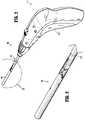
- FIG. 3is an enlarged view of the indicated area of detail of FIG. 2 ;
- FIG. 4is a perspective view of a distal portion of an elongated portion of the surgical device of FIGS. 1-3 ;
- FIGS. 5-8illustrate various types of needles and sutures in accordance with embodiments of the present disclosure
- FIGS. 9-20illustrate various embodiments showing a needle engaged with a suture in accordance with embodiments of the present disclosure
- FIG. 21is a perspective view of portions of an end effector in accordance with embodiments of the present disclosure.
- FIG. 22is an assembly view of the end effector of FIG. 21 ;
- FIG. 23is a cross-sectional view of a portion of the end effector of FIGS. 21 and 22 ;
- FIG. 24is a perspective view of a portion of the end effector of FIGS. 21-23 ;
- FIG. 25is a perspective view of portions of the end effector of FIGS. 21-24 ;
- FIG. 26is an enlarged view of the area of detail indicated in FIG. 25 ;
- FIG. 27is an enlarged view of the area of detail indicated in FIG. 25 ;
- FIG. 28is a perspective view of portions of the end effector of FIGS. 21-27 ;
- FIG. 29is a perspective view of the needle of FIG. 28 ;
- FIG. 30is a perspective view of portions of the end effector of FIGS. 21-27 and with a needle in an advanced position;
- FIG. 31is a perspective view of portions of the end effector of FIGS. 21-30 ;
- FIG. 32is an enlarged view of the area of detail indicated in FIG. 31 ;
- FIG. 33is an enlarged view of the area of detail indicated in FIG. 31 ;
- FIG. 34is a perspective view of an end effector in accordance with embodiments of the present disclosure.
- FIGS. 35 and 36are cut-away views of portions of the end effector of FIG. 34 ;
- FIG. 37is an assembly view of the end effector of FIGS. 34-36 ;
- FIG. 38is a perspective view of an end effector in accordance with embodiments of the present disclosure.
- FIG. 39is a cross-sectional view of the end effector of FIG. 38 ;
- FIG. 40is an assembly view of the end effector of FIGS. 38-39 ;
- FIG. 41is a cross-sectional view of the end effector of FIGS. 38-40 illustrating a portion of a suture in an advanced position
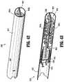
- FIG. 42is a perspective view of an end effector in accordance with embodiments of the present disclosure.
- FIG. 43is a cut-away view of a portion of the end effector of FIG. 42 ;
- FIG. 44is an assembly view of the end effector of FIGS. 42-43 ;
- FIG. 45is a cross-sectional view of the end effector of FIGS. 42-44 ;
- FIG. 46is a cross-sectional view of the end effector of FIGS. 42-45 illustrating a portion of a first barbed suture in an advanced position
- FIG. 47is a cross-sectional view of the end effector of FIGS. 42-46 illustrating the first barbed suture ejected from the end effector;
- FIG. 48is a cross-sectional view of the end effector of FIGS. 42-47 illustrating a portion of a second barbed suture in an advanced position
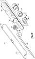
- FIG. 49is a perspective view of an end effector in accordance with embodiments of the present disclosure.
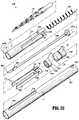
- FIG. 50is an assembly view of the end effector of FIG. 49 ;
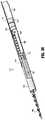
- FIG. 51is a perspective view of portions of the end effector of FIGS. 49-50 ;
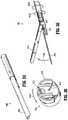
- FIG. 52is a side view of the end effector of FIGS. 49-51 illustrating a follower moving distally;
- FIG. 53is a side view of the end effector of FIGS. 49-52 illustrating the follower moving proximally;
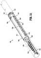
- FIG. 54is a side view of portions of an end effector in accordance with embodiments of the present disclosure.
- FIG. 55is a cross-sectional view of the end effector of FIG. 54 ;
- FIG. 56is an assembly view of the end effector of FIGS. 54-55 ;
- FIG. 57is a perspective view of portions of the end effector of FIGS. 54-56 ;
- FIG. 58is a cross-sectional view of the end effector of FIGS. 54-57 taken along line 58 - 58 of FIG. 57 ;
- FIG. 59is a side view of portions of the end effector of FIGS. 54-58 illustrating a portion of a needle in an advanced position
- FIG. 60is a cross-sectional view of the end effector of FIGS. 54-59 illustrating a portion of the needle in an advanced position
- FIG. 61is a side view of portions of the end effector of FIGS. 54-60 illustrating a portion of the needle in a further advanced position;
- FIG. 62is a cross-sectional view of the end effector of FIGS. 54-61 illustrating a portion of the needle in the further advanced position of FIG. 61 ;
- FIG. 63is a side view of portions of the end effector of FIGS. 54-62 illustrating the needle moving toward its retracted position;
- FIG. 64is a cross-sectional view of the end effector of FIGS. 54-63 illustrating the needle moving toward its retracted position;
- FIG. 65is a perspective view of an end effector in accordance with embodiments of the present disclosure.
- FIG. 66is an assembly view of the end effector of FIG. 65 ;
- FIG. 67is a perspective view of a portion of a drive shaft of the end effector of FIGS. 65-66 ;
- FIG. 68is a cross-sectional view of portions of the end effector of FIGS. 65-67 ;
- FIG. 69is a perspective view of the end effector of FIGS. 65-68 illustrating a needle in an advanced position
- FIG. 70is a perspective view of a driver in a proximal position relative to the drive shaft of the end effector of FIGS. 65-69 ;
- FIG. 71is a perspective view of the driver in a distal position relative to the drive shaft of the end effector of FIGS. 65-70 .
- distalrefers to that portion of the endoscopic surgical device that is farther from the user
- proximalrefers to that portion of the surgical device that is closer to the user.
- Non-limiting examples of surgical deviceswhich may include articulation joints according to the present disclosure include manual, mechanical and/or electromechanical surgical tack appliers (i.e., tackers), clip appliers, surgical forceps, and the like.
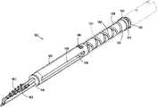
- Surgical device 100includes a handle assembly 110 , an elongated portion 120 extending distally from handle assembly 110 , an end effector 130 disposed in mechanical cooperation (e.g., releasably engaged) with a distal portion of elongated portion 120 , and a drive rod 150 disposed at least partially within elongated portion 120 and configured to engage (e.g., releasably engage) end effector 130 .
- FIGS. 1-3illustrate a general end effector 130 ; various other end effectors are shown and described throughout this application and are configured for use with surgical device 100 .
- end effector 130is a separable component that is able to be used with a surgical instrument (e.g., a surgical fixation device handle). After its use (e.g., after one or more barbed sutures are released therefrom), the end effector 130 can be removed from the remainder of the surgical instrument, and a new or reloaded end effector 130 can then engage the surgical instrument and be used.
- a surgical instrumente.g., a surgical fixation device handle
- Handle assembly 110includes a trigger or an actuator 112 (e.g., button, switch, etc.) thereon.
- actuator 112e.g., button, switch, etc.
- actuation of actuator 112results in rotation of drive rod 150 , e.g., in the general direction of arrow “A” in FIG. 4 .
- surgical device 100can transfer the movement caused by actuation of actuator 112 to rotation of drive rod 150 , such as those disclosed in U.S. patent application Ser. No. 15/049,511, filed on Feb. 22, 2016, the entire contents of which are hereby incorporated by reference herein.
- end effectors of the present disclosureare usable to advance at least a portion of a needle and/or at least a portion of a suture (e.g., a barbed suture) or other fixation device into tissue and/or mesh, for instance.
- a suturee.g., a barbed suture
- An example of a disclosed use of the end effectorsrelates to positioning and/or fixation of laparoscopic ventral mesh.
- stay-suturesare typically tied to the corners and/or cardinal points by surgeons.
- the mesh and suturesare then rolled and introduced through the trocar and into the laparoscopic working space.
- the meshis then unrolled, and positioned into place.
- the sutureshave needles attached, care must be taken during rolling, insertion, unrolling and positioning to help ensure the needle points do not damage the mesh (especially if the mesh includes an adhesion barrier layer) or to injure the patient or clinician.
- the stay-suturesare delivered across the abdominal wall (either from the inside toward the outside using an attached needle, or from the outside toward the inside using a suture passer introduced from outside the abdominal wall to grasp and pull the suture from the laparoscopic working space).
- the cliniciancan finish fixating the mesh to the abdominal wall with a separate fixation device, such as a surgical tack applier.
- the various end effectors disclosed hereinhelp standardize surgical procedures (e.g., positioning and/or fixation of laparoscopic ventral mesh) and reduce the number of steps and time required to fixate the mesh with stay-sutures.
- the needle assemblies of the present disclosureallow a surgeon to introduce and pass a stay-suture through the implant and abdominal wall without the need to pre-attach the stay-sutures to needles, and without the risk of accidental needle sticks.
- the disclosed end effectorscan used as a reload for use with standard surgical device handles to minimize the number of surgical devices (and the expense) needed for related surgical procedures.
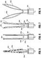
- FIG. 5illustrates a single needle 3000 a extending from a needle block 3002 , and a barbed suture 3010 a operatively engaged (e.g., releasably engaged) therewith such that needle 3000 a and barbed suture 3010 a are insertable into an implant/tissue, and barbed suture 3010 a remains in engagement with the implant/tissue when needle 3000 a is retracted.
- a pledget 3003 ais also included adjacent proximal portions of needle 3000 a and barbed suture 3010 a , which may releasably hold barbed suture 3010 a , and which may act as a stop to help limit the distal advancement of barbed suture 3010 a into the implant/tissue.
- a distal portion of barbed suture 3010 amay be bent into a hollow cavity at a distal portion of needle 3000 a to help releasably retain barbed suture 3010 a in engagement with needle 3000 a .
- FIG. 6illustrates a pair of needles 3000 b disposed in a parallel relationship extending from needle block 3002 , and a suture 3010 b supported between needles 3000 b .
- Each needle of pair of needles 3000 bextends distally from needle block 3002 in a direction that is perpendicular to a distal face 3002 b of needle block 3002 (e.g., parallel to a longitudinal axis defined by an elongated portion of surgical device 100 engaged with needle block 3002 ).
- Pair of needles 3000 bis sufficiently sturdy to support suture 3010 b therebetween.
- a distal portion of suture 3010 bmay be bent into a hollow cavity at a distal portion of needle 3000 b to help releasably retain suture 3010 b in engagement with needles 3000 b . It is envisioned that an adhesive is used to temporarily retain suture 3010 b in the illustrated position. In use, at least a portion of needles 3000 b and suture 3010 b are inserted into/through an implant/tissue to emplace suture 3010 b through the implant, for example. Suture 3010 b remains emplaced through the implant up retraction of needles 3000 b .
- FIG. 7illustrates a pair of needles 3000 c disposed in a bowed relationship extending from needle block 3002 , and a suture 3010 c supported between needles 3000 c .
- Needles 3000 cextend radially outward from each other, such that distal ends 3002 c of needles 3000 c are farther apart than proximal ends 3004 c of needles 3000 c .
- Pair of needles 3000 cis sufficiently sturdy to support suture 3010 c therebetween.
- a distal portion of suture 3010 cmay be bent into a hollow cavity at a distal portion of needle 3000 c to help releasably retain suture 3010 c in engagement with needles 3000 c . It is envisioned that an adhesive is used to temporarily retain suture 3010 c in the illustrated position.
- FIG. 8illustrates a pair of needles 3000 d extending in an arcuate manner from needle block 3002 , and supporting a suture 3010 d at least partially therebetween. Further, distal portions of suture 3010 d are engaged with distal portions of needles 3000 d .
- a distal portion of suture 3010 dmay be bent into a hollow cavity at a distal portion of needle 3000 d to help releasably retain suture 3010 d in engagement with needles 3000 d . It is envisioned that an adhesive is used to temporarily retain suture 3010 d in the illustrated position. Pair of needles 3000 d may be used when a clinician desires to secure a relatively wide portion of an implant or tissue, as the distal tips of needles 3000 d are positioned far away from each other, with respect to pair of needles 3000 b and 3000 c . It is envisioned that needles 3000 a , 3000 b , 3000 c and 3000 d are made from a shape memory material, such as nitinol.
- FIGS. 9-20Several different ways of coupling needles with suture are usable with embodiments of end effectors disclosed herein and are illustrated in FIGS. 9-20 .
- a needle 4010is shown including a flange 4012 projecting from a recess 4014 within a shaft of needle 4010 .
- a distal end of flange 4012may be able to move, flex or pivot away from recess 4014 .
- a barbed suture 4000is releasably held by flange 4012 .
- distal advancement of needle 4010 towards (e.g., into) tissuecauses a corresponding distal advancement of barbed suture 4000 .
- flange 4012moves over or releases barbed suture 4000 , thus leaving barbed suture 4000 within tissue, for example.
- a needle 4020is shown including an actuation suture 4022 extending through needle 4020 between a recess 4024 within a shaft of needle 4020 and a proximal opening 4026 of needle 4020 .
- a distal portion of actuation suture 4022releasably holds barbed suture 4000 .
- distal advancement of needle 4020 towards (e.g., into) tissuecauses a corresponding distal advancement of barbed suture 4000 .
- actuation suture 4022When actuation suture 4022 is moved proximally or retracted in the general direction of arrow “NTA,” distal portion of actuation suture 4022 moves in the general direction of arrow “NTB” or releases barbed suture 4000 , thus leaving barbed suture 4000 within tissue, for example. It is envisioned that a proximal portion of actuation suture 4022 is engaged with an appropriate anchor portion of an end effector such that advancement of needle 4020 moves needle 4020 away from the anchor portion of the end effector, which causes a relative retraction of actuation suture 4022 .
- a needle 4030including a suture 4002 engaged with a cavity 4032 of needle 4030 .
- Cavity 4032 of needle 4030includes a first, proximal portion 4032 a and a second, distal portion 4032 b .
- distal portion 4032 b of cavity 4032is deeper than proximal portion 4032 a of cavity 4032 .
- Distal portion 4032 b of cavity 4032is configured to releasably engage an enlarged or ball portion 4002 a of suture 4002
- proximal portion 4032 a of cavity 4032is configured to releasably engage a body portion 4002 b of suture 4002 .
- distal advancement of needle 4030 towards (e.g., into) tissuecauses a corresponding distal advancement of suture 4002 .
- suture 4002is able to slide in the general direction of arrow “NTA” relative to needle 4030 , thus leaving suture 4002 within tissue, for example.
- a needle 4040is shown including a proximal portion 4040 a and a distal portion 4040 b .
- Proximal portion 4040 a and distal portion 4040 b of needle 4040are releasably engaged with each other. Accordingly, moving proximal portion 4040 a proximally with respect to distal portion 4040 b , for example, can separate the two portions of needle 4040 .
- a suture 4004is engaged with a distal part of distal portion 4040 b of needle 4040 . For example, a portion of suture 4004 is disposed within a cavity 4042 of distal portion 4040 b of needle 4040 .
- distal advancement of needle 4040 towards (e.g., into) tissuecauses a corresponding distal advancement of suture 4004 .
- proximal portion 4040 a of needle 4040is moved proximally or retracted, distal portion 4040 b of needle 4040 separates from proximal portion 4040 a , which results in distal portion 4040 b of needle 4040 and portions of suture 4004 remaining in tissue.
- a needle 4050is shown including an angled axial cut 4052 disposed therein.
- Angled axial cut 4052 of needle 4050is configured to frictionally and releasably hold a portion of suture 4004 therein.
- distal advancement of needle 4050 towards (e.g., into) tissuecauses a corresponding distal advancement of suture 4004 .
- portions of suture 4004release from angled axial cut 4052 and remain within tissue, for example. It is envisioned that needle 4050 may be manufactured using an angled mill.
- a needle 4060is shown including a perpendicular axial cut 4062 disposed therein.
- Perpendicular axial cut 4062 of needle 4060is configured to frictionally and releasably hold a portion of suture 4004 therein.
- distal advancement of needle 4060 towards (e.g., into) tissuecauses a corresponding distal advancement of suture 4004 .
- portions of suture 4004release from perpendicular axial cut 4062 and remain within tissue, for example. It is envisioned that needle 4060 may be manufactured using a cut off wheel.
- a needle 4070is shown including a lateral aperture 4072 disposed therethrough.
- Lateral aperture 4072 of needle 4070is configured to allow a portion of suture 4004 to be threaded therethrough.
- distal advancement of needle 4070 towards (e.g., into) tissuecauses a corresponding distal advancement of suture 4004 .
- portions of suture 4004are removed from lateral aperture 4072 and remain within tissue, for example. It is envisioned that a pin or wire travels through needle 4070 to sever suture 4004 .
- a needle 4080is shown including a slotted tip 4082 .
- Slotted tip 4082 of needle 4080is configured to frictionally and releasably hold a portion of suture 4004 ( FIG. 19 ) or multiple sutures ( FIG. 20 ) therein.
- distal advancement of needle 4080 towards (e.g., into) tissuecauses a corresponding distal advancement of suture(s) 4004 .
- portions of suture(s) 4004are removed from slotted tip 4082 and remain within tissue, for example.
- End effector 1000is configured for use in connection with surgical device 100 .
- end effector 1000is configured to prevent unintentional contact with a needle and/or a barbed suture within or extending distally from its outer tube. While FIGS. 21-33 illustrate a particular type of barbed suture 1002 and a particular type of needle 1006 , end effector 1000 may be used with different types of sutures and/or needles.
- end effector 1000includes a cover 1010 , a first biasing element or spring 1020 , a clevis 1030 , a clutch 1040 , a drive element 1050 , a second biasing element or spring 1060 ( FIG. 22 ), and an outer tube 1070 .
- Cover 1010 of end effector 1000includes a cylindrical body portion 1012 , a pair of arms 1014 extending proximally from body portion 1012 , a lip 1016 extending radially inward from a proximal portion of each arm 1014 , and a tab 1018 extending radially outward from a proximal portion of one the arms 1014 .
- Clevis 1030 of end effector 1000includes a body portion 1032 , a pair of arms 1034 extending distally from body portion 1032 , a flange 1036 extending radially outward from body portion 1032 , and a plurality of teeth 1038 disposed on a proximal end of body portion 1032 .
- First biasing element 1020is positioned between arms 1034 of clevis 1030 and arms 1014 of cover 1010 .
- Body portion 1032 of clevis 1030engages a proximal end of first biasing element 1020 ; lips 1016 of cover 1010 engage a distal end of first biasing element 1020 .
- a proximal portion 1007 of needle 1006is positioned radially inward of body portion 1032 of clevis 1030 . Further, flat portions 1007 a (see FIG. 28 ) of proximal portion 1007 of needle 1006 engage corresponding flat portions 1037 of body portion 1032 of clevis 1030 , thus limiting or preventing rotation therebetween. Needle 1006 also includes a distal tip 1008 and a hook 1009 . Distal tip 1008 of needle 1006 is configured to pierce tissue, and hook 1009 of needle 1006 is configured to engage a portion of barbed suture 1002 .
- Clutch 1040 of end effector 1000includes a body portion 1042 , a plurality of teeth 1044 disposed on a distal end of body portion 1042 , and a proximal surface 1046 .
- Teeth 1044 of clutch 1040are configured to engage teeth 1038 of clevis 1030 .
- Drive element 1050 of end effector 1000is mechanically engaged (e.g., operatively coupled, directly affixed, etc.) to drive rod 150 of surgical device 100 of the present disclosure.
- Drive element 1050includes a proximal end 1052 , a distal end 1054 , and a groove 1056 .
- Groove 1056 of drive element 1050is configured to engage a shipping wedge (not shown) to help lock drive element 1050 in place with respect to outer tube 1070 , for example.
- Proximal end 1052 of drive element 1050is configured to engage the drive rod.
- Distal end 1054 of drive element 1050is mechanically engaged with second biasing element 1060 .
- Proximal surface 1046 of clutch 1040is positioned to engage second biasing element 1060 . That is, second biasing element 1060 is positioned between proximal surface 1046 of clutch 1040 and distal end 1054 of drive element 1050 .
- Outer tube 1070 of end effector 1000includes a proximal notch 1072 , a cutout 1074 , and a longitudinal groove 1076 having an angled slot 1078 extending therefrom.
- Outer tube 1070is configured for positioning radially outward of, and to at least partially contain, at least portions of barbed suture 1002 , needle 1006 , cover 1010 , first biasing element 1020 , clevis 1030 , clutch 1040 , drive element 1050 , and second biasing element 1060 .
- proximal notch 1072is longitudinally aligned with groove 1056 of drive element 1050 such that a shipping wedge (not shown) can extend through proximal notch 1072 and into engagement with groove 1056 .
- the engagement between drive element 1050 , second biasing element 1060 , clutch 1040 , and clevis 1030is also shown in FIG. 23 .
- second biasing element 1060is disposed between drive element 1050 and clutch 1040 , thus transferring rotational movement from drive element 1050 (and drive rod 150 , as discussed above) to clutch 1040 .
- second biasing element 1060enacts a distal force onto clutch 1040 to help maintain engagement between teeth 1044 of clutch 1040 and teeth 1038 of clevis 1030 . Accordingly, rotation of clutch 1040 results in a corresponding rotation of clevis 1030 .
- tab 1018 of cover 1010 of end effector 1000is disposed within angled slot 1078 of longitudinal groove 1076 of outer tube 1070 .
- the engagement between tab 1018 and angled slot 1078prevents cover 1010 from distally advancing with respect to outer tube 1070 .
- cover 1010In this position, cover 1010 is in its distal-most position where it radially surrounds distal tip 1008 of needle 1006 and barbed suture 1002 .
- the drive rod 150rotates, as discussed above. Rotation of the drive rod results in a corresponding rotation of drive element 1050 , clutch 1040 , and clevis 1030 .
- a predetermined amount of rotation (e.g., about) 90°) of clevis 1030causes flange 1036 of clevis 1030 to rotate in the general direction of arrow “FLA” from a first position within cutout 1074 of outer tube 1070 , to a second position where flange 1036 engages a lateral wall 1074 a of cutout 1074 of outer tube 1070 (see FIG. 27 ).
- a userpresses a distal tip of surgical device 100 against tissue and/or mesh to emplace barbed suture 1002 at least partially therein and/or therethrough. More particularly, the user pushes a distal edge 1010 a of cover 1010 against the tissue/mesh, which causes cover 1010 to move proximally with respect to outer tube 1070 against the bias of first biasing element 1020 . As cover 1010 moves proximally, tab 1018 of cover 1010 travels proximally within longitudinal groove 1076 of outer tube 1070 .
- cover 1010exposes barbed suture 1002 and distal tip 1008 of needle 1006 , at least portions of which extend distally beyond outer tube 1070 , and enables barbed suture 1002 and distal tip 1008 to penetrate the tissue/mesh.
- first biasing element 1020urges cover 1010 distally with respect to outer tube 1070 .
- Cover 1010continues to move distally while tab 1018 of cover 1010 travels within longitudinal groove 1076 of outer tube 1070 until tab 1018 contacts a distal edge 1076 a of longitudinal groove 1076 , preventing further distal movement of cover 1010 with respect to outer tube 1070 (see FIGS. 31 and 32 ).
- cover 1010contacts distal edge 1076 a of longitudinal groove 1076 , at least one proximal finger 1019 of cover 1010 enters an aperture 1071 of outer tube 1070 (e.g., in response to a radial outward bias of arms 1014 ), thus effectively locking the longitudinal position of cover 1010 with respect to outer tube 1070 (see FIGS. 31 and 33 ).
- a safety cover assembly 2800 for use with various end effectors disclosed hereinis shown.
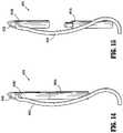
- a cover 2810 of safety cover assembly 2800is configured to pivot between a first position where safety cover 2800 helps prevent unintentional contact with a needle 2806 ( FIG. 34 ), and a second position where safety cover 2800 allows needle 2806 to be driven into tissue ( FIG. 35 ).
- safety cover assembly 2800includes cover 2810 , a drive member 2820 , a biasing member 2830 , a gear 2840 , a clutch 2850 , and an outer tube 2870 .
- Cover 2810includes a proximal lip 2812 , and an angled blocking portion 2814 ( FIG. 36 ).
- Proximal lip 2812is configured to pivotably engage a distal finger 2872 of outer tube 2870 to facilitate pivotal movement therebetween.
- Blocking portion 2814 of cover 2810is configured to selectively engage a portion of needle 2806 and/or clutch 2850 . The engagement between blocking portion 2814 and needle 2806 and/or clutch 2850 restricts the biasing force supplied by biasing member 2830 .
- Biasing member 2830 of cover assembly 2800includes a first portion 2832 engaged with (e.g., affixed to) a proximal portion of needle 2086 , and a second portion 2834 engaged with (e.g., affixed to) a proximal portion of cover 2810 .
- Biasing member 2830is configured to bias cover 2810 away from needle 2806 toward its second position ( FIG. 35 ). As noted above, the engagement between blocking portion 2814 of cover 2810 and needle 2806 and/or clutch 2850 resists the biasing force supplied by biasing member 2830 .
- Drive member 2820 , gear 2840 , and clutch 2850 of cover assembly 2800are disposed radially within outer tube 2870 .
- Drive member 2820is mechanically engaged (e.g., operatively coupled, directly affixed, etc.) to drive rod 150 of surgical device 100 of the present disclosure. Accordingly, rotation of the drive rod 150 in the general direction of arrow “FSA” results in a corresponding rotation of drive member 2820 .
- drive member 2820is configured to engage gear 2840 such that rotation of drive member 2820 in the general direction of arrow “FSA” causes a corresponding rotation of gear 2840 in the general direction of arrow “FSA.”
- gear 2840is configured to engage clutch 2850 such that rotation of gear 2840 in the general direction of arrow “FSA” causes a corresponding rotation of clutch 2850 .
- clutch 2850 of cover assembly 2800is configured to engage a portion of cover 2810 , such that rotation of clutch 2850 in the general direction of arrow “FSA” causes a corresponding rotation of cover 2810 in the general direction of arrow “FSA.”
- rotation of cover 2810 in the general direction of arrow “FSA”causes blocking portion 2814 of cover 2810 to rotate with respect to needle 2806 , such that blocking portion 2814 no longer resists the force exerted by biasing member 2830 onto cover 2810 .
- proximal teeth 2852 of clutch 2850which mate with distal teeth 2842 of gear 2840 , are configured to skip following additional rotation of gear 2840 after cover 2810 moves toward its second position.
- cover 2810When cover 2810 is in its second position, needle 2806 is exposed and is able to be driven into tissue, for example. If a user desires to move cover 2810 back toward its first position, the user may use a secondary instrument or the user's hand, to pivot cover 2810 toward its first position against the bias of biasing member 2830 .
- the cover 2810can be rotated in the general direction of arrow “FSC” ( FIG. 35 ) such that blocking portion 2814 engages needle 2806 and resists the force exerted by biasing member 2830 .
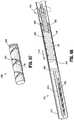
- End effector 1600includes a barbed suture 1602 at least partially therein, and is configured for use in connection with surgical device 100 . Additionally, end effector 1600 is configured for use with a separate instrument (e.g., a needle suture passer) to drive and/or implant the suture in tissue. Generally, end effector 1600 is configured to advance barbed suture 1602 distally, such that a suture 1603 of barbed suture 1602 is graspable by a user. While FIGS. 38-41 illustrate a particular type of barbed suture 1602 , end effector 1600 may be used with different types of sutures.
- a separate instrumente.g., a needle suture passer
- end effector 1600includes a drive assembly 1610 , a drive plate 1620 , a helix or coil assembly 1630 , an ejector 1640 , a divider 1650 , a pair of rings 1665 , and an outer tube 1670 .
- Drive assembly 1610 of end effector 1600is mechanically engaged (e.g., operatively coupled, directly affixed, etc.) to drive rod 150 of surgical device 100 of the present disclosure.
- Drive assembly 1610includes a body portion 1612 , and a pair of arms 1614 extending distally from body portion 1612 and defining a cavity 1616 therebetween.
- Drive plate 1620 of end effector 1600includes a disc-like body 1622 , a first flange 1624 extending radially outward from body 1622 , and a second flange 1626 extending radially outward from body 1622 .
- First flange 1624 of drive plate 1620includes a distally-facing ledge 1625 configured for engaging helix or coil assembly 1630 .
- Second flange 1626 of drive plate 1620includes a proximally-facing ledge 1627 configured for engaging helix or coil assembly 1630 of end effector 1600 .
- Body 1622 of drive plate 1620is positioned within cavity 1616 of drive assembly 1610 , and portions of first flange 1624 and second flange 1626 extend between arms 1614 of drive assembly 1610 .
- Helix or coil assembly 1630 of end effector 1600is disposed radially within outer tube 1670 , and radially outward of arms 1614 of drive assembly 1610 .
- Helix or coil assembly 1630is stationary with respect to outer tube 1670 , and is configured to engage drive plate 1620 , such that drive plate 1620 can move longitudinally and rotationally within outer tube 1670 and with respect to outer tube 1670 .
- Ejector 1640 of end effector 1600is disposed within outer tube 1670 and is longitudinally translatable with respect to outer tube 1670 .
- Ejector 1640includes a proximal portion 1642 having a slit 1644 extending partially therethrough, and an arm 1646 extending from proximal portion 1642 .
- a proximal face 1643 of proximal portion 1642 of ejector 1640is positioned for engagement by drive plate 1620 . It is envisioned that proximal face 1643 includes a finger extending proximally therefrom for engagement with a detent or aperture within a distal face of drive plate 1620 .
- Arm 1646 of ejector 1640is configured to help prevent suture 1603 disposed adjacent thereto from engaging outer tube 1670 and possibly getting stuck thereon.
- a distal end of arm 1646includes a suture guide 1648 configured to help guide and/or position suture 1603 .
- Divider 1650 of end effector 1600includes a longitudinal slot 1651 extending partially along a length of divider 1650 .
- a proximal portion of divider 1650is positioned within slit 1644 of ejector 1640 .
- Divider 1650is configured to create two cavities—a first cavity 1652 disposed between arm 1646 of ejector 1640 and divider 1650 , and a second cavity 1654 disposed between outer tube 1670 and divider 1650 (see FIGS. 39 and 41 ).
- First cavity 1652is configured to releasably house a portion (e.g. a majority) of suture 1603
- second cavity 1654is configured to releasably house a barbed portion 1604 of barbed suture 1602 therein.
- Rings 1665(e.g., O-rings) of end effector 1600 are positioned radially outward of body portion 1612 of drive assembly 1610 . Rings 1665 help maintain appropriate spacing between drive assembly 1610 and outer tube 1670 , and help facilitate rotation of drive assembly 1610 with respect to outer tube 1670 .
- Outer tube 1670 of end effector 1600is positioned radially outward of at least portions of barbed suture 1602 , drive assembly 1610 , drive plate 1620 , helix or coil assembly 1630 , ejector 1640 , divider 1650 , and rings 1665 .
- drive rod 150rotates, as discussed above.
- rotation of the drive rod 150results in a corresponding rotation of drive assembly 1610 in the general direction of arrow “SCDA” ( FIG. 41 ) with respect to outer tube 1670 .
- Rotation of drive assembly 1610results in a corresponding rotation of drive plate 1620 due to the engagement between arms 1614 of drive assembly 1610 , and first flange 1624 and second flange 1626 of drive plate 1620 .
- end effector 1600is configured for use with a separate instrument (e.g., a needle suture passer) to drive and/or implant suture 1603 in tissue.
- a separate instrumente.g., a needle suture passer
- End effector 1800includes two barbed sutures 1802 a , 1802 b at least partially therein, and is configured for use in connection with surgical device 100 . Additionally, end effector 1800 is configured for use with a separate instrument (e.g., a needle suture passer) to drive and/or implant the sutures in tissue. Generally, end effector 1800 is configured to advance barbed sutures 1802 a , 1802 b distally, such that portions of a suture 1803 a , 1803 b of barbed sutures 1802 a , 1802 b , respectively, are graspable by a user. While FIGS. 42-48 illustrate a particular type of barbed suture 1802 a , 1802 b , end effector 1800 may be used with different types of sutures.
- end effector 1800includes a drive assembly 1810 , a drive plate 1820 , a helix or coil assembly 1830 , an ejector 1840 , a divider 1850 , a pair of rings 1865 , and an outer tube 1870 .
- Drive assembly 1810 of end effector 1800is mechanically engaged (e.g., operatively coupled, directly affixed, etc.) to drive rod 150 of surgical device 100 of the present disclosure.
- Drive assembly 1810includes a body portion 1812 , and a pair of arms 1814 extending distally from body portion 1812 and defining a cavity 1816 therebetween.
- Drive plate 1820 of end effector 1800includes a disc-like body 1822 , a first flange 1824 extending radially outward from body 1822 , and a second flange 1826 extending radially outward from body 1822 .
- First flange 1824 of drive plate 1820includes a distally-facing ledge 1825 configured for engaging helix or coil assembly 1830 .
- Second flange 1826 of drive plate 1820includes a proximally-facing ledge 1827 configured for engaging helix or coil assembly 1830 .
- Body 1822 of drive plate 1820is positioned within cavity 1816 of drive assembly 1810 , and portions of first flange 1824 and second flange 1826 extend between arms 1814 of drive assembly 1810 .
- Helix or coil assembly 1830 of end effector 1800is disposed radially within outer tube 1870 , and radially outward of arms 1814 of drive assembly 1810 .
- Helix or coil assembly 1830is stationary with respect to outer tube 1870 , and is configured to engage drive plate 1820 , such that drive plate 1820 can move longitudinally and rotationally within outer tube 1870 and with respect to outer tube 1870 .
- Ejector 1840 of end effector 1800is disposed within outer tube 1870 and is longitudinally translatable with respect to outer tube 1870 .
- Ejector 1840includes a proximal portion 1842 , a first arm 1844 extending distally from proximal portion 1842 , and a second arm 1846 extending distally from proximal portion 1842 .
- First arm 1844 of ejector 1840extends farther distally than second arm 1846 .
- a proximal face 1843 of proximal portion 1842 of ejector 1840is positioned for engagement by drive plate 1820 .
- proximal face 1843includes a finger extending proximally therefrom for engagement with a detent or aperture within a distal face of drive plate 1820 .
- a distal face 1845 of first arm 1844 of ejector 1840is configured to move into engagement with a proximal portion of barbed suture 1802 a
- a distal face 1847 of second arm 1846is configured to move into engagement with a proximal portion of barbed suture 1802 b.
- Divider 1850 of end effector 1800includes a longitudinal slot 1851 extending partially along a length of divider 1850 .
- Divider 1850is positioned within a distal portion of outer tube 1870 , and is frictionally engaged with outer tube 1870 , which prevents or minimizes movement of divider 1850 with respect to outer tube 1870 .
- Divider 1850is configured to create two cavities—a first cavity 1852 disposed distally of first arm 1844 of ejector 1840 and between divider 1850 and outer tube 1870 , and a second cavity 1854 disposed distally of second arm 1846 of ejector 1840 and between divider 1850 and outer tube 1870 (see FIGS. 43 and 45 ).
- First cavity 1852 of divider 1850is configured to releasably house barbed suture 1802 a therein
- second cavity 1854 of divider 1850is configured to releasably house barbed suture 1802 b therein.
- Rings 1865(e.g., O-rings) of end effector 1800 are positioned radially outward of body portion 1812 of drive assembly 1810 . Rings 1865 help maintain appropriate spacing between drive assembly 1810 and outer tube 1870 , and help facilitate rotation of drive assembly 1810 with respect to outer tube 1870 .
- Outer tube 1870 of end effector 1800is positioned radially outward of at least portions of barbed sutures 1802 a , 1802 b , drive assembly 1810 , drive plate 1820 , helix or coil assembly 1830 , ejector 1840 , divider 1850 , and rings 1865 .
- drive rod 150rotates, as discussed above.
- rotation of the drive rod 150results in a corresponding rotation of drive assembly 1810 in the general direction of arrow “TCA” ( FIG. 46 ) with respect to outer tube 1870 .
- Rotation of drive assembly 1810results in a corresponding rotation of drive plate 1820 due to the engagement between arms 1814 of drive assembly 1810 , and first flange 1824 and second flange 1826 of drive plate 1820 .
- drive plate 1820moves longitudinally in the general direction of arrow “TCB” ( FIG. 46 ) with respect to outer tube 1870 .
- the distal longitudinal movement of drive plate 1820causes a corresponding distal translation of ejector 1840 due to the engagement between drive plate 1820 and proximal face 1843 of ejector 1840 .
- ejector 1840As ejector 1840 translates distally, ejector 1840 pushes barbed suture 1802 a distally such that a portion of suture 1803 a is moved distally beyond a distal end of outer tube 1870 and is thus graspable by a user (see FIGS. 46 and 47 ).
- drive rod 150rotates again. Rotation of the drive rod 150 results in an additional rotation of drive assembly 1810 in the general direction of arrow “TCA,” a corresponding rotation of drive plate 1820 , distal longitudinal movement of drive plate 1820 , and a corresponding distal longitudinal movement of ejector 1840 in the general direction of “TCB” ( FIG. 48 ). As ejector 1840 moves distally, ejector 1840 pushes barbed suture 1802 b such that a portion of suture 1803 b is moved distally beyond a distal end of outer tube 1870 and is thus graspable by a user (see FIG. 48 ). As noted above, end effector 1800 is configured for use with a separate instrument (e.g., a needle suture passer) to drive and/or implant sutures 1803 a , 1803 b in tissue.
- a separate instrumente.g., a needle suture passer
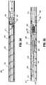
- End effector 1900includes a barbed suture 1902 and a needle 1906 at least partially therein, and is configured for use in connection with surgical device 100 .
- end effector 1900is configured to advance needle 1906 and to eject barbed suture 1902 towards tissue. While FIGS. 49-53 illustrate a particular type of barbed suture 1902 and needle 1906 , end effector 1900 may be used with different types of sutures and needles.
- end effector 1900includes a drive ring 1910 , a drive assembly or drive shaft 1920 , a driver 1930 , a needle assembly or cap 1940 , and an outer tube 1970 .
- Drive ring 1910 of end effector 1900is mechanically engaged (e.g., operatively coupled, directly affixed, etc.) to drive rod 150 of surgical device 100 of the present disclosure.
- Drive ring 1910is ring-like and is configured to non-rotationally engage a proximal portion of drive shaft 1920 , such that rotation of drive ring 1910 causes a corresponding rotation of drive shaft 1920 .
- Drive shaft 1920 of end effector 1900includes an elongated cylindrical body portion and is disposed in mechanical engagement with drive ring 1910 .
- Drive shaft 1920includes a proximal groove 1922 , a first helical groove 1924 and a second helical groove 1926 .
- First helical groove 1924 and second helical groove 1926encircle at least a portion of drive shaft 1920 , and are interconnected at their proximal ends and their distal ends.
- Proximal groove 1922is configured to rotatably engage a first pin 1950 and a second pin 1952 , such that drive shaft 1920 is rotatable with respect to first pin 1950 and second pin 1952 .
- Drive shaft 1920is fixed from longitudinal movement with respect to first pin 1950 and second pin 1952 .
- first pin 1950 and second pin 1952extend at least partially through apertures 1971 in outer tube 1970 .
- drive shaft 1920is fixed from longitudinal movement with respect to outer tube 1970 .
- First helical groove 1924 and second helical groove 1926 of drive shaft 1920are each configured to rotatably engage a follower 1960 . More particularly, follower 1960 engages or fits at least partially within a portion of first helical groove 1924 to cause follower 1960 to move distally with respect to drive shaft 1920 when drive shaft 1920 rotates in a first direction (e.g., upon initial actuation of a trigger).
- follower 1960engages or fits at least partially within a portion of second helical groove 1926 to cause follower 1960 to move proximally with respect to drive shaft 1920 when drive shaft 1920 rotates in a second direction (e.g., upon a subsequent actuation of the trigger).
- Driver 1930 of end effector 1900is a hollow cylinder and is configured to be positioned radially outward of at least portions of drive shaft 1920 .
- Driver 1930includes a proximal aperture 1932 , and a pair of longitudinal slots 1934 extending along a majority of a length of driver 1930 .
- Proximal aperture 1932 of driver 1930is configured to allow follower 1960 to pass at least partially therethrough.
- proximal aperture 1932is generally bow-tie shaped, which allows follower 1960 to rotate about an axis “DHP” defined therethrough, with respect to aperture 1932 .
- Longitudinal slots 1934are configured to allow a third pin 1935 to pass therethrough, such that third pin 1935 extends from a first longitudinal slot 1934 a , through the hollow center of driver 1930 , and through a second longitudinal slot 1934 b .
- Third pin 1935is positioned distally of drive shaft 1920 .
- Cap 1940 of end effector 1900is configured to engage (e.g., is affixed to) a distal end of driver 1930 and is configured to engage (e.g., is affixed to) a proximal end of needle 1906 .
- Cap 1940includes a needle-securing portion 1942 to help engage needle 1906 .
- Needle-securing portion 1942 of cap 1940is offset from a radial center of cap 1940 .
- cap 1940includes a proximal flange 1944 , which is configured to fit radially within driver 1930 , to help secure the connection therebetween.
- Outer tube 1970 of end effector 1900is positioned radially outward of at least portions of barbed suture 1902 , needle 1906 , drive ring 1910 , drive shaft 1920 , driver 1930 , and cap 1940 .
- Outer tube 1970includes a longitudinal slot 1972 extending along a portion of its length. Longitudinal slot 1972 of outer tube 1970 is configured to allow a pin portion 1962 of follower 1960 to extend therethrough, which allows follower 1960 and driver 1930 to longitudinally translate with respect to outer tube 1970 .
- drive rod 150rotates, as discussed above.
- rotation of the drive rod 150results in a corresponding rotation of drive ring 1910 in the general direction of arrow “DHA” ( FIG. 52 ) with respect to outer tube 1970 .
- Rotation of drive ring 1910results in a corresponding rotation of drive shaft 1920 due to the engagement therebetween.
- the engagement between proximal groove 1922 of drive shaft 1920 with first pin 1950 and second pin 1952facilitates rotation of drive shaft 1920 with respect to outer tube 1970 , and restricts drive shaft 1920 from moving longitudinally with respect to outer tube 1970 .
- follower 1960engages first helical groove 1924 of drive shaft 1920 .
- follower 1960moves distally in the general direction of arrow “DHB” in response to rotation of drive ring 1910 in the general direction of arrow “DHA.”
- the engagement between pin portion 1962 of follower 1960 and longitudinal slot 1972 of outer tube 1970allows follower 1960 to move longitudinally with respect to outer tube 1970 , and restricts follower 1960 from moving rotationally with respect to outer tube 1970 .
- the distal translation of follower 1960causes a corresponding distal translation of driver 1930 with respect to outer rube 1970 due to the engagement between follower 1960 and driver 1930 .
- the engagement between third pin 1935 and longitudinal slots 1934 of driver 1930help guide the longitudinal travel of driver 1930 with respect to outer tube 1970 .
- driver 1930translates distally, cap 1940 , needle 1906 and barbed suture 1902 are pushed distally with respect to outer tube 1970 .
- needle 1906travels distally, a distal portion of needle 1906 (e.g., a distal tip 1906 a ) and barbed suture 1902 distally exit outer tube 1970 , and engages tissue/mesh, for instance.
- follower 1960When drive shaft 1920 has rotated a predetermined amount, follower 1960 continues its movement within first helical groove 1924 , and moves into a transition portion 1925 ( FIG. 50 ), which interconnects first helical groove 1924 and second helical groove 1926 . Continued rotation of drive shaft 1920 causes follower 1960 to move from transition portion 1925 and into second helical groove 1926 .
- the movement of follower 1960 from first helical groove 1924 , into transition portion 1925 , and into second helical groove 1926causes follower 1960 to rotate or pivot about axis “DHP” which extends through pin portion 1962 , and which is perpendicular to longitudinal axis “DHA,” such that follower 1960 aligns with second helical groove 1926 .
- drive ring 1910 and drive shaft 1920continue to rotate in the general direction of arrow “DHA.” Due to the engagement between follower 1960 and second helical groove 1926 , the rotation of drive shaft 1920 causes follower 1960 to move proximally in the general direction of arrow “DHC” ( FIG. 53 ). Proximal movement of follower 1960 results in a corresponding proximal movement of driver 1930 , and thus proximal movement of needle 1906 . Needle 1906 is movable proximally until its distal tip 1906 a is longitudinally aligned with or proximal of a distal end of outer tube 1970 , thereby reducing the possibility of a user unintentionally contacting needle 1906 .
- one complete actuation of the trigger of surgical device 100causes drive shaft 1920 to rotate a particular number of times (e.g., five) corresponding to follower 1960 and driver 1930 moving from their proximal-most positions to their distal-most positions (corresponding to the first two and one half rotations), and back to their proximal-most positions (corresponding to the second two and one half rotations).
- drive shaft 1920rotates a particular number of times (e.g., five) corresponding to follower 1960 and driver 1930 moving from their proximal-most positions to their distal-most positions (corresponding to the first two and one half rotations), and back to their proximal-most positions (corresponding to the second two and one half rotations).
- one complete actuation of the trigger of surgical device 100causes drive shaft 1920 to rotate a particular number of time (e.g., five) corresponding to follower 1960 and driver 1930 moving from their proximal-most positions to their distal-most positions
- a second complete actuation of the trigger of surgical device 100causes drive shaft 1920 to rotate a particular number of time (e.g., five) corresponding to follower 1960 and driver 1930 moving from their distal-most positions to their proximal-most positions.
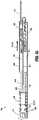
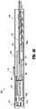
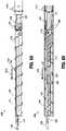
- End effector 2200is configured for use in connection with surgical device 100 .
- end effector 2200is configured to advance a needle 2206 towards tissue and to eject a barbed suture 2202 towards tissue. While FIGS. 54-64 illustrate a particular type of barbed suture 2202 and a particular type of needle 2206 , end effector 2200 may be used with different types of sutures and/or needles.
- end effector 2200includes an activation sleeve 2203 , a drive assembly 2210 , a driver 2220 , a retraction spring 2230 , a helix or coil assembly 2240 , a pair of rings 2250 , and an outer tube 2270 .
- Activation sleeve 2203 of end effector 2200is mechanically engaged (e.g., operatively coupled, directly affixed, etc.) to a drive rod assembly 2280 of the handle assembly of the surgical device 100 of the present disclosure.
- Rotation of drive rod assembly 2280 in the general direction of arrow “RTA” in FIG. 56results in a corresponding rotation of activation sleeve 2203 .
- Drive assembly 2210 of end effector 2200is mechanically and selectively engaged with activation sleeve 2203 , as discussed in further detail below. When engaged, rotation of activation sleeve 2203 in the general direction of arrow “RTA” results in a corresponding rotation of drive assembly 2210 .
- Drive assembly 2210includes a body portion 2212 and a pair of arms 2214 extending therefrom. Arms 2214 of drive assembly 2210 define a pair of slots 2216 therebetween. Slots 2216 of arms 2214 are configured to slidingly receive portions of driver 2220 of end effector 2200 .
- Needle 2206includes a distal tip 2206 a and a hook 2206 b .
- Distal tip 2206 a of needle 2206is configured to pierce tissue, and hook 2206 b is configured to engage a portion of barbed suture 2202 .
- Driver 2220 of end effector 2200includes a body portion 2222 defining a cavity 2224 therein, a proximal portion 2226 , and a threaded portion 2228 including at least one thread.
- a distal end 2223 of body portion 2222 of driver 2220is configured to contact a proximal portion of needle 2206 .
- Cavity 2224 of driver 2220is configured to releasably house a portion of barbed suture 2002 therein.
- Proximal portion 2226 of driver 2220is configured to engage a distal portion of retraction spring 2230 .
- a first thread 2228 a and a second thread 2228 b of threaded portion 2228 of driver 2220are configured to extend through respective slots 2216 of drive assembly 2210 to engage helix or coil assembly 2240 , which extends radially inward from an inner wall 2271 of outer tube 2270 .
- a distal portion of retraction spring 2230 of end effector 2200is engaged with proximal portion 2226 of driver 2220 , and a proximal portion of retraction spring 2230 is engaged with a portion of activation sleeve 2203 .
- Retraction spring 2230is configured to bias driver 2220 proximally.
- Helix or coil assembly 2240 of end effector 2200extends radially inward from inner wall 2271 of outer tube 2270 , and is stationary with respect to outer tube 2270 .
- Helix or coil assembly 2240is configured to engage thread portion 2228 of driver 2220 such that driver 2220 can move longitudinally and rotationally within outer tube 2270 and with respect to outer tube 2270 .
- Rings 2250(e.g., O-rings) of end effector 2200 are positioned radially outward of portions of activation sleeve 2230 . Rings 2250 help maintain appropriate spacing between activation sleeve 2230 and outer tube 2270 , and help facilitate rotation of activation sleeve 2230 with respect to outer tube 2270 .
- Outer tube 2270 of end effector 2200is configured for positioning radially outward of at least portions of barbed suture 2202 , needle 2206 , activation sleeve 2203 , drive assembly 2210 , driver 2220 , retraction spring 2230 and rings 2250 .
- End effector 2200also includes a ratchet mechanism 2290 .
- Ratchet mechanism 2290includes a pair of tabs 2292 a , 2292 b , which extend radially inwardly from a proximal portion of drive assembly 2210 , and a pair of engagement features 2294 a , 2294 b disposed on activation sleeve 2203 .
- Tabs 2292 a , 2292 b of ratchet mechanism 2290are configured to selectively engage engagement features 2294 a , 2294 b , respectively, as discussed in further detail below.
- drive rod 150rotates, as discussed above.
- initial rotation of the drive rod 150results in a corresponding rotation of activation sleeve 2203 , drive assembly 2210 and driver 2220 with respect to outer tube 2270 in the general direction of arrow “RTA” in FIGS. 59 and 60 .
- the engagement between tabs 2210 a of drive assembly 2210 and recesses 2203 a of activation sleeve 2203causes rotation of drive assembly 2210 in the direction of arrow “RTA” in response to rotation of activation sleeve 2203 in the direction of arrow “RTA.”
- the engagement between arms 2214 of drive assembly 2210 and threaded portion 2228 of driver 2220causes rotation of driver 2220 in the direction of arrow “RTA” in response to rotation of drive assembly 2210 in the direction of arrow “RTA.”
- the rotation of driver 2220 in the direction of arrow “RTA”causes at least a distal portion of retraction spring 2230 to rotate or wind in a corresponding fashion due to the engagement between the distal portion of retraction spring 2230 and driver 2220 .
- driver 2220due to the engagement between helix or coil assembly 2240 and threaded portion 2228 of driver 2220 , rotation of driver 2220 in the general direction of arrow “RTA” results in distal translation of driver 2200 with respect to outer tube 2270 in the general direction of arrow “RTB” in FIGS. 59 and 60 .
- Distal translation of driver 2220causes a corresponding distal translation of needle 2206 .
- distal translation of driver 2220also causes a corresponding distal translation of barbed suture 2202 due to the engagement between barbed suture 2202 and distal end 2223 of driver 2220 and/or between barbed suture 2202 and needle 2206 .
- driver 2220to rotate in the same direction (e.g., due to the engagement between threaded portion 2228 and helix or coil assembly 2240 ) and move proximally in the direction of arrow “RTD” in FIGS. 63 and 64 .
- the rotation of driver 2220 in the direction of arrow “RTC”causes a corresponding rotation of driver assembly 2210 , which results in tabs 2210 a thereof disengaging from recesses 2203 a activation sleeve 2203 ( FIG. 58 ), and which allows activation sleeve 2203 to return to its original position with respect to drive assembly 2210 .
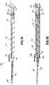
- End effector 2400includes a barbed suture 2402 and a needle 2406 at least partially therein, and is configured for use in connection with surgical device 100 .
- end effector 2400is configured to advance needle 2406 and to eject barbed suture 2402 towards tissue. While FIGS. 65-71 illustrate a particular type of barbed suture 2402 and needle 2406 , end effector 2400 may be used with different types of sutures and needles.
- end effector 2400includes a drive shaft 2420 , a driver 2430 , a cap 2440 , and an outer tube 2470 .
- Drive shaft 2420 of end effector 2400is mechanically engaged (e.g., operatively coupled, directly affixed, etc.) to drive rod 150 of surgical device 100 of the present disclosure.
- Drive shaft 2420is an elongated cylinder and includes a proximal groove 2422 , a first helical groove 2424 and a second helical groove 2426 .
- Proximal groove 2422 of drive shaft 2420is configured to rotatably engage at least one pin (not explicitly shown) that extends at least partially through outer tube 2470 , such that drive shaft 2420 is rotatable with respect to outer tube 2470 and drive shaft 2420 is fixed from longitudinal movement with respect to outer tube 2470 .
- First helical groove 2424 and second helical groove 2426 of drive shaft 2420are each configured to rotatably engage a first portion 2432 a of a follower 2432 of driver 2430 . More particularly, first portion 2432 a of follower 2432 engages or fits at least partially within a portion of first helical groove 2424 to cause follower 2432 to move distally with respect to drive shaft 2420 when drive shaft 2420 rotates in the general direction of arrow “RLA” in FIG. 68 (e.g., upon initial actuation of a trigger).
- first portion 2432 a of follower 2432engages or fits at least partially within a portion of second helical groove 2426 to cause follower 2432 to move proximally with respect to drive shaft 2420 when drive shaft 2420 rotates in the general direction of arrow “RLB” in FIG. 69 (e.g., upon a subsequent actuation of the trigger).
- Driver 2430 of end effector 2400is a generally a hollow cylinder and is configured to be positioned radially outward of at least portions of drive shaft 2420 .
- Driver 2430includes a body portion 2431 , follower 2432 disposed adjacent a proximal end thereof, and a proximal aperture 2434 .
- Follower 2432 of driver 2430is a pin-like structure including first portion 2432 a extending radially inward from body portion 2431 , and a second portion 2432 b extending radially outward from body portion 2431 .
- First portion 2432 a of follower 2432is configured to engage first helical groove 2424 and second helical groove 2426 .
- Second portion 2432 b of follower 2432is configured to extend at least partially through a longitudinal slot 2472 of outer tube 2470 .
- Proximal aperture 2434 of driver 2430is configured to allow drive shaft 2420 to pass at least partially therethrough.
- Cap 2440 of end effector 2400is configured to engage (e.g., is affixed to) a distal end of driver 2430 and is configured to engage (e.g., is affixed to) a proximal end of needle 2406 .
- Cap 2440includes a needle-securing portion 2442 to help engage needle 2406 .
- Outer tube 2470 of end effector 2400is positioned radially outward of at least portions of barbed suture 2402 , needle 2406 , drive shaft 2420 , driver 2430 , and cap 2440 .
- Outer tube 2470includes longitudinal slot 2472 extending along a portion of its length. Longitudinal slot 2472 of outer tube 2470 is configured to allow second portion 2432 b of follower 2432 to extend at least partially therethrough, which allows follower 2432 and driver 2430 to longitudinally translate with respect to outer tube 2470 .
- drive rod 150rotates, as discussed above.
- rotation of the drive rod 150results in a corresponding rotation of drive shaft 2420 in the general direction of arrow “RLA” ( FIG. 68 ) with respect to outer tube 2470 .
- the engagement between proximal groove 2422 of drive shaft 2420 with the at least one pinfacilitates rotation of drive shaft 2420 with respect to outer tube 2470 , and restricts drive shaft 2420 from moving longitudinally with respect to outer tube 2470 .
- first portion 2432 a of follower 2432 and first helical groove 2424 of drive shaft 2420causes follower 2432 and driver 2430 to move distally in the general direction of arrow “RLB” in response to rotation of drive shaft 2420 in the general direction of arrow “RLA.”
- the engagement between second portion 2432 b of follower 2432 and longitudinal slot 2472 of outer tube 2470allows follower 2432 and driver 2430 to move longitudinally with respect to outer tube 2470 , and restricts follower 2432 and driver 2430 from moving rotationally with respect to outer tube 2470 .
- cap 2440As driver 2430 translates distally, cap 2440 , needle 2406 and barbed suture 2402 are pushed distally with respect to outer tube 2470 . As needle 2406 travels distally, a distal portion of needle 2406 (e.g., a distal tip 2406 a ) and barbed suture 2402 distally exit outer tube 2470 , and engage tissue/mesh, for instance.
- a distal portion of needle 2406e.g., a distal tip 2406 a
- barbed suture 2402distally exit outer tube 2470 , and engage tissue/mesh, for instance.
- first portion 2432 a of follower 2432continues its movement within first helical groove 2424 , and moves into a transition groove 2425 ( FIGS. 66 and 71 ), which interconnects first helical groove 2424 and second helical groove 2426 .
- first portion 2432 a of follower 2432moves from transition groove 2425 and into second helical groove 2426 .
- drive shaft 2420In response to continued actuation or an additional actuation of the trigger of surgical device 100 , drive shaft 2420 continues to rotate in the general direction of arrow “RLA.” Due to the engagement between first portion 2432 a of follower 2432 and second helical groove 2426 , the rotation of drive shaft 2420 causes follower 2432 and driver 2430 to move proximally in the general direction of arrow “RLC” ( FIG. 69 ). Proximal movement driver 2430 results in a corresponding proximal movement of needle 2406 .
- Needle 2406is movable proximally until its distal tip 2406 a is longitudinally aligned with or proximal of a distal end of outer tube 2470 , thereby reducing the possibility of a user unintentionally contacting needle 2406 .
- one complete actuation of the trigger of surgical device 100causes drive shaft 2420 to rotate a particular number of times (e.g., five) corresponding to follower 2432 and driver 2430 moving from their proximal-most positions to their distal-most positions (corresponding to the first two and one half rotations), and back to their proximal-most positions (corresponding to the second two and one half rotations).
- a particular number of timese.g., five
- follower 2432 and driver 2430moving from their proximal-most positions to their distal-most positions (corresponding to the first two and one half rotations), and back to their proximal-most positions (corresponding to the second two and one half rotations).
- one complete actuation of the trigger of surgical device 100causes drive shaft 2420 to rotate a particular number of time (e.g., five) corresponding to follower 2432 and driver 2430 moving from their proximal-most positions to their distal-most positions
- a second complete actuation of the trigger of surgical device 100causes drive shaft 2420 to rotate a particular number of time (e.g., five) corresponding to follower 2432 and driver 2430 moving from their distal-most positions to their proximal-most positions.
- end effectors described hereinhave been described as being re-usable, it is contemplated that any of the end effectors described herein are configured for release, reloading and/or reuse.
- an electromechanical control modulemay replace handle assembly 110 to actuate the surgical device 100 .
- the electromechanical control modulemay include at least one microprocessor, at least one drive motor controllable by the at least one microprocessor, and a source of power for energizing the at least one microprocessor and the at least one drive motor.
- the present disclosureincludes methods of using the disclosed end effectors, and methods of performing a surgical procedure utilizing the disclosed end effectors.
- An example of a disclosed methodincludes using a disclosed end effector to advance stay-sutures (e.g., four stay-sutures) through an implant (e.g., mesh) to hold the implant in a desired position, removing the end effector from the handle portion of a surgical instrument, engaging a second end effector with the same handle portion of the surgical instrument used to advance stay-sutures through the implant, and advancing tacks from the second end effector through the implant.
- stay-suturese.g., four stay-sutures
- an implante.g., mesh
- a disclosed surgical systemincludes a surgical device, a first end effector and a second end effector.
- the surgical deviceincludes a handle assembly and an elongated portion extending distally from the handle assembly.
- the first end effectoris configured to releasably engage a distal portion of the elongated portion, and includes a drive assembly and a needle assembly.
- the drive assemblyis configured to advance and retract the needle assembly upon at least a partial actuation of the handle assembly of the surgical device.
- the second end effectoris configured to releasably engage the distal portion of the elongated portion, includes a plurality of tacks therein, and is configured to distally advance the plurality of tacks upon at least a partial actuation of the handle assembly of the surgical device.
- the present disclosurealso includes surgical kits including a plurality of first end effectors (e.g., pre-loaded with stay-sutures, barbed sutures, etc.), a plurality of second end effectors (e.g., pre-loaded with a plurality of tacks), and a surgical device.
- the surgical deviceincludes a handle assembly and an elongated portion extending distally from the handle assembly.
- Each of the first end effectors and second end effectorsis configured to releasably engage a distal portion of the elongated portion of the surgical device.
- the various embodiments disclosed hereinmay also be configured to work with robotic surgical systems and what is commonly referred to as “Telesurgery.”
- Such systemsemploy various robotic elements to assist the surgeon and allow remote operation (or partial remote operation) of surgical instrumentation.
- Various robotic arms, gears, cams, pulleys, electric and mechanical motors, etc.may be employed for this purpose and may be designed with a robotic surgical system to assist the surgeon during the course of an operation or treatment.
- Such robotic systemsmay include remotely steerable systems, automatically flexible surgical systems, remotely flexible surgical systems, remotely articulating surgical systems, wireless surgical systems, modular or selectively configurable remotely operated surgical systems, etc.
- the robotic surgical systemsmay be employed with one or more consoles that are next to the operating theater or located in a remote location.
- one team of surgeons or nursesmay prepare the patient for surgery and configure the robotic surgical system with one or more of the surgical instruments disclosed herein while another surgeon (or group of surgeons) remotely controls the instrument(s) via the robotic surgical system.
- another surgeonor group of surgeons
- a highly skilled surgeonmay perform multiple operations in multiple locations without leaving his/her remote console which can be both economically advantageous and a benefit to the patient or a series of patients.
- the robotic arms of the surgical systemare typically coupled to a pair of master handles by a controller.
- the handlescan be moved by the surgeon to produce a corresponding movement of the working ends of any type of surgical instrument (e.g., end effectors, graspers, knifes, scissors, etc.) which may complement the use of one or more of the embodiments described herein.
- the movement of the master handlesmay be scaled so that the working ends have a corresponding movement that is different, smaller or larger, than the movement performed by the operating hands of the surgeon.
- the scale factor or gearing ratiomay be adjustable so that the operator can control the resolution of the working ends of the surgical instrument(s).
- the master handlesmay include various sensors to provide feedback to the surgeon relating to various tissue parameters or conditions, e.g., tissue resistance due to manipulation, cutting or otherwise treating, pressure by the instrument onto the tissue, tissue temperature, tissue impedance, etc. As can be appreciated, such sensors provide the surgeon with enhanced tactile feedback simulating actual operating conditions.
- the master handlesmay also include a variety of different actuators for delicate tissue manipulation or treatment further enhancing the surgeon's ability to mimic actual operating conditions.
Landscapes
- Health & Medical Sciences (AREA)
- Life Sciences & Earth Sciences (AREA)
- Surgery (AREA)
- Heart & Thoracic Surgery (AREA)
- Engineering & Computer Science (AREA)
- Biomedical Technology (AREA)
- Nuclear Medicine, Radiotherapy & Molecular Imaging (AREA)
- Medical Informatics (AREA)
- Molecular Biology (AREA)
- Animal Behavior & Ethology (AREA)
- General Health & Medical Sciences (AREA)
- Public Health (AREA)
- Veterinary Medicine (AREA)
- Surgical Instruments (AREA)
Abstract
Description
Claims (19)
Priority Applications (4)
| Application Number | Priority Date | Filing Date | Title |
|---|---|---|---|
| US15/678,160US11298123B2 (en) | 2016-10-21 | 2017-08-16 | Surgical end effectors |
| AU2017219149AAU2017219149A1 (en) | 2016-10-21 | 2017-08-29 | Surgical end effectors |
| CA2978285ACA2978285A1 (en) | 2016-10-21 | 2017-09-05 | Surgical end effectors |
| EP17197455.3AEP3311756B1 (en) | 2016-10-21 | 2017-10-20 | Surgical end effectors |
Applications Claiming Priority (2)
| Application Number | Priority Date | Filing Date | Title |
|---|---|---|---|
| US201662410879P | 2016-10-21 | 2016-10-21 | |
| US15/678,160US11298123B2 (en) | 2016-10-21 | 2017-08-16 | Surgical end effectors |
Publications (2)
| Publication Number | Publication Date |
|---|---|
| US20180110512A1 US20180110512A1 (en) | 2018-04-26 |
| US11298123B2true US11298123B2 (en) | 2022-04-12 |
Family
ID=60153157
Family Applications (1)
| Application Number | Title | Priority Date | Filing Date |
|---|---|---|---|
| US15/678,160Active2040-01-29US11298123B2 (en) | 2016-10-21 | 2017-08-16 | Surgical end effectors |
Country Status (4)
| Country | Link |
|---|---|
| US (1) | US11298123B2 (en) |
| EP (1) | EP3311756B1 (en) |
| AU (1) | AU2017219149A1 (en) |
| CA (1) | CA2978285A1 (en) |
Families Citing this family (2)
| Publication number | Priority date | Publication date | Assignee | Title |
|---|---|---|---|---|
| US10617409B2 (en)* | 2016-10-21 | 2020-04-14 | Covidien Lp | Surgical end effectors |
| EP3793458B8 (en) | 2018-05-18 | 2024-09-25 | Vascular Technology, Incorporated | Articulating microsurgical instrument |
Citations (230)
| Publication number | Priority date | Publication date | Assignee | Title |
|---|---|---|---|---|
| US3596528A (en) | 1968-12-24 | 1971-08-03 | Reimers Getriebe Ag | Infinitely variable cone pulley transmission |
| US3866510A (en) | 1967-06-05 | 1975-02-18 | Carl B H Eibes | Self-tapping threaded bushings |
| US4350491A (en) | 1979-03-17 | 1982-09-21 | P.I.V. Antrieb Werner Reimers Gmbh & Co. Kg | Cone-pulley belt-type transmission |
| JPS60129041A (en) | 1983-12-15 | 1985-07-10 | 蛇の目ミシン工業株式会社 | Structure of suturing device |
| US4708147A (en)* | 1985-02-25 | 1987-11-24 | Haaga John R | Universal biopsy needle |
| US4730726A (en) | 1987-04-21 | 1988-03-15 | United States Surgical Corporation | Sealed sterile package |
| US4884572A (en) | 1986-05-20 | 1989-12-05 | Concept, Inc. | Tack and applicator for treating torn bodily material in vivo |
| US4926218A (en)* | 1987-09-19 | 1990-05-15 | Minolta Camera Kabushiki Kaisha | Image forming apparatus |
| EP0374088A1 (en) | 1988-12-16 | 1990-06-20 | GebràDer Sulzer Aktiengesellschaft | Bone screw |
| US5085661A (en) | 1990-10-29 | 1992-02-04 | Gerald Moss | Surgical fastener implantation device |
| US5144942A (en) | 1991-03-21 | 1992-09-08 | United States Surgical Corporation | Endoscopic instrumentation kit and package therefor |
| US5156267A (en) | 1991-06-14 | 1992-10-20 | Dynamic Bio-Apparatuses, Inc. | Syringe inhibiting container |
| US5171247A (en) | 1991-04-04 | 1992-12-15 | Ethicon, Inc. | Endoscopic multiple ligating clip applier with rotating shaft |
| US5171249A (en) | 1991-04-04 | 1992-12-15 | Ethicon, Inc. | Endoscopic multiple ligating clip applier |
| US5176306A (en) | 1991-03-19 | 1993-01-05 | Beiersdorf Ag | Instrument for setting wound clamps |
| US5207697A (en) | 1991-06-27 | 1993-05-04 | Stryker Corporation | Battery powered surgical handpiece |
| US5228256A (en) | 1991-10-02 | 1993-07-20 | Ross Dreveny | Anchor means and apparatus for installing same |
| US5236563A (en) | 1990-06-18 | 1993-08-17 | Advanced Surface Technology Inc. | Surface-modified bioabsorbables |
| WO1993016644A1 (en) | 1992-02-21 | 1993-09-02 | Habley Medical Technology Corporation | Endoscopic surgical instrument with rotary end-effect element |
| US5246441A (en) | 1989-09-08 | 1993-09-21 | Linvatec Corporation | Bioabsorbable tack for joining bodily tissue |
| US5246450A (en) | 1992-03-10 | 1993-09-21 | Edward Weck Incorporated | High capacity medical clip feeding and dispensing mechanism |
| US5249583A (en) | 1991-02-01 | 1993-10-05 | Vance Products Incorporated | Electronic biopsy instrument with wiperless position sensors |
| US5312023A (en) | 1991-10-18 | 1994-05-17 | United States Surgical Corporation | Self contained gas powered surgical apparatus |
| US5330487A (en) | 1992-12-17 | 1994-07-19 | Tfi Acquistion Corp. | Drive mechanism for surgical instruments |
| US5344061A (en) | 1993-08-03 | 1994-09-06 | Lawrence Crainich | Ratchet assembly for medical instrument |
| US5353929A (en) | 1993-04-19 | 1994-10-11 | United States Surgical Corporation | Package for surgical instrument |
| US5356064A (en) | 1991-10-18 | 1994-10-18 | United States Surgical Corporation | Apparatus and method for applying surgical staples to attach an object to body tissue |
| US5381896A (en) | 1993-10-06 | 1995-01-17 | Ethicon, Inc. | Presentation tray for surgical instruments |
| US5382254A (en) | 1989-07-18 | 1995-01-17 | United States Surgical Corporation | Actuating handle for surgical instruments |
| US5398861A (en) | 1993-04-16 | 1995-03-21 | United States Surgical Corporation | Device for driving surgical fasteners |
| US5403327A (en) | 1992-12-31 | 1995-04-04 | Pilling Weck Incorporated | Surgical clip applier |
| US5407070A (en) | 1993-08-18 | 1995-04-18 | Bascos; Christine M. | One-time resealable package for needled medical devices |
| US5433721A (en) | 1992-01-17 | 1995-07-18 | Ethicon, Inc. | Endoscopic instrument having a torsionally stiff drive shaft for applying fasteners to tissue |
| US5439468A (en) | 1993-05-07 | 1995-08-08 | Ethicon Endo-Surgery | Surgical clip applier |
| US5466243A (en) | 1994-02-17 | 1995-11-14 | Arthrex, Inc. | Method and apparatus for installing a suture anchor through a hollow cannulated grasper |
| US5467911A (en) | 1993-04-27 | 1995-11-21 | Olympus Optical Co., Ltd. | Surgical device for stapling and fastening body tissues |
| US5474566A (en) | 1994-05-05 | 1995-12-12 | United States Surgical Corporation | Self-contained powered surgical apparatus |
| US5474567A (en) | 1992-09-14 | 1995-12-12 | Ethicon, Inc. | Sterile clips and instrument for their placement |
| US5522844A (en) | 1993-06-22 | 1996-06-04 | Johnson; Lanny L. | Suture anchor, suture anchor installation device and method for attaching a suture to a bone |
| US5527319A (en) | 1992-02-13 | 1996-06-18 | United States Surgical Corporation | Surgical fastener applying instrument for ligating and dividing tissue |
| US5553765A (en) | 1995-04-28 | 1996-09-10 | Ethicon Endo-Surgery, Inc. | Surgical stapler with improved operating lever mounting arrangement |
| US5562685A (en) | 1994-09-16 | 1996-10-08 | General Surgical Innovations, Inc. | Surgical instrument for placing suture or fasteners |
| US5564615A (en) | 1992-10-09 | 1996-10-15 | Ethicon, Inc. | Surgical instrument |
| US5582615A (en) | 1995-10-30 | 1996-12-10 | Pilling Weck, Incorporated | Handle for surgical clip applicator systems |
| US5582616A (en) | 1994-08-05 | 1996-12-10 | Origin Medsystems, Inc. | Surgical helical fastener with applicator |
| US5584425A (en) | 1991-10-18 | 1996-12-17 | United States Surgical Corporation | Lockout mechanism for surgical apparatus |
| US5601571A (en) | 1994-05-17 | 1997-02-11 | Moss; Gerald | Surgical fastener implantation device |
| US5601573A (en) | 1994-03-02 | 1997-02-11 | Ethicon Endo-Surgery, Inc. | Sterile occlusion fasteners and instruments and method for their placement |
| US5607436A (en) | 1993-10-08 | 1997-03-04 | United States Surgical Corporation | Apparatus for applying surgical clips |
| US5626613A (en) | 1995-05-04 | 1997-05-06 | Arthrex, Inc. | Corkscrew suture anchor and driver |
| US5628752A (en) | 1993-08-03 | 1997-05-13 | Howmedica Inc. | Ratcheting compression device |
| JPH09149906A (en) | 1995-11-29 | 1997-06-10 | Nagoya Rashi Seisakusho:Kk | Tool for curing bone disease |
| US5649931A (en) | 1996-01-16 | 1997-07-22 | Zimmer, Inc. | Orthopaedic apparatus for driving and/or removing a bone screw |
| US5662662A (en) | 1992-10-09 | 1997-09-02 | Ethicon Endo-Surgery, Inc. | Surgical instrument and method |
| US5681330A (en) | 1994-03-02 | 1997-10-28 | Ethicon Endo-Surgery, Inc. | Sterile occlusion fasteners and instrument and method for their placement |
| US5685474A (en) | 1994-10-04 | 1997-11-11 | United States Surgical Corporation | Tactile indicator for surgical instrument |
| US5697935A (en) | 1995-09-12 | 1997-12-16 | Medex Marketing, Inc. | Device and method for removing fastening implements from bone |
| US5702420A (en) | 1994-06-14 | 1997-12-30 | Anthony R. Sterling And Tri-Tech, Inc. | Motorized suction punch forceps |
| US5704534A (en) | 1994-12-19 | 1998-01-06 | Ethicon Endo-Surgery, Inc. | Articulation assembly for surgical instruments |
| US5728116A (en) | 1994-01-13 | 1998-03-17 | Ethicon, Inc. | Spiral surgical tack |
| US5730744A (en) | 1994-09-27 | 1998-03-24 | Justin; Daniel F. | Soft tissue screw, delivery device, and method |
| US5732806A (en) | 1996-03-29 | 1998-03-31 | Pilling Weck, Incorporated | Compensator to prevent backlash in a surgical instrument |
| US5735854A (en) | 1996-04-12 | 1998-04-07 | Caron; Philippe | Device for applying a screw |
| US5741268A (en) | 1995-03-18 | 1998-04-21 | Schuetz; Frank-Ullrich | Tacking device and tacking nails for surgery |
| US5762255A (en) | 1996-02-20 | 1998-06-09 | Richard-Allan Medical Industries, Inc. | Surgical instrument with improvement safety lockout mechanisms |
| US5782844A (en) | 1996-03-05 | 1998-07-21 | Inbae Yoon | Suture spring device applicator |
| US5792165A (en) | 1993-07-21 | 1998-08-11 | Charles H. Klieman | Endoscopic instrument with detachable end effector |
| US5830221A (en) | 1996-09-20 | 1998-11-03 | United States Surgical Corporation | Coil fastener applier |
| US5843087A (en) | 1997-01-30 | 1998-12-01 | Ethicon, Inc. | Suture anchor installation tool |
| US5897564A (en) | 1997-04-08 | 1999-04-27 | Ethicon Endo-Surgery, Inc. | Endoscopic instrument assembly for fastening tissue |
| US5904693A (en) | 1993-04-27 | 1999-05-18 | American Cyanamid Company | Automatic laparoscopic ligation clip applicator |
| US5910105A (en) | 1997-04-14 | 1999-06-08 | C.R. Bard, Inc. | Control handle for an endoscope |
| US5911722A (en) | 1998-07-23 | 1999-06-15 | Millenium Devices Llc | Leban/Gordon surgical hand driver |
| US5928252A (en) | 1997-01-21 | 1999-07-27 | Regen Biologics, Inc. | Device and method for driving a needle and meniscal repair |
| US5928244A (en) | 1996-10-04 | 1999-07-27 | United States Surgical Corporation | Tissue fastener implantation apparatus and method |
| US5931844A (en) | 1998-03-31 | 1999-08-03 | Smith & Nephew, Inc. | Surgical drive tool |
| US5941439A (en) | 1997-05-14 | 1999-08-24 | Mitek Surgical Products, Inc. | Applicator and method for deploying a surgical fastener in tissue |
| US5954259A (en) | 1994-08-05 | 1999-09-21 | United States Surgical Corporation | Self-contained powered surgical apparatus for applying surgical fasteners |
| US5961524A (en) | 1998-03-11 | 1999-10-05 | Stryker Technologies Corporation | Screw and method of attachment to a substrate |
| US5976160A (en) | 1998-03-31 | 1999-11-02 | Design Standards Corporation | Handle mechanism with two distinct pivot points |
| US5997552A (en) | 1995-10-20 | 1999-12-07 | United States Surgical Corporation | Meniscal fastener applying device |
| US6010513A (en) | 1997-11-26 | 2000-01-04 | Bionx Implants Oy | Device for installing a tissue fastener |
| US6013991A (en) | 1996-03-29 | 2000-01-11 | Stryker Corporation | Motor control circuit |
| US6039753A (en) | 1998-07-16 | 2000-03-21 | Meislin; Robert | Single unit surgical fastener and method |
| US6074395A (en) | 1999-02-02 | 2000-06-13 | Linvatec Corporation | Cannulated tissue anchor insertion system |
| US6099537A (en) | 1996-02-26 | 2000-08-08 | Olympus Optical Co., Ltd. | Medical treatment instrument |
| US6126670A (en) | 1998-12-16 | 2000-10-03 | Medtronic, Inc. | Cordless surgical handpiece with disposable battery; and method |
| US6132435A (en) | 1999-09-14 | 2000-10-17 | Synthes (Usa) | Torque limiting device for surgical use |
| US6146387A (en) | 1998-08-26 | 2000-11-14 | Linvatec Corporation | Cannulated tissue anchor system |
| US6183479B1 (en) | 1997-05-22 | 2001-02-06 | Bionx Implants, Oy | Installation tool for suture anchor |
| US6228098B1 (en) | 1998-07-10 | 2001-05-08 | General Surgical Innovations, Inc. | Apparatus and method for surgical fastening |
| US6235058B1 (en) | 1998-10-19 | 2001-05-22 | Douglas B. Huene | Bone plug anchoring device and methods for anchoring one or more tendons or other grafts using the bone plug anchoring device |
| US6241736B1 (en) | 1998-05-12 | 2001-06-05 | Scimed Life Systems, Inc. | Manual bone anchor placement devices |
| US6261302B1 (en) | 1998-06-26 | 2001-07-17 | Ethicon Endo-Surgery, Inc. | Applier for implantable surgical marker |
| US6387113B1 (en) | 1999-02-02 | 2002-05-14 | Biomet, Inc. | Method and apparatus for repairing a torn meniscus |
| US6402780B2 (en) | 1996-02-23 | 2002-06-11 | Cardiovascular Technologies, L.L.C. | Means and method of replacing a heart valve in a minimally invasive manner |
| US6402701B1 (en)* | 1999-03-23 | 2002-06-11 | Fna Concepts, Llc | Biopsy needle instrument |
| US6402757B1 (en) | 1999-03-12 | 2002-06-11 | Biomet, Inc. | Cannulated fastener system for repair of bone fracture |
| US6425900B1 (en) | 2000-10-19 | 2002-07-30 | Ethicon Endo-Surgery | Method for attaching hernia mesh |
| US6439446B1 (en) | 2000-12-01 | 2002-08-27 | Stephen J. Perry | Safety lockout for actuator shaft |
| US6440136B1 (en) | 2000-05-24 | 2002-08-27 | Medtronic Ps Medical, Inc. | Apparatus for attaching to bone |
| US6457625B1 (en) | 1998-02-17 | 2002-10-01 | Bionx Implants, Oy | Device for installing a tissue fastener |
| US20030009441A1 (en) | 1996-09-20 | 2003-01-09 | Holsten Henry E. | Coil fastener applier and removal method |
| US6551333B2 (en) | 2000-10-19 | 2003-04-22 | Ethicon Endo-Surgery, Inc. | Method for attaching hernia mesh |
| WO2003037194A1 (en) | 2001-10-26 | 2003-05-08 | Smith & Nephew, Inc. | Reciprocating rotary arthroscopic surgical instrument |
| US6572626B1 (en) | 2000-10-19 | 2003-06-03 | Ethicon Endo-Surgery, Inc. | Surgical instrument having a fastener delivery mechanism |
| US6592593B1 (en) | 1998-09-18 | 2003-07-15 | United States Surgical Corporation | Endovascular fastener applicator |
| US6626916B1 (en) | 1998-12-31 | 2003-09-30 | Teresa T. Yeung | Tissue fastening devices and methods for sustained holding strength |
| US6632228B2 (en) | 2000-08-23 | 2003-10-14 | Scimed Life System, Inc. | System, method, and apparatus for accurately deploying particular medical appliances at a target site |
| US20030208209A1 (en)* | 2000-03-03 | 2003-11-06 | Gambale Richard A. | Endoscopic tissue apposition device with multiple suction ports |
| US6663656B2 (en) | 2001-02-26 | 2003-12-16 | Arthrex, Inc. | Torque driver for interference screw |
| US6666854B1 (en) | 1999-06-25 | 2003-12-23 | La Precision | Endoscopic surgical instrument |
| US20040015177A1 (en) | 2002-07-22 | 2004-01-22 | Scimed Life Systems, Inc. | Placing sutures |
| US6695867B2 (en) | 2002-02-21 | 2004-02-24 | Integrated Vascular Systems, Inc. | Plunger apparatus and methods for delivering a closure device |
| US6733506B1 (en) | 2000-11-16 | 2004-05-11 | Ethicon, Inc. | Apparatus and method for attaching soft tissue to bone |
| US20040092937A1 (en) | 2000-10-23 | 2004-05-13 | Criscuolo Christopher J. | Absorbable fastener and applying apparatus |
| US6743240B2 (en) | 2001-06-25 | 2004-06-01 | Ethicon Endo-Surgery, Inc. | Flexible surgical device having a rotatable end effector assembly |
| US6755836B1 (en) | 2002-12-20 | 2004-06-29 | High Plains Technology Group, Llc | Bone screw fastener and apparatus for inserting and removing same |
| US6773438B1 (en) | 2000-10-19 | 2004-08-10 | Ethicon Endo-Surgery | Surgical instrument having a rotary lockout mechanism |
| US6811552B2 (en) | 2001-07-02 | 2004-11-02 | Depuy France | Device for securing bits of bone together |
| US6837893B2 (en) | 2000-09-01 | 2005-01-04 | Onux Medical, Inc. | Multi-fastener surgical apparatus and method |
| US6840943B2 (en) | 2000-09-22 | 2005-01-11 | Codman & Shurtleff, Inc | Instrument and method for applying surgical fasteners |
| US6869435B2 (en) | 2002-01-17 | 2005-03-22 | Blake, Iii John W | Repeating multi-clip applier |
| US6887244B1 (en) | 1998-12-16 | 2005-05-03 | Medtronic, Inc. | Cordless surgical handpiece with disposable battery; and method |
| US6905057B2 (en) | 2003-09-29 | 2005-06-14 | Ethicon Endo-Surgery, Inc. | Surgical stapling instrument incorporating a firing mechanism having a linked rack transmission |
| US6929661B2 (en) | 2001-11-28 | 2005-08-16 | Aptus Endosystems, Inc. | Multi-lumen prosthesis systems and methods |
| US6942674B2 (en) | 2000-01-05 | 2005-09-13 | Integrated Vascular Systems, Inc. | Apparatus and methods for delivering a closure device |
| US20050222665A1 (en) | 1999-04-23 | 2005-10-06 | Ernest Aranyi | Endovascular fastener applicator |
| US6960217B2 (en) | 2001-11-28 | 2005-11-01 | Aptus Endosystems, Inc. | Endovascular aneurysm repair system |
| US6966919B2 (en) | 2002-09-20 | 2005-11-22 | Id, Llc | Instrument for applying a surgical fastener particularly for the transoral treatment of gastroesophageal reflux disease (GERD) |
| US6988650B2 (en) | 2003-12-30 | 2006-01-24 | Ethicon Endo-Surgery, Inc. | Retaining pin lever advancement mechanism for a curved cutter stapler |
| US7000819B2 (en) | 2003-09-29 | 2006-02-21 | Ethicon Endo-Surgery, Inc. | Surgical stapling instrument having multistroke firing incorporating a traction-biased ratcheting mechanism |
| US20060129152A1 (en) | 2004-12-10 | 2006-06-15 | Shipp John I | Absorbable Anchor for Hernia Mesh Fixation |
| US7070601B2 (en) | 2003-01-16 | 2006-07-04 | Triage Medical, Inc. | Locking plate for bone anchors |
| US7122028B2 (en) | 2001-12-19 | 2006-10-17 | Allegiance Corporation | Reconfiguration surgical apparatus |
| US7128754B2 (en) | 2001-11-28 | 2006-10-31 | Aptus Endosystems, Inc. | Catheter-based fastener implantation apparatus and methods |
| US7147657B2 (en) | 2003-10-23 | 2006-12-12 | Aptus Endosystems, Inc. | Prosthesis delivery systems and methods |
| US20070038220A1 (en) | 2004-04-27 | 2007-02-15 | Shipp John I | Absorbable Fastener for Hernia Mesh Fixation |
| US7204847B1 (en) | 2000-07-28 | 2007-04-17 | C. R. Bard, Inc. | Implant anchor systems |
| US20070088390A1 (en) | 2003-07-11 | 2007-04-19 | Endogun Medical Systems Ltd. | Surgical fasteners and devices for surgical fastening |
| US20070106317A1 (en) | 2005-11-09 | 2007-05-10 | Shelton Frederick E Iv | Hydraulically and electrically actuated articulation joints for surgical instruments |
| US20070162030A1 (en) | 2006-01-06 | 2007-07-12 | Ernest Aranyi | Multi-pronged compressive absorbable tack |
| US7261716B2 (en) | 1999-12-23 | 2007-08-28 | Karl Storz Gmbh & Co. Kg | Biodegradable interference screw and tool for attaching a transplant to a bone |
| US7357287B2 (en) | 2005-09-29 | 2008-04-15 | Ethicon Endo-Surgery, Inc. | Surgical stapling instrument having preloaded firing assistance mechanism |
| US7380696B2 (en) | 2003-05-20 | 2008-06-03 | Ethicon Endo-Surgery, Inc. | Articulating surgical stapling instrument incorporating a two-piece E-beam firing mechanism |
| US7404508B2 (en) | 2005-07-26 | 2008-07-29 | Ethicon Endo-Surgery, Inc. | Surgical stapling and cutting device |
| US7410086B2 (en) | 2004-07-28 | 2008-08-12 | Ethicon Endo-Surgery, Inc. | Electroactive polymer-based actuation mechanism for circular stapler |
| US7434717B2 (en) | 2007-01-11 | 2008-10-14 | Ethicon Endo-Surgery, Inc. | Apparatus for closing a curved anvil of a surgical stapling device |
| US7461574B2 (en) | 2003-04-28 | 2008-12-09 | Biomet Microfixation, Llc | Multiple screw delivery apparatus |
| US20080312687A1 (en) | 2007-06-12 | 2008-12-18 | Blier Kenneth M | Surgical fastener |
| US7491232B2 (en) | 1998-09-18 | 2009-02-17 | Aptus Endosystems, Inc. | Catheter-based fastener implantation apparatus and methods with implantation force resolution |
| US20090112234A1 (en) | 2007-10-31 | 2009-04-30 | Lawrence Crainich | Reloadable laparoscopic fastener deploying device for use in a gastric volume reduction procedure |
| US20090118776A1 (en) | 2004-09-24 | 2009-05-07 | Biomec, Inc. | Tissue anchors |
| US20090131872A1 (en) | 2004-12-28 | 2009-05-21 | Sergey Popov | Catheter placement device |
| US20090216154A1 (en) | 2008-02-21 | 2009-08-27 | Bencha International Group. Inc | Automatically retractable safety blood sampler |
| US7591842B2 (en) | 1998-03-13 | 2009-09-22 | Aptus Endosystems, Inc. | Endovascular prosthesis with suture holder |
| US7611521B2 (en) | 1996-09-13 | 2009-11-03 | Tendon Technology, Ltd. | Apparatus and methods for tendon or ligament repair |
| US7637905B2 (en) | 2003-01-15 | 2009-12-29 | Usgi Medical, Inc. | Endoluminal tool deployment system |
| US7637932B2 (en) | 2001-11-28 | 2009-12-29 | Aptus Endosystems, Inc. | Devices, systems, and methods for prosthesis delivery and implantation |
| US7670362B2 (en) | 2003-06-13 | 2010-03-02 | Tyco Healthcare Group Lp | Multiple member interconnect for surgical instrument and absorbable screw fastener |
| US7740159B2 (en) | 2006-08-02 | 2010-06-22 | Ethicon Endo-Surgery, Inc. | Pneumatically powered surgical cutting and fastening instrument with a variable control of the actuating rate of firing with mechanical power assist |
| US7758612B2 (en) | 2004-04-27 | 2010-07-20 | Tyco Healthcare Group Lp | Surgery delivery device and mesh anchor |
| US7811312B2 (en) | 2002-12-04 | 2010-10-12 | Morphographics, Lc | Bone alignment implant and method of use |
| US7819884B2 (en) | 2001-02-15 | 2010-10-26 | Hansen Medical, Inc. | Robotically controlled medical instrument |
| US20100270354A1 (en) | 2009-04-22 | 2010-10-28 | Ofir Rimer | Ergonomic rotary tacker |
| US7862573B2 (en) | 2006-04-21 | 2011-01-04 | Darois Roger E | Method and apparatus for surgical fastening |
| US7867252B2 (en) | 2002-06-11 | 2011-01-11 | Tyco Healthcare Group Lp | Hernia mesh tacks |
| US20110022065A1 (en) | 2004-04-27 | 2011-01-27 | Shipp John I | Absorbable anchor for hernia mesh fixation |
| US7905890B2 (en) | 2004-10-08 | 2011-03-15 | Tyco Healthcare Group Lp | Endoscopic surgical clip applier |
| US7913892B2 (en) | 2008-03-18 | 2011-03-29 | Barosense, Inc. | Endoscopic stapling devices and methods |
| US7922061B2 (en) | 2008-05-21 | 2011-04-12 | Ethicon Endo-Surgery, Inc. | Surgical instrument with automatically reconfigurable articulating end effector |
| US7922063B2 (en) | 2007-10-31 | 2011-04-12 | Tyco Healthcare Group, Lp | Powered surgical instrument |
| US7931660B2 (en) | 2007-05-10 | 2011-04-26 | Tyco Healthcare Group Lp | Powered tacker instrument |
| US8006365B2 (en) | 2008-01-30 | 2011-08-30 | Easylap Ltd. | Device and method for applying rotary tacks |
| US8062306B2 (en) | 2006-12-14 | 2011-11-22 | Ethicon Endo-Surgery, Inc. | Manually articulating devices |
| US20110295282A1 (en) | 2010-05-26 | 2011-12-01 | Tyco Healthcare Group Lp | Fastener and drive method for soft tissue repair |
| US8075570B2 (en) | 2001-11-28 | 2011-12-13 | Aptus Endosystems, Inc. | Intraluminal prosthesis attachment systems and methods |
| US8087142B2 (en) | 2008-07-02 | 2012-01-03 | Easylap Ltd. | Pivoting tacker |
| US8152820B2 (en) | 2008-06-26 | 2012-04-10 | Dai-Z, Llc | Medical device and method for human tissue and foreign body extraction |
| US8181840B2 (en) | 2004-03-19 | 2012-05-22 | Tyco Healthcare Group Lp | Tissue tensioner assembly and approximation mechanism for surgical stapling device |
| US8216254B2 (en) | 2005-05-20 | 2012-07-10 | Neotract, Inc. | Anchor delivery system with replaceable cartridge |
| US8231639B2 (en) | 2001-11-28 | 2012-07-31 | Aptus Endosystems, Inc. | Systems and methods for attaching a prosthesis within a body lumen or hollow organ |
| US8333776B2 (en) | 2005-05-20 | 2012-12-18 | Neotract, Inc. | Anchor delivery system |
| US20120323261A1 (en) | 2011-06-17 | 2012-12-20 | Coloplast A/S | Suturing assembly providing bi-directional needle movement through uni-directional actuator movement |
| US8377044B2 (en) | 2007-03-30 | 2013-02-19 | Ethicon Endo-Surgery, Inc. | Detachable end effectors |
| US8382773B2 (en) | 2007-03-26 | 2013-02-26 | Covidien Lp | Endoscopic surgical clip applier |
| US8424740B2 (en) | 2007-06-04 | 2013-04-23 | Ethicon Endo-Surgery, Inc. | Surgical instrument having a directional switching mechanism |
| US20130116709A1 (en) | 2011-11-07 | 2013-05-09 | C.R. Bard, Inc. | Instruments for delivering transfascial sutures and methods of transfascial suturing |
| US8474679B2 (en) | 2009-07-13 | 2013-07-02 | C.R. Bard, Inc. | Instrument for applying a surgical fastener |
| US8579920B2 (en) | 2009-05-12 | 2013-11-12 | Ethicon, Inc. | Surgical fasteners, applicator instruments, and methods for deploying surgical fasteners |
| US20130325038A1 (en)* | 2011-11-07 | 2013-12-05 | Olympus Medical Systems Corp. | Implant placement device |
| US8603135B2 (en) | 2011-07-20 | 2013-12-10 | Covidien Lp | Articulating surgical apparatus |
| US20140005678A1 (en) | 2012-06-28 | 2014-01-02 | Ethicon Endo-Surgery, Inc. | Rotary drive arrangements for surgical instruments |
| US20140014707A1 (en) | 2013-09-16 | 2014-01-16 | Ethicon Endo-Surgery, Inc. | Surgical Stapling Instrument Having An Improved Coating |
| US8672209B2 (en) | 2010-02-25 | 2014-03-18 | Design Standards Corporation | Laproscopic stapler |
| US8684247B2 (en) | 2006-10-06 | 2014-04-01 | Covidien Lp | Grasping jaw mechanism |
| US8690889B2 (en) | 2006-07-18 | 2014-04-08 | Davol, Inc. | Method and apparatus for surgical fastening |
| US8690897B2 (en) | 2001-11-28 | 2014-04-08 | Aptus Endosystems, Inc. | Devices, systems, and methods for prosthesis delivery and implantation, including the use of a fastener tool |
| US8728099B2 (en) | 2009-05-12 | 2014-05-20 | Ethicon, Inc. | Surgical fasteners, applicator instruments, and methods for deploying surgical fasteners |
| US8728098B2 (en) | 2009-05-12 | 2014-05-20 | Ethicon, Inc. | Surgical fasteners, applicator instruments, and methods for deploying surgical fasteners |
| US8777969B2 (en) | 2001-10-23 | 2014-07-15 | Covidien Lp | Surgical fasteners |
| US20140200587A1 (en) | 2011-07-07 | 2014-07-17 | Aspide Medical | Device comprising a plurality of implants for the fixing of prosthetic material |
| US20140243855A1 (en) | 2011-09-26 | 2014-08-28 | Artack Medical (2013) Ltd. | Surgical fastening device and method |
| US8821514B2 (en) | 2009-06-08 | 2014-09-02 | Covidien Lp | Powered tack applier |
| US20140276967A1 (en) | 2013-03-14 | 2014-09-18 | Covidien Lp | Articulation joint for apparatus for endoscopic procedures |
| US8894669B2 (en) | 2009-05-12 | 2014-11-25 | Ethicon, Inc. | Surgical fasteners, applicator instruments, and methods for deploying surgical fasteners |
| US8920439B2 (en) | 2009-05-12 | 2014-12-30 | Ethicon, Inc. | Applicator instruments having curved and articulating shafts for deploying surgical fasteners and methods therefor |
| US8926637B2 (en) | 2003-06-13 | 2015-01-06 | Covidien Lp | Multiple member interconnect for surgical instrument and absorbable screw fastener |
| US20150032130A1 (en) | 2013-07-24 | 2015-01-29 | Covidien Lp | Expanding absorbable tack |
| US9017345B2 (en) | 2006-10-06 | 2015-04-28 | Covidien Lp | Coil fastener applier with flexible shaft |
| US9023065B2 (en) | 2001-11-28 | 2015-05-05 | Aptus Endosystems, Inc. | Devices, systems, and methods for supporting tissue and/or structures within a hollow body organ |
| US9028495B2 (en) | 2010-06-23 | 2015-05-12 | Covidien Lp | Surgical instrument with a separable coaxial joint |
| US20150133970A1 (en) | 2013-11-08 | 2015-05-14 | C.R. Bard, Inc. | Surgical fastener |
| US20160045222A1 (en) | 2014-08-18 | 2016-02-18 | Choon Kee Lee | Automated Stereotactic Apparatus |
| US9282961B2 (en) | 2007-09-21 | 2016-03-15 | Covidien Lp | Surgical device having multiple drivers |
| US9345462B2 (en) | 2006-12-01 | 2016-05-24 | Boston Scientific Scimed, Inc. | Direct drive endoscopy systems and methods |
| US9351728B2 (en) | 2013-06-28 | 2016-05-31 | Covidien Lp | Articulating apparatus for endoscopic procedures |
| US9351733B2 (en) | 2013-01-18 | 2016-05-31 | Covidien Lp | Surgical fastener applier |
| US9358004B2 (en) | 2013-06-28 | 2016-06-07 | Covidien Lp | Articulating apparatus for endoscopic procedures |
| US9358010B2 (en) | 2013-03-12 | 2016-06-07 | Covidien Lp | Flex cable and spring-loaded tube for tacking device |
| US9364231B2 (en) | 2011-10-27 | 2016-06-14 | Covidien Lp | System and method of using simulation reload to optimize staple formation |
| US20160166255A1 (en) | 2013-06-28 | 2016-06-16 | Covidien Lp | Surgical instrument including rotating end effector and rotation-limiting structure |
| US9386983B2 (en) | 2008-09-23 | 2016-07-12 | Ethicon Endo-Surgery, Llc | Robotically-controlled motorized surgical instrument |
| US9445814B2 (en) | 2013-11-08 | 2016-09-20 | C.R. Bard, Inc. | Surgical fastener |
| US20160270835A1 (en) | 2015-03-17 | 2016-09-22 | Covidien Lp | Connecting end effectors to surgical devices |
| US20160302824A1 (en)* | 2014-06-30 | 2016-10-20 | Olympus Corporation | Puncture treatment tool |
| US9526498B2 (en) | 2013-09-17 | 2016-12-27 | Covidien Lp | Surgical device with a trigger lockout mechanism device |
| US9615830B2 (en) | 2013-11-08 | 2017-04-11 | C.R. Bard, Inc. | Surgical fastener |
| US9655621B2 (en) | 2013-03-15 | 2017-05-23 | Covidien Lp | Surgical instrument for dispensing tacks and solution |
| US9668730B2 (en) | 2013-06-28 | 2017-06-06 | Covidien Lp | Articulating apparatus for endoscopic procedures with timing system |
- 2017
- 2017-08-16USUS15/678,160patent/US11298123B2/enactiveActive
- 2017-08-29AUAU2017219149Apatent/AU2017219149A1/ennot_activeAbandoned
- 2017-09-05CACA2978285Apatent/CA2978285A1/ennot_activeAbandoned
- 2017-10-20EPEP17197455.3Apatent/EP3311756B1/enactiveActive
Patent Citations (300)
| Publication number | Priority date | Publication date | Assignee | Title |
|---|---|---|---|---|
| US3866510A (en) | 1967-06-05 | 1975-02-18 | Carl B H Eibes | Self-tapping threaded bushings |
| US3596528A (en) | 1968-12-24 | 1971-08-03 | Reimers Getriebe Ag | Infinitely variable cone pulley transmission |
| US4350491A (en) | 1979-03-17 | 1982-09-21 | P.I.V. Antrieb Werner Reimers Gmbh & Co. Kg | Cone-pulley belt-type transmission |
| JPS60129041A (en) | 1983-12-15 | 1985-07-10 | 蛇の目ミシン工業株式会社 | Structure of suturing device |
| US4708147A (en)* | 1985-02-25 | 1987-11-24 | Haaga John R | Universal biopsy needle |
| US4884572A (en) | 1986-05-20 | 1989-12-05 | Concept, Inc. | Tack and applicator for treating torn bodily material in vivo |
| US4730726A (en) | 1987-04-21 | 1988-03-15 | United States Surgical Corporation | Sealed sterile package |
| US4926218A (en)* | 1987-09-19 | 1990-05-15 | Minolta Camera Kabushiki Kaisha | Image forming apparatus |
| EP0374088A1 (en) | 1988-12-16 | 1990-06-20 | GebràDer Sulzer Aktiengesellschaft | Bone screw |
| US5382254A (en) | 1989-07-18 | 1995-01-17 | United States Surgical Corporation | Actuating handle for surgical instruments |
| US5246441A (en) | 1989-09-08 | 1993-09-21 | Linvatec Corporation | Bioabsorbable tack for joining bodily tissue |
| US5236563A (en) | 1990-06-18 | 1993-08-17 | Advanced Surface Technology Inc. | Surface-modified bioabsorbables |
| US5085661A (en) | 1990-10-29 | 1992-02-04 | Gerald Moss | Surgical fastener implantation device |
| US5249583A (en) | 1991-02-01 | 1993-10-05 | Vance Products Incorporated | Electronic biopsy instrument with wiperless position sensors |
| US5176306A (en) | 1991-03-19 | 1993-01-05 | Beiersdorf Ag | Instrument for setting wound clamps |
| US5144942A (en) | 1991-03-21 | 1992-09-08 | United States Surgical Corporation | Endoscopic instrumentation kit and package therefor |
| US5171247A (en) | 1991-04-04 | 1992-12-15 | Ethicon, Inc. | Endoscopic multiple ligating clip applier with rotating shaft |
| US5171249A (en) | 1991-04-04 | 1992-12-15 | Ethicon, Inc. | Endoscopic multiple ligating clip applier |
| US5156267A (en) | 1991-06-14 | 1992-10-20 | Dynamic Bio-Apparatuses, Inc. | Syringe inhibiting container |
| US5207697A (en) | 1991-06-27 | 1993-05-04 | Stryker Corporation | Battery powered surgical handpiece |
| US5228256A (en) | 1991-10-02 | 1993-07-20 | Ross Dreveny | Anchor means and apparatus for installing same |
| US5356064A (en) | 1991-10-18 | 1994-10-18 | United States Surgical Corporation | Apparatus and method for applying surgical staples to attach an object to body tissue |
| US5312023A (en) | 1991-10-18 | 1994-05-17 | United States Surgical Corporation | Self contained gas powered surgical apparatus |
| US5584425A (en) | 1991-10-18 | 1996-12-17 | United States Surgical Corporation | Lockout mechanism for surgical apparatus |
| US5433721A (en) | 1992-01-17 | 1995-07-18 | Ethicon, Inc. | Endoscopic instrument having a torsionally stiff drive shaft for applying fasteners to tissue |
| US5527319A (en) | 1992-02-13 | 1996-06-18 | United States Surgical Corporation | Surgical fastener applying instrument for ligating and dividing tissue |
| WO1993016644A1 (en) | 1992-02-21 | 1993-09-02 | Habley Medical Technology Corporation | Endoscopic surgical instrument with rotary end-effect element |
| US5246450A (en) | 1992-03-10 | 1993-09-21 | Edward Weck Incorporated | High capacity medical clip feeding and dispensing mechanism |
| US5474567A (en) | 1992-09-14 | 1995-12-12 | Ethicon, Inc. | Sterile clips and instrument for their placement |
| US5662662A (en) | 1992-10-09 | 1997-09-02 | Ethicon Endo-Surgery, Inc. | Surgical instrument and method |
| US5588581A (en) | 1992-10-09 | 1996-12-31 | Ethicon Endo-Surgery, Inc. | Surgical instrument |
| US5564615A (en) | 1992-10-09 | 1996-10-15 | Ethicon, Inc. | Surgical instrument |
| US5330487A (en) | 1992-12-17 | 1994-07-19 | Tfi Acquistion Corp. | Drive mechanism for surgical instruments |
| US5403327A (en) | 1992-12-31 | 1995-04-04 | Pilling Weck Incorporated | Surgical clip applier |
| US5398861A (en) | 1993-04-16 | 1995-03-21 | United States Surgical Corporation | Device for driving surgical fasteners |
| US5353929A (en) | 1993-04-19 | 1994-10-11 | United States Surgical Corporation | Package for surgical instrument |
| US5904693A (en) | 1993-04-27 | 1999-05-18 | American Cyanamid Company | Automatic laparoscopic ligation clip applicator |
| US5467911A (en) | 1993-04-27 | 1995-11-21 | Olympus Optical Co., Ltd. | Surgical device for stapling and fastening body tissues |
| US5439468A (en) | 1993-05-07 | 1995-08-08 | Ethicon Endo-Surgery | Surgical clip applier |
| US5522844A (en) | 1993-06-22 | 1996-06-04 | Johnson; Lanny L. | Suture anchor, suture anchor installation device and method for attaching a suture to a bone |
| US5792165A (en) | 1993-07-21 | 1998-08-11 | Charles H. Klieman | Endoscopic instrument with detachable end effector |
| US5628752A (en) | 1993-08-03 | 1997-05-13 | Howmedica Inc. | Ratcheting compression device |
| US5344061A (en) | 1993-08-03 | 1994-09-06 | Lawrence Crainich | Ratchet assembly for medical instrument |
| US5407070A (en) | 1993-08-18 | 1995-04-18 | Bascos; Christine M. | One-time resealable package for needled medical devices |
| US5381896A (en) | 1993-10-06 | 1995-01-17 | Ethicon, Inc. | Presentation tray for surgical instruments |
| US5607436A (en) | 1993-10-08 | 1997-03-04 | United States Surgical Corporation | Apparatus for applying surgical clips |
| US5728116A (en) | 1994-01-13 | 1998-03-17 | Ethicon, Inc. | Spiral surgical tack |
| US5683401A (en) | 1994-02-17 | 1997-11-04 | Arthrex, Inc. | Method and apparatus for installing a suture anchor through a hollow cannulated grasper |
| US5466243A (en) | 1994-02-17 | 1995-11-14 | Arthrex, Inc. | Method and apparatus for installing a suture anchor through a hollow cannulated grasper |
| US5681330A (en) | 1994-03-02 | 1997-10-28 | Ethicon Endo-Surgery, Inc. | Sterile occlusion fasteners and instrument and method for their placement |
| US5601573A (en) | 1994-03-02 | 1997-02-11 | Ethicon Endo-Surgery, Inc. | Sterile occlusion fasteners and instruments and method for their placement |
| US5474566A (en) | 1994-05-05 | 1995-12-12 | United States Surgical Corporation | Self-contained powered surgical apparatus |
| US5601571A (en) | 1994-05-17 | 1997-02-11 | Moss; Gerald | Surgical fastener implantation device |
| US5702420A (en) | 1994-06-14 | 1997-12-30 | Anthony R. Sterling And Tri-Tech, Inc. | Motorized suction punch forceps |
| US6562051B1 (en) | 1994-08-05 | 2003-05-13 | Sherwood Services Ag | Surgical helical fastener with applicator |
| US6296656B1 (en) | 1994-08-05 | 2001-10-02 | Origin Medsystems, Inc. | Surgical helical fastener with applicator |
| US8579919B2 (en) | 1994-08-05 | 2013-11-12 | Covidien Lp | Surgical helical fastener with applicator |
| US6884248B2 (en) | 1994-08-05 | 2005-04-26 | Sherwood Services Ag | Surgical helical fastener with applicator |
| US5964772A (en) | 1994-08-05 | 1999-10-12 | Origin Medsystems, Inc. | Applicator for attaching fasteners to tissue |
| US5954259A (en) | 1994-08-05 | 1999-09-21 | United States Surgical Corporation | Self-contained powered surgical apparatus for applying surgical fasteners |
| US5582616A (en) | 1994-08-05 | 1996-12-10 | Origin Medsystems, Inc. | Surgical helical fastener with applicator |
| US5824008A (en) | 1994-08-05 | 1998-10-20 | Origin Medsystems, Inc. | System for applying fasteners to tissue |
| US20080097523A1 (en) | 1994-08-05 | 2008-04-24 | Lee Bolduc | Surgical helical fastener with applicator |
| US5810882A (en) | 1994-08-05 | 1998-09-22 | Origin Medsystems, Inc. | Surgical helical fastener with applicator and method of use |
| US5709692A (en) | 1994-09-16 | 1998-01-20 | General Surgical Innovations | Surgical instrument for placing suture or fasteners |
| US5562685A (en) | 1994-09-16 | 1996-10-08 | General Surgical Innovations, Inc. | Surgical instrument for placing suture or fasteners |
| US5730744A (en) | 1994-09-27 | 1998-03-24 | Justin; Daniel F. | Soft tissue screw, delivery device, and method |
| US5685474A (en) | 1994-10-04 | 1997-11-11 | United States Surgical Corporation | Tactile indicator for surgical instrument |
| US5704534A (en) | 1994-12-19 | 1998-01-06 | Ethicon Endo-Surgery, Inc. | Articulation assembly for surgical instruments |
| US5741268A (en) | 1995-03-18 | 1998-04-21 | Schuetz; Frank-Ullrich | Tacking device and tacking nails for surgery |
| US5553765A (en) | 1995-04-28 | 1996-09-10 | Ethicon Endo-Surgery, Inc. | Surgical stapler with improved operating lever mounting arrangement |
| US5626613A (en) | 1995-05-04 | 1997-05-06 | Arthrex, Inc. | Corkscrew suture anchor and driver |
| US5697935A (en) | 1995-09-12 | 1997-12-16 | Medex Marketing, Inc. | Device and method for removing fastening implements from bone |
| US5997552A (en) | 1995-10-20 | 1999-12-07 | United States Surgical Corporation | Meniscal fastener applying device |
| US5582615A (en) | 1995-10-30 | 1996-12-10 | Pilling Weck, Incorporated | Handle for surgical clip applicator systems |
| JPH09149906A (en) | 1995-11-29 | 1997-06-10 | Nagoya Rashi Seisakusho:Kk | Tool for curing bone disease |
| US5649931A (en) | 1996-01-16 | 1997-07-22 | Zimmer, Inc. | Orthopaedic apparatus for driving and/or removing a bone screw |
| US5762255A (en) | 1996-02-20 | 1998-06-09 | Richard-Allan Medical Industries, Inc. | Surgical instrument with improvement safety lockout mechanisms |
| US6402780B2 (en) | 1996-02-23 | 2002-06-11 | Cardiovascular Technologies, L.L.C. | Means and method of replacing a heart valve in a minimally invasive manner |
| US6099537A (en) | 1996-02-26 | 2000-08-08 | Olympus Optical Co., Ltd. | Medical treatment instrument |
| US5782844A (en) | 1996-03-05 | 1998-07-21 | Inbae Yoon | Suture spring device applicator |
| US6013991A (en) | 1996-03-29 | 2000-01-11 | Stryker Corporation | Motor control circuit |
| US5732806A (en) | 1996-03-29 | 1998-03-31 | Pilling Weck, Incorporated | Compensator to prevent backlash in a surgical instrument |
| US5735854A (en) | 1996-04-12 | 1998-04-07 | Caron; Philippe | Device for applying a screw |
| US7611521B2 (en) | 1996-09-13 | 2009-11-03 | Tendon Technology, Ltd. | Apparatus and methods for tendon or ligament repair |
| US5830221A (en) | 1996-09-20 | 1998-11-03 | United States Surgical Corporation | Coil fastener applier |
| US20030009441A1 (en) | 1996-09-20 | 2003-01-09 | Holsten Henry E. | Coil fastener applier and removal method |
| US5928244A (en) | 1996-10-04 | 1999-07-27 | United States Surgical Corporation | Tissue fastener implantation apparatus and method |
| US5928252A (en) | 1997-01-21 | 1999-07-27 | Regen Biologics, Inc. | Device and method for driving a needle and meniscal repair |
| US5843087A (en) | 1997-01-30 | 1998-12-01 | Ethicon, Inc. | Suture anchor installation tool |
| US5897564A (en) | 1997-04-08 | 1999-04-27 | Ethicon Endo-Surgery, Inc. | Endoscopic instrument assembly for fastening tissue |
| US5910105A (en) | 1997-04-14 | 1999-06-08 | C.R. Bard, Inc. | Control handle for an endoscope |
| US5941439A (en) | 1997-05-14 | 1999-08-24 | Mitek Surgical Products, Inc. | Applicator and method for deploying a surgical fastener in tissue |
| US6183479B1 (en) | 1997-05-22 | 2001-02-06 | Bionx Implants, Oy | Installation tool for suture anchor |
| US6010513A (en) | 1997-11-26 | 2000-01-04 | Bionx Implants Oy | Device for installing a tissue fastener |
| US6457625B1 (en) | 1998-02-17 | 2002-10-01 | Bionx Implants, Oy | Device for installing a tissue fastener |
| US5961524A (en) | 1998-03-11 | 1999-10-05 | Stryker Technologies Corporation | Screw and method of attachment to a substrate |
| US7544198B2 (en) | 1998-03-13 | 2009-06-09 | Aptus Endosystems, Inc. | Systems and methods for applying a suture within a blood vessel lumen |
| US7591842B2 (en) | 1998-03-13 | 2009-09-22 | Aptus Endosystems, Inc. | Endovascular prosthesis with suture holder |
| US5931844A (en) | 1998-03-31 | 1999-08-03 | Smith & Nephew, Inc. | Surgical drive tool |
| US5976160A (en) | 1998-03-31 | 1999-11-02 | Design Standards Corporation | Handle mechanism with two distinct pivot points |
| US6589249B2 (en) | 1998-05-12 | 2003-07-08 | Scimed Life Systems, Inc. | Manual bone anchor placement devices |
| US6241736B1 (en) | 1998-05-12 | 2001-06-05 | Scimed Life Systems, Inc. | Manual bone anchor placement devices |
| US6893446B2 (en) | 1998-05-12 | 2005-05-17 | Boston Scientific Scimed, Inc. | Manual bone anchor placement devices |
| US6261302B1 (en) | 1998-06-26 | 2001-07-17 | Ethicon Endo-Surgery, Inc. | Applier for implantable surgical marker |
| US6330964B1 (en) | 1998-07-10 | 2001-12-18 | General Surgical Innovations, Inc. | Apparatus and method for surgical fastening |
| US6652538B2 (en) | 1998-07-10 | 2003-11-25 | General Surgical Innovations, Inc. | Apparatus and method for surgical fastening |
| US6450391B1 (en) | 1998-07-10 | 2002-09-17 | United States Surgical Corporation | Apparatus and method for surgical fastening |
| US6228098B1 (en) | 1998-07-10 | 2001-05-08 | General Surgical Innovations, Inc. | Apparatus and method for surgical fastening |
| US6039753A (en) | 1998-07-16 | 2000-03-21 | Meislin; Robert | Single unit surgical fastener and method |
| US5911722A (en) | 1998-07-23 | 1999-06-15 | Millenium Devices Llc | Leban/Gordon surgical hand driver |
| US6146387A (en) | 1998-08-26 | 2000-11-14 | Linvatec Corporation | Cannulated tissue anchor system |
| US7491232B2 (en) | 1998-09-18 | 2009-02-17 | Aptus Endosystems, Inc. | Catheter-based fastener implantation apparatus and methods with implantation force resolution |
| US20160007996A1 (en) | 1998-09-18 | 2016-01-14 | Medtronic Vascular, Inc. | Method for Attaching a Prosthesis to Soft Tissue |
| US20160007991A1 (en) | 1998-09-18 | 2016-01-14 | Medtronic Vascular, Inc. | Fastener Applier |
| US20150327859A1 (en) | 1998-09-18 | 2015-11-19 | Medtronic Vascular, Inc. | Surgical Fastener Assembly for Attaching a Prosthesis |
| US6592593B1 (en) | 1998-09-18 | 2003-07-15 | United States Surgical Corporation | Endovascular fastener applicator |
| US6800081B2 (en) | 1998-09-18 | 2004-10-05 | Aptus Endosystems, Inc. | Systems and methods for applying a suture within a blood vesel lumen |
| US6235058B1 (en) | 1998-10-19 | 2001-05-22 | Douglas B. Huene | Bone plug anchoring device and methods for anchoring one or more tendons or other grafts using the bone plug anchoring device |
| US6126670A (en) | 1998-12-16 | 2000-10-03 | Medtronic, Inc. | Cordless surgical handpiece with disposable battery; and method |
| US6887244B1 (en) | 1998-12-16 | 2005-05-03 | Medtronic, Inc. | Cordless surgical handpiece with disposable battery; and method |
| US6626916B1 (en) | 1998-12-31 | 2003-09-30 | Teresa T. Yeung | Tissue fastening devices and methods for sustained holding strength |
| US6387113B1 (en) | 1999-02-02 | 2002-05-14 | Biomet, Inc. | Method and apparatus for repairing a torn meniscus |
| US6074395A (en) | 1999-02-02 | 2000-06-13 | Linvatec Corporation | Cannulated tissue anchor insertion system |
| US6402757B1 (en) | 1999-03-12 | 2002-06-11 | Biomet, Inc. | Cannulated fastener system for repair of bone fracture |
| US6402701B1 (en)* | 1999-03-23 | 2002-06-11 | Fna Concepts, Llc | Biopsy needle instrument |
| US20050222665A1 (en) | 1999-04-23 | 2005-10-06 | Ernest Aranyi | Endovascular fastener applicator |
| US6666854B1 (en) | 1999-06-25 | 2003-12-23 | La Precision | Endoscopic surgical instrument |
| US6132435A (en) | 1999-09-14 | 2000-10-17 | Synthes (Usa) | Torque limiting device for surgical use |
| US7261716B2 (en) | 1999-12-23 | 2007-08-28 | Karl Storz Gmbh & Co. Kg | Biodegradable interference screw and tool for attaching a transplant to a bone |
| US6942674B2 (en) | 2000-01-05 | 2005-09-13 | Integrated Vascular Systems, Inc. | Apparatus and methods for delivering a closure device |
| US20030208209A1 (en)* | 2000-03-03 | 2003-11-06 | Gambale Richard A. | Endoscopic tissue apposition device with multiple suction ports |
| US6440136B1 (en) | 2000-05-24 | 2002-08-27 | Medtronic Ps Medical, Inc. | Apparatus for attaching to bone |
| US7204847B1 (en) | 2000-07-28 | 2007-04-17 | C. R. Bard, Inc. | Implant anchor systems |
| US6632228B2 (en) | 2000-08-23 | 2003-10-14 | Scimed Life System, Inc. | System, method, and apparatus for accurately deploying particular medical appliances at a target site |
| US6837893B2 (en) | 2000-09-01 | 2005-01-04 | Onux Medical, Inc. | Multi-fastener surgical apparatus and method |
| US6840943B2 (en) | 2000-09-22 | 2005-01-11 | Codman & Shurtleff, Inc | Instrument and method for applying surgical fasteners |
| US6425900B1 (en) | 2000-10-19 | 2002-07-30 | Ethicon Endo-Surgery | Method for attaching hernia mesh |
| US6551333B2 (en) | 2000-10-19 | 2003-04-22 | Ethicon Endo-Surgery, Inc. | Method for attaching hernia mesh |
| US6773438B1 (en) | 2000-10-19 | 2004-08-10 | Ethicon Endo-Surgery | Surgical instrument having a rotary lockout mechanism |
| US6572626B1 (en) | 2000-10-19 | 2003-06-03 | Ethicon Endo-Surgery, Inc. | Surgical instrument having a fastener delivery mechanism |
| US20040092937A1 (en) | 2000-10-23 | 2004-05-13 | Criscuolo Christopher J. | Absorbable fastener and applying apparatus |
| US8114101B2 (en) | 2000-10-23 | 2012-02-14 | Tyco Healthcare Group Lp | Absorbable fastener and applying apparatus |
| US8034076B2 (en) | 2000-10-23 | 2011-10-11 | Tyco Healthcare Group Lp | Absorbable fastener and applying apparatus |
| US20120059397A1 (en) | 2000-10-23 | 2012-03-08 | Tyco Healthcare Group Lp | Absorbable fastener and applying apparatus |
| US8728102B2 (en) | 2000-10-23 | 2014-05-20 | Covidien Lp | Absorbable fastener and applying apparatus |
| US20120109157A1 (en) | 2000-10-23 | 2012-05-03 | Tyco Healthcare Group Lp | Absorbable fastener and applying apparatus |
| US8597311B2 (en) | 2000-10-23 | 2013-12-03 | Covidien Lp | Absorbable fastener and applying apparatus |
| US6733506B1 (en) | 2000-11-16 | 2004-05-11 | Ethicon, Inc. | Apparatus and method for attaching soft tissue to bone |
| US6439446B1 (en) | 2000-12-01 | 2002-08-27 | Stephen J. Perry | Safety lockout for actuator shaft |
| US7819884B2 (en) | 2001-02-15 | 2010-10-26 | Hansen Medical, Inc. | Robotically controlled medical instrument |
| US6663656B2 (en) | 2001-02-26 | 2003-12-16 | Arthrex, Inc. | Torque driver for interference screw |
| US6743240B2 (en) | 2001-06-25 | 2004-06-01 | Ethicon Endo-Surgery, Inc. | Flexible surgical device having a rotatable end effector assembly |
| US6945979B2 (en) | 2001-06-25 | 2005-09-20 | Ethicon Endo-Surgery, Inc. | Surgical device having a handle adapted to impart tensile and compressive forces to elements at a distal end of the device |
| US6824548B2 (en) | 2001-06-25 | 2004-11-30 | Ethicon Endo-Surgery, Inc. | Flexible surgical clip applier |
| US6843794B2 (en) | 2001-06-25 | 2005-01-18 | Ethicon Endo-Surgery, Inc. | Surgical clip applier having jaws adapted to guide and deform a clip |
| US6811552B2 (en) | 2001-07-02 | 2004-11-02 | Depuy France | Device for securing bits of bone together |
| US9402623B2 (en) | 2001-10-23 | 2016-08-02 | Covidien Lp | Surgical fasteners |
| US8777969B2 (en) | 2001-10-23 | 2014-07-15 | Covidien Lp | Surgical fasteners |
| US20160338694A1 (en) | 2001-10-23 | 2016-11-24 | Covidien Lp | Surgical fasteners |
| WO2003037194A1 (en) | 2001-10-26 | 2003-05-08 | Smith & Nephew, Inc. | Reciprocating rotary arthroscopic surgical instrument |
| US8075570B2 (en) | 2001-11-28 | 2011-12-13 | Aptus Endosystems, Inc. | Intraluminal prosthesis attachment systems and methods |
| US7637932B2 (en) | 2001-11-28 | 2009-12-29 | Aptus Endosystems, Inc. | Devices, systems, and methods for prosthesis delivery and implantation |
| US7959670B2 (en) | 2001-11-28 | 2011-06-14 | Aptus Endosystems, Inc. | Catheter-based fastener implantation methods |
| US8690897B2 (en) | 2001-11-28 | 2014-04-08 | Aptus Endosystems, Inc. | Devices, systems, and methods for prosthesis delivery and implantation, including the use of a fastener tool |
| US9023065B2 (en) | 2001-11-28 | 2015-05-05 | Aptus Endosystems, Inc. | Devices, systems, and methods for supporting tissue and/or structures within a hollow body organ |
| US8231639B2 (en) | 2001-11-28 | 2012-07-31 | Aptus Endosystems, Inc. | Systems and methods for attaching a prosthesis within a body lumen or hollow organ |
| US7128754B2 (en) | 2001-11-28 | 2006-10-31 | Aptus Endosystems, Inc. | Catheter-based fastener implantation apparatus and methods |
| US8685044B2 (en) | 2001-11-28 | 2014-04-01 | Aptus Endosystems, Inc. | Systems and methods for attaching a prosthesis with a body lumen or hollow organ |
| US7959663B2 (en) | 2001-11-28 | 2011-06-14 | Aptus Endosystems, Inc. | Endovascular aneurysm repair method |
| US8083752B2 (en) | 2001-11-28 | 2011-12-27 | Aptus Endosystems, Inc. | Endovascular aneurysm repair systems and methods |
| US8092519B2 (en) | 2001-11-28 | 2012-01-10 | Aptus Endosystems, Inc. | Endovascular aneurysm repair system |
| US6960217B2 (en) | 2001-11-28 | 2005-11-01 | Aptus Endosystems, Inc. | Endovascular aneurysm repair system |
| US7828838B2 (en) | 2001-11-28 | 2010-11-09 | Aptus Endosystems, Inc. | Devices, systems, and methods for prosthesis delivery and implantation, including a prosthesis assembly |
| US6929661B2 (en) | 2001-11-28 | 2005-08-16 | Aptus Endosystems, Inc. | Multi-lumen prosthesis systems and methods |
| US7823267B2 (en) | 2001-11-28 | 2010-11-02 | Aptus Endosystems, Inc. | Devices, systems, and methods for prosthesis delivery and implantation, including the use of a fastener tool |
| US7122028B2 (en) | 2001-12-19 | 2006-10-17 | Allegiance Corporation | Reconfiguration surgical apparatus |
| US6869435B2 (en) | 2002-01-17 | 2005-03-22 | Blake, Iii John W | Repeating multi-clip applier |
| US6749621B2 (en) | 2002-02-21 | 2004-06-15 | Integrated Vascular Systems, Inc. | Sheath apparatus and methods for delivering a closure device |
| US6695867B2 (en) | 2002-02-21 | 2004-02-24 | Integrated Vascular Systems, Inc. | Plunger apparatus and methods for delivering a closure device |
| US8821522B2 (en) | 2002-06-11 | 2014-09-02 | Covidien Lp | Hernia mesh tacks |
| US8382778B2 (en) | 2002-06-11 | 2013-02-26 | Covidien Lp | Hernia mesh tacks |
| US8343176B2 (en) | 2002-06-11 | 2013-01-01 | Covidien Lp | Hernia mesh tacks |
| US9486218B2 (en) | 2002-06-11 | 2016-11-08 | Covidien Lp | Hernia mesh tacks |
| US7867252B2 (en) | 2002-06-11 | 2011-01-11 | Tyco Healthcare Group Lp | Hernia mesh tacks |
| US8852215B2 (en) | 2002-06-11 | 2014-10-07 | Covidien Lp | Hernia mesh tacks |
| US20040015177A1 (en) | 2002-07-22 | 2004-01-22 | Scimed Life Systems, Inc. | Placing sutures |
| US6966919B2 (en) | 2002-09-20 | 2005-11-22 | Id, Llc | Instrument for applying a surgical fastener particularly for the transoral treatment of gastroesophageal reflux disease (GERD) |
| US7811312B2 (en) | 2002-12-04 | 2010-10-12 | Morphographics, Lc | Bone alignment implant and method of use |
| US6755836B1 (en) | 2002-12-20 | 2004-06-29 | High Plains Technology Group, Llc | Bone screw fastener and apparatus for inserting and removing same |
| US7637905B2 (en) | 2003-01-15 | 2009-12-29 | Usgi Medical, Inc. | Endoluminal tool deployment system |
| US7070601B2 (en) | 2003-01-16 | 2006-07-04 | Triage Medical, Inc. | Locking plate for bone anchors |
| US7461574B2 (en) | 2003-04-28 | 2008-12-09 | Biomet Microfixation, Llc | Multiple screw delivery apparatus |
| US7380696B2 (en) | 2003-05-20 | 2008-06-03 | Ethicon Endo-Surgery, Inc. | Articulating surgical stapling instrument incorporating a two-piece E-beam firing mechanism |
| US8002811B2 (en) | 2003-06-13 | 2011-08-23 | Tyco Healthcare Group Lp | Surgical fastener with predetermined resorption rate |
| US8414627B2 (en) | 2003-06-13 | 2013-04-09 | Covidien Lp | Surgical fastener with predetermined resorption rate |
| US20160270778A1 (en) | 2003-06-13 | 2016-09-22 | Covidien Lp | Multiple member interconnect for surgical instrument and absorbable screw fastener |
| US9662106B2 (en) | 2003-06-13 | 2017-05-30 | Covidien Lp | Surgical fastener with predetermined resorption rate |
| US20150150558A1 (en) | 2003-06-13 | 2015-06-04 | Covidien Lp | Multiple member interconnect for surgical instrument and absorbable screw fastener |
| US9186138B2 (en) | 2003-06-13 | 2015-11-17 | Covidien Lp | Surgical fastener with predetermined resorption rate |
| US9364274B2 (en) | 2003-06-13 | 2016-06-14 | Covidien Lp | Multiple member interconnect for surgical instrument and absorbable screw fastener |
| US8292933B2 (en) | 2003-06-13 | 2012-10-23 | Tyco Healthcare Group Lp | Multiple member interconnect for surgical instrument and absorbable screw fastener |
| US7670362B2 (en) | 2003-06-13 | 2010-03-02 | Tyco Healthcare Group Lp | Multiple member interconnect for surgical instrument and absorbable screw fastener |
| US9788833B2 (en) | 2003-06-13 | 2017-10-17 | Covidien Lp | Multiple member interconnect for surgical instrument and absorbable screw fastener |
| US8821557B2 (en) | 2003-06-13 | 2014-09-02 | Covidien Lp | Surgical fastener with predetermined resorption rate |
| US8926637B2 (en) | 2003-06-13 | 2015-01-06 | Covidien Lp | Multiple member interconnect for surgical instrument and absorbable screw fastener |
| US9259221B2 (en) | 2003-06-13 | 2016-02-16 | Covidien Lp | Multiple member interconnect for surgical instrument and absorbable screw fastener |
| US20070088390A1 (en) | 2003-07-11 | 2007-04-19 | Endogun Medical Systems Ltd. | Surgical fasteners and devices for surgical fastening |
| US6905057B2 (en) | 2003-09-29 | 2005-06-14 | Ethicon Endo-Surgery, Inc. | Surgical stapling instrument incorporating a firing mechanism having a linked rack transmission |
| US7000819B2 (en) | 2003-09-29 | 2006-02-21 | Ethicon Endo-Surgery, Inc. | Surgical stapling instrument having multistroke firing incorporating a traction-biased ratcheting mechanism |
| US7147657B2 (en) | 2003-10-23 | 2006-12-12 | Aptus Endosystems, Inc. | Prosthesis delivery systems and methods |
| US6988650B2 (en) | 2003-12-30 | 2006-01-24 | Ethicon Endo-Surgery, Inc. | Retaining pin lever advancement mechanism for a curved cutter stapler |
| US8181840B2 (en) | 2004-03-19 | 2012-05-22 | Tyco Healthcare Group Lp | Tissue tensioner assembly and approximation mechanism for surgical stapling device |
| US8216272B2 (en) | 2004-04-27 | 2012-07-10 | Tyco Healthcare Group Lp | Absorbable anchor for hernia mesh fixation |
| US20160074034A1 (en) | 2004-04-27 | 2016-03-17 | Covidien Lp | Absorbable fastener for hernia mesh fixation |
| US9332983B2 (en) | 2004-04-27 | 2016-05-10 | Covidien Lp | Absorbable fastener for hernia mesh fixation |
| US8282670B2 (en) | 2004-04-27 | 2012-10-09 | Tyco Healthcare Group Lp | Surgery delivery device and mesh anchor |
| US8114099B2 (en) | 2004-04-27 | 2012-02-14 | Tyco Healthcare Group Lp | Absorbable anchor for hernia mesh fixation |
| US7758612B2 (en) | 2004-04-27 | 2010-07-20 | Tyco Healthcare Group Lp | Surgery delivery device and mesh anchor |
| US20070038220A1 (en) | 2004-04-27 | 2007-02-15 | Shipp John I | Absorbable Fastener for Hernia Mesh Fixation |
| US20110022065A1 (en) | 2004-04-27 | 2011-01-27 | Shipp John I | Absorbable anchor for hernia mesh fixation |
| US7410086B2 (en) | 2004-07-28 | 2008-08-12 | Ethicon Endo-Surgery, Inc. | Electroactive polymer-based actuation mechanism for circular stapler |
| US20090118776A1 (en) | 2004-09-24 | 2009-05-07 | Biomec, Inc. | Tissue anchors |
| US7905890B2 (en) | 2004-10-08 | 2011-03-15 | Tyco Healthcare Group Lp | Endoscopic surgical clip applier |
| US20060129152A1 (en) | 2004-12-10 | 2006-06-15 | Shipp John I | Absorbable Anchor for Hernia Mesh Fixation |
| US20090131872A1 (en) | 2004-12-28 | 2009-05-21 | Sergey Popov | Catheter placement device |
| US8333776B2 (en) | 2005-05-20 | 2012-12-18 | Neotract, Inc. | Anchor delivery system |
| US8216254B2 (en) | 2005-05-20 | 2012-07-10 | Neotract, Inc. | Anchor delivery system with replaceable cartridge |
| US7404508B2 (en) | 2005-07-26 | 2008-07-29 | Ethicon Endo-Surgery, Inc. | Surgical stapling and cutting device |
| US7357287B2 (en) | 2005-09-29 | 2008-04-15 | Ethicon Endo-Surgery, Inc. | Surgical stapling instrument having preloaded firing assistance mechanism |
| US20070106317A1 (en) | 2005-11-09 | 2007-05-10 | Shelton Frederick E Iv | Hydraulically and electrically actuated articulation joints for surgical instruments |
| US20070162030A1 (en) | 2006-01-06 | 2007-07-12 | Ernest Aranyi | Multi-pronged compressive absorbable tack |
| US7862573B2 (en) | 2006-04-21 | 2011-01-04 | Darois Roger E | Method and apparatus for surgical fastening |
| US8690889B2 (en) | 2006-07-18 | 2014-04-08 | Davol, Inc. | Method and apparatus for surgical fastening |
| US7740159B2 (en) | 2006-08-02 | 2010-06-22 | Ethicon Endo-Surgery, Inc. | Pneumatically powered surgical cutting and fastening instrument with a variable control of the actuating rate of firing with mechanical power assist |
| US9017345B2 (en) | 2006-10-06 | 2015-04-28 | Covidien Lp | Coil fastener applier with flexible shaft |
| US8684247B2 (en) | 2006-10-06 | 2014-04-01 | Covidien Lp | Grasping jaw mechanism |
| US9345462B2 (en) | 2006-12-01 | 2016-05-24 | Boston Scientific Scimed, Inc. | Direct drive endoscopy systems and methods |
| US8062306B2 (en) | 2006-12-14 | 2011-11-22 | Ethicon Endo-Surgery, Inc. | Manually articulating devices |
| US7434717B2 (en) | 2007-01-11 | 2008-10-14 | Ethicon Endo-Surgery, Inc. | Apparatus for closing a curved anvil of a surgical stapling device |
| US8382773B2 (en) | 2007-03-26 | 2013-02-26 | Covidien Lp | Endoscopic surgical clip applier |
| US8377044B2 (en) | 2007-03-30 | 2013-02-19 | Ethicon Endo-Surgery, Inc. | Detachable end effectors |
| US8328823B2 (en) | 2007-05-10 | 2012-12-11 | Covidien Lp | Powered tacker instrument |
| US7931660B2 (en) | 2007-05-10 | 2011-04-26 | Tyco Healthcare Group Lp | Powered tacker instrument |
| US8424740B2 (en) | 2007-06-04 | 2013-04-23 | Ethicon Endo-Surgery, Inc. | Surgical instrument having a directional switching mechanism |
| US20080312687A1 (en) | 2007-06-12 | 2008-12-18 | Blier Kenneth M | Surgical fastener |
| US8323314B2 (en) | 2007-06-12 | 2012-12-04 | Covidien Lp | Surgical fastener |
| US8343184B2 (en) | 2007-06-12 | 2013-01-01 | Tyco Healthcare Group Lp | Surgical fastener |
| US8728120B2 (en) | 2007-06-12 | 2014-05-20 | Covidien Lp | Biomechanical fastener |
| US8465520B2 (en) | 2007-06-12 | 2013-06-18 | Covidien Lp | Surgical fastener |
| US9282961B2 (en) | 2007-09-21 | 2016-03-15 | Covidien Lp | Surgical device having multiple drivers |
| US20090112234A1 (en) | 2007-10-31 | 2009-04-30 | Lawrence Crainich | Reloadable laparoscopic fastener deploying device for use in a gastric volume reduction procedure |
| US7922063B2 (en) | 2007-10-31 | 2011-04-12 | Tyco Healthcare Group, Lp | Powered surgical instrument |
| US8006365B2 (en) | 2008-01-30 | 2011-08-30 | Easylap Ltd. | Device and method for applying rotary tacks |
| US20090216154A1 (en) | 2008-02-21 | 2009-08-27 | Bencha International Group. Inc | Automatically retractable safety blood sampler |
| US7913892B2 (en) | 2008-03-18 | 2011-03-29 | Barosense, Inc. | Endoscopic stapling devices and methods |
| US7922061B2 (en) | 2008-05-21 | 2011-04-12 | Ethicon Endo-Surgery, Inc. | Surgical instrument with automatically reconfigurable articulating end effector |
| US8152820B2 (en) | 2008-06-26 | 2012-04-10 | Dai-Z, Llc | Medical device and method for human tissue and foreign body extraction |
| US8087142B2 (en) | 2008-07-02 | 2012-01-03 | Easylap Ltd. | Pivoting tacker |
| US9386983B2 (en) | 2008-09-23 | 2016-07-12 | Ethicon Endo-Surgery, Llc | Robotically-controlled motorized surgical instrument |
| US20100270354A1 (en) | 2009-04-22 | 2010-10-28 | Ofir Rimer | Ergonomic rotary tacker |
| US8894669B2 (en) | 2009-05-12 | 2014-11-25 | Ethicon, Inc. | Surgical fasteners, applicator instruments, and methods for deploying surgical fasteners |
| US8728098B2 (en) | 2009-05-12 | 2014-05-20 | Ethicon, Inc. | Surgical fasteners, applicator instruments, and methods for deploying surgical fasteners |
| US8728099B2 (en) | 2009-05-12 | 2014-05-20 | Ethicon, Inc. | Surgical fasteners, applicator instruments, and methods for deploying surgical fasteners |
| US8579920B2 (en) | 2009-05-12 | 2013-11-12 | Ethicon, Inc. | Surgical fasteners, applicator instruments, and methods for deploying surgical fasteners |
| US8920439B2 (en) | 2009-05-12 | 2014-12-30 | Ethicon, Inc. | Applicator instruments having curved and articulating shafts for deploying surgical fasteners and methods therefor |
| US8821514B2 (en) | 2009-06-08 | 2014-09-02 | Covidien Lp | Powered tack applier |
| US8474679B2 (en) | 2009-07-13 | 2013-07-02 | C.R. Bard, Inc. | Instrument for applying a surgical fastener |
| US8672209B2 (en) | 2010-02-25 | 2014-03-18 | Design Standards Corporation | Laproscopic stapler |
| US20110295282A1 (en) | 2010-05-26 | 2011-12-01 | Tyco Healthcare Group Lp | Fastener and drive method for soft tissue repair |
| US9028495B2 (en) | 2010-06-23 | 2015-05-12 | Covidien Lp | Surgical instrument with a separable coaxial joint |
| US20120323261A1 (en) | 2011-06-17 | 2012-12-20 | Coloplast A/S | Suturing assembly providing bi-directional needle movement through uni-directional actuator movement |
| US20140200587A1 (en) | 2011-07-07 | 2014-07-17 | Aspide Medical | Device comprising a plurality of implants for the fixing of prosthetic material |
| US8603135B2 (en) | 2011-07-20 | 2013-12-10 | Covidien Lp | Articulating surgical apparatus |
| US20140243855A1 (en) | 2011-09-26 | 2014-08-28 | Artack Medical (2013) Ltd. | Surgical fastening device and method |
| US9364231B2 (en) | 2011-10-27 | 2016-06-14 | Covidien Lp | System and method of using simulation reload to optimize staple formation |
| US20130116709A1 (en) | 2011-11-07 | 2013-05-09 | C.R. Bard, Inc. | Instruments for delivering transfascial sutures and methods of transfascial suturing |
| US20130325038A1 (en)* | 2011-11-07 | 2013-12-05 | Olympus Medical Systems Corp. | Implant placement device |
| US20140005678A1 (en) | 2012-06-28 | 2014-01-02 | Ethicon Endo-Surgery, Inc. | Rotary drive arrangements for surgical instruments |
| US9351733B2 (en) | 2013-01-18 | 2016-05-31 | Covidien Lp | Surgical fastener applier |
| US20160249912A1 (en) | 2013-01-18 | 2016-09-01 | Covidien Lp | Surgical fastener applier |
| US20160278766A1 (en) | 2013-03-12 | 2016-09-29 | Covidien Lp | Flex cable and spring-loaded tube for tacking device |
| US9358010B2 (en) | 2013-03-12 | 2016-06-07 | Covidien Lp | Flex cable and spring-loaded tube for tacking device |
| US20140276967A1 (en) | 2013-03-14 | 2014-09-18 | Covidien Lp | Articulation joint for apparatus for endoscopic procedures |
| US9655621B2 (en) | 2013-03-15 | 2017-05-23 | Covidien Lp | Surgical instrument for dispensing tacks and solution |
| US20160166255A1 (en) | 2013-06-28 | 2016-06-16 | Covidien Lp | Surgical instrument including rotating end effector and rotation-limiting structure |
| US9351728B2 (en) | 2013-06-28 | 2016-05-31 | Covidien Lp | Articulating apparatus for endoscopic procedures |
| US9783329B2 (en) | 2013-06-28 | 2017-10-10 | Covidien Lp | Articulating apparatus with shipping wedge |
| US9668730B2 (en) | 2013-06-28 | 2017-06-06 | Covidien Lp | Articulating apparatus for endoscopic procedures with timing system |
| US20160345967A1 (en) | 2013-06-28 | 2016-12-01 | Covidien Lp | Articulating apparatus for endoscopic procedures |
| US9358004B2 (en) | 2013-06-28 | 2016-06-07 | Covidien Lp | Articulating apparatus for endoscopic procedures |
| US20150032130A1 (en) | 2013-07-24 | 2015-01-29 | Covidien Lp | Expanding absorbable tack |
| US20140014707A1 (en) | 2013-09-16 | 2014-01-16 | Ethicon Endo-Surgery, Inc. | Surgical Stapling Instrument Having An Improved Coating |
| US9526498B2 (en) | 2013-09-17 | 2016-12-27 | Covidien Lp | Surgical device with a trigger lockout mechanism device |
| US9615830B2 (en) | 2013-11-08 | 2017-04-11 | C.R. Bard, Inc. | Surgical fastener |
| US9445814B2 (en) | 2013-11-08 | 2016-09-20 | C.R. Bard, Inc. | Surgical fastener |
| US20150133970A1 (en) | 2013-11-08 | 2015-05-14 | C.R. Bard, Inc. | Surgical fastener |
| US20160302824A1 (en)* | 2014-06-30 | 2016-10-20 | Olympus Corporation | Puncture treatment tool |
| US20160045222A1 (en) | 2014-08-18 | 2016-02-18 | Choon Kee Lee | Automated Stereotactic Apparatus |
| US20160270835A1 (en) | 2015-03-17 | 2016-09-22 | Covidien Lp | Connecting end effectors to surgical devices |
Non-Patent Citations (20)
| Title |
|---|
| EP Search Report corresponding to EP 14 18 1900.3, completed Mar. 31, 2015 and dated Apr. 9, 2015; 7pp. |
| European Office Action dated Mar. 25, 2020 corresponding to counterpart Patent Application EP 17197448.8. |
| European Search Report corresponding to EP No. 10 01 2646.5, completed Feb. 11, 2011; dated Feb. 22, 2011. |
| European Search Report corresponding to EP No. 10 01 2659.8, completed Dec. 21, 2010; dated Jan. 3, 2011; 3 pages. |
| European Search Report dated May 10, 2017 in corresponding European Patent Application No. 17157259.7, 12 pages. |
| Extended European Search Report corresponding to counterpart application EP 14 19 7885.8 dated Apr. 30, 2015; 9pp. |
| Extended European Search Report corresponding to counterpart EP Appln. No. 17 19 7448.8 dated May 15, 2018. |
| Extended European Search Report corresponding to counterpart European Patent Appln. No EP 17 19 7455.3 dated Jan. 17, 2018. |
| Extended European Search Report corresponding to counterpart Patent Appln. EP 17 19 7477.7 dated Jul. 23, 2018. |
| Extended European Search Report corresponding to EP 14 15 8946.5, completed Jun. 20, 2014 and dated Jul. 8, 2014; (9 pp). |
| Extended European Search Report corresponding to EP 14 15 9394.7, completed Apr. 16, 2014 and dated Apr. 29, 2014; 8 pages. |
| Extended European Search Report corresponding to EP 14 17 4656.0, completed Jan. 16, 2015 and dated Jan. 26, 2015; (7 pp). |
| Extended European Search Report corresponding to EP 14 17 8107.0, completed Nov. 24, 2014 and dated Dec. 3, 2014; (5 pp). |
| Extended European Search Report corresponding to EP 14 18 4907.5, completed Jan. 12, 2015 and dated Jan. 27, 2015; (9 pp). |
| Extended European Search Report corresponding to EP No. 11 25 0549.0, completed Sep. 9, 2013 and dated Sep. 17, 2013; 9 pages. |
| Extended European Search Report corresponding to Int'l Application No. EP 14 15 1663.3 dated Jun. 7, 2016. |
| Misumi, Basic Elements of Automation Clever Mechanisms: Rotary-Linear Motion Conversion Mechanism Aug. 1, 2016, https://www.misumi-techcentral.com/tt/en/lca/2016/08/ (Year: 2016).* |
| Partial European Search Report corresponding to counterpart European Patent Appln. No. EP 17 19 7448.8 dated Jan. 12, 2018. |
| Supplementary European Search Report dated Feb. 2, 2017 in corresponding European Patent Application No. 14817036, 8 pages. |
| Thang010146, Barrel cam mechanism BT1a, Jan. 3, 2013, https://youtu.be/LLIwVdaRViM (Year 2013).* |
Also Published As
| Publication number | Publication date |
|---|---|
| EP3311756A1 (en) | 2018-04-25 |
| AU2017219149A1 (en) | 2018-05-10 |
| US20180110512A1 (en) | 2018-04-26 |
| EP3311756B1 (en) | 2020-03-18 |
| CA2978285A1 (en) | 2018-04-21 |
Similar Documents
| Publication | Publication Date | Title |
|---|---|---|
| US11596396B2 (en) | Surgical end effectors | |
| CN108095787B (en) | Articulating device for endoscopic procedures | |
| CN109009281B (en) | Articulating device with timing system for endoscopic procedures | |
| EP1511429B1 (en) | Suturing instruments | |
| EP2349011B1 (en) | Devices for applying multiple suture anchors | |
| RU2677085C2 (en) | Surgical stapling instrument with drive assembly having toggle features | |
| EP2900147B1 (en) | Anastomosis clipping tool with half-loop clip | |
| CN111031939A (en) | Endoscopic surgical clip applier and handle assembly for use therewith | |
| JP6250308B2 (en) | Surgical fasteners and apparatus for placing surgical fasteners | |
| BR112015013062B1 (en) | APPLIANCE FOR FABRIC STAPLING | |
| WO1999005972A1 (en) | Suturing instrument with rotatably mounted spreadable needle holder | |
| US11382614B2 (en) | Surgical end effectors | |
| US11298123B2 (en) | Surgical end effectors | |
| EP3167815B1 (en) | Expanding hernia fixation tack |
Legal Events
| Date | Code | Title | Description |
|---|---|---|---|
| AS | Assignment | Owner name:COVIDIEN LP, MASSACHUSETTS Free format text:ASSIGNMENT OF ASSIGNORS INTEREST;ASSIGNORS:DESAI, ARPAN;DICESARE, PAUL C.;FERREIRA, DANIAL;AND OTHERS;SIGNING DATES FROM 20161104 TO 20161111;REEL/FRAME:043303/0051 | |
| STPP | Information on status: patent application and granting procedure in general | Free format text:DOCKETED NEW CASE - READY FOR EXAMINATION | |
| STPP | Information on status: patent application and granting procedure in general | Free format text:NON FINAL ACTION MAILED | |
| STPP | Information on status: patent application and granting procedure in general | Free format text:RESPONSE TO NON-FINAL OFFICE ACTION ENTERED AND FORWARDED TO EXAMINER | |
| STCV | Information on status: appeal procedure | Free format text:NOTICE OF APPEAL FILED | |
| STCV | Information on status: appeal procedure | Free format text:APPEAL BRIEF (OR SUPPLEMENTAL BRIEF) ENTERED AND FORWARDED TO EXAMINER | |
| STPP | Information on status: patent application and granting procedure in general | Free format text:NON FINAL ACTION MAILED | |
| STPP | Information on status: patent application and granting procedure in general | Free format text:RESPONSE TO NON-FINAL OFFICE ACTION ENTERED AND FORWARDED TO EXAMINER | |
| STPP | Information on status: patent application and granting procedure in general | Free format text:NOTICE OF ALLOWANCE MAILED -- APPLICATION RECEIVED IN OFFICE OF PUBLICATIONS | |
| STPP | Information on status: patent application and granting procedure in general | Free format text:PUBLICATIONS -- ISSUE FEE PAYMENT VERIFIED | |
| STCF | Information on status: patent grant | Free format text:PATENTED CASE | |
| MAFP | Maintenance fee payment | Free format text:PAYMENT OF MAINTENANCE FEE, 4TH YEAR, LARGE ENTITY (ORIGINAL EVENT CODE: M1551); ENTITY STATUS OF PATENT OWNER: LARGE ENTITY Year of fee payment:4 |