US11298038B2 - In-vivo pressure monitoring system - Google Patents
In-vivo pressure monitoring systemDownload PDFInfo
- Publication number
- US11298038B2 US11298038B2US15/030,105US201415030105AUS11298038B2US 11298038 B2US11298038 B2US 11298038B2US 201415030105 AUS201415030105 AUS 201415030105AUS 11298038 B2US11298038 B2US 11298038B2
- Authority
- US
- United States
- Prior art keywords
- pressure
- patient
- sensor
- data
- bladder
- Prior art date
- Legal status (The legal status is an assumption and is not a legal conclusion. Google has not performed a legal analysis and makes no representation as to the accuracy of the status listed.)
- Active, expires
Links
Images


Classifications
- A—HUMAN NECESSITIES
- A61—MEDICAL OR VETERINARY SCIENCE; HYGIENE
- A61B—DIAGNOSIS; SURGERY; IDENTIFICATION
- A61B5/00—Measuring for diagnostic purposes; Identification of persons
- A61B5/03—Measuring fluid pressure within the body other than blood pressure, e.g. cerebral pressure ; Measuring pressure in body tissues or organs
- A61B5/033—Uterine pressure
- A61B5/035—Intra-uterine probes therefor
- A—HUMAN NECESSITIES
- A61—MEDICAL OR VETERINARY SCIENCE; HYGIENE
- A61B—DIAGNOSIS; SURGERY; IDENTIFICATION
- A61B5/00—Measuring for diagnostic purposes; Identification of persons
- A61B5/0002—Remote monitoring of patients using telemetry, e.g. transmission of vital signals via a communication network
- A—HUMAN NECESSITIES
- A61—MEDICAL OR VETERINARY SCIENCE; HYGIENE
- A61B—DIAGNOSIS; SURGERY; IDENTIFICATION
- A61B5/00—Measuring for diagnostic purposes; Identification of persons
- A61B5/02—Detecting, measuring or recording for evaluating the cardiovascular system, e.g. pulse, heart rate, blood pressure or blood flow
- A61B5/021—Measuring pressure in heart or blood vessels
- A61B5/0215—Measuring pressure in heart or blood vessels by means inserted into the body
- A—HUMAN NECESSITIES
- A61—MEDICAL OR VETERINARY SCIENCE; HYGIENE
- A61B—DIAGNOSIS; SURGERY; IDENTIFICATION
- A61B5/00—Measuring for diagnostic purposes; Identification of persons
- A61B5/03—Measuring fluid pressure within the body other than blood pressure, e.g. cerebral pressure ; Measuring pressure in body tissues or organs
- A61B5/031—Intracranial pressure
- A—HUMAN NECESSITIES
- A61—MEDICAL OR VETERINARY SCIENCE; HYGIENE
- A61B—DIAGNOSIS; SURGERY; IDENTIFICATION
- A61B5/00—Measuring for diagnostic purposes; Identification of persons
- A61B5/03—Measuring fluid pressure within the body other than blood pressure, e.g. cerebral pressure ; Measuring pressure in body tissues or organs
- A61B5/036—Measuring fluid pressure within the body other than blood pressure, e.g. cerebral pressure ; Measuring pressure in body tissues or organs by means introduced into body tracts
- A—HUMAN NECESSITIES
- A61—MEDICAL OR VETERINARY SCIENCE; HYGIENE
- A61B—DIAGNOSIS; SURGERY; IDENTIFICATION
- A61B5/00—Measuring for diagnostic purposes; Identification of persons
- A61B5/20—Measuring for diagnostic purposes; Identification of persons for measuring urological functions restricted to the evaluation of the urinary system
- A61B5/202—Assessing bladder functions, e.g. incontinence assessment
- A61B5/205—Determining bladder or urethral pressure
- A—HUMAN NECESSITIES
- A61—MEDICAL OR VETERINARY SCIENCE; HYGIENE
- A61B—DIAGNOSIS; SURGERY; IDENTIFICATION
- A61B5/00—Measuring for diagnostic purposes; Identification of persons
- A61B5/48—Other medical applications
- A61B5/4836—Diagnosis combined with treatment in closed-loop systems or methods
- A—HUMAN NECESSITIES
- A61—MEDICAL OR VETERINARY SCIENCE; HYGIENE
- A61B—DIAGNOSIS; SURGERY; IDENTIFICATION
- A61B5/00—Measuring for diagnostic purposes; Identification of persons
- A61B5/68—Arrangements of detecting, measuring or recording means, e.g. sensors, in relation to patient
- A61B5/6801—Arrangements of detecting, measuring or recording means, e.g. sensors, in relation to patient specially adapted to be attached to or worn on the body surface
- A61B5/6813—Specially adapted to be attached to a specific body part
- A61B5/6825—Hand
- A—HUMAN NECESSITIES
- A61—MEDICAL OR VETERINARY SCIENCE; HYGIENE
- A61B—DIAGNOSIS; SURGERY; IDENTIFICATION
- A61B5/00—Measuring for diagnostic purposes; Identification of persons
- A61B5/68—Arrangements of detecting, measuring or recording means, e.g. sensors, in relation to patient
- A61B5/6846—Arrangements of detecting, measuring or recording means, e.g. sensors, in relation to patient specially adapted to be brought in contact with an internal body part, i.e. invasive
- A61B5/6847—Arrangements of detecting, measuring or recording means, e.g. sensors, in relation to patient specially adapted to be brought in contact with an internal body part, i.e. invasive mounted on an invasive device
- A61B5/6852—Catheters
- A—HUMAN NECESSITIES
- A61—MEDICAL OR VETERINARY SCIENCE; HYGIENE
- A61B—DIAGNOSIS; SURGERY; IDENTIFICATION
- A61B5/00—Measuring for diagnostic purposes; Identification of persons
- A61B5/72—Signal processing specially adapted for physiological signals or for diagnostic purposes
- A61B5/7203—Signal processing specially adapted for physiological signals or for diagnostic purposes for noise prevention, reduction or removal
- A—HUMAN NECESSITIES
- A61—MEDICAL OR VETERINARY SCIENCE; HYGIENE
- A61B—DIAGNOSIS; SURGERY; IDENTIFICATION
- A61B5/00—Measuring for diagnostic purposes; Identification of persons
- A61B5/72—Signal processing specially adapted for physiological signals or for diagnostic purposes
- A61B5/7235—Details of waveform analysis
- A61B5/7246—Details of waveform analysis using correlation, e.g. template matching or determination of similarity
- A—HUMAN NECESSITIES
- A61—MEDICAL OR VETERINARY SCIENCE; HYGIENE
- A61B—DIAGNOSIS; SURGERY; IDENTIFICATION
- A61B5/00—Measuring for diagnostic purposes; Identification of persons
- A61B5/72—Signal processing specially adapted for physiological signals or for diagnostic purposes
- A61B5/7271—Specific aspects of physiological measurement analysis
- A61B5/7282—Event detection, e.g. detecting unique waveforms indicative of a medical condition
- A—HUMAN NECESSITIES
- A61—MEDICAL OR VETERINARY SCIENCE; HYGIENE
- A61B—DIAGNOSIS; SURGERY; IDENTIFICATION
- A61B5/00—Measuring for diagnostic purposes; Identification of persons
- A61B5/74—Details of notification to user or communication with user or patient; User input means
- A61B5/746—Alarms related to a physiological condition, e.g. details of setting alarm thresholds or avoiding false alarms
- A—HUMAN NECESSITIES
- A61—MEDICAL OR VETERINARY SCIENCE; HYGIENE
- A61N—ELECTROTHERAPY; MAGNETOTHERAPY; RADIATION THERAPY; ULTRASOUND THERAPY
- A61N1/00—Electrotherapy; Circuits therefor
- A61N1/18—Applying electric currents by contact electrodes
- A61N1/32—Applying electric currents by contact electrodes alternating or intermittent currents
- A61N1/36—Applying electric currents by contact electrodes alternating or intermittent currents for stimulation
- A61N1/36007—Applying electric currents by contact electrodes alternating or intermittent currents for stimulation of urogenital or gastrointestinal organs, e.g. for incontinence control
- A—HUMAN NECESSITIES
- A61—MEDICAL OR VETERINARY SCIENCE; HYGIENE
- A61B—DIAGNOSIS; SURGERY; IDENTIFICATION
- A61B2560/00—Constructional details of operational features of apparatus; Accessories for medical measuring apparatus
- A61B2560/02—Operational features
- A61B2560/0242—Operational features adapted to measure environmental factors, e.g. temperature, pollution
- A61B2560/0247—Operational features adapted to measure environmental factors, e.g. temperature, pollution for compensation or correction of the measured physiological value
- A61B2560/0252—Operational features adapted to measure environmental factors, e.g. temperature, pollution for compensation or correction of the measured physiological value using ambient temperature
- A—HUMAN NECESSITIES
- A61—MEDICAL OR VETERINARY SCIENCE; HYGIENE
- A61B—DIAGNOSIS; SURGERY; IDENTIFICATION
- A61B2562/00—Details of sensors; Constructional details of sensor housings or probes; Accessories for sensors
- A61B2562/02—Details of sensors specially adapted for in-vivo measurements
- A61B2562/0271—Thermal or temperature sensors
Definitions
- One exampleis a system in which a fluid filled catheter is inserted via the urinary tract in to the bladder.
- the fluid in the catheterwill transmit pressure to an external transducer located outside the patient.
- the bladderis then filled with saline with simultaneous pressure recording.
- a balloon attached to a fluid filled catheteris inserted into the rectum for recording of reference pressure.
- a system for in-vivo monitoring of ambient pressure in a body fluid or tissuecomprising:
- the systemmay further comprise a temperature sensor such that pressure data from the first sensor can be adjusted to remove any temperature related effects.
- the system of the present inventionby use of a simple cannula and delivery member in combination, it is possible to insert a pressure sensor in to a patient very simply and with far less discomfort than with prior art systems. Furthermore, it is possible to provide a system which can be retained within the patient for far longer periods of time, for example days rather than hours, without reducing patient mobility. This provides the additional benefits that pressure data can be obtained over far longer periods of time providing far more reliable and consistent data for assessment for patient's condition.
- the system of the present inventionwhen provided with additional sensors also provides more accurate data that compensates for potential errors generated by variations in temperature, atmospheric pressure, or patient movement, for example.
- FIG. 1is a schematic diagram of an example prior art in-vivo pressure monitoring system
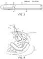
- FIG. 3is a schematic cross-sectional view of a sensor and delivery device employed in the invention.
- FIG. 4is a schematic diagram showing a further example system according to the present invention.
- FIG. 5is a schematic diagram showing example signal processing circuitry for use in the invention.
- FIG. 6is a schematic diagram of a yet further example of the invention in which wireless communication with the sensor is provided.
- FIG. 2is a schematic diagram of a system 10 in accordance with the present invention.
- the system 10 of the present inventioncomprises a delivery component, in this example a cannula 11 and delivery catheter 12 .
- a pressure sensor 13Positioned at a distal end of a delivery catheter 12 is a pressure sensor 13 .
- the sensor 13 and delivery device 12is a micro electro mechanical system (MEMS) integrated in a hollow flexible tube made out of biocompatible material.
- the sensor 13 and delivery devicehave a diameter of less than 1.0 mm, it is possible to insert the device using a simple minimally invasive technique.
- FIGS. 3 and 4show these components in more detail, they are formed from a flexible, hollow tube containing the pressure sensor element 13 connected electrically and mechanically to a flexible printed circuit board.
- the major part of the components, including the sensor 13is placed inside the subject, while the distal end is connected to an electronic front end (FE) module placed externally on the body including a signal processing component 14 (shown in FIG. 4
- the system 10 of the present inventionis operated as follows. Firstly, the cannula 11 is inserted through the abdominal wall 15 and in to the bladder 4 .
- the delivery catheter 12is then inserted in to the cannula and in to the bladder 4 so that the sensor 13 is positioned within the bladder 4 .
- the signal processing component 14is attached to the patient also so the patient is then mobile and can move about as normal. Pressure readings can then be taken from the sensor 13 and processed by the signal processing component 14 over a significant period of time, hours or possibly even days. Accordingly, pressure data can be obtained by the signal processing component 14 over a complete emptying and filling cycle of the bladder to provide far more data to a physician than is available with any prior art system.
- the cannula 11 of the system 10 of the present inventionis a relatively standard cannula.
- the sensor 13can be one of a number of sensors, but is, for example, a sensor of the type disclosed in “I. Clausen, et al., “A miniaturized pressure sensor with inherent biofouling protection designed for in vivo applications,” in 33rd Annual International Conference of the IEEE Engineering in Medicine and Biology Society, Boston, Mass. USA, 2011, pp. 1880-1883.”.
- the delivery catheter 12as it does not have to deliver any fluids in to the bladder, can be of a relatively narrow diameter, which simplifies insertion and reduces the size requirements of the cannula.
- the example shown in FIG. 2is inserted in to a bladder 4 .
- a similar approachcould be used to insert the sensor 13 in to another body cavity or tissue for pressure sensing another part of a patient's body. It could, for example, be inserted in to the cranial fluids to measure cranial fluid pressure using a similar delivery component 11 and delivery catheter 12 .
- the use of cannulais not relevant in this example. Instead, the sensor 13 is integrated in the tip of the catheter, which is inserted to drain away excessive brain fluid to e.g. the abdomen.
- the signal processing component 14may further comprise an additional pressure sensor and/or temperature sensor 16 so that data can be collected to compensate for variations in atmospheric pressure and temperature to improve the accuracy of the data from the pressure sensor 13 .
- FIG. 4shows a further example system 10 according to the present invention.
- This examplehas many components in common with the example of FIG. 2 , and where this is the case, components have been numbered identically.
- a second pressure sensor 16is provided with the system 10 , that pressure sensor 16 being arranged to be inserted subcutaneously in to the patient. It also connected to the processing component 14 .
- the second pressure sensor 16provides data on the pressure adjacent to the bladder 4 in the abdominal wall. This pressure data is fed to the signal processing component 14 for assessment in combination with the data received from the first pressure sensor 13 .
- Data from the second pressure sensor 16can be used to compensate for pressure generated by user movement and/or the atmosphere that might affect the bladder 4 but which is not directly related to pressure of fluid within the bladder. This enables the signal processing component 14 to compensate for such movements by providing data for analysis by a physician. It can also be used to compensate for atmospheric condition variations, for example.
- the signal of interestis the differential signal between the first 13 and the second sensor 16 . As the atmospheric condition and also change in body position affect both signals in the same way, so in most cases no other compensation is required.
- FIG. 5shows example system configurations with two sensors. The target signal from sensor 13 and the reference signal from the second sensor 16 are transmitted to two separate electronic modules 20 . 21 and from there further transmitted to an external data module (DAQ) 22 . Measurement data are either transferred from the DAQ module 22 via USB to a PC 23 or stored on a SD-memory card 24 .
- DAQexternal data module
- the signal processing component 14may be configured to issue an alarm if excessive pressure is detected either pressure sensor 13 , or if a pressure threshold is exceeded for a predetermined period of time. Such an alarm can be used to advise a physician of a serious medical condition, or can be used by a patient to remind them to empty their bladder, for example.
- the signal processing component 14may be configured to trigger a nerve stimulation component under certain pressure conditions, that nerve stimulation component then stimulating a patient's nervous system to encourage it to empty the patient's bladder, for example.
- FIG. 6shows an alternative system 10 of the present invention further comprising wireless communication means 17 for receiving data from the first 13 and/or second 16 pressure sensors. The received data is then transmitted, either by wired or wireless means to the signal processing component 14 .
- the sensor 13With such a system it is possible for the sensor 13 to be left in the bladder 4 or other body cavity and the delivery catheter 12 removed, together with removal of the cannula 11 . This yet further reduces patient discomfort whilst allowing the pressure sensor to remain within the body cavity to provide long term pressure readings.
- the first sensor 13 and/or the second sensormay have their own power supply and/or maybe configured to be charged capacitively or inductively by the wireless communication component.
- a number of different wireless communication techniquesare possible such as inductive methods, or other methods where the signal transmitter is “short-circuiting”/changing an EM-field set up by an external power source (and data receiver).
- the system of the inventionis to be comprehensive in all aspects, diagnostic, monitoring and therapeutic, and can be used throughout a process treatment of a patient.
- the first stage in the processis to explore whether there is a pressure related problem or not. If there is a suspected pressure related problem, long-term monitoring may be needed to clarify the extent and severity of the problem under physiological conditions in the second stage.
- the third stagewill involve therapeutic intervention with feedback systems to a device releasing medication, alarm system or electrical stimulation.
- the processwould have a schematic progression for all stages
- a first stageis diagnostic evaluation with sensors placed in fluid and/or tissue connected to external recording devices.
- Typical recording timewill be less than 60 minutes.
- a second stageis monitoring during physiological conditions with sensors placed in fluid and/or tissue connected to small external recording devices adapted for ambulatory use. Typical recording time will be 24-48 hours.
- a next stageis therapeutic intervention with sensors placed in fluid and/or tissue and implantable recording device connected to device. Expected duration of this stage will be from weeks up to several years.
- the system of the present inventionprovides significant benefits over the prior art systems in terms of ease of insertion in to a patient, as well as the ability to provide long term measurements, and allow independent movement for a patient with which the system is used. Furthermore, it also enables for provision of a system in which a patient can be assisted in control of their own bladder movement or control of their medical condition that can be monitored based on the fluid for which pressure is being detected. Furthermore, it also enables the possibility of a system in which auto stimulation of a body function or auto triggering of a medical device can be provided in a simple and effective manner based upon the monitored pressure.
Landscapes
- Health & Medical Sciences (AREA)
- Life Sciences & Earth Sciences (AREA)
- Engineering & Computer Science (AREA)
- Animal Behavior & Ethology (AREA)
- Veterinary Medicine (AREA)
- Public Health (AREA)
- Biomedical Technology (AREA)
- General Health & Medical Sciences (AREA)
- Surgery (AREA)
- Molecular Biology (AREA)
- Medical Informatics (AREA)
- Heart & Thoracic Surgery (AREA)
- Pathology (AREA)
- Biophysics (AREA)
- Physics & Mathematics (AREA)
- Physiology (AREA)
- Hematology (AREA)
- Signal Processing (AREA)
- Psychiatry (AREA)
- Artificial Intelligence (AREA)
- Computer Vision & Pattern Recognition (AREA)
- Urology & Nephrology (AREA)
- Cardiology (AREA)
- Neurosurgery (AREA)
- Computer Networks & Wireless Communication (AREA)
- Vascular Medicine (AREA)
- Gastroenterology & Hepatology (AREA)
- Nuclear Medicine, Radiotherapy & Molecular Imaging (AREA)
- Radiology & Medical Imaging (AREA)
- Measuring And Recording Apparatus For Diagnosis (AREA)
- Media Introduction/Drainage Providing Device (AREA)
- Measuring Pulse, Heart Rate, Blood Pressure Or Blood Flow (AREA)
- External Artificial Organs (AREA)
Abstract
Description
- a delivery component;
- an elongate sensor delivery member shaped so as to pass through the delivery component when it has been inserted in to a patient; and
- a first pressure sensor positioned at a distal end of the delivery member.
Claims (24)
Applications Claiming Priority (4)
| Application Number | Priority Date | Filing Date | Title |
|---|---|---|---|
| EP13190369 | 2013-10-25 | ||
| EP20130190369EP2865326A1 (en) | 2013-10-25 | 2013-10-25 | In-vivo pressure monitoring system |
| EP13190369.2 | 2013-10-25 | ||
| PCT/EP2014/072704WO2015059217A1 (en) | 2013-10-25 | 2014-10-23 | In-vivo pressure monitoring system |
Publications (2)
| Publication Number | Publication Date |
|---|---|
| US20160262642A1 US20160262642A1 (en) | 2016-09-15 |
| US11298038B2true US11298038B2 (en) | 2022-04-12 |
Family
ID=49517273
Family Applications (1)
| Application Number | Title | Priority Date | Filing Date |
|---|---|---|---|
| US15/030,105Active2035-03-04US11298038B2 (en) | 2013-10-25 | 2014-10-23 | In-vivo pressure monitoring system |
Country Status (11)
| Country | Link |
|---|---|
| US (1) | US11298038B2 (en) |
| EP (2) | EP2865326A1 (en) |
| JP (1) | JP6480440B2 (en) |
| KR (1) | KR102302422B1 (en) |
| CN (2) | CN113171072A (en) |
| CA (1) | CA2927869C (en) |
| DK (1) | DK3060108T3 (en) |
| ES (1) | ES2933561T3 (en) |
| FI (1) | FI3060108T3 (en) |
| PT (1) | PT3060108T (en) |
| WO (1) | WO2015059217A1 (en) |
Families Citing this family (7)
| Publication number | Priority date | Publication date | Assignee | Title |
|---|---|---|---|---|
| EP3424543B1 (en)* | 2016-03-02 | 2021-05-05 | Tsukada Medical Research Co., Ltd. | Bladder urodynamic measurement apparatus |
| EP3833256A4 (en)* | 2018-08-08 | 2022-04-06 | Incube Labs, Llc | Apparatus, systems and methods for sensing bladder fullness |
| US20200305742A1 (en) | 2019-03-27 | 2020-10-01 | Kamran Ghodsian | System and method for child-birth monitoring and assistance |
| CN112729670A (en)* | 2020-12-24 | 2021-04-30 | 联合汽车电子有限公司 | Pneumatic tool wear early warning system and early warning method thereof |
| JP2021072926A (en)* | 2021-01-26 | 2021-05-13 | 株式会社塚田メディカル・リサーチ | Unitary bladder urine dynamic state measuring apparatus |
| CN114451895A (en)* | 2022-02-07 | 2022-05-10 | 许开云 | An intelligent monitoring system for bladder safety pressure |
| CN116439668B (en)* | 2023-04-12 | 2024-09-24 | 成都维信电子科大新技术有限公司 | Positioning device of intra-abdominal pressure dynamic monitoring system |
Citations (14)
| Publication number | Priority date | Publication date | Assignee | Title |
|---|---|---|---|---|
| US5167237A (en)* | 1991-07-09 | 1992-12-01 | Long Island Jewish Medical Center | Apparatus for monitoring detrusor pressure exerted by a bladder |
| US5191898A (en) | 1990-10-22 | 1993-03-09 | Millar Instruments, Inc. | Method and assembly for measuring intracranial fluid characateristics |
| GB2308888A (en) | 1995-12-28 | 1997-07-09 | British Aerospace | Blood pressure measuring device |
| US5683422A (en)* | 1996-04-25 | 1997-11-04 | Medtronic, Inc. | Method and apparatus for treating neurodegenerative disorders by electrical brain stimulation |
| US6248080B1 (en)* | 1997-09-03 | 2001-06-19 | Medtronic, Inc. | Intracranial monitoring and therapy delivery control device, system and method |
| US6296615B1 (en)* | 1999-03-05 | 2001-10-02 | Data Sciences International, Inc. | Catheter with physiological sensor |
| US20020151816A1 (en)* | 2001-01-22 | 2002-10-17 | Rich Collin A. | Wireless MEMS capacitive sensor for physiologic parameter measurement |
| US20060247725A1 (en)* | 2005-04-28 | 2006-11-02 | Medtronic, Inc. | Multi-tube sensor for sensing urinary sphincter and urethral pressure |
| US7195594B2 (en)* | 2002-05-14 | 2007-03-27 | Pacesetter, Inc. | Method for minimally invasive calibration of implanted pressure transducers |
| US20080103408A1 (en)* | 2004-12-03 | 2008-05-01 | Wolfe Tory Medical, Inc. | Continuous Intra-Abdominal Pressure Monitoring Urinary Catheter With Optional Core Temperature Sensor |
| US20100057046A1 (en)* | 2008-09-03 | 2010-03-04 | Keimar, Inc | Systems for characterizing physiologic parameters and methods for use therewith |
| US20100152608A1 (en)* | 2008-09-12 | 2010-06-17 | Hatlestad John D | Chronically implanted abdominal pressure sensor for continuous ambulatory assessment of renal functions |
| US20100222637A1 (en) | 2009-02-27 | 2010-09-02 | Cvdevices, Llc | Systems and methods for selective auto-retroperfusion of the cerebral venous system |
| US9795336B2 (en)* | 2013-04-23 | 2017-10-24 | Gachon University Of Industry-Academic Cooperation Foundation | Device for measuring urinary detrusor pressure |
Family Cites Families (18)
| Publication number | Priority date | Publication date | Assignee | Title |
|---|---|---|---|---|
| DE9303812U1 (en)* | 1993-03-16 | 1993-12-09 | B. Braun Melsungen Ag, 34212 Melsungen | Cutlery for measuring bladder pressure (cystometry) |
| DE69928924T2 (en)* | 1998-05-21 | 2006-09-28 | The Government Of The United States Of America As Represented By The Secretary, Department Of Health And Human Services | CANNULA FOR THE SELECTIVE PRESSURE-DEPENDENT ADMINISTRATION OF THERAPEUTIC SUBSTANCES |
| US7198603B2 (en)* | 2003-04-14 | 2007-04-03 | Remon Medical Technologies, Inc. | Apparatus and methods using acoustic telemetry for intrabody communications |
| JP2007503286A (en)* | 2003-05-13 | 2007-02-22 | サバコア インコーポレイテッド | System and method for detecting, diagnosing and treating cardiovascular disease |
| US7252005B2 (en)* | 2003-08-22 | 2007-08-07 | Alfred E. Mann Foundation For Scientific Research | System and apparatus for sensing pressure in living organisms and inanimate objects |
| US7979137B2 (en)* | 2004-02-11 | 2011-07-12 | Ethicon, Inc. | System and method for nerve stimulation |
| AU2005212165A1 (en)* | 2004-02-11 | 2005-08-25 | Ethicon, Inc. | System and method for urodynamic evaluation utilizing micro-electronic mechanical system |
| SE531740C2 (en)* | 2005-11-21 | 2009-07-28 | Samba Sensors Ab | Device for measuring physical quantity in an anatomical organ |
| US20080071248A1 (en)* | 2006-09-15 | 2008-03-20 | Cardiac Pacemakers, Inc. | Delivery stystem for an implantable physiologic sensor |
| US8174395B2 (en)* | 2006-11-20 | 2012-05-08 | St. Jude Medical Systems Ab | Transceiver unit in a measurement system |
| JP2008206592A (en)* | 2007-02-23 | 2008-09-11 | Yoshihiko Hirao | Measuring system and program |
| JP2010530769A (en)* | 2007-06-14 | 2010-09-16 | カーディアック ペースメイカーズ, インコーポレイテッド | Body pressure measuring device and method |
| ES2474198T3 (en)* | 2007-09-25 | 2014-07-08 | Radi Medical Systems Ab | Pressure guide wire assembly |
| JP2011512997A (en)* | 2008-03-05 | 2011-04-28 | ホック,ロバート | Pressure sensing catheter |
| US8298227B2 (en)* | 2008-05-14 | 2012-10-30 | Endosense Sa | Temperature compensated strain sensing catheter |
| RU2478338C2 (en)* | 2008-09-11 | 2013-04-10 | Эсист Медикал Системз, Инк. | Device and method of physiological sensor delivery |
| US9901268B2 (en)* | 2011-04-13 | 2018-02-27 | Branchpoint Technologies, Inc. | Sensor, circuitry, and method for wireless intracranial pressure monitoring |
| EP2861145B1 (en)* | 2012-06-14 | 2019-07-24 | Autonomix Medical, Inc. | Devices and systems for diagnosis and treatment of overactive bladder |
- 2013
- 2013-10-25EPEP20130190369patent/EP2865326A1/ennot_activeWithdrawn
- 2014
- 2014-10-23WOPCT/EP2014/072704patent/WO2015059217A1/enactiveApplication Filing
- 2014-10-23ESES14787182Tpatent/ES2933561T3/enactiveActive
- 2014-10-23CNCN202110658768.8Apatent/CN113171072A/enactivePending
- 2014-10-23CACA2927869Apatent/CA2927869C/enactiveActive
- 2014-10-23JPJP2016526058Apatent/JP6480440B2/enactiveActive
- 2014-10-23CNCN201480058626.6Apatent/CN105682545A/enactivePending
- 2014-10-23PTPT147871826Tpatent/PT3060108T/enunknown
- 2014-10-23DKDK14787182.6Tpatent/DK3060108T3/enactive
- 2014-10-23FIFIEP14787182.6Tpatent/FI3060108T3/enactive
- 2014-10-23USUS15/030,105patent/US11298038B2/enactiveActive
- 2014-10-23EPEP14787182.6Apatent/EP3060108B1/enactiveActive
- 2014-10-23KRKR1020167013915Apatent/KR102302422B1/enactiveActive
Patent Citations (14)
| Publication number | Priority date | Publication date | Assignee | Title |
|---|---|---|---|---|
| US5191898A (en) | 1990-10-22 | 1993-03-09 | Millar Instruments, Inc. | Method and assembly for measuring intracranial fluid characateristics |
| US5167237A (en)* | 1991-07-09 | 1992-12-01 | Long Island Jewish Medical Center | Apparatus for monitoring detrusor pressure exerted by a bladder |
| GB2308888A (en) | 1995-12-28 | 1997-07-09 | British Aerospace | Blood pressure measuring device |
| US5683422A (en)* | 1996-04-25 | 1997-11-04 | Medtronic, Inc. | Method and apparatus for treating neurodegenerative disorders by electrical brain stimulation |
| US6248080B1 (en)* | 1997-09-03 | 2001-06-19 | Medtronic, Inc. | Intracranial monitoring and therapy delivery control device, system and method |
| US6296615B1 (en)* | 1999-03-05 | 2001-10-02 | Data Sciences International, Inc. | Catheter with physiological sensor |
| US20020151816A1 (en)* | 2001-01-22 | 2002-10-17 | Rich Collin A. | Wireless MEMS capacitive sensor for physiologic parameter measurement |
| US7195594B2 (en)* | 2002-05-14 | 2007-03-27 | Pacesetter, Inc. | Method for minimally invasive calibration of implanted pressure transducers |
| US20080103408A1 (en)* | 2004-12-03 | 2008-05-01 | Wolfe Tory Medical, Inc. | Continuous Intra-Abdominal Pressure Monitoring Urinary Catheter With Optional Core Temperature Sensor |
| US20060247725A1 (en)* | 2005-04-28 | 2006-11-02 | Medtronic, Inc. | Multi-tube sensor for sensing urinary sphincter and urethral pressure |
| US20100057046A1 (en)* | 2008-09-03 | 2010-03-04 | Keimar, Inc | Systems for characterizing physiologic parameters and methods for use therewith |
| US20100152608A1 (en)* | 2008-09-12 | 2010-06-17 | Hatlestad John D | Chronically implanted abdominal pressure sensor for continuous ambulatory assessment of renal functions |
| US20100222637A1 (en) | 2009-02-27 | 2010-09-02 | Cvdevices, Llc | Systems and methods for selective auto-retroperfusion of the cerebral venous system |
| US9795336B2 (en)* | 2013-04-23 | 2017-10-24 | Gachon University Of Industry-Academic Cooperation Foundation | Device for measuring urinary detrusor pressure |
Non-Patent Citations (1)
| Title |
|---|
| The above references were cited in an International Search Report, which is enclosed, that issued in the corresponding International Patent Application No. PCT/EP2014/072704. |
Also Published As
| Publication number | Publication date |
|---|---|
| CA2927869C (en) | 2023-08-01 |
| WO2015059217A1 (en) | 2015-04-30 |
| DK3060108T3 (en) | 2022-12-05 |
| ES2933561T3 (en) | 2023-02-10 |
| CN105682545A (en) | 2016-06-15 |
| FI3060108T3 (en) | 2023-01-13 |
| PT3060108T (en) | 2022-12-02 |
| CN113171072A (en) | 2021-07-27 |
| JP6480440B2 (en) | 2019-03-13 |
| CA2927869A1 (en) | 2015-04-30 |
| US20160262642A1 (en) | 2016-09-15 |
| EP2865326A1 (en) | 2015-04-29 |
| EP3060108A1 (en) | 2016-08-31 |
| JP2016533802A (en) | 2016-11-04 |
| KR102302422B1 (en) | 2021-09-15 |
| KR20160075732A (en) | 2016-06-29 |
| EP3060108B1 (en) | 2022-11-23 |
Similar Documents
| Publication | Publication Date | Title |
|---|---|---|
| US11298038B2 (en) | In-vivo pressure monitoring system | |
| JP2972251B2 (en) | Long-term measurement system for internal pressure | |
| US8942818B2 (en) | Communication with an implantable medical device during implantation | |
| US9826936B2 (en) | Body cavity physiological measurement device | |
| CN111132707A (en) | Instrumented drive train using flexible artificial skin sensing array | |
| US20120010525A1 (en) | Compartment Syndrome Monitoring Systems and Methods | |
| EP3209200B1 (en) | Apparatus for testing distal colonic and anorectal function | |
| US20090024054A1 (en) | Implantable medical device | |
| US20060025704A1 (en) | Device for measuring parameters in the brain | |
| CN110013241A (en) | Intracranial pressure multi-probe monitoring system | |
| Wright et al. | From wires to waves, a novel sensor system for in vivo pressure monitoring | |
| Lee | Miniaturized human insertable cardiac monitoring system with wireless power transmission technique | |
| US7753903B1 (en) | Method and implantable apparatus for the intra-osseal monitoring of biological substances in the bone marrow, including without limitation, glucose, the intra-osseal delivery of drugs, including without limitation, insulin, the integration of foregoing, and related or ancillary matters | |
| Jetzki et al. | A multisensor implant for continuous monitoring of intracranial pressure dynamics | |
| Weydts et al. | A novel method to investigate bladder wall behavior by acceleration and pressure sensing | |
| AU2018389184A1 (en) | A system for adjusting the shape of a breast implant | |
| US20250032004A1 (en) | Externally directed calibration for implantable medical device | |
| Tan et al. | Development of a minimally invasive implantable wireless vital signs sensor platform | |
| NZ538492A (en) | Device for measuring parameters in the brain |
Legal Events
| Date | Code | Title | Description |
|---|---|---|---|
| AS | Assignment | Owner name:SINTEF TTO AS., NORWAY Free format text:ASSIGNMENT OF ASSIGNORS INTEREST;ASSIGNORS:GLOTT, THOMAS;CLAUSEN, INGELIN;REEL/FRAME:038986/0825 Effective date:20160610 | |
| STPP | Information on status: patent application and granting procedure in general | Free format text:ADVISORY ACTION MAILED | |
| STPP | Information on status: patent application and granting procedure in general | Free format text:DOCKETED NEW CASE - READY FOR EXAMINATION | |
| STPP | Information on status: patent application and granting procedure in general | Free format text:NON FINAL ACTION MAILED | |
| STPP | Information on status: patent application and granting procedure in general | Free format text:RESPONSE TO NON-FINAL OFFICE ACTION ENTERED AND FORWARDED TO EXAMINER | |
| STPP | Information on status: patent application and granting procedure in general | Free format text:FINAL REJECTION MAILED | |
| STPP | Information on status: patent application and granting procedure in general | Free format text:DOCKETED NEW CASE - READY FOR EXAMINATION | |
| STPP | Information on status: patent application and granting procedure in general | Free format text:NON FINAL ACTION MAILED | |
| STPP | Information on status: patent application and granting procedure in general | Free format text:RESPONSE TO NON-FINAL OFFICE ACTION ENTERED AND FORWARDED TO EXAMINER | |
| STPP | Information on status: patent application and granting procedure in general | Free format text:NOTICE OF ALLOWANCE MAILED -- APPLICATION RECEIVED IN OFFICE OF PUBLICATIONS | |
| STPP | Information on status: patent application and granting procedure in general | Free format text:PUBLICATIONS -- ISSUE FEE PAYMENT VERIFIED | |
| STCF | Information on status: patent grant | Free format text:PATENTED CASE | |
| MAFP | Maintenance fee payment | Free format text:PAYMENT OF MAINTENANCE FEE, 4TH YEAR, LARGE ENTITY (ORIGINAL EVENT CODE: M1551); ENTITY STATUS OF PATENT OWNER: LARGE ENTITY Year of fee payment:4 |