US11297709B2 - Circuit arrangement for enabling motion detection to control an outdoor light - Google Patents
Circuit arrangement for enabling motion detection to control an outdoor lightDownload PDFInfo
- Publication number
- US11297709B2 US11297709B2US14/519,267US201414519267AUS11297709B2US 11297709 B2US11297709 B2US 11297709B2US 201414519267 AUS201414519267 AUS 201414519267AUS 11297709 B2US11297709 B2US 11297709B2
- Authority
- US
- United States
- Prior art keywords
- light
- characterization data
- circuit arrangement
- switch
- timing characterization
- Prior art date
- Legal status (The legal status is an assumption and is not a legal conclusion. Google has not performed a legal analysis and makes no representation as to the accuracy of the status listed.)
- Active, expires
Links
Images


Classifications
- H—ELECTRICITY
- H05—ELECTRIC TECHNIQUES NOT OTHERWISE PROVIDED FOR
- H05B—ELECTRIC HEATING; ELECTRIC LIGHT SOURCES NOT OTHERWISE PROVIDED FOR; CIRCUIT ARRANGEMENTS FOR ELECTRIC LIGHT SOURCES, IN GENERAL
- H05B47/00—Circuit arrangements for operating light sources in general, i.e. where the type of light source is not relevant
- H05B47/10—Controlling the light source
- H05B47/16—Controlling the light source by timing means
- H—ELECTRICITY
- H05—ELECTRIC TECHNIQUES NOT OTHERWISE PROVIDED FOR
- H05B—ELECTRIC HEATING; ELECTRIC LIGHT SOURCES NOT OTHERWISE PROVIDED FOR; CIRCUIT ARRANGEMENTS FOR ELECTRIC LIGHT SOURCES, IN GENERAL
- H05B47/00—Circuit arrangements for operating light sources in general, i.e. where the type of light source is not relevant
- H05B47/10—Controlling the light source
- H05B47/175—Controlling the light source by remote control
- H05B47/185—Controlling the light source by remote control via power line carrier transmission
- H—ELECTRICITY
- H05—ELECTRIC TECHNIQUES NOT OTHERWISE PROVIDED FOR
- H05B—ELECTRIC HEATING; ELECTRIC LIGHT SOURCES NOT OTHERWISE PROVIDED FOR; CIRCUIT ARRANGEMENTS FOR ELECTRIC LIGHT SOURCES, IN GENERAL
- H05B47/00—Circuit arrangements for operating light sources in general, i.e. where the type of light source is not relevant
- H05B47/10—Controlling the light source
- H05B47/175—Controlling the light source by remote control
- H05B47/196—Controlling the light source by remote control characterised by user interface arrangements
- H—ELECTRICITY
- H05—ELECTRIC TECHNIQUES NOT OTHERWISE PROVIDED FOR
- H05B—ELECTRIC HEATING; ELECTRIC LIGHT SOURCES NOT OTHERWISE PROVIDED FOR; CIRCUIT ARRANGEMENTS FOR ELECTRIC LIGHT SOURCES, IN GENERAL
- H05B47/00—Circuit arrangements for operating light sources in general, i.e. where the type of light source is not relevant
- H05B47/10—Controlling the light source
- H05B47/105—Controlling the light source in response to determined parameters
- H05B47/11—Controlling the light source in response to determined parameters by determining the brightness or colour temperature of ambient light
- H—ELECTRICITY
- H05—ELECTRIC TECHNIQUES NOT OTHERWISE PROVIDED FOR
- H05B—ELECTRIC HEATING; ELECTRIC LIGHT SOURCES NOT OTHERWISE PROVIDED FOR; CIRCUIT ARRANGEMENTS FOR ELECTRIC LIGHT SOURCES, IN GENERAL
- H05B47/00—Circuit arrangements for operating light sources in general, i.e. where the type of light source is not relevant
- H05B47/10—Controlling the light source
- H05B47/105—Controlling the light source in response to determined parameters
- H05B47/115—Controlling the light source in response to determined parameters by determining the presence or movement of objects or living beings
- Y—GENERAL TAGGING OF NEW TECHNOLOGICAL DEVELOPMENTS; GENERAL TAGGING OF CROSS-SECTIONAL TECHNOLOGIES SPANNING OVER SEVERAL SECTIONS OF THE IPC; TECHNICAL SUBJECTS COVERED BY FORMER USPC CROSS-REFERENCE ART COLLECTIONS [XRACs] AND DIGESTS
- Y02—TECHNOLOGIES OR APPLICATIONS FOR MITIGATION OR ADAPTATION AGAINST CLIMATE CHANGE
- Y02B—CLIMATE CHANGE MITIGATION TECHNOLOGIES RELATED TO BUILDINGS, e.g. HOUSING, HOUSE APPLIANCES OR RELATED END-USER APPLICATIONS
- Y02B20/00—Energy efficient lighting technologies, e.g. halogen lamps or gas discharge lamps
- Y02B20/40—Control techniques providing energy savings, e.g. smart controller or presence detection
- Y02B20/44—
- Y—GENERAL TAGGING OF NEW TECHNOLOGICAL DEVELOPMENTS; GENERAL TAGGING OF CROSS-SECTIONAL TECHNOLOGIES SPANNING OVER SEVERAL SECTIONS OF THE IPC; TECHNICAL SUBJECTS COVERED BY FORMER USPC CROSS-REFERENCE ART COLLECTIONS [XRACs] AND DIGESTS
- Y02—TECHNOLOGIES OR APPLICATIONS FOR MITIGATION OR ADAPTATION AGAINST CLIMATE CHANGE
- Y02B—CLIMATE CHANGE MITIGATION TECHNOLOGIES RELATED TO BUILDINGS, e.g. HOUSING, HOUSE APPLIANCES OR RELATED END-USER APPLICATIONS
- Y02B20/00—Energy efficient lighting technologies, e.g. halogen lamps or gas discharge lamps
- Y02B20/72—Energy efficient lighting technologies, e.g. halogen lamps or gas discharge lamps in street lighting
Definitions
- the present inventionrelates generally to outdoor lights, and in particular, to a circuit arrangement enabling motion detection to control an outdoor light.
- Some conventional outdoor lightshave sensors to implement motion detection or dusk-to-dawn lighting operation, for example.
- outdoor lightseither provide limited functionality, or are difficult to operate as desired.
- the controls of conventional outdoor lightsare located with the outdoor light itself, adjusting a feature or function of the light can be difficult.
- a motion detector associated with an outdoor lightmay have to be set to detect motion in certain locations. Because outdoor lights are often used as security lights, it is important that the lights operate as intended in order to provide the desired security feature.
- dusk-to-dawn featuresBecause a light having a dusk-to-dawn feature must switch at some level of light which is greater than complete darkness in order to compensate for natural lighting occurrences such as moonlight, outdoor lights implementing dusk-to-dawn features must inherently be turned on when it is light out. Further, because an outdoor light implementing a dusk-to-dawn feature may operate for an extended period of time, it may be beneficial to limit the amount of time that the light is on. That is, conventional outdoor lights having dusk-to-dawn features may operate during a fixed time period based upon the sensitivity of a sensor. As a result, the outdoor light may operate during times which may not be beneficial.
- a circuit arrangement for controlling an on/off state of an outdoor lightcomprising an indoor light switch coupled to control the on/off stage of the outdoor light; a motion detector associated with the outdoor light, wherein the motion detector is remote from the indoor light switch; and a mode actuator implemented on a user interface of the indoor light switch, wherein the mode actuator is movable to a position enabling the use of the motion detector.
- the circuit arrangementmay further comprise a control actuator enabling an adjustment of a setting of the motion detector from a user interface of the indoor light switch, wherein the setting of the control actuator will affect the on/off state of the outdoor light when the mode actuator is in the position enabling the use of the motion detector.
- the control actuatormay enable setting an amount of time that an outdoor light is on in response to a signal from the motion detector.
- a user interface of the indoor light switchenables manually controlling the on/off state of the light.
- a circuit arrangement for controlling an on/off state of the outdoor lightcomprises an indoor light switch coupled to control the on/off stage of the outdoor light; a motion detector associated with the outdoor light, wherein the motion detector is remote from the indoor light switch; a mode actuator implemented on a user interface of the indoor light switch, wherein the mode actuator is movable to a timer position; and a memory storing timing characterization data, wherein the control circuit controls the on/off state of the outdoor light in response to timing characterization data stored in the memory.
- the other circuit arrangementmay further comprise a control actuator enabling an adjustment of a setting of the motion detector from the user interface of the indoor light switch, wherein the setting of the control actuator will affect the on/off state of the outdoor light.
- the circuit arrangementmay comprise a user interface of the indoor light switch enables manually controlling the on/off state of the light, wherein the user interface enables overriding the motion detector or a timer function in response to the manually controlling of the on/off state of the light.
- a circuit arrangement for controlling an on/off state of the outdoor lightcomprises an indoor light switch coupled to control the on/off state of the outdoor light; a motion detector associated with the outdoor light, wherein the motion detector is remote from the indoor light switch; and a control circuit coupled to the mode actuator, wherein the control circuit controls the on/off state of the outdoor light in response to a motion detector.
- control actuatormay enable setting an amount of time that an outdoor light is on in response to a signal from the motion detector.
- user interface of the indoor light switchmay enable manually controlling the on/off state of the light, including overriding the motion detector or a timing function in response to the manually controlling of the on/off state of the light.
- FIG. 1shows an arrangement of an outdoor light and corresponding indoor user interface according to an embodiment of the present invention
- FIG. 2is a perspective view of a front panel of an indoor portion of a light arrangement comprising a user interface adapted to control a motion detection feature of an outdoor light according to a embodiment of the present invention
- FIG. 3is a perspective view of a front panel of an indoor portion of a light arrangement comprising a user interface having control actuators adapted to control a motion detection feature of an outdoor light according to a embodiment of the present invention
- FIG. 4is a perspective view of a front panel of an indoor portion of a light arrangement comprising a user interface adapted to programmably control a motion detection feature of an outdoor light according to a embodiment of the present invention
- FIG. 5is a perspective view of a front panel of an indoor portion of a light arrangement comprising a user interface having control actuators control to control a motion detection feature of and adapted to programmably control an outdoor light according to a embodiment of the present invention
- FIG. 6is a perspective view of a front panel of an indoor portion of a light arrangement comprising a user interface adapted to control an ambient light feature of an outdoor light according to a embodiment of the present invention
- FIG. 7is a perspective view of a front panel of an indoor portion of a light arrangement comprising a user interface having control actuators adapted to control an ambient light feature of an outdoor light according to a embodiment of the present invention
- FIG. 8is a perspective view of a front panel of an indoor portion of a light arrangement comprising a user interface adapted to programmably control an ambient light feature of an outdoor light according to a embodiment of the present invention
- FIG. 9is a perspective view of a front panel of an indoor portion of a light arrangement comprising a user interface having control actuators to control an ambient light feature of and adapted to programmably control an outdoor light according to a embodiment of the present invention
- FIG. 10is a block diagram of a light arrangement having an outdoor light and corresponding sensor and control circuit and having a user interface accessible by a user from inside a building implementing the light arrangement according to an embodiment of the present invention
- FIG. 11is a block diagram of a control circuit and mode and control actuators according to an embodiment of the present invention.
- FIG. 12is a block diagram of a control circuit associated with an outdoor light of a light arrangement according to an embodiment of the present invention.
- FIG. 13is a block diagram of a control circuit and mode and control actuators according to an alternate embodiment of the present invention.
- FIG. 14is a block diagram of a control circuit associated with an outdoor light of a light arrangement according to an alternate embodiment of the present invention.
- FIG. 15is a block diagram of a control circuit enabling the programmable implementation of a light having an outdoor sensor according to an embodiment of the present invention
- FIG. 16is a diagram showing the transmission of control signals as a modulated AC signal according to an embodiment of the present invention.
- FIG. 17is a data stream comprising DC signals sent on AC power lines for providing power to an outdoor light according to an embodiment of the present invention
- FIG. 18is a data frame for transmitting mode information according to an embodiment of the present invention.
- FIG. 19is a data frame for transmitting mode and control information associated with an outdoor light having a motion detector according to an embodiment of the present invention.
- FIG. 20is a data frame for transmitting mode, control and address information associated with an outdoor light having a motion detector according to an embodiment of the present invention
- FIG. 21is a data frame for transmitting mode and control information associated with an outdoor light having an ambient light detector according to an embodiment of the present invention
- FIG. 22is a data frame for transmitting a sensor status signal associated with an outdoor light having a sensor according to an embodiment of the present invention
- FIG. 23is a program screen enabling the entry of timing characterization data including motion detection settings by a computer for implementing a light having a motion detector according to an embodiment of the present invention
- FIG. 24is a program screen enabling the entry of timing characterization data including ambient light detection settings by a computer for implementing a light having an ambient light feature according to an embodiment of the present invention
- FIG. 25is a program screen enabling the entry of advanced settings of timing characterization data by a computer for implementing a light timer according to an embodiment of the present invention
- FIG. 26is a program screen enabling the entry of timing characterization data for a plurality of on/off periods for implementing a light timer according to an embodiment of the present invention
- FIG. 27is a program screen enabling the entry of timing characterization data for a single on/off period for implementing a light timer according to an embodiment of the present invention
- FIG. 28is a program screen enabling the entry of timing characterization data by a computer for a daylight savings feature when implementing a light timer according to an embodiment of the present invention
- FIGS. 29A and 29Bare program screens enabling the entry of multiple sets of timing characterization data when implementing a light timer according to an embodiment of the present invention
- FIG. 30is a flow chart showing a method of operating an outdoor light having a motion detector according to an embodiment of the present invention.
- FIG. 31is a flow chart showing a method of operating a light having an ambient light detector according to an embodiment of the present invention.
- FIG. 32is a flow chart showing a method of communicating control signals to a control circuit associated with an outdoor light according to an embodiment of the present invention
- FIG. 33is a flow chart showing a method of communicating control signals between a control circuit associated with an outdoor light and a control circuit at an indoor user interface according to an embodiment of the present invention
- FIG. 34is a flow chart showing a method of implementing an outdoor light having an ambient light detector according to an embodiment of the invention.
- FIG. 35is a flow chart showing a method of enabling turning off an outdoor light having an ambient light detector before dawn according to an alternate embodiment of the invention
- FIG. 36is a flow chart showing a method of generating timing characterization data according to an embodiment of the present invention.
- FIG. 37is a flow chart showing a method of loading timing characterization data according to an embodiment of the present invention.
- FIG. 38is a flow chart showing a method of accessing timing characterization data from a plurality of sources according to an embodiment of the present invention.
- FIG. 39is a flow chart showing a method of configuring multiple switches according to an embodiment of the present invention.
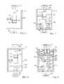
- FIG. 1a block diagram of an arrangement of an outdoor light and corresponding indoor user interface according to an embodiment of the present invention is shown.
- a building 102receiving a source of power from a power line 104 coupled to an electric box 106 for supplying power to the building 102 .
- the building 102may comprise various lighting elements at various locations, both internal and external. While the circuits, user interfaces and methods set forth below find particular application with outdoor lights, they may also be used with indoor lights where a sensor or a user interface for controlling a sensor may not be easily accessible.
- the lights of the building of FIG. 2are powered by electrical wiring 108 represented in FIG. 1 by the framing of the building as shown.
- a switch 110 on an inside of a wall 111is coupled, by way of wiring elements 112 in the wall, to an outdoor light 114 which may be attached to the wall 111 as an outdoor light fixture.
- the switch 110may be implemented as in a wall switch and located in a conventional junction box associated with the electrical wiring 108 .
- the switch 110comprises a user interface which enables control of the operation of the outdoor light 114 .
- the user interface associated with the switch 110enables a user of the outdoor light to control the operation of the sensor 115 which will control the on/off state of the light bulb 116 . While the particular arrangement of lights and switches are shown in conjunction with the building 102 by way of example in FIG. 1 for purposes of explanation, it should be understood that other arrangements of and additional lights and user interfaces as described below could be employed.
- the methods, circuits and user interfaces of the present inventionprovide significant benefits in terms of improved functionality of an outdoor light and reduced energy consumption.
- a unique circuit arrangementenables changing modes of operation of an outdoor light which is normally set to turn on and off in response to an external stimulus (e.g. motion or an ambient light level). While some conventional outdoor lights are set to turn on based upon external stimulus, the circuits and methods set forth below enable setting modes from a user interface inside, and in some situations, overriding functions normally responsive to an external sensor. That is, while a conventional on/off switch may apply power to an outdoor light, or conventional motion or ambient light sensors may change the state of the outdoor light, the methods, circuits and user interfaces enable improved flexibility, reduced power consumption and reduced waste.
- Conventional wiringonly allows power to be applied to an outdoor light. While timers located at the light switch inside of a building may be used to control power to the outdoor light, a motion detector or an ambient light sensor is located with the outdoor light in order respond to a particular condition (i.e. motion or light) at the outdoor light. Accordingly, conventional outdoor lights also have controls for the motion detector located outdoor with the light itself. Such an arrangement is inconvenient because it requires a user has to go outside to make a change. In cases where an outdoor light is difficult to access (e.g. requiring a ladder), the change is even more inconvenient. In any case, an outdoor light having sensor functionality which is used for security purpose may also susceptible to tampering if the sensor or other controls are located outside with the outdoor light.
- the circuit arrangement of the present inventionnot only makes it easier for a user to change a setting of an outdoor light having sensing capability, but safer by preventing a user from having to go outside to manually turn on a light. Accordingly, the various embodiments set forth below enable a user to not only override the sensor from inside, but also to set the settings of the sensor from inside. For example, a user may want to turn on a light which is normally operated by a motion detector to determine whether an unauthorized person is outside. That user would be reluctant to go outside to turn on the light (e.g. engaging the motion detector of the light) to determine whether an unauthorized person is in the area. Such a case may exist when an unauthorized person has blocked the motion detector so that the motion of an unauthorized person won't be detected. As will be apparent in the following specific embodiments, the improved control and operation of outdoor lights having sensors not only reduces energy consumption, but improves security.
- FIG. 2a perspective view of a front panel of an indoor portion of a light arrangement comprising a user interface adapted to control a motion detector feature of an outdoor light according to a embodiment of the present invention is shown.
- the switch 110comprises a user interface 201 having a mode actuator 204 .
- the mode actuator 204is movable between an off position (for blocking power to the outdoor light), a sensor position (such as a motion position for enable the outdoor light to operate in response to the sensor 115 comprising a motion detector), and an on position. In the on position, the mode actuator 204 enables overriding the motion detector to turn the light on.
- one or more control circuits associated with the lightto enable the light to be turned on in response to user input rather than only turned on in response to the motion detector.
- a usermay desire to override the motion detector and turn the light on. For example, if a user is concerned that an intruder is in the area covered by the motion detector, but is waiting for the light to go off and to avoid the motion detector, the user can simply turn the light on. Further, there may be situations, such as during a party in the evening, when the user may desire to use the outdoor light for general purpose lighting. That is, rather than having to change the setting on the light, the user may simply turn the light on from the user interface.
- a feedback portioncomprising a status indicator light 206 according to the embodiment of FIG. 2 , enables a user to determine a status of the outdoor light.
- the status indicator lightcould be a multicolor light emitting diode (LED), for example.
- LEDmulticolor light emitting diode
- the on/off state of the lightwill be controlled in response to a signal generated at the user interface to enable the light to be turned on regardless of the status of the motion detector.
- a first control actuator 304comprises an actuator for setting a detection angle of the motion detector.
- the first control actuator 304is movable between four settings, shown in FIG. 3 as 45 degrees, 90 degrees, 135 degrees, and 180 degrees, where the settings represent the range extending out from the sensor through which a moving object will be detected.
- the lightmay function best with a certain angle setting for the motion detector. For example, if the angle of detection is too wide, the motion detector may unnecessarily detect the motion of a neighbor's dog in an adjacent yard.
- a control actuator for controlling an angle of operation of a motion detector or some other feature of the outdoor lightis located with the light itself, a user would not only have to go outside to adjust the setting of the control actuator, but may need to get on a ladder to adjust the setting of the control actuator. Given the nature of the angle of detection of a motion detector, it may not be possible to immediately determine whether the adjustment of the angle of detection results in a correct angle of detection. In such a case, the user may have to again adjust the setting of the control actuator and proceed with another trial period of the outdoor light.
- control actuator settingsmay be adequate after initial settings are found, a user may be required to change control actuator settings periodically.
- environmental elements which may affect a motion detectormay vary based upon seasons, such as a tree branch only with leaves which would activate the motion detector, or may first occur at a later period of time, such as when a new tree which is planted. Accordingly, the ability to change a setting of a control actuator from a user interface which is easily accessible is desirable for a user.
- the user interface 301 of FIG. 3further comprises an on-time control actuator 306 which enables the user to establish how long the light will remain on after the motion detector is activated (when the mode actuator 204 is in the motion position). In some circumstances, wildlife may be detected by the motion detector, leading to the light be activated somewhat frequently. In such a case, the user may desire that the on-time is set for a short period of time. In contrast, if the light is used in a fenced in yard and the motion detector would only be actuated when an intruder were in the back yard, the user of the light may desire to set the on-time actuator to the maximum on time.
- the first control actuator 304adjusts the sensitivity of the sensor 115
- the second control actuator 306controls an on time of the outdoor light. Accordingly, the embodiments of FIGS. 1 and 2 provide a simple user interface which significantly improves the functionality of outdoor lights having a motion detection features, and enables a user to control the functionality of the of the motion detector from a user interface which is located remote from the light, such as indoors.
- the mode actuator and the control actuatorsmay be implemented in a user interface 401 enabling timer functions, wherein timer characterization data having sensor settings are downloaded to the switch 110 .
- the user interface 401comprises a mode actuator 402 which not only enables the off, motion and on modes as set forth above in the description of FIGS. 2-3 , but also enable a timer mode. More particularly, when the mode actuator 402 is in a timer position, the outdoor light will be implemented according to timing characteristics which are programmed into the switch 110 or other portion of the outdoor light, such as a control circuit for the outdoor light itself.
- the user interface 401comprises a slot 404 for receiving a memory element for having timing characterization data for operating the outdoor light.
- the switch 110may operate based upon the timing characterization data stored on the memory element inserted into the slot 404 , or based upon data transferred from the memory element inserted into the slot to another memory of the switch in response to the actuation of the configuration actuator 406 . That is, the configuration actuator 406 enables transferring timing characterization data from the memory element to a memory of the switch 110 by pressing the configuration actuator 406 while the memory element is in the slot 404 , for example.
- the status indicator 206provides additional functionality for a switch 110 having timer capability. For example, a red light provided by the status indicator 206 could indicate that the switch does not have data or that it is not operating properly when in the timer mode, an orange light provided by the status indicator could indicate that the switch is receiving timing characterization data from a portable memory device inserted in slot 404 , and a green light could indicate that timing characterization data has been successfully downloaded and the portable memory device may be removed.
- the status indicator 206may flash red when the light is not functioning properly in the timer mode, allowing the status light to show red when the light attached to the switch are turned off, and green when the light is turned on.
- the actuatorwould enable the status indicator to not only provide immediate feedback to a user (i.e. enable the user to see the status of the light attached to the switch without going to the light to see the status in the case of an outdoor light), but also enable a user to see if the switch is not providing the correct or desired settings for the light in the timer mode. For example, a user may notice that the status indicator is red at a time when the user believes that the light should be on or when a user would like the light to be on. The user can then reload the timing characterization data to ensure that the data is correct and includes the data that the user desires. Such user feedback can lead to a significant reduction in energy in cases where lights are on longer than necessary.
- the mode actuator 402may also be implemented to enable a user to manually override the timing characterization data and turn on or off a light attached to the switch while maintaining the switch in the timer position. Such a feature will prevent a user from inadvertently forgetting to return the switch to the timer position.
- the switchWhen the mode actuator 402 is in the timer position, the switch would operate according to timing configuration data stored on or downloaded from a portable memory device and received by way of control actuators on the timer.
- the mode actuator 402When the mode actuator 402 is moved to the “off” position, the switch 110 will cause the light to remain off. Conversely, when the mode actuator 402 is moved to the “on” position, the switch will cause a light to remain on.
- the mode actuator 402preferably may be pressed inward when in the timer position to override the current setting until the next switching of the light. For example, if a light is set in the on state, the light will be turned off when the mode actuator 402 is pressed and will remain off until the timer is set to turn the light on again. Alternatively, if a light is currently set in the off state, the light will be turned on when the mode actuator 402 is pressed and will remain on until the timer is set to turn the light off again. While the mode actuator 402 provides on example of an actuator for manually controlling a light attached to the timer, it should be understood that other actuators could be employed according to the invention. On benefit of the embodiment of FIG. 4 is that it provides timer capability without the expense of a display and other actuators required to implement the timer. Such a switch having timing capabilities without a display can significantly reduce the cost of the timer.
- a display 502provides additional feedback and data, and enables a user to see one or more current settings of timer function and to determine whether the switch is operating properly. More particularly, the display 502 comprises a clock portion 504 which may be set to display “12-hour time” where a separate AM-PM portion 506 would indicate whether the current time was AM or PM (shown here as PM). The display would also preferably include a day-of-the-week portion 508 , where the current day of the week is shown here to be Tuesday. The embodiment of FIG. 5 also preferably includes an on/off indicator 510 which will show either “on” or “off” highlighted to indicate a current setting of the timer.
- a review actuator 512may be implemented to enable an evaluation of the timing characterization data.
- the review actuatormay then be pressed, for example, to determine the timing characteristics of the switch. That is, when the review actuator is pressed, the entire timing characterization will be shown on the display. For example, the day starting with Sunday would be indicated on the display with the on and off times being indicated in sequence with a corresponding time for each on and off setting by the on/off indicator 510 . According to alternate embodiments, depressing the review actuator will cause the timing characterization of the current day to be displayed, where depressing of the review actuator again would cause the timing characterization data for the following day to be displayed.
- depressing and holding the review actuator for a predetermined period of timewould cause the entire timing characterization data from Sunday to Saturday to be displayed.
- an angle setting or on time valuemay be loaded into the switch with the timing characterization data as will be described in more detail below
- the embodiment of FIG. 5may instead include the control actuators 304 and 306 to set the angle setting and on time value. While various features are shown in different embodiments, the different features may be interchanged in the different embodiments as desired.
- FIGS. 6-9various embodiments of a switch 110 including an ambient light sensor mode are shown.
- a usermay want to turn on a light before the ambient light sensor detects that it is dark enough to turn on the light or after the ambient light sensor detects a low light condition associated with dusk.
- a light sensormay detect dusk at an appropriate time to turn on an outdoor light for a user, there may be occasions when a user may want to turn on the outdoor light before the light sensor would otherwise turn on the light.
- a usermay be entertaining outside, and would like to turn one or more outdoor lights before the light sensor would normally turn on the light.
- the switch 110comprises a user interface 601 having a mode actuator 602 .
- the mode actuator 602is movable between an off position (for blocking power to the outdoor light), a sensor position (i.e. a low ambient light position for enabling the outdoor light to operate in response to the sensor 115 comprising an ambient light detector), and an on position. In the on position, the mode actuator 402 enables overriding an ambient light detector to turn the light on.
- one or more control circuits associated with the outdoor light arrangementenables the light to be turned on rather than only turned on in response to the ambient light detector.
- the lightwill be controlled in response to a signal generated at the user interface to enable the light to be turned on regardless of the status of the ambient light detector.
- the circuits and methods of the present inventionenable the operation of the light to not turn on until after a predetermined amount of time after a low ambient light condition is detected, to operate for a predetermined number of hours (e.g. 2, 4, 6 or 8 hours after initially detecting a low ambient light condition), or to turn off a predetermined amount of time before the detection of a low ambient light condition associated with dawn.
- the controlsenable adjusting settings for the ambient light sensor from inside at a user interface associated with the switch 110 .
- a user interface having control actuators adapted to control a light sensor feature of an outdoor lightis shown in FIG. 7 .
- a first control actuator 704 and a second control actuator 706are provided.
- the first control actuator 704comprises an actuator for setting a delay period for turning the light on. That is, the first control actuator 704 sets an on time for the light after the ambient light detector detects a low enough level of light to be considered dusk.
- the first control actuator 704is movable between five settings, shown in FIG.
- FIGS. 6-9also adjust the sensitivity of the sensor and the on time of the light, where the first control actuator 704 indirectly adjusts the sensitivity of the sensor 115 , while the second control actuator 706 controls an on time of the outdoor light.
- a light using an ambient light detectormay turn on earlier than desired at an ambient light detector trigger level.
- a light responsive to an ambient light detectormay turn on when the sun is just beginning to set (i.e. at an ambient light level which is greater than a moonlit night during a full moon for example).
- the lightmay be turning on too early.
- the use of such an ambient light detectormay detract from the overall appearance of the lighting when the lights are turned on early. Further, operating the outdoor lights for a greater period of time than is necessary results in wasted energy. Accordingly, controlling the on time of the light after the detection of a low level of light is beneficial to the user.
- an ambient light level representing dawnmay be beneficial to turn off the light before an ambient light level representing dawn is detected.
- aesthetic lightinga user may only desire that the outdoor lighting be on for a certain period of time during the evening (e.g. a certain number of hours), but may not wish to be constantly adjusting the on time for the light based upon specific timer settings which would have to be adjusted with the change of seasons.
- security lightingthe user may desire that the lights are on for a greater period of time, but may not be particularly concerned about keeping the lights on as dusk approaches.
- turning a light on using an ambient light detectorturning the light off would require that the ambient light level to rise to a certain level, such as the ambient light detector trigger level, after the sun starts to rise.
- a control actuator 706enables turning off the light at some selected time other than when a minimum amount of light is detected by the ambient light sensor to turn the light off.
- the control actuator 706enables selecting an off-time setting.
- the off-time settingmay be a period of time that the light is on, or an early off period representing the amount of time before the ambient light detector trigger level is estimated to the detected.
- the control actuator 706is movable to either a fixed number of hours that the light is on after it has been turned on.
- the settings on the left side of the dashed line through the control actuator 706represent the number of hours (e.g. 2, 4 or 6 hours as well as a dawn setting) that the light is on (i.e. an on-time setting) after it is turned on.
- the settings on the right side of the dashed line through the control actuator 706represents an early off-time setting with respect to the detection of a minimal ambient light condition, such as an ambient light condition representing dawn.
- a minimal ambient light conditionsuch as an ambient light condition representing dawn.
- the lightcould be set to turn off a predetermined number of hours (e.g. 0.5, 1.0, 1.5, or 2.0 hours) before dawn is detected. That is, the light could be turned off based upon the detection of the actual time when the ambient light detector detected dawn on a different day, such as the previous day. More particularly, a time when the ambient light detector detects a predetermined ambient light level could be recorded and stored in memory each day or at some other predetermined interval.
- the time when the light should be turned off on a given daycould be based upon the setting of the early-off time and a current time setting. For example, if the control actuator 706 is set to an early-off time of 1.0 hours, the light would be turned off, based upon a current time of a clock of the switch, 1.0 hours before the time that the predetermined ambient light level associated with dawn was detected on the previous day.
- the delays in turning the light on after a predetermined light condition which would be consistent with dusk and the ability to set an off timeenables users to not only set the on and off times of a light controlled by an ambient light detector to more suitable times for their individual needs, but also enable a user to conserve energy by not having the lights on at times when the lights are really not needed.
- a mode actuator 802also enables the selection of a timer mode. That is, a user may select a timer mode which will cause the light to operate according to timing characterization data provided to the switch 110 by way of a memory element inserted in the slot 404 , as described above in reference to FIG. 4 .
- the settings for turning on the light when the mode actuator is in the low ambient light modemay be provided with the data downloaded to the switch 110 when programming the timing characterization data.
- the control actuators 706 and 706may be provided on the user interface 801 .
- the embodiment of FIG. 8could be implemented with a display as shown and described in reference to FIG. 5 , and a user interface 901 having the control actuators 704 and 706 as shown.
- control actuatorsfor either a motion detector or an ambient light detector
- the needs of the light as well as the desired uses of the lightmay vary over the period of the year.
- the ability of a user to adjust the various settings of the light, such as the settings of the motion detector or the ambient light detector, from a user interface associated with the switch 110enables the user to conveniently make adjustments. Because these adjustments may take a number of days in order to achieve the desired results, the ability to access the settings using control actuators on the user interface provides a significant benefit to a user.
- settings controlled by control actuatorscould also be set by using a program for storing data and downloading the data to a memory of a switch or some other memory associated with the light.
- FIG. 10a block diagram of a light arrangement having an outdoor light (with a corresponding sensor and control circuit) and a user interface accessible by a user from inside a building implementing the light is shown.
- Power and ground signalsare coupled to an input terminal 1002 .
- the poweris received by a control circuit 1004 by way of an isolation circuit 1006 .
- the isolation circuit 1006conditions the input power signal by doing any necessary voltage conversion and filtering of noise.
- the isolation circuit 1006also enables the application of a low voltage DC signal to the control circuit 1014 and the sensor 115 to enable communication of control signals between the outdoor light 114 and the switch 110 .
- the isolation circuitmay also be used as a filter any data transmitted from the control circuit 1014 to the outdoor light 114 .
- a power line 1008 for routing a power signal to the light and a ground line 1010 for routing a ground signal to the lightare coupled to the light 114 by way of wiring element 112 .
- the power signal 1008may comprise a modulated power signal or have a DC component which is provided on the power line.
- the control circuit 1004receives a mode signal from the mode actuator 204 / 602 and control signals from control actuators 304 and 306 . While the particular circuits showing the generation of communication signals show routing communication signals on the power line by way of example, it should be understood that data could be communicated on the ground line rather than power line.
- the switch 110is shown having two power wires going into the switch and two power wires coming out of the switch, it should be understood that the switch could have a single wire going into the switch and a single wire coming out of the switch, as in a conventional switch where the switch is spliced in the power line.
- the power lineis used for providing data signals from the user interface to the light
- the ground line of the electrical wiring 108could be routed directly to the light 114 .
- the switch 110would be a two-terminal device receiving the power line at one input and providing a power line to the light 114 .
- the connector 1012 of the lightwould receive a power signal from the switch 110 and a ground line from the electrical wiring of the building having the light.
- a control circuit 1014receives power and any control signals by way of connector 1012 as well as a sensor status signal from the sensor 115 .
- the control circuit 1014is electrically coupled to the light 116 by way of electrical wiring 1017 at a positive terminal 1018 and a negative terminal 1020 of the light.
- the control circuit 1004 of the switch 110 and the control circuit 1014 of the outdoor light 114work in coordination to enable the operation of the outdoor light according to the features described in reference to FIGS. 2-9 .
- the control of the application of power to the lightmay reside either in the switch 110 in response to a sensor status signal provided from the outdoor light to the control circuit 1004 and in response to settings of the mode actuator 204 and control actuators 304 and 306 , or may reside in the control circuit 1014 based upon signals received from the control circuit 1004 and the sensor 115 .
- FIGS. 11 and 12a block diagram of a control circuits are shown.
- mode and control signals generated by an encoder 1102are provided to the control circuit 1014 of the outdoor light, where the control circuit 1014 then regulates the application of power to the outdoor light as will be described in more detail in reference to FIG. 12 .
- control circuit 1004is coupled to receive the power signal, which could be for example a 60 hertz, 120 volt alternating current power signal.
- the output of the mode actuator 204is coupled to the control circuit 1004 so that the correct encoded control signal is provided to the control circuit 1014 .
- the control circuit 1004will generate a different mode control signals in response to the state of the mode actuator.
- the mode control actuatoris a switch having a movable contact 1106 which may be moved to different locations, shown here as locations a, b and c, of a resistor divider network.
- the control actuators 304 and 306have movable contacts 1108 and 1110 , respectively, for selecting different outputs of a resistor divider network. The outputs of the control actuators based upon the location of the movable contacts 1108 and 1110 generate control signals which are coupled to the encoder 1102 .
- the input to the switch 1104is a low voltage is applied to the encoder 1102 .
- a low voltage signalis provided to the control circuit 1014 of the outdoor light to enable the control circuit and the sensor 115 to operate.
- the DC signalmay be modulated at a high frequency to enable powering the control circuit 1014 while providing the control signals.
- the encoder 1102will apply a low voltage DC power, such as a 5 volt signal, to the outdoor light to enable the control circuit 1014 and the sensor 115 to operate, and more particularly provide control signals which may be used by the control circuit 1004 of the switch even when power is not provided to turn on the light.
- the encoderwill provide a mode control signal to the control circuit 1014 of the outdoor light to enable the outdoor light to operate in an on mode or a sensor mode (e.g. motion detection mode or low ambient light mode). That is, in addition to providing power to enable the light to operate, the control circuit 1004 will provide control signals to the control circuit 1014 which will enable the light to function in the sensor mode or the on mode. Exemplary embodiments for generating an encoded signal on the power line 1008 will be described in FIGS. 16-22 .
- a decoder 1202will control the application of power to the outdoor light.
- the decoder 1202is coupled to control a switch 1204 coupled to a power line 1206 for providing the power to the light by way of the switch 1204 . More particularly, a signal from the decoder 1202 on a control line 1208 will control the switch to operate in an on mode.
- the control signal on the control line 1208will enable power to be applied to the light until the mode actuator 204 is moved to another position other than the on position.
- the decoder 1202determines that a control signal received by the outdoor light indicates that the outdoor light is in a sensor mode such as a motion detection mode or low ambient light detection mode, the decoder 1202 provides a signal by way of a control line 1210 to a timer circuit 1212 .
- the mode actuator 204is in a sensor mode, the decoder 1202 will not provide a signal to close the switch 1204 to continuously provide power to the outdoor light, but rather will apply a signal to the timer circuit 1212 . That is, the timer circuit 1212 , in response to a sensor status signal from the sensor and one or more control signals on control line 1210 from the control circuit 1004 of the switch, will control the switch 1204 .
- the decoder 1202will also provide a sensor adjust signal to the sensor. For example, in an outdoor light having a motion detector, the sensor adjust signal could be used control the angle of operation of the motion detector or the on time of the light as set forth above.
- the timerwill control the application of power to the light.
- the timerwill be configured to provide light for a predetermined period of time after motion is detected.
- the circuit of FIG. 12is implementing an outdoor light having an ambient light detector, the timer will be configured to provide light for a predetermined period of time based upon settings to delay the time when the light is turned on and/or a setting for turning the outdoor light off before dawn.
- the timer circuit 1212may have two timers to implement the different functions of the control actuators 704 and 706 .
- the timer circuit 1212may also comprises a memory 1214 for storing a detected time for a condition (e.g. a low ambient light level) detected by the sensor. As will be described in more detail below, the detected time stored on a given day may be used as an estimated time for the condition on a subsequent day.
- a conditione.g. a low ambient light level
- control circuit 1004will more directly control the application of power to the outdoor light in response to one or more control signals, such as a sensor status signal, received from the control circuit 1014 of the outdoor light.
- a coder/decoder (codec) circuit 1302comprises a control circuit 1304 having a memory 1305 and which is coupled to control a decoder 1306 and an encoder 1308 .
- the decoder 1306is not only used to decode the input signals from the mode actuator 204 and the control actuators 304 and 306 of the user interface 110 , but also to decode control signals received from the outdoor light 114 on the power line 1008 .
- the memory 1305may be used for storing a detected time for a condition detected by the sensor, as will be described in more detail below.
- a codec 1402comprises an encoder 1404 coupled to receive input signals from the sensor on a line 1406 .
- the encodercan then provide an encoded control signal, such as a sensor status signal, from the light 114 to the control circuit 1004 of the switch 110 .
- a decoder 1408is also coupled to the power line 1008 to decode control signals for controlling the sensor, such as a sensor adjust signal which is used for setting a detection angle of a motion detector. Accordingly, any required timing functions could be implemented by the controller 1304 of the control circuit 1302 .
- the state of the sensoris provided to the control circuit 1004 , which will then control the application of the AC power signal to the light to control the on-off state of the light.
- the embodiments of FIGS. 11-12 and 13-14provide the same operational control of the light, the different arrangements may be selected to implement a more efficient allocation of resources for the user interface 110 and the light 114 .
- other circuit arrangements for enabling control of the light based upon input from the mode actuator and control actuatorscould be employed.
- FIG. 15a block diagram of a control circuit enabling the programmable implementation of an outdoor light having a sensor according to an embodiment of the present invention is shown.
- the controller 1504is coupled to an isolation circuit 1506 .
- the controller 1504may be a processor, such as a microprocessor for example.
- the power signalmay be coupled to the isolation circuit 1506 which generates a reference voltage on an internal voltage line 1507 .
- the voltage generated on the internal voltage line 1507may comprise a low voltage (e.g. 5 volts for powering circuit elements of the user interface) which may be coupled to the other elements by the controller 1504 .
- a backup battery 1508is also coupled to the controller 1504 , and may be charged by the voltage applied to the control circuit and used by the control circuit to power other elements of the control circuit 1004 in the event of a loss of power.
- the controlleris also coupled to the user interface 501 to receive inputs entered by a user, as well as the display 502 to display the status of the switch as set forth above.
- the controller 1504is also coupled to an oscillator 1511 which enables the controller to maintain the time for the switch after a current time is supplied to the switch.
- the slot 404for receiving a portable memory device 1510 .
- the slotcomprises a connector 1512 having contact elements 1514 for mating with corresponding contact elements 1516 of the portable memory device 1510 .
- the slot 404may have a depth which is just slightly less than the length of the portable memory device so that the portable memory device extends slightly outside of the switch.
- the slotmay also comprise a spring loaded slot enabling a user to depress the portable memory device, resulting in the portable memory device extending further outside the slot so that it can easily be removed from the slot.
- the controller 1504accesses the portable memory device by way of a communication link 1518 , which may be a bidirectional data bus.
- the portable memory devicecould be any type of non-volatile memory device.
- the portable memory devicecould be, but not limited to, a secure digital (SD) card, a Sony brand “memory stick”, or portable USB memory device.
- the connector 1512could be a connector for receiving a portable universal serial bus (USB) memory device.
- the slotmay be configured to receive the portable memory device, where the portable memory device may reside within the slot during normal operation, or have a connector substantially at the surface of the switch, where the portable memory device is generally coupled to the connector of the slot during configuration of the switch or when otherwise necessary and then removed.
- the switch 110also comprises a power control switch 1520 which enables the application of a power signal provided by a power line 1522 from the isolation circuit 1506 to the outdoor light.
- the power on the power line 1522is the appropriate signal for providing power at the outdoor light.
- the switchis controlled by a control signal 1524 .
- the switch 1520functions to decouple power from the outdoor light according to input from the user interface and the state of a sensor attached to the user interface, as described above in reference to FIGS. 11-14 .
- the control signal 1524 coupled to control the switch 1520may generated by the controller 1504 according to timing characterization data stored in the portable memory device 1510 .
- the controller 1504will also enable the current time and date to be displayed, as well as enable other functions such as the review function to review the timing characterization data in response to the selection of the review actuator 512 of the user interface 501 , for example. Additional details related to operation of an advanced switch having timer capability may be found in U.S. application Ser. No. 12/847,037, entitled CIRCUIT FOR AND METHOD OF IMPLEMENTING A PROGRAMMABLE LIGHT TIMER and filed on Jul. 30, 2010 by the Applicant of the present invention, the entire application of which is incorporated herein by reference.
- the data on the portable memory devicemay be loaded into a memory 1505 by the controller 1504 .
- the memory 1505may be a fixed, internal memory, for example.
- the data on the portable memory devicemay be stored in a memory cache of the processor, thereby reducing the cost of the switch.
- the control circuitwould access the timing characterization data from the memory 1505 or a cache memory of the processor after the timing characterization data is downloaded and the portable memory device is removed.
- the controller 1504would provide the necessary read and write access signals to read data from and write data to the memory 1505 by way of a data access bus between the controller and the memory. Accordingly, the controller 1504 would access the data from the portable memory device 1510 and enable reading from and providing data to the memory 1505 for later access.
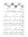
- an alternating current (AC) signalcomprises an envelope signal 1602 having a modulated waveform.
- the frequency of the modulated waveformmay vary to enable the transmission of data.
- the envelope power signal 1602may be a 60 Hertz signal which is used to power the outdoor light, while the data may be transmitted on higher frequency signals having different frequencies, enabling the transmission of control data between the switch 110 and the outdoor light 114 .
- the transmission of data using the alternating currentcould be implemented according to other data transmission means, such as varying the phase or frequency of the 60 Hertz power signal provided from the switch to the light to transmit the data.
- various bits 1702generated by an encoder of the switch or outdoor light, may be transmitted according to a digital data transmission protocol.
- the datamay be low voltage data signals transmitted at a different frequency that the AC signal which is used to power the outdoor light.
- the DC signalmay be filtered and decoded, as is well known in the art.
- a simple data frame for transmitting a mode control signalis shown.
- the frame according to the embodiment of FIG. 18comprises a header 1802 followed by a mode control signal 1804 and a footer 1806 .
- a headerin general may be used to provide a start of frame indicator and may include information indicating that the control signal is being sent from a certain element of the outdoor light arrangement (e.g. the switch 110 or the outdoor light 114 ).
- the mode control signalwill indicate the mode in which the outdoor light should operate.
- a footermay be included to provide an end of frame indication.
- an angle setting 1902 and a time 1904could be included in the frame to enable the operation of the user interface of FIGS. 2-5 .
- an address 2002may be included to provide a destination address for the frame.
- an on delay value 2102 and an off time value 2104could be included to enable an outdoor light arrangement having an ambient light sensor.
- a sensor status signalmay be provided.
- the sensor status signalmay indicate that a motion detector has detected the motion of an object, or that a certain ambient light condition has been detected, for example.
- FIG. 23a program screen enabling the entry of timing characterization data by a computer for implementing a light timer is shown.
- the program screens of FIGS. 17-23are provided on a display of a computer in response to operating a computer program stored on a memory of the computer (or other computer-readable storage medium such as a CR-ROM). Data entered on the various program screens of the computer program are stored on the portable memory device which may then be used by the switch as described above.
- a USB portable memory devicemay be inserted in a USB port of a computer to enable entering the timing characterization data and any sensor settings, and then removed and inserted into the switch as described above to load the into the switch 110 .
- the program for storing the timing characterization datamay be stored on the portable memory device, and when the data file on the portable memory device is opened, the program for storing the timing characterization data will be automatically opened. Accordingly, a portable memory device provided with the switch when it is purchased could provide all of the necessary elements to configure and operate the switch.
- the timing characterization datamay comprise varying amounts of data, but comprises at least one on/off setting for a switch. As will be described in more detail below, the timing characterization data may comprises a plurality of sets of data, including different sets for standard time and daylight savings time. According to some embodiments, the timing characterization data may include a current time and date entered by a user on the computer program. As will be described in more detail below, the current date entered by the user may be used to determine whether to apply a certain set of timing characterization data, such as a set of data for daylight savings time. Because a memory of the switch may comprise a memory having calendar information, such as future dates for daylight savings time, the current date would be used by a control circuit to determine which set of timing data would be used.
- a program screen 2302comprises a main screen which enables the entry of the minimal amount of information necessary to operate the switch.
- An on/off field 2304comprises an on time and an off time for each day of the week, where each on time and off time has an AM and PM setting. The numbers may be entered by highlighting the current number for a given time, and entering the desired number on the keypad of the computer, for example.
- a customization field 2306enables customization of the entry program.
- the customization fieldwill not only ease entry of data in the program screen 2302 , but also provide a more desirable performance of the switch. For example, a user may be able to select an option to repeat an entry for every day of the week. If the user selects that option before entering data, the on and off times for Tuesday through Sunday will automatically be entered to match the times entered for Monday. A user could also select an option for repeating Monday-Friday and/or repeating Saturday and Sunday. A user may select an option to enable automatically setting a daylight savings time feature.
- the daylight saving time featurecould change the time to daylight savings time automatically (based upon a calendar stored in a memory of the switch), and may implement the timer according to daylight saving time characterization data if available.
- a usermay select a staggered on/off timing feature.
- the staggered on/off timing featurewill stagger the times that the light is turned on and off relative to the stored time.
- the on and off timesmay be staggered by a varying number of minutes from 1 minute to 15 minutes, for example, and would preferably be performed randomly.
- no actuatorsare provided for entering the current time or date. Accordingly, the current time and date must be entered in a field 2308 on the profile screen 2302 .
- the userwould preferably set the current time just before the timing characterization data is saved, so that the user could then just insert the portable memory device into the switch to store the timing characterization data.
- the computer programwould prompt a user to enter the current time and date after the user attempts to finalize the data.
- actuators for entering current time and date informationcould be provided on the user interface.
- the profile screen 2302could further include an optional field 2309 enabling a user to manually set dates for applying a certain set of timing characterization data, such as daylight savings timing characterization data. That is, the user could enter a first date indicating the date upon which the daylight savings time timing characterization data should be applied and a second data indicating when daylight savings time should end and the standard time timing characterization data should be applied.
- a certain set of timing characterization datasuch as daylight savings timing characterization data. That is, the user could enter a first date indicating the date upon which the daylight savings time timing characterization data should be applied and a second data indicating when daylight savings time should end and the standard time timing characterization data should be applied.
- daylight savings time timing characterization datawill automatically be selected by a control circuit of the switch between the on and off dates entered in the field 2309 . Accordingly, if the dates are entered in the field 2309 , a daylight savings time actuator would not be necessary on a user interface of the switch.
- sensor datacould be entered in field 2310 . More particularly, a motion detection angle setting or on time could be entered as shown. According to the embodiment of FIG. 24 , sensor data for a switch enabling a low ambient light mode could be entered on a profile screen 2402 having a field 2404 for receiving an on delay value and one of two off time values as shown.
- FIG. 25a program screen enabling the entry of advanced settings of timing characterization data by a computer for implementing a light timer is shown.
- a program screen 2502allows a user to select whether the same number of settings will be provided for each day of the week, Monday-Friday, or Saturday and Sunday in a field 2504 . The user would then enter the appropriate data in a field 2506 . As in the program field 2302 , selecting one of the options in field 2504 would enable a user to reduce the number of settings that would need to be entered. A user would then select a next field 2508 .
- a program screen 2602enables the entry of timing characterization data for a plurality of on/off periods for implementing a light timer during Monday-Friday in a field 2604 . Because two settings were entered in the program screen 2508 for Monday-Friday, two settings are provided in the program screen 2602 . A user may also go back to a previous screen by selecting the back actuator 2606 . Only a single entry is then shown in the program screen 2702 , as shown in FIG. 27 . After selecting a finish actuator 2706 , the user may then use the portable memory device in the switch. As set forth above, the user may be prompted to enter or verify the correct time before finally saving all of the data.
- a usercan set data for daylight savings time when setting other characterization data.
- daylight saving times dataWhen daylight saving times data is entered, the daylight savings data will be used during established periods for daylight savings time.
- a daylight savings time datawould be applied when a daylight saving time actuator is moved to the on position, indicating that the daylight savings time data should be applied. If dates for applying daylight savings time timing characterization data were entered or calendar dates associated with daylight savings times stored in a memory of the switch, daylight savings time data could only be used during those periods.
- the switchwould only utilize daylight savings time characterization data when the current date is within an established daylight savings period, as established by on/off dates of daylight savings times or calendar information stored in a memory of the switch. If no daylight savings time actuator is provided on the switch, the switch may automatically apply daylight savings time data whenever the automatic daylight savings time option is selected, such as on the program screen 1702 and the current time is within the established period for daylight savings time.
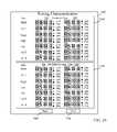
- program screensenable the entry multiple settings of timing characterization data when implementing a light timer according to an embodiment of the present invention. Similar to the embodiment of FIG. 21 , the embodiment of FIGS. 29A and 29B enable multiple settings, but the settings may be for different switches. For example, an A setting may be for a switch that is used for the front of the house, a B setting may be used for a switch that is used for the back of the house, a C setting may be used for a switch for an indoor light on a first floor, and a D setting may be used for a switch for an indoor light on a second floor.
- an A settingmay be for a switch that is used for the front of the house
- a B settingmay be used for a switch that is used for the back of the house
- a C settingmay be used for a switch for an indoor light on a first floor
- a D settingmay be used for a switch for an indoor light on a second floor.
- the usercould set the A-D settings for any category of timing characterization, such as a vacation setting, a school year setting, a summer setting, etc.
- a single portable memory devicecould be used to load timing characterization data for multiple switches.
- providing multiple settings on the portable memory deviceenables a flexible use of a given switch without having to reload timing characterization data. That is, one of the four settings designated as settings A-D could be selected by an actuator on the user interface for the switch 110 .
- the portable memory devicecomprises a proprietary memory device. While any memory device may be used, a proprietary memory device may prevent the switch from accessing incorrect data.
- the proprietary memory devicecomprises a single file which may only be opened on a computer by a program provided by the manufacturer of the switch for storing the data (or by the control circuit of the switch for implementing the data). The name of the data file could not be changed, and only data associated with fields accessible by the user could be entered or changed by the user.
- the portable memory devicemay also contain the computer program necessary to enter the timing characterization data. Accordingly, by “double-clicking” on the timing characterization data file, the computer program necessary to enter the timing characterization data will automatically open the timing characterization data file, enabling a user to set or change desired timing characterization data.
- FIGS. 30-35flow charts show the operation of the switch 110 according to various embodiments.
- the methods of FIGS. 30-35may be implemented as described in FIGS. 1-29 as shown and described, or other suitable circuits. While particular steps of the methods are shown, it should be understood that additional steps could be implemented as described in reference to FIGS. 1-29 .
- a flow chart of FIG. 30shows a method of operating an outdoor light having a motion detector according to an embodiment of the present invention. It is determined whether a mode actuator of a user interface at light switch positioned in a motion detection mode of an outdoor light at a step 3002 . If not, the light is operated in a normal on or off mode at a step 3004 .
- a selection made at the user interface to set a detection angle of the motion detector of the outdoor lightis detected at a step 3006 .
- a selection made at the user interface to set an on time for the outdoor light after motionis detected by the motion detector at a step 3008 . It is then determined whether motion is detected within the detection angle by the motion detector at a step 3010 . If so, the outdoor light is turned on for the selected on time at a step 3012 . Otherwise, the mode actuator is again monitored at the step 3002 .
- FIG. 31a flow chart shows a method of operating a light having an ambient light detector according to an embodiment of the present invention. It is determined whether a mode actuator of a user interface is in a low ambient light mode for an outdoor light at a step 3102 . If not, the light is operated in a normal on or off mode at a step 3104 . Otherwise, a selection made at the user interface is detected to adjust an on time of the outdoor light at a step 3106 . A selection made at the user interface is then detected to adjust an off time of the outdoor light at a step 3108 . It is then determined whether a low ambient light condition is detected at dusk at a step 3110 . If so, the outdoor light is turned on based upon the selected on time and off time at a step 3112 . Otherwise, the mode actuator is again monitored at the step 3102 .
- FIG. 32a flow chart shows a method of communicating control signals to a control circuit associated with an outdoor light according to an embodiment of the present invention.
- a change in a mode actuator or a control actuatoris detected at the user interface of a light switch at a step 3202 .
- a control signalis coupled from the switch to the outdoor light at a step 3204 .
- the control signalis decoded at a step 3206 .
- the power applied to the outdoor lightis controlled, by a control circuit at the outdoor light, in response to the control signal at a step 3208 .
- the method of FIG. 32finds particular application with the embodiment of the user interface of FIGS. 11 and 12 .
- FIG. 33a flow chart shows a method of communicating control signals between a control circuit associated with an outdoor light and a control circuit at an indoor user interface according to an embodiment of the present invention.
- a signal from the user interfaceis detected at a control circuit of the switch at a step 3304 .
- a signal from a sensor associated with the outdoor lightis detected at the control circuit of the switch at a step 3302 .
- the power applied to the outdoor lightis controlled, by a control circuit of the switch, in response to the signals from the light and from the user interface at a step 3306 .
- the method of FIG. 33finds particular application with the embodiment of the user interface of FIGS. 13 and 14 .
- FIG. 34a flow chart shows a method of implementing an outdoor light having an ambient light detector according to an embodiment of the invention.
- An outdoor lightis operated with an ambient light detector at a step 3402 . It is determined whether a delay in turning the outdoor light on near dusk desired at a step 3404 . If so, the outdoor light is turned on after a predetermined delay after detecting a low ambient light condition associated with dusk at a step 3406 . Otherwise, the outdoor light is turned on after detecting a low ambient light condition associated with dusk at a step 3408 . It is also determined whether an early off time for the outdoor light is desired near dawn at a step 3410 . If so, the outdoor light is turned off at a predetermined time before an estimated time for dawn at a step 3412 . Otherwise, the outdoor light is turned off after detecting a low ambient light condition associated with dawn at a step 3414 .
- FIG. 35a flow chart shows a method of enabling turning off an outdoor light having an ambient light detector before dawn according to an alternate embodiment of the invention.
- a time for dawn using an ambient light detector associated with an outdoor lightis detected on a predetermined day at a step 3502 .
- the detected time for dawnis stored in a memory associated with the outdoor light at a step 3504 .
- the outdoor light having the ambient light sensoris operated on a day after the predetermined day at a step 3406 .
- the lightis turned off before the stored detected time on the day after the predetermined day at a step 3508 .
- the outdoor lightmay be turned off according to an early off time as described above in reference to FIGS. 7 and 9 .
- the detected time for dawnis periodically updated in the memory at a step 3510 .
- the estimated time for dawnmay be updated daily or weekly, for example, to accommodate the change in sunrise which varies with the seasons.
- FIGS. 36-40methods of implementing a timer are shown.
- the methods of FIGS. 36-40may be implemented using any of the switches or the program screens of the computer program as described, for example. Although various steps of the methods are described, it should be understood that additional steps could be implemented according to other features and functionality of the timers and program screens as described. It should further understood that the various methods, although shown in different methods, may be employed together.
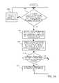
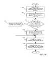
- a flow chartshows a method of generating timing characterization data according to an embodiment of the present invention. It is first determined whether a portable memory device has a program for entering timing characterization data at a step 3602 . If not, it is then determined whether a disk is available for enabling access to timing characterization for a portable memory device at a step 3604 . If not, a program is downloaded to a computer, such as through an internet connection by way of the communication network at a step 3606 . The program is loaded on the computer at a step 3608 , and is opened at a step 3610 . Timing characterization data are set at a step 3612 . It is then determined whether there are advanced features which may be set at a step 3612 .
- timing characterization dataare set at a step 3616 . It is then determined whether multiple settings are required at a step 3618 . If so, the timing characterization data for the next settings are set at a step 3620 . If not, the timing characterization data are stored at a step 3622 .
- Timing characterization datais stores on a portable memory device at a step 3702 . It is then determined whether the timing characterization data needs to be loaded or reloaded at a step 3704 . It is also determined whether the timing characterization data needs to be changed at a step 3706 . If so, new data associated with timing characterization data is stored at a step 3708 .
- a portable memory deviceis placed in the switch at a step 3710 . It is then determined whether a portable memory device is detected at a step 3712 . Access by a switch to data stored on portable memory device is enabled at a step 3714 . It is then determined whether the switch requires information by way of a user interface on the switch at a step 3716 . If so, data is received from the user interface at a step 3518 . The switch is then operated according to new data at a step 3720 .
- Timing characterization datais stored on a portable memory device at a step 3802 .
- a portable memory deviceis then placed into a switch at a step 3804 . It is then determined whether a switch requires using the portable memory to operate at a step 3806 . If not, the timing characterization data is downloaded to an internal memory at a step 3808 . Otherwise, a portable memory device is retained in switch at a step 3810 .
- the timing characterization datais accessed at a step 3812 .
- the switchis operated according to the timing characterization data at a step 3814 .
- FIG. 39a flow chart shows a method of configuring multiple switches according to an embodiment the present invention.
- Timing characterization datais stored on a portable memory device at a step 3902 . It is then determined whether the portable memory device is detected in the switch at a step 3904 . Timing characterization data is transferred to an internal memory of the switch at a step 3906 . The portable memory device is removed at a step 3908 . Settings are selected on a user interface of the device as necessary at a step 3710 . It is then determined whether additional switches need to be configured at a step 3912 . If so, the portable memory device is inserted into another switch at a step 3914 . The switch or switches are then operated according to data from the portable memory device at a step 3916 .
Landscapes
- Circuit Arrangement For Electric Light Sources In General (AREA)
Abstract
Description
Claims (20)
Priority Applications (1)
| Application Number | Priority Date | Filing Date | Title |
|---|---|---|---|
| US14/519,267US11297709B2 (en) | 2011-02-01 | 2014-10-21 | Circuit arrangement for enabling motion detection to control an outdoor light |
Applications Claiming Priority (2)
| Application Number | Priority Date | Filing Date | Title |
|---|---|---|---|
| US13/018,475US9615428B2 (en) | 2011-02-01 | 2011-02-01 | Arrangement for an outdoor light enabling motion detection |
| US14/519,267US11297709B2 (en) | 2011-02-01 | 2014-10-21 | Circuit arrangement for enabling motion detection to control an outdoor light |
Related Parent Applications (1)
| Application Number | Title | Priority Date | Filing Date |
|---|---|---|---|
| US13/018,475DivisionUS9615428B2 (en) | 2011-02-01 | 2011-02-01 | Arrangement for an outdoor light enabling motion detection |
Publications (2)
| Publication Number | Publication Date |
|---|---|
| US20150173158A1 US20150173158A1 (en) | 2015-06-18 |
| US11297709B2true US11297709B2 (en) | 2022-04-05 |
Family
ID=46577214
Family Applications (2)
| Application Number | Title | Priority Date | Filing Date |
|---|---|---|---|
| US13/018,475Expired - Fee RelatedUS9615428B2 (en) | 2011-02-01 | 2011-02-01 | Arrangement for an outdoor light enabling motion detection |
| US14/519,267Active2031-05-23US11297709B2 (en) | 2011-02-01 | 2014-10-21 | Circuit arrangement for enabling motion detection to control an outdoor light |
Family Applications Before (1)
| Application Number | Title | Priority Date | Filing Date |
|---|---|---|---|
| US13/018,475Expired - Fee RelatedUS9615428B2 (en) | 2011-02-01 | 2011-02-01 | Arrangement for an outdoor light enabling motion detection |
Country Status (1)
| Country | Link |
|---|---|
| US (2) | US9615428B2 (en) |
Families Citing this family (36)
| Publication number | Priority date | Publication date | Assignee | Title |
|---|---|---|---|---|
| US9615428B2 (en)* | 2011-02-01 | 2017-04-04 | John Joseph King | Arrangement for an outdoor light enabling motion detection |
| US20150264776A1 (en)* | 2012-09-24 | 2015-09-17 | Petra Solar, Inc. | Distributed street lights energy remote monitoring, command and control |
| WO2014130997A1 (en)* | 2013-02-25 | 2014-08-28 | International Development LLC | Luminaire having multiple sensors and independantly-controllable sources |
| US9226373B2 (en) | 2013-10-30 | 2015-12-29 | John Joseph King | Programmable light timer and a method of implementing a programmable light timer |
| DE102014103197A1 (en) | 2014-03-11 | 2015-09-17 | Herbert Waldmann Gmbh & Co. Kg | Luminaire for illuminating a building area, in particular an office |
| US9584724B2 (en)* | 2014-05-22 | 2017-02-28 | Raytheon Company | Ultra-wide field of view seeker |
| US10212782B2 (en)* | 2015-04-30 | 2019-02-19 | William F. Harris, Jr. | Device and method for mode control of wildlife-friendly lighting |
| CA3021065A1 (en) | 2016-03-07 | 2017-09-14 | William LARK Jr. | Intelligent lighting control apparatuses, systems, and methods |
| US10401007B1 (en)* | 2016-07-19 | 2019-09-03 | Cooper Technologies Company | Integrated sensing and control of light fixtures |
| US12093004B1 (en) | 2017-04-01 | 2024-09-17 | Smart Power Partners LLC | In-wall power adapter and method of implementing an in-wall power adapter |
| US10996645B1 (en) | 2017-04-01 | 2021-05-04 | Smart Power Partners LLC | Modular power adapters and methods of implementing modular power adapters |
| US10530597B1 (en) | 2017-04-01 | 2020-01-07 | Smart Power Partners LLC | System for controlling a plurality of power switches configured to apply power to devices |
| US12027968B2 (en) | 2017-04-01 | 2024-07-02 | John J. King | Power adapters and methods of implementing a power adapter |
| US10727731B1 (en) | 2017-04-01 | 2020-07-28 | Smart Power Partners, LLC | Power adapters adapted to receive a module and methods of implementing power adapters with modules |
| CN109168241B (en)* | 2018-10-30 | 2020-08-25 | 重庆辉烨通讯技术有限公司 | Intelligent control method, system and server |
| US10948965B2 (en) | 2018-12-31 | 2021-03-16 | Ecolink Intelligent Technology, Inc. | User-configurable person detection system, method and apparatus |
| US11227476B2 (en)* | 2019-03-13 | 2022-01-18 | Ecolink Intelligent Technology, Inc. | Auto-configurable motion/occupancy sensor |
| US10958020B1 (en) | 2019-06-30 | 2021-03-23 | Smart Power Partners LLC | Control attachment for an in-wall power adapter and method of controlling an in-wall power adapter |
| US11043768B1 (en) | 2019-06-30 | 2021-06-22 | Smart Power Partners LLC | Power adapter configured to provide power to a load and method of implementing a power adapter |
| US11219108B1 (en) | 2019-06-30 | 2022-01-04 | Smart Power Partners LLC | Power adapter arrangement and method of implementing a power adapter arrangement |
| US10965068B1 (en) | 2019-06-30 | 2021-03-30 | Smart Power Partners LLC | In-wall power adapter having an outlet and method of controlling an in-wall power adapter |
| US12164350B1 (en) | 2019-06-30 | 2024-12-10 | Smart Power Partners LLC | Power adapter configured to provide power to a load |
| US10917956B1 (en) | 2019-06-30 | 2021-02-09 | Smart Power Partners LLC | Control attachment configured to provide power to a load and method of configuring a control attachment |
| US10938168B2 (en) | 2019-06-30 | 2021-03-02 | Smart Power Partners LLC | In-wall power adapter and method of controlling the application of power to a load |
| US11201444B1 (en) | 2019-06-30 | 2021-12-14 | Smart Power Partners LLC | Power adapter having contact elements in a recess and method of controlling a power adapter |
| US10958026B1 (en) | 2019-06-30 | 2021-03-23 | Smart Power Partners LLC | Contactless thermometer for an in-wall power adapter |
| US11231730B1 (en) | 2019-06-30 | 2022-01-25 | Smart Power Power LLC | Control attachment for a power adapter configured to control power applied to a load |
| US11264769B1 (en) | 2019-06-30 | 2022-03-01 | Smart Power Partners LLC | Power adapter having contact elements in a recess and method of controlling a power adapter |
| US12045071B1 (en) | 2019-06-30 | 2024-07-23 | Smart Power Partners LLC | In-wall power adapter having an outlet |
| US11579640B1 (en) | 2019-06-30 | 2023-02-14 | Smart Power Partners LLC | Control attachment for an in-wall power adapter |
| US11189948B1 (en) | 2019-06-30 | 2021-11-30 | Smart Power Partners LLC | Power adapter and method of implementing a power adapter to provide power to a load |
| US11460874B1 (en) | 2019-06-30 | 2022-10-04 | Smart Power Partners LLC | In-wall power adapter configured to control the application of power to a load |
| US12066848B1 (en) | 2019-06-30 | 2024-08-20 | Smart Power Partners LLC | In-wall power adaper adapted to receive a control attachment and method of implementing a power adapter |
| US11650102B2 (en) | 2021-07-22 | 2023-05-16 | Ecolink Intelligent Technology, Inc. | Adjustable dwell time for motion detector based on activity |
| US12160074B2 (en) | 2021-11-03 | 2024-12-03 | Smart Power Partners LLC | In-wall power adapter having a switch and a recess adapted to receive a control module |
| GB2619738B (en)* | 2022-06-15 | 2024-09-18 | All Led Ltd | Motion sensor light apparatus |
Citations (279)
| Publication number | Priority date | Publication date | Assignee | Title |
|---|---|---|---|---|
| US2397688A (en) | 1944-04-12 | 1946-04-02 | Stephen B Osinski | Electric outlet box |
| US2908743A (en) | 1956-11-30 | 1959-10-13 | Robert T Premoshis | Electrical outlet |
| US3588489A (en) | 1968-04-04 | 1971-06-28 | Sierra Electric Inc | Illuminated electrical device |
| US3609647A (en) | 1968-12-19 | 1971-09-28 | Angelo Castellano | Electrical receptacle |
| US3879101A (en) | 1973-12-04 | 1975-04-22 | George T Mckissic | Electric Plug-In Module |
| US3895225A (en) | 1974-03-29 | 1975-07-15 | Sola Basic Ind Inc | Illuminated receptacle with removable lens |
| US4117258A (en) | 1976-05-21 | 1978-09-26 | Benjamin Shanker | Modular electric light switch assembly |
| US4148092A (en) | 1977-08-04 | 1979-04-03 | Ricky Martin | Electronic combination door lock with dead bolt sensing means |
| US4279012A (en) | 1978-10-23 | 1981-07-14 | Massachusetts Microcomputers, Inc. | Programmable appliance controller |
| US4349748A (en) | 1979-03-21 | 1982-09-14 | Dynascan Corporation | Timer and power control system |
| US4357665A (en) | 1979-12-27 | 1982-11-02 | Butler Manufacturing Company | Programmable electronic real-time load controller providing demand limit control |
| US4521843A (en) | 1982-08-16 | 1985-06-04 | Intermatic Incorporated | Programmable wall switch for controlling lighting times and loads |
| US4521869A (en) | 1982-04-02 | 1985-06-04 | The Babcock & Wilcox Company | Program timer control |
| US4546419A (en) | 1984-11-05 | 1985-10-08 | Johnson Kelli J | Wall receptacle recessed box contained light intensity on/off controlled night light system |
| US4631354A (en) | 1985-05-13 | 1986-12-23 | Harvey Hubbell Incorporated | Cover assembly for electrical outlet box |
| US4636914A (en) | 1984-11-28 | 1987-01-13 | Ave S.P.A. | Outlet box with removable self-contained device |
| US4677541A (en) | 1984-09-24 | 1987-06-30 | Rauland-Borg Corporation | Programmable clock |
| US4893062A (en) | 1987-04-21 | 1990-01-09 | Lutron Electronics Co., Inc. | Wall box dimming system and face plate and switch assembly therefor |
| US4973801A (en)* | 1990-01-10 | 1990-11-27 | Burle Technologies, Inc. | Interlocked motion detector wall switch |
| US5046157A (en) | 1988-02-03 | 1991-09-03 | Smith Stephen W | Time control device for appliances |
| US5105336A (en) | 1987-07-29 | 1992-04-14 | Lutron Electronics Co., Inc. | Modular multilevel electronic cabinet |
| US5148159A (en) | 1989-04-26 | 1992-09-15 | Stanley Electronics | Remote control system with teach/learn setting of identification code |
| US5160853A (en) | 1988-08-08 | 1992-11-03 | Honeywell Inc. | Electronic timer switch with time tracker |
| US5191265A (en) | 1991-08-09 | 1993-03-02 | Lutron Electronics Co., Inc. | Wall mounted programmable modular control system |
| US5229925A (en) | 1991-07-19 | 1993-07-20 | Valcom, Inc. | Modular front panel and enclosure for electronic apparatus |
| US5399806A (en) | 1992-02-21 | 1995-03-21 | Olson; Richard A. | Modular electrical wiring system |
| US5442177A (en)* | 1992-09-25 | 1995-08-15 | Pace Control Technologies, Inc. | Dusk delay system for outdoor motion detection |
| US5444456A (en) | 1991-05-23 | 1995-08-22 | Matsushita Electric Industrial Co., Ltd. | LED display apparatus |
| US5471012A (en) | 1994-07-28 | 1995-11-28 | Geo Ventures | Electrical wire box apparatus |
| US5473517A (en) | 1995-01-23 | 1995-12-05 | Blackman; Stephen E. | Emergency safety light |
| US5528229A (en) | 1993-10-29 | 1996-06-18 | Hunter Fan Company | Thermostatically controlled remote control for a ceiling fan and light |
| US5586048A (en) | 1992-06-16 | 1996-12-17 | Vigilight Inc. | Intelligent wall switch |
| US5610853A (en) | 1992-12-16 | 1997-03-11 | Ricoh Company, Ltd. | Ferroelectric material, and semiconductor memory, optical recording medium and micro-displacement control device using the ferroelectric material |
| US5666017A (en) | 1994-03-22 | 1997-09-09 | Tailored Lighting Inc. | Daylight lamp |
| US5793125A (en) | 1991-02-25 | 1998-08-11 | Tarng; Min Ming | Smart integrated socket automation system |
| US5805444A (en) | 1996-05-22 | 1998-09-08 | Bellsouth Corporation | Method and system for providing a temporal interface for use in implementing a process |
| US5813873A (en) | 1995-09-07 | 1998-09-29 | Mcbain; Theodore | Electrical outlet safety cover |
| US5831391A (en) | 1995-08-17 | 1998-11-03 | Mackay; Iain N. B. | Timer controlled outdoor ground lighting system with intruder detection |
| US5857113A (en) | 1994-06-10 | 1999-01-05 | Harris Corporation | Multiprocessor system assigning system function to each processor in accordance with delay function and maintaining the system function assignment after the system is rebooted |
| US5867099A (en) | 1997-11-24 | 1999-02-02 | Keeter; Daniel R. | Motion sensing, lighting and alarming system |
| US5872513A (en) | 1996-04-24 | 1999-02-16 | The Chamberlain Group, Inc. | Garage door opener and wireless keypad transmitter with temporary password feature |
| US5898397A (en) | 1996-01-16 | 1999-04-27 | Stanley Home Automation | Remote control transmitter and method of operation |
| US5940007A (en) | 1996-02-24 | 1999-08-17 | Mercedes-Benz Ag | Remote control system for motor vehicle related devices |
| US5949200A (en) | 1996-07-30 | 1999-09-07 | Lutron Electronics Co., Inc. | Wall mountable control system with virtually unlimited zone capacity |
| US5962989A (en) | 1995-01-17 | 1999-10-05 | Negawatt Technologies Inc. | Energy management control system |
| US5990471A (en) | 1997-02-17 | 1999-11-23 | Sharp Kabushiki Kaisha | Motion detection solid-state imaging device |
| US6000807A (en) | 1997-04-25 | 1999-12-14 | Moreland; Gregory B. | Switch cover plate providing automatic emergency lighting |
| US6026165A (en) | 1996-06-20 | 2000-02-15 | Pittway Corporation | Secure communications in a wireless system |
| US6045232A (en) | 1998-02-16 | 2000-04-04 | Buckmaster; Clifford Thoren | Apparatus for providing emergency and night lighting |
| US6121889A (en) | 1997-04-24 | 2000-09-19 | Intermatic Incorporated | In-wall electronic timer |
| US6120165A (en) | 1996-07-10 | 2000-09-19 | Solar Wide Industrial Ltd. | Outdoor solar lamp |
| US6160377A (en) | 1997-10-20 | 2000-12-12 | Fujitsu Limited | Battery charging device and method and electronic device |
| US6169377B1 (en) | 1996-03-13 | 2001-01-02 | Lutron Electronics Co., Inc. | Lighting control with wireless remote control and programmability |
| US6188182B1 (en) | 1996-10-24 | 2001-02-13 | Ncon Corporation Pty Limited | Power control apparatus for lighting systems |
| US6335852B1 (en) | 1996-12-20 | 2002-01-01 | James Nimmo | Programmable fuse and programming device for timer |
| US20020038981A1 (en) | 1999-09-28 | 2002-04-04 | Paul C. Brown | Modular emergency stop relay system |
| US6376770B1 (en) | 2000-02-28 | 2002-04-23 | Douglas Hyde | Quick connecting universal electrical box and wiring system |
| US6388399B1 (en) | 1998-05-18 | 2002-05-14 | Leviton Manufacturing Co., Inc. | Network based electrical control system with distributed sensing and control |
| US20020086567A1 (en) | 2000-05-08 | 2002-07-04 | Cash Ronald G. | Smart modular receptacle and system |
| US6442452B1 (en) | 1997-03-27 | 2002-08-27 | Siemens Aktiengesellschaft | Control apparatus for carrying out switching operations in a switchgear assembly |
| US6466826B1 (en)* | 1999-06-28 | 2002-10-15 | Hubbell Incorporated | Apparatus and method for providing bypass functions for a motion sensor switch |
| US20020154652A1 (en) | 2001-04-24 | 2002-10-24 | Matsushita Electric Works, Ltd. | Programmable timer unit for use in a remote control load management system |
| US6476523B1 (en) | 2000-03-17 | 2002-11-05 | Kathleen L. Lee | Electronic clock and timed outlet strip |
| DE10223168A1 (en)* | 2001-06-05 | 2003-01-09 | Rolf Arnold | Switch insert for installation in conventional flush-mounted switch sockets, has outside lamp connected with in-built external movement alarm using single switch insert, and includes four switching possibilities |
| US20030025400A1 (en) | 2001-08-06 | 2003-02-06 | Hall Christopher R. | Method and system for controlling one or more apparatus based on a geographic location |
| US6563430B1 (en) | 1998-12-11 | 2003-05-13 | Koninklijke Philips Electronics N.V. | Remote control device with location dependent interface |
| US6617511B2 (en) | 2000-01-07 | 2003-09-09 | James Douglas Schultz | Prewired electrical apparatus having quick connect components |
| US6644557B1 (en) | 2002-03-25 | 2003-11-11 | Robert A Jacobs | Access controlled thermostat system |
| US6658303B2 (en) | 1999-12-15 | 2003-12-02 | Matsushita Electric Works, Ltd. | Program timer |
| US6660948B2 (en) | 2001-02-28 | 2003-12-09 | Vip Investments Ltd. | Switch matrix |
| US6664468B2 (en) | 2000-01-31 | 2003-12-16 | Legrand | Modular electrical appliances and housing comprising same |
| US6708135B2 (en) | 2001-01-05 | 2004-03-16 | Abb, Inc. | Method for programming timer to execute timing operations |
| US6737576B1 (en) | 2003-05-16 | 2004-05-18 | Thomas & Betts International, Inc. | Electrical box assembly |
| US6740831B2 (en) | 2000-10-13 | 2004-05-25 | Maschinenfabrik Reinhausen Gmbh | Mechanical switching contact |
| US6753842B1 (en) | 1999-12-20 | 2004-06-22 | Qualcomm Incorporated | System and method for backlighting control in a wireless communication device |
| US6767245B2 (en) | 2000-01-27 | 2004-07-27 | Leviton Manufacturing Co., Inc. | Modular GFCI receptacle |
| US20040159531A1 (en) | 2002-09-19 | 2004-08-19 | Hoffman Lawrence Andrew | Modular contact switch |
| US6805469B1 (en) | 2003-05-03 | 2004-10-19 | R A Barton | Concealed safety lighting device |
| US20040218379A1 (en) | 2003-05-03 | 2004-11-04 | Mr. Robert Barton | Concealed Safety Lighting Device |
| US20040260853A1 (en) | 2003-04-11 | 2004-12-23 | Samsung Electronics Co., Ltd. | Computer system and method of setting an interface card therein |
| USD500687S1 (en) | 2004-05-03 | 2005-01-11 | Randall L. Morrison | Wall mountable timer switch |
| US20050075741A1 (en) | 2003-08-08 | 2005-04-07 | Trw Automotive Electronics & Components Gmbh & Co. Kg | Modular switch and control system for use in a motor vehicle |
| US6888323B1 (en) | 2002-09-25 | 2005-05-03 | The Watt Stopper, Inc. | Light management system device and method |
| US6903650B2 (en) | 2002-05-20 | 2005-06-07 | Wayne-Dalton Corp. | Operator with transmitter storage overwrite protection and method of use |
| US20050136972A1 (en) | 2003-12-09 | 2005-06-23 | Smith Derek M. | Plug-in network appliance |
| US6920843B1 (en) | 2002-09-09 | 2005-07-26 | William E. Wilson | Programmable water heater |
| US6927541B2 (en)* | 2002-06-14 | 2005-08-09 | Eml Technologies Llc | Multimode motion-activated lighting |
| US6943296B2 (en) | 2003-12-03 | 2005-09-13 | Bellsouth Intellectual Property Corp. | USB wall plate |
| US6958584B2 (en) | 2002-12-05 | 2005-10-25 | Yazaki Corporation | Lamp driving apparatus and method for driving lamp |
| US20050242753A1 (en) | 2004-05-03 | 2005-11-03 | Morrison Randall L | Automatic and manual wall switch device |
| US20050253538A1 (en) | 2004-03-29 | 2005-11-17 | Suresh Shah | Remotely controlled lighting system and controller switch for operation on same |
| US6967565B2 (en) | 2003-06-27 | 2005-11-22 | Hx Lifespace, Inc. | Building automation system |
| US20060012317A1 (en) | 2004-07-14 | 2006-01-19 | Shin-Yung Chiu | RF remote dimmer controller |
| US20060012312A1 (en) | 2004-07-19 | 2006-01-19 | Intersil Americas Inc. | Phase shift modulation-based control of amplitude of AC voltage output produced by double-ended DC-AC converter circuitry for powering high voltage load such as cold cathode fluorescent lamp |
| US6989489B1 (en) | 2003-01-09 | 2006-01-24 | Pass & Seymour, Inc. | Modular device wall plate |
| US20060038499A1 (en) | 2004-08-18 | 2006-02-23 | Ming-Hsiang Yeh | Monitoring apparatus with connector |
| US20060049914A1 (en) | 2001-08-09 | 2006-03-09 | The Chamberlain Group, Inc. | Method and apparatus for a rolling code learning transmitter |
| US20060074497A1 (en) | 2004-09-29 | 2006-04-06 | Pollin Robert E | Methods, systems, and articles of manufacture for providing a timing apparatus with an almanac memory |
| US7039397B2 (en) | 2003-07-30 | 2006-05-02 | Lear Corporation | User-assisted programmable appliance control |
| US7047092B2 (en) | 2003-04-08 | 2006-05-16 | Coraccess Systems | Home automation contextual user interface |
| US20060125324A1 (en) | 2004-12-15 | 2006-06-15 | Advanced Timer Technologies Limited | Timer switch |
| US20060146652A1 (en)* | 2005-01-03 | 2006-07-06 | Sdi Technologies, Inc. | Sunset timer |
| US7081009B2 (en) | 2002-05-23 | 2006-07-25 | Protectconnect | Electrical distribution functional module |
| US20060186991A1 (en) | 2005-02-23 | 2006-08-24 | The Chamberlain Group, Inc. | System and method for performing transmitter function mapping |
| US7106168B2 (en) | 2004-01-12 | 2006-09-12 | Overhead Door Corporation | Menu driven wall console with LED indicators for garage door operator |
| US20060202851A1 (en) | 2005-03-12 | 2006-09-14 | Cash Audwin W | Handheld programmer for lighting control system |
| US20060239123A1 (en) | 2004-02-27 | 2006-10-26 | Duteck Industrial Co., Ltd. | Daylight saving time automatic adjustment method and timepiece using same |
| US20060250745A1 (en) | 2005-05-05 | 2006-11-09 | Alan Butler | Programmable power controller |
| US7155305B2 (en) | 2003-11-04 | 2006-12-26 | Universal Electronics Inc. | System and methods for home appliance identification and control in a networked environment |
| US7160147B1 (en) | 2006-04-07 | 2007-01-09 | Stephan Gerard D | Electrical connection system |
| US7167777B2 (en) | 2003-11-04 | 2007-01-23 | Powerweb Technologies | Wireless internet lighting control system |
| US20070109781A1 (en) | 2005-11-16 | 2007-05-17 | Shin-Yung Chiu | Wireless remote control porch light |
| US20070109763A1 (en) | 2003-07-02 | 2007-05-17 | S.C. Johnson And Son, Inc. | Color changing outdoor lights with active ingredient and sound emission |
| US7248201B2 (en) | 2005-03-07 | 2007-07-24 | War Corporation | Key fob with automatic cover release |
| US20070183270A1 (en) | 2006-01-31 | 2007-08-09 | Koichiro Sakamoto | Timer circuit |
| US7255596B2 (en) | 2003-09-10 | 2007-08-14 | Pyrros Chrestos T | Modular electrical receptacle |
| US20070188323A1 (en) | 2006-01-26 | 2007-08-16 | Microsoft Corporation | Motion Detection Notification |
| US7258064B2 (en) | 2002-09-04 | 2007-08-21 | Prince Castle, Inc. | Food product timing system |
| US20070206375A1 (en) | 2000-04-24 | 2007-09-06 | Color Kinetics Incorporated | Light emitting diode based products |
| US7273392B2 (en) | 2004-07-29 | 2007-09-25 | Dan Fields | Universal electrical module |
| US7285721B1 (en) | 2003-12-02 | 2007-10-23 | Pass & Seymour, Inc. | Modular terminal device |
| US20080001551A1 (en) | 2003-07-02 | 2008-01-03 | S.C. Johnson & Son, Inc. | Adapter for Light Bulbs Equipped with Volatile Active Dispenser and Light Emitting Diodes |
| US7345998B2 (en) | 2004-12-15 | 2008-03-18 | Smart Labs, Inc. | Mesh network of intelligent devices communicating via powerline and radio frequency |
| US7357652B1 (en) | 2006-10-27 | 2008-04-15 | Leviton Manufacturing Company, Inc. | Modular wiring system with locking elements |
| US7362227B2 (en) | 2003-10-15 | 2008-04-22 | Walter Taehwan Kim | Anti-theft and security system for computers |
| US7360912B1 (en) | 2003-12-02 | 2008-04-22 | Pass & Seymour, Inc. | Electrical device with lamp module |
| US7365964B2 (en) | 2001-11-28 | 2008-04-29 | Donahue Iv William F | Modular power distribution unit, module for the power distribution unit, and method of using the same |
| US7375476B2 (en) | 2005-04-08 | 2008-05-20 | S.C. Johnson & Son, Inc. | Lighting device having a circuit including a plurality of light emitting diodes, and methods of controlling and calibrating lighting devices |
| US7374476B2 (en) | 2000-08-28 | 2008-05-20 | Micron Technology, Inc. | Method and apparatus for forming a planarizing pad having a film and texture elements for planarization of microelectronic substrates |
| US20080125888A1 (en) | 2006-09-22 | 2008-05-29 | Siemens Energy & Automation, Inc. | Offline configuration using USB download in an itegrated power distribution system |
| US7382100B2 (en) | 2004-01-07 | 2008-06-03 | Lutron Electronics Co., Inc. | Lighting control device having improved long fade off |
| US20080154652A1 (en) | 2006-12-21 | 2008-06-26 | Swiss Reinsurance Company | System and method for calculating damage as a result of natural catastrophes |
| US7400239B2 (en) | 2004-09-03 | 2008-07-15 | Simply Automated, Incorporated | Universal control apparatus and methods |
| US7403825B2 (en) | 2006-04-05 | 2008-07-22 | Juergen Nies | Programmable device with removable templates |
| US7405524B2 (en)* | 2002-09-25 | 2008-07-29 | The Watt Stopper Inc. | Light management system device and method |
| US20080229125A1 (en) | 2007-03-16 | 2008-09-18 | Tson-Yee Lin | Power managing method of a scheduling system and related scheduling system |
| US20080232810A1 (en) | 2007-03-19 | 2008-09-25 | Halfa Enterprise Co., Ltd. | Bluetooth-enabled infrared remote control |
| US7436132B1 (en) | 2002-09-25 | 2008-10-14 | The Watt Stopper Inc. | Multi-way sensor switch |
| US7439832B1 (en) | 2004-03-16 | 2008-10-21 | Pass & Seymour, Inc. | Electrical wiring device switch assembly and combination device with circuit protection component |
| US20080258644A1 (en) | 2007-04-23 | 2008-10-23 | Lutron Electronics Co., Inc. | Load Control Device Having A Modular Assembly |
| US20080265685A1 (en) | 2006-09-13 | 2008-10-30 | Lutron Electronics Co., Inc. | Multiple location electronic timer system |
| US20080278352A1 (en) | 2007-05-11 | 2008-11-13 | Sony Ericsson Mobile Communications Ab | Systems and methods for changing characters associated with keys |
| US7460930B1 (en) | 2004-05-14 | 2008-12-02 | Admmicro Properties, Llc | Energy management system and method to monitor and control multiple sub-loads |
| US7463148B2 (en) | 2005-01-21 | 2008-12-09 | Leen Monte A | Wireless motion activated light fixture base plate and kit |
| US20080309253A1 (en) | 2007-06-18 | 2008-12-18 | Canel Lighting Co., Ltd. | Apparatus For Remote Control Of Lights |
| US20090059603A1 (en) | 2007-08-30 | 2009-03-05 | Wireless Environment, Llc | Wireless light bulb |
| US7501941B2 (en) | 2006-01-13 | 2009-03-10 | Lites Out, Llc | Managing advertising devices |
| US20090066258A1 (en) | 2007-09-07 | 2009-03-12 | Streetlight Intelligence, Inc. | Streelight monitoring and control |
| US20090122571A1 (en) | 2007-11-11 | 2009-05-14 | Isaiah Monty Simmons | Smart Lights |
| US20090125682A1 (en) | 2007-11-12 | 2009-05-14 | Prince Castle, Inc. | Memory Card Programmable Timer Device and Method |
| US7575470B2 (en) | 2003-09-10 | 2009-08-18 | Pyrros Chrestos T | Modular electrical receptacle |
| US7579717B2 (en) | 2006-09-13 | 2009-08-25 | Lutron Electronics Co., Inc. | Wall-mountable timer for an electrical load |
| US20090225811A1 (en) | 2008-03-10 | 2009-09-10 | Axiometric, Llc | Remote Wireless Activation and Communication |
| US20090273433A1 (en) | 2005-03-12 | 2009-11-05 | Rigatti Christopher J | Method of automatically programming a new ballast on a digital ballast communication link |
| US7627313B2 (en) | 2003-12-22 | 2009-12-01 | Gigaset Communications Gmbh | Method, telecommunication system and telecommunication handset for wireless communication and telecommunication in a smart home environment |
| US20100025219A1 (en) | 2008-07-29 | 2010-02-04 | Milton Roy Company | System and method for membrane distillation with low reynolds numbers |
| US20100025210A1 (en) | 2008-07-29 | 2010-02-04 | Honeywell International Inc | Electric timer for controlling power to a load |
| US7663325B2 (en) | 2004-07-15 | 2010-02-16 | Lutron Electronics Co., Inc. | Programmable wallbox dimmer |
| US20100045205A1 (en) | 2005-06-30 | 2010-02-25 | Koninklijke Philips Electronics, N.V. | Remote color control device and lighting system |
| US20100052894A1 (en) | 2008-09-03 | 2010-03-04 | Steiner James P | Battery-powered occupancy sensor |
| US20100052487A1 (en) | 2008-08-29 | 2010-03-04 | Michael Stein | Frame for supporting keypad and other in-wall electronic components |
| US7683755B2 (en) | 2004-06-29 | 2010-03-23 | Leviton Manufacturing Corporation, Inc. | Control system for electrical devices |
| US7689875B2 (en) | 2002-04-25 | 2010-03-30 | Microsoft Corporation | Watchdog timer using a high precision event timer |
| US7694005B2 (en) | 2005-11-04 | 2010-04-06 | Intermatic Incorporated | Remote device management in a home automation data transfer system |
| US20100084996A1 (en) | 2007-03-29 | 2010-04-08 | Koninklijke Philips Electronics N.V. | Natural daylight mimicking system and user interface |
| US7734038B2 (en) | 2006-05-01 | 2010-06-08 | Ortronics, Inc. | Electrical receptacle with open corner region |
| US20100176744A1 (en) | 2009-01-09 | 2010-07-15 | Young Hwan Lee | Illumination Apparatus and Driving Method Thereof |
| US7767905B2 (en) | 2007-10-31 | 2010-08-03 | Meyer Mark H | Electrical apparatus having quick connect components |
| US7774648B2 (en) | 2007-05-02 | 2010-08-10 | Honeywell International Inc. | Microprocessor supervision in a special purpose computer system |
| US20100213875A1 (en) | 2009-02-26 | 2010-08-26 | Li-Chun Lai | Power Supply Controlling Device |
| US7786843B2 (en) | 2005-04-19 | 2010-08-31 | Johnson Controls Technology Company | System and method for training a trainable transmitter and a remote control system receiver |
| US20100223661A1 (en) | 2007-11-16 | 2010-09-02 | Huawei Technologies Co., Ltd. | Method, system, and apparatus for processing access prompt information |
| US20100244706A1 (en) | 2009-03-27 | 2010-09-30 | Lutron Electronics Co., Inc. | Method of Calibrating a Daylight Sensor |
| US20100271802A1 (en) | 2006-03-28 | 2010-10-28 | Recker Michael V | Wireless lighting devices and grid-shifting applications |
| US7837344B2 (en) | 2006-03-17 | 2010-11-23 | Lutron Electronics Co., Inc. | Traditional-opening dimmer switch having a multi-functional button |
| US20100295454A1 (en) | 2009-05-20 | 2010-11-25 | Reed William G | Apparatus and method of energy efficient illumination |
| US7847706B1 (en) | 2004-06-23 | 2010-12-07 | Wireless Telematics Llc | Wireless electrical apparatus controller device and method of use |
| US7852234B1 (en) | 2007-06-14 | 2010-12-14 | Traffic Safety Corp. | Cross-walk safety lighting with multiple enhanced flash rate |
| US7855634B2 (en) | 2001-07-25 | 2010-12-21 | The Chamberlain Group, Inc. | Barrier movement system including a combined keypad and voice responsive transmitter |
| US7862350B2 (en) | 2007-08-20 | 2011-01-04 | Leviton Manufacturing Company, Inc. | Combination device including a guide light and an electrical component |
| US7863829B2 (en) | 2004-12-30 | 2011-01-04 | Solarone Solutions, Inc. | LED lighting system |
| US20110018448A1 (en) | 2009-07-23 | 2011-01-27 | Metchear Iii Charles R | System and method for an outdoor lighting feature with an integrated solar panel |
| US20110101868A1 (en) | 2009-11-03 | 2011-05-05 | Weiss William J | Replaceable lighting unit with adjustable output intensity and optional capability for reporting usage information, and method of operating same |
| US7955096B2 (en) | 2006-10-27 | 2011-06-07 | Leviton Manufacturing Company, Inc. | Modular wiring system with locking elements |
| US8019485B2 (en) | 2004-06-22 | 2011-09-13 | Siemens Energy, Inc. | System and method for controlling the performance of a power generating system |
| US8018089B2 (en) | 2006-09-22 | 2011-09-13 | Siemens Industry, Inc. | System controller for integrated lighting control panels |
| US8050145B2 (en) | 2008-02-26 | 2011-11-01 | Leviton Manufacturing Co., Inc. | Wall mounted programmable timer system |
| US8054175B2 (en) | 2006-07-18 | 2011-11-08 | Seiko Instruments Inc. | Portable type information transmitting system, portable type information transmitting apparatus and portable type information receiving apparatus |
| US8058552B2 (en) | 2002-05-07 | 2011-11-15 | Leviton Manufacturing Co., Inc. | Electrical wiring system |
| US20110285292A1 (en) | 2007-12-22 | 2011-11-24 | Philips Solid-State Lighting Solutions, Inc. | Led-based luminaires for large-scale architectural illumination |
| US8068014B2 (en) | 2005-06-06 | 2011-11-29 | Lutron Electronics Co., Inc. | System for control of lights and motors |
| US8084700B1 (en) | 2008-09-18 | 2011-12-27 | Michael James Massaro | Programmable wall switch controller |
| US20110316453A1 (en) | 2010-06-29 | 2011-12-29 | Ewing David B | Lighting control systems and methods |
| US8096818B2 (en) | 2006-10-27 | 2012-01-17 | Leviton Manufacturing Company, Inc. | Modular wiring system with locking elements |
| US20120025960A1 (en) | 2010-07-30 | 2012-02-02 | King John J | User interface for and method of implementing a user interface in a configurable light timer |
| US8143803B2 (en) | 2006-06-02 | 2012-03-27 | Koninklijke Philips Electronics N.V. | Lamp control circuit and method of driving a lamp |
| US8154154B2 (en) | 2009-08-11 | 2012-04-10 | Leviton Manufacturing Co., Inc. | Automatic switch configuration |
| US20120095791A1 (en) | 2010-10-14 | 2012-04-19 | Xerox Corporation | Computer-Implemented System And Method For Offering Merchant And Shopper-Friendly Parking Reservations |
| US20120091902A1 (en) | 2009-03-24 | 2012-04-19 | Koninklijke Philips Electronics N.V. | Light emitting device system comprising a remote control signal receiver and driver |
| US20120139417A1 (en) | 2010-06-10 | 2012-06-07 | Sergei Yuryevich Mironichev | Smart lighting system and method thereof |
| US8212691B2 (en) | 2009-07-01 | 2012-07-03 | General Motors Llc | Controlling location-based services using a portable privacy key |
| US8223508B2 (en) | 2007-03-20 | 2012-07-17 | Access Business Group International Llc | Power supply |
| US20120181935A1 (en) | 2009-09-04 | 2012-07-19 | American Dj Supply, Inc. | Wireless controller for lighting system |
| US20120194102A1 (en) | 2011-02-01 | 2012-08-02 | John Joseph King | User interface for an outdoor light switch |
| US20120201042A1 (en) | 2011-02-03 | 2012-08-09 | Koito Manufacturing Co., Ltd. | Vehicle headlamp |
| US20120201041A1 (en) | 2006-02-22 | 2012-08-09 | Federal Signal Corporation | Self-powered light bar |
| US8242714B2 (en) | 2007-10-31 | 2012-08-14 | Lutron Electronics Co., Inc. | Two-wire dimmer circuit for a screw-in compact fluorescent lamp |
| US20120223661A1 (en) | 2011-03-03 | 2012-09-06 | Yonason Bloch | Method and apparatus for a geographically determined jewish religious clock and electrical device combination with holiday and preference modes |
| US8267719B1 (en) | 2003-10-07 | 2012-09-18 | Pass & Seymour, Inc. | Plug tail lighting switch and control system |
| US8306634B2 (en) | 2008-12-23 | 2012-11-06 | Samsung Electronics Co., Ltd. | Adaptive and user location-based power saving system |
| US8344667B1 (en) | 2010-07-30 | 2013-01-01 | John Joseph King | Circuit for and method of enabling the use of timing characterization data in a configurable light timer |
| US8344666B1 (en) | 2010-07-30 | 2013-01-01 | John Joseph King | Circuit for and method of implementing a configurable light timer |
| US20130026947A1 (en) | 2011-06-30 | 2013-01-31 | Lutron Electronics Co., Inc. | Method Of Programming A Load Control Device Using A Smart Phone |
| US20130027181A1 (en) | 2011-07-29 | 2013-01-31 | John Joseph King | Wireless garage door opener keypad unit and a method of implementing a garage door opener keypad uint |
| US20130027178A1 (en) | 2011-07-29 | 2013-01-31 | John Joseph King | Circuit for and method of implementing a secodary identification code in a garage door opener system |
| US20130033187A1 (en) | 2011-08-01 | 2013-02-07 | Eagle Wireless MAC, LLC | Wireless monitoring and control device for indoor and outdoor lighting |
| US8371863B1 (en) | 2011-07-29 | 2013-02-12 | Leviton Manufacturing Company, Inc. | Modular wiring system |
| US20130043788A1 (en) | 2011-03-17 | 2013-02-21 | John N. O'brien | Controllable versatile led system |
| US8400263B2 (en) | 2008-11-19 | 2013-03-19 | Honda Motor Co., Ltd. | Sliding key fob |
| US8442695B2 (en) | 2009-08-21 | 2013-05-14 | Allure Energy, Inc. | Auto-adaptable energy management apparatus |
| US20130141018A1 (en) | 2010-08-18 | 2013-06-06 | Sharp Kabushiki Kaisha | Lighting device |
| US8469342B2 (en) | 2007-07-23 | 2013-06-25 | Creative Technology Corporation | Substrate suction apparatus and method for manufacturing the same |
| US8478450B2 (en) | 2011-10-04 | 2013-07-02 | Advanergy, Inc. | Power control system and method |
| US8487743B2 (en) | 2008-08-18 | 2013-07-16 | GM Global Technology Operations LLC | Valet keyfob system |
| US8489715B2 (en) | 2011-06-29 | 2013-07-16 | Cisco Technology, Inc. | Identifying and downloading an application associated with a service registered in a home network |
| US8496342B2 (en) | 2006-09-26 | 2013-07-30 | Calm Technologies Inc. | Configurable safety light receptacle |
| US8508148B1 (en) | 2009-02-01 | 2013-08-13 | MagicLux, LLC | System for light and appliance remote control |
| US8513891B2 (en) | 2010-04-22 | 2013-08-20 | Dartpoint Technology Co., LTD. | Wireless light control system with control apparatus and method thereof |
| US8531134B2 (en) | 2008-04-14 | 2013-09-10 | Digital Lumens Incorporated | LED-based lighting methods, apparatus, and systems employing LED light bars, occupancy sensing, local state machine, and time-based tracking of operational modes |
| US20130241432A1 (en) | 2012-03-13 | 2013-09-19 | Sony Corporation | Light-emitting device, method of controlling light-emitting device, and program |
| US8541959B2 (en) | 2008-07-28 | 2013-09-24 | Continental Automotive Gmbh | System and method for providing a control signal |
| US8549279B1 (en) | 2007-10-23 | 2013-10-01 | United Parcel Service Of America, Inc. | Encryption and tokenization architectures |
| US8558464B2 (en)* | 2011-02-01 | 2013-10-15 | John Joseph King | Arrangement of an outdoor light enabling ambient light detection |
| US8558129B2 (en) | 2009-09-18 | 2013-10-15 | Leviton Manufacturing Co., Inc. | Electrical switching component |
| US8583263B2 (en) | 1999-02-01 | 2013-11-12 | Steven M. Hoffberg | Internet appliance system and method |
| US8610305B2 (en) | 2006-09-18 | 2013-12-17 | Hinbit Development Ltd. | Retrofitting power distribution device and uses thereof |
| US8629617B2 (en) | 2005-10-03 | 2014-01-14 | Pass & Seymour, Inc. | Electrical wiring device |
| US20140043544A1 (en) | 2012-08-10 | 2014-02-13 | Seiko Epson Corporation | Lighting device |
| US20140064260A1 (en) | 2012-08-31 | 2014-03-06 | Brian E. Mastenbrook | Method, system and article for wireless devices to discover and connect to other devices |
| US20140070707A1 (en) | 2012-09-11 | 2014-03-13 | Panasonic Corporation | Lighting control system |
| US20140077707A1 (en) | 2012-09-14 | 2014-03-20 | Carlos Eduardo Restrepo | Electrical Switch Device With Automatic Dimming Control |
| US20140098247A1 (en) | 1999-06-04 | 2014-04-10 | Ip Holdings, Inc. | Home Automation And Smart Home Control Using Mobile Devices And Wireless Enabled Electrical Switches |
| US20140117871A1 (en) | 2012-10-26 | 2014-05-01 | Lutron Electronics Co., Inc. | Battery-powered retrofit remote control device |
| US8742694B2 (en) | 2011-03-11 | 2014-06-03 | Ilumi Solutions, Inc. | Wireless lighting control system |
| US20140167621A1 (en) | 2012-12-19 | 2014-06-19 | Cree, Inc. | Light fixtures, systems for controlling light fixtures, and methods of controlling fixtures and methods of controlling lighting control systems |
| US20140166447A1 (en) | 2012-03-01 | 2014-06-19 | United Electrical Systems, Llc | Method and apparatus for controlling operations and signaling at times dependent on clock, calendar and geographic location |
| US20140175875A1 (en) | 2012-12-21 | 2014-06-26 | Lutron Electronics Co., Inc. | Multiple network access load control devices |
| US20140204214A1 (en) | 2013-01-14 | 2014-07-24 | Tara Chand Singhal | Apparatus and method for a one touch light security feature in a mobile wireless communication device |
| US20140254829A1 (en) | 2013-02-01 | 2014-09-11 | Zhejiang Shenghui Lighting Co., Ltd | Multifunctional led device and multifunctional led wireless conference system |
| US20140265836A1 (en) | 2013-03-14 | 2014-09-18 | Bby Solutions, Inc. | Modular led bulb with user replaceable components |
| US20140265875A1 (en) | 2013-03-14 | 2014-09-18 | Honeywell International Inc. | System for integrated lighting control, configuration, and metric tracking from multiple locations |
| US20140273892A1 (en) | 2013-03-14 | 2014-09-18 | Farhad Nourbakhsh | Integrated networking equipment and diversity antenna in light bulb |
| US20140270237A1 (en) | 2013-01-14 | 2014-09-18 | Zhejiang Shenghui Lighting Co., Ltd | Multifunctional wireless led device and a multifunctional wireless speaker system |
| US20140292217A1 (en) | 2012-08-06 | 2014-10-02 | Merlot Laboratories Inc. | Dimming system of lamp using light-emitting device |
| US20140316581A1 (en) | 2010-11-19 | 2014-10-23 | Nest Labs, Inc. | Systems and Methods for Energy-Efficient Control of an Energy-Consuming System |
| US20140354162A1 (en) | 2013-04-11 | 2014-12-04 | Zhejiang Shenghui Lighting Co., Ltd | Led lighting device and led control system |
| US20140368115A1 (en) | 2013-06-12 | 2014-12-18 | Panasonic Corporation | Lighting device, method of controlling the same, and lighting system |
| US8946944B2 (en) | 2010-03-24 | 2015-02-03 | Pass & Seymour, Inc. | Toggle switch and variable actuator control |
| US20150035437A1 (en) | 2013-08-05 | 2015-02-05 | Peter J. Panopoulos | Led lighting system |
| US8963437B2 (en) | 2012-03-12 | 2015-02-24 | Anteya Technology Corporation | High power dimmer and dimming system having switchable power modes, dimming device and method for transmitting power and dimming commands |
| US20150061546A1 (en) | 2013-08-30 | 2015-03-05 | American Tack & Hardware Co., Inc. | Two-outlet digital timer |
| US9000680B2 (en) | 2007-03-12 | 2015-04-07 | Cirrus Logic, Inc. | Lighting system with lighting dimmer output mapping |
| US20150162838A1 (en) | 2010-07-30 | 2015-06-11 | Cirrus Logic, Inc. | Coordinated dimmer compatibility functions |
| US9066411B2 (en) | 2009-05-29 | 2015-06-23 | Wing Hong Hui | Dimmer system and method |
| US9095053B2 (en) | 2012-04-19 | 2015-07-28 | Pass & Seymour, Inc. | Modular push switch mechanism |
| US9148932B2 (en) | 2012-04-11 | 2015-09-29 | Lutron Electronics Co., Inc. | Dimmer switch having an alternate fade rate when using in conjunction with a three-way switch |
| US9204523B2 (en) | 2012-05-02 | 2015-12-01 | Express Imaging Systems, Llc | Remotely adjustable solid-state lamp |
| US9226373B2 (en) | 2013-10-30 | 2015-12-29 | John Joseph King | Programmable light timer and a method of implementing a programmable light timer |
| US9368025B2 (en) | 2011-08-29 | 2016-06-14 | Lutron Electronics Co., Inc. | Two-part load control system mountable to a single electrical wallbox |
| US9418809B2 (en) | 2009-04-24 | 2016-08-16 | Lutron Electronics Co., Inc. | Electronic switch having an in-line power supply |
| US9418802B2 (en) | 2014-02-08 | 2016-08-16 | Switchmate Home Llc | Switch automation device |
| US9450508B2 (en) | 2010-09-15 | 2016-09-20 | Ge Energy Power Conversion Technology Limited | Modular switch for an electrical converter, electrical converter, as well as method for operating an electrical converter |
| US20170033942A1 (en) | 2015-07-27 | 2017-02-02 | International Business Machines Corporation | Methods and systems for mindful home automation |
| US9596741B2 (en) | 2012-09-05 | 2017-03-14 | Legrand North America, LLC | Dimming control including an adjustable output response |
| US9607786B2 (en) | 2012-11-20 | 2017-03-28 | Pass & Seymour, Inc. | Electronic switching device and system |
| US9615428B2 (en)* | 2011-02-01 | 2017-04-04 | John Joseph King | Arrangement for an outdoor light enabling motion detection |
| US9699870B2 (en) | 2013-12-27 | 2017-07-04 | Lutron Electronics Co., Inc. | Wall-mountable wireless remote control device |
| US20170221654A1 (en) | 2016-02-03 | 2017-08-03 | Precision Circuits Inc | Modular switch panel assembly |
| US20170272416A1 (en) | 2013-06-25 | 2017-09-21 | Google Inc. | Efficient Communication for Devices of a Home Network |
Family Cites Families (1)
| Publication number | Priority date | Publication date | Assignee | Title |
|---|---|---|---|---|
| US20050094786A1 (en) | 2003-11-03 | 2005-05-05 | Ossa Cristian A. | Programmable timer for electrical or electronic apparatus |
- 2011
- 2011-02-01USUS13/018,475patent/US9615428B2/ennot_activeExpired - Fee Related
- 2014
- 2014-10-21USUS14/519,267patent/US11297709B2/enactiveActive
Patent Citations (309)
| Publication number | Priority date | Publication date | Assignee | Title |
|---|---|---|---|---|
| US2397688A (en) | 1944-04-12 | 1946-04-02 | Stephen B Osinski | Electric outlet box |
| US2908743A (en) | 1956-11-30 | 1959-10-13 | Robert T Premoshis | Electrical outlet |
| US3588489A (en) | 1968-04-04 | 1971-06-28 | Sierra Electric Inc | Illuminated electrical device |
| US3609647A (en) | 1968-12-19 | 1971-09-28 | Angelo Castellano | Electrical receptacle |
| US3879101A (en) | 1973-12-04 | 1975-04-22 | George T Mckissic | Electric Plug-In Module |
| US3895225A (en) | 1974-03-29 | 1975-07-15 | Sola Basic Ind Inc | Illuminated receptacle with removable lens |
| US4117258A (en) | 1976-05-21 | 1978-09-26 | Benjamin Shanker | Modular electric light switch assembly |
| US4148092A (en) | 1977-08-04 | 1979-04-03 | Ricky Martin | Electronic combination door lock with dead bolt sensing means |
| US4279012A (en) | 1978-10-23 | 1981-07-14 | Massachusetts Microcomputers, Inc. | Programmable appliance controller |
| US4349748A (en) | 1979-03-21 | 1982-09-14 | Dynascan Corporation | Timer and power control system |
| US4357665A (en) | 1979-12-27 | 1982-11-02 | Butler Manufacturing Company | Programmable electronic real-time load controller providing demand limit control |
| US4521869A (en) | 1982-04-02 | 1985-06-04 | The Babcock & Wilcox Company | Program timer control |
| US4521843A (en) | 1982-08-16 | 1985-06-04 | Intermatic Incorporated | Programmable wall switch for controlling lighting times and loads |
| US4677541A (en) | 1984-09-24 | 1987-06-30 | Rauland-Borg Corporation | Programmable clock |
| US4546419A (en) | 1984-11-05 | 1985-10-08 | Johnson Kelli J | Wall receptacle recessed box contained light intensity on/off controlled night light system |
| US4636914A (en) | 1984-11-28 | 1987-01-13 | Ave S.P.A. | Outlet box with removable self-contained device |
| US4631354A (en) | 1985-05-13 | 1986-12-23 | Harvey Hubbell Incorporated | Cover assembly for electrical outlet box |
| US4893062A (en) | 1987-04-21 | 1990-01-09 | Lutron Electronics Co., Inc. | Wall box dimming system and face plate and switch assembly therefor |
| US5105336A (en) | 1987-07-29 | 1992-04-14 | Lutron Electronics Co., Inc. | Modular multilevel electronic cabinet |
| US5046157A (en) | 1988-02-03 | 1991-09-03 | Smith Stephen W | Time control device for appliances |
| US5160853A (en) | 1988-08-08 | 1992-11-03 | Honeywell Inc. | Electronic timer switch with time tracker |
| US5148159A (en) | 1989-04-26 | 1992-09-15 | Stanley Electronics | Remote control system with teach/learn setting of identification code |
| US4973801A (en)* | 1990-01-10 | 1990-11-27 | Burle Technologies, Inc. | Interlocked motion detector wall switch |
| US5793125A (en) | 1991-02-25 | 1998-08-11 | Tarng; Min Ming | Smart integrated socket automation system |
| US5444456A (en) | 1991-05-23 | 1995-08-22 | Matsushita Electric Industrial Co., Ltd. | LED display apparatus |
| US5229925A (en) | 1991-07-19 | 1993-07-20 | Valcom, Inc. | Modular front panel and enclosure for electronic apparatus |
| US5191265A (en) | 1991-08-09 | 1993-03-02 | Lutron Electronics Co., Inc. | Wall mounted programmable modular control system |
| US5399806A (en) | 1992-02-21 | 1995-03-21 | Olson; Richard A. | Modular electrical wiring system |
| US5586048A (en) | 1992-06-16 | 1996-12-17 | Vigilight Inc. | Intelligent wall switch |
| US5442177A (en)* | 1992-09-25 | 1995-08-15 | Pace Control Technologies, Inc. | Dusk delay system for outdoor motion detection |
| US5610853A (en) | 1992-12-16 | 1997-03-11 | Ricoh Company, Ltd. | Ferroelectric material, and semiconductor memory, optical recording medium and micro-displacement control device using the ferroelectric material |
| US5528229A (en) | 1993-10-29 | 1996-06-18 | Hunter Fan Company | Thermostatically controlled remote control for a ceiling fan and light |
| US5666017A (en) | 1994-03-22 | 1997-09-09 | Tailored Lighting Inc. | Daylight lamp |
| US5857113A (en) | 1994-06-10 | 1999-01-05 | Harris Corporation | Multiprocessor system assigning system function to each processor in accordance with delay function and maintaining the system function assignment after the system is rebooted |
| US5471012A (en) | 1994-07-28 | 1995-11-28 | Geo Ventures | Electrical wire box apparatus |
| US5962989A (en) | 1995-01-17 | 1999-10-05 | Negawatt Technologies Inc. | Energy management control system |
| US5473517A (en) | 1995-01-23 | 1995-12-05 | Blackman; Stephen E. | Emergency safety light |
| US5831391A (en) | 1995-08-17 | 1998-11-03 | Mackay; Iain N. B. | Timer controlled outdoor ground lighting system with intruder detection |
| US5813873A (en) | 1995-09-07 | 1998-09-29 | Mcbain; Theodore | Electrical outlet safety cover |
| US7026550B2 (en) | 1995-09-07 | 2006-04-11 | Mcbain Theodore | Electrical outlet safety cover |
| US6794575B1 (en) | 1995-09-07 | 2004-09-21 | Mcbain Theodore | Electrical outlet safety cover |
| US5898397A (en) | 1996-01-16 | 1999-04-27 | Stanley Home Automation | Remote control transmitter and method of operation |
| US5940007A (en) | 1996-02-24 | 1999-08-17 | Mercedes-Benz Ag | Remote control system for motor vehicle related devices |
| US6169377B1 (en) | 1996-03-13 | 2001-01-02 | Lutron Electronics Co., Inc. | Lighting control with wireless remote control and programmability |
| US5872513A (en) | 1996-04-24 | 1999-02-16 | The Chamberlain Group, Inc. | Garage door opener and wireless keypad transmitter with temporary password feature |
| US5805444A (en) | 1996-05-22 | 1998-09-08 | Bellsouth Corporation | Method and system for providing a temporal interface for use in implementing a process |
| US6026165A (en) | 1996-06-20 | 2000-02-15 | Pittway Corporation | Secure communications in a wireless system |
| US6120165A (en) | 1996-07-10 | 2000-09-19 | Solar Wide Industrial Ltd. | Outdoor solar lamp |
| US5949200A (en) | 1996-07-30 | 1999-09-07 | Lutron Electronics Co., Inc. | Wall mountable control system with virtually unlimited zone capacity |
| US6188182B1 (en) | 1996-10-24 | 2001-02-13 | Ncon Corporation Pty Limited | Power control apparatus for lighting systems |
| US6335852B1 (en) | 1996-12-20 | 2002-01-01 | James Nimmo | Programmable fuse and programming device for timer |
| US5990471A (en) | 1997-02-17 | 1999-11-23 | Sharp Kabushiki Kaisha | Motion detection solid-state imaging device |
| US6442452B1 (en) | 1997-03-27 | 2002-08-27 | Siemens Aktiengesellschaft | Control apparatus for carrying out switching operations in a switchgear assembly |
| US6121889A (en) | 1997-04-24 | 2000-09-19 | Intermatic Incorporated | In-wall electronic timer |
| US6000807A (en) | 1997-04-25 | 1999-12-14 | Moreland; Gregory B. | Switch cover plate providing automatic emergency lighting |
| US6160377A (en) | 1997-10-20 | 2000-12-12 | Fujitsu Limited | Battery charging device and method and electronic device |
| US5867099A (en) | 1997-11-24 | 1999-02-02 | Keeter; Daniel R. | Motion sensing, lighting and alarming system |
| US6045232A (en) | 1998-02-16 | 2000-04-04 | Buckmaster; Clifford Thoren | Apparatus for providing emergency and night lighting |
| US6388399B1 (en) | 1998-05-18 | 2002-05-14 | Leviton Manufacturing Co., Inc. | Network based electrical control system with distributed sensing and control |
| US6563430B1 (en) | 1998-12-11 | 2003-05-13 | Koninklijke Philips Electronics N.V. | Remote control device with location dependent interface |
| US8583263B2 (en) | 1999-02-01 | 2013-11-12 | Steven M. Hoffberg | Internet appliance system and method |
| US20140098247A1 (en) | 1999-06-04 | 2014-04-10 | Ip Holdings, Inc. | Home Automation And Smart Home Control Using Mobile Devices And Wireless Enabled Electrical Switches |
| US6466826B1 (en)* | 1999-06-28 | 2002-10-15 | Hubbell Incorporated | Apparatus and method for providing bypass functions for a motion sensor switch |
| US20020038981A1 (en) | 1999-09-28 | 2002-04-04 | Paul C. Brown | Modular emergency stop relay system |
| US6658303B2 (en) | 1999-12-15 | 2003-12-02 | Matsushita Electric Works, Ltd. | Program timer |
| US6753842B1 (en) | 1999-12-20 | 2004-06-22 | Qualcomm Incorporated | System and method for backlighting control in a wireless communication device |
| US6870099B1 (en) | 2000-01-07 | 2005-03-22 | James Douglas Schultz | Prewired electrical apparatus having quick connect components |
| US6617511B2 (en) | 2000-01-07 | 2003-09-09 | James Douglas Schultz | Prewired electrical apparatus having quick connect components |
| US6767245B2 (en) | 2000-01-27 | 2004-07-27 | Leviton Manufacturing Co., Inc. | Modular GFCI receptacle |
| US6664468B2 (en) | 2000-01-31 | 2003-12-16 | Legrand | Modular electrical appliances and housing comprising same |
| US20030124905A1 (en) | 2000-02-28 | 2003-07-03 | Douglas Hyde | Quick connecting universal electrical box and wiring_system |
| US20050126813A1 (en) | 2000-02-28 | 2005-06-16 | Electec Limited | Quick connecting universal electrical box and wiring system |
| US6376770B1 (en) | 2000-02-28 | 2002-04-23 | Douglas Hyde | Quick connecting universal electrical box and wiring system |
| US6476523B1 (en) | 2000-03-17 | 2002-11-05 | Kathleen L. Lee | Electronic clock and timed outlet strip |
| US20070206375A1 (en) | 2000-04-24 | 2007-09-06 | Color Kinetics Incorporated | Light emitting diode based products |
| US20020086567A1 (en) | 2000-05-08 | 2002-07-04 | Cash Ronald G. | Smart modular receptacle and system |
| US7374476B2 (en) | 2000-08-28 | 2008-05-20 | Micron Technology, Inc. | Method and apparatus for forming a planarizing pad having a film and texture elements for planarization of microelectronic substrates |
| US6740831B2 (en) | 2000-10-13 | 2004-05-25 | Maschinenfabrik Reinhausen Gmbh | Mechanical switching contact |
| US6708135B2 (en) | 2001-01-05 | 2004-03-16 | Abb, Inc. | Method for programming timer to execute timing operations |
| US6660948B2 (en) | 2001-02-28 | 2003-12-09 | Vip Investments Ltd. | Switch matrix |
| US20020154652A1 (en) | 2001-04-24 | 2002-10-24 | Matsushita Electric Works, Ltd. | Programmable timer unit for use in a remote control load management system |
| US6888472B2 (en) | 2001-04-24 | 2005-05-03 | Matsushita Electric Works, Ltd. | Programmable timer unit for use in a remote control load management system |
| DE10223168A1 (en)* | 2001-06-05 | 2003-01-09 | Rolf Arnold | Switch insert for installation in conventional flush-mounted switch sockets, has outside lamp connected with in-built external movement alarm using single switch insert, and includes four switching possibilities |
| US7855634B2 (en) | 2001-07-25 | 2010-12-21 | The Chamberlain Group, Inc. | Barrier movement system including a combined keypad and voice responsive transmitter |
| US20030025400A1 (en) | 2001-08-06 | 2003-02-06 | Hall Christopher R. | Method and system for controlling one or more apparatus based on a geographic location |
| US6965801B2 (en) | 2001-08-06 | 2005-11-15 | Hall Christopher R | Method and system for controlling one or more apparatus based on a geographic location |
| US20060049914A1 (en) | 2001-08-09 | 2006-03-09 | The Chamberlain Group, Inc. | Method and apparatus for a rolling code learning transmitter |
| US7365964B2 (en) | 2001-11-28 | 2008-04-29 | Donahue Iv William F | Modular power distribution unit, module for the power distribution unit, and method of using the same |
| US6644557B1 (en) | 2002-03-25 | 2003-11-11 | Robert A Jacobs | Access controlled thermostat system |
| US7689875B2 (en) | 2002-04-25 | 2010-03-30 | Microsoft Corporation | Watchdog timer using a high precision event timer |
| US8058552B2 (en) | 2002-05-07 | 2011-11-15 | Leviton Manufacturing Co., Inc. | Electrical wiring system |
| US6903650B2 (en) | 2002-05-20 | 2005-06-07 | Wayne-Dalton Corp. | Operator with transmitter storage overwrite protection and method of use |
| US7081009B2 (en) | 2002-05-23 | 2006-07-25 | Protectconnect | Electrical distribution functional module |
| US6927541B2 (en)* | 2002-06-14 | 2005-08-09 | Eml Technologies Llc | Multimode motion-activated lighting |
| US7258064B2 (en) | 2002-09-04 | 2007-08-21 | Prince Castle, Inc. | Food product timing system |
| US6920843B1 (en) | 2002-09-09 | 2005-07-26 | William E. Wilson | Programmable water heater |
| US20040159531A1 (en) | 2002-09-19 | 2004-08-19 | Hoffman Lawrence Andrew | Modular contact switch |
| US6797900B2 (en) | 2002-09-19 | 2004-09-28 | Drew Hoffman | Modular contact switch |
| US7436132B1 (en) | 2002-09-25 | 2008-10-14 | The Watt Stopper Inc. | Multi-way sensor switch |
| US7405524B2 (en)* | 2002-09-25 | 2008-07-29 | The Watt Stopper Inc. | Light management system device and method |
| US6888323B1 (en) | 2002-09-25 | 2005-05-03 | The Watt Stopper, Inc. | Light management system device and method |
| US6958584B2 (en) | 2002-12-05 | 2005-10-25 | Yazaki Corporation | Lamp driving apparatus and method for driving lamp |
| US6989489B1 (en) | 2003-01-09 | 2006-01-24 | Pass & Seymour, Inc. | Modular device wall plate |
| US7047092B2 (en) | 2003-04-08 | 2006-05-16 | Coraccess Systems | Home automation contextual user interface |
| US20040260853A1 (en) | 2003-04-11 | 2004-12-23 | Samsung Electronics Co., Ltd. | Computer system and method of setting an interface card therein |
| US6805469B1 (en) | 2003-05-03 | 2004-10-19 | R A Barton | Concealed safety lighting device |
| US20040218379A1 (en) | 2003-05-03 | 2004-11-04 | Mr. Robert Barton | Concealed Safety Lighting Device |
| US6737576B1 (en) | 2003-05-16 | 2004-05-18 | Thomas & Betts International, Inc. | Electrical box assembly |
| US6967565B2 (en) | 2003-06-27 | 2005-11-22 | Hx Lifespace, Inc. | Building automation system |
| US20080001551A1 (en) | 2003-07-02 | 2008-01-03 | S.C. Johnson & Son, Inc. | Adapter for Light Bulbs Equipped with Volatile Active Dispenser and Light Emitting Diodes |
| US20070109763A1 (en) | 2003-07-02 | 2007-05-17 | S.C. Johnson And Son, Inc. | Color changing outdoor lights with active ingredient and sound emission |
| US7039397B2 (en) | 2003-07-30 | 2006-05-02 | Lear Corporation | User-assisted programmable appliance control |
| US20050075741A1 (en) | 2003-08-08 | 2005-04-07 | Trw Automotive Electronics & Components Gmbh & Co. Kg | Modular switch and control system for use in a motor vehicle |
| US7255596B2 (en) | 2003-09-10 | 2007-08-14 | Pyrros Chrestos T | Modular electrical receptacle |
| US7575470B2 (en) | 2003-09-10 | 2009-08-18 | Pyrros Chrestos T | Modular electrical receptacle |
| US7628643B2 (en) | 2003-09-10 | 2009-12-08 | Pyrros Chrestos T | Modular electrical receptacle |
| US9030789B2 (en) | 2003-10-07 | 2015-05-12 | Pass & Seymour, Inc. | Plug tail systems |
| US8267719B1 (en) | 2003-10-07 | 2012-09-18 | Pass & Seymour, Inc. | Plug tail lighting switch and control system |
| US7362227B2 (en) | 2003-10-15 | 2008-04-22 | Walter Taehwan Kim | Anti-theft and security system for computers |
| US7167777B2 (en) | 2003-11-04 | 2007-01-23 | Powerweb Technologies | Wireless internet lighting control system |
| US7155305B2 (en) | 2003-11-04 | 2006-12-26 | Universal Electronics Inc. | System and methods for home appliance identification and control in a networked environment |
| US7360912B1 (en) | 2003-12-02 | 2008-04-22 | Pass & Seymour, Inc. | Electrical device with lamp module |
| US7285721B1 (en) | 2003-12-02 | 2007-10-23 | Pass & Seymour, Inc. | Modular terminal device |
| US6943296B2 (en) | 2003-12-03 | 2005-09-13 | Bellsouth Intellectual Property Corp. | USB wall plate |
| US20050136972A1 (en) | 2003-12-09 | 2005-06-23 | Smith Derek M. | Plug-in network appliance |
| US7627313B2 (en) | 2003-12-22 | 2009-12-01 | Gigaset Communications Gmbh | Method, telecommunication system and telecommunication handset for wireless communication and telecommunication in a smart home environment |
| US7382100B2 (en) | 2004-01-07 | 2008-06-03 | Lutron Electronics Co., Inc. | Lighting control device having improved long fade off |
| US7106168B2 (en) | 2004-01-12 | 2006-09-12 | Overhead Door Corporation | Menu driven wall console with LED indicators for garage door operator |
| US20060239123A1 (en) | 2004-02-27 | 2006-10-26 | Duteck Industrial Co., Ltd. | Daylight saving time automatic adjustment method and timepiece using same |
| US7439832B1 (en) | 2004-03-16 | 2008-10-21 | Pass & Seymour, Inc. | Electrical wiring device switch assembly and combination device with circuit protection component |
| US20050253538A1 (en) | 2004-03-29 | 2005-11-17 | Suresh Shah | Remotely controlled lighting system and controller switch for operation on same |
| USD500687S1 (en) | 2004-05-03 | 2005-01-11 | Randall L. Morrison | Wall mountable timer switch |
| US20050242753A1 (en) | 2004-05-03 | 2005-11-03 | Morrison Randall L | Automatic and manual wall switch device |
| US7460930B1 (en) | 2004-05-14 | 2008-12-02 | Admmicro Properties, Llc | Energy management system and method to monitor and control multiple sub-loads |
| US8019485B2 (en) | 2004-06-22 | 2011-09-13 | Siemens Energy, Inc. | System and method for controlling the performance of a power generating system |
| US7847706B1 (en) | 2004-06-23 | 2010-12-07 | Wireless Telematics Llc | Wireless electrical apparatus controller device and method of use |
| US7683755B2 (en) | 2004-06-29 | 2010-03-23 | Leviton Manufacturing Corporation, Inc. | Control system for electrical devices |
| US20060012317A1 (en) | 2004-07-14 | 2006-01-19 | Shin-Yung Chiu | RF remote dimmer controller |
| US7663325B2 (en) | 2004-07-15 | 2010-02-16 | Lutron Electronics Co., Inc. | Programmable wallbox dimmer |
| US20060012312A1 (en) | 2004-07-19 | 2006-01-19 | Intersil Americas Inc. | Phase shift modulation-based control of amplitude of AC voltage output produced by double-ended DC-AC converter circuitry for powering high voltage load such as cold cathode fluorescent lamp |
| US7273392B2 (en) | 2004-07-29 | 2007-09-25 | Dan Fields | Universal electrical module |
| US20060038499A1 (en) | 2004-08-18 | 2006-02-23 | Ming-Hsiang Yeh | Monitoring apparatus with connector |
| US7400239B2 (en) | 2004-09-03 | 2008-07-15 | Simply Automated, Incorporated | Universal control apparatus and methods |
| US20060074497A1 (en) | 2004-09-29 | 2006-04-06 | Pollin Robert E | Methods, systems, and articles of manufacture for providing a timing apparatus with an almanac memory |
| US20060125324A1 (en) | 2004-12-15 | 2006-06-15 | Advanced Timer Technologies Limited | Timer switch |
| US7345998B2 (en) | 2004-12-15 | 2008-03-18 | Smart Labs, Inc. | Mesh network of intelligent devices communicating via powerline and radio frequency |
| US7863829B2 (en) | 2004-12-30 | 2011-01-04 | Solarone Solutions, Inc. | LED lighting system |
| US20060146652A1 (en)* | 2005-01-03 | 2006-07-06 | Sdi Technologies, Inc. | Sunset timer |
| US20090190443A1 (en) | 2005-01-03 | 2009-07-30 | Jg Digital Technologies, Llc | Sunset Timer with Random Automatic Mode |
| US7463148B2 (en) | 2005-01-21 | 2008-12-09 | Leen Monte A | Wireless motion activated light fixture base plate and kit |
| US20060186991A1 (en) | 2005-02-23 | 2006-08-24 | The Chamberlain Group, Inc. | System and method for performing transmitter function mapping |
| US7248201B2 (en) | 2005-03-07 | 2007-07-24 | War Corporation | Key fob with automatic cover release |
| US20090273433A1 (en) | 2005-03-12 | 2009-11-05 | Rigatti Christopher J | Method of automatically programming a new ballast on a digital ballast communication link |
| US20060202851A1 (en) | 2005-03-12 | 2006-09-14 | Cash Audwin W | Handheld programmer for lighting control system |
| US7375476B2 (en) | 2005-04-08 | 2008-05-20 | S.C. Johnson & Son, Inc. | Lighting device having a circuit including a plurality of light emitting diodes, and methods of controlling and calibrating lighting devices |
| US7786843B2 (en) | 2005-04-19 | 2010-08-31 | Johnson Controls Technology Company | System and method for training a trainable transmitter and a remote control system receiver |
| US20060250745A1 (en) | 2005-05-05 | 2006-11-09 | Alan Butler | Programmable power controller |
| US8068014B2 (en) | 2005-06-06 | 2011-11-29 | Lutron Electronics Co., Inc. | System for control of lights and motors |
| US20100045205A1 (en) | 2005-06-30 | 2010-02-25 | Koninklijke Philips Electronics, N.V. | Remote color control device and lighting system |
| US8629617B2 (en) | 2005-10-03 | 2014-01-14 | Pass & Seymour, Inc. | Electrical wiring device |
| US7694005B2 (en) | 2005-11-04 | 2010-04-06 | Intermatic Incorporated | Remote device management in a home automation data transfer system |
| US20070109781A1 (en) | 2005-11-16 | 2007-05-17 | Shin-Yung Chiu | Wireless remote control porch light |
| US7501941B2 (en) | 2006-01-13 | 2009-03-10 | Lites Out, Llc | Managing advertising devices |
| US20070188323A1 (en) | 2006-01-26 | 2007-08-16 | Microsoft Corporation | Motion Detection Notification |
| US20070183270A1 (en) | 2006-01-31 | 2007-08-09 | Koichiro Sakamoto | Timer circuit |
| US20120201041A1 (en) | 2006-02-22 | 2012-08-09 | Federal Signal Corporation | Self-powered light bar |
| US7837344B2 (en) | 2006-03-17 | 2010-11-23 | Lutron Electronics Co., Inc. | Traditional-opening dimmer switch having a multi-functional button |
| US20100271802A1 (en) | 2006-03-28 | 2010-10-28 | Recker Michael V | Wireless lighting devices and grid-shifting applications |
| US7403825B2 (en) | 2006-04-05 | 2008-07-22 | Juergen Nies | Programmable device with removable templates |
| US7160147B1 (en) | 2006-04-07 | 2007-01-09 | Stephan Gerard D | Electrical connection system |
| US7734038B2 (en) | 2006-05-01 | 2010-06-08 | Ortronics, Inc. | Electrical receptacle with open corner region |
| US8143803B2 (en) | 2006-06-02 | 2012-03-27 | Koninklijke Philips Electronics N.V. | Lamp control circuit and method of driving a lamp |
| US8054175B2 (en) | 2006-07-18 | 2011-11-08 | Seiko Instruments Inc. | Portable type information transmitting system, portable type information transmitting apparatus and portable type information receiving apparatus |
| US20090273243A1 (en) | 2006-09-13 | 2009-11-05 | Lutron Electronics Co., Inc. | Wall-Mountable Timer for an Electrical Load |
| US7579717B2 (en) | 2006-09-13 | 2009-08-25 | Lutron Electronics Co., Inc. | Wall-mountable timer for an electrical load |
| US7859136B2 (en) | 2006-09-13 | 2010-12-28 | Lutron Electronics Co., Inc. | Wall-mountable timer for an electrical load |
| US20080265685A1 (en) | 2006-09-13 | 2008-10-30 | Lutron Electronics Co., Inc. | Multiple location electronic timer system |
| US8610305B2 (en) | 2006-09-18 | 2013-12-17 | Hinbit Development Ltd. | Retrofitting power distribution device and uses thereof |
| US8086357B2 (en) | 2006-09-22 | 2011-12-27 | Siemens Industry, Inc. | Offline configuration using USB download in an integrated power distribution system |
| US8018089B2 (en) | 2006-09-22 | 2011-09-13 | Siemens Industry, Inc. | System controller for integrated lighting control panels |
| US20080125888A1 (en) | 2006-09-22 | 2008-05-29 | Siemens Energy & Automation, Inc. | Offline configuration using USB download in an itegrated power distribution system |
| US8496342B2 (en) | 2006-09-26 | 2013-07-30 | Calm Technologies Inc. | Configurable safety light receptacle |
| US8096818B2 (en) | 2006-10-27 | 2012-01-17 | Leviton Manufacturing Company, Inc. | Modular wiring system with locking elements |
| US7357652B1 (en) | 2006-10-27 | 2008-04-15 | Leviton Manufacturing Company, Inc. | Modular wiring system with locking elements |
| US7955096B2 (en) | 2006-10-27 | 2011-06-07 | Leviton Manufacturing Company, Inc. | Modular wiring system with locking elements |
| US20080154652A1 (en) | 2006-12-21 | 2008-06-26 | Swiss Reinsurance Company | System and method for calculating damage as a result of natural catastrophes |
| US9000680B2 (en) | 2007-03-12 | 2015-04-07 | Cirrus Logic, Inc. | Lighting system with lighting dimmer output mapping |
| US20080229125A1 (en) | 2007-03-16 | 2008-09-18 | Tson-Yee Lin | Power managing method of a scheduling system and related scheduling system |
| US20080232810A1 (en) | 2007-03-19 | 2008-09-25 | Halfa Enterprise Co., Ltd. | Bluetooth-enabled infrared remote control |
| US8223508B2 (en) | 2007-03-20 | 2012-07-17 | Access Business Group International Llc | Power supply |
| US20100084996A1 (en) | 2007-03-29 | 2010-04-08 | Koninklijke Philips Electronics N.V. | Natural daylight mimicking system and user interface |
| US20080258644A1 (en) | 2007-04-23 | 2008-10-23 | Lutron Electronics Co., Inc. | Load Control Device Having A Modular Assembly |
| US7641491B2 (en) | 2007-04-23 | 2010-01-05 | Lutron Electronics Co., Inc. | Load control device having a flexible connector |
| US7774648B2 (en) | 2007-05-02 | 2010-08-10 | Honeywell International Inc. | Microprocessor supervision in a special purpose computer system |
| US20080278352A1 (en) | 2007-05-11 | 2008-11-13 | Sony Ericsson Mobile Communications Ab | Systems and methods for changing characters associated with keys |
| US7852234B1 (en) | 2007-06-14 | 2010-12-14 | Traffic Safety Corp. | Cross-walk safety lighting with multiple enhanced flash rate |
| US20080309253A1 (en) | 2007-06-18 | 2008-12-18 | Canel Lighting Co., Ltd. | Apparatus For Remote Control Of Lights |
| US8469342B2 (en) | 2007-07-23 | 2013-06-25 | Creative Technology Corporation | Substrate suction apparatus and method for manufacturing the same |
| US7862350B2 (en) | 2007-08-20 | 2011-01-04 | Leviton Manufacturing Company, Inc. | Combination device including a guide light and an electrical component |
| US20090059603A1 (en) | 2007-08-30 | 2009-03-05 | Wireless Environment, Llc | Wireless light bulb |
| US20140139137A1 (en) | 2007-08-30 | 2014-05-22 | Wireless Environment, Llc | Smart phone controlled wireless light bulb |
| US20090066258A1 (en) | 2007-09-07 | 2009-03-12 | Streetlight Intelligence, Inc. | Streelight monitoring and control |
| US8549279B1 (en) | 2007-10-23 | 2013-10-01 | United Parcel Service Of America, Inc. | Encryption and tokenization architectures |
| US8242714B2 (en) | 2007-10-31 | 2012-08-14 | Lutron Electronics Co., Inc. | Two-wire dimmer circuit for a screw-in compact fluorescent lamp |
| US7767905B2 (en) | 2007-10-31 | 2010-08-03 | Meyer Mark H | Electrical apparatus having quick connect components |
| US20090122571A1 (en) | 2007-11-11 | 2009-05-14 | Isaiah Monty Simmons | Smart Lights |
| US20090125682A1 (en) | 2007-11-12 | 2009-05-14 | Prince Castle, Inc. | Memory Card Programmable Timer Device and Method |
| US8659978B2 (en) | 2007-11-12 | 2014-02-25 | Prince Castle, Inc. | Memory card programmable timer device and method |
| US20100223661A1 (en) | 2007-11-16 | 2010-09-02 | Huawei Technologies Co., Ltd. | Method, system, and apparatus for processing access prompt information |
| US20110285292A1 (en) | 2007-12-22 | 2011-11-24 | Philips Solid-State Lighting Solutions, Inc. | Led-based luminaires for large-scale architectural illumination |
| US8050145B2 (en) | 2008-02-26 | 2011-11-01 | Leviton Manufacturing Co., Inc. | Wall mounted programmable timer system |
| US20090225811A1 (en) | 2008-03-10 | 2009-09-10 | Axiometric, Llc | Remote Wireless Activation and Communication |
| US8531134B2 (en) | 2008-04-14 | 2013-09-10 | Digital Lumens Incorporated | LED-based lighting methods, apparatus, and systems employing LED light bars, occupancy sensing, local state machine, and time-based tracking of operational modes |
| US8541959B2 (en) | 2008-07-28 | 2013-09-24 | Continental Automotive Gmbh | System and method for providing a control signal |
| US20100025210A1 (en) | 2008-07-29 | 2010-02-04 | Honeywell International Inc | Electric timer for controlling power to a load |
| US20100025219A1 (en) | 2008-07-29 | 2010-02-04 | Milton Roy Company | System and method for membrane distillation with low reynolds numbers |
| US8314517B2 (en) | 2008-07-29 | 2012-11-20 | Honeywell International Inc. | Electric timer for controlling power to a load |
| US8487743B2 (en) | 2008-08-18 | 2013-07-16 | GM Global Technology Operations LLC | Valet keyfob system |
| US20100052487A1 (en) | 2008-08-29 | 2010-03-04 | Michael Stein | Frame for supporting keypad and other in-wall electronic components |
| US20100052894A1 (en) | 2008-09-03 | 2010-03-04 | Steiner James P | Battery-powered occupancy sensor |
| US8084700B1 (en) | 2008-09-18 | 2011-12-27 | Michael James Massaro | Programmable wall switch controller |
| US8400263B2 (en) | 2008-11-19 | 2013-03-19 | Honda Motor Co., Ltd. | Sliding key fob |
| US8306634B2 (en) | 2008-12-23 | 2012-11-06 | Samsung Electronics Co., Ltd. | Adaptive and user location-based power saving system |
| US20100176744A1 (en) | 2009-01-09 | 2010-07-15 | Young Hwan Lee | Illumination Apparatus and Driving Method Thereof |
| US8508148B1 (en) | 2009-02-01 | 2013-08-13 | MagicLux, LLC | System for light and appliance remote control |
| US20100213875A1 (en) | 2009-02-26 | 2010-08-26 | Li-Chun Lai | Power Supply Controlling Device |
| US20120091902A1 (en) | 2009-03-24 | 2012-04-19 | Koninklijke Philips Electronics N.V. | Light emitting device system comprising a remote control signal receiver and driver |
| US20100244706A1 (en) | 2009-03-27 | 2010-09-30 | Lutron Electronics Co., Inc. | Method of Calibrating a Daylight Sensor |
| US9418809B2 (en) | 2009-04-24 | 2016-08-16 | Lutron Electronics Co., Inc. | Electronic switch having an in-line power supply |
| US20100295454A1 (en) | 2009-05-20 | 2010-11-25 | Reed William G | Apparatus and method of energy efficient illumination |
| US9066411B2 (en) | 2009-05-29 | 2015-06-23 | Wing Hong Hui | Dimmer system and method |
| US8212691B2 (en) | 2009-07-01 | 2012-07-03 | General Motors Llc | Controlling location-based services using a portable privacy key |
| US20110018448A1 (en) | 2009-07-23 | 2011-01-27 | Metchear Iii Charles R | System and method for an outdoor lighting feature with an integrated solar panel |
| US8154154B2 (en) | 2009-08-11 | 2012-04-10 | Leviton Manufacturing Co., Inc. | Automatic switch configuration |
| US8442695B2 (en) | 2009-08-21 | 2013-05-14 | Allure Energy, Inc. | Auto-adaptable energy management apparatus |
| US20140292222A1 (en) | 2009-09-04 | 2014-10-02 | American Dj Supply, Inc. | Wireless controller for lighting system |
| US20120181935A1 (en) | 2009-09-04 | 2012-07-19 | American Dj Supply, Inc. | Wireless controller for lighting system |
| US8558129B2 (en) | 2009-09-18 | 2013-10-15 | Leviton Manufacturing Co., Inc. | Electrical switching component |
| US20110101868A1 (en) | 2009-11-03 | 2011-05-05 | Weiss William J | Replaceable lighting unit with adjustable output intensity and optional capability for reporting usage information, and method of operating same |
| US8613624B2 (en) | 2010-01-11 | 2013-12-24 | Leviton Manufacturing Company, Inc. | Modular wiring system with locking elements |
| US8946944B2 (en) | 2010-03-24 | 2015-02-03 | Pass & Seymour, Inc. | Toggle switch and variable actuator control |
| US8513891B2 (en) | 2010-04-22 | 2013-08-20 | Dartpoint Technology Co., LTD. | Wireless light control system with control apparatus and method thereof |
| US20120139417A1 (en) | 2010-06-10 | 2012-06-07 | Sergei Yuryevich Mironichev | Smart lighting system and method thereof |
| US20110316453A1 (en) | 2010-06-29 | 2011-12-29 | Ewing David B | Lighting control systems and methods |
| US8344666B1 (en) | 2010-07-30 | 2013-01-01 | John Joseph King | Circuit for and method of implementing a configurable light timer |
| US8901858B2 (en) | 2010-07-30 | 2014-12-02 | John Joseph King | User interface and a method of implementing a user interface of a configurable light timer |
| US9049116B2 (en) | 2010-07-30 | 2015-06-02 | John Joseph King | Configurable light timer and method of receiving data to control the operation of a configurable light timer |
| US8446263B2 (en) | 2010-07-30 | 2013-05-21 | John J. King | User interface for and method of implementing a user interface in a configurable light timer |
| US20120025960A1 (en) | 2010-07-30 | 2012-02-02 | King John J | User interface for and method of implementing a user interface in a configurable light timer |
| US20150162838A1 (en) | 2010-07-30 | 2015-06-11 | Cirrus Logic, Inc. | Coordinated dimmer compatibility functions |
| US8816610B2 (en) | 2010-07-30 | 2014-08-26 | John Joseph King | Configurable light timer and a method of implementing a configurable light timer |
| US8344667B1 (en) | 2010-07-30 | 2013-01-01 | John Joseph King | Circuit for and method of enabling the use of timing characterization data in a configurable light timer |
| US20130141018A1 (en) | 2010-08-18 | 2013-06-06 | Sharp Kabushiki Kaisha | Lighting device |
| US9450508B2 (en) | 2010-09-15 | 2016-09-20 | Ge Energy Power Conversion Technology Limited | Modular switch for an electrical converter, electrical converter, as well as method for operating an electrical converter |
| US20120095791A1 (en) | 2010-10-14 | 2012-04-19 | Xerox Corporation | Computer-Implemented System And Method For Offering Merchant And Shopper-Friendly Parking Reservations |
| US20140316581A1 (en) | 2010-11-19 | 2014-10-23 | Nest Labs, Inc. | Systems and Methods for Energy-Efficient Control of an Energy-Consuming System |
| US9615428B2 (en)* | 2011-02-01 | 2017-04-04 | John Joseph King | Arrangement for an outdoor light enabling motion detection |
| US20120194102A1 (en) | 2011-02-01 | 2012-08-02 | John Joseph King | User interface for an outdoor light switch |
| US8558464B2 (en)* | 2011-02-01 | 2013-10-15 | John Joseph King | Arrangement of an outdoor light enabling ambient light detection |
| US8508135B2 (en)* | 2011-02-01 | 2013-08-13 | John Joseph King | User interface for an indoor light switch |
| US20120201042A1 (en) | 2011-02-03 | 2012-08-09 | Koito Manufacturing Co., Ltd. | Vehicle headlamp |
| US20120223661A1 (en) | 2011-03-03 | 2012-09-06 | Yonason Bloch | Method and apparatus for a geographically determined jewish religious clock and electrical device combination with holiday and preference modes |
| US9024545B2 (en) | 2011-03-03 | 2015-05-05 | United Electric Systems Corp. | Method and apparatus for a geographically determined Jewish religious clock and electrical device combination with holiday and preference modes |
| US8742694B2 (en) | 2011-03-11 | 2014-06-03 | Ilumi Solutions, Inc. | Wireless lighting control system |
| US20130043788A1 (en) | 2011-03-17 | 2013-02-21 | John N. O'brien | Controllable versatile led system |
| US8489715B2 (en) | 2011-06-29 | 2013-07-16 | Cisco Technology, Inc. | Identifying and downloading an application associated with a service registered in a home network |
| US20130026947A1 (en) | 2011-06-30 | 2013-01-31 | Lutron Electronics Co., Inc. | Method Of Programming A Load Control Device Using A Smart Phone |
| US8602799B2 (en) | 2011-07-29 | 2013-12-10 | Leviton Manufacturing Company, Inc. | Modular wiring system |
| US20130027181A1 (en) | 2011-07-29 | 2013-01-31 | John Joseph King | Wireless garage door opener keypad unit and a method of implementing a garage door opener keypad uint |
| US20130027178A1 (en) | 2011-07-29 | 2013-01-31 | John Joseph King | Circuit for and method of implementing a secodary identification code in a garage door opener system |
| US8371863B1 (en) | 2011-07-29 | 2013-02-12 | Leviton Manufacturing Company, Inc. | Modular wiring system |
| US20130033187A1 (en) | 2011-08-01 | 2013-02-07 | Eagle Wireless MAC, LLC | Wireless monitoring and control device for indoor and outdoor lighting |
| US9368025B2 (en) | 2011-08-29 | 2016-06-14 | Lutron Electronics Co., Inc. | Two-part load control system mountable to a single electrical wallbox |
| US8478450B2 (en) | 2011-10-04 | 2013-07-02 | Advanergy, Inc. | Power control system and method |
| US20140166447A1 (en) | 2012-03-01 | 2014-06-19 | United Electrical Systems, Llc | Method and apparatus for controlling operations and signaling at times dependent on clock, calendar and geographic location |
| US8963437B2 (en) | 2012-03-12 | 2015-02-24 | Anteya Technology Corporation | High power dimmer and dimming system having switchable power modes, dimming device and method for transmitting power and dimming commands |
| US20130241432A1 (en) | 2012-03-13 | 2013-09-19 | Sony Corporation | Light-emitting device, method of controlling light-emitting device, and program |
| US9148932B2 (en) | 2012-04-11 | 2015-09-29 | Lutron Electronics Co., Inc. | Dimmer switch having an alternate fade rate when using in conjunction with a three-way switch |
| US9095053B2 (en) | 2012-04-19 | 2015-07-28 | Pass & Seymour, Inc. | Modular push switch mechanism |
| US9620945B2 (en) | 2012-04-19 | 2017-04-11 | Pass & Seymour, Inc. | Modular electrical wiring device system |
| US9204523B2 (en) | 2012-05-02 | 2015-12-01 | Express Imaging Systems, Llc | Remotely adjustable solid-state lamp |
| US9144128B2 (en) | 2012-08-06 | 2015-09-22 | Merlot Laboratories, Inc. | Dimming system of lamp using light-emitting device |
| US20140292217A1 (en) | 2012-08-06 | 2014-10-02 | Merlot Laboratories Inc. | Dimming system of lamp using light-emitting device |
| US20140043544A1 (en) | 2012-08-10 | 2014-02-13 | Seiko Epson Corporation | Lighting device |
| US20140064260A1 (en) | 2012-08-31 | 2014-03-06 | Brian E. Mastenbrook | Method, system and article for wireless devices to discover and connect to other devices |
| US9596741B2 (en) | 2012-09-05 | 2017-03-14 | Legrand North America, LLC | Dimming control including an adjustable output response |
| US20140070707A1 (en) | 2012-09-11 | 2014-03-13 | Panasonic Corporation | Lighting control system |
| US20140077707A1 (en) | 2012-09-14 | 2014-03-20 | Carlos Eduardo Restrepo | Electrical Switch Device With Automatic Dimming Control |
| US20140117871A1 (en) | 2012-10-26 | 2014-05-01 | Lutron Electronics Co., Inc. | Battery-powered retrofit remote control device |
| US9607786B2 (en) | 2012-11-20 | 2017-03-28 | Pass & Seymour, Inc. | Electronic switching device and system |
| US20140167621A1 (en) | 2012-12-19 | 2014-06-19 | Cree, Inc. | Light fixtures, systems for controlling light fixtures, and methods of controlling fixtures and methods of controlling lighting control systems |
| US20140175875A1 (en) | 2012-12-21 | 2014-06-26 | Lutron Electronics Co., Inc. | Multiple network access load control devices |
| US20140204214A1 (en) | 2013-01-14 | 2014-07-24 | Tara Chand Singhal | Apparatus and method for a one touch light security feature in a mobile wireless communication device |
| US20140270237A1 (en) | 2013-01-14 | 2014-09-18 | Zhejiang Shenghui Lighting Co., Ltd | Multifunctional wireless led device and a multifunctional wireless speaker system |
| US20140254829A1 (en) | 2013-02-01 | 2014-09-11 | Zhejiang Shenghui Lighting Co., Ltd | Multifunctional led device and multifunctional led wireless conference system |
| US20140265836A1 (en) | 2013-03-14 | 2014-09-18 | Bby Solutions, Inc. | Modular led bulb with user replaceable components |
| US20140265875A1 (en) | 2013-03-14 | 2014-09-18 | Honeywell International Inc. | System for integrated lighting control, configuration, and metric tracking from multiple locations |
| US20140273892A1 (en) | 2013-03-14 | 2014-09-18 | Farhad Nourbakhsh | Integrated networking equipment and diversity antenna in light bulb |
| US20140354162A1 (en) | 2013-04-11 | 2014-12-04 | Zhejiang Shenghui Lighting Co., Ltd | Led lighting device and led control system |
| US20140368115A1 (en) | 2013-06-12 | 2014-12-18 | Panasonic Corporation | Lighting device, method of controlling the same, and lighting system |
| US20170272416A1 (en) | 2013-06-25 | 2017-09-21 | Google Inc. | Efficient Communication for Devices of a Home Network |
| US20150035437A1 (en) | 2013-08-05 | 2015-02-05 | Peter J. Panopoulos | Led lighting system |
| US20150061546A1 (en) | 2013-08-30 | 2015-03-05 | American Tack & Hardware Co., Inc. | Two-outlet digital timer |
| US9320122B2 (en) | 2013-10-30 | 2016-04-19 | Cantigny Lighting Control, Llc | Programmable light timer and a method of implementing a progammable light timer |
| US9226373B2 (en) | 2013-10-30 | 2015-12-29 | John Joseph King | Programmable light timer and a method of implementing a programmable light timer |
| US9699870B2 (en) | 2013-12-27 | 2017-07-04 | Lutron Electronics Co., Inc. | Wall-mountable wireless remote control device |
| US9418802B2 (en) | 2014-02-08 | 2016-08-16 | Switchmate Home Llc | Switch automation device |
| US20170033942A1 (en) | 2015-07-27 | 2017-02-02 | International Business Machines Corporation | Methods and systems for mindful home automation |
| US20170221654A1 (en) | 2016-02-03 | 2017-08-03 | Precision Circuits Inc | Modular switch panel assembly |
Non-Patent Citations (98)
| Title |
|---|
| 3COM IEEE 802.11 Wireless LANs, published Jan. 2000. |
| 7 Day Customizable Digital Timer model TNDIW07D, published 2006. |
| A System for Smart-Home Control of Appliances Based on Timer and Speech Interaction, Jan. 2006. |
| Artisan 4890 Programmable Repeat Cycle On-Off timer, published Oct. 1, 2010. |
| Artisan 5100 Configurable Countdown Timer, published Aug. 21, 2013. |
| Aube T1062 User Manual, published Jul. 4, 2008. |
| Aube Technologies T1033 Installation and Instruction Guide, Programmable Wall Switch, published Nov. 30, 2006. |
| Belkin WeMo Support—How to create or edit Rules for WeMo using a mobile device, published 2013. |
| Belkin WeMo Support—Setting Up WeMo, published 2013. |
| Case Studies of Mental Models in Home Heat Control: Searching for Feedback, Valve, Timers and Switch Theories, May 2013. |
| Control4 Decora Wired Keypad-C4-KCB, published 2014. |
| Control4 Square Wired Configurable Keypad V2, published 2014. |
| Defiant Timer Item 1001-524-883 Use and Care Guide Push Button Countdown Timer, Jul. 5, 2011. |
| Defiant Timer Model 49820 User Manual, published 2013. |
| Design and Implementation of WiFi Based Home Automation System, 2012. |
| Design of Multi-Functional Street Light Control System Based On AT89S52 Single-Chip Microcomputer, May 2010. |
| Diehl Controls User Manual, published Apr. 2002. |
| English machine translation of Arnold, DE10223168, Jan. 2004 (Year: 2004).* |
| Ferroli HE Programmer instructions, Aug. 12, 2006. |
| Franklin Machine Product 4 in 1 Digital Timer, published Mar. 2012. |
| Franklin Machine Product 8 in 1 Programmable Digital Timer, published 2008. |
| GE 7 Day Digital Timer User Instructions, published Jul. 30, 2010. |
| GE Digital Time Switch, published Nov. 24, 2009. |
| GE Outdoor Timer User Manual, published Nov. 24, 2009. |
| GE Smart Digital Timer, published Jul. 2010. |
| GE SunSmart Digital Timer published 2010. |
| GE Wall Box Time Switch Instructions, Model 15303, Jan. 2013. |
| GE Wireless Lighting Control 45631 Keypad Controller User Manual, published Apr. 2010. |
| GE Z-Wave Wireless Controls 45603—Florescent and Appliance Module, published Apr. 1, 2010. |
| Grasslin Talento Plus Product Catalogue, published Apr. 1, 2008. |
| Guide to Obelisk Top2 Software V3.6 published 2012. |
| Hay, Darrel. Published in the Seattle Times, Jun. 30, 2007. https://www.seattletimes.com/life/lifestyle/were-sensing-a-movement-toward-indoor-sensor-lights/ (Year: 2007).* |
| Heath Zenith Motion Light Features—Dualbrite(r) Intelligent Lighting Control Settings https://www.youtube.com/watch?v=8Zg2Dt9p2Qw published Feb. 24, 2010. (Year: 2010).* |
| Heath Zenith Sensor Light control user manual, published 2007 (Year: 2007).* |
| Heath/Zenith Motion Sensor 3 Way Wall Switch model 6117, published 2010. |
| Heath/Zenith Motion Sensor Light Control Model 5105, published 2012. |
| Heath/Zenith Motion Sensor Light Control Model SL-5408, published 2004. |
| Heath/Zenith Remote Controlled Products, published 2007. |
| Home Easy HE-200/210/220 Remote Control Timer, 2007. |
| Honeywell RPLS 740A User Manual, published May 17, 2010. |
| Honeywell RPLS540A/RPLS541A User Guide, published May 17, 2010. |
| House Control Language, Aalbourg University, 2008. |
| Hydrofarm Digital Grounded 7 Day Timer User Manual, published Sep. 2009. |
| I-3 Series Lighting Panel with i-3 Control Technology, published 2007. |
| Intermatic E190000 Help Support, published 2013. |
| Intermatic EJ500C User Manual, published Aug. 3, 2004. |
| Intermatic ET8215B Billboard Application, published 2013. |
| Intermatic ET8215B Is The Right Choice For Billboard Industry, published 2013. |
| Intermatic ET9000 Series 365-Day Astronomical Time Switches, published 2013. |
| Intermatic ET9000 Series Electronic Timer Installation and Programming guide, published 2013. |
| Intermatic HA07 Master Controller User Manual, published 2007. |
| Intermatic Model EI600 Self-Adjsuting Wall Switch Timer, Installation and User Instructions, published Jul. 2009. |
| Intermatic Off Site Maintenance Goes Mobile Electronic Cellular Time Switch, published 2015. |
| Intermatic SS5 User Manual, published Apr. 20, 2009. |
| Intermatic SS8 User Manual, published Sep. 13, 2002. |
| Intermatic ST01 Series Timer User Manual, published Jul. 1, 2009. |
| Larsen and Toubro Astronomical Time Switches, Feb. 2, 2013. |
| Leviton Indoor Plug-In Timer, PK93194-10-00-2A, published 2010. |
| Leviton In-Wall Timer VPT20 User Manual, published 2010. |
| Leviton LT112-10W User Manual, published 2010. |
| Leviton Product Data Wireless Infrared Occupancy Sensors, published 2008. |
| Light Symphony Base Station, part No. LS0900BSR, 2012. |
| Lutron Caseta Discover the Power of Smart Lighting, published Nov. 2017. |
| NEXTGEN programming software, published 2004. |
| Radioshack Mini Timer Programmable Controller, Sep. 8, 1999. |
| RF Remote Control of Power Line Devices Using Embedded System, May 2013. |
| RT-200 Astronomical Time Switch, Dec. 2010. |
| Schematic 5320 Intelligent Lighting Controller Measures Ambient Light and Tracks Time, published 2015. |
| Schlage Link RP200 Light Module User Manual, published Mar. 2009. |
| Setting up Zigbee Ethernet Gateway, published Dec. 17, 2008. |
| Siemens 16 Channel Time Switch, published Mar. 2004. |
| Siemens LCP3000EZ System, published 2007. |
| Siemens Selection and Application Guide Integrated Power Systems Switchboards, published 2011. |
| Siemens Speedfax 2011 Lighting Controls, published 2011. |
| Siemens-TR-648-310, published 2002. |
| SmartLink-INSTEON Smarthome, published Aug. 27, 2008. |
| STIC EIC 2800 Search Report, published Jun. 14, 2017. |
| Sylvania Model SA135, published 2010. |
| Sylvania SA 170 User Manual, published Aug. 17, 2005. |
| Sywylite LST100 User Manual, published 2010. |
| Talento Dialog Switching Program User Manual, published Nov. 25, 2000. |
| TCP-Remote Lighting Kit, Oct. 8, 2013. |
| TheBen EM LAN top2 TR641/642/644,Article No. 6490900, Jul. 10, 2013. |
| TheBen new products 2010. |
| Theben New Products for 2008, published 2008. |
| Theben Selekta, published 2008. |
| Theben Systems For Time, Light, Climate, published 2008. |
| TheBen TR644, Top 2, Article No. 6440100, Jun. 23, 2016. |
| Timex Digital On-Off Lamp Timer, published Oct. 14, 2004. |
| Tork Digital Lighting Control Instruction Manual, DLC400BP, published Jun. 1, 2007. |
| Tork Digtial Time Switch Instruction Manual DMZ200 BP, published Mar. 27, 2007. |
| US Cellular LG Wine, published Dec. 12, 2008. |
| Westek TE02 DBH User Manual, published 2010. |
| Woods 2500 Timer, published 2007. |
| Woods Timer Model 50000 24-hour Indoor Mechanical Timer 2-C, Aug. 15, 2013. |
| Woods Timer Model 50043, published 2007. |
| Woods TM16R Series Timers, published Sep. 6, 2007. |
| Woods TM29HR Timer, published Sep. 6, 2007. |
Also Published As
| Publication number | Publication date |
|---|---|
| US20150173158A1 (en) | 2015-06-18 |
| US9615428B2 (en) | 2017-04-04 |
| US20120195045A1 (en) | 2012-08-02 |
Similar Documents
| Publication | Publication Date | Title |
|---|---|---|
| US11297709B2 (en) | Circuit arrangement for enabling motion detection to control an outdoor light | |
| US8508135B2 (en) | User interface for an indoor light switch | |
| US9049116B2 (en) | Configurable light timer and method of receiving data to control the operation of a configurable light timer | |
| US9462665B2 (en) | Circuit for and method of receiving data to control the operation of a configurable light timer | |
| US7339471B1 (en) | Nighttime-controlled lighting system | |
| US9743495B2 (en) | Security light with lifestyle solutions | |
| KR100463135B1 (en) | A programmable timer unit for use in a remote control load management system | |
| EP2684428B1 (en) | Wireless lighting control system | |
| US8558464B2 (en) | Arrangement of an outdoor light enabling ambient light detection | |
| EP2805574B1 (en) | Lighting driver having multiple dimming interfaces | |
| EP2781824B1 (en) | A driver for a light source | |
| US20130325150A1 (en) | Method for the Operation of a Control Unit and a Control Unit | |
| CN103828488B (en) | Daylight Harvesting Lighting Control System | |
| US10178747B1 (en) | System for landscape lighting customization and communication | |
| US8446263B2 (en) | User interface for and method of implementing a user interface in a configurable light timer | |
| US7809963B2 (en) | User space power controller | |
| HK1189325A (en) | Wireless lighting control system | |
| HK1189325B (en) | Wireless lighting control system | |
| HK1180522A (en) | Lighting control switch apparatus and system |
Legal Events
| Date | Code | Title | Description |
|---|---|---|---|
| AS | Assignment | Owner name:CANTIGNY LIGHTING CONTROL, LLC, ILLINOIS Free format text:ASSIGNMENT OF ASSIGNORS INTEREST;ASSIGNOR:KING, JOHN J.;REEL/FRAME:036574/0195 Effective date:20150718 | |
| STCB | Information on status: application discontinuation | Free format text:ABANDONED -- FAILURE TO PAY ISSUE FEE | |
| STPP | Information on status: patent application and granting procedure in general | Free format text:NOTICE OF ALLOWANCE MAILED -- APPLICATION RECEIVED IN OFFICE OF PUBLICATIONS | |
| STPP | Information on status: patent application and granting procedure in general | Free format text:DOCKETED NEW CASE - READY FOR EXAMINATION | |
| STPP | Information on status: patent application and granting procedure in general | Free format text:NON FINAL ACTION MAILED | |
| STPP | Information on status: patent application and granting procedure in general | Free format text:FINAL REJECTION MAILED | |
| STPP | Information on status: patent application and granting procedure in general | Free format text:DOCKETED NEW CASE - READY FOR EXAMINATION | |
| STPP | Information on status: patent application and granting procedure in general | Free format text:NOTICE OF ALLOWANCE MAILED -- APPLICATION RECEIVED IN OFFICE OF PUBLICATIONS | |
| STPP | Information on status: patent application and granting procedure in general | Free format text:DOCKETED NEW CASE - READY FOR EXAMINATION | |
| STPP | Information on status: patent application and granting procedure in general | Free format text:NOTICE OF ALLOWANCE MAILED -- APPLICATION RECEIVED IN OFFICE OF PUBLICATIONS | |
| FEPP | Fee payment procedure | Free format text:ENTITY STATUS SET TO UNDISCOUNTED (ORIGINAL EVENT CODE: BIG.); ENTITY STATUS OF PATENT OWNER: LARGE ENTITY | |
| STPP | Information on status: patent application and granting procedure in general | Free format text:PUBLICATIONS -- ISSUE FEE PAYMENT VERIFIED | |
| STCF | Information on status: patent grant | Free format text:PATENTED CASE |