US11296557B2 - Single feed multi-pad wireless charging - Google Patents
Single feed multi-pad wireless chargingDownload PDFInfo
- Publication number
- US11296557B2 US11296557B2US16/900,755US202016900755AUS11296557B2US 11296557 B2US11296557 B2US 11296557B2US 202016900755 AUS202016900755 AUS 202016900755AUS 11296557 B2US11296557 B2US 11296557B2
- Authority
- US
- United States
- Prior art keywords
- power
- primary
- apparatuses
- primary pad
- pad
- Prior art date
- Legal status (The legal status is an assumption and is not a legal conclusion. Google has not performed a legal analysis and makes no representation as to the accuracy of the status listed.)
- Active
Links
Images


Classifications
- H—ELECTRICITY
- H02—GENERATION; CONVERSION OR DISTRIBUTION OF ELECTRIC POWER
- H02J—CIRCUIT ARRANGEMENTS OR SYSTEMS FOR SUPPLYING OR DISTRIBUTING ELECTRIC POWER; SYSTEMS FOR STORING ELECTRIC ENERGY
- H02J50/00—Circuit arrangements or systems for wireless supply or distribution of electric power
- H02J50/10—Circuit arrangements or systems for wireless supply or distribution of electric power using inductive coupling
- H02J50/12—Circuit arrangements or systems for wireless supply or distribution of electric power using inductive coupling of the resonant type
- B—PERFORMING OPERATIONS; TRANSPORTING
- B60—VEHICLES IN GENERAL
- B60L—PROPULSION OF ELECTRICALLY-PROPELLED VEHICLES; SUPPLYING ELECTRIC POWER FOR AUXILIARY EQUIPMENT OF ELECTRICALLY-PROPELLED VEHICLES; ELECTRODYNAMIC BRAKE SYSTEMS FOR VEHICLES IN GENERAL; MAGNETIC SUSPENSION OR LEVITATION FOR VEHICLES; MONITORING OPERATING VARIABLES OF ELECTRICALLY-PROPELLED VEHICLES; ELECTRIC SAFETY DEVICES FOR ELECTRICALLY-PROPELLED VEHICLES
- B60L53/00—Methods of charging batteries, specially adapted for electric vehicles; Charging stations or on-board charging equipment therefor; Exchange of energy storage elements in electric vehicles
- B60L53/10—Methods of charging batteries, specially adapted for electric vehicles; Charging stations or on-board charging equipment therefor; Exchange of energy storage elements in electric vehicles characterised by the energy transfer between the charging station and the vehicle
- B60L53/12—Inductive energy transfer
- B60L53/122—Circuits or methods for driving the primary coil, e.g. supplying electric power to the coil
- B—PERFORMING OPERATIONS; TRANSPORTING
- B60—VEHICLES IN GENERAL
- B60L—PROPULSION OF ELECTRICALLY-PROPELLED VEHICLES; SUPPLYING ELECTRIC POWER FOR AUXILIARY EQUIPMENT OF ELECTRICALLY-PROPELLED VEHICLES; ELECTRODYNAMIC BRAKE SYSTEMS FOR VEHICLES IN GENERAL; MAGNETIC SUSPENSION OR LEVITATION FOR VEHICLES; MONITORING OPERATING VARIABLES OF ELECTRICALLY-PROPELLED VEHICLES; ELECTRIC SAFETY DEVICES FOR ELECTRICALLY-PROPELLED VEHICLES
- B60L53/00—Methods of charging batteries, specially adapted for electric vehicles; Charging stations or on-board charging equipment therefor; Exchange of energy storage elements in electric vehicles
- B60L53/50—Charging stations characterised by energy-storage or power-generation means
- B60L53/51—Photovoltaic means
- B—PERFORMING OPERATIONS; TRANSPORTING
- B60—VEHICLES IN GENERAL
- B60L—PROPULSION OF ELECTRICALLY-PROPELLED VEHICLES; SUPPLYING ELECTRIC POWER FOR AUXILIARY EQUIPMENT OF ELECTRICALLY-PROPELLED VEHICLES; ELECTRODYNAMIC BRAKE SYSTEMS FOR VEHICLES IN GENERAL; MAGNETIC SUSPENSION OR LEVITATION FOR VEHICLES; MONITORING OPERATING VARIABLES OF ELECTRICALLY-PROPELLED VEHICLES; ELECTRIC SAFETY DEVICES FOR ELECTRICALLY-PROPELLED VEHICLES
- B60L53/00—Methods of charging batteries, specially adapted for electric vehicles; Charging stations or on-board charging equipment therefor; Exchange of energy storage elements in electric vehicles
- B60L53/50—Charging stations characterised by energy-storage or power-generation means
- B60L53/52—Wind-driven generators
- B—PERFORMING OPERATIONS; TRANSPORTING
- B60—VEHICLES IN GENERAL
- B60L—PROPULSION OF ELECTRICALLY-PROPELLED VEHICLES; SUPPLYING ELECTRIC POWER FOR AUXILIARY EQUIPMENT OF ELECTRICALLY-PROPELLED VEHICLES; ELECTRODYNAMIC BRAKE SYSTEMS FOR VEHICLES IN GENERAL; MAGNETIC SUSPENSION OR LEVITATION FOR VEHICLES; MONITORING OPERATING VARIABLES OF ELECTRICALLY-PROPELLED VEHICLES; ELECTRIC SAFETY DEVICES FOR ELECTRICALLY-PROPELLED VEHICLES
- B60L53/00—Methods of charging batteries, specially adapted for electric vehicles; Charging stations or on-board charging equipment therefor; Exchange of energy storage elements in electric vehicles
- B60L53/60—Monitoring or controlling charging stations
- B60L53/62—Monitoring or controlling charging stations in response to charging parameters, e.g. current, voltage or electrical charge
- B—PERFORMING OPERATIONS; TRANSPORTING
- B60—VEHICLES IN GENERAL
- B60L—PROPULSION OF ELECTRICALLY-PROPELLED VEHICLES; SUPPLYING ELECTRIC POWER FOR AUXILIARY EQUIPMENT OF ELECTRICALLY-PROPELLED VEHICLES; ELECTRODYNAMIC BRAKE SYSTEMS FOR VEHICLES IN GENERAL; MAGNETIC SUSPENSION OR LEVITATION FOR VEHICLES; MONITORING OPERATING VARIABLES OF ELECTRICALLY-PROPELLED VEHICLES; ELECTRIC SAFETY DEVICES FOR ELECTRICALLY-PROPELLED VEHICLES
- B60L53/00—Methods of charging batteries, specially adapted for electric vehicles; Charging stations or on-board charging equipment therefor; Exchange of energy storage elements in electric vehicles
- B60L53/60—Monitoring or controlling charging stations
- B60L53/64—Optimising energy costs, e.g. responding to electricity rates
- B—PERFORMING OPERATIONS; TRANSPORTING
- B60—VEHICLES IN GENERAL
- B60L—PROPULSION OF ELECTRICALLY-PROPELLED VEHICLES; SUPPLYING ELECTRIC POWER FOR AUXILIARY EQUIPMENT OF ELECTRICALLY-PROPELLED VEHICLES; ELECTRODYNAMIC BRAKE SYSTEMS FOR VEHICLES IN GENERAL; MAGNETIC SUSPENSION OR LEVITATION FOR VEHICLES; MONITORING OPERATING VARIABLES OF ELECTRICALLY-PROPELLED VEHICLES; ELECTRIC SAFETY DEVICES FOR ELECTRICALLY-PROPELLED VEHICLES
- B60L53/00—Methods of charging batteries, specially adapted for electric vehicles; Charging stations or on-board charging equipment therefor; Exchange of energy storage elements in electric vehicles
- B60L53/60—Monitoring or controlling charging stations
- B60L53/65—Monitoring or controlling charging stations involving identification of vehicles or their battery types
- B—PERFORMING OPERATIONS; TRANSPORTING
- B60—VEHICLES IN GENERAL
- B60L—PROPULSION OF ELECTRICALLY-PROPELLED VEHICLES; SUPPLYING ELECTRIC POWER FOR AUXILIARY EQUIPMENT OF ELECTRICALLY-PROPELLED VEHICLES; ELECTRODYNAMIC BRAKE SYSTEMS FOR VEHICLES IN GENERAL; MAGNETIC SUSPENSION OR LEVITATION FOR VEHICLES; MONITORING OPERATING VARIABLES OF ELECTRICALLY-PROPELLED VEHICLES; ELECTRIC SAFETY DEVICES FOR ELECTRICALLY-PROPELLED VEHICLES
- B60L53/00—Methods of charging batteries, specially adapted for electric vehicles; Charging stations or on-board charging equipment therefor; Exchange of energy storage elements in electric vehicles
- B60L53/60—Monitoring or controlling charging stations
- B60L53/66—Data transfer between charging stations and vehicles
- B—PERFORMING OPERATIONS; TRANSPORTING
- B60—VEHICLES IN GENERAL
- B60L—PROPULSION OF ELECTRICALLY-PROPELLED VEHICLES; SUPPLYING ELECTRIC POWER FOR AUXILIARY EQUIPMENT OF ELECTRICALLY-PROPELLED VEHICLES; ELECTRODYNAMIC BRAKE SYSTEMS FOR VEHICLES IN GENERAL; MAGNETIC SUSPENSION OR LEVITATION FOR VEHICLES; MONITORING OPERATING VARIABLES OF ELECTRICALLY-PROPELLED VEHICLES; ELECTRIC SAFETY DEVICES FOR ELECTRICALLY-PROPELLED VEHICLES
- B60L53/00—Methods of charging batteries, specially adapted for electric vehicles; Charging stations or on-board charging equipment therefor; Exchange of energy storage elements in electric vehicles
- B60L53/60—Monitoring or controlling charging stations
- B60L53/67—Controlling two or more charging stations
- H—ELECTRICITY
- H02—GENERATION; CONVERSION OR DISTRIBUTION OF ELECTRIC POWER
- H02J—CIRCUIT ARRANGEMENTS OR SYSTEMS FOR SUPPLYING OR DISTRIBUTING ELECTRIC POWER; SYSTEMS FOR STORING ELECTRIC ENERGY
- H02J50/00—Circuit arrangements or systems for wireless supply or distribution of electric power
- H02J50/40—Circuit arrangements or systems for wireless supply or distribution of electric power using two or more transmitting or receiving devices
- H02J7/025—
- H—ELECTRICITY
- H02—GENERATION; CONVERSION OR DISTRIBUTION OF ELECTRIC POWER
- H02J—CIRCUIT ARRANGEMENTS OR SYSTEMS FOR SUPPLYING OR DISTRIBUTING ELECTRIC POWER; SYSTEMS FOR STORING ELECTRIC ENERGY
- H02J2310/00—The network for supplying or distributing electric power characterised by its spatial reach or by the load
- H02J2310/40—The network being an on-board power network, i.e. within a vehicle
- H02J2310/48—The network being an on-board power network, i.e. within a vehicle for electric vehicles [EV] or hybrid vehicles [HEV]
- H—ELECTRICITY
- H02—GENERATION; CONVERSION OR DISTRIBUTION OF ELECTRIC POWER
- H02J—CIRCUIT ARRANGEMENTS OR SYSTEMS FOR SUPPLYING OR DISTRIBUTING ELECTRIC POWER; SYSTEMS FOR STORING ELECTRIC ENERGY
- H02J50/00—Circuit arrangements or systems for wireless supply or distribution of electric power
- H02J50/80—Circuit arrangements or systems for wireless supply or distribution of electric power involving the exchange of data, concerning supply or distribution of electric power, between transmitting devices and receiving devices
- H—ELECTRICITY
- H02—GENERATION; CONVERSION OR DISTRIBUTION OF ELECTRIC POWER
- H02J—CIRCUIT ARRANGEMENTS OR SYSTEMS FOR SUPPLYING OR DISTRIBUTING ELECTRIC POWER; SYSTEMS FOR STORING ELECTRIC ENERGY
- H02J7/00—Circuit arrangements for charging or depolarising batteries or for supplying loads from batteries
- H02J7/0013—Circuit arrangements for charging or depolarising batteries or for supplying loads from batteries acting upon several batteries simultaneously or sequentially
- H02J7/0027—
- Y—GENERAL TAGGING OF NEW TECHNOLOGICAL DEVELOPMENTS; GENERAL TAGGING OF CROSS-SECTIONAL TECHNOLOGIES SPANNING OVER SEVERAL SECTIONS OF THE IPC; TECHNICAL SUBJECTS COVERED BY FORMER USPC CROSS-REFERENCE ART COLLECTIONS [XRACs] AND DIGESTS
- Y02—TECHNOLOGIES OR APPLICATIONS FOR MITIGATION OR ADAPTATION AGAINST CLIMATE CHANGE
- Y02T—CLIMATE CHANGE MITIGATION TECHNOLOGIES RELATED TO TRANSPORTATION
- Y02T10/00—Road transport of goods or passengers
- Y02T10/60—Other road transportation technologies with climate change mitigation effect
- Y02T10/70—Energy storage systems for electromobility, e.g. batteries
- Y—GENERAL TAGGING OF NEW TECHNOLOGICAL DEVELOPMENTS; GENERAL TAGGING OF CROSS-SECTIONAL TECHNOLOGIES SPANNING OVER SEVERAL SECTIONS OF THE IPC; TECHNICAL SUBJECTS COVERED BY FORMER USPC CROSS-REFERENCE ART COLLECTIONS [XRACs] AND DIGESTS
- Y02—TECHNOLOGIES OR APPLICATIONS FOR MITIGATION OR ADAPTATION AGAINST CLIMATE CHANGE
- Y02T—CLIMATE CHANGE MITIGATION TECHNOLOGIES RELATED TO TRANSPORTATION
- Y02T10/00—Road transport of goods or passengers
- Y02T10/60—Other road transportation technologies with climate change mitigation effect
- Y02T10/7072—Electromobility specific charging systems or methods for batteries, ultracapacitors, supercapacitors or double-layer capacitors
- Y—GENERAL TAGGING OF NEW TECHNOLOGICAL DEVELOPMENTS; GENERAL TAGGING OF CROSS-SECTIONAL TECHNOLOGIES SPANNING OVER SEVERAL SECTIONS OF THE IPC; TECHNICAL SUBJECTS COVERED BY FORMER USPC CROSS-REFERENCE ART COLLECTIONS [XRACs] AND DIGESTS
- Y02—TECHNOLOGIES OR APPLICATIONS FOR MITIGATION OR ADAPTATION AGAINST CLIMATE CHANGE
- Y02T—CLIMATE CHANGE MITIGATION TECHNOLOGIES RELATED TO TRANSPORTATION
- Y02T90/00—Enabling technologies or technologies with a potential or indirect contribution to GHG emissions mitigation
- Y02T90/10—Technologies relating to charging of electric vehicles
- Y02T90/12—Electric charging stations
- Y—GENERAL TAGGING OF NEW TECHNOLOGICAL DEVELOPMENTS; GENERAL TAGGING OF CROSS-SECTIONAL TECHNOLOGIES SPANNING OVER SEVERAL SECTIONS OF THE IPC; TECHNICAL SUBJECTS COVERED BY FORMER USPC CROSS-REFERENCE ART COLLECTIONS [XRACs] AND DIGESTS
- Y02—TECHNOLOGIES OR APPLICATIONS FOR MITIGATION OR ADAPTATION AGAINST CLIMATE CHANGE
- Y02T—CLIMATE CHANGE MITIGATION TECHNOLOGIES RELATED TO TRANSPORTATION
- Y02T90/00—Enabling technologies or technologies with a potential or indirect contribution to GHG emissions mitigation
- Y02T90/10—Technologies relating to charging of electric vehicles
- Y02T90/14—Plug-in electric vehicles
- Y—GENERAL TAGGING OF NEW TECHNOLOGICAL DEVELOPMENTS; GENERAL TAGGING OF CROSS-SECTIONAL TECHNOLOGIES SPANNING OVER SEVERAL SECTIONS OF THE IPC; TECHNICAL SUBJECTS COVERED BY FORMER USPC CROSS-REFERENCE ART COLLECTIONS [XRACs] AND DIGESTS
- Y02—TECHNOLOGIES OR APPLICATIONS FOR MITIGATION OR ADAPTATION AGAINST CLIMATE CHANGE
- Y02T—CLIMATE CHANGE MITIGATION TECHNOLOGIES RELATED TO TRANSPORTATION
- Y02T90/00—Enabling technologies or technologies with a potential or indirect contribution to GHG emissions mitigation
- Y02T90/10—Technologies relating to charging of electric vehicles
- Y02T90/16—Information or communication technologies improving the operation of electric vehicles
- Y02T90/167—Systems integrating technologies related to power network operation and communication or information technologies for supporting the interoperability of electric or hybrid vehicles, i.e. smartgrids as interface for battery charging of electric vehicles [EV] or hybrid vehicles [HEV]
- Y—GENERAL TAGGING OF NEW TECHNOLOGICAL DEVELOPMENTS; GENERAL TAGGING OF CROSS-SECTIONAL TECHNOLOGIES SPANNING OVER SEVERAL SECTIONS OF THE IPC; TECHNICAL SUBJECTS COVERED BY FORMER USPC CROSS-REFERENCE ART COLLECTIONS [XRACs] AND DIGESTS
- Y04—INFORMATION OR COMMUNICATION TECHNOLOGIES HAVING AN IMPACT ON OTHER TECHNOLOGY AREAS
- Y04S—SYSTEMS INTEGRATING TECHNOLOGIES RELATED TO POWER NETWORK OPERATION, COMMUNICATION OR INFORMATION TECHNOLOGIES FOR IMPROVING THE ELECTRICAL POWER GENERATION, TRANSMISSION, DISTRIBUTION, MANAGEMENT OR USAGE, i.e. SMART GRIDS
- Y04S30/00—Systems supporting specific end-user applications in the sector of transportation
- Y04S30/10—Systems supporting the interoperability of electric or hybrid vehicles
- Y04S30/14—Details associated with the interoperability, e.g. vehicle recognition, authentication, identification or billing
Definitions
- This inventionrelates to wireless power transfer and more particularly relates to wireless power transfer using wireless for multiple charging pads fed from a single source.
- Wireless power transferis an emerging technology that is being used more frequently in many situations.
- One use of wireless power transferis for electric vehicles. Electric vehicles are desirable for reduction in noise and pollution. However, plugging in an electrical vehicle is cumbersome, inconvenient and has mechanical parts that can wear out.
- Some electrical vehiclessuch as buses, fork lifts, trucks, etc. are in fleets where they may be charged at a central facility or a location where multiple vehicles can be charged at a time.
- a charging facilityis fed from a utility or may have a secondary source, such as a solar power source.
- Other charging facilitiesmay have self-generated power from a wind turbine, solar panels, a small hydro-electric source, a generator, etc.
- the apparatusincludes a plurality of primary pad apparatuses. Each primary pad apparatus is positioned to transmit power to a secondary pad apparatus of a vehicle.
- the primary transmitter pad apparatusesare spaced apart sufficient for each of a plurality of vehicles to be positioned over one primary pad apparatus of the plurality of primary pad apparatuses.
- the apparatusincludes a power converter apparatus connected to each of the plurality of primary pad apparatuses, a power feed that provides power to the power converter apparatus and a sharing controller that selectively controls which of the plurality of primary pad apparatuses transmits power to a secondary pad apparatus and/or controls power sharing between the primary pad apparatuses.
- a system for multi-pad wireless chargingincludes a plurality of primary pad apparatuses. Each primary pad apparatus is positioned to transmit power to a secondary pad apparatus of a vehicle. The primary transmitter pad apparatuses are spaced apart sufficient for each of a plurality of vehicles to be positioned over one primary pad apparatus of the plurality of primary pads apparatuses.
- the systemincludes a plurality of power converter apparatuses, where each power converter apparatus is connected to two or more primary pad apparatuses of the plurality of primary pad apparatuses.
- the systemincludes a plurality of power feeds. Each power feed provides power to a power converter apparatus of the plurality of power converter apparatuses.
- the systemincludes a sharing controller for each power converter apparatus that selectively controls which of the plurality of primary pad apparatuses transmits power to a secondary pad apparatus and/or controls power sharing between the primary pads.
- the systemincludes a power module that adjusts power to each primary pad apparatus to minimize a total power cost over a charging period. Two or more of the plurality of primary pad apparatuses have a vehicle with a secondary pad apparatus positioned to receive power from the corresponding primary pad apparatus. The total power cost is for a combined amount of power used by power converter apparatuses connected to a metered location.
- Another apparatus for multi-pad wireless chargingincludes a plurality of primary pad apparatuses. Each primary pad apparatus is positioned to transmit power to a secondary pad apparatus of a vehicle. The primary transmitter pad apparatuses are spaced apart sufficient for each of a plurality of vehicles to be positioned over one primary pad apparatus of the plurality of primary pad apparatuses.
- the apparatusincludes a power converter apparatus connected to each of the plurality of primary pad apparatuses.
- the power converter apparatusincludes a direct current (“DC”) bus with a DC voltage, an alternating current (“AC”) to DC converter that receives power from the power feed and provides power to the DC bus, and a plurality of resonant converters. Each of the resonant converters is connected to the DC bus and to a primary pad apparatus.
- the apparatusincludes a power feed that provides power to the power converter apparatus, and a sharing controller that selectively controls which of the plurality of primary pad apparatuses transmits power to a secondary pad apparatus and/or controls power sharing between the primary pad apparatuses, where the sharing controller controls each of the plurality of resonant converters to separately provide power to a connected primary pad apparatus, and where the sharing controller selects which of the primary pad apparatuses transmits power.
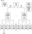
- FIG. 1is a schematic block diagram illustrating one embodiment of a system for wireless power transfer to multiple vehicles
- FIG. 2is a schematic block diagram illustrating one embodiment of a power converter apparatus for wireless power transfer to multiple vehicles
- FIG. 3is a schematic block diagram illustrating one embodiment of a power converter apparatus feeding multiple primary pad apparatuses
- FIG. 4is a schematic block diagram illustrating one embodiment of a resonant converter feeding a primary pad apparatus
- FIG. 5is a schematic block diagram illustrating one embodiment of a resonant converter feeding several primary pad apparatuses through a switching apparatus;
- FIG. 6is a schematic flowchart diagram illustrating one embodiment of a method for wireless power charging.
- FIG. 7is a schematic flowchart diagram illustrating another embodiment of a method for wireless power charging.
- aspects of the present inventionmay be embodied as a system, method, and/or computer program product. Accordingly, aspects of the present invention may take the form of an entirely hardware embodiment, an entirely software embodiment (including firmware, resident software, micro-code, etc.) or an embodiment combining software and hardware aspects that may all generally be referred to herein as a “circuit,” “module,” or “system.” Furthermore, aspects of the present invention may take the form of a computer program product embodied in one or more computer readable medium(s) having program code embodied thereon.
- modulesmay be implemented as a hardware circuit comprising custom VLSI circuits or gate arrays, off-the-shelf semiconductors such as logic chips, transistors, or other discrete components.
- a modulemay also be implemented in programmable hardware devices such as field programmable gate arrays, programmable array logic, programmable logic devices or the like.
- Modulesmay also be implemented in software for execution by various types of processors.
- An identified module of program codemay, for instance, comprise one or more physical or logical blocks of computer instructions which may, for instance, be organized as an object, procedure, or function. Nevertheless, the executables of an identified module need not be physically located together, but may comprise disparate instructions stored in different locations which, when joined logically together, comprise the module and achieve the stated purpose for the module.
- a module of program codemay be a single instruction, or many instructions, and may even be distributed over several different code segments, among different programs, and across several memory devices.
- operational datamay be identified and illustrated herein within modules, and may be embodied in any suitable form and organized within any suitable type of data structure. The operational data may be collected as a single data set, or may be distributed over different locations including over different storage devices, and may exist, at least partially, merely as electronic signals on a system or network.
- the program codemay be stored and/or propagated on in one or more computer readable medium(s).
- the computer program productmay include a computer readable storage medium (or media) having computer readable program instructions thereon for causing a processor to carry out aspects of the present invention.
- the computer readable storage mediumcan be a tangible device that can retain and store instructions for use by an instruction execution device.
- the computer readable storage mediummay be, for example, but is not limited to, an electronic storage device, a magnetic storage device, an optical storage device, an electromagnetic storage device, a semiconductor storage device, or any suitable combination of the foregoing.
- a non-exhaustive list of more specific examples of the computer readable storage mediumincludes the following: a portable computer diskette, a hard disk, a random access memory (“RAM”), a read-only memory (“ROM”), an erasable programmable read-only memory (“EPROM” or Flash memory), a static random access memory (“SRAM”), a portable compact disc read-only memory (“CD-ROM”), a digital versatile disk (“DVD”), a memory stick, a floppy disk, a mechanically encoded device such as punch-cards or raised structures in a groove having instructions recorded thereon, and any suitable combination of the foregoing.
- RAMrandom access memory
- ROMread-only memory
- EPROMerasable programmable read-only memory
- SRAMstatic random access memory
- CD-ROMcompact disc read-only memory
- DVDdigital versatile disk
- memory sticka floppy disk
- mechanically encoded devicesuch as punch-cards or raised structures in a groove having instructions recorded thereon
- a computer readable storage mediumis not to be construed as being transitory signals per se, such as radio waves or other freely propagating electromagnetic waves, electromagnetic waves propagating through a waveguide or other transmission media (e.g., light pulses passing through a fiber-optic cable), or electrical signals transmitted through a wire.
- Computer readable program instructions described hereincan be downloaded to respective computing/processing devices from a computer readable storage medium or to an external computer or external storage device via a network, for example, the Internet, a local area network, a wide area network and/or a wireless network.
- the networkmay comprise copper transmission cables, optical transmission fibers, wireless transmission, routers, firewalls, switches, gateway computers and/or edge servers.
- a network adapter card or network interface in each computing/processing devicereceives computer readable program instructions from the network and forwards the computer readable program instructions for storage in a computer readable storage medium within the respective computing/processing device.
- Computer readable program instructions for carrying out operations of the present inventionmay be assembler instructions, instruction-set-architecture (ISA) instructions, machine instructions, machine dependent instructions, microcode, firmware instructions, state-setting data, or either source code or object code written in any combination of one or more programming languages, including an object oriented programming language such as Smalltalk, C++ or the like, and conventional procedural programming languages, such as the “C” programming language or similar programming languages.
- the computer readable program instructionsmay execute entirely on the user's computer, partly on the user's computer, as a stand-alone software package, partly on the user's computer and partly on a remote computer or entirely on the remote computer or server.
- the remote computermay be connected to the user's computer through any type of network, including a local area network (“LAN”) or a wide area network (“WAN”), or the connection may be made to an external computer (for example, through the Internet using an Internet Service Provider).
- electronic circuitryincluding, for example, programmable logic circuitry, field-programmable gate arrays (“FPGA”), or programmable logic arrays (“PLA”) may execute the computer readable program instructions by utilizing state information of the computer readable program instructions to personalize the electronic circuitry, in order to perform aspects of the present invention.
- These computer readable program instructionsmay be provided to a processor of a general-purpose computer, special purpose computer, or other programmable data processing apparatus to produce a machine, such that the instructions, which execute via the processor of the computer or other programmable data processing apparatus, create means for implementing the functions/acts specified in the flowchart and/or block diagram block or blocks.
- These computer readable program instructionsmay also be stored in a computer readable storage medium that can direct a computer, a programmable data processing apparatus, and/or other devices to function in a particular manner, such that the computer readable storage medium having instructions stored therein comprises an article of manufacture including instructions which implement aspects of the function/act specified in the flowchart and/or block diagram block or blocks.
- the computer readable program instructionsmay also be loaded onto a computer, other programmable data processing apparatus, or other device to cause a series of operational steps to be performed on the computer, other programmable apparatus or other device to produce a computer implemented process, such that the instructions which execute on the computer, other programmable apparatus, or other device implement the functions/acts specified in the flowchart and/or block diagram block or blocks.
- modulesmay be implemented as a hardware circuit comprising custom VLSI circuits or gate arrays, off-the-shelf semiconductors such as logic chips, transistors, or other discrete components.
- a modulemay also be implemented in programmable hardware devices such as field programmable gate arrays, programmable array logic, programmable logic devices or the like.
- Modulesmay also be implemented in software for execution by various types of processors.
- An identified module of program instructionsmay, for instance, comprise one or more physical or logical blocks of computer instructions which may, for instance, be organized as an object, procedure, or function. Nevertheless, the executables of an identified module need not be physically located together, but may comprise disparate instructions stored in different locations which, when joined logically together, comprise the module and achieve the stated purpose for the module.
- each block in the schematic flowchart diagrams and/or schematic block diagramsmay represent a module, segment, or portion of code, which comprises one or more executable instructions of the program code for implementing the specified logical function(s).
- the apparatusincludes a plurality of primary pad apparatuses. Each primary pad apparatus is positioned to transmit power to a secondary pad apparatus of a vehicle.
- the primary transmitter pad apparatusesare spaced apart sufficient for each of a plurality of vehicles to be positioned over one primary pad apparatus of the plurality of primary pad apparatuses.
- the apparatusincludes a power converter apparatus connected to each of the plurality of primary pad apparatuses, a power feed that provides power to the power converter apparatus and a sharing controller that selectively controls which of the plurality of primary pad apparatuses transmits power to a secondary pad apparatus and/or controls power sharing between the primary pad apparatuses.
- the power converter apparatusincludes a direct current (“DC”) bus with a DC voltage, and a plurality of resonant converters, where each of the resonant converters is connected to the DC bus and to a primary pad apparatus.
- the sharing controllercontrols each of the plurality of resonant converters to separately provide power to a connected primary pad apparatus, where the sharing controller selects which of the primary pad apparatuses transmits power.
- the power converter apparatusincludes an alternating current (“AC”) to DC converter that receives power from the power feed and provides power to the DC bus.
- the sharing controlleradjusts the DC voltage of the DC bus and adjusts power output of each of the resonant converters.
- the sharing controlleradjusts the DC voltage of the DC bus to match a total power requirement of vehicles receiving power from the plurality of primary pad apparatuses and the sharing controller adjusts power output of a resonant converter to match a power requirement of a vehicle receiving power from the resonant converter.
- the AC to DC converterincludes a switching power converter that adjusts the DC voltage of the DC bus.
- the AC to DC converterincludes a passive converter.
- each resonant converter of the plurality of resonant convertersincludes an H-bridge and a resonant section and the sharing controller separately controls conduction angle of each resonant converter.
- the apparatusincludes a switching apparatus connected to each primary pad, where the sharing controller selectively connects, through the switching apparatus, each of the primary pads to customize a power delivery capability of each primary pad apparatus.
- the power converter apparatusincludes a plurality of resonant converters and one or more of the primary power pads includes a plurality of primary pads.
- each primary pad apparatus of the plurality of primary pad apparatusesincludes a number of primary pads that is equal to or less than the number of resonant converters in the power converter apparatus and at least one of the primary pad apparatuses comprises two or more primary pads.
- the power converter apparatusincludes an adjustable tuning apparatus that adjusts an amount of capacitance and/or an amount of inductance in a resonant section of the power converter apparatus, where the sharing controller controls the adjustable tuning apparatus to adjust one or more of capacitance and inductance of the power converter apparatus in response to a particular configuration of primary pads.
- the apparatusincludes a power module that adjusts power to each primary pad apparatus to minimize a total power cost over a charging period, where two or more of the plurality of primary pad apparatuses have a vehicle with a secondary pad apparatus positioned to receive power from the corresponding primary pad apparatus.
- the apparatusincludes a plurality of power converter apparatuses, where each power converter apparatus is fed by a separate power feed and each power converter apparatus provides power to a plurality of primary pads. The separate power feeds are within a charging facility, where the power module adjusts power to each primary pad apparatus receiving power from the plurality of resonant converters to minimize power cost for the charging facility.
- a system for multi-pad wireless chargingincludes a plurality of primary pad apparatuses. Each primary pad apparatus is positioned to transmit power to a secondary pad apparatus of a vehicle. The primary transmitter pad apparatuses are spaced apart sufficient for each of a plurality of vehicles to be positioned over one primary pad apparatus of the plurality of primary pads apparatuses.
- the systemincludes a plurality of power converter apparatuses, where each power converter apparatus is connected to two or more primary pad apparatuses of the plurality of primary pad apparatuses.
- the systemincludes a plurality of power feeds. Each power feed provides power to a power converter apparatus of the plurality of power converter apparatuses.
- the systemincludes a sharing controller for each power converter apparatus that selectively controls which of the plurality of primary pad apparatuses transmits power to a secondary pad apparatus and/or controls power sharing between the primary pads.
- the systemincludes a power module that adjusts power to each primary pad apparatus to minimize a total power cost over a charging period. Two or more of the plurality of primary pad apparatuses have a vehicle with a secondary pad apparatus positioned to receive power from the corresponding primary pad apparatus. The total power cost is for a combined amount of power used by power converter apparatuses connected to a metered location.
- the power moduledirects one or more of the sharing controllers to stop providing power to one or more primary pad apparatuses of the plurality of primary pad apparatuses for a period of time while providing power to other primary pad apparatuses of the plurality of primary pad apparatuses during the charging period to minimize the total power cost.
- the systemincludes a charging profile module that communicates with each vehicle with a secondary pad apparatus that is adjacent to a primary pad apparatus to determine battery status information of a battery of each vehicle, where the battery status information includes a battery size, a battery type, a battery configuration, a battery state of charge, and/or a vehicle return to service time.
- adjusting power to each primary pad apparatus to minimize a total power cost over a charging periodincludes determining a total power cost comprising using a peak demand, determining a base power rate, and determining one or more tiered power rates for the charging period.
- two or more of the power feedsare fed by different power sources and one or more of the power sources includes a renewable energy source.
- the power moduleadjusts power to each primary pad to minimize total power costs considering power from the power sources comprising a renewable energy source.
- Another apparatus for multi-pad wireless chargingincludes a plurality of primary pad apparatuses. Each primary pad apparatus is positioned to transmit power to a secondary pad apparatus of a vehicle. The primary transmitter pad apparatuses are spaced apart sufficient for each of a plurality of vehicles to be positioned over one primary pad apparatus of the plurality of primary pad apparatuses.
- the apparatusincludes a power converter apparatus connected to each of the plurality of primary pad apparatuses.
- the power converter apparatusincludes a direct current (“DC”) bus with a DC voltage, an alternating current (“AC”) to DC converter that receives power from the power feed and provides power to the DC bus, and a plurality of resonant converters. Each of the resonant converters is connected to the DC bus and to a primary pad apparatus.
- the apparatusincludes a power feed that provides power to the power converter apparatus, and a sharing controller that selectively controls which of the plurality of primary pad apparatuses transmits power to a secondary pad apparatus and/or controls power sharing between the primary pad apparatuses, where the sharing controller controls each of the plurality of resonant converters to separately provide power to a connected primary pad apparatus, and where the sharing controller selects which of the primary pad apparatuses transmits power.
- FIG. 1is a schematic block diagram illustrating one embodiment of a system 100 for wireless power transfer to multiple vehicles.
- the system 100includes a number of primary pad apparatuses 102 a 1 , 102 a 2 , . . . 102 dn (collectively or generically “ 102 ”), power converter apparatuses 104 a - 104 n (collectively or generically “ 104 ”), power feeds 106 a - 106 n (collectively or generically “ 106 ”), a sharing controller 108 , a utility connection 110 , parking stalls 112 , a power module 114 and a charging profile module 116 , which are described below.
- the system 100includes a plurality of primary pad apparatuses 102 , each positioned to transmit power to a secondary pad apparatus (not shown) of a vehicle (not shown).
- the primary pad apparatuses 102are each spaced apart sufficient for each of a plurality of vehicles to be positioned over one primary pad apparatus (e.g. 102 a 1 ) of the plurality of primary pad apparatuses 102 .
- Each primary pad apparatus 102includes one or more primary pads.
- a primary padis a device for transmitting power wirelessly to a corresponding secondary pad.
- each primary pad apparatus 102includes one primary pad.
- each primary pad apparatus 102includes two or more primary pads.
- a primary pad apparatus 102includes two primary pads located adjacent to each other and fitting within an area sized to fit under a secondary pad apparatus of a vehicle.
- Each primary padis configured to transmit power wirelessly to a secondary pad.
- each primary padmay be connected to a power converter apparatus 104 that generates alternating current (“AC”) power to transmit to the attached primary pad.
- Each primary padmay include one or more coils and may also include one or more magnetic components.
- each primary padis configured to focus an electromagnetic waveform in a direction of where a secondary pad is expected to be located for wireless power transfer.
- a primary padis ground mounted so that a vehicle can drive over the primary pad.
- the primary padmay be flush with the ground surface where vehicles travel and may be configured to support vehicles driving over the primary pad.
- each secondary pad of a secondary pad apparatus of a vehicleis mounted an underside of a vehicle.
- each secondary padis affixed to the vehicle and moves with the vehicle, which creates a gap between the primary pads and the secondary pads of vehicles that drive over the primary pads.
- the gapmay be several inches. In one embodiment, the gap is in the range of 6-14 inches, and may be 10 inches.
- one or more secondary pads of a secondary pad apparatusmove in relation to the vehicle, such as moving down closer to the one or more primary pads of a primary pad apparatus 102 and away from the vehicle to which the secondary pads are attached and/or moving laterally with respect to the vehicle and primary pads.
- the secondary pad apparatus of each vehicleis configured to receive power from the primary pads of a primary pad apparatus 102 and to transfer the received power to a load, such as an electric motor, a battery, electronics, etc. Often, each secondary pad is tuned to a particular frequency of the received power and may have components similar to those of the primary pads of a primary pad apparatus 102 .
- the gap between a primary pad and a secondary pad as well as horizontal alignment of the secondary pad with the primary padcontribute to electromagnetic coupling, which may be expressed in terms of a coupling coefficient.
- efficiency of power transferincreases as the coupling coefficient increases.
- the coupling coefficientis used in determining alignment and a signal may be generated in a primary pad or a secondary pad and detected in the corresponding secondary or primary pad to determine the coupling coefficient between the pads in an effort to determine the coupling coefficient between the primary and secondary pads to determine alignment.
- the system 100includes one or more power converter apparatuses 104 where each power converter apparatus (e.g. 104 a ) is connected to a plurality of primary pad apparatuses (e.g. 102 a 1 - 102 d 1 ). Each power converter apparatus 104 provides power to the connected primary pad apparatuses 102 . In one embodiment, each power converter 104 provides AC power to the connected primary pad apparatuses 102 and may provide AC power at a specific frequency. For example, a power converter apparatus 104 may include one or more resonant converters that generate AC power at a resonant frequency. The resonant converters in combination with elements the primary pads of the primary pad apparatuses 102 may be tuned to a particular resonant frequency.
- the power converter apparatuses 104may include other elements, such as a direct current (“DC”) bus and/or an AC to DC converter, which may be passive or active.
- An active AC to DC converterin one embodiment, includes switching components where a passive converter may include diodes, capacitors, inductors and other passive components.
- the power converter apparatuses 104is a matrix converter or other topology that converts AC power of one frequency to AC power of another frequency.
- the power converter apparatus 104may receive AC power from a utility, renewable energy source or other power source with a fundamental frequency of 60 hertz (“Hz”), 50 Hz, 400 Hz, etc.
- the power converter apparatuses 104may then produce an AC output power signal of a different frequency, such as a resonant frequency or frequency higher or lower than the frequency of the input power.
- the system 100includes a power feed 106 that provides power to the power converter apparatus 104 .
- a single power feed 106provides power to a single power converter apparatus 104 , which feeds a plurality of primary pad apparatuses 102 .
- a single power feed 106 and single power converter apparatus 104may serve several primary pad apparatuses 102 and the system 100 may be configurable to supply different load levels to the primary pad apparatuses 102 .
- a first power converter apparatuse.g. 102 a 1
- the system 100may include four primary pad apparatuses (e.g. 102 a 1 - 102 d 1 ) connected to a first power converter apparatus 104 a .
- the vehiclemay charge at a rate consistent with having four primary pads in the first primary power apparatus 102 a 1 .
- each primary pad apparatus 102 a 1 - 102 d 1may charge at a lower rate than the case of a single vehicle over the first primary pad apparatus 102 a 1 .
- the system 100may provide flexibility for charging vehicles at a lower cost than another system where every primary pad apparatus can provide a maximum amount of power at the same time.
- the system 100includes one or more sharing controllers 108 that selectively control which of the plurality of primary pad apparatuses 102 transmits power to a secondary pad apparatus and/or control power sharing between the primary pads.
- the sharing controller 108may receive information regarding which of the primary pad apparatuses 102 have a vehicle positioned over the primary pads, a state of charge of the battery or batteries of the vehicles, a charging capability of each vehicle, etc. and may selectively control which of the plurality of primary pad apparatuses 102 transmits power to a secondary pad apparatus of a vehicle in position for charging.
- the sharing controller 108may also control power sharing between primary pad apparatuses 102 .
- the sharing controller 108may control power sharing such that one primary pad apparatus (e.g.
- 102 a 1receives half of the power while another primary pad apparatus (e.g. 102 b 1 ) receives one quarter of the power and a third primary pad apparatus (e.g. 102 c 1 ) receives one quarter of the power.
- another primary pad apparatuse.g. 102 b 1
- a third primary pad apparatuse.g. 102 c 1
- the system 100includes a sharing controller 108 for each power converter apparatus 104 .
- the system 100includes one or more sharing controllers 108 where each sharing controller 108 is associated with two or more power converter apparatuses 104 and may include a single sharing controller 108 .
- the sharing controller 108receives information from one or more sensors.
- the sharing controller 108may receive information from an alignment system.
- the sharing controller 108receives information wirelessly from one or more vehicles.
- the sharing controller 108receives information from a central communication facility that gathers vehicle information, such as battery state of charge, vehicle charging capabilities, vehicle secondary pad configurations, etc.
- vehicle informationsuch as battery state of charge, vehicle charging capabilities, vehicle secondary pad configurations, etc.
- One of skill in the artwill recognize other ways that the sharing controller 108 may receive information to control which connected primary pad apparatuses 102 get power as well as power sharing between primary pad apparatuses 102 .
- the system 100includes a utility connection 110 that may be a connection point for the power feeds 106 and may be connected to a power utility, such as a municipal power facility.
- the utility 110is metered by a utility and power cost is based on the metering.
- the meteringmay include kilowatt-hour tracking, peak demand tracking, etc. and the utility that monitors the metering may charge for power based on kilowatt-hours, peak demand, tiered power levels, time-of-day power rates, power factor, etc.
- the utility connection 110may include a transformer, switchgear, an electrical panel, etc. typical of a service entrance. Overcurrent protection and other safety features may be included in the service entrance equipment.
- the system 110depicts parking stalls 112 which represent locations where vehicles park.
- Each parking stall 112may include a primary pad apparatus 102 and may be spaced so that a vehicle may park over each primary pad apparatus 102 .
- the primary pad apparatuses 102are flush to a surface on which the vehicles drive.
- the primary pad apparatuses 102are raised above or recessed below the surface.
- each vehicleincludes a secondary pad apparatus on a side of the vehicle, such as the front of the vehicle, the primary pad apparatuses are oriented vertically at an end of a parking stall 112 .
- a primary pad apparatus 102may be oriented with respect to a parking stall 112 .
- the system 100may include multiple power feeds 106 a - n feeding multiple power converter apparatuses 104 a - n .
- the system 100may be within a charging facility or other location with one meter, or multiple meters contributing to a single power bill or to multiple power bills sent to one entity.
- the entitysuch as an owner, a corporation, etc. may want to minimize utility power costs.
- the system 100includes a power module 114 that adjusts power to each primary pad apparatus 102 to minimize a total power cost over a charging period.
- a charging periodin one embodiment, is a time when two or more vehicles are parked over primary pad apparatuses 102 .
- a charging periodstarts when vehicles return to a facility after the vehicles have completed service for a day until a time when the vehicles leave the facility to return to service.
- the charging periodis a daily, weekly or monthly period over a time where power cost is to be minimized.
- a charging periodmay be a billing cycle.
- a daymay include two or more charging periods where a portion of a fleet of vehicles is at a charging facility during each charging period.
- the power module 114adjusts power to the primary pad apparatuses 102 when two or more of the plurality of primary pad apparatuses 102 have a vehicle with a secondary pad apparatus positioned to receive power from the corresponding primary pad apparatus 102 .
- the total power costis for a combined amount of power used by power converter apparatuses connected to a metered location.
- the total power costmay be for several power converter apparatuses 104 , as depicted in FIG. 1 , for example at the utility connection 110 .
- the system 100includes multiple power sources so that the utility 110 and one or more renewable sources combine to provide power to the one or more power feeds 106 a - n .
- the power module 114adjusts power to each primary pad to minimize total power costs considering power from the power sources comprising a renewable energy source.
- the power module 114may control solar panels to provide power while the utility 110 provides any additional power. The power module 114 may then control power to each primary pad apparatus 102 to keep utility power to be below a power level, to minimize a peak demand, etc.
- the power module 114accounts for power from a wind turbine in combination with utility power.
- One of skill in the artwill recognize other ways for the power module 114 to utilize power from renewable sources while controlling power to each primary pad apparatus 102 to minimize utility power costs.
- the power module 114directs one or more of the sharing controllers 108 to stop providing power to one or more primary pad apparatuses 102 of the plurality of primary pad apparatuses 102 for a period of time while providing power to other primary pad apparatuses 102 of the plurality of primary pad apparatuses during the charging period to minimize the total power cost.
- one or more of the power converter apparatuses 104 a - nare bidirectional so that power stored in a battery of a vehicle over a primary pad apparatus 102 may feed into the system 100 .
- the power module 114may use power from one or more spare vehicles of a fleet to minimize utility power, for example, during a peak energy cost period. The power module 114 may then recharge the battery of each spare vehicle during a lower energy cost period.
- the power module 114may use power from a renewable source to recharge batteries of one or more spare vehicles.
- the power module 114may manage, on a rotational basis, which vehicles are considered spare vehicles and may use excess power from a renewable source to charge batteries of spare vehicles.
- the system 100includes a charging profile module 116 that communicates with each vehicle with a secondary pad apparatus that is adjacent to a primary pad apparatus 102 to determine battery status information of a battery of each vehicle.
- a charging profile module 116may wirelessly link to each vehicle to determine a current battery state of charge for one or more batteries of the vehicle.
- the charging profile module 116connects to a database that includes vehicle charging information, such as battery capacity, secondary pad apparatus capacity, a charging history, etc. of a vehicle.
- the battery status informationincludes a battery size, a battery type, a battery configuration, a battery state of charge, and/or a vehicle return to service time.
- the power module 114may direct the one or more sharing controllers 108 based on the battery status information, a return to service time of a vehicle, etc. to command power sharing between primary pad apparatuses 102 and/or to command charging of some vehicles while delaying charging of other vehicles.
- FIG. 2is a schematic block diagram illustrating one embodiment 200 of a power converter apparatus 104 for wireless power transfer to multiple vehicles.
- the power converter apparatus 104includes resonant converters (e.g. 202 a - 202 d , collectively or generically “ 202 ”), an AC to DC converter 204 , and a DC bus 206 , which are described below.
- FIG. 2is merely one possible power converter apparatus 104 and other power converter apparatuses are possible, as discussed above in relation to the system 100 of FIG. 1 .
- the power converter apparatus 104includes two or more resonant converters 202 .
- the power converter apparatus 104may include four resonant converters 202 a - d as depicted in FIG. 2 , but other power converters 104 may include more or less resonant converters 202 .
- each resonant converteris connected to the DC bus 206 , which receives power from the AC to DC converter 204 .
- the DC bus 206in one embodiment, includes one or more capacitors (not shown), which may be part of a low pass filter or may be used to maintain a DC voltage on the DC bus 206 during transients. The capacitors may also be used for a hold up time to provide power for a period of time when the AC to DC converter 204 is not providing power.
- the one or more capacitorsare part of the AC to DC converter 204 .
- the resonant converters 202convert DC power to AC power suitable for transmission to the primary pad apparatuses 102 .
- each resonant converter 202may produce an AC output voltage with a frequency corresponding to a resonant frequency of the resonant converter 202 and the connected primary pad apparatus 102 .
- Having multiple resonant converters 202 a - dprovides several advantages.
- each resonant converter 202may feed a separate primary pad apparatus 102 .
- each resonant converter 202may have smaller components than a single larger resonant converter. For instance, where a power output is 250 kilowatts (“kW”), each resonant converter 202 may be sized at 62.5 kW.
- having multiple resonant converters 202provides redundancy so that if one resonant converter (e.g. 202 a ) fails, the remaining resonant converters 202 b - d may continue to provide power.
- the power converter apparatus 104includes an AC to DC converter 204 that receives AC power and produces DC power for the DC bus 206 .
- the AC to DC converter 204in one embodiment, is an active converter.
- the AC to DC converter 204may be a switching power converter that includes switching elements and regulates the output DC voltage.
- An active AC to DC converter 204may also include passive elements, such as a rectifier, low pass filter, etc. that convert the input AC power to an intermediate DC voltage and a DC to DC converter then converts the intermediate DC voltage to a regulated DC voltage of the DC bus 206 .
- the AC to DC converter 204includes power factor correction and harmonic reduction.
- the AC to DC converter 204may maintain a power factor at the input to the AC to DC converter 204 above a particular level, such as 90%.
- the AC to DC converter 204may also reduce harmonics caused by switching within the AC to DC converter 204 and/or the resonant converters 202 .
- the AC to DC converter 204is passive and does not include active switching components.
- the AC to DC converter 204may include a half-bridge or a full-bridge rectifier and may also include filtering components, such as inductors and capacitors.
- the DC voltage 206 on the DC bus 206may vary based on power demand from the resonant converters 202 .
- the AC to DC converter 204adjusts the DC voltage of the DC bus 206 to control power output of the power converter apparatus 104 .
- the resonant converters 202may run open loop and may maintain a constant conduction angle, constant duty cycle, etc. so that as DC voltage on the DC bus 206 rises power output to the primary pad apparatuses 102 increases.
- the AC to DC converter 204maintains the DC voltage at the DC bus 206 at a constant value and each resonant converter 202 varies switching (i.e. conduction angle, duty cycle, etc.) to vary power output.
- the AC to DC converter 204varies the DC voltage of the DC bus 206 and the resonant converters 202 vary switching to control power sharing between the resonant converters 202 . Raising the DC voltage of the DC bus 206 may increase power capability while varying switching in the resonant converters 202 may then vary power sharing between the resonant converters 202 .
- the sharing controller 108may determine an overall power need and may control the AC to DC converter 204 and may command the resonant converters 202 for power sharing.
- the sharing controller 108controls which resonant converter 202 provides power. In another embodiment, switching of a particular resonant converter (e.g. 202 a ) may be halted to stop the resonant converter 202 a from producing power. The sharing controller 108 may send a signal to a resonant converter 202 to stop switching.
- a particular resonant convertere.g. 202 a
- the sharing controller 108may send a signal to a resonant converter 202 to stop switching.
- each resonant converter(e.g. 202 a ) includes a feedback loop for controlling the output of the resonant converter 202 a .
- the resonant converters 202may be current fed converters that control output current by adjusting a conduction angle of the resonant converters 202 .
- the resonant converters 202are inductor-capacitor-inductor (“LCL”) load resonant converters. Other embodiments may include other resonant converter topologies.
- FIG. 3is a schematic block diagram illustrating one embodiment 300 of a power converter apparatus 104 feeding multiple primary pad apparatuses 102 .
- the power converter apparatus 104 depicted in FIG. 3is substantially similar to the power converter apparatus 104 of FIG. 2 .
- Each primary pad apparatus 102includes one or more primary pads (collectively or generically “ 302 ”).
- a first primary pad apparatus 102 a and a second primary pad apparatus 102 beach includes four primary pads 302 a 1 - 302 d 1 , 302 a 2 - 302 d 2 .
- a third primary pad apparatus 102 cincludes two primary pads 302 a 3 , 302 b 3 and a fourth primary pad apparatus 102 d includes a single primary pad 302 a 4 .
- the varying number of primary pads 102illustrates that a charging facility may include different types of primary pad apparatuses 102 .
- the primary pads 302 of the primary pad apparatuses 102may vary in shape, configuration, power capability,
- a switching apparatus 304connects the resonant converters 202 to the various primary pads 302 .
- the switching apparatus 304is a matrix switcher with a capability of connecting each resonant converter 202 to each primary pad 302 .
- the switchesmay be mechanical contactors, semiconductor switches, relays, etc. or a combination thereof and may be controlled by the sharing controller 108 connected to the power converter apparatus 104 .
- the switching apparatus 304may include less switches to limit the number of possible connections.
- the switching apparatus 304allows for reconfiguration of resonant converters 202 based on the needs of the various vehicles receiving energy from the primary pads 302 .
- the first and second primary pad apparatuses 102 a , 102 bmay be used for vehicles with four secondary pads for full power charging while the third and fourth primary pad apparatuses 102 c , 102 d may be configured for smaller vehicles or may be used for a vehicle with a higher charging capacity for charging at a rate lower than a maximum charging capability of the vehicle.
- the power module 114directs vehicles to a parking stall 112 appropriate for the charging needs of the various vehicles.
- FIG. 4is a schematic block diagram illustrating one embodiment 400 of a resonant converter 202 feeding a primary pad apparatus 102 a .
- the resonant converter 202is substantially similar to the resonant converter 202 described above in relation to the power converter apparatuses 104 of FIGS. 2 and 3 .
- the resonant converter 202is an LCL load resonant converter and includes a switching module 402 and a tuning section 404 .
- the switching module 402includes a positive connection connected to the DC bus 206 and a negative connection that is connected to ground or another reference point.
- the switching module 402is a typical H-bridge switching section with four switches S 1 , S 2 , S 3 and S 4 . Typically, when switches S 1 and S 3 are closed, the voltage across the tuning section 404 has a first polarity and when switches S 2 and S 4 are closed, the voltage across the tuning section 404 has an opposite polarity.
- Timing of switchingis generally controlled to maximize efficiency and to control power output.
- the switching module 402is controlled by adjusting conduction angle.
- conduction angleis an amount of time when the switches are off in relation to a switching period. Often, the conduction angle varies from 0-180 degrees. As conduction angle increases, power output decreases. At a conduction angle of zero degrees, switches S 1 and S 3 turn off at the same time that switches S 2 and S 4 turn on, and vice versa. At a conduction angle of 180 degrees, the switches all remain off Adjustment of timing of each switch individually may also be used to achieve zero voltage switching or other higher efficiency condition. The output of the switching section approximates a sinusoidal AC output.
- the switches S 1 -S 4may be semiconductor switches, such as insulated gate bi-polar transistors (“IGBT”), metal-oxide semiconductor field effect transistors (“MOSFET”), thyristors, and the like.
- the switching module 402may include other components, such as diodes, snubbers, control circuitry, etc.
- the tuning section 404includes series inductors L 1 a , L 1 b .
- the series inductors L 1 a and L 1 bmay be combined to form a single series inductor L 1 .
- the tuning section 404includes a parallel capacitor C 1 and optionally a series capacitor C 2 . Some embodiments may include multiple parallel capacitors C 1 . Some embodiments may not include the series capacitor C 2 . In other embodiments, the series capacitor C 2 is split so there is a series capacitor C 2 in each leg, like the series inductors L 1 a , L 1 b . Other components may also be included, such as coupled inductors that help to ensure equal sharing, etc.
- the primary pad apparatus 102 aincludes a primary pad with a charging coil, represented by an inductance Lp, and may optionally include a series capacitor C 3 .
- the series capacitoris either in the tuning section 404 or in a primary pad 102 , but not both.
- the designincludes a series capacitor C 2 in the tuning section 404 and in the primary pad C 3 .
- the resonant converter 202does not include a series capacitor C 3 .
- One of skill in the artwill recognize other topologies for a resonant converter 202 and other components for an LCL load resonant converter.
- FIG. 5is a schematic block diagram illustrating one embodiment 500 of a resonant converter 202 feeding several primary pad apparatuses 202 through a switching apparatus 304 .
- the resonant converter 202is substantially similar to the resonant converter 202 of FIG. 4 except that the tuning apparatus 404 is replaced with an adjustable tuning apparatus 502 where each of the elements can be changed.
- the series inductors L 1 a and L 1 bare now labeled L 1 a 1 and L 1 b 1 .
- Additional inductors L 1 a 2 , L 1 a 3 , L 1 a 4 , L 1 b 2 , L 1 b 3 , L 1 b 4can be placed in parallel with the series inductors L 1 a 1 , L 1 b 1 to decrease the overall series inductance.
- parallel capacitancecan be changed by adding capacitors C 1 b , C 1 c and/or C 1 d in parallel with the parallel capacitor C 1 a .
- Series capacitancecan be increased by switching in parallel capacitors C 2 b , C 2 c and/or C 2 d with the series capacitor C 2 a .
- Series capacitance in the primary pad apparatuses 102can also be affected in a similar way.
- the switching apparatus 304can be used to connect primary pads (e.g. 302 ) and/or primary pad apparatuses 102 in parallel, which will affect the resonant frequency.
- changing inductance and capacitance of the adjustable tuning section 502 and/or primary pad apparatuses 102may be used to compensate for the parallel primary pads 302 to maintain the resonant frequency at a particular value or within a particular range.
- Feedback loopsmay also be adjusted to compensate for parallel primary pads 302 .
- one primary pade.g. 302 a 1
- additional feedback loopsmay be used to more closely control current sharing between parallel primary pads 302 .
- the adjustable tuning section 502 and tuning section 404are depicted in the power converter apparatuses 104 of FIGS. 4 and 5
- the adjustable tuning section 502 and tuning section 404may also be located with the primary pads 302 and/or primary pad apparatuses 102 .
- FIG. 6is a schematic flowchart diagram illustrating one embodiment of a method 600 for wireless power charging.
- the method 600begins and wirelessly senses 602 vehicles positioned for charging and senses 604 charging requirements for each vehicle positioned for charging.
- the method 600determines 606 a return to service time for each vehicle positioned for charging and calculates 608 a charging schedule that minimizes power cost over a charging period.
- the method 600starts 610 charging based on the charging schedule while staggering and/or varying charging of the vehicles positioned for charging, and the method 600 ends.
- the method 600is implemented in the power module 114 .
- Calculating 608 a charging schedule that minimizes power costmay take into account peak demand, a state of charge of each vehicle, power rates, and the like. For example, if a particular charging period is 10 hours and four vehicles are positioned for charging and each vehicle takes two hours to charge, the power module 114 may charge one vehicle at a time or may slow charging of the four vehicles to each be fully charged in 2.5 hours.
- FIG. 7is a schematic flowchart diagram illustrating another embodiment of a method 700 for wireless power charging.
- the method 700begins and senses 702 that a vehicle is aligned with a primary pad apparatus 102 and establishes 704 wireless communication with the vehicle.
- the method 700senses 706 charging requirements for the vehicle and determines 708 a return to service time for the vehicle.
- the power module 114may communicate wirelessly with each vehicle to determine a battery state of charge, battery health, etc.
- the power module 114may also determine an identifier for the vehicle and may consult a database to determine the charging capabilities of the vehicle, a service schedule, etc.
- the power module 114communicates with the vehicle before aligning 702 with a primary pad apparatus 102 to direct the vehicle to a particular primary pad 302 with appropriate charging resources.
- the method 700calculates a charging schedule for the vehicles aligned with a primary pad apparatus 102 .
- the power module 114determines a schedule for when vehicles are expected to arrive for charging and calculates a preliminary charging schedule and then adjusts the charging schedule based on vehicles that are actually aligned with primary pad apparatuses 102 .
- the method 700starts 712 charging of selected vehicles (some or all of the vehicles aligned with a primary pad apparatus 102 ) based on the charging schedule and determines 714 if charging is complete for a vehicle. If the method 700 determines that charging is complete for a vehicle 714 , the method 700 returns and recalculates 710 a charging schedule and then starts 712 charging vehicles based on the charging schedule.
- the method 700determines 716 if the time has reached a return to service for a vehicle. Ideally, the vehicle would be fully charged before the time for return to service. If the method 700 determines that the time has reached a return to service time for a vehicle, the method 700 returns recalculates 710 the charging schedule with the returned to service vehicle not included. If the method 700 determines 716 that the time has not reached a return to service time for a vehicle, the method 700 determines 718 if there is a new vehicle aligned with a primary pad apparatus 102 .
- the method 700determines 718 that there is not a new vehicle aligned with a primary pad apparatus 102 , the method 700 again returns to recalculate 710 a charging schedule.
- recalculating 710 the charging schedulemay include determining a status or progress of charging on the charging schedule without recalculating a charging schedule. Other conditions may signal recalculating the charging schedule, such as early termination of charging, charging taking longer than planned, a power outage, etc. If the method 700 determines that there is a new vehicle aligned with a primary pad apparatus 102 , the method 700 returns and senses 702 , alignment of the vehicle, establishes 704 wireless communication with the vehicle, etc.
Landscapes
- Engineering & Computer Science (AREA)
- Power Engineering (AREA)
- Transportation (AREA)
- Mechanical Engineering (AREA)
- Computer Networks & Wireless Communication (AREA)
- Charge And Discharge Circuits For Batteries Or The Like (AREA)
Abstract
Description
Claims (20)
Priority Applications (2)
| Application Number | Priority Date | Filing Date | Title |
|---|---|---|---|
| US16/900,755US11296557B2 (en) | 2017-05-30 | 2020-06-12 | Single feed multi-pad wireless charging |
| US17/713,150US11621586B2 (en) | 2017-05-30 | 2022-04-04 | Single feed multi-pad wireless charging |
Applications Claiming Priority (3)
| Application Number | Priority Date | Filing Date | Title |
|---|---|---|---|
| US201762512699P | 2017-05-30 | 2017-05-30 | |
| US15/993,387US10686336B2 (en) | 2017-05-30 | 2018-05-30 | Single feed multi-pad wireless charging |
| US16/900,755US11296557B2 (en) | 2017-05-30 | 2020-06-12 | Single feed multi-pad wireless charging |
Related Parent Applications (1)
| Application Number | Title | Priority Date | Filing Date |
|---|---|---|---|
| US15/993,387ContinuationUS10686336B2 (en) | 2017-05-30 | 2018-05-30 | Single feed multi-pad wireless charging |
Related Child Applications (1)
| Application Number | Title | Priority Date | Filing Date |
|---|---|---|---|
| US17/713,150ContinuationUS11621586B2 (en) | 2017-05-30 | 2022-04-04 | Single feed multi-pad wireless charging |
Publications (2)
| Publication Number | Publication Date |
|---|---|
| US20200313463A1 US20200313463A1 (en) | 2020-10-01 |
| US11296557B2true US11296557B2 (en) | 2022-04-05 |
Family
ID=64456180
Family Applications (3)
| Application Number | Title | Priority Date | Filing Date |
|---|---|---|---|
| US15/993,387Active2038-07-25US10686336B2 (en) | 2017-05-30 | 2018-05-30 | Single feed multi-pad wireless charging |
| US16/900,755ActiveUS11296557B2 (en) | 2017-05-30 | 2020-06-12 | Single feed multi-pad wireless charging |
| US17/713,150ActiveUS11621586B2 (en) | 2017-05-30 | 2022-04-04 | Single feed multi-pad wireless charging |
Family Applications Before (1)
| Application Number | Title | Priority Date | Filing Date |
|---|---|---|---|
| US15/993,387Active2038-07-25US10686336B2 (en) | 2017-05-30 | 2018-05-30 | Single feed multi-pad wireless charging |
Family Applications After (1)
| Application Number | Title | Priority Date | Filing Date |
|---|---|---|---|
| US17/713,150ActiveUS11621586B2 (en) | 2017-05-30 | 2022-04-04 | Single feed multi-pad wireless charging |
Country Status (4)
| Country | Link |
|---|---|
| US (3) | US10686336B2 (en) |
| EP (1) | EP3631946A4 (en) |
| CN (1) | CN110999029A (en) |
| WO (1) | WO2018222758A1 (en) |
Cited By (2)
| Publication number | Priority date | Publication date | Assignee | Title |
|---|---|---|---|---|
| US20210296934A1 (en)* | 2017-06-29 | 2021-09-23 | Witricity Corporation | Protection and control of wireless power systems |
| US20220231542A1 (en)* | 2017-05-30 | 2022-07-21 | Wireless Advanced Vehicle Electrification, Llc | Single feed multi-pad wireless charging |
Families Citing this family (12)
| Publication number | Priority date | Publication date | Assignee | Title |
|---|---|---|---|---|
| US11059380B2 (en)* | 2017-09-21 | 2021-07-13 | Utah State University | Dynamic inductive wireless power transmitter system with a power transmitter module |
| CN111742464A (en) | 2017-12-22 | 2020-10-02 | 无线先进车辆电气化有限公司 | Wireless Power Transfer Pad with Multiple Windings |
| US11462943B2 (en) | 2018-01-30 | 2022-10-04 | Wireless Advanced Vehicle Electrification, Llc | DC link charging of capacitor in a wireless power transfer pad |
| US11437854B2 (en) | 2018-02-12 | 2022-09-06 | Wireless Advanced Vehicle Electrification, Llc | Variable wireless power transfer system |
| KR102667984B1 (en)* | 2019-02-19 | 2024-05-23 | 삼성전자 주식회사 | Wireless charging transmitter and method for adjusting the received power of wireless charging receiver |
| CN110816321B (en) | 2019-08-12 | 2022-11-11 | 华为技术有限公司 | Wireless charging transmitting device, transmitting method and wireless charging system |
| IT202000011944A1 (en)* | 2020-05-21 | 2021-11-21 | Free2Move Esolutions S P A | ELECTRIC VEHICLE CHARGING SYSTEM |
| CN111884357B (en)* | 2020-08-12 | 2021-12-21 | 西南交通大学 | An Efficiency Optimization Method for Wireless Power Transfer System Based on Switchable LCL Circuit |
| US11817722B2 (en)* | 2021-03-11 | 2023-11-14 | Inductev Inc. | Opportunity charging of queued electric vehicles |
| US12145461B2 (en) | 2022-01-06 | 2024-11-19 | Ev Charging Solutions, Llc | Inductive charging station |
| US20230302948A1 (en)* | 2022-03-23 | 2023-09-28 | Wireless Advanced Vehicle Electrification, Llc | Optimizing energy availability in an energy distribution network |
| WO2024246238A1 (en)* | 2023-05-30 | 2024-12-05 | Capactech Limited | An electric vehicle park having a management system |
Citations (194)
| Publication number | Priority date | Publication date | Assignee | Title |
|---|---|---|---|---|
| US3938018A (en) | 1974-09-16 | 1976-02-10 | Dahl Ernest A | Induction charging system |
| US3942535A (en) | 1973-09-27 | 1976-03-09 | G. D. Searle & Co. | Rechargeable tissue stimulating system |
| US4527123A (en) | 1980-07-08 | 1985-07-02 | Sentronic Of California Incorporated | Improved method and apparatus for detecting and locating residually magnetized items |
| US4800328A (en) | 1986-07-18 | 1989-01-24 | Inductran Inc. | Inductive power coupling with constant voltage output |
| US4836344A (en) | 1987-05-08 | 1989-06-06 | Inductran Corporation | Roadway power and control system for inductively coupled transportation system |
| WO1989010651A1 (en) | 1988-04-28 | 1989-11-02 | Every-Sys Ag | Electric transmission device |
| US5207304A (en) | 1991-12-03 | 1993-05-04 | The Regents Of The University Of California | Inductive energization system and method for vehicles |
| WO1993023909A1 (en) | 1992-05-10 | 1993-11-25 | Auckland Uniservices Limited | A primary inductive pathway |
| US5293308A (en) | 1991-03-26 | 1994-03-08 | Auckland Uniservices Limited | Inductive power distribution system |
| EP0409880B1 (en) | 1988-04-11 | 1994-12-14 | The University Of Western Australia | Actuator and communication system |
| WO1995011545A1 (en) | 1993-10-21 | 1995-04-27 | Auckland Uniservices Limited | Inductive power pick-up coils |
| US5469036A (en) | 1993-03-29 | 1995-11-21 | Eto Denki Co. | Apparatus for feeding electricity to motor driving means of a movable body |
| US5617003A (en) | 1995-03-24 | 1997-04-01 | Kabushiki Kaisha Toyoda Jidoshokki Seisakusho | Method and apparatus for charging a battery of an electric vehicle |
| NZ274939A (en) | 1993-10-21 | 1997-06-24 | Auckland Uniservices Ltd | Inductive power pick-up coils best aligned activated by controller |
| US5654621A (en) | 1992-10-28 | 1997-08-05 | Daimler-Benz Aktiengesellschaft | Method and arrangement for automatic contactless charging |
| US5669470A (en) | 1994-05-05 | 1997-09-23 | H. R. Ross Industries, Inc. | Roadway-powered electric vehicle system |
| US5701121A (en) | 1988-04-11 | 1997-12-23 | Uniscan Ltd. | Transducer and interrogator device |
| US5703461A (en) | 1995-06-28 | 1997-12-30 | Kabushiki Kaisha Toyoda Jidoshokki Seisakusho | Inductive coupler for electric vehicle charger |
| US5710502A (en) | 1992-09-02 | 1998-01-20 | Cableco And Poumey | System for recharging the storage batteries of an electric motor vehicle |
| US5734355A (en) | 1994-04-12 | 1998-03-31 | Daiichi Denpa Kogyo Kabushiki Kaisha | Coupling device for coaxial cable and antenna apparatus |
| WO1998031073A2 (en) | 1997-01-13 | 1998-07-16 | Advanced Metal Technologies Ltd. | Electrical coupler device |
| US5808373A (en) | 1996-03-11 | 1998-09-15 | Harness System Technologies Research | Vehicle glove box adapted to receive and power electrical equipment |
| JPH10261898A (en) | 1997-03-21 | 1998-09-29 | Matsushita Electric Ind Co Ltd | Work positioning method |
| US5831841A (en) | 1996-08-02 | 1998-11-03 | Diafuku Co., Ltd. | Contactless power distribution system |
| US5842986A (en) | 1995-08-16 | 1998-12-01 | Proton Sciences Corp. | Ferromagnetic foreign body screening method and apparatus |
| US5850135A (en) | 1996-01-30 | 1998-12-15 | Sumitomo Wiring Systems, Ltd. | Connecting system and a connection method |
| WO1998057413A1 (en) | 1997-06-12 | 1998-12-17 | Auckland Uniservices Limited | Wireless signals in inductive power transfer systems |
| US5909100A (en) | 1996-08-09 | 1999-06-01 | Sumitomo Wiring Systems, Ltd. | Charging connector for electric vehicle |
| JPH11186086A (en) | 1997-12-17 | 1999-07-09 | Tokin Corp | Manufacture of spiral coil for noncontact power transmitter |
| US5945888A (en) | 1997-06-09 | 1999-08-31 | Northrop Grumman Corporation | Dielectric resonator tunable via a change in gas pressure |
| US5991170A (en) | 1998-02-03 | 1999-11-23 | Sony Corporation | Equipment and method for transmitting electric power |
| US6011320A (en) | 1997-03-25 | 2000-01-04 | Yazaki Corporation | Vehicle anti-theft device using both electromagnetic induction and frequency modulation transmission of power and data |
| US6075433A (en) | 1995-05-29 | 2000-06-13 | Matsushita Electric Industrial Co., Ltd. | Power supply unit |
| US6188179B1 (en) | 1995-10-24 | 2001-02-13 | Auckland Uniservices Limited | Induction circuits for lighting |
| JP2001044054A (en) | 1999-07-29 | 2001-02-16 | Dainippon Printing Co Ltd | Signal and power transmission device, rotary joint and signal transmission board |
| US20010012208A1 (en) | 1997-05-06 | 2001-08-09 | Auckland Uniservices Limited | Inductive power distribution system |
| US6305467B1 (en) | 1998-09-01 | 2001-10-23 | Halliburton Energy Services, Inc. | Wireless coiled tubing joint locator |
| US6350951B1 (en) | 1997-12-29 | 2002-02-26 | Intel Corporation | Electric shielding of on-board devices |
| JP2002078103A (en) | 2000-08-23 | 2002-03-15 | Tsubakimoto Chain Co | Non-contact power feeder pickup, carrier and carrier system |
| JP2002137659A (en) | 2000-08-23 | 2002-05-14 | Shinko Electric Co Ltd | Non-contact feeder |
| US6421600B1 (en) | 1994-05-05 | 2002-07-16 | H. R. Ross Industries, Inc. | Roadway-powered electric vehicle system having automatic guidance and demand-based dispatch features |
| JP2002246248A (en) | 2001-02-14 | 2002-08-30 | Fdk Corp | Non-contact coupler |
| US6459218B2 (en) | 1994-07-13 | 2002-10-01 | Auckland Uniservices Limited | Inductively powered lamp unit |
| JP2002299138A (en) | 2001-04-02 | 2002-10-11 | Kawasaki Steel Corp | Flat magnetic element for contactless charger |
| US6483202B1 (en) | 1997-11-17 | 2002-11-19 | Auckland Uniservices Limited | Control of inductive power transfer pickups |
| US20020177884A1 (en) | 2001-05-23 | 2002-11-28 | Ahn Tae Young | Apparatus for contactless power transfer for implantable medical device |
| US6501364B1 (en) | 2001-06-15 | 2002-12-31 | City University Of Hong Kong | Planar printed-circuit-board transformers with effective electromagnetic interference (EMI) shielding |
| US6541966B1 (en) | 1998-06-27 | 2003-04-01 | Qinetiq Limited | Precision metal locating apparatus |
| JP3432317B2 (en) | 1994-11-18 | 2003-08-04 | エヌイーシートーキン株式会社 | Cordless power station |
| US20030210106A1 (en) | 2002-05-13 | 2003-11-13 | Splashpower Limited, A Company Incorporated In The Uk | Contact-less power transfer |
| WO2003096512A2 (en) | 2002-05-13 | 2003-11-20 | Splashpower Limited | Contact-less power transfer |
| GB2389720A (en) | 2002-06-10 | 2003-12-17 | Univ City Hong Kong | Planar inductive battery charger |
| WO2003105308A1 (en) | 2002-01-11 | 2003-12-18 | City University Of Hong Kong | Planar inductive battery charger |
| US20040119576A1 (en) | 2001-02-14 | 2004-06-24 | Fumiaki Nakao | Noncontact coupler |
| WO2005024865A2 (en) | 2003-09-08 | 2005-03-17 | Splashpower Limited | Inductive power transfer units having flux shields |
| JP2005073313A (en) | 2003-08-26 | 2005-03-17 | Asahi Glass Co Ltd | Electric vehicle power supply system, electric vehicle used in the system, and power supply device |
| US20050083019A1 (en) | 2002-04-06 | 2005-04-21 | Wampfler Aktiengesellschaft | Device for the inductive transfer of electrical energy |
| US20050161300A1 (en) | 2002-06-12 | 2005-07-28 | Wampfler Aktiengesellschaft | Primary conductor arrangement for a system for the inductive transmission of electrical energy |
| US6960968B2 (en) | 2002-06-26 | 2005-11-01 | Koninklijke Philips Electronics N.V. | Planar resonator for wireless power transfer |
| DE102004023197A1 (en) | 2004-05-11 | 2005-12-15 | Siemens Ag | Apparatus for charging a rechargeable electric energy source of a remote control key for a vehicle allowing recharging only when authorized |
| WO2006001557A1 (en) | 2004-06-25 | 2006-01-05 | Hanrim Postech Co., Ltd. | Wireless charging pad and battery pack using radio frequency identification technology |
| US20060006873A1 (en) | 2003-09-16 | 2006-01-12 | Nelson Carl V | Switched coil receiver antenna for metal detector |
| JP2006042519A (en) | 2004-07-28 | 2006-02-09 | Seiko Epson Corp | Contactless power transmission device |
| US7019620B2 (en) | 2001-07-04 | 2006-03-28 | Wampfler Aktiengesellschaft | Device for the inductive transmission of electrical power |
| US7116540B2 (en) | 2002-06-06 | 2006-10-03 | Wampfler Aktiengesellschaft | Device for inductively transmitting electrical energy |
| US7157913B2 (en) | 2003-10-01 | 2007-01-02 | The Johns Hopkins University | Re-configurable induction coil for metal detection |
| US20070072474A1 (en) | 2005-04-27 | 2007-03-29 | Nigel Beasley | Flexible power adapter systems and methods |
| US20070131505A1 (en) | 2005-07-16 | 2007-06-14 | Kim Bryan H J | Magnetic Induction Charging System for Vehicles |
| US7243752B2 (en) | 2002-04-12 | 2007-07-17 | Wampfler Aktiengesellschaft | Device for inductively supplying power and guiding a mobile object |
| US20070188284A1 (en) | 2003-02-26 | 2007-08-16 | Dobbs John M | Shielded power coupling device |
| US20080061733A1 (en) | 2006-08-11 | 2008-03-13 | Shoichi Toya | Battery charger |
| JP2008087733A (en) | 2006-10-05 | 2008-04-17 | Showa Aircraft Ind Co Ltd | Noncontact power supply device |
| US7375492B2 (en) | 2003-12-12 | 2008-05-20 | Microsoft Corporation | Inductively charged battery pack |
| US7375493B2 (en) | 2003-12-12 | 2008-05-20 | Microsoft Corporation | Inductive battery charger |
| US7378817B2 (en) | 2003-12-12 | 2008-05-27 | Microsoft Corporation | Inductive power adapter |
| WO2008118178A1 (en) | 2007-03-27 | 2008-10-02 | Massachusetts Institute Of Technology | Wireless energy transfer |
| US7451839B2 (en) | 2005-05-24 | 2008-11-18 | Rearden, Llc | System and method for powering a vehicle using radio frequency generators |
| US20090010028A1 (en) | 2005-08-16 | 2009-01-08 | Access Business Group International Llc | Inductive power supply, remote device powered by inductive power supply and method for operating same |
| WO2009023155A2 (en) | 2007-08-09 | 2009-02-19 | Nigelpower, Llc | Increasing the q factor of a resonator |
| US20090058189A1 (en) | 2007-08-13 | 2009-03-05 | Nigelpower, Llc | Long range low frequency resonator and materials |
| US20090096413A1 (en)* | 2006-01-31 | 2009-04-16 | Mojo Mobility, Inc. | System and method for inductive charging of portable devices |
| US7521890B2 (en) | 2005-12-27 | 2009-04-21 | Power Science Inc. | System and method for selective transfer of radio frequency power |
| WO2009050625A2 (en) | 2007-10-15 | 2009-04-23 | Nxp B.V. | Power transfer system |
| WO2009081126A1 (en) | 2007-12-21 | 2009-07-02 | Amway (Europe) Limited | Circuitry for inductive power transfer |
| EP2091129A2 (en) | 2008-02-18 | 2009-08-19 | Lunatone Industrielle Elektronik GmbH | Energy supply module |
| JP2009205050A (en) | 2008-02-29 | 2009-09-10 | Seiko Epson Corp | Projection system and projector |
| US7605496B2 (en) | 2004-05-11 | 2009-10-20 | Access Business Group International Llc | Controlling inductive power transfer systems |
| US7620438B2 (en) | 2006-03-31 | 2009-11-17 | Abbott Diabetes Care Inc. | Method and system for powering an electronic device |
| US20090313174A1 (en) | 2008-06-16 | 2009-12-17 | International Business Machines Corporation | Approving Energy Transaction Plans Associated with Electric Vehicles |
| US20090313032A1 (en) | 2008-06-16 | 2009-12-17 | International Business Machines Corporation | Maintaining Energy Principal Preferences for a Vehicle by a Remote Preferences Service |
| US20090313034A1 (en) | 2008-06-16 | 2009-12-17 | International Business Machines Corporation | Generating Dynamic Energy Transaction Plans |
| US20100007307A1 (en)* | 2008-07-09 | 2010-01-14 | Access Business Group International Llc | Wireless charging system |
| US20100017249A1 (en) | 2008-07-11 | 2010-01-21 | Fincham Carson C K | Systems and methods for electric vehicle charging and power management |
| NZ555128A (en) | 2007-05-10 | 2010-01-29 | Auckland Uniservices Ltd | Inductive power transfer pad and system |
| US20100110741A1 (en) | 2008-10-31 | 2010-05-06 | University Of Florida Research Foundation, Inc. | Miniature high voltage/current ac switch using low voltage single supply control |
| US7741734B2 (en) | 2005-07-12 | 2010-06-22 | Massachusetts Institute Of Technology | Wireless non-radiative energy transfer |
| US7791312B2 (en) | 2006-10-24 | 2010-09-07 | Hanrim Postech Co., Ltd. | Non-contact charger available of wireless data and power transmission, charging battery-pack and mobile device using non-contact charger |
| US7804272B2 (en) | 2006-11-10 | 2010-09-28 | Mitsubishi Heavy Industries, Ltd. | Non-contact type power feeder system for mobile object and protecting apparatus thereof |
| US20100259217A1 (en) | 2009-04-08 | 2010-10-14 | Access Business Group International Llc | Selectable coil array |
| US20100259109A1 (en) | 2009-04-14 | 2010-10-14 | Sony Corporation | Power transmission device, power transmission method, power reception device, power reception method, and power transmission system |
| US7825543B2 (en) | 2005-07-12 | 2010-11-02 | Massachusetts Institute Of Technology | Wireless energy transfer |
| US7825537B2 (en) | 2008-11-14 | 2010-11-02 | Harris Corporation | Inductive power transfer system and method |
| US20100276995A1 (en) | 2009-04-29 | 2010-11-04 | Thomas Louis Marzetta | Security for wireless transfer of electrical power |
| US20100277121A1 (en) | 2008-09-27 | 2010-11-04 | Hall Katherine L | Wireless energy transfer between a source and a vehicle |
| US20100315080A1 (en) | 2006-10-24 | 2010-12-16 | Andrew Duncan | metal detector |
| US20100328044A1 (en) | 2006-10-26 | 2010-12-30 | Koninklijke Philips Electronics N.V. | Inductive power system and method of operation |
| US20110031967A1 (en) | 2008-03-05 | 2011-02-10 | National University Corporation Toyohashi Unversity of Technology | Nondestructive inspection apparatus using squid magnetic sensor |
| US7893564B2 (en) | 2008-08-05 | 2011-02-22 | Broadcom Corporation | Phased array wireless resonant power delivery system |
| US7909483B2 (en) | 2006-07-21 | 2011-03-22 | Koninklijke Philips Electronics N.V. | Lighting system |
| US20110074346A1 (en) | 2009-09-25 | 2011-03-31 | Hall Katherine L | Vehicle charger safety system and method |
| US7952322B2 (en) | 2006-01-31 | 2011-05-31 | Mojo Mobility, Inc. | Inductive power source and charging system |
| US20110184842A1 (en) | 2010-01-28 | 2011-07-28 | Roger D Melen | Energy transfer systems and methods for mobile vehicles |
| US8008888B2 (en) | 2007-10-25 | 2011-08-30 | Toyota Jidosha Kabushiki Kaisha | Electrical powered vehicle and power feeding device for vehicle |
| US8040103B2 (en) | 2005-08-19 | 2011-10-18 | City University Of Hong Kong | Battery charging apparatus with planar inductive charging platform |
| US8050068B2 (en) | 2003-05-23 | 2011-11-01 | Auckland Uniservices Limited | Variable reactive element in a resonant converter circuit |
| US8069100B2 (en) | 2009-01-06 | 2011-11-29 | Access Business Group International Llc | Metered delivery of wireless power |
| US8085556B2 (en) | 2007-04-20 | 2011-12-27 | Intersil Americas Inc. | Dynamic converter topology |
| US8111042B2 (en) | 2008-08-05 | 2012-02-07 | Broadcom Corporation | Integrated wireless resonant power charging and communication channel |
| US8125208B2 (en) | 2004-04-30 | 2012-02-28 | Geir Olav Gyland | Transformer device utilizing an air gap for non-contact energy transmission from the primary side to the secondary side |
| US20120098330A1 (en) | 2009-07-02 | 2012-04-26 | Toyota Jidosha Kabushiki Kaisha | Coil unit, noncontact power receiving apparatus, noncontact power transmitting apparatus, noncontact power feeding system, and vehicle |
| US8183938B2 (en) | 2005-04-29 | 2012-05-22 | Auckland Uniservices Limited | Tuning methods and apparatus for inductively coupled power transfer (ICPT) systems |
| US8217621B2 (en) | 2010-02-12 | 2012-07-10 | Fu Da Tong Technology Co., Ltd. | Frequency modulation type wireless power supply and charger system |
| US20120181875A1 (en) | 2009-07-14 | 2012-07-19 | Conductix-Wampfler Ag, | Device for inductive transmission of electrical energy |
| US20120187757A1 (en) | 2009-07-14 | 2012-07-26 | Conductix-Wampfler Ag | Device for inductive transmission of electrical energy |
| US8232764B2 (en) | 2006-03-24 | 2012-07-31 | Kabushiki Kaisha Toshiba | Power receiving device, and electronic apparatus and non-contact charging system using the same |
| US8269595B2 (en) | 2007-07-11 | 2012-09-18 | Seiko Epson Corporation | Coil unit and electronic instrument |
| US8271089B2 (en) | 2009-04-03 | 2012-09-18 | Medtronic, Inc. | Hybrid rectification for recharging an implantable medical device |
| US8278784B2 (en) | 2008-07-28 | 2012-10-02 | Qualcomm Incorporated | Wireless power transmission for electronic devices |
| US8290531B2 (en) | 2008-04-28 | 2012-10-16 | Sony Corporation | Power transmitting apparatus, power transmission method, program, and power transmission system |
| US8304935B2 (en) | 2008-09-27 | 2012-11-06 | Witricity Corporation | Wireless energy transfer using field shaping to reduce loss |
| US8332547B2 (en) | 2008-04-04 | 2012-12-11 | Sony Corporation | Power exchange device, power exchange method, program, and power exchange system |
| US8339096B2 (en) | 2006-11-20 | 2012-12-25 | Semiconductor Energy Laboratory Co., Ltd. | Wireless power receiving device |
| US8362651B2 (en) | 2008-10-01 | 2013-01-29 | Massachusetts Institute Of Technology | Efficient near-field wireless energy transfer using adiabatic system variations |
| US20130033118A1 (en) | 2011-08-04 | 2013-02-07 | Witricity Corporation | Tunable wireless power architectures |
| US8378523B2 (en) | 2007-03-02 | 2013-02-19 | Qualcomm Incorporated | Transmitters and receivers for wireless energy transfer |
| US8390249B2 (en) | 2009-11-30 | 2013-03-05 | Broadcom Corporation | Battery with integrated wireless power receiver and/or RFID |
| US8405486B2 (en) | 2008-12-16 | 2013-03-26 | Hitachi, Ltd. | Electric power transmitting and receiving device, electric power transmitting device and electric power receiving device |
| US8432070B2 (en) | 2008-08-25 | 2013-04-30 | Qualcomm Incorporated | Passive receivers for wireless power transmission |
| US8446045B2 (en) | 2008-08-20 | 2013-05-21 | Intel Corporation | Flat, asymmetric, and E-field confined wireless power transfer apparatus and method thereof |
| US8446046B2 (en) | 2008-10-03 | 2013-05-21 | Access Business Group International Llc | Power system |
| US8466654B2 (en) | 2008-07-08 | 2013-06-18 | Qualcomm Incorporated | Wireless high power transfer under regulatory constraints |
| US8471410B2 (en) | 2008-09-27 | 2013-06-25 | Witricity Corporation | Wireless energy transfer over distance using field shaping to improve the coupling factor |
| US8469122B2 (en) | 2005-05-24 | 2013-06-25 | Rearden, Llc | System and method for powering vehicle using radio frequency signals and feedback |
| US20130187561A1 (en) | 2010-09-29 | 2013-07-25 | Felix Franck | Circuit Arrangement for Operating at Least Two Semiconductor Light Sources |
| US8498763B2 (en) | 2008-06-16 | 2013-07-30 | International Business Machines Corporation | Maintaining energy principal preferences in a vehicle |
| US20130214591A1 (en) | 2012-02-14 | 2013-08-22 | Ut-Battelle, Llc | Wireless power charging using point of load controlled high frequency power converters |
| US8531162B2 (en) | 2008-06-16 | 2013-09-10 | International Business Machines Corporation | Network based energy preference service for managing electric vehicle charging preferences |
| US8536739B2 (en) | 2009-06-25 | 2013-09-17 | Murata Manufacturing Co., Ltd. | Power transfer system and noncontact charging device |
| US8547057B2 (en) | 2009-11-17 | 2013-10-01 | Qualcomm Incorporated | Systems and methods for selective wireless power transfer |
| JP5324901B2 (en) | 2008-12-09 | 2013-10-23 | 日立コンシューマエレクトロニクス株式会社 | Non-contact power transmission system |
| US8581437B2 (en) | 2006-12-20 | 2013-11-12 | Analogic Corporation | Non-contact rotary power transfer system |
| US8587154B2 (en) | 2007-08-28 | 2013-11-19 | Access Business Group International Llc | Inductive power supply |
| US8639191B2 (en) | 2003-10-31 | 2014-01-28 | Auckland Uniservices Limited | Communication apparatus and method |
| WO2014018504A2 (en) | 2012-07-23 | 2014-01-30 | Cornell University | System and methods for large scale charging of electric vehicles |
| US8643219B2 (en) | 2008-05-22 | 2014-02-04 | Mitsubishi Electric Corporation | Electronic equipment and method for connecting electronic circuit substrate |
| US8674551B2 (en) | 2008-06-06 | 2014-03-18 | University Of Florida Research Foundation, Inc. | Method and apparatus for contactless power transfer |
| US8710701B2 (en) | 2008-02-27 | 2014-04-29 | Qualcomm Incorporated | Antennas and their coupling characteristics for wireless power transfer via magnetic coupling |
| US8723366B2 (en) | 2008-09-27 | 2014-05-13 | Witricity Corporation | Wireless energy transfer resonator enclosures |
| US8749334B2 (en) | 2007-05-10 | 2014-06-10 | Auckland Uniservices Ltd. | Multi power sourced electric vehicle |
| US8766482B2 (en) | 2007-09-17 | 2014-07-01 | Qualcomm Incorporated | High efficiency and power transfer in wireless power magnetic resonators |
| US8810071B2 (en) | 2008-04-03 | 2014-08-19 | Koninklijke Philips N.V. | Wireless power transmission system |
| US8833533B2 (en) | 2009-04-06 | 2014-09-16 | Korea Advanced Institute Of Science And Technology | Ultra slim power supply device and power acquisition device for electric vehicle |
| US8855554B2 (en) | 2008-03-05 | 2014-10-07 | Qualcomm Incorporated | Packaging and details of a wireless power device |
| US8855786B2 (en) | 2009-03-09 | 2014-10-07 | Nucurrent, Inc. | System and method for wireless power transfer in implantable medical devices |
| US8878393B2 (en) | 2008-05-13 | 2014-11-04 | Qualcomm Incorporated | Wireless power transfer for vehicles |
| US8884581B2 (en) | 2010-05-19 | 2014-11-11 | Qualcomm Incorporated | Adaptive wireless energy transfer system |
| US8901857B2 (en) | 2008-05-23 | 2014-12-02 | Osram Gesellschaft Mit Beschraenkter Haftung | Wireless supplyable lighting module |
| US8907617B2 (en) | 2009-06-25 | 2014-12-09 | Murata Manufacturing Co., Ltd | Power transfer system and noncontact charging device |
| US8914080B2 (en) | 2009-02-04 | 2014-12-16 | Intel Mobile Communications GmbH | Determining device, method for determining of transmitting parameter, energy transmitting device and method for wirelessly transmitting energy |
| US8912687B2 (en) | 2008-09-27 | 2014-12-16 | Witricity Corporation | Secure wireless energy transfer for vehicle applications |
| US8937409B2 (en) | 2009-06-25 | 2015-01-20 | Murata Manufacturing Co., Ltd. | Power transfer system and noncontact charging device |
| US20150091517A1 (en) | 2013-09-27 | 2015-04-02 | Siemens Aktiengesellschaft | Charging station, method, and electrically powered vehicle for the wireless energy-transfer coupling of an electrically powered vehicle |
| US20150094887A1 (en)* | 2013-09-27 | 2015-04-02 | Qualcomm Incorporated | Device alignment in inductive power transfer systems |
| US9065284B2 (en) | 2004-09-16 | 2015-06-23 | Auckland Uniservices Limited | Inductively powered mobile sensor system |
| US9105959B2 (en) | 2008-09-27 | 2015-08-11 | Witricity Corporation | Resonator enclosure |
| US9178376B2 (en) | 2008-12-12 | 2015-11-03 | Hanrim Postech Co., Ltd. | Non-contact charging station with power transmission planar spiral core, non-contact power-receiving apparatus, and method for controlling the same |
| US9184595B2 (en) | 2008-09-27 | 2015-11-10 | Witricity Corporation | Wireless energy transfer in lossy environments |
| US9190875B2 (en) | 2008-05-13 | 2015-11-17 | Qualcomm Incorporated | Method and apparatus with negative resistance in wireless power transfers |
| US20160025821A1 (en) | 2014-07-25 | 2016-01-28 | Qualcomm Incorporated | Guidance and alignment system and methods for electric vehicle wireless charging systems |
| US9312924B2 (en) | 2009-02-10 | 2016-04-12 | Qualcomm Incorporated | Systems and methods relating to multi-dimensional wireless charging |
| WO2016076735A1 (en) | 2014-11-13 | 2016-05-19 | Powerbyproxi Limited | System for charging electronic devices |
| US9415149B2 (en)* | 2012-05-21 | 2016-08-16 | Yale University | Method and system for powering implantable devices |
| US9442172B2 (en) | 2011-09-09 | 2016-09-13 | Witricity Corporation | Foreign object detection in wireless energy transfer systems |
| US9450456B2 (en) | 2008-04-21 | 2016-09-20 | Qualcomm Incorporated | System and method for efficient wireless power transfer to devices located on and outside a charging base |
| US9461505B2 (en) | 2009-12-03 | 2016-10-04 | Mitsubishi Electric Research Laboratories, Inc. | Wireless energy transfer with negative index material |
| US9561730B2 (en) | 2010-04-08 | 2017-02-07 | Qualcomm Incorporated | Wireless power transmission in electric vehicles |
| US9634730B2 (en) | 2007-07-09 | 2017-04-25 | Qualcomm Incorporated | Wireless energy transfer using coupled antennas |
| WO2017118432A1 (en) | 2016-01-07 | 2017-07-13 | 中兴通讯股份有限公司 | Direct-current multi-input and single-output resonant converter and control method therefor |
| US9751416B2 (en) | 2008-06-16 | 2017-09-05 | International Business Machines Corporation | Generating energy transaction plans |
| US9767955B2 (en) | 2008-05-09 | 2017-09-19 | Auckland Uniservices Limited | Multi power sourced electric vehicle |
| US9774086B2 (en) | 2007-03-02 | 2017-09-26 | Qualcomm Incorporated | Wireless power apparatus and methods |
| US9905351B2 (en) | 2012-03-28 | 2018-02-27 | Panasonic Intellectual Property Management Co., Ltd. | Power supply apparatus |
| US10658847B2 (en)* | 2015-08-07 | 2020-05-19 | Nucurrent, Inc. | Method of providing a single structure multi mode antenna for wireless power transmission using magnetic field coupling |
| EP3666804B1 (en) | 2018-12-14 | 2023-04-05 | Borealis AG | Polypropylene composition with favourable combination of optics, softness and low sealing |
Family Cites Families (8)
| Publication number | Priority date | Publication date | Assignee | Title |
|---|---|---|---|---|
| US3008888A (en) | 1957-07-04 | 1961-11-14 | Fujimoto Shigenobu | Method for the production of processed papers |
| US3040103A (en) | 1959-07-24 | 1962-06-19 | Roussel Uclaf | Process for the preparation of alkyl borines |
| US3069100A (en) | 1959-12-14 | 1962-12-18 | Donald A Schuler | Fire fighting apparatus |
| US3050068A (en) | 1961-08-16 | 1962-08-21 | Remigio E Primus | Insertable cigar holder |
| DE4236340C2 (en) | 1992-10-28 | 1994-11-10 | Daimler Benz Ag | Arrangement for the inductive transmission of energy |
| CN104025418B (en)* | 2011-12-27 | 2017-03-15 | 三菱电机株式会社 | Ems |
| US9789779B2 (en)* | 2014-08-25 | 2017-10-17 | Toyota Jidosha Kabushiki Kaisha | Regional charging control service |
| US10686336B2 (en)* | 2017-05-30 | 2020-06-16 | Wireless Advanced Vehicle Electrification, Inc. | Single feed multi-pad wireless charging |
- 2018
- 2018-05-30USUS15/993,387patent/US10686336B2/enactiveActive
- 2018-05-30EPEP18809682.0Apatent/EP3631946A4/enactivePending
- 2018-05-30WOPCT/US2018/035197patent/WO2018222758A1/ennot_activeCeased
- 2018-05-30CNCN201880049926.6Apatent/CN110999029A/enactivePending
- 2020
- 2020-06-12USUS16/900,755patent/US11296557B2/enactiveActive
- 2022
- 2022-04-04USUS17/713,150patent/US11621586B2/enactiveActive
Patent Citations (208)
| Publication number | Priority date | Publication date | Assignee | Title |
|---|---|---|---|---|
| US3942535A (en) | 1973-09-27 | 1976-03-09 | G. D. Searle & Co. | Rechargeable tissue stimulating system |
| US3938018A (en) | 1974-09-16 | 1976-02-10 | Dahl Ernest A | Induction charging system |
| US4527123A (en) | 1980-07-08 | 1985-07-02 | Sentronic Of California Incorporated | Improved method and apparatus for detecting and locating residually magnetized items |
| US4800328A (en) | 1986-07-18 | 1989-01-24 | Inductran Inc. | Inductive power coupling with constant voltage output |
| US4836344A (en) | 1987-05-08 | 1989-06-06 | Inductran Corporation | Roadway power and control system for inductively coupled transportation system |
| EP0409880B1 (en) | 1988-04-11 | 1994-12-14 | The University Of Western Australia | Actuator and communication system |
| US5701121A (en) | 1988-04-11 | 1997-12-23 | Uniscan Ltd. | Transducer and interrogator device |
| WO1989010651A1 (en) | 1988-04-28 | 1989-11-02 | Every-Sys Ag | Electric transmission device |
| US5293308A (en) | 1991-03-26 | 1994-03-08 | Auckland Uniservices Limited | Inductive power distribution system |
| US5207304A (en) | 1991-12-03 | 1993-05-04 | The Regents Of The University Of California | Inductive energization system and method for vehicles |
| WO1993023909A1 (en) | 1992-05-10 | 1993-11-25 | Auckland Uniservices Limited | A primary inductive pathway |
| US5710502A (en) | 1992-09-02 | 1998-01-20 | Cableco And Poumey | System for recharging the storage batteries of an electric motor vehicle |
| US5654621A (en) | 1992-10-28 | 1997-08-05 | Daimler-Benz Aktiengesellschaft | Method and arrangement for automatic contactless charging |
| US5469036A (en) | 1993-03-29 | 1995-11-21 | Eto Denki Co. | Apparatus for feeding electricity to motor driving means of a movable body |
| WO1995011545A1 (en) | 1993-10-21 | 1995-04-27 | Auckland Uniservices Limited | Inductive power pick-up coils |
| US5528113A (en) | 1993-10-21 | 1996-06-18 | Boys; John T. | Inductive power pick-up coils |
| NZ274939A (en) | 1993-10-21 | 1997-06-24 | Auckland Uniservices Ltd | Inductive power pick-up coils best aligned activated by controller |
| US5821638A (en) | 1993-10-21 | 1998-10-13 | Auckland Uniservices Limited | Flux concentrator for an inductive power transfer system |
| US5734355A (en) | 1994-04-12 | 1998-03-31 | Daiichi Denpa Kogyo Kabushiki Kaisha | Coupling device for coaxial cable and antenna apparatus |
| US6421600B1 (en) | 1994-05-05 | 2002-07-16 | H. R. Ross Industries, Inc. | Roadway-powered electric vehicle system having automatic guidance and demand-based dispatch features |
| US5669470A (en) | 1994-05-05 | 1997-09-23 | H. R. Ross Industries, Inc. | Roadway-powered electric vehicle system |
| US6459218B2 (en) | 1994-07-13 | 2002-10-01 | Auckland Uniservices Limited | Inductively powered lamp unit |
| JP3432317B2 (en) | 1994-11-18 | 2003-08-04 | エヌイーシートーキン株式会社 | Cordless power station |
| US5617003A (en) | 1995-03-24 | 1997-04-01 | Kabushiki Kaisha Toyoda Jidoshokki Seisakusho | Method and apparatus for charging a battery of an electric vehicle |
| US6075433A (en) | 1995-05-29 | 2000-06-13 | Matsushita Electric Industrial Co., Ltd. | Power supply unit |
| US5703461A (en) | 1995-06-28 | 1997-12-30 | Kabushiki Kaisha Toyoda Jidoshokki Seisakusho | Inductive coupler for electric vehicle charger |
| US5842986A (en) | 1995-08-16 | 1998-12-01 | Proton Sciences Corp. | Ferromagnetic foreign body screening method and apparatus |
| US6188179B1 (en) | 1995-10-24 | 2001-02-13 | Auckland Uniservices Limited | Induction circuits for lighting |
| US5850135A (en) | 1996-01-30 | 1998-12-15 | Sumitomo Wiring Systems, Ltd. | Connecting system and a connection method |
| US5808373A (en) | 1996-03-11 | 1998-09-15 | Harness System Technologies Research | Vehicle glove box adapted to receive and power electrical equipment |
| US5831841A (en) | 1996-08-02 | 1998-11-03 | Diafuku Co., Ltd. | Contactless power distribution system |
| US5909100A (en) | 1996-08-09 | 1999-06-01 | Sumitomo Wiring Systems, Ltd. | Charging connector for electric vehicle |
| WO1998031073A2 (en) | 1997-01-13 | 1998-07-16 | Advanced Metal Technologies Ltd. | Electrical coupler device |
| JPH10261898A (en) | 1997-03-21 | 1998-09-29 | Matsushita Electric Ind Co Ltd | Work positioning method |
| US6011320A (en) | 1997-03-25 | 2000-01-04 | Yazaki Corporation | Vehicle anti-theft device using both electromagnetic induction and frequency modulation transmission of power and data |
| US20010012208A1 (en) | 1997-05-06 | 2001-08-09 | Auckland Uniservices Limited | Inductive power distribution system |
| US6317338B1 (en) | 1997-05-06 | 2001-11-13 | Auckland Uniservices Limited | Power supply for an electroluminescent display |
| US5945888A (en) | 1997-06-09 | 1999-08-31 | Northrop Grumman Corporation | Dielectric resonator tunable via a change in gas pressure |
| WO1998057413A1 (en) | 1997-06-12 | 1998-12-17 | Auckland Uniservices Limited | Wireless signals in inductive power transfer systems |
| US6483202B1 (en) | 1997-11-17 | 2002-11-19 | Auckland Uniservices Limited | Control of inductive power transfer pickups |
| JPH11186086A (en) | 1997-12-17 | 1999-07-09 | Tokin Corp | Manufacture of spiral coil for noncontact power transmitter |
| US6350951B1 (en) | 1997-12-29 | 2002-02-26 | Intel Corporation | Electric shielding of on-board devices |
| US5991170A (en) | 1998-02-03 | 1999-11-23 | Sony Corporation | Equipment and method for transmitting electric power |
| US6541966B1 (en) | 1998-06-27 | 2003-04-01 | Qinetiq Limited | Precision metal locating apparatus |
| US6305467B1 (en) | 1998-09-01 | 2001-10-23 | Halliburton Energy Services, Inc. | Wireless coiled tubing joint locator |
| JP2001044054A (en) | 1999-07-29 | 2001-02-16 | Dainippon Printing Co Ltd | Signal and power transmission device, rotary joint and signal transmission board |
| JP2002137659A (en) | 2000-08-23 | 2002-05-14 | Shinko Electric Co Ltd | Non-contact feeder |
| JP2002078103A (en) | 2000-08-23 | 2002-03-15 | Tsubakimoto Chain Co | Non-contact power feeder pickup, carrier and carrier system |
| JP2002246248A (en) | 2001-02-14 | 2002-08-30 | Fdk Corp | Non-contact coupler |
| US20040119576A1 (en) | 2001-02-14 | 2004-06-24 | Fumiaki Nakao | Noncontact coupler |
| JP2002299138A (en) | 2001-04-02 | 2002-10-11 | Kawasaki Steel Corp | Flat magnetic element for contactless charger |
| US20020177884A1 (en) | 2001-05-23 | 2002-11-28 | Ahn Tae Young | Apparatus for contactless power transfer for implantable medical device |
| US6501364B1 (en) | 2001-06-15 | 2002-12-31 | City University Of Hong Kong | Planar printed-circuit-board transformers with effective electromagnetic interference (EMI) shielding |
| US7019620B2 (en) | 2001-07-04 | 2006-03-28 | Wampfler Aktiengesellschaft | Device for the inductive transmission of electrical power |
| WO2003105308A1 (en) | 2002-01-11 | 2003-12-18 | City University Of Hong Kong | Planar inductive battery charger |
| US20050083019A1 (en) | 2002-04-06 | 2005-04-21 | Wampfler Aktiengesellschaft | Device for the inductive transfer of electrical energy |
| US7243752B2 (en) | 2002-04-12 | 2007-07-17 | Wampfler Aktiengesellschaft | Device for inductively supplying power and guiding a mobile object |
| WO2003096512A2 (en) | 2002-05-13 | 2003-11-20 | Splashpower Limited | Contact-less power transfer |
| US20030210106A1 (en) | 2002-05-13 | 2003-11-13 | Splashpower Limited, A Company Incorporated In The Uk | Contact-less power transfer |
| US7116540B2 (en) | 2002-06-06 | 2006-10-03 | Wampfler Aktiengesellschaft | Device for inductively transmitting electrical energy |
| GB2389720A (en) | 2002-06-10 | 2003-12-17 | Univ City Hong Kong | Planar inductive battery charger |
| US7576514B2 (en) | 2002-06-10 | 2009-08-18 | Cityu Research Limited | Planar inductive battery charging system |
| US20050189910A1 (en) | 2002-06-10 | 2005-09-01 | Hui Shu-Yuen R. | Planar inductive battery charger |
| US7164255B2 (en) | 2002-06-10 | 2007-01-16 | City University Of Hong Kong | Inductive battery charger system with primary transformer windings formed in a multi-layer structure |
| US20050161300A1 (en) | 2002-06-12 | 2005-07-28 | Wampfler Aktiengesellschaft | Primary conductor arrangement for a system for the inductive transmission of electrical energy |
| US6960968B2 (en) | 2002-06-26 | 2005-11-01 | Koninklijke Philips Electronics N.V. | Planar resonator for wireless power transfer |
| US20070188284A1 (en) | 2003-02-26 | 2007-08-16 | Dobbs John M | Shielded power coupling device |
| US8050068B2 (en) | 2003-05-23 | 2011-11-01 | Auckland Uniservices Limited | Variable reactive element in a resonant converter circuit |
| JP2005073313A (en) | 2003-08-26 | 2005-03-17 | Asahi Glass Co Ltd | Electric vehicle power supply system, electric vehicle used in the system, and power supply device |
| WO2005024865A2 (en) | 2003-09-08 | 2005-03-17 | Splashpower Limited | Inductive power transfer units having flux shields |
| US20070064406A1 (en) | 2003-09-08 | 2007-03-22 | Beart Pilgrim G W | Inductive power transfer units having flux shields |
| US20060006873A1 (en) | 2003-09-16 | 2006-01-12 | Nelson Carl V | Switched coil receiver antenna for metal detector |
| US7157913B2 (en) | 2003-10-01 | 2007-01-02 | The Johns Hopkins University | Re-configurable induction coil for metal detection |
| US8639191B2 (en) | 2003-10-31 | 2014-01-28 | Auckland Uniservices Limited | Communication apparatus and method |
| US7375492B2 (en) | 2003-12-12 | 2008-05-20 | Microsoft Corporation | Inductively charged battery pack |
| US7375493B2 (en) | 2003-12-12 | 2008-05-20 | Microsoft Corporation | Inductive battery charger |
| US7378817B2 (en) | 2003-12-12 | 2008-05-27 | Microsoft Corporation | Inductive power adapter |
| US8125208B2 (en) | 2004-04-30 | 2012-02-28 | Geir Olav Gyland | Transformer device utilizing an air gap for non-contact energy transmission from the primary side to the secondary side |
| US7605496B2 (en) | 2004-05-11 | 2009-10-20 | Access Business Group International Llc | Controlling inductive power transfer systems |
| DE102004023197A1 (en) | 2004-05-11 | 2005-12-15 | Siemens Ag | Apparatus for charging a rechargeable electric energy source of a remote control key for a vehicle allowing recharging only when authorized |
| WO2006001557A1 (en) | 2004-06-25 | 2006-01-05 | Hanrim Postech Co., Ltd. | Wireless charging pad and battery pack using radio frequency identification technology |
| JP2006042519A (en) | 2004-07-28 | 2006-02-09 | Seiko Epson Corp | Contactless power transmission device |
| US9065284B2 (en) | 2004-09-16 | 2015-06-23 | Auckland Uniservices Limited | Inductively powered mobile sensor system |
| US20070072474A1 (en) | 2005-04-27 | 2007-03-29 | Nigel Beasley | Flexible power adapter systems and methods |
| US8183938B2 (en) | 2005-04-29 | 2012-05-22 | Auckland Uniservices Limited | Tuning methods and apparatus for inductively coupled power transfer (ICPT) systems |
| US7451839B2 (en) | 2005-05-24 | 2008-11-18 | Rearden, Llc | System and method for powering a vehicle using radio frequency generators |
| US8469122B2 (en) | 2005-05-24 | 2013-06-25 | Rearden, Llc | System and method for powering vehicle using radio frequency signals and feedback |
| US9444265B2 (en) | 2005-07-12 | 2016-09-13 | Massachusetts Institute Of Technology | Wireless energy transfer |
| US7741734B2 (en) | 2005-07-12 | 2010-06-22 | Massachusetts Institute Of Technology | Wireless non-radiative energy transfer |
| US7825543B2 (en) | 2005-07-12 | 2010-11-02 | Massachusetts Institute Of Technology | Wireless energy transfer |
| US20070131505A1 (en) | 2005-07-16 | 2007-06-14 | Kim Bryan H J | Magnetic Induction Charging System for Vehicles |
| US20090010028A1 (en) | 2005-08-16 | 2009-01-08 | Access Business Group International Llc | Inductive power supply, remote device powered by inductive power supply and method for operating same |
| US8040103B2 (en) | 2005-08-19 | 2011-10-18 | City University Of Hong Kong | Battery charging apparatus with planar inductive charging platform |
| US7521890B2 (en) | 2005-12-27 | 2009-04-21 | Power Science Inc. | System and method for selective transfer of radio frequency power |
| US8169185B2 (en) | 2006-01-31 | 2012-05-01 | Mojo Mobility, Inc. | System and method for inductive charging of portable devices |
| US7952322B2 (en) | 2006-01-31 | 2011-05-31 | Mojo Mobility, Inc. | Inductive power source and charging system |
| US20090096413A1 (en)* | 2006-01-31 | 2009-04-16 | Mojo Mobility, Inc. | System and method for inductive charging of portable devices |
| US8232764B2 (en) | 2006-03-24 | 2012-07-31 | Kabushiki Kaisha Toshiba | Power receiving device, and electronic apparatus and non-contact charging system using the same |
| US7620438B2 (en) | 2006-03-31 | 2009-11-17 | Abbott Diabetes Care Inc. | Method and system for powering an electronic device |
| US7909483B2 (en) | 2006-07-21 | 2011-03-22 | Koninklijke Philips Electronics N.V. | Lighting system |
| US20080061733A1 (en) | 2006-08-11 | 2008-03-13 | Shoichi Toya | Battery charger |
| JP2008087733A (en) | 2006-10-05 | 2008-04-17 | Showa Aircraft Ind Co Ltd | Noncontact power supply device |
| US7791312B2 (en) | 2006-10-24 | 2010-09-07 | Hanrim Postech Co., Ltd. | Non-contact charger available of wireless data and power transmission, charging battery-pack and mobile device using non-contact charger |
| US20100315080A1 (en) | 2006-10-24 | 2010-12-16 | Andrew Duncan | metal detector |
| US20100328044A1 (en) | 2006-10-26 | 2010-12-30 | Koninklijke Philips Electronics N.V. | Inductive power system and method of operation |
| US7804272B2 (en) | 2006-11-10 | 2010-09-28 | Mitsubishi Heavy Industries, Ltd. | Non-contact type power feeder system for mobile object and protecting apparatus thereof |
| US8339096B2 (en) | 2006-11-20 | 2012-12-25 | Semiconductor Energy Laboratory Co., Ltd. | Wireless power receiving device |
| US8581437B2 (en) | 2006-12-20 | 2013-11-12 | Analogic Corporation | Non-contact rotary power transfer system |
| US9774086B2 (en) | 2007-03-02 | 2017-09-26 | Qualcomm Incorporated | Wireless power apparatus and methods |
| US8378523B2 (en) | 2007-03-02 | 2013-02-19 | Qualcomm Incorporated | Transmitters and receivers for wireless energy transfer |
| US8482157B2 (en) | 2007-03-02 | 2013-07-09 | Qualcomm Incorporated | Increasing the Q factor of a resonator |
| WO2008118178A1 (en) | 2007-03-27 | 2008-10-02 | Massachusetts Institute Of Technology | Wireless energy transfer |
| EP2130287A1 (en) | 2007-03-27 | 2009-12-09 | Massachusetts Institute of Technology | Wireless energy transfer |
| US8085556B2 (en) | 2007-04-20 | 2011-12-27 | Intersil Americas Inc. | Dynamic converter topology |
| NZ555128A (en) | 2007-05-10 | 2010-01-29 | Auckland Uniservices Ltd | Inductive power transfer pad and system |
| US8749334B2 (en) | 2007-05-10 | 2014-06-10 | Auckland Uniservices Ltd. | Multi power sourced electric vehicle |
| US9634730B2 (en) | 2007-07-09 | 2017-04-25 | Qualcomm Incorporated | Wireless energy transfer using coupled antennas |
| US8269595B2 (en) | 2007-07-11 | 2012-09-18 | Seiko Epson Corporation | Coil unit and electronic instrument |
| WO2009023155A2 (en) | 2007-08-09 | 2009-02-19 | Nigelpower, Llc | Increasing the q factor of a resonator |
| US20090058189A1 (en) | 2007-08-13 | 2009-03-05 | Nigelpower, Llc | Long range low frequency resonator and materials |
| US8587154B2 (en) | 2007-08-28 | 2013-11-19 | Access Business Group International Llc | Inductive power supply |
| US8766482B2 (en) | 2007-09-17 | 2014-07-01 | Qualcomm Incorporated | High efficiency and power transfer in wireless power magnetic resonators |
| WO2009050625A2 (en) | 2007-10-15 | 2009-04-23 | Nxp B.V. | Power transfer system |
| US8008888B2 (en) | 2007-10-25 | 2011-08-30 | Toyota Jidosha Kabushiki Kaisha | Electrical powered vehicle and power feeding device for vehicle |
| US8884468B2 (en) | 2007-12-21 | 2014-11-11 | Access Business Group International Llc | Circuitry for inductive power transfer |
| WO2009081126A1 (en) | 2007-12-21 | 2009-07-02 | Amway (Europe) Limited | Circuitry for inductive power transfer |
| EP2091129A2 (en) | 2008-02-18 | 2009-08-19 | Lunatone Industrielle Elektronik GmbH | Energy supply module |
| US8710701B2 (en) | 2008-02-27 | 2014-04-29 | Qualcomm Incorporated | Antennas and their coupling characteristics for wireless power transfer via magnetic coupling |
| JP2009205050A (en) | 2008-02-29 | 2009-09-10 | Seiko Epson Corp | Projection system and projector |
| US8855554B2 (en) | 2008-03-05 | 2014-10-07 | Qualcomm Incorporated | Packaging and details of a wireless power device |
| US20110031967A1 (en) | 2008-03-05 | 2011-02-10 | National University Corporation Toyohashi Unversity of Technology | Nondestructive inspection apparatus using squid magnetic sensor |
| US8810071B2 (en) | 2008-04-03 | 2014-08-19 | Koninklijke Philips N.V. | Wireless power transmission system |
| US8332547B2 (en) | 2008-04-04 | 2012-12-11 | Sony Corporation | Power exchange device, power exchange method, program, and power exchange system |
| US9450456B2 (en) | 2008-04-21 | 2016-09-20 | Qualcomm Incorporated | System and method for efficient wireless power transfer to devices located on and outside a charging base |
| US8290531B2 (en) | 2008-04-28 | 2012-10-16 | Sony Corporation | Power transmitting apparatus, power transmission method, program, and power transmission system |
| US9767955B2 (en) | 2008-05-09 | 2017-09-19 | Auckland Uniservices Limited | Multi power sourced electric vehicle |
| US9190875B2 (en) | 2008-05-13 | 2015-11-17 | Qualcomm Incorporated | Method and apparatus with negative resistance in wireless power transfers |
| US8878393B2 (en) | 2008-05-13 | 2014-11-04 | Qualcomm Incorporated | Wireless power transfer for vehicles |
| US8643219B2 (en) | 2008-05-22 | 2014-02-04 | Mitsubishi Electric Corporation | Electronic equipment and method for connecting electronic circuit substrate |
| US8901857B2 (en) | 2008-05-23 | 2014-12-02 | Osram Gesellschaft Mit Beschraenkter Haftung | Wireless supplyable lighting module |
| US8674551B2 (en) | 2008-06-06 | 2014-03-18 | University Of Florida Research Foundation, Inc. | Method and apparatus for contactless power transfer |
| US20090313032A1 (en) | 2008-06-16 | 2009-12-17 | International Business Machines Corporation | Maintaining Energy Principal Preferences for a Vehicle by a Remote Preferences Service |
| US20090313034A1 (en) | 2008-06-16 | 2009-12-17 | International Business Machines Corporation | Generating Dynamic Energy Transaction Plans |
| US20090313174A1 (en) | 2008-06-16 | 2009-12-17 | International Business Machines Corporation | Approving Energy Transaction Plans Associated with Electric Vehicles |
| US8531162B2 (en) | 2008-06-16 | 2013-09-10 | International Business Machines Corporation | Network based energy preference service for managing electric vehicle charging preferences |
| US8498763B2 (en) | 2008-06-16 | 2013-07-30 | International Business Machines Corporation | Maintaining energy principal preferences in a vehicle |
| US9751416B2 (en) | 2008-06-16 | 2017-09-05 | International Business Machines Corporation | Generating energy transaction plans |
| US8466654B2 (en) | 2008-07-08 | 2013-06-18 | Qualcomm Incorporated | Wireless high power transfer under regulatory constraints |
| US8531153B2 (en) | 2008-07-09 | 2013-09-10 | Access Business Group International Llc | Wireless charging system |
| US20100007307A1 (en)* | 2008-07-09 | 2010-01-14 | Access Business Group International Llc | Wireless charging system |
| US20100017249A1 (en) | 2008-07-11 | 2010-01-21 | Fincham Carson C K | Systems and methods for electric vehicle charging and power management |
| US8278784B2 (en) | 2008-07-28 | 2012-10-02 | Qualcomm Incorporated | Wireless power transmission for electronic devices |
| US7893564B2 (en) | 2008-08-05 | 2011-02-22 | Broadcom Corporation | Phased array wireless resonant power delivery system |
| US8111042B2 (en) | 2008-08-05 | 2012-02-07 | Broadcom Corporation | Integrated wireless resonant power charging and communication channel |
| US8446045B2 (en) | 2008-08-20 | 2013-05-21 | Intel Corporation | Flat, asymmetric, and E-field confined wireless power transfer apparatus and method thereof |
| US8432070B2 (en) | 2008-08-25 | 2013-04-30 | Qualcomm Incorporated | Passive receivers for wireless power transmission |
| US20100277121A1 (en) | 2008-09-27 | 2010-11-04 | Hall Katherine L | Wireless energy transfer between a source and a vehicle |
| US8723366B2 (en) | 2008-09-27 | 2014-05-13 | Witricity Corporation | Wireless energy transfer resonator enclosures |
| US9184595B2 (en) | 2008-09-27 | 2015-11-10 | Witricity Corporation | Wireless energy transfer in lossy environments |
| US8304935B2 (en) | 2008-09-27 | 2012-11-06 | Witricity Corporation | Wireless energy transfer using field shaping to reduce loss |
| US8912687B2 (en) | 2008-09-27 | 2014-12-16 | Witricity Corporation | Secure wireless energy transfer for vehicle applications |
| US9105959B2 (en) | 2008-09-27 | 2015-08-11 | Witricity Corporation | Resonator enclosure |
| US8471410B2 (en) | 2008-09-27 | 2013-06-25 | Witricity Corporation | Wireless energy transfer over distance using field shaping to improve the coupling factor |
| US8362651B2 (en) | 2008-10-01 | 2013-01-29 | Massachusetts Institute Of Technology | Efficient near-field wireless energy transfer using adiabatic system variations |
| US8446046B2 (en) | 2008-10-03 | 2013-05-21 | Access Business Group International Llc | Power system |
| US20100110741A1 (en) | 2008-10-31 | 2010-05-06 | University Of Florida Research Foundation, Inc. | Miniature high voltage/current ac switch using low voltage single supply control |
| US7825537B2 (en) | 2008-11-14 | 2010-11-02 | Harris Corporation | Inductive power transfer system and method |
| JP5324901B2 (en) | 2008-12-09 | 2013-10-23 | 日立コンシューマエレクトロニクス株式会社 | Non-contact power transmission system |
| US9178376B2 (en) | 2008-12-12 | 2015-11-03 | Hanrim Postech Co., Ltd. | Non-contact charging station with power transmission planar spiral core, non-contact power-receiving apparatus, and method for controlling the same |
| US8405486B2 (en) | 2008-12-16 | 2013-03-26 | Hitachi, Ltd. | Electric power transmitting and receiving device, electric power transmitting device and electric power receiving device |
| US8069100B2 (en) | 2009-01-06 | 2011-11-29 | Access Business Group International Llc | Metered delivery of wireless power |
| US8914080B2 (en) | 2009-02-04 | 2014-12-16 | Intel Mobile Communications GmbH | Determining device, method for determining of transmitting parameter, energy transmitting device and method for wirelessly transmitting energy |
| US9312924B2 (en) | 2009-02-10 | 2016-04-12 | Qualcomm Incorporated | Systems and methods relating to multi-dimensional wireless charging |
| US8855786B2 (en) | 2009-03-09 | 2014-10-07 | Nucurrent, Inc. | System and method for wireless power transfer in implantable medical devices |
| US8271089B2 (en) | 2009-04-03 | 2012-09-18 | Medtronic, Inc. | Hybrid rectification for recharging an implantable medical device |
| US8833533B2 (en) | 2009-04-06 | 2014-09-16 | Korea Advanced Institute Of Science And Technology | Ultra slim power supply device and power acquisition device for electric vehicle |
| US20100259217A1 (en) | 2009-04-08 | 2010-10-14 | Access Business Group International Llc | Selectable coil array |
| US20100259109A1 (en) | 2009-04-14 | 2010-10-14 | Sony Corporation | Power transmission device, power transmission method, power reception device, power reception method, and power transmission system |
| US20100276995A1 (en) | 2009-04-29 | 2010-11-04 | Thomas Louis Marzetta | Security for wireless transfer of electrical power |
| US8907617B2 (en) | 2009-06-25 | 2014-12-09 | Murata Manufacturing Co., Ltd | Power transfer system and noncontact charging device |
| US8536739B2 (en) | 2009-06-25 | 2013-09-17 | Murata Manufacturing Co., Ltd. | Power transfer system and noncontact charging device |
| US8937409B2 (en) | 2009-06-25 | 2015-01-20 | Murata Manufacturing Co., Ltd. | Power transfer system and noncontact charging device |
| US20120098330A1 (en) | 2009-07-02 | 2012-04-26 | Toyota Jidosha Kabushiki Kaisha | Coil unit, noncontact power receiving apparatus, noncontact power transmitting apparatus, noncontact power feeding system, and vehicle |
| US20120181875A1 (en) | 2009-07-14 | 2012-07-19 | Conductix-Wampfler Ag, | Device for inductive transmission of electrical energy |
| US20120187757A1 (en) | 2009-07-14 | 2012-07-26 | Conductix-Wampfler Ag | Device for inductive transmission of electrical energy |
| US20110074346A1 (en) | 2009-09-25 | 2011-03-31 | Hall Katherine L | Vehicle charger safety system and method |
| US8547057B2 (en) | 2009-11-17 | 2013-10-01 | Qualcomm Incorporated | Systems and methods for selective wireless power transfer |
| US8390249B2 (en) | 2009-11-30 | 2013-03-05 | Broadcom Corporation | Battery with integrated wireless power receiver and/or RFID |
| US9461505B2 (en) | 2009-12-03 | 2016-10-04 | Mitsubishi Electric Research Laboratories, Inc. | Wireless energy transfer with negative index material |
| US20110184842A1 (en) | 2010-01-28 | 2011-07-28 | Roger D Melen | Energy transfer systems and methods for mobile vehicles |
| US8217621B2 (en) | 2010-02-12 | 2012-07-10 | Fu Da Tong Technology Co., Ltd. | Frequency modulation type wireless power supply and charger system |
| US9561730B2 (en) | 2010-04-08 | 2017-02-07 | Qualcomm Incorporated | Wireless power transmission in electric vehicles |
| US8884581B2 (en) | 2010-05-19 | 2014-11-11 | Qualcomm Incorporated | Adaptive wireless energy transfer system |
| US20130187561A1 (en) | 2010-09-29 | 2013-07-25 | Felix Franck | Circuit Arrangement for Operating at Least Two Semiconductor Light Sources |
| US20130033118A1 (en) | 2011-08-04 | 2013-02-07 | Witricity Corporation | Tunable wireless power architectures |
| US9442172B2 (en) | 2011-09-09 | 2016-09-13 | Witricity Corporation | Foreign object detection in wireless energy transfer systems |
| US20130214591A1 (en) | 2012-02-14 | 2013-08-22 | Ut-Battelle, Llc | Wireless power charging using point of load controlled high frequency power converters |
| US9905351B2 (en) | 2012-03-28 | 2018-02-27 | Panasonic Intellectual Property Management Co., Ltd. | Power supply apparatus |
| US9415149B2 (en)* | 2012-05-21 | 2016-08-16 | Yale University | Method and system for powering implantable devices |
| WO2014018504A2 (en) | 2012-07-23 | 2014-01-30 | Cornell University | System and methods for large scale charging of electric vehicles |
| WO2014018504A3 (en) | 2012-07-23 | 2015-07-16 | Cornell University | Large scale charging of electric vehicles system |
| US20150091517A1 (en) | 2013-09-27 | 2015-04-02 | Siemens Aktiengesellschaft | Charging station, method, and electrically powered vehicle for the wireless energy-transfer coupling of an electrically powered vehicle |
| US20150094887A1 (en)* | 2013-09-27 | 2015-04-02 | Qualcomm Incorporated | Device alignment in inductive power transfer systems |
| US20160025821A1 (en) | 2014-07-25 | 2016-01-28 | Qualcomm Incorporated | Guidance and alignment system and methods for electric vehicle wireless charging systems |
| WO2016076735A1 (en) | 2014-11-13 | 2016-05-19 | Powerbyproxi Limited | System for charging electronic devices |
| US10658847B2 (en)* | 2015-08-07 | 2020-05-19 | Nucurrent, Inc. | Method of providing a single structure multi mode antenna for wireless power transmission using magnetic field coupling |
| WO2017118432A1 (en) | 2016-01-07 | 2017-07-13 | 中兴通讯股份有限公司 | Direct-current multi-input and single-output resonant converter and control method therefor |
| EP3666804B1 (en) | 2018-12-14 | 2023-04-05 | Borealis AG | Polypropylene composition with favourable combination of optics, softness and low sealing |
Non-Patent Citations (69)
| Title |
|---|
| Ahn et al., Design of Coupled Resonators for Wireless Power Transfer to Mobile Devices using Magnetic Field Shaping, 2012, IEEE, 44 pages. |
| Bojarski Mariusz et al: Multiphase resonant inverters for bidirectional wireless power transfer 2014 IEEE International Electric Vehicle Conference (IEVC), IEEE, Dec. 17, 2014 (Dec. 17, 2014), pp. 1-7, XP032744115, DOI: 10.1109/IEVC.2014.7056191 [retrieved on Mar. 6, 2015] paragraphs [Introduction], [sectionC] Figure 1. |
| BOJARSKI MARIUSZ; KUTTY KIRAN KRISHNAN; CZARKOWSKI DARIUSZ; DE LEON FRANCISCO: "Multiphase resonant inverters for bidirectional wireless power transfer", 2014 IEEE INTERNATIONAL ELECTRIC VEHICLE CONFERENCE (IEVC), IEEE, 17 December 2014 (2014-12-17), pages 1 - 7, XP032744115, DOI: 10.1109/IEVC.2014.7056191 |
| Budhia et al., Design and Optimisation of Magnetic Structures for Lumped Inductive Power Transfer Systems, 2009, EEE, 8 pages. |
| Chiang, Chao-Wen. Wireless Charging System with Magnetic Field Shaping for Electric Vehicles, 2013, IEEE, 5 pages. |
| Covic et al., Inductive Power Transfer (IPT) Powering our future, 2010, The University of Auckland, Achland Uniservices Ltd., 126 pages. |
| Covic et al., The Design of a Contact-less Energy Transfer System For a People Mover System, 2000, IEEE, 6 pages. |
| Dates et al., Magnetically Tunable Superconducting Resonators and Filters, Jun. 1999, vol. 9, No. 2, IEEE Transactions on Applied Superconductivity, 6 pages. |
| Deyle et al., PowerPACK: A Wireless Power Distribution System for Wearable Devices, 2008, IEEE, 8 pages. |
| Dionne et al., Tunability of Microstrip Ferrite Resonator in the Partially Magnetized State, Sep. 1997, vol. 33, No. 5, IEEE, 3 pages. |
| Donaldson et al., Analysis of Resonant Coupled Coils in the Design of Radio Frequency Transcutaneous Links, 1983, Med. & Biol. Eng. & Comput., 16 pages. |
| Elliott et al., Magnetically Coupled Systemd for Power Transfer to Electric Vehicles, 1995, IEEE, 5 pages. |
| European Patent Application No. 18809682.0, Search Report dated Nov. 11, 2020, 7 pages. |
| European Patent Application No. 18864718.4, European Search Report dated May 12, 2021, 9 pages. |
| Fang, et al., Design of Superconducting MRI Surface Coil by Using Method of Moment, Jun. 2002, vol. 12, No. 2, EEE Transactions on Applied Superconductivity, 5 pages. |
| Fiedziuszko et al., Dielectric Resonators Raise Your High-Q, Sep. 2001, IEEE Microwave Magazine, 10 pages. |
| Finkenzeller, Klaus. RFID Handbook, 2003, Second Edition, Rachel Wddington Translation, Wiley, 163 pages. |
| Freire et al., Near-field imaging in the megahertz range by strongly coupled magnetoinductive surfaces: Experiment and ab initio analysis, Sep. 25, 2006, 10 pages. |
| Gao, Jianbo. Inductive Power Transmission for Untethered Micro-Robots, 2005, IEEE, 6 pages. |
| Gao, Jianbo. Traveling Magnetic Field for Homogeneous Wireless Power Transmission, Jan. 2007, vol. 22, No. 1, EEE Transactions on Power Delivery, 8 pages. |
| Ghovanloo et al., A Wide-Band Power-Efficient Inductive Wireless Link for Implantable Microelectronic Devices Using Multiple Carriers, Nov. 2007, IEEE, 12 pages. |
| Gupta, Abheek. Inductor Geometries and Inductance Calculations for Power Transfer in Biomedical Implants, 2003, 95 pages. |
| Harrison, Reid R. Designing Efficient Inductive Power Links for Implantable Devices, 2007, IEEE, 4 pages. |
| Helszajn et al.. Planar Triangular Resonators with Magnetic Walls, Feb. 1978, vol. MTT-26, No. 2, IEEE Transactions on Microwave Theory and Techniques, 6 pages. |
| Helszajn, Joseph. Quarter-Wave Coupled Junction Circulators Using Weakly Magnetized Disk Resonators, May 1982, vol. MITT-30, No. 5, IEEE Transactions on Microwave Theory and Techniques, 7 pages. |
| Hirayama et al., A Consideration of Electro-Magnetic-Resonant Coupling Mode in Wireless Power Transmission, Oct. 10, 2009, vol. 6, No. 19, IEEE Electronic Express, 5 pages. |
| Hmida et al., Design of Wireless Power and Data Transmission Circuits for Implantable Biomicrosystem, 2007, vol. 6, Mo 2, Biotechnology, 13 pages. |
| Hormby, Tom. A History of Palm, Part 1: Before the PalmPilot, Jul. 19, 2016, Low End Mac, 31 pages. URL: https://owendmac.com/2016/a-history-of-palm-part-1 -before-the-palmpilot. |
| ICNIRP Guidelines for Limiting Exposure to Time-Varying Electric, Magnetic and Electromagnetic Fields (Up To 300 GHz), International Commission on Non-Ionizing Radiation Protection, 1998, Health Physics 74 (4):494-522, 38 pages. |
| IEEE Standard for Safety Levels with Respect to Human Exposure to Radio Frequency Electromagnetic Fields 2 kHz to 300 GHz, Apr. 19, 2006, IEEE Standard C95.1-2005, 238 pages. |
| International Application No. PCT/US2018/035197, International Search Report and Written Opinion dated Sep. 6, 2018, 8 pages. |
| International Application No. PCT/US2018/054045, International Search Report and Written Opinion dated Jan. 17, 2019, 7 pages. |
| International Application No. PCT/US2018/067456, International Search Report and Written Opinion dated Apr. 4, 2019, 9 pages. |
| Jow et al., Design and Optimization of Printed Spiral Coils for Efficient Transcutaneous Inductive Power Transmission, Sep. 2007, vol. 1, No. 3, IEEE Transactions on Biomedical Circuts and Systems, 10 pages. |
| Karalis et al., Efficient Wireless Non-Radiative Mid-Range Energy Transfer, Apr. 27, 2007, ScienceDirect, 15 pages. |
| Koenderink et al., Controlling the Resonance of a Photonic Crystal Microcavity by a Near-Field Probe, Oct. 5, 2005, Physical Review Letters, 4 pages. |
| Kurs et al., Power Transfer Through Strongly Coupled Resonances, Sep. 2007, Massachusetts Institute of Technology, 42 pages. |
| Kurs et al., Wireless Power Transfer via Strongly Coupled Magnetic Resonances, Jul. 6, 2007, vol. 317, Science, 5 pages. |
| Leon et al., Full-Wave Analysis of a Wide Class of Microstrip Resonators Fabricated on Magnetized Ferrites With Arbitrarily Oriented Bias Magnetic Field, Jun. 2002, vol. 50, No. 6, IEEE Transactions on Microwave Theory and Techniques, 10 pages. |
| Leon et al., Full-Wave Analysis of Tuneable Microstrip Filters Fabricated on Magnetized Ferrites, 2003, IEEE, 4 pages. |
| Liu et al., Equivalent Circuit Modeling of a Multilayer Planar Winding Array Structure for Use in a Universal Contactless Battery Charging Platform, Jan. 2007, IEEE Transactions on Power Electronics, vol. 22 No. 1, 9 pages. |
| Maslovski et al., Near-field enhancement and imaging in double planar polariton-resonant structures, Oct. 7, 2018, Physics.Optics, 8 pages. |
| Mohan et al., Power Electronics, 1995, Second Edition, Wiley, 45 pages. |
| Nakao et al., Ferrite Core Couplers for Inductive Chargers, 2002, IEEE, 5 pages. |
| O'Brien, Kathleen. Inductively Coupled Radio Frequency Power Transmission System for Wireless Systems and Devices, 2007, Shker Verlag, Momentum Dynamics Corporation, 198 pages. |
| O'Donnell et al., Inductive Powering of Sensor Modules, 2005, IEEE, 6 pages. |
| PCT/US2018/035197, Notification of Transmittal of the International Search Report and the Written Opinion of the International Searching Authority, or the Declaration, dated Sep. 6, 2018, pp. 1-8. |
| Sakamoto et al.. Large Air-Gap Coupler for Inductive Charger, Sep. 1999, vol. 35, No. 5, IEEE Transactions on Magnetics, 3 pages. |
| Schmidt, Stephan. Finite-Difference Time-Domain Methods for Electromagnetic Problems Involving Biological Bodies, 2005, 95 pages. |
| Segan, Sascha. The Evolution of the Blackberry, Jan. 28, 2013, PC Mag, 23 pages. URL: https://www.pcmag.com/news/the-evolution-of-the-blackberry-from-957-to-z10. |
| Shen et al., Tunable Dielectric Resonators with Dielectric Tuning Disks, Dec. 2000, vol. 48, No. 12, IEEE Transactions on Microwave Theory and Techniques, 7 pages. |
| Singh et al., Evolution of Processor Architecture in Mobile Phones, Mar. 2014, vol. 40 No. 4, International Journal of Computer Applications, 6 pages. |
| Stark III, Joseph C. Wireless Power Transmission Utilizing A Phased Array Of Tesla Coils, May 2004, 247 pages. |
| Stielau et al., Design of Loosely Coupled Inductive Power Transfer Systems, 2000, IEEE, 6 pages. |
| Tang et al., A Low-Profile Power Converter Using Printed-Circuit Board (PCB) Power Transformer with Ferrite Polymer Composite, Jul. 2001, vol. 16, No. 4, IEEE Transactions on Power Electronics, 6 pages. |
| Tang et al., Evaluation of the Shielding Effects on Printed-Circuit-Board Transformers Using Ferrite Plates and Copper Sheets, Nov. 2002, IEEE, 7 pages. |
| Tang et al., Evaluation of the Shielding Effects on Printed-Circuit-Board Transformers Using Ferrite Plates, 2001, EEE, 7 pages. |
| Terman et al., Electronic and Radio Engineering, 1947, Fourth Edition, McGraw-Hill Book Company, 171 pages. |
| Thiruvenkatanathan et al., Differential Amplification of Structural Perturbations in Weakly Coupled MEMS Resonators, Mar. 2010, vol. 57, No. 3, IEEE Transactions on Ultrasonics, Ferrolectrics, and Frequency Control, 8 pages. |
| U.S. Appl. No. 15/993,387, Notice of Allowance dated Feb. 12, 2020, 33 pages. |
| U.S. Appl. No. 15/993,387, Office Action dated Oct. 2, 2019, 31 pages. |
| U.S. Appl. No. 16/150,165, Ex Parte Quayle Office Action dated Jun. 23, 2020, 16 pages. |
| U.S. Appl. No. 16/150,165, Notice of Allowance dated Sep. 22, 2020, 21 pages. |
| Vandevoorde et al., Wireless energy transfer for stand-alone systems: a comparison between low and high power applicability, Nov. 24, 2000, Elsevier, 7 pages. |
| Wang et al., General Stability Criterions for Zero Phase Angle Controlled Loosely Coupled Inductive Power Transfer Systems, 2001, IEEE, 6 pages. |
| Wang et al., Investigating an LCL Load Resonant Inverter for Inductive Power Transfer Applications, Jul. 2004, vol. 9, No. 4, IEEE Transactions on Power Electronics, 8 pages. |
| Wang et al., Power Transfer Capability and Bifurcation Phenomena of Loosely Coupled Inductive Power Transfer Systems, Feb. 2004, vol. 51, No. 1, IEEE Transactions on Industrial Electronics, 10 pages. |
| Wang, Chwei-Sen. Design Considerations for Inductively Coupled Power Transfer Systems, University of Auckland, Oct. 21, 2004, 282 pages. |
| Zierhofer et al., Coil Design For Improved Power Transfer Efficiency In Inductive Links, 1996, IEEE, 2 pages. |
Cited By (4)
| Publication number | Priority date | Publication date | Assignee | Title |
|---|---|---|---|---|
| US20220231542A1 (en)* | 2017-05-30 | 2022-07-21 | Wireless Advanced Vehicle Electrification, Llc | Single feed multi-pad wireless charging |
| US11621586B2 (en)* | 2017-05-30 | 2023-04-04 | Wireless Advanced Vehicle Electrification, Llc | Single feed multi-pad wireless charging |
| US20210296934A1 (en)* | 2017-06-29 | 2021-09-23 | Witricity Corporation | Protection and control of wireless power systems |
| US11588351B2 (en)* | 2017-06-29 | 2023-02-21 | Witricity Corporation | Protection and control of wireless power systems |
Also Published As
| Publication number | Publication date |
|---|---|
| EP3631946A4 (en) | 2020-12-09 |
| US20200313463A1 (en) | 2020-10-01 |
| US11621586B2 (en) | 2023-04-04 |
| EP3631946A1 (en) | 2020-04-08 |
| US20180351415A1 (en) | 2018-12-06 |
| CN110999029A (en) | 2020-04-10 |
| WO2018222758A1 (en) | 2018-12-06 |
| US20220231542A1 (en) | 2022-07-21 |
| US10686336B2 (en) | 2020-06-16 |
Similar Documents
| Publication | Publication Date | Title |
|---|---|---|
| US11621586B2 (en) | Single feed multi-pad wireless charging | |
| JP6215200B2 (en) | Multistage fast charging system | |
| US11407322B2 (en) | Smart power hub | |
| EP2476182B1 (en) | Power demand management in inductive power transfer systems | |
| CN102468768B (en) | Compensating device and method for electrical converter nonlinearities | |
| US10270289B2 (en) | Polyphase inductive power transfer system with individual control of phases | |
| Zhang et al. | Compensation topologies of high-power wireless power transfer systems | |
| Li et al. | A maximum efficiency point tracking control scheme for wireless power transfer systems using magnetic resonant coupling | |
| US11677332B2 (en) | Inverter current equalization method and apparatus, inverter system, and wireless charging system | |
| US20210044216A1 (en) | A multi-level modular converter | |
| US20130049674A1 (en) | Integrated photo voltaic solar plant and electric vehicle charging station and method of operation | |
| US20170008405A1 (en) | Resonant inverter topology, wireless charger, and control method | |
| Ronanki et al. | Power electronics for wireless charging of future electric vehicles | |
| Liu | Analysis, design and control of DC-DC resonant converter for on-board bidirectional battery charger in electric vehicles | |
| US12316121B2 (en) | Vehicle-grid-home power interface | |
| CN102684513A (en) | Uninterruptible power supply and rectifying circuit of uninterruptible power supply | |
| Haerri et al. | A plug-in hybrid “Blue-Angel III” for vehicle to grid system with a wireless grid interface | |
| US20250010733A1 (en) | Medium-voltage wireless power system for vehicle charging systems | |
| KR101815875B1 (en) | Apparatus for Collecting Magneto-Inductive Power | |
| Turki et al. | Supporting the low-voltage distribution network with static and mobile energy storage systems | |
| Huynh | Soft-switched, active-clamped DC/AC and AC/AC converters for IPT-based wireless charging applications | |
| CN101860190A (en) | Element parameter configuration method of converter with power factor correction | |
| Samanta | Analysis and Design of Current-fed Wireless Inductive Power Transfer Systems | |
| Jiang | GaN-Based High Efficiency Transmitter for Multiple-Receiver Wireless Power Transfer |
Legal Events
| Date | Code | Title | Description |
|---|---|---|---|
| FEPP | Fee payment procedure | Free format text:ENTITY STATUS SET TO UNDISCOUNTED (ORIGINAL EVENT CODE: BIG.); ENTITY STATUS OF PATENT OWNER: SMALL ENTITY | |
| AS | Assignment | Owner name:WIRELESS ADVANCED VEHICLE ELECTRIFICATION, INC., UTAH Free format text:ASSIGNMENT OF ASSIGNORS INTEREST;ASSIGNORS:MASQUELIER, MICHAEL;CALDER, RYAN;SIGNING DATES FROM 20180530 TO 20181018;REEL/FRAME:052936/0476 | |
| FEPP | Fee payment procedure | Free format text:ENTITY STATUS SET TO SMALL (ORIGINAL EVENT CODE: SMAL); ENTITY STATUS OF PATENT OWNER: SMALL ENTITY | |
| STPP | Information on status: patent application and granting procedure in general | Free format text:APPLICATION DISPATCHED FROM PREEXAM, NOT YET DOCKETED | |
| STPP | Information on status: patent application and granting procedure in general | Free format text:DOCKETED NEW CASE - READY FOR EXAMINATION | |
| STPP | Information on status: patent application and granting procedure in general | Free format text:NOTICE OF ALLOWANCE MAILED -- APPLICATION RECEIVED IN OFFICE OF PUBLICATIONS | |
| AS | Assignment | Owner name:WIRELESS ADVANCED VEHICLE ELECTRIFICATION, LLC, UTAH Free format text:MERGER AND CHANGE OF NAME;ASSIGNORS:WIRELESS ADVANCED VEHICLE ELECTRIFICATION, INC.;WIRELESS ADVANCED VEHICLE ELECTRIFICATION, LLC;REEL/FRAME:057562/0338 Effective date:20210113 | |
| STPP | Information on status: patent application and granting procedure in general | Free format text:DOCKETED NEW CASE - READY FOR EXAMINATION | |
| STPP | Information on status: patent application and granting procedure in general | Free format text:NOTICE OF ALLOWANCE MAILED -- APPLICATION RECEIVED IN OFFICE OF PUBLICATIONS | |
| STPP | Information on status: patent application and granting procedure in general | Free format text:PUBLICATIONS -- ISSUE FEE PAYMENT VERIFIED | |
| STCF | Information on status: patent grant | Free format text:PATENTED CASE | |
| AS | Assignment | Owner name:WIRELESS ADVANCED VEHICLE ELECTRIFICATION, LLC, UTAH Free format text:LIEN;ASSIGNOR:KUNZLER BEAN & ADAMSON, P.C.;REEL/FRAME:065608/0708 Effective date:20231115 | |
| AS | Assignment | Owner name:WIRELESS ADVANCED VEHICLE ELECTRIFICATION, LLC, UTAH Free format text:RELEASE BY SECURED PARTY;ASSIGNOR:KUNZLER BEAN & ADAMSON, P.C.;REEL/FRAME:069860/0853 Effective date:20250113 |