US11295190B2 - Correlated asset identifier association - Google Patents
Correlated asset identifier associationDownload PDFInfo
- Publication number
- US11295190B2 US11295190B2US16/839,048US202016839048AUS11295190B2US 11295190 B2US11295190 B2US 11295190B2US 202016839048 AUS202016839048 AUS 202016839048AUS 11295190 B2US11295190 B2US 11295190B2
- Authority
- US
- United States
- Prior art keywords
- tag
- identifier
- reader
- asset
- association
- Prior art date
- Legal status (The legal status is an assumption and is not a legal conclusion. Google has not performed a legal analysis and makes no representation as to the accuracy of the status listed.)
- Active, expires
Links
Images


Classifications
- G—PHYSICS
- G06—COMPUTING OR CALCULATING; COUNTING
- G06K—GRAPHICAL DATA READING; PRESENTATION OF DATA; RECORD CARRIERS; HANDLING RECORD CARRIERS
- G06K19/00—Record carriers for use with machines and with at least a part designed to carry digital markings
- G06K19/06—Record carriers for use with machines and with at least a part designed to carry digital markings characterised by the kind of the digital marking, e.g. shape, nature, code
- G06K19/067—Record carriers with conductive marks, printed circuits or semiconductor circuit elements, e.g. credit or identity cards also with resonating or responding marks without active components
- G06K19/07—Record carriers with conductive marks, printed circuits or semiconductor circuit elements, e.g. credit or identity cards also with resonating or responding marks without active components with integrated circuit chips
- G06K19/077—Constructional details, e.g. mounting of circuits in the carrier
- G06K19/07749—Constructional details, e.g. mounting of circuits in the carrier the record carrier being capable of non-contact communication, e.g. constructional details of the antenna of a non-contact smart card
- G06K19/07773—Antenna details
- H—ELECTRICITY
- H04—ELECTRIC COMMUNICATION TECHNIQUE
- H04W—WIRELESS COMMUNICATION NETWORKS
- H04W4/00—Services specially adapted for wireless communication networks; Facilities therefor
- H04W4/80—Services using short range communication, e.g. near-field communication [NFC], radio-frequency identification [RFID] or low energy communication
- B—PERFORMING OPERATIONS; TRANSPORTING
- B32—LAYERED PRODUCTS
- B32B—LAYERED PRODUCTS, i.e. PRODUCTS BUILT-UP OF STRATA OF FLAT OR NON-FLAT, e.g. CELLULAR OR HONEYCOMB, FORM
- B32B37/00—Methods or apparatus for laminating, e.g. by curing or by ultrasonic bonding
- B32B37/06—Methods or apparatus for laminating, e.g. by curing or by ultrasonic bonding characterised by the heating method
- B—PERFORMING OPERATIONS; TRANSPORTING
- B32—LAYERED PRODUCTS
- B32B—LAYERED PRODUCTS, i.e. PRODUCTS BUILT-UP OF STRATA OF FLAT OR NON-FLAT, e.g. CELLULAR OR HONEYCOMB, FORM
- B32B37/00—Methods or apparatus for laminating, e.g. by curing or by ultrasonic bonding
- B32B37/12—Methods or apparatus for laminating, e.g. by curing or by ultrasonic bonding characterised by using adhesives
- C—CHEMISTRY; METALLURGY
- C09—DYES; PAINTS; POLISHES; NATURAL RESINS; ADHESIVES; COMPOSITIONS NOT OTHERWISE PROVIDED FOR; APPLICATIONS OF MATERIALS NOT OTHERWISE PROVIDED FOR
- C09J—ADHESIVES; NON-MECHANICAL ASPECTS OF ADHESIVE PROCESSES IN GENERAL; ADHESIVE PROCESSES NOT PROVIDED FOR ELSEWHERE; USE OF MATERIALS AS ADHESIVES
- C09J7/00—Adhesives in the form of films or foils
- C09J7/30—Adhesives in the form of films or foils characterised by the adhesive composition
- C09J7/38—Pressure-sensitive adhesives [PSA]
- G—PHYSICS
- G06—COMPUTING OR CALCULATING; COUNTING
- G06K—GRAPHICAL DATA READING; PRESENTATION OF DATA; RECORD CARRIERS; HANDLING RECORD CARRIERS
- G06K19/00—Record carriers for use with machines and with at least a part designed to carry digital markings
- G06K19/06—Record carriers for use with machines and with at least a part designed to carry digital markings characterised by the kind of the digital marking, e.g. shape, nature, code
- G06K19/06009—Record carriers for use with machines and with at least a part designed to carry digital markings characterised by the kind of the digital marking, e.g. shape, nature, code with optically detectable marking
- G06K19/06037—Record carriers for use with machines and with at least a part designed to carry digital markings characterised by the kind of the digital marking, e.g. shape, nature, code with optically detectable marking multi-dimensional coding
- G—PHYSICS
- G06—COMPUTING OR CALCULATING; COUNTING
- G06K—GRAPHICAL DATA READING; PRESENTATION OF DATA; RECORD CARRIERS; HANDLING RECORD CARRIERS
- G06K19/00—Record carriers for use with machines and with at least a part designed to carry digital markings
- G06K19/06—Record carriers for use with machines and with at least a part designed to carry digital markings characterised by the kind of the digital marking, e.g. shape, nature, code
- G06K19/067—Record carriers with conductive marks, printed circuits or semiconductor circuit elements, e.g. credit or identity cards also with resonating or responding marks without active components
- G06K19/07—Record carriers with conductive marks, printed circuits or semiconductor circuit elements, e.g. credit or identity cards also with resonating or responding marks without active components with integrated circuit chips
- G06K19/0701—Record carriers with conductive marks, printed circuits or semiconductor circuit elements, e.g. credit or identity cards also with resonating or responding marks without active components with integrated circuit chips at least one of the integrated circuit chips comprising an arrangement for power management
- G06K19/0702—Record carriers with conductive marks, printed circuits or semiconductor circuit elements, e.g. credit or identity cards also with resonating or responding marks without active components with integrated circuit chips at least one of the integrated circuit chips comprising an arrangement for power management the arrangement including a battery
- G—PHYSICS
- G06—COMPUTING OR CALCULATING; COUNTING
- G06Q—INFORMATION AND COMMUNICATION TECHNOLOGY [ICT] SPECIALLY ADAPTED FOR ADMINISTRATIVE, COMMERCIAL, FINANCIAL, MANAGERIAL OR SUPERVISORY PURPOSES; SYSTEMS OR METHODS SPECIALLY ADAPTED FOR ADMINISTRATIVE, COMMERCIAL, FINANCIAL, MANAGERIAL OR SUPERVISORY PURPOSES, NOT OTHERWISE PROVIDED FOR
- G06Q20/00—Payment architectures, schemes or protocols
- G06Q20/38—Payment protocols; Details thereof
- G06Q20/40—Authorisation, e.g. identification of payer or payee, verification of customer or shop credentials; Review and approval of payers, e.g. check credit lines or negative lists
- G06Q20/401—Transaction verification
- G06Q20/4014—Identity check for transactions
- G—PHYSICS
- G06—COMPUTING OR CALCULATING; COUNTING
- G06Q—INFORMATION AND COMMUNICATION TECHNOLOGY [ICT] SPECIALLY ADAPTED FOR ADMINISTRATIVE, COMMERCIAL, FINANCIAL, MANAGERIAL OR SUPERVISORY PURPOSES; SYSTEMS OR METHODS SPECIALLY ADAPTED FOR ADMINISTRATIVE, COMMERCIAL, FINANCIAL, MANAGERIAL OR SUPERVISORY PURPOSES, NOT OTHERWISE PROVIDED FOR
- G06Q20/00—Payment architectures, schemes or protocols
- G06Q20/38—Payment protocols; Details thereof
- G06Q20/40—Authorisation, e.g. identification of payer or payee, verification of customer or shop credentials; Review and approval of payers, e.g. check credit lines or negative lists
- G06Q20/401—Transaction verification
- G06Q20/4015—Transaction verification using location information
- B—PERFORMING OPERATIONS; TRANSPORTING
- B32—LAYERED PRODUCTS
- B32B—LAYERED PRODUCTS, i.e. PRODUCTS BUILT-UP OF STRATA OF FLAT OR NON-FLAT, e.g. CELLULAR OR HONEYCOMB, FORM
- B32B2457/00—Electrical equipment
- C—CHEMISTRY; METALLURGY
- C09—DYES; PAINTS; POLISHES; NATURAL RESINS; ADHESIVES; COMPOSITIONS NOT OTHERWISE PROVIDED FOR; APPLICATIONS OF MATERIALS NOT OTHERWISE PROVIDED FOR
- C09J—ADHESIVES; NON-MECHANICAL ASPECTS OF ADHESIVE PROCESSES IN GENERAL; ADHESIVE PROCESSES NOT PROVIDED FOR ELSEWHERE; USE OF MATERIALS AS ADHESIVES
- C09J2203/00—Applications of adhesives in processes or use of adhesives in the form of films or foils
- C09J2203/326—Applications of adhesives in processes or use of adhesives in the form of films or foils for bonding electronic components such as wafers, chips or semiconductors
- C—CHEMISTRY; METALLURGY
- C09—DYES; PAINTS; POLISHES; NATURAL RESINS; ADHESIVES; COMPOSITIONS NOT OTHERWISE PROVIDED FOR; APPLICATIONS OF MATERIALS NOT OTHERWISE PROVIDED FOR
- C09J—ADHESIVES; NON-MECHANICAL ASPECTS OF ADHESIVE PROCESSES IN GENERAL; ADHESIVE PROCESSES NOT PROVIDED FOR ELSEWHERE; USE OF MATERIALS AS ADHESIVES
- C09J2301/00—Additional features of adhesives in the form of films or foils
- C09J2301/10—Additional features of adhesives in the form of films or foils characterized by the structural features of the adhesive tape or sheet
- C09J2301/12—Additional features of adhesives in the form of films or foils characterized by the structural features of the adhesive tape or sheet by the arrangement of layers
- C09J2301/124—Additional features of adhesives in the form of films or foils characterized by the structural features of the adhesive tape or sheet by the arrangement of layers the adhesive layer being present on both sides of the carrier, e.g. double-sided adhesive tape
- C—CHEMISTRY; METALLURGY
- C09—DYES; PAINTS; POLISHES; NATURAL RESINS; ADHESIVES; COMPOSITIONS NOT OTHERWISE PROVIDED FOR; APPLICATIONS OF MATERIALS NOT OTHERWISE PROVIDED FOR
- C09J—ADHESIVES; NON-MECHANICAL ASPECTS OF ADHESIVE PROCESSES IN GENERAL; ADHESIVE PROCESSES NOT PROVIDED FOR ELSEWHERE; USE OF MATERIALS AS ADHESIVES
- C09J2301/00—Additional features of adhesives in the form of films or foils
- C09J2301/30—Additional features of adhesives in the form of films or foils characterized by the chemical, physicochemical or physical properties of the adhesive or the carrier
- C09J2301/302—Additional features of adhesives in the form of films or foils characterized by the chemical, physicochemical or physical properties of the adhesive or the carrier the adhesive being pressure-sensitive, i.e. tacky at temperatures inferior to 30°C
- C—CHEMISTRY; METALLURGY
- C09—DYES; PAINTS; POLISHES; NATURAL RESINS; ADHESIVES; COMPOSITIONS NOT OTHERWISE PROVIDED FOR; APPLICATIONS OF MATERIALS NOT OTHERWISE PROVIDED FOR
- C09J—ADHESIVES; NON-MECHANICAL ASPECTS OF ADHESIVE PROCESSES IN GENERAL; ADHESIVE PROCESSES NOT PROVIDED FOR ELSEWHERE; USE OF MATERIALS AS ADHESIVES
- C09J2301/00—Additional features of adhesives in the form of films or foils
- C09J2301/40—Additional features of adhesives in the form of films or foils characterized by the presence of essential components
- C—CHEMISTRY; METALLURGY
- C09—DYES; PAINTS; POLISHES; NATURAL RESINS; ADHESIVES; COMPOSITIONS NOT OTHERWISE PROVIDED FOR; APPLICATIONS OF MATERIALS NOT OTHERWISE PROVIDED FOR
- C09J—ADHESIVES; NON-MECHANICAL ASPECTS OF ADHESIVE PROCESSES IN GENERAL; ADHESIVE PROCESSES NOT PROVIDED FOR ELSEWHERE; USE OF MATERIALS AS ADHESIVES
- C09J2463/00—Presence of epoxy resin
- H—ELECTRICITY
- H04—ELECTRIC COMMUNICATION TECHNIQUE
- H04W—WIRELESS COMMUNICATION NETWORKS
- H04W4/00—Services specially adapted for wireless communication networks; Facilities therefor
- H04W4/02—Services making use of location information
- H04W4/025—Services making use of location information using location based information parameters
- H04W4/027—Services making use of location information using location based information parameters using movement velocity, acceleration information
- H—ELECTRICITY
- H04—ELECTRIC COMMUNICATION TECHNIQUE
- H04W—WIRELESS COMMUNICATION NETWORKS
- H04W4/00—Services specially adapted for wireless communication networks; Facilities therefor
- H04W4/02—Services making use of location information
- H04W4/029—Location-based management or tracking services
- H—ELECTRICITY
- H04—ELECTRIC COMMUNICATION TECHNIQUE
- H04W—WIRELESS COMMUNICATION NETWORKS
- H04W4/00—Services specially adapted for wireless communication networks; Facilities therefor
- H04W4/18—Information format or content conversion, e.g. adaptation by the network of the transmitted or received information for the purpose of wireless delivery to users or terminals
- H04W4/185—Information format or content conversion, e.g. adaptation by the network of the transmitted or received information for the purpose of wireless delivery to users or terminals by embedding added-value information into content, e.g. geo-tagging
Definitions
- a supplier and a companymay manage different aspects of a task, such as shipping goods to the company's customers.
- the companymay have its own information technology process for identifying assets (or items) being shipped that is different from the supplier's parcel's tracking identification system.
- the company and the suppliermay use different asset identification technologies, such as radio frequency identification (RFID) technologies and barcode technologies. Identification techniques that bridge the differences between the company's and the supplier's identification systems to enable more useful and advanced product and service offerings are needed.
- RFIDradio frequency identification
- the inventionfeatures a reader system that correlates identifiers based on their temporal or spatial proximity to one another.
- the reader systemincludes a radio frequency reader configured to read a first tag attached to an asset and including a first identifier, where the radio frequency reader is configured to advertise its presence to the first tag and establish a wireless communications channel with the first tag to retrieve the first identifier from the first tag.
- the reader systemincludes a second reader configured to read a second tag attached to the asset and including a second identifier, where the second reader is configured to direct first electromagnetic waves at the second tag to receive second electromagnetic waves including the second identifier.
- the reader systemalso includes an association module configured to store an association between the first identifier and the second identifier predicated on the first tag and the second tag satisfying a temporal or spatial proximity condition.
- the inventionalso features apparatus operable to implement the method described above and computer-readable media storing computer-readable instructions causing a computer to implement the method described above.
- FIG. 1is a block diagram of an example system for reading and correlating asset identifiers.
- FIG. 2is a diagrammatic cross-sectional side view of an example wireless communications adhesive product storing an identifier.
- FIG. 3is a schematic diagram of a network for implementing an example system for reading and correlating asset identifiers.
- FIG. 4is a flow diagram of an example process for correlating asset identifiers.
- FIGS. 5A-5Care diagrammatic views of example techniques for reading and correlating asset identifiers.
- FIG. 6is a diagrammatic side view of an asset conveyor system that includes different components for reading asset identifiers.
- FIG. 7is a block diagram of an example computer apparatus.
- Example embodiments described hereingenerally relate to identification systems and methods for automatically associating two or more identifiers that bridge different identification systems and, in some examples, relate to systems, methods, and computer program instructions for automatically associating identifiers for shipping, tracking, logistics, and other purposes.
- data objectrefers to an addressable data file or a subset thereof.
- Metadatainclude information about data objects or characteristics thereof.
- modulerefers to hardware, software, or firmware, or a combination thereof.
- a supply chaininvolves a company and its suppliers and customers.
- the suppliersprovide goods or services, or both, to the company.
- the suppliers and the companymanage different aspects of a task, such as shipping goods to the company's customers.
- the companyhas its own information technology process for identifying assets (or items) being shipped.
- the companymay use a particular parcel tracking identification system that is different from the supplier's parcel's tracking identification system.
- the company and the suppliermay use different asset identification technologies, including radio frequency identification (RFID) technologies and barcode technologies. What are needed are automated identification techniques that seamlessly and accurately bridge the differences between the company's and the supplier's identification systems to enable more useful and advanced product and service offerings such as realtime tracking of shipment location and status.
- RFIDradio frequency identification
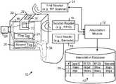
- FIG. 1shows a block diagram of an example system 10 for reading and correlating identifiers relating to an asset.
- the system 10includes an association module 12 .
- the association module 12is communicably connected to each of a first reader 14 , a second reader 16 , a third reader 18 , and a camera 20 .
- An asset 22may be any type of good or other item.
- the asset 22is depicted as a box containing one or more goods or other assets.
- the asset 22may be any type of item.
- the asset 22is associated with tags, including a first asset tag 24 , a second asset tag 26 , and a wireless adhesive product 28 that includes a first adhesive product tag 30 and a second adhesive product tag 32 .
- the first and second asset tags 24 , 26typically are associated with the company and the wireless adhesive product tags 30 , 32 typically are associated with the supplier.
- each of the first asset tag 24 and the second asset tag 26may include either a RFID tag that is associated with a respective a globally unique identification number or a barcode that is associated with a respective a globally unique identification number.
- the barcodemay include any type of one-dimensional barcode (also referred to as a linear barcode) or any type of two-dimensional barcode (also referred to as a matrix barcode).
- the first asset tag 24is a RFID tag
- the second asset tag 26is a barcode
- the first wireless adhesive product tag 30may be any type of RF wireless communications tag
- the second wireless adhesive product tag 32may be any type of RFID tag.
- the first reader 14may be, for example, a wireless RF scanner device that is configured to communicate with the first adhesive product tag 30 of the wireless adhesive product 28 .
- Example wireless RF scanner devicesinclude a Bluetooth scanner (e.g., a Bluetooth Low Energy scanner), a near field communication (NFC) scanner, a LoRaWAN scanner, and a cellular scanner.
- a Bluetooth Low Energy (BLE) scanneris configured to locate and communicate with BLE adhesive product tags within the scanner's range. In this process, the BLE scanner advertises its presence with a specific authentication identifier and credentials. When a BLE adhesive product tag receives data from the BLE scanner, the BLE adhesive product tag establishes a handshake with the BLE scanner on the corresponding advertisement channel.
- the BLE adhesive product taghands off communication with the BLE scanner to a data channel (e.g., a BLE data channel).
- the BLE adhesive product taglearns the BLE scanner's product identification number (PIN) and type identification number (TIN) and transmits that information to a network service to let the network service know that the BLE scanner is communicating with the BLE adhesive product tag.
- PINproduct identification number
- TINtype identification number
- Scanners and peripheral adhesive product tags for LoRaWAN, cellular, ZigBee, and other wireless communicationsoperate in accordance with analogous communications protocols.
- the second reader 16may be, for example, a RFID reader that is configured to interrogate the second wireless adhesive product tag 32 , which is a RFID tag.
- the RFID tag 32may be configured with a fixed packet of read-only data that can be transmitted to a RFID reader (e.g., RFID reader 16 ) within range of the RFID tag 32 .
- the RFID tag 32typically can be reprogrammed with different data, as needed.
- the RFID reader 16may read the RFID tag 32 .
- the typical range of the RFID reader 16may be 10 centimeters to 100 centimeters from the RFID tag 32 .
- the range of the RFID reader 16is approximately 5 centimeters to 20 centimeters from the RFID tag 32 .
- datais transmitted on modulated radio frequency electromagnetic waves between the RFID reader 16 and the RFID tag 32 .
- the RFID reader 16transmits an electric or magnetic field that is sensed by the RFID tag 32 .
- the RFID tag 32transmits data (including a globally unique identification number) that typically is stored in a microchip associated with the RFID tag 32 .
- the RFID tag 32may be an active RFID tag or a passive RFID tag.
- Active RFID tagsinclude local power sources (e.g., batteries) for sending data packets to a RFID reader.
- Passive RFID tagsdo not require any local power sources to transmit data packets to a RFID reader; instead, passive RFID tags are powered by inductive or capacitive coupling between the RFID reader and the RFID tag.
- a passive RFID tagis configured to couple to the magnetic fields generated by a RFID reader.
- each of the RFID reader and the RFID tagincludes a respective set of one or more electrically conducting coils. The RFID reader uses its power source to generate an electric current in the set of coils to generate magnetic fields that induce a current in the set of coils in the RFID tag.
- a passive RFID tagis configured to capacitively couple with a corresponding RFID reader through capacitive coupling plates. In this process, the RFID reader generates an alternating electric field that causes the RFID tag to transfer data to the RFID reader.
- capacitively coupled RFID readers and tagscan only transfer information across short distances and therefore are typically limited to near-field applications.
- the third reader 18may be, for example, a barcode reader that is configured to read the second tag 26 that includes a barcode.
- the barcode reader 18includes a terminal device 34 and a decoder processing unit.
- the terminal device 34may include a light source, a lens, and a light sensor that converts optical impulses reflected from the barcode into electrical signals that are input into a decoder circuit in the decoder processing unit.
- the decoder circuitprocesses the barcode image data captured by the light sensor to generate electrical output data, which may include, for example, a globally unique identification number associated with the barcode.
- the decoder processing unitis incorporated into the local terminal device 34 . In other embodiments, the decoder processing unit is incorporated into a separate processing system (e.g., a network server system).
- the camera 20may be, for example, a still image camera and/or a video camera. In some embodiments, the camera 20 is configured to capture images of at least a portion of the asset 22 . In some examples, the camera 20 is configured to capture an image of a view of each asset moving on an automated conveyor system. In other examples, the camera 20 is configured to automatically detect the locations of tags on the asset 22 and to automatically capture images of one or more views of the tags. In the illustrated example shown in FIG. 1 , the camera 20 is configured to capture an image of the second adhesive product tag 32 and the first asset tag 24 on one side of the asset 22 within the camera view 36 . Other examples may include multiple cameras to capture one or more images of one or more views of the asset 22 .
- two or more of the first reader 14 , the second reader 16 , the third reader 18 , and the camera 20may be integrated into a single component.
- the first reader 14 and the second reader 16may be integrated into a RF scanning component configured to communicate with and read data from the wireless adhesive product 28 and the RFID tag 24 (I.e., the “First Tag”), and the third barcode reader 18 (including the terminal device 34 ) and the camera 20 may be incorporated into an imaging component of the system 10 .
- camera 20may be configured to capture images of the barcodes and send the captured barcode images to an image processing module (e.g., the association module 12 or an intermediate decoder module) that is configured to analyze and process the captured barcode images to generate output data including, for example, the globally unique identification numbers encoded within the barcodes.
- an image processing modulee.g., the association module 12 or an intermediate decoder module
- the camera 20would perform the imaging functions of the third reader 18 (including the terminal device 34 ), and the association module 12 would perform the analyzing and decoder processing functions to generate the output data.
- the wireless adhesive product 28can perform a variety of functions including, for example, adhesive tape functions (e.g., sealing assets) or adhesive label functions (e.g., labeling assets), sensing functions (e.g., monitoring or sensing the status or state of a shipment), and wireless communications functions (e.g., tracking locations of assets and reporting asset status and condition).
- adhesive tape functionse.g., sealing assets
- adhesive label functionse.g., labeling assets
- sensing functionse.g., monitoring or sensing the status or state of a shipment
- wireless communications functionse.g., tracking locations of assets and reporting asset status and condition.
- the supplierprovides the company with the wireless adhesive product 28 , as well as tracking and reporting services.
- the wireless adhesive product 28can be divided into segments, where each segment of the wireless adhesive product includes at least one respective globally unique identifier stored in an memory device embedded in the wireless adhesive product.
- the company and the supplieruse different systems of identifying assets that are packaged and shipped.
- the companyutilizes RFID or barcode tags to identify the company's assets
- the supplierutilizes a wireless adhesive product in the form of a tape or a label that includes a globally unique identifier stored in a memory embedded in the tape or label, along with other components including wireless communications components, data processing components, locationing components, and sensing components.
- the association module 12receives output data generated by two or more of the first reader 14 , the second reader 16 , the third reader 18 , and the camera 20 .
- the association module 12associates the tag data received from two or more of the tags predicated on the tags satisfying a temporal or spatial proximity condition with respect to the asset 22 .
- temporal and spatial proximity conditionsinclude: (1) a determination that one tag and another tag are both physically associated with the same asset; (2) a determination that one tag and another tag both appear in a single image of the asset; (3) a determination that one tag and another tag are read contemporaneously; and (4) a determination that a tag from one source (e.g., the supplier) and a tag from a different source (e.g., the company) are read consecutively where, in some embodiments, the association module 12 generates an error message in response to a determination that that two consecutive tag reads are from the same source (i.e., at least two tags sourced from the supplier are read consecutively, or at least two tags sourced from the company are read consecutively).
- the determination that one tag and another tag are both physically associated with an assetcan be made using short-range scanners that have limited ranges for scanning tags on the asset 22 (e.g., 5 centimeters to 20 centimeters, depending on the size of the asset 22 ).
- short-range scannersinclude short-range RFID scanners and near field communications (NFC) scanners, which have ranges on the order of 5 centimeters to 20 centimeters, for example.
- a determination that one tag and another tag are both physically associated with the asset 22can be made by applying image processing techniques (e.g., barcode decoding techniques) to detect features in an image of the asset 22 that correspond to the two tags.
- image processing techniquese.g., barcode decoding techniques
- a determination that one tag and another tag are read contemporaneouslycan be made when consecutive timestamp data corresponding to the read times of the tags satisfy a temporal proximity condition (e.g., the difference between the read times of the tags is within a specified period of time).
- a determination that a tag from one source (e.g., the supplier) and a tag from a different source (e.g., the company) are read consecutivelycan be made by analyzing a sequence of the timestamp data from a one of the tags to another one of the tags, and determining whether or not an intervening tag was read at a time between the read times of the one tag and the other tag.
- the association module 12is configured with programmatic methods and heuristics for associating an identifier stored in a memory component of the supplier's wireless adhesive product 28 with an identifier generated by the company's identification system. Some of these methods involve “bridging the gap” between the wireless adhesive product identifier of the supplier and the asset identifier of the company through the use of one or more intermediate identifiers.
- the wireless adhesive product 28instead of associating the identifier of the wireless adhesive product 28 directly with the identifier in the company's RFID tag 24 on the asset 22 , the wireless adhesive product 28 includes an RFID tag 32 that can be read contemporaneously with other RFID tags within range of the RFID scanner that are being scanned (e.g., the RFID identifier stored in the first tag 24 ).
- the identifier of the wireless adhesive product 28 and the identifier of the RFID tag 32are embedded in the same segment of the supplier's wireless adhesive product 28 .
- the suppliertypically stores the association between the identifier of the wireless adhesive product 28 and the identifier of the RFID tag 32 in its own association database 38 , which may be stored by the supplier in cloud storage or in the memory of the wireless adhesive product 28 (e.g., the tape or label).
- the association module 12can associate the identifier of the RFID tag 32 with the identifier of RFID tag 24 predicated on the RFID tags 24 , 32 satisfying a temporal or a spatial proximity condition with respect to the asset 22 .
- a determination that the RFID tags 24 and 32 are both physically associated with the asset 22can be made by applying image processing techniques to detect features in a single image of the asset 22 that correspond to the two RFID tags 24 , 32 .
- a determination that the RFID tags 24 and 32 are read contemporaneouslycan be made when consecutive timestamp data corresponding to the read times of the RFID tags 24 and 32 satisfy a temporal proximity condition (e.g., the difference in the read times of the tags are within a specified period of time).
- the third reader 18may be a barcode reader that is configured to read the second tag 26 , which includes a barcode.
- the association module 12can associate the barcode identifier of the second tag 26 with the RFID identifier of the first tag 24 based on a image of the asset 22 that is captured by the camera 20 and includes the first and second tags 24 , 26 within the captured image.
- the association module 12stores the determined chain of associations between the different identifiers in a table 40 of a database 38 .
- the table 40may be used by an asset management system to track assets, monitor the status or state of a particular asset, and report the status and condition of an asset.
- the association database 38includes a table 40 of identifiers organized in a set of rows. Each row of identifiers is associated with a respective asset. For example, row 1 corresponds to the identifiers that are associated with asset 1 , and row 2 corresponds to the identifiers that are associated with asset 2 , and so on.
- Each row of associated identifiersenables the supplier, for example, to generate a report of the location, status, and condition of the associated asset as the asset travels through a logistics network by associating, for example, a scanned bar code identifier or a transmitted RFID data packet with the corresponding wireless adhesive product identifier.
- FIG. 2shows a cross-sectional side view of a portion of an example segment 102 of the wireless adhesive product 28 that includes a respective set of the components of a wireless transducing circuit.
- the flexible adhesive tape platform segment 102includes an adhesive layer 112 , an optional flexible substrate 110 , and an optional adhesive layer 114 on the bottom surface of the flexible substrate 110 . If the bottom adhesive layer 114 is present, a release liner (not shown) may be weakly adhered to the bottom surface of the adhesive layer 114 .
- the adhesive layer 114includes an adhesive (e.g., an acrylic foam adhesive) that has a high bond strength that is sufficient to prevent removal of the adhesive segment 102 from a surface on which the adhesive layer 114 is adhered without destroying the physical or mechanical integrity of the adhesive segment 102 and/or one or more of its constituent components.
- the optional flexible substrate 110is implemented as a prefabricated adhesive tape that includes the adhesive layers 112 , 114 and the optional release liner. In other examples, the adhesive layers 112 , 114 are applied to the top and bottom surfaces of the flexible substrate 110 during the fabrication of the adhesive tape platform 100 .
- the adhesive layer 112bonds the flexible substrate 110 to a bottom surface of a flexible circuit 116 , that includes one or more wiring layers (not shown) that connect the processor 90 , one or more antennas connected to a wireless communications interface 81 (e.g., a low power interface, such as Zigbee or Bluetooth® Low Energy (BLE) interfaces, or other communications interfaces, such as LoRaWAN and cellular interfaces), a timer circuit 83 , transducing and/or energy harvesting component(s) 94 (if present), a memory 96 that stores an identifier (ID) of the wireless adhesive product 28 , an energy storage component 92 , and other components in a device layer 122 that are interconnected through the flexible circuit 116 .
- the wireless communications interface 81typically includes one or more of the antennas 84 , 88 and one or more of the wireless circuits 82 , 86 .
- FIG. 3shows an embodiment of a network 200 that administers wired and wireless network communications between an asset management service 202 and a wireless RF reader 204 and an imaging device 206 .
- the network 200may include one or more of the internet, a private network, a cellular network, a LoRaWAN network, a Bluetooth Low Energy network, and any other suitable communications networks.
- the wireless RF reader 204is configured to read data from one or more types of wireless devices.
- the wireless RF reader 204is configured to retrieve an identifier (ID) 206 of the wireless adhesive product 208 on an asset 210 .
- the wireless RF reader 204executes the process by stepping through the appropriate communications protocol to read the ID 206 stored in the wireless adhesive product.
- the wireless RF reader 204typically includes one or more processors, memory, one or more communications interfaces, and one or more antennas that collectively operate to implement the reading process.
- the imaging device 212may be any suitable type of still image camera or video camera that is configured to capture an image of the asset 210 that includes one or both of the barcodes 214 , 216 .
- the imaging device 212is capable of decoding the barcodes 214 , 216 that are captured in the one or more images.
- the imaging device 212is configured to transmit the captured images of the barcodes 214 , 216 to the network service 202 for processing.
- the network service 202is configured to analyze and decode the barcodes appearing in the images 214 , 216 .
- the asset management service 202controls the operations of the wireless RF reader 204 and the imaging device 212 .
- the asset management service 202also typically manages the process of associating identifiers with one another.
- the asset management service 202is the same entity as the supplier of the wireless adhesive product 208 described above. Therefore, since the supplier/asset management service 202 manufactured the wireless adhesive product 208 , the asset management service 202 readily can associate the identifiers of the wireless adhesive product 208 and the barcode 214 .
- the asset management service 202is configured to store an association between the identifier 206 of the wireless adhesive product 208 and the barcode 214 in the database 218 .
- the asset management service 202also is operable to link the wireless adhesive product identifier 206 with the company's bar code 216 on the asset 210 .
- a linkwould associate the wireless adhesive product identifier 206 with the identifier that is used by the company for the asset and thereby enable the supplier to use the company's identifier associated with the barcode 216 to report information regarding tracking shipment location, status, and other related information.
- a determination that the supplier's barcode tag 214 and the company's barcode tag 216 are both physically associated with the asset 22can be made by applying image processing techniques (e.g., barcode decoding techniques) to detect features that correspond to the two barcode tags 214 , 216 in a single image of the asset 210 .
- image processing techniquese.g., barcode decoding techniques
- a determination that a tag from one source (e.g., the supplier) and a tag from a different source (e.g., the company) are read consecutivelycan be made by analyzing a sequence of the timestamp data from one of the tags to the other and determining whether or not an intervening tag was read at a time between the read times of the two tags.
- FIG. 4shows a flow diagram of an example process of associating identifiers associated with different sources.
- a radio frequency readeris directed to read a first tag attached to an asset and including a first identifier ( FIG. 4 , block 250 ).
- the radio frequency readeris directed to advertise its presence to the first tag and establish a wireless communications channel with the first tag to retrieve the first identifier from the first tag.
- a second readeris instructed to read a second tag attached to the asset and including a second identifier ( FIG. 4 , block 252 ).
- first electromagnetic wavesare directed toward the second tag to receive reflected second electromagnetic waves comprising the second identifier.
- An association between the first identifier and the second identifieris stored predicated on the first tag and the second tag satisfying a temporal or spatial proximity condition ( FIG. 4 , block 254 ).
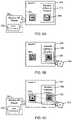
- FIGS. 5A-5Cshow various exemplary systems and methods of reading and correlating identifiers on assets.
- FIG. 5Ashows an example wireless RF reader 300 that includes a RFID transceiver 302 configured to read data from a first RFID tag 304 adhered to an asset 306 and a second RFID tag 308 embedded in a wireless adhesive product 310 adhered to the same asset 306 .
- Each of the RFID tags 304 , 308may be configured with a respective fixed packet of read-only data (including, e.g., a respective tag identifier) that can be wirelessly transmitted to the RFID transceiver 302 of the wireless RF reader 300 .
- the wireless RF reader 300may read the respective identifier and other data from the RFID tags 304 , 308 contemporaneously or consecutively.
- the wireless RF readertransmits the data its reads from the RFID tags 304 , 308 to the network service 202 (see FIG. 3 ).
- the wireless RF reader 300transmits the data to the wireless adhesive product 310 , which stores the data read by the wireless RF reader 300 in the memory component and transmits the stored data to the network service 202 .
- either the wireless RF reader 300 or the wireless adhesive product 310transmits the data read by the wireless RF reader 300 to the network service 202 .
- the network service 202is configured to create an association between the RFID tags 304 , 308 predicated on the tags satisfying a temporal or spatial proximity condition with respect to the asset 306 , as explained herein. Based on a determination that the proximity condition is satisfied, the network service 202 may store the association in the association database 218 or in the memory of the wireless adhesive product adhered to the asset 306 . In some examples, during manufacture of the wireless adhesive product 310 , the network service 202 stores an association between the identifier of the RFID tag 308 and the identifier stored in the wireless adhesive product 310 in the association database 218 or in the memory of the wireless adhesive product 310 . In some examples, the wireless RF reader 300 also is configured to wirelessly communicate with the wireless adhesive product 310 and read the identifier stored in the memory component of the wireless adhesive product 310 .
- FIG. 5Bshows an example of an imaging device 320 that is configured to capture images of visible features on an asset 322 .
- the asset 322includes a first barcode 324 adhered to the asset 322 and a second barcode 326 that is incorporated on the wireless adhesive product 326 .
- Each of the barcodes 324 , 326includes markings that encode respective identifiers and potentially other information.
- the imaging device 320is configured to capture a respective image of each barcode 324 , 326 .
- the imaging device 320also includes processing circuitry and processor executable instructions to read the respective barcodes 324 , 326 .
- the imaging device 320is operable to transmit the captured barcode images to the network service 202 to be decoded.
- the imaging device 320is operable to communicate with the wireless adhesive product 328 , store the captured barcode images in the memory component of the wireless adhesive product, and transmit the captured barcode images or the decoded data to the network service 202 .
- either the imaging device 320 or the wireless adhesive product 328transmits the image data or the decoded image data to the network service 202 .
- the network service 202is configured to create an association between the barcodes 324 , 326 predicated on the tags satisfying a temporal or spatial proximity condition with respect to the asset 322 , as explained herein. Based on a determination that the proximity condition is satisfied, the network service 202 may store the association in the association database 218 or in the memory of the wireless adhesive product 328 adhered to the asset 322 . In some examples, during manufacture of the wireless adhesive product 328 , the network service 202 stores an association between the identifier of the barcode 326 and the identifier stored in the memory component of the wireless adhesive product 328 in the association database 218 or in the memory component of the wireless adhesive product 328 . In some examples, the camera 320 also is configured to wirelessly communicate with the wireless adhesive product 328 and read the identifier stored in the memory component of the wireless adhesive product 328 .
- FIG. 5Cshows an example of an imaging device 350 that is configured to capture images of visible features on an asset 352 .
- the imaging device 350has a 180 degree field of view.
- the asset 352includes a RFID tag 354 adhered to the asset 352 and a barcode 356 that is incorporated on the wireless adhesive product 358 .
- Each of the RFID tag 354 and the barcode 356stores respective identifiers and potentially other information.
- the wireless RF reader 351includes a RFID transceiver 353 that is configured to read data from the RFID tag 354 adhered to the asset 352 .
- the RFID tag 354may be configured with a respective fixed packet of read-only data (e.g., a respective tag identifier) that can be wirelessly transmitted to the RFID transceiver 353 of the wireless RF reader 351 .
- the wireless RF reader 351may read the respective identifier and other data from the RFID tag 354 contemporaneously or consecutively
- the imaging device 350is configured to capture a respective image of the barcode 356 .
- the imaging device 350also includes processing circuitry and executable instructions to read the barcode 356 .
- the imaging device 350is operable to transmit the captured barcode image to the network service 202 to be decoded.
- the imaging device 350is operable to communicate wirelessly with the wireless adhesive product 358 , store the captured barcode image in the memory component of the wireless adhesive product 358 , and transmit the captured barcode image or the decoded barcode data to the network service 202 .
- either the imaging device 350 or the wireless adhesive product 358may transmit the image data or the decoded image data to the network service 202 .
- the network service 202is configured to create an association between the RFID tag 354 and the barcode 356 predicated on the tags satisfying a temporal or spatial proximity condition with respect to the asset 322 , as explained herein.
- the spatial proximity conditionis satisfied in response to a determination that the imaging device 350 captured the RFID tag 354 and the barcode 356 on the asset 352 in a single image. Based on a determination that the proximity condition is satisfied, the network service 202 may store the association between the RFID tag 354 and the barcode 356 in the association database 218 or in the memory of the wireless adhesive product 358 adhered to the asset 352 .
- the network service 202stores an association between the identifier of the barcode 356 and the identifier of the RFID tag 354 in the association database 218 or in the memory of the wireless adhesive product 328 .
- the imaging device 350also is configured to wirelessly communicate with the wireless adhesive product 328 and read the identifiers stored in the memory component of the wireless adhesive product 358 .
- FIG. 6shows a conveyor system 370 configured to convey assets through a scanning zone 372 configured with a wireless RF reader 374 and an imaging device 376 to implement an automated process for reading and associating asset identifiers.
- the wireless RF reader 374 and the imaging device 376are configured to perform one or more of the reader operations and identifier association operations that are described above.
- the illustrated embodimentshows the asset 306 (“Asset 1 ”), the asset 322 (“Asset 2 ”), and the asset 352 (“Asset 13 ”) being conveyed on, for example, a conveyor belt or on rollers, past the wireless RF reader 374 and the imaging device 376 in a first-in, first out (FIFO) order.
- the wireless RF reader 374 and the imaging device 376may be configured in accordance with the embodiments described above in connection with FIGS. 5A-5C .
- FIG. 7shows an example embodiment of computer apparatus that is configured to implement one or more of the computing systems described in this specification.
- the computer apparatus 420includes a processing unit 422 , a system memory 424 , and a system bus 426 that couples the processing unit 422 to the various components of the computer apparatus 420 .
- the processing unit 422may include one or more data processors, each of which may be in the form of any one of various commercially available computer processors.
- the system memory 424includes one or more computer-readable media that typically are associated with a software application addressing space that defines the addresses that are available to software applications.
- the system memory 424may include a read only memory (ROM) that stores a basic input/output system (BIOS) that contains start-up routines for the computer apparatus 420 , and a random access memory (RAM).
- ROMread only memory
- BIOSbasic input/output system
- RAMrandom access memory
- the system bus 426may be a memory bus, a peripheral bus or a local bus, and may be compatible with any of a variety of bus protocols, including PCI, VESA, Microchannel, ISA, and EISA.
- the computer apparatus 420also includes a persistent storage memory 428 (e.g., a hard drive, a floppy drive, a CD ROM drive, magnetic tape drives, flash memory devices, and digital video disks) that is connected to the system bus 426 and contains one or more computer-readable media disks that provide non-volatile or persistent storage for data, data structures and computer-executable instructions.
- a persistent storage memory 428e.g., a hard drive, a floppy drive, a CD ROM drive, magnetic tape drives, flash memory devices, and digital video disks
- a usermay interact (e.g., input commands or data) with the computer apparatus 420 using one or more input devices 430 (e.g. one or more keyboards, computer mice, microphones, cameras, joysticks, physical motion sensors, and touch pads). Information may be presented through a graphical user interface (GUI) that is presented to the user on a display monitor 432 , which is controlled by a display controller 434 .
- GUIgraphical user interface
- the computer apparatus 320also may include other input/output hardware (e.g., peripheral output devices, such as speakers and a printer).
- the computer apparatus 420connects to other network nodes through a network adapter 336 (also referred to as a “network interface card” or NIC).
- NICnetwork interface card
- a number of program modulesmay be stored in the system memory 424 , including application programming interfaces 438 (APIs), an operating system (OS) 440 (e.g., the Windows® operating system available from Microsoft Corporation of Redmond, Wash. U.S.A.), software applications 441 including one or more software applications programming the computer apparatus 420 to perform one or more of the steps, tasks, operations, or processes of the hierarchical classification systems described herein, drivers 442 (e.g., a GUI driver), network transport protocols 444 , and data 446 (e.g., input data, output data, program data, a registry, and configuration settings).
- APIsapplication programming interfaces 438
- OSoperating system
- software applications 441including one or more software applications programming the computer apparatus 420 to perform one or more of the steps, tasks, operations, or processes of the hierarchical classification systems described herein
- drivers 442e.g., a GUI driver
- network transport protocols 444e.g., input data, output data, program data, a registry, and
- Examples of the subject matter described hereincan be implemented in data processing apparatus (e.g., computer hardware and digital electronic circuitry) operable to perform functions by operating on input and generating output. Examples of the subject matter described herein also can be tangibly embodied in software or firmware, as one or more sets of computer instructions encoded on one or more tangible non-transitory carrier media (e.g., a machine readable storage device, substrate, or sequential access memory device) for execution by data processing apparatus.
- data processing apparatuse.g., computer hardware and digital electronic circuitry
- Examples of the subject matter described hereinalso can be tangibly embodied in software or firmware, as one or more sets of computer instructions encoded on one or more tangible non-transitory carrier media (e.g., a machine readable storage device, substrate, or sequential access memory device) for execution by data processing apparatus.
- tangible non-transitory carrier mediae.g., a machine readable storage device, substrate, or sequential access memory device
Landscapes
- Engineering & Computer Science (AREA)
- Theoretical Computer Science (AREA)
- Business, Economics & Management (AREA)
- Physics & Mathematics (AREA)
- General Physics & Mathematics (AREA)
- Computer Hardware Design (AREA)
- Microelectronics & Electronic Packaging (AREA)
- Accounting & Taxation (AREA)
- Computer Networks & Wireless Communication (AREA)
- Signal Processing (AREA)
- Computer Security & Cryptography (AREA)
- Finance (AREA)
- Strategic Management (AREA)
- General Business, Economics & Management (AREA)
- Chemical & Material Sciences (AREA)
- Organic Chemistry (AREA)
Abstract
Description
Claims (21)
Priority Applications (5)
| Application Number | Priority Date | Filing Date | Title |
|---|---|---|---|
| US16/839,048US11295190B2 (en) | 2016-12-14 | 2020-04-02 | Correlated asset identifier association |
| US17/067,608US11308370B2 (en) | 2019-04-04 | 2020-10-09 | Correlating asset identifiers |
| US17/679,992US12236303B2 (en) | 2016-12-14 | 2022-02-24 | Correlated asset identifier association |
| US17/683,738US11816514B2 (en) | 2019-04-04 | 2022-03-01 | Correlating asset identifiers |
| US18/378,121US12373660B2 (en) | 2019-04-04 | 2023-10-09 | Correlating asset identifiers |
Applications Claiming Priority (8)
| Application Number | Priority Date | Filing Date | Title |
|---|---|---|---|
| US201662434218P | 2016-12-14 | 2016-12-14 | |
| US201662435207P | 2016-12-16 | 2016-12-16 | |
| US15/842,867US10445634B2 (en) | 2016-12-14 | 2017-12-14 | Fabricating multifunction adhesive product for ubiquitous realtime tracking |
| US15/842,861US10262255B2 (en) | 2016-12-14 | 2017-12-14 | Multifunction adhesive product for ubiquitous realtime tracking |
| US201962829627P | 2019-04-04 | 2019-04-04 | |
| US16/383,353US10872286B2 (en) | 2016-12-14 | 2019-04-12 | Wake circuit for flexible adhesive product |
| US16/581,599US11328201B2 (en) | 2016-12-14 | 2019-09-24 | Roll-to-roll method of fabricating a wireless multi-layer laminate |
| US16/839,048US11295190B2 (en) | 2016-12-14 | 2020-04-02 | Correlated asset identifier association |
Related Parent Applications (2)
| Application Number | Title | Priority Date | Filing Date |
|---|---|---|---|
| US16/383,353Continuation-In-PartUS10872286B2 (en) | 2016-12-14 | 2019-04-12 | Wake circuit for flexible adhesive product |
| US16/581,599Continuation-In-PartUS11328201B2 (en) | 2016-12-14 | 2019-09-24 | Roll-to-roll method of fabricating a wireless multi-layer laminate |
Related Child Applications (3)
| Application Number | Title | Priority Date | Filing Date |
|---|---|---|---|
| US16/383,353ContinuationUS10872286B2 (en) | 2016-12-14 | 2019-04-12 | Wake circuit for flexible adhesive product |
| US17/067,608Continuation-In-PartUS11308370B2 (en) | 2019-04-04 | 2020-10-09 | Correlating asset identifiers |
| US17/679,992ContinuationUS12236303B2 (en) | 2016-12-14 | 2022-02-24 | Correlated asset identifier association |
Publications (2)
| Publication Number | Publication Date |
|---|---|
| US20200234098A1 US20200234098A1 (en) | 2020-07-23 |
| US11295190B2true US11295190B2 (en) | 2022-04-05 |
Family
ID=71609033
Family Applications (2)
| Application Number | Title | Priority Date | Filing Date |
|---|---|---|---|
| US16/839,048Active2038-01-08US11295190B2 (en) | 2016-12-14 | 2020-04-02 | Correlated asset identifier association |
| US17/679,992ActiveUS12236303B2 (en) | 2016-12-14 | 2022-02-24 | Correlated asset identifier association |
Family Applications After (1)
| Application Number | Title | Priority Date | Filing Date |
|---|---|---|---|
| US17/679,992ActiveUS12236303B2 (en) | 2016-12-14 | 2022-02-24 | Correlated asset identifier association |
Country Status (1)
| Country | Link |
|---|---|
| US (2) | US11295190B2 (en) |
Cited By (4)
| Publication number | Priority date | Publication date | Assignee | Title |
|---|---|---|---|---|
| US20220292323A1 (en)* | 2016-12-14 | 2022-09-15 | Trackonomy Systems, Inc. | Correlated asset identifier association |
| US12153990B2 (en) | 2019-11-19 | 2024-11-26 | Trackonomy Systems, Inc. | Associating assets using RFID-RF wireless gateways |
| US12363512B2 (en) | 2021-07-25 | 2025-07-15 | Trackonomy Systems, Inc. | Multi-communication-interface system for fine locationing |
| US12373660B2 (en) | 2019-04-04 | 2025-07-29 | Trackonomy Systems, Inc. | Correlating asset identifiers |
Families Citing this family (9)
| Publication number | Priority date | Publication date | Assignee | Title |
|---|---|---|---|---|
| JP6278283B1 (en)* | 2016-08-29 | 2018-02-14 | 日本電気株式会社 | Tag management device, tag management method, program |
| US10819137B2 (en) | 2016-12-14 | 2020-10-27 | Ajay Khoche | Energy harvesting wireless sensing system |
| US11587425B1 (en) | 2020-05-17 | 2023-02-21 | Trackonomy Systems, Inc. | Next generation building access control, indoor locationing, and interaction tracking |
| US10966059B1 (en)* | 2020-07-16 | 2021-03-30 | Siemens Industry, Inc. | Location tracking and distance monitoring system and associated method |
| WO2022125599A1 (en)* | 2020-12-07 | 2022-06-16 | Trackonomy Systems, Inc. | Method and system for performing ad hoc diagnostics, maintenance, programming, and tests of internet of things devices |
| US20230155699A1 (en)* | 2021-11-17 | 2023-05-18 | Commscope Technologies Llc | Methods of storing and retrieving active antenna unit calibration data and related active antenna modules and methods of calibrating same |
| CN118433852A (en)* | 2023-02-01 | 2024-08-02 | 维沃移动通信有限公司 | Positioning method, device, communication equipment and readable storage medium |
| SE2330099A1 (en)* | 2023-02-22 | 2024-08-23 | Beescanning Global Ab | Method to generate a product code that verifies the authenticity and origin of a commodity |
| WO2025094179A2 (en)* | 2023-10-30 | 2025-05-08 | Zimark Ltd. | A physical substrate, a set of physical substrates, and methods and systems for management of physical assets using the physical substrates |
Citations (52)
| Publication number | Priority date | Publication date | Assignee | Title |
|---|---|---|---|---|
| US5495250A (en) | 1993-11-01 | 1996-02-27 | Motorola, Inc. | Battery-powered RF tags and apparatus for manufacturing the same |
| US6375780B1 (en) | 1992-06-17 | 2002-04-23 | Micron Technology, Inc. | Method of manufacturing an enclosed transceiver |
| US6614392B2 (en) | 2001-12-07 | 2003-09-02 | Delaware Capital Formation, Inc. | Combination RFID and GPS functionality on intelligent label |
| US20040044493A1 (en) | 2002-08-27 | 2004-03-04 | Coulthard John J. | Monitoring system |
| US20050099292A1 (en) | 2003-06-17 | 2005-05-12 | United Security Applications Id, Inc. | Electronic security system for monitoring and recording activity and data relating to cargo |
| US7048194B2 (en) | 2002-03-27 | 2006-05-23 | Seiko Epson Corporation | Printing paper with memory element mounted thereon and printing technique using such printing paper |
| US7177054B2 (en) | 1999-05-25 | 2007-02-13 | Silverbrook Research Pty Ltd | Interactive printer |
| US20070049291A1 (en) | 2005-08-29 | 2007-03-01 | Samsung Electronics Co., Ltd. | Method and system for indoor positioning using mobile terminal |
| US7299990B2 (en) | 2005-01-28 | 2007-11-27 | Seiko Epson Corporation | RFID tag, printing paper, printer, and RFID system |
| US20070287473A1 (en) | 1998-11-24 | 2007-12-13 | Tracbeam Llc | Platform and applications for wireless location and other complex services |
| US7405656B2 (en) | 2004-01-30 | 2008-07-29 | United Parcel Service Of America, Inc. | Device and method for encapsulation and mounting of RFID devices |
| US20080198022A1 (en) | 2007-02-21 | 2008-08-21 | Imation Corp. | Inkjet printable RFID label and method of printing an inkjet printable RFID label |
| US20080198002A1 (en) | 2007-02-16 | 2008-08-21 | Joel Bartholf | Flexible anti-theft pack for tracking and location |
| JP2008239282A (en) | 2007-03-26 | 2008-10-09 | Brother Ind Ltd | Delivery system and RFID tag information reader |
| US7511616B2 (en) | 1998-02-12 | 2009-03-31 | Keystone Technology Solutions, Llc | Thin profile battery bonding method, method of conductively interconnecting electronic components, battery powerable apparatus, radio frequency communication device, and electric circuit |
| US7540603B2 (en) | 2001-11-21 | 2009-06-02 | Seiko Epson Corporation | Printed body, element provided on printed body, printer, and computer system |
| US20090174600A1 (en) | 2008-01-03 | 2009-07-09 | Commscope, Inc. Of North Carolina | System and method for determining the geographic location of a device |
| US20090192709A1 (en) | 2008-01-25 | 2009-07-30 | Garmin Ltd. | Position source selection |
| US20100089803A1 (en) | 2008-10-10 | 2010-04-15 | Leroy Sina Lavi | System and method for sorting specimen |
| US7743984B2 (en) | 2004-10-29 | 2010-06-29 | United Parcel Service Of America, Inc. | Systems and methods for tracking items using wirelessly-enabled devices |
| US7838844B2 (en) | 2005-10-03 | 2010-11-23 | Mallinckrodt Inc. | Radiopharmaceutical system and method utilizing radio-frequency identification tags |
| US20110062237A1 (en) | 2009-09-17 | 2011-03-17 | Sap Ag | Integrated smart label |
| JP2011090670A (en) | 2009-09-24 | 2011-05-06 | Terrara Code Research Institute Inc | Rfid tag, tag reader/writer, data management system and data management method |
| US20110139871A1 (en) | 2009-12-15 | 2011-06-16 | Carefusion 303, Inc. | Methods and systems for tracking inventory using an rfid tag tape |
| US8016194B2 (en) | 2008-03-06 | 2011-09-13 | Imation Corp. | Mobile data storage device reader having both radiofrequency and barcode scanners |
| US8072620B2 (en) | 2003-12-26 | 2011-12-06 | Konica Minolta Business Technologies, Inc. | Electronically tagged printed matter, image forming device, image forming method, and image forming program, as well as computer readable recording medium on which the program is recorded |
| US8171791B2 (en) | 2009-05-13 | 2012-05-08 | Robert Bosch Gmbh | Rotation sensor with onboard power generation |
| JP2012141995A (en) | 2012-02-08 | 2012-07-26 | Mitsubishi Electric Information Systems Corp | Warning system |
| US20120256728A1 (en) | 2011-04-08 | 2012-10-11 | Savi Technology, Inc. | Hierarchical fast collection procedure |
| US8317230B2 (en)* | 2001-04-23 | 2012-11-27 | Asay Jon L | Method of labeling a package for shipment |
| US20130250357A1 (en) | 2012-03-26 | 2013-09-26 | Brother Kogyo Kabushiki Kaisha | Printer |
| US8581701B2 (en) | 2010-05-24 | 2013-11-12 | Barcoding, Inc. | RFID-based data collection, correlation and transmission system, and method for collecting data and correlating same to system participant identities and actions thereof |
| US20140159869A1 (en) | 2012-12-07 | 2014-06-12 | Hand Held Products Inc. | Reading rfid tags in defined spatial locations |
| US20140240088A1 (en) | 2011-03-22 | 2014-08-28 | Jamie Robinette | Apparatus and method for locating, tracking, controlling and recognizing tagged objects using active rfid technology |
| US8833664B2 (en) | 2009-12-18 | 2014-09-16 | Yu Yung Choi | Enhanced performance and security RFID device |
| US20140263634A1 (en) | 2013-03-15 | 2014-09-18 | Shazi Iqbal | Specimen reader employing optical and rfid scanning |
| US20150097674A1 (en) | 2013-10-07 | 2015-04-09 | Recon Dynamics, Llc | System and method for automatic tool tracking, monitoring, and inventory management |
| US20150349667A1 (en) | 2014-05-29 | 2015-12-03 | Microgen Systems, Inc. | Internal vibration impulsed broadband excitation energy harvester systems and methods |
| US20160011074A1 (en) | 2013-02-05 | 2016-01-14 | International Electronic Machines Corporation | Pressure Profiling System |
| US20160026213A1 (en) | 2014-07-25 | 2016-01-28 | VivaLnk Limited (Cayman Islands) | Highly compliant wearable wireless patch having stress-relief capability |
| US9251459B2 (en) | 2010-07-09 | 2016-02-02 | Hewlett-Packard Development Company, L.P. | RFID antenna and 2D barcode |
| US9305283B1 (en) | 2014-12-17 | 2016-04-05 | Amazon Technologies, Inc. | Association of item identifiers |
| US20160205509A1 (en) | 2015-01-14 | 2016-07-14 | Tektronix, Inc. | Mechanism for determining location history via multiple historical predictors |
| US20170011606A1 (en) | 2015-07-07 | 2017-01-12 | Stefano Ceccon | Systems, Devices, and/or Methods for Managing Transactions |
| US20170083857A1 (en)* | 2015-09-17 | 2017-03-23 | James D. Barton | Gps shipping and temperature sensor label |
| US9643460B2 (en) | 2014-07-18 | 2017-05-09 | Infineon Technologies Ag | Tire pressure sensor modules, tire pressure monitoring system, wheel, methods and computer programs for providing information related to a tire pressure |
| US9644401B2 (en) | 2013-03-12 | 2017-05-09 | Spectrum Brands, Inc. | Electronic lockset with multi-source energy harvesting circuit |
| US20170286903A1 (en) | 2016-04-01 | 2017-10-05 | Meps Real-Time, Inc. | Rfid read system for verifying the contents of items in tray pockets |
| US20170337405A1 (en) | 2014-11-04 | 2017-11-23 | Idp Invent Ag | Transponder tag that is operable by a mobile telephone, portable object, mobile telephone, and corresponding methods |
| US20180163095A1 (en) | 2016-12-14 | 2018-06-14 | Trackonomy Systems, Inc. | Multifunction Adhesive Product For Ubiquitous Realtime Tracking |
| US10095898B2 (en) | 2013-03-15 | 2018-10-09 | Shazi Iqbal | Method of specimen tracking via barcode and RFID correlation at accession time |
| US20190087702A1 (en) | 2017-09-15 | 2019-03-21 | Avery Dennison Retail Information Services, Llc | System for barcode scanning and rfid label printing |
Family Cites Families (53)
| Publication number | Priority date | Publication date | Assignee | Title |
|---|---|---|---|---|
| US7041941B2 (en) | 1997-04-07 | 2006-05-09 | Patented Medical Solutions, Llc | Medical item thermal treatment systems and method of monitoring medical items for compliance with prescribed requirements |
| US8786437B2 (en) | 2000-09-08 | 2014-07-22 | Intelligent Technologies International, Inc. | Cargo monitoring method and arrangement |
| US6816075B2 (en) | 2001-02-21 | 2004-11-09 | 3M Innovative Properties Company | Evidence and property tracking for law enforcement |
| US6861954B2 (en) | 2001-03-30 | 2005-03-01 | Bruce H. Levin | Tracking medical products with integrated circuits |
| US8616984B2 (en) | 2002-06-12 | 2013-12-31 | Igt | Intelligent player tracking card and wagering token tracking techniques |
| US7187286B2 (en) | 2004-03-19 | 2007-03-06 | Applera Corporation | Methods and systems for using RFID in biological field |
| JP4458904B2 (en) | 2004-04-02 | 2010-04-28 | 東芝テック株式会社 | Issuing device |
| US7124943B2 (en) | 2004-09-24 | 2006-10-24 | Assa Abloy Identification Technology Group Ab | RFID system having a field reprogrammable RFID reader |
| US20060226957A1 (en) | 2004-11-15 | 2006-10-12 | Miller Ronald H | Health care operating system with radio frequency information transfer |
| DE102005001034A1 (en) | 2005-01-07 | 2006-07-20 | Deutsche Telekom Ag | Transport monitoring system |
| US7275682B2 (en) | 2005-03-24 | 2007-10-02 | Varian, Inc. | Sample identification utilizing RFID tags |
| US7659819B2 (en) | 2005-04-21 | 2010-02-09 | Skyetek, Inc. | RFID reader operating system and associated architecture |
| US8231749B2 (en)* | 2005-06-02 | 2012-07-31 | Automed Technologies, Inc. | Apparatus and methods for dispensing pre-filled containers with precisely-applied patient-specific information |
| US7538670B2 (en) | 2005-06-20 | 2009-05-26 | Sun Microsystems, Inc. | Method for detecting objects separated from a group |
| US7916023B2 (en) | 2006-01-31 | 2011-03-29 | Zebra Enterprise Solutions Corp. | System and method for tracking assets within a monitored environment |
| US8917178B2 (en) | 2006-06-09 | 2014-12-23 | Dominic M. Kotab | RFID system and method for storing information related to a vehicle or an owner of the vehicle |
| EP2329419A4 (en) | 2008-09-15 | 2016-01-13 | James A Aman | Session automated recording together with rules based indexing, analysis and expression of content |
| WO2010056287A1 (en) | 2008-10-30 | 2010-05-20 | Tagent Corporation | Rfid tracking of patient specimen samples |
| US20100201520A1 (en) | 2009-02-12 | 2010-08-12 | Symbol Technologies, Inc. | System for determining item location based on feedback from fixed radio frequency identification (rfid) readers and/or fixed rfid beacon tags |
| WO2011038018A1 (en) | 2009-09-23 | 2011-03-31 | Earthsearch Communications International, Inc. | Device and process for monitoring secure storage and delivery of items |
| US8686685B2 (en) | 2009-12-25 | 2014-04-01 | Golba, Llc | Secure apparatus for wirelessly transferring power and communicating with one or more slave devices |
| US9431692B2 (en) | 2011-04-07 | 2016-08-30 | Biotillion, Llc | Tracking biological and other samples using RFID tags |
| US10192157B2 (en) | 2011-05-10 | 2019-01-29 | Omni-Id Cayman Limited | Visual RFID tags and interactive visual RFID networks |
| US9202193B2 (en) | 2011-06-22 | 2015-12-01 | Hana Micron America, Inc. | Early alert system and method for livestock disease detection |
| US9330287B2 (en) | 2012-03-02 | 2016-05-03 | Rf Code, Inc. | Real-time asset tracking and event association |
| US20130282392A1 (en) | 2012-04-20 | 2013-10-24 | Scott Wurm | System and method of securely storing, dispensing, and inventorying medications and samples |
| US8989053B1 (en) | 2013-11-29 | 2015-03-24 | Fedex Corporate Services, Inc. | Association management in a wireless node network |
| GB2539133B (en) | 2014-04-02 | 2021-02-10 | Walmart Apollo Llc | Apparatus and method of determining an open status of a container using RFID tag devices |
| US10453023B2 (en) | 2014-05-28 | 2019-10-22 | Fedex Corporate Services, Inc. | Methods and node apparatus for adaptive node communication within a wireless node network |
| US20150379860A1 (en) | 2014-06-27 | 2015-12-31 | Techip International Limited | System and methods of tracking using radio frequency identification |
| WO2016010653A1 (en) | 2014-07-16 | 2016-01-21 | Clairvoyant Technology Llc | Rfid tag tracking using phase likelihood |
| US9817947B2 (en) | 2014-10-27 | 2017-11-14 | Zih Corp. | Method and apparatus for managing remote devices and accessing remote device information |
| FR3032531B1 (en) | 2015-02-06 | 2017-03-10 | Total Marketing Services | INSTALLATION AND METHOD FOR MONITORING THE EVOLUTION OF THE BASICITY OF A LUBRICANT |
| US10319203B1 (en) | 2015-04-15 | 2019-06-11 | Cellotape, Inc. | Track and trace device, systems and methods thereof |
| US11810032B2 (en) | 2016-03-16 | 2023-11-07 | Triax Technologies, Inc. | Systems and methods for low-energy wireless applications using networked wearable sensors |
| US10074072B2 (en) | 2016-07-01 | 2018-09-11 | Intel Corporation | Tagged item locator method and apparatus |
| DE102016218603A1 (en) | 2016-09-27 | 2018-03-29 | Jost-Werke Deutschland Gmbh | Device for detecting the position of a first or second vehicle to be coupled together |
| US10885420B2 (en) | 2016-12-14 | 2021-01-05 | Ajay Khoche | Package sealing tape types with varied transducer sampling densities |
| US10819137B2 (en) | 2016-12-14 | 2020-10-27 | Ajay Khoche | Energy harvesting wireless sensing system |
| US11295190B2 (en) | 2016-12-14 | 2022-04-05 | Hendrik J Volkerink | Correlated asset identifier association |
| US11138490B2 (en) | 2016-12-14 | 2021-10-05 | Ajay Khoche | Hierarchical combination of distributed statistics in a monitoring network |
| US11003978B2 (en) | 2016-12-14 | 2021-05-11 | Ajay Khoche | Programmable network node roles in hierarchical communications network |
| EP3416114A1 (en) | 2017-06-15 | 2018-12-19 | Flex, Ltd. | System and method for assessing the insurance risk of driver behavior using gps tracking and machine learning |
| CA3008525A1 (en) | 2017-06-15 | 2018-12-15 | Flex Ltd. | Systems and methods for hybrid cloud-edge computing method for automated decision making and probabilistic occurrence |
| EP3416127A1 (en) | 2017-06-15 | 2018-12-19 | Flex, Ltd. | System and method for building multiple gps trackers from a common core |
| WO2019224282A1 (en) | 2018-05-22 | 2019-11-28 | Pick8Ship Technology Ag | Transfer station configured to handle cargo and cargo receptacle sorting method |
| WO2019232329A1 (en) | 2018-06-01 | 2019-12-05 | Capital One Services, Llc | Beacon-triggered activation of a near field communication application |
| US11019567B2 (en) | 2019-02-26 | 2021-05-25 | Chadra Laboratories Llc | Multi-interface transponder device-altering power modes |
| US11308370B2 (en) | 2019-04-04 | 2022-04-19 | Trackonomy Systems, Inc. | Correlating asset identifiers |
| US11487958B2 (en) | 2019-10-13 | 2022-11-01 | Trackonomy Systems, Inc. | Systems and methods for monitoring loading of cargo onto a transport vehicle |
| US12381622B2 (en) | 2019-11-08 | 2025-08-05 | Zebra Technologies Corporation | Systems and methods to co-locate RFID reader networks with in-band sensor networks |
| US11907796B2 (en) | 2019-11-19 | 2024-02-20 | Trackonomy Systems, Inc. | Associating assets using RFID-RF wireless gateways |
| US11775780B2 (en) | 2021-03-01 | 2023-10-03 | Raymond Anthony Joao | Personal monitoring apparatus and methods |
- 2020
- 2020-04-02USUS16/839,048patent/US11295190B2/enactiveActive
- 2022
- 2022-02-24USUS17/679,992patent/US12236303B2/enactiveActive
Patent Citations (54)
| Publication number | Priority date | Publication date | Assignee | Title |
|---|---|---|---|---|
| US6375780B1 (en) | 1992-06-17 | 2002-04-23 | Micron Technology, Inc. | Method of manufacturing an enclosed transceiver |
| US5495250A (en) | 1993-11-01 | 1996-02-27 | Motorola, Inc. | Battery-powered RF tags and apparatus for manufacturing the same |
| US7511616B2 (en) | 1998-02-12 | 2009-03-31 | Keystone Technology Solutions, Llc | Thin profile battery bonding method, method of conductively interconnecting electronic components, battery powerable apparatus, radio frequency communication device, and electric circuit |
| US20070287473A1 (en) | 1998-11-24 | 2007-12-13 | Tracbeam Llc | Platform and applications for wireless location and other complex services |
| US7177054B2 (en) | 1999-05-25 | 2007-02-13 | Silverbrook Research Pty Ltd | Interactive printer |
| US8317230B2 (en)* | 2001-04-23 | 2012-11-27 | Asay Jon L | Method of labeling a package for shipment |
| US7540603B2 (en) | 2001-11-21 | 2009-06-02 | Seiko Epson Corporation | Printed body, element provided on printed body, printer, and computer system |
| US6614392B2 (en) | 2001-12-07 | 2003-09-02 | Delaware Capital Formation, Inc. | Combination RFID and GPS functionality on intelligent label |
| US7048194B2 (en) | 2002-03-27 | 2006-05-23 | Seiko Epson Corporation | Printing paper with memory element mounted thereon and printing technique using such printing paper |
| US20040044493A1 (en) | 2002-08-27 | 2004-03-04 | Coulthard John J. | Monitoring system |
| US20050099292A1 (en) | 2003-06-17 | 2005-05-12 | United Security Applications Id, Inc. | Electronic security system for monitoring and recording activity and data relating to cargo |
| US8072620B2 (en) | 2003-12-26 | 2011-12-06 | Konica Minolta Business Technologies, Inc. | Electronically tagged printed matter, image forming device, image forming method, and image forming program, as well as computer readable recording medium on which the program is recorded |
| US7405656B2 (en) | 2004-01-30 | 2008-07-29 | United Parcel Service Of America, Inc. | Device and method for encapsulation and mounting of RFID devices |
| US7743984B2 (en) | 2004-10-29 | 2010-06-29 | United Parcel Service Of America, Inc. | Systems and methods for tracking items using wirelessly-enabled devices |
| US7299990B2 (en) | 2005-01-28 | 2007-11-27 | Seiko Epson Corporation | RFID tag, printing paper, printer, and RFID system |
| US20070049291A1 (en) | 2005-08-29 | 2007-03-01 | Samsung Electronics Co., Ltd. | Method and system for indoor positioning using mobile terminal |
| US7838844B2 (en) | 2005-10-03 | 2010-11-23 | Mallinckrodt Inc. | Radiopharmaceutical system and method utilizing radio-frequency identification tags |
| US20080198002A1 (en) | 2007-02-16 | 2008-08-21 | Joel Bartholf | Flexible anti-theft pack for tracking and location |
| US20080198022A1 (en) | 2007-02-21 | 2008-08-21 | Imation Corp. | Inkjet printable RFID label and method of printing an inkjet printable RFID label |
| JP2008239282A (en) | 2007-03-26 | 2008-10-09 | Brother Ind Ltd | Delivery system and RFID tag information reader |
| US20090174600A1 (en) | 2008-01-03 | 2009-07-09 | Commscope, Inc. Of North Carolina | System and method for determining the geographic location of a device |
| US20090192709A1 (en) | 2008-01-25 | 2009-07-30 | Garmin Ltd. | Position source selection |
| US8016194B2 (en) | 2008-03-06 | 2011-09-13 | Imation Corp. | Mobile data storage device reader having both radiofrequency and barcode scanners |
| US20100089803A1 (en) | 2008-10-10 | 2010-04-15 | Leroy Sina Lavi | System and method for sorting specimen |
| US8171791B2 (en) | 2009-05-13 | 2012-05-08 | Robert Bosch Gmbh | Rotation sensor with onboard power generation |
| US20110062237A1 (en) | 2009-09-17 | 2011-03-17 | Sap Ag | Integrated smart label |
| JP2011090670A (en) | 2009-09-24 | 2011-05-06 | Terrara Code Research Institute Inc | Rfid tag, tag reader/writer, data management system and data management method |
| US20120278676A1 (en) | 2009-09-24 | 2012-11-01 | Japan Nus Co., Ltd | Rfid tag, tag reader/writer, data management system and data management method |
| US20110139871A1 (en) | 2009-12-15 | 2011-06-16 | Carefusion 303, Inc. | Methods and systems for tracking inventory using an rfid tag tape |
| US8292173B2 (en) | 2009-12-15 | 2012-10-23 | Carefusion 303, Inc. | Methods and systems for tracking inventory using an RFID tag tape |
| US8833664B2 (en) | 2009-12-18 | 2014-09-16 | Yu Yung Choi | Enhanced performance and security RFID device |
| US8581701B2 (en) | 2010-05-24 | 2013-11-12 | Barcoding, Inc. | RFID-based data collection, correlation and transmission system, and method for collecting data and correlating same to system participant identities and actions thereof |
| US9251459B2 (en) | 2010-07-09 | 2016-02-02 | Hewlett-Packard Development Company, L.P. | RFID antenna and 2D barcode |
| US20140240088A1 (en) | 2011-03-22 | 2014-08-28 | Jamie Robinette | Apparatus and method for locating, tracking, controlling and recognizing tagged objects using active rfid technology |
| US20120256728A1 (en) | 2011-04-08 | 2012-10-11 | Savi Technology, Inc. | Hierarchical fast collection procedure |
| JP2012141995A (en) | 2012-02-08 | 2012-07-26 | Mitsubishi Electric Information Systems Corp | Warning system |
| US20130250357A1 (en) | 2012-03-26 | 2013-09-26 | Brother Kogyo Kabushiki Kaisha | Printer |
| US20140159869A1 (en) | 2012-12-07 | 2014-06-12 | Hand Held Products Inc. | Reading rfid tags in defined spatial locations |
| US20160011074A1 (en) | 2013-02-05 | 2016-01-14 | International Electronic Machines Corporation | Pressure Profiling System |
| US9644401B2 (en) | 2013-03-12 | 2017-05-09 | Spectrum Brands, Inc. | Electronic lockset with multi-source energy harvesting circuit |
| US20140263634A1 (en) | 2013-03-15 | 2014-09-18 | Shazi Iqbal | Specimen reader employing optical and rfid scanning |
| US10095898B2 (en) | 2013-03-15 | 2018-10-09 | Shazi Iqbal | Method of specimen tracking via barcode and RFID correlation at accession time |
| US20150097674A1 (en) | 2013-10-07 | 2015-04-09 | Recon Dynamics, Llc | System and method for automatic tool tracking, monitoring, and inventory management |
| US20150349667A1 (en) | 2014-05-29 | 2015-12-03 | Microgen Systems, Inc. | Internal vibration impulsed broadband excitation energy harvester systems and methods |
| US9643460B2 (en) | 2014-07-18 | 2017-05-09 | Infineon Technologies Ag | Tire pressure sensor modules, tire pressure monitoring system, wheel, methods and computer programs for providing information related to a tire pressure |
| US20160026213A1 (en) | 2014-07-25 | 2016-01-28 | VivaLnk Limited (Cayman Islands) | Highly compliant wearable wireless patch having stress-relief capability |
| US20170337405A1 (en) | 2014-11-04 | 2017-11-23 | Idp Invent Ag | Transponder tag that is operable by a mobile telephone, portable object, mobile telephone, and corresponding methods |
| US9305283B1 (en) | 2014-12-17 | 2016-04-05 | Amazon Technologies, Inc. | Association of item identifiers |
| US20160205509A1 (en) | 2015-01-14 | 2016-07-14 | Tektronix, Inc. | Mechanism for determining location history via multiple historical predictors |
| US20170011606A1 (en) | 2015-07-07 | 2017-01-12 | Stefano Ceccon | Systems, Devices, and/or Methods for Managing Transactions |
| US20170083857A1 (en)* | 2015-09-17 | 2017-03-23 | James D. Barton | Gps shipping and temperature sensor label |
| US20170286903A1 (en) | 2016-04-01 | 2017-10-05 | Meps Real-Time, Inc. | Rfid read system for verifying the contents of items in tray pockets |
| US20180163095A1 (en) | 2016-12-14 | 2018-06-14 | Trackonomy Systems, Inc. | Multifunction Adhesive Product For Ubiquitous Realtime Tracking |
| US20190087702A1 (en) | 2017-09-15 | 2019-03-21 | Avery Dennison Retail Information Services, Llc | System for barcode scanning and rfid label printing |
Non-Patent Citations (7)
| Title |
|---|
| Ding, etal., "RFID-based Producction Data Analysis in an IoT-enabled Smart Job-shop." IEEE/CAA Journal of AutomaticsSinica, vol. 5, No. 1, Jan. 1, 2018. |
| Ku et al., Joint Poiwer Waveforming and Beamforming for Wireless Power Transfer, IEEE Transactions on Signal Processing, vol. 65, No. 24,Dec. 15, 2017, pp. 6409-6422. |
| PCT Application No. PCT/US20/26475, International Search Report and Written Opinion, dated Jul. 23, 2020, 14 pages. |
| PCT Application No. PCT/US2020/061394, PCT International Search Report and Written Opinion, dated Feb. 26, 2021, 16 pages. |
| Roundy et al., Energy Harvester for Rotating Environments Using Offset Pendulum and Nonlinear Dynamics, Smart Materials and Structures, IOP Publishing LTD, Sep. 9, 2014. |
| Ruzzeli et al., "On the RFID wake-up impulse for multi-hop sensor networks." The 1st ACM Workshop on Convergence of RFID and Wireless Sensor Networks and their Applications (SenseID) at the 5th ACM International Conference on Embedded Networked Sensor Systems (ACM SenSys 2007), Syndey, Australia, Nov. 4-9, 2007. |
| U.S. Appl. No. 17/067,608, Ex Parte Quayle dated Sep. 24, 2021, 33 pages. |
Cited By (5)
| Publication number | Priority date | Publication date | Assignee | Title |
|---|---|---|---|---|
| US20220292323A1 (en)* | 2016-12-14 | 2022-09-15 | Trackonomy Systems, Inc. | Correlated asset identifier association |
| US12236303B2 (en)* | 2016-12-14 | 2025-02-25 | Trackonomy Systems, Inc. | Correlated asset identifier association |
| US12373660B2 (en) | 2019-04-04 | 2025-07-29 | Trackonomy Systems, Inc. | Correlating asset identifiers |
| US12153990B2 (en) | 2019-11-19 | 2024-11-26 | Trackonomy Systems, Inc. | Associating assets using RFID-RF wireless gateways |
| US12363512B2 (en) | 2021-07-25 | 2025-07-15 | Trackonomy Systems, Inc. | Multi-communication-interface system for fine locationing |
Also Published As
| Publication number | Publication date |
|---|---|
| US12236303B2 (en) | 2025-02-25 |
| US20200234098A1 (en) | 2020-07-23 |
| US20220292323A1 (en) | 2022-09-15 |
Similar Documents
| Publication | Publication Date | Title |
|---|---|---|
| US11295190B2 (en) | Correlated asset identifier association | |
| US12373660B2 (en) | Correlating asset identifiers | |
| US9842306B2 (en) | Apparatus and method of determining a likelihood of task completion from information relating to the reading of RFID tags | |
| US10121122B2 (en) | Tracking transactions by confluences and sequences of RFID signals | |
| US20160063429A1 (en) | Apparatus and method for performing an item picking process | |
| US20190321132A1 (en) | Automatic identification technologies in surgical implants ... | |
| CN104504552B (en) | A kind of warehousing and storage activities apparatus and method based on RFID technique | |
| US9552569B1 (en) | Removable and reusable device for object tracking | |
| EP2854072B1 (en) | Device and method for bulk encoding tags | |
| US9076049B1 (en) | Encoding RFID tags of grouped items | |
| US20080061939A1 (en) | Method and apparatus for determining ordering of RFID tagged objects | |
| US9098824B2 (en) | Orphaned product stray analysis using RFID | |
| CN106382969A (en) | Container liquid height detection system based on radio frequency identification (RFID) technique and working method thereof | |
| US10163071B1 (en) | Removable and reusable tracking device item reordering | |
| US10176449B1 (en) | Timeout durations for radio frequency identification tags | |
| JP6770890B2 (en) | Methods, systems and equipment for providing product data | |
| CN108197672A (en) | Articles handling method, terminal, system and LPWAN gateways | |
| US9917942B2 (en) | Uniquely identifying a portable electronic device | |
| WO2020206181A1 (en) | Correlated asset identifier association | |
| US20080303669A1 (en) | Vibration logging tag | |
| KR20190119464A (en) | Method and apparatus for Logistics by using reusable RFID tag | |
| JP2014186493A (en) | Display switching system | |
| KR101424162B1 (en) | Mobile inventory administration system using radio frequency recognition technique capable of individually identifying and method thereof | |
| JP2013149132A (en) | Rfid tag detection device, rfid tag detection method and rfid tag detection system | |
| CN107766901A (en) | Radio-frequency identification reader/writer tower |
Legal Events
| Date | Code | Title | Description |
|---|---|---|---|
| FEPP | Fee payment procedure | Free format text:ENTITY STATUS SET TO UNDISCOUNTED (ORIGINAL EVENT CODE: BIG.); ENTITY STATUS OF PATENT OWNER: SMALL ENTITY | |
| FEPP | Fee payment procedure | Free format text:ENTITY STATUS SET TO SMALL (ORIGINAL EVENT CODE: SMAL); ENTITY STATUS OF PATENT OWNER: SMALL ENTITY | |
| STPP | Information on status: patent application and granting procedure in general | Free format text:APPLICATION DISPATCHED FROM PREEXAM, NOT YET DOCKETED | |
| STPP | Information on status: patent application and granting procedure in general | Free format text:EX PARTE QUAYLE ACTION MAILED | |
| STPP | Information on status: patent application and granting procedure in general | Free format text:DOCKETED NEW CASE - READY FOR EXAMINATION | |
| STPP | Information on status: patent application and granting procedure in general | Free format text:NOTICE OF ALLOWANCE MAILED -- APPLICATION RECEIVED IN OFFICE OF PUBLICATIONS | |
| AS | Assignment | Owner name:TRACKONOMY SYSTEMS, INC., CALIFORNIA Free format text:ASSIGNMENT OF ASSIGNORS INTEREST;ASSIGNOR:VOLKERINK, HENDRIK J;REEL/FRAME:058014/0642 Effective date:20211019 Owner name:TRACKONOMY SYSTEMS, INC., CALIFORNIA Free format text:ASSIGNMENT OF ASSIGNORS INTEREST;ASSIGNOR:KHOCHE, AJAY;REEL/FRAME:057840/0188 Effective date:20211019 | |
| STPP | Information on status: patent application and granting procedure in general | Free format text:DOCKETED NEW CASE - READY FOR EXAMINATION | |
| STPP | Information on status: patent application and granting procedure in general | Free format text:DOCKETED NEW CASE - READY FOR EXAMINATION | |
| STPP | Information on status: patent application and granting procedure in general | Free format text:NOTICE OF ALLOWANCE MAILED -- APPLICATION RECEIVED IN OFFICE OF PUBLICATIONS | |
| STPP | Information on status: patent application and granting procedure in general | Free format text:PUBLICATIONS -- ISSUE FEE PAYMENT VERIFIED | |
| STCF | Information on status: patent grant | Free format text:PATENTED CASE | |
| MAFP | Maintenance fee payment | Free format text:PAYMENT OF MAINTENANCE FEE, 4TH YR, SMALL ENTITY (ORIGINAL EVENT CODE: M2551); ENTITY STATUS OF PATENT OWNER: SMALL ENTITY Year of fee payment:4 |