US11294414B2 - Surgical instruments with rotation stop devices - Google Patents
Surgical instruments with rotation stop devicesDownload PDFInfo
- Publication number
- US11294414B2 US11294414B2US15/946,016US201815946016AUS11294414B2US 11294414 B2US11294414 B2US 11294414B2US 201815946016 AUS201815946016 AUS 201815946016AUS 11294414 B2US11294414 B2US 11294414B2
- Authority
- US
- United States
- Prior art keywords
- component
- rotation
- shaft
- nut
- instrument
- Prior art date
- Legal status (The legal status is an assumption and is not a legal conclusion. Google has not performed a legal analysis and makes no representation as to the accuracy of the status listed.)
- Active, expires
Links
Images


Classifications
- A—HUMAN NECESSITIES
- A61—MEDICAL OR VETERINARY SCIENCE; HYGIENE
- A61B—DIAGNOSIS; SURGERY; IDENTIFICATION
- A61B17/00—Surgical instruments, devices or methods
- A—HUMAN NECESSITIES
- A61—MEDICAL OR VETERINARY SCIENCE; HYGIENE
- A61B—DIAGNOSIS; SURGERY; IDENTIFICATION
- A61B1/00—Instruments for performing medical examinations of the interior of cavities or tubes of the body by visual or photographical inspection, e.g. endoscopes; Illuminating arrangements therefor
- A61B1/00064—Constructional details of the endoscope body
- A61B1/00066—Proximal part of endoscope body, e.g. handles
- A—HUMAN NECESSITIES
- A61—MEDICAL OR VETERINARY SCIENCE; HYGIENE
- A61B—DIAGNOSIS; SURGERY; IDENTIFICATION
- A61B1/00—Instruments for performing medical examinations of the interior of cavities or tubes of the body by visual or photographical inspection, e.g. endoscopes; Illuminating arrangements therefor
- A61B1/00064—Constructional details of the endoscope body
- A61B1/00105—Constructional details of the endoscope body characterised by modular construction
- A—HUMAN NECESSITIES
- A61—MEDICAL OR VETERINARY SCIENCE; HYGIENE
- A61B—DIAGNOSIS; SURGERY; IDENTIFICATION
- A61B1/00—Instruments for performing medical examinations of the interior of cavities or tubes of the body by visual or photographical inspection, e.g. endoscopes; Illuminating arrangements therefor
- A61B1/00112—Connection or coupling means
- A—HUMAN NECESSITIES
- A61—MEDICAL OR VETERINARY SCIENCE; HYGIENE
- A61B—DIAGNOSIS; SURGERY; IDENTIFICATION
- A61B1/00—Instruments for performing medical examinations of the interior of cavities or tubes of the body by visual or photographical inspection, e.g. endoscopes; Illuminating arrangements therefor
- A61B1/00147—Holding or positioning arrangements
- A—HUMAN NECESSITIES
- A61—MEDICAL OR VETERINARY SCIENCE; HYGIENE
- A61B—DIAGNOSIS; SURGERY; IDENTIFICATION
- A61B1/00—Instruments for performing medical examinations of the interior of cavities or tubes of the body by visual or photographical inspection, e.g. endoscopes; Illuminating arrangements therefor
- A61B1/04—Instruments for performing medical examinations of the interior of cavities or tubes of the body by visual or photographical inspection, e.g. endoscopes; Illuminating arrangements therefor combined with photographic or television appliances
- A61B1/05—Instruments for performing medical examinations of the interior of cavities or tubes of the body by visual or photographical inspection, e.g. endoscopes; Illuminating arrangements therefor combined with photographic or television appliances characterised by the image sensor, e.g. camera, being in the distal end portion
- A—HUMAN NECESSITIES
- A61—MEDICAL OR VETERINARY SCIENCE; HYGIENE
- A61B—DIAGNOSIS; SURGERY; IDENTIFICATION
- A61B17/00—Surgical instruments, devices or methods
- A61B17/28—Surgical forceps
- A61B17/2812—Surgical forceps with a single pivotal connection
- A61B17/2841—Handles
- A—HUMAN NECESSITIES
- A61—MEDICAL OR VETERINARY SCIENCE; HYGIENE
- A61B—DIAGNOSIS; SURGERY; IDENTIFICATION
- A61B17/00—Surgical instruments, devices or methods
- A61B17/34—Trocars; Puncturing needles
- A61B17/3417—Details of tips or shafts, e.g. grooves, expandable, bendable; Multiple coaxial sliding cannulas, e.g. for dilating
- A—HUMAN NECESSITIES
- A61—MEDICAL OR VETERINARY SCIENCE; HYGIENE
- A61B—DIAGNOSIS; SURGERY; IDENTIFICATION
- A61B90/00—Instruments, implements or accessories specially adapted for surgery or diagnosis and not covered by any of the groups A61B1/00 - A61B50/00, e.g. for luxation treatment or for protecting wound edges
- A61B90/03—Automatic limiting or abutting means, e.g. for safety
- A—HUMAN NECESSITIES
- A61—MEDICAL OR VETERINARY SCIENCE; HYGIENE
- A61B—DIAGNOSIS; SURGERY; IDENTIFICATION
- A61B90/00—Instruments, implements or accessories specially adapted for surgery or diagnosis and not covered by any of the groups A61B1/00 - A61B50/00, e.g. for luxation treatment or for protecting wound edges
- A61B90/08—Accessories or related features not otherwise provided for
- F—MECHANICAL ENGINEERING; LIGHTING; HEATING; WEAPONS; BLASTING
- F16—ENGINEERING ELEMENTS AND UNITS; GENERAL MEASURES FOR PRODUCING AND MAINTAINING EFFECTIVE FUNCTIONING OF MACHINES OR INSTALLATIONS; THERMAL INSULATION IN GENERAL
- F16M—FRAMES, CASINGS OR BEDS OF ENGINES, MACHINES OR APPARATUS, NOT SPECIFIC TO ENGINES, MACHINES OR APPARATUS PROVIDED FOR ELSEWHERE; STANDS; SUPPORTS
- F16M11/00—Stands or trestles as supports for apparatus or articles placed thereon ; Stands for scientific apparatus such as gravitational force meters
- F16M11/02—Heads
- F16M11/04—Means for attachment of apparatus; Means allowing adjustment of the apparatus relatively to the stand
- F16M11/06—Means for attachment of apparatus; Means allowing adjustment of the apparatus relatively to the stand allowing pivoting
- F16M11/08—Means for attachment of apparatus; Means allowing adjustment of the apparatus relatively to the stand allowing pivoting around a vertical axis, e.g. panoramic heads
- G—PHYSICS
- G05—CONTROLLING; REGULATING
- G05G—CONTROL DEVICES OR SYSTEMS INSOFAR AS CHARACTERISED BY MECHANICAL FEATURES ONLY
- G05G5/00—Means for preventing, limiting or returning the movements of parts of a control mechanism, e.g. locking controlling member
- G05G5/04—Stops for limiting movement of members, e.g. adjustable stop
- A—HUMAN NECESSITIES
- A61—MEDICAL OR VETERINARY SCIENCE; HYGIENE
- A61B—DIAGNOSIS; SURGERY; IDENTIFICATION
- A61B17/00—Surgical instruments, devices or methods
- A61B2017/0046—Surgical instruments, devices or methods with a releasable handle; with handle and operating part separable
- F—MECHANICAL ENGINEERING; LIGHTING; HEATING; WEAPONS; BLASTING
- F16—ENGINEERING ELEMENTS AND UNITS; GENERAL MEASURES FOR PRODUCING AND MAINTAINING EFFECTIVE FUNCTIONING OF MACHINES OR INSTALLATIONS; THERMAL INSULATION IN GENERAL
- F16M—FRAMES, CASINGS OR BEDS OF ENGINES, MACHINES OR APPARATUS, NOT SPECIFIC TO ENGINES, MACHINES OR APPARATUS PROVIDED FOR ELSEWHERE; STANDS; SUPPORTS
- F16M2200/00—Details of stands or supports
- F16M2200/02—Locking means
- F16M2200/021—Locking means for rotational movement
- G—PHYSICS
- G05—CONTROLLING; REGULATING
- G05G—CONTROL DEVICES OR SYSTEMS INSOFAR AS CHARACTERISED BY MECHANICAL FEATURES ONLY
- G05G1/00—Controlling members, e.g. knobs or handles; Assemblies or arrangements thereof; Indicating position of controlling members
- G05G1/08—Controlling members for hand actuation by rotary movement, e.g. hand wheels
Definitions
- Surgical instruments with rotation stop devices and related methodsare disclosed herein, e.g., for providing limited rotation between first and second components of the surgical instrument in a range greater than 360 degrees.
- first and second componentscan rotate relative to one another.
- a rotation limitmay be desired to avoid breaking or stressing wires, optical fibers, or other components that are twisted or bent during rotation.
- Existing approaches to limiting rotationgenerally involve fixed mechanical stops disposed at discrete angular positions about the rotation axis, providing a limited rotation range of less than 360 degrees. In some applications, limited rotation between first and second components in a range greater than 360 degrees may be desired.
- Existing approaches to limiting rotationmay also be relatively large and difficult to package within an instrument or device.
- Surgical instruments with rotation stop devices and related methodsare disclosed herein, e.g., for providing limited rotation between first and second components of the surgical instrument in a range greater than 360 degrees.
- Exemplary rotation stop devicescan have a low profile and can include various features to facilitate packaging of the device within a larger instrument.
- a surgical instrumentcan include a proximal handle; a shaft extending from the handle and having a distally-mounted visualization device; a knob configured to rotate relative to the handle about a rotation axis to move the visualization device; and a rotation stop that limits rotation of the knob relative to the handle to a range greater than 360 degrees.
- the instrumentcan include a sensor configured to detect a rotational position of the knob and to correct an electronic display of images captured by the visualization device based on the detected position.
- the rotation stopcan include a threaded shaft mated to a threaded nut, the threaded shaft being configured to rotate with the knob and the nut being non-rotatably captured by the handle.
- the instrumentcan include a potentiometer having a shaft coupled to or formed integrally with the threaded shaft.
- the rotation stop devicecan include a threaded shaft configured to rotate with the knob and a nut having an opening in which the threaded shaft is received, the nut being non-rotatably coupled to the handle.
- the nutcan travel along the threaded shaft between first and second rotation limits to limit rotation of the knob relative to the handle about the rotation axis.
- the first rotation limitcan be a surface of the knob that faces the handle.
- the second rotation limitcan be a surface of the handle that faces the knob.
- the distance between the first and second rotation limitscan remain constant as the knob is rotated relative to the handle.
- the distance between the first and second rotation limitscan be less than or equal to 10 mm.
- the instrumentcan include a throughhole that extends through the knob and the threaded shaft. The nut and the threaded shaft can be received within a cavity of the handle.
- the instrumentcan include an elongate member that crosses a rotation plane defined between the knob and the handle, the elongate member having a first end fixed to a portion of the instrument distal to the rotation plane and a second end fixed to a portion of the instrument proximal to the rotation plane.
- the elongate membercan include an optical fiber, the first end of the elongate member can be coupled to a light source proximal to the rotation plane, and the second end of the elongate member can be configured to direct light into a surgical field adjacent the visualization device.
- the elongate membercan include an electrical conductor, the first end of the elongate member can be coupled to a controller disposed proximal to the rotation plane, and the second end of the elongate member can be coupled to the visualization device.
- the elongate membercan extend through a throughhole of the rotation stop. The throughhole can be formed in a threaded shaft of the rotation stop.
- a rotation stop devicecan include a first component; a second component, the second component being configured to rotate relative to the first component about a rotation axis; a shaft extending from the first component along the rotation axis; and a nut having an opening in which the shaft is received, the nut being non-rotatably coupled to the second component; wherein the nut travels along the shaft between first and second rotation limits to limit rotation of the first component relative to the second component about the rotation axis.
- the first and second rotation limitscan limit rotation of the first component relative to the second component about the rotation axis to a range greater than 360 degrees.
- the first rotation limitcan be a surface of the first component that faces the second component.
- the second rotation limitcan be a surface of the second component that faces the first component.
- the distance between the first and second rotation limitscan remain constant as the first component is rotated relative to the second component.
- the distance between the first and second rotation limitscan be less than or equal to 10 mm.
- the devicecan include a throughhole that extends through the first component and the shaft.
- the throughholecan extend through the second component.
- the first componentcan be retained to the second component by one or more spring tabs that extend from the second component and through the throughhole.
- the devicecan include a potentiometer having a shaft received within the throughhole.
- the nut and the shaftcan be received within a cavity of the second component.
- the nutcan include an inner thread mated to an outer thread of the shaft.
- the nutcan include a pin that rides within a helical groove of the shaft.
- the devicecan include a sensor that detects a relative rotational position of the first and second components.
- the sensorcan be at least one of a potentiometer, a Hall effect sensor, and an optical encoder.
- a surgical methodcan include inserting an instrument having a camera at a distal end thereof into a patient; rotating a first portion of the instrument relative to a second portion of the instrument to adjust a position of the camera, wherein said rotation is limited to a range greater than 360 degrees by a rotation stop; detecting a rotational position of the first portion relative to the second portion; and adjusting an electronic display of images captured by the camera based on the detected rotational position.
- the first portioncan include a knob and the second portion can include a handle, the knob being rotatable relative to the handle to rotate the camera relative to the handle.
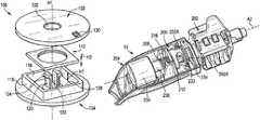
- FIG. 1is an exploded perspective view of a rotation stop device
- FIG. 2is another exploded perspective view of the device of FIG. 1 ;
- FIG. 3is a top view of the device of FIG. 1 ;
- FIG. 4is a perspective view of the device of FIG. 1 ;
- FIG. 5is a side view of the device of FIG. 1 ;
- FIG. 6is a bottom view of the device of FIG. 1 ;
- FIG. 7is a sectional perspective view of the device of FIG. 1 ;
- FIG. 8is an exploded perspective view of the device of FIG. 1 ;
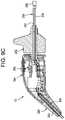
- FIG. 9Ais a side view of a surgical instrument that includes a rotation stop device
- FIG. 9Bis a perspective view of the instrument of FIG. 9A , shown with a handle cover removed for clarity;
- FIG. 9Cis a sectional side view of the instrument of FIG. 9A .
- Surgical instruments with rotation stop devices and related methodsare disclosed herein, e.g., for providing limited rotation between first and second components of the surgical instrument in a range greater than 360 degrees.
- Exemplary devicescan have a low profile and can include various features to facilitate packaging of the device within a larger instrument.
- FIGS. 1-8illustrate an exemplary rotation stop device 100 .
- the device 100can allow a first component 102 to rotate relative to a second component 104 about a rotation axis A 1 .
- the device 100can be configured to limit the degree to which the first component 102 is allowed to rotate relative to the second component 104 about the axis A 1 .
- the first component 102can be free to rotate relative to the second component 104 up to a predetermined limit.
- the limitcan be greater than 360 degrees.
- the limitcan be in the range of about 0 degrees to about 720 degrees.
- the limitcan be in the range of about 360 degrees to about 720 degrees.
- the limitcan be in the range of about 420 degrees to about 500 degrees.
- the limitcan be greater than 720 degrees.
- the limitcan be less than or equal to 360 degrees.
- the rotation stop device 100can be incorporated into a surgical instrument, such as an endoscope, arthroscope, surgical camera, or the like, to limit rotation between components of the surgical instrument
- the first component 102can include a threaded shaft 106 .
- the threaded shaft 106can extend along the rotation axis A 1 between a free end 108 and a supported end 110 .
- a nut 112can be mated to the shaft 106 .
- the nut 112can include an internally threaded opening 114 that is threaded onto the exterior thread of the shaft 106 . While a threaded engagement is shown, it will be appreciated that the nut 112 can be mated to the shaft 106 in other ways.
- the nutcan include a pin that projects into the opening of the nut. The pin can be received within a helical groove in the exterior surface of the shaft to mate the nut to the shaft.
- the second component 104can include features for preventing rotation of the nut 112 relative to the second component 104 about the axis A 1 , while allowing the nut to translate relative to the second component along the axis A 1 .
- the second component 104can include a cavity 116 configured to receive the nut 112 therein.
- the cavity 116can be defined by a sidewall 118 .
- At least a portion of the sidewall 118 and at least a portion of the nut 112can be planar or non-cylindrical and can be configured to bear against one another to prevent relative rotation between the nut and the second component 104 .
- the cavity 116can have a height H 1 that is greater than a height H 2 of the nut 112 , such that the nut is capable of traveling within the cavity along the axis A 1 .
- the threaded shaft 106can have a height H 3 that substantially matches or is slightly less than the height H 1 of the cavity 116 .
- the threaded shaft 106can have a height H 3 that is greater than the height H 2 of the nut 112 .
- the second component 104can include a pin protruding therefrom that is laterally offset from the rotation axis A 1 .
- the pincan be slidably received within a hole formed in the nut 112 .
- the second component 104can include one or more planar walls that contact corresponding planar outer surface portions of the nut 112 .
- the device 100can include features for retaining the first component 102 to the second component 104 , while allowing rotation therebetween.
- the second component 104can include one or more spring tabs 120 projecting therefrom.
- the spring tabs 120can be configured to snap-fit into a throughhole 122 formed in the first component 102 .
- Each spring tab 120can include a detent 124 that engages a groove or surface of the first component 102 to resist or prevent separation of the first component from the second component 104 , while allowing the first component to rotate relative to the second component.
- the first component 102can contact the upper surface of the sidewall 118 of the cavity 116 , thereby forming an enclosed space in which the nut 112 is non-rotatably captured.
- the first component 102 and the second component 104can be configured to remain at a fixed distance from one another along the axis A 1 as the first and second components are rotated through a range of permitted rotation. While spring tabs 120 are shown, it will be appreciated that various other retention features can be used instead or in addition. In some embodiments, retention features can be omitted and features of an instrument or system in which the device 100 is packaged can be relied upon to maintain the first and second components 102 , 104 at a fixed distance along the axis A 1 .
- the device 100can be assembled by threading the nut 112 onto the shaft 106 of the first component 102 and then inserting the shaft and the nut into the cavity 116 of the second component 104 .
- the spring tabs 120 of the second component 104can pass through the throughhole 122 in the first component 102 and snap into place to lock the components together.
- the nut 112can interact with the first and second components 102 , 104 to limit relative rotation therebetween about the axis A 1 .
- the shaft 106can be advanced downwards within the nut 112 , causing the nut to travel upwards within the cavity 116 .
- Rotationcan continue until the nut 112 contacts an upper stop, e.g., the underside 126 of the first component 102 . Since the nut 112 is constrained from rotation relative to the second component 104 , further relative rotation between the first and second components in the first direction is prevented, thereby forming a first rotation limit.
- the shaft 106can be retracted upwards within the nut 112 , causing the nut to travel downwards within the cavity 116 .
- Rotationcan continue until the nut 112 contacts a lower stop, e.g., the upper side 128 of the second component 104 or a floor of the cavity 116 . Since the nut 112 is constrained from rotation relative to the second component 104 and the second component is retained to the first component 102 , further relative rotation between the first and second components in the second direction is prevented, thereby forming a second rotation limit.
- the device 100can limit relative rotation of the first and second components 102 , 104 about the axis A 1 to a range defined by the first and second rotation limits.
- the geometries of the various components of the device 100can be selected to achieve a desired range of permitted rotation.
- the height H 2 of the nut 112can be increased to reduce the range of permitted rotation or can be decreased to extend the range of permitted rotation.
- the height H 3 of the shaft 106can be increased to increase the range of permitted rotation or can be decreased to reduce the range of permitted rotation.
- Other parameterscan be adjusted instead or in addition, including the height of the sidewall 118 , the pitch and/or lead of the threads on the shaft 106 and the nut 112 , and so forth.
- the device 100can include a sensor 130 for detecting the degree of rotation between the first and second components 102 , 104 .
- the sensor 130 outputcan be received by a controller, processor, or circuit and used to control a system or instrument of which the device 100 is a component part.
- the detected degree of rotation of a surgical instrumentcan be used to inform a surgical navigation system or surgical robot as to the position or orientation of the instrument.
- the detected degree of rotation of a visualization or camera instrumentcan be used to adjust the display of images captured by the camera, e.g., by rotating or otherwise correcting the displayed image on a screen in accordance with the rotation detected by the sensor 130 .
- Exemplary sensors 130can include potentiometers, Hall effect sensors, optical encoders, and the like.
- the device 100can include a throughhole 122 formed therein.
- the throughhole 122can extend completely through the device 100 , e.g., through the first component 102 , through the shaft 106 , through the nut 112 , and through the second component 104 , or can extend only partially through the device.
- the throughhole 122can be coaxial with the rotation axis A 1 , can be offset therefrom, or can be obliquely angled relative thereto.
- the throughhole 122can receive the spring tabs 120 discussed above to mate the first component 102 to the second component 104 .
- the throughhole 122can receive at least a portion of another component of a system or instrument of which the device 100 is a component part.
- the throughhole 122can receive a knob or shaft of a potentiometer therein. This can allow the potentiometer to be positioned closer to the device 100 than would otherwise be possible, providing a reduced footprint and more efficient packaging of the device 100 within a larger system or instrument.
- the throughhole 122can also be used to allow connections between parts, to route wires or optical fibers, and so forth.
- the device 100can have a low-profile, which can facilitate packaging of the device within a larger instrument or system.
- the distance H 4 between stop surfaces 126 , 128 of the device 100can be made as small as possible.
- the distance H 4can be less than about 20 mm, less than about 10 mm, less than about 9 mm, less than about 7 mm, and/or less than about 5 mm.
- FIGS. 9A-9Cillustrate an exemplary instrument 10 that includes a rotation stop device 200 of the type described herein.
- the device 200can include any of the features of the device 100 described above.
- the instrument 10can be a surgical instrument, such as a surgical camera system, optical system, endoscope, arthroscope, or the like.
- the instrument 10can include a proximal handle 204 , which can include a housing, and a forward knob 202 .
- the knob 202can be rotatable relative to the handle housing 204 about an axis A 2 .
- Rotation of the knob 202 relative to the handle 204 about the axis A 2can be effective to rotate a distal shaft 238 of the instrument, e.g., to reposition a camera or end effector 240 within a surgical site.
- the rotation stop device 200can be configured to limit rotation between the knob 202 and the handle 204 .
- the knob 202can serve as the “first component” of the device 200 , including a threaded shaft 206 that extends along the axis A 2 .
- the knob 202can be a monolithic component including the shaft 206 or, as shown, the shaft can be a separate component 202 A attached to the main portion 202 B of the knob 202 .
- the handle 204can serve as the “second component” of the device 200 , including a cavity 216 in which a nut 212 is captured such that the nut can translate along the axis A 2 but is constrained from rotating relative to the housing about the axis A 2 .
- the handle 204 and the knob 202can be maintained at a fixed distance relative to one another along the axis A 2 , for example by engagement between a journal or protrusion 232 of the housing and a groove 234 of the knob.
- the shaft 206can be threaded into the constrained nut 212 to allow the device 200 to limit rotation as described above.
- the shaft 206can be coupled to or formed integrally with the shaft 236 of a potentiometer 230 . Accordingly, rotation of the knob 202 and, by extension, the shaft 206 , can be effective to rotate the potentiometer shaft 236 to change an electric potential across the potentiometer 230 .
- the electric potential, or changes thereto,can be sensed to determine the degree of rotation of the knob 202 relative to the handle 204 .
- the sensed degree of rotationcan be used to rotate or otherwise correct an electronic display of images captured by the camera system by an amount equal to, proportional to, commensurate with, or otherwise based on the sensed degree of rotation.
- the rotation stop device 200can be effective to limit rotation of the potentiometer shaft 236 at an angle greater than 360 degrees.
- the instrument 10can include one or more elongate members that cross a rotation plane defined between the knob 202 and the handle 204 .
- a first end of the elongate membercan be fixed to a portion of the instrument distal to the rotation plane and a second end of the elongate member can be fixed to a portion of the instrument proximal to the rotation plane.
- the instrument 10can include one or more optical fibers 242 and/or one or more electrical conductors or wires 244 that extend from a location proximal to the rotation plane (e.g., a proximal cable 246 of the instrument), across the rotation plane, and into a location distal to the rotation plane (e.g., a distal shaft 238 or camera assembly 240 of the instrument).
- the instrument 10can include an optical fiber 242 that directs light from a light source proximal to the handle 204 to a location adjacent a distal end of the shaft 238 .
- the instrument 10can include an electrical conductor 244 that communicates digital or analog signals encoding image data captured by an image sensor disposed at or near the distal end of the shaft 238 from the image sensor to a controller or processor proximal to the handle 204 .
- the rotation stop device 200can allow the knob 202 to rotate relative to the handle 204 while limiting the rotation to an amount less than that which could damage, break, or stress the fibers 242 or conductors 244 .
- the devices disclosed hereincan be constructed from any of a variety of known materials. Exemplary materials include those which are suitable for use in surgical applications, including metals such as stainless steel, titanium, nickel, cobalt-chromium, or alloys and combinations thereof, polymers such as PEEK, ceramics, carbon fiber, and so forth.
- the various components of the devices disclosed hereincan be rigid or flexible. One or more components or portions of the device can be formed from a radiopaque material to facilitate visualization under fluoroscopy and other imaging techniques, or from a radiolucent material so as not to interfere with visualization of other structures. Exemplary radiolucent materials include carbon fiber and high-strength polymers.
- the devices and methods disclosed hereincan be used in minimally-invasive surgery and/or open surgery. While the devices and methods disclosed herein are generally described in the context of surgery on a human patient, it will be appreciated that the methods and devices disclosed herein can be used in any type of surgery on a human or animal subject, in non-surgical applications, on non-living objects, and so forth.
Landscapes
- Health & Medical Sciences (AREA)
- Life Sciences & Earth Sciences (AREA)
- Surgery (AREA)
- Engineering & Computer Science (AREA)
- Veterinary Medicine (AREA)
- Public Health (AREA)
- General Health & Medical Sciences (AREA)
- Animal Behavior & Ethology (AREA)
- Nuclear Medicine, Radiotherapy & Molecular Imaging (AREA)
- Molecular Biology (AREA)
- Biomedical Technology (AREA)
- Heart & Thoracic Surgery (AREA)
- Medical Informatics (AREA)
- Pathology (AREA)
- Physics & Mathematics (AREA)
- Radiology & Medical Imaging (AREA)
- Optics & Photonics (AREA)
- Biophysics (AREA)
- General Engineering & Computer Science (AREA)
- General Physics & Mathematics (AREA)
- Automation & Control Theory (AREA)
- Oral & Maxillofacial Surgery (AREA)
- Ophthalmology & Optometry (AREA)
- Mechanical Engineering (AREA)
- Surgical Instruments (AREA)
- Endoscopes (AREA)
Abstract
Description
Claims (34)
Priority Applications (7)
| Application Number | Priority Date | Filing Date | Title |
|---|---|---|---|
| US15/946,016US11294414B2 (en) | 2018-04-05 | 2018-04-05 | Surgical instruments with rotation stop devices |
| JP2019066538AJP7463060B2 (en) | 2018-04-05 | 2019-03-29 | Surgical instruments having rotational stops and related methods |
| AU2019202233AAU2019202233B2 (en) | 2018-04-05 | 2019-04-01 | Surgical instruments with rotation stop devices and related methods |
| EP19167372.2AEP3560408B1 (en) | 2018-04-05 | 2019-04-04 | Surgical instruments with rotation stop devices |
| EP21197668.3AEP3944054B1 (en) | 2018-04-05 | 2019-04-04 | Surgical instruments with rotation stop devices and related methods |
| CN201910271119.5ACN110338855B (en) | 2018-04-05 | 2019-04-04 | Surgical instrument with rotation stop device and related methods |
| US17/695,407US11832788B2 (en) | 2018-04-05 | 2022-03-15 | Surgical instruments with rotation stop devices and related methods |
Applications Claiming Priority (1)
| Application Number | Priority Date | Filing Date | Title |
|---|---|---|---|
| US15/946,016US11294414B2 (en) | 2018-04-05 | 2018-04-05 | Surgical instruments with rotation stop devices |
Related Child Applications (1)
| Application Number | Title | Priority Date | Filing Date |
|---|---|---|---|
| US17/695,407DivisionUS11832788B2 (en) | 2018-04-05 | 2022-03-15 | Surgical instruments with rotation stop devices and related methods |
Publications (2)
| Publication Number | Publication Date |
|---|---|
| US20190310681A1 US20190310681A1 (en) | 2019-10-10 |
| US11294414B2true US11294414B2 (en) | 2022-04-05 |
Family
ID=66092225
Family Applications (2)
| Application Number | Title | Priority Date | Filing Date |
|---|---|---|---|
| US15/946,016Active2039-12-11US11294414B2 (en) | 2018-04-05 | 2018-04-05 | Surgical instruments with rotation stop devices |
| US17/695,407ActiveUS11832788B2 (en) | 2018-04-05 | 2022-03-15 | Surgical instruments with rotation stop devices and related methods |
Family Applications After (1)
| Application Number | Title | Priority Date | Filing Date |
|---|---|---|---|
| US17/695,407ActiveUS11832788B2 (en) | 2018-04-05 | 2022-03-15 | Surgical instruments with rotation stop devices and related methods |
Country Status (5)
| Country | Link |
|---|---|
| US (2) | US11294414B2 (en) |
| EP (2) | EP3560408B1 (en) |
| JP (1) | JP7463060B2 (en) |
| CN (1) | CN110338855B (en) |
| AU (1) | AU2019202233B2 (en) |
Cited By (1)
| Publication number | Priority date | Publication date | Assignee | Title |
|---|---|---|---|---|
| US11832788B2 (en) | 2018-04-05 | 2023-12-05 | Medos International Sarl | Surgical instruments with rotation stop devices and related methods |
Families Citing this family (5)
| Publication number | Priority date | Publication date | Assignee | Title |
|---|---|---|---|---|
| US11832786B2 (en)* | 2020-01-16 | 2023-12-05 | Meditrina, Inc. | Endoscopic imaging and control systems and methods for use in diagnostic and therapeutic medical procedures |
| JP7303775B2 (en)* | 2020-04-09 | 2023-07-05 | 川崎重工業株式会社 | SURGERY ASSIST ROBOT AND SURGERY ASSIST ROBOT POSITIONING METHOD |
| WO2021241634A1 (en) | 2020-05-26 | 2021-12-02 | キヤノンメディカルシステムズ株式会社 | Ultrasonic diagnostic apparatus and image processing apparatus |
| US12120716B1 (en)* | 2020-06-26 | 2024-10-15 | Resonant Sciences, LLC | Initiating wideband simultaneous transmit and receive communications |
| US12287359B1 (en) | 2021-11-18 | 2025-04-29 | Resonant Sciences, LLC | Using near-field testing to determine how a radome affects the RF characteristics of an antenna |
Citations (40)
| Publication number | Priority date | Publication date | Assignee | Title |
|---|---|---|---|---|
| US2620911A (en) | 1950-06-27 | 1952-12-09 | Arma Corp | Limit stop |
| US2631709A (en) | 1949-05-02 | 1953-03-17 | Boeing Co | Limit stop mechanism |
| US3015793A (en) | 1960-04-19 | 1962-01-02 | Technology Instr Corp Of Acton | Wide angle mechanical stop for rotatable shafts in potentiometers and the like |
| US3037397A (en) | 1961-11-13 | 1962-06-05 | Reeves Instrument Corp | Adjustable limit stop |
| US3069914A (en) | 1960-12-23 | 1962-12-25 | Clarence R Laubenfels | Turn-limiting mechanism |
| US3203262A (en) | 1964-04-20 | 1965-08-31 | Gen Precision Inc | Limited multiple turn rotary mechanism |
| US3262535A (en) | 1964-09-25 | 1966-07-26 | Pasqua Thomas D De | Adjustable screw type limit stop |
| US3293925A (en)* | 1965-01-29 | 1966-12-27 | Gen Precision Inc | Multi-turn stop mechanism |
| US3762227A (en)* | 1971-10-12 | 1973-10-02 | Gen Motors Corp | Damped and cushioned stop |
| US4064981A (en) | 1975-02-24 | 1977-12-27 | The Garrett Corporation | Limit stop |
| EP0165727A1 (en) | 1984-05-30 | 1985-12-27 | Advanced Cardiovascular Systems, Inc. | Catheter rotary assembly |
| US4760907A (en)* | 1986-09-29 | 1988-08-02 | Sundstrand Corporation | Variable lead differential travel limiting mechanism |
| US5185004A (en)* | 1991-06-03 | 1993-02-09 | Danforth Biomedical, Inc. | Turn-limiting proximal adaptor for steerable catheter systems |
| US5255882A (en)* | 1990-06-19 | 1993-10-26 | Diehl Gmbh & Co. | Setting device with a nut controllable by a spindle |
| US5383876A (en)* | 1992-11-13 | 1995-01-24 | American Cardiac Ablation Co., Inc. | Fluid cooled electrosurgical probe for cutting and cauterizing tissue |
| US5479929A (en) | 1994-06-27 | 1996-01-02 | Acuson Corporation | Drive system with a multiturn rotary stop |
| US5673593A (en)* | 1995-12-14 | 1997-10-07 | Joerns Healthcare, Inc. | Overrunning nut for linear actuator |
| US5784435A (en) | 1997-04-23 | 1998-07-21 | General Electric Company | X-ray tube support column on a mobile x-ray product with improved rotational flexibility |
| US20050182409A1 (en)* | 2003-05-02 | 2005-08-18 | Ronald Callahan | Systems and methods accommodating relative motion in spine stabilization |
| US20090087252A1 (en) | 2007-09-14 | 2009-04-02 | Daniel Kolster | Device for limiting the angle of rotation of an object mounted in rotatable manner and optical observation apparatus |
| US20100249497A1 (en) | 2009-03-30 | 2010-09-30 | Peine William J | Surgical instrument |
| US20110144576A1 (en) | 2009-12-14 | 2011-06-16 | Voyage Medical, Inc. | Catheter orientation control system mechanisms |
| US20120238819A1 (en)* | 2009-12-02 | 2012-09-20 | Long Gang | Endoscope |
| US8808284B2 (en)* | 2008-09-26 | 2014-08-19 | Relievant Medsystems, Inc. | Systems for navigating an instrument through bone |
| US9155565B2 (en)* | 2004-03-31 | 2015-10-13 | Medos International Sarl | Adjustable-angle spinal fixation element |
| US20160327200A1 (en) | 2014-01-06 | 2016-11-10 | Philips Lighting Holding B.V. | Stop mechanism for a rotary device |
| US9561045B2 (en) | 2006-06-13 | 2017-02-07 | Intuitive Surgical Operations, Inc. | Tool with rotation lock |
| WO2017040692A1 (en) | 2015-09-01 | 2017-03-09 | Deka Products Limited Partnership | Endoscope with pannable camera and related method |
| WO2017095770A1 (en) | 2015-12-04 | 2017-06-08 | Ethicon Endo-Surgery, Llc | Devices and methods for increasing rotational torque during end effector articulation |
| US20170172386A1 (en)* | 2015-01-09 | 2017-06-22 | Olympus Corporation | Endoscope operation mechanism and endoscope |
| US20170231474A1 (en)* | 2016-02-11 | 2017-08-17 | Arrinex, Inc. | Method and device for image guided post-nasal nerve ablation |
| US9775627B2 (en)* | 2012-11-05 | 2017-10-03 | Relievant Medsystems, Inc. | Systems and methods for creating curved paths through bone and modulating nerves within the bone |
| US20170325671A1 (en)* | 2016-05-13 | 2017-11-16 | Karl Storz Endovision, Inc. | Optical instrument and articulating image sensing apparatus therefor |
| US20180161047A1 (en)* | 2016-12-09 | 2018-06-14 | Dfine, Inc. | Medical devices for treating hard tissues and related methods |
| US20190125320A1 (en)* | 2017-10-30 | 2019-05-02 | Ethicon Llc | Control system arrangements for a modular surgical instrument |
| US20190208143A1 (en)* | 2018-01-03 | 2019-07-04 | Xenocor, Inc. | Angled borescopes with digital image orientation |
| US10446058B2 (en)* | 2016-05-24 | 2019-10-15 | Blind Instruments, LLC | Tactile pin actuator |
| US10588691B2 (en)* | 2012-09-12 | 2020-03-17 | Relievant Medsystems, Inc. | Radiofrequency ablation of tissue within a vertebral body |
| US10610269B2 (en)* | 2017-09-05 | 2020-04-07 | Medos International Sarl | Modular surgical instruments and related methods |
| US20200205722A1 (en)* | 2011-01-25 | 2020-07-02 | Boston Scientific Scimed, Inc. | Systems and methods for maintaining a narrow body lumen |
Family Cites Families (9)
| Publication number | Priority date | Publication date | Assignee | Title |
|---|---|---|---|---|
| CA2050868C (en)* | 1990-10-05 | 2002-01-01 | Ernie Aranyi | Endoscopic surgical instrument |
| US5327905A (en)* | 1992-02-14 | 1994-07-12 | Boaz Avitall | Biplanar deflectable catheter for arrhythmogenic tissue ablation |
| JP3504681B2 (en)* | 1993-03-19 | 2004-03-08 | オリンパス株式会社 | Electronic endoscope device |
| DE60142587D1 (en)* | 2001-04-06 | 2010-08-26 | Covidien Ag | Blood vessel sealing and separating device |
| AU2005203521B2 (en)* | 2004-09-28 | 2011-11-17 | Ethicon Endo-Surgery | Applier having automated release of surgical device |
| US10548478B2 (en)* | 2010-07-01 | 2020-02-04 | Avinger, Inc. | Balloon atherectomy catheters with imaging |
| JP6375309B2 (en)* | 2013-02-01 | 2018-08-15 | デカ・プロダクツ・リミテッド・パートナーシップ | Endoscope with camera capable of panning |
| EP3399899B1 (en)* | 2016-01-05 | 2021-03-31 | Uroviu Corp. | Handheld endoscope |
| US11294414B2 (en) | 2018-04-05 | 2022-04-05 | Medos International Sàrl | Surgical instruments with rotation stop devices |
- 2018
- 2018-04-05USUS15/946,016patent/US11294414B2/enactiveActive
- 2019
- 2019-03-29JPJP2019066538Apatent/JP7463060B2/enactiveActive
- 2019-04-01AUAU2019202233Apatent/AU2019202233B2/enactiveActive
- 2019-04-04EPEP19167372.2Apatent/EP3560408B1/enactiveActive
- 2019-04-04EPEP21197668.3Apatent/EP3944054B1/enactiveActive
- 2019-04-04CNCN201910271119.5Apatent/CN110338855B/enactiveActive
- 2022
- 2022-03-15USUS17/695,407patent/US11832788B2/enactiveActive
Patent Citations (41)
| Publication number | Priority date | Publication date | Assignee | Title |
|---|---|---|---|---|
| US2631709A (en) | 1949-05-02 | 1953-03-17 | Boeing Co | Limit stop mechanism |
| US2620911A (en) | 1950-06-27 | 1952-12-09 | Arma Corp | Limit stop |
| US3015793A (en) | 1960-04-19 | 1962-01-02 | Technology Instr Corp Of Acton | Wide angle mechanical stop for rotatable shafts in potentiometers and the like |
| US3069914A (en) | 1960-12-23 | 1962-12-25 | Clarence R Laubenfels | Turn-limiting mechanism |
| US3037397A (en) | 1961-11-13 | 1962-06-05 | Reeves Instrument Corp | Adjustable limit stop |
| US3203262A (en) | 1964-04-20 | 1965-08-31 | Gen Precision Inc | Limited multiple turn rotary mechanism |
| US3262535A (en) | 1964-09-25 | 1966-07-26 | Pasqua Thomas D De | Adjustable screw type limit stop |
| US3293925A (en)* | 1965-01-29 | 1966-12-27 | Gen Precision Inc | Multi-turn stop mechanism |
| US3762227A (en)* | 1971-10-12 | 1973-10-02 | Gen Motors Corp | Damped and cushioned stop |
| US4064981A (en) | 1975-02-24 | 1977-12-27 | The Garrett Corporation | Limit stop |
| EP0165727A1 (en) | 1984-05-30 | 1985-12-27 | Advanced Cardiovascular Systems, Inc. | Catheter rotary assembly |
| US4760907A (en)* | 1986-09-29 | 1988-08-02 | Sundstrand Corporation | Variable lead differential travel limiting mechanism |
| US5255882A (en)* | 1990-06-19 | 1993-10-26 | Diehl Gmbh & Co. | Setting device with a nut controllable by a spindle |
| US5185004A (en)* | 1991-06-03 | 1993-02-09 | Danforth Biomedical, Inc. | Turn-limiting proximal adaptor for steerable catheter systems |
| US5383876A (en)* | 1992-11-13 | 1995-01-24 | American Cardiac Ablation Co., Inc. | Fluid cooled electrosurgical probe for cutting and cauterizing tissue |
| US5479929A (en) | 1994-06-27 | 1996-01-02 | Acuson Corporation | Drive system with a multiturn rotary stop |
| US5673593A (en)* | 1995-12-14 | 1997-10-07 | Joerns Healthcare, Inc. | Overrunning nut for linear actuator |
| US5784435A (en) | 1997-04-23 | 1998-07-21 | General Electric Company | X-ray tube support column on a mobile x-ray product with improved rotational flexibility |
| US20050182409A1 (en)* | 2003-05-02 | 2005-08-18 | Ronald Callahan | Systems and methods accommodating relative motion in spine stabilization |
| US9155565B2 (en)* | 2004-03-31 | 2015-10-13 | Medos International Sarl | Adjustable-angle spinal fixation element |
| US9561045B2 (en) | 2006-06-13 | 2017-02-07 | Intuitive Surgical Operations, Inc. | Tool with rotation lock |
| US20090087252A1 (en) | 2007-09-14 | 2009-04-02 | Daniel Kolster | Device for limiting the angle of rotation of an object mounted in rotatable manner and optical observation apparatus |
| US8808284B2 (en)* | 2008-09-26 | 2014-08-19 | Relievant Medsystems, Inc. | Systems for navigating an instrument through bone |
| US20100249497A1 (en) | 2009-03-30 | 2010-09-30 | Peine William J | Surgical instrument |
| US20120238819A1 (en)* | 2009-12-02 | 2012-09-20 | Long Gang | Endoscope |
| US20110144576A1 (en) | 2009-12-14 | 2011-06-16 | Voyage Medical, Inc. | Catheter orientation control system mechanisms |
| US20200205722A1 (en)* | 2011-01-25 | 2020-07-02 | Boston Scientific Scimed, Inc. | Systems and methods for maintaining a narrow body lumen |
| US10588691B2 (en)* | 2012-09-12 | 2020-03-17 | Relievant Medsystems, Inc. | Radiofrequency ablation of tissue within a vertebral body |
| US9775627B2 (en)* | 2012-11-05 | 2017-10-03 | Relievant Medsystems, Inc. | Systems and methods for creating curved paths through bone and modulating nerves within the bone |
| US20160327200A1 (en) | 2014-01-06 | 2016-11-10 | Philips Lighting Holding B.V. | Stop mechanism for a rotary device |
| US20170172386A1 (en)* | 2015-01-09 | 2017-06-22 | Olympus Corporation | Endoscope operation mechanism and endoscope |
| WO2017040692A1 (en) | 2015-09-01 | 2017-03-09 | Deka Products Limited Partnership | Endoscope with pannable camera and related method |
| US10357269B2 (en)* | 2015-12-04 | 2019-07-23 | Ethicon Llc | Devices and methods for increasing rotational torque during end effector articulation |
| WO2017095770A1 (en) | 2015-12-04 | 2017-06-08 | Ethicon Endo-Surgery, Llc | Devices and methods for increasing rotational torque during end effector articulation |
| US20170231474A1 (en)* | 2016-02-11 | 2017-08-17 | Arrinex, Inc. | Method and device for image guided post-nasal nerve ablation |
| US20170325671A1 (en)* | 2016-05-13 | 2017-11-16 | Karl Storz Endovision, Inc. | Optical instrument and articulating image sensing apparatus therefor |
| US10446058B2 (en)* | 2016-05-24 | 2019-10-15 | Blind Instruments, LLC | Tactile pin actuator |
| US20180161047A1 (en)* | 2016-12-09 | 2018-06-14 | Dfine, Inc. | Medical devices for treating hard tissues and related methods |
| US10610269B2 (en)* | 2017-09-05 | 2020-04-07 | Medos International Sarl | Modular surgical instruments and related methods |
| US20190125320A1 (en)* | 2017-10-30 | 2019-05-02 | Ethicon Llc | Control system arrangements for a modular surgical instrument |
| US20190208143A1 (en)* | 2018-01-03 | 2019-07-04 | Xenocor, Inc. | Angled borescopes with digital image orientation |
Non-Patent Citations (2)
| Title |
|---|
| Extended European Search Report for Application No. 21197668.3, dated Dec. 7, 2021 (8 pages). |
| Partial Extended European Search Report for Application No. 19167273.2, dated Sep. 5, 2019 (12 pages). |
Cited By (1)
| Publication number | Priority date | Publication date | Assignee | Title |
|---|---|---|---|---|
| US11832788B2 (en) | 2018-04-05 | 2023-12-05 | Medos International Sarl | Surgical instruments with rotation stop devices and related methods |
Also Published As
| Publication number | Publication date |
|---|---|
| JP7463060B2 (en) | 2024-04-08 |
| CN110338855A (en) | 2019-10-18 |
| AU2019202233A1 (en) | 2019-10-24 |
| US11832788B2 (en) | 2023-12-05 |
| EP3560408A2 (en) | 2019-10-30 |
| US20190310681A1 (en) | 2019-10-10 |
| EP3560408B1 (en) | 2021-11-10 |
| JP2019181189A (en) | 2019-10-24 |
| EP3944054B1 (en) | 2024-01-17 |
| AU2019202233B2 (en) | 2024-07-11 |
| EP3944054A1 (en) | 2022-01-26 |
| EP3944054C0 (en) | 2024-01-17 |
| EP3560408A3 (en) | 2020-01-22 |
| CN110338855B (en) | 2024-05-03 |
| US20220206524A1 (en) | 2022-06-30 |
Similar Documents
| Publication | Publication Date | Title |
|---|---|---|
| US11832788B2 (en) | Surgical instruments with rotation stop devices and related methods | |
| US8211008B2 (en) | Video endoscope | |
| KR102795697B1 (en) | Endoscope having a rotatable camera and related methods | |
| US9325881B2 (en) | Imaging mechanism and endoscope apparatus | |
| JP5871217B2 (en) | Endoscope | |
| CN102573599B (en) | Medical system and control method | |
| US8287449B2 (en) | Endoscope device | |
| US8019473B2 (en) | Manipulator and method of controlling manipulator | |
| US10451409B2 (en) | Insertion system | |
| US10182701B2 (en) | Electronic endoscope system with rotation angle calculation of insertion portion | |
| KR20180041759A (en) | Endoscope with pannable camera and related method | |
| US8668637B2 (en) | Endoscopic image pickup device | |
| US20160331212A1 (en) | Endoscope | |
| US20220240754A1 (en) | Endoscope, bending operation mechanism for endoscope, and operation portion for endoscope | |
| US20210161371A1 (en) | Endoscope | |
| JP2007054511A (en) | Endoscope device and endoscope imaging device | |
| JP2017029225A (en) | Endoscope apparatus | |
| CN119423951B (en) | Actuator, electrocoagulation hook and surgical robot | |
| CN113329675B (en) | Endoscope with a lens | |
| US20140107414A1 (en) | Distal Tip Channel Ramp |
Legal Events
| Date | Code | Title | Description |
|---|---|---|---|
| FEPP | Fee payment procedure | Free format text:ENTITY STATUS SET TO UNDISCOUNTED (ORIGINAL EVENT CODE: BIG.); ENTITY STATUS OF PATENT OWNER: LARGE ENTITY | |
| AS | Assignment | Owner name:DEPUY SYNTHES PRODUCTS, INC., MASSACHUSETTS Free format text:ASSIGNMENT OF ASSIGNORS INTEREST;ASSIGNORS:SHAINWALD, MARK;MARKS, JACOB A;SIGNING DATES FROM 20180416 TO 20180417;REEL/FRAME:045592/0490 | |
| AS | Assignment | Owner name:MEDOS INTERNATIONAL SARL, SWITZERLAND Free format text:ASSIGNMENT OF ASSIGNORS INTEREST;ASSIGNOR:DEPUY SYNTHES PRODUCTS, INC.;REEL/FRAME:047547/0483 Effective date:20180522 | |
| STPP | Information on status: patent application and granting procedure in general | Free format text:NON FINAL ACTION MAILED | |
| STPP | Information on status: patent application and granting procedure in general | Free format text:FINAL REJECTION MAILED | |
| STPP | Information on status: patent application and granting procedure in general | Free format text:RESPONSE AFTER FINAL ACTION FORWARDED TO EXAMINER | |
| STPP | Information on status: patent application and granting procedure in general | Free format text:ADVISORY ACTION MAILED | |
| STPP | Information on status: patent application and granting procedure in general | Free format text:DOCKETED NEW CASE - READY FOR EXAMINATION | |
| STPP | Information on status: patent application and granting procedure in general | Free format text:NON FINAL ACTION MAILED | |
| STPP | Information on status: patent application and granting procedure in general | Free format text:RESPONSE TO NON-FINAL OFFICE ACTION ENTERED AND FORWARDED TO EXAMINER | |
| STPP | Information on status: patent application and granting procedure in general | Free format text:NOTICE OF ALLOWANCE MAILED -- APPLICATION RECEIVED IN OFFICE OF PUBLICATIONS | |
| STPP | Information on status: patent application and granting procedure in general | Free format text:PUBLICATIONS -- ISSUE FEE PAYMENT VERIFIED | |
| STCF | Information on status: patent grant | Free format text:PATENTED CASE | |
| MAFP | Maintenance fee payment | Free format text:PAYMENT OF MAINTENANCE FEE, 4TH YEAR, LARGE ENTITY (ORIGINAL EVENT CODE: M1551); ENTITY STATUS OF PATENT OWNER: LARGE ENTITY Year of fee payment:4 |