US11293563B2 - Control valve - Google Patents
Control valveDownload PDFInfo
- Publication number
- US11293563B2 US11293563B2US16/108,740US201816108740AUS11293563B2US 11293563 B2US11293563 B2US 11293563B2US 201816108740 AUS201816108740 AUS 201816108740AUS 11293563 B2US11293563 B2US 11293563B2
- Authority
- US
- United States
- Prior art keywords
- annular spring
- lifting rod
- control valve
- contact
- annular
- Prior art date
- Legal status (The legal status is an assumption and is not a legal conclusion. Google has not performed a legal analysis and makes no representation as to the accuracy of the status listed.)
- Active, expires
Links
Images


Classifications
- F—MECHANICAL ENGINEERING; LIGHTING; HEATING; WEAPONS; BLASTING
- F16—ENGINEERING ELEMENTS AND UNITS; GENERAL MEASURES FOR PRODUCING AND MAINTAINING EFFECTIVE FUNCTIONING OF MACHINES OR INSTALLATIONS; THERMAL INSULATION IN GENERAL
- F16K—VALVES; TAPS; COCKS; ACTUATING-FLOATS; DEVICES FOR VENTING OR AERATING
- F16K41/00—Spindle sealings
- F16K41/02—Spindle sealings with stuffing-box ; Sealing rings
- F—MECHANICAL ENGINEERING; LIGHTING; HEATING; WEAPONS; BLASTING
- F16—ENGINEERING ELEMENTS AND UNITS; GENERAL MEASURES FOR PRODUCING AND MAINTAINING EFFECTIVE FUNCTIONING OF MACHINES OR INSTALLATIONS; THERMAL INSULATION IN GENERAL
- F16J—PISTONS; CYLINDERS; SEALINGS
- F16J15/00—Sealings
- F16J15/16—Sealings between relatively-moving surfaces
- F16J15/18—Sealings between relatively-moving surfaces with stuffing-boxes for elastic or plastic packings
- F16J15/184—Tightening mechanisms
- F—MECHANICAL ENGINEERING; LIGHTING; HEATING; WEAPONS; BLASTING
- F16—ENGINEERING ELEMENTS AND UNITS; GENERAL MEASURES FOR PRODUCING AND MAINTAINING EFFECTIVE FUNCTIONING OF MACHINES OR INSTALLATIONS; THERMAL INSULATION IN GENERAL
- F16K—VALVES; TAPS; COCKS; ACTUATING-FLOATS; DEVICES FOR VENTING OR AERATING
- F16K1/00—Lift valves or globe valves, i.e. cut-off apparatus with closure members having at least a component of their opening and closing motion perpendicular to the closing faces
- F16K1/32—Details
- F16K1/34—Cutting-off parts, e.g. valve members, seats
- F—MECHANICAL ENGINEERING; LIGHTING; HEATING; WEAPONS; BLASTING
- F16—ENGINEERING ELEMENTS AND UNITS; GENERAL MEASURES FOR PRODUCING AND MAINTAINING EFFECTIVE FUNCTIONING OF MACHINES OR INSTALLATIONS; THERMAL INSULATION IN GENERAL
- F16K—VALVES; TAPS; COCKS; ACTUATING-FLOATS; DEVICES FOR VENTING OR AERATING
- F16K31/00—Actuating devices; Operating means; Releasing devices
- F16K31/12—Actuating devices; Operating means; Releasing devices actuated by fluid
- F16K31/126—Actuating devices; Operating means; Releasing devices actuated by fluid the fluid acting on a diaphragm, bellows, or the like
- F16K31/1262—Actuating devices; Operating means; Releasing devices actuated by fluid the fluid acting on a diaphragm, bellows, or the like one side of the diaphragm being spring loaded
- F—MECHANICAL ENGINEERING; LIGHTING; HEATING; WEAPONS; BLASTING
- F16—ENGINEERING ELEMENTS AND UNITS; GENERAL MEASURES FOR PRODUCING AND MAINTAINING EFFECTIVE FUNCTIONING OF MACHINES OR INSTALLATIONS; THERMAL INSULATION IN GENERAL
- F16K—VALVES; TAPS; COCKS; ACTUATING-FLOATS; DEVICES FOR VENTING OR AERATING
- F16K37/00—Special means in or on valves or other cut-off apparatus for indicating or recording operation thereof, or for enabling an alarm to be given
- F16K37/0025—Electrical or magnetic means
- F16K37/0041—Electrical or magnetic means for measuring valve parameters
- H—ELECTRICITY
- H05—ELECTRIC TECHNIQUES NOT OTHERWISE PROVIDED FOR
- H05F—STATIC ELECTRICITY; NATURALLY-OCCURRING ELECTRICITY
- H05F3/00—Carrying-off electrostatic charges
- H05F3/02—Carrying-off electrostatic charges by means of earthing connections
Definitions
- the inventionrelates to a control valve for adjusting a process fluid flow in a process plant, comprising a valve housing having a valve seat, a lifting rod mounted on the valve housing and bearing a valve member which cooperates with the valve seat for opening and closing the control valve.
- FP 0 096 366 A2relates to an electrostatic draining device for cocks with a spherical surface having a contact element between a ball valve and a spindle, and a second contact element between the spindle and a stuffing box or a nut, wherein at least the contact element between the ball and the spindle consists of two metal pins that are guided in a bushing and are pressed into contact with the ball and with the spindle by means of a spring arranged between the two metal pins so that the spring is not exposed to aggressive fluids.
- This arrangement for draining electrostatic energyis not suitable for the above mentioned control valves, it is of a complex design and prone to a certain amount of abrasion.
- annular springsare disposed in grooves that contact a non-contoured counterpart. Because the spring tension is directed toward the groove, the spring will be urged into the groove, thus ensuring that it is securely held in the groove. The pressing forces ensure contact over a large area so that a high power can be transmitted safely.
- the control valve according to the inventionis characterized in that, for electrically contacting the lifting rod, a stationary contact holder is mounted opposite the lifting rod.
- the lifting rodperforms an axial movement relative to the contact holder which is fixed to the valve housing.
- the contact holderholds an electrically conductive annular coil that is axially movably mounted in the contact holder, with the annular spring extending around the lifting rod.
- the lifting rodserves to improve electrical contact between the lifting rod of the positioner and the valve housing.
- the annular springis capable of moving to such an extent in the axial direction, both relative to the lifting rod and within an axial limit of the contact holder, that the annular spring can roll along the lifting rod in the contact holder.
- the preload of the annular springis selected so that it is pressed against the lifting rod, which is in particular non-contoured, whereby friction with the lifting rod sets the annular spring in a rolling motion if its axial movement is limited by the contacting device and the lifting rod moves beyond this range.
- the contact holdercomprises a contact surface above the annular spring and/or a contact surface of a support part below the annular spring.
- the annular springis axially limited on both sides by the upper contact surface and/or the lower contact surface. Depending on the direction of movement of the valve rod, the annular spring thus contacts the upper contact surface or the lower contact surface. This allows the annular spring to be in electrical contact with the lifting rod, on the one hand, and with the housing, on the other hand. This is a simple way of creating a galvanic connection from the valve housing to the lifting rod, thus preventing electrostatic charging between the parts.
- the distance between the contact surface above the annular spring and the surface of the support part below the annular springis larger than the cross-section of the annular spring so that, to a small extent, the annular spring can move freely in the contact holder and can move along with the lifting rod.
- Another advantageous embodiment of the inventionis characterized in that the upper contact surface is designed in the form of an annular groove of a clamping ring, The latter can be screwed into the valve housing.
- Thishas the advantage that the annular groove for the annular spring can readily be provided in the clamping ring that is used anyway for mounting a stuffing box packing in the valve housing, which simplifies manufacture.
- Another advantageous embodiment of the inventionis characterized in that the lower support part is arranged between the annular spring and a stuffing box packing which latter is disposed between the lifting nod and the valve housing. Because the stuffing box packing is provided in a blind hole in the valve housing anyway, this allows the support part to be accommodated without any additional construction effort.
- Yet another advantageous embodiment of the inventionis characterized in that the support part is formed by an electrically conducting annular member that is in electrical contact with the valve housing so that a conductive path is formed from the annular spring to the housing via the support part and the clamping ring.
- the upper support surfacecomprises an annular spring element, said annular spring abutting the upper support surface, and that the upper contact surface is preloaded towards the annular spring.
- annular springis twisted in itself over its length so that the annular spring is permanently supported both on the upper contact surface of the valve housing and on the lower support part. Because of the twisted design of the annular spring, the various sections of the annular spring do not extend in one plane but what results is some kind of wave shape, thus ensuring that the annular spring is securely supported permanently both on the contact surface and on the support part, irrespective of the operating state of the lifting rod.
- annular springis located in an annular groove in the clamping ring, which groove runs at an angle to a plane that is perpendicular to a longitudinal axis of the valve stem, so that the annular spring is permanently supported both on the upper contact surface of the valve housing and on a surface of the lower support part.
- the beveled design of the annular groovealso advantageously ensures that the annular spring is permanently supported both on the contact surface and on the support part, independent of the actuation state of the lifting rod.
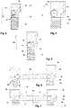
- FIG. 1is a lateral view of a control valve according to the invention
- FIG. 2is a detail view of the section of the inventive control valve which has the stuffing box packing for mounting the lifting rod;
- FIG. 3is a first detail view of a section of an annular spring in the control valve according to the invention.
- FIG. 4is a second detail view of the section of the annular spring in the control valve according to the invention.
- FIG. 5is a third detail view of the section of the annular spring in the control valve according to the invention.
- FIG. 6is a first lateral view of the section of the annular spring in the control valve according to the invention.
- FIG. 7is a second lateral view of the section of the annular spring in the control valve according to the invention.
- the control valve 2 illustrated in the drawingscomprises an actuating drive 4 and a valve housing 8 connected to the actuating drive 4 via a yoke 6 and having an inlet 10 and an outlet 12 and a valve opening 14 which can be closed or opened by means of a valve member 16 , which is actuated by means of a lifting rod 18 connected to the valve member 16 and the actuating drive 4 .
- the lifting rod 18is connected to a diaphragm working member 20 of the actuating drive 4 .
- the control valveis completed by a positioner 22 .
- the lifting rod 18is mounted on the valve housing 8 via a stuffing box packing 24 and it is mounted on the actuating drive 4 via another bearing 26 ( FIG. 1 ).
- the stuffing box packing 24is arranged in a blind hole 28 of the valve housing 8 and is held by a clamping ring 30 which is screwed into the valve housing 8 via a threaded connection 32 .
- a flange of the clamping ring 30has an annular shoulder 34 that extends over the yoke 6 .
- a contact holder fixed opposite the lifting rod 18is provided for the electrical contacting of the lifting rod 18 so that, in operation, the lifting rod 18 performs an axial movement relative to the contact holder.
- the contact deviceholds, on both sides and in an electrically conductive manner, an annular spring 36 that is axially movably mounted in the contact holder.
- the contact holderis formed by the clamping ring 30 and an annular lower support part 38 .
- the annular spring 36is arranged between the clamping ring 30 and the stuffing box packing 24 where it engages around the lifting rod 18 under preload so that the annular spring 36 is held on the lifting rod 18 by the spring force, as will be explained in more detail with reference to FIGS. 3 to 5 .
- FIG. 3is a detail view of the section of the control valve 2 according to the invention with the annular spring 36 , which view shows that during a downward stroke (arrow A) of the lifting rod 18 , the annular spring 36 makes contact with the lifting rod 18 and a surface 37 of the annular lower support part 38 which is located between the stuffing box packing 24 and the annular spring 36 .
- FIG. 4is a detail view of the section of the control valve 2 according to the invention with the annular spring 36 , which view shows that during an upward stroke (arrow B) of the lifting rod 18 the annular spring 36 makes contact with the lifting rod 18 and with an annular upper contact surface 40 of the clamping ring 30 .
- FIG. 5is a third detail view of the section of the annular spring 36 in the control valve 2 according to the invention, which view shows that a thin annular spring element 42 is disposed between the annular spring 36 and the clamping ring 30 as an axial support so that the clamping ring 30 is in permanent contact with the annular spring 36 and the annular spring 36 is in permanent contact with the lifting rod 18 , irrespective of the direction of movement of the lifting rod 18 (double arrow A, B), while still allowing some slight axial movement of the annular spring 36 .
- FIG. 6is a first lateral view of the section of an annular spring 36 in the control valve 2 according to the invention in which the annular spring 36 is twisted in itself so that it takes an wave-like shape, at the same time ensuring that the annular spring 36 is permanently supported by an annular groove 44 of the clamping ring 30 and by the support part 38 .
- FIG. 7is a second lateral view of the section of an annular spring 36 in the control valve 2 according to the invention, in which case the annular spring 36 lies in an annular groove 46 in the clamping ring which extends at an angle to a plane that is perpendicular to a longitudinal axis of the valve stem so that the annular spring 36 is permanently supported both on the upper contact surface 40 of the valve housing 8 and on a surface 37 of the lower support part 38 .
- the annular spring 36 , the clamping ring 30 and the support part 38are made of a conductive material to keep the entire transition resistance between the lifting rod and the valve housing low.
- annular spring 36rails on the lifting rod during a stroke movement, there is hardly any friction between the lifting rod and the annular spring which in particular prolongs the service life of the annular spring 36 .
Landscapes
- Engineering & Computer Science (AREA)
- General Engineering & Computer Science (AREA)
- Mechanical Engineering (AREA)
- Lift Valve (AREA)
Abstract
Description
- 2 control valve
- 4 actuating drive
- 6 yoke
- 8 valve housing
- 10 inlet
- 12 outlet
- 14 valve seat
- 16 valve member
- 18 lifting rod
- 20 diaphragm working
- 22 positioner
- 24 stuffing box packing
- 26 bearing
- 28 blind hole
- 30 clamping ring
- 32 threaded connection
- 34 flange
- 36 annular spring
- 37 surface
- 38 support part
- 40 contact surface
- 42 spring element
- 44 annular groove
- 46 annular groove
Claims (8)
Applications Claiming Priority (2)
| Application Number | Priority Date | Filing Date | Title |
|---|---|---|---|
| DE202017105035.1 | 2017-08-22 | ||
| DE202017105035.1UDE202017105035U1 (en) | 2017-08-22 | 2017-08-22 | Control valve |
Publications (2)
| Publication Number | Publication Date |
|---|---|
| US20190137001A1 US20190137001A1 (en) | 2019-05-09 |
| US11293563B2true US11293563B2 (en) | 2022-04-05 |
Family
ID=63363937
Family Applications (1)
| Application Number | Title | Priority Date | Filing Date |
|---|---|---|---|
| US16/108,740Active2038-08-27US11293563B2 (en) | 2017-08-22 | 2018-08-22 | Control valve |
Country Status (4)
| Country | Link |
|---|---|
| US (1) | US11293563B2 (en) |
| EP (1) | EP3447351B1 (en) |
| CN (1) | CN209540053U (en) |
| DE (1) | DE202017105035U1 (en) |
Families Citing this family (3)
| Publication number | Priority date | Publication date | Assignee | Title |
|---|---|---|---|---|
| DE202017104079U1 (en)* | 2017-07-07 | 2017-08-21 | Samson Ag | Actuator for process valves |
| WO2022101011A1 (en)* | 2020-11-13 | 2022-05-19 | Asco Sas | Valve system for atex environment |
| CN113236803B (en)* | 2021-06-08 | 2022-12-13 | 杭州维赫控制仪表有限公司 | Antibiotic pneumatic adjustment trip valve |
Citations (26)
| Publication number | Priority date | Publication date | Assignee | Title |
|---|---|---|---|---|
| US730381A (en)* | 1903-01-03 | 1903-06-09 | Samuel John Maddox | Piston-rod packing. |
| GB186526A (en) | 1921-10-18 | 1922-10-05 | George Ellison | Improvements relating to electric switches and the like |
| DE2328995A1 (en) | 1972-06-12 | 1974-01-03 | Kitamura Valve Mfg Co Ltd | VALVE |
| EP0096366A2 (en) | 1982-06-04 | 1983-12-21 | CHEMAT GmbH Armaturen für Industrie- und Nuklearanlagen | Electrostatic draining device for cocks with a spherical surface |
| JPS5911230Y2 (en) | 1979-07-18 | 1984-04-06 | 北村バルブ製造株式会社 | Valve with antistatic device |
| US4474356A (en)* | 1982-05-07 | 1984-10-02 | Baumann Hans D | Control valve with integral streamlined seating means |
| US4640305A (en)* | 1984-11-14 | 1987-02-03 | White Consolidated Industries, Inc. | High temperature, zero leakage packing assembly |
| DE3722816A1 (en) | 1987-07-10 | 1989-01-19 | Richter Chemie Technik Gmbh | Retightening device for a stuffing box |
| EP0308390A1 (en) | 1987-09-16 | 1989-03-22 | Fisher Controls International, Inc. | Valve stem packing containment for high pressure, high temperature |
| JPH01169188A (en) | 1987-12-25 | 1989-07-04 | Hitachi Ltd | How to average the valve gland seal tightening pressure |
| US4890937A (en)* | 1988-09-14 | 1990-01-02 | Peter J. Balsells | Spring-loaded bearing |
| US4915366A (en)* | 1988-04-25 | 1990-04-10 | Peter J. Balsells | Outside back angle canted coil spring |
| JPH02122277U (en) | 1989-03-20 | 1990-10-05 | ||
| DE3925888A1 (en) | 1989-08-04 | 1991-02-14 | Chemat Gmbh | SHIFT SHAFT SEALING FOR FITTINGS |
| US5134244A (en)* | 1988-04-25 | 1992-07-28 | Peter J. Balsells | Electromagnetic shielding seal for rotary/reciprocating shaft |
| US5542682A (en)* | 1995-03-27 | 1996-08-06 | American Variseal | Slant coil spring and seal |
| US5791629A (en)* | 1996-10-31 | 1998-08-11 | Fisher Controls International, Inc. | Bushing-less stem guided control valve |
| DE19528127C2 (en) | 1995-08-01 | 2000-05-04 | Abb Patent Gmbh | Contacting device for cable connections |
| US6749358B2 (en)* | 2001-11-21 | 2004-06-15 | Bal Seal Engineering Co., Inc. | Connector for latching and carrying current capabilities with tooless connection |
| US20060096643A1 (en)* | 2004-11-10 | 2006-05-11 | Mccarty Michael W | Seal assembly for a fluid pressure control device |
| US20060127170A1 (en)* | 2003-02-18 | 2006-06-15 | Pete Balsells | Spring holding connectors |
| DE102006033209B3 (en) | 2006-07-13 | 2007-11-08 | Siemens Ag | Circuit breaker e.g. three-position circuit breaker, for use in gas-insulated switchgear, has three contact units, of which one contact unit is arranged between inner surface of one of three connections and outer surface of casing |
| DE102007031141B4 (en) | 2007-07-02 | 2009-02-19 | Siemens Ag | Method and device for producing a contact spring of a contact arrangement, in particular for electrical switches |
| US20100050786A1 (en) | 2008-09-04 | 2010-03-04 | Samson Ag | Method and device for testing the functionality of an actuator having a pneumatic drive |
| US9293849B2 (en)* | 2008-07-30 | 2016-03-22 | Bal Seal Engineering, Inc. | Electrical connector using a canted coil multi-metallic wire |
| DE102015016357A1 (en) | 2015-12-17 | 2017-06-22 | Samson Aktiengesellschaft | Control valve of a process plant, method for operating the control valve |
- 2017
- 2017-08-22DEDE202017105035.1Upatent/DE202017105035U1/enactiveActive
- 2018
- 2018-08-22CNCN201821359405.4Upatent/CN209540053U/enactiveActive
- 2018-08-22EPEP18190172.9Apatent/EP3447351B1/enactiveActive
- 2018-08-22USUS16/108,740patent/US11293563B2/enactiveActive
Patent Citations (27)
| Publication number | Priority date | Publication date | Assignee | Title |
|---|---|---|---|---|
| US730381A (en)* | 1903-01-03 | 1903-06-09 | Samuel John Maddox | Piston-rod packing. |
| GB186526A (en) | 1921-10-18 | 1922-10-05 | George Ellison | Improvements relating to electric switches and the like |
| DE2328995A1 (en) | 1972-06-12 | 1974-01-03 | Kitamura Valve Mfg Co Ltd | VALVE |
| JPS5911230Y2 (en) | 1979-07-18 | 1984-04-06 | 北村バルブ製造株式会社 | Valve with antistatic device |
| US4474356A (en)* | 1982-05-07 | 1984-10-02 | Baumann Hans D | Control valve with integral streamlined seating means |
| EP0096366A2 (en) | 1982-06-04 | 1983-12-21 | CHEMAT GmbH Armaturen für Industrie- und Nuklearanlagen | Electrostatic draining device for cocks with a spherical surface |
| US4640305A (en)* | 1984-11-14 | 1987-02-03 | White Consolidated Industries, Inc. | High temperature, zero leakage packing assembly |
| DE3722816A1 (en) | 1987-07-10 | 1989-01-19 | Richter Chemie Technik Gmbh | Retightening device for a stuffing box |
| EP0308390A1 (en) | 1987-09-16 | 1989-03-22 | Fisher Controls International, Inc. | Valve stem packing containment for high pressure, high temperature |
| US4886241A (en)* | 1987-09-16 | 1989-12-12 | Fisher Controls International, Inc. | Valve stem packing containment for high pressure, high temperature |
| JPH01169188A (en) | 1987-12-25 | 1989-07-04 | Hitachi Ltd | How to average the valve gland seal tightening pressure |
| US4915366A (en)* | 1988-04-25 | 1990-04-10 | Peter J. Balsells | Outside back angle canted coil spring |
| US5134244A (en)* | 1988-04-25 | 1992-07-28 | Peter J. Balsells | Electromagnetic shielding seal for rotary/reciprocating shaft |
| US4890937A (en)* | 1988-09-14 | 1990-01-02 | Peter J. Balsells | Spring-loaded bearing |
| JPH02122277U (en) | 1989-03-20 | 1990-10-05 | ||
| DE3925888A1 (en) | 1989-08-04 | 1991-02-14 | Chemat Gmbh | SHIFT SHAFT SEALING FOR FITTINGS |
| US5542682A (en)* | 1995-03-27 | 1996-08-06 | American Variseal | Slant coil spring and seal |
| DE19528127C2 (en) | 1995-08-01 | 2000-05-04 | Abb Patent Gmbh | Contacting device for cable connections |
| US5791629A (en)* | 1996-10-31 | 1998-08-11 | Fisher Controls International, Inc. | Bushing-less stem guided control valve |
| US6749358B2 (en)* | 2001-11-21 | 2004-06-15 | Bal Seal Engineering Co., Inc. | Connector for latching and carrying current capabilities with tooless connection |
| US20060127170A1 (en)* | 2003-02-18 | 2006-06-15 | Pete Balsells | Spring holding connectors |
| US20060096643A1 (en)* | 2004-11-10 | 2006-05-11 | Mccarty Michael W | Seal assembly for a fluid pressure control device |
| DE102006033209B3 (en) | 2006-07-13 | 2007-11-08 | Siemens Ag | Circuit breaker e.g. three-position circuit breaker, for use in gas-insulated switchgear, has three contact units, of which one contact unit is arranged between inner surface of one of three connections and outer surface of casing |
| DE102007031141B4 (en) | 2007-07-02 | 2009-02-19 | Siemens Ag | Method and device for producing a contact spring of a contact arrangement, in particular for electrical switches |
| US9293849B2 (en)* | 2008-07-30 | 2016-03-22 | Bal Seal Engineering, Inc. | Electrical connector using a canted coil multi-metallic wire |
| US20100050786A1 (en) | 2008-09-04 | 2010-03-04 | Samson Ag | Method and device for testing the functionality of an actuator having a pneumatic drive |
| DE102015016357A1 (en) | 2015-12-17 | 2017-06-22 | Samson Aktiengesellschaft | Control valve of a process plant, method for operating the control valve |
Non-Patent Citations (2)
| Title |
|---|
| European Search Repod dated Jan. 16, 2019, by the European Patent Office in corresponding European application EP 18 19 0172.9, 7 pages in German. |
| German Search Report dated Mar. 6, 2018, by the German Patent Office in corrsponding German application DE 20 2017 105 035.1, 5 pages in German. |
Also Published As
| Publication number | Publication date |
|---|---|
| EP3447351B1 (en) | 2020-09-23 |
| US20190137001A1 (en) | 2019-05-09 |
| EP3447351A1 (en) | 2019-02-27 |
| CN209540053U (en) | 2019-10-25 |
| DE202017105035U1 (en) | 2018-11-23 |
Similar Documents
| Publication | Publication Date | Title |
|---|---|---|
| US11293563B2 (en) | Control valve | |
| US3510814A (en) | Solenoid operator having armature provided with guide rings | |
| KR101626075B1 (en) | Valve apparatus | |
| US20110012041A1 (en) | Electromagnetic actuator for a proportional solenoid valve | |
| EP1659321A1 (en) | Solenoid operated valve assembly and method of making the same | |
| CN108700216A (en) | Electric valve | |
| CN110410574B (en) | Actuator Bushing with Integral Seal | |
| CN100554741C (en) | One-way valve | |
| US3439711A (en) | Sequentially power actuated plural valves | |
| US20150020901A1 (en) | Control valve with integral pressure switch | |
| US4577661A (en) | High speed-high flow spool valve | |
| US2975340A (en) | Oil bath solenoid | |
| EP3418847B1 (en) | Flow regulation valve | |
| KR20160046831A (en) | High cycle and speed valve | |
| CN109469758B (en) | Valve for controlling a fluid | |
| RU2659907C1 (en) | Electromagnetic valve | |
| EP3633252A1 (en) | Electromagnetic fluid valve | |
| EP0745797A1 (en) | Pivoting valve assembly | |
| CN107023684B (en) | Y-valve | |
| US2685427A (en) | Valve and valve seal therefor | |
| US3041037A (en) | Gate valve assembly | |
| JP2015082347A (en) | Circuit breaker, operation unit, and switchgear | |
| CN222963386U (en) | A high pressure straight-through valve | |
| EP4244509B1 (en) | Valve system for atex environment | |
| CN213900054U (en) | High stability flow control solenoid valve |
Legal Events
| Date | Code | Title | Description |
|---|---|---|---|
| FEPP | Fee payment procedure | Free format text:ENTITY STATUS SET TO UNDISCOUNTED (ORIGINAL EVENT CODE: BIG.); ENTITY STATUS OF PATENT OWNER: LARGE ENTITY | |
| STPP | Information on status: patent application and granting procedure in general | Free format text:DOCKETED NEW CASE - READY FOR EXAMINATION | |
| STPP | Information on status: patent application and granting procedure in general | Free format text:NON FINAL ACTION MAILED | |
| STPP | Information on status: patent application and granting procedure in general | Free format text:RESPONSE TO NON-FINAL OFFICE ACTION ENTERED AND FORWARDED TO EXAMINER | |
| STPP | Information on status: patent application and granting procedure in general | Free format text:FINAL REJECTION MAILED | |
| STPP | Information on status: patent application and granting procedure in general | Free format text:DOCKETED NEW CASE - READY FOR EXAMINATION | |
| STPP | Information on status: patent application and granting procedure in general | Free format text:NOTICE OF ALLOWANCE MAILED -- APPLICATION RECEIVED IN OFFICE OF PUBLICATIONS | |
| AS | Assignment | Owner name:SAMSON AG, GERMANY Free format text:ASSIGNMENT OF ASSIGNORS INTEREST;ASSIGNORS:KIRBS, UWE;VNUCEC, DOMAGOJ;REEL/FRAME:058230/0956 Effective date:20190121 | |
| STPP | Information on status: patent application and granting procedure in general | Free format text:PUBLICATIONS -- ISSUE FEE PAYMENT VERIFIED | |
| STCF | Information on status: patent grant | Free format text:PATENTED CASE | |
| MAFP | Maintenance fee payment | Free format text:PAYMENT OF MAINTENANCE FEE, 4TH YEAR, LARGE ENTITY (ORIGINAL EVENT CODE: M1551); ENTITY STATUS OF PATENT OWNER: LARGE ENTITY Year of fee payment:4 |