US11293309B2 - Active thrust management of a turbopump within a supercritical working fluid circuit in a heat engine system - Google Patents
Active thrust management of a turbopump within a supercritical working fluid circuit in a heat engine systemDownload PDFInfo
- Publication number
- US11293309B2 US11293309B2US16/800,420US202016800420AUS11293309B2US 11293309 B2US11293309 B2US 11293309B2US 202016800420 AUS202016800420 AUS 202016800420AUS 11293309 B2US11293309 B2US 11293309B2
- Authority
- US
- United States
- Prior art keywords
- bearing
- pressure
- turbopump
- working fluid
- turbine
- Prior art date
- Legal status (The legal status is an assumption and is not a legal conclusion. Google has not performed a legal analysis and makes no representation as to the accuracy of the status listed.)
- Active
Links
Images


Classifications
- F—MECHANICAL ENGINEERING; LIGHTING; HEATING; WEAPONS; BLASTING
- F01—MACHINES OR ENGINES IN GENERAL; ENGINE PLANTS IN GENERAL; STEAM ENGINES
- F01D—NON-POSITIVE DISPLACEMENT MACHINES OR ENGINES, e.g. STEAM TURBINES
- F01D25/00—Component parts, details, or accessories, not provided for in, or of interest apart from, other groups
- F01D25/18—Lubricating arrangements
- F01D25/22—Lubricating arrangements using working-fluid or other gaseous fluid as lubricant
- F—MECHANICAL ENGINEERING; LIGHTING; HEATING; WEAPONS; BLASTING
- F01—MACHINES OR ENGINES IN GENERAL; ENGINE PLANTS IN GENERAL; STEAM ENGINES
- F01K—STEAM ENGINE PLANTS; STEAM ACCUMULATORS; ENGINE PLANTS NOT OTHERWISE PROVIDED FOR; ENGINES USING SPECIAL WORKING FLUIDS OR CYCLES
- F01K7/00—Steam engine plants characterised by the use of specific types of engine; Plants or engines characterised by their use of special steam systems, cycles or processes; Control means specially adapted for such systems, cycles or processes; Use of withdrawn or exhaust steam for feed-water heating
- F01K7/32—Steam engine plants characterised by the use of specific types of engine; Plants or engines characterised by their use of special steam systems, cycles or processes; Control means specially adapted for such systems, cycles or processes; Use of withdrawn or exhaust steam for feed-water heating the engines using steam of critical or overcritical pressure
- F—MECHANICAL ENGINEERING; LIGHTING; HEATING; WEAPONS; BLASTING
- F01—MACHINES OR ENGINES IN GENERAL; ENGINE PLANTS IN GENERAL; STEAM ENGINES
- F01D—NON-POSITIVE DISPLACEMENT MACHINES OR ENGINES, e.g. STEAM TURBINES
- F01D15/00—Adaptations of machines or engines for special use; Combinations of engines with devices driven thereby
- F01D15/08—Adaptations for driving, or combinations with, pumps
- F—MECHANICAL ENGINEERING; LIGHTING; HEATING; WEAPONS; BLASTING
- F01—MACHINES OR ENGINES IN GENERAL; ENGINE PLANTS IN GENERAL; STEAM ENGINES
- F01D—NON-POSITIVE DISPLACEMENT MACHINES OR ENGINES, e.g. STEAM TURBINES
- F01D17/00—Regulating or controlling by varying flow
- F01D17/02—Arrangement of sensing elements
- F01D17/08—Arrangement of sensing elements responsive to condition of working-fluid, e.g. pressure
- F—MECHANICAL ENGINEERING; LIGHTING; HEATING; WEAPONS; BLASTING
- F01—MACHINES OR ENGINES IN GENERAL; ENGINE PLANTS IN GENERAL; STEAM ENGINES
- F01D—NON-POSITIVE DISPLACEMENT MACHINES OR ENGINES, e.g. STEAM TURBINES
- F01D25/00—Component parts, details, or accessories, not provided for in, or of interest apart from, other groups
- F01D25/08—Cooling; Heating; Heat-insulation
- F01D25/10—Heating, e.g. warming-up before starting
- F—MECHANICAL ENGINEERING; LIGHTING; HEATING; WEAPONS; BLASTING
- F01—MACHINES OR ENGINES IN GENERAL; ENGINE PLANTS IN GENERAL; STEAM ENGINES
- F01D—NON-POSITIVE DISPLACEMENT MACHINES OR ENGINES, e.g. STEAM TURBINES
- F01D25/00—Component parts, details, or accessories, not provided for in, or of interest apart from, other groups
- F01D25/16—Arrangement of bearings; Supporting or mounting bearings in casings
- F01D25/166—Sliding contact bearing
- F01D25/168—Sliding contact bearing for axial load mainly
- F—MECHANICAL ENGINEERING; LIGHTING; HEATING; WEAPONS; BLASTING
- F01—MACHINES OR ENGINES IN GENERAL; ENGINE PLANTS IN GENERAL; STEAM ENGINES
- F01D—NON-POSITIVE DISPLACEMENT MACHINES OR ENGINES, e.g. STEAM TURBINES
- F01D3/00—Machines or engines with axial-thrust balancing effected by working-fluid
- F01D3/04—Machines or engines with axial-thrust balancing effected by working-fluid axial thrust being compensated by thrust-balancing dummy piston or the like
- F—MECHANICAL ENGINEERING; LIGHTING; HEATING; WEAPONS; BLASTING
- F01—MACHINES OR ENGINES IN GENERAL; ENGINE PLANTS IN GENERAL; STEAM ENGINES
- F01K—STEAM ENGINE PLANTS; STEAM ACCUMULATORS; ENGINE PLANTS NOT OTHERWISE PROVIDED FOR; ENGINES USING SPECIAL WORKING FLUIDS OR CYCLES
- F01K11/00—Plants characterised by the engines being structurally combined with boilers or condensers
- F01K11/02—Plants characterised by the engines being structurally combined with boilers or condensers the engines being turbines
- F—MECHANICAL ENGINEERING; LIGHTING; HEATING; WEAPONS; BLASTING
- F01—MACHINES OR ENGINES IN GENERAL; ENGINE PLANTS IN GENERAL; STEAM ENGINES
- F01K—STEAM ENGINE PLANTS; STEAM ACCUMULATORS; ENGINE PLANTS NOT OTHERWISE PROVIDED FOR; ENGINES USING SPECIAL WORKING FLUIDS OR CYCLES
- F01K23/00—Plants characterised by more than one engine delivering power external to the plant, the engines being driven by different fluids
- F01K23/02—Plants characterised by more than one engine delivering power external to the plant, the engines being driven by different fluids the engine cycles being thermally coupled
- F—MECHANICAL ENGINEERING; LIGHTING; HEATING; WEAPONS; BLASTING
- F01—MACHINES OR ENGINES IN GENERAL; ENGINE PLANTS IN GENERAL; STEAM ENGINES
- F01K—STEAM ENGINE PLANTS; STEAM ACCUMULATORS; ENGINE PLANTS NOT OTHERWISE PROVIDED FOR; ENGINES USING SPECIAL WORKING FLUIDS OR CYCLES
- F01K25/00—Plants or engines characterised by use of special working fluids, not otherwise provided for; Plants operating in closed cycles and not otherwise provided for
- F01K25/08—Plants or engines characterised by use of special working fluids, not otherwise provided for; Plants operating in closed cycles and not otherwise provided for using special vapours
- F01K25/10—Plants or engines characterised by use of special working fluids, not otherwise provided for; Plants operating in closed cycles and not otherwise provided for using special vapours the vapours being cold, e.g. ammonia, carbon dioxide, ether
- F01K25/103—Carbon dioxide
- F—MECHANICAL ENGINEERING; LIGHTING; HEATING; WEAPONS; BLASTING
- F04—POSITIVE - DISPLACEMENT MACHINES FOR LIQUIDS; PUMPS FOR LIQUIDS OR ELASTIC FLUIDS
- F04D—NON-POSITIVE-DISPLACEMENT PUMPS
- F04D13/00—Pumping installations or systems
- F04D13/02—Units comprising pumps and their driving means
- F04D13/04—Units comprising pumps and their driving means the pump being fluid driven
- F—MECHANICAL ENGINEERING; LIGHTING; HEATING; WEAPONS; BLASTING
- F04—POSITIVE - DISPLACEMENT MACHINES FOR LIQUIDS; PUMPS FOR LIQUIDS OR ELASTIC FLUIDS
- F04D—NON-POSITIVE-DISPLACEMENT PUMPS
- F04D29/00—Details, component parts, or accessories
- F04D29/04—Shafts or bearings, or assemblies thereof
- F04D29/041—Axial thrust balancing
- F04D29/0413—Axial thrust balancing hydrostatic; hydrodynamic thrust bearings
- F—MECHANICAL ENGINEERING; LIGHTING; HEATING; WEAPONS; BLASTING
- F04—POSITIVE - DISPLACEMENT MACHINES FOR LIQUIDS; PUMPS FOR LIQUIDS OR ELASTIC FLUIDS
- F04D—NON-POSITIVE-DISPLACEMENT PUMPS
- F04D29/00—Details, component parts, or accessories
- F04D29/04—Shafts or bearings, or assemblies thereof
- F04D29/046—Bearings
- F04D29/047—Bearings hydrostatic; hydrodynamic
- F04D29/0473—Bearings hydrostatic; hydrodynamic for radial pumps
- F—MECHANICAL ENGINEERING; LIGHTING; HEATING; WEAPONS; BLASTING
- F04—POSITIVE - DISPLACEMENT MACHINES FOR LIQUIDS; PUMPS FOR LIQUIDS OR ELASTIC FLUIDS
- F04D—NON-POSITIVE-DISPLACEMENT PUMPS
- F04D29/00—Details, component parts, or accessories
- F04D29/06—Lubrication
- F04D29/061—Lubrication especially adapted for liquid pumps
- F—MECHANICAL ENGINEERING; LIGHTING; HEATING; WEAPONS; BLASTING
- F05—INDEXING SCHEMES RELATING TO ENGINES OR PUMPS IN VARIOUS SUBCLASSES OF CLASSES F01-F04
- F05D—INDEXING SCHEME FOR ASPECTS RELATING TO NON-POSITIVE-DISPLACEMENT MACHINES OR ENGINES, GAS-TURBINES OR JET-PROPULSION PLANTS
- F05D2240/00—Components
- F05D2240/50—Bearings
- F05D2240/52—Axial thrust bearings
- F—MECHANICAL ENGINEERING; LIGHTING; HEATING; WEAPONS; BLASTING
- F05—INDEXING SCHEMES RELATING TO ENGINES OR PUMPS IN VARIOUS SUBCLASSES OF CLASSES F01-F04
- F05D—INDEXING SCHEME FOR ASPECTS RELATING TO NON-POSITIVE-DISPLACEMENT MACHINES OR ENGINES, GAS-TURBINES OR JET-PROPULSION PLANTS
- F05D2260/00—Function
- F05D2260/98—Lubrication
Definitions
- Waste heatis often created as a byproduct of industrial processes where flowing streams of high-temperature liquids, gases, or fluids must be exhausted into the environment or removed in some way in an effort to maintain the operating temperatures of the industrial process equipment.
- Some industrial processesutilize heat exchanger devices to capture and recycle waste heat back into the process via other process streams.
- the capturing and recycling of waste heatis generally infeasible by industrial processes that utilize high temperatures or have insufficient mass flow or other unfavorable conditions.
- Waste heatcan be converted into useful energy by a variety of turbine generator or heat engine systems that employ thermodynamic methods, such as Rankine cycles.
- Rankine cycles and similar thermodynamic cyclesare typically steam-based processes that recover and utilize waste heat to generate steam for driving an expander, such as a turbine, connected to an electric generator, a pump, and/or another device.
- an organic Rankine cycleutilizes a lower boiling-point working fluid, instead of water.
- Exemplary lower boiling-point working fluidsinclude hydrocarbons, such as light hydrocarbons (e.g., propane or butane) and halogenated hydrocarbon, such as hydrochlorofluorocarbons (HCFCs) or hydrofluorocarbons (HFCs) (e.g., R245fa).
- hydrocarbonssuch as light hydrocarbons (e.g., propane or butane) and halogenated hydrocarbon, such as hydrochlorofluorocarbons (HCFCs) or hydrofluorocarbons (HFCs) (e.g., R245fa).
- HCFCshydrochlorofluorocarbons
- HFCshydrofluorocarbons
- a synchronous power generatoris a commonly employed turbine generator utilized for generating electrical energy in large scales (e.g., megawatt scale) throughout the world for both commercial and non-commercial use.
- the synchronous power generatorgenerally supplies electricity to an electrical bus or grid (e.g., an alternating current bus) that usually has a varying load or demand over time.
- an electrical bus or gride.g., an alternating current bus
- the frequency of the synchronous power generatormust be tuned and maintained to match the frequency of the electrical bus or grid. Severe damage may occur to the synchronous power generator as well as the electrical bus or grid should the frequency of the synchronous power generator become unsynchronized with the frequency of the electrical bus or grid.
- Turbine generator systemsalso may suffer an overspeed condition during the generation of electricity—generally—due to high electrical demands during peak usage times.
- Turbine generator systemsmay be damaged due to an increasing rotational speed of the moving parts, such as turbines, generators, and/or gears, as well as a deficit in lubricating and cooling such turbomachinery.
- the turbines and pumps utilized in turbine generator systemsare susceptible to fail due to thermal shock when exposed to substantial and imminent temperature differentials. Such rapid change of temperature generally occurs when the turbine or pump is exposed to a supercritical working fluid. The thermal shock may cause valves, blades, and other parts to crack and result in catastrophic damage to the unit.
- the control of the turbine driven pumpis quite relevant to the operation and efficiency of an advanced Rankine cycle process.
- the control of the turbopumpis often not precise enough to achieve the most efficient or maximum operating conditions without damaging the turbopump.
- the turbopumpgenerally requires proper lubrication and temperature regulation—often provided by a bearing or seal gas.
- the turbopump and/or turbomachinery components of the turbopumphave very close tolerances and may be susceptible to immediate damage if there is an interruption of the bearing seal gas. If too much or not enough pressure is applied to a thrust bearing of the turbopump, then the rotor of the turbopump is likely to rub against stationary parts, such that the turbopump damages itself and ceases to operate.
- Embodiments of the inventiongenerally provide a heat engine system, a turbopump system, and methods for lubricating a turbopump in the heat engine system while generating mechanical and electrical energy.
- the systems and methods described hereinprovide proper lubrication and cooling to turbomachinery components of a turbopump by controlling pressures applied to a thrust bearing in the turbopump.
- the applied pressure on the thrust bearingmay be controlled by a turbopump back-pressure regulator valve that may be modulated, controlled, or otherwise adjusted to maintain proper pressures within a plurality of bearing pockets disposed on each of two opposing surfaces of the thrust bearing.
- Pocket pressure ratiossuch as a turbine-side pocket pressure ratio (P1) and a pump-side pocket pressure ratio (P2), may be monitored and adjusted by a process control system.
- the systems and methodsmay utilize advanced control theory of sliding mode, the multi-variables of the pocket pressure ratios P1 and P2, and regulating the bearing fluid to maintain a supercritical state.
- the heat engine system and the method described hereinare configured to efficiently generate valuable mechanical and electrical energy from thermal energy, such as a heated stream (e.g., a waste heat stream).
- the heat engine systemutilizes a working fluid in a supercritical state (e.g., sc-CO 2 ) and/or a subcritical state (e.g., sub-CO 2 ) contained within a working fluid circuit for capturing or otherwise absorbing thermal energy of the waste heat stream with one or more heat exchangers.
- the thermal energyis transformed to mechanical energy by a power turbine and/or a drive turbine and subsequently transformed to electrical energy by the power generator coupled to the power turbine.
- the heat engine systemcontains several integrated sub-systems managed by the process control system for maximizing the efficiency of the heat engine system while generating electricity.
- the thrust bearing of the turbopumpmay be circumferentially disposed around the driveshaft and between the drive turbine and the pump portion.
- the housing of the turbopumpmay be disposed at least partially encompassing the driveshaft and the thrust bearing.
- the turbopump systemalso contains a bearing fluid supply line, a bearing fluid drain line, and a turbopump back-pressure regulator valve, and is operatively connected or coupled to the process control system.
- the process control systemmay be operatively connected to the turbopump back-pressure regulator valve and configured to adjust the turbopump back-pressure regulator valve with a control algorithm embedded in a computer system.
- the bearing fluid supply linemay be fluidly coupled to the housing and configured to provide a bearing fluid into the housing and the bearing fluid drain line may be fluidly coupled to the housing and configured to remove the bearing fluid from the housing.
- the turbopump back-pressure regulator valvemay be fluidly coupled to the bearing fluid drain line and configured to control flow through the bearing fluid drain line.
- the thrust bearingcontains a cylindrical body, a turbine-side thrust face, a pump-side thrust face, a circumferential side surface, and a central orifice defined by and extending through the cylindrical body.
- the cylindrical body of the thrust bearingmay have an inner portion and an outer portion aligned with a common central axis.
- the circumferential side surfacemay extend along the circumference of the cylindrical body and between the pump-side thrust face and the turbine-side thrust face.
- the central orificeextends through the cylindrical body along the central axis and may be configured to provide passage of the driveshaft therethrough.
- the turbine-side thrust facehas a plurality of bearing pockets, such as turbine-side bearing pockets, extending below the turbine-side thrust face and facing the drive turbine.
- the pump-side thrust facehas a plurality of bearing pockets, such as pump-side bearing pockets, extending below the pump-side thrust face and facing the pump portion.
- the plurality of pump-side bearing pocketscontains from about 2 bearing pockets to about 12 bearing pockets, for example, about 6 bearing pockets
- the plurality of turbine-side bearing pocketscontains from about 2 bearing pockets to about 12 bearing pockets, for example, about 6 bearing pockets.
- the control algorithmcontains a sliding mode controller configured to provide a sliding mode control method for controlling the turbopump back-pressure regulator valve.
- the control algorithmgenerally contains a plurality of loop controllers configured to control the turbopump back-pressure regulator valve while adjusting values of pocket pressure ratios for bearing surfaces of the thrust bearing.
- the plurality of loop controllersmay be configured to adjust, modulate, or otherwise control the turbopump back-pressure regulator valve in order maintain or obtain a balanced thrust of the turbopump.
- the control algorithmmay be incorporated or otherwise contained within the computer system as part of the process control system.
- the control algorithmmay contain at least a primary governing loop controller, a secondary governing loop controller, and a tertiary governing loop controller.
- the control algorithmmay be configured to calculate valve positions for the turbopump back-pressure regulator valve for providing a pump-side pocket pressure ratio (P2) of about 0.25 or less with the primary governing loop controller, a turbine-side pocket pressure ratio (P1) of about 0.25 or greater with the secondary governing loop controller, and a bearing fluid supply pressure at or greater than a critical pressure value for the bearing fluid.
- P2pump-side pocket pressure ratio
- P1turbine-side pocket pressure ratio
- the primary governing loop controllermay be configured to adjust the turbopump back-pressure regulator valve for maintaining a pump-side pocket pressure ratio (P2) of about 0.30 or less, such as about 0.25 or less, such as about 0.20 or less, such as about 0.15 or less.
- the primary governing loop controllermay be configured to activate and adjust the turbopump back-pressure regulator valve if the pump-side pocket pressure ratio (P2) of about 0.25 or greater is detected by the process control system.
- the pump-side thrust facehas a plurality of pump-side bearing pockets extending below the pump-side thrust face and facing the pump portion.
- the pump-side pocket pressure ratio (P2)may be measured in the pump-side bearing pockets.
- the plurality of pump-side bearing pocketscontains about 10 bearing pockets or less and the pump-side pocket pressure ratio (P2) is about 0.25 or less.
- the secondary governing loop controllermay be configured to adjust the turbopump back-pressure regulator valve for maintaining the turbine-side pocket pressure ratio (P1) of about 0.30 or less, such as about 0.25 or less, such as about 0.20 or less, such as about 0.15 or less.
- the secondary governing loop controllermay be configured to activate and adjust the turbopump back-pressure regulator valve if the turbine-side pocket pressure ratio (P1) of about 0.25 or greater is detected by the process control system.
- the turbine-side pocket pressure ratio (P1)may be measured on a turbine-side thrust face of the thrust bearing.
- the turbine-side thrust facehas a plurality of turbine-side bearing pockets extending below the turbine-side thrust face and facing the drive turbine.
- the turbine-side pocket pressure ratio (P1)may be measured and monitored in the turbine-side bearing pockets, such as with a probe or a sensor at the pressure tap.
- the plurality of turbine-side bearing pocketscontains about 10 bearing pockets or less and the turbine-side pocket pressure ratio (P1) is about 0.25 or less.
- the tertiary governing loop controllermay be configured to activate and adjust the turbopump back-pressure regulator valve if an undesirable pressure of the bearing fluid is detected by the process control system.
- the undesirable pressure of the bearing fluidmay be detected at or near the bearing fluid supply line. In one example, the undesirable pressure of the bearing fluid may be about 5% greater than the supercritical pressure of the bearing fluid or less.
- the tertiary governing loop controllermay be configured to adjust the turbopump back-pressure regulator valve for maintaining the bearing fluid in a supercritical state. In other exemplary embodiments, the tertiary governing loop controller may be configured to adjust the turbopump back-pressure regulator valve for maintaining a bearing drain pressure of about 1,055 psi or greater.
- the bearing fluidis carbon dioxide or at least contains carbon dioxide.
- a portion of the working fluidmay be diverted from the working fluid circuit or another source (e.g., storage tank or conditioning system) and utilized as the bearing fluid.
- the bearing fluid and the working fluidcontain carbon dioxide.
- a method for lubricating and/or cooling the turbopump in the heat engine systemincludes circulating and/or pressuring the working fluid throughout the working fluid circuit with the turbopump and transferring thermal energy from a heat source stream to the working fluid through at least one heat exchanger fluidly coupled to and in thermal communication with the high pressure side of the working fluid circuit and may be configured to be fluidly coupled to and in thermal communication with the heat source stream.
- the methodfurther includes measuring and monitoring a turbine-side pocket pressure ratio (P1), a pump-side pocket pressure ratio (P2), a bearing fluid supply pressure, and a bearing fluid drain pressure via the process control system operatively coupled to the working fluid circuit, as described by one or more embodiments.
- the turbine-side pocket pressure ratio (P1)may be measured and/or monitored in at least one turbine-side bearing pocket of a plurality of turbine-side bearing pockets disposed on a turbine-side thrust face of the thrust bearing within the turbopump.
- the pump-side pocket pressure ratio (P2)may be measured and/or monitored in at least one pump-side bearing pocket of a plurality of pump-side bearing pockets disposed on a pump-side thrust face of the thrust bearing.
- the bearing fluid supply pressuremay be measured and/or monitored in at least one bearing supply pressure line disposed upstream of the thrust bearing.
- the bearing fluid drain pressuremay be measured and/or monitored in at least one bearing drain pressure line disposed downstream of the thrust bearing.
- the methodalso includes controlling the turbopump back-pressure regulator valve by the primary governing loop controller embedded in the process control system.
- the turbopump back-pressure regulator valvemay be fluidly coupled to a bearing fluid drain line disposed downstream of the thrust bearing and the primary governing loop controller may be configured to modulate the turbopump back-pressure regulator valve while adjusting the pump-side pocket pressure ratio (P2).
- the methodfurther includes controlling the turbopump back-pressure regulator valve by the secondary governing loop controller embedded in the process control system.
- the secondary governing loop controllermay be configured to modulate the turbopump back-pressure regulator valve while adjusting the turbine-side pocket pressure ratio (P1).
- the methodalso includes controlling the turbopump back-pressure regulator valve by the tertiary governing loop controller embedded in the process control system.
- the tertiary governing loop controllermay be configured to modulate the turbopump back-pressure regulator valve while adjusting the bearing fluid supply pressure to be at or greater than a critical pressure value for the bearing fluid and maintain the bearing fluid in a supercritical state
- a method for lubricating and/or cooling the turbopump in the heat engine systemincludes controlling the turbopump back-pressure regulator valve by the primary governing loop controller embedded in the process control system and modulating or controlling the turbopump back-pressure regulator valve while adjusting the pump-side pocket pressure ratio (P2).
- the turbopump back-pressure regulator valvemay be fluidly coupled to a bearing fluid drain line disposed downstream of the thrust bearing.
- the primary governing loop controllermay be configured to modulate the turbopump back-pressure regulator valve while adjusting the pump-side pocket pressure ratio (P2).
- the methodfurther includes detecting an undesirable value of the turbine-side pocket pressure ratio (P1) via the process control system and subsequently activating the secondary governing loop controller embedded in the process control system, deactivating the primary governing loop controller, and decreasing the turbine-side pocket pressure ratio (P1) to a desirable value.
- the undesirable value of the turbine-side pocket pressure ratio (P1)is greater than a predetermined threshold value of the turbine-side pocket pressure ratio (P1) and the desirable value of the turbine-side pocket pressure ratio (P1) is at or less than the predetermined threshold value of the turbine-side pocket pressure ratio (P1).
- the secondary governing loop controllermay be configured to decrease the turbine-side pocket pressure ratio (P1) by modulating the turbopump back-pressure regulator valve.
- the methodalso includes detecting an undesirable value of the bearing fluid supply pressure via the process control system and subsequently activating the tertiary governing loop controller embedded in the process control system, deactivating the primary governing loop controller or the secondary governing loop controller, and increasing the bearing fluid supply pressure to a desirable value.
- the undesirable value of the bearing fluid supply pressureis less than a critical pressure value for the bearing fluid and the desirable value of the bearing fluid supply pressure is at or greater than a critical pressure value for the bearing fluid.
- the tertiary governing loop controllermay be configured to increase the bearing fluid supply pressure by modulating the turbopump back-pressure regulator valve while increasing the bearing fluid drain pressure.
- the methodmay further include adjusting the pump-side pocket pressure ratio (P2) by modulating the turbopump back-pressure regulator valve with the primary governing loop controller to obtain or maintain the pump-side pocket pressure ratio (P2) of about 0.25 or less.
- the methodmay also include adjusting the turbine-side pocket pressure ratio (P1) by modulating the turbopump back-pressure regulator valve with the secondary governing loop controller to obtain or maintain the turbine-side pocket pressure ratio (P1) of about 0.25 or greater.
- the methodmay further include adjusting the turbopump back-pressure regulator valve with the tertiary governing loop controller to obtain or maintain the bearing drain pressure of about 1,055 psi or greater.
- the bearing fluid supply pressuremay be increased until the bearing fluid is in a supercritical state.
- the methodfurther includes regulating and maintaining the bearing fluid in contact with the thrust bearing to be in a supercritical state.
- the methodincludes modulating the turbopump back-pressure regulator valve to control the flow of the bearing fluid passing through the bearing fluid drain line. The turbopump back-pressure regulator valve is adjusted to partially opened-positions that are within a range from about 35% to about 80% of being in a fully opened-position.
- a heat engine systemcontains a working fluid circuit, at least one heat exchanger, a power turbine or other expander, a rotating shaft, at least one of the recuperators, a condenser, a start pump, a turbopump system, and a process control system.
- the working fluid circuitmay contain the working fluid and having a high pressure side and a low pressure side, wherein a portion of the working fluid circuit contains the working fluid in a supercritical state.
- the heat exchangersmay be fluidly coupled to and in thermal communication with the high pressure side of the working fluid circuit, configured to be fluidly coupled to and in thermal communication with a heat source stream, and configured to transfer thermal energy from the heat source stream to the working fluid within the high pressure side.
- the power turbinemay be fluidly coupled to the working fluid circuit, disposed between the high pressure side and the low pressure side, configured to convert a pressure drop in the working fluid to mechanical energy.
- the rotating shaftmay be coupled to the power turbine and configured to drive a device (e.g., a generator/alternator or a pump/compressor) with the mechanical energy.
- the rotating shaftmay be coupled to and configured to drive a power generator.
- the recuperatorsmay be fluidly coupled to the working fluid circuit and configured to transfer thermal energy from the working fluid in the low pressure side to the working fluid in the high pressure side.
- the start pumpmay be fluidly coupled to the working fluid circuit, disposed between the low pressure side and the high pressure side, and configured to circulate or pressurize the working fluid within the working fluid circuit.
- the drive turbine of the turbopumpmay be disposed between the high and low pressure sides of the working fluid circuit and may be configured to convert a pressure drop in the working fluid to mechanical energy.
- the pump portion of the turbopumpmay be disposed between the high and low pressure sides of the working fluid circuit and may be configured to circulate or pressurize the working fluid within the working fluid circuit.
- the driveshaft of the turbopumpmay be coupled to and between the drive turbine and the pump portion, such that the drive turbine may be configured to drive the pump portion via the driveshaft.
- a method for generating mechanical and electrical energy with the heat engine systemincludes circulating the working fluid within the working fluid circuit, such that the working fluid circuit has the high pressure side and the low pressure side and at least a portion of the working fluid circuit contains the working fluid in a supercritical state (e.g., sc-CO 2 ).
- the methodalso includes transferring thermal energy from the heat source stream to the working fluid by at least one heat exchanger fluidly coupled to and in thermal communication with the high pressure side of the working fluid circuit.
- the methodfurther includes flowing the working fluid into the power turbine and converting the thermal energy from the working fluid to mechanical energy of the power turbine and converting the mechanical energy into electrical energy by a power generator coupled to the power turbine.
- FIG. 1depicts an exemplary heat engine system containing a turbopump system with a turbopump and a turbopump back-pressure regulator valve, according to one or more embodiments disclosed herein.
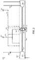
- FIG. 2depicts the turbopump system illustrated in FIG. 1 , including additional components and details, according to one or more embodiments disclosed herein.
- FIGS. 3 and 4depict the turbopump illustrated in FIG. 1 , including a thrust bearing and additional components and details, according to one or more embodiments disclosed herein.
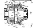
- FIG. 5depicts a cross-sectional view of the thrust bearing illustrated in FIGS. 3 and 4 , according to one or more embodiments disclosed herein.
- FIGS. 6A and 6Bdepict isometric-views of the thrust bearing illustrated in FIGS. 3 and 4 , according to one or more embodiments disclosed herein.
- FIG. 7depicts the turbopump illustrated in FIG. 1 , including additional components and details, according to one or more embodiments disclosed herein.
- FIG. 8depicts a schematic diagram of a system controller configured to operate the turbopump back-pressure regulator valve, according to one or more embodiments disclosed herein.
- FIG. 9depicts another exemplary heat engine system containing the turbopump system with the turbopump and the turbopump back-pressure regulator valve, according to one or more embodiments disclosed herein.
- FIG. 1depicts an exemplary heat engine system 90 , which may also be referred to as a thermal engine system, an electrical generation system, a waste heat or other heat recovery system, and/or a thermal to electrical energy system, as described in one of more embodiments herein.
- the heat engine system 90further contains a waste heat system 100 and a power generation system 220 coupled to and in thermal communication with each other via a working fluid circuit 202 .
- the working fluid circuit 202contains the working fluid and has a high pressure side and a low pressure side.
- the working fluid contained in the working fluid circuit 202is carbon dioxide or substantially contains carbon dioxide and may be in a supercritical state (e.g., sc-OO 2 ) and/or a subcritical state (e.g., sub-COO.
- the working fluid disposed within the high pressure side of the working fluid circuit 202contains carbon dioxide in a supercritical state and the working fluid disposed within the low pressure side of the working fluid circuit 202 contains carbon dioxide in a subcritical state.
- a heat source stream 110may be flowed through heat exchangers 120 , 130 , and/or 150 disposed within the waste heat system 100 .
- the heat exchangers 120 , 130 , and/or 150are fluidly coupled to and in thermal communication with the high pressure side of the working fluid circuit 202 , configured to be fluidly coupled to and in thermal communication with a heat source stream 110 , and configured to transfer thermal energy from the heat source stream 110 to the working fluid.
- Thermal energymay be absorbed by the working fluid within the working fluid circuit 202 and the heated working fluid may be circulated through a power turbine 228 within the power generation system 220 .
- the power turbine 228may be disposed between the high pressure side and the low pressure side of the working fluid circuit 202 and fluidly coupled to and in thermal communication with the working fluid.
- the power turbine 228may be configured to convert thermal energy to mechanical energy by a pressure drop in the working fluid flowing between the high and the low pressure sides of the working fluid circuit 202 .
- a power generator 240is coupled to the power turbine 228 and configured to convert the mechanical energy into electrical energy, a power outlet 242 electrically coupled to the power generator 240 and configured to transfer the electrical energy from the power generator 240 to an electrical grid 244 .
- the power generation system 220generally contains a rotating shaft 230 and a gearbox 232 coupled between the power turbine 228 and the power generator 240 .
- the heat engine system 90generally contains several pumps, such as a turbopump 260 and a start pump 280 , disposed within the working fluid circuit 202 and fluidly coupled between the low pressure side and the high pressure side of the working fluid circuit 202 .
- the turbopump 260 and the start pump 280may be operative to circulate and/or pressurize the working fluid throughout the working fluid circuit 202 .
- the start pump 280has a pump portion 282 and a motor-drive portion 284 .
- the start pump 280is generally an electric motorized pump or a mechanical motorized pump, and may be a variable frequency driven pump.
- the turbopump 260contains a pump portion 262 , a drive turbine 264 , a driveshaft 267 , a thrust bearing 310 , and a bearing housing 268 .
- the pump portion 262may be disposed between the high and low pressure sides of the working fluid circuit 202 and may be configured to circulate or pressurize the working fluid within the working fluid circuit 202 .
- the pump inlet on the pump portion 262is generally disposed in the low pressure side and the pump outlet on the pump portion 262 is generally disposed in the high pressure side.
- the drive turbine 264may be disposed between the high and low pressure sides of the working fluid circuit 202 and may be configured to convert a pressure drop in the working fluid to mechanical energy.
- the drive turbine 264 of the turbopump 260may be fluidly coupled to the working fluid circuit 202 downstream of the heat exchanger 150 and the pump portion 262 of the turbopump 260 may be fluidly coupled to the working fluid circuit 202 upstream of the heat exchanger 120 .
- the driveshaft 267may be coupled to and between the drive turbine 264 and the pump portion 262 , such that the drive turbine 264 may be configured to drive the pump portion 262 via the driveshaft 267 .
- the thrust bearing 310may be circumferentially disposed around the driveshaft 267 and between the drive turbine 264 and the pump portion 262 .
- the bearing housing 268may be disposed at least partially encompassing the driveshaft 267 and the thrust bearing 310 .
- a secondary heat exchangersuch as a heat exchanger 150
- the heat exchanger 150may be fluidly coupled to and in thermal communication with the heat source stream 110 and independently fluidly coupled to and in thermal communication with the working fluid in the working fluid circuit 202 .
- the heated, pressurized working fluidmay be utilized to move, drive, or otherwise power the drive turbine 264 .
- the process control system 204contains a control algorithm embedded in a computer system 206 and the control algorithm contains a governing loop controller.
- the governing controlleris generally utilized to adjust values throughout the working fluid circuit 202 for controlling the temperature, pressure, flowrate, and/or mass of the working fluid at specified points therein.
- the governing loop controllermay configured to monitor and maintain, and/or to adjust if needed, desirable threshold values of pocket pressure ratios for a thrust bearing 310 ( FIGS. 2-6B ) by modulating, adjusting, or otherwise controlling a turbopump back-pressure regulator valve 290 .
- control algorithmmay be configured to calculate valve positions for the turbopump back-pressure regulator valve 290 for providing a pump-side pocket pressure ratio (P2) of about 0.25 or less with the primary governing loop controller, a turbine-side pocket pressure ratio (P1) of about 0.25 or greater with the secondary governing loop controller, and a bearing fluid supply pressure at or greater than a critical pressure value for the bearing fluid.
- P2pump-side pocket pressure ratio
- P1turbine-side pocket pressure ratio
- bearing fluid supply pressureat or greater than a critical pressure value for the bearing fluid.
- FIGS. 1 and 2depict the turbopump system 258 , according to one or more embodiments disclosed herein.
- the turbopump system 258may be utilized to circulate and/or pressurize the working fluid within the working fluid circuit 202 .
- the turbopump system 258contains a turbopump 260 , a bearing fluid supply line 296 , a bearing fluid drain line 298 , a turbopump back-pressure regulator valve 290 , and a bearing fluid return 294 .
- the turbopump back-pressure regulator valve 290may be operatively connected or coupled to the process control system 204 , illustrated in FIGS. 1 and 9 .
- the process control system 204may be operatively connected or coupled to the turbopump back-pressure regulator valve 290 and configured to adjust the turbopump back-pressure regulator valve 290 with a control algorithm embedded in a computer system 206 .
- the bearing fluid supply line 296may be fluidly coupled to the bearing housing 268 and configured to provide a bearing fluid from the bearing fluid supply 292 , into the bearing housing 268 , and to the thrust bearing 310 , as depicted in FIG. 2 .
- the bearing fluid supply line 296may be one fluid line or split into multiple fluid lines feeding into the bearing housing 268 .
- the bearing fluid supply line 296may be fluidly coupled to a bearing fluid supply manifold 297 disposed on or in the bearing housing 268 .
- the bearing fluid supply manifold 297may be a header or a gas manifold configured to receive incoming bearing fluid or gas (e.g., bearing fluid) and distribute to one or multiple bearing supply pressure lines 287 , as illustrated in FIGS. 4 and 5 .
- the bearing supply pressure lines 287may be fluidly coupled to the bearing fluid supply manifold 297 and configured to provide the bearing fluid into different portions of the bearing housing 268 and to the thrust bearing 310 including the turbine-side thrust face 330 and the pump-side thrust face 340 .
- the bearing fluidis carbon dioxide or at least contains carbon dioxide.
- a portion of the working fluidmay be diverted from the working fluid circuit 202 or another source (e.g., storage tank or conditioning system) and utilized as the bearing fluid. Therefore, the bearing fluid and the working fluid may each independently contain carbon dioxide, such as supercritical carbon dioxide.
- FIG. 2further depicts that the bearing fluid drain line 298 may be fluidly coupled to the bearing housing 268 and configured to remove the bearing fluid from the thrust bearing 310 and the bearing housing 268 .
- the bearing fluid drain line 298may be fluidly coupled to a bearing fluid drain manifold 299 disposed on or in the bearing housing 268 .
- the bearing fluid drain line 298may be a header or a gas manifold configured to remove outgoing fluid or gas (e.g., bearing fluid) and transfer to one or multiple bearing drain pressure lines 289 , as illustrated in FIG. 5 .
- the bearing drain pressure lines 289may be fluidly coupled to the bearing fluid drain manifold 299 and configured to remove or exhaust the bearing fluid from the thrust bearing 310 including the turbine-side thrust face 330 and the pump-side thrust face 340 .
- the bearing drain pressure lines 289may merge together as a single fluid line and extend to the bearing fluid return 294 .
- the turbopump back-pressure regulator valve 290may be fluidly coupled to the bearing fluid drain line 298 and configured to control flow through the bearing fluid drain line 298 , such as between the bearing housing 268 and the bearing fluid return 294 .
- the turbopump back-pressure regulator valve 290may be configured to control the pressure, via back-pressure, within the bearing fluid drain line 298 , the bearing fluid drain manifold 299 , the bearing drain pressure line 289 , the turbine-side bearing pockets 332 and the pump-side bearing pockets 342 , the bearing supply pressure lines 287 , and the bearing fluid supply manifold 297 .
- the thrust bearing 310further contains a cylindrical body 312 , a turbine-side thrust face 330 , a pump-side thrust face 340 , a circumferential side surface 350 , and a central orifice 322 defined by and extending through the cylindrical body 312 .
- FIG. 5depicts a cross-sectional view of the thrust bearing 310 and FIGS. 6A and 6B depict isometric-views of the thrust bearing 310 .
- the central orifice 322extends along a common central axis 320 of the cylindrical body 312 , between the turbine-side thrust face 330 and the pump-side thrust face 340 , and through the cylindrical body 312 .
- the cylindrical body 312 of the thrust bearing 310may have an inner portion 314 and an outer portion 316 aligned with the common central axis 320 .
- the inner portion 314 and the outer portion 316 of the thrust bearing 310are enabled to move relative to each other.
- the inner portion 314may be configured to have movement with the driveshaft 267 and the outer portion 316 may be configured to remain stationary relative to the inner portion 314 and the driveshaft 267 .
- the turbine-side thrust face 330has a plurality of bearing pockets, such as turbine-side bearing pockets 332 , extending below the turbine-side thrust face 330 and facing the drive turbine 264 .
- the pump-side thrust face 340has a plurality of bearing pockets, such as pump-side bearing pockets 342 , extending below the pump-side thrust face 340 and facing the pump portion 262 .
- the plurality of pump-side bearing pockets 342contains from about 2 bearing pockets to about 12 bearing pockets and the plurality of turbine-side bearing pockets 332 contains from about 2 bearing pockets to about 12 bearing pockets.
- the plurality of pump-side bearing pockets 342contains from about 4 bearing pockets to about 8 bearing pockets, for example, about 6 bearing pockets and the plurality of turbine-side bearing pockets 332 contains from about 4 bearing pockets to about 8 bearing pockets, for example, about 6 bearing pockets.
- each bearing pocket of the turbine-side bearing pockets 332 and the pump-side bearing pockets 342may have a surface area, as measured on the lower surface of the pocket area, within a range from about 0.05 in 2 (about 0.32 cm 2 ) to about 1 in 2 (about 6.45 cm 2 ), more narrowly within a range from about 0.08 in 2 (about 0.52 cm 2 ) to about 0.8 in 2 (about 5.16 cm 2 ), more narrowly within a range from about 0.1 in 2 (about 0.65 cm 2 ) to about 0.5 in 2 (about 3.23 cm 2 ), and more narrowly within a range from about 0.2 in 2 (about 1.29 cm 2 ) to about 0.3 in 2 (about 2.94 cm 2 ), for example, about 0.25 in 2 (about 1.61 cm 2 ).
- each bearing pocket of the turbine-side bearing pockets 332 and the pump-side bearing pockets 342may have a pocket depth within a range from about 0.010 in (about 0.25 mm) to about 0.060 in (about 1.62 mm), more narrowly within a range from about 0.015 in (about 0.38 mm) to about 0.050 in (about 1.27 mm), more narrowly within a range from about 0.020 in (about 0.51 mm) to about 0.040 in (about 1.02 mm), and more narrowly within a range from about 0.028 in (about 0.71 mm) to about 0.032 in (about 0.81 mm), for example, about 0.030 in (about 0.76 mm).
- Each of the turbine-side bearing pockets 332contains a pocket orifice 334 and each of the pump-side bearing pockets 342 contains a pocket orifice 344 .
- the bearing pockets 332 , 342are configured to receive the bearing fluid from the bearing supply pressure lines 287 on each side of the thrust bearing 310 and to discharge the bearing fluid into their respective pocket orifices 334 , 344 .
- the pocket orifices 334 , 344extend from their respective bearing pockets 332 , 342 , through the inner portion 314 , through the outer portion 316 , out of the circumferential side surface 350 and to the bearing fluid drain manifold 299 .
- each of the turbine-side thrust face 330 and the pump-side thrust face 340has at least one pressure tap, such as a pressure tap 336 in one of the turbine-side bearing pockets 332 and a pressure tap 346 in one of the pump-side bearing pockets 342 .
- the circumferential side surface 350may extend along the circumference of the cylindrical body 312 and between the pump-side thrust face 340 and the turbine-side thrust face 330 .
- the central orifice 322extends through the cylindrical body 312 along the central axis 320 and may be configured to provide passage of the driveshaft 267 therethrough.
- FIG. 7depicts the turbopump 260 from a perspective from outside of the bearing housing 268 , according to one or more embodiments disclosed herein.
- the pump portion 262 and the drive turbine 264are contained within the bearing housing 268 which may have multiple inlets, outlets, ports, intakes/discharges, and other devices for coupling to internal components of the turbopump 260 .
- a pump inlet 352 and a pump discharge 354may be fluidly coupled to the pump portion 262 of the turbopump 260 within the bearing housing 268 .
- the pump inlet 352may be configured to be fluidly coupled to the low pressure side of the working fluid circuit 202 and the pump discharge 354 may be configured to be fluidly coupled to the high pressure side of the working fluid circuit 202 .
- a turbine inlet 356 and a turbine discharge 358may be fluidly coupled to the pump portion 262 of the turbopump 260 within the bearing housing 268 .
- the turbine inlet 356may be configured to be fluidly coupled to the high pressure side of the working fluid circuit 202 and the turbine discharge 358 may be configured to be fluidly coupled to the low pressure side of the working fluid circuit 202 .
- FIG. 7further depicts several bearing fluid supply inlets 397 on the bearing fluid supply manifold 297 , as well as at least one bearing fluid drain outlet 399 on the bearing fluid drain manifold 299 .
- the bearing fluid supply inlets 397may be configured to be fluidly coupled to the bearing fluid supply line 296 , as depicted in FIG. 7 , such that the bearing fluid may flow from the bearing fluid supply line 296 , through the bearing fluid supply inlets 397 , and into the bearing fluid supply manifold 297 .
- the bearing gasOnce within the bearing fluid supply manifold 297 , the bearing gas may flow through the bearing supply pressure lines 287 and to the thrust bearing 310 , as illustrated in FIG. 5 .
- the bearing fluidmay flow through the bearing drain pressure line 289 and into the bearing fluid drain manifold 299 , as illustrated in FIG. 5 .
- the bearing fluid drain outlet 399may be configured to be fluidly coupled to the bearing fluid drain manifold 299 , as depicted in FIG. 7 , such that the bearing fluid contained within the bearing fluid drain manifold 299 may be flowed from the bearing fluid drain manifold 299 , through the bearing fluid drain outlet 399 , and to the bearing fluid drain line 298 .
- the turbopump 260may further contain one or more pressure monitor ports 301 , as depicted in FIG. 7 .
- the pressure monitor ports 301may be configured to receive sensors or other instruments for measuring and monitoring pressures, temperatures, flowrates, and other properties within the bearing housing 268 , such as near the turbine-side thrust face 330 and the pump-side thrust face 340 , as well as within the turbine-side bearing pockets 332 , the pocket orifice 334 , the pump-side bearing pockets 342 , and/or the pocket orifice 344 .
- the control algorithmcontains a sliding mode controller configured to provide a sliding mode control method for controlling the turbopump back-pressure regulator valve 290 .
- the control algorithmgenerally contains a plurality of loop controllers configured to control the turbopump back-pressure regulator valve 290 while adjusting values of pocket pressure ratios for bearing surfaces of the thrust bearing 310 .
- the plurality of loop controllersmay be configured to adjust, modulate, or otherwise control the turbopump back-pressure regulator valve 290 in order maintain or obtain a balanced thrust of the turbopump 260 .
- the control algorithmmay be incorporated or otherwise contained within the computer system 206 as part of the process control system 204 .
- FIG. 8depicts a schematic diagram of a system controller configured to operate the turbopump back-pressure regulator valve 290 , according to one or more embodiments disclosed herein.
- the control algorithmmay contain at least a primary governing loop controller, a secondary governing loop controller, and a tertiary governing loop controller.
- the control algorithmmay be configured to calculate valve positions for the turbopump back-pressure regulator valve 290 for providing the pump-side pocket pressure ratio (P2) of about 0.25 or less with the primary governing loop controller, the turbine-side pocket pressure ratio (P1) of about 0.25 or greater with the secondary governing loop controller, and a bearing fluid supply pressure at or greater than a critical pressure value for the bearing fluid.
- P2pump-side pocket pressure ratio
- P1turbine-side pocket pressure ratio
- PP1is the pocket pressure on the turbine-side thrust face 330 in the turbine-side bearing pocket 332 and may be measured at the pressure tap 336 ,
- PP2is the pocket pressure on the pump-side thrust face 340 in the pump-side bearing pocket 342 and may be measured at the pressure tap 346 ,
- P supplyis the supply pressure of the bearing fluid and may be measured in the bearing supply pressure line 287 , the bearing fluid supply manifold 297 , and/or the bearing fluid supply line 296 ,
- P drainis the drain pressure of the bearing fluid and may be measured in the bearing drain pressure line 289 , the bearing fluid drain manifold 299 , and/or the bearing fluid drain line 298 ,
- F thrustis the thrust force, such as the thrust bearing load capacity in each direction, and
- TA pocketis the total area of the bearing pockets, which is the product of the number of—pocket is bearing pockets on one thrust face and the surface area of the bearing pocket.
- the primary governing loop controllermay be configured to adjust the turbopump back-pressure regulator valve 290 for maintaining the pump-side pocket pressure ratio (P2) of about 0.30 or less, such as about 0.25 or less, such as about 0.20 or less, such as about 0.15 or less.
- the primary governing loop controllermay be configured to activate and adjust the turbopump back-pressure regulator valve 290 if a pump-side pocket pressure ratio (P2) of about 0.25 or greater is detected by the process control system 204 .
- the pump-side pocket pressure ratio (P2)may be measured and monitored on a pump-side thrust face 340 of the thrust bearing 310 , such as with a probe or a sensor at the pressure tap 346 .
- the pump-side thrust face 340has a plurality of pump-side bearing pockets 342 extending below the pump-side thrust face 340 and facing the pump portion 262 .
- the pump-side pocket pressure ratio (P2)may be measured in the pump-side bearing pockets 342 .
- the plurality of pump-side bearing pockets 342contains about 10 bearing pockets or less and the pump-side pocket pressure ratio (P2) is about 0.25 or less.
- the secondary governing loop controllermay be configured to adjust the turbopump back-pressure regulator valve 290 for maintaining the turbine-side pocket pressure ratio (P1) of about 0.30 or less, such as about 0.25 or less, such as about 0.20 or less, such as about 0.15 or less.
- the secondary governing loop controllermay be configured to activate and adjust the turbopump back-pressure regulator valve 290 if the turbine-side pocket pressure ratio (P1) of about 0.25 or greater is detected by the process control system 204 .
- the turbine-side pocket pressure ratio (P1)may be measured on a turbine-side thrust face 330 of the thrust bearing 310 .
- the turbine-side thrust face 330has a plurality of turbine-side bearing pockets 332 extending below the turbine-side thrust face 330 and facing the drive turbine 264 .
- the turbine-side pocket pressure ratio (P1)may be measured and monitored in the turbine-side bearing pockets 332 , such as with a probe or a sensor at the pressure tap 336 .
- the plurality of turbine-side bearing pockets 332contains about 10 bearing pockets or less and the turbine-side pocket pressure ratio (P1) is about 0.25 or less.
- the tertiary governing loop controllermay be configured to activate and adjust the turbopump back-pressure regulator valve 290 if an undesirable pressure of the bearing fluid is detected by the process control system 204 .
- the undesirable pressure of the bearing fluidmay be detected at or near the bearing fluid supply line 296 .
- the undesirable pressure of the bearing fluidmay be about 5% greater than the supercritical pressure of the bearing fluid or less.
- the tertiary governing loop controllermay be configured to adjust the turbopump back-pressure regulator valve 290 for maintaining the bearing fluid in a supercritical state. In other exemplary embodiments, the tertiary governing loop controller may be configured to adjust the turbopump back-pressure regulator valve 290 for maintaining a bearing drain pressure of about 1,055 psi or greater.
- the thrust force (F thrust ), such as the thrust bearing load capacity in each direction,may be within a range from about 4,000 pound-force (lbf) (about 17.8 kilonewton (kN) to about 8,000 lbf (about 35.6 kN), more narrowly within a range from about 5,000 lbf (about 22.2 kN) to about 7,000 lbf (about 31.1 kN), and more narrowly within a range from about 5,500 lbf (about 24.5 kN) to about 6,200 lbf (about 27.6 kN), for example, about 5,700 lbf (about 25.4 kN).
- lbfpound-force
- a method for lubricating and/or cooling the turbopump 260 in the heat engine systems 90 , 200includes circulating and/or pressuring the working fluid throughout the working fluid circuit 202 with the turbopump 260 , wherein the working fluid circuit 202 has a high pressure side and a low pressure side and at least a portion of the working fluid is in a supercritical state and transferring thermal energy from the heat source stream 110 to the working fluid through at least one of the heat exchangers 120 , 130 , 150 .
- the heat exchangers 120 , 130 , 150may be fluidly coupled to and in thermal communication with the high pressure side of the working fluid circuit 202 and fluidly coupled to and in thermal communication with the heat source stream 110 .
- the methodfurther includes measuring and monitoring a turbine-side pocket pressure ratio (P1), a pump-side pocket pressure ratio (P2), a bearing fluid supply pressure, and a bearing fluid drain pressure via the process control system 204 operatively coupled to the working fluid circuit 202 , wherein the turbine-side pocket pressure ratio (P1) may be measured and/or monitored in at least one turbine-side bearing pocket 332 of a plurality of turbine-side bearing pockets 332 disposed on a turbine-side thrust face 330 of the thrust bearing 310 within the turbopump 260 , the pump-side pocket pressure ratio (P2) may be measured and/or monitored in at least one pump-side bearing pocket 342 of a plurality of pump-side bearing pockets 342 disposed on a pump-side thrust face 340 of the thrust bearing 310 , the bearing fluid supply pressure may be measured and/or monitored in at least one bearing supply pressure line 287 disposed upstream of the thrust bearing 310 , and the bearing fluid drain pressure may be measured and/or monitored in at least one bearing drain pressure line 289
- the methodalso includes controlling the turbopump back-pressure regulator valve 290 by the primary governing loop controller embedded in the process control system 204 .
- the turbopump back-pressure regulator valve 290may be fluidly coupled to the bearing fluid drain line 298 disposed downstream of the thrust bearing 310 and the primary governing loop controller may be configured to modulate the turbopump back-pressure regulator valve 290 while adjusting the pump-side pocket pressure ratio (P2).
- the methodfurther includes controlling the turbopump back-pressure regulator valve 290 by the secondary governing loop controller embedded in the process control system 204 .
- the secondary governing loop controllermay be configured to modulate the turbopump back-pressure regulator valve 290 while adjusting the turbine-side pocket pressure ratio (P1).
- the methodalso includes controlling the turbopump back-pressure regulator valve 290 by the tertiary governing loop controller embedded in the process control system 204 .
- the tertiary governing loop controllermay be configured to modulate the turbopump back-pressure regulator valve 290 while adjusting the bearing fluid supply pressure to be at or greater than a critical pressure value for the bearing fluid and maintain the bearing fluid in a supercritical state.
- a method for lubricating and/or cooling the turbopump 260 in the heat engine systems 90 , 200includes controlling the turbopump back-pressure regulator valve 290 by the primary governing loop controller embedded in the process control system 204 , wherein the turbopump back-pressure regulator valve 290 may be fluidly coupled to the bearing fluid drain line 298 disposed downstream of the thrust bearing 310 and the primary governing loop controller may be configured to modulate the turbopump back-pressure regulator valve 290 while adjusting the pump-side pocket pressure ratio (P2).
- P2pump-side pocket pressure ratio
- the methodfurther includes detecting an undesirable value of the turbine-side pocket pressure ratio (P1) via the process control system 204 and subsequently activating the secondary governing loop controller embedded in the process control system 204 , deactivating the primary governing loop controller, and decreasing the turbine-side pocket pressure ratio (P1) to a desirable value.
- the undesirable value of the turbine-side pocket pressure ratio (P1)is greater than a predetermined threshold value of the turbine-side pocket pressure ratio (P1) and the desirable value of the turbine-side pocket pressure ratio (P1) is at or less than the predetermined threshold value of the turbine-side pocket pressure ratio (P1).
- the secondary governing loop controllermay be configured to decrease the turbine-side pocket pressure ratio (P1) by modulating the turbopump back-pressure regulator valve 290 .
- the methodalso includes detecting an undesirable value of the bearing fluid supply pressure via the process control system 204 and subsequently activating the tertiary governing loop controller embedded in the process control system 204 , deactivating the primary governing loop controller or the secondary governing loop controller, and increasing the bearing fluid supply pressure to a desirable value.
- the undesirable value of the bearing fluid supply pressureis less than a critical pressure value for the bearing fluid and the desirable value of the bearing fluid supply pressure is at or greater than a critical pressure value for the bearing fluid.
- the tertiary governing loop controllermay be configured to increase the bearing fluid supply pressure by modulating the turbopump back-pressure regulator valve 290 while increasing the bearing fluid drain pressure.
- the methodmay further include adjusting the pump-side pocket pressure ratio (P2) by modulating the turbopump back-pressure regulator valve 290 with the primary governing loop controller to obtain or maintain a pump-side pocket pressure ratio (P2) of about 0.25 or less.
- the methodmay also include adjusting the turbine-side pocket pressure ratio (P1) by modulating the turbopump back-pressure regulator valve 290 with the secondary governing loop controller to obtain or maintain a turbine-side pocket pressure ratio (P1) of about 0.25 or greater.
- the methodmay further include adjusting the turbopump back-pressure regulator valve 290 with the tertiary governing loop controller to obtain or maintain the bearing drain pressure of about 1,055 psi or greater.
- the bearing fluid supply pressuremay be increased until the bearing fluid is in a supercritical state.
- the methodfurther includes regulating and maintaining the bearing fluid in a supercritical state and in physical contact or thermal communication with the thrust bearing 310 .
- the relatively cool temperature of the supercritical bearing fluide.g., sc-CO 2 ) helps to prevent damage to the thrust bearing 310 .
- the methodincludes modulating the turbopump back-pressure regulator valve 290 to control the flow of the bearing fluid passing through the bearing fluid drain line 298 .
- the turbopump back-pressure regulator valve 290is adjusted to partially opened-positions that are within a range from about 35% to about 80% of being in a fully opened-position.
- valve position or modulation range of the turbopump back-pressure regulator valve 290may be within a range from about 10% to about 95% of being in a fully opened-position, more narrowly, within a range from about 20% to about 90% of being in a fully opened-position, more narrowly, within a range from about 30% to about 85% of being in a fully opened-position, and more narrowly, within a range from about 35% to about 80% of being in a fully opened-position.
- the valve position or modulation range of the turbopump back-pressure regulator valve 290may be within a range from about 50% to about 75%, more narrowly, within a range from about 55% to about 70% of being in a fully opened-position, and more narrowly, within a range from about 60% to about 65% of being in a fully opened-position.
- FIG. 9depicts an exemplary heat engine system 200 that contains the process system 210 and the power generation system 220 fluidly coupled to and in thermal communication with the waste heat system 100 via the working fluid circuit 202 , as described in one of more embodiments herein.
- the heat engine system 200may be referred to as a thermal engine system, an electrical generation system, a waste heat or other heat recovery system, and/or a thermal to electrical energy system, as described in one of more embodiments herein.
- the heat engine system 200is generally configured to encompass one or more elements of a Rankine cycle, a derivative of a Rankine cycle, or another thermodynamic cycle for generating electrical energy from a wide range of thermal sources.
- the heat engine system 200 depicted in FIG. 9 and the heat engine systems 90 depicted in Figurelshare many common components. It should be noted that like numerals shown in the Figures and discussed herein represent like components throughout the multiple embodiments disclosed herein.
- FIG. 9depicts the working fluid circuit 202 containing the working fluid and having a high pressure side and a low pressure side, wherein at least a portion of the working fluid contains carbon dioxide in a supercritical state.
- the working fluidcontains carbon dioxide and at least a portion of the carbon dioxide is in a supercritical state.
- the heat engine system 200also has the heat exchanger 120 fluidly coupled to and in thermal communication with the high pressure side of the working fluid circuit 202 , configured to be fluidly coupled to and in thermal communication with the heat source stream 110 , and configured to transfer thermal energy from the heat source stream 110 to the working fluid within the working fluid circuit 202 .
- the heat exchanger 120may be fluidly coupled to the working fluid circuit 202 upstream of the power turbine 228 and downstream of a recuperator 216 .
- the heat engine system 200further contains the power turbine 228 disposed between the high pressure side and the low pressure side of the working fluid circuit 202 , fluidly coupled to and in thermal communication with the working fluid, and configured to convert thermal energy to mechanical energy by a pressure drop in the working fluid flowing between the high and the low pressure sides of the working fluid circuit 202 .
- the heat engine system 200also contains a power generator 240 coupled to the power turbine 228 and configured to convert the mechanical energy into electrical energy, the power outlet 242 electrically coupled to the power generator 240 and configured to transfer the electrical energy from the power generator 240 to the electrical grid 244 .
- the heat engine system 200further contains the turbopump 260 which has a drive turbine 264 and the pump portion 262 .
- the pump portion 262 of the turbopump 260may be fluidly coupled to the low pressure side of the working fluid circuit 202 by an inlet configured to receive the working fluid from the low pressure side of the working fluid circuit 202 , fluidly coupled to the high pressure side of the working fluid circuit 202 by an outlet configured to release the working fluid into the high pressure side of the working fluid circuit 202 , and configured to circulate the working fluid within the working fluid circuit 202 .
- the drive turbine 264 of the turbopump 260may be fluidly coupled to the high pressure side of the working fluid circuit 202 by an inlet configured to receive the working fluid from the high pressure side of the working fluid circuit 202 , fluidly coupled to the low pressure side of the working fluid circuit 202 by an outlet configured to release the working fluid into the low pressure side of the working fluid circuit 202 , and configured to rotate the pump portion 262 of the turbopump 260 .
- the heat exchanger 150may be configured to be fluidly coupled to and in thermal communication with the heat source stream 110 . Also, the heat exchanger 150 may be fluidly coupled to and in thermal communication with the high pressure side of the working fluid circuit 202 . Therefore, thermal energy may be transferred from the heat source stream 110 , through the heat exchanger 150 , and to the working fluid within the working fluid circuit 202 . The heat exchanger 150 may be fluidly coupled to the working fluid circuit 202 upstream of the outlet of the pump portion 262 of the turbopump 260 and downstream of the inlet of the drive turbine 264 of the turbopump 260 .
- the drive turbine throttle valve 263may be fluidly coupled to the working fluid circuit 202 downstream of the heat exchanger 150 and upstream of the inlet of the drive turbine 264 of the turbopump 260 .
- the working fluid containing the absorbed thermal energyflows from the heat exchanger 150 to the drive turbine 264 of the turbopump 260 via the drive turbine throttle valve 263 . Therefore, in some embodiments, the drive turbine throttle valve 263 may be utilized to control the flowrate of the heated working fluid flowing from the heat exchanger 150 to the drive turbine 264 of the turbopump 260 .
- the recuperator 216may be fluidly coupled to the working fluid circuit 202 and configured to transfer thermal energy from the working fluid within the low pressure side to the working fluid within the high pressure side of the working fluid circuit 202 .
- a recuperator 218may be fluidly coupled to the working fluid circuit 202 downstream of the outlet of the pump portion 262 of the turbopump 260 and upstream of the heat exchanger 150 and configured to transfer thermal energy from the working fluid within the low pressure side to the working fluid within the high pressure side of the working fluid circuit 202 .
- FIG. 9further depicts that the waste heat system 100 of the heat engine system 200 contains three heat exchangers (e.g., the heat exchangers 120 , 130 , and 150 ) fluidly coupled to the high pressure side of the working fluid circuit 202 and in thermal communication with the heat source stream 110 .
- Such thermal communicationprovides the transfer of thermal energy from the heat source stream 110 to the working fluid flowing throughout the working fluid circuit 202 .
- two, three, or more heat exchangersmay be fluidly coupled to and in thermal communication with the working fluid circuit 202 , such as a primary heat exchanger, a secondary heat exchanger, a tertiary heat exchanger, respectively the heat exchangers 120 , 150 , and 130 , and/or an optional quaternary heat exchanger (not shown).
- the heat exchanger 120may be the primary heat exchanger fluidly coupled to the working fluid circuit 202 upstream of an inlet of the power turbine 228
- the heat exchanger 150may be the secondary heat exchanger fluidly coupled to the working fluid circuit 202 upstream of an inlet of the drive turbine 264 of the turbine pump 260
- the heat exchanger 130may be the tertiary heat exchanger fluidly coupled to the working fluid circuit 202 upstream of an inlet of the heat exchanger 120 .
- the waste heat system 100also contains an inlet 104 for receiving the heat source stream 110 and an outlet 106 for passing the heat source stream 110 out of the waste heat system 100 .
- the heat source stream 110flows through and from the inlet 104 , through the heat exchanger 120 , through one or more additional heat exchangers, if fluidly coupled to the heat source stream 110 , and to and through the outlet 106 .
- the heat source stream 110flows through and from the inlet 104 , through the heat exchangers 120 , 150 , and 130 , respectively, and to and through the outlet 106 .
- the heat source stream 110may be routed to flow through the heat exchangers 120 , 130 , 150 , and/or additional heat exchangers in other desired orders.
- the heat source stream 110may be a waste heat stream such as, but not limited to, gas turbine exhaust stream, industrial process exhaust stream, or other combustion product exhaust streams, such as furnace or boiler exhaust streams.
- the heat source stream 110may be at a temperature within a range from about 100° C. to about 1,000° C., or greater than 1,000° C., and in some examples, within a range from about 200° C. to about 800° C., more narrowly within a range from about 300° C. to about 700° C., and more narrowly within a range from about 400° C. to about 600° C., for example, within a range from about 500° C. to about 550° C.
- the heat source stream 110may contain air, carbon dioxide, carbon monoxide, water or steam, nitrogen, oxygen, argon, derivatives thereof, or mixtures thereof.
- the heat source stream 110may derive thermal energy from renewable sources of thermal energy, such as solar or geothermal sources.
- the types of working fluid that may be circulated, flowed, or otherwise utilized in the working fluid circuit 202 of the heat engine system 200include carbon oxides, hydrocarbons, alcohols, ketones, halogenated hydrocarbons, ammonia, amines, aqueous, or combinations thereof.
- Exemplary working fluids that may be utilized in the heat engine system 200include carbon dioxide, ammonia, methane, ethane, propane, butane, ethylene, propylene, butylene, acetylene, methanol, ethanol, acetone, methyl ethyl ketone, water, derivatives thereof, or mixtures thereof.
- Halogenated hydrocarbonsmay include hydrochlorofluorocarbons (HCFCs), hydrofluorocarbons (HFCs) (e.g., 1,1,1,3,3-pentafluoropropane (R245fa)), fluorocarbons, derivatives thereof, or mixtures thereof.
- HCFCshydrochlorofluorocarbons
- HFCshydrofluorocarbons
- R245fa1,1,1,3,3-pentafluoropropane
- the working fluid circulated, flowed, or otherwise utilized in the working fluid circuit 202 of the heat engine system 200may be or may contain carbon dioxide (CO 2 ) and mixtures containing carbon dioxide.
- CO 2carbon dioxide
- the working fluid circuit 202contains the working fluid in a supercritical state (e.g., sc-CO 2 ).
- Carbon dioxide utilized as the working fluid or contained in the working fluid for power generation cycleshas many advantages over other compounds typical used as working fluids, since carbon dioxide has the properties of being non-toxic and non-flammable and is also easily available and relatively inexpensive.
- a carbon dioxide systemmay be much more compact than systems using other working fluids.
- the high density and volumetric heat capacity of carbon dioxide with respect to other working fluidsmakes carbon dioxide more “energy dense” meaning that the size of all system components can be considerably reduced without losing performance.
- carbon dioxideCO 2
- sc-CO 2supercritical carbon dioxide
- sub-CO 2subcritical carbon dioxide
- use of the terms carbon dioxide (CO 2 ), supercritical carbon dioxide (sc-CO 2 ), or subcritical carbon dioxide (sub-CO 2 )is not intended to be limited to carbon dioxide of any particular type, source, purity, or grade.
- industrial grade carbon dioxidemay be contained in and/or used as the working fluid without departing from the scope of the disclosure.
- the working fluid in the working fluid circuit 202may be a binary, ternary, or other working fluid blend.
- the working fluid blend or combinationcan be selected for the unique attributes possessed by the fluid combination within a heat recovery system, as described herein.
- one such fluid combinationincludes a liquid absorbent and carbon dioxide mixture enabling the combined fluid to be pumped in a liquid state to high pressure with less energy input than required to compress carbon dioxide.
- the working fluidmay be a combination of carbon dioxide (e.g., sub-CO 2 or sc-CO 2 ) and one or more other miscible fluids or chemical compounds.
- the working fluidmay be a combination of carbon dioxide and propane, or carbon dioxide and ammonia, without departing from the scope of the disclosure.
- the working fluid circuit 202generally has a high pressure side and a low pressure side and contains a working fluid circulated within the working fluid circuit 202 .
- the use of the term “working fluid”is not intended to limit the state or phase of matter of the working fluid.
- the working fluid or portions of the working fluidmay be in a liquid phase, a gas phase, a fluid phase, a subcritical state, a supercritical state, or any other phase or state at any one or more points within the heat engine system 200 or thermodynamic cycle.
- the working fluidis in a supercritical state over certain portions of the working fluid circuit 202 of the heat engine system 200 (e.g., a high pressure side) and in a subcritical state over other portions of the working fluid circuit 202 of the heat engine system 200 (e.g., a low pressure side).
- FIG. 9depicts the high and low pressure sides of the working fluid circuit 202 of the heat engine system 200 by representing the high pressure side with “------” and the low pressure side with “-.-.-.”—as described in one or more embodiments.
- the entire thermodynamic cyclemay be operated such that the working fluid is maintained in either a supercritical or subcritical state throughout the entire working fluid circuit 202 of the heat engine system 200 .
- the high pressure side of the working fluid circuit 202contains the working fluid (e.g., sc-CO 2 ) at a pressure of about 15 MPa or greater, such as about 17 MPa or greater or about 20 MPa or greater.
- the high pressure side of the working fluid circuit 202may have a pressure within a range from about 15 MPa to about 30 MPa, more narrowly within a range from about 16 MPa to about 26 MPa, more narrowly within a range from about 17 MPa to about 25 MPa, and more narrowly within a range from about 17 MPa to about 24 MPa, such as about 23.3 MPa.
- the high pressure side of the working fluid circuit 202may have a pressure within a range from about 20 MPa to about 30 MPa, more narrowly within a range from about 21 MPa to about 25 MPa, and more narrowly within a range from about 22 MPa to about 24 MPa, such as about 23 MPa.
- the low pressure side of the working fluid circuit 202contains the working fluid (e.g., CO 2 or sub-CO 2 ) at a pressure of less than 15 MPa, such as about 12 MPa or less or about 10 MPa or less.
- the low pressure side of the working fluid circuit 202may have a pressure within a range from about 4 MPa to about 14 MPa, more narrowly within a range from about 6 MPa to about 13 MPa, more narrowly within a range from about 8 MPa to about 12 MPa, and more narrowly within a range from about 10 MPa to about 11 MPa, such as about 10.3 MPa.
- the low pressure side of the working fluid circuit 202may have a pressure within a range from about 2 MPa to about 10 MPa, more narrowly within a range from about 4 MPa to about 8 MPa, and more narrowly within a range from about 5 MPa to about 7 MPa, such as about 6 MPa.
- the high pressure side of the working fluid circuit 202may have a pressure within a range from about 17 MPa to about 23.5 MPa, and more narrowly within a range from about 23 MPa to about 23.3 MPa while the low pressure side of the working fluid circuit 202 may have a pressure within a range from about 8 MPa to about 11 MPa, and more narrowly within a range from about 10.3 MPa to about 11 MPa.
- the heat engine system 200further contains the power turbine 228 disposed between the high pressure side and the low pressure side of the working fluid circuit 202 , disposed downstream of the heat exchanger 120 , and fluidly coupled to and in thermal communication with the working fluid.
- the power turbine 228may be configured to convert a pressure drop in the working fluid to mechanical energy whereby the absorbed thermal energy of the working fluid is transformed to mechanical energy of the power turbine 228 . Therefore, the power turbine 228 is an expansion device capable of transforming a pressurized fluid into mechanical energy, generally, transforming high temperature and pressure fluid into mechanical energy, such as rotating a shaft.
- the power turbine 228may contain or be a turbine, a turbo, an expander, or another device for receiving and expanding the working fluid discharged from the heat exchanger 120 .
- the power turbine 228may have an axial construction or radial construction and may be a single-staged device or a multi-staged device.
- Exemplary turbines that may be utilized in power turbine 228include an expansion device, a geroler, a gerotor, a valve, other types of positive displacement devices such as a pressure swing, a turbine, a turbo, or any other device capable of transforming a pressure or pressure/enthalpy drop in a working fluid into mechanical energy.
- a variety of different types of expanding devicesmay be utilized as the power turbine 228 to achieve various performance properties.
- the power turbine 228is generally coupled to the power generator 240 by the rotating shaft 230 .
- the gearbox 232is generally disposed between the power turbine 228 and the power generator 240 and adjacent or encompassing the rotating shaft 230 .
- the rotating shaft 230may be a single piece or contain two or more pieces coupled together. In one or more examples, a first segment of the rotating shaft 230 extends from the power turbine 228 to the gearbox 232 , a second segment of the rotating shaft 230 extends from the gearbox 232 to the power generator 240 , and multiple gears are disposed between and coupled to the two segments of the rotating shaft 230 within the gearbox 232 .
- the heat engine system 200also provides for the delivery of a portion of the working fluid, seal gas, bearing gas, air, or other gas into a chamber or housing, such as a housing 238 within the power generation system 220 for purposes of cooling one or more parts of the power turbine 228 .
- the rotating shaft 230includes a seal assembly (not shown) designed to prevent or capture any working fluid leakage from the power turbine 228 .
- a working fluid recycle systemmay be implemented along with the seal assembly to recycle seal gas back into the working fluid circuit 202 of the heat engine system 200 .
- the power generator 240may be a generator, an alternator (e.g., permanent magnet alternator), or other device for generating electrical energy, such as transforming mechanical energy from the rotating shaft 230 and the power turbine 228 to electrical energy.
- the power outlet 242may be electrically coupled to the power generator 240 and configured to transfer the generated electrical energy from the power generator 240 and to the electrical grid 244 .
- the electrical grid 244may be or include an electrical grid, an electrical bus (e.g., plant bus), power electronics, other electric circuits, or combinations thereof.
- the electrical grid 244generally contains at least one alternating current bus, alternating current grid, alternating current circuit, or combinations thereof.
- the power generator 240is a generator and is electrically and operatively connected or coupled to the electrical grid 244 via the power outlet 242 .
- the power generator 240is an alternator and is electrically and operatively connected to power electronics (not shown) via the power outlet 242 .
- the power generator 240is electrically connected to power electronics which are electrically connected to the power outlet 242 .
- the power electronicsmay be configured to convert the electrical power into desirable forms of electricity by modifying electrical properties, such as voltage, current, or frequency.
- the power electronicsmay include converters or rectifiers, inverters, transformers, regulators, controllers, switches, resisters, storage devices, and other power electronic components and devices.
- the power generator 240may contain, be coupled with, or be other types of load receiving equipment, such as other types of electrical generation equipment, rotating equipment, a gearbox (e.g., the gearbox 232 ), or other device configured to modify or convert the shaft work created by the power turbine 228 .
- the power generator 240is in fluid communication with a cooling loop having a radiator and a pump for circulating a cooling fluid, such as water, thermal oils, and/or other suitable refrigerants.
- the cooling loopmay be configured to regulate the temperature of the power generator 240 and power electronics by circulating the cooling fluid to draw away generated heat.
- the heat engine system 200also provides for the delivery of a portion of the working fluid into a chamber or housing of the power turbine 228 for purposes of cooling one or more parts of the power turbine 228 .
- the selection of the site within the heat engine system 200 from which to obtain a portion of the working fluidis critical because introduction of this portion of the working fluid into the power generator 240 should respect or not disturb the pressure balance and stability of the power generator 240 during operation. Therefore, the pressure of the working fluid delivered into the power generator 240 for purposes of cooling is the same or substantially the same as the pressure of the working fluid at an inlet of the power turbine 228 .
- the working fluidis conditioned to be at a desired temperature and pressure prior to being introduced into the power turbine 228 .
- the recuperators 216 and 218may be fluidly coupled to the working fluid circuit 202 in series with each other.
- the recuperators 216 and 218are operative to transfer thermal energy between the high pressure side and the low pressure side of the working fluid circuit 202 .
- the recuperator 216is fluidly coupled to the low pressure side of the working fluid circuit 202 , disposed downstream of a working fluid outlet on the power turbine 228 , and disposed upstream of the recuperator 218 and/or the condenser 274 .
- the recuperator 216may be configured to remove at least a portion of thermal energy from the working fluid discharged from the power turbine 228 .
- the recuperator 216is also fluidly coupled to the high pressure side of the working fluid circuit 202 , disposed upstream of the heat exchanger 120 and/or a working fluid inlet on the power turbine 228 , and disposed downstream of the heat exchanger 130 .
- the recuperator 216may be configured to increase the amount of thermal energy in the working fluid prior to flowing into the heat exchanger 120 and/or the power turbine 228 . Therefore, the recuperator 216 is operative to transfer thermal energy between the high pressure side and the low pressure side of the working fluid circuit 202 .
- the recuperator 216may be a heat exchanger configured to cool the low pressurized working fluid discharged or downstream of the power turbine 228 while heating the high pressurized working fluid entering into or upstream of the heat exchanger 120 and/or the power turbine 228 .
- the recuperator 218is fluidly coupled to the low pressure side of the working fluid circuit 202 , disposed downstream of a working fluid outlet on the power turbine 228 and/or the recuperator 216 , and disposed upstream of the condenser 274 .
- the recuperator 218may be configured to remove at least a portion of thermal energy from the working fluid discharged from the power turbine 228 and/or the recuperator 216 .
- recuperator 218is also fluidly coupled to the high pressure side of the working fluid circuit 202 , disposed upstream of the heat exchanger 150 and/or a working fluid inlet on the drive turbine 264 of turbopump 260 , and disposed downstream of a working fluid outlet on the pump portion 262 of the turbopump 260 .
- the recuperator 218may be configured to increase the amount of thermal energy in the working fluid prior to flowing into the heat exchanger 150 and/or the drive turbine 264 . Therefore, the recuperator 218 is operative to transfer thermal energy between the high pressure side and the low pressure side of the working fluid circuit 202 .
- the recuperator 218may be a heat exchanger configured to cool the low pressurized working fluid discharged or downstream of the power turbine 228 and/or the recuperator 216 while heating the high pressurized working fluid entering into or upstream of the heat exchanger 150 and/or the drive turbine 264 .
- a cooler or a condenser 274may be fluidly coupled to and in thermal communication with the low pressure side of the working fluid circuit 202 and may be configured or operative to control a temperature of the working fluid in the low pressure side of the working fluid circuit 202 .
- the condenser 274may be disposed downstream of the recuperators 216 and 218 and upstream of the start pump 280 and the turbopump 260 .
- the condenser 274receives the cooled working fluid from the recuperator 218 and further cools and/or condenses the working fluid which may be recirculated throughout the working fluid circuit 202 .
- the condenser 274is a cooler and may be configured to control a temperature of the working fluid in the low pressure side of the working fluid circuit 202 by transferring thermal energy from the working fluid in the low pressure side to a cooling loop or system outside of the working fluid circuit 202 .
- a cooling media or fluidis generally utilized in the cooling loop or system by the condenser 274 for cooling the working fluid and removing thermal energy outside of the working fluid circuit 202 .
- the cooling media or fluidflows through, over, or around while in thermal communication with the condenser 274 . Thermal energy in the working fluid is transferred to the cooling fluid via the condenser 274 . Therefore, the cooling fluid is in thermal communication with the working fluid circuit 202 , but not fluidly coupled to the working fluid circuit 202 .
- the condenser 274may be fluidly coupled to the working fluid circuit 202 and independently fluidly coupled to the cooling fluid.
- the cooling fluidmay contain one or multiple compounds and may be in one or multiple states of matter.
- the cooling fluidmay be a media or fluid in a gaseous state, a liquid state, a subcritical state, a supercritical state, a suspension, a solution, derivatives thereof, or combinations thereof.
- the condenser 274is generally fluidly coupled to a cooling loop or system (not shown) that receives the cooling fluid from a cooling fluid return 278 a and returns the warmed cooling fluid to the cooling loop or system via a cooling fluid supply 278 b .
- the cooling fluidmay be water, carbon dioxide, or other aqueous and/or organic fluids (e.g., alcohols and/or glycols), air or other gases, or various mixtures thereof that is maintained at a lower temperature than the temperature of the working fluid.
- the cooling media or fluidcontains air or another gas exposed to the condenser 274 , such as an air steam blown by a motorized fan or blower.
- a filter 276may be disposed along and in fluid communication with the cooling fluid line at a point downstream of the cooling fluid supply 278 b and upstream of the condenser 274 .
- the filter 276may be fluidly coupled to the cooling fluid line within the process system 210 .
- the heat engine system 200further contains several pumps, such as the turbopump 260 and the start pump 280 , disposed within the working fluid circuit 202 and fluidly coupled between the low pressure side and the high pressure side of the working fluid circuit 202 .
- the turbopump 260 and the start pump 280are operative to circulate the working fluid throughout the working fluid circuit 202 .
- the start pump 280is generally a motorized pump and may be utilized to initially pressurize and circulate the working fluid in the working fluid circuit 202 . Once a predetermined pressure, temperature, and/or flowrate of the working fluid is obtained within the working fluid circuit 202 , the start pump 280 may be taken off line, idled, or turned off and the turbopump 260 is utilize to circulate the working fluid during the electricity generation process.
- the working fluidmay enter the pump portion 262 of the turbopump 260 and the pump portion 282 of the start pump 280 from the low pressure side of the working fluid circuit 202 and may be discharged from the pump portions 262 , 282 into the high pressure side of the working fluid circuit 202 .
- the start pump 280may be a motorized pump, such as an electric motorized pump, a mechanical motorized pump, or other type of pump.
- the start pump 280may be a variable frequency motorized drive pump and contains a pump portion 282 and a motor-drive portion 284 .
- the motor-drive portion 284 of the start pump 280contains a motor and a drive including a driveshaft and gears.
- the motor-drive portion 284has a variable frequency drive, such that the speed of the motor may be regulated by the drive.
- the pump portion 282 of the start pump 280is driven by the motor-drive portion 284 coupled thereto.
- the pump portion 282has an inlet for receiving the working fluid from the low pressure side of the working fluid circuit 202 , such as from the condenser 274 and/or the mass management system 270 .
- the pump portion 282has an outlet for releasing the working fluid into the high pressure side of the working fluid circuit 202 .
- a start pump inlet valve 283 and a start pump outlet valve 285may be utilized to control the flow of the working fluid passing through the start pump 280 .
- the start pump inlet valve 283may be fluidly coupled to the low pressure side of the working fluid circuit 202 upstream of the pump portion 282 of the start pump 280 and may be utilized to control the flowrate of the working fluid entering the inlet of the pump portion 282 .
- the start pump outlet valve 285may be fluidly coupled to the high pressure side of the working fluid circuit 202 downstream of the pump portion 282 of the start pump 280 and may be utilized to control the flowrate of the working fluid exiting the outlet of the pump portion 282 .
- the drive turbine 264 of the turbopump 260may be driven by heated working fluid, such as the working fluid flowing from the heat exchanger 150 .
- the drive turbine 264is fluidly coupled to the high pressure side of the working fluid circuit 202 by an inlet configured to receive the working fluid from the high pressure side of the working fluid circuit 202 , such as flowing from the heat exchanger 150 .
- the drive turbine 264is fluidly coupled to the low pressure side of the working fluid circuit 202 by an outlet configured to release the working fluid into the low pressure side of the working fluid circuit 202 .
- the pump portion 262 of the turbopump 260may be driven via the driveshaft 267 coupled to the drive turbine 264 .
- the pump portion 262 of the turbopump 260may be fluidly coupled to the low pressure side of the working fluid circuit 202 by an inlet configured to receive the working fluid from the low pressure side of the working fluid circuit 202 .
- the inlet of the pump portion 262may be configured to receive the working fluid from the low pressure side of the working fluid circuit 202 , such as from the condenser 274 and/or the mass management system 270 .
- the pump portion 262may be fluidly coupled to the high pressure side of the working fluid circuit 202 by an outlet configured to release the working fluid into the high pressure side of the working fluid circuit 202 and circulate the working fluid within the working fluid circuit 202 .
- the driveshaft 267may be a single piece or contain two or more pieces coupled together.
- a first segment of the driveshaft 267extends from the drive turbine 264 to the gearbox
- a second segment of the rotating shaft 230extends from the gearbox to the pump portion 262
- multiple gearsare disposed between and coupled to the two segments of the driveshaft 267 within the gearbox.
- the working fluid released from the outlet on the drive turbine 264is returned into the working fluid circuit 202 downstream of the recuperator 216 and upstream of the recuperator 218 .
- the turbopump 260including piping and valves, is optionally disposed on a turbopump skid 266 , as depicted in FIG. 9 .
- the turbopump skid 266may be disposed on or adjacent to the main process skid 212 .
- a drive turbine bypass valve 265is generally coupled between and in fluid communication with a fluid line extending from the inlet on the drive turbine 264 with a fluid line extending from the outlet on the drive turbine 264 .
- the drive turbine bypass valve 265is generally opened to bypass the turbopump 260 while using the start pump 280 during the initial stages of generating electricity with the heat engine system 200 .
- the drive turbine bypass valve 265is closed and the heated working fluid is flowed through the drive turbine 264 to start the turbopump 260 .
- a drive turbine throttle valve 263may be coupled between and in fluid communication with a fluid line extending from the heat exchanger 150 to the inlet on the drive turbine 264 of the turbopump 260 .
- the drive turbine throttle valve 263may be configured to modulate the flow of the heated working fluid into the drive turbine 264 which in turn—may be utilized to adjust the flow of the working fluid throughout the working fluid circuit 202 .
- a valve 293may be utilized to control the flow of the working fluid passing through the high pressure side of the recuperator 218 and through the heat exchanger 150 . The additional thermal energy absorbed by the working fluid from the recuperator 218 and the heat exchanger 150 is transferred to the drive turbine 264 for powering or otherwise driving the pump portion 262 of the turbopump 260 .
- the valve 293may be utilized to provide and/or control back pressure for the drive turbine 264 of the turbopump 260 .
- a drive turbine attemperator valve 295may be fluidly coupled to the working fluid circuit 202 via an attemperator bypass line 291 disposed between the outlet on the pump portion 262 of the turbopump 260 and the inlet on the drive turbine 264 and/or disposed between the outlet on the pump portion 282 of the start pump 280 and the inlet on the drive turbine 264 .
- the attemperator bypass line 291 and the drive turbine attemperator valve 295may be configured to flow the working fluid from the pump portion 262 or 282 , around and avoid the recuperator 218 and the heat exchanger 150 , and to the drive turbine 264 , such as during a warm-up or cool-down step of the turbopump 260 .
- the attemperator bypass line 291 and the drive turbine attemperator valve 295may be utilized to warm the working fluid with the drive turbine 264 while avoiding the thermal heat from the heat source stream 110 via the heat exchangers, such as the heat exchanger 150 .
- the check valve 261may be disposed downstream of the outlet of the pump portion 262 of the turbopump 260 and the check valve 281 may be disposed downstream of the outlet of the pump portion 282 of the start pump 280 .
- the check valves 261 and 281are flow control safety valves and may be utilized to release an over-pressure, regulate the directional flow, or prohibit backflow of the working fluid within the working fluid circuit 202 .
- the check valve 261may be configured to prevent the working fluid from flowing upstream towards or into the outlet of the pump portion 262 of the turbopump 260 .
- check valve 281may be configured to prevent the working fluid from flowing upstream towards or into the outlet of the pump portion 282 of the start pump 280 .
- the drive turbine throttle valve 263is fluidly coupled to the working fluid circuit 202 upstream of the inlet of the drive turbine 264 of the turbopump 260 and configured to control a flow of the working fluid flowing into the drive turbine 264 .
- the power turbine bypass valve 219is fluidly coupled to the power turbine bypass line 208 and configured to modulate, adjust, or otherwise control the working fluid flowing through the power turbine bypass line 208 for controlling the flowrate of the working fluid entering the power turbine 228 .
- the power turbine bypass line 208is fluidly coupled to the working fluid circuit 202 at a point upstream of an inlet of the power turbine 228 and at a point downstream of an outlet of the power turbine 228 .
- the power turbine bypass line 208may be configured to flow the working fluid around and avoid the power turbine 228 when the power turbine bypass valve 219 is in an open-position.
- the flowrate and the pressure of the working fluid flowing into the power turbine 228may be reduced or stopped by adjusting the power turbine bypass valve 219 to the open-position.
- the flowrate and the pressure of the working fluid flowing into the power turbine 228may be increased or started by adjusting the power turbine bypass valve 219 to the closed-position due to the backpressure formed through the power turbine bypass line 208 .
- the power turbine bypass valve 219 and the drive turbine throttle valve 263may be independently controlled by the process control system 204 that is communicably connected, wired and/or wirelessly, with the power turbine bypass valve 219 , the drive turbine throttle valve 263 , and other parts of the heat engine system 200 .
- the process control system 204is operatively connected to the working fluid circuit 202 and a mass management system 270 and is enabled to monitor and control multiple process operation parameters of the heat engine system 200 .
- the working fluid circuit 202provides a bypass flowpath for the start pump 280 via the start pump bypass line 224 and a start pump bypass valve 254 , as well as a bypass flowpath for the turbopump 260 via the turbopump bypass line 226 and a turbopump bypass valve 256 .
- One end of the start pump bypass line 224is fluidly coupled to an outlet of the pump portion 282 of the start pump 280 and the other end of the start pump bypass line 224 is fluidly coupled to a fluid line 229 .
- a turbopump bypass line 226is fluidly coupled to an outlet of the pump portion 262 of the turbopump 260 and the other end of the turbopump bypass line 226 is coupled to the start pump bypass line 224 .
- the start pump bypass line 224 and the turbopump bypass line 226merge together as a single line upstream of coupling to a fluid line 229 .
- the fluid line 229extends between and is fluidly coupled to the recuperator 218 and the condenser 274 .
- the start pump bypass valve 254may be disposed along the start pump bypass line 224 and fluidly coupled between the low pressure side and the high pressure side of the working fluid circuit 202 when in a closed-position.
- the turbopump bypass valve 256may be disposed along the turbopump bypass line 226 and fluidly coupled between the low pressure side and the high pressure side of the working fluid circuit 202 when in a closed-position.
- FIG. 9further depicts a power turbine throttle valve 250 fluidly coupled to a bypass line 246 on the high pressure side of the working fluid circuit 202 and upstream of the heat exchanger 120 , as disclosed by at least one embodiment described herein.
- the power turbine throttle valve 250is fluidly coupled to the bypass line 246 and configured to modulate, adjust, or otherwise control the working fluid flowing through the bypass line 246 for controlling a general coarse flowrate of the working fluid within the working fluid circuit 202 .
- the bypass line 246is fluidly coupled to the working fluid circuit 202 at a point upstream of the valve 293 and at a point downstream of the pump portion 282 of the start pump 280 and/or the pump portion 262 of the turbopump 260 .
- a power turbine trim valve 252is fluidly coupled to a bypass line 248 on the high pressure side of the working fluid circuit 202 and upstream of the heat exchanger 150 , as disclosed by another embodiment described herein.
- the power turbine trim valve 252is fluidly coupled to the bypass line 248 and configured to modulate, adjust, or otherwise control the working fluid flowing through the bypass line 248 for controlling a fine flowrate of the working fluid within the working fluid circuit 202 .
- the bypass line 248is fluidly coupled to the bypass line 246 at a point upstream of the power turbine throttle valve 250 and at a point downstream of the power turbine throttle valve 250 .
- the heat engine system 200further contains a drive turbine throttle valve 263 fluidly coupled to the working fluid circuit 202 upstream of the inlet of the drive turbine 264 of the turbopump 260 and configured to modulate a flow of the working fluid flowing into the drive turbine 264 , a power turbine bypass line 208 fluidly coupled to the working fluid circuit 202 upstream of an inlet of the power turbine 228 , fluidly coupled to the working fluid circuit 202 downstream of an outlet of the power turbine 228 , and configured to flow the working fluid around and avoid the power turbine 228 , a power turbine bypass valve 219 fluidly coupled to the power turbine bypass line 208 and configured to modulate a flow of the working fluid flowing through the power turbine bypass line 208 for controlling the flowrate of the working fluid entering the power turbine 228 , and a process control system 204 operatively connected to the heat engine system 90 or 200 , wherein the process control system 204 may be configured to adjust the drive turbine throttle valve 263 and the power turbine bypass valve 219 .
- a heat exchanger bypass line 160is fluidly coupled to a fluid line 131 of the working fluid circuit 202 upstream of the heat exchangers 120 , 130 , and/or 150 by a heat exchanger bypass valve 162 , as illustrated in FIG. 9 .
- the heat exchanger bypass valve 162may be a solenoid valve, a hydraulic valve, an electric valve, a manual valve, or derivatives thereof.
- the heat exchanger bypass valve 162is a solenoid valve and configured to be controlled by the process control system 204 .
- the working fluid circuit 202provides release valves 213 a , 213 b , 213 c , and 213 d , as well as release outlets 214 a , 214 b , 214 c , and 214 d , respectively in fluid communication with each other.
- the release valves 213 a , 213 b , 213 c , and 213 dremain closed during the electricity generation process, but may be configured to automatically open to release an over-pressure at a predetermined value within the working fluid.
- the working fluidis vented through the respective release outlet 214 a , 214 b , 214 c , or 214 d .
- the release outlets 214 a , 214 b , 214 c , and 214 dmay provide passage of the working fluid into the ambient surrounding atmosphere.
- the release outlets 214 a , 214 b , 214 c , and 214 dmay provide passage of the working fluid into a recycling or reclamation step that generally includes capturing, condensing, and storing the working fluid.
- the release valve 213 a and the release outlet 214 aare fluidly coupled to the working fluid circuit 202 at a point disposed between the heat exchanger 120 and the power turbine 228 .
- the release valve 213 b and the release outlet 214 bare fluidly coupled to the working fluid circuit 202 at a point disposed between the heat exchanger 150 and the turbo portion 264 of the turbopump 260 .
- the release valve 213 c and the release outlet 214 care fluidly coupled to the working fluid circuit 202 via a bypass line that extends from a point between the valve 293 and the pump portion 262 of the turbopump 260 to a point on the turbopump bypass line 226 between the turbopump bypass valve 256 and the fluid line 229 .
- the release valve 213 d and the release outlet 214 dare fluidly coupled to the working fluid circuit 202 at a point disposed between the recuperator 218 and the condenser 274 .
- a computer system 206contains a multi-controller algorithm utilized to control the drive turbine throttle valve 263 , the power turbine bypass valve 219 , the heat exchanger bypass valve 162 , the power turbine throttle valve 250 , the power turbine trim valve 252 , as well as other valves, pumps, and sensors within the heat engine system 200 .
- the process control system 204is enabled to move, adjust, manipulate, or otherwise control the heat exchanger bypass valve 162 , the power turbine throttle valve 250 , and/or the power turbine trim valve 252 for adjusting or controlling the flow of the working fluid throughout the working fluid circuit 202 .
- the process control system 204is also operable to regulate the temperatures and pressures throughout the working fluid circuit 202 .
- FIGS. 1 and 9depicts the heat engine systems 90 , 200 containing the mass management system (MMS) 270 fluidly coupled to the working fluid circuit 202 , as described by another exemplary embodiment.
- the mass management system 270also referred to as an inventory management system, may be utilized to control the amount of working fluid added to, contained within, or removed from the working fluid circuit 202 .
- the mass management system 270may have two or more transfer lines that may be configured to have one-directional flow, such an inventory return line 172 and an inventory supply line 182 . Therefore, the mass management system 270 may contain the mass control tank 286 and the transfer pump 170 connected in series by an inventory line 176 and may further contain the inventory return line 172 and the inventory supply line 182 .
- the inventory return line 172may be fluidly coupled between the working fluid circuit 202 and the mass control tank 286 .
- An inventory return valve 174may be fluidly coupled to the inventory return line 172 and configured to remove the working fluid from the working fluid circuit 202 .
- the inventory supply line 182may be fluidly coupled between the transfer pump 170 and the working fluid circuit 202 .
- An inventory supply valve 184may be fluidly coupled to the inventory supply line 182 and configured to add the working fluid into the working fluid circuit 202 or transfer to a bearing gas supply line 196 .
- the heat engine system 90may further contain the bearing gas supply line 196 fluidly coupled to and between the inventory supply line 182 and a bearing-containing device 194 , as depicted in FIG. 1 .
- the bearing-containing device 194may be the bearing housing 268 of the turbopump 260 , the bearing housing 238 of the power generation system 220 , or other components containing bearings utilized within or along with the heat engine system 90 . Therefore, the bearing housing 238 and/or the bearing housing 268 may independently receive a portion of the working fluid as the bearing fluid.
- the bearing gas supply line 196generally contains at least one valve, such as bearing gas supply valve 198 , configured to control the flow of the working fluid from the inventory supply line 182 , through the bearing gas supply line 196 , and to bearing-containing device 194 .
- the bearing gas supply line 196may be utilized during a startup process to transfer or otherwise deliver the working fluid—as a cooling agent and lubricant—to bearings contained within a bearing housing of a system component (e.g., rotary equipment or turbo machinery).
- the transfer pump 170may also be configured to transfer the working fluid from the mass control tank 286 to the bearing housings 238 , 268 that completely, substantially, or partially encompass or otherwise enclose bearings contained within a system component.
- FIG. 9depicts the heat engine system 200 further containing bearing gas supply lines 196 , 196 a , 196 b fluidly coupled to and between the transfer pump 170 and the bearing housing 238 , 268 .
- the bearing gas supply lines 196 , 196 a , 196 bgenerally contain at least one valve, such as bearing gas supply valves 198 a , 198 b , configured to control the flow of the working fluid from the mass control tank 286 , through the transfer pump 170 , and to the bearing housing 238 , 268 .
- the system componentmay be a turbopump, a turbocompressor, a turboalternator, a power generation system, other turbomachinery, and/or other bearing-containing devices 194 (as depicted in FIG. 1 ).
- the system componentmay be the system pump and or drive turbine, such as the turbopump 260 containing the bearing housing 268 .
- the system componentmay be the power generation system 220 that contains the expander or the power turbine 228 , the power generator 240 , and the bearing housing 238 .
- the mass control tank 286 and the working fluid circuit 202share the working fluid (e.g., carbon dioxide)—such that the mass control tank 286 may receive, store, and disperse the working fluid during various operational steps of the heat engine system 90 .
- the transfer pump 170may be utilized to conduct inventory control by removing working fluid from the working fluid circuit 202 , storing working fluid, and/or adding working fluid into the working fluid circuit 202 .
- the transfer pump 170may be utilized during a startup process to transfer or otherwise deliver the working fluid—as a cooling agent—from the mass control tank 286 to bearings contained within the bearing housing 268 of the turbopump 260 , the bearing housing 238 of the power generation system 220 , and/or other system components containing bearings (e.g., rotary equipment or turbo machinery).
- Exemplary structures of the bearing housing 238 or 268may completely or substantially encompass or enclose the bearings as well as all or part of turbines, generators, pumps, driveshafts, gearboxes, or other components shown or not shown for heat engine system 90 .
- the bearing housing 238 or 268may completely or partially include structures, chambers, cases, housings, such as turbine housings, generator housings, driveshaft housings, driveshafts that contain bearings, gearbox housings, derivatives thereof, or combinations thereof.
- FIG. 9depicts the bearing housing 238 containing all or a portion of the power turbine 228 , the power generator 240 , the rotating shaft 230 , and the gearbox 232 of the power generation system 220 .
- the housing of the power turbine 228is coupled to and/or forms a portion of the bearing housing 238 .
- the bearing housing 268contains all or a portion of the drive turbine 264 , the pump portion 262 , and the driveshaft 267 of the turbopump 260 .
- the housing of the drive turbine 264 and the housing of the pump portion 262may be independently coupled to and/or form portions of the bearing housing 268 .
- At least one bearing gas supply line 196may be fluidly coupled to and disposed between the transfer pump 170 and at least one bearing housing (e.g., bearing housing 238 or 268 ) substantially encompassing, enclosing, or otherwise surrounding the bearings of one or more system components.
- the bearing gas supply line 196may have or otherwise split into multiple spurs or segments of fluid lines, such as bearing gas supply lines 196 a and 196 b , which each independently extends to a specified bearing housing 238 or 268 , respectively, as illustrated in FIG. 9 .
- the bearing gas supply line 196 amay be fluidly coupled to and disposed between the transfer pump 170 and the bearing housing 268 within the turbopump 260 .
- the bearing gas supply line 196 bmay be fluidly coupled to and disposed between the transfer pump 170 and the bearing housing 238 within the power generation system 220 .
- FIG. 9further depicts a bearing gas supply valve 198 a fluidly coupled to and disposed along the bearing gas supply line 196 a .
- the bearing gas supply valve 198 amay be utilized to control the flow of the working fluid from the transfer pump 170 to the bearing housing 268 within the turbopump 260 .
- a bearing gas supply valve 198 bmay be fluidly coupled to and disposed along the bearing gas supply line 196 b .
- the bearing gas supply valve 198 bmay be utilized to control the flow of the working fluid from the transfer pump 170 to the bearing housing 238 within the power generation system 220 .
- the overall efficiency of the heat engine system 200 and the amount of power ultimately generatedcan be influenced by the inlet or suction pressure at the pump when the working fluid contains supercritical carbon dioxide.
- the heat engine system 200may incorporate the use of a mass management system (“MMS”) 270 .
- MMSmass management system
- the mass management system 270controls the inlet pressure of the start pump 280 by regulating the amount of working fluid entering and/or exiting the heat engine system 200 at strategic locations in the working fluid circuit 202 , such as at tie-in points, inlets/outlets, valves, or conduits throughout the heat engine system 200 . Consequently, the heat engine system 200 becomes more efficient by increasing the pressure ratio for the start pump 280 to a maximum possible extent.
- the mass management system 270contains at least one vessel or tank, such as a storage vessel, a fill vessel, and/or a mass control tank (e.g., mass control tank 286 ), fluidly coupled to the low pressure side of the working fluid circuit 202 via one or more valves, such as inventory supply valve 184 .
- the valvesare moveable—as being partially opened, fully opened, and/or closed—to either remove working fluid from the working fluid circuit 202 or add working fluid to the working fluid circuit 202 .
- Exemplary embodiments of the mass management system 270and a range of variations thereof, are found in U.S. Pat. No. 8,613,195, the contents of which are incorporated herein by reference to the extent consistent with the present disclosure.
- the mass management system 270may include a plurality of valves and/or connection points, each in fluid communication with the mass control tank 286 .
- the valvesmay be characterized as termination points where the mass management system 270 is operatively connected to the heat engine system 200 .
- the connection points and valvesmay be configured to provide the mass management system 270 with an outlet for flaring excess working fluid or pressure, or to provide the mass management system 270 with additional/supplemental working fluid from an external source, such as a fluid fill system.
- the mass control tank 286may be configured as a localized storage tank for additional/supplemental working fluid that may be added to the heat engine system 200 when needed in order to regulate the pressure or temperature of the working fluid within the working fluid circuit 202 or otherwise supplement escaped working fluid.
- the mass management system 270adds and/or removes working fluid mass to/from the heat engine system 200 with or without the need of a pump, thereby reducing system cost, complexity, and maintenance.
- the mass control tank 286is part of the mass management system 270 and is fluidly coupled to the working fluid circuit 202 .
- At least one connection pointsuch as a working fluid feed 288 , may be a fluid fill port for the mass control tank 286 of the mass management system 270 .
- Additional or supplemental working fluidmay be added to the mass management system 270 from an external source, such as a fluid fill system via the working fluid feed 288 .
- Exemplary fluid fill systemsare described and illustrated in U.S. Pat. No. 8,281,593, the contents of which are incorporated herein by reference to the extent consistent with the present disclosure.
- bearing gas and seal gasmay be supplied to the turbopump 260 or other devices contained within and/or utilized along with the heat engine system 200 .
- One or multiple streams of bearing gas and/or seal gasmay be derived from the working fluid within the working fluid circuit 202 and contain carbon dioxide in a gaseous, subcritical, or supercritical state.
- the bearing gas or fluidis flowed by the start pump 280 , from a bearing gas supply and/or a bearing gas supply, into the working fluid circuit 202 , through a bearing gas supply line (not shown), and to the bearings within the power generation system 220 .
- the bearing gas or fluidis flowed by the start pump 280 , from the working fluid circuit 202 , through a bearing gas supply line (not shown), and to the bearings within the turbopump 260 .
- the bearing fluid supply 292may be a connection point or valve that feeds into a seal gas system.
- the bearing fluid supply 292may contain an independent source or tank of the bearing fluid or the bearing fluid supply 292 may be a source of the working fluid (e.g., sc-OO 2 ), such as from the working fluid circuit 202 , the mass management system 270 , the transfer pump 170 , or other sources.
- the bearing fluid return 294is generally coupled to the bearing fluid drain line 298 and configured to receive the bearing fluid downstream of the bearing housing 268 , as depicted in FIGS. 1, 2, and 5 .
- the bearing fluidmay be a discharge, recapture, or return of bearing fluid/gas, seal gas, and/or other fluids/gases.
- the bearing fluid return 294may be a tank or vessel, such as a leak recapture storage vessel or may be a dry gas seal (DGS) or seal gas conditioning system or other fluid/gas conditioning system or process system that may be equipped with filters, compressors/pumps, tanks/vessels, valves, and piping.
- DGSdry gas seal
- the bearing fluid return 294may provide a feed stream of captured gas (e.g., bearing fluid, sc-OO 2 ) back into the working fluid circuit 202 of recycled, recaptured, or otherwise returned gases (not shown).
- the gas returnmay be fluidly coupled to the working fluid circuit 202 upstream of the condenser 274 and downstream of the recuperator 218 (not shown).
- the process control system 204may be communicably connected, wired and/or wirelessly, with numerous sets of sensors, valves, and pumps, in order to process the measured and reported temperatures, pressures, and mass flowrates of the working fluid at the designated points within the working fluid circuit 202 .
- the process control system 204may be operable to selectively adjust the valves in accordance with a control program or algorithm, thereby maximizing operation of the heat engine system 200 .
- the process control system 204may operate with the heat engine system 200 semi-passively with the aid of several sets of sensors.
- the first set of sensorsis arranged at or adjacent the suction inlet of the turbopump 260 and the start pump 280 and the second set of sensors is arranged at or adjacent the outlet of the turbopump 260 and the start pump 280 .
- the first and second sets of sensorsmonitor and report the pressure, temperature, mass flowrate, or other properties of the working fluid within the low and high pressure sides of the working fluid circuit 202 adjacent the turbopump 260 and the start pump 280 .
- the third set of sensorsis arranged either inside or adjacent the mass control tank 286 of the mass management system 270 to measure and report the pressure, temperature, mass flowrate, or other properties of the working fluid within the mass control tank 286 .
- an instrument air supply(not shown) may be coupled to sensors, devices, or other instruments within the heat engine system 200 and/or the mass management system 270 that may utilized a gaseous source, such as nitrogen or air.
- the waste heat system 100may be disposed on or in a waste heat skid 102 fluidly coupled to the working fluid circuit 202 , as well as other portions, sub-systems, or devices of the heat engine system 200 .
- the waste heat skid 102may be fluidly coupled to a source of and an exhaust for the heat source stream 110 , a main process skid 212 , a power generation skid 222 , and/or other portions, sub-systems, or devices of the heat engine system 200 .
- the waste heat system 100 disposed on or in the waste heat skid 102generally contains inlets 122 , 132 , and 152 and outlets 124 , 134 , and 154 fluidly coupled to and in thermal communication with the working fluid within the working fluid circuit 202 .
- the inlet 122may be disposed upstream of the heat exchanger 120 and the outlet 124 may be disposed downstream of the heat exchanger 120 .
- the working fluid circuit 202may be configured to flow the working fluid from the inlet 122 , through the heat exchanger 120 , and to the outlet 124 while transferring thermal energy from the heat source stream 110 to the working fluid by the heat exchanger 120 .
- the inlet 152may be disposed upstream of the heat exchanger 150 and the outlet 154 may be disposed downstream of the heat exchanger 150 .
- the working fluid circuit 202may be configured to flow the working fluid from the inlet 152 , through the heat exchanger 150 , and to the outlet 154 while transferring thermal energy from the heat source stream 110 to the working fluid by the heat exchanger 150 .
- the inlet 132may be disposed upstream of the heat exchanger 130 and the outlet 134 may be disposed downstream of the heat exchanger 130 .
- the working fluid circuit 202may be configured to flow the working fluid from the inlet 132 , through the heat exchanger 130 , and to the outlet 134 while transferring thermal energy from the heat source stream 110 to the working fluid by the heat exchanger 130 .
- the power generation system 220may be disposed on or in the power generation skid 222 generally contains inlets 225 a , 225 b and an outlet 227 fluidly coupled to and in thermal communication with the working fluid within the working fluid circuit 202 .
- the inlets 225 a , 225 bare upstream of the power turbine 228 within the high pressure side of the working fluid circuit 202 and are configured to receive the heated and high pressure working fluid.
- the inlet 225 amay be fluidly coupled to the outlet 124 of the waste heat system 100 and configured to receive the working fluid flowing from the heat exchanger 120 and the inlet 225 b may be fluidly coupled to the outlet 241 of the process system 210 and configured to receive the working fluid flowing from the turbopump 260 and/or the start pump 280 .
- the outlet 227may be disposed downstream of the power turbine 228 within the low pressure side of the working fluid circuit 202 and may be configured to provide the low pressure working fluid.
- the outlet 227may be fluidly coupled to the inlet 239 of the process system 210 and configured to flow the working fluid to the recuperator 216 .
- a filter 215 amay be disposed along and in fluid communication with the fluid line at a point downstream of the heat exchanger 120 and upstream of the power turbine 228 .
- the filter 215 ais fluidly coupled to the working fluid circuit 202 between the outlet 124 of the waste heat system 100 and the inlet 225 a of the process system 210 .
- the portion of the working fluid circuit 202 within the power generation system 220is fed the working fluid by the inlets 225 a and 225 b .
- a power turbine stop valve 217is fluidly coupled to the working fluid circuit 202 between the inlet 225 a and the power turbine 228 .
- the power turbine stop valve 217may be configured to control the working fluid flowing from the heat exchanger 120 , through the inlet 225 a , and into the power turbine 228 while in an open-position.
- the power turbine stop valve 217may be configured to cease the flow of working fluid from entering into the power turbine 228 while in a closed-position.
- a power turbine attemperator valve 223is fluidly coupled to the working fluid circuit 202 via an attemperator bypass line 211 disposed between the outlet on the pump portion 262 of the turbopump 260 and the inlet on the power turbine 228 and/or disposed between the outlet on the pump portion 282 of the start pump 280 and the inlet on the power turbine 228 .
- the attemperator bypass line 211 and the power turbine attemperator valve 223may be configured to flow the working fluid from the pump portion 262 or 282 , around and avoid the recuperator 216 and the heat exchangers 120 and 130 , and to the power turbine 228 , such as during a warm-up or cool-down step.
- the attemperator bypass line 211 and the power turbine attemperator valve 223may be utilized to warm the working fluid with heat coming from the power turbine 228 while avoiding the thermal heat from the heat source stream 110 flowing through the heat exchangers, such as the heat exchangers 120 and 130 .
- the power turbine attemperator valve 223may be fluidly coupled to the working fluid circuit 202 between the inlet 225 b and the power turbine stop valve 217 upstream of a point on the fluid line that intersects the incoming stream from the inlet 225 a .
- the power turbine attemperator valve 223may be configured to control the working fluid flowing from the start pump 280 and/or the turbopump 260 , through the inlet 225 b , and to a power turbine stop valve 217 , the power turbine bypass valve 219 , and/or the power turbine 228 .
- the power turbine bypass valve 219is fluidly coupled to a turbine bypass line that extends from a point of the working fluid circuit 202 upstream of the power turbine stop valve 217 and downstream of the power turbine 228 . Therefore, the bypass line and the power turbine bypass valve 219 are configured to direct the working fluid around and avoid the power turbine 228 . If the power turbine stop valve 217 is in a closed-position, the power turbine bypass valve 219 may be configured to flow the working fluid around and avoid the power turbine 228 while in an open-position. In one embodiment, the power turbine bypass valve 219 may be utilized while warming up the working fluid during a start-up operation of the electricity generating process.
- An outlet valve 221is fluidly coupled to the working fluid circuit 202 between the outlet on the power turbine 228 and the outlet 227 of the power generation system 220 .
- the process system 210may be disposed on or in the main process skid 212 generally contains inlets 235 , 239 , and 255 and outlets 231 , 237 , 241 , 251 , and 253 fluidly coupled to and in thermal communication with the working fluid within the working fluid circuit 202 .
- the inlet 235is upstream of the recuperator 216 and the outlet 154 is downstream of the recuperator 216 .
- the working fluid circuit 202may be configured to flow the working fluid from the inlet 235 , through the recuperator 216 , and to the outlet 237 while transferring thermal energy from the working fluid in the low pressure side of the working fluid circuit 202 to the working fluid in the high pressure side of the working fluid circuit 202 by the recuperator 216 .
- the outlet 241 of the process system 210is downstream of the turbopump 260 and/or the start pump 280 , upstream of the power turbine 228 , and configured to provide a flow of the high pressure working fluid to the power generation system 220 , such as to the power turbine 228 .
- the inlet 239is upstream of the recuperator 216 , downstream of the power turbine 228 , and configured to receive the low pressure working fluid flowing from the power generation system 220 , such as to the power turbine 228 .
- the outlet 251 of the process system 210is downstream of the recuperator 218 , upstream of the heat exchanger 150 , and configured to provide a flow of working fluid to the heat exchanger 150 .
- the inlet 255is downstream of the heat exchanger 150 , upstream of the drive turbine 264 of the turbopump 260 , and configured to provide the heated high pressure working fluid flowing from the heat exchanger 150 to the drive turbine 264 of the turbopump 260 .
- the outlet 253 of the process system 210is downstream of the pump portion 262 of the turbopump 260 and/or the pump portion 282 of the start pump 280 , couples a bypass line disposed downstream of the heat exchanger 150 and upstream of the drive turbine 264 of the turbopump 260 , and configured to provide a flow of working fluid to the drive turbine 264 of the turbopump 260 .
- a filter 215 cmay be disposed along and in fluid communication with the fluid line at a point downstream of the heat exchanger 150 and upstream of the drive turbine 264 of the turbopump 260 .
- the filter 215 cis fluidly coupled to the working fluid circuit 202 between the outlet 154 of the waste heat system 100 and the inlet 255 of the process system 210 .
- the heat engine system 200contains the process system 210 disposed on or in a main process skid 212 , the power generation system 220 disposed on or in a power generation skid 222 , the waste heat system 100 disposed on or in a waste heat skid 102 .
- the working fluid circuit 202extends throughout the inside, the outside, and between the main process skid 212 , the power generation skid 222 , the waste heat skid 102 , as well as other systems and portions of the heat engine system 200 .
- the heat engine system 200contains the heat exchanger bypass line 160 and the heat exchanger bypass valve 162 disposed between the waste heat skid 102 and the main process skid 212 .
- a filter 215 bmay be disposed along and in fluid communication with the fluid line 135 at a point downstream of the heat exchanger 130 and upstream of the recuperator 216 .
- the filter 215 bis fluidly coupled to the working fluid circuit 202 between the outlet 134 of the waste heat system 100 and the inlet 235 of the process system 210 .
- the turbopump back-pressure regulator valve 290may provide or maintain proper pressure to control the thrust of the pocket pressure ratios referred to as the turbine-side pocket pressure ratio (P1) and the pump-side pocket pressure ratio (P2).
- methods described hereininclude utilizing advanced control theory of sliding mode, the multi-variables of the turbine-side pocket pressure ratio (P1) and the pump-side pocket pressure ratio (P2) and regulating the bearing fluid (e.g., CO 2 ) in the supercritical state or phase are coordinated to be maintained within limits that prevent damage to the thrust bearing 310 of the turbopump 260 .
- the turbopump back-pressure regulator valve 290may be closed or at a zero valve position when both the start pump 280 and the turbopump 260 have not yet been turned on during the startup of the heat engine systems 90 , 200 .
- the turbopump back-pressure regulator valve 290may be closed in order to prevent a flow of the bearing fluid from back feeding through the bearing fluid supply 292 and bypass any filters (e.g., CO 2 filter) for the turbopump 260 .
- the turbopump back-pressure regulator valve 290may be adjusted to a partially opened-position that is within a range from about 60% to about 65% of being in a fully opened-position.
- the turbopump back-pressure regulator valve 290may be placed into automatic control using the control algorithm via the process control system 204 and the computer system 206 .
- the control algorithmcontains at least a primary governing loop controller, a secondary governing loop controller, and a tertiary governing loop controller.
- the control algorithmmay be configured to calculate valve positions for the turbopump back-pressure regulator valve 290 for providing a pump-side pocket pressure ratio (P2) of a desirable value or range with the primary governing loop controller, a turbine-side pocket pressure ratio (P1) of a desirable value or range with the secondary governing loop controller, and a bearing fluid supply pressure at or greater than a critical pressure value for the bearing fluid.
- the primary governing loop controllercontrols the pump-side pocket pressure ratio (P2) to a value of about 0.15.
- the secondary governing loop controllerassumes control of the turbopump back-pressure regulator valve 290 to balance the thrust on the turbopump 260 . If at any time during operation of the heat engine systems 90 , 200 , the bearing fluid supply pressure for the turbopump 260 begins to fall below supercritical pressure, the tertiary governing loop controller assumes control of the turbopump back-pressure regulator valve 290 to bring the pressure back into the supercritical pressure region.
- hard limitsmay be induced on the valve position to force the turbopump back-pressure regulator valve 290 from going to a fully-opened position or a fully-closed position.
- the methodsprovide the extensive use of sliding mode control to coordinate the competing variables and maintain such variables within limits to protect the bearing pressures within the turbopump 260 .
- the methodincludes controlling pocket pressure ratios to maintain a “balanced thrust” of the turbopump 260 .
- the methodincludes controlling a controller to ensure that the bearing fluid supply pressure for the turbopump 260 is maintained in the supercritical region for the specific bearing fluid, such as carbon dioxide.
- the present disclosuredescribes several exemplary embodiments for implementing different features, structures, or functions of the invention. Exemplary embodiments of components, arrangements, and configurations are described herein to simplify the present disclosure, however, these exemplary embodiments are provided merely as examples and are not intended to limit the scope of the disclosure. Additionally, the present disclosure may repeat reference numerals and/or letters in the various exemplary embodiments and across the Figures provided herein. This repetition is for the purpose of simplicity and clarity and does not in itself dictate a relationship between the various exemplary embodiments and/or configurations discussed in the various Figures.
- first and second featuresare formed in direct contact
- additional featuresmay be formed interposing the first and second features, such that the first and second features may not be in direct contact.
- exemplary embodiments described hereinmay be combined in any combination of ways, i.e., any element from one exemplary embodiment may be used in any other exemplary embodiment without departing from the scope of the disclosure.
Landscapes
- Engineering & Computer Science (AREA)
- Mechanical Engineering (AREA)
- General Engineering & Computer Science (AREA)
- Chemical & Material Sciences (AREA)
- Combustion & Propulsion (AREA)
- Physics & Mathematics (AREA)
- Fluid Mechanics (AREA)
- Chemical Kinetics & Catalysis (AREA)
- Magnetic Bearings And Hydrostatic Bearings (AREA)
Abstract
Description
P1=(PP1−Pdrain)/(Psupply−Pdrain),
P2=(PP2−Pdrain)/(Psupply−Pdrain), and
Fthrusf=TApocket(PP1−PP2),
Claims (26)
Priority Applications (1)
| Application Number | Priority Date | Filing Date | Title |
|---|---|---|---|
| US16/800,420US11293309B2 (en) | 2014-11-03 | 2020-02-25 | Active thrust management of a turbopump within a supercritical working fluid circuit in a heat engine system |
Applications Claiming Priority (3)
| Application Number | Priority Date | Filing Date | Title |
|---|---|---|---|
| US201462074192P | 2014-11-03 | 2014-11-03 | |
| PCT/US2015/057756WO2016073252A1 (en) | 2014-11-03 | 2015-10-28 | Active thrust management of a turbopump within a supercritical working fluid circuit in a heat engine system |
| US16/800,420US11293309B2 (en) | 2014-11-03 | 2020-02-25 | Active thrust management of a turbopump within a supercritical working fluid circuit in a heat engine system |
Related Parent Applications (2)
| Application Number | Title | Priority Date | Filing Date |
|---|---|---|---|
| PCT/US2015/057756ContinuationWO2016073252A1 (en) | 2014-11-03 | 2015-10-28 | Active thrust management of a turbopump within a supercritical working fluid circuit in a heat engine system |
| US15/523,485ContinuationUS10570777B2 (en) | 2014-11-03 | 2015-10-28 | Active thrust management of a turbopump within a supercritical working fluid circuit in a heat engine system |
Publications (2)
| Publication Number | Publication Date |
|---|---|
| US20200208536A1 US20200208536A1 (en) | 2020-07-02 |
| US11293309B2true US11293309B2 (en) | 2022-04-05 |
Family
ID=55909634
Family Applications (2)
| Application Number | Title | Priority Date | Filing Date |
|---|---|---|---|
| US15/523,485Active2036-04-14US10570777B2 (en) | 2014-11-03 | 2015-10-28 | Active thrust management of a turbopump within a supercritical working fluid circuit in a heat engine system |
| US16/800,420ActiveUS11293309B2 (en) | 2014-11-03 | 2020-02-25 | Active thrust management of a turbopump within a supercritical working fluid circuit in a heat engine system |
Family Applications Before (1)
| Application Number | Title | Priority Date | Filing Date |
|---|---|---|---|
| US15/523,485Active2036-04-14US10570777B2 (en) | 2014-11-03 | 2015-10-28 | Active thrust management of a turbopump within a supercritical working fluid circuit in a heat engine system |
Country Status (2)
| Country | Link |
|---|---|
| US (2) | US10570777B2 (en) |
| WO (1) | WO2016073252A1 (en) |
Cited By (18)
| Publication number | Priority date | Publication date | Assignee | Title |
|---|---|---|---|---|
| US11578622B2 (en) | 2016-12-29 | 2023-02-14 | Malta Inc. | Use of external air for closed cycle inventory control |
| US11578650B2 (en) | 2020-08-12 | 2023-02-14 | Malta Inc. | Pumped heat energy storage system with hot-side thermal integration |
| US11591956B2 (en) | 2016-12-28 | 2023-02-28 | Malta Inc. | Baffled thermoclines in thermodynamic generation cycle systems |
| US11655759B2 (en) | 2016-12-31 | 2023-05-23 | Malta, Inc. | Modular thermal storage |
| US11754319B2 (en) | 2012-09-27 | 2023-09-12 | Malta Inc. | Pumped thermal storage cycles with turbomachine speed control |
| US11761336B2 (en) | 2010-03-04 | 2023-09-19 | Malta Inc. | Adiabatic salt energy storage |
| US11840932B1 (en) | 2020-08-12 | 2023-12-12 | Malta Inc. | Pumped heat energy storage system with generation cycle thermal integration |
| US11846197B2 (en) | 2020-08-12 | 2023-12-19 | Malta Inc. | Pumped heat energy storage system with charge cycle thermal integration |
| US11852043B2 (en) | 2019-11-16 | 2023-12-26 | Malta Inc. | Pumped heat electric storage system with recirculation |
| US11885244B2 (en) | 2020-08-12 | 2024-01-30 | Malta Inc. | Pumped heat energy storage system with electric heating integration |
| US11927130B2 (en) | 2016-12-28 | 2024-03-12 | Malta Inc. | Pump control of closed cycle power generation system |
| US11982228B2 (en) | 2020-08-12 | 2024-05-14 | Malta Inc. | Pumped heat energy storage system with steam cycle |
| US12012902B2 (en) | 2016-12-28 | 2024-06-18 | Malta Inc. | Variable pressure inventory control of closed cycle system with a high pressure tank and an intermediate pressure tank |
| US12123327B2 (en) | 2020-08-12 | 2024-10-22 | Malta Inc. | Pumped heat energy storage system with modular turbomachinery |
| US12123347B2 (en) | 2020-08-12 | 2024-10-22 | Malta Inc. | Pumped heat energy storage system with load following |
| US20240401504A1 (en)* | 2021-10-13 | 2024-12-05 | Sk Gas Co., Ltd. | Lng cold power generation using mixed working fluid |
| US12359613B2 (en) | 2023-01-13 | 2025-07-15 | Arbor Energy and Resources Corporation | Integrated carbon sequestration and power generation system and methods of use |
| US12428979B2 (en) | 2021-12-14 | 2025-09-30 | Malta Inc. | Pumped heat energy storage system integrated with coal-fired energy generation unit |
Families Citing this family (27)
| Publication number | Priority date | Publication date | Assignee | Title |
|---|---|---|---|---|
| US10590959B2 (en)* | 2015-10-09 | 2020-03-17 | Concepts Nrec, Llc | Methods and systems for cooling a pressurized fluid with a reduced-pressure fluid |
| CN105937415B (en)* | 2016-06-08 | 2017-06-06 | 西安交通大学 | A supercritical carbon dioxide turbine device that can adapt to a wide range of back pressure and flow |
| CN106762343B (en)* | 2016-12-29 | 2019-01-15 | 北京中元瑞讯科技有限公司 | The diagnostic method of hydraulic generator set thrust bearing failure based on online data |
| ES2663576A1 (en)* | 2017-05-03 | 2018-04-13 | José CHANCLÓN SOLANO | Procedure to generate electricity and cold, when operating a turbine, with CO2, inside a tank, in closed circuit (Machine-translation by Google Translate, not legally binding) |
| JP7048258B2 (en)* | 2017-10-27 | 2022-04-05 | 川崎重工業株式会社 | Expansion turbine |
| CN110354642B (en)* | 2018-04-09 | 2024-01-19 | 任懿 | Liquid pressure changing device and chemical reaction system with same |
| US10801549B2 (en) | 2018-05-31 | 2020-10-13 | General Electric Company | Axial load management system |
| CN109213184B (en)* | 2018-11-06 | 2021-06-08 | 哈尔滨工业大学(深圳) | Finite-time multi-mode sliding mode attitude control algorithm of flexible spacecraft |
| WO2021086989A1 (en)* | 2019-10-28 | 2021-05-06 | Peregrine Turbine Technologies, Llc | Methods and systems for starting and stopping a closed-cycle turbomachine |
| CN111734569A (en)* | 2020-07-21 | 2020-10-02 | 谭言庆 | Submersible type river water climbing hydraulic energy water lifting device and automatic control system |
| CN113153455B (en)* | 2020-12-01 | 2023-03-21 | 中国船舶重工集团公司第七0三研究所 | Radial flow turbine axial force self-adaptive control method |
| CN112627913B (en)* | 2020-12-01 | 2022-08-19 | 中国船舶重工集团公司第七0三研究所 | Radial flow turbine axial force self-adaptive control system |
| US12312981B2 (en) | 2021-04-02 | 2025-05-27 | Ice Thermal Harvesting, Llc | Systems and methods utilizing gas temperature as a power source |
| US11486370B2 (en) | 2021-04-02 | 2022-11-01 | Ice Thermal Harvesting, Llc | Modular mobile heat generation unit for generation of geothermal power in organic Rankine cycle operations |
| US11592009B2 (en) | 2021-04-02 | 2023-02-28 | Ice Thermal Harvesting, Llc | Systems and methods for generation of electrical power at a drilling rig |
| US11326550B1 (en) | 2021-04-02 | 2022-05-10 | Ice Thermal Harvesting, Llc | Systems and methods utilizing gas temperature as a power source |
| US11421663B1 (en) | 2021-04-02 | 2022-08-23 | Ice Thermal Harvesting, Llc | Systems and methods for generation of electrical power in an organic Rankine cycle operation |
| US11480074B1 (en) | 2021-04-02 | 2022-10-25 | Ice Thermal Harvesting, Llc | Systems and methods utilizing gas temperature as a power source |
| US11644015B2 (en) | 2021-04-02 | 2023-05-09 | Ice Thermal Harvesting, Llc | Systems and methods for generation of electrical power at a drilling rig |
| US11293414B1 (en) | 2021-04-02 | 2022-04-05 | Ice Thermal Harvesting, Llc | Systems and methods for generation of electrical power in an organic rankine cycle operation |
| US11236735B1 (en) | 2021-04-02 | 2022-02-01 | Ice Thermal Harvesting, Llc | Methods for generating geothermal power in an organic Rankine cycle operation during hydrocarbon production based on wellhead fluid temperature |
| US11493029B2 (en) | 2021-04-02 | 2022-11-08 | Ice Thermal Harvesting, Llc | Systems and methods for generation of electrical power at a drilling rig |
| US11732646B2 (en)* | 2021-07-06 | 2023-08-22 | Pratt & Whitney Canada Corp. | Lubrication system for a turbine engine |
| TWI781860B (en) | 2021-12-28 | 2022-10-21 | 財團法人工業技術研究院 | Turbo device and circulatory system |
| US20230265815A1 (en)* | 2022-02-23 | 2023-08-24 | Timucin Erbas | Turbo Pump Device for Rocket Engines |
| US11927105B1 (en) | 2022-09-16 | 2024-03-12 | General Electric Company | Thrust bearings to support axial thrust in pumps |
| US12180861B1 (en) | 2022-12-30 | 2024-12-31 | Ice Thermal Harvesting, Llc | Systems and methods to utilize heat carriers in conversion of thermal energy |
Citations (563)
| Publication number | Priority date | Publication date | Assignee | Title |
|---|---|---|---|---|
| US1433883A (en) | 1920-05-14 | 1922-10-31 | Southern Power Company | Electric furnace |
| US1969526A (en) | 1933-02-09 | 1934-08-07 | Gen Electric | Power plant |
| US2575478A (en) | 1948-06-26 | 1951-11-20 | Leon T Wilson | Method and system for utilizing solar energy |
| US2634375A (en) | 1949-11-07 | 1953-04-07 | Guimbal Jean Claude | Combined turbine and generator unit |
| US2691280A (en) | 1952-08-04 | 1954-10-12 | James A Albert | Refrigeration system and drying means therefor |
| GB856985A (en) | 1957-12-16 | 1960-12-21 | Licencia Talalmanyokat | Process and device for controlling an equipment for cooling electrical generators |
| US3095274A (en) | 1958-07-01 | 1963-06-25 | Air Prod & Chem | Hydrogen liquefaction and conversion systems |
| US3105748A (en) | 1957-12-09 | 1963-10-01 | Parkersburg Rig & Reel Co | Method and system for drying gas and reconcentrating the drying absorbent |
| US3118277A (en) | 1964-01-21 | Ramjet gas turbine | ||
| US3237403A (en) | 1963-03-19 | 1966-03-01 | Douglas Aircraft Co Inc | Supercritical cycle heat engine |
| US3277955A (en) | 1961-11-01 | 1966-10-11 | Heller Laszlo | Control apparatus for air-cooled steam condensation systems |
| US3401277A (en) | 1962-12-31 | 1968-09-10 | United Aircraft Corp | Two-phase fluid power generator with no moving parts |
| US3620584A (en) | 1970-05-25 | 1971-11-16 | Ferrofluidics Corp | Magnetic fluid seals |
| US3622767A (en) | 1967-01-16 | 1971-11-23 | Ibm | Adaptive control system and method |
| US3630022A (en) | 1968-09-14 | 1971-12-28 | Rolls Royce | Gas turbine engine power plants |
| US3736745A (en) | 1971-06-09 | 1973-06-05 | H Karig | Supercritical thermal power system using combustion gases for working fluid |
| US3772879A (en) | 1971-08-04 | 1973-11-20 | Energy Res Corp | Heat engine |
| US3791137A (en) | 1972-05-15 | 1974-02-12 | Secr Defence | Fluidized bed powerplant with helium circuit, indirect heat exchange and compressed air bypass control |
| US3828610A (en) | 1970-01-07 | 1974-08-13 | Judson S Swearingen | Thrust measurement |
| US3830062A (en) | 1973-10-09 | 1974-08-20 | Thermo Electron Corp | Rankine cycle bottoming plant |
| US3831381A (en) | 1973-05-02 | 1974-08-27 | J Swearingen | Lubricating and sealing system for a rotary power plant |
| US3939328A (en) | 1973-11-06 | 1976-02-17 | Westinghouse Electric Corporation | Control system with adaptive process controllers especially adapted for electric power plant operation |
| US3971211A (en) | 1974-04-02 | 1976-07-27 | Mcdonnell Douglas Corporation | Thermodynamic cycles with supercritical CO2 cycle topping |
| US3982379A (en) | 1974-08-14 | 1976-09-28 | Siempelkamp Giesserei Kg | Steam-type peak-power generating system |
| US3991588A (en) | 1975-04-30 | 1976-11-16 | General Electric Company | Cryogenic fluid transfer joint employing a stepped bayonet relative-motion gap |
| US3998058A (en) | 1974-09-16 | 1976-12-21 | Fast Load Control Inc. | Method of effecting fast turbine valving for improvement of power system stability |
| US4005580A (en) | 1975-06-12 | 1977-02-01 | Swearingen Judson S | Seal system and method |
| DE2632777A1 (en) | 1975-07-24 | 1977-02-10 | Gilli Paul Viktor | Steam power station standby feed system - has feed vessel watter chamber connected yo secondary steam generating unit, with turbine connected |
| US4009575A (en) | 1975-05-12 | 1977-03-01 | said Thomas L. Hartman, Jr. | Multi-use absorption/regeneration power cycle |
| US4015962A (en) | 1974-12-20 | 1977-04-05 | Xenco Ltd. | Temperature control system utilizing naturally occurring energy sources |
| US4029255A (en) | 1972-04-26 | 1977-06-14 | Westinghouse Electric Corporation | System for operating a steam turbine with bumpless digital megawatt and impulse pressure control loop switching |
| US4030312A (en) | 1976-04-07 | 1977-06-21 | Shantzer-Wallin Corporation | Heat pumps with solar heat source |
| US4037413A (en) | 1974-12-09 | 1977-07-26 | Energiagazdalkodasi Intezet | Power plant with a closed cycle comprising a gas turbine and a work gas cooling heat exchanger |
| US4049407A (en) | 1976-08-18 | 1977-09-20 | Bottum Edward W | Solar assisted heat pump system |
| US4071897A (en) | 1976-08-10 | 1978-01-31 | Westinghouse Electric Corporation | Power plant speed channel selection system |
| US4070870A (en) | 1976-10-04 | 1978-01-31 | Borg-Warner Corporation | Heat pump assisted solar powered absorption system |
| US4099381A (en) | 1977-07-07 | 1978-07-11 | Rappoport Marc D | Geothermal and solar integrated energy transport and conversion system |
| US4119140A (en) | 1975-01-27 | 1978-10-10 | The Marley Cooling Tower Company | Air cooled atmospheric heat exchanger |
| US4150547A (en) | 1976-10-04 | 1979-04-24 | Hobson Michael J | Regenerative heat storage in compressed air power system |
| US4152901A (en) | 1975-12-30 | 1979-05-08 | Aktiebolaget Carl Munters | Method and apparatus for transferring energy in an absorption heating and cooling system |
| GB2010974A (en) | 1977-12-05 | 1979-07-04 | Fiat Spa | Heat Recovery System |
| US4164848A (en) | 1976-12-21 | 1979-08-21 | Paul Viktor Gilli | Method and apparatus for peak-load coverage and stop-gap reserve in steam power plants |
| US4164849A (en) | 1976-09-30 | 1979-08-21 | The United States Of America As Represented By The United States Department Of Energy | Method and apparatus for thermal power generation |
| EP0003980A1 (en) | 1978-03-13 | 1979-09-19 | Messerschmitt-Bölkow-Blohm Gesellschaft mit beschränkter Haftung | Thermal energy storage device |
| US4170435A (en) | 1977-10-14 | 1979-10-09 | Swearingen Judson S | Thrust controlled rotary apparatus |
| US4178762A (en) | 1978-03-24 | 1979-12-18 | Westinghouse Electric Corp. | Efficient valve position controller for use in a steam turbine power plant |
| US4182960A (en) | 1978-05-30 | 1980-01-08 | Reuyl John S | Integrated residential and automotive energy system |
| US4183220A (en) | 1976-10-08 | 1980-01-15 | Shaw John B | Positive displacement gas expansion engine with low temperature differential |
| US4198827A (en) | 1976-03-15 | 1980-04-22 | Schoeppel Roger J | Power cycles based upon cyclical hydriding and dehydriding of a material |
| US4208882A (en) | 1977-12-15 | 1980-06-24 | General Electric Company | Start-up attemperator |
| US4221185A (en) | 1979-01-22 | 1980-09-09 | Ball Corporation | Apparatus for applying lubricating materials to metallic substrates |
| US4233085A (en) | 1979-03-21 | 1980-11-11 | Photon Power, Inc. | Solar panel module |
| US4236869A (en) | 1977-12-27 | 1980-12-02 | United Technologies Corporation | Gas turbine engine having bleed apparatus with dynamic pressure recovery |
| US4245476A (en) | 1979-01-02 | 1981-01-20 | Dunham-Bush, Inc. | Solar augmented heat pump system with automatic staging reciprocating compressor |
| US4248049A (en) | 1979-07-09 | 1981-02-03 | Hybrid Energy Systems, Inc. | Temperature conditioning system suitable for use with a solar energy collection and storage apparatus or a low temperature energy source |
| US4257232A (en) | 1976-11-26 | 1981-03-24 | Bell Ealious D | Calcium carbide power system |
| US4287430A (en) | 1980-01-18 | 1981-09-01 | Foster Wheeler Energy Corporation | Coordinated control system for an electric power plant |
| GB2075608A (en) | 1980-04-28 | 1981-11-18 | Anderson Max Franklin | Methods of and apparatus for generating power |
| US4336692A (en) | 1980-04-16 | 1982-06-29 | Atlantic Richfield Company | Dual source heat pump |
| US4347711A (en) | 1980-07-25 | 1982-09-07 | The Garrett Corporation | Heat-actuated space conditioning unit with bottoming cycle |
| US4347714A (en) | 1980-07-25 | 1982-09-07 | The Garrett Corporation | Heat pump systems for residential use |
| US4364239A (en) | 1980-06-20 | 1982-12-21 | Electricite De France (Service National) | Hot water supply apparatus comprising a thermodynamic circuit |
| US4372125A (en) | 1980-12-22 | 1983-02-08 | General Electric Company | Turbine bypass desuperheater control system |
| US4374467A (en) | 1979-07-09 | 1983-02-22 | Hybrid Energy, Inc. | Temperature conditioning system suitable for use with a solar energy collection and storage apparatus or a low temperature energy source |
| US4384568A (en) | 1980-11-12 | 1983-05-24 | Palmatier Everett P | Solar heating system |
| US4390082A (en) | 1980-12-18 | 1983-06-28 | Rotoflow Corporation | Reserve lubricant supply system |
| US4391101A (en) | 1981-04-01 | 1983-07-05 | General Electric Company | Attemperator-deaerator condenser |
| JPS58193051A (en) | 1982-05-04 | 1983-11-10 | Mitsubishi Electric Corp | Heat collector for solar heat |
| US4420947A (en) | 1981-07-10 | 1983-12-20 | System Homes Company, Ltd. | Heat pump air conditioning system |
| US4428190A (en) | 1981-08-07 | 1984-01-31 | Ormat Turbines, Ltd. | Power plant utilizing multi-stage turbines |
| US4433554A (en) | 1982-07-16 | 1984-02-28 | Institut Francais Du Petrole | Process for producing cold and/or heat by use of an absorption cycle with carbon dioxide as working fluid |
| US4439687A (en) | 1982-07-09 | 1984-03-27 | Uop Inc. | Generator synchronization in power recovery units |
| US4439994A (en) | 1982-07-06 | 1984-04-03 | Hybrid Energy Systems, Inc. | Three phase absorption systems and methods for refrigeration and heat pump cycles |
| US4445180A (en) | 1973-11-06 | 1984-04-24 | Westinghouse Electric Corp. | Plant unit master control for fossil fired boiler implemented with a digital computer |
| US4448033A (en) | 1982-03-29 | 1984-05-15 | Carrier Corporation | Thermostat self-test apparatus and method |
| US4450363A (en) | 1982-05-07 | 1984-05-22 | The Babcock & Wilcox Company | Coordinated control technique and arrangement for steam power generating system |
| US4455836A (en) | 1981-09-25 | 1984-06-26 | Westinghouse Electric Corp. | Turbine high pressure bypass temperature control system and method |
| US4467621A (en) | 1982-09-22 | 1984-08-28 | Brien Paul R O | Fluid/vacuum chamber to remove heat and heat vapor from a refrigerant fluid |
| US4467609A (en) | 1982-08-27 | 1984-08-28 | Loomis Robert G | Working fluids for electrical generating plants |
| US4471622A (en) | 1981-07-22 | 1984-09-18 | Tokyo Shibaura Denki Kabushiki Kaisha | Rankine cycle apparatus |
| US4475353A (en) | 1982-06-16 | 1984-10-09 | The Puraq Company | Serial absorption refrigeration process |
| US4489563A (en) | 1982-08-06 | 1984-12-25 | Kalina Alexander Ifaevich | Generation of energy |
| US4489562A (en) | 1982-11-08 | 1984-12-25 | Combustion Engineering, Inc. | Method and apparatus for controlling a gasifier |
| US4498289A (en) | 1982-12-27 | 1985-02-12 | Ian Osgerby | Carbon dioxide power cycle |
| JPS6040707A (en) | 1983-08-12 | 1985-03-04 | Toshiba Corp | Low boiling point medium cycle power generation equipment |
| US4507936A (en) | 1983-08-19 | 1985-04-02 | System Homes Company Ltd. | Integral solar and heat pump water heating system |
| US4516403A (en) | 1983-10-21 | 1985-05-14 | Mitsui Engineering & Shipbuilding Co., Ltd. | Waste heat recovery system for an internal combustion engine |
| US4538960A (en) | 1980-02-18 | 1985-09-03 | Hitachi, Ltd. | Axial thrust balancing device for pumps |
| US4549401A (en) | 1981-09-19 | 1985-10-29 | Saarbergwerke Aktiengesellschaft | Method and apparatus for reducing the initial start-up and subsequent stabilization period losses, for increasing the usable power and for improving the controllability of a thermal power plant |
| US4555905A (en) | 1983-01-26 | 1985-12-03 | Mitsui Engineering & Shipbuilding Co., Ltd. | Method of and system for utilizing thermal energy accumulator |
| US4558228A (en) | 1981-10-13 | 1985-12-10 | Jaakko Larjola | Energy converter |
| US4573321A (en) | 1984-11-06 | 1986-03-04 | Ecoenergy I, Ltd. | Power generating cycle |
| US4578953A (en) | 1984-07-16 | 1986-04-01 | Ormat Systems Inc. | Cascaded power plant using low and medium temperature source fluid |
| US4589255A (en) | 1984-10-25 | 1986-05-20 | Westinghouse Electric Corp. | Adaptive temperature control system for the supply of steam to a steam turbine |
| JPS61152914A (en) | 1984-12-27 | 1986-07-11 | Toshiba Corp | How to start up a thermal power plant |
| US4636578A (en) | 1985-04-11 | 1987-01-13 | Atlantic Richfield Company | Photocell assembly |
| US4665975A (en) | 1984-07-25 | 1987-05-19 | University Of Sydney | Plate type heat exchanger |
| US4674297A (en) | 1983-09-29 | 1987-06-23 | Vobach Arnold R | Chemically assisted mechanical refrigeration process |
| US4694189A (en) | 1985-09-25 | 1987-09-15 | Hitachi, Ltd. | Control system for variable speed hydraulic turbine generator apparatus |
| US4697981A (en) | 1984-12-13 | 1987-10-06 | United Technologies Corporation | Rotor thrust balancing |
| US4700543A (en) | 1984-07-16 | 1987-10-20 | Ormat Turbines (1965) Ltd. | Cascaded power plant using low and medium temperature source fluid |
| US4730977A (en) | 1986-12-31 | 1988-03-15 | General Electric Company | Thrust bearing loading arrangement for gas turbine engines |
| US4756162A (en) | 1987-04-09 | 1988-07-12 | Abraham Dayan | Method of utilizing thermal energy |
| US4765143A (en) | 1987-02-04 | 1988-08-23 | Cbi Research Corporation | Power plant using CO2 as a working fluid |
| US4773212A (en) | 1981-04-01 | 1988-09-27 | United Technologies Corporation | Balancing the heat flow between components associated with a gas turbine engine |
| EP0286565A2 (en) | 1987-04-08 | 1988-10-12 | Carnot, S.A. | Power cycle working with a mixture of substances |
| US4798056A (en) | 1980-02-11 | 1989-01-17 | Sigma Research, Inc. | Direct expansion solar collector-heat pump system |
| US4813242A (en) | 1987-11-17 | 1989-03-21 | Wicks Frank E | Efficient heater and air conditioner |
| US4821514A (en) | 1987-06-09 | 1989-04-18 | Deere & Company | Pressure flow compensating control circuit |
| US4867633A (en) | 1988-02-18 | 1989-09-19 | Sundstrand Corporation | Centrifugal pump with hydraulic thrust balance and tandem axial seals |
| JPH01240705A (en) | 1988-03-18 | 1989-09-26 | Toshiba Corp | Water pump turbine equipment |
| US4884942A (en) | 1986-06-30 | 1989-12-05 | Atlas Copco Aktiebolag | Thrust monitoring and balancing apparatus |
| US4888954A (en) | 1989-03-30 | 1989-12-26 | Westinghouse Electric Corp. | Method for heat rate improvement in partial-arc steam turbine |
| US4892459A (en) | 1985-11-27 | 1990-01-09 | Johann Guelich | Axial thrust equalizer for a liquid pump |
| US4986071A (en) | 1989-06-05 | 1991-01-22 | Komatsu Dresser Company | Fast response load sense control system |
| US4993483A (en) | 1990-01-22 | 1991-02-19 | Charles Harris | Geothermal heat transfer system |
| US5000003A (en) | 1989-08-28 | 1991-03-19 | Wicks Frank E | Combined cycle engine |
| WO1991005145A1 (en) | 1989-10-02 | 1991-04-18 | Chicago Bridge & Iron Technical Services Company | Power generation from lng |
| JPH03182638A (en) | 1989-12-11 | 1991-08-08 | Ebara Corp | Gas turbine driven refrigerator |
| US5050375A (en) | 1985-12-26 | 1991-09-24 | Dipac Associates | Pressurized wet combustion at increased temperature |
| US5080047A (en) | 1990-12-31 | 1992-01-14 | Williams Charles L | Cyclic demand steam supply system |
| US5083425A (en) | 1989-05-29 | 1992-01-28 | Turboconsult | Power installation using fuel cells |
| US5098194A (en) | 1990-06-27 | 1992-03-24 | Union Carbide Chemicals & Plastics Technology Corporation | Semi-continuous method and apparatus for forming a heated and pressurized mixture of fluids in a predetermined proportion |
| US5102295A (en) | 1990-04-03 | 1992-04-07 | General Electric Company | Thrust force-compensating apparatus with improved hydraulic pressure-responsive balance mechanism |
| US5104284A (en) | 1990-12-17 | 1992-04-14 | Dresser-Rand Company | Thrust compensating apparatus |
| WO1992012366A1 (en) | 1991-01-11 | 1992-07-23 | Bw/Ip International, Inc. | Bi-phase sealing assembly |
| US5164020A (en) | 1991-05-24 | 1992-11-17 | Solarex Corporation | Solar panel |
| US5176321A (en) | 1991-11-12 | 1993-01-05 | Illinois Tool Works Inc. | Device for applying electrostatically charged lubricant |
| US5203159A (en) | 1990-03-12 | 1993-04-20 | Hitachi Ltd. | Pressurized fluidized bed combustion combined cycle power plant and method of operating the same |
| US5228310A (en) | 1984-05-17 | 1993-07-20 | Vandenberg Leonard B | Solar heat pump |
| US5248239A (en) | 1992-03-19 | 1993-09-28 | Acd, Inc. | Thrust control system for fluid handling rotary apparatus |
| JPH05321612A (en) | 1992-05-18 | 1993-12-07 | Tsukishima Kikai Co Ltd | Low pressure power generating method and device therefor |
| JPH05321648A (en) | 1992-05-15 | 1993-12-07 | Mitsubishi Motors Corp | Exhaust gas purification device |
| US5291509A (en) | 1991-07-12 | 1994-03-01 | Kabushiki Kaisha Komatsu Seisakusho | Gas laser apparatus |
| US5291960A (en) | 1992-11-30 | 1994-03-08 | Ford Motor Company | Hybrid electric vehicle regenerative braking energy recovery system |
| US5320482A (en) | 1992-09-21 | 1994-06-14 | The United States Of America As Represented By The Secretary Of The Navy | Method and apparatus for reducing axial thrust in centrifugal pumps |
| US5321944A (en) | 1992-01-08 | 1994-06-21 | Ormat, Inc. | Power augmentation of a gas turbine by inlet air chilling |
| US5335510A (en) | 1989-11-14 | 1994-08-09 | Rocky Research | Continuous constant pressure process for staging solid-vapor compounds |
| US5358378A (en) | 1992-11-17 | 1994-10-25 | Holscher Donald J | Multistage centrifugal compressor without seals and with axial thrust balance |
| US5360057A (en) | 1991-09-09 | 1994-11-01 | Rocky Research | Dual-temperature heat pump apparatus and system |
| JPH06331225A (en) | 1993-05-19 | 1994-11-29 | Nippondenso Co Ltd | Steam jetting type refrigerating device |
| US5392606A (en) | 1994-02-22 | 1995-02-28 | Martin Marietta Energy Systems, Inc. | Self-contained small utility system |
| US5440882A (en) | 1993-11-03 | 1995-08-15 | Exergy, Inc. | Method and apparatus for converting heat from geothermal liquid and geothermal steam to electric power |
| US5444972A (en) | 1994-04-12 | 1995-08-29 | Rockwell International Corporation | Solar-gas combined cycle electrical generating system |
| US5483797A (en) | 1988-12-02 | 1996-01-16 | Ormat Industries Ltd. | Method of and apparatus for controlling the operation of a valve that regulates the flow of geothermal fluid |
| US5487822A (en) | 1993-11-24 | 1996-01-30 | Applied Materials, Inc. | Integrated sputtering target assembly |
| JPH0828805A (en) | 1994-07-19 | 1996-02-02 | Toshiba Corp | Boiler water supply device and control method thereof |
| US5488828A (en) | 1993-05-14 | 1996-02-06 | Brossard; Pierre | Energy generating apparatus |
| US5490386A (en) | 1991-09-06 | 1996-02-13 | Siemens Aktiengesellschaft | Method for cooling a low pressure steam turbine operating in the ventilation mode |
| WO1996009500A1 (en) | 1994-09-22 | 1996-03-28 | Thermal Energy Accumulator Products Pty. Ltd. | A temperature control system for fluids |
| US5503222A (en) | 1989-07-28 | 1996-04-02 | Uop | Carousel heat exchanger for sorption cooling process |
| US5531073A (en) | 1989-07-01 | 1996-07-02 | Ormat Turbines (1965) Ltd | Rankine cycle power plant utilizing organic working fluid |
| US5538564A (en) | 1994-03-18 | 1996-07-23 | Regents Of The University Of California | Three dimensional amorphous silicon/microcrystalline silicon solar cells |
| US5542203A (en) | 1994-08-05 | 1996-08-06 | Addco Manufacturing, Inc. | Mobile sign with solar panel |
| US5544479A (en) | 1994-02-10 | 1996-08-13 | Longmark Power International, Inc. | Dual brayton-cycle gas turbine power plant utilizing a circulating pressurized fluidized bed combustor |
| US5570578A (en) | 1992-12-02 | 1996-11-05 | Stein Industrie | Heat recovery method and device suitable for combined cycles |
| US5588298A (en) | 1995-10-20 | 1996-12-31 | Exergy, Inc. | Supplying heat to an externally fired power system |
| US5600967A (en) | 1995-04-24 | 1997-02-11 | Meckler; Milton | Refrigerant enhancer-absorbent concentrator and turbo-charged absorption chiller |
| US5609465A (en) | 1995-09-25 | 1997-03-11 | Compressor Controls Corporation | Method and apparatus for overspeed prevention using open-loop response |
| JPH09100702A (en) | 1995-10-06 | 1997-04-15 | Sadajiro Sano | Carbon dioxide power generating system by high pressure exhaust |
| US5634340A (en) | 1994-10-14 | 1997-06-03 | Dresser Rand Company | Compressed gas energy storage system with cooling capability |
| US5647221A (en) | 1995-10-10 | 1997-07-15 | The George Washington University | Pressure exchanging ejector and refrigeration apparatus and method |
| US5649426A (en) | 1995-04-27 | 1997-07-22 | Exergy, Inc. | Method and apparatus for implementing a thermodynamic cycle |
| JPH09209716A (en) | 1996-02-07 | 1997-08-12 | Toshiba Corp | Power plant |
| JP2641581B2 (en) | 1990-01-19 | 1997-08-13 | 東洋エンジニアリング株式会社 | Power generation method |
| US5676382A (en) | 1995-06-06 | 1997-10-14 | Freudenberg Nok General Partnership | Mechanical face seal assembly including a gasket |
| US5680753A (en) | 1994-08-19 | 1997-10-28 | Asea Brown Boveri Ag | Method of regulating the rotational speed of a gas turbine during load disconnection |
| CN1165238A (en) | 1996-04-22 | 1997-11-19 | 亚瑞亚·勃朗勃威力有限公司 | Combination device operation method |
| US5704206A (en) | 1994-05-24 | 1998-01-06 | Mitsubishi Jukogyo Kabushiki Kaisha | Coal burner combined power plant having a fuel reformer located within the coal furnace |
| US5738164A (en) | 1996-11-15 | 1998-04-14 | Geohil Ag | Arrangement for effecting an energy exchange between earth soil and an energy exchanger |
| US5771700A (en) | 1995-11-06 | 1998-06-30 | Ecr Technologies, Inc. | Heat pump apparatus and related methods providing enhanced refrigerant flow control |
| US5782081A (en) | 1994-05-31 | 1998-07-21 | Pyong Sik Pak | Hydrogen-oxygen burning turbine plant |
| US5789822A (en) | 1996-08-12 | 1998-08-04 | Revak Turbomachinery Services, Inc. | Speed control system for a prime mover |
| US5799490A (en) | 1994-03-03 | 1998-09-01 | Ormat Industries Ltd. | Externally fired combined cycle gas turbine |
| US5813215A (en) | 1995-02-21 | 1998-09-29 | Weisser; Arthur M. | Combined cycle waste heat recovery system |
| US5833876A (en) | 1992-06-03 | 1998-11-10 | Henkel Corporation | Polyol ester lubricants for refrigerating compressors operating at high temperatures |
| US5862666A (en) | 1996-12-23 | 1999-01-26 | Pratt & Whitney Canada Inc. | Turbine engine having improved thrust bearing load control |
| US5874039A (en) | 1997-09-22 | 1999-02-23 | Borealis Technical Limited | Low work function electrode |
| US5873260A (en) | 1997-04-02 | 1999-02-23 | Linhardt; Hans D. | Refrigeration apparatus and method |
| US5894836A (en) | 1997-04-26 | 1999-04-20 | Industrial Technology Research Institute | Compound solar water heating and dehumidifying device |
| US5899067A (en) | 1996-08-21 | 1999-05-04 | Hageman; Brian C. | Hydraulic engine powered by introduction and removal of heat from a working fluid |
| US5903060A (en) | 1988-07-14 | 1999-05-11 | Norton; Peter | Small heat and electricity generating plant |
| US5901783A (en) | 1995-10-12 | 1999-05-11 | Croyogen, Inc. | Cryogenic heat exchanger |
| US5918460A (en) | 1997-05-05 | 1999-07-06 | United Technologies Corporation | Liquid oxygen gasifying system for rocket engines |
| US5941238A (en) | 1997-02-25 | 1999-08-24 | Ada Tracy | Heat storage vessels for use with heat pumps and solar panels |
| US5943869A (en) | 1997-01-16 | 1999-08-31 | Praxair Technology, Inc. | Cryogenic cooling of exothermic reactor |
| US5946931A (en) | 1998-02-25 | 1999-09-07 | The United States Of America As Represented By The Administrator Of The National Aeronautics And Space Administration | Evaporative cooling membrane device |
| US5954342A (en) | 1997-04-25 | 1999-09-21 | Mfs Technology Ltd | Magnetic fluid seal apparatus for a rotary shaft |
| JPH11270352A (en) | 1998-03-24 | 1999-10-05 | Mitsubishi Heavy Ind Ltd | Inlet-cooled gas turbine power plant and combined power plant using the same |
| US5973050A (en) | 1996-07-01 | 1999-10-26 | Integrated Cryoelectronic Inc. | Composite thermoelectric material |
| US6037683A (en) | 1997-11-18 | 2000-03-14 | Abb Patent Gmbh | Gas-cooled turbogenerator |
| US6041604A (en) | 1998-07-14 | 2000-03-28 | Helios Research Corporation | Rankine cycle and working fluid therefor |
| US6058930A (en) | 1999-04-21 | 2000-05-09 | Shingleton; Jefferson | Solar collector and tracker arrangement |
| US6058695A (en) | 1998-04-20 | 2000-05-09 | General Electric Co. | Gas turbine inlet air cooling method for combined cycle power plants |
| US6062815A (en) | 1998-06-05 | 2000-05-16 | Freudenberg-Nok General Partnership | Unitized seal impeller thrust system |
| US6066797A (en) | 1997-03-27 | 2000-05-23 | Canon Kabushiki Kaisha | Solar cell module |
| US6065280A (en) | 1998-04-08 | 2000-05-23 | General Electric Co. | Method of heating gas turbine fuel in a combined cycle power plant using multi-component flow mixtures |
| US6070405A (en) | 1995-08-03 | 2000-06-06 | Siemens Aktiengesellschaft | Method for controlling the rotational speed of a turbine during load shedding |
| US6082110A (en) | 1999-06-29 | 2000-07-04 | Rosenblatt; Joel H. | Auto-reheat turbine system |
| DE19906087A1 (en) | 1999-02-13 | 2000-08-17 | Buderus Heiztechnik Gmbh | Function testing device for solar installation involves collectors which discharge automatically into collection container during risk of overheating or frost |
| US6105368A (en) | 1999-01-13 | 2000-08-22 | Abb Alstom Power Inc. | Blowdown recovery system in a Kalina cycle power generation system |
| US6112547A (en) | 1998-07-10 | 2000-09-05 | Spauschus Associates, Inc. | Reduced pressure carbon dioxide-based refrigeration system |
| JP2000257407A (en) | 1998-07-13 | 2000-09-19 | General Electric Co <Ge> | Improved bottoming cycle for cooling air around inlet of gas-turbine combined cycle plant |
| US6129507A (en) | 1999-04-30 | 2000-10-10 | Technology Commercialization Corporation | Method and device for reducing axial thrust in rotary machines and a centrifugal pump using same |
| WO2000071944A1 (en) | 1999-05-20 | 2000-11-30 | Thermal Energy Accumulator Products Pty Ltd | A semi self sustaining thermo-volumetric motor |
| US6158237A (en) | 1995-11-10 | 2000-12-12 | The University Of Nottingham | Rotatable heat transfer apparatus |
| US6164655A (en) | 1997-12-23 | 2000-12-26 | Asea Brown Boveri Ag | Method and arrangement for sealing off a separating gap, formed between a rotor and a stator, in a non-contacting manner |
| US6202782B1 (en) | 1999-05-03 | 2001-03-20 | Takefumi Hatanaka | Vehicle driving method and hybrid vehicle propulsion system |
| US6223846B1 (en) | 1998-06-15 | 2001-05-01 | Michael M. Schechter | Vehicle operating method and system |
| US6233938B1 (en) | 1998-07-14 | 2001-05-22 | Helios Energy Technologies, Inc. | Rankine cycle and working fluid therefor |
| US6233955B1 (en) | 1998-11-27 | 2001-05-22 | Smc Corporation | Isothermal coolant circulating apparatus |
| WO2001044658A1 (en) | 1999-12-17 | 2001-06-21 | The Ohio State University | Heat engine |
| JP2001193419A (en) | 2000-01-11 | 2001-07-17 | Yutaka Maeda | Combined power generating system and its device |
| US20010015061A1 (en) | 1995-06-07 | 2001-08-23 | Fermin Viteri | Hydrocarbon combustion power generation system with CO2 sequestration |
| US6282917B1 (en) | 1998-07-16 | 2001-09-04 | Stephen Mongan | Heat exchange method and apparatus |
| US6282900B1 (en) | 2000-06-27 | 2001-09-04 | Ealious D. Bell | Calcium carbide power system with waste energy recovery |
| US20010020444A1 (en) | 2000-01-25 | 2001-09-13 | Meggitt (Uk) Limited | Chemical reactor |
| US6295818B1 (en) | 1999-06-29 | 2001-10-02 | Powerlight Corporation | PV-thermal solar power assembly |
| US6299690B1 (en) | 1999-11-18 | 2001-10-09 | National Research Council Of Canada | Die wall lubrication method and apparatus |
| US6298653B1 (en) | 1996-12-16 | 2001-10-09 | Ramgen Power Systems, Inc. | Ramjet engine for power generation |
| US20010030952A1 (en) | 2000-03-15 | 2001-10-18 | Roy Radhika R. | H.323 back-end services for intra-zone and inter-zone mobility management |
| US6341781B1 (en) | 1998-04-15 | 2002-01-29 | Burgmann Dichtungswerke Gmbh & Co. Kg | Sealing element for a face seal assembly |
| US6347520B1 (en) | 2001-02-06 | 2002-02-19 | General Electric Company | Method for Kalina combined cycle power plant with district heating capability |
| US20020029558A1 (en) | 1998-09-15 | 2002-03-14 | Tamaro Robert F. | System and method for waste heat augmentation in a combined cycle plant through combustor gas diversion |
| JP2002097965A (en) | 2000-09-21 | 2002-04-05 | Mitsui Eng & Shipbuild Co Ltd | Power generation system using cold heat |
| US6374630B1 (en) | 2001-05-09 | 2002-04-23 | The United States Of America As Represented By The Administrator Of The National Aeronautics And Space Administration | Carbon dioxide absorption heat pump |
| DE10052993A1 (en) | 2000-10-18 | 2002-05-02 | Doekowa Ges Zur Entwicklung De | Process for converting thermal energy into mechanical energy in a thermal engine comprises passing a working medium through an expansion phase to expand the medium, and then passing |
| US20020053196A1 (en) | 2000-11-06 | 2002-05-09 | Yakov Lerner | Gas pipeline compressor stations with kalina cycles |
| US6393851B1 (en) | 2000-09-14 | 2002-05-28 | Xdx, Llc | Vapor compression system |
| US20020066270A1 (en) | 2000-11-06 | 2002-06-06 | Capstone Turbine Corporation | Generated system bottoming cycle |
| US20020078697A1 (en) | 2000-12-22 | 2002-06-27 | Alexander Lifson | Pre-start bearing lubrication system employing an accumulator |
| US20020082747A1 (en) | 2000-08-11 | 2002-06-27 | Kramer Robert A. | Energy management system and methods for the optimization of distributed generation |
| US20020078696A1 (en) | 2000-12-04 | 2002-06-27 | Amos Korin | Hybrid heat pump |
| US6432320B1 (en) | 1998-11-02 | 2002-08-13 | Patrick Bonsignore | Refrigerant and heat transfer fluid additive |
| US6434955B1 (en) | 2001-08-07 | 2002-08-20 | The National University Of Singapore | Electro-adsorption chiller: a miniaturized cooling cycle with applications from microelectronics to conventional air-conditioning |
| US6442951B1 (en) | 1998-06-30 | 2002-09-03 | Ebara Corporation | Heat exchanger, heat pump, dehumidifier, and dehumidifying method |
| US6446465B1 (en) | 1997-12-11 | 2002-09-10 | Bhp Petroleum Pty, Ltd. | Liquefaction process and apparatus |
| US6446425B1 (en) | 1998-06-17 | 2002-09-10 | Ramgen Power Systems, Inc. | Ramjet engine for power generation |
| US6463730B1 (en) | 2000-07-12 | 2002-10-15 | Honeywell Power Systems Inc. | Valve control logic for gas turbine recuperator |
| US20020148225A1 (en) | 2001-04-11 | 2002-10-17 | Larry Lewis | Energy conversion system |
| WO2002090747A2 (en) | 2001-05-07 | 2002-11-14 | Battelle Memorial Institute | Heat energy utilization system |
| WO2002090721A1 (en) | 2001-05-09 | 2002-11-14 | Bowman Power Systems Limited | Power generation apparatus |
| US6484490B1 (en) | 2000-05-09 | 2002-11-26 | Ingersoll-Rand Energy Systems Corp. | Gas turbine system and method |
| US6490812B1 (en) | 1999-03-08 | 2002-12-10 | Battelle Memorial Institute | Active microchannel fluid processing unit and method of making |
| US6530224B1 (en) | 2001-03-28 | 2003-03-11 | General Electric Company | Gas turbine compressor inlet pressurization system and method for power augmentation |
| US20030061823A1 (en) | 2001-09-25 | 2003-04-03 | Alden Ray M. | Deep cycle heating and cooling apparatus and process |
| US6563855B1 (en) | 1998-06-05 | 2003-05-13 | Shinto Kogyo Kabushiki Kaisha | Water jacket of arc furnace |
| US6571548B1 (en) | 1998-12-31 | 2003-06-03 | Ormat Industries Ltd. | Waste heat recovery in an organic energy converter using an intermediate liquid cycle |
| US6581384B1 (en) | 2001-12-10 | 2003-06-24 | Dwayne M. Benson | Cooling and heating apparatus and process utilizing waste heat and method of control |
| US6588499B1 (en) | 1998-11-13 | 2003-07-08 | Pacificorp | Air ejector vacuum control valve |
| CN1432102A (en) | 2000-03-31 | 2003-07-23 | 因诺吉公众有限公司 | Engine |
| US6598397B2 (en) | 2001-08-10 | 2003-07-29 | Energetix Micropower Limited | Integrated micro combined heat and power system |
| US20030154718A1 (en) | 1997-04-02 | 2003-08-21 | Electric Power Research Institute | Method and system for a thermodynamic process for producing usable energy |
| US20030182946A1 (en) | 2002-03-27 | 2003-10-02 | Sami Samuel M. | Method and apparatus for using magnetic fields for enhancing heat pump and refrigeration equipment performance |
| US6644062B1 (en) | 2002-10-15 | 2003-11-11 | Energent Corporation | Transcritical turbine and method of operation |
| US20030213246A1 (en) | 2002-05-15 | 2003-11-20 | Coll John Gordon | Process and device for controlling the thermal and electrical output of integrated micro combined heat and power generation systems |
| US6657849B1 (en) | 2000-08-24 | 2003-12-02 | Oak-Mitsui, Inc. | Formation of an embedded capacitor plane using a thin dielectric |
| US20030221438A1 (en) | 2002-02-19 | 2003-12-04 | Rane Milind V. | Energy efficient sorption processes and systems |
| US6668554B1 (en) | 1999-09-10 | 2003-12-30 | The Regents Of The University Of California | Geothermal energy production with supercritical fluids |
| US20040011038A1 (en) | 2002-07-22 | 2004-01-22 | Stinger Daniel H. | Cascading closed loop cycle power generation |
| US6684625B2 (en) | 2002-01-22 | 2004-02-03 | Hy Pat Corporation | Hybrid rocket motor using a turbopump to pressurize a liquid propellant constituent |
| US20040020185A1 (en) | 2002-04-16 | 2004-02-05 | Martin Brouillette | Rotary ramjet engine |
| US20040021182A1 (en) | 2002-07-31 | 2004-02-05 | Green Bruce M. | Field plate transistor with reduced field plate resistance |
| US6695974B2 (en) | 2001-01-30 | 2004-02-24 | Materials And Electrochemical Research (Mer) Corporation | Nano carbon materials for enhancing thermal transfer in fluids |
| US20040035117A1 (en) | 2000-07-10 | 2004-02-26 | Per Rosen | Method and system power production and assemblies for retroactive mounting in a system for power production |
| US6715294B2 (en) | 2001-01-24 | 2004-04-06 | Drs Power Technology, Inc. | Combined open cycle system for thermal energy conversion |
| US20040083731A1 (en) | 2002-11-01 | 2004-05-06 | George Lasker | Uncoupled, thermal-compressor, gas-turbine engine |
| US6734585B2 (en) | 2001-11-16 | 2004-05-11 | Honeywell International, Inc. | Rotor end caps and a method of cooling a high speed generator |
| US20040088992A1 (en) | 2002-11-13 | 2004-05-13 | Carrier Corporation | Combined rankine and vapor compression cycles |
| US6735948B1 (en) | 2002-12-16 | 2004-05-18 | Icalox, Inc. | Dual pressure geothermal system |
| US20040097388A1 (en) | 2002-11-15 | 2004-05-20 | Brask Justin K. | Highly polar cleans for removal of residues from semiconductor structures |
| US6739142B2 (en) | 2000-12-04 | 2004-05-25 | Amos Korin | Membrane desiccation heat pump |
| US20040105980A1 (en) | 2002-11-25 | 2004-06-03 | Sudarshan Tirumalai S. | Multifunctional particulate material, fluid, and composition |
| US20040107700A1 (en) | 2002-12-09 | 2004-06-10 | Tennessee Valley Authority | Simple and compact low-temperature power cycle |
| US6769256B1 (en) | 2003-02-03 | 2004-08-03 | Kalex, Inc. | Power cycle and system for utilizing moderate and low temperature heat sources |
| US20040159110A1 (en) | 2002-11-27 | 2004-08-19 | Janssen Terrance E. | Heat exchange apparatus, system, and methods regarding same |
| JP2004239250A (en) | 2003-02-05 | 2004-08-26 | Yoshisuke Takiguchi | Carbon dioxide closed circulation type power generating mechanism |
| US6799892B2 (en) | 2002-01-23 | 2004-10-05 | Seagate Technology Llc | Hybrid spindle bearing |
| US6808179B1 (en) | 1998-07-31 | 2004-10-26 | Concepts Eti, Inc. | Turbomachinery seal |
| US6810335B2 (en) | 2001-03-12 | 2004-10-26 | C.E. Electronics, Inc. | Qualifier |
| US20040211182A1 (en) | 2003-04-24 | 2004-10-28 | Gould Len Charles | Low cost heat engine which may be powered by heat from a phase change thermal storage material |
| JP2004332626A (en) | 2003-05-08 | 2004-11-25 | Jio Service:Kk | Generating set and generating method |
| EP1484489A2 (en) | 2003-06-06 | 2004-12-08 | General Electric Company | Intake air cooling system for a gas turbine engine |
| US20040247211A1 (en) | 2002-12-16 | 2004-12-09 | Aerojet-General Corporation | Fluidics-balanced fluid bearing |
| US20050022963A1 (en) | 2001-11-30 | 2005-02-03 | Garrabrant Michael A. | Absorption heat-transfer system |
| JP2005030727A (en) | 2003-07-10 | 2005-02-03 | Nippon Soken Inc | Rankine cycle |
| US20050056001A1 (en) | 2002-03-14 | 2005-03-17 | Frutschi Hans Ulrich | Power generation plant |
| US20050072182A1 (en) | 2003-10-02 | 2005-04-07 | Hiroyoshi Taniguchi | Device for controlling liquid level position within condenser in rankine cycle apparatus |
| US20050096676A1 (en) | 1995-02-24 | 2005-05-05 | Gifford Hanson S.Iii | Devices and methods for performing a vascular anastomosis |
| US20050109387A1 (en) | 2003-11-10 | 2005-05-26 | Practical Technology, Inc. | System and method for thermal to electric conversion |
| US20050118025A1 (en) | 2003-11-28 | 2005-06-02 | Alstom Technology Ltd. | Rotor for a steam turbine |
| US20050137777A1 (en) | 2003-12-18 | 2005-06-23 | Kolavennu Soumitri N. | Method and system for sliding mode control of a turbocharger |
| US6910334B2 (en) | 2003-02-03 | 2005-06-28 | Kalex, Llc | Power cycle and system for utilizing moderate and low temperature heat sources |
| US6918254B2 (en) | 2003-10-01 | 2005-07-19 | The Aerospace Corporation | Superheater capillary two-phase thermodynamic power conversion cycle system |
| US20050162018A1 (en) | 2004-01-21 | 2005-07-28 | Realmuto Richard A. | Multiple bi-directional input/output power control system |
| US20050167169A1 (en) | 2004-02-04 | 2005-08-04 | Gering Kevin L. | Thermal management systems and methods |
| US20050183421A1 (en) | 2002-02-25 | 2005-08-25 | Kirell, Inc., Dba H & R Consulting. | System and method for generation of electricity and power from waste heat and solar sources |
| US20050196676A1 (en) | 2004-03-05 | 2005-09-08 | Honeywell International, Inc. | Polymer ionic electrolytes |
| US20050198959A1 (en) | 2004-03-15 | 2005-09-15 | Frank Schubert | Electric generation facility and method employing solar technology |
| EP1577549A1 (en) | 2004-03-16 | 2005-09-21 | Abb Research Ltd. | Apparatus for storing thermal energy and generating electricity |
| US20050227187A1 (en) | 2002-03-04 | 2005-10-13 | Supercritical Systems Inc. | Ionic fluid in supercritical fluid for semiconductor processing |
| US6960839B2 (en) | 2000-07-17 | 2005-11-01 | Ormat Technologies, Inc. | Method of and apparatus for producing power from a heat source |
| US6960840B2 (en) | 1998-04-02 | 2005-11-01 | Capstone Turbine Corporation | Integrated turbine power generation system with catalytic reactor |
| US6962054B1 (en) | 2003-04-15 | 2005-11-08 | Johnathan W. Linney | Method for operating a heat exchanger in a power plant |
| US6962056B2 (en) | 2002-11-13 | 2005-11-08 | Carrier Corporation | Combined rankine and vapor compression cycles |
| JP2005533972A (en) | 2002-07-22 | 2005-11-10 | スティンガー、ダニエル・エイチ | Cascading closed-loop cycle power generation |
| US6964168B1 (en) | 2003-07-09 | 2005-11-15 | Tas Ltd. | Advanced heat recovery and energy conversion systems for power generation and pollution emissions reduction, and methods of using same |
| US20050252235A1 (en) | 2002-07-25 | 2005-11-17 | Critoph Robert E | Thermal compressive device |
| US20050257812A1 (en) | 2003-10-31 | 2005-11-24 | Wright Tremitchell L | Multifunctioning machine and method utilizing a two phase non-aqueous extraction process |
| US6968690B2 (en) | 2004-04-23 | 2005-11-29 | Kalex, Llc | Power system and apparatus for utilizing waste heat |
| US20050262848A1 (en) | 2004-05-28 | 2005-12-01 | Joshi Narendra D | Methods and apparatus for operating gas turbine engines |
| US20050276685A1 (en) | 2004-06-10 | 2005-12-15 | Wiggins Jimmy D | Pneumatic valve control using downstream pressure feedback and an air turbine starter incorporating the same |
| US6986251B2 (en) | 2003-06-17 | 2006-01-17 | Utc Power, Llc | Organic rankine cycle system for use with a reciprocating engine |
| US20060010868A1 (en) | 2002-07-22 | 2006-01-19 | Smith Douglas W P | Method of converting energy |
| JP2006037760A (en) | 2004-07-23 | 2006-02-09 | Sanden Corp | Rankine cycle generating set |
| US7013205B1 (en) | 2004-11-22 | 2006-03-14 | International Business Machines Corporation | System and method for minimizing energy consumption in hybrid vehicles |
| US20060060333A1 (en) | 2002-11-05 | 2006-03-23 | Lalit Chordia | Methods and apparatuses for electronics cooling |
| US20060066113A1 (en) | 2002-06-18 | 2006-03-30 | Ingersoll-Rand Energy Systems | Microturbine engine system |
| US7021060B1 (en) | 2005-03-01 | 2006-04-04 | Kaley, Llc | Power cycle and system for utilizing moderate temperature heat sources |
| US7022294B2 (en) | 2000-01-25 | 2006-04-04 | Meggitt (Uk) Limited | Compact reactor |
| US20060080960A1 (en) | 2004-10-19 | 2006-04-20 | Rajendran Veera P | Method and system for thermochemical heat energy storage and recovery |
| US7033553B2 (en) | 2000-01-25 | 2006-04-25 | Meggitt (Uk) Limited | Chemical reactor |
| US7036315B2 (en) | 2003-12-19 | 2006-05-02 | United Technologies Corporation | Apparatus and method for detecting low charge of working fluid in a waste heat recovery system |
| US7041272B2 (en) | 2000-10-27 | 2006-05-09 | Questair Technologies Inc. | Systems and processes for providing hydrogen to fuel cells |
| US7047744B1 (en) | 2004-09-16 | 2006-05-23 | Robertson Stuart J | Dynamic heat sink engine |
| US7048782B1 (en) | 2003-11-21 | 2006-05-23 | Uop Llc | Apparatus and process for power recovery |
| US20060112702A1 (en) | 2004-05-18 | 2006-06-01 | George Martin | Energy efficient capacity control for an air conditioning system |
| US20060112693A1 (en) | 2004-11-30 | 2006-06-01 | Sundel Timothy N | Method and apparatus for power generation using waste heat |
| JP2006177266A (en) | 2004-12-22 | 2006-07-06 | Denso Corp | Waste heat utilizing device for thermal engine |
| US7096679B2 (en) | 2003-12-23 | 2006-08-29 | Tecumseh Products Company | Transcritical vapor compression system and method of operating including refrigerant storage tank and non-variable expansion device |
| US20060211871A1 (en) | 2003-12-31 | 2006-09-21 | Sheng Dai | Synthesis of ionic liquids |
| US20060213218A1 (en) | 2005-03-25 | 2006-09-28 | Denso Corporation | Fluid pump having expansion device and rankine cycle using the same |
| US20060222523A1 (en) | 2004-12-17 | 2006-10-05 | Dominique Valentian | Compression-evaporation system for liquefied gas |
| US20060225459A1 (en) | 2005-04-08 | 2006-10-12 | Visteon Global Technologies, Inc. | Accumulator for an air conditioning system |
| US7124587B1 (en) | 2003-04-15 | 2006-10-24 | Johnathan W. Linney | Heat exchange system |
| US20060249020A1 (en) | 2005-03-02 | 2006-11-09 | Tonkovich Anna L | Separation process using microchannel technology |
| US20060254281A1 (en) | 2005-05-16 | 2006-11-16 | Badeer Gilbert H | Mobile gas turbine engine and generator assembly |
| WO2006137957A1 (en) | 2005-06-13 | 2006-12-28 | Gurin Michael H | Nano-ionic liquids and methods of use |
| US20070001766A1 (en) | 2005-06-29 | 2007-01-04 | Skyworks Solutions, Inc. | Automatic bias control circuit for linear power amplifiers |
| US20070007771A1 (en) | 2003-08-27 | 2007-01-11 | Ttl Dynamics Ltd. | Energy recovery system |
| US20070019708A1 (en) | 2005-05-18 | 2007-01-25 | Shiflett Mark B | Hybrid vapor compression-absorption cycle |
| US20070017192A1 (en) | 2002-11-13 | 2007-01-25 | Deka Products Limited Partnership | Pressurized vapor cycle liquid distillation |
| US20070027038A1 (en) | 2003-10-10 | 2007-02-01 | Idemitsu Losan Co., Ltd. | Lubricating oil |
| US7174715B2 (en) | 2005-02-02 | 2007-02-13 | Siemens Power Generation, Inc. | Hot to cold steam transformer for turbine systems |
| US20070056290A1 (en) | 2005-09-09 | 2007-03-15 | The Regents Of The University Of Michigan | Rotary ramjet turbo-generator |
| US7194863B2 (en) | 2004-09-01 | 2007-03-27 | Honeywell International, Inc. | Turbine speed control system and method |
| US7197876B1 (en) | 2005-09-28 | 2007-04-03 | Kalex, Llc | System and apparatus for power system utilizing wide temperature range heat sources |
| US7200996B2 (en) | 2004-05-06 | 2007-04-10 | United Technologies Corporation | Startup and control methods for an ORC bottoming plant |
| US20070089449A1 (en) | 2005-01-18 | 2007-04-26 | Gurin Michael H | High Efficiency Absorption Heat Pump and Methods of Use |
| US20070108200A1 (en) | 2005-04-22 | 2007-05-17 | Mckinzie Billy J Ii | Low temperature barrier wellbores formed using water flushing |
| WO2007056241A2 (en) | 2005-11-08 | 2007-05-18 | Mev Technology, Inc. | Dual thermodynamic cycle cryogenically fueled systems |
| US20070116299A1 (en) | 2005-11-01 | 2007-05-24 | Vesco Oil Corporation | Audio-visual point-of-sale presentation system and method directed toward vehicle occupant |
| US20070119175A1 (en) | 2002-04-16 | 2007-05-31 | Frank Ruggieri | Power generation methods and systems |
| US20070130952A1 (en) | 2005-12-08 | 2007-06-14 | Siemens Power Generation, Inc. | Exhaust heat augmentation in a combined cycle power plant |
| US7234314B1 (en) | 2003-01-14 | 2007-06-26 | Earth To Air Systems, Llc | Geothermal heating and cooling system with solar heating |
| US20070151244A1 (en) | 2005-12-29 | 2007-07-05 | Gurin Michael H | Thermodynamic Power Conversion Cycle and Methods of Use |
| US20070161095A1 (en) | 2005-01-18 | 2007-07-12 | Gurin Michael H | Biomass Fuel Synthesis Methods for Increased Energy Efficiency |
| US7249588B2 (en) | 1999-10-18 | 2007-07-31 | Ford Global Technologies, Llc | Speed control method |
| JP2007198200A (en) | 2006-01-25 | 2007-08-09 | Hitachi Ltd | Energy supply system using gas turbine, energy supply method, and energy supply system remodeling method |
| US20070195152A1 (en) | 2003-08-29 | 2007-08-23 | Sharp Kabushiki Kaisha | Electrostatic attraction fluid ejecting method and apparatus |
| US20070204620A1 (en) | 2004-04-16 | 2007-09-06 | Pronske Keith L | Zero emissions closed rankine cycle power system |
| WO2007112090A2 (en) | 2006-03-25 | 2007-10-04 | Altervia Energy, Llc | Biomass fuel synthesis methods for incresed energy efficiency |
| US20070227472A1 (en) | 2006-03-23 | 2007-10-04 | Denso Corporation | Waste heat collecting system having expansion device |
| US7278267B2 (en) | 2004-02-24 | 2007-10-09 | Kabushiki Kaisha Toshiba | Steam turbine plant |
| US7279800B2 (en) | 2003-11-10 | 2007-10-09 | Bassett Terry E | Waste oil electrical generation systems |
| US20070234722A1 (en) | 2006-04-05 | 2007-10-11 | Kalex, Llc | System and process for base load power generation |
| KR100766101B1 (en) | 2006-10-23 | 2007-10-12 | 경상대학교산학협력단 | Refrigerant using turbine generator for low temperature waste heat |
| US20070245733A1 (en) | 2005-10-05 | 2007-10-25 | Tas Ltd. | Power recovery and energy conversion systems and methods of using same |
| US20070246206A1 (en) | 2006-04-25 | 2007-10-25 | Advanced Heat Transfer Llc | Heat exchangers based on non-circular tubes with tube-endplate interface for joining tubes of disparate cross-sections |
| US7305829B2 (en) | 2003-05-09 | 2007-12-11 | Recurrent Engineering, Llc | Method and apparatus for acquiring heat from multiple heat sources |
| US20080000225A1 (en) | 2004-11-08 | 2008-01-03 | Kalex Llc | Cascade power system |
| US20080006040A1 (en) | 2004-08-14 | 2008-01-10 | Peterson Richard B | Heat-Activated Heat-Pump Systems Including Integrated Expander/Compressor and Regenerator |
| US20080010967A1 (en) | 2004-08-11 | 2008-01-17 | Timothy Griffin | Method for Generating Energy in an Energy Generating Installation Having a Gas Turbine, and Energy Generating Installation Useful for Carrying Out the Method |
| WO2008014774A2 (en) | 2006-07-31 | 2008-02-07 | Technikum Corporation | Method and apparatus for use of low-temperature heat for electricity generation |
| US20080053095A1 (en) | 2006-08-31 | 2008-03-06 | Kalex, Llc | Power system and apparatus utilizing intermediate temperature waste heat |
| US7340894B2 (en) | 2003-06-26 | 2008-03-11 | Bosch Corporation | Unitized spring device and master cylinder including such device |
| US7343746B2 (en) | 1999-08-06 | 2008-03-18 | Tas, Ltd. | Method of chilling inlet air for gas turbines |
| US20080066470A1 (en) | 2006-09-14 | 2008-03-20 | Honeywell International Inc. | Advanced hydrogen auxiliary power unit |
| WO2008039725A2 (en) | 2006-09-25 | 2008-04-03 | Rexorce Thermionics, Inc. | Hybrid power generation and energy storage system |
| US20080135253A1 (en) | 2006-10-20 | 2008-06-12 | Vinegar Harold J | Treating tar sands formations with karsted zones |
| US20080163618A1 (en) | 2006-06-30 | 2008-07-10 | Marius Angelo Paul | Managed storage and use of generated energy |
| US20080163625A1 (en) | 2007-01-10 | 2008-07-10 | O'brien Kevin M | Apparatus and method for producing sustainable power and heat |
| US20080173450A1 (en) | 2006-04-21 | 2008-07-24 | Bernard Goldberg | Time sequenced heating of multiple layers in a hydrocarbon containing formation |
| US7416137B2 (en) | 2003-01-22 | 2008-08-26 | Vast Power Systems, Inc. | Thermodynamic cycles using thermal diluent |
| WO2008101711A2 (en) | 2007-02-25 | 2008-08-28 | Deutsche Energie Holding Gmbh | Multi-stage orc circuit with intermediate cooling |
| US20080211230A1 (en) | 2005-07-25 | 2008-09-04 | Rexorce Thermionics, Inc. | Hybrid power generation and energy storage system |
| US20080252078A1 (en) | 2007-04-16 | 2008-10-16 | Turbogenix, Inc. | Recovering heat energy |
| US20080250789A1 (en) | 2007-04-16 | 2008-10-16 | Turbogenix, Inc. | Fluid flow in a fluid expansion system |
| DE102007020086B3 (en) | 2007-04-26 | 2008-10-30 | Voith Patent Gmbh | Operating fluid for a steam cycle process and method for its operation |
| US7453242B2 (en) | 2005-07-27 | 2008-11-18 | Hitachi, Ltd. | Power generation apparatus using AC energization synchronous generator and method of controlling the same |
| US20080282702A1 (en) | 2007-05-15 | 2008-11-20 | Ingersoll-Rand Company | Integrated absorption refrigeration and dehumidification system |
| US20080282715A1 (en) | 2004-05-18 | 2008-11-20 | Peter Aue | Control Device for Refrigeration or Air Conditioning Systems |
| US7458217B2 (en) | 2005-09-15 | 2008-12-02 | Kalex, Llc | System and method for utilization of waste heat from internal combustion engines |
| EP1998013A2 (en) | 2007-04-16 | 2008-12-03 | Turboden S.r.l. | Apparatus for generating electric energy using high temperature fumes |
| US7464551B2 (en) | 2002-07-04 | 2008-12-16 | Alstom Technology Ltd. | Method for operation of a power generation plant |
| US7469542B2 (en) | 2004-11-08 | 2008-12-30 | Kalex, Llc | Cascade power system |
| US20090021251A1 (en) | 2007-07-19 | 2009-01-22 | Simon Joseph S | Balancing circuit for a metal detector |
| US20090071156A1 (en) | 2007-09-14 | 2009-03-19 | Denso Corporation | Waste heat recovery apparatus |
| US20090085709A1 (en) | 2007-10-02 | 2009-04-02 | Rainer Meinke | Conductor Assembly Including A Flared Aperture Region |
| WO2009045196A1 (en) | 2007-10-04 | 2009-04-09 | Utc Power Corporation | Cascaded organic rankine cycle (orc) system using waste heat from a reciprocating engine |
| US7516619B2 (en) | 2004-07-19 | 2009-04-14 | Recurrent Engineering, Llc | Efficient conversion of heat to useful energy |
| US20090107144A1 (en) | 2006-05-15 | 2009-04-30 | Newcastle Innovation Limited | Method and system for generating power from a heat source |
| WO2009058992A2 (en) | 2007-10-30 | 2009-05-07 | Gurin Michael H | Carbon dioxide as fuel for power generation and sequestration system |
| US20090139781A1 (en) | 2007-07-18 | 2009-06-04 | Jeffrey Brian Straubel | Method and apparatus for an electrical vehicle |
| US20090173337A1 (en) | 2004-08-31 | 2009-07-09 | Yutaka Tamaura | Solar Heat Collector, Sunlight Collecting Reflector, Sunlight Collecting System and Solar Energy Utilization System |
| US20090173486A1 (en) | 2006-08-11 | 2009-07-09 | Larry Copeland | Gas engine driven heat pump system with integrated heat recovery and energy saving subsystems |
| US20090180903A1 (en) | 2006-10-04 | 2009-07-16 | Energy Recovery, Inc. | Rotary pressure transfer device |
| US20090205892A1 (en) | 2008-02-19 | 2009-08-20 | Caterpillar Inc. | Hydraulic hybrid powertrain with exhaust-heated accumulator |
| US20090211253A1 (en) | 2005-06-16 | 2009-08-27 | Utc Power Corporation | Organic Rankine Cycle Mechanically and Thermally Coupled to an Engine Driving a Common Load |
| US20090211251A1 (en) | 2008-01-24 | 2009-08-27 | E-Power Gmbh | Low-Temperature Power Plant and Process for Operating a Thermodynamic Cycle |
| US7600394B2 (en) | 2006-04-05 | 2009-10-13 | Kalex, Llc | System and apparatus for complete condensation of multi-component working fluids |
| JP4343738B2 (en) | 2004-03-05 | 2009-10-14 | 株式会社Ihi | Binary cycle power generation method and apparatus |
| US20090257902A1 (en) | 2006-06-01 | 2009-10-15 | Philippe Alphonse Louis Ernens | Compressor device |
| US7621133B2 (en) | 2005-11-18 | 2009-11-24 | General Electric Company | Methods and apparatus for starting up combined cycle power systems |
| US20090293503A1 (en) | 2008-05-27 | 2009-12-03 | Expansion Energy, Llc | System and method for liquid air production, power storage and power release |
| CN101614139A (en) | 2009-07-31 | 2009-12-30 | 王世英 | Multicycle power generation thermodynamic system |
| US20090320477A1 (en) | 2007-03-02 | 2009-12-31 | Victor Juchymenko | Supplementary Thermal Energy Transfer in Thermal Energy Recovery Systems |
| US7654354B1 (en) | 2005-09-10 | 2010-02-02 | Gemini Energy Technologies, Inc. | System and method for providing a launch assist system |
| US20100024421A1 (en) | 2006-12-08 | 2010-02-04 | United Technologies Corporation | Supercritical co2 turbine for use in solar power plants |
| WO2010017981A2 (en) | 2008-08-14 | 2010-02-18 | Voith Patent Gmbh | Operational fluid for a vapour circuit processing device and a method for operating same |
| US7665291B2 (en) | 2006-04-04 | 2010-02-23 | General Electric Company | Method and system for heat recovery from dirty gaseous fuel in gasification power plants |
| US7665304B2 (en) | 2004-11-30 | 2010-02-23 | Carrier Corporation | Rankine cycle device having multiple turbo-generators |
| US20100077792A1 (en) | 2008-09-28 | 2010-04-01 | Rexorce Thermionics, Inc. | Electrostatic lubricant and methods of use |
| US20100083662A1 (en) | 2008-10-06 | 2010-04-08 | Kalex Llc | Method and apparatus for the utilization of waste heat from gaseous heat sources carrying substantial quantities of dust |
| US20100102008A1 (en) | 2008-10-27 | 2010-04-29 | Hedberg Herbert J | Backpressure regulator for supercritical fluid chromatography |
| US20100122533A1 (en) | 2008-11-20 | 2010-05-20 | Kalex, Llc | Method and system for converting waste heat from cement plant into a usable form of energy |
| US7730713B2 (en) | 2003-07-24 | 2010-06-08 | Hitachi, Ltd. | Gas turbine power plant |
| US20100143094A1 (en) | 2007-12-07 | 2010-06-10 | Arnaud Pisseloup | Bearing-chamber pressure system |
| US20100146949A1 (en) | 2006-09-25 | 2010-06-17 | The University Of Sussex | Vehicle power supply system |
| US20100146973A1 (en) | 2008-10-27 | 2010-06-17 | Kalex, Llc | Power systems and methods for high or medium initial temperature heat sources in medium and small scale power plants |
| KR20100067927A (en) | 2008-12-12 | 2010-06-22 | 삼성중공업 주식회사 | Waste heat recovery system |
| US20100156112A1 (en) | 2009-09-17 | 2010-06-24 | Held Timothy J | Heat engine and heat to electricity systems and methods |
| US20100162721A1 (en) | 2008-12-31 | 2010-07-01 | General Electric Company | Apparatus for starting a steam turbine against rated pressure |
| WO2010074173A1 (en) | 2008-12-26 | 2010-07-01 | 三菱重工業株式会社 | Control device for waste heat recovery system |
| WO2010083198A1 (en) | 2009-01-13 | 2010-07-22 | Avl North America Inc. | Hybrid power plant with waste heat recovery system |
| US7770376B1 (en) | 2006-01-21 | 2010-08-10 | Florida Turbine Technologies, Inc. | Dual heat exchanger power cycle |
| US7775758B2 (en) | 2007-02-14 | 2010-08-17 | Pratt & Whitney Canada Corp. | Impeller rear cavity thrust adjustor |
| US20100205962A1 (en) | 2008-10-27 | 2010-08-19 | Kalex, Llc | Systems, methods and apparatuses for converting thermal energy into mechanical and electrical power |
| US20100212316A1 (en) | 2009-02-20 | 2010-08-26 | Robert Waterstripe | Thermodynamic power generation system |
| US20100218930A1 (en) | 2009-03-02 | 2010-09-02 | Richard Alan Proeschel | System and method for constructing heat exchanger |
| US20100218513A1 (en) | 2007-08-28 | 2010-09-02 | Carrier Corporation | Thermally activated high efficiency heat pump |
| WO2010121255A1 (en) | 2009-04-17 | 2010-10-21 | Echogen Power Systems | System and method for managing thermal issues in gas turbine engines |
| WO2010126980A2 (en) | 2009-04-29 | 2010-11-04 | Carrier Corporation | Transcritical thermally activated cooling, heating and refrigerating system |
| US7827791B2 (en) | 2005-10-05 | 2010-11-09 | Tas, Ltd. | Advanced power recovery and energy conversion systems and methods of using same |
| US20100287934A1 (en) | 2006-08-25 | 2010-11-18 | Patrick Joseph Glynn | Heat Engine System |
| US20100287920A1 (en) | 2009-05-13 | 2010-11-18 | Duparchy Alexandre | Device for controlling the working fluid circulating in a closed circuit operating according to a rankine cycle and method of using same |
| US7838470B2 (en) | 2003-08-07 | 2010-11-23 | Infineum International Limited | Lubricating oil composition |
| US20100300093A1 (en) | 2007-10-12 | 2010-12-02 | Doty Scientific, Inc. | High-temperature dual-source organic Rankine cycle with gas separations |
| US7854587B2 (en) | 2005-12-28 | 2010-12-21 | Hitachi Plant Technologies, Ltd. | Centrifugal compressor and dry gas seal system for use in it |
| US20100319346A1 (en) | 2009-06-23 | 2010-12-23 | General Electric Company | System for recovering waste heat |
| WO2010151560A1 (en) | 2009-06-22 | 2010-12-29 | Echogen Power Systems Inc. | System and method for managing thermal issues in one or more industrial processes |
| US20100326076A1 (en) | 2009-06-30 | 2010-12-30 | General Electric Company | Optimized system for recovering waste heat |
| US7866157B2 (en) | 2008-05-12 | 2011-01-11 | Cummins Inc. | Waste heat recovery system with constant power output |
| JP2011017268A (en) | 2009-07-08 | 2011-01-27 | Toosetsu:Kk | Method and system for converting refrigerant circulation power |
| US20110027064A1 (en) | 2009-08-03 | 2011-02-03 | General Electric Company | System and method for modifying rotor thrust |
| WO2011017599A1 (en) | 2009-08-06 | 2011-02-10 | Echogen Power Systems, Inc. | Solar collector with expandable fluid mass management system |
| WO2011017476A1 (en) | 2009-08-04 | 2011-02-10 | Echogen Power Systems Inc. | Heat pump with integral solar collector |
| US20110030404A1 (en) | 2009-08-04 | 2011-02-10 | Sol Xorce Llc | Heat pump with intgeral solar collector |
| KR20110018769A (en) | 2009-08-18 | 2011-02-24 | 삼성에버랜드 주식회사 | How to increase energy efficiency of steam turbine systems and steam turbine systems |
| US20110048012A1 (en) | 2009-09-02 | 2011-03-03 | Cummins Intellectual Properties, Inc. | Energy recovery system and method using an organic rankine cycle with condenser pressure regulation |
| US20110051880A1 (en) | 2009-05-29 | 2011-03-03 | Abdulsalam Al-Mayahi | High Efficiency Power Plants |
| EP2312129A1 (en) | 2009-10-13 | 2011-04-20 | ABB Research Ltd. | Thermoelectric energy storage system having an internal heat exchanger and method for storing thermoelectric energy |
| US20110088399A1 (en) | 2009-10-15 | 2011-04-21 | Briesch Michael S | Combined Cycle Power Plant Including A Refrigeration Cycle |
| US20110100002A1 (en) | 2009-11-02 | 2011-05-05 | Greenfire Partners Llc | Process to obtain thermal and kinetic energy from a geothermal heat source using supercritical co2 |
| US20110113781A1 (en) | 2009-11-13 | 2011-05-19 | Thomas Johannes Frey | System and method for secondary energy production in a compressed air energy storage system |
| US7972529B2 (en) | 2005-06-30 | 2011-07-05 | Whirlpool S.A. | Lubricant oil for a refrigeration machine, lubricant composition and refrigeration machine and system |
| US7971424B2 (en) | 2005-11-29 | 2011-07-05 | Noboru Masada | Heat cycle system and composite heat cycle electric power generation system |
| US20110164957A1 (en) | 2010-01-04 | 2011-07-07 | Flor Del Carmen Rivas | Method and Apparatus for Double Flow Turbine First Stage Cooling |
| US20110179799A1 (en) | 2009-02-26 | 2011-07-28 | Palmer Labs, Llc | System and method for high efficiency power generation using a carbon dioxide circulating working fluid |
| US20110192163A1 (en) | 2008-10-20 | 2011-08-11 | Junichiro Kasuya | Waste Heat Recovery System of Internal Combustion Engine |
| US7997076B2 (en) | 2008-03-31 | 2011-08-16 | Cummins, Inc. | Rankine cycle load limiting through use of a recuperator bypass |
| EP2357324A2 (en) | 2010-01-29 | 2011-08-17 | United Technologies Corporation | System and method for equilibrating an organic rankine cycle |
| US20110203278A1 (en) | 2010-02-25 | 2011-08-25 | General Electric Company | Auto optimizing control system for organic rankine cycle plants |
| US20110214424A1 (en) | 2008-10-07 | 2011-09-08 | Richard Roy Wood | Energy generating system |
| US8015790B2 (en) | 2008-07-29 | 2011-09-13 | General Electric Company | Apparatus and method employing heat pipe for start-up of power plant |
| US20110219760A1 (en) | 2008-04-09 | 2011-09-15 | Mcbride Troy O | Systems and methods for energy storage and recovery using compressed gas |
| WO2011119650A2 (en) | 2010-03-23 | 2011-09-29 | Echogen Power Systems, Llc | Heat engines with cascade cycles |
| US20110259010A1 (en) | 2010-04-22 | 2011-10-27 | Ormat Technologies Inc. | Organic motive fluid based waste heat recovery system |
| US20110288688A1 (en) | 2010-05-20 | 2011-11-24 | William Lehan | System and method for generating electric power |
| CN202055876U (en) | 2011-04-28 | 2011-11-30 | 罗良宜 | Supercritical low temperature air power generation device |
| EP2390473A1 (en) | 2010-05-28 | 2011-11-30 | ABB Research Ltd. | Thermoelectric energy storage system and method for storing thermoelectric energy |
| US20110299972A1 (en) | 2010-06-04 | 2011-12-08 | Honeywell International Inc. | Impeller backface shroud for use with a gas turbine engine |
| US20110308253A1 (en) | 2010-06-21 | 2011-12-22 | Paccar Inc | Dual cycle rankine waste heat recovery cycle |
| US8099972B2 (en) | 2006-04-11 | 2012-01-24 | Dupraz Energies | Device for heating, cooling and producing domestic hot water using a heat pump and low-temperature heat store |
| US20120027688A1 (en) | 1998-01-14 | 2012-02-02 | Lantheus Medical Imaging, Inc. | Preparation of a lipid blend and a phospholipid suspension containing the lipid blend |
| US20120042650A1 (en) | 2010-08-13 | 2012-02-23 | Cummins Intellectual Properties, Inc. | Rankine cycle condenser pressure control using an energy conversion device bypass valve |
| US20120047889A1 (en) | 2010-08-27 | 2012-03-01 | Uop Llc | Energy Conversion Using Rankine Cycle System |
| US20120047892A1 (en) | 2009-09-17 | 2012-03-01 | Echogen Power Systems, Llc | Heat Engine and Heat to Electricity Systems and Methods with Working Fluid Mass Management Control |
| US20120055153A1 (en) | 2009-06-25 | 2012-03-08 | Satoru Murata | Engine exhaust gas energy recovery device |
| WO2012036678A1 (en) | 2010-09-14 | 2012-03-22 | Dresser-Rand Company | System and method of expanding a fluid in a hermetically-sealed casing |
| US20120067046A1 (en) | 2009-04-30 | 2012-03-22 | Alstom Technology Ltd | Power plant with co2 capture and water treatment plant |
| US20120111003A1 (en) | 2008-08-26 | 2012-05-10 | Sanden Corporation | Waste Heat Utilization Device for Internal Combustion Engine |
| US20120125002A1 (en) | 2010-11-19 | 2012-05-24 | General Electric Company | Rankine cycle integrated with organic rankine cycle and absorption chiller cycle |
| US20120131918A1 (en) | 2009-09-17 | 2012-05-31 | Echogen Power Systems, Llc | Heat engines with cascade cycles |
| US20120131919A1 (en) | 2010-11-29 | 2012-05-31 | Echogen Power Systems, Llc | Driven starter pump and start sequence |
| US20120131921A1 (en) | 2010-11-29 | 2012-05-31 | Echogen Power Systems, Llc | Heat engine cycles for high ambient conditions |
| KR20120058582A (en) | 2009-11-13 | 2012-06-07 | 미츠비시 쥬고교 가부시키가이샤 | Engine waste heat recovery power-generating turbo system and reciprocating engine system provided therewith |
| WO2012074940A2 (en) | 2010-11-29 | 2012-06-07 | Echogen Power Systems, Inc. | Heat engines with cascade cycles |
| KR20120068670A (en) | 2010-12-17 | 2012-06-27 | 삼성중공업 주식회사 | Waste heat recycling apparatus for ship |
| US20120159922A1 (en) | 2010-12-23 | 2012-06-28 | Michael Gurin | Top cycle power generation with high radiant and emissivity exhaust |
| US20120167873A1 (en) | 2009-07-08 | 2012-07-05 | Areva Solar, Inc. | Solar powered heating system for working fluid |
| US20120186219A1 (en) | 2011-01-23 | 2012-07-26 | Michael Gurin | Hybrid Supercritical Power Cycle with Decoupled High-side and Low-side Pressures |
| DE102011005722B3 (en) | 2011-03-17 | 2012-08-23 | Robert Bosch Gmbh | Method for operating a steam cycle process |
| US20120240616A1 (en) | 2011-03-22 | 2012-09-27 | Linde Aktiengesellschaft | Method and device for treating a carbon dioxide-containing gas stream |
| US20120255304A1 (en) | 2011-04-11 | 2012-10-11 | Atomic Energy Council-Institute Of Nuclear Energy Research | Apparatus and Method for Generating Power and Refrigeration from Low-Grade Heat |
| US8289710B2 (en) | 2006-02-16 | 2012-10-16 | Liebert Corporation | Liquid cooling systems for server applications |
| US20120261104A1 (en) | 2011-04-12 | 2012-10-18 | Altex Technologies Corporation | Microchannel Heat Exchangers and Reactors |
| US20120261090A1 (en) | 2010-01-26 | 2012-10-18 | Ahmet Durmaz | Energy Recovery System and Method |
| CN202544943U (en) | 2012-05-07 | 2012-11-21 | 任放 | Recovery system of waste heat from low-temperature industrial fluid |
| KR20120128753A (en) | 2011-05-18 | 2012-11-28 | 삼성중공업 주식회사 | Rankine cycle system for ship |
| KR20120128755A (en) | 2011-05-18 | 2012-11-28 | 삼성중공업 주식회사 | Power Generation System Using Waste Heat |
| US20120306206A1 (en) | 2011-06-01 | 2012-12-06 | R&D Dynamics Corporation | Ultra high pressure turbomachine for waste heat recovery |
| US20120319410A1 (en) | 2011-06-17 | 2012-12-20 | Woodward Governor Company | System and method for thermal energy storage and power generation |
| US20130019597A1 (en) | 2011-07-21 | 2013-01-24 | Kalex, Llc | Process and power system utilizing potential of ocean thermal energy conversion |
| CN202718721U (en) | 2012-08-29 | 2013-02-06 | 中材节能股份有限公司 | Efficient organic working medium Rankine cycle system |
| US20130036736A1 (en) | 2009-09-17 | 2013-02-14 | Echogen Power System, LLC | Automated mass management control |
| US8375719B2 (en) | 2005-05-12 | 2013-02-19 | Recurrent Engineering, Llc | Gland leakage seal system |
| US8387248B2 (en) | 2007-08-15 | 2013-03-05 | Rolls-Royce, Plc | Heat exchanger |
| US20130074497A1 (en) | 2011-09-26 | 2013-03-28 | Kabushiki Kaisha Toyota Jidoshokki | Waste heat recovery system |
| US8419936B2 (en) | 2010-03-23 | 2013-04-16 | Agilent Technologies, Inc. | Low noise back pressure regulator for supercritical fluid chromatography |
| WO2013055391A1 (en) | 2011-10-03 | 2013-04-18 | Echogen Power Systems, Llc | Carbon dioxide refrigeration cycle |
| WO2013059695A1 (en) | 2011-10-21 | 2013-04-25 | Echogen Power Systems, Llc | Turbine drive absorption system |
| US20130113221A1 (en) | 2011-11-07 | 2013-05-09 | Echogen Power Systems, Llc | Hot day cycle |
| WO2013074907A1 (en) | 2011-11-17 | 2013-05-23 | Air Products And Chemicals, Inc. | Processes, products, and compositions having tetraalkylguanidine salt of aromatic carboxylic acid |
| US20130134720A1 (en) | 2010-08-09 | 2013-05-30 | Kabushiki Kaisha Toyota Jidoshokki | Waste heat utilization apparatus |
| US20130145759A1 (en) | 2011-12-13 | 2013-06-13 | Chandrashekhar Sonwane | Low cost and higher efficiency power plant |
| US8544274B2 (en) | 2009-07-23 | 2013-10-01 | Cummins Intellectual Properties, Inc. | Energy recovery system using an organic rankine cycle |
| US20140041387A1 (en) | 2010-06-02 | 2014-02-13 | Dwayne M. Benson | Integrated Power, Cooling, and Heating Apparatus Utilizing Waste Heat Recovery |
| EP2698506A1 (en) | 2012-08-17 | 2014-02-19 | ABB Research Ltd. | Electro-thermal energy storage system and method for storing electro-thermal energy |
| US8661820B2 (en) | 2007-05-30 | 2014-03-04 | Fluor Technologies Corporation | LNG regasification and power generation |
| US20140102098A1 (en) | 2012-10-12 | 2014-04-17 | Echogen Power Systems, Llc | Bypass and throttle valves for a supercritical working fluid circuit |
| US20140102103A1 (en) | 2012-10-16 | 2014-04-17 | Hitachi Industrial Equipment Systems Co., Ltd. | Gas Compressor |
| US20140150992A1 (en) | 2012-11-30 | 2014-06-05 | Raytheon Company | Threaded cooling apparatus with integrated cooling channels and heat exchanger |
| US20140208750A1 (en) | 2013-01-28 | 2014-07-31 | Echogen Power Systems, Llc | Methods for reducing wear on components of a heat engine system at startup |
| US20140208751A1 (en) | 2013-01-28 | 2014-07-31 | Echogen Power Systems, Llc | Process for controlling a power turbine throttle valve during a supercritical carbon dioxide rankine cycle |
| US20140216034A1 (en) | 2013-02-01 | 2014-08-07 | Hitachi, Ltd. | Thermal Power Generation System and Method for Generating Thermal Electric Power |
| US20140223907A1 (en) | 2013-02-14 | 2014-08-14 | Anest Iwata Corporation | Power generating apparatus and method of operating power generating apparatus |
| US8820083B2 (en) | 2012-09-26 | 2014-09-02 | Supercritical Technologies, Inc. | Thermodynamic cycle with compressor recuperation, and associated systems and methods |
| WO2014138035A1 (en) | 2013-03-04 | 2014-09-12 | Echogen Power Systems, L.L.C. | Heat engine systems with high net power supercritical carbon dioxide circuits |
| WO2014159520A1 (en) | 2013-03-14 | 2014-10-02 | Echogen Power Systems, L.L.C. | Controlling turbopump thrust in a heat engine system |
| WO2014164620A1 (en) | 2013-03-11 | 2014-10-09 | Echogen Power Systems, L.L.C. | Pump and valve system for controlling a supercritical working fluid circuit in a heat engine system |
| US8973398B2 (en) | 2008-02-27 | 2015-03-10 | Kellogg Brown & Root Llc | Apparatus and method for regasification of liquefied natural gas |
| US20150069758A1 (en) | 2013-05-31 | 2015-03-12 | Chal S. Davidson | Systems and methods for power peaking with energy storage |
| US9038390B1 (en) | 2014-10-10 | 2015-05-26 | Sten Kreuger | Apparatuses and methods for thermodynamic energy transfer, storage and retrieval |
| US9180421B2 (en) | 2011-08-11 | 2015-11-10 | Korea Institute Of Energy Research | Micro-channel water-gas shift reaction device having built-in flow-through-type metal catalyst |
| US20150369086A1 (en) | 2013-02-05 | 2015-12-24 | Heat Source Energy Corp. | Organic rankine cycle decompression heat engine |
| US20160040557A1 (en) | 2013-03-13 | 2016-02-11 | Echogen Power Systems, L.L.C. | Charging pump system for supplying a working fluid to bearings in a supercritical working fluid circuit |
| US20160102608A1 (en) | 2013-04-29 | 2016-04-14 | Xeicle Limited | A rotor assembly for an open cycle engine, and an open cycle engine |
| US20160237904A1 (en) | 2015-02-13 | 2016-08-18 | General Electric Company | Systems and methods for controlling an inlet air temperature of an intercooled gas turbine engine |
| US9523312B2 (en) | 2011-11-02 | 2016-12-20 | 8 Rivers Capital, Llc | Integrated LNG gasification and power production cycle |
| US20170058202A1 (en) | 2015-08-24 | 2017-03-02 | Saudi Arabian Oil Company | Delayed coking plant combined heating and power generation |
| US9810451B2 (en) | 2010-07-05 | 2017-11-07 | Glasspoint Solar, Inc. | Oilfield application of solar energy collection |
| US20170350658A1 (en) | 2016-06-07 | 2017-12-07 | Dresser-Rand Company | Pumped heat energy storage system using a conveyable solid thermal storage media |
| US9845667B2 (en) | 2015-07-09 | 2017-12-19 | King Fahd University Of Petroleum And Minerals | Hybrid solar thermal enhanced oil recovery system with oxy-fuel combustor |
| US20170362963A1 (en) | 2014-12-18 | 2017-12-21 | Echogen Power Systems, L.L.C. | Passive alternator depressurization and cooling system |
| US9874112B2 (en) | 2013-09-05 | 2018-01-23 | Echogen Power Systems, Llc | Heat engine system having a selectively configurable working fluid circuit |
| US9932861B2 (en) | 2014-06-13 | 2018-04-03 | Echogen Power Systems Llc | Systems and methods for controlling backpressure in a heat engine system having hydrostaic bearings |
| US20180187628A1 (en) | 2016-12-30 | 2018-07-05 | X Development Llc | Atmospheric Storage and Transfer of Thermal Energy |
| US10077683B2 (en) | 2013-03-14 | 2018-09-18 | Echogen Power Systems Llc | Mass management system for a supercritical working fluid circuit |
| WO2018217969A1 (en) | 2017-05-26 | 2018-11-29 | Echogen Power Systems Llc | Systems and methods for controlling the pressure of a working fluid at an inlet of a pressurization device of a heat engine system |
| US20180340712A1 (en) | 2017-05-24 | 2018-11-29 | General Electric Company | Thermoelectric energy storage system and an associated method thereof |
| US20190170026A1 (en) | 2015-05-08 | 2019-06-06 | Kabushiki Kaisha Kobe Seiko Sho (Kobe Steel, Ltd.) | Compressed air energy storage and power generation device and compressed air energy storage and power generation method |
| US20200003081A1 (en) | 2018-06-27 | 2020-01-02 | Echogen Power Systems Llc | Systems and Methods for Generating Electricity Via a Pumped Thermal Energy Storage System |
- 2015
- 2015-10-28USUS15/523,485patent/US10570777B2/enactiveActive
- 2015-10-28WOPCT/US2015/057756patent/WO2016073252A1/enactiveApplication Filing
- 2020
- 2020-02-25USUS16/800,420patent/US11293309B2/enactiveActive
Patent Citations (656)
| Publication number | Priority date | Publication date | Assignee | Title |
|---|---|---|---|---|
| US3118277A (en) | 1964-01-21 | Ramjet gas turbine | ||
| US1433883A (en) | 1920-05-14 | 1922-10-31 | Southern Power Company | Electric furnace |
| US1969526A (en) | 1933-02-09 | 1934-08-07 | Gen Electric | Power plant |
| US2575478A (en) | 1948-06-26 | 1951-11-20 | Leon T Wilson | Method and system for utilizing solar energy |
| US2634375A (en) | 1949-11-07 | 1953-04-07 | Guimbal Jean Claude | Combined turbine and generator unit |
| US2691280A (en) | 1952-08-04 | 1954-10-12 | James A Albert | Refrigeration system and drying means therefor |
| US3105748A (en) | 1957-12-09 | 1963-10-01 | Parkersburg Rig & Reel Co | Method and system for drying gas and reconcentrating the drying absorbent |
| GB856985A (en) | 1957-12-16 | 1960-12-21 | Licencia Talalmanyokat | Process and device for controlling an equipment for cooling electrical generators |
| US3095274A (en) | 1958-07-01 | 1963-06-25 | Air Prod & Chem | Hydrogen liquefaction and conversion systems |
| US3277955A (en) | 1961-11-01 | 1966-10-11 | Heller Laszlo | Control apparatus for air-cooled steam condensation systems |
| US3401277A (en) | 1962-12-31 | 1968-09-10 | United Aircraft Corp | Two-phase fluid power generator with no moving parts |
| US3237403A (en) | 1963-03-19 | 1966-03-01 | Douglas Aircraft Co Inc | Supercritical cycle heat engine |
| US3622767A (en) | 1967-01-16 | 1971-11-23 | Ibm | Adaptive control system and method |
| US3630022A (en) | 1968-09-14 | 1971-12-28 | Rolls Royce | Gas turbine engine power plants |
| US3828610A (en) | 1970-01-07 | 1974-08-13 | Judson S Swearingen | Thrust measurement |
| US3620584A (en) | 1970-05-25 | 1971-11-16 | Ferrofluidics Corp | Magnetic fluid seals |
| US3736745A (en) | 1971-06-09 | 1973-06-05 | H Karig | Supercritical thermal power system using combustion gases for working fluid |
| US3772879A (en) | 1971-08-04 | 1973-11-20 | Energy Res Corp | Heat engine |
| US4029255A (en) | 1972-04-26 | 1977-06-14 | Westinghouse Electric Corporation | System for operating a steam turbine with bumpless digital megawatt and impulse pressure control loop switching |
| US3791137A (en) | 1972-05-15 | 1974-02-12 | Secr Defence | Fluidized bed powerplant with helium circuit, indirect heat exchange and compressed air bypass control |
| US3831381A (en) | 1973-05-02 | 1974-08-27 | J Swearingen | Lubricating and sealing system for a rotary power plant |
| US3830062A (en) | 1973-10-09 | 1974-08-20 | Thermo Electron Corp | Rankine cycle bottoming plant |
| US3939328A (en) | 1973-11-06 | 1976-02-17 | Westinghouse Electric Corporation | Control system with adaptive process controllers especially adapted for electric power plant operation |
| US4445180A (en) | 1973-11-06 | 1984-04-24 | Westinghouse Electric Corp. | Plant unit master control for fossil fired boiler implemented with a digital computer |
| US3971211A (en) | 1974-04-02 | 1976-07-27 | Mcdonnell Douglas Corporation | Thermodynamic cycles with supercritical CO2 cycle topping |
| US3982379A (en) | 1974-08-14 | 1976-09-28 | Siempelkamp Giesserei Kg | Steam-type peak-power generating system |
| US3998058A (en) | 1974-09-16 | 1976-12-21 | Fast Load Control Inc. | Method of effecting fast turbine valving for improvement of power system stability |
| US4037413A (en) | 1974-12-09 | 1977-07-26 | Energiagazdalkodasi Intezet | Power plant with a closed cycle comprising a gas turbine and a work gas cooling heat exchanger |
| US4015962A (en) | 1974-12-20 | 1977-04-05 | Xenco Ltd. | Temperature control system utilizing naturally occurring energy sources |
| US4119140A (en) | 1975-01-27 | 1978-10-10 | The Marley Cooling Tower Company | Air cooled atmospheric heat exchanger |
| US3991588A (en) | 1975-04-30 | 1976-11-16 | General Electric Company | Cryogenic fluid transfer joint employing a stepped bayonet relative-motion gap |
| US4009575A (en) | 1975-05-12 | 1977-03-01 | said Thomas L. Hartman, Jr. | Multi-use absorption/regeneration power cycle |
| US4005580A (en) | 1975-06-12 | 1977-02-01 | Swearingen Judson S | Seal system and method |
| DE2632777A1 (en) | 1975-07-24 | 1977-02-10 | Gilli Paul Viktor | Steam power station standby feed system - has feed vessel watter chamber connected yo secondary steam generating unit, with turbine connected |
| US4152901A (en) | 1975-12-30 | 1979-05-08 | Aktiebolaget Carl Munters | Method and apparatus for transferring energy in an absorption heating and cooling system |
| US4198827A (en) | 1976-03-15 | 1980-04-22 | Schoeppel Roger J | Power cycles based upon cyclical hydriding and dehydriding of a material |
| US4030312A (en) | 1976-04-07 | 1977-06-21 | Shantzer-Wallin Corporation | Heat pumps with solar heat source |
| US4071897A (en) | 1976-08-10 | 1978-01-31 | Westinghouse Electric Corporation | Power plant speed channel selection system |
| US4049407A (en) | 1976-08-18 | 1977-09-20 | Bottum Edward W | Solar assisted heat pump system |
| US4164849A (en) | 1976-09-30 | 1979-08-21 | The United States Of America As Represented By The United States Department Of Energy | Method and apparatus for thermal power generation |
| US4070870A (en) | 1976-10-04 | 1978-01-31 | Borg-Warner Corporation | Heat pump assisted solar powered absorption system |
| US4150547A (en) | 1976-10-04 | 1979-04-24 | Hobson Michael J | Regenerative heat storage in compressed air power system |
| US4183220A (en) | 1976-10-08 | 1980-01-15 | Shaw John B | Positive displacement gas expansion engine with low temperature differential |
| US4257232A (en) | 1976-11-26 | 1981-03-24 | Bell Ealious D | Calcium carbide power system |
| US4164848A (en) | 1976-12-21 | 1979-08-21 | Paul Viktor Gilli | Method and apparatus for peak-load coverage and stop-gap reserve in steam power plants |
| US4099381A (en) | 1977-07-07 | 1978-07-11 | Rappoport Marc D | Geothermal and solar integrated energy transport and conversion system |
| US4170435A (en) | 1977-10-14 | 1979-10-09 | Swearingen Judson S | Thrust controlled rotary apparatus |
| GB2010974A (en) | 1977-12-05 | 1979-07-04 | Fiat Spa | Heat Recovery System |
| US4208882A (en) | 1977-12-15 | 1980-06-24 | General Electric Company | Start-up attemperator |
| US4236869A (en) | 1977-12-27 | 1980-12-02 | United Technologies Corporation | Gas turbine engine having bleed apparatus with dynamic pressure recovery |
| EP0003980A1 (en) | 1978-03-13 | 1979-09-19 | Messerschmitt-Bölkow-Blohm Gesellschaft mit beschränkter Haftung | Thermal energy storage device |
| US4178762A (en) | 1978-03-24 | 1979-12-18 | Westinghouse Electric Corp. | Efficient valve position controller for use in a steam turbine power plant |
| US4182960A (en) | 1978-05-30 | 1980-01-08 | Reuyl John S | Integrated residential and automotive energy system |
| US4245476A (en) | 1979-01-02 | 1981-01-20 | Dunham-Bush, Inc. | Solar augmented heat pump system with automatic staging reciprocating compressor |
| US4221185A (en) | 1979-01-22 | 1980-09-09 | Ball Corporation | Apparatus for applying lubricating materials to metallic substrates |
| US4233085A (en) | 1979-03-21 | 1980-11-11 | Photon Power, Inc. | Solar panel module |
| US4248049A (en) | 1979-07-09 | 1981-02-03 | Hybrid Energy Systems, Inc. | Temperature conditioning system suitable for use with a solar energy collection and storage apparatus or a low temperature energy source |
| US4374467A (en) | 1979-07-09 | 1983-02-22 | Hybrid Energy, Inc. | Temperature conditioning system suitable for use with a solar energy collection and storage apparatus or a low temperature energy source |
| US4287430A (en) | 1980-01-18 | 1981-09-01 | Foster Wheeler Energy Corporation | Coordinated control system for an electric power plant |
| US4798056A (en) | 1980-02-11 | 1989-01-17 | Sigma Research, Inc. | Direct expansion solar collector-heat pump system |
| US4538960A (en) | 1980-02-18 | 1985-09-03 | Hitachi, Ltd. | Axial thrust balancing device for pumps |
| US4336692A (en) | 1980-04-16 | 1982-06-29 | Atlantic Richfield Company | Dual source heat pump |
| GB2075608A (en) | 1980-04-28 | 1981-11-18 | Anderson Max Franklin | Methods of and apparatus for generating power |
| US4364239A (en) | 1980-06-20 | 1982-12-21 | Electricite De France (Service National) | Hot water supply apparatus comprising a thermodynamic circuit |
| US4347714A (en) | 1980-07-25 | 1982-09-07 | The Garrett Corporation | Heat pump systems for residential use |
| US4347711A (en) | 1980-07-25 | 1982-09-07 | The Garrett Corporation | Heat-actuated space conditioning unit with bottoming cycle |
| US4384568A (en) | 1980-11-12 | 1983-05-24 | Palmatier Everett P | Solar heating system |
| US4390082A (en) | 1980-12-18 | 1983-06-28 | Rotoflow Corporation | Reserve lubricant supply system |
| US4372125A (en) | 1980-12-22 | 1983-02-08 | General Electric Company | Turbine bypass desuperheater control system |
| US4391101A (en) | 1981-04-01 | 1983-07-05 | General Electric Company | Attemperator-deaerator condenser |
| US4773212A (en) | 1981-04-01 | 1988-09-27 | United Technologies Corporation | Balancing the heat flow between components associated with a gas turbine engine |
| US4420947A (en) | 1981-07-10 | 1983-12-20 | System Homes Company, Ltd. | Heat pump air conditioning system |
| US4471622A (en) | 1981-07-22 | 1984-09-18 | Tokyo Shibaura Denki Kabushiki Kaisha | Rankine cycle apparatus |
| US4428190A (en) | 1981-08-07 | 1984-01-31 | Ormat Turbines, Ltd. | Power plant utilizing multi-stage turbines |
| US4549401A (en) | 1981-09-19 | 1985-10-29 | Saarbergwerke Aktiengesellschaft | Method and apparatus for reducing the initial start-up and subsequent stabilization period losses, for increasing the usable power and for improving the controllability of a thermal power plant |
| US4455836A (en) | 1981-09-25 | 1984-06-26 | Westinghouse Electric Corp. | Turbine high pressure bypass temperature control system and method |
| US4558228A (en) | 1981-10-13 | 1985-12-10 | Jaakko Larjola | Energy converter |
| US4448033A (en) | 1982-03-29 | 1984-05-15 | Carrier Corporation | Thermostat self-test apparatus and method |
| JPS58193051A (en) | 1982-05-04 | 1983-11-10 | Mitsubishi Electric Corp | Heat collector for solar heat |
| US4450363A (en) | 1982-05-07 | 1984-05-22 | The Babcock & Wilcox Company | Coordinated control technique and arrangement for steam power generating system |
| US4475353A (en) | 1982-06-16 | 1984-10-09 | The Puraq Company | Serial absorption refrigeration process |
| US4439994A (en) | 1982-07-06 | 1984-04-03 | Hybrid Energy Systems, Inc. | Three phase absorption systems and methods for refrigeration and heat pump cycles |
| US4439687A (en) | 1982-07-09 | 1984-03-27 | Uop Inc. | Generator synchronization in power recovery units |
| US4433554A (en) | 1982-07-16 | 1984-02-28 | Institut Francais Du Petrole | Process for producing cold and/or heat by use of an absorption cycle with carbon dioxide as working fluid |
| US4489563A (en) | 1982-08-06 | 1984-12-25 | Kalina Alexander Ifaevich | Generation of energy |
| US4467609A (en) | 1982-08-27 | 1984-08-28 | Loomis Robert G | Working fluids for electrical generating plants |
| US4467621A (en) | 1982-09-22 | 1984-08-28 | Brien Paul R O | Fluid/vacuum chamber to remove heat and heat vapor from a refrigerant fluid |
| US4489562A (en) | 1982-11-08 | 1984-12-25 | Combustion Engineering, Inc. | Method and apparatus for controlling a gasifier |
| US4498289A (en) | 1982-12-27 | 1985-02-12 | Ian Osgerby | Carbon dioxide power cycle |
| US4555905A (en) | 1983-01-26 | 1985-12-03 | Mitsui Engineering & Shipbuilding Co., Ltd. | Method of and system for utilizing thermal energy accumulator |
| JPS6040707A (en) | 1983-08-12 | 1985-03-04 | Toshiba Corp | Low boiling point medium cycle power generation equipment |
| US4507936A (en) | 1983-08-19 | 1985-04-02 | System Homes Company Ltd. | Integral solar and heat pump water heating system |
| US4674297A (en) | 1983-09-29 | 1987-06-23 | Vobach Arnold R | Chemically assisted mechanical refrigeration process |
| US4516403A (en) | 1983-10-21 | 1985-05-14 | Mitsui Engineering & Shipbuilding Co., Ltd. | Waste heat recovery system for an internal combustion engine |
| US5228310A (en) | 1984-05-17 | 1993-07-20 | Vandenberg Leonard B | Solar heat pump |
| US4578953A (en) | 1984-07-16 | 1986-04-01 | Ormat Systems Inc. | Cascaded power plant using low and medium temperature source fluid |
| US4700543A (en) | 1984-07-16 | 1987-10-20 | Ormat Turbines (1965) Ltd. | Cascaded power plant using low and medium temperature source fluid |
| US4665975A (en) | 1984-07-25 | 1987-05-19 | University Of Sydney | Plate type heat exchanger |
| US4589255A (en) | 1984-10-25 | 1986-05-20 | Westinghouse Electric Corp. | Adaptive temperature control system for the supply of steam to a steam turbine |
| US4573321A (en) | 1984-11-06 | 1986-03-04 | Ecoenergy I, Ltd. | Power generating cycle |
| US4697981A (en) | 1984-12-13 | 1987-10-06 | United Technologies Corporation | Rotor thrust balancing |
| JPS61152914A (en) | 1984-12-27 | 1986-07-11 | Toshiba Corp | How to start up a thermal power plant |
| US4636578A (en) | 1985-04-11 | 1987-01-13 | Atlantic Richfield Company | Photocell assembly |
| US4694189A (en) | 1985-09-25 | 1987-09-15 | Hitachi, Ltd. | Control system for variable speed hydraulic turbine generator apparatus |
| US4892459A (en) | 1985-11-27 | 1990-01-09 | Johann Guelich | Axial thrust equalizer for a liquid pump |
| US5050375A (en) | 1985-12-26 | 1991-09-24 | Dipac Associates | Pressurized wet combustion at increased temperature |
| US4884942A (en) | 1986-06-30 | 1989-12-05 | Atlas Copco Aktiebolag | Thrust monitoring and balancing apparatus |
| US4730977A (en) | 1986-12-31 | 1988-03-15 | General Electric Company | Thrust bearing loading arrangement for gas turbine engines |
| JP2858750B2 (en) | 1987-02-04 | 1999-02-17 | シービーアイ・リサーチ・コーポレーション | Power generation system, method and apparatus using stored energy |
| US4765143A (en) | 1987-02-04 | 1988-08-23 | Cbi Research Corporation | Power plant using CO2 as a working fluid |
| EP0286565A2 (en) | 1987-04-08 | 1988-10-12 | Carnot, S.A. | Power cycle working with a mixture of substances |
| US4756162A (en) | 1987-04-09 | 1988-07-12 | Abraham Dayan | Method of utilizing thermal energy |
| US4821514A (en) | 1987-06-09 | 1989-04-18 | Deere & Company | Pressure flow compensating control circuit |
| US4813242A (en) | 1987-11-17 | 1989-03-21 | Wicks Frank E | Efficient heater and air conditioner |
| US4867633A (en) | 1988-02-18 | 1989-09-19 | Sundstrand Corporation | Centrifugal pump with hydraulic thrust balance and tandem axial seals |
| JPH01240705A (en) | 1988-03-18 | 1989-09-26 | Toshiba Corp | Water pump turbine equipment |
| US5903060A (en) | 1988-07-14 | 1999-05-11 | Norton; Peter | Small heat and electricity generating plant |
| US5483797A (en) | 1988-12-02 | 1996-01-16 | Ormat Industries Ltd. | Method of and apparatus for controlling the operation of a valve that regulates the flow of geothermal fluid |
| US4888954A (en) | 1989-03-30 | 1989-12-26 | Westinghouse Electric Corp. | Method for heat rate improvement in partial-arc steam turbine |
| US5083425A (en) | 1989-05-29 | 1992-01-28 | Turboconsult | Power installation using fuel cells |
| US4986071A (en) | 1989-06-05 | 1991-01-22 | Komatsu Dresser Company | Fast response load sense control system |
| US5531073A (en) | 1989-07-01 | 1996-07-02 | Ormat Turbines (1965) Ltd | Rankine cycle power plant utilizing organic working fluid |
| US5503222A (en) | 1989-07-28 | 1996-04-02 | Uop | Carousel heat exchanger for sorption cooling process |
| US5000003A (en) | 1989-08-28 | 1991-03-19 | Wicks Frank E | Combined cycle engine |
| WO1991005145A1 (en) | 1989-10-02 | 1991-04-18 | Chicago Bridge & Iron Technical Services Company | Power generation from lng |
| KR100191080B1 (en) | 1989-10-02 | 1999-06-15 | 샤롯데 시이 토머버 | Power generation from lng |
| US5335510A (en) | 1989-11-14 | 1994-08-09 | Rocky Research | Continuous constant pressure process for staging solid-vapor compounds |
| JPH03182638A (en) | 1989-12-11 | 1991-08-08 | Ebara Corp | Gas turbine driven refrigerator |
| JP2641581B2 (en) | 1990-01-19 | 1997-08-13 | 東洋エンジニアリング株式会社 | Power generation method |
| US4993483A (en) | 1990-01-22 | 1991-02-19 | Charles Harris | Geothermal heat transfer system |
| US5203159A (en) | 1990-03-12 | 1993-04-20 | Hitachi Ltd. | Pressurized fluidized bed combustion combined cycle power plant and method of operating the same |
| US5102295A (en) | 1990-04-03 | 1992-04-07 | General Electric Company | Thrust force-compensating apparatus with improved hydraulic pressure-responsive balance mechanism |
| US5098194A (en) | 1990-06-27 | 1992-03-24 | Union Carbide Chemicals & Plastics Technology Corporation | Semi-continuous method and apparatus for forming a heated and pressurized mixture of fluids in a predetermined proportion |
| US5104284A (en) | 1990-12-17 | 1992-04-14 | Dresser-Rand Company | Thrust compensating apparatus |
| US5080047A (en) | 1990-12-31 | 1992-01-14 | Williams Charles L | Cyclic demand steam supply system |
| WO1992012366A1 (en) | 1991-01-11 | 1992-07-23 | Bw/Ip International, Inc. | Bi-phase sealing assembly |
| US5164020A (en) | 1991-05-24 | 1992-11-17 | Solarex Corporation | Solar panel |
| US5291509A (en) | 1991-07-12 | 1994-03-01 | Kabushiki Kaisha Komatsu Seisakusho | Gas laser apparatus |
| US5490386A (en) | 1991-09-06 | 1996-02-13 | Siemens Aktiengesellschaft | Method for cooling a low pressure steam turbine operating in the ventilation mode |
| US5360057A (en) | 1991-09-09 | 1994-11-01 | Rocky Research | Dual-temperature heat pump apparatus and system |
| US5176321A (en) | 1991-11-12 | 1993-01-05 | Illinois Tool Works Inc. | Device for applying electrostatically charged lubricant |
| US5321944A (en) | 1992-01-08 | 1994-06-21 | Ormat, Inc. | Power augmentation of a gas turbine by inlet air chilling |
| US5248239A (en) | 1992-03-19 | 1993-09-28 | Acd, Inc. | Thrust control system for fluid handling rotary apparatus |
| JPH05321648A (en) | 1992-05-15 | 1993-12-07 | Mitsubishi Motors Corp | Exhaust gas purification device |
| JPH05321612A (en) | 1992-05-18 | 1993-12-07 | Tsukishima Kikai Co Ltd | Low pressure power generating method and device therefor |
| JP3119718B2 (en) | 1992-05-18 | 2000-12-25 | 月島機械株式会社 | Low voltage power generation method and device |
| US5833876A (en) | 1992-06-03 | 1998-11-10 | Henkel Corporation | Polyol ester lubricants for refrigerating compressors operating at high temperatures |
| US5320482A (en) | 1992-09-21 | 1994-06-14 | The United States Of America As Represented By The Secretary Of The Navy | Method and apparatus for reducing axial thrust in centrifugal pumps |
| US5358378A (en) | 1992-11-17 | 1994-10-25 | Holscher Donald J | Multistage centrifugal compressor without seals and with axial thrust balance |
| US5291960A (en) | 1992-11-30 | 1994-03-08 | Ford Motor Company | Hybrid electric vehicle regenerative braking energy recovery system |
| US5570578A (en) | 1992-12-02 | 1996-11-05 | Stein Industrie | Heat recovery method and device suitable for combined cycles |
| US5488828A (en) | 1993-05-14 | 1996-02-06 | Brossard; Pierre | Energy generating apparatus |
| JPH06331225A (en) | 1993-05-19 | 1994-11-29 | Nippondenso Co Ltd | Steam jetting type refrigerating device |
| US5440882A (en) | 1993-11-03 | 1995-08-15 | Exergy, Inc. | Method and apparatus for converting heat from geothermal liquid and geothermal steam to electric power |
| US5487822A (en) | 1993-11-24 | 1996-01-30 | Applied Materials, Inc. | Integrated sputtering target assembly |
| US5544479A (en) | 1994-02-10 | 1996-08-13 | Longmark Power International, Inc. | Dual brayton-cycle gas turbine power plant utilizing a circulating pressurized fluidized bed combustor |
| US5392606A (en) | 1994-02-22 | 1995-02-28 | Martin Marietta Energy Systems, Inc. | Self-contained small utility system |
| US5799490A (en) | 1994-03-03 | 1998-09-01 | Ormat Industries Ltd. | Externally fired combined cycle gas turbine |
| US5538564A (en) | 1994-03-18 | 1996-07-23 | Regents Of The University Of California | Three dimensional amorphous silicon/microcrystalline silicon solar cells |
| US5444972A (en) | 1994-04-12 | 1995-08-29 | Rockwell International Corporation | Solar-gas combined cycle electrical generating system |
| US5704206A (en) | 1994-05-24 | 1998-01-06 | Mitsubishi Jukogyo Kabushiki Kaisha | Coal burner combined power plant having a fuel reformer located within the coal furnace |
| US5782081A (en) | 1994-05-31 | 1998-07-21 | Pyong Sik Pak | Hydrogen-oxygen burning turbine plant |
| JPH0828805A (en) | 1994-07-19 | 1996-02-02 | Toshiba Corp | Boiler water supply device and control method thereof |
| US5542203A (en) | 1994-08-05 | 1996-08-06 | Addco Manufacturing, Inc. | Mobile sign with solar panel |
| US5680753A (en) | 1994-08-19 | 1997-10-28 | Asea Brown Boveri Ag | Method of regulating the rotational speed of a gas turbine during load disconnection |
| WO1996009500A1 (en) | 1994-09-22 | 1996-03-28 | Thermal Energy Accumulator Products Pty. Ltd. | A temperature control system for fluids |
| US5634340A (en) | 1994-10-14 | 1997-06-03 | Dresser Rand Company | Compressed gas energy storage system with cooling capability |
| US5813215A (en) | 1995-02-21 | 1998-09-29 | Weisser; Arthur M. | Combined cycle waste heat recovery system |
| US20050096676A1 (en) | 1995-02-24 | 2005-05-05 | Gifford Hanson S.Iii | Devices and methods for performing a vascular anastomosis |
| US5600967A (en) | 1995-04-24 | 1997-02-11 | Meckler; Milton | Refrigerant enhancer-absorbent concentrator and turbo-charged absorption chiller |
| US5649426A (en) | 1995-04-27 | 1997-07-22 | Exergy, Inc. | Method and apparatus for implementing a thermodynamic cycle |
| US5676382A (en) | 1995-06-06 | 1997-10-14 | Freudenberg Nok General Partnership | Mechanical face seal assembly including a gasket |
| US20010015061A1 (en) | 1995-06-07 | 2001-08-23 | Fermin Viteri | Hydrocarbon combustion power generation system with CO2 sequestration |
| US6070405A (en) | 1995-08-03 | 2000-06-06 | Siemens Aktiengesellschaft | Method for controlling the rotational speed of a turbine during load shedding |
| US5609465A (en) | 1995-09-25 | 1997-03-11 | Compressor Controls Corporation | Method and apparatus for overspeed prevention using open-loop response |
| JPH09100702A (en) | 1995-10-06 | 1997-04-15 | Sadajiro Sano | Carbon dioxide power generating system by high pressure exhaust |
| US5647221A (en) | 1995-10-10 | 1997-07-15 | The George Washington University | Pressure exchanging ejector and refrigeration apparatus and method |
| US5901783A (en) | 1995-10-12 | 1999-05-11 | Croyogen, Inc. | Cryogenic heat exchanger |
| US5588298A (en) | 1995-10-20 | 1996-12-31 | Exergy, Inc. | Supplying heat to an externally fired power system |
| US5771700A (en) | 1995-11-06 | 1998-06-30 | Ecr Technologies, Inc. | Heat pump apparatus and related methods providing enhanced refrigerant flow control |
| US6158237A (en) | 1995-11-10 | 2000-12-12 | The University Of Nottingham | Rotatable heat transfer apparatus |
| JPH09209716A (en) | 1996-02-07 | 1997-08-12 | Toshiba Corp | Power plant |
| US5754613A (en) | 1996-02-07 | 1998-05-19 | Kabushiki Kaisha Toshiba | Power plant |
| CN1165238A (en) | 1996-04-22 | 1997-11-19 | 亚瑞亚·勃朗勃威力有限公司 | Combination device operation method |
| US5884470A (en) | 1996-04-22 | 1999-03-23 | Asea Brown Boveri Ag | Method of operating a combined-cycle plant |
| US5973050A (en) | 1996-07-01 | 1999-10-26 | Integrated Cryoelectronic Inc. | Composite thermoelectric material |
| US5789822A (en) | 1996-08-12 | 1998-08-04 | Revak Turbomachinery Services, Inc. | Speed control system for a prime mover |
| US5899067A (en) | 1996-08-21 | 1999-05-04 | Hageman; Brian C. | Hydraulic engine powered by introduction and removal of heat from a working fluid |
| US5738164A (en) | 1996-11-15 | 1998-04-14 | Geohil Ag | Arrangement for effecting an energy exchange between earth soil and an energy exchanger |
| US6298653B1 (en) | 1996-12-16 | 2001-10-09 | Ramgen Power Systems, Inc. | Ramjet engine for power generation |
| US5862666A (en) | 1996-12-23 | 1999-01-26 | Pratt & Whitney Canada Inc. | Turbine engine having improved thrust bearing load control |
| US5943869A (en) | 1997-01-16 | 1999-08-31 | Praxair Technology, Inc. | Cryogenic cooling of exothermic reactor |
| US5941238A (en) | 1997-02-25 | 1999-08-24 | Ada Tracy | Heat storage vessels for use with heat pumps and solar panels |
| US6066797A (en) | 1997-03-27 | 2000-05-23 | Canon Kabushiki Kaisha | Solar cell module |
| US5873260A (en) | 1997-04-02 | 1999-02-23 | Linhardt; Hans D. | Refrigeration apparatus and method |
| US20030154718A1 (en) | 1997-04-02 | 2003-08-21 | Electric Power Research Institute | Method and system for a thermodynamic process for producing usable energy |
| US5954342A (en) | 1997-04-25 | 1999-09-21 | Mfs Technology Ltd | Magnetic fluid seal apparatus for a rotary shaft |
| US5894836A (en) | 1997-04-26 | 1999-04-20 | Industrial Technology Research Institute | Compound solar water heating and dehumidifying device |
| US5918460A (en) | 1997-05-05 | 1999-07-06 | United Technologies Corporation | Liquid oxygen gasifying system for rocket engines |
| US5874039A (en) | 1997-09-22 | 1999-02-23 | Borealis Technical Limited | Low work function electrode |
| US6037683A (en) | 1997-11-18 | 2000-03-14 | Abb Patent Gmbh | Gas-cooled turbogenerator |
| US6446465B1 (en) | 1997-12-11 | 2002-09-10 | Bhp Petroleum Pty, Ltd. | Liquefaction process and apparatus |
| US6164655A (en) | 1997-12-23 | 2000-12-26 | Asea Brown Boveri Ag | Method and arrangement for sealing off a separating gap, formed between a rotor and a stator, in a non-contacting manner |
| US20120027688A1 (en) | 1998-01-14 | 2012-02-02 | Lantheus Medical Imaging, Inc. | Preparation of a lipid blend and a phospholipid suspension containing the lipid blend |
| US5946931A (en) | 1998-02-25 | 1999-09-07 | The United States Of America As Represented By The Administrator Of The National Aeronautics And Space Administration | Evaporative cooling membrane device |
| JPH11270352A (en) | 1998-03-24 | 1999-10-05 | Mitsubishi Heavy Ind Ltd | Inlet-cooled gas turbine power plant and combined power plant using the same |
| US20010027642A1 (en) | 1998-03-24 | 2001-10-11 | Tadashi Tsuji | Intake-air cooling type gas turbine power equipment and combined power plant using same |
| US6960840B2 (en) | 1998-04-02 | 2005-11-01 | Capstone Turbine Corporation | Integrated turbine power generation system with catalytic reactor |
| US6065280A (en) | 1998-04-08 | 2000-05-23 | General Electric Co. | Method of heating gas turbine fuel in a combined cycle power plant using multi-component flow mixtures |
| US6341781B1 (en) | 1998-04-15 | 2002-01-29 | Burgmann Dichtungswerke Gmbh & Co. Kg | Sealing element for a face seal assembly |
| US6058695A (en) | 1998-04-20 | 2000-05-09 | General Electric Co. | Gas turbine inlet air cooling method for combined cycle power plants |
| US6563855B1 (en) | 1998-06-05 | 2003-05-13 | Shinto Kogyo Kabushiki Kaisha | Water jacket of arc furnace |
| US6062815A (en) | 1998-06-05 | 2000-05-16 | Freudenberg-Nok General Partnership | Unitized seal impeller thrust system |
| US6223846B1 (en) | 1998-06-15 | 2001-05-01 | Michael M. Schechter | Vehicle operating method and system |
| US6446425B1 (en) | 1998-06-17 | 2002-09-10 | Ramgen Power Systems, Inc. | Ramjet engine for power generation |
| US6442951B1 (en) | 1998-06-30 | 2002-09-03 | Ebara Corporation | Heat exchanger, heat pump, dehumidifier, and dehumidifying method |
| US6112547A (en) | 1998-07-10 | 2000-09-05 | Spauschus Associates, Inc. | Reduced pressure carbon dioxide-based refrigeration system |
| JP2000257407A (en) | 1998-07-13 | 2000-09-19 | General Electric Co <Ge> | Improved bottoming cycle for cooling air around inlet of gas-turbine combined cycle plant |
| US6041604A (en) | 1998-07-14 | 2000-03-28 | Helios Research Corporation | Rankine cycle and working fluid therefor |
| US6233938B1 (en) | 1998-07-14 | 2001-05-22 | Helios Energy Technologies, Inc. | Rankine cycle and working fluid therefor |
| US6282917B1 (en) | 1998-07-16 | 2001-09-04 | Stephen Mongan | Heat exchange method and apparatus |
| US6808179B1 (en) | 1998-07-31 | 2004-10-26 | Concepts Eti, Inc. | Turbomachinery seal |
| US20020029558A1 (en) | 1998-09-15 | 2002-03-14 | Tamaro Robert F. | System and method for waste heat augmentation in a combined cycle plant through combustor gas diversion |
| US6432320B1 (en) | 1998-11-02 | 2002-08-13 | Patrick Bonsignore | Refrigerant and heat transfer fluid additive |
| US6588499B1 (en) | 1998-11-13 | 2003-07-08 | Pacificorp | Air ejector vacuum control valve |
| US6233955B1 (en) | 1998-11-27 | 2001-05-22 | Smc Corporation | Isothermal coolant circulating apparatus |
| US6571548B1 (en) | 1998-12-31 | 2003-06-03 | Ormat Industries Ltd. | Waste heat recovery in an organic energy converter using an intermediate liquid cycle |
| US6105368A (en) | 1999-01-13 | 2000-08-22 | Abb Alstom Power Inc. | Blowdown recovery system in a Kalina cycle power generation system |
| DE19906087A1 (en) | 1999-02-13 | 2000-08-17 | Buderus Heiztechnik Gmbh | Function testing device for solar installation involves collectors which discharge automatically into collection container during risk of overheating or frost |
| US6490812B1 (en) | 1999-03-08 | 2002-12-10 | Battelle Memorial Institute | Active microchannel fluid processing unit and method of making |
| US6058930A (en) | 1999-04-21 | 2000-05-09 | Shingleton; Jefferson | Solar collector and tracker arrangement |
| US6129507A (en) | 1999-04-30 | 2000-10-10 | Technology Commercialization Corporation | Method and device for reducing axial thrust in rotary machines and a centrifugal pump using same |
| US6202782B1 (en) | 1999-05-03 | 2001-03-20 | Takefumi Hatanaka | Vehicle driving method and hybrid vehicle propulsion system |
| WO2000071944A1 (en) | 1999-05-20 | 2000-11-30 | Thermal Energy Accumulator Products Pty Ltd | A semi self sustaining thermo-volumetric motor |
| US6082110A (en) | 1999-06-29 | 2000-07-04 | Rosenblatt; Joel H. | Auto-reheat turbine system |
| US6295818B1 (en) | 1999-06-29 | 2001-10-02 | Powerlight Corporation | PV-thermal solar power assembly |
| US7343746B2 (en) | 1999-08-06 | 2008-03-18 | Tas, Ltd. | Method of chilling inlet air for gas turbines |
| US6668554B1 (en) | 1999-09-10 | 2003-12-30 | The Regents Of The University Of California | Geothermal energy production with supercritical fluids |
| US7249588B2 (en) | 1999-10-18 | 2007-07-31 | Ford Global Technologies, Llc | Speed control method |
| US6299690B1 (en) | 1999-11-18 | 2001-10-09 | National Research Council Of Canada | Die wall lubrication method and apparatus |
| US20030000213A1 (en) | 1999-12-17 | 2003-01-02 | Christensen Richard N. | Heat engine |
| WO2001044658A1 (en) | 1999-12-17 | 2001-06-21 | The Ohio State University | Heat engine |
| US7062913B2 (en) | 1999-12-17 | 2006-06-20 | The Ohio State University | Heat engine |
| JP2001193419A (en) | 2000-01-11 | 2001-07-17 | Yutaka Maeda | Combined power generating system and its device |
| US7022294B2 (en) | 2000-01-25 | 2006-04-04 | Meggitt (Uk) Limited | Compact reactor |
| US6921518B2 (en) | 2000-01-25 | 2005-07-26 | Meggitt (Uk) Limited | Chemical reactor |
| US20010020444A1 (en) | 2000-01-25 | 2001-09-13 | Meggitt (Uk) Limited | Chemical reactor |
| US7033553B2 (en) | 2000-01-25 | 2006-04-25 | Meggitt (Uk) Limited | Chemical reactor |
| US20010030952A1 (en) | 2000-03-15 | 2001-10-18 | Roy Radhika R. | H.323 back-end services for intra-zone and inter-zone mobility management |
| CN1432102A (en) | 2000-03-31 | 2003-07-23 | 因诺吉公众有限公司 | Engine |
| US6817185B2 (en) | 2000-03-31 | 2004-11-16 | Innogy Plc | Engine with combustion and expansion of the combustion gases within the combustor |
| JP2003529715A (en) | 2000-03-31 | 2003-10-07 | イノジー パブリック リミテッド カンパニー | engine |
| US6484490B1 (en) | 2000-05-09 | 2002-11-26 | Ingersoll-Rand Energy Systems Corp. | Gas turbine system and method |
| US6282900B1 (en) | 2000-06-27 | 2001-09-04 | Ealious D. Bell | Calcium carbide power system with waste energy recovery |
| US20040035117A1 (en) | 2000-07-10 | 2004-02-26 | Per Rosen | Method and system power production and assemblies for retroactive mounting in a system for power production |
| US6463730B1 (en) | 2000-07-12 | 2002-10-15 | Honeywell Power Systems Inc. | Valve control logic for gas turbine recuperator |
| US7340897B2 (en) | 2000-07-17 | 2008-03-11 | Ormat Technologies, Inc. | Method of and apparatus for producing power from a heat source |
| US6960839B2 (en) | 2000-07-17 | 2005-11-01 | Ormat Technologies, Inc. | Method of and apparatus for producing power from a heat source |
| US20020082747A1 (en) | 2000-08-11 | 2002-06-27 | Kramer Robert A. | Energy management system and methods for the optimization of distributed generation |
| US6657849B1 (en) | 2000-08-24 | 2003-12-02 | Oak-Mitsui, Inc. | Formation of an embedded capacitor plane using a thin dielectric |
| US6393851B1 (en) | 2000-09-14 | 2002-05-28 | Xdx, Llc | Vapor compression system |
| JP2002097965A (en) | 2000-09-21 | 2002-04-05 | Mitsui Eng & Shipbuild Co Ltd | Power generation system using cold heat |
| DE10052993A1 (en) | 2000-10-18 | 2002-05-02 | Doekowa Ges Zur Entwicklung De | Process for converting thermal energy into mechanical energy in a thermal engine comprises passing a working medium through an expansion phase to expand the medium, and then passing |
| US7041272B2 (en) | 2000-10-27 | 2006-05-09 | Questair Technologies Inc. | Systems and processes for providing hydrogen to fuel cells |
| US20060182680A1 (en) | 2000-10-27 | 2006-08-17 | Questair Technologies Inc. | Systems and processes for providing hydrogen to fuel cells |
| US20020066270A1 (en) | 2000-11-06 | 2002-06-06 | Capstone Turbine Corporation | Generated system bottoming cycle |
| US20020053196A1 (en) | 2000-11-06 | 2002-05-09 | Yakov Lerner | Gas pipeline compressor stations with kalina cycles |
| US6539720B2 (en) | 2000-11-06 | 2003-04-01 | Capstone Turbine Corporation | Generated system bottoming cycle |
| US20020078696A1 (en) | 2000-12-04 | 2002-06-27 | Amos Korin | Hybrid heat pump |
| US6539728B2 (en) | 2000-12-04 | 2003-04-01 | Amos Korin | Hybrid heat pump |
| US6739142B2 (en) | 2000-12-04 | 2004-05-25 | Amos Korin | Membrane desiccation heat pump |
| US20020078697A1 (en) | 2000-12-22 | 2002-06-27 | Alexander Lifson | Pre-start bearing lubrication system employing an accumulator |
| US6715294B2 (en) | 2001-01-24 | 2004-04-06 | Drs Power Technology, Inc. | Combined open cycle system for thermal energy conversion |
| US6695974B2 (en) | 2001-01-30 | 2004-02-24 | Materials And Electrochemical Research (Mer) Corporation | Nano carbon materials for enhancing thermal transfer in fluids |
| US6347520B1 (en) | 2001-02-06 | 2002-02-19 | General Electric Company | Method for Kalina combined cycle power plant with district heating capability |
| US6810335B2 (en) | 2001-03-12 | 2004-10-26 | C.E. Electronics, Inc. | Qualifier |
| US6530224B1 (en) | 2001-03-28 | 2003-03-11 | General Electric Company | Gas turbine compressor inlet pressurization system and method for power augmentation |
| US20020148225A1 (en) | 2001-04-11 | 2002-10-17 | Larry Lewis | Energy conversion system |
| US20040020206A1 (en) | 2001-05-07 | 2004-02-05 | Sullivan Timothy J. | Heat energy utilization system |
| WO2002090747A2 (en) | 2001-05-07 | 2002-11-14 | Battelle Memorial Institute | Heat energy utilization system |
| US6374630B1 (en) | 2001-05-09 | 2002-04-23 | The United States Of America As Represented By The Administrator Of The National Aeronautics And Space Administration | Carbon dioxide absorption heat pump |
| WO2002090721A1 (en) | 2001-05-09 | 2002-11-14 | Bowman Power Systems Limited | Power generation apparatus |
| US6434955B1 (en) | 2001-08-07 | 2002-08-20 | The National University Of Singapore | Electro-adsorption chiller: a miniaturized cooling cycle with applications from microelectronics to conventional air-conditioning |
| US20040083732A1 (en) | 2001-08-10 | 2004-05-06 | Hanna William Thompson | Integrated micro combined heat and power system |
| US6598397B2 (en) | 2001-08-10 | 2003-07-29 | Energetix Micropower Limited | Integrated micro combined heat and power system |
| US20030061823A1 (en) | 2001-09-25 | 2003-04-03 | Alden Ray M. | Deep cycle heating and cooling apparatus and process |
| US6734585B2 (en) | 2001-11-16 | 2004-05-11 | Honeywell International, Inc. | Rotor end caps and a method of cooling a high speed generator |
| US20050022963A1 (en) | 2001-11-30 | 2005-02-03 | Garrabrant Michael A. | Absorption heat-transfer system |
| US6581384B1 (en) | 2001-12-10 | 2003-06-24 | Dwayne M. Benson | Cooling and heating apparatus and process utilizing waste heat and method of control |
| US6684625B2 (en) | 2002-01-22 | 2004-02-03 | Hy Pat Corporation | Hybrid rocket motor using a turbopump to pressurize a liquid propellant constituent |
| US6799892B2 (en) | 2002-01-23 | 2004-10-05 | Seagate Technology Llc | Hybrid spindle bearing |
| US20030221438A1 (en) | 2002-02-19 | 2003-12-04 | Rane Milind V. | Energy efficient sorption processes and systems |
| US20050183421A1 (en) | 2002-02-25 | 2005-08-25 | Kirell, Inc., Dba H & R Consulting. | System and method for generation of electricity and power from waste heat and solar sources |
| US20050227187A1 (en) | 2002-03-04 | 2005-10-13 | Supercritical Systems Inc. | Ionic fluid in supercritical fluid for semiconductor processing |
| US20050056001A1 (en) | 2002-03-14 | 2005-03-17 | Frutschi Hans Ulrich | Power generation plant |
| US20030182946A1 (en) | 2002-03-27 | 2003-10-02 | Sami Samuel M. | Method and apparatus for using magnetic fields for enhancing heat pump and refrigeration equipment performance |
| US20070119175A1 (en) | 2002-04-16 | 2007-05-31 | Frank Ruggieri | Power generation methods and systems |
| US20040020185A1 (en) | 2002-04-16 | 2004-02-05 | Martin Brouillette | Rotary ramjet engine |
| US20030213246A1 (en) | 2002-05-15 | 2003-11-20 | Coll John Gordon | Process and device for controlling the thermal and electrical output of integrated micro combined heat and power generation systems |
| US20060066113A1 (en) | 2002-06-18 | 2006-03-30 | Ingersoll-Rand Energy Systems | Microturbine engine system |
| US7464551B2 (en) | 2002-07-04 | 2008-12-16 | Alstom Technology Ltd. | Method for operation of a power generation plant |
| US7096665B2 (en) | 2002-07-22 | 2006-08-29 | Wow Energies, Inc. | Cascading closed loop cycle power generation |
| JP2005533972A (en) | 2002-07-22 | 2005-11-10 | スティンガー、ダニエル・エイチ | Cascading closed-loop cycle power generation |
| US20040011039A1 (en) | 2002-07-22 | 2004-01-22 | Stinger Daniel Harry | Cascading closed loop cycle (CCLC) |
| US20040011038A1 (en) | 2002-07-22 | 2004-01-22 | Stinger Daniel H. | Cascading closed loop cycle power generation |
| US6857268B2 (en) | 2002-07-22 | 2005-02-22 | Wow Energy, Inc. | Cascading closed loop cycle (CCLC) |
| US20060010868A1 (en) | 2002-07-22 | 2006-01-19 | Smith Douglas W P | Method of converting energy |
| US20050252235A1 (en) | 2002-07-25 | 2005-11-17 | Critoph Robert E | Thermal compressive device |
| US20040021182A1 (en) | 2002-07-31 | 2004-02-05 | Green Bruce M. | Field plate transistor with reduced field plate resistance |
| US6644062B1 (en) | 2002-10-15 | 2003-11-11 | Energent Corporation | Transcritical turbine and method of operation |
| US20040083731A1 (en) | 2002-11-01 | 2004-05-06 | George Lasker | Uncoupled, thermal-compressor, gas-turbine engine |
| US20060060333A1 (en) | 2002-11-05 | 2006-03-23 | Lalit Chordia | Methods and apparatuses for electronics cooling |
| US6892522B2 (en) | 2002-11-13 | 2005-05-17 | Carrier Corporation | Combined rankine and vapor compression cycles |
| US20040088992A1 (en) | 2002-11-13 | 2004-05-13 | Carrier Corporation | Combined rankine and vapor compression cycles |
| US20070017192A1 (en) | 2002-11-13 | 2007-01-25 | Deka Products Limited Partnership | Pressurized vapor cycle liquid distillation |
| US6962056B2 (en) | 2002-11-13 | 2005-11-08 | Carrier Corporation | Combined rankine and vapor compression cycles |
| US20040097388A1 (en) | 2002-11-15 | 2004-05-20 | Brask Justin K. | Highly polar cleans for removal of residues from semiconductor structures |
| US20040105980A1 (en) | 2002-11-25 | 2004-06-03 | Sudarshan Tirumalai S. | Multifunctional particulate material, fluid, and composition |
| US20040159110A1 (en) | 2002-11-27 | 2004-08-19 | Janssen Terrance E. | Heat exchange apparatus, system, and methods regarding same |
| US20040107700A1 (en) | 2002-12-09 | 2004-06-10 | Tennessee Valley Authority | Simple and compact low-temperature power cycle |
| US6751959B1 (en) | 2002-12-09 | 2004-06-22 | Tennessee Valley Authority | Simple and compact low-temperature power cycle |
| US20040247211A1 (en) | 2002-12-16 | 2004-12-09 | Aerojet-General Corporation | Fluidics-balanced fluid bearing |
| US6735948B1 (en) | 2002-12-16 | 2004-05-18 | Icalox, Inc. | Dual pressure geothermal system |
| US7234314B1 (en) | 2003-01-14 | 2007-06-26 | Earth To Air Systems, Llc | Geothermal heating and cooling system with solar heating |
| US7416137B2 (en) | 2003-01-22 | 2008-08-26 | Vast Power Systems, Inc. | Thermodynamic cycles using thermal diluent |
| US6941757B2 (en) | 2003-02-03 | 2005-09-13 | Kalex, Llc | Power cycle and system for utilizing moderate and low temperature heat sources |
| US6910334B2 (en) | 2003-02-03 | 2005-06-28 | Kalex, Llc | Power cycle and system for utilizing moderate and low temperature heat sources |
| US6769256B1 (en) | 2003-02-03 | 2004-08-03 | Kalex, Inc. | Power cycle and system for utilizing moderate and low temperature heat sources |
| JP2004239250A (en) | 2003-02-05 | 2004-08-26 | Yoshisuke Takiguchi | Carbon dioxide closed circulation type power generating mechanism |
| US6962054B1 (en) | 2003-04-15 | 2005-11-08 | Johnathan W. Linney | Method for operating a heat exchanger in a power plant |
| US7124587B1 (en) | 2003-04-15 | 2006-10-24 | Johnathan W. Linney | Heat exchange system |
| US20040211182A1 (en) | 2003-04-24 | 2004-10-28 | Gould Len Charles | Low cost heat engine which may be powered by heat from a phase change thermal storage material |
| JP2004332626A (en) | 2003-05-08 | 2004-11-25 | Jio Service:Kk | Generating set and generating method |
| US7305829B2 (en) | 2003-05-09 | 2007-12-11 | Recurrent Engineering, Llc | Method and apparatus for acquiring heat from multiple heat sources |
| EP1484489A2 (en) | 2003-06-06 | 2004-12-08 | General Electric Company | Intake air cooling system for a gas turbine engine |
| US6986251B2 (en) | 2003-06-17 | 2006-01-17 | Utc Power, Llc | Organic rankine cycle system for use with a reciprocating engine |
| US7340894B2 (en) | 2003-06-26 | 2008-03-11 | Bosch Corporation | Unitized spring device and master cylinder including such device |
| US6964168B1 (en) | 2003-07-09 | 2005-11-15 | Tas Ltd. | Advanced heat recovery and energy conversion systems for power generation and pollution emissions reduction, and methods of using same |
| JP2005030727A (en) | 2003-07-10 | 2005-02-03 | Nippon Soken Inc | Rankine cycle |
| US7730713B2 (en) | 2003-07-24 | 2010-06-08 | Hitachi, Ltd. | Gas turbine power plant |
| US7838470B2 (en) | 2003-08-07 | 2010-11-23 | Infineum International Limited | Lubricating oil composition |
| US20070007771A1 (en) | 2003-08-27 | 2007-01-11 | Ttl Dynamics Ltd. | Energy recovery system |
| US20070195152A1 (en) | 2003-08-29 | 2007-08-23 | Sharp Kabushiki Kaisha | Electrostatic attraction fluid ejecting method and apparatus |
| US6918254B2 (en) | 2003-10-01 | 2005-07-19 | The Aerospace Corporation | Superheater capillary two-phase thermodynamic power conversion cycle system |
| US20050072182A1 (en) | 2003-10-02 | 2005-04-07 | Hiroyoshi Taniguchi | Device for controlling liquid level position within condenser in rankine cycle apparatus |
| US20070027038A1 (en) | 2003-10-10 | 2007-02-01 | Idemitsu Losan Co., Ltd. | Lubricating oil |
| US20050257812A1 (en) | 2003-10-31 | 2005-11-24 | Wright Tremitchell L | Multifunctioning machine and method utilizing a two phase non-aqueous extraction process |
| US20050109387A1 (en) | 2003-11-10 | 2005-05-26 | Practical Technology, Inc. | System and method for thermal to electric conversion |
| US7279800B2 (en) | 2003-11-10 | 2007-10-09 | Bassett Terry E | Waste oil electrical generation systems |
| US7048782B1 (en) | 2003-11-21 | 2006-05-23 | Uop Llc | Apparatus and process for power recovery |
| US20050118025A1 (en) | 2003-11-28 | 2005-06-02 | Alstom Technology Ltd. | Rotor for a steam turbine |
| US20050137777A1 (en) | 2003-12-18 | 2005-06-23 | Kolavennu Soumitri N. | Method and system for sliding mode control of a turbocharger |
| US7036315B2 (en) | 2003-12-19 | 2006-05-02 | United Technologies Corporation | Apparatus and method for detecting low charge of working fluid in a waste heat recovery system |
| US7096679B2 (en) | 2003-12-23 | 2006-08-29 | Tecumseh Products Company | Transcritical vapor compression system and method of operating including refrigerant storage tank and non-variable expansion device |
| US20060211871A1 (en) | 2003-12-31 | 2006-09-21 | Sheng Dai | Synthesis of ionic liquids |
| US20050162018A1 (en) | 2004-01-21 | 2005-07-28 | Realmuto Richard A. | Multiple bi-directional input/output power control system |
| US20050167169A1 (en) | 2004-02-04 | 2005-08-04 | Gering Kevin L. | Thermal management systems and methods |
| US7278267B2 (en) | 2004-02-24 | 2007-10-09 | Kabushiki Kaisha Toshiba | Steam turbine plant |
| JP4343738B2 (en) | 2004-03-05 | 2009-10-14 | 株式会社Ihi | Binary cycle power generation method and apparatus |
| US20050196676A1 (en) | 2004-03-05 | 2005-09-08 | Honeywell International, Inc. | Polymer ionic electrolytes |
| US20050198959A1 (en) | 2004-03-15 | 2005-09-15 | Frank Schubert | Electric generation facility and method employing solar technology |
| EP1577549A1 (en) | 2004-03-16 | 2005-09-21 | Abb Research Ltd. | Apparatus for storing thermal energy and generating electricity |
| US20070204620A1 (en) | 2004-04-16 | 2007-09-06 | Pronske Keith L | Zero emissions closed rankine cycle power system |
| US6968690B2 (en) | 2004-04-23 | 2005-11-29 | Kalex, Llc | Power system and apparatus for utilizing waste heat |
| US7200996B2 (en) | 2004-05-06 | 2007-04-10 | United Technologies Corporation | Startup and control methods for an ORC bottoming plant |
| US20080282715A1 (en) | 2004-05-18 | 2008-11-20 | Peter Aue | Control Device for Refrigeration or Air Conditioning Systems |
| US20060112702A1 (en) | 2004-05-18 | 2006-06-01 | George Martin | Energy efficient capacity control for an air conditioning system |
| US20050262848A1 (en) | 2004-05-28 | 2005-12-01 | Joshi Narendra D | Methods and apparatus for operating gas turbine engines |
| US20050276685A1 (en) | 2004-06-10 | 2005-12-15 | Wiggins Jimmy D | Pneumatic valve control using downstream pressure feedback and an air turbine starter incorporating the same |
| US7516619B2 (en) | 2004-07-19 | 2009-04-14 | Recurrent Engineering, Llc | Efficient conversion of heat to useful energy |
| JP2006037760A (en) | 2004-07-23 | 2006-02-09 | Sanden Corp | Rankine cycle generating set |
| US20080010967A1 (en) | 2004-08-11 | 2008-01-17 | Timothy Griffin | Method for Generating Energy in an Energy Generating Installation Having a Gas Turbine, and Energy Generating Installation Useful for Carrying Out the Method |
| US20080006040A1 (en) | 2004-08-14 | 2008-01-10 | Peterson Richard B | Heat-Activated Heat-Pump Systems Including Integrated Expander/Compressor and Regenerator |
| US20090173337A1 (en) | 2004-08-31 | 2009-07-09 | Yutaka Tamaura | Solar Heat Collector, Sunlight Collecting Reflector, Sunlight Collecting System and Solar Energy Utilization System |
| US7194863B2 (en) | 2004-09-01 | 2007-03-27 | Honeywell International, Inc. | Turbine speed control system and method |
| US7047744B1 (en) | 2004-09-16 | 2006-05-23 | Robertson Stuart J | Dynamic heat sink engine |
| US20060080960A1 (en) | 2004-10-19 | 2006-04-20 | Rajendran Veera P | Method and system for thermochemical heat energy storage and recovery |
| US7458218B2 (en) | 2004-11-08 | 2008-12-02 | Kalex, Llc | Cascade power system |
| US20080000225A1 (en) | 2004-11-08 | 2008-01-03 | Kalex Llc | Cascade power system |
| US7469542B2 (en) | 2004-11-08 | 2008-12-30 | Kalex, Llc | Cascade power system |
| US7013205B1 (en) | 2004-11-22 | 2006-03-14 | International Business Machines Corporation | System and method for minimizing energy consumption in hybrid vehicles |
| US20060112693A1 (en) | 2004-11-30 | 2006-06-01 | Sundel Timothy N | Method and apparatus for power generation using waste heat |
| KR100844634B1 (en) | 2004-11-30 | 2008-07-07 | 캐리어 코포레이션 | Method And Apparatus for Power Generation Using Waste Heat |
| WO2006060253A1 (en) | 2004-11-30 | 2006-06-08 | Carrier Corporation | Method and apparatus for power generation using waste heat |
| US7665304B2 (en) | 2004-11-30 | 2010-02-23 | Carrier Corporation | Rankine cycle device having multiple turbo-generators |
| KR20070086244A (en) | 2004-11-30 | 2007-08-27 | 캐리어 코포레이션 | Method and apparatus for producing electricity using waste heat |
| US20060222523A1 (en) | 2004-12-17 | 2006-10-05 | Dominique Valentian | Compression-evaporation system for liquefied gas |
| US7406830B2 (en) | 2004-12-17 | 2008-08-05 | Snecma | Compression-evaporation system for liquefied gas |
| JP2006177266A (en) | 2004-12-22 | 2006-07-06 | Denso Corp | Waste heat utilizing device for thermal engine |
| US20060225421A1 (en) | 2004-12-22 | 2006-10-12 | Denso Corporation | Device for utilizing waste heat from heat engine |
| US20070089449A1 (en) | 2005-01-18 | 2007-04-26 | Gurin Michael H | High Efficiency Absorption Heat Pump and Methods of Use |
| US20070161095A1 (en) | 2005-01-18 | 2007-07-12 | Gurin Michael H | Biomass Fuel Synthesis Methods for Increased Energy Efficiency |
| US7313926B2 (en) | 2005-01-18 | 2008-01-01 | Rexorce Thermionics, Inc. | High efficiency absorption heat pump and methods of use |
| US7174715B2 (en) | 2005-02-02 | 2007-02-13 | Siemens Power Generation, Inc. | Hot to cold steam transformer for turbine systems |
| US7021060B1 (en) | 2005-03-01 | 2006-04-04 | Kaley, Llc | Power cycle and system for utilizing moderate temperature heat sources |
| US20060249020A1 (en) | 2005-03-02 | 2006-11-09 | Tonkovich Anna L | Separation process using microchannel technology |
| US7735335B2 (en) | 2005-03-25 | 2010-06-15 | Denso Corporation | Fluid pump having expansion device and rankine cycle using the same |
| US20060213218A1 (en) | 2005-03-25 | 2006-09-28 | Denso Corporation | Fluid pump having expansion device and rankine cycle using the same |
| US20060225459A1 (en) | 2005-04-08 | 2006-10-12 | Visteon Global Technologies, Inc. | Accumulator for an air conditioning system |
| US20070108200A1 (en) | 2005-04-22 | 2007-05-17 | Mckinzie Billy J Ii | Low temperature barrier wellbores formed using water flushing |
| US20080217321A1 (en) | 2005-04-22 | 2008-09-11 | Vinegar Harold J | Temperature limited heater utilizing non-ferromagnetic conductor |
| US8375719B2 (en) | 2005-05-12 | 2013-02-19 | Recurrent Engineering, Llc | Gland leakage seal system |
| US20060254281A1 (en) | 2005-05-16 | 2006-11-16 | Badeer Gilbert H | Mobile gas turbine engine and generator assembly |
| US20070019708A1 (en) | 2005-05-18 | 2007-01-25 | Shiflett Mark B | Hybrid vapor compression-absorption cycle |
| WO2006137957A1 (en) | 2005-06-13 | 2006-12-28 | Gurin Michael H | Nano-ionic liquids and methods of use |
| US20080023666A1 (en) | 2005-06-13 | 2008-01-31 | Mr. Michael H. Gurin | Nano-Ionic Liquids and Methods of Use |
| US20090211253A1 (en) | 2005-06-16 | 2009-08-27 | Utc Power Corporation | Organic Rankine Cycle Mechanically and Thermally Coupled to an Engine Driving a Common Load |
| US20070001766A1 (en) | 2005-06-29 | 2007-01-04 | Skyworks Solutions, Inc. | Automatic bias control circuit for linear power amplifiers |
| US7972529B2 (en) | 2005-06-30 | 2011-07-05 | Whirlpool S.A. | Lubricant oil for a refrigeration machine, lubricant composition and refrigeration machine and system |
| US8099198B2 (en) | 2005-07-25 | 2012-01-17 | Echogen Power Systems, Inc. | Hybrid power generation and energy storage system |
| US20080211230A1 (en) | 2005-07-25 | 2008-09-04 | Rexorce Thermionics, Inc. | Hybrid power generation and energy storage system |
| US7453242B2 (en) | 2005-07-27 | 2008-11-18 | Hitachi, Ltd. | Power generation apparatus using AC energization synchronous generator and method of controlling the same |
| US20070056290A1 (en) | 2005-09-09 | 2007-03-15 | The Regents Of The University Of Michigan | Rotary ramjet turbo-generator |
| US7654354B1 (en) | 2005-09-10 | 2010-02-02 | Gemini Energy Technologies, Inc. | System and method for providing a launch assist system |
| US7458217B2 (en) | 2005-09-15 | 2008-12-02 | Kalex, Llc | System and method for utilization of waste heat from internal combustion engines |
| US7197876B1 (en) | 2005-09-28 | 2007-04-03 | Kalex, Llc | System and apparatus for power system utilizing wide temperature range heat sources |
| US7287381B1 (en) | 2005-10-05 | 2007-10-30 | Modular Energy Solutions, Ltd. | Power recovery and energy conversion systems and methods of using same |
| US20070245733A1 (en) | 2005-10-05 | 2007-10-25 | Tas Ltd. | Power recovery and energy conversion systems and methods of using same |
| US7827791B2 (en) | 2005-10-05 | 2010-11-09 | Tas, Ltd. | Advanced power recovery and energy conversion systems and methods of using same |
| US20070116299A1 (en) | 2005-11-01 | 2007-05-24 | Vesco Oil Corporation | Audio-visual point-of-sale presentation system and method directed toward vehicle occupant |
| US20070163261A1 (en) | 2005-11-08 | 2007-07-19 | Mev Technology, Inc. | Dual thermodynamic cycle cryogenically fueled systems |
| WO2007056241A2 (en) | 2005-11-08 | 2007-05-18 | Mev Technology, Inc. | Dual thermodynamic cycle cryogenically fueled systems |
| US7621133B2 (en) | 2005-11-18 | 2009-11-24 | General Electric Company | Methods and apparatus for starting up combined cycle power systems |
| US7971424B2 (en) | 2005-11-29 | 2011-07-05 | Noboru Masada | Heat cycle system and composite heat cycle electric power generation system |
| US20070130952A1 (en) | 2005-12-08 | 2007-06-14 | Siemens Power Generation, Inc. | Exhaust heat augmentation in a combined cycle power plant |
| US7854587B2 (en) | 2005-12-28 | 2010-12-21 | Hitachi Plant Technologies, Ltd. | Centrifugal compressor and dry gas seal system for use in it |
| US20070151244A1 (en) | 2005-12-29 | 2007-07-05 | Gurin Michael H | Thermodynamic Power Conversion Cycle and Methods of Use |
| WO2007079245A2 (en) | 2005-12-29 | 2007-07-12 | Rexorce Thermionics, Inc. | Thermodynamic power conversion cycle and methods of use |
| US7900450B2 (en) | 2005-12-29 | 2011-03-08 | Echogen Power Systems, Inc. | Thermodynamic power conversion cycle and methods of use |
| WO2007082103A2 (en) | 2006-01-16 | 2007-07-19 | Rexorce Thermionics, Inc. | High efficiency absorption heat pump and methods of use |
| US20090139234A1 (en) | 2006-01-16 | 2009-06-04 | Gurin Michael H | Carbon dioxide as fuel for power generation and sequestration system |
| US7950243B2 (en) | 2006-01-16 | 2011-05-31 | Gurin Michael H | Carbon dioxide as fuel for power generation and sequestration system |
| EP1977174A2 (en) | 2006-01-16 | 2008-10-08 | Rexorce Thermionics, Inc. | High efficiency absorption heat pump and methods of use |
| US7770376B1 (en) | 2006-01-21 | 2010-08-10 | Florida Turbine Technologies, Inc. | Dual heat exchanger power cycle |
| JP2007198200A (en) | 2006-01-25 | 2007-08-09 | Hitachi Ltd | Energy supply system using gas turbine, energy supply method, and energy supply system remodeling method |
| US8289710B2 (en) | 2006-02-16 | 2012-10-16 | Liebert Corporation | Liquid cooling systems for server applications |
| US20070227472A1 (en) | 2006-03-23 | 2007-10-04 | Denso Corporation | Waste heat collecting system having expansion device |
| WO2007112090A2 (en) | 2006-03-25 | 2007-10-04 | Altervia Energy, Llc | Biomass fuel synthesis methods for incresed energy efficiency |
| US7665291B2 (en) | 2006-04-04 | 2010-02-23 | General Electric Company | Method and system for heat recovery from dirty gaseous fuel in gasification power plants |
| US20070234722A1 (en) | 2006-04-05 | 2007-10-11 | Kalex, Llc | System and process for base load power generation |
| US7600394B2 (en) | 2006-04-05 | 2009-10-13 | Kalex, Llc | System and apparatus for complete condensation of multi-component working fluids |
| US7685821B2 (en) | 2006-04-05 | 2010-03-30 | Kalina Alexander I | System and process for base load power generation |
| US8099972B2 (en) | 2006-04-11 | 2012-01-24 | Dupraz Energies | Device for heating, cooling and producing domestic hot water using a heat pump and low-temperature heat store |
| US20080173450A1 (en) | 2006-04-21 | 2008-07-24 | Bernard Goldberg | Time sequenced heating of multiple layers in a hydrocarbon containing formation |
| US20080173444A1 (en) | 2006-04-21 | 2008-07-24 | Francis Marion Stone | Alternate energy source usage for in situ heat treatment processes |
| US20080174115A1 (en) | 2006-04-21 | 2008-07-24 | Gene Richard Lambirth | Power systems utilizing the heat of produced formation fluid |
| US20070246206A1 (en) | 2006-04-25 | 2007-10-25 | Advanced Heat Transfer Llc | Heat exchangers based on non-circular tubes with tube-endplate interface for joining tubes of disparate cross-sections |
| US20090107144A1 (en) | 2006-05-15 | 2009-04-30 | Newcastle Innovation Limited | Method and system for generating power from a heat source |
| US20090257902A1 (en) | 2006-06-01 | 2009-10-15 | Philippe Alphonse Louis Ernens | Compressor device |
| US20080163618A1 (en) | 2006-06-30 | 2008-07-10 | Marius Angelo Paul | Managed storage and use of generated energy |
| WO2008014774A2 (en) | 2006-07-31 | 2008-02-07 | Technikum Corporation | Method and apparatus for use of low-temperature heat for electricity generation |
| US20090266075A1 (en) | 2006-07-31 | 2009-10-29 | Siegfried Westmeier | Process and device for using of low temperature heat for the production of electrical energy |
| US20090173486A1 (en) | 2006-08-11 | 2009-07-09 | Larry Copeland | Gas engine driven heat pump system with integrated heat recovery and energy saving subsystems |
| US20100287934A1 (en) | 2006-08-25 | 2010-11-18 | Patrick Joseph Glynn | Heat Engine System |
| US20080053095A1 (en) | 2006-08-31 | 2008-03-06 | Kalex, Llc | Power system and apparatus utilizing intermediate temperature waste heat |
| US7841179B2 (en) | 2006-08-31 | 2010-11-30 | Kalex, Llc | Power system and apparatus utilizing intermediate temperature waste heat |
| US20080066470A1 (en) | 2006-09-14 | 2008-03-20 | Honeywell International Inc. | Advanced hydrogen auxiliary power unit |
| WO2008039725A2 (en) | 2006-09-25 | 2008-04-03 | Rexorce Thermionics, Inc. | Hybrid power generation and energy storage system |
| US20100146949A1 (en) | 2006-09-25 | 2010-06-17 | The University Of Sussex | Vehicle power supply system |
| US20090180903A1 (en) | 2006-10-04 | 2009-07-16 | Energy Recovery, Inc. | Rotary pressure transfer device |
| US7673681B2 (en) | 2006-10-20 | 2010-03-09 | Shell Oil Company | Treating tar sands formations with karsted zones |
| US20080135253A1 (en) | 2006-10-20 | 2008-06-12 | Vinegar Harold J | Treating tar sands formations with karsted zones |
| KR100766101B1 (en) | 2006-10-23 | 2007-10-12 | 경상대학교산학협력단 | Refrigerant using turbine generator for low temperature waste heat |
| US7685820B2 (en) | 2006-12-08 | 2010-03-30 | United Technologies Corporation | Supercritical CO2 turbine for use in solar power plants |
| US20100024421A1 (en) | 2006-12-08 | 2010-02-04 | United Technologies Corporation | Supercritical co2 turbine for use in solar power plants |
| US20080163625A1 (en) | 2007-01-10 | 2008-07-10 | O'brien Kevin M | Apparatus and method for producing sustainable power and heat |
| US7775758B2 (en) | 2007-02-14 | 2010-08-17 | Pratt & Whitney Canada Corp. | Impeller rear cavity thrust adjustor |
| WO2008101711A2 (en) | 2007-02-25 | 2008-08-28 | Deutsche Energie Holding Gmbh | Multi-stage orc circuit with intermediate cooling |
| US20090320477A1 (en) | 2007-03-02 | 2009-12-31 | Victor Juchymenko | Supplementary Thermal Energy Transfer in Thermal Energy Recovery Systems |
| US20080252078A1 (en) | 2007-04-16 | 2008-10-16 | Turbogenix, Inc. | Recovering heat energy |
| US8146360B2 (en) | 2007-04-16 | 2012-04-03 | General Electric Company | Recovering heat energy |
| EP1998013A2 (en) | 2007-04-16 | 2008-12-03 | Turboden S.r.l. | Apparatus for generating electric energy using high temperature fumes |
| US20080250789A1 (en) | 2007-04-16 | 2008-10-16 | Turbogenix, Inc. | Fluid flow in a fluid expansion system |
| US7841306B2 (en) | 2007-04-16 | 2010-11-30 | Calnetix Power Solutions, Inc. | Recovering heat energy |
| DE102007020086B3 (en) | 2007-04-26 | 2008-10-30 | Voith Patent Gmbh | Operating fluid for a steam cycle process and method for its operation |
| US20080282702A1 (en) | 2007-05-15 | 2008-11-20 | Ingersoll-Rand Company | Integrated absorption refrigeration and dehumidification system |
| US8661820B2 (en) | 2007-05-30 | 2014-03-04 | Fluor Technologies Corporation | LNG regasification and power generation |
| US20090139781A1 (en) | 2007-07-18 | 2009-06-04 | Jeffrey Brian Straubel | Method and apparatus for an electrical vehicle |
| US20090021251A1 (en) | 2007-07-19 | 2009-01-22 | Simon Joseph S | Balancing circuit for a metal detector |
| US8387248B2 (en) | 2007-08-15 | 2013-03-05 | Rolls-Royce, Plc | Heat exchanger |
| US8297065B2 (en) | 2007-08-28 | 2012-10-30 | Carrier Corporation | Thermally activated high efficiency heat pump |
| US20100218513A1 (en) | 2007-08-28 | 2010-09-02 | Carrier Corporation | Thermally activated high efficiency heat pump |
| US20090071156A1 (en) | 2007-09-14 | 2009-03-19 | Denso Corporation | Waste heat recovery apparatus |
| US7950230B2 (en) | 2007-09-14 | 2011-05-31 | Denso Corporation | Waste heat recovery apparatus |
| US20090085709A1 (en) | 2007-10-02 | 2009-04-02 | Rainer Meinke | Conductor Assembly Including A Flared Aperture Region |
| WO2009045196A1 (en) | 2007-10-04 | 2009-04-09 | Utc Power Corporation | Cascaded organic rankine cycle (orc) system using waste heat from a reciprocating engine |
| US20100263380A1 (en) | 2007-10-04 | 2010-10-21 | United Technologies Corporation | Cascaded organic rankine cycle (orc) system using waste heat from a reciprocating engine |
| US20100300093A1 (en) | 2007-10-12 | 2010-12-02 | Doty Scientific, Inc. | High-temperature dual-source organic Rankine cycle with gas separations |
| WO2009058992A2 (en) | 2007-10-30 | 2009-05-07 | Gurin Michael H | Carbon dioxide as fuel for power generation and sequestration system |
| US20100143094A1 (en) | 2007-12-07 | 2010-06-10 | Arnaud Pisseloup | Bearing-chamber pressure system |
| US8235647B2 (en) | 2007-12-07 | 2012-08-07 | Rolls-Royce Deutschland Ltd & Co Kg | Bearing-chamber pressure system |
| US20090211251A1 (en) | 2008-01-24 | 2009-08-27 | E-Power Gmbh | Low-Temperature Power Plant and Process for Operating a Thermodynamic Cycle |
| US20090205892A1 (en) | 2008-02-19 | 2009-08-20 | Caterpillar Inc. | Hydraulic hybrid powertrain with exhaust-heated accumulator |
| US8973398B2 (en) | 2008-02-27 | 2015-03-10 | Kellogg Brown & Root Llc | Apparatus and method for regasification of liquefied natural gas |
| US7997076B2 (en) | 2008-03-31 | 2011-08-16 | Cummins, Inc. | Rankine cycle load limiting through use of a recuperator bypass |
| US20110219760A1 (en) | 2008-04-09 | 2011-09-15 | Mcbride Troy O | Systems and methods for energy storage and recovery using compressed gas |
| US7866157B2 (en) | 2008-05-12 | 2011-01-11 | Cummins Inc. | Waste heat recovery system with constant power output |
| US20090293503A1 (en) | 2008-05-27 | 2009-12-03 | Expansion Energy, Llc | System and method for liquid air production, power storage and power release |
| US8015790B2 (en) | 2008-07-29 | 2011-09-13 | General Electric Company | Apparatus and method employing heat pipe for start-up of power plant |
| WO2010017981A3 (en) | 2008-08-14 | 2010-09-16 | Voith Patent Gmbh | Operating fluid for a vapour circuit processing device and a method for operating same |
| WO2010017981A2 (en) | 2008-08-14 | 2010-02-18 | Voith Patent Gmbh | Operational fluid for a vapour circuit processing device and a method for operating same |
| US20120111003A1 (en) | 2008-08-26 | 2012-05-10 | Sanden Corporation | Waste Heat Utilization Device for Internal Combustion Engine |
| US20100077792A1 (en) | 2008-09-28 | 2010-04-01 | Rexorce Thermionics, Inc. | Electrostatic lubricant and methods of use |
| US20100083662A1 (en) | 2008-10-06 | 2010-04-08 | Kalex Llc | Method and apparatus for the utilization of waste heat from gaseous heat sources carrying substantial quantities of dust |
| US20110214424A1 (en) | 2008-10-07 | 2011-09-08 | Richard Roy Wood | Energy generating system |
| US20110192163A1 (en) | 2008-10-20 | 2011-08-11 | Junichiro Kasuya | Waste Heat Recovery System of Internal Combustion Engine |
| US20100146973A1 (en) | 2008-10-27 | 2010-06-17 | Kalex, Llc | Power systems and methods for high or medium initial temperature heat sources in medium and small scale power plants |
| US20100102008A1 (en) | 2008-10-27 | 2010-04-29 | Hedberg Herbert J | Backpressure regulator for supercritical fluid chromatography |
| US20100205962A1 (en) | 2008-10-27 | 2010-08-19 | Kalex, Llc | Systems, methods and apparatuses for converting thermal energy into mechanical and electrical power |
| US20100122533A1 (en) | 2008-11-20 | 2010-05-20 | Kalex, Llc | Method and system for converting waste heat from cement plant into a usable form of energy |
| KR20100067927A (en) | 2008-12-12 | 2010-06-22 | 삼성중공업 주식회사 | Waste heat recovery system |
| KR101069914B1 (en) | 2008-12-12 | 2011-10-05 | 삼성중공업 주식회사 | waste heat recovery system |
| WO2010074173A1 (en) | 2008-12-26 | 2010-07-01 | 三菱重工業株式会社 | Control device for waste heat recovery system |
| US20110270451A1 (en) | 2008-12-26 | 2011-11-03 | Yusuke Sakaguchi | Control device for exhaust heat recovery system |
| US20100162721A1 (en) | 2008-12-31 | 2010-07-01 | General Electric Company | Apparatus for starting a steam turbine against rated pressure |
| WO2010083198A1 (en) | 2009-01-13 | 2010-07-22 | Avl North America Inc. | Hybrid power plant with waste heat recovery system |
| US20100212316A1 (en) | 2009-02-20 | 2010-08-26 | Robert Waterstripe | Thermodynamic power generation system |
| US20110179799A1 (en) | 2009-02-26 | 2011-07-28 | Palmer Labs, Llc | System and method for high efficiency power generation using a carbon dioxide circulating working fluid |
| US20100218930A1 (en) | 2009-03-02 | 2010-09-02 | Richard Alan Proeschel | System and method for constructing heat exchanger |
| WO2010121255A1 (en) | 2009-04-17 | 2010-10-21 | Echogen Power Systems | System and method for managing thermal issues in gas turbine engines |
| EP2419621A1 (en) | 2009-04-17 | 2012-02-22 | Echogen Power Systems | System and method for managing thermal issues in gas turbine engines |
| US20120067055A1 (en) | 2009-04-17 | 2012-03-22 | Echogen Power Systems, Llc | System and method for managing thermal issues in gas turbine engines |
| WO2010126980A2 (en) | 2009-04-29 | 2010-11-04 | Carrier Corporation | Transcritical thermally activated cooling, heating and refrigerating system |
| US20120067046A1 (en) | 2009-04-30 | 2012-03-22 | Alstom Technology Ltd | Power plant with co2 capture and water treatment plant |
| US20100287920A1 (en) | 2009-05-13 | 2010-11-18 | Duparchy Alexandre | Device for controlling the working fluid circulating in a closed circuit operating according to a rankine cycle and method of using same |
| US20110051880A1 (en) | 2009-05-29 | 2011-03-03 | Abdulsalam Al-Mayahi | High Efficiency Power Plants |
| US20120128463A1 (en) | 2009-06-22 | 2012-05-24 | Echogen Power Systems, Llc | System and method for managing thermal issues in one or more industrial processes |
| EP2446122A1 (en) | 2009-06-22 | 2012-05-02 | Echogen Power Systems, Inc. | System and method for managing thermal issues in one or more industrial processes |
| WO2010151560A1 (en) | 2009-06-22 | 2010-12-29 | Echogen Power Systems Inc. | System and method for managing thermal issues in one or more industrial processes |
| US20100319346A1 (en) | 2009-06-23 | 2010-12-23 | General Electric Company | System for recovering waste heat |
| US20120055153A1 (en) | 2009-06-25 | 2012-03-08 | Satoru Murata | Engine exhaust gas energy recovery device |
| US20100326076A1 (en) | 2009-06-30 | 2010-12-30 | General Electric Company | Optimized system for recovering waste heat |
| JP2011017268A (en) | 2009-07-08 | 2011-01-27 | Toosetsu:Kk | Method and system for converting refrigerant circulation power |
| US20120167873A1 (en) | 2009-07-08 | 2012-07-05 | Areva Solar, Inc. | Solar powered heating system for working fluid |
| US8544274B2 (en) | 2009-07-23 | 2013-10-01 | Cummins Intellectual Properties, Inc. | Energy recovery system using an organic rankine cycle |
| CN101614139A (en) | 2009-07-31 | 2009-12-30 | 王世英 | Multicycle power generation thermodynamic system |
| US20110027064A1 (en) | 2009-08-03 | 2011-02-03 | General Electric Company | System and method for modifying rotor thrust |
| WO2011017476A1 (en) | 2009-08-04 | 2011-02-10 | Echogen Power Systems Inc. | Heat pump with integral solar collector |
| US20120247134A1 (en) | 2009-08-04 | 2012-10-04 | Echogen Power Systems, Llc | Heat pump with integral solar collector |
| US20110030404A1 (en) | 2009-08-04 | 2011-02-10 | Sol Xorce Llc | Heat pump with intgeral solar collector |
| WO2011017450A2 (en) | 2009-08-04 | 2011-02-10 | Sol Xorce, Llc. | Heat pump with integral solar collector |
| WO2011017599A1 (en) | 2009-08-06 | 2011-02-10 | Echogen Power Systems, Inc. | Solar collector with expandable fluid mass management system |
| US20120247455A1 (en) | 2009-08-06 | 2012-10-04 | Echogen Power Systems, Llc | Solar collector with expandable fluid mass management system |
| KR101103549B1 (en) | 2009-08-18 | 2012-01-09 | 삼성에버랜드 주식회사 | How to increase energy efficiency of steam turbine systems and steam turbine systems |
| KR20110018769A (en) | 2009-08-18 | 2011-02-24 | 삼성에버랜드 주식회사 | How to increase energy efficiency of steam turbine systems and steam turbine systems |
| US20110048012A1 (en) | 2009-09-02 | 2011-03-03 | Cummins Intellectual Properties, Inc. | Energy recovery system and method using an organic rankine cycle with condenser pressure regulation |
| US20130033037A1 (en) | 2009-09-17 | 2013-02-07 | Echogen Power Systems, Inc. | Heat Engine and Heat to Electricity Systems and Methods for Working Fluid Fill System |
| EP2478201A1 (en) | 2009-09-17 | 2012-07-25 | Echogen Power Systems, Inc. | Heat engine and heat to electricity systems and methods |
| US8096128B2 (en) | 2009-09-17 | 2012-01-17 | Echogen Power Systems | Heat engine and heat to electricity systems and methods |
| US20110061384A1 (en) | 2009-09-17 | 2011-03-17 | Echogen Power Systems, Inc. | Heat engine and heat to electricity systems and methods with working fluid fill system |
| US20110185729A1 (en) | 2009-09-17 | 2011-08-04 | Held Timothy J | Thermal energy conversion device |
| US8281593B2 (en) | 2009-09-17 | 2012-10-09 | Echogen Power Systems, Inc. | Heat engine and heat to electricity systems and methods with working fluid fill system |
| US20120047892A1 (en) | 2009-09-17 | 2012-03-01 | Echogen Power Systems, Llc | Heat Engine and Heat to Electricity Systems and Methods with Working Fluid Mass Management Control |
| US8869531B2 (en) | 2009-09-17 | 2014-10-28 | Echogen Power Systems, Llc | Heat engines with cascade cycles |
| US8813497B2 (en) | 2009-09-17 | 2014-08-26 | Echogen Power Systems, Llc | Automated mass management control |
| US8613195B2 (en) | 2009-09-17 | 2013-12-24 | Echogen Power Systems, Llc | Heat engine and heat to electricity systems and methods with working fluid mass management control |
| US20100156112A1 (en) | 2009-09-17 | 2010-06-24 | Held Timothy J | Heat engine and heat to electricity systems and methods |
| US20110061387A1 (en) | 2009-09-17 | 2011-03-17 | Held Timothy J | Thermal energy conversion method |
| WO2011034984A1 (en) | 2009-09-17 | 2011-03-24 | Echogen Power Systems, Inc. | Heat engine and heat to electricity systems and methods |
| US20120131918A1 (en) | 2009-09-17 | 2012-05-31 | Echogen Power Systems, Llc | Heat engines with cascade cycles |
| US20130036736A1 (en) | 2009-09-17 | 2013-02-14 | Echogen Power System, LLC | Automated mass management control |
| EP2312129A1 (en) | 2009-10-13 | 2011-04-20 | ABB Research Ltd. | Thermoelectric energy storage system having an internal heat exchanger and method for storing thermoelectric energy |
| US20110088399A1 (en) | 2009-10-15 | 2011-04-21 | Briesch Michael S | Combined Cycle Power Plant Including A Refrigeration Cycle |
| US20110100002A1 (en) | 2009-11-02 | 2011-05-05 | Greenfire Partners Llc | Process to obtain thermal and kinetic energy from a geothermal heat source using supercritical co2 |
| KR20120058582A (en) | 2009-11-13 | 2012-06-07 | 미츠비시 쥬고교 가부시키가이샤 | Engine waste heat recovery power-generating turbo system and reciprocating engine system provided therewith |
| US20110113781A1 (en) | 2009-11-13 | 2011-05-19 | Thomas Johannes Frey | System and method for secondary energy production in a compressed air energy storage system |
| EP2500530A1 (en) | 2009-11-13 | 2012-09-19 | Mitsubishi Heavy Industries, Ltd. | Engine waste heat recovery power-generating turbo system and reciprocating engine system provided therewith |
| US20110164957A1 (en) | 2010-01-04 | 2011-07-07 | Flor Del Carmen Rivas | Method and Apparatus for Double Flow Turbine First Stage Cooling |
| US20120261090A1 (en) | 2010-01-26 | 2012-10-18 | Ahmet Durmaz | Energy Recovery System and Method |
| WO2011094294A2 (en) | 2010-01-28 | 2011-08-04 | Palmer Labs, Llc | System and method for high efficiency power generation using a carbon dioxide circulating working fluid |
| EP2357324A2 (en) | 2010-01-29 | 2011-08-17 | United Technologies Corporation | System and method for equilibrating an organic rankine cycle |
| US20110203278A1 (en) | 2010-02-25 | 2011-08-25 | General Electric Company | Auto optimizing control system for organic rankine cycle plants |
| US8419936B2 (en) | 2010-03-23 | 2013-04-16 | Agilent Technologies, Inc. | Low noise back pressure regulator for supercritical fluid chromatography |
| CA2794150A1 (en) | 2010-03-23 | 2011-09-29 | Echogen Power Systems, Llc | Heat engines with cascade cycles |
| WO2011119650A2 (en) | 2010-03-23 | 2011-09-29 | Echogen Power Systems, Llc | Heat engines with cascade cycles |
| EP2550436A2 (en) | 2010-03-23 | 2013-01-30 | Echogen Power Systems LLC | Heat engines with cascade cycles |
| US20110259010A1 (en) | 2010-04-22 | 2011-10-27 | Ormat Technologies Inc. | Organic motive fluid based waste heat recovery system |
| US20110288688A1 (en) | 2010-05-20 | 2011-11-24 | William Lehan | System and method for generating electric power |
| EP2390473A1 (en) | 2010-05-28 | 2011-11-30 | ABB Research Ltd. | Thermoelectric energy storage system and method for storing thermoelectric energy |
| US20130087301A1 (en) | 2010-05-28 | 2013-04-11 | Abb Research Ltd | Thermoelectric energy storage system and method for storing thermoelectric energy |
| US20140041387A1 (en) | 2010-06-02 | 2014-02-13 | Dwayne M. Benson | Integrated Power, Cooling, and Heating Apparatus Utilizing Waste Heat Recovery |
| US20110299972A1 (en) | 2010-06-04 | 2011-12-08 | Honeywell International Inc. | Impeller backface shroud for use with a gas turbine engine |
| US20110308253A1 (en) | 2010-06-21 | 2011-12-22 | Paccar Inc | Dual cycle rankine waste heat recovery cycle |
| US9810451B2 (en) | 2010-07-05 | 2017-11-07 | Glasspoint Solar, Inc. | Oilfield application of solar energy collection |
| US20130134720A1 (en) | 2010-08-09 | 2013-05-30 | Kabushiki Kaisha Toyota Jidoshokki | Waste heat utilization apparatus |
| US20120042650A1 (en) | 2010-08-13 | 2012-02-23 | Cummins Intellectual Properties, Inc. | Rankine cycle condenser pressure control using an energy conversion device bypass valve |
| US20120047889A1 (en) | 2010-08-27 | 2012-03-01 | Uop Llc | Energy Conversion Using Rankine Cycle System |
| WO2012036678A1 (en) | 2010-09-14 | 2012-03-22 | Dresser-Rand Company | System and method of expanding a fluid in a hermetically-sealed casing |
| US20120125002A1 (en) | 2010-11-19 | 2012-05-24 | General Electric Company | Rankine cycle integrated with organic rankine cycle and absorption chiller cycle |
| US20120131920A1 (en) | 2010-11-29 | 2012-05-31 | Echogen Power Systems, Llc | Parallel cycle heat engines |
| WO2012074940A2 (en) | 2010-11-29 | 2012-06-07 | Echogen Power Systems, Inc. | Heat engines with cascade cycles |
| US20120131919A1 (en) | 2010-11-29 | 2012-05-31 | Echogen Power Systems, Llc | Driven starter pump and start sequence |
| US20120131921A1 (en) | 2010-11-29 | 2012-05-31 | Echogen Power Systems, Llc | Heat engine cycles for high ambient conditions |
| WO2012074911A2 (en) | 2010-11-29 | 2012-06-07 | Echogen Power Systems, Inc. | Heat engine cycles for high ambient conditions |
| WO2012074905A2 (en) | 2010-11-29 | 2012-06-07 | Echogen Power Systems, Inc. | Parallel cycle heat engines |
| WO2012074907A2 (en) | 2010-11-29 | 2012-06-07 | Echogen Power Systems, Inc. | Driven starter pump and start sequence |
| KR20120068670A (en) | 2010-12-17 | 2012-06-27 | 삼성중공업 주식회사 | Waste heat recycling apparatus for ship |
| US20120159922A1 (en) | 2010-12-23 | 2012-06-28 | Michael Gurin | Top cycle power generation with high radiant and emissivity exhaust |
| US20120159956A1 (en) | 2010-12-23 | 2012-06-28 | Michael Gurin | Top cycle power generation with high radiant and emissivity exhaust |
| US20120174558A1 (en) | 2010-12-23 | 2012-07-12 | Michael Gurin | Top cycle power generation with high radiant and emissivity exhaust |
| US20120186219A1 (en) | 2011-01-23 | 2012-07-26 | Michael Gurin | Hybrid Supercritical Power Cycle with Decoupled High-side and Low-side Pressures |
| DE102011005722B3 (en) | 2011-03-17 | 2012-08-23 | Robert Bosch Gmbh | Method for operating a steam cycle process |
| US20120240616A1 (en) | 2011-03-22 | 2012-09-27 | Linde Aktiengesellschaft | Method and device for treating a carbon dioxide-containing gas stream |
| US20120255304A1 (en) | 2011-04-11 | 2012-10-11 | Atomic Energy Council-Institute Of Nuclear Energy Research | Apparatus and Method for Generating Power and Refrigeration from Low-Grade Heat |
| US20120261104A1 (en) | 2011-04-12 | 2012-10-18 | Altex Technologies Corporation | Microchannel Heat Exchangers and Reactors |
| CN202055876U (en) | 2011-04-28 | 2011-11-30 | 罗良宜 | Supercritical low temperature air power generation device |
| KR20120128753A (en) | 2011-05-18 | 2012-11-28 | 삼성중공업 주식회사 | Rankine cycle system for ship |
| KR20120128755A (en) | 2011-05-18 | 2012-11-28 | 삼성중공업 주식회사 | Power Generation System Using Waste Heat |
| US20120306206A1 (en) | 2011-06-01 | 2012-12-06 | R&D Dynamics Corporation | Ultra high pressure turbomachine for waste heat recovery |
| US20120319410A1 (en) | 2011-06-17 | 2012-12-20 | Woodward Governor Company | System and method for thermal energy storage and power generation |
| US20130019597A1 (en) | 2011-07-21 | 2013-01-24 | Kalex, Llc | Process and power system utilizing potential of ocean thermal energy conversion |
| US9180421B2 (en) | 2011-08-11 | 2015-11-10 | Korea Institute Of Energy Research | Micro-channel water-gas shift reaction device having built-in flow-through-type metal catalyst |
| US20130074497A1 (en) | 2011-09-26 | 2013-03-28 | Kabushiki Kaisha Toyota Jidoshokki | Waste heat recovery system |
| US20140090405A1 (en) | 2011-10-03 | 2014-04-03 | Echogen Power Systems, Llc | Carbon Dioxide Refrigeration Cycle |
| WO2013055391A1 (en) | 2011-10-03 | 2013-04-18 | Echogen Power Systems, Llc | Carbon dioxide refrigeration cycle |
| WO2013059695A1 (en) | 2011-10-21 | 2013-04-25 | Echogen Power Systems, Llc | Turbine drive absorption system |
| WO2013059687A1 (en) | 2011-10-21 | 2013-04-25 | Echogen Power Systems, Llc | Heat engine and heat to electricity systems and methods with working fluid mass management control |
| US9523312B2 (en) | 2011-11-02 | 2016-12-20 | 8 Rivers Capital, Llc | Integrated LNG gasification and power production cycle |
| WO2013070249A1 (en) | 2011-11-07 | 2013-05-16 | Echogen Power Systems, Inc. | Hot day cycle |
| US20130113221A1 (en) | 2011-11-07 | 2013-05-09 | Echogen Power Systems, Llc | Hot day cycle |
| WO2013074907A1 (en) | 2011-11-17 | 2013-05-23 | Air Products And Chemicals, Inc. | Processes, products, and compositions having tetraalkylguanidine salt of aromatic carboxylic acid |
| US20130145759A1 (en) | 2011-12-13 | 2013-06-13 | Chandrashekhar Sonwane | Low cost and higher efficiency power plant |
| CN202544943U (en) | 2012-05-07 | 2012-11-21 | 任放 | Recovery system of waste heat from low-temperature industrial fluid |
| EP2698506A1 (en) | 2012-08-17 | 2014-02-19 | ABB Research Ltd. | Electro-thermal energy storage system and method for storing electro-thermal energy |
| CN202718721U (en) | 2012-08-29 | 2013-02-06 | 中材节能股份有限公司 | Efficient organic working medium Rankine cycle system |
| US8820083B2 (en) | 2012-09-26 | 2014-09-02 | Supercritical Technologies, Inc. | Thermodynamic cycle with compressor recuperation, and associated systems and methods |
| US20140102098A1 (en) | 2012-10-12 | 2014-04-17 | Echogen Power Systems, Llc | Bypass and throttle valves for a supercritical working fluid circuit |
| US20140102103A1 (en) | 2012-10-16 | 2014-04-17 | Hitachi Industrial Equipment Systems Co., Ltd. | Gas Compressor |
| US20140150992A1 (en) | 2012-11-30 | 2014-06-05 | Raytheon Company | Threaded cooling apparatus with integrated cooling channels and heat exchanger |
| US20140208751A1 (en) | 2013-01-28 | 2014-07-31 | Echogen Power Systems, Llc | Process for controlling a power turbine throttle valve during a supercritical carbon dioxide rankine cycle |
| US20140208750A1 (en) | 2013-01-28 | 2014-07-31 | Echogen Power Systems, Llc | Methods for reducing wear on components of a heat engine system at startup |
| US9638065B2 (en) | 2013-01-28 | 2017-05-02 | Echogen Power Systems, Llc | Methods for reducing wear on components of a heat engine system at startup |
| US20140216034A1 (en) | 2013-02-01 | 2014-08-07 | Hitachi, Ltd. | Thermal Power Generation System and Method for Generating Thermal Electric Power |
| US20150369086A1 (en) | 2013-02-05 | 2015-12-24 | Heat Source Energy Corp. | Organic rankine cycle decompression heat engine |
| US20140223907A1 (en) | 2013-02-14 | 2014-08-14 | Anest Iwata Corporation | Power generating apparatus and method of operating power generating apparatus |
| WO2014138035A1 (en) | 2013-03-04 | 2014-09-12 | Echogen Power Systems, L.L.C. | Heat engine systems with high net power supercritical carbon dioxide circuits |
| WO2014164620A1 (en) | 2013-03-11 | 2014-10-09 | Echogen Power Systems, L.L.C. | Pump and valve system for controlling a supercritical working fluid circuit in a heat engine system |
| US20160040557A1 (en) | 2013-03-13 | 2016-02-11 | Echogen Power Systems, L.L.C. | Charging pump system for supplying a working fluid to bearings in a supercritical working fluid circuit |
| US10077683B2 (en) | 2013-03-14 | 2018-09-18 | Echogen Power Systems Llc | Mass management system for a supercritical working fluid circuit |
| US20160017759A1 (en) | 2013-03-14 | 2016-01-21 | Echogen Power Systems, L.L.C. | Controlling turbopump thrust in a heat engine system |
| WO2014159520A1 (en) | 2013-03-14 | 2014-10-02 | Echogen Power Systems, L.L.C. | Controlling turbopump thrust in a heat engine system |
| US20160102608A1 (en) | 2013-04-29 | 2016-04-14 | Xeicle Limited | A rotor assembly for an open cycle engine, and an open cycle engine |
| US20150069758A1 (en) | 2013-05-31 | 2015-03-12 | Chal S. Davidson | Systems and methods for power peaking with energy storage |
| US9874112B2 (en) | 2013-09-05 | 2018-01-23 | Echogen Power Systems, Llc | Heat engine system having a selectively configurable working fluid circuit |
| US9932861B2 (en) | 2014-06-13 | 2018-04-03 | Echogen Power Systems Llc | Systems and methods for controlling backpressure in a heat engine system having hydrostaic bearings |
| US9038390B1 (en) | 2014-10-10 | 2015-05-26 | Sten Kreuger | Apparatuses and methods for thermodynamic energy transfer, storage and retrieval |
| US20170362963A1 (en) | 2014-12-18 | 2017-12-21 | Echogen Power Systems, L.L.C. | Passive alternator depressurization and cooling system |
| US20160237904A1 (en) | 2015-02-13 | 2016-08-18 | General Electric Company | Systems and methods for controlling an inlet air temperature of an intercooled gas turbine engine |
| US20190170026A1 (en) | 2015-05-08 | 2019-06-06 | Kabushiki Kaisha Kobe Seiko Sho (Kobe Steel, Ltd.) | Compressed air energy storage and power generation device and compressed air energy storage and power generation method |
| US9845667B2 (en) | 2015-07-09 | 2017-12-19 | King Fahd University Of Petroleum And Minerals | Hybrid solar thermal enhanced oil recovery system with oxy-fuel combustor |
| US20170058202A1 (en) | 2015-08-24 | 2017-03-02 | Saudi Arabian Oil Company | Delayed coking plant combined heating and power generation |
| US20170350658A1 (en) | 2016-06-07 | 2017-12-07 | Dresser-Rand Company | Pumped heat energy storage system using a conveyable solid thermal storage media |
| US20180187628A1 (en) | 2016-12-30 | 2018-07-05 | X Development Llc | Atmospheric Storage and Transfer of Thermal Energy |
| US20180340712A1 (en) | 2017-05-24 | 2018-11-29 | General Electric Company | Thermoelectric energy storage system and an associated method thereof |
| WO2018217969A1 (en) | 2017-05-26 | 2018-11-29 | Echogen Power Systems Llc | Systems and methods for controlling the pressure of a working fluid at an inlet of a pressurization device of a heat engine system |
| US20200003081A1 (en) | 2018-06-27 | 2020-01-02 | Echogen Power Systems Llc | Systems and Methods for Generating Electricity Via a Pumped Thermal Energy Storage System |
Non-Patent Citations (108)
| Title |
|---|
| "Steam Turbines", PDHengineer.com Course No. M-3006. |
| "Two-flow rotors"; http://www.answers.com/topic/steam-turbine#ixzz2AJsKAwHX. |
| Alpy, N., et al., "French Atomic Energy Commission views as regards SCO2 Cycle Development priorities and related R&D approach," Presentation, Symposium on SCO2 Power Cycles, Apr. 29-30, 2009, Troy, NY, 20 pages. |
| Angelino, G., and Invernizzi, C.M., "Carbon Dioxide Power Cycles using Liquid Natural Gas as Heat Sink", Applied Thermal Engineering Mar. 3, 2009, 43 pages. |
| Bryant, John C., Saari, Henry, and Zanganeh, Kourosh, "An Analysis and Comparison of the Simple and Recompression Supercritical CO2 Cycles" Supercritical CO2 Power Cycle Symposium, May 24-25, 2011, Boulder, CO, 8 pages. |
| Chapman, Daniel J., Arias, Diego A., "An Assessment of the Supercritical Carbon Dioxide Cycle for Use in a Solar Parabolic Trough Power Plant", Paper, Abengoa Solar, Apr. 29-30, 2009, Troy, NY, 5 pages. |
| Chapman, Daniel J., Arias, Diego A., "An Assessment of the Supercritical Carbon Dioxide Cycle for Use in a Solar Parabolic Trough Power Plant", Presentation, Abengoa Solar, Apr. 29-30, 2009, Troy, NY, 20 pages. |
| Chen, Yang, "Thermodynamic Cycles Using Carbon Dioxide as Working Fluid", Doctoral Thesis, School of Industrial Engineering and Management, Stockholm, Oct. 2011, 150 pages., (3 parts). |
| Chen, Yang, Lundqvist, P., Johansson, A., Platell, P., "A Comparative Study of the Carbon Dioxide Transcritical Power Cycle Compared with an Organic Rankine Cycle with R123 as Working Fluid in Waste Heat Recovery", Science Direct, Applied Thermal Engineering, Jun. 12, 2006, 6 pages. |
| Chinese Search Report for Application No. 201080035382.1, 2 pages. |
| Chinese Search Report for Application No. 201080050795.7, 2 pages. |
| Chordia, Lalit, "Optimizing Equipment for Supercritical Applications", Thar Energy LLC, Supercritical CO2 Power Cycle Symposium, May 24-25, 2011, Boulder, CO, 7 pages. |
| Colegrove, et al., "Structured Steam Turbines for the Combined-Cycle Market", GE Power Systems, GER-4201, May 2001, 18 pages. |
| Combs, Osie V., "An Investigation of the Supercritical CO2 Cycle (Feher cycle) for Shipboard Application", Massachusetts Institute of Technology, May 1977, 290 pages. |
| Di Bella, Francis A., "Gas Turbine Engine Exhaust Waste Heat Recovery Navy Shipboard Module Development", Supercritical CO2 Power Cycle Symposium, May 24-25, 2011, Boulder, CO, 8 pages. |
| Dostal, V., et al., A Supercritical Carbon Dioxide Cycle for Next Generation Nuclear Reactors, Mar. 10, 2004, 326 pages., (7 parts). |
| Dostal, Vaclav and Kulhanek, Martin, "Research on the Supercritical Carbon Dioxide Cycles in the Czech Republic", Czech Technical University in Prague, Symposium on SCO2 Power Cycles, Apr. 29-30, 2009, Troy, NY, 8 pages. |
| Dostal, Vaclav, and Dostal, Jan, "Supercritical CO2 Regeneration Bypass Cycle—Comparison to Traditional Layouts", Supercritical CO2 Power Cycle Symposium, May 24-25, 2011, Boulder, CO, 5 pages. |
| Ebenezer, Salako A.; "Removal of Carbon Dioxide from Natural Gas for LNG Production", Institute of Petroleum Technology Norwegian University of Science and Technology, Dec. 2005, Trondheim, Norway, 74 pages. |
| Eisemann, Kevin, and Fuller, Robert L., "Supercritical CO2 Brayton Cycle Design and System Start-up Options", Barber Nichols, Inc., Paper, Supercritical CO2 Power Cycle Symposium, May 24-25, 2011, Boulder, CO, 7 pages. |
| Eisemann, Kevin, and Fuller, Robert L., "Supercritical CO2 Brayton Cycle Design and System Start-up Options", Presentation, Supercritical CO2 Power Cycle Symposium, May 24-25, 2011, Boulder, CO, 11 pages. |
| Feher, E.G., et al., "Investigation of Supercritical (Feher) Cycle", Astropower Laboratory, Missile & Space Systems Division, Oct. 1968, 152 pages. |
| Fuller, Robert L., and Eisemann, Kevin, "Centrifugal Compressor Off-Design Performance for Super-Critical CO2", Barber Nichols, Inc. Presentation, Supercritical CO2 Power Cycle Symposium, May 24-25, 2011, Boulder, CO, 20 pages. |
| Fuller, Robert L., and Eisemann, Kevin, "Centrifugal Compressor Off-Design Performance for Super-Critical CO2", Paper, Supercritical CO2 Power Cycle Symposium, May 24-25, 2011, Boulder, CO, 12 pages. |
| Gokhstein, D.P. and Verkhivker, G.P. "Use of Carbon Dioxide as a Heat Carrier and Working Substance in Atomic Power Stations", Soviet Atomic Energy, Apr. 1969, vol. 26, Issue 4, pp. 430-432. |
| Gokhstein, D.P.; Taubman, E.I.; Konyaeva, G.P., "Thermodynamic Cycles of Carbon Dioxide Plant with an Additional Turbine After the Regenerator", Energy Citations Database, Mar. 1973, 1 Page, Abstract only. |
| Gowrishankar, K., "Adaptive Fuzzy Controller to Control Turbine Speed", Rajiv Gandhi College of Engg. & tech., Puducherry, India, 7 pages. |
| Hejzlar, P. et al., "Assessment of Gas Cooled Gas Reactor with Indirect Supercritical CO2 Cycle" Massachusetts Institute of Technology, Jan. 2006, 10 pages. |
| Hjartarson, et al.; "Waste Heat Utilization from a Submerged ARC Furnace Producing Ferrosilicon", The Twelfth International Ferroalloys Congress Sustainable Future;, Helsinki, Finland ,Jun. 6-9, 2010, 10 pages. |
| Hjartarson, Heimir; "Waste Heat Utilization at Elkem Ferrosilicon Plant in Iceland", University of Iceland, 2009, 102 pages. |
| Hoffman, John R., and Feher, E.G., "150 kwe Supercritical Closed Cycle System", Transactions of the ASME, Jan. 1971, pp. 70-80. |
| Jeong, Woo Seok, et al., "Performance of S-CO2 Brayton Cycle with Additive Gases for SFR Application", Korea Advanced Institute of Science and Technology, Supercritical CO2 Power Cycle Symposium, May 24-25, 2011, Boulder, CO, 5 pages. |
| Johnson, Gregory A., & McDowell, Michael, "Issues Associated with Coupling Supercritical CO2 Power Cycles to Nuclear, Solar and Fossil Fuel Heat Sources", Hamilton Sundstrand, Energy Space & Defense-Rocketdyne, Apr. 29-30, 2009, Troy, NY, Presentation, 18 pages. |
| Kawakubo, Tomoki, "Unsteady Roto-Stator Interaction of a Radial-Inflow Turbine with Variable Nozzle Vanes", ASME Turbo Expo 2010: Power for Land, Sea, and Air; vol. 7: Turbomachinery, Parts A, B, and C; Glasgow, UK, Jun. 14-18, 2010, Paper No. GT2010-23677, pp. 2075-2084, (1 page, Abstract only). |
| Kulhanek, Martin, "Thermodynamic Analysis and Comparison of S-CO2 Cycles", Paper, Czech Technical University in Prague, Supercritical CO2 Power Cycle Symposium, May 24-25, 2011, Boulder, CO, 7 pages. |
| Kulhanek, Martin, "Thermodynamic Analysis and Comparison of S-CO2 Cycles", Presentation, Czech Technical University in Prague, Supercritical CO2 Power Cycle Symposium, May 24-25, 2011, Boulder, CO, 14 pages. |
| Kulhanek, Martin., and Dostal, Vaclav, "Supercritical Carbon Dioxide Cycles Thermodynamic Analysis and Comparison", Abstract, Faculty Conference held in Prague, Mar. 24, 2009, 13 pages. |
| Ma, Zhiwen and Turchi, Craig S., "Advanced Supercritical Carbon Dioxide Power Cycle Configurations for Use in Concentrating Solar Power Systems", National Renewable Energy Laboratory, Supercritical CO2 Power Cycle Symposium, May 24-25, 2011, Boulder, CO, 4 pages. |
| Mohamed, Omar, et al., "Modelling Study of Supercritical Power Plant and Parameter Identified Using Genetic Algorithms", Proceedings of the World Congress on Engineering 2010 Vol II, WCE 2010, Jun. 30-Jul. 2, 2010, London, U.K., 6 pages. |
| Moisseytsev, Anton, and Sienicki, Jim, "Investigation of Alternative Layouts for the Supercritical Carbon Dioxide Brayton Cycle for a Sodium-Cooled Fast Reactor", Supercritical CO2 Power Cycle Symposium, Troy, NY, Apr. 29, 2009, 26 pages. |
| Munoz De Escalona, Jose M., "The Potential of the Supercritical Carbon Dioxide Cycle in High Temperature Fuel Cell Hybrid Systems", Paper, Thermal Power Group, University of Seville, Supercritical CO2 Power Cycle Symposium, May 24-25, 2011, Boulder, CO, 6 pages. |
| Munoz De Escalona, Jose M., et al., "The Potential of the Supercritical Carbon Dioxide Cycle in High Temperature Fuel Cell Hybrid Systems", Presentation, Thermal Power Group, University of Seville, Supercritical CO2 Power Cycle Symposium, May 24-25, 2011, Boulder, CO, 19 pages. |
| Muto, Y., et al., "Application of Supercritical CO2 Gas Turbine for the Fossil Fired Thermal Plant", Journal of Energy and Power Engineering, Sep. 30, 2010, vol. 4, No. 9, 9 pages. |
| Muto, Yasushi, and Kato, Yasuyoshi, "Optimal Cycle Scheme of Direct Cycle Supercritical CO2 Gas Turbine for Nuclear Power Generation Systems", International Conference on Power Engineering—2007, Oct. 23-27, 2007, Hangzhou, China, pp. 86-87. |
| Noriega, Bahamonde J.S., "Design Method for s-CO2 Gas Turbine Power Plants", Master of Science Thesis, Delft University of Technology, Oct. 2012, 122 pages., (3 parts). |
| Oh, Chang, et al., "Development of a Supercritical Carbon Dioxide Brayton Cycle: Improving PBR Efficiency and Testing Material Compatibility", Presentation, Nuclear Energy Research Initiative Report, Oct. 2004, 38 pages. |
| Oh, Chang; et al., "Development of a Supercritical Carbon Dioxide Brayton Cycle: Improving VHTR Efficiency and Testing Material Compatibility", Presentation, Nuclear Energy Research Initiative Report, Final Report, Mar. 2006, 97 pages. |
| PARMA, ED, et al., "Supercritical CO2 Direct Cycle Gas Fast Reactor (SC-GFR) Concept" Presentation for Supercritical CO2 Power Cycle Symposium, May 24-25, 2011, Boulder, CO, 40 pages. |
| Parma, Ed, et al., "Supercritical CO2 Direct Cycle Gas Fast Reactor (SC-GFR) Concept", Supercritical CO2 Power Cycle Symposium, May 24-25, 2011, Boulder, CO, 9 pages. |
| Parma, Edward J., et al., "Supercritical CO2 Direct Cycle Gas Fast Reactor (SC-GFR) Concept", Presentation, Sandia National Laboratories, May 2011, 55 pages. |
| PCT/US2006/049623 (EPS-020PCT)—Written Opinion of ISA dated Jan. 4, 2008, 4 pages. |
| PCT/US2007/001120 (EPS-019PCT)—International Search Report dated Apr. 25, 2008, 7 pages. |
| PCT/US2007/079318 (EPS-021PCT)—International Preliminary Report on Patentability dated Jul. 7, 2008, 5 pages. |
| PCT/US2010/031614 (EPS-014)—International Search Report dated Jul. 12, 2010, 3 pages. |
| PCT/US2010/031614—(EPS-14)—International Preliminary Report on Patentability dated Oct. 27, 2011, 9 pages. |
| PCT/US2010/039559 (EPS-015)—International Preliminary Report on Patentability dated Jan. 12, 2012, 7 pages. |
| PCT/US2010/039559 (EPS-015)—Notification of Transmittal of the International Search Report and Written Opinion of the International Searching Authority, or the Declaration dated Sep. 1, 2010, 6 pages. |
| PCT/US2010/044476(EPS-018)—International Search Report dated Sep. 29, 2010, 23 pages. |
| PCT/US2010/044681 (EPS016)—International Search Report and Written Opinion dated Oct. 7, 2010, 10 pages. |
| PCT/US2010/044681(EPS-016)—International Preliminary Report on Patentability dated Feb. 16, 2012, 9 pages. |
| PCT/US2010/049042 (EPS-008)—International Preliminary Report on Patentability dated Mar. 29, 2012, 18 pages. |
| PCT/US2010/049042 (EPS-008)—International Search Report and Written Opinion dated Nov. 17, 2010, 11 pages. |
| PCT/US2011/029486 (EPS-002)—International Preliminary Report on Patentability dated Sep. 25, 2012, 6 pages. |
| PCT/US2011/029486 (EPS-002)—International Search Report and Written Opinion dated Nov. 16, 2011, 9 pages. |
| PCT/US2011/062198 (EPS-070)—International Search Report and Written Opinion dated Jul. 2, 2012, 9 pages. |
| PCT/US2011/062198 (EPS-070EP)—Extended European Search Report dated May 6, 2014, 9 pages. |
| PCT/US2011/062201 (EPS-071)—International Search Report and Written Opinion dated Jun. 26, 2012, 9 pages. |
| PCT/US2011/062201 (EPS-071EP)—Extended European Search Report dated May 28, 2014, 8 pages. |
| PCT/US2011/062204 (EPS-072)—International Search Report dated Nov. 1, 2012, 10 pages. |
| PCT/US2011/062266 (EPS-069)—International Search Report and Written Opinion dated Jul. 9, 2012, 12 pages. |
| PCT/US2011/62207 (EPS-073)—International Search Report and Written Opinion dated Jun. 28, 2012, 7 pages. |
| PCT/US2012/000470 (EPS-124)—International Search Report dated Mar. 8, 2013, 10 pages. |
| PCT/US2012/061151 (EPS-125)—International Search Report and Written Opinion dated Feb. 25, 2013, 9 pages. |
| PCT/US2012/061159 (EPS-126)—International Search Report dated March 2, 2013, 10 pages. |
| PCT/US2013/055547 (EPS-049PCT)—Notification of Transmittal of the International Search Report and the Written Opinion of the International Searching Authority, or the Declaration dated Jan. 24, 2014, 11 pages. |
| PCT/US2013/064470 (EPS-050PCT)—Notification of Transmittal of the International Search Report and the Written Opinion of the International Searching Authority, or the Declaration dated Jan. 22, 2014, 10 pages. |
| PCT/US2013/064471 (EPS-053PCT)—Notification of Transmittal of the International Search Report and the Written Opinion of the International Searching Authority, or the Declaration dated Jan. 24, 2014, 10 pages. |
| PCT/US2013/064475 (EPS-086)—International Search Report and Written Opinion dated Jan. 16, 2014, 11 pages. |
| PCT/US2014/013154 (EPS-074PCT)—International Search Report dated May 23, 2014, 4 pages. |
| PCT/US2014/013170 (EPS-061PCT)—Notification of Transmittal of the International Search Report and the Written Opinion of the International Searching Authority, or the Declaration dated May 9, 2014, 12 pages. |
| PCT/US2014/020242 (EPS-140PCT)—Notification of Transmittal of the International Search Report and the Written Opinion of the International Searching Authority, or the Declaration dated Aug. 5, 2014, 9 pages. |
| PCT/US2014/023026 (EPS-058PCT)—Notification of Transmittal of the International Search Report and the Written Opinion of the International Searching Authority, or the Declaration dated Jul. 22, 2014, 11 pages. |
| PCT/US2014/023990 (EPS-128PCT)—Notification of Transmittal of the International Search Report and the Written Opinion of the International Searching Authority, or the Declaration dated Jul. 17, 2014, 10 pages. |
| PCT/US2014/024254 (EPS-089)—International Search Report and Written Opinion dated Aug. 13, 2014, 10 pages. |
| PCT/US2014/024305 (EPS-127PCT)—Notification of Transmittal of the International Search Report and the Written Opinion of the International Searching Authority, or the Declaration dated Aug. 26, 2014, 11 pages. |
| PCT/US2014/024548 (EPS-083)—International Search Report and Written Opinion dated Sep. 5, 2014, 11 pages. |
| PCT/US2014/026173 (EPS-090PCT)—Notification of Transmittal of the International Search Report and the Written Opinion of the International Searching Authority, or the Declaration dated Jul. 9, 2014, 10 pages. |
| PCT/US2015/57701 (EPS-135PCT)—Notification of Transmittal of the International Search Report and the Written Opinion of the International Searching Authority, or the Declaration dated Dec. 22, 2015, 11 pages. |
| PCT/US2015/57756 (EPS-136PCT)—Notification of Transmittal of the International Search Report and the Written Opinion of the International Searching Authority, or the Declaration dated Jul. 27, 2017, 41 pages. |
| PCT/US2018/034289 (EPS-170PCT)—Notification of Transmittal of the International Search Report and the Written Opinion of the International Searching Authority, or the Declaration dated Oct. 2, 2018, 22 pages. |
| Persichilli, Michael, et al., "Supercritical CO2 Power Cycle Developments and Commercialization: Why sCO2 can Displace Steam" Echogen Power Systems LLC, Power-Gen India & Central Asia 2012, Apr. 19-21, 2012, New Delhi, India, 15 pages. |
| Pruess, Karsten, "Enhanced Geothermal Systems (EGS): Comparing Water and CO2 as Heat Transmission Fluids", Proceedings, New Zealand Geothermal Workshop 2007 Auckland, New Zealand, Nov. 19-21, 2007, 13 pages. |
| Pruess, Karsten, "Enhanced Geothermal Systems (EGS): Using CO2 as Working Fluid—A Novel Approach for Generating Renewable Energy with Simultaneous Sequestration of Carbon", Submitted to Geothermics, Jun. 2006, 26 pages. |
| Renz, Manfred, "The New Generation Kalina Cycle", Contribution to the Conference: "Electricity Generation from Enhanced Geothermal Systems", Sep. 14, 2006, Strasbourg, France, 18 pages. |
| Saari, Henry, et al., "Supercritical CO2 Advanced Brayton Cycle Design", Presentation, Carleton University, Supercritical CO2 Power Cycle Symposium, May 24-25, 2011, Boulder, CO, 21 pages. |
| San Andres, Luis, "Start-Up Response of Fluid Film Lubricated Cryogenic Turbopumps (Preprint)", AIAA/ASME/SAE/ASEE Joint Propulsion Conference, Cincinnati, OH, Jul. 8-11, 2007, 38 pages. |
| Sarkar, J., and Bhattacharyya, Souvik, "Optimization of Recompression S-CO2 Power Cycle with Reheating" Energy Conversion and Management 50 (May 17, 2009), pp. 1939-1945. |
| Steam Turbines (Energy Engineering) http://what-when-how.com/energy-engineering/steam-turbines-energy-engineering/, Oct. 25, 2012, 14 pages. |
| Thorin, Eva, "Power Cycles with Ammonia-Water Mixtures as Working Fluid", Doctoral Thesis, Department of Chemical Engineering and Technology Energy Processes, Royal Institute of Technology, Stockholm, Sweden, 2000, 66 pages. |
| Tom, Samsun Kwok Sun, "The Feasibility of Using Supercritical Carbon Dioxide as a Coolant for the Candu Reactor", The University of British Columbia, Jan. 1978, 156 pages. |
| VGB PowerTech Service GmbH, "CO2 Capture and Storage", A VGB Report on the State of the Art, Aug. 25, 2004, 112 pages. |
| Vidhi, Rachana, et al., "Study of Supercritical Carbon Dioxide Power Cycle for Power Conversion from Low Grade Heat Sources", Paper, University of South Florida and Oak Ridge National Laboratory, Supercritical CO2 Power Cycle Symposium, May 24-25, 2011, Boulder, CO, 8 pages. |
| Vidhi, Rachana, et al., "Study of Supercritical Carbon Dioxide Power Cycle for Power Conversion from Low Grade Heat Sources", Presentation, University of South Florida and Oak Ridge National Laboratory, Supercritical CO2 Power Cycle Symposium, May 24-25, 2011, Boulder, CO, 17 pages. |
| Wright, Steven A., et al., "Modeling and Experimental Results for Condensing Supercritical CO2 Power Cycles", Sandia Report, Jan. 2011, 47 pages. |
| Wright, Steven A., et al., "Supercritical CO2 Power Cycle Development Summary at Sandia National Laboratories", May 24-25, 2011, (1 page, Abstract only). |
| Wright, Steven, "Mighty Mite", Mechanical Engineering, Jan. 2012, pp. 41-43. |
| Yoon, Ho Joon, et al., "Preliminary Results of Optimal Pressure Ratio for Supercritical CO2 Brayton Cycle coupled with Small Modular Water Cooled Reactor", Paper, Korea Advanced Institute of Science and Technology and Khalifa University of Science, Technology and Research, May 24-25, 2011, Boulder, CO, 7 pages. |
| Yoon, Ho Joon, et al., "Preliminary Results of Optimal Pressure Ratio for Supercritical CO2 Brayton Cycle coupled with Small Modular Water Cooled Reactor", Presentation, Korea Advanced Institute of Science and Technology and Khalifa University of Science, Technology and Research, Boulder, CO, May 25, 2011, 18 pages. |
Cited By (22)
| Publication number | Priority date | Publication date | Assignee | Title |
|---|---|---|---|---|
| US11761336B2 (en) | 2010-03-04 | 2023-09-19 | Malta Inc. | Adiabatic salt energy storage |
| US11754319B2 (en) | 2012-09-27 | 2023-09-12 | Malta Inc. | Pumped thermal storage cycles with turbomachine speed control |
| US11927130B2 (en) | 2016-12-28 | 2024-03-12 | Malta Inc. | Pump control of closed cycle power generation system |
| US11591956B2 (en) | 2016-12-28 | 2023-02-28 | Malta Inc. | Baffled thermoclines in thermodynamic generation cycle systems |
| US12129791B2 (en) | 2016-12-28 | 2024-10-29 | Malta Inc. | Baffled thermoclines in thermodynamic cycle systems |
| US12012902B2 (en) | 2016-12-28 | 2024-06-18 | Malta Inc. | Variable pressure inventory control of closed cycle system with a high pressure tank and an intermediate pressure tank |
| US11578622B2 (en) | 2016-12-29 | 2023-02-14 | Malta Inc. | Use of external air for closed cycle inventory control |
| US11655759B2 (en) | 2016-12-31 | 2023-05-23 | Malta, Inc. | Modular thermal storage |
| US11852043B2 (en) | 2019-11-16 | 2023-12-26 | Malta Inc. | Pumped heat electric storage system with recirculation |
| US11846197B2 (en) | 2020-08-12 | 2023-12-19 | Malta Inc. | Pumped heat energy storage system with charge cycle thermal integration |
| US11885244B2 (en) | 2020-08-12 | 2024-01-30 | Malta Inc. | Pumped heat energy storage system with electric heating integration |
| US11982228B2 (en) | 2020-08-12 | 2024-05-14 | Malta Inc. | Pumped heat energy storage system with steam cycle |
| US11840932B1 (en) | 2020-08-12 | 2023-12-12 | Malta Inc. | Pumped heat energy storage system with generation cycle thermal integration |
| US12123327B2 (en) | 2020-08-12 | 2024-10-22 | Malta Inc. | Pumped heat energy storage system with modular turbomachinery |
| US12123347B2 (en) | 2020-08-12 | 2024-10-22 | Malta Inc. | Pumped heat energy storage system with load following |
| US11578650B2 (en) | 2020-08-12 | 2023-02-14 | Malta Inc. | Pumped heat energy storage system with hot-side thermal integration |
| US12173643B2 (en) | 2020-08-12 | 2024-12-24 | Malta Inc. | Pumped heat energy storage system with hot-side thermal integration |
| US12173648B2 (en) | 2020-08-12 | 2024-12-24 | Malta Inc. | Pumped heat energy storage system with thermal plant integration |
| US12428989B2 (en) | 2020-08-12 | 2025-09-30 | Malta Inc. | Pumped heat energy storage system with load following |
| US20240401504A1 (en)* | 2021-10-13 | 2024-12-05 | Sk Gas Co., Ltd. | Lng cold power generation using mixed working fluid |
| US12428979B2 (en) | 2021-12-14 | 2025-09-30 | Malta Inc. | Pumped heat energy storage system integrated with coal-fired energy generation unit |
| US12359613B2 (en) | 2023-01-13 | 2025-07-15 | Arbor Energy and Resources Corporation | Integrated carbon sequestration and power generation system and methods of use |
Also Published As
| Publication number | Publication date |
|---|---|
| US20200208536A1 (en) | 2020-07-02 |
| US20170314419A1 (en) | 2017-11-02 |
| WO2016073252A1 (en) | 2016-05-12 |
| US10570777B2 (en) | 2020-02-25 |
Similar Documents
| Publication | Publication Date | Title |
|---|---|---|
| US11293309B2 (en) | Active thrust management of a turbopump within a supercritical working fluid circuit in a heat engine system | |
| US10267184B2 (en) | Valve network and method for controlling pressure within a supercritical working fluid circuit in a heat engine system with a turbopump | |
| US10495098B2 (en) | Systems and methods for balancing thrust loads in a heat engine system | |
| US9932861B2 (en) | Systems and methods for controlling backpressure in a heat engine system having hydrostaic bearings | |
| US10077683B2 (en) | Mass management system for a supercritical working fluid circuit | |
| US9638065B2 (en) | Methods for reducing wear on components of a heat engine system at startup | |
| US20140102098A1 (en) | Bypass and throttle valves for a supercritical working fluid circuit | |
| US9752460B2 (en) | Process for controlling a power turbine throttle valve during a supercritical carbon dioxide rankine cycle | |
| US20160040557A1 (en) | Charging pump system for supplying a working fluid to bearings in a supercritical working fluid circuit | |
| US20160061055A1 (en) | Control system for a heat engine system utilizing supercritical working fluid | |
| WO2014165053A1 (en) | Turbine dry gas seal system and shutdown process | |
| WO2014164620A1 (en) | Pump and valve system for controlling a supercritical working fluid circuit in a heat engine system |
Legal Events
| Date | Code | Title | Description |
|---|---|---|---|
| AS | Assignment | Owner name:ECHOGEN POWER SYSTEMS, LLC, NORTH DAKOTA Free format text:ASSIGNMENT OF ASSIGNORS INTEREST;ASSIGNOR:BOWAN, BRETT A.;REEL/FRAME:051920/0921 Effective date:20170811 | |
| FEPP | Fee payment procedure | Free format text:ENTITY STATUS SET TO UNDISCOUNTED (ORIGINAL EVENT CODE: BIG.); ENTITY STATUS OF PATENT OWNER: LARGE ENTITY | |
| STPP | Information on status: patent application and granting procedure in general | Free format text:APPLICATION DISPATCHED FROM PREEXAM, NOT YET DOCKETED | |
| STPP | Information on status: patent application and granting procedure in general | Free format text:DOCKETED NEW CASE - READY FOR EXAMINATION | |
| STPP | Information on status: patent application and granting procedure in general | Free format text:NON FINAL ACTION MAILED | |
| STPP | Information on status: patent application and granting procedure in general | Free format text:RESPONSE TO NON-FINAL OFFICE ACTION ENTERED AND FORWARDED TO EXAMINER | |
| STPP | Information on status: patent application and granting procedure in general | Free format text:FINAL REJECTION MAILED | |
| STPP | Information on status: patent application and granting procedure in general | Free format text:DOCKETED NEW CASE - READY FOR EXAMINATION | |
| STPP | Information on status: patent application and granting procedure in general | Free format text:NOTICE OF ALLOWANCE MAILED -- APPLICATION RECEIVED IN OFFICE OF PUBLICATIONS | |
| STPP | Information on status: patent application and granting procedure in general | Free format text:PUBLICATIONS -- ISSUE FEE PAYMENT VERIFIED | |
| STCF | Information on status: patent grant | Free format text:PATENTED CASE | |
| AS | Assignment | Owner name:ECHOGEN POWER SYSTEMS (DELAWRE), INC., DELAWARE Free format text:CHANGE OF NAME;ASSIGNOR:ECHOGEN POWER SYSTEMS, LLC;REEL/FRAME:060035/0705 Effective date:20160901 | |
| AS | Assignment | Owner name:MTERRA VENTURES, LLC, FLORIDA Free format text:SECURITY AGREEMENT;ASSIGNOR:ECHOGEN POWER SYSTEMS (DELAWARE), INC.;REEL/FRAME:065265/0848 Effective date:20230412 | |
| MAFP | Maintenance fee payment | Free format text:PAYMENT OF MAINTENANCE FEE, 4TH YEAR, LARGE ENTITY (ORIGINAL EVENT CODE: M1551); ENTITY STATUS OF PATENT OWNER: LARGE ENTITY Year of fee payment:4 |