US11292388B2 - Electro-optic drive system for vehicular mirror - Google Patents
Electro-optic drive system for vehicular mirrorDownload PDFInfo
- Publication number
- US11292388B2 US11292388B2US16/512,565US201916512565AUS11292388B2US 11292388 B2US11292388 B2US 11292388B2US 201916512565 AUS201916512565 AUS 201916512565AUS 11292388 B2US11292388 B2US 11292388B2
- Authority
- US
- United States
- Prior art keywords
- cell
- transistor
- controller
- rearview mirror
- mirror assembly
- Prior art date
- Legal status (The legal status is an assumption and is not a legal conclusion. Google has not performed a legal analysis and makes no representation as to the accuracy of the status listed.)
- Active, expires
Links
Images


Classifications
- B—PERFORMING OPERATIONS; TRANSPORTING
- B60—VEHICLES IN GENERAL
- B60R—VEHICLES, VEHICLE FITTINGS, OR VEHICLE PARTS, NOT OTHERWISE PROVIDED FOR
- B60R1/00—Optical viewing arrangements; Real-time viewing arrangements for drivers or passengers using optical image capturing systems, e.g. cameras or video systems specially adapted for use in or on vehicles
- B60R1/02—Rear-view mirror arrangements
- B60R1/08—Rear-view mirror arrangements involving special optical features, e.g. avoiding blind spots, e.g. convex mirrors; Side-by-side associations of rear-view and other mirrors
- B60R1/083—Anti-glare mirrors, e.g. "day-night" mirrors
- B60R1/088—Anti-glare mirrors, e.g. "day-night" mirrors using a cell of electrically changeable optical characteristic, e.g. liquid-crystal or electrochromic mirrors
- G—PHYSICS
- G02—OPTICS
- G02F—OPTICAL DEVICES OR ARRANGEMENTS FOR THE CONTROL OF LIGHT BY MODIFICATION OF THE OPTICAL PROPERTIES OF THE MEDIA OF THE ELEMENTS INVOLVED THEREIN; NON-LINEAR OPTICS; FREQUENCY-CHANGING OF LIGHT; OPTICAL LOGIC ELEMENTS; OPTICAL ANALOGUE/DIGITAL CONVERTERS
- G02F1/00—Devices or arrangements for the control of the intensity, colour, phase, polarisation or direction of light arriving from an independent light source, e.g. switching, gating or modulating; Non-linear optics
- G02F1/01—Devices or arrangements for the control of the intensity, colour, phase, polarisation or direction of light arriving from an independent light source, e.g. switching, gating or modulating; Non-linear optics for the control of the intensity, phase, polarisation or colour
- G02F1/15—Devices or arrangements for the control of the intensity, colour, phase, polarisation or direction of light arriving from an independent light source, e.g. switching, gating or modulating; Non-linear optics for the control of the intensity, phase, polarisation or colour based on an electrochromic effect
- G02F1/163—Operation of electrochromic cells, e.g. electrodeposition cells; Circuit arrangements therefor
- G02F2001/1635—Operation of electrochromic cells, e.g. electrodeposition cells; Circuit arrangements therefor the pixel comprises active switching elements, e.g. TFT
Definitions
- the present inventionrelates generally to the field of interior rearview mirror assemblies for vehicles.
- the mirror casing and reflective elementare pivotable about either or both of the ball pivot joints by a user that is adjusting a rearward field of view of the reflective element.
- the mirror reflective elementmay comprise a variable reflectance mirror reflective element that varies its reflectance responsive to electrical current applied to conductive coatings or layers of the reflective element.
- the present inventionprovides an electrochromic rearview mirror assembly, such as an interior or exterior rearview mirror assembly.
- the mirror assemblyincludes a mirror reflective element sub-assembly that includes an electrochromic (EC) cell and an EC driving circuit.
- the EC driving circuitincludes a fixed voltage switching regulator configured to provide voltage to a power input of the electrochromic (EC) cell and a drive transistor connected to an output of the fixed voltage switching regulator and configured to switch the provided voltage on and off to the EC cell.
- the circuitalso includes a protection diode connected to the drive transistor and the EC cell and a bleach transistor connected to the power input of the EC cell and to ground.
- a controlleris connected to the fixed voltage switching regulator, the drive transistor, and the bleach transistor, and the controller is configured to control the fixed voltage switching regulator, the drive transistor, and the bleach transistor to control the voltage provided to the EC cell.
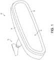
- FIG. 1is a perspective view of an interior rearview mirror assembly in accordance with the present invention
- FIG. 2is a cross-sectional view of a mirror reflective element with variable reflectance in accordance with the present invention
- FIG. 3is a schematic of a typical electrochromic drive circuit
- FIG. 4is a schematic of an electrochromic drive circuit in accordance with the present invention.
- FIG. 5is a block diagram of electrochromic drive and control system in accordance with the present invention.
- FIG. 6Ais a plan view of a typical electrochromic drive printed circuit board.
- FIG. 6Bis a plan view of an electrochromic drive printed circuit board in accordance with the present invention.
- an interior rearview mirror assembly 10 for a vehicleincludes a casing 12 and a reflective element 14 positioned at a front portion of the casing 12 ( FIG. 1 ).
- mirror assembly 10is configured to be adjustably mounted at an interior portion of a vehicle (such as to an interior or in-cabin surface of a vehicle windshield or a headliner of a vehicle or the like) via a mounting structure or mounting configuration or assembly 16 , where the mirror reflective element and mirror head may be adjusted by a driver of the vehicle to provide the driver with the desired view rearward of the vehicle.
- the mirror reflective element and electrochromic drive systemmay be implemented in an exterior rearview mirror assembly, where the base is mounted at a side portion of the vehicle and the mirror reflective element is adjusted relative to the base and the side portion of the vehicle, such as via an electrically powered actuator that is actuated or controlled via the driver of the vehicle.
- the mirror reflective elementcomprises a variable reflectance mirror reflective element that varies its reflectance responsive to electrical current applied to conductive coatings or layers of the reflective element.
- the mirror reflective element 14comprises a laminate construction variable reflectance electro-optic (such as electrochromic) reflective element assembly having a front substrate 18 and a rear substrate 20 with an electro-optic medium 22 (such as electrochromic (EC) medium) sandwiched therebetween and bounded by a perimeter seal 24 .
- electro-opticsuch as electrochromic
- front substrate 18has a front or first surface 18 a (the surface that generally faces the driver of a vehicle when the mirror assembly is normally mounted at the vehicle) and a rear or second surface 18 b opposite the front surface 18 a
- rear substrate 20has a front or third surface 20 a and a rear or fourth surface 20 b opposite the front surface 20 a
- the electro-optic medium 22disposed between the second surface 18 b and the third surface 20 a and bounded by the perimeter seal 24 of the reflective element (such as is known in the electrochromic mirror art).
- the second surface 18 ahas a transparent conductive coating 26 established thereat (such as an indium tin oxide (ITO) layer, or a doped tin oxide layer or any other transparent electrically semi-conductive layer or coating or the like (such as indium cerium oxide (ICO), indium tungsten oxide (IWO), or indium oxide (IO) layers or the like or a zinc oxide layer or coating, or a zinc oxide coating or the like doped with aluminum or other metallic materials, such as silver or gold or the like, or other oxides doped with a suitable metallic material or the like, or such as disclosed in U.S. Pat. No.
- ITOindium tin oxide
- ICOindium cerium oxide
- IWOindium tungsten oxide
- IOindium oxide
- aluminum or other metallic materialssuch as silver or gold or the like, or other oxides doped with a suitable metallic material or the like, or such as disclosed in U.S. Pat. No.
- the front or third surface 20 a of rear substrate 20may include one or more transparent semi-conductive layers (such as an ITO layer or the like), and one or more metallic electrically conductive layers (such as a layer of silver, aluminum, chromium or the like or an alloy thereof), and may include multiple layers such as disclosed in U.S. Pat. Nos. 7,274,501; 7,184,190 and/or 7,255,451, which are hereby incorporated herein by reference in their entireties.
- the mirror reflectormay comprise any suitable coatings or layers, such as a transflective coating or layer, such as described in U.S. Pat. Nos. 7,626,749; 7,274,501; 7,255,451; 7,195,381; 7,184,190; 6,690,268; 6,449,082; 5,140,455; 5,151,816; 6,178,034; 6,154,306; 6,002,511; 5,567,360; 5,525,264; 5,610,756; 5,406,414; 5,253,109; 5,076,673; 5,073,012; 5,066,112; 5,115,346; 5,724,187; 5,668,663; 5,910,854; 5,142,407 and/or 4,712,879, which are hereby incorporated herein by reference in their entireties, disposed at the front surface of the rear substrate (commonly referred to as the third surface of the reflective element) and opposing the electro-optic medium, such as an electrochromic medium disposed between
- the electrochromic reflective element or EC cellrequires precise power control in order to provide on-demand variable dimming.
- the EC cellrequires a control circuit or EC drive circuit that controls the EC cells responsive to, for example, an ambient light sensor and/or a glare light sensor (whereby, in nighttime driving conditions, the EC drive circuit dims or darkens the EC cell to reduce glare light at the mirror reflective element or cell when viewed by the driver of the vehicle).
- the ambient light sensormay be disposed anywhere at the vehicle (such as, for example, at the respective mirror assembly).
- the glare sensoris typically at or near the respective EC cell or mirror reflective element (such as behind the mirror reflective element and viewing/sensing through the mirror reflective element).
- the EC drive circuitapplies an appropriate or selected voltage at the electrically conductive coatings at the opposing surfaces of the glass substrate (that oppose and contact the EC medium) to cause an appropriate or selected degree of darkening of the EC cell to vary or attenuate reflectance off the mirror reflector (at the rear substrate and behind the EC medium) to reduce reflectance of light to the driver of the vehicle that is viewing the mirror assembly and EC cell.
- a typical control circuitincludes a “drive” transistor Q 1 and a “bleach” transistor Q 2 that are driven in complement.
- a pulse-width modulation (PWM) control signaladjusts the voltage provided to the EC cell by switching the transistors on and off. This causes a ripple voltage on each EC cell powered by the circuit.
- PWMpulse-width modulation
- the typical circuit of FIG. 3inefficiently dissipates power in three areas: in a regulator, in ballast resistors, and in the transistors. Further power is often wasted in stepping down the voltage from 5V or 8V to 1.2V. Often an inefficient linear regulator is used to generate the 5V or 8V supply (e.g., from the vehicle 12V supply), further increasing power losses. Additionally, due to saturation, the control voltage is limited by the bias voltage on the drive transistor.
- a switch mode power supply (SMPS) EC driving circuit 400is provided in accordance with the present invention.
- the circuit 400provides power to one or more EC cells through a fixed voltage switching regulator (e.g., 2V output) controlled by switch mode power supply controller U 1 .
- MOSFET Q 1metal-oxide-semiconductor field-effect transistor
- a bleach transistor Q 2may be a bipolar junction transistor (BJT). Protection diode D 1 shields MOSFET Q 1 from foreign or otherwise unwanted voltages.
- a feedback path(EC Cell Voltage Feedback) monitors the EC cell voltage and allows an EC controller (shown in FIG.
- the circuit 400minimizes cut through currents, as the EC controller drives the drive transistor Q 1 and the bleach transistor Q 2 independently. When the circuit 400 determines that dimming is not necessary, the EC controller can shut down the 2V output completely (through the SMPS Enable output), saving power.
- the EC controllerprovides a PWM input to the transistors Q 1 , Q 2 , allowing for rapid switching and high resolution EC cell voltage control. Further, the EC controller and the power supply controller U 1 provide short circuit and thermal protections via integrated safeguards.
- the circuit 400may use a variety of buck regulator integrated circuit (IC) devices depending on specific input voltage requirements.
- FIG. 5illustrates a block diagram of the previously described EC driving circuit 400 , demonstrating the EC controller (microcontroller) driving an enable input to the SMPS controller, and PWM inputs to the drive transistor and bleach transistor.
- the EC controllerreceives feedback from each individual EC cell (e.g., voltage, temperature, etc.), for example, an input EC cell (IEC) and an output EC cell (OEC).
- the SMPS controllermay receive a range in input voltage (e.g., the vehicle's 12V battery supply, which may typically range from 12.6V up to over 14.7V) and output the voltage required by the EC cells (e.g., 2V).
- the protection diodesensure unwanted voltages are not passed through the circuit.
- the circuit 400allows for an unregulated (e.g., from 4.5V to 36V) voltage input with significant efficiency increases over typical circuits. For example, a typical circuit is approximately 9 percent efficient, while the EC driving circuit 400 is greater than 50 percent efficient (e.g., 55 percent to 60 percent efficient or 57 percent to 60 percent efficient). This leads to a drastically reduced power draw (e.g., 0.2 W from circuit 400 instead of 1.4 W from a typical driving circuit). As shown in FIGS. 6A and 6B , the circuit 400 also allows for a significantly reduced printed circuit board (PCB) area. For example, a typical circuit ( FIG. 6A ) may require approximately 1000 mm 2 , while circuit 400 ( FIG. 6B ) may have a board area of approximately 300 mm 2 .
- PCBprinted circuit board
- the circuit 400 of the present inventionminimizes power losses through the use of a low resistance switch and low source voltage (e.g., 2V). This leads to a reduction in power dissipated and therefore a reduction in temperature.
- the PWM controlallows for fine adjustment of EC cell dimming. Dynamic feedback provides precise reporting of EC cell status, and the EC cell may be shut down completely if a fault is detected.
- the standby current that circuit 400 consumes while the EC cell is disabledis much lower than a typical driving circuit.
- a single switching regulatorcan drive two or more EC cells simultaneously with much less PCB area required. The switching regulator allows for stable operation over a wide range of input voltages and temperatures and may be fine-tuned with software to further increase performance under specific conditions or for specific applications. While the illustrated embodiment demonstrates an interior mirror, EC driving circuit 400 is suitable for any EC cell, including those found in exterior mirrors.
- the electro-optic or electrochromic mirror assemblyincludes an electro-optic or electrochromic reflective element that is dimmed or darkened via an EC drive circuit.
- the electrochromic mirror element of the electrochromic mirror assemblymay utilize the principles disclosed in commonly assigned U.S. Pat. Nos.
- the mirror assemblymay comprise any suitable construction, such as, for example, a mirror assembly with the reflective element being nested in the mirror casing and with a bezel portion that circumscribes a perimeter region of the front surface of the reflective element, or with the mirror casing having a curved or beveled perimeter edge around the reflective element and with no overlap onto the front surface of the reflective element (such as by utilizing aspects of the mirror assemblies described in U.S. Pat. Nos.
- the mirror assemblymay include user actuatable inputs operable to control any of the accessories of or associated with the mirror assembly and/or an accessory module or the like.
- the mirror assemblymay include touch sensitive elements or touch sensors or proximity sensors, such as the types of touch sensitive elements described in U.S. Pat. Nos. 5,594,222; 6,001,486; 6,310,611; 6,320,282; 6,627,918; 7,224,324 and/or 7,253,723, and/or U.S. Publication Nos. US-2014-0022390 and/or US-2014-0293169, which are hereby incorporated herein by reference in their entireties, or such as proximity sensors of the types described in U.S. Pat. Nos.
- the mirror assemblymay include one or more other displays, such as the types disclosed in U.S. Pat. Nos. 5,530,240 and/or 6,329,925, which are hereby incorporated herein by reference in their entireties, and/or display-on-demand transflective type displays, and/or video displays or display screens, such as the types disclosed in U.S. Pat. Nos.
Landscapes
- Physics & Mathematics (AREA)
- Nonlinear Science (AREA)
- Engineering & Computer Science (AREA)
- General Physics & Mathematics (AREA)
- Optics & Photonics (AREA)
- Chemical & Material Sciences (AREA)
- Crystallography & Structural Chemistry (AREA)
- Multimedia (AREA)
- Mechanical Engineering (AREA)
- Electrochromic Elements, Electrophoresis, Or Variable Reflection Or Absorption Elements (AREA)
Abstract
Description
Claims (20)
Priority Applications (1)
| Application Number | Priority Date | Filing Date | Title |
|---|---|---|---|
| US16/512,565US11292388B2 (en) | 2018-07-17 | 2019-07-16 | Electro-optic drive system for vehicular mirror |
Applications Claiming Priority (2)
| Application Number | Priority Date | Filing Date | Title |
|---|---|---|---|
| US201862699393P | 2018-07-17 | 2018-07-17 | |
| US16/512,565US11292388B2 (en) | 2018-07-17 | 2019-07-16 | Electro-optic drive system for vehicular mirror |
Publications (2)
| Publication Number | Publication Date |
|---|---|
| US20200023775A1 US20200023775A1 (en) | 2020-01-23 |
| US11292388B2true US11292388B2 (en) | 2022-04-05 |
Family
ID=69161469
Family Applications (1)
| Application Number | Title | Priority Date | Filing Date |
|---|---|---|---|
| US16/512,565Active2040-10-13US11292388B2 (en) | 2018-07-17 | 2019-07-16 | Electro-optic drive system for vehicular mirror |
Country Status (1)
| Country | Link |
|---|---|
| US (1) | US11292388B2 (en) |
Families Citing this family (1)
| Publication number | Priority date | Publication date | Assignee | Title |
|---|---|---|---|---|
| CN117693446A (en) | 2021-07-15 | 2024-03-12 | 金泰克斯公司 | Rearview assembly |
Citations (31)
| Publication number | Priority date | Publication date | Assignee | Title |
|---|---|---|---|---|
| US4712879A (en) | 1986-04-02 | 1987-12-15 | Donnelly Corporation | Electrochromic mirror |
| US5066112A (en) | 1989-12-21 | 1991-11-19 | Donnelly Corporation | Perimeter coated, electro-optic mirror |
| US5073012A (en) | 1988-02-12 | 1991-12-17 | Donnelly Corporation | Anti-scatter, ultraviolet protected, anti-misting, electro-optical assemblies |
| US5076673A (en) | 1990-08-10 | 1991-12-31 | Donnelly Corporation | Prolonged coloration electrochromic assembly |
| US5115346A (en) | 1988-02-12 | 1992-05-19 | Donnelly Corporation | Anti-scatter, ultraviolet protected, anti-misting, electro-optical rearview mirror |
| US5140455A (en) | 1989-11-29 | 1992-08-18 | Donnelly Corporation | High performance electrochemichromic solutions and devices thereof |
| US5142407A (en) | 1989-12-22 | 1992-08-25 | Donnelly Corporation | Method of reducing leakage current in electrochemichromic solutions and solutions based thereon |
| US5151816A (en) | 1989-12-29 | 1992-09-29 | Donnelly Corporation | Method for reducing current leakage and enhancing uv stability in electrochemichromic solutions and devices |
| US5253109A (en) | 1992-04-27 | 1993-10-12 | Donnelly Corporation | Electro-optic device with constant light transmitting area |
| US5525264A (en) | 1992-07-15 | 1996-06-11 | Donnelly Corporation | Precursor solutions for forming coatings |
| US5610756A (en) | 1990-11-26 | 1997-03-11 | Donnelly Corporation | Electrochromic mirror for vehicles |
| US5668663A (en) | 1994-05-05 | 1997-09-16 | Donnelly Corporation | Electrochromic mirrors and devices |
| US5910854A (en) | 1993-02-26 | 1999-06-08 | Donnelly Corporation | Electrochromic polymeric solid films, manufacturing electrochromic devices using such solid films, and processes for making such solid films and devices |
| US6002511A (en) | 1993-02-26 | 1999-12-14 | Donnelly Corporation | Electrochromic polymeric solid films, manufacturing electrochromic devices using such solid films, and processes for making such solid films and devices |
| US6178034B1 (en) | 1996-04-10 | 2001-01-23 | Donnelly Corporation | Electrochromic devices |
| US6449082B1 (en) | 1998-07-02 | 2002-09-10 | Donnelly Corporation | Busbars for electrically powered cells |
| US6690268B2 (en) | 2000-03-02 | 2004-02-10 | Donnelly Corporation | Video mirror systems incorporating an accessory module |
| US7184190B2 (en) | 2002-09-20 | 2007-02-27 | Donnelly Corporation | Electro-optic reflective element assembly |
| US7195381B2 (en) | 2001-01-23 | 2007-03-27 | Donnelly Corporation | Vehicle interior LED lighting system |
| US7215318B2 (en)* | 2002-06-24 | 2007-05-08 | Gentex Corporation | Electrochromic element drive control circuit |
| US7255451B2 (en) | 2002-09-20 | 2007-08-14 | Donnelly Corporation | Electro-optic mirror cell |
| US7274501B2 (en) | 2002-09-20 | 2007-09-25 | Donnelly Corporation | Mirror reflective element assembly |
| US7289037B2 (en) | 2003-05-19 | 2007-10-30 | Donnelly Corporation | Mirror assembly for vehicle |
| US7360932B2 (en) | 2004-06-01 | 2008-04-22 | Donnelly Corporation | Mirror assembly for vehicle |
| US7626749B2 (en) | 2005-05-16 | 2009-12-01 | Donnelly Corporation | Vehicle mirror assembly with indicia at reflective element |
| US8508831B2 (en) | 2009-04-23 | 2013-08-13 | Magna Mirrors Of America, Inc. | Mirror assembly for vehicle |
| US8730553B2 (en) | 2009-04-23 | 2014-05-20 | Magna Mirrors Of America, Inc. | Frameless interior rearview mirror assembly |
| US20140313563A1 (en) | 2013-04-22 | 2014-10-23 | Magna Mirrors Of America, Inc. | Interior rearview mirror assembly |
| US20150097955A1 (en) | 2010-02-10 | 2015-04-09 | Magna Mirrors Of America, Inc. | Exterior rearview mirror assembly |
| US9346403B2 (en) | 2009-10-07 | 2016-05-24 | Magna Mirrors Of America, Inc. | Rearview mirror assembly |
| US9598016B2 (en) | 2010-10-15 | 2017-03-21 | Magna Mirrors Of America, Inc. | Interior rearview mirror assembly |
- 2019
- 2019-07-16USUS16/512,565patent/US11292388B2/enactiveActive
Patent Citations (38)
| Publication number | Priority date | Publication date | Assignee | Title |
|---|---|---|---|---|
| US4712879A (en) | 1986-04-02 | 1987-12-15 | Donnelly Corporation | Electrochromic mirror |
| US5073012A (en) | 1988-02-12 | 1991-12-17 | Donnelly Corporation | Anti-scatter, ultraviolet protected, anti-misting, electro-optical assemblies |
| US5115346A (en) | 1988-02-12 | 1992-05-19 | Donnelly Corporation | Anti-scatter, ultraviolet protected, anti-misting, electro-optical rearview mirror |
| US5567360A (en) | 1989-11-29 | 1996-10-22 | Varaprasad; Desaraju V. | Electrochemichromic mirror |
| US5140455A (en) | 1989-11-29 | 1992-08-18 | Donnelly Corporation | High performance electrochemichromic solutions and devices thereof |
| US5066112A (en) | 1989-12-21 | 1991-11-19 | Donnelly Corporation | Perimeter coated, electro-optic mirror |
| US5142407A (en) | 1989-12-22 | 1992-08-25 | Donnelly Corporation | Method of reducing leakage current in electrochemichromic solutions and solutions based thereon |
| US5151816A (en) | 1989-12-29 | 1992-09-29 | Donnelly Corporation | Method for reducing current leakage and enhancing uv stability in electrochemichromic solutions and devices |
| US5076673A (en) | 1990-08-10 | 1991-12-31 | Donnelly Corporation | Prolonged coloration electrochromic assembly |
| US5610756A (en) | 1990-11-26 | 1997-03-11 | Donnelly Corporation | Electrochromic mirror for vehicles |
| US5406414A (en) | 1992-04-27 | 1995-04-11 | Donnelly Corporation | Electrochromic rearview mirror for vehicles with constant light transmitting area |
| US5253109A (en) | 1992-04-27 | 1993-10-12 | Donnelly Corporation | Electro-optic device with constant light transmitting area |
| US5525264A (en) | 1992-07-15 | 1996-06-11 | Donnelly Corporation | Precursor solutions for forming coatings |
| US5910854A (en) | 1993-02-26 | 1999-06-08 | Donnelly Corporation | Electrochromic polymeric solid films, manufacturing electrochromic devices using such solid films, and processes for making such solid films and devices |
| US6002511A (en) | 1993-02-26 | 1999-12-14 | Donnelly Corporation | Electrochromic polymeric solid films, manufacturing electrochromic devices using such solid films, and processes for making such solid films and devices |
| US6154306A (en) | 1993-02-26 | 2000-11-28 | Donnelly Corporation | Electrochromic polymeric solid films, manufacturing electrochromic devices using such solid films, and processes for making such solid films and devices |
| US5668663A (en) | 1994-05-05 | 1997-09-16 | Donnelly Corporation | Electrochromic mirrors and devices |
| US5724187A (en) | 1994-05-05 | 1998-03-03 | Donnelly Corporation | Electrochromic mirrors and devices |
| US6178034B1 (en) | 1996-04-10 | 2001-01-23 | Donnelly Corporation | Electrochromic devices |
| US6449082B1 (en) | 1998-07-02 | 2002-09-10 | Donnelly Corporation | Busbars for electrically powered cells |
| US6690268B2 (en) | 2000-03-02 | 2004-02-10 | Donnelly Corporation | Video mirror systems incorporating an accessory module |
| US7195381B2 (en) | 2001-01-23 | 2007-03-27 | Donnelly Corporation | Vehicle interior LED lighting system |
| US7215318B2 (en)* | 2002-06-24 | 2007-05-08 | Gentex Corporation | Electrochromic element drive control circuit |
| US8277059B2 (en) | 2002-09-20 | 2012-10-02 | Donnelly Corporation | Vehicular electrochromic interior rearview mirror assembly |
| US7184190B2 (en) | 2002-09-20 | 2007-02-27 | Donnelly Corporation | Electro-optic reflective element assembly |
| US7255451B2 (en) | 2002-09-20 | 2007-08-14 | Donnelly Corporation | Electro-optic mirror cell |
| US7274501B2 (en) | 2002-09-20 | 2007-09-25 | Donnelly Corporation | Mirror reflective element assembly |
| US8529108B2 (en) | 2002-09-20 | 2013-09-10 | Donnelly Corporation | Mirror assembly for vehicle |
| US7289037B2 (en) | 2003-05-19 | 2007-10-30 | Donnelly Corporation | Mirror assembly for vehicle |
| US8049640B2 (en) | 2003-05-19 | 2011-11-01 | Donnelly Corporation | Mirror assembly for vehicle |
| US7360932B2 (en) | 2004-06-01 | 2008-04-22 | Donnelly Corporation | Mirror assembly for vehicle |
| US7626749B2 (en) | 2005-05-16 | 2009-12-01 | Donnelly Corporation | Vehicle mirror assembly with indicia at reflective element |
| US8508831B2 (en) | 2009-04-23 | 2013-08-13 | Magna Mirrors Of America, Inc. | Mirror assembly for vehicle |
| US8730553B2 (en) | 2009-04-23 | 2014-05-20 | Magna Mirrors Of America, Inc. | Frameless interior rearview mirror assembly |
| US9346403B2 (en) | 2009-10-07 | 2016-05-24 | Magna Mirrors Of America, Inc. | Rearview mirror assembly |
| US20150097955A1 (en) | 2010-02-10 | 2015-04-09 | Magna Mirrors Of America, Inc. | Exterior rearview mirror assembly |
| US9598016B2 (en) | 2010-10-15 | 2017-03-21 | Magna Mirrors Of America, Inc. | Interior rearview mirror assembly |
| US20140313563A1 (en) | 2013-04-22 | 2014-10-23 | Magna Mirrors Of America, Inc. | Interior rearview mirror assembly |
Also Published As
| Publication number | Publication date |
|---|---|
| US20200023775A1 (en) | 2020-01-23 |
Similar Documents
| Publication | Publication Date | Title |
|---|---|---|
| US7215318B2 (en) | Electrochromic element drive control circuit | |
| US12240384B2 (en) | Interior rearview mirror assembly with full screen video display | |
| US7535614B1 (en) | Electrical window control system and method thereof | |
| KR101463801B1 (en) | Variable transmission window system | |
| US8017896B2 (en) | Vehicle accessory having a rear light receiving sensor for measuring illumination intensity inside the vehicle | |
| JP6782682B2 (en) | Electro-optic mirror system and its method | |
| US6595649B2 (en) | Digital electrochromic mirror system | |
| EP0146672A1 (en) | Drive apparatus for a liquid crystal dazzle free mirror arrangement | |
| JPS60169347A (en) | Drive device for antiglaring mirror for vehicle | |
| JP2015527948A (en) | Sunroof including lighting means | |
| CN201273979Y (en) | Electrochromic lens and antiglare device | |
| US11292388B2 (en) | Electro-optic drive system for vehicular mirror | |
| US20090244707A1 (en) | Vehicle accessory | |
| WO2013132904A1 (en) | Electronic device and spacer with metal thin film | |
| JP2002234391A (en) | Anti-glare mirror device mounted in car | |
| JP3467409B2 (en) | Drive device for EC panel for rearview mirror | |
| KR20240148753A (en) | Smart Sun Visor Apparatus Using Film Type Smart Glass | |
| WO2025191448A1 (en) | Rearview mirror heater assembly | |
| US20250074309A1 (en) | Vehicular interior rearview mirror assembly with electrification of electrochromic mirror | |
| CN223284481U (en) | Anti-glare rearview mirror lens and anti-glare rearview mirror | |
| CN110389462A (en) | Photochromic films | |
| JPH07215057A (en) | Solar radiation control device for vehicle | |
| US4931706A (en) | Electrical circuit for protecting a power supply connected to apply signals to a retractable sunroof containing materials that respond to an applied electrical signal | |
| US11921281B2 (en) | Attachment device for an eyepiece or an objective lens of a long-range optical device | |
| JP2996457B2 (en) | Anti-glare mirror device for vehicles |
Legal Events
| Date | Code | Title | Description |
|---|---|---|---|
| FEPP | Fee payment procedure | Free format text:ENTITY STATUS SET TO UNDISCOUNTED (ORIGINAL EVENT CODE: BIG.); ENTITY STATUS OF PATENT OWNER: LARGE ENTITY | |
| STPP | Information on status: patent application and granting procedure in general | Free format text:APPLICATION DISPATCHED FROM PREEXAM, NOT YET DOCKETED | |
| STPP | Information on status: patent application and granting procedure in general | Free format text:DOCKETED NEW CASE - READY FOR EXAMINATION | |
| STPP | Information on status: patent application and granting procedure in general | Free format text:NOTICE OF ALLOWANCE MAILED -- APPLICATION RECEIVED IN OFFICE OF PUBLICATIONS | |
| AS | Assignment | Owner name:MAGNA MIRRORS OF AMERICA, INC., MICHIGAN Free format text:ASSIGNMENT OF ASSIGNORS INTEREST;ASSIGNORS:PETERSON, ERIC;KOETJE, CHRISTOPHER R.;REEL/FRAME:058397/0466 Effective date:20190820 | |
| STPP | Information on status: patent application and granting procedure in general | Free format text:AWAITING TC RESP., ISSUE FEE NOT PAID | |
| STPP | Information on status: patent application and granting procedure in general | Free format text:NOTICE OF ALLOWANCE MAILED -- APPLICATION RECEIVED IN OFFICE OF PUBLICATIONS | |
| STPP | Information on status: patent application and granting procedure in general | Free format text:PUBLICATIONS -- ISSUE FEE PAYMENT RECEIVED | |
| STPP | Information on status: patent application and granting procedure in general | Free format text:PUBLICATIONS -- ISSUE FEE PAYMENT VERIFIED | |
| STCF | Information on status: patent grant | Free format text:PATENTED CASE | |
| MAFP | Maintenance fee payment | Free format text:PAYMENT OF MAINTENANCE FEE, 4TH YEAR, LARGE ENTITY (ORIGINAL EVENT CODE: M1551); ENTITY STATUS OF PATENT OWNER: LARGE ENTITY Year of fee payment:4 |