US11291573B2 - Delivery system for a self-expanding medical device - Google Patents
Delivery system for a self-expanding medical deviceDownload PDFInfo
- Publication number
- US11291573B2 US11291573B2US14/209,097US201414209097AUS11291573B2US 11291573 B2US11291573 B2US 11291573B2US 201414209097 AUS201414209097 AUS 201414209097AUS 11291573 B2US11291573 B2US 11291573B2
- Authority
- US
- United States
- Prior art keywords
- medical device
- sheath
- restraining sheath
- restraining
- inner catheter
- Prior art date
- Legal status (The legal status is an assumption and is not a legal conclusion. Google has not performed a legal analysis and makes no representation as to the accuracy of the status listed.)
- Active, expires
Links
Images


Classifications
- A—HUMAN NECESSITIES
- A61—MEDICAL OR VETERINARY SCIENCE; HYGIENE
- A61F—FILTERS IMPLANTABLE INTO BLOOD VESSELS; PROSTHESES; DEVICES PROVIDING PATENCY TO, OR PREVENTING COLLAPSING OF, TUBULAR STRUCTURES OF THE BODY, e.g. STENTS; ORTHOPAEDIC, NURSING OR CONTRACEPTIVE DEVICES; FOMENTATION; TREATMENT OR PROTECTION OF EYES OR EARS; BANDAGES, DRESSINGS OR ABSORBENT PADS; FIRST-AID KITS
- A61F2/00—Filters implantable into blood vessels; Prostheses, i.e. artificial substitutes or replacements for parts of the body; Appliances for connecting them with the body; Devices providing patency to, or preventing collapsing of, tubular structures of the body, e.g. stents
- A61F2/95—Instruments specially adapted for placement or removal of stents or stent-grafts
- A61F2/962—Instruments specially adapted for placement or removal of stents or stent-grafts having an outer sleeve
- A61F2/966—Instruments specially adapted for placement or removal of stents or stent-grafts having an outer sleeve with relative longitudinal movement between outer sleeve and prosthesis, e.g. using a push rod
- A—HUMAN NECESSITIES
- A61—MEDICAL OR VETERINARY SCIENCE; HYGIENE
- A61F—FILTERS IMPLANTABLE INTO BLOOD VESSELS; PROSTHESES; DEVICES PROVIDING PATENCY TO, OR PREVENTING COLLAPSING OF, TUBULAR STRUCTURES OF THE BODY, e.g. STENTS; ORTHOPAEDIC, NURSING OR CONTRACEPTIVE DEVICES; FOMENTATION; TREATMENT OR PROTECTION OF EYES OR EARS; BANDAGES, DRESSINGS OR ABSORBENT PADS; FIRST-AID KITS
- A61F2/00—Filters implantable into blood vessels; Prostheses, i.e. artificial substitutes or replacements for parts of the body; Appliances for connecting them with the body; Devices providing patency to, or preventing collapsing of, tubular structures of the body, e.g. stents
- A61F2/95—Instruments specially adapted for placement or removal of stents or stent-grafts
- A61F2/9517—Instruments specially adapted for placement or removal of stents or stent-grafts handle assemblies therefor
- A—HUMAN NECESSITIES
- A61—MEDICAL OR VETERINARY SCIENCE; HYGIENE
- A61F—FILTERS IMPLANTABLE INTO BLOOD VESSELS; PROSTHESES; DEVICES PROVIDING PATENCY TO, OR PREVENTING COLLAPSING OF, TUBULAR STRUCTURES OF THE BODY, e.g. STENTS; ORTHOPAEDIC, NURSING OR CONTRACEPTIVE DEVICES; FOMENTATION; TREATMENT OR PROTECTION OF EYES OR EARS; BANDAGES, DRESSINGS OR ABSORBENT PADS; FIRST-AID KITS
- A61F2/00—Filters implantable into blood vessels; Prostheses, i.e. artificial substitutes or replacements for parts of the body; Appliances for connecting them with the body; Devices providing patency to, or preventing collapsing of, tubular structures of the body, e.g. stents
- A61F2/95—Instruments specially adapted for placement or removal of stents or stent-grafts
- A61F2/9522—Means for mounting a stent or stent-graft onto or into a placement instrument
- A—HUMAN NECESSITIES
- A61—MEDICAL OR VETERINARY SCIENCE; HYGIENE
- A61F—FILTERS IMPLANTABLE INTO BLOOD VESSELS; PROSTHESES; DEVICES PROVIDING PATENCY TO, OR PREVENTING COLLAPSING OF, TUBULAR STRUCTURES OF THE BODY, e.g. STENTS; ORTHOPAEDIC, NURSING OR CONTRACEPTIVE DEVICES; FOMENTATION; TREATMENT OR PROTECTION OF EYES OR EARS; BANDAGES, DRESSINGS OR ABSORBENT PADS; FIRST-AID KITS
- A61F2/00—Filters implantable into blood vessels; Prostheses, i.e. artificial substitutes or replacements for parts of the body; Appliances for connecting them with the body; Devices providing patency to, or preventing collapsing of, tubular structures of the body, e.g. stents
- A61F2/95—Instruments specially adapted for placement or removal of stents or stent-grafts
- A61F2002/9505—Instruments specially adapted for placement or removal of stents or stent-grafts having retaining means other than an outer sleeve, e.g. male-female connector between stent and instrument
Definitions
- the present inventionrelates generally to medical devices and more particularly to delivery systems for medical devices.
- Intraluminal medical devicesare used by physicians to treat numerous conditions using minimally invasive procedures.
- Examples of intraluminal medical devicesinclude stents, stent-grafts, filters, valves, etc.
- One type of intraluminal medical device that has become especially commonis self-expanding stents.
- self-expanding medical devicesincluding stents, are made from an elastic structure that may be compressed into a low profile state that can be passed through vessels in a patient with minimal trauma. Once at the desired treatment site, the self-expanding medical device is released and self-expands like a spring until it contacts a tissue wall which prevents further expansion.
- Common materials that are used in self-expanding medical devicesinclude nitinol and stainless steel, although other materials are also possible.
- Self-expanding stentsare used to treat various organs, such as the vascular system, colon, biliary tract, urinary tract, esophagus, trachea and the like.
- stentsare commonly used to treat blockages, occlusions, narrowing ailments and other similar problems that restrict flow through a passageway.
- One area where stents are commonly used for treatmentinvolves implanting an endovascular stent into the vascular system in order to improve or maintain blood flow through narrowed arteries.
- stentsare also used in other treatments as well, such as the treatment of aneurysms.
- Stentshave been shown to be useful in treating various vessels throughout the vascular system, including both coronary vessels and peripheral vessels (e.g., carotid, brachial, renal, iliac and femoral). In addition, stents have been used in other body vessels as well, such as the digestive tract.
- One type of delivery system for intraluminal medical devicesincludes an inner catheter and an outer sheath attached to a handle arrangement.
- One portion of the handleis typically connected to the inner catheter and another portion of the handle is typically connected to the outer sheath.
- the inner catheterextends coaxially through the outer sheath, and the two portions of the handle are arranged to longitudinally pull the outer sheath relative to the inner catheter.
- the outer sheathalso serves to radially restrain the device in the compressed state until the outer sheath is withdrawn.
- the medical deviceis released in the body at the treatment site, and in the case of a self-expanding stent, the stent expands outward away from the inner catheter and presses against the vessel wall.
- the outer sheathis usually withdrawn by pulling the outer sheath proximally relative to the inner catheter, it may also be possible to withdraw the outer sheath by pushing the inner catheter distally relative to the outer sheath.
- the handlemay then be pulled by the physician to withdraw the inner catheter and outer sheath from the patient's body, while leaving the medical device implanted in the body.
- Precise placement of intraluminal medical devicesis a concern in most medical procedures.
- One problem that can contribute to imprecise placement of intraluminal medical devicesis deflection of the delivery system during deployment. This can be a particular problem in the deployment of self-expanding medical devices, like stents, because the medical device presses outward against the inner surface of the outer sheath prior to deployment. When the outer sheath is withdrawn, the outward pressure exerted by the medical device creates friction between the medical device and the outer sheath.
- the frictional force between the medical device and the outer sheathcauses the outer sheath to be in tension and the inner catheter to be in compression. This can cause the outer sheath to stretch in length due to the tensile force.
- the force required to withdraw the outer sheathcan be especially high. As a result, it can be difficult for a physician to accurately control deployment of the medical device.
- a delivery systemfor self-expanding medical devices.
- the delivery systemhas an inner catheter with a stop surface that extends from the proximal end of the medical device to a deployment handle.
- a restraining sheathsurrounds the medical device and prevents the medical device from expanding prior to deployment.
- the proximal end of the restraining sheathterminates distally from the deployment handle.
- a wireis adhered to the restraining sheath and extends from the restraining sheath to the deployment handle.
- the medical deviceis deployed by pulling on the wire which causes the restraining sheath to withdraw proximally from the medical device.
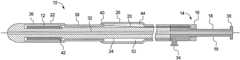
- FIG. 1is a cross-sectional view of a delivery system
- FIG. 2is a cross-sectional view of a portion of a restraining sheath
- FIG. 3is a side view of a wire
- FIG. 4is a cross-sectional view of a portion of another restraining sheath
- FIG. 5is a side view of another wire
- FIG. 6is a cross-sectional view of a portion of another restraining sheath
- FIG. 7is a side view of wires with interleaved coiled portions and coiled wires
- FIG. 8is a cross-sectional view of a covering sheath
- FIG. 9is a perspective view of another delivery system, showing a covering sheath
- FIG. 10is a perspective view of the delivery system, showing a restraining sheath, wires, a spacer tube and an inner catheter;
- FIG. 11is an enlarged perspective view of area A from FIG. 9 , showing a joint between the spacer tube and the inner catheter;
- FIG. 12is a perspective view of the delivery system, showing the restraining sheath withdrawn
- FIG. 13is an enlarged perspective view of area B from FIG. 11 , showing the wires extending from the proximal end of the inner catheter;
- FIG. 14is a perspective view of the spacer tube and the inner catheter
- FIG. 15is a perspective view of the inner catheter
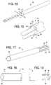
- FIG. 16is an enlarged perspective view of area C from FIG. 14 ;
- FIG. 17is a perspective view of the restraining sheath and the wires
- FIG. 18is a perspective view of the distal end of the spacer tube
- FIG. 19is a perspective view of the proximal end of the spacer tube
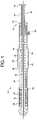
- FIG. 20is a cross-sectional view of another delivery system
- FIG. 21is a perspective view of the delivery system
- FIG. 22is a perspective view of a portion of the delivery system, showing the inner catheter and the wires extending through open passageways;
- FIG. 23is a cross-sectional view of the delivery system.
- the delivery system 10includes a deployment handle 14 with first and second handle members 16 , 18 .
- the first handle member 16is attached to a wire 20 connected to a restraining sheath 22
- the second handle member 18is attached to an inner catheter 24 .
- a covering sheath 26is also attached to the second handle member 18 .
- the deployment handle 14may also have a guide section 28 to control proximal movement of the first handle member 16 and a proximal stop 30 to limit proximal travel of the first handle member 16 .
- the delivery system 10may be used with numerous types of deployment handles including deployment handles that wind up the wire 20 during deployment.
- the delivery system 10is preferably an over-the-wire system where the guide wire lumen 37 extends from the distal end of the inner catheter 24 to the deployment handle 14 .
- the deployment handle 14is also preferably provided with a flushing port 34 that is in communication with the annular space between the covering sheath 26 and the inner catheter 24 and between the restraining sheath 22 and the inner catheter 24 .
- a self-expanding stent 12 made from nitinolis one preferred type of medical device 12 that may be used.
- the restraining sheath 22may have a first portion 36 that extends along the length of the stent 12 and a second portion 38 that extends proximally from the proximal end of the stent 12 .
- the first portion 36is sized to circumferentially restrain the stent 12 in a compressed state and prevent the stent 12 from expanding until the restraining sheath 22 is withdrawn from the stent 12 by pulling the wires 20 .
- the second portion 38is no longer than about 2 times the length of the stent 12 .
- the second portion 38 of the restraining sheath 22may have a smaller outer profile compared to the first portion 36 .
- the second portion 38is preferably at least as long as the stent 12 so that the second portion 38 has enough length to slide through the covering sheath 26 without the first portion 36 sliding into the covering sheath 26 during deployment.
- the entire length of the restraining sheath 22may have a generally constant profile.
- the restraining sheath 22may also terminate near the proximal end of the stent 12 if desired.
- the covering sheath 26is preferably fixed to the deployment handle 14 and does not move during deployment of the stent 12 .
- the covering sheath 26may be desirable to contain the wires 20 and provide an annular lumen to direct flushing fluid from the flushing port 34 through the delivery system 10 .
- the covering sheath 26may also provide additional robustness to the delivery system 10 .
- the distal end of the covering sheath 26extends over at least the proximal end of the restraining sheath 22 . However, it is preferred that the covering sheath 26 not extend over the portion of the restraining sheath 22 that encompasses the stent 12 .
- the distal end of the covering sheath 26preferably extends over only the portion of the restraining sheath 22 that extends proximally from the proximal end of the stent 12 .
- the distal end of the covering sheath 26may be provided with an atraumatic tapered end 40 that provides a smooth transition between the restraining sheath 22 and the covering sheath 26 .
- the distal end of the covering sheath 26may also be provided with an inner diameter that fits closely onto the outer diameter of the restraining sheath 22 to present a smooth transition and to minimize leakage of flushing fluid between the restraining sheath 22 and the covering sheath 26 .
- the inner catheter 24has a stop surface 42 that abuts the proximal end of the stent 12 during deployment to prevent the stent 12 from moving proximally during deployment.
- the stop surface 42may be a metal or polymer ring bonded to the inner catheter 24 or may be an integral step on the inner catheter 24 .
- the proximal end of the restraining sheath 22terminates distally from the deployment handle 14 so that the deployment handle 14 and the restraining sheath 22 are separated by a longitudinal space 44 .
- the longitudinal space 44must be at least as long as the longest stent 12 used in the delivery system 10 to allow enough travel to withdraw the restraining sheath 22 from the stent 12 .
- One or more wires 20are attached to the restraining sheath 22 that extend across the space 44 between the restraining sheath 22 and the deployment handle 14 .
- multiple wires 20are used that are equally spaced circumferentially around the inner catheter 24 .
- the proximal end of the wires 20may be attached to the first handle member 16 or any type of mechanism designed to pull the wires 20 .
- the stent 12may be deployed by pulling on the wires 20 to proximally withdraw the restraining sheath 22 away from the stent 12 .
- the stop surface 42prevents the stent 12 from moving proximally with the restraining sheath 22 , the restraining sheath 22 uncovers the stent 12 as it moves proximally. As a result, the stent 12 is allowed to self-expand toward a vessel wall and radially away from the inner catheter 24 .
- the wire 20may have a coiled portion 46 and a straight portion 48 .
- the coiled portion 46is adhered to the restraining sheath 22 to fix the wire 20 and restraining sheath 22 together.
- the restraining sheath 22may be made out of a thermoplastic polymer 50 like nylon, and the coiled portion 46 may be embedded within the thermoplastic polymer 50 like in FIG. 2 so that the thermoplastic polymer 50 covers the coiled portion 46 .
- the attachment of the coiled portion 46 to the restraining sheath 22provides a stronger connection between the restraining sheath 22 and the wire 20 compared to if the restraining sheath 22 and a wire 20 were only attached along the straight portion 46 of the wire 20 .
- the wire 20bends away from the helical path of the coiled portion 46 and extends generally parallel to the axis of the coiled portion 46 .
- the transition between the coiled portion 46 and the straight portion 48is located distal from the proximal end of the restraining sheath 22 , although a part of the coiled portion 46 could extend proximally from the proximal end of the restraining sheath 22 .
- the straight portion 48extends proximally from the restraining sheath 22 , and as shown in FIG. 1 , the straight portion 48 extends across the space 44 between the restraining sheath 22 and the deployment handle 14 and through the annular space 52 between the covering sheath 26 and the inner catheter 24 .
- the wire 20may have various cross-sectional shapes, such as rectangular, the cross-section of the wire is preferably round.
- the coiled portion 46 of the wire 20may have a single coiled diameter and may extend only along the second portion 38 of the restraining sheath 22 where the second portion 38 is smaller in diameter than the first portion 36 like FIG. 1 .
- a single diameter coiled portion 46 like in FIGS. 2-3may extend along a part of the first portion 36 of the restraining sheath 22 .
- the coiled portion 46 of the wire 20could extend along at least half the length of the stent 12 or along the entire length of the stent 12 .
- the coiled portion 46 of the wire 20may have a first section 54 with a coiled diameter that is larger than the coiled diameter of the second section 56 .
- This arrangementmay be useful with the restraining sheath 22 of FIG. 1 , where the first portion 36 has inner and outer circumferences that are larger than the inner and outer circumferences of the second portion 38 .
- the first section 54 of the coiled portion 46may extend along a portion of the length of the stent 12
- the second section 56may extend proximally from the stent 12 .
- the first section 54may extend along at least half the length of the stent 12 or along the entire length of the stent 12 .
- multiple wires 20may be adhered to the restraining sheath 22 .
- the coiled portions 46 of the wires 20may be spaced away from each other so that the coiled portions 46 fit within each other without interfering.
- the coiled portions 46may also be oriented relative to each other so that the straight portions 48 are circumferentially spaced around the inner catheter 24 . As also shown FIGS.
- coiled wires 58 that do not extend proximally to the deployment handle 14may also be spaced between the coiled portions 46 .
- the coiled wires 58may only be coiled without having a straight portion.
- the coiled wires 58may also terminate where the wires 20 transition between the coiled portion 46 and the straight portion 48 or distally from the transition.
- thermoplastic polymer 50it may be possible in this embodiment for the thermoplastic polymer 50 to only cover the coiled portions 46 and the coiled wires 58 without being disposed along the inner surface of the coiled portions 46 and coiled wires 58 . This may be desirable to reduce the profile of the restraining sheath 22 .
- a low friction liner 60such as polytetrafluoroethylene (PTFE), may also be disposed along the inner surface of at least the first portion 36 of the restraining sheath 22 that extends along the stent 12 . This may be useful to reduce the friction between the restraining sheath 22 and the stent 12 to lower the force required to withdraw the restraining sheath 22 . For example, as shown in FIG.
- the coiled portions 46 of the wires 20 and the coiled wires 58 without a straight portionmay extend only along the second portion 38 of the restraining sheath 22 proximally from the stent 12 .
- the liner 60may then extend along the length of the stent 12 and contact the outer surface of the stent 12 .
- the thermoplastic polymer 50may cover the coiled portions 46 of the wires 20 , the coiled wires 58 and the liner 60 to adhere all of the components together.
- the embodiment of FIG. 6may be used with a restraining sheath 22 like FIG. 1 with a larger first portion 36 and smaller second portion 38 , or may also be used with a restraining sheath 22 like FIGS. 10 and 20 where the restraining sheath 22 has a constant circumference along its length.
- the covering sheath 26may also be desirable to provide the covering sheath 26 with a coiled wire 62 embedded within a thermoplastic polymer 64 . This may be useful to strengthen the covering sheath 26 to minimize buckling of the inner catheter 24 within the covering sheath 26 .
- FIGS. 9-19Another embodiment of the delivery system 66 is shown in FIGS. 9-19 .
- FIGS. 9-19Another embodiment of the delivery system 66 is shown in FIGS. 9-19 .
- features of the delivery system 10that have been described above are not repeated below, since one of ordinary skill in the art will understand that the principles described above could be used with different types of delivered delivery systems including the delivery systems 66 , 90 of FIGS. 9-19 and 20-23 .
- One advantage of the delivery systems 66 , 90 of FIGS. 9-19 and 20-23is that they may be used with a family of medical devices 12 that have different lengths while minimizing the number of components that must be changed to accommodate different length medical devices 12 .
- a universal deployment handle 14that can pull the wires 20 different lengths depending on the length of the stent 12 that is used, such as a handle that winds up the wire 20
- a common deployment handle 14may also be used.
- FIG. 9shows the delivery system 66 with a covering sheath 26 that extends over the proximal end of the restraining sheath 22 and extends proximally to the deployment handle 14 where it is fixed to the deployment handle like in FIG. 1 .
- the covering sheath 26does not move during deployment of the stent 12 .
- the covering sheath 26preferably does not extend over any part of the restraining sheath 22 that covers the stent 12 .
- the covering sheath 26in this case should only extend over the portion of the restraining sheath 22 located proximally from the stent 12 so that the covering sheath 26 does not interfere with expansion of the stent 12 when the restraining sheath 22 is withdrawn. It is also preferable for the covering sheath 26 and the restraining sheath 22 (illustrated in FIG. 10 ) to have inner and outer circumferences that are generally constant along the entire length of the covering sheath 26 and restraining sheath 22 . This allows the length of the restraining sheath 22 to be shorter in length relative to a restraining sheath 22 like FIG.
- the proximal end of the restraining sheath 22can be closer to the proximal end of the stent 12 .
- the restraining sheath 22it may be preferable for the restraining sheath 22 to be about 1.5 times or less as long as the longest stent 12 in the family of stents 12 .
- the restraining sheath 22must be at least as long as the longest stent 12 in the family and longer than the shortest stent 12 in the family in order to use a common restraining sheath 22 in the delivery system 66 , 90 .
- the length of the restraining sheath 22extends from the distal end of the stent 12 and terminates distally from the deployment handle 14 and prevents the stent 12 from self-expanding prior to deployment.
- the wire 20is adhered to the restraining sheath 22 and extends from the proximal end of the restraining sheath 22 to the deployment handle 14 .
- the longitudinal space between the restraining sheath 22 and the deployment handle 14must be at least as long as the longest stent 12 in the family to allow enough space for the restraining sheath 22 to be withdrawn from the stent 12 .
- the stent 12is deployed by pulling the wires 20 proximally to withdraw the restraining sheath 22 .
- the inner catheter 24has a distal-facing end 68 that either directly forms a stop surface 68 or supports a stop surface 68 , such as a metal or polymer ring.
- the stop surface 68abuts the proximal end of the stent 12 to prevent the stent 12 from moving proximally as the restraining sheath 22 is withdrawn.
- the distal-facing end 68 that forms or supports the stop surface 68may be trimmed during manufacturing based on the length of each stent 12 .
- the end 68 of the inner catheter 24is trimmed so that when the proximal end of each stent 12 abuts the stop surface 68 , the distal end of each stent 12 in the family is positioned at the same general position regardless of the length of each stent 12 .
- thismay be done by providing the inner catheter body 70 with a step 72 and providing a tube 74 that slides over the distal portion of the inner catheter body 70 until the proximal end 76 of the tube 74 abuts the step 72 .
- the step 72may be located at a common position so that the same inner catheter body 70 can be used for all delivery systems 66 in the family.
- the inner catheter 24is thus trimmed to length by trimming the distal end 78 of the tube 74 to the appropriate length.
- the distal end 78 of the tube 74forms or supports the stop surface 68 for the stent 12 .
- the tube 74is made from plastic, such as polyether ether ketone (PEEK), and is preferably at least 5 mm long even when trimmed for the longest stent 12 in the family.
- PEEKpolyether ether ketone
- the wires 20may also be desirable for the wires 20 to extend through corresponding passageways 80 in the inner catheter 24 along a majority of the length between the deployment handle 14 and the restraining sheath 22 . This may be desirable to ensure that the wires 20 stay separated from each other and do not get entangled with each other or interfere with each other when the restraining sheath 22 is withdrawn.
- the delivery system 66 , 90may curve around various bends in the anatomy, and without the wires 20 being restrained and separated from each other, the wires 20 would tend to pull toward the inner side of the curve.
- a restraining sheath 22 with a single wire 20may benefit from having the wire 20 extend through a passageway 80 , 104 in the inner catheter 24 , passageways 80 , 104 for the wires 20 may be especially useful where two or more wires 20 are used to keep the wires 20 separated from each other as explained. While a single wire 20 may be used for the delivery system 10 , 66 , 90 , in most cases two or more wires 20 will be used to balance the withdrawing force around the circumference of the restraining sheath 22 .
- each passageway 80may be closed. That is, each passageway 80 fully encloses the circumference of each wire 20 along a portion of the length between the restraining sheath 22 and the deployment handle 14 .
- the passageways 104may also be open, such that at least part of the outer side of each wire 20 is uncovered by the passageway 104 .
- each of the wires 20may be unenclosed along a first length 82 proximal from the restraining sheath 22 .
- the first unenclosed length 82will typically be at least as long as the stent 12 being delivered to allow the restraining sheath 22 to be fully withdrawn from the stent 12 .
- the first length 82may be about 2 times the length of the stent 12 being delivered or less.
- the wires 20are preferably enclosed within corresponding passageways 80 along a second length 84 proximal from the first length 82 .
- the second length 84may be a majority of the length between the deployment handle 14 and the restraining sheath 22 , or may be the entire length between the deployment handle 14 and the first length 82 .
- the wires 20may enter the passageways 80 through distal openings 86 formed through the step 72 on the inner catheter 24 .
- the wires 20may angle inward from the retention sheath 22 along the first length 82 to enter the passageways 80 .
- the proximal end 76 of the tube 74may be provided with recesses 88 to allow the wires 20 to extend through the recesses 88 to enter the passageways 80 .
- the recesses 88may be aligned with the distal openings 86 of the passageways 80 by inserting positioning mandrels through the distal openings 86 before the tube 74 is slid onto the inner catheter body 70 .
- each positioning mandrelwill guide the recesses 88 to line up the recesses 88 and the passageways 80 . It may also be preferable to bond the tube 74 to the inner catheter body 70 at the proximal end 76 of the tube 74 and at the step 72 on the inner catheter body 70 . This may be done by applying adhesive to the proximal end 76 of the tube 74 and the step 72 as the tube 74 is slid onto the inner catheter body 70 . The positioning mandrels also may prevent the adhesive from entering the passageways 80 during bonding.
- the step 72 on the inner catheter body 70may also be formed by various methods, but centerless grinding may be a preferred method. Where the step 72 is formed by centerless grinding, the step 72 may have a slight taper as shown in FIG. 16 , and the proximal end 76 of the tube 74 may be provided with a corresponding inward taper.
- PEEKpolyether ether ketone
- FIGS. 20-23Another embodiment of the delivery system 90 is shown in FIGS. 20-23 .
- the end 92 of the inner catheter 24 which is trimmed to accommodate stents 12 of different lengthsmay be integral with the length of the inner catheter 24 that forms the inner catheter body 94 .
- the very end 92 of the inner catheter body 94could be the end 92 that supports or forms the stop surface 92 .
- the inner catheter body 94itself may be trimmed to length depending on the length of the stent 12 being loaded into the delivery system 90 .
- the inner catheter body 94may be made from polyether ether ketone (PEEK), since the trimmed end 92 may be durable enough to form the stop surface 92 without requiring a separate metal or polymer ring for the stop surface 92 .
- the portion of the inner catheter 24 that extends through the stent 12 and is attached to the atraumatic tip 96may be a separate liner 98 that extends through the lumen of the inner catheter body 94 and extends distally past the stop surface 92 to the atraumatic tip 96 .
- the liner 98extends proximally to the deployment handle 14 and is fixed to the inner catheter body 94 at the deployment handle 14 .
- the liner 98forms the guidewire lumen 32
- a lubricious liner 98may be used, such as polytetrafluoroethylene (PTFE).
- PTFEpolytetrafluoroethylene
- the liner 98may be bonded along the length of the inner catheter body 94
- the liner 98may also float unattached within the lumen of the inner catheter body 94 and may be attached to the inner catheter body 94 at the deployment handle 14 .
- the tip 96may be located closer to the proximal end of the stent 12 without needing to leave extra space at the distal end as is conventionally done during manufacturing when gluing the tip 96 onto the inner catheter 24 .
- the tip 96may be glued to the distal end of the liner 98 before the liner 98 is positioned within the lumen of the inner catheter body 94 .
- the liner 98may then be inserted into the central lumen of the inner catheter body 94 after the stent 12 is loaded into the restraining sheath 22 , and the stent 12 and restraining sheath 22 are positioned on the inner catheter body 94 .
- This allows the tip 96which will form the leading end of the delivery system 90 , to be positioned next to the distal end of the stent 12 after the tip 96 has been attached to the liner 98 .
- the manufacturing assemblerdoes not need to leave extra space to provide access for gluing and to prevent wet adhesive from contacting the stent 12 .
- the delivery system 90 shown in FIGS. 20-21may have a restraining sheath 22 with inner and outer circumferences that are generally constant along the entire length of the restraining sheath 22 .
- the second portion of the restraining sheath 38 that extends proximally from the proximal end of the stent 12may be shorter than the length of the stent 12 and may be shorter than the first portion 36 of the restraining sheath 22 which extends along the length of the stent 12 .
- thisallows the covering sheath 26 shown in FIGS. 20-21 to also have inner and outer circumferences that are constant along the entire length of the covering sheath 26 .
- the inner catheter 24may be provided with a first outer circumference 100 that extends proximally from the stop surface 92 along a length at least as long as the length of the stent 12 .
- the inner catheter 24may also have a second outer circumference 102 extending proximally from the first outer circumference 100 along a length that is at least a majority of the length between the deployment handle 14 and the first outer circumference 100 .
- the second outer circumference 102extends along the entire length from the deployment handle 14 to the first outer circumference 100 .
- the second outer circumference 102may be larger than the first outer circumference 100 .
- the first outer circumference 100is sized to be smaller than the inner circumference of the restraining sheath 22 so that the restraining sheath 22 can slide proximally over the first outer circumference 100 of the inner catheter 24 .
- the second outer circumference 102may be sized larger than the inner circumference of the restraining sheath 22 since the restraining sheath 22 only needs to be withdrawn a sufficient distance to release the stent 12 and is typically not withdrawn all the way proximally to the deployment handle 14 .
- An advantage of increasing the size of the second outer circumference 102is that the clearance between the second outer circumference 102 and the covering sheath 26 can be reduced.
- the clearance per side between the second outer circumference 102 and the inner circumference of the covering sheath 26may be about 0.0005′′ or less.
- the strength of the inner catheter 24may be increased, both by the increased size of the second outer circumference 102 and by the covering sheath 26 reinforcing the inner catheter 24 .
- the inner catheter 24may be less likely to buckle and snake within the covering sheath 26 when compressive force is applied to the inner catheter 24 during deployment of the stent 12 .
- the clearance between the second outer circumference 102 and the covering sheath 26may be less than what would typically be needed to allow low friction sliding between components.
- the restraining sheathextends proximally all the way to the deployment handle and slides along the entire length of the inner catheter during deployment. In that arrangement, sufficient clearance is required to allow low friction sliding between the restraining sheath and the inner catheter.
- the clearance between the second outer circumference 102 and the inner circumference of the covering sheath 26may be less than the clearance between the outer circumference of the restraining sheath 22 and the inner circumference of the covering sheath 24 .
- the passageways 104 extending through the inner catheter 24 for the wires 20may be open as contrasted with the closed passageways 80 of FIGS. 11 and 13 .
- the wires 20may slide through passageways 104 that surround the inner circumference of each wire 20 while the outer circumference of each wire 20 is uncovered by the passageway 104 .
- the distal opening 86 of each passageway 104may be formed through the step 106 where the second outer circumference 102 of the inner catheter 24 starts.
- the wires 20may be unenclosed along the first outer circumference 100 of the inner catheter 24 from the proximal end of the restraining sheath 22 .
- the unenclosed lengthis preferably at least as long as the length of the stent 12 to allow the restraining sheath 22 to fully withdraw from the stent 22 without interfering with the passageways 104 .
- the unenclosed lengthis preferably no more than about 2 times as long as the stent 12 .
- the wires 20extend substantially straight from the restraining sheath 22 to the distal openings 86 of the passageways 104 .
- Each of the wires 20extends through a corresponding open passageway 104 along a majority of the length from the deployment handle 14 to the restraining sheath 22 .
- the wires 20may also extend along the second outer circumference 102 through passageways 104 the entire length between the deployment handle 14 and the first outer circumference 100 .
- the passageways 104may be formed in the second outer circumference 102 in any suitable manner including extruding the passageways 104 during forming of the inner catheter 24 or grinding the passageways 104 into the second outer circumference 102 .
- the passageways 104 in FIGS. 20-23are open, the clearance between the inner catheter 24 and the covering sheath 26 may be sized to prevent the wires 20 from coming out of the passageways 104 as shown in FIG. 23 .
- each wire 20may be disposed within each passageway 104 and the clearance per side between the second outer circumference 102 and the inner circumference of the covering sheath 26 may be about one third or less of the depth of each wire 20 .
Landscapes
- Health & Medical Sciences (AREA)
- Engineering & Computer Science (AREA)
- Biomedical Technology (AREA)
- Cardiology (AREA)
- Oral & Maxillofacial Surgery (AREA)
- Transplantation (AREA)
- Heart & Thoracic Surgery (AREA)
- Vascular Medicine (AREA)
- Life Sciences & Earth Sciences (AREA)
- Animal Behavior & Ethology (AREA)
- General Health & Medical Sciences (AREA)
- Public Health (AREA)
- Veterinary Medicine (AREA)
- Media Introduction/Drainage Providing Device (AREA)
Abstract
Description
Claims (10)
Priority Applications (2)
| Application Number | Priority Date | Filing Date | Title |
|---|---|---|---|
| US14/209,097US11291573B2 (en) | 2013-03-15 | 2014-03-13 | Delivery system for a self-expanding medical device |
| US17/488,994US20220015931A1 (en) | 2013-03-15 | 2021-09-29 | Delivery system for a self-expanding medical device |
Applications Claiming Priority (2)
| Application Number | Priority Date | Filing Date | Title |
|---|---|---|---|
| US201361789885P | 2013-03-15 | 2013-03-15 | |
| US14/209,097US11291573B2 (en) | 2013-03-15 | 2014-03-13 | Delivery system for a self-expanding medical device |
Related Child Applications (1)
| Application Number | Title | Priority Date | Filing Date |
|---|---|---|---|
| US17/488,994DivisionUS20220015931A1 (en) | 2013-03-15 | 2021-09-29 | Delivery system for a self-expanding medical device |
Publications (2)
| Publication Number | Publication Date |
|---|---|
| US20140277366A1 US20140277366A1 (en) | 2014-09-18 |
| US11291573B2true US11291573B2 (en) | 2022-04-05 |
Family
ID=51531248
Family Applications (2)
| Application Number | Title | Priority Date | Filing Date |
|---|---|---|---|
| US14/209,097Active2036-08-04US11291573B2 (en) | 2013-03-15 | 2014-03-13 | Delivery system for a self-expanding medical device |
| US17/488,994PendingUS20220015931A1 (en) | 2013-03-15 | 2021-09-29 | Delivery system for a self-expanding medical device |
Family Applications After (1)
| Application Number | Title | Priority Date | Filing Date |
|---|---|---|---|
| US17/488,994PendingUS20220015931A1 (en) | 2013-03-15 | 2021-09-29 | Delivery system for a self-expanding medical device |
Country Status (1)
| Country | Link |
|---|---|
| US (2) | US11291573B2 (en) |
Families Citing this family (4)
| Publication number | Priority date | Publication date | Assignee | Title |
|---|---|---|---|---|
| WO2012166467A1 (en) | 2011-05-27 | 2012-12-06 | Stryker Corporation | Assembly for percutaneously inserting an implantable medical device, steering the device to a target location and deploying the device |
| CN111093569B (en) | 2017-09-21 | 2023-03-31 | 泰尔茂株式会社 | Method for manufacturing stent delivery system and stent delivery system |
| WO2020171819A1 (en) | 2019-02-22 | 2020-08-27 | W. L. Gore & Associates, Inc. | Actuation line storage systems and methods |
| US20240065699A1 (en)* | 2022-08-26 | 2024-02-29 | DePuy Synthes Products, Inc. | Twister implant detachment mechanism |
Citations (74)
| Publication number | Priority date | Publication date | Assignee | Title |
|---|---|---|---|---|
| US4581025A (en) | 1983-11-14 | 1986-04-08 | Cook Incorporated | Sheath |
| US4665918A (en) | 1986-01-06 | 1987-05-19 | Garza Gilbert A | Prosthesis system and method |
| WO1987004935A1 (en) | 1986-02-24 | 1987-08-27 | Fischell Robert | An intravascular stent and percutaneous insertion system |
| US4875480A (en) | 1986-09-30 | 1989-10-24 | Medinvent S.A. | Device for transluminal implantation |
| US4950227A (en) | 1988-11-07 | 1990-08-21 | Boston Scientific Corporation | Stent delivery system |
| US5026377A (en) | 1989-07-13 | 1991-06-25 | American Medical Systems, Inc. | Stent placement instrument and method |
| US5360401A (en) | 1993-02-18 | 1994-11-01 | Advanced Cardiovascular Systems, Inc. | Catheter for stent delivery |
| US5405378A (en) | 1992-05-20 | 1995-04-11 | Strecker; Ernst P. | Device with a prosthesis implantable in the body of a patient |
| US5456694A (en) | 1994-05-13 | 1995-10-10 | Stentco, Inc. | Device for delivering and deploying intraluminal devices |
| US5474563A (en) | 1993-03-25 | 1995-12-12 | Myler; Richard | Cardiovascular stent and retrieval apparatus |
| US5534007A (en) | 1995-05-18 | 1996-07-09 | Scimed Life Systems, Inc. | Stent deployment catheter with collapsible sheath |
| US5571168A (en) | 1995-04-05 | 1996-11-05 | Scimed Lifesystems Inc | Pull back stent delivery system |
| US5643278A (en) | 1995-04-06 | 1997-07-01 | Leocor, Inc. | Stent delivery system |
| US5647857A (en) | 1995-03-16 | 1997-07-15 | Endotex Interventional Systems, Inc. | Protective intraluminal sheath |
| US5662703A (en) | 1995-04-14 | 1997-09-02 | Schneider (Usa) Inc. | Rolling membrane stent delivery device |
| US5690644A (en) | 1992-12-30 | 1997-11-25 | Schneider (Usa) Inc. | Apparatus for deploying body implantable stent |
| US5743874A (en) | 1994-08-29 | 1998-04-28 | Fischell; Robert E. | Integrated catheter for balloon angioplasty and stent delivery |
| US5771168A (en) | 1997-02-07 | 1998-06-23 | Delta Electronics, Inc. | Power factor correction apparatus |
| US5772669A (en) | 1996-09-27 | 1998-06-30 | Scimed Life Systems, Inc. | Stent deployment catheter with retractable sheath |
| US5776141A (en) | 1995-08-28 | 1998-07-07 | Localmed, Inc. | Method and apparatus for intraluminal prosthesis delivery |
| US5788707A (en) | 1995-06-07 | 1998-08-04 | Scimed Life Systems, Inc. | Pull back sleeve system with compression resistant inner shaft |
| US5797952A (en) | 1996-06-21 | 1998-08-25 | Localmed, Inc. | System and method for delivering helical stents |
| US5993460A (en) | 1998-03-27 | 1999-11-30 | Advanced Cardiovascular Systems, Inc. | Rapid exchange delivery system for stenting a body lumen |
| US6042588A (en) | 1998-03-03 | 2000-03-28 | Scimed Life Systems, Inc | Stent delivery system |
| US6238402B1 (en) | 1996-11-27 | 2001-05-29 | Boston Scientific Corporation | Pull back stent delivery system with pistol grip retraction handle |
| US6273895B1 (en) | 1995-06-06 | 2001-08-14 | Corvita Corporation | Method of measuring a body cavity |
| US6302906B1 (en) | 1994-02-09 | 2001-10-16 | Boston Scientific Technology, Inc. | System for delivering a prosthesis |
| US20010032850A1 (en) | 2000-03-09 | 2001-10-25 | Neuner Charles P. | Pump actuated sealing system |
| US20010034548A1 (en) | 1999-01-11 | 2001-10-25 | Vrba Anthony C. | Medical device delivery system with two sheaths |
| US20020029075A1 (en) | 1998-02-26 | 2002-03-07 | Medtronic Ave, Inc. | Delivery system for deployment and endovascular assembly of a multi-stage stented graft |
| US20020103525A1 (en) | 2001-02-01 | 2002-08-01 | Charles Cummings | Medical device delivery system |
| US6607551B1 (en) | 1999-05-20 | 2003-08-19 | Scimed Life Systems, Inc. | Stent delivery system with nested stabilizer |
| US6660031B2 (en) | 2001-04-11 | 2003-12-09 | Scimed Life Systems, Inc. | Multi-length delivery system |
| US6773446B1 (en) | 2000-08-02 | 2004-08-10 | Cordis Corporation | Delivery apparatus for a self-expanding stent |
| US20050004553A1 (en) | 2003-07-02 | 2005-01-06 | Medtronic Ave, Inc. | Sheath catheter having variable over-the-wire length and methods of use |
| US20050033403A1 (en) | 2003-08-01 | 2005-02-10 | Vance Products, Inc. D/B/A Cook Urological Incorporated | Implant delivery device |
| US20050080476A1 (en) | 2003-10-09 | 2005-04-14 | Gunderson Richard C. | Medical device delivery system |
| US20050209671A1 (en) | 2004-03-02 | 2005-09-22 | Cardiomind, Inc. | Corewire actuated delivery system with fixed distal stent-carrying extension |
| US20050240254A1 (en) | 2004-04-27 | 2005-10-27 | Michael Austin | Stent delivery system |
| WO2006014233A2 (en) | 2004-07-02 | 2006-02-09 | Xtent, Inc. | Apparatus and methods for positioning prostheses for deployment from a catheter |
| US20060036314A1 (en) | 2003-03-27 | 2006-02-16 | Perez Juan I | Delivery system for endoluminal implant |
| US7052511B2 (en) | 2002-04-04 | 2006-05-30 | Scimed Life Systems, Inc. | Delivery system and method for deployment of foreshortening endoluminal devices |
| US20060259124A1 (en) | 2005-03-28 | 2006-11-16 | Terumo Kabushiki Kaisha | Stent delivery device |
| US20060282152A1 (en)* | 2005-06-14 | 2006-12-14 | Dagmar Beyerlein | Delivery system for a device such as a stent |
| US20070032850A1 (en) | 2004-12-16 | 2007-02-08 | Carlos Ruiz | Separable sheath and method for insertion of a medical device into a bodily vessel using a separable sheath |
| US20070055340A1 (en)* | 2005-09-02 | 2007-03-08 | Medtronic Vascular, Inc., A Delaware Corporation | Stent delivery system with multiple evenly spaced pullwires |
| US20070060999A1 (en) | 2005-08-17 | 2007-03-15 | Michael Randall | Variable speed stent delivery system |
| US20070168014A1 (en) | 2006-01-13 | 2007-07-19 | Jimenez Teodoro S | Stent Delivery System |
| US20070191925A1 (en) | 2003-11-24 | 2007-08-16 | Angiomed Gmbh & Co.Medizintechn Kg | Catheter device |
| US20070219617A1 (en) | 2006-03-17 | 2007-09-20 | Sean Saint | Handle for Long Self Expanding Stent |
| US20070260301A1 (en) | 2006-04-27 | 2007-11-08 | Cook Incorporated | Controlled sequential deployment |
| US7300456B2 (en) | 2004-06-28 | 2007-11-27 | Xtent, Inc. | Custom-length self-expanding stent delivery systems with stent bumpers |
| US20090125093A1 (en)* | 2007-11-07 | 2009-05-14 | William Cook Europe Aps | Method and apparatus for introducing expandable intraluminal prosthesis |
| US20090312831A1 (en) | 2008-06-11 | 2009-12-17 | C. R. Bard, Inc. | Catheter delivery device |
| US7635382B2 (en) | 2003-10-22 | 2009-12-22 | Medtronic Vascular, Inc. | Delivery system for long self-expanding stents |
| US7651521B2 (en) | 2004-03-02 | 2010-01-26 | Cardiomind, Inc. | Corewire actuated delivery system with fixed distal stent-carrying extension |
| US20100049297A1 (en) | 2008-08-21 | 2010-02-25 | C.R. Bard, Inc. | Method of loading a stent into a sheath |
| US20100076541A1 (en) | 2007-04-27 | 2010-03-25 | Terumo Kabushiki Kaisha | Stent delivery system |
| US20100145309A1 (en) | 2008-12-03 | 2010-06-10 | C. R. Bard, Inc. | Retractable catheter |
| US20100168834A1 (en) | 2008-12-30 | 2010-07-01 | Wilson-Cook Medical Inc. | Delivery Device |
| US20110009943A1 (en) | 2009-07-09 | 2011-01-13 | Paul Ram H | Delivery system with medical device release by evertable sleeve |
| US20110172686A1 (en) | 1995-02-24 | 2011-07-14 | Gifford Iii Hanson S | Device For Engaging Tissue Having a Preexisting Opening |
| US20110213450A1 (en) | 2010-03-01 | 2011-09-01 | Koven Technology Canada, Inc. | Medical device delivery system |
| US8025692B2 (en) | 2001-10-02 | 2011-09-27 | Angiomed Gmbh & Co. Medizintechnik Kg | Stent delivery system |
| US20110295354A1 (en) | 2010-05-27 | 2011-12-01 | Idev Technologies, Inc. | Stent delivery system with pusher assembly |
| US20110301689A1 (en)* | 2008-12-30 | 2011-12-08 | C. R. Bard, Inc. | Stent Delivery Device |
| US8075606B2 (en) | 2001-07-06 | 2011-12-13 | Angiomed Gmbh & Co. Medizintechnik Kg | Delivery system having a rapid pusher assembly for self-expanding stent, and stent exchange configuration |
| US20120016454A1 (en) | 2010-07-14 | 2012-01-19 | Cook Incorporated | Delivery system for simultaneous deployment of intraluminal device |
| US20120022635A1 (en) | 2009-02-16 | 2012-01-26 | Terumo Kabushiki Kaisha | Stent delivery system |
| US20120083869A1 (en) | 2009-04-07 | 2012-04-05 | C. R. Bard, Inc. | Delivery system for a prosthesis |
| US20120123517A1 (en) | 2003-09-03 | 2012-05-17 | Bolton Medical, Inc. | Delivery systems for delivering and deploying stent grafts |
| US8182522B2 (en) | 2005-11-17 | 2012-05-22 | The Cleveland Clinic Foundation | Apparatus and method for delivering lined intraluminal prostheses |
| US20120143304A1 (en) | 2009-05-29 | 2012-06-07 | C. R. Bard, Inc. | Transluminal delivery system |
| US8323326B2 (en) | 2005-06-16 | 2012-12-04 | Angiomed GmbH & Co. Medizintechnik KG. | Catheter device |
- 2014
- 2014-03-13USUS14/209,097patent/US11291573B2/enactiveActive
- 2021
- 2021-09-29USUS17/488,994patent/US20220015931A1/enactivePending
Patent Citations (89)
| Publication number | Priority date | Publication date | Assignee | Title |
|---|---|---|---|---|
| US4581025A (en) | 1983-11-14 | 1986-04-08 | Cook Incorporated | Sheath |
| US4665918A (en) | 1986-01-06 | 1987-05-19 | Garza Gilbert A | Prosthesis system and method |
| WO1987004935A1 (en) | 1986-02-24 | 1987-08-27 | Fischell Robert | An intravascular stent and percutaneous insertion system |
| US4875480A (en) | 1986-09-30 | 1989-10-24 | Medinvent S.A. | Device for transluminal implantation |
| US4950227A (en) | 1988-11-07 | 1990-08-21 | Boston Scientific Corporation | Stent delivery system |
| US5026377A (en) | 1989-07-13 | 1991-06-25 | American Medical Systems, Inc. | Stent placement instrument and method |
| US5405378A (en) | 1992-05-20 | 1995-04-11 | Strecker; Ernst P. | Device with a prosthesis implantable in the body of a patient |
| US5690644A (en) | 1992-12-30 | 1997-11-25 | Schneider (Usa) Inc. | Apparatus for deploying body implantable stent |
| US5360401A (en) | 1993-02-18 | 1994-11-01 | Advanced Cardiovascular Systems, Inc. | Catheter for stent delivery |
| US5474563A (en) | 1993-03-25 | 1995-12-12 | Myler; Richard | Cardiovascular stent and retrieval apparatus |
| US6302906B1 (en) | 1994-02-09 | 2001-10-16 | Boston Scientific Technology, Inc. | System for delivering a prosthesis |
| US5456694A (en) | 1994-05-13 | 1995-10-10 | Stentco, Inc. | Device for delivering and deploying intraluminal devices |
| US5743874A (en) | 1994-08-29 | 1998-04-28 | Fischell; Robert E. | Integrated catheter for balloon angioplasty and stent delivery |
| US20110172686A1 (en) | 1995-02-24 | 2011-07-14 | Gifford Iii Hanson S | Device For Engaging Tissue Having a Preexisting Opening |
| US5647857A (en) | 1995-03-16 | 1997-07-15 | Endotex Interventional Systems, Inc. | Protective intraluminal sheath |
| US5571168A (en) | 1995-04-05 | 1996-11-05 | Scimed Lifesystems Inc | Pull back stent delivery system |
| US5643278A (en) | 1995-04-06 | 1997-07-01 | Leocor, Inc. | Stent delivery system |
| US5662703A (en) | 1995-04-14 | 1997-09-02 | Schneider (Usa) Inc. | Rolling membrane stent delivery device |
| US5534007A (en) | 1995-05-18 | 1996-07-09 | Scimed Life Systems, Inc. | Stent deployment catheter with collapsible sheath |
| US6273895B1 (en) | 1995-06-06 | 2001-08-14 | Corvita Corporation | Method of measuring a body cavity |
| US5788707A (en) | 1995-06-07 | 1998-08-04 | Scimed Life Systems, Inc. | Pull back sleeve system with compression resistant inner shaft |
| US5776141A (en) | 1995-08-28 | 1998-07-07 | Localmed, Inc. | Method and apparatus for intraluminal prosthesis delivery |
| US5797952A (en) | 1996-06-21 | 1998-08-25 | Localmed, Inc. | System and method for delivering helical stents |
| US5772669A (en) | 1996-09-27 | 1998-06-30 | Scimed Life Systems, Inc. | Stent deployment catheter with retractable sheath |
| US6238402B1 (en) | 1996-11-27 | 2001-05-29 | Boston Scientific Corporation | Pull back stent delivery system with pistol grip retraction handle |
| US20010027323A1 (en) | 1996-11-27 | 2001-10-04 | Roy Sullivan | Pull back stent delivery system with pistol grip retraction handle |
| US5771168A (en) | 1997-02-07 | 1998-06-23 | Delta Electronics, Inc. | Power factor correction apparatus |
| US20020029075A1 (en) | 1998-02-26 | 2002-03-07 | Medtronic Ave, Inc. | Delivery system for deployment and endovascular assembly of a multi-stage stented graft |
| US6572645B2 (en) | 1998-02-26 | 2003-06-03 | Medtronic Ave, Inc. | Delivery system for development and endovascular assembly of a multi-stage stented graft |
| US6042588A (en) | 1998-03-03 | 2000-03-28 | Scimed Life Systems, Inc | Stent delivery system |
| US5993460A (en) | 1998-03-27 | 1999-11-30 | Advanced Cardiovascular Systems, Inc. | Rapid exchange delivery system for stenting a body lumen |
| US20010034548A1 (en) | 1999-01-11 | 2001-10-25 | Vrba Anthony C. | Medical device delivery system with two sheaths |
| US6676666B2 (en) | 1999-01-11 | 2004-01-13 | Scimed Life Systems, Inc | Medical device delivery system with two sheaths |
| US6607551B1 (en) | 1999-05-20 | 2003-08-19 | Scimed Life Systems, Inc. | Stent delivery system with nested stabilizer |
| US20010032850A1 (en) | 2000-03-09 | 2001-10-25 | Neuner Charles P. | Pump actuated sealing system |
| US6773446B1 (en) | 2000-08-02 | 2004-08-10 | Cordis Corporation | Delivery apparatus for a self-expanding stent |
| US20020103525A1 (en) | 2001-02-01 | 2002-08-01 | Charles Cummings | Medical device delivery system |
| US6736839B2 (en) | 2001-02-01 | 2004-05-18 | Charles Cummings | Medical device delivery system |
| US7387640B2 (en) | 2001-02-01 | 2008-06-17 | Boston Scientific Scimed, Inc. | Medical device delivery system |
| US6660031B2 (en) | 2001-04-11 | 2003-12-09 | Scimed Life Systems, Inc. | Multi-length delivery system |
| US8075606B2 (en) | 2001-07-06 | 2011-12-13 | Angiomed Gmbh & Co. Medizintechnik Kg | Delivery system having a rapid pusher assembly for self-expanding stent, and stent exchange configuration |
| US8025692B2 (en) | 2001-10-02 | 2011-09-27 | Angiomed Gmbh & Co. Medizintechnik Kg | Stent delivery system |
| US7052511B2 (en) | 2002-04-04 | 2006-05-30 | Scimed Life Systems, Inc. | Delivery system and method for deployment of foreshortening endoluminal devices |
| US20060036314A1 (en) | 2003-03-27 | 2006-02-16 | Perez Juan I | Delivery system for endoluminal implant |
| US20050004553A1 (en) | 2003-07-02 | 2005-01-06 | Medtronic Ave, Inc. | Sheath catheter having variable over-the-wire length and methods of use |
| US20050033403A1 (en) | 2003-08-01 | 2005-02-10 | Vance Products, Inc. D/B/A Cook Urological Incorporated | Implant delivery device |
| US20120123517A1 (en) | 2003-09-03 | 2012-05-17 | Bolton Medical, Inc. | Delivery systems for delivering and deploying stent grafts |
| US20050080476A1 (en) | 2003-10-09 | 2005-04-14 | Gunderson Richard C. | Medical device delivery system |
| US7967829B2 (en) | 2003-10-09 | 2011-06-28 | Boston Scientific Scimed, Inc. | Medical device delivery system |
| US7635382B2 (en) | 2003-10-22 | 2009-12-22 | Medtronic Vascular, Inc. | Delivery system for long self-expanding stents |
| US20070191925A1 (en) | 2003-11-24 | 2007-08-16 | Angiomed Gmbh & Co.Medizintechn Kg | Catheter device |
| US7651521B2 (en) | 2004-03-02 | 2010-01-26 | Cardiomind, Inc. | Corewire actuated delivery system with fixed distal stent-carrying extension |
| US20050209671A1 (en) | 2004-03-02 | 2005-09-22 | Cardiomind, Inc. | Corewire actuated delivery system with fixed distal stent-carrying extension |
| US20050240254A1 (en) | 2004-04-27 | 2005-10-27 | Michael Austin | Stent delivery system |
| US7285130B2 (en) | 2004-04-27 | 2007-10-23 | Boston Scientific Scimed, Inc. | Stent delivery system |
| US7300456B2 (en) | 2004-06-28 | 2007-11-27 | Xtent, Inc. | Custom-length self-expanding stent delivery systems with stent bumpers |
| WO2006014233A2 (en) | 2004-07-02 | 2006-02-09 | Xtent, Inc. | Apparatus and methods for positioning prostheses for deployment from a catheter |
| US20070032850A1 (en) | 2004-12-16 | 2007-02-08 | Carlos Ruiz | Separable sheath and method for insertion of a medical device into a bodily vessel using a separable sheath |
| US7815669B2 (en) | 2005-03-28 | 2010-10-19 | Terumo Kabushiki Kaisha | Stent delivery device |
| US8419784B2 (en) | 2005-03-28 | 2013-04-16 | Terumo Kabushiki Kaisha | Stent delivery device |
| US20060259124A1 (en) | 2005-03-28 | 2006-11-16 | Terumo Kabushiki Kaisha | Stent delivery device |
| US8435279B2 (en) | 2005-06-14 | 2013-05-07 | Advanced Cardiovascular Systems, Inc. | Delivery system for a device such as a stent |
| US20060282152A1 (en)* | 2005-06-14 | 2006-12-14 | Dagmar Beyerlein | Delivery system for a device such as a stent |
| US8323326B2 (en) | 2005-06-16 | 2012-12-04 | Angiomed GmbH & Co. Medizintechnik KG. | Catheter device |
| US20070060999A1 (en) | 2005-08-17 | 2007-03-15 | Michael Randall | Variable speed stent delivery system |
| US7935141B2 (en) | 2005-08-17 | 2011-05-03 | C. R. Bard, Inc. | Variable speed stent delivery system |
| US20070055340A1 (en)* | 2005-09-02 | 2007-03-08 | Medtronic Vascular, Inc., A Delaware Corporation | Stent delivery system with multiple evenly spaced pullwires |
| US8182522B2 (en) | 2005-11-17 | 2012-05-22 | The Cleveland Clinic Foundation | Apparatus and method for delivering lined intraluminal prostheses |
| US20070168014A1 (en) | 2006-01-13 | 2007-07-19 | Jimenez Teodoro S | Stent Delivery System |
| US20070219617A1 (en) | 2006-03-17 | 2007-09-20 | Sean Saint | Handle for Long Self Expanding Stent |
| US20070260301A1 (en) | 2006-04-27 | 2007-11-08 | Cook Incorporated | Controlled sequential deployment |
| US8262718B2 (en) | 2006-04-27 | 2012-09-11 | William A. Cook Australia Pty. Ltd. | Assembly for controlled sequential stent graft deployment |
| US20120172968A1 (en) | 2006-04-27 | 2012-07-05 | William A. Cook Australila Pty. Ltd. | Controlled sequential deployment |
| US20100076541A1 (en) | 2007-04-27 | 2010-03-25 | Terumo Kabushiki Kaisha | Stent delivery system |
| US8366760B2 (en) | 2007-04-27 | 2013-02-05 | Terumo Kabushiki Kaisha | Stent delivery system |
| US20090125093A1 (en)* | 2007-11-07 | 2009-05-14 | William Cook Europe Aps | Method and apparatus for introducing expandable intraluminal prosthesis |
| US20090312831A1 (en) | 2008-06-11 | 2009-12-17 | C. R. Bard, Inc. | Catheter delivery device |
| US20100049297A1 (en) | 2008-08-21 | 2010-02-25 | C.R. Bard, Inc. | Method of loading a stent into a sheath |
| US20100145309A1 (en) | 2008-12-03 | 2010-06-10 | C. R. Bard, Inc. | Retractable catheter |
| US20100168834A1 (en) | 2008-12-30 | 2010-07-01 | Wilson-Cook Medical Inc. | Delivery Device |
| US20110301689A1 (en)* | 2008-12-30 | 2011-12-08 | C. R. Bard, Inc. | Stent Delivery Device |
| US20120022635A1 (en) | 2009-02-16 | 2012-01-26 | Terumo Kabushiki Kaisha | Stent delivery system |
| US20120083869A1 (en) | 2009-04-07 | 2012-04-05 | C. R. Bard, Inc. | Delivery system for a prosthesis |
| US20120143304A1 (en) | 2009-05-29 | 2012-06-07 | C. R. Bard, Inc. | Transluminal delivery system |
| US8366761B2 (en) | 2009-07-09 | 2013-02-05 | Cook Medical Technologies Llc | Delivery system with medical device release by evertable sleeve |
| US20110009943A1 (en) | 2009-07-09 | 2011-01-13 | Paul Ram H | Delivery system with medical device release by evertable sleeve |
| US20110213450A1 (en) | 2010-03-01 | 2011-09-01 | Koven Technology Canada, Inc. | Medical device delivery system |
| US20110295354A1 (en) | 2010-05-27 | 2011-12-01 | Idev Technologies, Inc. | Stent delivery system with pusher assembly |
| US20120016454A1 (en) | 2010-07-14 | 2012-01-19 | Cook Incorporated | Delivery system for simultaneous deployment of intraluminal device |
Non-Patent Citations (1)
| Title |
|---|
| Kiemeneij et al., "Cost comparison between two modes of Palmaz Scatz coronary stent implementation: transradial bare stent technique vs. transfemoral sheath-protected stent technique", Cathet Cariovasc Diagn. Aug. 1995; 35(4): 301-8, discussion 309. (http://www.ncbi.nlm.nih.gov/pubmed/7497502). |
Also Published As
| Publication number | Publication date |
|---|---|
| US20140277366A1 (en) | 2014-09-18 |
| US20220015931A1 (en) | 2022-01-20 |
Similar Documents
| Publication | Publication Date | Title |
|---|---|---|
| US20220015931A1 (en) | Delivery system for a self-expanding medical device | |
| US7981148B2 (en) | Stent delivery catheter | |
| US10828158B2 (en) | Catheter shaft construction for TAVR delivery systems | |
| US11712544B2 (en) | Guide extension catheter | |
| US9192499B2 (en) | Inner catheter for a self-expanding medical device delivery system with a closed coil wire | |
| JP5748163B2 (en) | Stent delivery catheter with rapid exchange function | |
| JP4996244B2 (en) | Device for transporting medical devices | |
| US8986365B2 (en) | Delivery system with retractable proximal end | |
| US8657845B2 (en) | Multifilar cable catheter | |
| JP7155269B2 (en) | Guided extension catheter | |
| US20040230286A1 (en) | Stent introducer apparatus | |
| US20200397444A1 (en) | Pull wire detachment for intravascular devices | |
| US20090048654A1 (en) | Deployment System for Soft Stents | |
| US20150313738A1 (en) | Push and pull medical device delivery system | |
| US9592142B2 (en) | Inner catheter arrangement for a self-expanding medical device delivery system | |
| AU2001233316A1 (en) | Stent introducer apparatus | |
| WO2001056505A1 (en) | Stent introducer apparatus | |
| CN107624056A (en) | Locking assembly for coupling guidewire to delivery system | |
| US8021409B2 (en) | Deployment catheter | |
| US20120065644A1 (en) | Stent deployment system with retractable shealth | |
| EP2858709B1 (en) | Stent pusher assembly | |
| US20140100645A1 (en) | Medical device delivery system with an inner catheter having a flushing groove | |
| WO2020184553A1 (en) | Deployment delivery system | |
| US9061116B2 (en) | Introducer assembly and sheath therefor | |
| US20250025192A1 (en) | Catheter with lubricious coating for distal access to the vasculature including the neurovasculature |
Legal Events
| Date | Code | Title | Description |
|---|---|---|---|
| AS | Assignment | Owner name:COOK INCORPORATED, INDIANA Free format text:ASSIGNMENT OF ASSIGNORS INTEREST;ASSIGNOR:CUMMINS, SEAN;REEL/FRAME:035136/0367 Effective date:20130425 Owner name:COOK IRELAND LIMITED, IRELAND Free format text:ASSIGNMENT OF ASSIGNORS INTEREST;ASSIGNOR:CUMMINS, SEAN;REEL/FRAME:035136/0400 Effective date:20130425 Owner name:COOK INCORPORATED, INDIANA Free format text:ASSIGNMENT OF ASSIGNORS INTEREST;ASSIGNORS:PUCKETT, DEAN R;MAYLE, BRENT A;MERK, JAMES C;AND OTHERS;SIGNING DATES FROM 20130404 TO 20130429;REEL/FRAME:035139/0292 Owner name:COOK IRELAND LIMITED, IRELAND Free format text:ASSIGNMENT OF ASSIGNORS INTEREST;ASSIGNOR:COOK IRELAND LIMITED;REEL/FRAME:035139/0158 Effective date:20130425 Owner name:COOK MEDICAL TECHNOLOGIES LLC, INDIANA Free format text:ASSIGNMENT OF ASSIGNORS INTEREST;ASSIGNOR:COOK IRELAND LIMITED;REEL/FRAME:035139/0158 Effective date:20130425 Owner name:COOK MEDICAL TECHNOLOGIES LLC, INDIANA Free format text:ASSIGNMENT OF ASSIGNORS INTEREST;ASSIGNOR:COOK INCORPORATED;REEL/FRAME:035139/0445 Effective date:20130501 | |
| STPP | Information on status: patent application and granting procedure in general | Free format text:NON FINAL ACTION MAILED | |
| STPP | Information on status: patent application and granting procedure in general | Free format text:RESPONSE TO NON-FINAL OFFICE ACTION ENTERED AND FORWARDED TO EXAMINER | |
| STPP | Information on status: patent application and granting procedure in general | Free format text:FINAL REJECTION MAILED | |
| STPP | Information on status: patent application and granting procedure in general | Free format text:AWAITING RESPONSE FOR INFORMALITY, FEE DEFICIENCY OR CRF ACTION | |
| STPP | Information on status: patent application and granting procedure in general | Free format text:DOCKETED NEW CASE - READY FOR EXAMINATION | |
| STPP | Information on status: patent application and granting procedure in general | Free format text:NON FINAL ACTION MAILED | |
| STPP | Information on status: patent application and granting procedure in general | Free format text:RESPONSE TO NON-FINAL OFFICE ACTION ENTERED AND FORWARDED TO EXAMINER | |
| STPP | Information on status: patent application and granting procedure in general | Free format text:AWAITING TC RESP., ISSUE FEE NOT PAID | |
| STPP | Information on status: patent application and granting procedure in general | Free format text:PUBLICATIONS -- ISSUE FEE PAYMENT VERIFIED | |
| STPP | Information on status: patent application and granting procedure in general | Free format text:WITHDRAW FROM ISSUE AWAITING ACTION | |
| STPP | Information on status: patent application and granting procedure in general | Free format text:DOCKETED NEW CASE - READY FOR EXAMINATION | |
| STPP | Information on status: patent application and granting procedure in general | Free format text:NOTICE OF ALLOWANCE MAILED -- APPLICATION RECEIVED IN OFFICE OF PUBLICATIONS | |
| STPP | Information on status: patent application and granting procedure in general | Free format text:PUBLICATIONS -- ISSUE FEE PAYMENT VERIFIED | |
| STCF | Information on status: patent grant | Free format text:PATENTED CASE | |
| AS | Assignment | Owner name:WILMINGTON TRUST, NATIONAL ASSOCIATION, AS COLLATERAL AGENT, DELAWARE Free format text:SECURITY INTEREST;ASSIGNOR:COOK MEDICAL TECHNOLOGIES LLC;REEL/FRAME:066700/0277 Effective date:20240227 | |
| MAFP | Maintenance fee payment | Free format text:PAYMENT OF MAINTENANCE FEE, 4TH YEAR, LARGE ENTITY (ORIGINAL EVENT CODE: M1551); ENTITY STATUS OF PATENT OWNER: LARGE ENTITY Year of fee payment:4 |