US11291453B2 - Filamentary devices having a flexible joint for treatment of vascular defects - Google Patents
Filamentary devices having a flexible joint for treatment of vascular defectsDownload PDFInfo
- Publication number
- US11291453B2 US11291453B2US16/816,784US202016816784AUS11291453B2US 11291453 B2US11291453 B2US 11291453B2US 202016816784 AUS202016816784 AUS 202016816784AUS 11291453 B2US11291453 B2US 11291453B2
- Authority
- US
- United States
- Prior art keywords
- permeable shell
- proximal
- filaments
- elongate
- aneurysm
- Prior art date
- Legal status (The legal status is an assumption and is not a legal conclusion. Google has not performed a legal analysis and makes no representation as to the accuracy of the status listed.)
- Active
Links
Images


Classifications
- A—HUMAN NECESSITIES
- A61—MEDICAL OR VETERINARY SCIENCE; HYGIENE
- A61B—DIAGNOSIS; SURGERY; IDENTIFICATION
- A61B17/00—Surgical instruments, devices or methods
- A61B17/12—Surgical instruments, devices or methods for ligaturing or otherwise compressing tubular parts of the body, e.g. blood vessels or umbilical cord
- A61B17/12022—Occluding by internal devices, e.g. balloons or releasable wires
- A61B17/12131—Occluding by internal devices, e.g. balloons or releasable wires characterised by the type of occluding device
- A61B17/12168—Occluding by internal devices, e.g. balloons or releasable wires characterised by the type of occluding device having a mesh structure
- A61B17/12172—Occluding by internal devices, e.g. balloons or releasable wires characterised by the type of occluding device having a mesh structure having a pre-set deployed three-dimensional shape
- A—HUMAN NECESSITIES
- A61—MEDICAL OR VETERINARY SCIENCE; HYGIENE
- A61B—DIAGNOSIS; SURGERY; IDENTIFICATION
- A61B17/00—Surgical instruments, devices or methods
- A61B17/12—Surgical instruments, devices or methods for ligaturing or otherwise compressing tubular parts of the body, e.g. blood vessels or umbilical cord
- A61B17/12022—Occluding by internal devices, e.g. balloons or releasable wires
- A61B17/12027—Type of occlusion
- A61B17/12031—Type of occlusion complete occlusion
- A—HUMAN NECESSITIES
- A61—MEDICAL OR VETERINARY SCIENCE; HYGIENE
- A61B—DIAGNOSIS; SURGERY; IDENTIFICATION
- A61B17/00—Surgical instruments, devices or methods
- A61B17/12—Surgical instruments, devices or methods for ligaturing or otherwise compressing tubular parts of the body, e.g. blood vessels or umbilical cord
- A61B17/12022—Occluding by internal devices, e.g. balloons or releasable wires
- A61B17/12099—Occluding by internal devices, e.g. balloons or releasable wires characterised by the location of the occluder
- A61B17/12109—Occluding by internal devices, e.g. balloons or releasable wires characterised by the location of the occluder in a blood vessel
- A61B17/12113—Occluding by internal devices, e.g. balloons or releasable wires characterised by the location of the occluder in a blood vessel within an aneurysm
- A61B17/12118—Occluding by internal devices, e.g. balloons or releasable wires characterised by the location of the occluder in a blood vessel within an aneurysm for positioning in conjunction with a stent
- A—HUMAN NECESSITIES
- A61—MEDICAL OR VETERINARY SCIENCE; HYGIENE
- A61B—DIAGNOSIS; SURGERY; IDENTIFICATION
- A61B17/00—Surgical instruments, devices or methods
- A61B17/12—Surgical instruments, devices or methods for ligaturing or otherwise compressing tubular parts of the body, e.g. blood vessels or umbilical cord
- A61B17/12022—Occluding by internal devices, e.g. balloons or releasable wires
- A61B17/12131—Occluding by internal devices, e.g. balloons or releasable wires characterised by the type of occluding device
- A61B17/1214—Coils or wires
- A—HUMAN NECESSITIES
- A61—MEDICAL OR VETERINARY SCIENCE; HYGIENE
- A61B—DIAGNOSIS; SURGERY; IDENTIFICATION
- A61B17/00—Surgical instruments, devices or methods
- A61B17/12—Surgical instruments, devices or methods for ligaturing or otherwise compressing tubular parts of the body, e.g. blood vessels or umbilical cord
- A61B17/12022—Occluding by internal devices, e.g. balloons or releasable wires
- A61B17/12131—Occluding by internal devices, e.g. balloons or releasable wires characterised by the type of occluding device
- A61B17/12159—Solid plugs; being solid before insertion
- A—HUMAN NECESSITIES
- A61—MEDICAL OR VETERINARY SCIENCE; HYGIENE
- A61B—DIAGNOSIS; SURGERY; IDENTIFICATION
- A61B17/00—Surgical instruments, devices or methods
- A61B17/12—Surgical instruments, devices or methods for ligaturing or otherwise compressing tubular parts of the body, e.g. blood vessels or umbilical cord
- A61B17/12022—Occluding by internal devices, e.g. balloons or releasable wires
- A61B17/12131—Occluding by internal devices, e.g. balloons or releasable wires characterised by the type of occluding device
- A61B17/12168—Occluding by internal devices, e.g. balloons or releasable wires characterised by the type of occluding device having a mesh structure
- A—HUMAN NECESSITIES
- A61—MEDICAL OR VETERINARY SCIENCE; HYGIENE
- A61F—FILTERS IMPLANTABLE INTO BLOOD VESSELS; PROSTHESES; DEVICES PROVIDING PATENCY TO, OR PREVENTING COLLAPSING OF, TUBULAR STRUCTURES OF THE BODY, e.g. STENTS; ORTHOPAEDIC, NURSING OR CONTRACEPTIVE DEVICES; FOMENTATION; TREATMENT OR PROTECTION OF EYES OR EARS; BANDAGES, DRESSINGS OR ABSORBENT PADS; FIRST-AID KITS
- A61F2/00—Filters implantable into blood vessels; Prostheses, i.e. artificial substitutes or replacements for parts of the body; Appliances for connecting them with the body; Devices providing patency to, or preventing collapsing of, tubular structures of the body, e.g. stents
- A61F2/02—Prostheses implantable into the body
- A61F2/04—Hollow or tubular parts of organs, e.g. bladders, tracheae, bronchi or bile ducts
- A61F2/06—Blood vessels
- A61F2/07—Stent-grafts
- A—HUMAN NECESSITIES
- A61—MEDICAL OR VETERINARY SCIENCE; HYGIENE
- A61F—FILTERS IMPLANTABLE INTO BLOOD VESSELS; PROSTHESES; DEVICES PROVIDING PATENCY TO, OR PREVENTING COLLAPSING OF, TUBULAR STRUCTURES OF THE BODY, e.g. STENTS; ORTHOPAEDIC, NURSING OR CONTRACEPTIVE DEVICES; FOMENTATION; TREATMENT OR PROTECTION OF EYES OR EARS; BANDAGES, DRESSINGS OR ABSORBENT PADS; FIRST-AID KITS
- A61F2/00—Filters implantable into blood vessels; Prostheses, i.e. artificial substitutes or replacements for parts of the body; Appliances for connecting them with the body; Devices providing patency to, or preventing collapsing of, tubular structures of the body, e.g. stents
- A61F2/82—Devices providing patency to, or preventing collapsing of, tubular structures of the body, e.g. stents
- A61F2/86—Stents in a form characterised by the wire-like elements; Stents in the form characterised by a net-like or mesh-like structure
- A61F2/90—Stents in a form characterised by the wire-like elements; Stents in the form characterised by a net-like or mesh-like structure characterised by a net-like or mesh-like structure
- A—HUMAN NECESSITIES
- A61—MEDICAL OR VETERINARY SCIENCE; HYGIENE
- A61F—FILTERS IMPLANTABLE INTO BLOOD VESSELS; PROSTHESES; DEVICES PROVIDING PATENCY TO, OR PREVENTING COLLAPSING OF, TUBULAR STRUCTURES OF THE BODY, e.g. STENTS; ORTHOPAEDIC, NURSING OR CONTRACEPTIVE DEVICES; FOMENTATION; TREATMENT OR PROTECTION OF EYES OR EARS; BANDAGES, DRESSINGS OR ABSORBENT PADS; FIRST-AID KITS
- A61F2/00—Filters implantable into blood vessels; Prostheses, i.e. artificial substitutes or replacements for parts of the body; Appliances for connecting them with the body; Devices providing patency to, or preventing collapsing of, tubular structures of the body, e.g. stents
- A61F2/95—Instruments specially adapted for placement or removal of stents or stent-grafts
- A61F2/954—Instruments specially adapted for placement or removal of stents or stent-grafts for placing stents or stent-grafts in a bifurcation
- A—HUMAN NECESSITIES
- A61—MEDICAL OR VETERINARY SCIENCE; HYGIENE
- A61F—FILTERS IMPLANTABLE INTO BLOOD VESSELS; PROSTHESES; DEVICES PROVIDING PATENCY TO, OR PREVENTING COLLAPSING OF, TUBULAR STRUCTURES OF THE BODY, e.g. STENTS; ORTHOPAEDIC, NURSING OR CONTRACEPTIVE DEVICES; FOMENTATION; TREATMENT OR PROTECTION OF EYES OR EARS; BANDAGES, DRESSINGS OR ABSORBENT PADS; FIRST-AID KITS
- A61F2/00—Filters implantable into blood vessels; Prostheses, i.e. artificial substitutes or replacements for parts of the body; Appliances for connecting them with the body; Devices providing patency to, or preventing collapsing of, tubular structures of the body, e.g. stents
- A61F2/95—Instruments specially adapted for placement or removal of stents or stent-grafts
- A61F2/962—Instruments specially adapted for placement or removal of stents or stent-grafts having an outer sleeve
- A61F2/966—Instruments specially adapted for placement or removal of stents or stent-grafts having an outer sleeve with relative longitudinal movement between outer sleeve and prosthesis, e.g. using a push rod
- A—HUMAN NECESSITIES
- A61—MEDICAL OR VETERINARY SCIENCE; HYGIENE
- A61B—DIAGNOSIS; SURGERY; IDENTIFICATION
- A61B17/00—Surgical instruments, devices or methods
- A61B2017/00831—Material properties
- A61B2017/00893—Material properties pharmaceutically effective
- A—HUMAN NECESSITIES
- A61—MEDICAL OR VETERINARY SCIENCE; HYGIENE
- A61B—DIAGNOSIS; SURGERY; IDENTIFICATION
- A61B17/00—Surgical instruments, devices or methods
- A61B17/12—Surgical instruments, devices or methods for ligaturing or otherwise compressing tubular parts of the body, e.g. blood vessels or umbilical cord
- A61B17/12022—Occluding by internal devices, e.g. balloons or releasable wires
- A61B2017/1205—Introduction devices
- A61B2017/12054—Details concerning the detachment of the occluding device from the introduction device
- A61B2017/12095—Threaded connection
- A—HUMAN NECESSITIES
- A61—MEDICAL OR VETERINARY SCIENCE; HYGIENE
- A61B—DIAGNOSIS; SURGERY; IDENTIFICATION
- A61B2560/00—Constructional details of operational features of apparatus; Accessories for medical measuring apparatus
- A61B2560/04—Constructional details of apparatus
- A61B2560/0443—Modular apparatus
- A—HUMAN NECESSITIES
- A61—MEDICAL OR VETERINARY SCIENCE; HYGIENE
- A61F—FILTERS IMPLANTABLE INTO BLOOD VESSELS; PROSTHESES; DEVICES PROVIDING PATENCY TO, OR PREVENTING COLLAPSING OF, TUBULAR STRUCTURES OF THE BODY, e.g. STENTS; ORTHOPAEDIC, NURSING OR CONTRACEPTIVE DEVICES; FOMENTATION; TREATMENT OR PROTECTION OF EYES OR EARS; BANDAGES, DRESSINGS OR ABSORBENT PADS; FIRST-AID KITS
- A61F2/00—Filters implantable into blood vessels; Prostheses, i.e. artificial substitutes or replacements for parts of the body; Appliances for connecting them with the body; Devices providing patency to, or preventing collapsing of, tubular structures of the body, e.g. stents
- A61F2/82—Devices providing patency to, or preventing collapsing of, tubular structures of the body, e.g. stents
- A61F2002/823—Stents, different from stent-grafts, adapted to cover an aneurysm
Definitions
- Embodiments of devices and methods hereinare directed to blocking a flow of fluid through a tubular vessel or into a small interior chamber of a saccular cavity or vascular defect within a mammalian body. More specifically, embodiments herein are directed to devices and methods for treatment of a vascular defect of a patient including some embodiments directed specifically to the treatment of cerebral aneurysms of patients.
- the mammalian circulatory systemis comprised of a heart, which acts as a pump, and a system of blood vessels which transport the blood to various points in the body. Due to the force exerted by the flowing blood on the blood vessel the blood vessels may develop a variety of vascular defects.
- vascular aneurysmresults from the abnormal widening of the blood vessel.
- vascular aneurysmsare formed as a result of the weakening of the wall of a blood vessel and subsequent ballooning and expansion of the vessel wall. If, for example, an aneurysm is present within an artery of the brain, and the aneurysm should burst with resulting cranial hemorrhaging, death could occur.
- Surgical techniques for the treatment of cerebral aneurysmstypically involve a craniotomy requiring creation of an opening in the skull of the patient through which the surgeon can insert instruments to operate directly on the patient's brain.
- the brainmust be retracted to expose the parent blood vessel from which the aneurysm arises.
- the surgeonplaces a clip across the neck of the aneurysm thereby preventing arterial blood from entering the aneurysm.
- Surgical techniquesmay be effective treatment for many aneurysms.
- surgical techniques for treating these types of conditionsinclude major invasive surgical procedures which often require extended periods of time under anesthesia involving high risk to the patient. Such procedures thus require that the patient be in generally good physical condition in order to be a candidate for such procedures.
- stentsare expanded to the proper size by inflating a balloon catheter, referred to as balloon expandable stents, while other stents are designed to elastically expand in a self-expanding manner.
- Some stentsare covered typically with a sleeve of polymeric material called a graft to form a stent-graft.
- Stents and stent-graftsare generally delivered to a preselected position adjacent a vascular defect through a delivery catheter.
- covered stents or stent-graftshave seen very limited use due to the likelihood of inadvertent occlusion of small perforator vessels that may be near the vascular defect being treated.
- stentsare generally not sufficient as a stand-alone treatment.
- their densityis usually reduced such that when expanded there is only a small amount of stent structure bridging the aneurysm neck.
- vaso-occlusive devicessuch as the coils discussed above, to achieve aneurysm occlusion.
- vaso-occlusion devicesmay be placed within the vasculature of the human body, typically via a catheter, either to block the flow of blood through a vessel with an aneurysm through the formation of an embolus or to form such an embolus within an aneurysm stemming from the vessel.
- a variety of implantable, coil-type vaso-occlusion devicesare known. The coils of such devices may themselves be formed into a secondary coil shape, or any of a variety of more complex secondary shapes.
- Vaso-occlusive coilsare commonly used to treat cerebral aneurysms but suffer from several limitations including poor packing density, compaction due to hydrodynamic pressure from blood flow, poor stability in wide-necked aneurysms, and complexity and difficulty in the deployment thereof as most aneurysm treatments with this approach require the deployment of multiple coils. Coiling is less effective at treating certain physiological conditions, such as wide neck cavities (e.g. wide neck aneurysms) because there is a greater risk of the coils migrating out of the treatment site.
- wide neck cavitiese.g. wide neck aneurysms
- aneurysm neck bridging devices with defect spanning portions or regionshave been attempted, however, none of these devices have had a significant measure of clinical success or usage.
- a major limitation in their adoption and clinical usefulnessis the inability to position the defect spanning portion to assure coverage of the neck.
- Existing stent delivery systems that are neurovascular compatiblei.e. deliverable through a microcatheter and highly flexible
- Another limitation of many aneurysm bridging devices described in the prior artis the poor flexibility. Cerebral blood vessels are tortuous, and a high degree of flexibility is required for effective delivery to most aneurysm locations in the brain.
- Intrasaccular occlusive devicesare part of a newer type of occlusion device used to treat various intravascular conditions including aneurysms. They are often more effective at treating these wide neck conditions, or larger treatment areas.
- the intrasaccular devicescomprise a structure which sits within the aneurysm and provides an occlusive effect at the neck of the aneurysm to help limit blood flow into the aneurysm.
- the rest of the devicecomprises a relatively conformable structure that sits within the aneurysm helping to occlude all or a portion of the aneurysm.
- Intrasaccular devicestypically conform to the shape of the treatment site.
- intrasaccular devicesare best suited to treat bifurcation aneurysms (aneurysms located along a vessel bifurcation) rather than sidewall aneurysms (which are located along a sidewall of a vessel), for a few reasons.
- bifurcation aneurysmaneurysms located along a vessel bifurcation
- sidewall aneurysmswhich are located along a sidewall of a vessel
- the proximal end of some intrasaccular devicesmay be stiff due to the presence of, e.g., the braided wires comprising the implant being bundled together at a proximal terminus.
- the stiffness of the connection of the intrasaccular device with the pusher of the delivery systemcan hamper delivery of the intrasaccular device into sidewall aneurysms. Delivery into sidewall aneurysms (e.g., at about a 90° angle to the parent artery—though this can vary depending on the geometry of the sidewall aneurysm) requires a flexible connection between the pusher and implant while maintaining the pushability, trackability, and retrievable properties of the intrasaccular device.
- intrasaccular devicesoffer some advantages in occluding target areas such as aneurysms, due to the tight geometry associated with the vasculature, it can be difficult to ensure that part of the intrasaccular devices does not stick out into the parent artery. It can also be difficult to sufficiently occlude flow at the neck of the aneurysm/treatment site. Furthermore, it can be difficult to configure an intrasaccular device that can effectively treat sidewall aneurysms. There is a need for an intrasaccular device that mitigates or prevents these issues.
- Intrasaccular device delivery into a sidewall aneurysmcan be difficult for several reasons, as outlined above.
- the delivery catheterhas to often be delivered at an odd angle due to the geometry of the sidewall aneurysm, making it difficult to correctly deliver and deploy the intrasaccular device.
- the proximal end of some intrasaccular devicesmay be stiff due to the presence of, e.g., implant wires being bundled together. The stiffness of the connection of the intrasaccular device with the pusher of the delivery system can hamper delivery of the intrasaccular device into sidewall aneurysms.
- Delivery into sidewall aneurysmsrequires a flexible connection between the pusher and implant while maintaining the pushability, trackability, and retrievable properties of the intrasaccular device.
- Devicesare described herein that address these problems by including a flexible connection between the pusher and the implant.
- Devicesare also described that increase proximal stability of the device and promotes proper seating of the device in the treatment location.
- Devicesare also described that further improve metal surface coverage at the proximal end of the device, thereby preventing compaction of the device.
- the intrasaccular occlusive devicehas a first occlusive section that occludes the target structure, and a second occlusive section attached to the first occlusive section.
- the second occlusive sectionis meant to sit at the neck of the target region, thereby occluding flow at the neck section while also conforming to the neck shape such that it sets at/within this neck shape.
- the first and second occlusive sectionscomprise a mesh of braided wires.
- the first occlusive sectionincludes a proximal dimpled region, and the second occlusive section is configured to fit within this proximal dimpled region.
- the first occlusive sectionincludes a proximal dimpled region with a stem, and the second occlusive section connects to the stem of the proximal dimpled region.
- the intrasaccular devicescould be used to treat bifurcation aneurysms located at ICA terminus, AComm, and MCA bifurcations. Devices are also described that aid in the delivery of intrasaccular devices into sidewall aneurysms.
- a device for treatment of a patient's cerebral aneurysmincludes a first permeable shell having a proximal end, a distal end, a radially constrained elongated state configured for delivery within a catheter lumen, an expanded state with a longitudinally shortened configuration relative to the radially constrained state, and a plurality of elongate filaments that are woven together to form a mesh, the expanded state having a proximal end with a recessed section; and a second permeable shell having a proximal end, a distal end, a radially constrained elongated state configured for delivery within a catheter lumen, an expanded state with a longitudinally shortened configuration relative to the radially constrained state, and a plurality of elongate filaments that are woven together to form a mesh, wherein the expanded state of the second permeable shell is configured to sit within the recessed section of the first permeable shell.
- a cerebral sidewall aneurysm treatment devicein another embodiment, includes a first permeable shell having a proximal end, a distal end, a radially constrained elongated state configured for delivery within a catheter lumen, an expanded state with a longitudinally shortened configuration relative to the radially constrained state, and a plurality of elongate filaments that are woven together to form a mesh, the expanded state having a proximal end with a recessed section; and a second permeable shell having a proximal end, a distal end, a radially constrained elongated state configured for delivery within a catheter lumen, an expanded state with a longitudinally shortened configuration relative to the radially constrained state, and a plurality of elongate filaments that are woven together to form a mesh, wherein the distal end of the second permeable shell is coupled to the proximal end of the first permeable shell, and wherein the proximal
- a device for treatment of a patient's cerebral aneurysmincludes a first permeable shell having a proximal end, a distal end, a radially constrained elongated state configured for delivery within a catheter lumen, an expanded state with a longitudinally shortened configuration relative to the radially constrained state, and a plurality of elongate filaments that are woven together to form a mesh, the expanded state having a proximal end with a recessed section adapted to sit over a neck of an aneurysm; and a second permeable shell having a proximal end, a distal end, a radially constrained elongated state configured for delivery within a catheter lumen, an expanded state with a longitudinally shortened configuration relative to the radially constrained state, and a plurality of elongate filaments that are woven together to form a mesh, wherein the distal end of the second permeable shell is coupled with the
- a method for treating a cerebral aneurysm having an interior cavity and a neckincludes the step of advancing an implant in a microcatheter to a region of interest in a cerebral artery.
- the implantcomprises a first permeable shell having a proximal end, a distal end, a radially constrained elongated state configured for delivery within a lumen of the microcatheter, an expanded state with a longitudinally shortened configuration relative to the radially constrained state, and a plurality of elongate filaments that are woven together to form a mesh, the expanded state having a proximal end with a concave section; and a second permeable shell having a proximal end, a distal end, a radially constrained elongated state configured for delivery within the lumen of the microcatheter, an expanded state with a longitudinally shortened configuration relative to the radially constrained state, and a plurality of elongate filaments
- the first permeable shellis then deployed within the cerebral aneurysm, wherein the first permeable shell expands to the expanded state in the interior cavity of the aneurysm.
- the second permeable shellis then deployed, wherein the second permeable shell expands to the expanded state and sits within the concave section of the first permeable shell.
- the microcatheteris then withdrawn from the region of interest after deploying the second permeable shell.
- a device for treatment of a patient's cerebral aneurysmincludes a first permeable shell having a proximal end, a distal end, a radially constrained elongated state configured for delivery within a catheter lumen, an expanded state with a longitudinally shortened configuration relative to the radially constrained state, and a plurality of elongate filaments that are woven together to form a mesh, the expanded state having a proximal end with a concave section; and a second permeable shell having a proximal end, a distal end, a radially constrained elongated state configured for delivery within a catheter lumen, an expanded state with a longitudinally shortened configuration relative to the radially constrained state, and a plurality of elongate filaments that are woven together to form a mesh, wherein the expanded state of the second permeable shell is configured to sit within the concave section of the first permeable shell.
- methods for treating a cerebral aneurysm having an interior cavity and a neckinclude the step of advancing an implant in a microcatheter to a region of interest in a cerebral artery, wherein the implant comprises a first permeable shell having a proximal end, a distal end, a radially constrained elongated state configured for delivery within a lumen of the microcatheter, an expanded state with a longitudinally shortened configuration relative to the radially constrained state, and a plurality of elongate filaments that are woven together to form a mesh, the expanded state having a proximal end with a concave section; and a second permeable shell having a proximal end, a distal end, a radially constrained elongated state configured for delivery within the lumen of the microcatheter, an expanded state with a longitudinally shortened configuration relative to the radially constrained state, and a plurality of elongate filaments
- the proximal end of the first permeable shellis coupled with the distal end of the second permeable shell.
- the first permeable shellis then deployed within the cerebral aneurysm, wherein the first permeable shell expands to the expanded state in the interior cavity of the aneurysm.
- the second permeable shellis then deployed, wherein the second permeable shell expands to the expanded state and sits within the concave section of the first permeable shell.
- the microcatheteris then withdrawn from the region of interest after deploying the second permeable shell.
- a device for treatment of a patient's cerebral aneurysmincludes a first permeable shell and a second permeable shell.
- the first permeable shellhas a proximal end, a distal end, a radially constrained elongated state configured for delivery within a catheter lumen, an expanded state with a longitudinally shortened configuration relative to the radially constrained state, and a plurality of elongate filaments that are woven together to form a mesh.
- the expanded statehas a proximal end with a concave section.
- the second permeable shellhas a proximal end, a distal end, a radially constrained elongated state configured for delivery within a catheter lumen, a first expanded state, a second expanded state, and a plurality of elongate filaments that are woven together to form a mesh, wherein the second expanded state of the second permeable shell is configured to sit within the concave section of the first permeable shell.
- the proximal end of the first permeable shellis coupled with the distal end of the second permeable shell.
- methods for treating a cerebral aneurysm having an interior cavity and a neckinclude the step of advancing an implant in a microcatheter to a region of interest in a cerebral artery, wherein the implant comprises a first permeable shell and a second permeable shell.
- the first permeable shellhas a proximal end, a distal end, a radially constrained elongated state configured for delivery within a catheter lumen, an expanded state with a longitudinally shortened configuration relative to the radially constrained state, and a plurality of elongate filaments that are woven together to form a mesh.
- the expanded statehas a proximal end with a concave section.
- the second permeable shellhas a proximal end, a distal end, a radially constrained elongated state configured for delivery within a catheter lumen, a first expanded state, a second expanded state, and a plurality of elongate filaments that are woven together to form a mesh, wherein the second expanded state of the second permeable shell is configured to sit within the concave section of the first permeable shell.
- the proximal end of the first permeable shellis coupled with the distal end of the second permeable shell.
- the first permeable shellis then deployed within the cerebral aneurysm, wherein the first permeable shell expands to the expanded state in the interior cavity of the aneurysm.
- the second permeable shellis then deployed, wherein the second permeable shell expands to the first expanded state.
- the microcatheteris then withdrawn from the region of interest after the second permeable shell assumes the second expanded state and sits within the concave section of the first permeable shell.
- first and second permeable shellsmay be coupled together, wherein juncture of the coupling serves as a flexible joint around which the first permeable shell can pivot and deflect relative to the second permeable shell.
- the first and second permeable shellsmay be coupled together with an elongate braided mesh.
- the flexible joint between the first and second permeable shellallows for the first permeable shell to deflect at an angle of up to about 180°, alternatively up to about 150°, alternatively up to about 120°, alternatively up to about 90°, alternatively up to about 60°, alternatively up to about 45°, alternatively up to about 30°, alternatively up to about 10° relative to a longitudinal axis of the second permeable shell.
- the deflection or articulation highlighted abovecan help position or stabilize an intrasaccular device for delivery into a sidewall aneurysm.
- the second permeable shellmay have an expanded convex shape that is configured to mate with the proximal concave or recessed section of the expanded state of the first permeable shell.
- the second permeable shellis fully contained within the proximal concave cavity of the first permeable shell, i.e., the second permeable shell does not extend proximally past a plane defined by the proximal most edge of the first permeable shell when both the first and second permeable shells are in their expanded states.
- the second permeable shellmay be even with the plane defined by the proximal most edge of the first permeable shell when both the first and second permeable shells are in their expanded states.
- the second permeable shellmay extend proximally beyond the plane defined by the proximal most edge of the first permeable shell when both the first and second permeable shells are in their expanded states.
- FIG. 1is an elevation view of an embodiment of a device for treatment of a patient's vasculature and a plurality of arrows indicating inward radial force.
- FIG. 2is an elevation view of a beam supported by two simple supports and a plurality of arrows indicating force against the beam.
- FIG. 3is a bottom perspective view of an embodiment of a device for treatment of a patient's vasculature.
- FIG. 4is an elevation view of the device for treatment of a patient's vasculature of FIG. 3 .
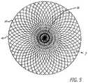
- FIG. 5is a transverse cross sectional view of the device of FIG. 4 taken along lines 5 - 5 in FIG. 4 .
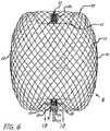
- FIG. 6shows the device of FIG. 4 in longitudinal section taken along lines 6 - 6 in FIG. 4 .
- FIG. 7is an enlarged view of the woven filament structure taken from the encircled portion 7 shown in FIG. 5 .
- FIG. 8is an enlarged view of the woven filament structure taken from the encircled portion 8 shown in FIG. 6 .
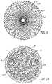
- FIG. 9is a proximal end view of the device of FIG. 3 .
- FIG. 10is a transverse sectional view of a proximal hub portion of the device in FIG. 6 indicated by lines 10 - 10 in FIG. 6 .
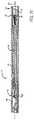
- FIG. 11is an elevation view in partial section of a distal end of a delivery catheter with the device for treatment of a patient's vasculature of FIG. 3 disposed therein in a collapsed constrained state.
- FIG. 12illustrates an embodiment of a filament configuration for a device for treatment of a patient's vasculature.
- FIG. 13illustrates a device for treatment of a patient's vasculature.
- FIG. 14illustrates a device for treatment of a patient's vasculature that includes multiple permeable shells.
- FIG. 15illustrates the device for treatment of a patient's vasculature from FIG. 14 with the second permeable shell in a first expanded state.
- FIGS. 16A-16Eillustrates the device of FIG. 15 being delivered into a sidewall aneurysm.
- FIG. 17is a schematic view of a patient being accessed by an introducer sheath, a microcatheter and a device for treatment of a patient's vasculature releasably secured to a distal end of a delivery device or actuator.
- FIG. 18is a sectional view of a terminal aneurysm.
- FIG. 19is a sectional view of an aneurysm.
- FIG. 20is a schematic view in section of an aneurysm showing perpendicular arrows which indicate interior nominal longitudinal and transverse dimensions of the aneurysm.
- FIG. 21is a schematic view in section of the aneurysm of FIG. 20 with a dashed outline of a device for treatment of a patient's vasculature in a relaxed unconstrained state that extends transversely outside of the walls of the aneurysm.
- FIG. 22is a schematic view in section of an outline of a device represented by the dashed line in FIG. 21 in a deployed and partially constrained state within the aneurysm.
- FIGS. 23-26show a deployment sequence of a device for treatment of a patient's vasculature.
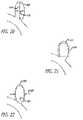
- FIG. 27is an elevation view in partial section of an embodiment of a device for treatment of a patient's vasculature deployed within an aneurysm at a tilted angle.
- FIG. 28is an elevation view in partial section of an embodiment of a device for treatment of a patient's vasculature deployed within an irregularly shaped aneurysm.
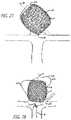
- FIG. 29shows an elevation view in section of a device for treatment of a patient's vasculature deployed within a vascular defect aneurysm.
- some device embodimentsmay be configured for collapse to a low profile constrained state with a transverse dimension suitable for delivery through an inner lumen of a microcatheter and deployment from a distal end thereof.
- Embodiments of these devicesmay also maintain a clinically effective configuration with sufficient mechanical integrity once deployed so as to withstand dynamic forces within a patient's vasculature over time that may otherwise result in compaction of a deployed device. It may also be desirable for some device embodiments to acutely occlude a vascular defect of a patient during the course of a procedure in order to provide more immediate feedback regarding success of the treatment to a treating physician.
- Intrasaccular occlusive devicesthat include a permeable shell formed from a woven or braided mesh have been described in US 2017/0095254, US 2016/0249934, US 2016/0367260, US 2016/0249937, and US 2018/0000489, all of which are hereby expressly incorporated by reference in their entirety for all purposes.
- Some embodimentsare particularly useful for the treatment of cerebral aneurysms by reconstructing a vascular wall so as to wholly or partially isolate a vascular defect from a patient's blood flow.
- Some embodimentsmay be configured to be deployed within a vascular defect to facilitate reconstruction, bridging of a vessel wall or both in order to treat the vascular defect.
- the permeable shell of the devicemay be configured to anchor or fix the permeable shell in a clinically beneficial position.
- the devicemay be disposed in whole or in part within the vascular defect in order to anchor or fix the device with respect to the vascular structure or defect.
- the permeable shellmay be configured to span an opening, neck or other portion of a vascular defect in order to isolate the vascular defect, or a portion thereof, from the patient's nominal vascular system in order allow the defect to heal or to otherwise minimize the risk of the defect to the patient's health.
- the permeable shellmay be configured to allow some initial perfusion of blood through the permeable shell.
- the porosity of the permeable shellmay be configured to sufficiently isolate the vascular defect so as to promote healing and isolation of the defect, but allow sufficient initial flow through the permeable shell so as to reduce or otherwise minimize the mechanical force exerted on the membrane the dynamic flow of blood or other fluids within the vasculature against the device.
- a portion of the permeable shell that spans the opening or neck of the vascular defectneed be permeable and/or conducive to thrombus formation in a patient's bloodstream.
- that portion of the device that does not span an opening or neck of the vascular defectmay be substantially non-permeable or completely permeable with a pore or opening configuration that is too large to effectively promote thrombus formation.
- a hollow, thin walled devicewith a permeable shell of resilient material that may be constrained to a low profile for delivery within a patient.
- a devicemay also be configured to expand radially outward upon removal of the constraint such that the shell of the device assumes a larger volume and fills or otherwise occludes a vascular defect within which it is deployed.
- the outward radial expansion of the shellmay serve to engage some or all of an inner surface of the vascular defect whereby mechanical friction between an outer surface of the permeable shell of the device and the inside surface of the vascular defect effectively anchors the device within the vascular defect.
- Some embodiments of such a devicemay also be partially or wholly mechanically captured within a cavity of a vascular defect, particularly where the defect has a narrow neck portion with a larger interior volume.
- some device embodimentsinclude a matrix of woven or braided filaments that are coupled together by the interwoven structure so as to form a self-expanding permeable shell having a pore or opening pattern between couplings or intersections of the filaments that is substantially regularly spaced and stable, while still allowing for conformity and volumetric constraint.
- woven and braidedare used interchangeably to mean any form of interlacing of filaments to form a mesh structure.
- these termsmay have different or more specific meanings depending on the product or application such as whether an article is made in a sheet or cylindrical form. For purposes of the present disclosure, these terms are used interchangeably.
- three factorsmay be critical for a woven or braided wire occlusion device for treatment of a patient's vasculature that can achieve a desired clinical outcome in the endovascular treatment of cerebral aneurysms.
- the implant devicemay be desirable for the implant device to have sufficient radial stiffness for stability, limited pore size for near-complete acute (intra-procedural) occlusion and a collapsed profile which is small enough to allow insertion through an inner lumen of a microcatheter.
- a device with a radial stiffness below a certain thresholdmay be unstable and may be at higher risk of embolization in some cases.
- some embodiments of devices for treatment of a patient's vasculaturecall for sizing the device which approximates (or with some over-sizing) the vascular site dimensions to fill the vascular site.
- scaling of a device to larger dimensions and using larger filamentswould suffice for such larger embodiments of a device.
- the diameter or profile of the radially collapsed deviceis limited by the catheter sizes that can be effectively navigated within the small, tortuous vessels of the brain.
- the pores or openings between junctions of the filamentsare correspondingly larger.
- flexural modulusmay be defined as the ratio of stress to strain.
- a devicemay be considered to have a high flexural modulus or be stiff if the strain (deflection) is low under a given force.
- a stiff devicemay also be said to have low compliance.
- an outward radial force exerted by an outside surface of the filaments 14 of the device 10 against a constraining force when inserted into a vascular site such as blood vessel or aneurysmis lower for a given amount of device compression or over-sizing. This force may be important in some applications to assure device stability and to reduce the risk of migration of the device and potential distal embolization.
- a combination of small and large filament sizesmay be utilized to make a device with a desired radial compliance and yet have a collapsed profile which is configured to fit through an inner lumen of commonly used microcatheters.
- a device fabricated with even a small number of relatively large filaments 14can provide reduced radial compliance (or increased stiffness) compared to a device made with all small filaments.
- Even a relatively small number of larger filamentsmay provide a substantial increase in bending stiffness due to change in the moment of Inertia that results from an increase in diameter without increasing the total cross sectional area of the filaments.
- the stiffnesscan be increased by a significant amount without a large increase in the cross sectional area of a collapsed profile of the device 10 .
- Thismay be particularly important as device embodiments are made larger to treat large aneurysms. While large cerebral aneurysms may be relatively rare, they present an important therapeutic challenge as some embolic devices currently available to physicians have relatively poor results compared to smaller aneurysms.
- some embodiments of devices for treatment of a patient's vasculaturemay be formed using a combination of filaments 14 with a number of different diameters such as 2, 3, 4, 5 or more different diameters or transverse dimensions.
- some larger filament embodimentsmay have a transverse dimension of about 0.001 inches to about 0.004 inches and some small filament embodiments may have a transverse dimension or diameter of about 0.0004 inches and about 0.0015 inches, more specifically, about 0.0004 inches to about 0.001 inches.
- the ratio of the number of large filaments to the number of small filamentsmay be between about 2 and 12 and may also be between about 4 and 8.
- the difference in diameter or transverse dimension between the larger and smaller filamentsmay be less than about 0.004 inches, more specifically, less than about 0.0035 inches, and even more specifically, less than about 0.002 inches.
- device embodiments 10 for treatment of a patient's vasculaturemay include a plurality of wires, fibers, threads, tubes or other filamentary elements that form a structure that serves as a permeable shell.
- a globular shapemay be formed from such filaments by connecting or securing the ends of a tubular braided structure.
- the density of a braided or woven structuremay inherently increase at or near the ends where the wires or filaments 14 are brought together and decrease at or near a middle portion 30 disposed between a proximal end 32 and distal end 34 of the permeable shell 40 .
- an end or any other suitable portion of a permeable shell 40may be positioned in an opening or neck of a vascular defect such as an aneurysm for treatment.
- a braided or woven filamentary device with a permeable shellmay not require the addition of a separate defect spanning structure having properties different from that of a nominal portion of the permeable shell to achieve hemostasis and occlusion of the vascular defect.
- Such a filamentary devicemay be fabricated by braiding, weaving or other suitable filament fabrication techniques. Such device embodiments may be shape set into a variety of three-dimensional shapes such as discussed herein.
- the device 10includes a self-expanding resilient permeable shell 40 having a proximal end 32 , a distal end 34 , a longitudinal axis 46 and further comprising a plurality of elongate resilient filaments 14 including large filaments 48 and small filaments 50 of at least two different transverse dimensions as shown in more detail in FIGS. 5, 7, and 8 .
- the filaments 14have a woven structure and are secured relative to each other at proximal ends 60 and distal ends 62 thereof.
- the permeable shell 40 of the devicehas a radially constrained elongated state configured for delivery within a microcatheter 61 , as shown in FIG. 11 , with the thin woven filaments 14 extending longitudinally from the proximal end 42 to the distal end 44 radially adjacent each other along a length of the filaments.
- the permeable shell 40also has an expanded relaxed state with a globular and longitudinally shortened configuration relative to the radially constrained state.
- the woven filaments 14form the self-expanding resilient permeable shell 40 in a smooth path radially expanded from a longitudinal axis 46 of the device between the proximal end 32 and distal end 34 .
- the woven structure of the filaments 14includes a plurality of openings 64 in the permeable shell 40 formed between the woven filaments.
- the largest of said openings 64may be configured to allow blood flow through the openings only at a velocity below a thrombotic threshold velocity.
- Thrombotic threshold velocityhas been defined, at least by some, as the time-average velocity at which more than 50% of a vascular graft surface is covered by thrombus when deployed within a patient's vasculature.
- a slightly different thresholdmay be appropriate.
- the thrombotic threshold velocity as used hereinshall include the velocity at which clotting occurs within or on a device, such as device 10 , deployed within a patient's vasculature such that blood flow into a vascular defect treated by the device is substantially blocked in less than about 1 hour or otherwise during the treatment procedure.
- the blockage of blood flow into the vascular defectmay be indicated in some cases by minimal contrast agent entering the vascular defect after a sufficient amount of contrast agent has been injected into the patient's vasculature upstream of the implant site and visualized as it dissipates from that site.
- Such sustained blockage of flow within less than about 1 hour or during the duration of the implantation proceduremay also be referred to as acute occlusion of the vascular defect.
- any blood flowing through the permeable shellmay be slowed to a velocity below the thrombotic threshold velocity and thrombus will begin to form on and around the openings in the permeable shell 40 .
- this processmay be configured to produce acute occlusion of the vascular defect within which the device 10 is deployed.
- at least the distal end of the permeable shell 40may have a reverse bend in an everted configuration such that the secured distal ends 62 of the filaments 14 are withdrawn axially within the nominal permeable shell structure or contour in the expanded state.
- the proximal end of the permeable shellfurther includes a reverse bend in an everted configuration such that the secured proximal ends 60 of the filaments 14 are withdrawn axially within the nominal permeable shell structure 40 in the expanded state.
- evertedmay include a structure that is everted, partially everted and/or recessed with a reverse bend as shown in the device embodiment of FIGS. 3-6 .
- the ends 60 and 62 of the filaments 14 of the permeable shell or hub structure disposed around the endsmay be withdrawn within or below the globular shaped periphery of the permeable shell of the device.
- the elongate resilient filaments 14 of the permeable shell 40may be secured relative to each other at proximal ends 60 and distal ends 62 thereof by one or more methods including welding, soldering, adhesive bonding, epoxy bonding or the like.
- a distal hub 66may also be secured to the distal ends 62 of the thin filaments 14 of the permeable shell 40 and a proximal hub 68 secured to the proximal ends 60 of the thin filaments 14 of the permeable shell 40 .
- the proximal hub 68may include a cylindrical member that extends proximally beyond the proximal ends 60 of the thin filaments so as to form a cavity 70 within a proximal portion of the proximal hub 68 .
- the proximal cavity 70may be used for holding adhesives such as epoxy, solder or any other suitable bonding agent for securing an elongate detachment tether 72 that may in turn be detachably secured to a delivery apparatus such as is shown in FIG. 11 .
- the elongate resilient filaments 14 of the permeable shell 40may have a transverse cross section that is substantially round in shape and be made from a superelastic material that may also be a shape memory metal.
- the shape memory metal of the filaments of the permeable shell 40may be heat set in the globular configuration of the relaxed expanded state as shown in FIGS. 3-6 .
- Suitable superelastic shape memory metalsmay include alloys such as NiTi alloy and the like.
- the superelastic properties of such alloysmay be useful in providing the resilient properties to the elongate filaments 14 so that they can be heat set in the globular form shown, fully constrained for delivery within an inner lumen of a microcatheter and then released to self expand back to substantially the original heat set shape of the globular configuration upon deployment within a patient's body.
- the device 10may have an everted filamentary structure with a permeable shell 40 having a proximal end 32 and a distal end 34 in an expanded relaxed state.
- the permeable shell 40has a substantially enclosed configuration for the embodiments shown. Some or all of the permeable shell 40 of the device 10 may be configured to substantially block or impede fluid flow or pressure into a vascular defect or otherwise isolate the vascular defect over some period of time after the device is deployed in an expanded state.
- the permeable shell 40 and device 10generally also has a low profile, radially constrained state, as shown in FIG. 11 , with an elongated tubular or cylindrical configuration that includes the proximal end 32 , the distal end 34 and a longitudinal axis 46 .
- the elongate flexible filaments 14 of the permeable shell 40may be disposed substantially parallel and in close lateral proximity to each other between the proximal end and distal end forming a substantially tubular or compressed cylindrical configuration.
- Proximal ends 60 of at least some of the filaments 14 of the permeable shell 40may be secured to the proximal hub 68 and distal ends 62 of at least some of the filaments 14 of the permeable shell 40 are secured to the distal hub 66 , with the proximal hub 68 and distal hub 66 being disposed substantially concentric to the longitudinal axis 46 as shown in FIG. 4 .
- the ends of the filaments 14may be secured to the respective hubs 66 and 68 by any of the methods discussed above with respect to securement of the filament ends to each other, including the use of adhesives, solder, welding and the like.
- a middle portion 30 of the permeable shell 40may have a first transverse dimension with a low profile suitable for delivery from a microcatheter as shown in FIG. 11 .
- Radial constraint on the device 10may be applied by an inside surface of the inner lumen of a microcatheter, such as the distal end portion of the microcatheter 61 shown, or it may be applied by any other suitable mechanism that may be released in a controllable manner upon ejection of the device 10 from the distal end of the catheter.
- a proximal end or hub 68 of the device 10is secured to a distal end of an elongate delivery apparatus 111 of a delivery system 112 disposed at the proximal hub 68 of the device 10 . Additional details of delivery devices can be found in, e.g., US 2016/0367260, which was previously incorporated by reference in its entirety.
- Some device embodiments 10 having a braided or woven filamentary structuremay be formed using about 10 filaments to about 300 filaments 14 , more specifically, about 10 filaments to about 100 filaments 14 , and even more specifically, about 60 filaments to about 80 filaments 14 .
- Some embodiments of a permeable shell 40may include about 70 filaments to about 300 filaments extending from the proximal end 32 to the distal end 34 , more specifically, about 100 filaments to about 200 filaments extending from the proximal end 32 to the distal end 34 .
- the filaments 14may have a transverse dimension or diameter of about 0.0008 inches to about 0.004 inches.
- the elongate resilient filaments 14in some cases may have an outer transverse dimension or diameter of about 0.0005 inch to about 0.005 inch, more specifically, about 0.001 inch to about 0.003 inch, and in some cases about 0.0004 inches to about 0.002 inches.
- the large filaments 48 of the permeable shell 40may have a transverse dimension or diameter that is about 0.001 inches to about 0.004 inches and the small filaments 50 may have a transverse dimension or diameter of about 0.0004 inches to about 0.0015 inches, more specifically, about 0.0004 inches to about 0.001 inches.
- a difference in transverse dimension or diameter between the small filaments 50 and the large filaments 48may be less than about 0.004 inches, more specifically, less than about 0.0035 inches, and even more specifically, less than about 0.002 inches.
- the number of small filaments 50 of the permeable shell 40 relative to the number of large filaments 48 of the permeable shell 40may be about 2 to 1 to about 15 to 1, more specifically, about 2 to 1 to about 12 to 1, and even more specifically, about 4 to 1 to about 8 to 1.
- the expanded relaxed state of the permeable shell 40has an axially shortened configuration relative to the constrained state such that the proximal hub 68 is disposed closer to the distal hub 66 than in the constrained state.
- Both hubs 66 and 68are disposed substantially concentric to the longitudinal axis 46 of the device and each filamentary element 14 forms a smooth arc between the proximal and distal hubs 66 and 68 with a reverse bend at each end.
- a longitudinal spacing between the proximal and distal hubs 66 and 68 of the permeable shell 40 in a deployed relaxed statemay be about 25 percent to about 75 percent of the longitudinal spacing between the proximal and distal hubs 66 and 68 in the constrained cylindrical state, for some embodiments.
- the arc of the filaments 14 between the proximal and distal ends 32 and 34may be configured such that a middle portion of each filament 14 has a second transverse dimension substantially greater than the first transverse dimension.
- the permeable shell 40may have a first transverse dimension in a collapsed radially constrained state of about 0.2 mm to about 2 mm and a second transverse dimension in a relaxed expanded state of about 4 mm to about 30 mm.
- the second transverse dimension of the permeable shell 40 in an expanded statemay be about 2 times to about 150 times the first transverse dimension, more specifically, about 10 times to about 25 times the first or constrained transverse dimension.
- a longitudinal spacing between the proximal end 32 and distal end 34 of the permeable shell 40 in the relaxed expanded statemay be about 25% percent to about 75% percent of the spacing between the proximal end 32 and distal end 34 in the constrained cylindrical state.
- a major transverse dimension of the permeable shell 40 in a relaxed expanded statemay be about 4 mm to about 30 mm, more specifically, about 9 mm to about 15 mm, and even more specifically, about 4 mm to about 8 mm.
- An arced portion of the filaments 14 of the permeable shell 40may have a sinusoidal-like shape with a first or outer radius 88 and a second or inner radius 90 near the ends of the permeable shell 40 as shown in FIG. 6 .
- This sinusoid-like or multiple curve shapemay provide a concavity in the proximal end 32 that may reduce an obstruction of flow in a parent vessel adjacent a vascular defect.
- the first radius 88 and second radius 90 of the permeable shell 40may be between about 0.12 mm to about 3 mm.
- the distance between the proximal end 32 and distal end 34may be less than about 60% of the overall length of the permeable shell 40 for some embodiments.
- each filament 14may have a substantially continuous curvature. This substantially continuous curvature may provide smooth deployment and may reduce the risk of vessel perforation.
- one of the ends 32 or 34may be retracted or everted to a greater extent than the other so as to be more longitudinally or axially conformal than the other end.
- the first radius 88 and second radius 90 of the permeable shell 40may be between about 0.12 mm to about 3 mm for some embodiments.
- the distance between the proximal end 32 and distal end 34may be more than about 60% of the overall length of the expanded permeable shell 40 .
- the largest longitudinal distance between the inner surfacesmay be about 60% to about 90% of the longitudinal length of the outer surfaces or the overall length of device 10 .
- a gap between the hubs 66 and 68 at the proximal end 32 and distal end 34may allow for the distal hub 66 to flex downward toward the proximal hub 68 when the device 10 meets resistance at the distal end and thus provides longitudinal conformance.
- the filaments 14may be shaped such that there are no portions that are without curvature over a distance of more than about 2 mm. Thus, for some embodiments, each filament 14 may have a substantially continuous curvature. This substantially continuous curvature may provide smooth deployment and may reduce the risk of vessel perforation.
- the distal end 34may be retracted or everted to a greater extent than the proximal end 32 such that the distal end portion of the permeable shell 40 may be more radially conformal than the proximal end portion. Conformability of a distal end portion may provide better device conformance to irregular shaped aneurysms or other vascular defects.
- a convex surface of the devicemay flex inward forming a concave surface to conform to curvature of a vascular site.
- FIG. 10shows an enlarged view of the filaments 14 disposed within a proximal hub 68 of the device 10 with the filaments 14 of two different sizes constrained and tightly packed by an outer ring of the proximal hub 68 .
- the tether member 72may optionally be disposed within a middle portion of the filaments 14 or within the cavity 70 of the proximal hub 68 proximal of the proximal ends 60 of the filaments 14 as shown in FIG. 6 .
- the distal end of the tether 72may be secured with a knot 92 formed in the distal end thereof which is mechanically captured in the cavity 70 of the proximal hub 68 formed by a proximal shoulder portion 94 of the proximal hub 68 .
- the knotted distal end 92 of the tether 72may also be secured by bonding or potting of the distal end of the tether 72 within the cavity 70 and optionally amongst the proximal ends 60 of the filaments 14 with mechanical compression, adhesive bonding, welding, soldering, brazing or the like.
- the tether embodiment 72 shown in FIG. 6has a knotted distal end 92 potted in the cavity of the proximal hub 68 with an adhesive.
- Such a tether 72may be a dissolvable, severable or releasable tether that may be part of a delivery apparatus 111 used to deploy the device 10 as shown in FIG. 11 and FIGS. 23-26 .
- FIG. 10also shows the large filaments 48 and small filaments 50 disposed within and constrained by the proximal hub 68 which may be configured to secure the large and small filaments 48 and 50 in place relative to each other within the outer ring of the proximal hub 68 .
- FIGS. 7 and 8illustrate some configuration embodiments of braided filaments 14 of a permeable shell 40 of the device 10 for treatment of a patient's vasculature.
- the braid structure in each embodimentis shown with a circular shape 100 disposed within a pore 64 of a woven or braided structure with the circular shape 100 making contact with each adjacent filament segment.
- the pore opening sizemay be determined at least in part by the size of the filament elements 14 of the braid, the angle overlapping filaments make relative to each other and the picks per inch of the braid structure.
- the cells or openings 64may have an elongated substantially diamond shape as shown in FIG.
- the pores or openings 64 of the permeable shell 40may have a substantially more square shape toward a middle portion 30 of the device 10 , as shown in FIG. 8 .
- the diamond shaped pores or openings 64may have a length substantially greater than the width particularly near the hubs 66 and 68 .
- the ratio of diamond shaped pore or opening length to widthmay exceed a ratio of 3 to 1 for some cells.
- the diamond-shaped openings 64may have lengths greater than the width thus having an aspect ratio, defined as Length/Width of greater than 1.
- the openings 64 near the hubs 66 and 68may have substantially larger aspect ratios than those farther from the hubs as shown in FIG. 7 .
- the aspect ratio of openings 64 adjacent the hubsmay be greater than about 4 to 1.
- the aspect ratio of openings 64 near the largest diametermay be between about 0.75 to 1 and about 2 to 1 for some embodiments.
- the aspect ratio of the openings 64 in the permeable shell 40may be about 0.5 to 1 to about 2 to 1.
- the pore size defined by the largest circular shapes 100 that may be disposed within openings 64 of the braided structure of the permeable shell 40 without displacing or distorting the filaments 14 surrounding the opening 64may range in size from about 0.005 inches to about 0.01 inches, more specifically, about 0.006 inches to about 0.009 inches, even more specifically, about 0.007 inches to about 0.008 inches for some embodiments.
- at least some of the openings 64 formed between adjacent filaments 14 of the permeable shell 40 of the device 10may be configured to allow blood flow through the openings 64 only at a velocity below a thrombotic threshold velocity.
- the largest openings 64 in the permeable shell structure 40may be configured to allow blood flow through the openings 64 only at a velocity below a thrombotic threshold velocity.
- the pore sizemay be less than about 0.016 inches, more specifically, less than about 0.012 inches for some embodiments.
- the openings 64 formed between adjacent filaments 14may be about 0.005 inches to about 0.04 inches.
- FIG. 12illustrates in transverse cross section an embodiment of a proximal hub 68 showing the configuration of filaments which may be tightly packed and radially constrained by an inside surface of the proximal hub 68 .
- the braided or woven structure of the permeable shell 40 formed from such filaments 14may be constructed using a large number of small filaments.
- the number of filaments 14may be greater than 125 and may also be between about 80 filaments and about 180 filaments.
- the total number of filaments 14for some embodiments may be about 70 filaments to about 300 filaments, more specifically, about 100 filaments to about 200 filaments.
- the braided structure of the permeable shell 40may be constructed with two or more sizes of filaments 14 .
- the structuremay have several larger filaments that provide structural support and several smaller filaments that provide the desired pore size and density and thus flow resistance to achieve a thrombotic threshold velocity in some cases.
- small filaments 50 of the permeable shell 40may have a transverse dimension or diameter of about 0.0006 inches to about 0.002 inches for some embodiments and about 0.0004 inches to about 0.001 inches in other embodiments.
- the large filaments 48may have a transverse dimension or diameter of about 0.0015 inches to about 0.004 inches in some embodiments and about 0.001 inches to about 0.004 inches in other embodiments.
- the filaments 14may be braided in a plain weave that is one under, one over structure (shown in FIGS. 7 and 8 ) or a supplementary weave; more than one warp interlace with one or more than one weft.
- the pick countmay be varied between about 25 and 200 picks per inch (PPI).
- Intrasaccular occlusive devicescan sometimes utilize an apple-core braid winding shape, where a proximal 137 a and/or distal stem 137 b are include at or near the proximal 132 and distal 134 ends of device 110 .
- the proximal stem 137 arepresents the attachment junction with a mechanical pusher device used to place the device 110 .
- a hub(sometimes configured as a tubular marker band) is used within this region as an attachment junction for all the associated wires comprising the device—meaning the various wires comprising the intrasaccular device may proximally terminate at the hub interface, as shown and described with respect to earlier embodiments (e.g., FIG. 6 ).
- a tubular marker bande.g. made of a radiopaque material such as tantalum, gold, platinum, or palladium
- the wirescan terminate/mate to an external surface of the hub, or along an internal lumen of the hub.
- the tubular marker bandmay sit over a terminal portion of the stem 137 a or 137 b .
- the hub/tubular markerdoes not extend proximally or distally beyond the length of the device itself. In other embodiments, the hub/tubular marker does extend proximally and/or distally beyond the length of the device such that it juts out proximally and/or distally beyond the rest of the mesh occlusive device—meaning the hub/tubular marker may extend proximally past a plane defined by the proximal most edge of the expanded state of the permeable shell 140 , and distally beyond a plane defined by the distal most edge of the expanded state of the permeable shell 140 .
- the proximal stem 137 acan sit within a proximal dimpled, recessed, or concave section 133 . Often this proximal dimpled, recessed, or concave section 133 helps ensure the device 110 can sit within the target region while also occluding the target region. In some circumstances, the proximal stem 137 a may jut out of the treatment site (e.g., aneurysm) and into the parent vessel when implanted due to various reasons. Some reasons may include the dimensions of the associated treatment site in which the device is occluding (e.g., the sizing of the device relative to the aneurysm), and/or the proximal neck opening of the aneurysm.
- the treatment sitee.g., aneurysm
- Some reasonsmay include the dimensions of the associated treatment site in which the device is occluding (e.g., the sizing of the device relative to the aneurysm), and/
- intrasaccular occlusion devices or intrasaccular flow disruption devicesit is desirable to have a significant flow-disruption effect at the proximal end of the device to reduce the blood flow at the neck region—in turn, thereby reducing blood flow in the aneurysm.
- the mesh of braided wires forming the proximal dimpled region 133 of the devicehelps provide this flow-disruption effect.
- Intra-aneurysmal flow stagnation resulting from the flow disruption effectpromotes thrombosis within the aneurysm and subsequent obliteration of the aneurysm over time.
- Embodiments of this deviceaugment flow-disruption at the proximal end of the device by providing an additional layer or permeable shell that can fill the proximal dimple, recessed, or concave section 133 located at a proximal region of the intrasaccular device. In some cases, these embodiments can facilitate easier placement of an intrasaccular device within a sidewall aneurysm.
- the device 210includes an intrasaccular device portion 240 having a proximal recess 133 and a distal recess 135 , similar to the embodiments described above. Furthermore, distal stem 137 b and proximal stem 237 a are utilized in each proximal recess 133 and distal recess 135 region. Distal stem 137 b is configured similar to the other embodiments, where a tubular hub or marker band (not shown) can be used along the distal end of the stem (e.g., as a distal terminus for the braided implant wires). A proximal stem 237 a is also used.
- the proximal stem 237 ais shorter than the proximal stem 137 a of FIG. 13 and sits completely within the proximal dimpled or concave section 133 .
- the proximal stem 237 ais connected to a second occlusive element 222 .
- device 210includes two interconnected braided structures 240 and 222 , which combine to form a barrel-like or globular-like structure.
- the overall occlusive device 210will comprise the first (distally-oriented) occlusive element 240 and the second (proximally-oriented) occlusive element 222 .
- FIG. 15shows a deployment configuration, whereby occlusive element 222 is in an elongated configuration.
- a proximal end of the occlusive element 222is connected to a delivery pusher 243 (e.g., through a tubular hub or marker band 252 a ), whereby the delivery pusher 243 is used to navigate device 210 (which includes intrasaccular portion 240 and second occlusive portion 222 ).
- the occlusive element 222adopts the elongated configuration shown in FIG. 15 .
- the occlusive element 222adopts a radially expansile and longitudinally compressed configuration—whereby occlusive element 222 sits flush within the proximal dimple, recessed, or concave section 133 of the device 210 in a fully deployed configuration, thereby sealing the neck of the aneurysm/treatment site.
- the inclusion of the occlusive element 222which can span the proximal recessed section 133 of device 210 , augments the flow disruption effect at the proximal end (which spans the neck region of the aneurysm) of the device 210 , due to the additional barrier to blood entry provided by this portion 222 .
- blood flowing into the neck region of the aneurysmwould have to first pass by the wires of the occlusive portion 222 , then the wires of the intrasaccular device portion 240 . In this way, there is increased resistance to blood flow along the proximal, or neck-facing region of the device 210 —thereby augmenting flow disruption at the proximal end of the device.
- both occlusive elements 240 , 222are created from wires made from a shape-memory alloy, such as nitinol wires and/or DFT (drawn filled tubes) and heat set into the shapes shown in FIG. 14 .
- the DFTis composed of a radiopaque (e.g., tantalum, platinum, gold, or palladium) core surrounded by a nitinol jacket.
- a radiopaquee.g., tantalum, platinum, gold, or palladium
- only nitinol wiresare used for occlusive elements 240 , 222 .
- only DFT wiresare used for occlusive elements 240 , 222 .
- a mixture of nitinol and DFT wiresare used along one or both of occlusive elements 240 , 222 (e.g., where one is solely composed of nitinol and the other solely composed of DFT, or where one or both are composed of a mixture of DFT and nitinol wires).
- the first occlusive element 240is manufactured and heat set into the barrel-like structure having proximal 133 and distal 135 dimpled concave sections.
- the second occlusive element 222is then manufactured and heat set such that the distally-facing (or upward facing, in the context of FIGS. 14-15 ) outer surface of the second occlusive element 222 is configured to conform or mate with the proximally-facing (or downward facing, in the context of the same figures) surface of the proximal dimpled region 133 .
- the second occlusive element 222is configured to adopt a convex shape that mates with the concave shape of the proximal dimpled section 133 when implanted.
- the two occlusive elements 240 , 222may be connected, for instance by a hub or marker band element.
- the first and second occlusive elements 240 , 222are made from the same tubular mesh (same woven filaments), where the second occlusive element is formed of wires which are tracked through the narrow diameter proximal stem region and then wound into the dimpled region of the first occlusive element.
- the devicecan be manufactured by wrapping a single tubular mesh around a fixture containing the shape of occlusive elements 240 , 222 . The fixture and the braided mesh can then be heat set to obtain the secondary shape memory.
- first and second occlusive elementscan either be completely separate mesh braids or can be formed from the same mesh braid wound in a particular configuration.
- Proximal hub or marker band 252 a(and a distal hub or marker band, not shown) can then be attached to the device, respectively, at the proximal and distal ends.
- the proximal hub or marker band 252 acan then be attached to a pusher 243 .
- a hub or marker bandcan be placed between occlusive element 222 and occlusive element 240 .
- the wiresare passed through a hub or marker band and then continue into the second occlusive element.
- no hub or marker bandis used and, instead, the wires simply extend from a distal end or region of occlusive portion 240 , through stem 237 a , to the proximal end or region of occlusive portion 222 .
- a device in which there is no hub or marker band between the first and second occlusive elements 240 , 222may be less stiff than an embodiment including a hub or marker band.
- a hub or marker bandcan be used between these two sections (e.g., along proximal stem 237 a ) where the wires of occlusive element 240 terminate along an external or internal surface of the hub or marker band, and the separate wires of occlusive element 222 then begin along an external or internal surface of the same hub or marker band.
- the wires of occlusive element 240proximally terminate at a first hub or marker band and the separate wires of occlusive element 222 begin at an adjacent hub or hub or marker band.
- the second occlusive element 222which bridges the space in the proximal dimpled or concave section 133 of the first occlusive element 240 , has good shape retention properties that enable it to fit into the dimpled recessed shape of proximal dimpled region 133 .
- the second occlusive element 222also provides additional push strength as a bridge between the proximal mechanical pusher 243 and the distal first occlusive element, thereby providing more control during deployment.
- FIG. 15illustrates a configuration of the device when it is being delivered.
- the first occlusive element 240adopts its heat seat, expanded configuration when freed from a delivery catheter (not shown).
- the proximal end of the first occlusive element 240is connected to a distal end of the second occlusive element 222 through proximal stem or elongate proximal extension 237 a , which acts as a flexible joint allowing the first occlusive element 240 to pivot or flex relative to the second occlusive element 222 .
- the userUpon delivery, the user distally advances the pusher 243 so that the proximal occlusive element 222 is pushed into recess 133 to occupy the space of the recess—such that the configuration in FIG. 14 is adopted.
- the pusheris then detached from the device 210 so that the device 210 remains as an implant.
- the device 210contains a braided region that acts as a flexible joint 237 a between the first 240 and second 222 occlusive elements.
- the device 210is delivered using a microcatheter 61 and pusher 243 , which is connected to a proximal end of the device 210 .
- an aneurysme.g., a sidewall aneurysm
- the flexible joint between the first 240 and second 222 occlusive elementsallows for easier delivery because the first occlusive element 240 is capable of deflecting or pivoting relative to a longitudinal axis formed by the pusher and the second permeable shell or a longitudinal axis of the second permeable shell.
- the flexible joint 237 a between the first and second occlusive elementsallows for the first occlusive element 240 to deflect, bend, or flex at an angle of up to about 180°, alternatively up to about 150°, alternatively up to about 120°, alternatively up to about 90°, alternatively up to about 60°, alternatively up to about 45°, alternatively up to about 30°, alternatively up to about 10°.
- the second occlusive element 222will generally adopt a more elongated shape during delivery, e.g., while in the microcatheter.
- the second occlusive element 222After release from the lumen of the microcatheter but before placement within the proximal concave section of the first occlusive element 240 , the second occlusive element 222 will adopt a first expanded state while the second occlusive element is under tension from a proximal direction.
- the first expanded statehas a longer length and smaller radius than the second expanded state that the second occlusive element adopts after the proximal tension is released or a force is applied to push it against the proximal end of the first permeable shell.
- the second occlusive element 222Upon placement within the aneurysm and release of the proximal tension, the second occlusive element 222 will abut the first occlusive element 240 within the proximal dimpled concave region 133 and assume the second expanded state, which is configured to sit within the proximal dimpled concave region 133 .
- the deployment of device 210 with the second occlusive element 222 seated in the proximal dimpled concave region 133assists in occluding blood flow at the proximal end of the device 210 and forming a strong proximal occlusive barrier to blood flow.
- the second occlusive element 222will be heat set into a convex shape that generally fills the proximal concave section. Thus, it will readily adopt this convex shape that mates with the dimpled concave shape of the proximal region of the first occlusive device 210 . The user will then detach the pusher 243 from the proximal end of the second occlusive element 222 , thereby leaving the occlusive implant 210 within the target treatment region (e.g., an aneurysm 160 ).
- the target treatment regione.g., an aneurysm 160
- the second occlusive device 222along with providing increased resistance to blood flow at the neck of the aneurysm by filling in the recess 133 , can also help pivot the connected occlusive portion 240 into a proper orientation after deployment into the treatment site.
- intrasaccular devicescan be optimal treatments for bifurcation aneurysms where a catheter can be delivered directly from a parent artery into the aneurysm at a vessel bifurcation junction. This is more complicated for sidewall aneurysms, where the catheter often comes into the aneurysm at an odd, non-linear angle.
- the intrasaccular devicemay be deployed at an odd angle, and closer to one side of the aneurysm rather than directly in the middle.
- This odd delivery anglecan negatively affect flow disruption at the neck of the aneurysm, which can contribute to the intrasaccular device shifting within the aneurysm over time.
- Sidewall aneurysmsalso can be irregularly shaped, further making proper entry and seating of the intrasaccular device in the aneurysm difficult. Because the second occlusive device 222 is proximally oriented with respect to the primary occlusive portion 240 , during implantation, the second occlusive portion 222 will exert force against the distally connected occlusive portion 240 .
- This force or exertioncan help orient the primary occlusive portion 240 into a proper orientation and position in the aneurysm after it is deployed from the delivery catheter.
- the sidewall aneurysmcan be angled, for instance at about 90 degrees or between about 60-120 degrees relative to the parent artery.
- the secondary occlusive section 222can help in articulating or positioning the overall intrasaccular device to be located in a proper orientation within the aneurysm. This is due to the force provided by the proximal occlusive portion 222 , as well as the flexible nature of joint/stem 237 a , as described earlier.
- the proximal occlusive section 222offers some advantages in deployment in sidewall aneurysms, this additional section 222 also offers some advantages when used in bifurcation aneurysms as well.
- the proximal occlusive section 222offers additional blood disruption at the proximal section of the device 210 toward the neck-portion of the aneurysm, thereby reducing blood flow into the aneurysm and promoting healing over time.
- the articulation described abovecan be used to properly position the intrasaccular device 210 within a bifurcation aneurysm, for example in a particularly wide or large-necked aneurysm where it may be difficult to otherwise seat the intrasaccular device 210 properly with regard to the neck region of the aneurysm.
- the first occlusive element 240 and second occlusive element 222comprise similar metallic wire material.
- the first occlusive element 240may be softer and have a more flexible configuration than the second occlusive element 222 . More stiffness may be desirable along the proximal occlusive element 222 in order to provide enough push force against first occlusive element 240 and to provide more flow resistance along the proximal section of the intrasaccular implant 210 .
- the first occlusive element 240for instance, can use relatively smaller wires and/or a denser wind pattern than the second shell 222 in order to achieve this more flexible configuration.
- the second occlusive element 222may be stiffer than the first shell 240 . This enhanced stiffness is achieved, for instance, by use of larger sized wires which are more spread out (e.g. having a smaller pic count).
- the second occlusive element 222can also include radiopaque components, such as tantalum, to further enhance stiffness and well as to augment visualization.
- a good shape memory material, such as nitinol and/or DFT wire,may also be used to create the metallic mesh for the first 240 and second 222 occlusive elements.
- the first occlusive element 240may be formed by weaving or braiding between about 24 and 216 filaments, alternatively between about 60 and 144 filaments, alternatively between about 72 and 108 filaments.
- the filaments that are woven to form the first occlusive element 240may have a diameter of between about 0.0005′′ and 0.002′′, alternatively between about 0.0006′′ and 0.00125′′, alternatively between about 0.00075′′ and 0.001′′.
- the first occlusive element 240may have a radial stiffness between about 0.014 lbf and 0.284 lbf.
- the second occlusive element 222may be formed by weaving or braiding between about 24 and 216 filaments, alternatively between 60 and 144 filaments, alternatively between about 72 and 108 filaments.
- the filaments that are woven to form the second occlusive element 222may have a diameter of between about 0.0005′′ and 0.002′′, alternatively between about 0.0006′′ and 0.00125′′, alternatively between about 0.00075′′ and 0.001′′.
- the second occlusive element 222may have a radial stiffness between about 0.014 lbf and 0.284 lbf.
- the permeable shell 40 , 140 , 240 or portions thereofmay be porous and may be highly permeable to liquids.
- the permeable shell 40 of some embodiments discussed hereinmay have a water permeability greater than about 2,000 ml/min/cm 2 , in some cases greater than about 2,500 ml/min/cm 2 .
- water permeability of the permeable shell 40 or portions thereofmay be between about 2,000 and 10,000 ml/min/cm 2 , more specifically, about 2,000 ml/min/cm 2 to about 15,000 ml/min/cm 2 , when measured at a pressure of 120 mmHg.
- Device embodiments and components thereofmay include metals, polymers, biologic materials and composites thereof.
- Suitable metalsinclude zirconium-based alloys, cobalt-chrome alloys, nickel-titanium alloys, platinum, tantalum, stainless steel, titanium, gold, and tungsten.
- Potentially suitable polymersinclude but are not limited to acrylics, silk, silicones, polyvinyl alcohol, polypropylene, polyvinyl alcohol, polyesters (e.g. polyethylene terephthalate or PET), PolyEtherEther Ketone (PEEK), polytetrafluoroethylene (PTFE), polycarbonate urethane (PCU) and polyurethane (PU).
- Device embodimentsmay include a material that degrades or is absorbed or eroded by the body.
- a bioresorbablee.g., breaks down and is absorbed by a cell, tissue, or other mechanism within the body
- bioabsorbablesimilar to bioresorbable
- a bioerodablee.g., erodes or degrades over time by contact with surrounding tissue fluids, through cellular activity or other physiological degradation mechanisms
- biodegradablee.g., degrades over time by enzymatic or hydrolytic action, or other mechanism in the body
- dissolvable materialmay be employed. Each of these terms is interpreted to be interchangeable.
- bioabsorbable polymere.g., breaks down and is absorbed by a cell, tissue, or other mechanism within the body
- a bioabsorbablee.g., erodes or degrades over time by contact with surrounding tissue fluids, through cellular activity or other physiological degradation mechanisms
- biodegradablee.g., degrades
- bioabsorbable materialsinclude polylactic acid (PLA), poly(alpha-hydroxy acid) such as poly-L-lactide (PLLA), poly-D-lactide (PDLA), polyglycolide (PGA), polydioxanone, polycaprolactone, polygluconate, polylactic acid-polyethylene oxide copolymers, modified cellulose, collagen, poly(hydroxybutyrate), polyanhydride, polyphosphoester, poly(amino acids), or related copolymer materials.
- PLApolylactic acid
- PLLApoly(alpha-hydroxy acid)
- PLLApoly-L-lactide
- PDLApoly-D-lactide
- PGApolyglycolide
- polydioxanonepolycaprolactone
- polygluconatepolylactic acid-polyethylene oxide copolymers
- modified cellulosecollagen, poly(hydroxybutyrate), polyanhydride, polyphosphoester, poly(amino acids), or related copolymer materials.
- An absorbable composite fibermay be made by combining a reinforcement fiber made from a copolymer of about 18% glycolic acid and about 82% lactic acid with a matrix material consisting of a blend of the above copolymer with about 20% polycaprolactone (PCL).
- PCLpolycaprolactone
- Permeable shell embodiments 40 , 140 , 240may be formed at least in part of wire, ribbon, or other filamentary elements. These filamentary elements 14 may have circular, elliptical, ovoid, square, rectangular, or triangular cross-sections. Permeable shell embodiments 40 may also be formed using conventional machining, laser cutting, electrical discharge machining (EDM) or photochemical machining (PCM). If made of a metal, it may be formed from either metallic tubes or sheet material.
- EDMelectrical discharge machining
- PCMphotochemical machining
- Device embodiments 10 , 110 , 210 discussed hereinmay be delivered and deployed from a delivery and positioning system 112 that includes a microcatheter 61 , such as the type of microcatheter 61 that is known in the art of neurovascular navigation and therapy.
- Device embodiments for treatment of a patient's vasculature 10 , 110 , 210may be elastically collapsed and restrained by a tube or other radial restraint, such as an inner lumen 120 of a microcatheter 61 , for delivery and deployment.
- the microcatheter 61may generally be inserted through a small incision 152 accessing a peripheral blood vessel such as the femoral artery or brachial artery.
- the microcatheter 61may be delivered or otherwise navigated to a desired treatment site 154 from a position outside the patient's body 156 over a guidewire 159 under fluoroscopy or by other suitable guiding methods.
- the guidewire 159may be removed during such a procedure to allow insertion of the device 10 , 110 , 210 secured to a delivery apparatus 111 of the delivery system 112 through the inner lumen 120 of a microcatheter 61 in some cases.
- FIG. 17illustrates a schematic view of a patient 158 undergoing treatment of a vascular defect 160 as shown in FIG. 18 .
- An access sheath 162is shown disposed within either a radial artery 164 or femoral artery 166 of the patient 158 with a delivery system 112 that includes a microcatheter 61 and delivery apparatus 111 disposed within the access sheath 162 .
- the delivery system 112is shown extending distally into the vasculature of the patient's brain adjacent a vascular defect 160 in the patient's brain.
- Access to a variety of blood vessels of a patientmay be established, including arteries such as the femoral artery 166 , radial artery 164 , and the like in order to achieve percutaneous access to a vascular defect 160 .
- the patient 158may be prepared for surgery and the access artery is exposed via a small surgical incision 152 and access to the lumen is gained using the Seldinger technique where an introducing needle is used to place a wire over which a dilator or series of dilators dilates a vessel allowing an introducer sheath 162 to be inserted into the vessel. This would allow the device to be used percutaneously.
- a guiding catheter 168is then used to provide a safe passageway from the entry site to a region near the target site 154 to be treated.
- a guiding catheter 168would be chosen which would extend from the entry site 152 at the femoral artery up through the large arteries extending around the heart through the aortic arch, and downstream through one of the arteries extending from the upper side of the aorta such as the carotid artery 170 .
- a guidewire 159 and neurovascular microcatheter 61are then placed through the guiding catheter 168 and advanced through the patient's vasculature, until a distal end 151 of the microcatheter 61 is disposed adjacent or within the target vascular defect 160 , such as an aneurysm.
- exemplary guidewires 159 for neurovascular useinclude the Synchro2® made by Boston Scientific and the Glidewire Gold Neuro® made by MicroVention Terumo. Typical guidewire sizes may include 0.014 inches and 0.018 inches.
- Delivery and deployment of device embodiments 10 , 110 , 210 discussed hereinmay be carried out by first compressing the device 10 , 110 , 210 to a radially constrained and longitudinally flexible state as shown in FIG. 11 .
- the device 10 , 110 , 210may then be delivered to a desired treatment site 154 while disposed within the microcatheter 61 , and then ejected or otherwise deployed from a distal end 151 of the microcatheter 61 .
- the microcatheter 61may first be navigated to a desired treatment site 154 over a guidewire 159 or by other suitable navigation techniques.
- the distal end of the microcatheter 61may be positioned such that a distal port of the microcatheter 61 is directed towards or disposed within a vascular defect 160 to be treated and the guidewire 159 withdrawn.
- the device 10 , 110 , 210 secured to a suitable delivery apparatus 111may then be radially constrained, inserted into a proximal portion of the inner lumen 120 of the microcatheter 61 and distally advanced to the vascular defect 160 through the inner lumen 120 .
- the device 10 , 110 , 210may then allowed to assume an expanded relaxed or partially relaxed state with the permeable shell 40 , 140 , 240 of the device spanning or partially spanning a portion of the vascular defect 160 or the entire vascular defect 160 .
- the device 10 , 110 , 210may also be activated by the application of an energy source to assume an expanded deployed configuration once ejected from the distal section of the microcatheter 61 for some embodiments. Once the device 10 is deployed at a desired treatment site 154 , the microcatheter 61 may then be withdrawn.
- Some embodiments of devices for the treatment of a patient's vasculature 10 , 110 , 210 discussed hereinmay be directed to the treatment of specific types of defects of a patient's vasculature.
- an aneurysm 160 commonly referred to as a terminal aneurysmis shown in section. Terminal aneurysms occur typically at bifurcations in a patient's vasculature where blood flow, indicated by the arrows 172 , from a supply vessel splits into two or more branch vessels directed away from each other.
- Terminal aneurysmsmay have a well-defined neck structure where the profile of the aneurysm 160 narrows adjacent the nominal vessel profile, but other terminal aneurysm embodiments may have a less defined neck structure or no neck structure.
- FIG. 19illustrates a typical berry type aneurysm 160 in section where a portion of a wall of a nominal vessel section weakens and expands into a sack like structure ballooning away from the nominal vessel surface and profile.
- Some berry type aneurysmsmay have a well-defined neck structure as shown in FIG.
- FIG. 19shows some optional procedures wherein a stent 173 or other type of support has been deployed in the parent vessel 174 adjacent the aneurysm. Also, shown is embolic material 176 being deposited into the aneurysm 160 through a microcatheter 61 . Either or both of the stent 173 and embolic material 176 may be so deployed either before or after the deployment of a device for treatment of a patient's vasculature 10 .
- Some embodiments of treatmentmay include estimating a volume of a vascular site or defect 160 to be treated and selecting a device 10 , 110 , 210 with a volume that is substantially the same volume or slightly over-sized relative to the volume of the vascular site or defect 160 .
- the volume of the vascular defect 160 to be occludedmay be determined using three-dimensional angiography or other similar imaging techniques along with software which calculates the volume of a selected region.
- the amount of over-sizingmay be between about 2% and 15% of the measured volume.
- a very irregular shaped aneurysmit may be desirable to under-size the volume of the device 10 , 110 , 210 .
- Small lobes or “daughter aneurysms”may be excluded from the volume, defining a truncated volume which may be only partially filled by the device without affecting the outcome.
- a device 10 , 110 , 210 deployed within such an irregularly shaped aneurysm 160is shown in FIG. 28 discussed below.
- Such a method embodimentmay also include implanting or deploying the device 10 , 110 , 210 so that the vascular defect 160 is substantially filled volumetrically by a combination of device and blood contained therein.
- the device 10 , 110 , 210may be configured to be sufficiently conformal to adapt to irregular shaped vascular defects 160 so that at least about 75%, in some cases about 80%, of the vascular defect volume is occluded by a combination of device 10 , 110 , 210 and blood contained therein.
- FIGS. 20-22illustrate a schematic representation of how a device 10 , 110 , 210 may be chosen for a proper fit after deployment that is initially oversized in a transverse dimension by at least about 10% of the largest transverse dimension of the vascular defect 160 and sometimes up to about 100% of the largest transverse dimension.
- the device 10 , 110 , 210may be oversized a small amount (e.g. less than about 1.5 mm) in relation to measured dimensions for the width, height or neck diameter of the vascular defect 160 .
- a vascular defect 160 in the form of a cerebral aneurysmis shown with horizontal arrows 180 and vertical arrows 182 indicating the approximate largest interior dimensions of the defect 160 .
- Arrow 180 extending horizontallyindicates the largest transverse dimension of the defect 160 .
- a dashed outline 184 of a device for treatment of the vascular defectis shown superimposed over the vascular defect 160 of FIG. 20 illustrating how a device 10 , 110 , 210 that has been chosen to be approximately 20% oversized in a transverse dimension would look in its unconstrained, relaxed state.
- FIG. 22illustrates how the device 10 , 110 , 210 , which is indicated by the dashed line 184 of FIG.
- the device 10 , 110 , 210might conform to the interior surface of the vascular defect 160 after deployment whereby the nominal transverse dimension of the device 10 , 110 , 210 in a relaxed unconstrained state has now been slightly constrained by the inward radial force 185 exerted by the vascular defect 160 on the device 10 , 110 , 210 .
- the device 10 , 110 , 210has assumed a slightly elongated shape in the axial or longitudinal axis of the device 10 so as to elongate and better fill the interior volume of the defect 160 as indicated by the downward arrow 186 in FIG. 22 .
- the delivery and deployment processmay then proceed.
- the properties of the device embodiments 10 , 110 , 210 and delivery system embodiments 112 discussed hereingenerally allow for retraction of a device 10 after initial deployment into a defect 160 , but before detachment of the device 10 , 110 , 210 . Therefore, it may also be possible and desirable to withdraw or retrieve an initially deployed device 10 after the fit within the defect 160 has been evaluated in favor of a differently sized device 10 , 110 , 210 .
- An example of a terminal aneurysm 160is shown in FIG. 23 in section.
- the tip 151 of a cathetersuch as a microcatheter 61 may be advanced into or adjacent the vascular site or defect 160 (e.g. aneurysm) as shown in FIG. 24 .
- an embolic coil or other vaso-occlusive device or material 176may optionally be placed within the aneurysm 160 to provide a framework for receiving the device 10 , 110 , 210 .
- a stent 173may be placed within a parent vessel 174 of some aneurysms substantially crossing the aneurysm neck prior to or during delivery of devices for treatment of a patient's vasculature discussed herein (also as shown for example in FIG. 19 ).
- a suitable microcatheter 61 having an inner lumen diameter of about 0.020 inches to about 0.022 inchesis the Rapid Transit® manufactured by Cordis Corporation.
- suitable microcatheters 61may include microcatheters having an inner lumen diameter of about 0.026 inch to about 0.028 inch, such as the Rebar® by Ev3 Company, the Renegade Hi-Flow® by Boston Scientific Corporation, and the Mass Transit® by Cordis Corporation.
- Suitable microcatheters having an inner lumen diameter of about 0.031 inch to about 0.033 inchmay include the Marksmen® by Chestnut Medical Technologies, Inc. and the Vasco 28® by Balt Extrusion.
- a suitable microcatheter 61 having an inner lumen diameter of about 0.039 inch to about 0.041 inchincludes the Vasco 35 by Balt Extrusion. These microcatheters 61 are listed as exemplary embodiments only, other suitable microcatheters may also be used with any of the embodiments discussed herein.
- Detachment of the device 10 , 110 , 210 from the delivery apparatus 111may be controlled by a control switch 188 disposed at a proximal end of the delivery system 112 , which may also be coupled to an energy source 142 , which severs the tether 72 that secures the proximal hub 68 of the device 10 to the delivery apparatus 111 .
- the filaments 14 , 114 , 214 of the permeable shell 40 , 140 , 240may take on an elongated, non-everted configuration substantially parallel to each other and a longitudinal axis of the catheter 61 .
- the distal ends 62 of the filaments 14 , 114 , 214may then axially contract towards each other so as to assume the globular everted configuration within the vascular defect 160 as shown in FIG. 25 .
- the device 10 , 110 , 210may be inserted through the microcatheter 61 such that the catheter lumen 120 restrains radial expansion of the device 10 , 110 , 210 during delivery. Once the distal tip or deployment port of the delivery system 112 is positioned in a desirable location adjacent or within a vascular defect 160 , the device 10 , 110 , 210 may be deployed out the distal end of the catheter 61 thus allowing the device to begin to radially expand as shown in FIG. 25 .
- the device 10 , 110 , 210expands to an expanded state within the vascular defect 160 , but may be at least partially constrained by an interior surface of the vascular defect 160 .
- radial expansion of the device 10 , 110 , 210may serve to secure the device 10 , 110 , 210 within the vascular defect 160 and also deploy the permeable shell 40 across at least a portion of an opening 190 (e.g. aneurysm neck) so as to at least partially isolate the vascular defect 160 from flow, pressure or both of the patient's vasculature adjacent the vascular defect 160 as shown in FIG. 26 .
- the conformability of the device 10 , 110 , 210 , particularly in the neck region 190may provide for improved sealing.
- the permeable shell 40 , 140 , 240may substantially slow the flow of fluids and impede flow into the vascular site and thus reduce pressure within the vascular defect 160 .
- the device 10 , 110 , 210may be implanted substantially within the vascular defect 160 , however, in some embodiments, a portion of the device 10 , 110 , 210 may extend into the defect opening or neck 190 or into branch vessels.
- the device 10 , 110 , 210may be manipulated by the user to position the device 10 , 110 , 210 within the vascular site or defect 160 during or after deployment but prior to detachment.
- the device 10 , 110 , 210may be rotated in order to achieve a desired position of the device 10 and, more specifically, a desired position of the permeable shell 40 , 140 , 240 , 340 , 440 , prior to or during deployment of the device 10 , 110 , 210 .
- the device 10 , 110 , 210may be rotated about a longitudinal axis of the delivery system 112 with or without the transmission or manifestation of torque being exhibited along a middle portion of a delivery catheter being used for the delivery. It may be desirable in some circumstances to determine whether acute occlusion of the vascular defect 160 has occurred prior to detachment of the device 10 , 110 , 210 from the delivery apparatus 111 of the delivery system 112 . These delivery and deployment methods may be used for deployment within berry aneurysms, terminal aneurysms, or any other suitable vascular defect embodiments 160 .
- Some method embodimentsinclude deploying the device 10 , 110 , 210 at a confluence of three vessels of the patient's vasculature that form a bifurcation such that the permeable shell 40 of the device 10 , 110 , 210 substantially covers the neck of a terminal aneurysm.
- the device 10 , 110 , 210may then be detached by actuation of the control switch 188 by the methods described above and shown in FIG. 26 . Thereafter, the device 10 , 110 , 210 is in an implanted state within the vascular defect 160 to effect treatment thereof.
- FIG. 27illustrates another configuration of a deployed and implanted device in a patient's vascular defect 160 .
- the implantation configuration shown in FIG. 26indicates a configuration whereby the longitudinal axis 46 of the device 10 , 110 , 210 is substantially aligned with a longitudinal axis of the defect 160
- FIG. 27shows an implantation embodiment whereby the longitudinal axis 46 of the implanted device 10 , 110 , 210 is canted at an angle of about 10 degrees to about 90 degrees relative to a longitudinal axis of the target vascular defect 160 .
- FIG. 28illustrates a device 10 , 110 , 210 implanted in an irregularly shaped vascular defect 160 .
- the aneurysm 160 shownhas at least two distinct lobes 192 extending from the main aneurysm cavity.
- the two lobes 192 shownare unfilled by the deployed vascular device 10 , 110 , 210 , yet the lobes 192 are still isolated from the parent vessel of the patient's body due to the occlusion of the aneurysm neck portion 190 .
- Markerssuch as radiopaque markers, on the device 10 , 110 , 210 or delivery system 112 may be used in conjunction with external imaging equipment (e.g. x-ray) to facilitate positioning of the device or delivery system during deployment.
- external imaging equipmente.g. x-ray
- the device 10may be detached by the user.
- the detachment of the device 10 , 110 , 210 from the delivery apparatus 111 of the delivery system 112may be affected by the delivery of energy (e.g. heat, radiofrequency, ultrasound, vibrational, or laser) to a junction or release mechanism between the device 10 and the delivery apparatus 111 .
- energye.g. heat, radiofrequency, ultrasound, vibrational, or laser
- the delivery system 112may be withdrawn from the patient's vasculature or patient's body 158 .
- a stent 173may be place within the parent vessel substantially crossing the aneurysm neck 190 after delivery of the device 10 as shown in FIG. 19 for illustration.
- a biologically active agent or a passive therapeutic agentmay be released from a responsive material component of the device 10 , 110 , 210 .
- the agent releasemay be affected by one or more of the body's environmental parameters or energy may be delivered (from an internal or external source) to the device 10 , 110 , 210 .
- Hemostasismay occur within the vascular defect 160 as a result of the isolation of the vascular defect 160 , ultimately leading to clotting and substantial occlusion of the vascular defect 160 by a combination of thrombotic material and the device 10 , 110 , 210 .
- thrombosis within the vascular defect 160may be facilitated by agents released from the device 10 and/or drugs or other therapeutic agents delivered to the patient.
- the attachment of platelets to the permeable shell 40may be inhibited and the formation of clot within an interior space of the vascular defect 160 , device, or both promoted or otherwise facilitated with a suitable choice of thrombogenic coatings, anti-thrombogenic coatings or any other suitable coatings (not shown) which may be disposed on any portion of the device 10 , 110 , 210 for some embodiments, including an outer surface of the filaments 14 or the hubs 66 and 68 .
- a coating or coatingsmay be applied to any suitable portion of the permeable shell 40 .
- Energy formsmay also be applied through the delivery apparatus 111 and/or a separate catheter to facilitate fixation and/or healing of the device 10 , 110 , 210 adjacent the vascular defect 160 for some embodiments.
- One or more embolic devices or embolic material 176may also optionally be delivered into the vascular defect 160 adjacent permeable shell portion that spans the neck or opening 190 of the vascular defect 160 after the device 10 has been deployed.
- a stent or stent-like support device 173may be implanted or deployed in a parent vessel adjacent the defect 160 such that it spans across the vascular defect 160 prior to or after deployment of the vascular defect treatment device 10 , 110 , 210 .
- the device 10 , 110 , 210may have sufficient radial compliance so as to be readily retrievable or retractable into a typical microcatheter 61 .
- the proximal portion of the device 10 , 110 , 210 , or the device as a whole for some embodiments,may be engineered or modified by the use of reduced diameter filaments, tapered filaments, or filaments oriented for radial flexure so that the device 10 , 110 , 210 is retractable into a tube that has an internal diameter that is less than about 0.7 mm, using a retraction force less than about 2.7 Newtons (0.6 lbf) force.
- the force for retrieving the device 10 , 110 , 210 into a microcatheter 61may be between about 0.8 Newtons (0.18 lbf) and about 2.25 Newtons (0.5 lbf).
- Engagement of the permeable shell 40 , 140 , 240 with tissue of an inner surface of a vascular defect 160may be achieved by the exertion of an outward radial force against tissue of the inside surface of the cavity of the patient's vascular defect 160 , as shown for example in FIG. 29 .
- a similar outward radial forcemay also be applied by a proximal end portion and permeable shell 40 , 140 , 240 of the device 10 , 110 , 210 so as to engage the permeable shell 40 with an inside surface or adjacent tissue of the vascular defect 160 .
- Such forcesmay be exerted in some embodiments wherein the nominal outer transverse dimension or diameter of the permeable shell 40 in the relaxed unconstrained state is larger than the nominal inner transverse dimension of the vascular defect 160 within which the device 10 , 110 , 210 is being deployed, i.e., oversizing as discussed above.
- the elastic resiliency of the permeable shell 40 and filaments 14 thereofmay be achieved by an appropriate selection of materials, such as superelastic alloys, including nickel titanium alloys, or any other suitable material for some embodiments.
- the conformability of a proximal portion of the permeable shell 40 , 140 , 240 of the device 10 , 110 , 210may be such that it will readily ovalize to adapt to the shape and size of an aneurysm neck 190 , as shown in FIGS. 20-22 , thus providing a good seal and barrier to flow around the device.
- the device 10may achieve a good seal, substantially preventing flow around the device without the need for fixation members that protrude into the parent vessel.
Landscapes
- Health & Medical Sciences (AREA)
- Life Sciences & Earth Sciences (AREA)
- Engineering & Computer Science (AREA)
- Biomedical Technology (AREA)
- Surgery (AREA)
- Public Health (AREA)
- Veterinary Medicine (AREA)
- Heart & Thoracic Surgery (AREA)
- Vascular Medicine (AREA)
- Animal Behavior & Ethology (AREA)
- General Health & Medical Sciences (AREA)
- Reproductive Health (AREA)
- Nuclear Medicine, Radiotherapy & Molecular Imaging (AREA)
- Medical Informatics (AREA)
- Molecular Biology (AREA)
- Transplantation (AREA)
- Oral & Maxillofacial Surgery (AREA)
- Cardiology (AREA)
- Neurosurgery (AREA)
- Gastroenterology & Hepatology (AREA)
- Pulmonology (AREA)
- Surgical Instruments (AREA)
Abstract
Description
Deflection of Beam=5FL4/384E1
- where F=force,
- L=length of beam,
- E=Young's Modulus, and
- 1=moment of inertia.
I=πd4/64
- where d is the diameter of the wire or filament.
Claims (20)
Priority Applications (2)
| Application Number | Priority Date | Filing Date | Title |
|---|---|---|---|
| US16/816,784US11291453B2 (en) | 2019-03-15 | 2020-03-12 | Filamentary devices having a flexible joint for treatment of vascular defects |
| US17/685,631US20220378435A1 (en) | 2019-03-15 | 2022-03-03 | Filamentary devices having a flexible joint for treatment of vascular defects |
Applications Claiming Priority (2)
| Application Number | Priority Date | Filing Date | Title |
|---|---|---|---|
| US201962819317P | 2019-03-15 | 2019-03-15 | |
| US16/816,784US11291453B2 (en) | 2019-03-15 | 2020-03-12 | Filamentary devices having a flexible joint for treatment of vascular defects |
Related Child Applications (1)
| Application Number | Title | Priority Date | Filing Date |
|---|---|---|---|
| US17/685,631ContinuationUS20220378435A1 (en) | 2019-03-15 | 2022-03-03 | Filamentary devices having a flexible joint for treatment of vascular defects |
Publications (2)
| Publication Number | Publication Date |
|---|---|
| US20200289125A1 US20200289125A1 (en) | 2020-09-17 |
| US11291453B2true US11291453B2 (en) | 2022-04-05 |
Family
ID=72424793
Family Applications (2)
| Application Number | Title | Priority Date | Filing Date |
|---|---|---|---|
| US16/816,784ActiveUS11291453B2 (en) | 2019-03-15 | 2020-03-12 | Filamentary devices having a flexible joint for treatment of vascular defects |
| US17/685,631PendingUS20220378435A1 (en) | 2019-03-15 | 2022-03-03 | Filamentary devices having a flexible joint for treatment of vascular defects |
Family Applications After (1)
| Application Number | Title | Priority Date | Filing Date |
|---|---|---|---|
| US17/685,631PendingUS20220378435A1 (en) | 2019-03-15 | 2022-03-03 | Filamentary devices having a flexible joint for treatment of vascular defects |
Country Status (5)
| Country | Link |
|---|---|
| US (2) | US11291453B2 (en) |
| EP (1) | EP3908208A4 (en) |
| JP (2) | JP7483743B2 (en) |
| CN (2) | CN113573650B (en) |
| WO (1) | WO2020190630A1 (en) |
Families Citing this family (164)
| Publication number | Priority date | Publication date | Assignee | Title |
|---|---|---|---|---|
| US20070084897A1 (en) | 2003-05-20 | 2007-04-19 | Shelton Frederick E Iv | Articulating surgical stapling instrument incorporating a two-piece e-beam firing mechanism |
| US9060770B2 (en) | 2003-05-20 | 2015-06-23 | Ethicon Endo-Surgery, Inc. | Robotically-driven surgical instrument with E-beam driver |
| US9072535B2 (en) | 2011-05-27 | 2015-07-07 | Ethicon Endo-Surgery, Inc. | Surgical stapling instruments with rotatable staple deployment arrangements |
| US11890012B2 (en) | 2004-07-28 | 2024-02-06 | Cilag Gmbh International | Staple cartridge comprising cartridge body and attached support |
| US11998198B2 (en) | 2004-07-28 | 2024-06-04 | Cilag Gmbh International | Surgical stapling instrument incorporating a two-piece E-beam firing mechanism |
| US11246590B2 (en) | 2005-08-31 | 2022-02-15 | Cilag Gmbh International | Staple cartridge including staple drivers having different unfired heights |
| US7669746B2 (en) | 2005-08-31 | 2010-03-02 | Ethicon Endo-Surgery, Inc. | Staple cartridges for forming staples having differing formed staple heights |
| US10159482B2 (en) | 2005-08-31 | 2018-12-25 | Ethicon Llc | Fastener cartridge assembly comprising a fixed anvil and different staple heights |
| US7845537B2 (en) | 2006-01-31 | 2010-12-07 | Ethicon Endo-Surgery, Inc. | Surgical instrument having recording capabilities |
| US8708213B2 (en) | 2006-01-31 | 2014-04-29 | Ethicon Endo-Surgery, Inc. | Surgical instrument having a feedback system |
| US8186555B2 (en) | 2006-01-31 | 2012-05-29 | Ethicon Endo-Surgery, Inc. | Motor-driven surgical cutting and fastening instrument with mechanical closure system |
| US20120292367A1 (en) | 2006-01-31 | 2012-11-22 | Ethicon Endo-Surgery, Inc. | Robotically-controlled end effector |
| US11793518B2 (en) | 2006-01-31 | 2023-10-24 | Cilag Gmbh International | Powered surgical instruments with firing system lockout arrangements |
| US8992422B2 (en) | 2006-03-23 | 2015-03-31 | Ethicon Endo-Surgery, Inc. | Robotically-controlled endoscopic accessory channel |
| US11980366B2 (en) | 2006-10-03 | 2024-05-14 | Cilag Gmbh International | Surgical instrument |
| US8684253B2 (en) | 2007-01-10 | 2014-04-01 | Ethicon Endo-Surgery, Inc. | Surgical instrument with wireless communication between a control unit of a robotic system and remote sensor |
| US8632535B2 (en) | 2007-01-10 | 2014-01-21 | Ethicon Endo-Surgery, Inc. | Interlock and surgical instrument including same |
| US20080169333A1 (en) | 2007-01-11 | 2008-07-17 | Shelton Frederick E | Surgical stapler end effector with tapered distal end |
| US8931682B2 (en) | 2007-06-04 | 2015-01-13 | Ethicon Endo-Surgery, Inc. | Robotically-controlled shaft based rotary drive systems for surgical instruments |
| US11564682B2 (en) | 2007-06-04 | 2023-01-31 | Cilag Gmbh International | Surgical stapler device |
| US11849941B2 (en) | 2007-06-29 | 2023-12-26 | Cilag Gmbh International | Staple cartridge having staple cavities extending at a transverse angle relative to a longitudinal cartridge axis |
| JP5410110B2 (en) | 2008-02-14 | 2014-02-05 | エシコン・エンド−サージェリィ・インコーポレイテッド | Surgical cutting / fixing instrument with RF electrode |
| US8573465B2 (en) | 2008-02-14 | 2013-11-05 | Ethicon Endo-Surgery, Inc. | Robotically-controlled surgical end effector system with rotary actuated closure systems |
| US8636736B2 (en) | 2008-02-14 | 2014-01-28 | Ethicon Endo-Surgery, Inc. | Motorized surgical cutting and fastening instrument |
| US11986183B2 (en) | 2008-02-14 | 2024-05-21 | Cilag Gmbh International | Surgical cutting and fastening instrument comprising a plurality of sensors to measure an electrical parameter |
| US9585657B2 (en) | 2008-02-15 | 2017-03-07 | Ethicon Endo-Surgery, Llc | Actuator for releasing a layer of material from a surgical end effector |
| US11583289B2 (en) | 2008-05-01 | 2023-02-21 | Aneuclose Llc | Aneurysm-occluding mesh ribbon with a series of loops or segments having distal-to-proximal variation in size, shape, and/or orientation |
| US11464518B2 (en) | 2008-05-01 | 2022-10-11 | Aneuclose Llc | Proximal concave neck bridge with central lumen and distal net for occluding cerebral aneurysms |
| US11471164B2 (en) | 2008-05-01 | 2022-10-18 | Aneuclose Llc | Methods of occluding a cerebral aneurysm by inserting embolic members or material into an intrasacular implant |
| US11484322B2 (en) | 2018-01-03 | 2022-11-01 | Aneuclose Llc | Aneurysm neck bridge with a closeable opening or lumen through which embolic material is inserted into the aneurysm sac |
| US12004750B2 (en) | 2008-05-01 | 2024-06-11 | Aneuclose Llc | Methods for creating an expandable two-part intrasacular aneurysm occlusion device from a tubular mesh |
| US11357511B2 (en) | 2008-05-01 | 2022-06-14 | Aneuclose Llc | Intrasacular aneurysm occlusion device with globular first configuration and bowl-shaped second configuration |
| AU2009242528B2 (en) | 2008-05-02 | 2015-12-10 | Microvention, Inc. | Filamentary devices for treatment of vascular defects |
| US9386983B2 (en) | 2008-09-23 | 2016-07-12 | Ethicon Endo-Surgery, Llc | Robotically-controlled motorized surgical instrument |
| US8210411B2 (en) | 2008-09-23 | 2012-07-03 | Ethicon Endo-Surgery, Inc. | Motor-driven surgical cutting instrument |
| US9005230B2 (en) | 2008-09-23 | 2015-04-14 | Ethicon Endo-Surgery, Inc. | Motorized surgical instrument |
| US8608045B2 (en) | 2008-10-10 | 2013-12-17 | Ethicon Endo-Sugery, Inc. | Powered surgical cutting and stapling apparatus with manually retractable firing system |
| US11925354B2 (en) | 2010-09-30 | 2024-03-12 | Cilag Gmbh International | Staple cartridge comprising staples positioned within a compressible portion thereof |
| US11812965B2 (en) | 2010-09-30 | 2023-11-14 | Cilag Gmbh International | Layer of material for a surgical end effector |
| US9386988B2 (en) | 2010-09-30 | 2016-07-12 | Ethicon End-Surgery, LLC | Retainer assembly including a tissue thickness compensator |
| US9629814B2 (en) | 2010-09-30 | 2017-04-25 | Ethicon Endo-Surgery, Llc | Tissue thickness compensator configured to redistribute compressive forces |
| US10945731B2 (en) | 2010-09-30 | 2021-03-16 | Ethicon Llc | Tissue thickness compensator comprising controlled release and expansion |
| US12213666B2 (en) | 2010-09-30 | 2025-02-04 | Cilag Gmbh International | Tissue thickness compensator comprising layers |
| US9788834B2 (en) | 2010-09-30 | 2017-10-17 | Ethicon Llc | Layer comprising deployable attachment members |
| AU2012250197B2 (en) | 2011-04-29 | 2017-08-10 | Ethicon Endo-Surgery, Inc. | Staple cartridge comprising staples positioned within a compressible portion thereof |
| US11207064B2 (en) | 2011-05-27 | 2021-12-28 | Cilag Gmbh International | Automated end effector component reloading system for use with a robotic system |
| BR112014024098B1 (en) | 2012-03-28 | 2021-05-25 | Ethicon Endo-Surgery, Inc. | staple cartridge |
| MX358135B (en) | 2012-03-28 | 2018-08-06 | Ethicon Endo Surgery Inc | Tissue thickness compensator comprising a plurality of layers. |
| US20140001231A1 (en) | 2012-06-28 | 2014-01-02 | Ethicon Endo-Surgery, Inc. | Firing system lockout arrangements for surgical instruments |
| US9289256B2 (en) | 2012-06-28 | 2016-03-22 | Ethicon Endo-Surgery, Llc | Surgical end effectors having angled tissue-contacting surfaces |
| US12383267B2 (en) | 2012-06-28 | 2025-08-12 | Cilag Gmbh International | Robotically powered surgical device with manually-actuatable reversing system |
| RU2672520C2 (en) | 2013-03-01 | 2018-11-15 | Этикон Эндо-Серджери, Инк. | Hingedly turnable surgical instruments with conducting ways for signal transfer |
| BR112015021082B1 (en) | 2013-03-01 | 2022-05-10 | Ethicon Endo-Surgery, Inc | surgical instrument |
| US9629629B2 (en) | 2013-03-14 | 2017-04-25 | Ethicon Endo-Surgey, LLC | Control systems for surgical instruments |
| BR112015026109B1 (en) | 2013-04-16 | 2022-02-22 | Ethicon Endo-Surgery, Inc | surgical instrument |
| US9955976B2 (en) | 2013-08-16 | 2018-05-01 | Sequent Medical, Inc. | Filamentary devices for treatment of vascular defects |
| US9775609B2 (en) | 2013-08-23 | 2017-10-03 | Ethicon Llc | Tamper proof circuit for surgical instrument battery pack |
| US10013049B2 (en) | 2014-03-26 | 2018-07-03 | Ethicon Llc | Power management through sleep options of segmented circuit and wake up control |
| US12232723B2 (en) | 2014-03-26 | 2025-02-25 | Cilag Gmbh International | Systems and methods for controlling a segmented circuit |
| US20150272580A1 (en) | 2014-03-26 | 2015-10-01 | Ethicon Endo-Surgery, Inc. | Verification of number of battery exchanges/procedure count |
| US9629635B2 (en) | 2014-04-14 | 2017-04-25 | Sequent Medical, Inc. | Devices for therapeutic vascular procedures |
| US10327764B2 (en) | 2014-09-26 | 2019-06-25 | Ethicon Llc | Method for creating a flexible staple line |
| CN106456176B (en) | 2014-04-16 | 2019-06-28 | 伊西康内外科有限责任公司 | Fastener Cartridge Including Extensions With Different Configurations |
| US20150297225A1 (en) | 2014-04-16 | 2015-10-22 | Ethicon Endo-Surgery, Inc. | Fastener cartridges including extensions having different configurations |
| BR112016023825B1 (en) | 2014-04-16 | 2022-08-02 | Ethicon Endo-Surgery, Llc | STAPLE CARTRIDGE FOR USE WITH A SURGICAL STAPLER AND STAPLE CARTRIDGE FOR USE WITH A SURGICAL INSTRUMENT |
| CN106456159B (en) | 2014-04-16 | 2019-03-08 | 伊西康内外科有限责任公司 | Fastener Cartridge Assembly and Nail Retainer Cover Arrangement |
| US10130372B2 (en) | 2014-04-30 | 2018-11-20 | Cerus Endovascular Limited | Occlusion Device |
| BR112017004361B1 (en) | 2014-09-05 | 2023-04-11 | Ethicon Llc | ELECTRONIC SYSTEM FOR A SURGICAL INSTRUMENT |
| US11311294B2 (en) | 2014-09-05 | 2022-04-26 | Cilag Gmbh International | Powered medical device including measurement of closure state of jaws |
| US10105142B2 (en) | 2014-09-18 | 2018-10-23 | Ethicon Llc | Surgical stapler with plurality of cutting elements |
| US11523821B2 (en) | 2014-09-26 | 2022-12-13 | Cilag Gmbh International | Method for creating a flexible staple line |
| US9924944B2 (en) | 2014-10-16 | 2018-03-27 | Ethicon Llc | Staple cartridge comprising an adjunct material |
| US10736636B2 (en) | 2014-12-10 | 2020-08-11 | Ethicon Llc | Articulatable surgical instrument system |
| US9987000B2 (en) | 2014-12-18 | 2018-06-05 | Ethicon Llc | Surgical instrument assembly comprising a flexible articulation system |
| US11154301B2 (en) | 2015-02-27 | 2021-10-26 | Cilag Gmbh International | Modular stapling assembly |
| US10441279B2 (en) | 2015-03-06 | 2019-10-15 | Ethicon Llc | Multiple level thresholds to modify operation of powered surgical instruments |
| US10433844B2 (en) | 2015-03-31 | 2019-10-08 | Ethicon Llc | Surgical instrument with selectively disengageable threaded drive systems |
| US10105139B2 (en) | 2015-09-23 | 2018-10-23 | Ethicon Llc | Surgical stapler having downstream current-based motor control |
| US10299878B2 (en) | 2015-09-25 | 2019-05-28 | Ethicon Llc | Implantable adjunct systems for determining adjunct skew |
| US10478188B2 (en) | 2015-09-30 | 2019-11-19 | Ethicon Llc | Implantable layer comprising a constricted configuration |
| US11890015B2 (en) | 2015-09-30 | 2024-02-06 | Cilag Gmbh International | Compressible adjunct with crossing spacer fibers |
| US10433846B2 (en) | 2015-09-30 | 2019-10-08 | Ethicon Llc | Compressible adjunct with crossing spacer fibers |
| EP4011303B1 (en) | 2015-12-07 | 2024-06-12 | Cerus Endovascular Limited | Occlusion device |
| US10292704B2 (en) | 2015-12-30 | 2019-05-21 | Ethicon Llc | Mechanisms for compensating for battery pack failure in powered surgical instruments |
| US10265068B2 (en) | 2015-12-30 | 2019-04-23 | Ethicon Llc | Surgical instruments with separable motors and motor control circuits |
| US11213293B2 (en) | 2016-02-09 | 2022-01-04 | Cilag Gmbh International | Articulatable surgical instruments with single articulation link arrangements |
| US10448948B2 (en) | 2016-02-12 | 2019-10-22 | Ethicon Llc | Mechanisms for compensating for drivetrain failure in powered surgical instruments |
| WO2017153603A1 (en) | 2016-03-11 | 2017-09-14 | Cerus Endovascular Limited | Occlusion device |
| US10828028B2 (en) | 2016-04-15 | 2020-11-10 | Ethicon Llc | Surgical instrument with multiple program responses during a firing motion |
| US10357247B2 (en) | 2016-04-15 | 2019-07-23 | Ethicon Llc | Surgical instrument with multiple program responses during a firing motion |
| US20170296173A1 (en) | 2016-04-18 | 2017-10-19 | Ethicon Endo-Surgery, Llc | Method for operating a surgical instrument |
| US10500000B2 (en) | 2016-08-16 | 2019-12-10 | Ethicon Llc | Surgical tool with manual control of end effector jaws |
| US20180168625A1 (en) | 2016-12-21 | 2018-06-21 | Ethicon Endo-Surgery, Llc | Surgical stapling instruments with smart staple cartridges |
| US10973516B2 (en) | 2016-12-21 | 2021-04-13 | Ethicon Llc | Surgical end effectors and adaptable firing members therefor |
| JP7010957B2 (en) | 2016-12-21 | 2022-01-26 | エシコン エルエルシー | Shaft assembly with lockout |
| US10813638B2 (en) | 2016-12-21 | 2020-10-27 | Ethicon Llc | Surgical end effectors with expandable tissue stop arrangements |
| JP7010956B2 (en) | 2016-12-21 | 2022-01-26 | エシコン エルエルシー | How to staple tissue |
| US10307170B2 (en) | 2017-06-20 | 2019-06-04 | Ethicon Llc | Method for closed loop control of motor velocity of a surgical stapling and cutting instrument |
| US10779820B2 (en) | 2017-06-20 | 2020-09-22 | Ethicon Llc | Systems and methods for controlling motor speed according to user input for a surgical instrument |
| EP3420947B1 (en) | 2017-06-28 | 2022-05-25 | Cilag GmbH International | Surgical instrument comprising selectively actuatable rotatable couplers |
| USD906355S1 (en) | 2017-06-28 | 2020-12-29 | Ethicon Llc | Display screen or portion thereof with a graphical user interface for a surgical instrument |
| US10932772B2 (en) | 2017-06-29 | 2021-03-02 | Ethicon Llc | Methods for closed loop velocity control for robotic surgical instrument |
| US11974742B2 (en) | 2017-08-03 | 2024-05-07 | Cilag Gmbh International | Surgical system comprising an articulation bailout |
| JP7414710B2 (en) | 2017-08-21 | 2024-01-16 | シーラス エンドバスキュラー リミテッド | occlusion device |
| US11134944B2 (en) | 2017-10-30 | 2021-10-05 | Cilag Gmbh International | Surgical stapler knife motion controls |
| US10842490B2 (en) | 2017-10-31 | 2020-11-24 | Ethicon Llc | Cartridge body design with force reduction based on firing completion |
| US10779826B2 (en) | 2017-12-15 | 2020-09-22 | Ethicon Llc | Methods of operating surgical end effectors |
| US10835330B2 (en) | 2017-12-19 | 2020-11-17 | Ethicon Llc | Method for determining the position of a rotatable jaw of a surgical instrument attachment assembly |
| US11179151B2 (en) | 2017-12-21 | 2021-11-23 | Cilag Gmbh International | Surgical instrument comprising a display |
| US12336705B2 (en) | 2017-12-21 | 2025-06-24 | Cilag Gmbh International | Continuous use self-propelled stapling instrument |
| US20200054321A1 (en) | 2018-08-20 | 2020-02-20 | Ethicon Llc | Surgical instruments with progressive jaw closure arrangements |
| US11291440B2 (en) | 2018-08-20 | 2022-04-05 | Cilag Gmbh International | Method for operating a powered articulatable surgical instrument |
| US11207065B2 (en) | 2018-08-20 | 2021-12-28 | Cilag Gmbh International | Method for fabricating surgical stapler anvils |
| US11559309B2 (en) | 2019-03-15 | 2023-01-24 | Sequent Medical, Inc. | Filamentary devices for treatment of vascular defects |
| US11903581B2 (en) | 2019-04-30 | 2024-02-20 | Cilag Gmbh International | Methods for stapling tissue using a surgical instrument |
| US20200345359A1 (en) | 2019-04-30 | 2020-11-05 | Ethicon Llc | Tissue stop for a surgical instrument |
| US12102327B2 (en) | 2019-05-25 | 2024-10-01 | Galaxy Therapeutics, Inc. | Systems and methods for treating aneurysms |
| US11202636B2 (en) | 2019-05-25 | 2021-12-21 | Galaxy Therapeutics Inc. | Systems and methods for treating aneurysms |
| US11771419B2 (en) | 2019-06-28 | 2023-10-03 | Cilag Gmbh International | Packaging for a replaceable component of a surgical stapling system |
| US11241235B2 (en) | 2019-06-28 | 2022-02-08 | Cilag Gmbh International | Method of using multiple RFID chips with a surgical assembly |
| US12035913B2 (en) | 2019-12-19 | 2024-07-16 | Cilag Gmbh International | Staple cartridge comprising a deployable knife |
| US11406404B2 (en) | 2020-02-20 | 2022-08-09 | Cerus Endovascular Limited | Clot removal distal protection methods |
| US12023034B2 (en) | 2020-03-11 | 2024-07-02 | Microvention, Inc. | Devices for treatment of vascular defects |
| US20210282789A1 (en) | 2020-03-11 | 2021-09-16 | Microvention, Inc. | Multiple layer devices for treatment of vascular defects |
| US12070220B2 (en) | 2020-03-11 | 2024-08-27 | Microvention, Inc. | Devices having multiple permeable shells for treatment of vascular defects |
| USD1013170S1 (en) | 2020-10-29 | 2024-01-30 | Cilag Gmbh International | Surgical instrument assembly |
| US11779330B2 (en) | 2020-10-29 | 2023-10-10 | Cilag Gmbh International | Surgical instrument comprising a jaw alignment system |
| US11931025B2 (en) | 2020-10-29 | 2024-03-19 | Cilag Gmbh International | Surgical instrument comprising a releasable closure drive lock |
| US12053175B2 (en) | 2020-10-29 | 2024-08-06 | Cilag Gmbh International | Surgical instrument comprising a stowed closure actuator stop |
| US11896217B2 (en) | 2020-10-29 | 2024-02-13 | Cilag Gmbh International | Surgical instrument comprising an articulation lock |
| US11744581B2 (en) | 2020-12-02 | 2023-09-05 | Cilag Gmbh International | Powered surgical instruments with multi-phase tissue treatment |
| US11849943B2 (en) | 2020-12-02 | 2023-12-26 | Cilag Gmbh International | Surgical instrument with cartridge release mechanisms |
| US11737751B2 (en) | 2020-12-02 | 2023-08-29 | Cilag Gmbh International | Devices and methods of managing energy dissipated within sterile barriers of surgical instrument housings |
| US11944296B2 (en) | 2020-12-02 | 2024-04-02 | Cilag Gmbh International | Powered surgical instruments with external connectors |
| WO2022164957A1 (en) | 2021-01-27 | 2022-08-04 | Galaxy Therapeutics, Inc. | Systems and methods for treating aneurysms |
| US11749877B2 (en) | 2021-02-26 | 2023-09-05 | Cilag Gmbh International | Stapling instrument comprising a signal antenna |
| US11751869B2 (en) | 2021-02-26 | 2023-09-12 | Cilag Gmbh International | Monitoring of multiple sensors over time to detect moving characteristics of tissue |
| US11980362B2 (en) | 2021-02-26 | 2024-05-14 | Cilag Gmbh International | Surgical instrument system comprising a power transfer coil |
| US12324580B2 (en) | 2021-02-26 | 2025-06-10 | Cilag Gmbh International | Method of powering and communicating with a staple cartridge |
| US12108951B2 (en) | 2021-02-26 | 2024-10-08 | Cilag Gmbh International | Staple cartridge comprising a sensing array and a temperature control system |
| US11723657B2 (en) | 2021-02-26 | 2023-08-15 | Cilag Gmbh International | Adjustable communication based on available bandwidth and power capacity |
| US11950777B2 (en) | 2021-02-26 | 2024-04-09 | Cilag Gmbh International | Staple cartridge comprising an information access control system |
| US11744583B2 (en) | 2021-02-26 | 2023-09-05 | Cilag Gmbh International | Distal communication array to tune frequency of RF systems |
| US11812964B2 (en) | 2021-02-26 | 2023-11-14 | Cilag Gmbh International | Staple cartridge comprising a power management circuit |
| US11730473B2 (en) | 2021-02-26 | 2023-08-22 | Cilag Gmbh International | Monitoring of manufacturing life-cycle |
| US11826012B2 (en) | 2021-03-22 | 2023-11-28 | Cilag Gmbh International | Stapling instrument comprising a pulsed motor-driven firing rack |
| US11806011B2 (en) | 2021-03-22 | 2023-11-07 | Cilag Gmbh International | Stapling instrument comprising tissue compression systems |
| US11759202B2 (en) | 2021-03-22 | 2023-09-19 | Cilag Gmbh International | Staple cartridge comprising an implantable layer |
| US11723658B2 (en) | 2021-03-22 | 2023-08-15 | Cilag Gmbh International | Staple cartridge comprising a firing lockout |
| US11737749B2 (en) | 2021-03-22 | 2023-08-29 | Cilag Gmbh International | Surgical stapling instrument comprising a retraction system |
| US11826042B2 (en) | 2021-03-22 | 2023-11-28 | Cilag Gmbh International | Surgical instrument comprising a firing drive including a selectable leverage mechanism |
| US11717291B2 (en) | 2021-03-22 | 2023-08-08 | Cilag Gmbh International | Staple cartridge comprising staples configured to apply different tissue compression |
| US11896218B2 (en) | 2021-03-24 | 2024-02-13 | Cilag Gmbh International | Method of using a powered stapling device |
| US11849945B2 (en) | 2021-03-24 | 2023-12-26 | Cilag Gmbh International | Rotary-driven surgical stapling assembly comprising eccentrically driven firing member |
| US11896219B2 (en) | 2021-03-24 | 2024-02-13 | Cilag Gmbh International | Mating features between drivers and underside of a cartridge deck |
| US11744603B2 (en)* | 2021-03-24 | 2023-09-05 | Cilag Gmbh International | Multi-axis pivot joints for surgical instruments and methods for manufacturing same |
| US11826047B2 (en) | 2021-05-28 | 2023-11-28 | Cilag Gmbh International | Stapling instrument comprising jaw mounts |
| US11980363B2 (en) | 2021-10-18 | 2024-05-14 | Cilag Gmbh International | Row-to-row staple array variations |
| US11937816B2 (en) | 2021-10-28 | 2024-03-26 | Cilag Gmbh International | Electrical lead arrangements for surgical instruments |
| US12432790B2 (en) | 2021-10-28 | 2025-09-30 | Cilag Gmbh International | Method and device for transmitting UART communications over a security short range wireless communication |
| US12089841B2 (en) | 2021-10-28 | 2024-09-17 | Cilag CmbH International | Staple cartridge identification systems |
| CN114246631A (en)* | 2022-02-28 | 2022-03-29 | 上海介入医疗器械有限公司 | Plugging device and plugging assembly |
| JPWO2023189386A1 (en)* | 2022-03-29 | 2023-10-05 | ||
| EP4572684A1 (en)* | 2022-08-16 | 2025-06-25 | Boston Scientific Scimed, Inc. | Medical device for occluding a left atrial appendage |
Citations (294)
| Publication number | Priority date | Publication date | Assignee | Title |
|---|---|---|---|---|
| US3874388A (en) | 1973-02-12 | 1975-04-01 | Ochsner Med Found Alton | Shunt defect closure system |
| FR2333169A1 (en) | 1975-11-26 | 1977-06-24 | Gattegno Ets G | Plaited cable is formed around moving mandrel - using yarn guides on platforms rotating around mandrel |
| JPS52141092A (en) | 1976-05-20 | 1977-11-25 | Nippon Zeon Co | Blood bessel catheter |
| US4282875A (en) | 1979-01-24 | 1981-08-11 | Serbinenko Fedor A | Occlusive device |
| US4346712A (en) | 1979-04-06 | 1982-08-31 | Kuraray Company, Ltd. | Releasable balloon catheter |
| US4619246A (en) | 1984-05-23 | 1986-10-28 | William Cook, Europe A/S | Collapsible filter basket |
| US4675361A (en) | 1980-02-29 | 1987-06-23 | Thoratec Laboratories Corp. | Polymer systems suitable for blood-contacting surfaces of a biomedical device, and methods for forming |
| US4729278A (en) | 1987-05-04 | 1988-03-08 | Rockwell International Corporation | Vertical rotary braider |
| US4998539A (en) | 1987-12-18 | 1991-03-12 | Delsanti Gerard L | Method of using removable endo-arterial devices to repair detachments in the arterial walls |
| US5061275A (en) | 1986-04-21 | 1991-10-29 | Medinvent S.A. | Self-expanding prosthesis |
| US5071407A (en) | 1990-04-12 | 1991-12-10 | Schneider (U.S.A.) Inc. | Radially expandable fixation member |
| JPH0447415A (en) | 1990-06-14 | 1992-02-17 | Amada Co Ltd | Method and device for controlling linear motor in work carrying robot |
| US5108407A (en) | 1990-06-08 | 1992-04-28 | Rush-Presbyterian St. Luke's Medical Center | Method and apparatus for placement of an embolic coil |
| US5122136A (en) | 1990-03-13 | 1992-06-16 | The Regents Of The University Of California | Endovascular electrolytically detachable guidewire tip for the electroformation of thrombus in arteries, veins, aneurysms, vascular malformations and arteriovenous fistulas |
| US5154705A (en) | 1987-09-30 | 1992-10-13 | Lake Region Manufacturing Co., Inc. | Hollow lumen cable apparatus |
| US5158545A (en) | 1991-05-02 | 1992-10-27 | Brigham And Women's Hospital | Diameter expansion cannula |
| US5165421A (en) | 1987-09-30 | 1992-11-24 | Lake Region Manufacturing Co., Inc. | Hollow lumen cable apparatus |
| US5263963A (en) | 1989-09-08 | 1993-11-23 | Advanced Cardiovascular Systems, Inc. | Expandable cage catheter for repairing a damaged blood vessel |
| US5334210A (en) | 1993-04-09 | 1994-08-02 | Cook Incorporated | Vascular occlusion assembly |
| US5378239A (en) | 1990-04-12 | 1995-01-03 | Schneider (Usa) Inc. | Radially expandable fixation member constructed of recovery metal |
| WO1995030384A2 (en) | 1994-05-09 | 1995-11-16 | Schneider (Usa) Inc. | Clad composite stent |
| WO1996001591A1 (en) | 1994-07-08 | 1996-01-25 | Microvena Corporation | Method of forming medical devices; intravascular occlusion devices |
| EP0706876A1 (en) | 1994-10-14 | 1996-04-17 | Acromed Corporation | Composite structure and method of forming same |
| US5536247A (en) | 1993-06-10 | 1996-07-16 | Scimed Life Systems, Inc. | Method of treating cardiac conduction defects |
| US5562725A (en) | 1992-09-14 | 1996-10-08 | Meadox Medicals Inc. | Radially self-expanding implantable intraluminal device |
| US5569245A (en) | 1990-03-13 | 1996-10-29 | The Regents Of The University Of California | Detachable endovascular occlusion device activated by alternating electric current |
| US5578074A (en) | 1994-12-22 | 1996-11-26 | Target Therapeutics, Inc. | Implant delivery method and assembly |
| US5591222A (en) | 1991-10-18 | 1997-01-07 | Susawa; Takashi | Method of manufacturing a device to dilate ducts in vivo |
| US5601595A (en) | 1994-10-25 | 1997-02-11 | Scimed Life Systems, Inc. | Remobable thrombus filter |
| US5630840A (en) | 1993-01-19 | 1997-05-20 | Schneider (Usa) Inc | Clad composite stent |
| USD380266S (en) | 1994-12-30 | 1997-06-24 | Cook Incorporated | Implantable, actively expandable stent |
| US5645559A (en) | 1992-05-08 | 1997-07-08 | Schneider (Usa) Inc | Multiple layer stent |
| EP0808138A1 (en) | 1994-07-08 | 1997-11-26 | Curtis Amplatz | Method of forming medical devices; intravascular occlusion devices |
| US5725552A (en) | 1994-07-08 | 1998-03-10 | Aga Medical Corporation | Percutaneous catheter directed intravascular occlusion devices |
| US5725570A (en) | 1992-03-31 | 1998-03-10 | Boston Scientific Corporation | Tubular medical endoprostheses |
| US5733294A (en) | 1996-02-28 | 1998-03-31 | B. Braun Medical, Inc. | Self expanding cardiovascular occlusion device, method of using and method of making the same |
| US5749883A (en) | 1995-08-30 | 1998-05-12 | Halpern; David Marcos | Medical instrument |
| US5759161A (en) | 1994-03-31 | 1998-06-02 | Kaneka Medix Corporation | Medical wire and method for leaving implanted devices |
| US5766219A (en) | 1995-04-20 | 1998-06-16 | Musc Foundation For Research Development | Anatomically shaped vasoocclusive device and method for deploying same |
| US5846261A (en) | 1994-07-08 | 1998-12-08 | Aga Medical Corp. | Percutaneous catheter directed occlusion devices |
| WO1999003404A1 (en) | 1997-07-18 | 1999-01-28 | King's Healthcare Nhs Trust | Device for treating aneurysms |
| WO1999005977A1 (en) | 1997-08-04 | 1999-02-11 | Boston Scientific Corporation | Occlusion system for aneurysm repair |
| US5873907A (en) | 1998-01-27 | 1999-02-23 | Endotex Interventional Systems, Inc. | Electrolytic stent delivery system and methods of use |
| US5907893A (en) | 1996-01-30 | 1999-06-01 | Medtronic, Inc. | Methods for the manufacture of radially expansible stents |
| US5916235A (en) | 1997-08-13 | 1999-06-29 | The Regents Of The University Of California | Apparatus and method for the use of detachable coils in vascular aneurysms and body cavities |
| US5925060A (en) | 1998-03-13 | 1999-07-20 | B. Braun Celsa | Covered self-expanding vascular occlusion device |
| US5927345A (en) | 1996-04-30 | 1999-07-27 | Target Therapeutics, Inc. | Super-elastic alloy braid structure |
| US5928260A (en) | 1997-07-10 | 1999-07-27 | Scimed Life Systems, Inc. | Removable occlusion system for aneurysm neck |
| US5935148A (en) | 1998-06-24 | 1999-08-10 | Target Therapeutics, Inc. | Detachable, varying flexibility, aneurysm neck bridge |
| US5944733A (en) | 1997-07-14 | 1999-08-31 | Target Therapeutics, Inc. | Controlled detachable vasoocclusive member using mechanical junction and friction-enhancing member |
| US5944738A (en) | 1998-02-06 | 1999-08-31 | Aga Medical Corporation | Percutaneous catheter directed constricting occlusion device |
| US5951599A (en) | 1997-07-09 | 1999-09-14 | Scimed Life Systems, Inc. | Occlusion system for endovascular treatment of an aneurysm |
| US5964797A (en) | 1996-08-30 | 1999-10-12 | Target Therapeutics, Inc. | Electrolytically deployable braided vaso-occlusion device |
| US5980554A (en) | 1997-05-05 | 1999-11-09 | Micro Therapeutics, Inc. | Wire frame partial flow obstruction for aneurysm treatment |
| US5984929A (en) | 1997-08-29 | 1999-11-16 | Target Therapeutics, Inc. | Fast detaching electronically isolated implant |
| US5989242A (en) | 1995-06-26 | 1999-11-23 | Trimedyne, Inc. | Therapeutic appliance releasing device |
| WO1999062432A1 (en) | 1998-06-04 | 1999-12-09 | New York University | Endovascular thin film devices and methods for treating and preventing stroke |
| US6033423A (en) | 1995-06-06 | 2000-03-07 | Target Therapeutics, Inc. | Multiple layered vaso-occlusive coils |
| US6063070A (en) | 1997-08-05 | 2000-05-16 | Target Therapeutics, Inc. | Detachable aneurysm neck bridge (II) |
| US6086577A (en) | 1997-08-13 | 2000-07-11 | Scimed Life Systems, Inc. | Detachable aneurysm neck bridge (III) |
| US6093199A (en) | 1998-08-05 | 2000-07-25 | Endovascular Technologies, Inc. | Intra-luminal device for treatment of body cavities and lumens and method of use |
| US6139564A (en) | 1998-06-16 | 2000-10-31 | Target Therapeutics Inc. | Minimally occlusive flow disruptor stent for bridging aneurysm necks |
| US6142975A (en) | 1998-12-31 | 2000-11-07 | Advanced Cardiovascular Systems, Inc. | Guidewire having braided wire over drawn tube construction |
| US6152144A (en) | 1998-11-06 | 2000-11-28 | Appriva Medical, Inc. | Method and device for left atrial appendage occlusion |
| US6156061A (en) | 1997-08-29 | 2000-12-05 | Target Therapeutics, Inc. | Fast-detaching electrically insulated implant |
| US6159206A (en) | 1997-10-30 | 2000-12-12 | Kaneka Medix Corporation | Medical implement for depositing implanted device and method of depositing implanted device |
| US6168615B1 (en) | 1998-05-04 | 2001-01-02 | Micrus Corporation | Method and apparatus for occlusion and reinforcement of aneurysms |
| US6168622B1 (en) | 1996-01-24 | 2001-01-02 | Microvena Corporation | Method and apparatus for occluding aneurysms |
| US6190402B1 (en) | 1996-06-21 | 2001-02-20 | Musc Foundation For Research Development | Insitu formable and self-forming intravascular flow modifier (IFM) and IFM assembly for deployment of same |
| US6193708B1 (en) | 1997-08-05 | 2001-02-27 | Scimed Life Systems, Inc. | Detachable aneurysm neck bridge (I) |
| US6203779B1 (en) | 1999-03-19 | 2001-03-20 | Charlie Ricci | Methods for treating endoleaks during endovascular repair of abdominal aortic aneurysms |
| WO2001045571A1 (en) | 1999-12-23 | 2001-06-28 | Swaminathan Jayaraman | Occlusive coil manufacture and delivery |
| US6277126B1 (en) | 1998-10-05 | 2001-08-21 | Cordis Neurovascular Inc. | Heated vascular occlusion coil development system |
| US20010031981A1 (en) | 2000-03-31 | 2001-10-18 | Evans Michael A. | Method and device for locating guidewire and treating chronic total occlusions |
| US6315709B1 (en) | 1998-08-07 | 2001-11-13 | Stereotaxis, Inc. | Magnetic vascular defect treatment system |
| US6325815B1 (en) | 1999-09-21 | 2001-12-04 | Microvena Corporation | Temporary vascular filter |
| WO2001093782A1 (en) | 2000-06-08 | 2001-12-13 | Frantzen John J | Radially expandable stent featuring covering tip primarily for bifurcated artery aneurysms |
| WO2002000139A1 (en) | 2000-06-23 | 2002-01-03 | Frantzen John J | Radially expandable aneurysm treatment stent |
| US6342068B1 (en) | 1996-04-30 | 2002-01-29 | Schneider (Usa) Inc | Three-dimensional braided stent |
| US6346117B1 (en) | 2000-03-02 | 2002-02-12 | Prodesco, Inc. | Bag for use in the intravascular treatment of saccular aneurysms |
| US6350270B1 (en) | 2000-01-24 | 2002-02-26 | Scimed Life Systems, Inc. | Aneurysm liner |
| US6368338B1 (en) | 1999-03-05 | 2002-04-09 | Board Of Regents, The University Of Texas | Occlusion method and apparatus |
| US6375670B1 (en) | 1999-10-07 | 2002-04-23 | Prodesco, Inc. | Intraluminal filter |
| US6375668B1 (en) | 1999-06-02 | 2002-04-23 | Hanson S. Gifford | Devices and methods for treating vascular malformations |
| US6391037B1 (en) | 2000-03-02 | 2002-05-21 | Prodesco, Inc. | Bag for use in the intravascular treatment of saccular aneurysms |
| US20020065552A1 (en) | 2000-08-23 | 2002-05-30 | Jayaraman Ramesh B. | Coated vascular grafts and methods of use |
| US20020103542A1 (en) | 2000-09-18 | 2002-08-01 | Bilbo Patrick R. | Methods for treating a patient using a bioengineered flat sheet graft prostheses |
| US6428558B1 (en) | 1999-03-10 | 2002-08-06 | Cordis Corporation | Aneurysm embolization device |
| US6454780B1 (en) | 2001-06-21 | 2002-09-24 | Scimed Life Systems, Inc. | Aneurysm neck obstruction device |
| US20020143361A1 (en) | 2001-04-03 | 2002-10-03 | Nareak Douk | Temporary device for capturing embolic material |
| US6463317B1 (en) | 1998-05-19 | 2002-10-08 | Regents Of The University Of Minnesota | Device and method for the endovascular treatment of aneurysms |
| US6461370B1 (en) | 1998-11-03 | 2002-10-08 | C. R. Bard, Inc. | Temporary vascular filter guide wire |
| US6478773B1 (en) | 1998-12-21 | 2002-11-12 | Micrus Corporation | Apparatus for deployment of micro-coil using a catheter |
| US20020169473A1 (en) | 1999-06-02 | 2002-11-14 | Concentric Medical, Inc. | Devices and methods for treating vascular malformations |
| US20020183787A1 (en) | 2001-06-01 | 2002-12-05 | Velocimed, L.L.C. | Closure devices, related delivery methods and tools, and related methods of use |
| US20020187288A1 (en) | 2001-06-11 | 2002-12-12 | Advanced Cardiovascular Systems, Inc. | Medical device formed of silicone-polyurethane |
| US6500149B2 (en) | 1998-08-31 | 2002-12-31 | Deepak Gandhi | Apparatus for deployment of micro-coil using a catheter |
| US20030012816A1 (en) | 1999-09-02 | 2003-01-16 | West Jennifer L | Nitric oxide-producing hydrogel materials |
| US6511468B1 (en) | 1997-10-17 | 2003-01-28 | Micro Therapeutics, Inc. | Device and method for controlling injection of liquid embolic composition |
| US20030028209A1 (en) | 2001-07-31 | 2003-02-06 | Clifford Teoh | Expandable body cavity liner device |
| US6551303B1 (en) | 1999-10-27 | 2003-04-22 | Atritech, Inc. | Barrier device for ostium of left atrial appendage |
| WO2003032818A2 (en) | 2001-10-19 | 2003-04-24 | Ev3 Sunnyvale, Inc. | Adjustable left atrial appendage occlusion device |
| US6589265B1 (en) | 2000-10-31 | 2003-07-08 | Endovascular Technologies, Inc. | Intrasaccular embolic device |
| WO2003063732A2 (en) | 2002-01-25 | 2003-08-07 | Atritech, Inc. | Atrial appendage blood filtration systems |
| US6607539B1 (en) | 2001-05-18 | 2003-08-19 | Endovascular Technologies, Inc. | Electric endovascular implant depolyment system |
| US6613074B1 (en) | 1999-03-10 | 2003-09-02 | Cordis Corporation | Endovascular aneurysm embolization device |
| US20030171774A1 (en) | 2000-01-04 | 2003-09-11 | Franz Freudenthal | Implant for the closing of defect openings in the body of a human or animal and a system for the placement of such an implant |
| US20030171739A1 (en) | 1998-09-04 | 2003-09-11 | Richard Murphy | Detachable aneurysm neck bridge |
| US20030187473A1 (en) | 2002-03-27 | 2003-10-02 | Alejandro Berenstein | Expandable body cavity liner device |
| US6632241B1 (en) | 2000-03-22 | 2003-10-14 | Endovascular Technologies, Inc. | Self-expanding, pseudo-braided intravascular device |
| US6635068B1 (en) | 1998-02-10 | 2003-10-21 | Artemis Medical, Inc. | Occlusion, anchoring, tensioning and flow direction apparatus and methods for use |
| US6638257B2 (en) | 2002-03-01 | 2003-10-28 | Aga Medical Corporation | Intravascular flow restrictor |
| US6652556B1 (en) | 1999-10-27 | 2003-11-25 | Atritech, Inc. | Filter apparatus for ostium of left atrial appendage |
| US6689486B2 (en) | 2000-02-29 | 2004-02-10 | Ken K. Ho | Bimorphic, compositionally-graded, sputter-deposited, thin film shape memory device |
| US20040059370A1 (en) | 1999-10-04 | 2004-03-25 | Greene George R. | Filamentous embolization device with expansible elements |
| US6719778B1 (en) | 2000-03-24 | 2004-04-13 | Endovascular Technologies, Inc. | Methods for treatment of aneurysms |
| US6730119B1 (en) | 2000-10-06 | 2004-05-04 | Board Of Regents Of The University Of Texas System | Percutaneous implantation of partially covered stents in aneurysmally dilated arterial segments with subsequent embolization and obliteration of the aneurysm cavity |
| US6743251B1 (en) | 2000-11-15 | 2004-06-01 | Scimed Life Systems, Inc. | Implantable devices with polymeric detachment junction |
| US6746890B2 (en) | 2002-07-17 | 2004-06-08 | Tini Alloy Company | Three dimensional thin film devices and methods of fabrication |
| US20040111147A1 (en) | 2002-12-03 | 2004-06-10 | Rabkin Dmitry J. | Temporary, repositionable or retrievable intraluminal devices |
| WO2004047649A1 (en) | 1998-11-06 | 2004-06-10 | Carag Ag | An implant for occluding a passage |
| US6752826B2 (en) | 2001-12-14 | 2004-06-22 | Thoratec Corporation | Layered stent-graft and methods of making the same |
| US20040122367A1 (en) | 2002-12-24 | 2004-06-24 | Sculati Robert David | Viscous fluid injection system |
| US20040143239A1 (en) | 2003-01-17 | 2004-07-22 | Scimed Life Systems, Inc. | Unbalanced reinforcement members for medical device |
| US20040158311A1 (en) | 2003-02-06 | 2004-08-12 | Berhow Steven W. | Intravascular stent |
| US20040186562A1 (en) | 2001-07-20 | 2004-09-23 | Cox Brian J. | Aneurysm treatment device and method of use |
| US20040193206A1 (en) | 1997-07-10 | 2004-09-30 | Brent Gerberding | Methods and devices for the treatment of aneurysms |
| US20040193208A1 (en) | 2003-03-27 | 2004-09-30 | Scimed Life Systems, Inc. | Radiopaque embolic protection filter membrane |
| US6811560B2 (en) | 2001-09-20 | 2004-11-02 | Cordis Neurovascular, Inc. | Stent aneurysm embolization method and device |
| WO2004093742A1 (en) | 2003-04-11 | 2004-11-04 | Boston Scientific Limited | Embolic filter loop fabricated from composite material |
| US6818006B2 (en) | 2001-04-03 | 2004-11-16 | Medtronic Vascular, Inc. | Temporary intraluminal filter guidewire |
| US20040260333A1 (en) | 1997-11-12 | 2004-12-23 | Dubrul William R. | Medical device and method |
| US20050021075A1 (en) | 2002-12-30 | 2005-01-27 | Bonnette Michael J. | Guidewire having deployable sheathless protective filter |
| US6855154B2 (en) | 2000-08-11 | 2005-02-15 | University Of Louisville Research Foundation, Inc. | Endovascular aneurysm treatment device and method |
| US6855153B2 (en) | 2001-05-01 | 2005-02-15 | Vahid Saadat | Embolic balloon |
| US20050053782A1 (en) | 2003-09-04 | 2005-03-10 | Ayusman Sen | Process for forming polymeric micro and nanofibers |
| US6878384B2 (en) | 2001-03-13 | 2005-04-12 | Microvention, Inc. | Hydrogels that undergo volumetric expansion in response to changes in their environment and their methods of manufacture and use |
| US20050096728A1 (en) | 2003-10-29 | 2005-05-05 | Marc Ramer | Neck covering device for an aneurysm |
| US20050112349A1 (en) | 2003-09-10 | 2005-05-26 | Laurencin Cato T. | Polymeric nanofibers for tissue engineering and drug delivery |
| US20050113868A1 (en) | 2003-11-20 | 2005-05-26 | Devellian Carol A. | Device, with electrospun fabric, for a percutaneous transluminal procedure, and methods thereof |
| US20050119684A1 (en) | 2002-07-12 | 2005-06-02 | Guterman Lee R. | Aneurysm buttress arrangement |
| US20050133046A1 (en) | 2003-12-17 | 2005-06-23 | Becker Timothy A. | Compositions and methods for improved occlusion of vascular defects |
| US20050149173A1 (en) | 2003-11-10 | 2005-07-07 | Angiotech International Ag | Intravascular devices and fibrosis-inducing agents |
| US6940209B2 (en) | 2003-09-08 | 2005-09-06 | New Scale Technologies | Ultrasonic lead screw motor |
| EP1576929A2 (en) | 2004-03-19 | 2005-09-21 | Aga Medical Corporation | Multi-layer braided structures for occluding vascular defects |
| US20050222489A1 (en) | 2003-10-01 | 2005-10-06 | Ample Medical, Inc. | Devices, systems, and methods for reshaping a heart valve annulus, including the use of a bridge implant |
| US6953473B2 (en) | 2001-12-20 | 2005-10-11 | Boston Scientific Scimed, Inc. | Detachable device with electrically responsive element |
| US20050228422A1 (en) | 2002-11-26 | 2005-10-13 | Ample Medical, Inc. | Devices, systems, and methods for reshaping a heart valve annulus, including the use of magnetic tools |
| US20050267516A1 (en) | 2004-06-01 | 2005-12-01 | Farzad Soleimani | Embolic protection device for the prevention of stroke |
| US20050277978A1 (en) | 2004-06-09 | 2005-12-15 | Secant Medical, Llc | Three-dimensional coils for treatment of vascular aneurysms |
| WO2005117718A1 (en) | 2004-06-03 | 2005-12-15 | Noureddine Frid | Luminal endoprosthesis for the occlusion of an aneurysm and method of manufacturing such an endoprosthesis. |
| US20060009800A1 (en) | 2003-04-11 | 2006-01-12 | Velocimed Pfo, Inc. | Closure devices, related delivery methods, and related methods of use |
| US20060009799A1 (en) | 2003-05-19 | 2006-01-12 | Kleshinski Stephen J | Embolic filtering method and apparatus |
| US20060009798A1 (en) | 2004-02-02 | 2006-01-12 | Ams Research Corporation | Methods and devices for occluding body lumens and/or enhancing tissue ingrowth |
| US6994092B2 (en) | 1999-11-08 | 2006-02-07 | Ev3 Sunnyvale, Inc. | Device for containing embolic material in the LAA having a plurality of tissue retention structures |
| US7004962B2 (en) | 1998-07-27 | 2006-02-28 | Schneider (Usa), Inc. | Neuroaneurysm occlusion and delivery device and method of using same |
| WO2006026744A1 (en) | 2004-08-31 | 2006-03-09 | Cook Incorporated | Device for treating an aneurysm |
| US20060052815A1 (en) | 2004-08-25 | 2006-03-09 | Microvention, Inc. | Thermal detachment system for implantable devices |
| US7011671B2 (en) | 2001-07-18 | 2006-03-14 | Atritech, Inc. | Cardiac implant device tether system and method |
| US20060064151A1 (en) | 2004-09-22 | 2006-03-23 | Guterman Lee R | Cranial aneurysm treatment arrangement |
| US20060083721A1 (en) | 2003-05-05 | 2006-04-20 | Smadar Cohen | Injectable cross-linked polymeric preparations and uses thereof |
| WO2006055683A2 (en) | 2004-11-16 | 2006-05-26 | Pulmonx | Occlusal stent and methods for its use |
| US7052513B2 (en) | 1996-04-30 | 2006-05-30 | Boston Scientific Scimed, Inc. | Three-dimensional braided covered stent |
| US20060116708A1 (en) | 2003-01-10 | 2006-06-01 | Atsushi Ogawa | Indwelling implant for embolization |
| US20060155323A1 (en) | 2005-01-07 | 2006-07-13 | Porter Stephen C | Intra-aneurysm devices |
| US7083632B2 (en) | 2001-11-15 | 2006-08-01 | Cordis Neurovascular, Inc. | Aneurysm embolic device with an occlusive member |
| US7101390B2 (en) | 2003-05-27 | 2006-09-05 | Scimed Life Systems, Inc. | Staged deployment endograft |
| US20060200234A1 (en) | 2005-03-03 | 2006-09-07 | Hines Richard A | Endovascular aneurysm treatment device and delivery system |
| US20060212055A1 (en) | 2005-01-25 | 2006-09-21 | Karabey Halil I | Expandable occlusive structure |
| US20060217799A1 (en) | 2005-03-23 | 2006-09-28 | Admedes Schuessler Gmbh | Stent |
| US7128736B1 (en) | 1998-09-04 | 2006-10-31 | Boston Scientific Scimed, Inc. | Detachable aneurysm neck closure patch |
| US20060247680A1 (en) | 2004-04-08 | 2006-11-02 | Aga Medical Corporation | Flanged occlusion devices and methods |
| US20060252984A1 (en) | 2000-09-20 | 2006-11-09 | Ample Medical, Inc. | Devices, systems, and methods for reshaping a heart valve annulus |
| US20060271086A1 (en) | 2005-05-31 | 2006-11-30 | Kamal Ramzipoor | Stretch-resistant vaso-occlusive devices with flexible detachment junctions |
| WO2007006139A1 (en) | 2005-07-12 | 2007-01-18 | Smart Biotech Inc. | Aneurysm occlusion device |
| US20070021816A1 (en) | 2005-07-21 | 2007-01-25 | The Research Foundation Of State University Of New York | Stent vascular intervention device and methods for treating aneurysms |
| US20070031584A1 (en) | 1998-07-17 | 2007-02-08 | Micro Therapeutics, Inc. | Thin film stent |
| US20070061006A1 (en) | 2005-09-14 | 2007-03-15 | Nathan Desatnik | Methods of making shape memory films by chemical vapor deposition and shape memory devices made thereby |
| US7195636B2 (en) | 2001-11-15 | 2007-03-27 | Cordis Neurovascular, Inc. | Aneurysm neck cover for sealing an aneurysm |
| US7201918B2 (en) | 2004-11-16 | 2007-04-10 | Microvention, Inc. | Compositions, systems and methods for treatment of defects in blood vessels |
| US20070088387A1 (en) | 2005-10-19 | 2007-04-19 | Pulsar Vascular, Inc. | Implantable aneurysm closure systems and methods |
| US20070100419A1 (en) | 2005-11-02 | 2007-05-03 | Cardiomind, Inc. | Tubular restraint release approaches for electrolytic implant delivery system |
| US20070112380A1 (en) | 2005-11-14 | 2007-05-17 | Jen.Meditec Gmbh | Occlusion device for occluding an atrial auricula and method for producing same |
| US7229454B2 (en) | 2003-01-07 | 2007-06-12 | Boston Scientific Scimed, Inc. | Occlusive cinching devices and methods of use |
| US20070142906A1 (en) | 2005-11-04 | 2007-06-21 | Jen. Cardiotec Gmbh | Self-expandable medical instrument for treating defects in a patient's heart |
| US20070144124A1 (en) | 2005-12-23 | 2007-06-28 | Boston Scientific Scimed, Inc. | Spun nanofiber, medical devices, and methods |
| US20070167911A1 (en) | 2000-02-09 | 2007-07-19 | Deepak Gandhi | Apparatus and method for deployment of a therapeutic device using a catheter |
| US20070167980A1 (en) | 2005-11-14 | 2007-07-19 | Jen.Meditec Gmbh | Self-expanding medical occlusion device |
| US20070173928A1 (en) | 2006-01-23 | 2007-07-26 | Hesham Morsi | Aneurysm sealing device |
| WO2007096183A1 (en) | 2006-02-23 | 2007-08-30 | Angiomed Ag | Vascular prosthesis for aneurysms, set of vascular prostheses, method for manufacturing a vascular prosthesis and method for inserting a vascular prosthesis |
| US20070203062A1 (en) | 2005-04-25 | 2007-08-30 | Rutledge Ellis-Behnke | Compositions and methods for promoting hemostasis and other physiological activities |
| US20070208373A1 (en) | 2006-02-22 | 2007-09-06 | Zaver Steven G | Embolic protection systems having radiopaque filter mesh |
| US20070208376A1 (en) | 2006-03-03 | 2007-09-06 | Jian Meng | Occlusion device with internal fastener |
| US20070225760A1 (en) | 2006-03-24 | 2007-09-27 | Occlutech Gmbh | Occlusion Device and Method for its Manufacture |
| US7275471B2 (en) | 2003-12-29 | 2007-10-02 | Surpass Medical Ltd. | Mixed wire braided device with structural integrity |
| US20070233186A1 (en) | 2006-04-03 | 2007-10-04 | Jian Meng | Occlusion device with edge profile that reduces tissue damage |
| US20070255388A1 (en) | 2004-03-31 | 2007-11-01 | Merlin Md Pte Ltd | Endovascular device with membrane |
| US20070265656A1 (en) | 2004-03-19 | 2007-11-15 | Aga Medical Corporation | Multi-layer braided structures for occluding vascular defects |
| US20070288083A1 (en) | 2006-05-12 | 2007-12-13 | Hines Richard A | Exclusion Device and System For Delivery |
| US7326225B2 (en) | 1997-12-05 | 2008-02-05 | Micrus Endovascular Corporation | Vasoocclusive device for treatment of aneurysms |
| US20080033341A1 (en) | 2006-08-04 | 2008-02-07 | Bay Holdings Ltd. | Methods and devices for reducing or blocking blood flow to a selected blood vessel or part thereof |
| US20080033366A1 (en) | 2006-01-30 | 2008-02-07 | Surgica Corporation | Compressible intravascular embolization particles and related methods and delivery systems |
| US20080033478A1 (en) | 2006-04-03 | 2008-02-07 | Jian Meng | Occlusion device with tension member |
| US7329279B2 (en) | 2003-12-23 | 2008-02-12 | Sadra Medical, Inc. | Methods and apparatus for endovascularly replacing a patient's heart valve |
| EP1923019A1 (en) | 2006-11-20 | 2008-05-21 | Stout Medical Group LP | Device and method for preventing the undesired passage of emboli from a venous blood pool to an arterial blood pool |
| US20080195139A1 (en) | 2004-09-17 | 2008-08-14 | Donald Jones K | Vascular Occlusion Device With An Embolic Mesh Ribbon |
| US20080200945A1 (en) | 2004-03-19 | 2008-08-21 | Aga Medical Corporation | Device for occluding vascular defects |
| US7419503B2 (en) | 1993-12-28 | 2008-09-02 | Endovascular Technologies, Inc. | Stent |
| US20080221600A1 (en) | 2006-08-17 | 2008-09-11 | Dieck Martin S | Isolation devices for the treatment of aneurysms |
| US20080228215A1 (en) | 2007-03-13 | 2008-09-18 | Micro Therapeutics, Inc. | Implant including a coil and a stretch-resistant member |
| WO2008151204A1 (en) | 2007-06-04 | 2008-12-11 | Sequent Medical Inc. | Methods and devices for treatment of vascular defects |
| US20090025820A1 (en) | 2007-07-25 | 2009-01-29 | Aga Medical Corporation | Braided occlusion device having repeating expanded volume segments separated by articulation segments |
| US7490396B2 (en) | 2003-09-23 | 2009-02-17 | Fort Wayne Metals Research Products Corporation | Method of making metal wire with filaments for biomedical applications |
| US20090062841A1 (en) | 2004-03-19 | 2009-03-05 | Aga Medical Corporation | Device for occluding vascular defects |
| US20090062834A1 (en) | 2007-04-27 | 2009-03-05 | Wisconsin Alumni Research Foundation | Aneurysm occlusion device containing bioactive and biocompatible copolymer shell and biocompatible metallic frame member |
| US20090062812A1 (en) | 2007-07-27 | 2009-03-05 | Microvention, Inc. | Detachable Coil Incorporating Stretch Resistance |
| WO2009036219A1 (en) | 2007-09-11 | 2009-03-19 | Nfocus Neuromedical Inc. | Aneurysm cover device for embolic delivery and retention |
| US20090082803A1 (en) | 2007-09-26 | 2009-03-26 | Aga Medical Corporation | Braided vascular devices having no end clamps |
| US20090099647A1 (en) | 2007-10-12 | 2009-04-16 | Aga Medical Corporation | Multi-component vascular device |
| US7524319B2 (en) | 1998-04-27 | 2009-04-28 | Artemis Medical, Inc. | Particle-removing medical device and method |
| US20090112305A1 (en) | 2005-07-19 | 2009-04-30 | Helmut Goldmann | Stent-graft prosthesis |
| US7573382B2 (en) | 2007-04-02 | 2009-08-11 | General Electric Company | System and method to manage movement of assets |
| US20090227976A1 (en) | 2008-03-05 | 2009-09-10 | Calabria Marie F | Multiple biocompatible polymeric strand aneurysm embolization system and method |
| WO2009121006A1 (en) | 2008-03-27 | 2009-10-01 | Nfocus Neuromedical, Inc. | Friction-release distal latch implant delivery system and components |
| US7597704B2 (en) | 2003-04-28 | 2009-10-06 | Atritech, Inc. | Left atrial appendage occlusion device with active expansion |
| WO2009126747A1 (en) | 2008-04-08 | 2009-10-15 | Reverse Medical Corporation | Occlusion device and method of use |
| WO2009132045A2 (en) | 2008-04-21 | 2009-10-29 | Nfocus Neuromedical, Inc. | Braid-ball embolic devices and delivery systems |
| WO2009135166A2 (en) | 2008-05-02 | 2009-11-05 | Sequent Medical Inc. | Filamentary devices for treatment of vascular defects |
| WO2009134337A1 (en) | 2008-05-01 | 2009-11-05 | Aneuclose Llc | Aneurysm occlusion device |
| US20090318948A1 (en) | 2008-04-22 | 2009-12-24 | Coherex Medical, Inc. | Device, system and method for aneurysm embolization |
| US20100023048A1 (en) | 2008-07-24 | 2010-01-28 | Aga Medical Corporation | Multi-layered medical device for treating a target site and associated method |
| US20100069948A1 (en) | 2008-09-12 | 2010-03-18 | Micrus Endovascular Corporation | Self-expandable aneurysm filling device, system and method of placement |
| US20100094409A1 (en) | 2006-08-23 | 2010-04-15 | Stephen George Edward Barker | Improvements in and relating to medical devices |
| US20100106235A1 (en) | 2008-10-27 | 2010-04-29 | Aga Medical Corporation | Multi-layer device with gap for treating a target site and associated method |
| US7745732B2 (en) | 2004-02-11 | 2010-06-29 | Fort Wayne Metals Research Products Corporation | Drawn strand filled tubing wire |
| US7806919B2 (en) | 2008-04-01 | 2010-10-05 | Medtronic Vascular, Inc. | Double-walled stent system |
| WO2010134914A1 (en) | 2009-05-20 | 2010-11-25 | University Of Miami | Spherical helix embolic coils for the treatment of cerebral aneurysms |
| EP2258275A1 (en) | 2007-04-16 | 2010-12-08 | Occlutech GmbH | Occluder for occluding an atrial appendage and production process therefor |
| US20110029008A1 (en) | 2002-09-30 | 2011-02-03 | Advanced Cardiovascular Systems, Inc. | Guide wire with embolic filtering attachment |
| US20110054515A1 (en) | 2009-08-25 | 2011-03-03 | John Bridgeman | Device and method for occluding the left atrial appendage |
| US20110082493A1 (en) | 1997-09-30 | 2011-04-07 | Target Therapeutics, Inc. | Medical clot treatment device with distal filter |
| WO2011057002A2 (en) | 2009-11-05 | 2011-05-12 | Sequent Medical Inc. | Multiple layer filamentary devices or treatment of vascular defects |
| US7942925B2 (en) | 2001-07-09 | 2011-05-17 | Surpass Medical Ltd. | Implantable intraluminal device and method of using same in treating aneurysms |
| US20110152823A1 (en) | 2009-12-21 | 2011-06-23 | Acist Medical Systems, Inc. | Thrombus removal device and system |
| US7989703B2 (en) | 2008-02-29 | 2011-08-02 | Fort Wayne Metals Research Products Corporation | Alternating core composite wire |
| US20110202085A1 (en) | 2009-11-09 | 2011-08-18 | Siddharth Loganathan | Braid Ball Embolic Device Features |
| US20110208233A1 (en) | 2004-01-22 | 2011-08-25 | Mcguckin Jr James F | Device for preventing clot migration from left atrial appendage |
| US8066757B2 (en) | 2007-10-17 | 2011-11-29 | Mindframe, Inc. | Blood flow restoration and thrombus management methods |
| US20110295298A1 (en) | 2007-08-02 | 2011-12-01 | Occlutech Holding Ag | Method Of Producing A Medical Implantable Device And Medical Implantable Device |
| US20120065667A1 (en) | 2010-07-02 | 2012-03-15 | Alex Javois | Left atrial appendage occlusion device |
| US8192480B2 (en) | 2007-12-21 | 2012-06-05 | Microvention, Inc. | System and method of detecting implant detachment |
| US20120143237A1 (en) | 2010-12-06 | 2012-06-07 | Tyco Healthcare Group Lp | Vascular remodeling device |
| US20120283768A1 (en) | 2011-05-05 | 2012-11-08 | Sequent Medical Inc. | Method and apparatus for the treatment of large and giant vascular defects |
| US8398670B2 (en) | 2004-03-19 | 2013-03-19 | Aga Medical Corporation | Multi-layer braided structures for occluding vascular defects and for occluding fluid flow through portions of the vasculature of the body |
| US8430012B1 (en) | 2011-10-17 | 2013-04-30 | Sequent Medical Inc. | Braiding mechanism and methods of use |
| US20130116722A1 (en) | 2010-09-10 | 2013-05-09 | Medina Medical | Devices and methods for the treatment of vascular defects |
| WO2013102848A2 (en) | 2012-01-04 | 2013-07-11 | Rapid Medical Ltd. | Devices and methods for assisting medical treatments |
| US8506619B2 (en) | 2003-12-22 | 2013-08-13 | Stryker Corporation | Variable density braid stent |
| US20130211495A1 (en) | 2009-11-09 | 2013-08-15 | Covidien Lp | Interference-relief type delivery detachment systems |
| US8551132B2 (en) | 2005-10-19 | 2013-10-08 | Pulsar Vascular, Inc. | Methods and systems for endovascularly clipping and repairing lumen and tissue defects |
| US8597323B1 (en) | 2012-11-16 | 2013-12-03 | Sequent Medical, Inc. | Delivery and detachment systems and methods for vascular implants |
| US20140005713A1 (en) | 2012-06-27 | 2014-01-02 | Microvention, Inc. | Obstruction Removal System |
| US20140005714A1 (en) | 2012-01-06 | 2014-01-02 | Inceptus Medical, Inc. | Multilayered expandable braided devices and methods of use |
| US20140018841A1 (en) | 2012-07-13 | 2014-01-16 | Boston Scientific Scimed, Inc | Occlusion device for an atrial appendage |
| US20140074151A1 (en) | 2012-09-12 | 2014-03-13 | Boston Scientific Scimed, Inc. | Fixation Anchor Design for an Occlusion Device |
| US20140135734A1 (en) | 2012-11-09 | 2014-05-15 | Aga Medical Corporation | Devices and methods for delivering vascular implants |
| US20140135817A1 (en) | 2012-11-14 | 2014-05-15 | Boston Scientific Scimed, Inc. | Left atrial appendage closure implant |
| US8728117B1 (en) | 2013-07-29 | 2014-05-20 | Insera Therapeutics, Inc. | Flow disrupting devices |
| US20140172001A1 (en) | 2011-02-11 | 2014-06-19 | Covidien Lp | Two-stage deployment aneurysm embolization devices |
| US20140200607A1 (en)* | 2013-01-14 | 2014-07-17 | Microvention, Inc. | Occlusive Device |
| US20140257361A1 (en) | 2013-03-08 | 2014-09-11 | Aga Medical Corporation | Medical device for treating a target site |
| US8840735B2 (en) | 2008-09-19 | 2014-09-23 | Fort Wayne Metals Research Products Corp | Fatigue damage resistant wire and method of production thereof |
| WO2014169261A1 (en) | 2013-04-11 | 2014-10-16 | Blockade Medical, LLC | Radiopaque devices for cerebral aneurysm repair |
| US20150133989A1 (en) | 2012-04-20 | 2015-05-14 | Inceptus Medical, Llc | Expandable occlusion devices and methods of use |
| US20150182674A1 (en) | 2012-07-10 | 2015-07-02 | Fort Wayne Metals Research Products Corporation | Biodegradable composite wire for medical devices |
| US9078658B2 (en) | 2013-08-16 | 2015-07-14 | Sequent Medical, Inc. | Filamentary devices for treatment of vascular defects |
| US20150272589A1 (en) | 2014-03-31 | 2015-10-01 | DePuy Synthes Products, LLC | Aneurysm occlusion device |
| WO2015160721A1 (en) | 2014-04-14 | 2015-10-22 | Sequent Medical Inc. | Devices for therapeutic vascular procedures |
| WO2015171268A2 (en) | 2014-04-14 | 2015-11-12 | Sequent Medical Inc. | Filamentary devices for treatment of vascular defects |
| US9198668B2 (en) | 2011-08-04 | 2015-12-01 | Cook Medical Technologies Llc | Cerebral aneurysm closure device |
| WO2015192019A1 (en) | 2014-06-13 | 2015-12-17 | Fort Wayne Metals Research Products Corporation | Biodegradable wire with central filament |
| US20160030052A1 (en) | 2013-07-31 | 2016-02-04 | EMBA Medical Limited | Endovascular occlusion device with hemodynamically enhanced sealing and anchoring |
| US9272323B2 (en) | 2008-10-31 | 2016-03-01 | W. L. Gore & Associates, Inc. | Method for imparting improved fatigue strength to wire made of shape memory alloys, and medical devices made from such wire |
| US20160262769A1 (en) | 2013-07-31 | 2016-09-15 | EMBA Medical Limited | Methods and devices for endovascular embolization |
| US20160324528A1 (en) | 2015-01-20 | 2016-11-10 | Neurogami Medical, Inc. | Micrograft for the treatment of intracranial aneurysms and method for use |
| US20160335757A1 (en) | 2014-01-06 | 2016-11-17 | Koninklijke Philips N.V. | Deployment modelling |
| US9504588B2 (en) | 2011-06-05 | 2016-11-29 | The Research Foundation For The State University Of New York | System and method for simulating deployment configuration of an expandable device |
| US20160367260A9 (en) | 2014-04-14 | 2016-12-22 | Sequent Medical, Inc. | Devices for therapeutic vascular procedures |
| US20170079662A1 (en) | 2015-09-23 | 2017-03-23 | Covidien Lp | Occlusive devices |
| US20170224350A1 (en) | 2016-02-10 | 2017-08-10 | Microvention, Inc. | Devices for Vascular Occlusion |
| WO2017153603A1 (en) | 2016-03-11 | 2017-09-14 | Cerus Endovascular Limited | Occlusion device |
| WO2018051187A1 (en) | 2016-09-14 | 2018-03-22 | Medinol Ltd. | Aneurysm closure device |
| US20180206851A1 (en) | 2016-10-19 | 2018-07-26 | Daniel E. Walzman | Hydrogel intrasaccular occlusion device |
| WO2019040494A1 (en) | 2017-08-22 | 2019-02-28 | Covidien Lp | Devices, systems, and methods for the treatment of vascular defects |
Family Cites Families (9)
| Publication number | Priority date | Publication date | Assignee | Title |
|---|---|---|---|---|
| CN103381101B (en) | 2005-10-19 | 2017-12-01 | 帕尔萨脉管公司 | For the method and system of clamping and repairing lumen and tissue defects in vascular |
| EP2387950A1 (en)* | 2010-05-23 | 2011-11-23 | Occlutech Holding AG | Medical implant and manufacturing method thereof |
| EP2596754A1 (en)* | 2011-11-23 | 2013-05-29 | Occlutech Holding AG | Medical implant and manufacturing method thereof |
| EP2884945A4 (en)* | 2012-08-19 | 2016-06-15 | Christopher G M Ken | Geometric coil |
| EP3025313A1 (en) | 2013-07-23 | 2016-06-01 | Keba Ag | Automatic service machine |
| US10555738B2 (en)* | 2016-05-18 | 2020-02-11 | Microvention, Inc. | Embolic containment |
| WO2018058033A1 (en)* | 2016-09-26 | 2018-03-29 | St. Jude Medical, Cardiology Division, Inc. | Percutaneous catheter directed intravascular occlusion devices with retractable stabilizing wires |
| US11191976B2 (en)* | 2017-05-19 | 2021-12-07 | Prometheus Therapeutics Inc. | Devices and methods for repair of a selected blood vessel or part thereof and rapid healing of injured internal body cavity walls |
| US11202636B2 (en)* | 2019-05-25 | 2021-12-21 | Galaxy Therapeutics Inc. | Systems and methods for treating aneurysms |
- 2020
- 2020-03-12CNCN202080020689.8Apatent/CN113573650B/enactiveActive
- 2020-03-12WOPCT/US2020/022319patent/WO2020190630A1/ennot_activeCeased
- 2020-03-12EPEP20772998.9Apatent/EP3908208A4/enactivePending
- 2020-03-12USUS16/816,784patent/US11291453B2/enactiveActive
- 2020-03-12JPJP2021555223Apatent/JP7483743B2/enactiveActive
- 2020-03-12CNCN202410585178.0Apatent/CN118593044A/enactivePending
- 2022
- 2022-03-03USUS17/685,631patent/US20220378435A1/enactivePending
- 2024
- 2024-05-01JPJP2024074440Apatent/JP2024102213A/enactivePending
Patent Citations (413)
| Publication number | Priority date | Publication date | Assignee | Title |
|---|---|---|---|---|
| US3874388A (en) | 1973-02-12 | 1975-04-01 | Ochsner Med Found Alton | Shunt defect closure system |
| FR2333169A1 (en) | 1975-11-26 | 1977-06-24 | Gattegno Ets G | Plaited cable is formed around moving mandrel - using yarn guides on platforms rotating around mandrel |
| JPS52141092A (en) | 1976-05-20 | 1977-11-25 | Nippon Zeon Co | Blood bessel catheter |
| US4402319A (en) | 1977-09-14 | 1983-09-06 | Kuraray Co., Ltd. | Releasable balloon catheter |
| US4282875A (en) | 1979-01-24 | 1981-08-11 | Serbinenko Fedor A | Occlusive device |
| US4346712A (en) | 1979-04-06 | 1982-08-31 | Kuraray Company, Ltd. | Releasable balloon catheter |
| US4675361A (en) | 1980-02-29 | 1987-06-23 | Thoratec Laboratories Corp. | Polymer systems suitable for blood-contacting surfaces of a biomedical device, and methods for forming |
| US4619246A (en) | 1984-05-23 | 1986-10-28 | William Cook, Europe A/S | Collapsible filter basket |
| US5061275A (en) | 1986-04-21 | 1991-10-29 | Medinvent S.A. | Self-expanding prosthesis |
| US4729278A (en) | 1987-05-04 | 1988-03-08 | Rockwell International Corporation | Vertical rotary braider |
| US5154705A (en) | 1987-09-30 | 1992-10-13 | Lake Region Manufacturing Co., Inc. | Hollow lumen cable apparatus |
| US5165421A (en) | 1987-09-30 | 1992-11-24 | Lake Region Manufacturing Co., Inc. | Hollow lumen cable apparatus |
| US4998539A (en) | 1987-12-18 | 1991-03-12 | Delsanti Gerard L | Method of using removable endo-arterial devices to repair detachments in the arterial walls |
| US5263963A (en) | 1989-09-08 | 1993-11-23 | Advanced Cardiovascular Systems, Inc. | Expandable cage catheter for repairing a damaged blood vessel |
| US5122136A (en) | 1990-03-13 | 1992-06-16 | The Regents Of The University Of California | Endovascular electrolytically detachable guidewire tip for the electroformation of thrombus in arteries, veins, aneurysms, vascular malformations and arteriovenous fistulas |
| US5569245A (en) | 1990-03-13 | 1996-10-29 | The Regents Of The University Of California | Detachable endovascular occlusion device activated by alternating electric current |
| US5378239A (en) | 1990-04-12 | 1995-01-03 | Schneider (Usa) Inc. | Radially expandable fixation member constructed of recovery metal |
| US5071407A (en) | 1990-04-12 | 1991-12-10 | Schneider (U.S.A.) Inc. | Radially expandable fixation member |
| US5108407A (en) | 1990-06-08 | 1992-04-28 | Rush-Presbyterian St. Luke's Medical Center | Method and apparatus for placement of an embolic coil |
| JPH0447415A (en) | 1990-06-14 | 1992-02-17 | Amada Co Ltd | Method and device for controlling linear motor in work carrying robot |
| US5158545A (en) | 1991-05-02 | 1992-10-27 | Brigham And Women's Hospital | Diameter expansion cannula |
| US5591222A (en) | 1991-10-18 | 1997-01-07 | Susawa; Takashi | Method of manufacturing a device to dilate ducts in vivo |
| US6290721B1 (en) | 1992-03-31 | 2001-09-18 | Boston Scientific Corporation | Tubular medical endoprostheses |
| US5725570A (en) | 1992-03-31 | 1998-03-10 | Boston Scientific Corporation | Tubular medical endoprostheses |
| US5645559A (en) | 1992-05-08 | 1997-07-08 | Schneider (Usa) Inc | Multiple layer stent |
| US5562725A (en) | 1992-09-14 | 1996-10-08 | Meadox Medicals Inc. | Radially self-expanding implantable intraluminal device |
| US5630840A (en) | 1993-01-19 | 1997-05-20 | Schneider (Usa) Inc | Clad composite stent |
| US5334210A (en) | 1993-04-09 | 1994-08-02 | Cook Incorporated | Vascular occlusion assembly |
| US5536247A (en) | 1993-06-10 | 1996-07-16 | Scimed Life Systems, Inc. | Method of treating cardiac conduction defects |
| US7419503B2 (en) | 1993-12-28 | 2008-09-02 | Endovascular Technologies, Inc. | Stent |
| US5759161A (en) | 1994-03-31 | 1998-06-02 | Kaneka Medix Corporation | Medical wire and method for leaving implanted devices |
| WO1995030384A2 (en) | 1994-05-09 | 1995-11-16 | Schneider (Usa) Inc. | Clad composite stent |
| US6123715A (en) | 1994-07-08 | 2000-09-26 | Amplatz; Curtis | Method of forming medical devices; intravascular occlusion devices |
| US5846261A (en) | 1994-07-08 | 1998-12-08 | Aga Medical Corp. | Percutaneous catheter directed occlusion devices |
| EP0808138A1 (en) | 1994-07-08 | 1997-11-26 | Curtis Amplatz | Method of forming medical devices; intravascular occlusion devices |
| US5725552A (en) | 1994-07-08 | 1998-03-10 | Aga Medical Corporation | Percutaneous catheter directed intravascular occlusion devices |
| US6447531B1 (en) | 1994-07-08 | 2002-09-10 | Aga Medical Corporation | Method of forming medical devices; intravascular occlusion devices |
| US6599308B2 (en) | 1994-07-08 | 2003-07-29 | Aga Medical Corporation | Intravascular occlusion devices |
| US20050216052A1 (en) | 1994-07-08 | 2005-09-29 | Ev3 Inc. | Method of forming medical devices; intravascular occlusion devices |
| US6368339B1 (en) | 1994-07-08 | 2002-04-09 | Aga Medical Corporation | Method of forming medical devices: intra-vascular occlusion devices |
| US6579303B2 (en) | 1994-07-08 | 2003-06-17 | Aga Medical Corporation | Method of forming medical device; intravascular occlusion device |
| US6605102B1 (en) | 1994-07-08 | 2003-08-12 | Ev3, Inc. | Intravascular trap and method of trapping particles in bodily fluids |
| WO1997026939A1 (en) | 1994-07-08 | 1997-07-31 | Microvena Corporation | Method and apparatus for occluding aneurysms |
| WO1996001591A1 (en) | 1994-07-08 | 1996-01-25 | Microvena Corporation | Method of forming medical devices; intravascular occlusion devices |
| US6682546B2 (en) | 1994-07-08 | 2004-01-27 | Aga Medical Corporation | Intravascular occlusion devices |
| EP2055263A2 (en) | 1994-07-08 | 2009-05-06 | AGA Medical Corporation | Method of forming medical devices; intravascular occlusion devices |
| EP0706876A1 (en) | 1994-10-14 | 1996-04-17 | Acromed Corporation | Composite structure and method of forming same |
| US5601595A (en) | 1994-10-25 | 1997-02-11 | Scimed Life Systems, Inc. | Remobable thrombus filter |
| US5578074A (en) | 1994-12-22 | 1996-11-26 | Target Therapeutics, Inc. | Implant delivery method and assembly |
| USD380266S (en) | 1994-12-30 | 1997-06-24 | Cook Incorporated | Implantable, actively expandable stent |
| US5766219A (en) | 1995-04-20 | 1998-06-16 | Musc Foundation For Research Development | Anatomically shaped vasoocclusive device and method for deploying same |
| US6033423A (en) | 1995-06-06 | 2000-03-07 | Target Therapeutics, Inc. | Multiple layered vaso-occlusive coils |
| US5989242A (en) | 1995-06-26 | 1999-11-23 | Trimedyne, Inc. | Therapeutic appliance releasing device |
| US5749883A (en) | 1995-08-30 | 1998-05-12 | Halpern; David Marcos | Medical instrument |
| US6168622B1 (en) | 1996-01-24 | 2001-01-02 | Microvena Corporation | Method and apparatus for occluding aneurysms |
| US6506204B2 (en) | 1996-01-24 | 2003-01-14 | Aga Medical Corporation | Method and apparatus for occluding aneurysms |
| US5907893A (en) | 1996-01-30 | 1999-06-01 | Medtronic, Inc. | Methods for the manufacture of radially expansible stents |
| US5733294A (en) | 1996-02-28 | 1998-03-31 | B. Braun Medical, Inc. | Self expanding cardiovascular occlusion device, method of using and method of making the same |
| US5927345A (en) | 1996-04-30 | 1999-07-27 | Target Therapeutics, Inc. | Super-elastic alloy braid structure |
| US6342068B1 (en) | 1996-04-30 | 2002-01-29 | Schneider (Usa) Inc | Three-dimensional braided stent |
| US7052513B2 (en) | 1996-04-30 | 2006-05-30 | Boston Scientific Scimed, Inc. | Three-dimensional braided covered stent |
| US6190402B1 (en) | 1996-06-21 | 2001-02-20 | Musc Foundation For Research Development | Insitu formable and self-forming intravascular flow modifier (IFM) and IFM assembly for deployment of same |
| US5964797A (en) | 1996-08-30 | 1999-10-12 | Target Therapeutics, Inc. | Electrolytically deployable braided vaso-occlusion device |
| US5980554A (en) | 1997-05-05 | 1999-11-09 | Micro Therapeutics, Inc. | Wire frame partial flow obstruction for aneurysm treatment |
| US5951599A (en) | 1997-07-09 | 1999-09-14 | Scimed Life Systems, Inc. | Occlusion system for endovascular treatment of an aneurysm |
| US6344048B1 (en) | 1997-07-10 | 2002-02-05 | Scimed Life Systems, Inc. | Removable occlusion system for aneurysm neck |
| US6780196B2 (en) | 1997-07-10 | 2004-08-24 | Scimed Life Systems, Inc. | Removable occlusion system for aneurysm neck |
| US5928260A (en) | 1997-07-10 | 1999-07-27 | Scimed Life Systems, Inc. | Removable occlusion system for aneurysm neck |
| US20040193206A1 (en) | 1997-07-10 | 2004-09-30 | Brent Gerberding | Methods and devices for the treatment of aneurysms |
| US7569066B2 (en) | 1997-07-10 | 2009-08-04 | Boston Scientific Scimed, Inc. | Methods and devices for the treatment of aneurysms |
| US7229461B2 (en) | 1997-07-10 | 2007-06-12 | Boston Scientific Scimed, Inc. | Removable occlusion system for aneurysm neck |
| US5944733A (en) | 1997-07-14 | 1999-08-31 | Target Therapeutics, Inc. | Controlled detachable vasoocclusive member using mechanical junction and friction-enhancing member |
| WO1999003404A1 (en) | 1997-07-18 | 1999-01-28 | King's Healthcare Nhs Trust | Device for treating aneurysms |
| US6585748B1 (en) | 1997-07-18 | 2003-07-01 | King's Healthcare Nhs Trust Of King's College | Device for treating aneurysms |
| WO1999005977A1 (en) | 1997-08-04 | 1999-02-11 | Boston Scientific Corporation | Occlusion system for aneurysm repair |
| US6936055B1 (en) | 1997-08-05 | 2005-08-30 | Scime Life Systems, Inc. | Detachable aneurysm neck bridge (III) |
| US6193708B1 (en) | 1997-08-05 | 2001-02-27 | Scimed Life Systems, Inc. | Detachable aneurysm neck bridge (I) |
| US6383174B1 (en) | 1997-08-05 | 2002-05-07 | Scimed Life Systems, Inc. | Detachable aneurysm neck bridge (II) |
| US6063070A (en) | 1997-08-05 | 2000-05-16 | Target Therapeutics, Inc. | Detachable aneurysm neck bridge (II) |
| US5916235A (en) | 1997-08-13 | 1999-06-29 | The Regents Of The University Of California | Apparatus and method for the use of detachable coils in vascular aneurysms and body cavities |
| US6086577A (en) | 1997-08-13 | 2000-07-11 | Scimed Life Systems, Inc. | Detachable aneurysm neck bridge (III) |
| US6156061A (en) | 1997-08-29 | 2000-12-05 | Target Therapeutics, Inc. | Fast-detaching electrically insulated implant |
| US6425914B1 (en) | 1997-08-29 | 2002-07-30 | Target Therapeutics, Inc. | Fast-detaching electrically insulated implant |
| US6468266B1 (en) | 1997-08-29 | 2002-10-22 | Scimed Life Systems, Inc. | Fast detaching electrically isolated implant |
| US5984929A (en) | 1997-08-29 | 1999-11-16 | Target Therapeutics, Inc. | Fast detaching electronically isolated implant |
| US20110082493A1 (en) | 1997-09-30 | 2011-04-07 | Target Therapeutics, Inc. | Medical clot treatment device with distal filter |
| US6511468B1 (en) | 1997-10-17 | 2003-01-28 | Micro Therapeutics, Inc. | Device and method for controlling injection of liquid embolic composition |
| US6159206A (en) | 1997-10-30 | 2000-12-12 | Kaneka Medix Corporation | Medical implement for depositing implanted device and method of depositing implanted device |
| US7862577B2 (en) | 1997-11-03 | 2011-01-04 | C. R. Bard, Inc. | Temporary vascular filter guide wire |
| US20040260333A1 (en) | 1997-11-12 | 2004-12-23 | Dubrul William R. | Medical device and method |
| US7326225B2 (en) | 1997-12-05 | 2008-02-05 | Micrus Endovascular Corporation | Vasoocclusive device for treatment of aneurysms |
| US6168618B1 (en) | 1998-01-27 | 2001-01-02 | Endotex Interventional Systems, Inc. | Electrolytic stent delivery system and methods of use |
| US5873907A (en) | 1998-01-27 | 1999-02-23 | Endotex Interventional Systems, Inc. | Electrolytic stent delivery system and methods of use |
| EP1844717A2 (en) | 1998-02-06 | 2007-10-17 | Aga Medical Corporation | Percutaneous catheter directed constricting occlusion device |
| US5944738A (en) | 1998-02-06 | 1999-08-31 | Aga Medical Corporation | Percutaneous catheter directed constricting occlusion device |
| US7331980B2 (en) | 1998-02-10 | 2008-02-19 | Ethicon Endo-Surgery, Inc. | Occlusion, anchoring, tensioning and flow direction apparatus and methods for use |
| US6635068B1 (en) | 1998-02-10 | 2003-10-21 | Artemis Medical, Inc. | Occlusion, anchoring, tensioning and flow direction apparatus and methods for use |
| US20030199913A1 (en) | 1998-02-10 | 2003-10-23 | Artemis Medical, Inc. | Occlusion, anchoring, tensioning and flow direction apparatus and methods for use |
| US5925060A (en) | 1998-03-13 | 1999-07-20 | B. Braun Celsa | Covered self-expanding vascular occlusion device |
| US6589256B2 (en) | 1998-03-13 | 2003-07-08 | B. Braun Medical Sas | Covered self-expanding vascular occlusion device |
| US6221086B1 (en) | 1998-03-13 | 2001-04-24 | B. Braun Medical Sas | Covered self-expanding vascular occlusion device |
| US7524319B2 (en) | 1998-04-27 | 2009-04-28 | Artemis Medical, Inc. | Particle-removing medical device and method |
| US6168615B1 (en) | 1998-05-04 | 2001-01-02 | Micrus Corporation | Method and apparatus for occlusion and reinforcement of aneurysms |
| US6463317B1 (en) | 1998-05-19 | 2002-10-08 | Regents Of The University Of Minnesota | Device and method for the endovascular treatment of aneurysms |
| US6669721B1 (en) | 1998-06-04 | 2003-12-30 | New York University | Endovascular thin film devices and methods for treating and preventing stroke |
| US6605111B2 (en) | 1998-06-04 | 2003-08-12 | New York University | Endovascular thin film devices and methods for treating and preventing stroke |
| WO1999062432A1 (en) | 1998-06-04 | 1999-12-09 | New York University | Endovascular thin film devices and methods for treating and preventing stroke |
| US6666882B1 (en) | 1998-06-04 | 2003-12-23 | New York University | Endovascular thin film devices and methods for treating and preventing stroke |
| US6139564A (en) | 1998-06-16 | 2000-10-31 | Target Therapeutics Inc. | Minimally occlusive flow disruptor stent for bridging aneurysm necks |
| US5935148A (en) | 1998-06-24 | 1999-08-10 | Target Therapeutics, Inc. | Detachable, varying flexibility, aneurysm neck bridge |
| US6063104A (en) | 1998-06-24 | 2000-05-16 | Target Therapeutics, Inc. | Detachable, varying flexibility, aneurysm neck bridge |
| US20070031584A1 (en) | 1998-07-17 | 2007-02-08 | Micro Therapeutics, Inc. | Thin film stent |
| US7004962B2 (en) | 1998-07-27 | 2006-02-28 | Schneider (Usa), Inc. | Neuroaneurysm occlusion and delivery device and method of using same |
| US6093199A (en) | 1998-08-05 | 2000-07-25 | Endovascular Technologies, Inc. | Intra-luminal device for treatment of body cavities and lumens and method of use |
| US6315709B1 (en) | 1998-08-07 | 2001-11-13 | Stereotaxis, Inc. | Magnetic vascular defect treatment system |
| US6500149B2 (en) | 1998-08-31 | 2002-12-31 | Deepak Gandhi | Apparatus for deployment of micro-coil using a catheter |
| US7410482B2 (en) | 1998-09-04 | 2008-08-12 | Boston Scientific-Scimed, Inc. | Detachable aneurysm neck bridge |
| US20030171739A1 (en) | 1998-09-04 | 2003-09-11 | Richard Murphy | Detachable aneurysm neck bridge |
| US7128736B1 (en) | 1998-09-04 | 2006-10-31 | Boston Scientific Scimed, Inc. | Detachable aneurysm neck closure patch |
| US7179276B2 (en) | 1998-10-05 | 2007-02-20 | Cordis Corporation | Heated vascular occlusion coil deployment system |
| US20070106323A1 (en) | 1998-10-05 | 2007-05-10 | Barry David C | Heated vascular occlusion coil deployment system |
| US7182774B2 (en) | 1998-10-05 | 2007-02-27 | Cordis Corporation | Heated vascular occlusion coil deployment system |
| US7722637B2 (en) | 1998-10-05 | 2010-05-25 | Codman & Shurtleff, Inc. | Heated vascular occlusion coil deployment system |
| US20040172053A1 (en) | 1998-10-05 | 2004-09-02 | Barry David C. | Heated vascular occlusion coil deployment system |
| US6743236B2 (en) | 1998-10-05 | 2004-06-01 | Cordis Corporation | Heated vascular occlusion coil deployment system |
| US6277126B1 (en) | 1998-10-05 | 2001-08-21 | Cordis Neurovascular Inc. | Heated vascular occlusion coil development system |
| US6461370B1 (en) | 1998-11-03 | 2002-10-08 | C. R. Bard, Inc. | Temporary vascular filter guide wire |
| US6152144A (en) | 1998-11-06 | 2000-11-28 | Appriva Medical, Inc. | Method and device for left atrial appendage occlusion |
| WO2004047649A1 (en) | 1998-11-06 | 2004-06-10 | Carag Ag | An implant for occluding a passage |
| US6966892B2 (en) | 1998-12-21 | 2005-11-22 | Micrus Corporation | Apparatus for deployment of micro-coil using a catheter |
| US6478773B1 (en) | 1998-12-21 | 2002-11-12 | Micrus Corporation | Apparatus for deployment of micro-coil using a catheter |
| US6142975A (en) | 1998-12-31 | 2000-11-07 | Advanced Cardiovascular Systems, Inc. | Guidewire having braided wire over drawn tube construction |
| US20020156499A1 (en) | 1999-03-05 | 2002-10-24 | Andras Konya | Occlusion method and apparatus |
| US6368338B1 (en) | 1999-03-05 | 2002-04-09 | Board Of Regents, The University Of Texas | Occlusion method and apparatus |
| US6613074B1 (en) | 1999-03-10 | 2003-09-02 | Cordis Corporation | Endovascular aneurysm embolization device |
| US6428558B1 (en) | 1999-03-10 | 2002-08-06 | Cordis Corporation | Aneurysm embolization device |
| US6203779B1 (en) | 1999-03-19 | 2001-03-20 | Charlie Ricci | Methods for treating endoleaks during endovascular repair of abdominal aortic aneurysms |
| US20020169473A1 (en) | 1999-06-02 | 2002-11-14 | Concentric Medical, Inc. | Devices and methods for treating vascular malformations |
| US20110224776A1 (en) | 1999-06-02 | 2011-09-15 | Ivan Sepetka | Devices and methods for treating vascular malformations |
| US8597320B2 (en) | 1999-06-02 | 2013-12-03 | Concentric, Medical, Inc. | Devices and methods for treating vascular malformations |
| US20020143349A1 (en) | 1999-06-02 | 2002-10-03 | Concentric Medical, Inc. | Devices and methods for treating vascular malformations |
| US6375668B1 (en) | 1999-06-02 | 2002-04-23 | Hanson S. Gifford | Devices and methods for treating vascular malformations |
| US6746468B1 (en) | 1999-06-02 | 2004-06-08 | Concentric Medical, Inc. | Devices and methods for treating vascular malformations |
| US20030012816A1 (en) | 1999-09-02 | 2003-01-16 | West Jennifer L | Nitric oxide-producing hydrogel materials |
| US6325815B1 (en) | 1999-09-21 | 2001-12-04 | Microvena Corporation | Temporary vascular filter |
| US20040059370A1 (en) | 1999-10-04 | 2004-03-25 | Greene George R. | Filamentous embolization device with expansible elements |
| US6375670B1 (en) | 1999-10-07 | 2002-04-23 | Prodesco, Inc. | Intraluminal filter |
| US6652556B1 (en) | 1999-10-27 | 2003-11-25 | Atritech, Inc. | Filter apparatus for ostium of left atrial appendage |
| US6551303B1 (en) | 1999-10-27 | 2003-04-22 | Atritech, Inc. | Barrier device for ostium of left atrial appendage |
| US6689150B1 (en) | 1999-10-27 | 2004-02-10 | Atritech, Inc. | Filter apparatus for ostium of left atrial appendage |
| US6994092B2 (en) | 1999-11-08 | 2006-02-07 | Ev3 Sunnyvale, Inc. | Device for containing embolic material in the LAA having a plurality of tissue retention structures |
| US8043329B2 (en) | 1999-11-08 | 2011-10-25 | Atritech, Inc. | Method of implanting an adjustable occlusion device |
| WO2001045571A1 (en) | 1999-12-23 | 2001-06-28 | Swaminathan Jayaraman | Occlusive coil manufacture and delivery |
| US20030171774A1 (en) | 2000-01-04 | 2003-09-11 | Franz Freudenthal | Implant for the closing of defect openings in the body of a human or animal and a system for the placement of such an implant |
| US6350270B1 (en) | 2000-01-24 | 2002-02-26 | Scimed Life Systems, Inc. | Aneurysm liner |
| US7578826B2 (en) | 2000-02-09 | 2009-08-25 | Micrus Corporation | Apparatus for deployment of micro-coil using a catheter |
| US7198613B2 (en) | 2000-02-09 | 2007-04-03 | Micrus Endovascular Corporation | Apparatus for deployment of micro-coil using a catheter |
| US20070167911A1 (en) | 2000-02-09 | 2007-07-19 | Deepak Gandhi | Apparatus and method for deployment of a therapeutic device using a catheter |
| US20060253149A1 (en) | 2000-02-09 | 2006-11-09 | Deepak Gandhi | Apparatus for deployment of micro-coil using a catheter |
| US7575582B2 (en) | 2000-02-09 | 2009-08-18 | Micrus Corporation | Apparatus for deployment of micro-coil using a catheter |
| US6689486B2 (en) | 2000-02-29 | 2004-02-10 | Ken K. Ho | Bimorphic, compositionally-graded, sputter-deposited, thin film shape memory device |
| US6391037B1 (en) | 2000-03-02 | 2002-05-21 | Prodesco, Inc. | Bag for use in the intravascular treatment of saccular aneurysms |
| US6346117B1 (en) | 2000-03-02 | 2002-02-12 | Prodesco, Inc. | Bag for use in the intravascular treatment of saccular aneurysms |
| US8043326B2 (en) | 2000-03-22 | 2011-10-25 | Abbott Cardiobascular Systems, Inc. | Self-expanding pseudo-braided intravascular device |
| US6632241B1 (en) | 2000-03-22 | 2003-10-14 | Endovascular Technologies, Inc. | Self-expanding, pseudo-braided intravascular device |
| US6719778B1 (en) | 2000-03-24 | 2004-04-13 | Endovascular Technologies, Inc. | Methods for treatment of aneurysms |
| US20010031981A1 (en) | 2000-03-31 | 2001-10-18 | Evans Michael A. | Method and device for locating guidewire and treating chronic total occlusions |
| WO2001093782A1 (en) | 2000-06-08 | 2001-12-13 | Frantzen John J | Radially expandable stent featuring covering tip primarily for bifurcated artery aneurysms |
| WO2002000139A1 (en) | 2000-06-23 | 2002-01-03 | Frantzen John J | Radially expandable aneurysm treatment stent |
| US6855154B2 (en) | 2000-08-11 | 2005-02-15 | University Of Louisville Research Foundation, Inc. | Endovascular aneurysm treatment device and method |
| US20020065552A1 (en) | 2000-08-23 | 2002-05-30 | Jayaraman Ramesh B. | Coated vascular grafts and methods of use |
| US20020103542A1 (en) | 2000-09-18 | 2002-08-01 | Bilbo Patrick R. | Methods for treating a patient using a bioengineered flat sheet graft prostheses |
| US20060252984A1 (en) | 2000-09-20 | 2006-11-09 | Ample Medical, Inc. | Devices, systems, and methods for reshaping a heart valve annulus |
| US6730119B1 (en) | 2000-10-06 | 2004-05-04 | Board Of Regents Of The University Of Texas System | Percutaneous implantation of partially covered stents in aneurysmally dilated arterial segments with subsequent embolization and obliteration of the aneurysm cavity |
| US20060135947A1 (en) | 2000-10-27 | 2006-06-22 | Pulmonx | Occlusal stent and methods for its use |
| US6953472B2 (en) | 2000-10-31 | 2005-10-11 | Endovascular Technologies, Inc. | Intrasaccular embolic device |
| US6589265B1 (en) | 2000-10-31 | 2003-07-08 | Endovascular Technologies, Inc. | Intrasaccular embolic device |
| US20040220563A1 (en) | 2000-11-15 | 2004-11-04 | Scimed Life Systems, Inc. | Implantable devices with polymeric detachment junction |
| US6743251B1 (en) | 2000-11-15 | 2004-06-01 | Scimed Life Systems, Inc. | Implantable devices with polymeric detachment junction |
| US6878384B2 (en) | 2001-03-13 | 2005-04-12 | Microvention, Inc. | Hydrogels that undergo volumetric expansion in response to changes in their environment and their methods of manufacture and use |
| US20020143361A1 (en) | 2001-04-03 | 2002-10-03 | Nareak Douk | Temporary device for capturing embolic material |
| US7044958B2 (en) | 2001-04-03 | 2006-05-16 | Medtronic Vascular, Inc. | Temporary device for capturing embolic material |
| US6818006B2 (en) | 2001-04-03 | 2004-11-16 | Medtronic Vascular, Inc. | Temporary intraluminal filter guidewire |
| US6855153B2 (en) | 2001-05-01 | 2005-02-15 | Vahid Saadat | Embolic balloon |
| US6607539B1 (en) | 2001-05-18 | 2003-08-19 | Endovascular Technologies, Inc. | Electric endovascular implant depolyment system |
| US20020183787A1 (en) | 2001-06-01 | 2002-12-05 | Velocimed, L.L.C. | Closure devices, related delivery methods and tools, and related methods of use |
| US20020187288A1 (en) | 2001-06-11 | 2002-12-12 | Advanced Cardiovascular Systems, Inc. | Medical device formed of silicone-polyurethane |
| US6454780B1 (en) | 2001-06-21 | 2002-09-24 | Scimed Life Systems, Inc. | Aneurysm neck obstruction device |
| US7942925B2 (en) | 2001-07-09 | 2011-05-17 | Surpass Medical Ltd. | Implantable intraluminal device and method of using same in treating aneurysms |
| US7011671B2 (en) | 2001-07-18 | 2006-03-14 | Atritech, Inc. | Cardiac implant device tether system and method |
| US20040186562A1 (en) | 2001-07-20 | 2004-09-23 | Cox Brian J. | Aneurysm treatment device and method of use |
| US20040098027A1 (en) | 2001-07-31 | 2004-05-20 | Scimed Life Systems, Inc. | Expandable body cavity liner device |
| US20030028209A1 (en) | 2001-07-31 | 2003-02-06 | Clifford Teoh | Expandable body cavity liner device |
| WO2003011151A1 (en) | 2001-07-31 | 2003-02-13 | Scimed Life Systems, Inc. | Occlusion device |
| US20050033408A1 (en) | 2001-09-20 | 2005-02-10 | Jones Donald K. | Stent embolization device |
| US6811560B2 (en) | 2001-09-20 | 2004-11-02 | Cordis Neurovascular, Inc. | Stent aneurysm embolization method and device |
| WO2003032818A2 (en) | 2001-10-19 | 2003-04-24 | Ev3 Sunnyvale, Inc. | Adjustable left atrial appendage occlusion device |
| US7083632B2 (en) | 2001-11-15 | 2006-08-01 | Cordis Neurovascular, Inc. | Aneurysm embolic device with an occlusive member |
| US20060235464A1 (en) | 2001-11-15 | 2006-10-19 | Ernesto Avellanet | Aneurysm embolic device with an occlusive member |
| US7195636B2 (en) | 2001-11-15 | 2007-03-27 | Cordis Neurovascular, Inc. | Aneurysm neck cover for sealing an aneurysm |
| US6752826B2 (en) | 2001-12-14 | 2004-06-22 | Thoratec Corporation | Layered stent-graft and methods of making the same |
| US6953473B2 (en) | 2001-12-20 | 2005-10-11 | Boston Scientific Scimed, Inc. | Detachable device with electrically responsive element |
| WO2003063732A2 (en) | 2002-01-25 | 2003-08-07 | Atritech, Inc. | Atrial appendage blood filtration systems |
| US20030181942A1 (en) | 2002-01-25 | 2003-09-25 | Sutton Gregg S. | Atrial appendage blood filtration systems |
| US7001409B2 (en) | 2002-03-01 | 2006-02-21 | Aga Medical Corporation | Intravascular flow restrictor |
| US6638257B2 (en) | 2002-03-01 | 2003-10-28 | Aga Medical Corporation | Intravascular flow restrictor |
| US7695488B2 (en) | 2002-03-27 | 2010-04-13 | Boston Scientific Scimed, Inc. | Expandable body cavity liner device |
| US20030187473A1 (en) | 2002-03-27 | 2003-10-02 | Alejandro Berenstein | Expandable body cavity liner device |
| US20050119684A1 (en) | 2002-07-12 | 2005-06-02 | Guterman Lee R. | Aneurysm buttress arrangement |
| US6746890B2 (en) | 2002-07-17 | 2004-06-08 | Tini Alloy Company | Three dimensional thin film devices and methods of fabrication |
| US20110029008A1 (en) | 2002-09-30 | 2011-02-03 | Advanced Cardiovascular Systems, Inc. | Guide wire with embolic filtering attachment |
| US20050228422A1 (en) | 2002-11-26 | 2005-10-13 | Ample Medical, Inc. | Devices, systems, and methods for reshaping a heart valve annulus, including the use of magnetic tools |
| US20040111147A1 (en) | 2002-12-03 | 2004-06-10 | Rabkin Dmitry J. | Temporary, repositionable or retrievable intraluminal devices |
| US20040122367A1 (en) | 2002-12-24 | 2004-06-24 | Sculati Robert David | Viscous fluid injection system |
| US20050021075A1 (en) | 2002-12-30 | 2005-01-27 | Bonnette Michael J. | Guidewire having deployable sheathless protective filter |
| US7229454B2 (en) | 2003-01-07 | 2007-06-12 | Boston Scientific Scimed, Inc. | Occlusive cinching devices and methods of use |
| US20060116708A1 (en) | 2003-01-10 | 2006-06-01 | Atsushi Ogawa | Indwelling implant for embolization |
| US20040143239A1 (en) | 2003-01-17 | 2004-07-22 | Scimed Life Systems, Inc. | Unbalanced reinforcement members for medical device |
| US20040158311A1 (en) | 2003-02-06 | 2004-08-12 | Berhow Steven W. | Intravascular stent |
| US20040193208A1 (en) | 2003-03-27 | 2004-09-30 | Scimed Life Systems, Inc. | Radiopaque embolic protection filter membrane |
| US20060009800A1 (en) | 2003-04-11 | 2006-01-12 | Velocimed Pfo, Inc. | Closure devices, related delivery methods, and related methods of use |
| WO2004093742A1 (en) | 2003-04-11 | 2004-11-04 | Boston Scientific Limited | Embolic filter loop fabricated from composite material |
| US7597704B2 (en) | 2003-04-28 | 2009-10-06 | Atritech, Inc. | Left atrial appendage occlusion device with active expansion |
| US20060083721A1 (en) | 2003-05-05 | 2006-04-20 | Smadar Cohen | Injectable cross-linked polymeric preparations and uses thereof |
| US20060009799A1 (en) | 2003-05-19 | 2006-01-12 | Kleshinski Stephen J | Embolic filtering method and apparatus |
| US7122043B2 (en) | 2003-05-19 | 2006-10-17 | Stout Medical Group, L.P. | Tissue distention device and related methods for therapeutic intervention |
| US20060178694A1 (en) | 2003-05-19 | 2006-08-10 | Secant Medical, Llc | Tissue distention device and related methods for therapeutic intervention |
| US7648532B2 (en) | 2003-05-19 | 2010-01-19 | Septrx, Inc. | Tissue distention device and related methods for therapeutic intervention |
| US8758395B2 (en) | 2003-05-19 | 2014-06-24 | Septrx, Inc. | Embolic filtering method and apparatus |
| US7101390B2 (en) | 2003-05-27 | 2006-09-05 | Scimed Life Systems, Inc. | Staged deployment endograft |
| US20050053782A1 (en) | 2003-09-04 | 2005-03-10 | Ayusman Sen | Process for forming polymeric micro and nanofibers |
| US6940209B2 (en) | 2003-09-08 | 2005-09-06 | New Scale Technologies | Ultrasonic lead screw motor |
| US20050112349A1 (en) | 2003-09-10 | 2005-05-26 | Laurencin Cato T. | Polymeric nanofibers for tissue engineering and drug delivery |
| US7490396B2 (en) | 2003-09-23 | 2009-02-17 | Fort Wayne Metals Research Products Corporation | Method of making metal wire with filaments for biomedical applications |
| US20050222489A1 (en) | 2003-10-01 | 2005-10-06 | Ample Medical, Inc. | Devices, systems, and methods for reshaping a heart valve annulus, including the use of a bridge implant |
| US20050096728A1 (en) | 2003-10-29 | 2005-05-05 | Marc Ramer | Neck covering device for an aneurysm |
| US20050149173A1 (en) | 2003-11-10 | 2005-07-07 | Angiotech International Ag | Intravascular devices and fibrosis-inducing agents |
| US20050113868A1 (en) | 2003-11-20 | 2005-05-26 | Devellian Carol A. | Device, with electrospun fabric, for a percutaneous transluminal procedure, and methods thereof |
| US20050133046A1 (en) | 2003-12-17 | 2005-06-23 | Becker Timothy A. | Compositions and methods for improved occlusion of vascular defects |
| US8506619B2 (en) | 2003-12-22 | 2013-08-13 | Stryker Corporation | Variable density braid stent |
| US7329279B2 (en) | 2003-12-23 | 2008-02-12 | Sadra Medical, Inc. | Methods and apparatus for endovascularly replacing a patient's heart valve |
| US7275471B2 (en) | 2003-12-29 | 2007-10-02 | Surpass Medical Ltd. | Mixed wire braided device with structural integrity |
| US20110208233A1 (en) | 2004-01-22 | 2011-08-25 | Mcguckin Jr James F | Device for preventing clot migration from left atrial appendage |
| US20060009798A1 (en) | 2004-02-02 | 2006-01-12 | Ams Research Corporation | Methods and devices for occluding body lumens and/or enhancing tissue ingrowth |
| US7745732B2 (en) | 2004-02-11 | 2010-06-29 | Fort Wayne Metals Research Products Corporation | Drawn strand filled tubing wire |
| US8398670B2 (en) | 2004-03-19 | 2013-03-19 | Aga Medical Corporation | Multi-layer braided structures for occluding vascular defects and for occluding fluid flow through portions of the vasculature of the body |
| US20090062841A1 (en) | 2004-03-19 | 2009-03-05 | Aga Medical Corporation | Device for occluding vascular defects |
| EP1576929A2 (en) | 2004-03-19 | 2005-09-21 | Aga Medical Corporation | Multi-layer braided structures for occluding vascular defects |
| US8313505B2 (en) | 2004-03-19 | 2012-11-20 | Aga Medical Corporation | Device for occluding vascular defects |
| US20050228434A1 (en) | 2004-03-19 | 2005-10-13 | Aga Medical Corporation | Multi-layer braided structures for occluding vascular defects |
| US20070265656A1 (en) | 2004-03-19 | 2007-11-15 | Aga Medical Corporation | Multi-layer braided structures for occluding vascular defects |
| US20080200945A1 (en) | 2004-03-19 | 2008-08-21 | Aga Medical Corporation | Device for occluding vascular defects |
| US20070255388A1 (en) | 2004-03-31 | 2007-11-01 | Merlin Md Pte Ltd | Endovascular device with membrane |
| US20060247680A1 (en) | 2004-04-08 | 2006-11-02 | Aga Medical Corporation | Flanged occlusion devices and methods |
| US20050267516A1 (en) | 2004-06-01 | 2005-12-01 | Farzad Soleimani | Embolic protection device for the prevention of stroke |
| US20110046719A1 (en) | 2004-06-03 | 2011-02-24 | Noureddine Frid | Luminal Endoprosthesis For the Occlusion of an Aneurysm and Method of Manufacturing Such an Endoprosthesis |
| WO2005117718A1 (en) | 2004-06-03 | 2005-12-15 | Noureddine Frid | Luminal endoprosthesis for the occlusion of an aneurysm and method of manufacturing such an endoprosthesis. |
| US8715338B2 (en) | 2004-06-03 | 2014-05-06 | Noureddine Frid | Luminal endoprosthesis for the occlusion of an aneurysm and method of manufacturing such an endoprosthesis |
| US20050277978A1 (en) | 2004-06-09 | 2005-12-15 | Secant Medical, Llc | Three-dimensional coils for treatment of vascular aneurysms |
| US20060052815A1 (en) | 2004-08-25 | 2006-03-09 | Microvention, Inc. | Thermal detachment system for implantable devices |
| US20060200192A1 (en) | 2004-08-25 | 2006-09-07 | Matthew Fitz | Thermal detachment system for implantable devices |
| US8182506B2 (en) | 2004-08-25 | 2012-05-22 | Microvention, Inc. | Thermal detachment system for implantable devices |
| US20060052816A1 (en) | 2004-08-31 | 2006-03-09 | Cook Incorporated | Device for treating an aneurysm |
| WO2006026744A1 (en) | 2004-08-31 | 2006-03-09 | Cook Incorporated | Device for treating an aneurysm |
| US20080195139A1 (en) | 2004-09-17 | 2008-08-14 | Donald Jones K | Vascular Occlusion Device With An Embolic Mesh Ribbon |
| US20060064151A1 (en) | 2004-09-22 | 2006-03-23 | Guterman Lee R | Cranial aneurysm treatment arrangement |
| US7201918B2 (en) | 2004-11-16 | 2007-04-10 | Microvention, Inc. | Compositions, systems and methods for treatment of defects in blood vessels |
| WO2006055683A2 (en) | 2004-11-16 | 2006-05-26 | Pulmonx | Occlusal stent and methods for its use |
| US20060155323A1 (en) | 2005-01-07 | 2006-07-13 | Porter Stephen C | Intra-aneurysm devices |
| US20060212055A1 (en) | 2005-01-25 | 2006-09-21 | Karabey Halil I | Expandable occlusive structure |
| US20060200234A1 (en) | 2005-03-03 | 2006-09-07 | Hines Richard A | Endovascular aneurysm treatment device and delivery system |
| US20060217799A1 (en) | 2005-03-23 | 2006-09-28 | Admedes Schuessler Gmbh | Stent |
| US20070203062A1 (en) | 2005-04-25 | 2007-08-30 | Rutledge Ellis-Behnke | Compositions and methods for promoting hemostasis and other physiological activities |
| US20060271086A1 (en) | 2005-05-31 | 2006-11-30 | Kamal Ramzipoor | Stretch-resistant vaso-occlusive devices with flexible detachment junctions |
| WO2007006139A1 (en) | 2005-07-12 | 2007-01-18 | Smart Biotech Inc. | Aneurysm occlusion device |
| US20090112305A1 (en) | 2005-07-19 | 2009-04-30 | Helmut Goldmann | Stent-graft prosthesis |
| US20070021816A1 (en) | 2005-07-21 | 2007-01-25 | The Research Foundation Of State University Of New York | Stent vascular intervention device and methods for treating aneurysms |
| US20070061006A1 (en) | 2005-09-14 | 2007-03-15 | Nathan Desatnik | Methods of making shape memory films by chemical vapor deposition and shape memory devices made thereby |
| US8551132B2 (en) | 2005-10-19 | 2013-10-08 | Pulsar Vascular, Inc. | Methods and systems for endovascularly clipping and repairing lumen and tissue defects |
| US20070088387A1 (en) | 2005-10-19 | 2007-04-19 | Pulsar Vascular, Inc. | Implantable aneurysm closure systems and methods |
| US20070100419A1 (en) | 2005-11-02 | 2007-05-03 | Cardiomind, Inc. | Tubular restraint release approaches for electrolytic implant delivery system |
| US20070142906A1 (en) | 2005-11-04 | 2007-06-21 | Jen. Cardiotec Gmbh | Self-expandable medical instrument for treating defects in a patient's heart |
| US20070112380A1 (en) | 2005-11-14 | 2007-05-17 | Jen.Meditec Gmbh | Occlusion device for occluding an atrial auricula and method for producing same |
| US20070167980A1 (en) | 2005-11-14 | 2007-07-19 | Jen.Meditec Gmbh | Self-expanding medical occlusion device |
| US20070144124A1 (en) | 2005-12-23 | 2007-06-28 | Boston Scientific Scimed, Inc. | Spun nanofiber, medical devices, and methods |
| US20070173928A1 (en) | 2006-01-23 | 2007-07-26 | Hesham Morsi | Aneurysm sealing device |
| US20080033366A1 (en) | 2006-01-30 | 2008-02-07 | Surgica Corporation | Compressible intravascular embolization particles and related methods and delivery systems |
| US20070208373A1 (en) | 2006-02-22 | 2007-09-06 | Zaver Steven G | Embolic protection systems having radiopaque filter mesh |
| US20090132024A1 (en) | 2006-02-23 | 2009-05-21 | Wolfgang Berkhoff | Vascular Prosthesis for Aneurysms, Set of Vascular Prostheses, Method for Manufacturing a Vascular Prosthesis and Method for Inserting a Vascular Prosthesis |
| WO2007096183A1 (en) | 2006-02-23 | 2007-08-30 | Angiomed Ag | Vascular prosthesis for aneurysms, set of vascular prostheses, method for manufacturing a vascular prosthesis and method for inserting a vascular prosthesis |
| US20070208376A1 (en) | 2006-03-03 | 2007-09-06 | Jian Meng | Occlusion device with internal fastener |
| US20070225760A1 (en) | 2006-03-24 | 2007-09-27 | Occlutech Gmbh | Occlusion Device and Method for its Manufacture |
| US20070233186A1 (en) | 2006-04-03 | 2007-10-04 | Jian Meng | Occlusion device with edge profile that reduces tissue damage |
| US20080033478A1 (en) | 2006-04-03 | 2008-02-07 | Jian Meng | Occlusion device with tension member |
| US20080033475A1 (en) | 2006-04-03 | 2008-02-07 | Jian Meng | Occlusion device with patch |
| US20070288083A1 (en) | 2006-05-12 | 2007-12-13 | Hines Richard A | Exclusion Device and System For Delivery |
| US20080033341A1 (en) | 2006-08-04 | 2008-02-07 | Bay Holdings Ltd. | Methods and devices for reducing or blocking blood flow to a selected blood vessel or part thereof |
| US20080221600A1 (en) | 2006-08-17 | 2008-09-11 | Dieck Martin S | Isolation devices for the treatment of aneurysms |
| US20100094409A1 (en) | 2006-08-23 | 2010-04-15 | Stephen George Edward Barker | Improvements in and relating to medical devices |
| EP1923019A1 (en) | 2006-11-20 | 2008-05-21 | Stout Medical Group LP | Device and method for preventing the undesired passage of emboli from a venous blood pool to an arterial blood pool |
| US20080119886A1 (en) | 2006-11-20 | 2008-05-22 | Stout Medical Group. L.P. | Mechanical tissue device and method |
| US20080228215A1 (en) | 2007-03-13 | 2008-09-18 | Micro Therapeutics, Inc. | Implant including a coil and a stretch-resistant member |
| US7573382B2 (en) | 2007-04-02 | 2009-08-11 | General Electric Company | System and method to manage movement of assets |
| EP2258275A1 (en) | 2007-04-16 | 2010-12-08 | Occlutech GmbH | Occluder for occluding an atrial appendage and production process therefor |
| US20120271337A1 (en) | 2007-04-16 | 2012-10-25 | Hans-Reiner Figulla | Occluder For Occluding an Atrial Appendage and Production Process Therefor |
| US20090062834A1 (en) | 2007-04-27 | 2009-03-05 | Wisconsin Alumni Research Foundation | Aneurysm occlusion device containing bioactive and biocompatible copolymer shell and biocompatible metallic frame member |
| WO2008151204A1 (en) | 2007-06-04 | 2008-12-11 | Sequent Medical Inc. | Methods and devices for treatment of vascular defects |
| EP2157937A1 (en) | 2007-06-04 | 2010-03-03 | Sequent Medical, Inc. | Methods and devices for treatment of vascular defects |
| US20130274862A1 (en) | 2007-06-04 | 2013-10-17 | Sequent Medical Inc. | Methods and devices for treatment of vascular defects |
| US20130274866A1 (en) | 2007-06-04 | 2013-10-17 | Sequent Medical Inc. | Methods and devices for treatment of vascular defects |
| US20140052233A1 (en) | 2007-06-04 | 2014-02-20 | Sequent Medical Inc. | Methods and devices for treatment of vascular defects |
| US20120165919A1 (en) | 2007-06-04 | 2012-06-28 | Sequent Medical Inc. | Methods and devices for treatment of vascular defects |
| US9259337B2 (en) | 2007-06-04 | 2016-02-16 | Sequent Medical, Inc. | Methods and devices for treatment of vascular defects |
| US20110022149A1 (en) | 2007-06-04 | 2011-01-27 | Cox Brian J | Methods and devices for treatment of vascular defects |
| US20170245862A1 (en) | 2007-06-04 | 2017-08-31 | Sequent Medical, Inc. | Methods and devices for treatment of vascular defects |
| US20130274868A1 (en) | 2007-06-04 | 2013-10-17 | Sequent Medical Inc. | Methods and devices for treatment of vascular defects |
| US20130274863A1 (en) | 2007-06-04 | 2013-10-17 | Sequent Medical Inc. | Methods and devices for treatment of vascular defects |
| US20090025820A1 (en) | 2007-07-25 | 2009-01-29 | Aga Medical Corporation | Braided occlusion device having repeating expanded volume segments separated by articulation segments |
| US20090062812A1 (en) | 2007-07-27 | 2009-03-05 | Microvention, Inc. | Detachable Coil Incorporating Stretch Resistance |
| US20110295298A1 (en) | 2007-08-02 | 2011-12-01 | Occlutech Holding Ag | Method Of Producing A Medical Implantable Device And Medical Implantable Device |
| WO2009036219A1 (en) | 2007-09-11 | 2009-03-19 | Nfocus Neuromedical Inc. | Aneurysm cover device for embolic delivery and retention |
| US20090082803A1 (en) | 2007-09-26 | 2009-03-26 | Aga Medical Corporation | Braided vascular devices having no end clamps |
| US20090099647A1 (en) | 2007-10-12 | 2009-04-16 | Aga Medical Corporation | Multi-component vascular device |
| US8066757B2 (en) | 2007-10-17 | 2011-11-29 | Mindframe, Inc. | Blood flow restoration and thrombus management methods |
| US8192480B2 (en) | 2007-12-21 | 2012-06-05 | Microvention, Inc. | System and method of detecting implant detachment |
| US7989703B2 (en) | 2008-02-29 | 2011-08-02 | Fort Wayne Metals Research Products Corporation | Alternating core composite wire |
| US20090227976A1 (en) | 2008-03-05 | 2009-09-10 | Calabria Marie F | Multiple biocompatible polymeric strand aneurysm embolization system and method |
| WO2009121006A1 (en) | 2008-03-27 | 2009-10-01 | Nfocus Neuromedical, Inc. | Friction-release distal latch implant delivery system and components |
| US7806919B2 (en) | 2008-04-01 | 2010-10-05 | Medtronic Vascular, Inc. | Double-walled stent system |
| WO2009126747A1 (en) | 2008-04-08 | 2009-10-15 | Reverse Medical Corporation | Occlusion device and method of use |
| US20090287291A1 (en) | 2008-04-21 | 2009-11-19 | Becking Frank P | Embolic Device Delivery Systems |
| WO2009132045A2 (en) | 2008-04-21 | 2009-10-29 | Nfocus Neuromedical, Inc. | Braid-ball embolic devices and delivery systems |
| US20110208227A1 (en) | 2008-04-21 | 2011-08-25 | Becking Frank P | Filamentary Devices For Treatment Of Vascular Defects |
| US8142456B2 (en) | 2008-04-21 | 2012-03-27 | Nfocus Neuromedical, Inc. | Braid-ball embolic devices |
| CA2722037A1 (en) | 2008-04-21 | 2009-10-29 | Nfocus Neuromedical, Inc. | Braid-ball embolic devices and delivery systems |
| US20090287294A1 (en) | 2008-04-21 | 2009-11-19 | Rosqueta Arturo S | Braid-Ball Embolic Devices |
| US20130123830A1 (en) | 2008-04-21 | 2013-05-16 | Nfocus Neuromedical, Inc. | Multiple Layer Filamentary Devices for Treatment of Vascular Defects |
| US20090318948A1 (en) | 2008-04-22 | 2009-12-24 | Coherex Medical, Inc. | Device, system and method for aneurysm embolization |
| US20110046658A1 (en) | 2008-05-01 | 2011-02-24 | Aneuclose Llc | Aneurysm occlusion device |
| WO2009134337A1 (en) | 2008-05-01 | 2009-11-05 | Aneuclose Llc | Aneurysm occlusion device |
| WO2009135166A2 (en) | 2008-05-02 | 2009-11-05 | Sequent Medical Inc. | Filamentary devices for treatment of vascular defects |
| US20130245667A1 (en) | 2008-05-02 | 2013-09-19 | Philippe Marchand | Filamentary devices and treatment of vascular defects |
| US9597087B2 (en) | 2008-05-02 | 2017-03-21 | Sequent Medical, Inc. | Filamentary devices for treatment of vascular defects |
| CN106974691A (en) | 2008-05-02 | 2017-07-25 | 斯昆特医疗公司 | Thread device for treating vascular defects |
| US20180000489A1 (en) | 2008-05-02 | 2018-01-04 | Sequent Medical, Inc. | Filamentary devices for treatment of vascular defects |
| AU2009242528A1 (en) | 2008-05-02 | 2009-11-05 | Microvention, Inc. | Filamentary devices for treatment of vascular defects |
| US20090275974A1 (en) | 2008-05-02 | 2009-11-05 | Philippe Marchand | Filamentary devices for treatment of vascular defects |
| US20100023048A1 (en) | 2008-07-24 | 2010-01-28 | Aga Medical Corporation | Multi-layered medical device for treating a target site and associated method |
| US20100069948A1 (en) | 2008-09-12 | 2010-03-18 | Micrus Endovascular Corporation | Self-expandable aneurysm filling device, system and method of placement |
| US8840735B2 (en) | 2008-09-19 | 2014-09-23 | Fort Wayne Metals Research Products Corp | Fatigue damage resistant wire and method of production thereof |
| US20100106235A1 (en) | 2008-10-27 | 2010-04-29 | Aga Medical Corporation | Multi-layer device with gap for treating a target site and associated method |
| US9272323B2 (en) | 2008-10-31 | 2016-03-01 | W. L. Gore & Associates, Inc. | Method for imparting improved fatigue strength to wire made of shape memory alloys, and medical devices made from such wire |
| WO2010134914A1 (en) | 2009-05-20 | 2010-11-25 | University Of Miami | Spherical helix embolic coils for the treatment of cerebral aneurysms |
| US20110054515A1 (en) | 2009-08-25 | 2011-03-03 | John Bridgeman | Device and method for occluding the left atrial appendage |
| US20110152993A1 (en) | 2009-11-05 | 2011-06-23 | Sequent Medical Inc. | Multiple layer filamentary devices or treatment of vascular defects |
| US20160249937A1 (en) | 2009-11-05 | 2016-09-01 | Sequent Medical Inc. | Multiple layer filamentary devices for treatment of vascular defects |
| US20120197283A1 (en) | 2009-11-05 | 2012-08-02 | Sequent Medical Inc. | Multiple layer filamentary devices for treatment of vascular defects |
| WO2011057002A2 (en) | 2009-11-05 | 2011-05-12 | Sequent Medical Inc. | Multiple layer filamentary devices or treatment of vascular defects |
| US20110319926A1 (en) | 2009-11-09 | 2011-12-29 | Becking Frank P | Braid Ball Embolic Device Features |
| US20130211495A1 (en) | 2009-11-09 | 2013-08-15 | Covidien Lp | Interference-relief type delivery detachment systems |
| US20110202085A1 (en) | 2009-11-09 | 2011-08-18 | Siddharth Loganathan | Braid Ball Embolic Device Features |
| US20110152823A1 (en) | 2009-12-21 | 2011-06-23 | Acist Medical Systems, Inc. | Thrombus removal device and system |
| US20120065667A1 (en) | 2010-07-02 | 2012-03-15 | Alex Javois | Left atrial appendage occlusion device |
| US20130116722A1 (en) | 2010-09-10 | 2013-05-09 | Medina Medical | Devices and methods for the treatment of vascular defects |
| US20120143237A1 (en) | 2010-12-06 | 2012-06-07 | Tyco Healthcare Group Lp | Vascular remodeling device |
| US20140172001A1 (en) | 2011-02-11 | 2014-06-19 | Covidien Lp | Two-stage deployment aneurysm embolization devices |
| US20120283768A1 (en) | 2011-05-05 | 2012-11-08 | Sequent Medical Inc. | Method and apparatus for the treatment of large and giant vascular defects |
| US9504588B2 (en) | 2011-06-05 | 2016-11-29 | The Research Foundation For The State University Of New York | System and method for simulating deployment configuration of an expandable device |
| US9198668B2 (en) | 2011-08-04 | 2015-12-01 | Cook Medical Technologies Llc | Cerebral aneurysm closure device |
| US8430012B1 (en) | 2011-10-17 | 2013-04-30 | Sequent Medical Inc. | Braiding mechanism and methods of use |
| WO2013102848A2 (en) | 2012-01-04 | 2013-07-11 | Rapid Medical Ltd. | Devices and methods for assisting medical treatments |
| US20140005714A1 (en) | 2012-01-06 | 2014-01-02 | Inceptus Medical, Inc. | Multilayered expandable braided devices and methods of use |
| US20150133989A1 (en) | 2012-04-20 | 2015-05-14 | Inceptus Medical, Llc | Expandable occlusion devices and methods of use |
| US20140005713A1 (en) | 2012-06-27 | 2014-01-02 | Microvention, Inc. | Obstruction Removal System |
| US20150182674A1 (en) | 2012-07-10 | 2015-07-02 | Fort Wayne Metals Research Products Corporation | Biodegradable composite wire for medical devices |
| US20140018841A1 (en) | 2012-07-13 | 2014-01-16 | Boston Scientific Scimed, Inc | Occlusion device for an atrial appendage |
| US20140074151A1 (en) | 2012-09-12 | 2014-03-13 | Boston Scientific Scimed, Inc. | Fixation Anchor Design for an Occlusion Device |
| US20140135734A1 (en) | 2012-11-09 | 2014-05-15 | Aga Medical Corporation | Devices and methods for delivering vascular implants |
| US20140135817A1 (en) | 2012-11-14 | 2014-05-15 | Boston Scientific Scimed, Inc. | Left atrial appendage closure implant |
| US8597323B1 (en) | 2012-11-16 | 2013-12-03 | Sequent Medical, Inc. | Delivery and detachment systems and methods for vascular implants |
| US20140200607A1 (en)* | 2013-01-14 | 2014-07-17 | Microvention, Inc. | Occlusive Device |
| US20140257361A1 (en) | 2013-03-08 | 2014-09-11 | Aga Medical Corporation | Medical device for treating a target site |
| WO2014169261A1 (en) | 2013-04-11 | 2014-10-16 | Blockade Medical, LLC | Radiopaque devices for cerebral aneurysm repair |
| US8728117B1 (en) | 2013-07-29 | 2014-05-20 | Insera Therapeutics, Inc. | Flow disrupting devices |
| US8845679B1 (en) | 2013-07-29 | 2014-09-30 | Insera Therapeutics, Inc. | Variable porosity flow diverting devices |
| US20160262769A1 (en) | 2013-07-31 | 2016-09-15 | EMBA Medical Limited | Methods and devices for endovascular embolization |
| US20160030052A1 (en) | 2013-07-31 | 2016-02-04 | EMBA Medical Limited | Endovascular occlusion device with hemodynamically enhanced sealing and anchoring |
| US20160249934A1 (en) | 2013-08-16 | 2016-09-01 | Sequent Medical, Inc. | Filamentary devices for treatment of vascular defects |
| US9295473B2 (en) | 2013-08-16 | 2016-03-29 | Sequent Medical, Inc. | Filamentary devices for treatment of vascular defects |
| US10136896B2 (en) | 2013-08-16 | 2018-11-27 | Sequent Medical, Inc. | Filamentary devices for treatment of vascular defects |
| US20160192941A1 (en) | 2013-08-16 | 2016-07-07 | Sequent Medical, Inc. | Filamentary devices for treatment of vascular defects |
| US20180206849A1 (en) | 2013-08-16 | 2018-07-26 | Sequent Medical, Inc. | Filamentary devices for the treatment of vascular defects |
| US9492174B2 (en) | 2013-08-16 | 2016-11-15 | Sequent Medical, Inc. | Filamentary devices for treatment of vascular defects |
| US9955976B2 (en) | 2013-08-16 | 2018-05-01 | Sequent Medical, Inc. | Filamentary devices for treatment of vascular defects |
| US9078658B2 (en) | 2013-08-16 | 2015-07-14 | Sequent Medical, Inc. | Filamentary devices for treatment of vascular defects |
| US9198670B2 (en) | 2013-08-16 | 2015-12-01 | Sequent Medical, Inc. | Filamentary devices for treatment of vascular defects |
| US20170095254A1 (en) | 2013-08-16 | 2017-04-06 | Sequent Medical, Inc. | Filamentary devices for treatment of vascular defects |
| US20160335757A1 (en) | 2014-01-06 | 2016-11-17 | Koninklijke Philips N.V. | Deployment modelling |
| US20150272589A1 (en) | 2014-03-31 | 2015-10-01 | DePuy Synthes Products, LLC | Aneurysm occlusion device |
| US20170128077A1 (en) | 2014-04-14 | 2017-05-11 | Sequent Medical, Inc. | Devices for therapeutic vascular procedures |
| US9629635B2 (en) | 2014-04-14 | 2017-04-25 | Sequent Medical, Inc. | Devices for therapeutic vascular procedures |
| WO2015171268A2 (en) | 2014-04-14 | 2015-11-12 | Sequent Medical Inc. | Filamentary devices for treatment of vascular defects |
| WO2015160721A1 (en) | 2014-04-14 | 2015-10-22 | Sequent Medical Inc. | Devices for therapeutic vascular procedures |
| US20160367260A9 (en) | 2014-04-14 | 2016-12-22 | Sequent Medical, Inc. | Devices for therapeutic vascular procedures |
| US20190223881A1 (en) | 2014-04-14 | 2019-07-25 | Sequent Medical, Inc. | Devices for therapeutic vascular procedures |
| WO2015192019A1 (en) | 2014-06-13 | 2015-12-17 | Fort Wayne Metals Research Products Corporation | Biodegradable wire with central filament |
| US20160324528A1 (en) | 2015-01-20 | 2016-11-10 | Neurogami Medical, Inc. | Micrograft for the treatment of intracranial aneurysms and method for use |
| US20170079662A1 (en) | 2015-09-23 | 2017-03-23 | Covidien Lp | Occlusive devices |
| US20170224350A1 (en) | 2016-02-10 | 2017-08-10 | Microvention, Inc. | Devices for Vascular Occlusion |
| WO2017153603A1 (en) | 2016-03-11 | 2017-09-14 | Cerus Endovascular Limited | Occlusion device |
| WO2018051187A1 (en) | 2016-09-14 | 2018-03-22 | Medinol Ltd. | Aneurysm closure device |
| US20180206851A1 (en) | 2016-10-19 | 2018-07-26 | Daniel E. Walzman | Hydrogel intrasaccular occlusion device |
| WO2019040494A1 (en) | 2017-08-22 | 2019-02-28 | Covidien Lp | Devices, systems, and methods for the treatment of vascular defects |
Non-Patent Citations (67)
| Title |
|---|
| A Complete Microcatheter Portfolio; A Broad Selection of Microcatheters. Boston Scientific Brochure 2007. |
| Allen et al., "Micromachine Wedge Stepping Motor," pp. 1-6, Nov. 12-20, 1998 ASME International Mechanical Engineering Congress, Anaheim, CA. |
| Altes et al., "Creation of Saccular Aneurysms in the Rabbit: A model Suitable for Testing Endovascular Devices," American Roentgen Ray Society, Feb. 2000. |
| Ansari et al., "Thrombosis of a Fusiform Intracranial Aneurysm Induced by Overlapping Neuroform Stents: Case Report," Neurosurgery, E950-E951 vol. 60, No. 5, May 2007. |
| Atritech Press Release, Minneapolis, Jun. 18, 2007 "Atritech Announces Intellectual Property Acquisition, Transaction Establishes Company as leader in Left Atrial Appendage Market." |
| Caroff, J. et al., "Role of C-Arm VasoCT in the Use of Endovascular WEB Flow Disruption in Intracranial Aneurysm Treatment," AJNR Am. J. Neuroradiol. 35(7):1353-1357 (Jul. 2014). |
| Caroff, J. et al., "Woven Endobridge (WEB) Device for endovascular treatment of ruptured intracranial wide-neck aneurysms: a single-center experience," Neuroradiology, 56(9):755-761 (Sep. 2014). |
| Colla, R. et al., "Treatment of Wide-Neck Basilar Tip Aneurysms Using the Web II Device," The Neuroradiology Journal 26(6):669-677 (Dec. 2013). |
| De Backer, O. et al., "Percutaneous left atrial appendage occlusion for stroke prevention in atrial fibrillation: an update," Open Heart, 4:1-14 (2013). |
| Ding, Y.H. et al., "The Woven EndoBridge: A New Aneurysm Occlusion Device," AJNR Am. J. Neruradiol. 32:607-611 (Mar. 2011). |
| Duerig, T.W., "The Use of Superelasticity in Modern Medicine," MRS Bulletin, pp. 101-104 (Feb. 2002). |
| Extended European Search Report dated Apr. 24, 2014, in EP Appl No. EP 08770070.4 filed Jun. 3, 2008. |
| Extended European Search Report dated Jul. 30, 2014, in EP Appl No. EP 10829110 filed Nov. 4, 2010. |
| Fiorella, D. et al., "Interobserver variability in the assessment of aneurysm occlusion with the WEB aneurysm embolization system," J. NeuroIntervent. Surg. Jul. 1, 2014, pii: neurintsurg-2014-011251. doi: 10.1136/neurintsurg-2014-011251 [Epub ahead of print]. |
| Fort Wayne Metals HHS Tube brochure, p. 28-29 (2009), Fort Wayne, Indiana, www.oldsite.fwmetals.com. |
| Grabenwoger et al., "Endothelialization of Biosynthetic vascular Prosthesis After Laser Perforation," Ann Thorac Surg, 66:S110-S114 (1998). |
| Guider Softip XF Guide Catheters Brochure, Boston Scientific Corporation 2004. |
| Gupta et al., "Nitinol Thin Film Three Dimensional Devices-Fabrication and Applications," From: SMST-2003: Proceedings of the International Conference on Shape Memory and Superelastic Technologies Published: 2004. |
| Hill et al., "Initial Results of the AMPLATZER® Vascular Plug in the treatment of Congenital Heart Disease," Technology and Services, Business Briefing: US Cardiology, pp. 1-3 (2004) . |
| International Search Report and Written Opinion dated Jan. 11, 2016 for International Application No. PCT/US2015/025613. |
| International Search Report and Written Opinion dated Jul. 21, 2015 for International Application No. PCT/US2015/025609. |
| International Search Report and Written Opinion dated Jul. 28, 2011 for International Application No. PCT/US2010/055494. |
| International Search Report and Written Opinion dated Nov. 26, 2009 for International Application No. PCT/US2009/042592. |
| International Search Report and Written Opinion dated Oct. 31, 2008 for International Application No. PCT/US2008/065694. |
| Jeffree et al., "The Porus, Guidewire-Directed, Detachable Aneurysm Liner: A New Concept in the Endovascular Treatment of Intracranial Aneurysms," AJNR Am J Neuradiol 20:774-779 (May 1999). |
| Kallmes et al., "A New Endoluminal, Flow-Disrupting Device for Treatment of Saccular Eneurysms," Stroke, Journal of the American Heart Association 38:1-7 (2007). |
| Klisch, J. et al., "The Woven EndoBridge Cerebral Aneurysm Embolization Device (Web II): initial clinical experience," Neuroradiology 53:599-007 (2011). |
| Kónya, A. et al., "Preliminary Results with a New Vascular Basket Occluder in Swine," JVIR, 10(8):1043-1049 (1999). |
| Kwon et al., "Preliminary Results of the Luna Aneurysm Embolization System in a Rabbit Model: A New Intrasaccular Aneurysm Occlusion Device," AJNR Am J Neuroradiol, 32:602-606 (Mar. 2011). |
| Lendlein, A. et al., "Biodegradable, Elastic Shape-Memory Polymers for Potential Biomedical Applications," Science 296:1673-1676 (May 31, 2002). |
| Lendlein, A. et al., "Shape-Memory Polymers," Angew. Chem. Int. Ed., 41:2034-2057 (2002). |
| Lieber, B.B. et al., "The Role of Blood Impulse in Cerebral Aneurysm Coil Compaction: Effect of Aneurysm Neck Size," IMECE2003-43099, Proceedings of IMECE '03, 2003 ASME International Mechanical Engineering Congress, Washington, D.C. (Nov. 15-21, 2003). |
| Liu, C. et al., "Review of progress in shape-memory polymers," J. Mater. Chem. 17:1543-1558 (2007). |
| Lubicz, B. et al., "WEB Device for Endovascular Treatment of Wide-Neck Bifurcation Aneurysms," AJNR Am. J. Neuroradiol. 34(6):1209-1214 (Jun.-Jul. 2013). |
| Lubicz, B. et al., "WEB-DL Endovascular Treatment of Wide-Neck Bifurcation Aneurysms: Short- and Midterm Results in a European Study," AJNR Am. J. Neuroradiol. 35(3):432-438 (Mar. 2014). doi: 10.3174/ajnr.A3869. Epub Jan. 23, 2014. |
| Major, S. et al., "Life of Nitinol Drawn Filed Wires with Ag or Au Core for Medical Application," International Journal of Mechanics 2(7):73-80 (2013). |
| Matinlinna et al., "An Introduction to Silanes and Their Clinical Applications in Dentistry," The International Journal of Prosthodontics, 17(2):155-164 (2004). |
| Mine et al., "Intrasaccularflow-diversion for treatment of intracranial aneurysms: the Woven EndoBridge," Expert Rev. Med. Devices11(3): 315-325 (May 2014). doi: 10.1586/17434440.2014.907741. Epub Apr. 2, 2014. |
| Nakayama et al., "Development of Microporous Covered Stents: Geometrical Design of the Luminal Surface," The International Journal of Artificial Organs, 28(6):600-608 (2005). |
| Nemat-Nasser, S. et al., "Superelastic and cyclic response of NiTi SMA at various strain rates and temperatures," Mechanics of Materials 38:463-474 (2006). |
| Nishi et al., "Embolization of experimental aneurysms using a heparin-loaded stent graft with micropores," Cardiovascular Radiation Medicine 4:29-33 (2003). |
| Nishi et al., "Occlusion of Experimental Aneurysms with Heparin-Loaded, Microporous Stent Grafts," Neurosurgery 53(6):1397-1405 (Dec. 2003). |
| Official Action dated Mar. 8, 2019, in JP Appl. No. 2016-562549 filed Jun. 5, 2015. |
| Papagiannaki, C. et al., "WEB Intrasaccular Flow Disruptor—Prospective, Multicenter Experience in 83 Patients with 85 Aneurysms," AJNR Am. J. Neuroradiol. 35(11):2106-2111 (Nov.-Dec. 2014). 35(11):2106-11. doi: 10.3174/ajnr.A4028. Epub Jul. 3, 2014. |
| Park, J. et al., "Percutaneous Left Atrial Appendage Transcatheter Occlusion (PLAATO) for Stroke Prevention in Atrial Fibrillation: 2-Year Outcome," J Invasive. Cardiol., 21(9):446-450 (2009). |
| Peirot, L. et al., "WEB Treatment of Intracranial Aneurysms: Feasiblity, Complications, and 1-Month Safety Results with the Web DL and Web SL/SLS in the French Observatory," AJNR Am J Neuroradiol. Feb. 5, 2015 [Epub ehead ofprint]. |
| Pelton, A.R. et al., "Optimisation of processing and properties of medical grade Nitinol wire," Min. Invas. Ther. & Allied Technol. 9(1):107-118 (2000). |
| Pham, Q. et al., "Electrospinning of Polymeric Nanofibers for Tissue Engineering Applications: A Review," Tissue Engr 12(5):4197-1211 (1996). |
| Pierot, L. et al., "Endovascular WEB Flow Disruption in Middle Cerebral Artery Aneurysms: Preliminary Feasibility, Clinical, and Anatomical Results in a Multicenter Study," Neurosurgery 73(1):27-35 (Jul. 2013). |
| Pierot, L. et al., "Intrasaccular Flow-Disruption Treatment of Intracranial Aneurysms: Preliminary Results of a Multicenter Clinical Study," AJNR Am J Neuroradiol. 33(7):1232-1238 (Aug. 2012). doi: 10.3174/ajnr.A3191. Epub Jun. 7, 2012. |
| Pierot, L. et al., "Role, safety, and efficacy of WEB flow disruption: a review," EJMINT Invited Review, 2014: 1419000139 (May 8, 2014). |
| Romero, J. et al., "Left Atrial Appendage Closure Devices," Clinical Medicine Insights: Cardiology, 8:45-52 (2014). |
| Rottiers, W. et al., "Shape Memory Materials and their applications," in Korolev's readings: conference proceedings, pp. 250-250 (2011). |
| Salamat et al., "Experimental Evaluation of a New Transcatheter Vascular Embolization Device in the Swine Model," J Vase Interv Radiol, 12:301-311 (2002). |
| Schaffer, J.E. et al., "Engineering Characteristics of Drawn Filled Nitinol Tube," SMST-2003: Proceedings of the International Conference on Shape Memory and Superelastic Technologies (ASM International), pp. 109-118 (2004). |
| Schmitz-Rode, T. et al., "Self-expandable spindle for transcatheter vascular occlusion: in vivo experiments. Work in progress." Radiology 188:95-100 (Jul. 1993). |
| Simgen, A. et al., "Evaluation of a newly designed flow diverter for the treatment of intracranial aneurysms in an elastase-induced aneurysm model, in New Zealand white rabbits," Neuroradiology 56:129-137 (2014). |
| Spelle, L. et al., "Letter to the Editor," Neuroradiol J. Jun. 2014; 27(3):369. doi: 10.15274/NRJ-2014-10048. Epub Jun. 17, 2014. |
| Stoeckel, D. et al., "Self-expanding nitinol stents: material and design considerations," Eur. Radiol. 14:292-301 (2004). |
| Turk, A. et al., "Evaluation of the TriSpan Neck Bridge Device for the Treatment of Wide-Necked Aneurysms: An Experimental Study in Canines, Editorial Comment: An Experimental Study in Canines," Stroke 32:492-497 (Feb. 2001). |
| Wallner, A.K. et al., "Coiling after Treatment with the Woven EndoBridge Cerebral Aneurysm Embolization Device," Interventional Neuroradiology 18:208-212 (2012). |
| WO, PCT/US20/22096 ISR and Written Opinion, dated Jul. 24, 2020. |
| WO, PCT/US20/22275 ISR and Written Opinion, dated Jun. 10, 2020. |
| WO, PCT/US20/22319 ISR and Written Opinion, dated Jun. 15, 2020. |
| WO, PCT/US20/22364 ISR and Written Opinion, dated Jun. 11, 2020. |
| Yeow, W.L. et al., Device- and LAA-Specific Characteristics for Successful LAA Closures: Tips and Tricks, Intervent. Cardiol. Clin., 3:239-254 (2014). |
| Zimmermann et al., "Patent Foramen Oval Closure With the SeptRx Device, Initial Experience with the First "In-Tunnel" Device," JACC Cardiovascular Interventions vol. 3, No. 9., 2010. |
Also Published As
| Publication number | Publication date |
|---|---|
| JP2024102213A (en) | 2024-07-30 |
| US20200289125A1 (en) | 2020-09-17 |
| US20220378435A1 (en) | 2022-12-01 |
| EP3908208A1 (en) | 2021-11-17 |
| WO2020190630A1 (en) | 2020-09-24 |
| EP3908208A4 (en) | 2022-10-19 |
| CN113573650B (en) | 2024-05-28 |
| JP7483743B2 (en) | 2024-05-15 |
| CN113573650A (en) | 2021-10-29 |
| CN118593044A (en) | 2024-09-06 |
| JP2022525317A (en) | 2022-05-12 |
Similar Documents
| Publication | Publication Date | Title |
|---|---|---|
| US11291453B2 (en) | Filamentary devices having a flexible joint for treatment of vascular defects | |
| US12082819B2 (en) | Filamentary devices for treatment of vascular defects | |
| US11317921B2 (en) | Filamentary devices for treatment of vascular defects | |
| US20220249098A1 (en) | Filamentary devices for treatment of vascular defects | |
| US12023034B2 (en) | Devices for treatment of vascular defects | |
| US12226102B2 (en) | Devices for therapeutic vascular procedures | |
| US12408925B2 (en) | Multiple layer devices for treatment of vascular defects | |
| US20220257260A1 (en) | Filamentary devices for treatment of vascular defects | |
| US12070220B2 (en) | Devices having multiple permeable shells for treatment of vascular defects | |
| US20220192678A1 (en) | Filamentary devices for treatment of vascular defects |
Legal Events
| Date | Code | Title | Description |
|---|---|---|---|
| AS | Assignment | Owner name:MICROVENTION, INC., CALIFORNIA Free format text:ASSIGNMENT OF ASSIGNORS INTEREST;ASSIGNORS:DHOLAKIA, RONAK;RANGWALA, HUSSAIN S.;PATTERSON, WILLIAM R.;SIGNING DATES FROM 20190328 TO 20190402;REEL/FRAME:052097/0987 Owner name:SEQUENT MEDICAL, INC., CALIFORNIA Free format text:ASSIGNMENT OF ASSIGNORS INTEREST;ASSIGNOR:MICROVENTION, INC.;REEL/FRAME:052100/0733 Effective date:20200311 | |
| FEPP | Fee payment procedure | Free format text:ENTITY STATUS SET TO UNDISCOUNTED (ORIGINAL EVENT CODE: BIG.); ENTITY STATUS OF PATENT OWNER: LARGE ENTITY | |
| STPP | Information on status: patent application and granting procedure in general | Free format text:APPLICATION DISPATCHED FROM PREEXAM, NOT YET DOCKETED | |
| STPP | Information on status: patent application and granting procedure in general | Free format text:DOCKETED NEW CASE - READY FOR EXAMINATION | |
| STPP | Information on status: patent application and granting procedure in general | Free format text:NON FINAL ACTION MAILED | |
| STPP | Information on status: patent application and granting procedure in general | Free format text:RESPONSE TO NON-FINAL OFFICE ACTION ENTERED AND FORWARDED TO EXAMINER | |
| STPP | Information on status: patent application and granting procedure in general | Free format text:NOTICE OF ALLOWANCE MAILED -- APPLICATION RECEIVED IN OFFICE OF PUBLICATIONS | |
| STPP | Information on status: patent application and granting procedure in general | Free format text:PUBLICATIONS -- ISSUE FEE PAYMENT VERIFIED | |
| STCF | Information on status: patent grant | Free format text:PATENTED CASE | |
| AS | Assignment | Owner name:MICROVENTION, INC., CALIFORNIA Free format text:ASSIGNMENT OF ASSIGNORS INTEREST;ASSIGNOR:SEQUENT MEDICAL, INC.;REEL/FRAME:062776/0086 Effective date:20230214 | |
| AS | Assignment | Owner name:MICROVENTION, INC., CALIFORNIA Free format text:CORRECTIVE ASSIGNMENT TO CORRECT THE ASSIGNEE'S NAME ON THE ASSIGNMENT DOCUMENT PREVIOUSLY RECORDED AT REEL: 062776 FRAME: 0086. ASSIGNOR(S) HEREBY CONFIRMS THE ASSIGNMENT;ASSIGNOR:SEQUENT MEDICAL, INC.;REEL/FRAME:063374/0585 Effective date:20230404 | |
| MAFP | Maintenance fee payment | Free format text:PAYMENT OF MAINTENANCE FEE, 4TH YEAR, LARGE ENTITY (ORIGINAL EVENT CODE: M1551); ENTITY STATUS OF PATENT OWNER: LARGE ENTITY Year of fee payment:4 |