US11290515B2 - Real-time and low latency packetization protocol for live compressed video data - Google Patents
Real-time and low latency packetization protocol for live compressed video dataDownload PDFInfo
- Publication number
- US11290515B2 US11290515B2US15/834,400US201715834400AUS11290515B2US 11290515 B2US11290515 B2US 11290515B2US 201715834400 AUS201715834400 AUS 201715834400AUS 11290515 B2US11290515 B2US 11290515B2
- Authority
- US
- United States
- Prior art keywords
- layer unit
- compression ratio
- codec
- mac layer
- recited
- Prior art date
- Legal status (The legal status is an assumption and is not a legal conclusion. Google has not performed a legal analysis and makes no representation as to the accuracy of the status listed.)
- Active, expires
Links
Images


Classifications
- H—ELECTRICITY
- H04—ELECTRIC COMMUNICATION TECHNIQUE
- H04L—TRANSMISSION OF DIGITAL INFORMATION, e.g. TELEGRAPHIC COMMUNICATION
- H04L65/00—Network arrangements, protocols or services for supporting real-time applications in data packet communication
- H04L65/80—Responding to QoS
- H—ELECTRICITY
- H04—ELECTRIC COMMUNICATION TECHNIQUE
- H04L—TRANSMISSION OF DIGITAL INFORMATION, e.g. TELEGRAPHIC COMMUNICATION
- H04L1/00—Arrangements for detecting or preventing errors in the information received
- H04L1/0001—Systems modifying transmission characteristics according to link quality, e.g. power backoff
- H04L1/0002—Systems modifying transmission characteristics according to link quality, e.g. power backoff by adapting the transmission rate
- H04L1/0003—Systems modifying transmission characteristics according to link quality, e.g. power backoff by adapting the transmission rate by switching between different modulation schemes
- H—ELECTRICITY
- H04—ELECTRIC COMMUNICATION TECHNIQUE
- H04L—TRANSMISSION OF DIGITAL INFORMATION, e.g. TELEGRAPHIC COMMUNICATION
- H04L1/00—Arrangements for detecting or preventing errors in the information received
- H04L1/0001—Systems modifying transmission characteristics according to link quality, e.g. power backoff
- H04L1/0009—Systems modifying transmission characteristics according to link quality, e.g. power backoff by adapting the channel coding
- H—ELECTRICITY
- H04—ELECTRIC COMMUNICATION TECHNIQUE
- H04L—TRANSMISSION OF DIGITAL INFORMATION, e.g. TELEGRAPHIC COMMUNICATION
- H04L1/00—Arrangements for detecting or preventing errors in the information received
- H04L1/0001—Systems modifying transmission characteristics according to link quality, e.g. power backoff
- H04L1/0014—Systems modifying transmission characteristics according to link quality, e.g. power backoff by adapting the source coding
- H—ELECTRICITY
- H04—ELECTRIC COMMUNICATION TECHNIQUE
- H04L—TRANSMISSION OF DIGITAL INFORMATION, e.g. TELEGRAPHIC COMMUNICATION
- H04L1/00—Arrangements for detecting or preventing errors in the information received
- H04L1/0001—Systems modifying transmission characteristics according to link quality, e.g. power backoff
- H04L1/0015—Systems modifying transmission characteristics according to link quality, e.g. power backoff characterised by the adaptation strategy
- H—ELECTRICITY
- H04—ELECTRIC COMMUNICATION TECHNIQUE
- H04L—TRANSMISSION OF DIGITAL INFORMATION, e.g. TELEGRAPHIC COMMUNICATION
- H04L27/00—Modulated-carrier systems
- H04L27/0008—Modulated-carrier systems arrangements for allowing a transmitter or receiver to use more than one type of modulation
- H04L65/607—
- H04L65/608—
- H—ELECTRICITY
- H04—ELECTRIC COMMUNICATION TECHNIQUE
- H04L—TRANSMISSION OF DIGITAL INFORMATION, e.g. TELEGRAPHIC COMMUNICATION
- H04L65/00—Network arrangements, protocols or services for supporting real-time applications in data packet communication
- H04L65/60—Network streaming of media packets
- H04L65/65—Network streaming protocols, e.g. real-time transport protocol [RTP] or real-time control protocol [RTCP]
- H—ELECTRICITY
- H04—ELECTRIC COMMUNICATION TECHNIQUE
- H04L—TRANSMISSION OF DIGITAL INFORMATION, e.g. TELEGRAPHIC COMMUNICATION
- H04L65/00—Network arrangements, protocols or services for supporting real-time applications in data packet communication
- H04L65/60—Network streaming of media packets
- H04L65/70—Media network packetisation
- H—ELECTRICITY
- H04—ELECTRIC COMMUNICATION TECHNIQUE
- H04L—TRANSMISSION OF DIGITAL INFORMATION, e.g. TELEGRAPHIC COMMUNICATION
- H04L69/00—Network arrangements, protocols or services independent of the application payload and not provided for in the other groups of this subclass
- H04L69/04—Protocols for data compression, e.g. ROHC
Definitions
- a wireless communication linkcan be used to send a video stream from a computer (or other device) to a virtual reality (VR) headset (or head mounted display (HMD). Transmitting the VR video stream wirelessly eliminates the need for a cable connection between the computer and the user wearing the HMD, thus allowing for unrestricted movement by the user.
- a traditional cable connection between a computer and HMDtypically includes one or more data cables and one or more power cables. Allowing the user to move around without a cable tether and without having to be cognizant of avoiding the cable creates a more immersive VR system. Sending the VR video stream wirelessly also allows the VR system to be utilized in a wider range of applications than previously possible.
- a VR applicationis a low latency application which does not typically buffer video data. For example, when the user moves their head, this is detected by the HMD or console, and then the subsequently rendered video frames are updated to reflect the new viewing position of the user. Additionally, changing conditions of the link can affect video quality. When the link deteriorates and video data is lost or corrupted, this can result in a poor user experience. Accordingly, improved techniques for wireless streaming of data are desired.
- FIG. 1is a block diagram of one embodiment of a system.
- FIG. 2is a block diagram of one embodiment of a wireless virtual reality (VR) system.
- VRvirtual reality
- FIG. 3is a block diagram of one embodiment of a transmitter.
- FIG. 4is a block diagram of one embodiment of a MAC layer unit.
- FIG. 5is a generalized flow diagram illustrating one embodiment of a method for selecting a MCS level.
- FIG. 6is a generalized flow diagram illustrating one embodiment of a method for implementing a codec.
- FIG. 7is a generalized flow diagram illustrating one embodiment of a method for selecting a MCS level based on a compression ratio.
- a wireless communication systemincludes a transmitter and a receiver communicating over a wireless link.
- the transmitteris configured to encode a video stream and wirelessly transmit the encoded video stream to the receiver.
- the video streamis part of a virtual reality (VR) rendered environment.
- VRvirtual reality
- the codecIn order for the codec to communicate with the media access control (MAC) layer unit, the codec encodes information in headers embedded inside the encoded video stream. For example, to allow the media access control (MAC) layer unit to know the compression ratio of the video, the codec stores an indication of the compression ratio in the header of a chunk of compressed video data. The MAC layer unit extracts the compression ratio and other information (e.g., QoS, wireless frame packaging) from the header. If the compression ratio is greater than a programmable threshold, then the MAC uses a relatively low modulation coding scheme (MCS) level to transfer the video stream on the wireless link. The MAC layer unit and the codec also implement a feedback loop such that the MAC layer unit can tell the codec to adjust the compression settings used to compress the video to match the available bandwidth on the wireless link.
- MCSmodulation coding scheme
- the MAC layer unitcan request that the codec increase the compression ratio in order to decrease the bandwidth utilization on the wireless link.
- the codecincreases the compression ratio in order to decrease the bandwidth utilization on the wireless link.
- the MAC layer unitrequests for the codec to perform a specific action, there is typically some latency before the action is taken. Accordingly, the changes to the compressed video data might not be implemented right away, and the MAC layer unit relies on the information in the header to determine when the video data is coming in with the requested bandwidth.
- the chunkis 1000 bytes
- the first 64 bytes of the 1000 bytesstores the header.
- the size of the headercan vary.
- a delimiteris used to indicate the boundary of the header.
- Other information in the headerincludes the ID of the current compressed video block, the fovation map (i.e., where the eye is focused), color coding, subsampling, etc.
- the receivercan utilize various recovery techniques to recover the missing block of data.
- System 100includes at least a first communications device (e.g., transmitter 105 ) and a second communications device (e.g., receiver 110 ) operable to communicate with each other wirelessly.
- receiver 110can also transmit data and/or acknowledgments to transmitter 105 .
- transmitter 105 and receiver 110can also be referred to as transceivers.
- transmitter 105 and receiver 110communicate wirelessly over the unlicensed 60 Gigahertz (GHz) frequency band.
- transmitter 105 and receiver 110can communicate in accordance with the Institute of Electrical and Electronics Engineers (IEEE) 802.11ad standard (i.e., WiGig).
- IEEEInstitute of Electrical and Electronics Engineers
- transmitter 105 and receiver 110can communicate wirelessly over other frequency bands and/or by complying with other wireless communication standards.
- EHF devicesthat operate within extremely high frequency (EHF) bands, such as the 60 GHz frequency band, are able to transmit and receive signals using relatively small antennas.
- EHF devicestypically incorporate beamforming technology.
- the IEEE 802.11ad specificationdetails a beamforming training procedure, also referred to as sector-level sweep (SLS), during which a wireless station tests and negotiates the best transmit and/or receive antenna combinations with a remote station.
- SLSsector-level sweep
- transmitter 105 and receiver 110are configured to perform periodic beamforming training procedures to determine the optimal transmit and/or receive antenna combinations for wireless data transmission.
- Transmitter 105 and receiver 110are representative of any type of communication devices and/or computing devices.
- transmitter 105 and/or receiver 110can be a mobile phone, tablet, computer, server, television, game console, head-mounted display (HMD), another type of display, router, or other types of computing or communication devices.
- system 100is configured to execute latency sensitive applications.
- system 100executes a virtual reality (VR) application for wirelessly transmitting frames of a rendered virtual environment from transmitter 105 to receiver 110 .
- VRvirtual reality
- other types of latency sensitive applicationscan be implemented by system 100 that take advantage of the methods and mechanisms described herein.
- transmitter 105includes at least radio frequency (RF) transceiver module 125 , processor 130 , memory 135 , and antenna 140 .
- RF transceiver module 125is configured to transmit and receive RF signals.
- RF transceiver module 125is a mm-wave transceiver module operable to wirelessly transmit and receive signals over one or more channels in the 60 GHz band.
- RF transceiver module 125converts baseband signals into RF signals for wireless transmission, and RF transceiver module 125 converts RF signals into baseband signals for the extraction of data by transmitter 105 . It is noted that RF transceiver module 125 is shown as a single unit for illustrative purposes.
- RF transceiver module 125can be implemented with any number of different units (e.g., chips) depending on the embodiment.
- processor 130 and memory 135are representative of any number and type of processors and memory devices, respectively, that can be implemented as part of transmitter 105 .
- Transmitter 105also includes antenna 140 for transmitting and receiving RF signals.
- Antenna 140represents one or more antennas, such as a phased array, a single element antenna, a set of switched beam antennas, etc., that can be configured to change the directionality of the transmission and reception of radio signals.
- antenna 140includes one or more antenna arrays, where the amplitude or phase for each antenna within an antenna array can be configured independently of other antennas within the array.
- antenna 140is shown as being external to transmitter 105 , it should be understood that antenna 140 can be included internally within transmitter 105 in various embodiments. Additionally, it should be understood that transmitter 105 can also include any number of other components which are not shown to avoid obscuring the figure.
- receiver 110Similar to transmitter 105 , the components implemented within receiver 110 include at least RF transceiver module 145 , processor 150 , memory 155 , and antenna 160 , which are similar to the components described above for transmitter 105 . It should be understood that receiver 110 can also include or be coupled to other components (e.g., a display).
- transmitter 105has capacity characteristics that fluctuate with variations in the environment.
- transmitter 105is configured to reduce the amount of data that is sent over the link by compressing the video data prior to transmission.
- transmitter 105adjusts the compression settings that are utilized for compressing the video data based on the fluctuating capacity characteristics of the wireless link.
- transmitter 105includes at least a codec for compressing the video data and a media access control (MAC) layer unit for modulating the compressed video data in preparation for transmitting the compressed video data wirelessly.
- MACmedia access control
- the codecis configured to compress video data and then send compressed video data to the MAC layer unit.
- the codecis configured to receive frames of a video stream and compress the frames.
- the codeccan send a chunk of the compressed frame at a time to the MAC layer unit.
- the codecis configured to calculate a compression ratio of the size of the uncompressed video data compared to the compressed video data.
- the codeccan calculate the compression rate, which can be expressed as a percentage, with the percentage indicating the size of the compressed video data compared to the original, uncompressed video data.
- the codecembeds an indication of the amount of compression in a header that is included with each chunk of compressed video data.
- the codeccan also store additional information (e.g., fovation map, color coding information, subsampling information) in the header.
- the codecsends each chunk of compressed video data to the MAC layer unit.
- the MAC layer unitreceives a chunk of compressed video data from the codec, the MAC layer unit extracts the header from chunk of compressed video data.
- the MAC layer unitretrieves the indication of the compression ratio, and then the MAC layer unit utilizes the compression ratio when determining which modulation coding scheme (MCS) level to utilize for modulating the compressed video data for transmission over the wireless link.
- MCSmodulation coding scheme
- the MAC layer unitprovides feedback to the codec to instruct the codec to change how the video data is compressed.
- the codecembeds information in the header in the coded video stream to inform the MAC layer unit of the actions that the codec has taken (e.g., a change in the compression ratio).
- the MAC layer unitsends a request to the codec, there is typically some latency before the codec performs an action in response to the request. For example, based on a change in the link condition, the MAC layer unit can command the codec to decrease the compression ratio, but the codec may wait a few frames before decreasing the compression ratio.
- the MAC layer unitwhen the MAC layer unit receives a block of compressed data and the MAC layer unit expects a first compression ratio but instead receives video compressed at a second compression ratio, the MAC layer unit needs to be aware of this situation for the few frames before the compression ratio is changed as requested, and the codec uses the header to notify the MAC layer unit of the compression ratio (as well as other information).
- System 200includes at least computer 210 and head-mounted display (HMD) 220 .
- Computer 210is representative of any type of computing device which includes one or more processors, memory devices, input/output (I/O) devices, RF components, antennas, and other components indicative of a personal computer or other computing device.
- other computing devicesbesides a personal computer, can be utilized to send video data wirelessly to head-mounted display (HMD) 220 .
- computer 210may be a gaming console, smart phone, set top box, television set, video streaming device, wearable device, a component of a theme park amusement ride, or otherwise.
- Computer 210 and HMD 220each include circuitry and/or components to communicate wirelessly. It should be understood that while computer 210 is shown as having an external antenna, this is shown merely to illustrate that the video data is being sent wirelessly. It should be understood that computer 210 can have an antenna which is internal to the external case of computer 210 . Additionally, while computer 210 can be powered using a wired power connection, HMD 220 is typically battery powered. Alternatively, computer 210 can be a laptop computer powered by a battery.
- computer 210includes circuitry configured to dynamically render a representation of a VR environment to be presented to a user wearing HMD 220 .
- computer 210includes one or more graphics processing units (GPUs) to render a VR environment.
- GPUsgraphics processing units
- computer 210can include other types of processors, including a central processing unit (CPU), application specific integrated circuit (ASIC), field programmable gate array (FPGA), digital signal processor (DSP), or other processor types.
- HMD 220includes circuitry to receive and decode a compressed bit stream sent by computer 210 to generate frames of the rendered VR environment. HMD 220 then drives the generated frames to the display integrated within HMD 220 .
- computer 210After rendering a frame of a virtual environment video stream, computer 210 encodes (i.e., compresses) the rendered frame and then sends the encoded frame wirelessly to HMD 220 .
- a MAC layer unit of computer 210determines how much each rendered frame should be compressed based on the available bandwidth on the wireless link. Then, the MAC layer unit sends a request to the codec to compress each rendered frame to match the available bandwidth on the wireless link.
- the codeccompresses each rendered frame and then sends an indication of the compression ratio in a header with each chunk of compressed data.
- the MAC layer unitselects a MCS level for modulating and sending the compressed data over the wireless link to HMD 220 . It is noted that a “MCS level” can also be referred to as a “MCS index”.
- a low MCS levelsuch as MCS level 0 using binary phase shift keying (BPSK) encodes a single bit per symbol and is a robust modulation since it takes a higher amount of noise or distortion to make the demodulator reach an incorrect decision as compared to a less reliable MCS.
- MCS level 0offers protection against channel errors at the expense of a lower transmission rate.
- Other MCS levelsutilize other types of modulation.
- MCS level 2uses quadrature phase shift keying (QPSK) modulation
- MCS level 4uses 16 quadrature amplitude modulation (QAM)
- MCS level 7uses 64-QAM.
- QPSKquadrature phase shift keying
- MCS level 4uses 16 quadrature amplitude modulation
- MCS level 7uses 64-QAM.
- the bit rateincreases while the resiliency of the signal decreases. In other words, higher resilience and lower data rates are achieved with relatively low MCS levels while lower resilience and higher data rates are achieved with relatively high MCS levels.
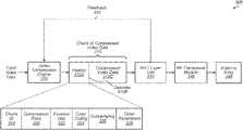
- transmitter 300includes video compression engine 310 , media access control (MAC) layer unit 330 , RF transceiver module 340 , and antenna array 345 .
- Video compression engine 310can also be referred to as a codec or encoder.
- Video compression engine 310 and MAC layer unit 330can be implemented with any suitable combination of hardware and/or software.
- Transmitter 300can also include other logic that is not shown in FIG. 3 to avoid obscuring the figure.
- Video compression engine 310is configured to receive input video data and to generate a chunk of compressed video data 315 for each given portion of the input video data.
- each chunk of compressed video data 315corresponds to a single frame of the input video data.
- each chunk of compressed video data 315corresponds to a portion of a single frame of the input video data.
- Each chunk of compressed video data 315includes a header 315 A, delimiter 315 B, and compressed video data 315 C. Header 315 A is expanded to show the components that are located in chunk 315 prior to delimiter 315 B.
- Header 315 Aincludes chunk (or block) identifier (ID) 318 , compression ratio 320 , fovation map 322 , color coding settings 324 , subsampling settings 326 , and other parameters 328 .
- header 315 Acan include other parameters and/or header 315 A can be formatted differently.
- the compression ratiois defined as the ratio between the uncompressed size of a video frame and the compressed size of the video frame. For example, if video compression engine 310 compresses a video frame from a size of 10 megabytes (MB) to 2 MB, the compression ratio for this given video frame is 5.
- a compression ratio of 5can also be expressed as 5:1 or 5/1.
- MAC layer unit 330is configured to extract the header 315 A from each received chunk of compressed video data 315 .
- MAC layer unit 330is configured to utilize the compression ratio 320 when determining how to modulate the chunk of compressed video data 315 . Then, MAC layer unit 330 provides the modulated data to RF transceiver module 340 and antenna array 345 to be sent wirelessly to the receiver (e.g., HMD 220 of FIG. 2 ).
- MAC layer unit 330can select a first MCS level for modulating the compressed video data. Otherwise, if the compression ratio is above the given threshold, then MAC layer unit 330 can utilize a second MCS level for modulating the chunk of compressed video data 315 , wherein the second MCS level less than the first MCS level. MAC layer unit 330 can compare the compression ratio to any number of thresholds and choose a MCS level for modulating the compressed video data 315 C based on which two thresholds the compression ratio falls between.
- MAC layer unit 330is configured to provide feedback 335 to video compression engine 310 .
- MAC layer unit 330sends a request to video compression engine 310 to change the compression ratio of the compressed video data 315 B.
- MAC layer unit 330requests for video compression engine 310 to adjust the compression ratio based on detecting a change in the link condition. For example, if the link condition deteriorates, MAC layer unit 330 can request that video compression engine 310 increase the compression ratio so that there is less data to send on the link.
- video compression engine 310can continue to compress several chunks of data before the change is actually implemented.
- MAC layer unit 330extracts the header 315 A and retrieves compression ratio 320 to determine the actual compression ratio 320 that was achieved for the compressed video data 315 C. MAC layer unit 330 can then determine how to modulate the compressed video data 315 B based on the actual compression ratio 320 .
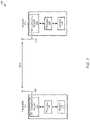
- FIG. 4a block diagram of one embodiment of a MAC layer unit 400 is shown.
- the logic of MAC layer unit 400is included within MAC layer unit 330 (of FIG. 3 ).
- MAC layer unit 400includes control unit 410 , MCS selection unit 440 , and modulation unit 450 .
- MAC layer unit 400is configured to extract compression ratio 405 from a header (e.g., header 315 A of FIG. 3 ) which is included within a given chunk of compressed video data.
- MCS level selection unit 440is configured to utilize the compression ratio 405 to determine which MCS level to utilize when modulating the compressed video data 420 which is sent over a wireless link to the receiver (not shown).
- An indication of the selected MCS levelis provided to modulation unit 450 for modulating the compressed video data 420 which will be sent over the wireless link.
- MCS level selection unit 440includes or is coupled to table 445 .
- Table 445includes entries that map a given compression ratio to a corresponding MCS level. For example, if the compression ratio is low (i.e., less than a first threshold), then a MCS level of 7 is utilized when modulating the compressed video data 420 . Alternatively, if the compression ratio is medium (i.e., greater than the first threshold but less than a second threshold), then a MCS level of 4 is utilized. Still further, if the compression ratio is high (i.e., greater than the second threshold), then a MCS level of 1 is utilized. It should be understood that the mappings of compression ratio to MCS level shown in table 445 are merely indicative of one particular embodiment.
- mappingscan be utilized.
- table 445can have other numbers of entries to map compression ratios to different MCS levels.
- MCS level selection unit 440can utilize other techniques for mapping compression ratios to MCS levels.
- control unit 410is configured to receive link quality parameters 415 which are generated by beamforming training module 430 .
- beamforming training module 430is configured to monitor the quality of the wireless link during beamforming training and generate link quality parameters 415 based on the quality of the link.
- the link quality parameters 415give control unit 410 a measure of the current link quality of the link.
- control unit 410is configured to provide feedback to the codec (e.g., video compression engine 310 ) to request that the codec adjust the compression ratio of the compressed video data. For example, if the current link quality is poor (i.e., less than a threshold), then control unit 410 can request that the codec increase the compression ratio.
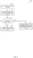
- FIG. 5one embodiment of a method 500 for selecting a MCS level for modulating video data is shown.
- the steps in this embodiment and those of FIG. 6-7are shown in sequential order.
- one or more of the elements describedare performed concurrently, in a different order than shown, or are omitted entirely.
- Other additional elementsare also performed as desired. Any of the various systems or apparatuses described herein are configured to implement method 500 .
- a MAC layerreceives a chunk of compressed video data from a codec (block 505 ). Next, the MAC layer retrieves the compression ratio from a header of the chunk of compressed video data (block 510 ). Then, the MAC layer selects a MCS level for modulating the compressed video data based on the compression ratio (block 515 ). If another chunk of compressed video data has been received (conditional block 520 , “yes” leg), then method 500 returns to block 510 . If the MAC layer has not received another chunk of compressed video data (conditional block 520 , “no” leg), then the MAC layer monitors the condition of the wireless link (block 525 ).
- condition block 530If the wireless link condition has changed (conditional block 530 , “yes” leg), then the MAC layer sends feedback to the codec to change the compression settings used for compressing the raw video frame data (block 535 ). After block 535 , method 500 returns to conditional block 520 . If the wireless link condition has not changed (conditional block 530 , “no” leg), then method 500 returns to conditional block 520 .
- a codecreceives a given video frame to be compressed (block 605 ).
- the codeccompresses the given video frame using a given set of video compression settings (block 610 ).
- the codeccalculates the compression ratio that was achieved for the given video frame (block 615 ).
- the codecstores an indication of the compression ratio in a header of a chunk of compressed video data (block 620 ).
- the codecsends the chunk of compressed video data with the header to the MAC layer unit (block 625 ).
- condition block 630If the codec receives a request from the MAC layer unit to change the video compression settings (conditional block 630 , “yes” leg), then the codec adjusts the compression settings based on the request from the MAC layer unit (block 635 ). Otherwise, if the codec does not receive a request from the MAC layer unit to change the video compression settings (conditional block 630 , “no” leg), then the codec maintains the existing compression settings (block 640 ). After blocks 635 and 640 , method 600 returns to block 605 .
- a MAC layer unitreceives a chunk of compressed video data from a codec (e.g., video compression engine 310 of FIG. 3 ) (block 705 ).
- the MAC layer unitretrieves an indication of the compression ratio from a header of the chunk of compressed video data (block 710 ). If the compression ratio is greater than a threshold (conditional block 715 , “yes” leg), then the MAC layer unit utilizes a first MCS level for modulating the compressed video data (block 720 ).
- the MAC layer unitutilizes a second MCS level for modulating the compressed video data, wherein the second MCS level is higher than the first MCS level (block 725 ).
- method 700ends. It is noted that in other embodiments, method 700 can be modified so that the MAC layer unit compares the compression ratio to any number of other thresholds and selects from more than two different MCS levels based on the comparisons.
- program instructions of a software applicationare used to implement the methods and/or mechanisms described herein.
- program instructions executable by a general or special purpose processorare contemplated.
- such program instructionscan be represented by, a high level programming language.
- the program instructionscan be compiled from a high level programming language to a binary, intermediate, or other form.
- program instructionscan be written that describe the behavior or design of hardware.
- Such program instructionscan be represented by a high-level programming language, such as C.
- a hardware design language (HDL)such as Verilog can be used.
- the program instructionsare stored on any of a variety of non-transitory computer readable storage mediums. The storage medium is accessible by a computing system during use to provide the program instructions to the computing system for program execution.
- a computing systemincludes at least one or more memories and one or more processors configured to execute program instructions.
Landscapes
- Engineering & Computer Science (AREA)
- Signal Processing (AREA)
- Computer Networks & Wireless Communication (AREA)
- Multimedia (AREA)
- Quality & Reliability (AREA)
- Computer Security & Cryptography (AREA)
- Mobile Radio Communication Systems (AREA)
Abstract
Description
Claims (20)
Priority Applications (1)
| Application Number | Priority Date | Filing Date | Title |
|---|---|---|---|
| US15/834,400US11290515B2 (en) | 2017-12-07 | 2017-12-07 | Real-time and low latency packetization protocol for live compressed video data |
Applications Claiming Priority (1)
| Application Number | Priority Date | Filing Date | Title |
|---|---|---|---|
| US15/834,400US11290515B2 (en) | 2017-12-07 | 2017-12-07 | Real-time and low latency packetization protocol for live compressed video data |
Publications (2)
| Publication Number | Publication Date |
|---|---|
| US20190182308A1 US20190182308A1 (en) | 2019-06-13 |
| US11290515B2true US11290515B2 (en) | 2022-03-29 |
Family
ID=66696553
Family Applications (1)
| Application Number | Title | Priority Date | Filing Date |
|---|---|---|---|
| US15/834,400Active2039-02-09US11290515B2 (en) | 2017-12-07 | 2017-12-07 | Real-time and low latency packetization protocol for live compressed video data |
Country Status (1)
| Country | Link |
|---|---|
| US (1) | US11290515B2 (en) |
Families Citing this family (6)
| Publication number | Priority date | Publication date | Assignee | Title |
|---|---|---|---|---|
| US10523947B2 (en) | 2017-09-29 | 2019-12-31 | Ati Technologies Ulc | Server-based encoding of adjustable frame rate content |
| US10594901B2 (en) | 2017-11-17 | 2020-03-17 | Ati Technologies Ulc | Game engine application direct to video encoder rendering |
| US11100604B2 (en) | 2019-01-31 | 2021-08-24 | Advanced Micro Devices, Inc. | Multiple application cooperative frame-based GPU scheduling |
| US11418797B2 (en) | 2019-03-28 | 2022-08-16 | Advanced Micro Devices, Inc. | Multi-plane transmission |
| US11488328B2 (en) | 2020-09-25 | 2022-11-01 | Advanced Micro Devices, Inc. | Automatic data format detection |
| US20240340695A1 (en)* | 2023-04-07 | 2024-10-10 | Qualcomm Incorporated | Semi-persistent scheduling and compression adaptation |
Citations (53)
| Publication number | Priority date | Publication date | Assignee | Title |
|---|---|---|---|---|
| US5930390A (en) | 1996-03-28 | 1999-07-27 | Intel Corporation | Encoding/decoding signals using a remap table |
| US20010033286A1 (en) | 2000-02-25 | 2001-10-25 | Stokes Michael D. | Method and data arrangement for encapsulating signed over-ranged color image data to accommodate in-range file formats |
| US6524198B2 (en) | 2000-07-07 | 2003-02-25 | K.K. Endo Seisakusho | Golf club and method of manufacturing the same |
| US6618397B1 (en)* | 2000-10-05 | 2003-09-09 | Provisionpoint Communications, Llc. | Group packet encapsulation and compression system and method |
| US6680976B1 (en) | 1997-07-28 | 2004-01-20 | The Board Of Trustees Of The University Of Illinois | Robust, reliable compression and packetization scheme for transmitting video |
| US6683988B1 (en) | 1998-10-08 | 2004-01-27 | Oki Electric Industry Co., Ltd. | Picture transmission system using minimal reference-frame modification to recover from transmission errors |
| US6754234B1 (en) | 1999-05-21 | 2004-06-22 | Ati International Srl | Method and apparatus for asynchronous frame synchronization |
| US20050223165A1 (en) | 2004-03-31 | 2005-10-06 | Microsoft Corporation | Strategies for reading information from a mass storage medium using a cache memory |
| US20060171596A1 (en) | 2005-01-28 | 2006-08-03 | Sung Chih-Ta S | Method and apparatus for displaying images with compression mechanism |
| US20080049651A1 (en) | 2001-01-19 | 2008-02-28 | Chang William H | Output controller systems, method, software, and device for wireless data output |
| US7471823B2 (en) | 2001-12-03 | 2008-12-30 | Apple Inc. | Color correction control graphical user interface |
| US20090052537A1 (en) | 2004-11-04 | 2009-02-26 | Koninklijke Philips Electronics, N.V. | Method and device for processing coded video data |
| US20090148058A1 (en) | 2007-12-10 | 2009-06-11 | Qualcomm Incorporated | Reference selection for video interpolation or extrapolation |
| US20090213940A1 (en) | 2008-02-26 | 2009-08-27 | Richwave Technology Corp. | Error Resilient Video Transmission Using Instantaneous Receiver Feedback and Channel Quality Adaptive Packet Retransmission |
| US20100050225A1 (en) | 2008-08-25 | 2010-02-25 | Broadcom Corporation | Source frame adaptation and matching optimally to suit a recipient video device |
| US20100157154A1 (en) | 2007-08-02 | 2010-06-24 | Sony Corporation | Image processing apparatus |
| US20100177776A1 (en) | 2009-01-09 | 2010-07-15 | Microsoft Corporation | Recovering from dropped frames in real-time transmission of video over ip networks |
| US7813000B2 (en) | 2003-12-30 | 2010-10-12 | Microsoft Corporation | Device color characterization profile format |
| US20110050695A1 (en) | 2009-09-01 | 2011-03-03 | Entertainment Experience Llc | Method for producing a color image and imaging device employing same |
| US20110066262A1 (en) | 2008-01-22 | 2011-03-17 | Carnegie Mellon University | Apparatuses, Systems, and Methods for Apparatus Operation and Remote Sensing |
| US20110157196A1 (en) | 2005-08-16 | 2011-06-30 | Exent Technologies, Ltd. | Remote gaming features |
| US20110263332A1 (en) | 2006-04-13 | 2011-10-27 | Yosef Mizrachi | Method and apparatus for providing gaming services and for handling video content |
| US20110299606A1 (en) | 2010-06-04 | 2011-12-08 | Xuemin Chen | Method and system for providing selected layered video service via a broadband gateway |
| US20120008679A1 (en) | 2010-07-07 | 2012-01-12 | Steve Bakke | 4:4:4 color space video with 4:2:0 color space video encoders and decoders systems and methods |
| US20120079329A1 (en) | 2008-02-26 | 2012-03-29 | RichWave Technology Corporation | Adaptive wireless video transmission systems and methods |
| US8175181B1 (en)* | 2007-05-31 | 2012-05-08 | Marvell International Ltd. | Method and apparatus for selecting a modulation coding scheme |
| US20120236934A1 (en) | 2011-03-18 | 2012-09-20 | Qualcomm Incorporated | Signaling of multiview video plus depth content with a block-level 4-component structure |
| US20120243009A1 (en) | 2011-03-23 | 2012-09-27 | Xerox Corporation | Uv and ir specialty imaging methods and systems |
| US20130039594A1 (en) | 2010-04-20 | 2013-02-14 | Quqing Chen | Method and device for encoding data for rendering at least one image using computer graphics and corresponding method and device for decoding |
| US20130053141A1 (en) | 2011-08-22 | 2013-02-28 | Xerox Corporation | Photograph-based game |
| US20130058394A1 (en) | 2011-09-02 | 2013-03-07 | Mattias Nilsson | Video Coding |
| US20130076771A1 (en) | 2011-09-23 | 2013-03-28 | Apple Inc. | Generating a visual depiction of a cover for a digital item |
| US20130083161A1 (en) | 2011-09-30 | 2013-04-04 | University Of Illinois | Real-time video coding using graphics rendering contexts |
| US20130335432A1 (en) | 2011-11-07 | 2013-12-19 | Square Enix Holdings Co., Ltd. | Rendering server, central server, encoding apparatus, control method, encoding method, and recording medium |
| US20140028876A1 (en) | 2012-07-24 | 2014-01-30 | Christopher L. Mills | Image stabilization using striped output transformation unit |
| WO2014078452A1 (en) | 2012-11-16 | 2014-05-22 | Sony Computer Entertainment America Llc | Systems and methods for cloud processing and overlaying of content on streaming video frames of remotely processed applications |
| US20140194196A1 (en) | 2013-01-04 | 2014-07-10 | International Business Machines Corporation | Access control of user based photograph bundles |
| US20140211860A1 (en) | 2013-01-28 | 2014-07-31 | Microsoft Corporation | Conditional concealment of lost video data |
| US20140267780A1 (en) | 2013-03-14 | 2014-09-18 | Microsoft Corporation | Hdmi image quality analysis |
| US20140317068A1 (en)* | 2007-06-01 | 2014-10-23 | Blackberry Limited | Determination of compression state information for use in interactive compression |
| US20140372918A1 (en) | 2013-06-17 | 2014-12-18 | Hon Hai Precision Industry Co., Ltd. | System and method for adjusting position of user interface of application |
| US20140376612A1 (en) | 2012-01-04 | 2014-12-25 | Dolby Laboratories Licensing Corporation | Dual-Layer Backwards-Compatible Progressive Video Delivery |
| US20150296215A1 (en) | 2014-04-11 | 2015-10-15 | Microsoft Corporation | Frame encoding using hints |
| US9270969B2 (en) | 2009-03-04 | 2016-02-23 | Ati Technologies Ulc | 3D video processing |
| US9407923B2 (en) | 2013-05-20 | 2016-08-02 | Gamefly Israel Ltd. | Overconing lost IP packets in streaming video in IP networks |
| US20160358305A1 (en) | 2015-06-07 | 2016-12-08 | Apple Inc. | Starvation free scheduling of prioritized workloads on the gpu |
| US20160381392A1 (en) | 2010-07-15 | 2016-12-29 | Ge Video Compression, Llc | Hybrid video coding supporting intermediate view synthesis |
| US20170142447A1 (en) | 2015-06-12 | 2017-05-18 | Intel Corporation | Facilitating environment-based lossy compression of data for efficient rendering of contents at computing devices |
| US9924134B2 (en) | 2006-08-31 | 2018-03-20 | Ati Technologies Ulc | Dynamic frame rate adjustment |
| US20180091819A1 (en)* | 2016-09-26 | 2018-03-29 | Samsung Display Co., Ltd. | System and method for electronic data communication |
| US20190068983A1 (en) | 2017-08-25 | 2019-02-28 | Advanced Micro Devices, Inc. | Sending a Frame Difference or Raw Chunk Based on a Known Acknowledgement |
| US20190104311A1 (en) | 2017-09-29 | 2019-04-04 | Ati Technologies Ulc | Server-based encoding of adjustable frame rate content |
| US20190158704A1 (en) | 2017-11-17 | 2019-05-23 | Ati Technologies Ulc | Game engine application direct to video encoder rendering |
- 2017
- 2017-12-07USUS15/834,400patent/US11290515B2/enactiveActive
Patent Citations (55)
| Publication number | Priority date | Publication date | Assignee | Title |
|---|---|---|---|---|
| US5930390A (en) | 1996-03-28 | 1999-07-27 | Intel Corporation | Encoding/decoding signals using a remap table |
| US6680976B1 (en) | 1997-07-28 | 2004-01-20 | The Board Of Trustees Of The University Of Illinois | Robust, reliable compression and packetization scheme for transmitting video |
| US6683988B1 (en) | 1998-10-08 | 2004-01-27 | Oki Electric Industry Co., Ltd. | Picture transmission system using minimal reference-frame modification to recover from transmission errors |
| US6754234B1 (en) | 1999-05-21 | 2004-06-22 | Ati International Srl | Method and apparatus for asynchronous frame synchronization |
| US20010033286A1 (en) | 2000-02-25 | 2001-10-25 | Stokes Michael D. | Method and data arrangement for encapsulating signed over-ranged color image data to accommodate in-range file formats |
| US6524198B2 (en) | 2000-07-07 | 2003-02-25 | K.K. Endo Seisakusho | Golf club and method of manufacturing the same |
| US6618397B1 (en)* | 2000-10-05 | 2003-09-09 | Provisionpoint Communications, Llc. | Group packet encapsulation and compression system and method |
| US20080049651A1 (en) | 2001-01-19 | 2008-02-28 | Chang William H | Output controller systems, method, software, and device for wireless data output |
| US7471823B2 (en) | 2001-12-03 | 2008-12-30 | Apple Inc. | Color correction control graphical user interface |
| US7813000B2 (en) | 2003-12-30 | 2010-10-12 | Microsoft Corporation | Device color characterization profile format |
| US20050223165A1 (en) | 2004-03-31 | 2005-10-06 | Microsoft Corporation | Strategies for reading information from a mass storage medium using a cache memory |
| US20090052537A1 (en) | 2004-11-04 | 2009-02-26 | Koninklijke Philips Electronics, N.V. | Method and device for processing coded video data |
| US20060171596A1 (en) | 2005-01-28 | 2006-08-03 | Sung Chih-Ta S | Method and apparatus for displaying images with compression mechanism |
| US20110157196A1 (en) | 2005-08-16 | 2011-06-30 | Exent Technologies, Ltd. | Remote gaming features |
| US20110263332A1 (en) | 2006-04-13 | 2011-10-27 | Yosef Mizrachi | Method and apparatus for providing gaming services and for handling video content |
| US9924134B2 (en) | 2006-08-31 | 2018-03-20 | Ati Technologies Ulc | Dynamic frame rate adjustment |
| US8175181B1 (en)* | 2007-05-31 | 2012-05-08 | Marvell International Ltd. | Method and apparatus for selecting a modulation coding scheme |
| US20140317068A1 (en)* | 2007-06-01 | 2014-10-23 | Blackberry Limited | Determination of compression state information for use in interactive compression |
| US20100157154A1 (en) | 2007-08-02 | 2010-06-24 | Sony Corporation | Image processing apparatus |
| US20090148058A1 (en) | 2007-12-10 | 2009-06-11 | Qualcomm Incorporated | Reference selection for video interpolation or extrapolation |
| US20110066262A1 (en) | 2008-01-22 | 2011-03-17 | Carnegie Mellon University | Apparatuses, Systems, and Methods for Apparatus Operation and Remote Sensing |
| US20090213940A1 (en) | 2008-02-26 | 2009-08-27 | Richwave Technology Corp. | Error Resilient Video Transmission Using Instantaneous Receiver Feedback and Channel Quality Adaptive Packet Retransmission |
| US20120079329A1 (en) | 2008-02-26 | 2012-03-29 | RichWave Technology Corporation | Adaptive wireless video transmission systems and methods |
| US20100050225A1 (en) | 2008-08-25 | 2010-02-25 | Broadcom Corporation | Source frame adaptation and matching optimally to suit a recipient video device |
| US20100177776A1 (en) | 2009-01-09 | 2010-07-15 | Microsoft Corporation | Recovering from dropped frames in real-time transmission of video over ip networks |
| US9270969B2 (en) | 2009-03-04 | 2016-02-23 | Ati Technologies Ulc | 3D video processing |
| US20110050695A1 (en) | 2009-09-01 | 2011-03-03 | Entertainment Experience Llc | Method for producing a color image and imaging device employing same |
| US20130039594A1 (en) | 2010-04-20 | 2013-02-14 | Quqing Chen | Method and device for encoding data for rendering at least one image using computer graphics and corresponding method and device for decoding |
| US20110299606A1 (en) | 2010-06-04 | 2011-12-08 | Xuemin Chen | Method and system for providing selected layered video service via a broadband gateway |
| US20120008679A1 (en) | 2010-07-07 | 2012-01-12 | Steve Bakke | 4:4:4 color space video with 4:2:0 color space video encoders and decoders systems and methods |
| US20160381392A1 (en) | 2010-07-15 | 2016-12-29 | Ge Video Compression, Llc | Hybrid video coding supporting intermediate view synthesis |
| US20120236934A1 (en) | 2011-03-18 | 2012-09-20 | Qualcomm Incorporated | Signaling of multiview video plus depth content with a block-level 4-component structure |
| US20120243009A1 (en) | 2011-03-23 | 2012-09-27 | Xerox Corporation | Uv and ir specialty imaging methods and systems |
| US20130053141A1 (en) | 2011-08-22 | 2013-02-28 | Xerox Corporation | Photograph-based game |
| US20130058394A1 (en) | 2011-09-02 | 2013-03-07 | Mattias Nilsson | Video Coding |
| US20130076771A1 (en) | 2011-09-23 | 2013-03-28 | Apple Inc. | Generating a visual depiction of a cover for a digital item |
| US20130083161A1 (en) | 2011-09-30 | 2013-04-04 | University Of Illinois | Real-time video coding using graphics rendering contexts |
| US20130335432A1 (en) | 2011-11-07 | 2013-12-19 | Square Enix Holdings Co., Ltd. | Rendering server, central server, encoding apparatus, control method, encoding method, and recording medium |
| US20140376612A1 (en) | 2012-01-04 | 2014-12-25 | Dolby Laboratories Licensing Corporation | Dual-Layer Backwards-Compatible Progressive Video Delivery |
| US20140028876A1 (en) | 2012-07-24 | 2014-01-30 | Christopher L. Mills | Image stabilization using striped output transformation unit |
| WO2014078452A1 (en) | 2012-11-16 | 2014-05-22 | Sony Computer Entertainment America Llc | Systems and methods for cloud processing and overlaying of content on streaming video frames of remotely processed applications |
| JP2016505291A (en) | 2012-11-16 | 2016-02-25 | ソニー コンピュータ エンタテインメント アメリカ リミテッド ライアビリテイ カンパニー | System and method for cloud processing and overlaying of content on streaming video frames of remotely processed applications |
| US20140194196A1 (en) | 2013-01-04 | 2014-07-10 | International Business Machines Corporation | Access control of user based photograph bundles |
| US20140211860A1 (en) | 2013-01-28 | 2014-07-31 | Microsoft Corporation | Conditional concealment of lost video data |
| US20140267780A1 (en) | 2013-03-14 | 2014-09-18 | Microsoft Corporation | Hdmi image quality analysis |
| US9407923B2 (en) | 2013-05-20 | 2016-08-02 | Gamefly Israel Ltd. | Overconing lost IP packets in streaming video in IP networks |
| US20140372918A1 (en) | 2013-06-17 | 2014-12-18 | Hon Hai Precision Industry Co., Ltd. | System and method for adjusting position of user interface of application |
| US20150296215A1 (en) | 2014-04-11 | 2015-10-15 | Microsoft Corporation | Frame encoding using hints |
| JP2017517921A (en) | 2014-04-11 | 2017-06-29 | マイクロソフト テクノロジー ライセンシング,エルエルシー | Frame encoding with hints |
| US20160358305A1 (en) | 2015-06-07 | 2016-12-08 | Apple Inc. | Starvation free scheduling of prioritized workloads on the gpu |
| US20170142447A1 (en) | 2015-06-12 | 2017-05-18 | Intel Corporation | Facilitating environment-based lossy compression of data for efficient rendering of contents at computing devices |
| US20180091819A1 (en)* | 2016-09-26 | 2018-03-29 | Samsung Display Co., Ltd. | System and method for electronic data communication |
| US20190068983A1 (en) | 2017-08-25 | 2019-02-28 | Advanced Micro Devices, Inc. | Sending a Frame Difference or Raw Chunk Based on a Known Acknowledgement |
| US20190104311A1 (en) | 2017-09-29 | 2019-04-04 | Ati Technologies Ulc | Server-based encoding of adjustable frame rate content |
| US20190158704A1 (en) | 2017-11-17 | 2019-05-23 | Ati Technologies Ulc | Game engine application direct to video encoder rendering |
Non-Patent Citations (7)
| Title |
|---|
| Cheng et al., U.S. Appl. No. 16/263,709, entitled "Multiple Application Cooperative Frame-Based GPU Scheduling", filed Jan. 31, 2019, 33 pages. |
| International Search Report and Written Opinion in International Application No. PCT/IB2018/057511, dated Jan. 22, 2019, 8 pages. |
| Non-Final Office Action in Japanese Patent Application No. 2020-526583, dated Jan. 25, 2022, 11 pages. |
| Non-Final Office Action in U.S. Appl. No. 15/686,892, dated Jun. 1, 2020, 14 pages. |
| Non-Final Office Action in U.S. Appl. No. 15/816,765, dated Jun. 26, 2019, 11 pages. |
| Non-Final Office Action in U.S. Appl. No. 16/263,709, dated Mar. 18, 2020, 9 pages. |
| Office Action in Korean Patent Application No. 10-2020-7016094, dated Nov. 3, 2021, 10 pages. |
Also Published As
| Publication number | Publication date |
|---|---|
| US20190182308A1 (en) | 2019-06-13 |
Similar Documents
| Publication | Publication Date | Title |
|---|---|---|
| US11290515B2 (en) | Real-time and low latency packetization protocol for live compressed video data | |
| KR102706269B1 (en) | Adjustable modulation coding scheme to increase video stream robustness | |
| EP3729809B1 (en) | Video codec data recovery techniques for lossy wireless links | |
| US10680927B2 (en) | Adaptive beam assessment to predict available link bandwidth | |
| JP2020535755A6 (en) | Tunable modulation and coding scheme to increase the robustness of video streams | |
| KR102773525B1 (en) | Controlling the slice size map of foveated coding | |
| EP1993237B1 (en) | Multimedia client/server system with adjustable packet size and methods for use therewith | |
| CN103096084B (en) | Method, the Apparatus and system of code check Automatic adjusument in a kind of wireless transmission | |
| CN105493508B (en) | Information processing apparatus, information processing method, and computer program | |
| US20190173544A1 (en) | Beamforming techniques to choose transceivers in a wireless mesh network | |
| CN102118357A (en) | Method, device and system for processing streaming media | |
| CN103828384A (en) | Software based wireless channel-aware adaptive video bit rate encoding | |
| WO2019029624A1 (en) | Method and device for communication | |
| US20240305841A1 (en) | Dynamic resolution switching for camera | |
| US10972752B2 (en) | Stereoscopic interleaved compression | |
| US20230388862A1 (en) | Transmission parameter adjustment method and communication apparatus | |
| KR101196452B1 (en) | Apparatus and method for transfering bitstream | |
| HK40002996A (en) | Coding and decoding method and device |
Legal Events
| Date | Code | Title | Description |
|---|---|---|---|
| AS | Assignment | Owner name:ADVANCED MICRO DEVICES, INC., CALIFORNIA Free format text:ASSIGNMENT OF ASSIGNORS INTEREST;ASSIGNORS:VU, NGOC VINH;DI CERA, DARREN RAE;LYNCH, ADAM WILLIAM;AND OTHERS;SIGNING DATES FROM 20171201 TO 20171207;REEL/FRAME:044328/0240 | |
| FEPP | Fee payment procedure | Free format text:ENTITY STATUS SET TO UNDISCOUNTED (ORIGINAL EVENT CODE: BIG.); ENTITY STATUS OF PATENT OWNER: LARGE ENTITY | |
| STPP | Information on status: patent application and granting procedure in general | Free format text:RESPONSE TO NON-FINAL OFFICE ACTION ENTERED AND FORWARDED TO EXAMINER | |
| STPP | Information on status: patent application and granting procedure in general | Free format text:FINAL REJECTION MAILED | |
| STPP | Information on status: patent application and granting procedure in general | Free format text:RESPONSE AFTER FINAL ACTION FORWARDED TO EXAMINER | |
| STCV | Information on status: appeal procedure | Free format text:NOTICE OF APPEAL FILED | |
| STCV | Information on status: appeal procedure | Free format text:APPEAL BRIEF (OR SUPPLEMENTAL BRIEF) ENTERED AND FORWARDED TO EXAMINER | |
| STCV | Information on status: appeal procedure | Free format text:ON APPEAL -- AWAITING DECISION BY THE BOARD OF APPEALS | |
| STCV | Information on status: appeal procedure | Free format text:BOARD OF APPEALS DECISION RENDERED | |
| STPP | Information on status: patent application and granting procedure in general | Free format text:NOTICE OF ALLOWANCE MAILED -- APPLICATION RECEIVED IN OFFICE OF PUBLICATIONS | |
| STPP | Information on status: patent application and granting procedure in general | Free format text:AWAITING TC RESP., ISSUE FEE NOT PAID | |
| STPP | Information on status: patent application and granting procedure in general | Free format text:NOTICE OF ALLOWANCE MAILED -- APPLICATION RECEIVED IN OFFICE OF PUBLICATIONS | |
| STPP | Information on status: patent application and granting procedure in general | Free format text:PUBLICATIONS -- ISSUE FEE PAYMENT VERIFIED | |
| STCF | Information on status: patent grant | Free format text:PATENTED CASE | |
| MAFP | Maintenance fee payment | Free format text:PAYMENT OF MAINTENANCE FEE, 4TH YEAR, LARGE ENTITY (ORIGINAL EVENT CODE: M1551); ENTITY STATUS OF PATENT OWNER: LARGE ENTITY Year of fee payment:4 |